Donald E. Wilcox et al- Location of Mach Discs and Diamonds in Supersonic Air Jets
NASA Technical Memorandum 106364
AIAA-93--4322 i .P
Mixing Noise Reduction for RectangularSupersonic Jets by Nozzle Shapingand Induced Screech Mixing
Edward J. Rice
National Aeronautics and Space AdministrationLewis Research Center
Cleveland, Ohio
and
Ganesh Raman
Sverdrup Technology, Inc.Lewis Research Center Group
Brook Park, Ohio
Prepared for the15th AIAAAeroacoustics Conference
sponsored by the American Institute of Aeronautics and Astronautics
Long Beach, California, October 25-27, 1993
I IASA
(NASA-TM-106364) MIXING NOISE
REDUCTION FOR RECTANGULAR
SUPERSONIC JETS BY NOZZLE SHAPING
AND INOUCEO SCREECH MIXING (NASA)
12 D
N94-14208
Unclas
G3/02 0189380
https://ntrs.nasa.gov/search.jsp?R=19940009735 2020-04-02T09:26:37+00:00Z


MIXINGNOISEREDUCTIONFOR RECTANGULAR SUPERSONIC JETS
BY NOZZLE SHAPING AND INDUCED SCREECH MIXING
by
Edward J. Rice*
National Aeronautics and Space AdministrationLewis Research Center
Cleveland, Ohio 44135
and
Ganesh Raman**
Sverdrup Technology Inc.
NASA Lewis Research Center GroupCleveland, Ohio 44135
Abstract
Two methods of mixing noise modification were
studied for supersonic jets flowing from rectangular
nozzles with an aspect ratio of about five and a smalldimension of about 1.4 cm. The fn'st involves nozzle
geometry variation using either single (unsymmetrical) ordouble bevelled (symmetrical) thirty degree cutbacks of
the nozzle exit. Both converging (C) and converging-
diverging (C-D) versions were tested. The doublebevelled C-D nozzle produced a jet mixing noise
reduction of about 4 dB compared to a standard
rectangular C-D nozzle. In addition all bevelled nozzles
produced an upstream shift in peak mixing noise which is
conducive to improved attenuation when the nozzle is
used in an acoustically treated duct. A large increase in
high frequency noise also occurred near the plane of thenozzle exit. Because of near normal incidence, this noise
can be easily attenuated with wall treatment. The second
approach uses paddles inserted on the edge of the twosides of the jet to induce screech and greatly enhance the
jet mixing. Although screech and mixing noise levels areincreased, the enhanced mixing moves the source
locations upstream and may make an enclosed system
more amenable to noise reduction using wall acoustic
treatment.
Introduction
The objective of this research is to study ways in
which the noise of a supersonic rectangular jet can be
significantly reduced using excitation or other shear flowcontrol means which could find practical application in a
*Lewis Distinguished Research Associate, retired,Member AIAA
**Research Engineer
Copyright © 1993 by the American Institute of Aeronauticsand Astronautics, Inc. No copyright is asserted in the
United States under Title 17, U.S. Code. The U.S. Govern-ment has a royalty-free license to exercise all rights underthe copyright claimed herein for Governmental purposes.
All other rights are reserved by the copyright owner.
single or multiple jet mixer or ejector device. It isintended that this excitation device be a natural source
which feeds upon the steady flow for its energy rather
than requiring an external power source of any kind. The
emphasis of this work was to investigate geometries whichwould be used internal to a shroud and this has led to the
concentration on near-field hydrodynamic and acoustic
fields. Two approaches to improving the performance ofsuch devices seem obvious. The first is to cause the
direetivity of the internally generated mixing noise to bemore normal to the acoustic treatment surface which
would make the suppressor much more effective. An
attempt to accomplish this first objective led to thedouble-beveled nozzle tests which are reported here. In
some, but not all cases, the directivity was significantly
changed for the mixing noise frequencies of interest, and
the jet noise was reduced significantly. Thus the bevelled
nozzle may be a candidate for the internal mixer-ejectorswhere properly designed acoustic treatment might be used
to further exploit the directivity changes. The second
approach is to increase the mixing rate of the jets to move
the jet noise source back toward the nozzle lip and thus
provide a longer propagation length for an acoustic lining
to reduce the internal mixing noise. Mixing enhancement
of the supersonic jet flow from a converging-diverging
rectangular nozzle operated at design pressure was
obtained using paddles to induce screech and cause jet
flapping.
Seiner and Krejsa I have discussed the status of
supersonic jet noise reduction relative to the supersonic
transport. A large reduction in jet noise will be necessaryfor such an aircraft to meet anticipated noise goals. The
work reported in this paper is intended to explore the two
approaches mentioned above to help provide an efficient
method to achieve some of this required noise reduction.
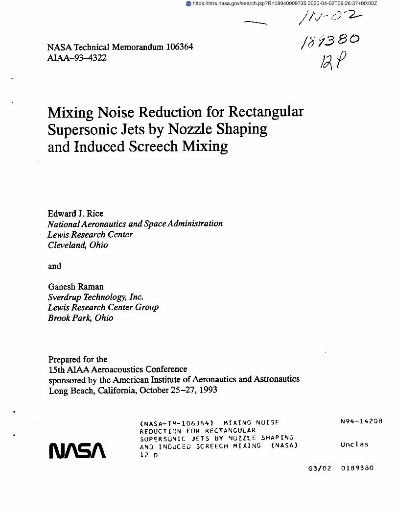
A . . Flow quality control--., _.....I--, ,.nnular nngs _ _ _
r Air supply ', ,__ (_1"kf-_ _ I..-_
i
n,me
X_.lnflow conditioning
Figure 1. Schematic of supersonic jet flow rig
Tam 2 and Lilley 3 have provided excellent recent reviews
of the fundamentals of jet noise production. The idea that
the jet noise is intimately involved with the large coherent
structures produced in the jet mixing process is
particularly relevant here. This paper reports research
based upon the manipulation of these structures to try to
effect a jet noise reduction.Seiner _ et al. and Ponton 5 et al. have extensively
measured the noise produced by supersonic rectangular
jets. Wlezien and Kibens 6 have conducted experiments on
the noise generated by supersonic jets formed by roundnozzles with unsymmetrical exits. One additional element
found in the research reported here is that some of the
nozzles are converging-diverging nozzles running nearly
shock free at the design pressure differing from the
previously reported converging nozzles with the resulting
strong shock structures. A second additional element is
that the jet instability and thus the large coherent
structures are manipulated to alter the jet noise. Also the
double bevelled converging-diverging nozzle discussed
here has the flow emerging almost axially rather than
being diverted to the side as in the converging nozzles ofreference 6.
This paper represents an extension of the work
reported by Rice and Raman 7,s. In reference 7 the use of
paddles was first introduced to induce a resonant screech
tone to provide greatly increased jet mixing. In reference8 the supersonic flow fields for the bevelled rectangular
nozzles were presented. In both references 7 and 8 the
concentration was on the aerodynamics of the process
while in this paper the acoustic effects are emphasized.
Air Flow Facility
Experiment
A schematic drawing of the flow facility used in this
experiment is shown in Fig. 1. The high pressure air
enters at the left into the 76 cm diameter plenum where it
is laterally distributed by a perforated plate and a screen.
Two circumferential acoustically treated splitter rings
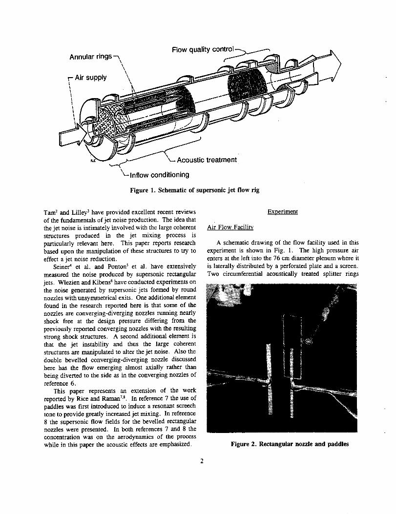
Figure 2. Rectangular nozzle and paddles

remove the upstream valve and entrance noise. The flowis further conditioned by two screens before undergoingtwo area contractions of 3.5 and 135 for the rectangular
nozzles used in this experiment. The nozzle shown in
Fig. 1 is not drawn to scale but is greatly enlarged.
Nozzles and Paddies
A close-up view of the nozzle is shown in Fig. 2. A6.4 nun microphone is seen taped to the nozzle justbehind the nozzle lip. A set of full length paddles (76
mm) are mounted in their support structure. Thisstructure has three-dimensional movement and paddle
spacing adjustment which are remotely controlled fromthe control room. On the paddle support shafts the tubingfor the total pressure taps can be seen. These pressure
taps face toward the nozzle and are flush with the flowside of the paddle. There are also strain gages mountedon the paddle support posts. These measure the axialforce on the paddles.
The five nozzle geometries tested in this program areshown in Table 1. The dimensions shown are the nozzle
exit long dimension (L), exit small dimension (_x_, andthe throat dimension (H_. Note there are three mainnozzle types: single-bevelled (3C), straight (4C, 6CD),and double-bevelled (9C, 9CD). All bevel cuts weremade at thirty (30) degrees from the exit lip. The straightand the double-bevelled types have both a convergingversion which was operated under-expanded and a
converging-diverging version which was run at designpressure ratio. All of the nozzles were made from fl0 mmcopper pipe. Internal forms were forced into the pipe asthe exterior was hammered until the form proceeded to
the proper axial location. A separate internal form witha 2.5 degree half angle was used to shape the divergingportion of the C-D nozzles. Nozzles 4C and 6CD hadfinal mill cuts applied to the internal surface at the exit toprovide more accurate dimensions. The throat and exit
TABLE 1. NOZZLE
dimensions were accurate and uniform to about 0.1 ram.
It should be noticed from the above description of the
nozzles that these are not precision polished specimens.It was felt that this level of sophistication was sufficientfor the first cut screening reported here and that anyphenomenon requiting extreme accuracy and polishedsurfaces could not be maintained in practice in an actual
engine.
Acoustic Instrumentation and Procedure
During acoustic data acquisition the nozzle wasmounted as shown in Fig. 2 in the vertical position (along
with the paddles if they were used). The microphoneshown strapped to the nozzle was removed. A 6.4 mmmicrophone with windscreen was mounted facingupstream in a three dimensional traversing mechanism.The microphone traverse was computer controlled
providing 7.62 cm increments during an axial traverse.The microphone was manually moved in the transversedirection to start a new axial traverse. In the vertical
plane (Z-X plane through the large dimension of thenozzle) axial traverses from X = -22.9 cm to +1.22 m
were performed at Z = 7.62, 10.2, 12.7, 15.2, 22.9,30.5, 38.1, 45.7, and 53.3 cm. The vertical planetraverses were conducted above the nozzle away from thefloor. In the horizontal plane (Y-X plane through thesmall dimension of the nozzle) axial traverses from X = -7.62 cm to + 1.22 m were performed at -Y = 7.62, 10.2,12.7, 15.2, 17.8, 20.3, 25.4, and 30.5 cm. The axialreference was the nozzle exit. A single microphone wasused thus eliminating the problem of differences in multi-
channel systems. The microphone was calibrated using astandard piston-phone. The aerodynamic instrumentationused in these experiments has been thoroughly discussedin reference 7.
The acoustic signal was analyzed using a digital twochannel instrument. The narrow band spectrum was
CONFIGURATIONS TESTED
NOZZLE CONFIGURATION L, nun I-Iexit, n'lnl
3C Single-Bevel, Converg. 66.0 13.5
4C Straight Exit, Converg. 65.8 13.2
6CD Straight Exit, C-D 68.1 14.1
Htlna,lnnl ASPECTRATIO
13.5 4.893
13.2 4.969
12.5 4.817
9C Double-Bevel, Converg. 64.8 13.7 13.7 4.728
9CD Double-Bevel, C-D 69.3 13.3 11.7 5.200
3

convened to 1/3 octave data using a computer. All noisedata reported here are thus 1/3 octave data except whentones may be discussed.
Acoustic Results
The results of the two experiments will now be
presented. The first set of results show the noise of thebevelled rectangular nozzles compared to the conventional
rectangular nozzles. Each comparison will be made forthe same types of nozzles (either converging orconverging-diverging). The comparisons are madebetween nozzles 9CD and 6CD, 9C and 4C, and 3C and4C (see Table 1). The acoustic data at the extreme limits
of our traversing mechanism might be considered to stillbe near-field (25 to 100 times the nozzle smalldimension), but it should be sufficiently close to far-fieldto be used at least for comparative purposes.
The second phenomenon of induced screech using theconventional converging-diverging rectangular nozzle(6CD) will then be presented. The results will show theeffect on the jet mixing and the jet mixing noise sourcelocation. The acoustic data will be very near-field sincethis induced screech mixing method would most likely beused within the shroud of a mixer-ejector system and onlyin such a system would there be an acoustic advantage
using this mixing enhancement method.
Acoustic Benefit of Bevelled Nozzles
The evaluation of the acoustic benefit of bevelled
nozzles is quite a complex process since the benefit issituation or hardware dependent. For example, it will beshown below that a bevelled rectangular nozzle withsupersonic flow operated out in the open is noisier than itsbaseline counterpart because it produces about anadditional ten decibels of very high frequency broadband
Y-O. Z-45.7 cm, ZIHna=34.5
> 110 "
= • :_.z a _ ---e- -2zs -182w ir._r..m ._..ra..Q "_"" "'{D'" 0 0G: . uJ .-._-.- 22.9 16,2
_ --e- ..8 _.s--_ 90 _/ ---0 .... S4.4 64.8O --B-- 114.3 80.8(/)
1/3 ocTAVE FREQUENCY, KHZ
Figure 3. Noise spectra for nozzle 6CD, Mexp = 1.395, sideline
plane of large nozzle dimension, 45.7 cm from axis
noise near the plane of the nozzle exit. However if thisnozzle is enclosed in a properly designed acousticallytreated shroud as in a mixer ejector, this excess noisedoes not present a problem. We will attempt to showhere that the bevelled nozzle provides a noise directivityand spectrum shift that can be beneficial if the system isproperly designed. The noise directivity shift is precisely
the property mentioned in the Introduction section whichhas been sought to render the mixing noise moreamenable to attenuation by acoustic liners. A completeanalysis of the acoustic benefits of the bevelled nozzle is
beyond the scope of this paper, but some of the acousticelements which must be considered in such an analysiswill be discussed.
The measured noise spectra for the baseline C-Dnozzle 6CD are shown in Fig. 3. All of the data are fora constant distance sideline of 45.7 cm from the nozzle
axis in the plane of the large nozzle dimension. Sevenequally spaced axial positions are shown from behind thenozzle plane (-22.9 era) to quite far downstream from thenozzle (114.3 era). For later more detailed analysis,twenty positions spaced at 7.6 cm are available but theywould unnecessarily clutter the graph. As would beexpected, near the nozzle exit plane the noise spectra isdominated by very high frequency noise. As themicrophone is moved downstream, the mixing noisecentered at 2.5 kHz becomes dominant and is seen to
peak somewhere between 68 and 94 cm (actually 84 cm)at a level of 121.1 dB.
The noise spectra for the double bevelled C-D nozzle9CD measured at the same sideline positions are shown inFig. 4. The very noticeable difference in these spectrafrom those of Fig. 3 is the nearly ten decibel increase inthe very high frequency noise mainly near the plane of thenozzle. It is tempting to attribute this high frequencynoise increase to shock associated broadband noise as
presented by Tam and Tanna 9 and Tam 1°et al. since the
: 120 Y =0. Z-45.7 cm, Z/Ho_ar_4.3 n..r:l.
-0o. _.:t,-::_,S_2_-?> 110
..._Z._. __._._._.._'. "
_0,,, ..._._:._e," ...a.-. o o-" l-.,,,w.._..._,_,.:,_p_ .-__-.-22.9 17.IO.o -___.o"'_ "_ ---_-. 4s.:Z _ --_-- 68.6 51.4
"_ 90 _ .-.e .... 94.4 s&eO ---I-- _ _ 4._ 8s.7¢O
1/3 ocTAV| =FREQUENCY, KHZ
Figure 4. Noise spectra for nozzle 9CD, Mexp = 1.425, sideline
plane of large nozzle dimension, 45.7 cm from axis
4
125
.Jtll
m .£3..o..E_.E].. _
120 _zr.__._. _. c_.E]"
,,, _,z_..-"_ ._' _ --I
" ?_ -"1..._m 110tu¢ _'E] ''D.E3]' f F, HZ --'l'l
,-in" I2" H _ 16oo,', 105 .J_ ,-.G.-.- 250O
z o_ -0,- 4000' Y-0, ZI45.7 CM, _32.3 --I-- 12500
100 ..... ' ' ' '3_0 ' _ ...... ' ' ' ' ' '-20 -10 0 10 20 40 50 60 70 80 90
AXIAL DISTANCE FROM NOZZLE EXIT, X/I-bxlt
Figure 5. Axial distribution of sound pressure level, sideline Z=45.7 cm
Nozzle 6CD, Idexp=1.395
frequency relationship to mixing noise is about correct.
However, this jet is properly expanded and does not have
sufficiently strong shocks to sustain a significant screechtone even near the nozzle lip (about 138 dB). It is
possible that the oblique bevel of this nozzle exit has
promoted the dominance of oblique instability modeswhich was the reasoning behind trying such a nozzle.
The source of this high frequency noise is unknown at
present. As mentioned earlier, this high level noise
dominates the spectrum only near the plane of the nozzle
where it would experience nearly normal incidence onto
an acoustic liner in a properly designed shrouded mixer-
ejector. It is thus of no consequence for the purposes of
this study but could pose a problem for other
configurations.Other characteristics of the nozzle 9CD noise spectra
can be seen in Fig. 4. The mixing noise peak has shifted
to a higher frequency of 4 kHz. The peak occurs at X =68.6 cm at a level of 116.9 dB. The reduction in the
peak mixing noise level from 121.1 to 116.9 dB
represents an obvious advantage for the bevelled nozzle.However, the shift in the location of this peak from 84 cm
> 115
WI¢'-'1
or"0.
¢"1Z
mm_ 125 I'i'I'I"'I
120 _
e;
._ .__.._.-._ EI. P--_ ,a_-_'2_N'_._
110 __.t_--_" O.._3._3-_ f F. HZ --i-_r._
.D.._z.r ,600105 '2' _- .-.E}-- 2500
_ _ --_'-- 4000
__r_-o,z-45.7,Z/I-k_34.2 --B-- 12500
100 ",r_ . , . , , _ , , , _ _ . , . , , , , , ,-20 -10 0 10 20 30 40 50 60 70 80 90
AXIAL DISTANCE FROM NOZZLE EXIT, Xll-le_
Figure 6. Axial distribution of sound pressure level, sideline Z=45.7 cm
Nozzle 9CD, _1.425
to 69 cm represents another advantage for the bevelled
nozzle which is not quite so obvious. The upstream
location of the peak means that the noise must propagate
a longer distance to reach the end of a given mixer-ejector
system and in addition could be propagating at a larger
angle to the jet axis. If used in conjunction with a
properly designed and located acoustic liner in a shrouded
configuration, the more normal angle of incidence of thenoise on an acoustic liner will provide improved acoustic
suppression for a given liner length.
Cross plots of the data in Figs. 3 and 4 are shown in
Figs. 5 and 6. The latter plots show the direetivity
information more clearly and are simplified by using only
representative frequencies. The peak frequencies of the
mixing noise, 2500 Hz and 4000 Hz, for the two nozzlesare retained. The one-third octave band at 12,500 Hz is
used as representative of the high frequencies withoutcontamination from screech tones or harmonics where
they occur. The 1600 Hz band represents broadband
noise below the mixing noise peaks for any of the nozzlesstudied here. The bands at 5,000 Hz and 10,000 Hz wereavoided to eliminate the screech tone and harmonic when
they occurred (underexpanded converging nozzles).
Bevelling the nozzles when screech occurs produces very
large screech level reductions but this was not the
emphasis of this study.The same noise characteristics discussed relative to
Figs. 3 and 4 can be seen more clearly in Figs. 5 and 6.In addition the difference between the noise level curves
in Figs. 5 and 6 are plotted in Fig. 7 which provides a
good condensation of the acoustic differences betweennozzles 9CD and 6CD. The large increase in high
frequency noise is evident near the plane of the nozzle
and the jet mixing noise reduction is evident in the downstream direction. This sound pressure level difference
format will be used to present the results for the
remainder of the nozzle configurations. The frequencies
10 F,HZ-..o.--- 1600
I'I'I .-.E}-,- 2500
i /,,'d, , -,,,,- 40o0• --I-- 12500
0.i _ i.i_i I
"I .... i _ m.I "D
Z 0 _I--l--I--I I --i- --
o -5
•_V_L _C-,ING-OIVERGING _._._._ G
Y-O; Z-45.7 CIM
"10.20 '.1' 0 ' _ '110 ' _lg ' 310 ' 40 ' frO " 60 " ;0 ` _tO ' _0 '
AXIAL DISTANCE FROM NOZZLE EXIT, X/l'knm
Figure 7. Sound pressure level difference, sideline Z-45.7 cm
SPLNOTamo- SPI._oz.SCD,design pressures

at the peaks of the mixing noise remained at 2500 Hz and4000 Hz for the straight and bevelled nozzles for all of
the configurations.The acoustic influence of using a double bevelled exit
with a converging rectangular nozzle operating
underexpanded is summarized in Figure 8. The largeincrease in the sound pressure level ,SPL, at high
frequencies near and ahead of the plane of the nozzle exitis again evident. The very large reduction, nearly 12 dB,in mixing noise at 2500 Hz in the far downstreamdirection is evident. However, now a 5 dB increase in
mixing noise at 4000 Hz is seen. This is mainly due toa large upstream directivity shift and high frequency shiftof the mixing noise for the double bevelled nozzle. Anacoustic liner would have to absorb this 5 dB hump to
make this geometry effective. This may be quite possibledue to the upstream directivity shift of the noise.
The final bevelled nozzle geometry is the single
bevelled converging nozzle, 3C. The acoustic data forthis nozzle are compared to the standard straight exitconverging nozzle, 4C, in Fig. 9. The data were takenon the bevelled side (higher SPL side) of thisunsymmetrical nozzle. Again the high frequency SPLincrease is evident near the plane of the nozzle and
substantial mixing noise reductions are evident in thedownstream direction.
It is evident from the acoustic data presented above
that all jets from the bevelled rectangular nozzles havesome common properties. All had large increases in highfrequency noise near the plane of the nozzle. This shouldnot be a big problem when an acoustically lined duct canbe used around the jets because of the upstream positionand normal to the wall directivity of the source. All
geometries had reductions in the level of the mixing noiseat far downstream positions and a shift to higher
frequency at the peak. A more detailed study must bemade to determine how to best take advantage of these
10 - F, HZ
:ii. 1 --e-- 16oom ,-.El-.- 2500
"l- I _ --/_-- 4000
i 5 ", ,z.:_..T_, --=-- 12500
o - _=-'_-.!._ JL_ _ _Z _ -- U _J_IP"_ "_ I-U-I
=: ,E)...Ey"ET -
#- DOUB.E _ CONV_eNG _'__Z.m -1 0 Y-0, Z-4S.70g ,E]...E)..E],.i3
, i , f i I , i , _ , i , i , i ' 710 " i , i ,-20 -10 0 10 20 30 40 50 60 80 90
AXIAL DISTANCE FROM NOZZLE EXIT, X/H_
Figure 8. Sound pressure level difference, sideline Z=45.7 cm
SPLNOZ.gC- SPI.Noz.4c, design pressures
properties when a bevelled nozzle might be used withacoustic treatment on the walls of a mixer-ejector system.
Aerodynamic Properties of Bevelled Nozzles
The supersonic jet flow field from bevelled rectangularnozzles was the subject of the study reported in reference8. All of this information is not repeated here, but someflow properties can be summarized which are useful in thecurrent discussion. Jets from bevelled convergingrectangular nozzles are deflected from the axial directiondue to the transverse pressure gradient present at thebevelled exit. This property was also evident in the roundjets reported by Wlezien and Kibens6. The singlebevelled nozzle flow diverts unsymmetrically from theaxis. The double bevelled nozzle flow spreads
symmetrically about the jet axis and was observed toproduce increased mixing over the other geometries asmeasured by mass entrainment. This nozzle might be anexcellent choice for some applications which areconsistent with these flow properties. The doublebevelled converging-diverging rectangular nozzle produces
a-jet with very little divergence over that of the straightexit CD nozzle. This is probably due to the inability ofthe transverse pressure gradient to exert an influenceacross the supersonic flow in the diverging nozzle exit.
Acoustic Propagation Angle
The upstream shift in the axial position of the peak inthe mixing noise of the jets from the bevelled nozzles isbeneficial if acoustic linings are to be used in the duct ofa mixer-ejector system. It is of interest to determine ifthe upstream shift was caused by an upstream shift in thesource location or by an increase in the radiation angletoward the sideline. To study this effect in anapproximate manner the acoustic data was analyzed in the
10[i F. I-[Z"I'I'I _ 1600
m 5 --_-- 4000-- --I-- 12500OI,LI
-=#- s_.E BEVEL CONVERCa_G _-¢0
_'"E}..G 1_,_-10 y-o, Z-45.7 CId
-2o'-;oo;o 3'o40so;o ;o io,oAXIAL DISTANCE FROM NOZZLE EXIT, X/Hex=t
Figure 9. Sound pressure level difference, sideline Z=45.7 cm
SPI.Noz.ac - SPLNoz.4c, l_xp=1.40
=2N
X
NNOZ
it
t5iiiOZ
I-
3O
2O
10
40 CONV_GING-IZVERGING NOZZLES ."_11DESIGN PRESSURE .." ,,--/
LINES ARE REGRESSION UNES ..r'l, ,_//.J
NOZ."" --0"- 0C0 2500
-..o.. god 4000n" o'7-
If:;:"" .-.e-.- 6130 2500---IB-- 6C0 4000
°o ;o '2'0 3'0','o' s'o'io '7'0DISTANCE FROM NOZZLE EXIT, X/Hex_
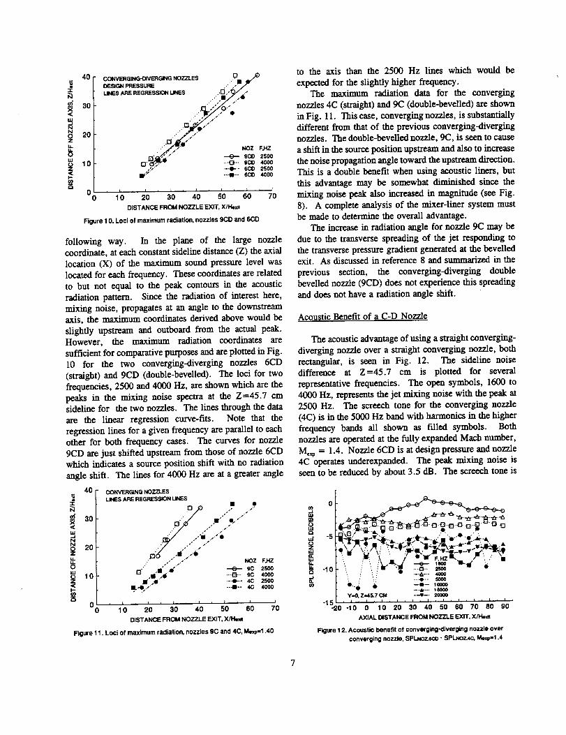
Figure 10. Loci of maximum radiation, nozzles 9CD and 6CD
following way. In the plane of the large nozzlecoordinate, at each constant sideline distance (Z) the axial
location (X) of the maximum sound pressure level was
located for each frequency. These coordinates are related
to but not equal to the peak contours in the acoustic
radiation pattern. Since the radiation of interest here,
mixing noise, propagates at an angle to the downstreamaxis, the maximum coordinates derived above would be
slightly upstream and outboard from the actual peak.However, the maximum radiation coordinates are
sufficient for comparative purposes and are plotted in Fig.I0 for the two converging-diverging nozzles 6CD
(straight) and 9CD (double-bevelled). The loci for two
frequencies, 2500 and 4000 Hz, are shown which are the
peaks in the mixing noise spectra at the Z=45.7 cmsideline for the two nozzles. The lines through the data
are the linear regression curve-fits. Note that the
regression lines for a given frequency are parallel to eachother for both frequency cases. The curves for nozzle
9CD are just shifted upstream from those of nozzle 6CDwhich indicates a source position shift with no radiation
angle shift. The lines for 4000 Hz are at a greater angle
40 _C._N@ NOZZLESLINES ARE REGRESSION LINES
•-r • •
)"l /, • ,P'
X<:
o . /;. /;,
it NOZ F,I-IZ
=_ f:1"'"'" .'"i_""" _ 9C 2500
0 10 ,I A_ ..._.. 9c 4oooz j ,@ [email protected] 4c 2500
• , • --i-- 4c 4000¢0
O
°o ,'o ;o ,'o s'o6'0;0DISTANCE FROM NOZZLE EXIT, X/Ite_
Figure 11. Loci of maximum radiation, nozzles 9C and 4C, Mexp=1.40
to the axis than the 2500 Hz lines which would be
expected for the slightly higher frequency.The maximum radiation data for the converging
nozzles 4C (straight) and 9C (double-bevelled) are shown
in Fig. 11. This case, converging nozzles, is substantiallydifferent from that of the previous converging-divergingnozzles. The double-bevelled nozzle, 9C, is seen to cause
a sl_ft in the source position upstream and also to increase
the noise propagation angle toward the upstream direction.This is a double benefit when using acoustic liners, but
this advantage may be somewhat diminished since the
mixing noise peak also increased in magnitude (see Fig.
8). A complete analysis of the mixer-liner system mustbe made to determine the overall advantage.
The increase in radiation angle for nozzle 9C may be
due to the transverse spreading of the jet responding to
the transverse pressure gradient generated at the bevelledexit. As discussed in reference 8 and summarized in the
previous section, the converging-diverging doublebevelled nozzle (9CD) does not experience this spreading
and does not have a radiation angle shift.
Acoustic Benefit of a C-D Nozzle
The acoustic advantage of using a straight converging-
diverging nozzle over a straight converging nozzle, both
rectangular, is seen in Fig. 12. The sideline noisedifference at Z=45.7 cm is plotted for several
representative frequencies. The open symbols, 1600 to
4000 Hz, represents the jet mixing noise with the peak at2500 Hz. The screech tone for the converging nozzle
(4C) is in the 5000 Hz band with harmonics in the higher
frequency bands all shown as filled symbols. Both
nozzlesare operatedatthe fullyexpanded Mach number,
M=_p = 1.4. Nozzle 6CD isatdesignpressureand nozzle
4C operatesundcrexpanded. The peak mixing noiseis
seen tobe reducedby about 3.5 dB. The screechtoneis
_IiiimOIAI
idOZtU
IMitItO
', . ; X _. ) m F. HZ m. /'.. ,' •
,.., _ -=- ,oooo.... &--.. 160O0
..-¢z... = ,--..-; .o .0"1 5 ' ' ' , I , , , I , I , I , I ,
-20 -10 0 10 20 30 40 50 60 70 80 90
AXIAL DISTANCE FROM NOZZLE EXIT, Xll-bxm
Figure 12. Acoustic benefit of converging-diverging nozzle over
converging nozzle, SPI.No7 _o - SPLNoz_ Mexp-t .4

=K
N
X<l&J
N0Z
E
.<
15
10
- (
NOZZLE C-D noz.z_, Mex_1.395, ! - 2500 Hz
-_ ,_o? ....................0 5 10 15 2.0 25
AXIALDISTANCEFROMNOZZLEEXIT,X/I-i_
Figure 13. Near-field noise measurements, nozzle 6CD, no paddles
seen to be reduced by nearly 13 dB near the nozzle plane
and the higher frequency harmonics likewise experience
significant reductions.
Induced Screech and Near-Field Jet Noise
In thissectionthe effecton jet mixing noise from
high levelsof induced screechexcitationwillbe shown.
The paddies as shown in Fig. 2 are inserted into the shear
layers on the long sides of the nozzle. The paddies take
the place of shocks in the feedback loop and it is because
of thisanalogythatthe "inducedscreech"terminologyis
used here. The induced screechlevelat the nozzlelip
increasesfrom 142 to 157.8dB usingthelongestpaddies
for the insertion used in this experiment. The jet
experiences a violent flapping mode when excited by theinduced screech. This is clear from the Schlieren
photographs reported in reference 7. Large nonlinear (not
sinusoidal) wave amplitudes were seen to be excited
which caused the jet to alternately impinge upon the
paddies producing large oscillating pressures on the
paddles. The paddies appeared to be acting as a simplesource as suggested by Powell" for higher speed flows.
The forces on the two paddies were out of phase which
5 S
0 5 1 0 1 5 20 25 30
AXIAL DISTANCE FROM NOZZLE EXIT, X/I-le_
Figure 14. Nelu'-f'mld noise measurements, nozzle 6CD, long paddles
was required to sustain the flapping instability of the jet.
As the oscillating flow passed the paddies large oscillatingvorticity was imparted on the flow which sustained the
increased mixing downstream from the paddles. A
complete discussion of the mixing enhancement of the jetcan be found in reference 7.
The 1/3 octave noise near-field produced by the
conventional convergent-divergent rectangular nozzle
(6CD) operated at design pressure without paddies is
shown in Fig. 13. The nozzle profile is shown to scale at
the lower left side of the figure. Some interesting
features of the noise field should be pointed out. Very
near to the jet flow, where the constant noise contours are
almost parallel to the jet, the oscillating pressure is caused
by the potential field of the passing large coherent
structures. In Fig. 13, the coherent structures passing at
2500 Hz are seen to peak at an axial location of about
twenty times the nozzle small dimension (X/I-I_ t = 20).
This peak location is an average value since the unsteady
pressure is averaged over one hundred samples by the
digital spectral analyzer. Further from the nozzle axis the
coherent structure potential field falls off rapidly, as seen
by the tight contour spacing near the jet, and the radiated
acoustic field becomes more dominant. For a fairly
highly directional noise source, a lobed pattern of the
contours becomes apparent. This lobed pattern will
become more obvious in the next figure as the radiation
lobe is brought into the field of view.
In Fig. 14 the noise near-field is shown for nozzle
6CD when the full length paddies (76.2 ram) are installed
to induce screech and increase jet mixing. Again the
nozzle and paddies are shown to scale at the lower left of
the figure. The coherent structures are seen to peak out
at X(I-l_at = 12 to 13, a significant reduction from the
value of 20 for the unexcited jet. The lobed pattern of thenoise radiation is now seen at the lower right of the
figure. The paddles have thus moved the jet mixing and
the jet noise radiation source nearer to the nozzle exit.
The mixing enhancement has been inferred here from the
noise near-field but this really just agrees with the
aerodynamic data for this configuration documented inreference 7.
The noise difference for nozzle 6CD with and without
the paddles is shown in Fig. 15 for the Z=45.7 cm
sideline in the plane of the large nozzle dimension. The
open symbols represent the jet mixing noise and the filled
symbols the induced screech and harmonics. For this
analysis the screech is included since it is produced by the
paddles and must be weighed in any noise comparison.
For this data, at least approximating the far-field, the
noise increase due to the paddies does not look promising.
The jet mixing noise has increased by about 3 dB and the
8

F. HZ
20 - _ 16oo
i e _ .-._.- 2r_o• _ ", --,_-- 4000
u_ • ', i ', -.._- sooo15 ." _ , ', .... l-.- 10oo0 .m..
- • , / '.l .an - .11"_.'al-.llo - HI" _ F'.._.JI ,e I "11 m IIJr' / "_,"ELI • = L el ...t i ,., / L. "_ _ ,
10 - :"L / .i" J. .•-_ll"l L "'.,t_ •x J'
Z , __ O-Q_q " •uJ" 5- ,t_
o
-5 ' : i ...... , . , , , ,-20 -10 0 10 20 30 40 50 60 70 80 90
AXIAL DISTANCE FROM NOZZLE EXIT, X/l%xe
Figure 15. Sound pressure level difference, sideline Z=45.7 cm
Nozzle 6CD, SPL.kmo paddl_ - SPLno pado_., Moxp-1.40
induced screech and its harmonic has about a 10 dB
increase even at the downstream locations. The contour
plots of Figs. 13 and 14 showed the mixing enhancementbenefit using the paddies, but this benefit is lost in the far-
field. Recall that the stated application of interest here is
an acoustically lined mixer-ejector system and the very
near-field behavior is most important. The noise
difference in the very near field due to using paddies andinduced screech with nozzle 6CD is shown in Fig. 16.
Notice that the large increases in sound pressure level
occur ahead of the paddies which are located at
X/H_it=7.2. At the higher axial distances all of the SPL
levels are falling off. This very near field has a very
complex structure with any measurement being a mixture
of propagating sound and coherent structure potential field
moving at convective velocity. The SPL levels at leastahead of the nozzle exit are probably dominated by
acoustic propagation while the downstream values may be
F. HZ
25 .,,e ..... ..e _ lsoo
m 20 -'" _ .-E3-.- 2500e" _"o ..... -41 --_- 4000--.O-- 5000
no 1 5 Ji .................• ............ _ .....I}.-. 1 0000"!!
Ill ..." ." ram" -_t._.--_ _ .....• ....
___'i_ .i .....
i 10 _r.---_--:---_.-'-_ ,_"'_'_-.._:m, ..................... •5 _ ",,7__ -.
u,. 0 PADDLE \ ' -..
| ........-1 0 Y-0 Z-7.62 CM. Z/Plmm-5.39 _/
-1 5 -1 0 -5 0 5 1 0 1 5 20
AXIAL DISTANCE FROM NOZZLE EXIT, X/I_
Figure 1 6. Sound pressure level difference, very near-field, Z=7.62 cm
Nozzle 6CD, SPLk_ pa_k_" SPI.._o pa_a, M_xp=1.40
potential field dominated. From Figs. 13, 14, and 16 it
appears that the enhanced mixing due to the inducedscreech of the paddles has moved the action upstream and
it just might be possible to exploit this situation using
properly designed acoustic treatment.
Concluding Remarks
Two very different jet noise reduction concepts have
been presented in this paper. The first concept uses abevelled exit for a rectangular nozzle producing a
supersonic jet. Converging-diverging and divergingnozzles were tested. Both single (unsymmetrical) and
double bevelled (symmetrical) cases were used. The
double bevelled CD nozzle showed clear advantages over
that of a straight exit CD nozzle. A 4.2 dB reduction in
jet mixing noise level was observed. All of the bevellednozzles tested showed a jet mixing noise spectral shift to
higher frequency and an upstream location shift. Thelocation shift could be due to upstream source noise
location and/or radiation angle increase both being
advantageous when wall acoustic treatment is used. All
bevelled geometries produced a large increase in high
frequency noise but it was mainly near the plane of thenozzle and could thus be easily absorbed by wall
treatment.
The second concept, the use of screech inducing paddies
with the supersonic rectangular jet of a converging-
diverging nozzle operated at design pressure may beuseful for internal use in an acoustically treated mixer-
ejector nozzle system. The jet mixing was shown toincrease dramatically moving the jet noise source location
back toward the mixer nozzle lip. This provides a longer
acoustic path length for the internal mixing noise as it
passes through the acoustically treated duct section. Far-field noise analysis showed a substantial increase in jet
mixing noise and of course in induced screech level.
Very near-field analysis showed that the noise sourceincreases were confined near the nozzle exit and the
screech inducing paddle location. It is possible that
properly designed acoustic treatment might take advantage
of this upstream source shift.
Additional study should be conducted on both of these
concepts. Only a single bevel angle, 30 degrees, has been
tried. The study has been limited to a fully expandedMath number of 1.4. For the screech inducing paddies,
drag losses must be minimized while retaining mixing
enhancement and a more upstream directed screech noisefield would be beneficial. For all of the above, the
influence of confining walls and acoustic treatment mustbe studied.

.
.
.
.
.
.
.
.
.
10.
References
Seiner, J.M., and Krejsa, E.A., "Supersonic Jet
Noise and the High Speed Civil Transport," AIAA
Paper No. 89-2358, July 1989.
Tam, C.K.W., "Jet Noise Generated by Large-Scale
Coherent Motion," Aeroacoustics of Flight Vehicles:
Theory and Practice, Vol. I: Noise Sources, NASA
RP 1258, WRDC TR 90-3052, Aug. 1991, pp. 311-
390.
Lilley, G.M., "Jet Noise Classical Theory and
Experiments," Aeroacoustics of Flight Vehicles:Theory and Practice, Vol. 1: Noise Sources, NASA
RP 1258, WRDC TR 90-3052, Aug. 1991, pp. 211-289.
Seiner, J.M., Ponton, M.K., and Manning, J.C.,
"Acoustic Properties Associated with Rectangular
Geometry Supersonic Nozzles," AIAA Paper No.
86-1867, July 1986.
Ponton, M.K., Manning, J.C., and Seiner, J.M.,
"Far-Field Acoustics of Supersonic Rectangular
Nozzles with Various Throat Aspect Ratios," NASA
TM 89002, 1986.
Wlezien, R.W., and Kibens, V., *The Influence of
Nozzle Asymmetry on Supersonic Jets," MDRL 86-
2, also presented at the AIAA 24th Aerospace
Sciences Meeting, Reno, Nevada, 6-8 January 1986.
Rice, E.J., and Raman, G., *Enhanced Mixing of a
Rectangular Supersonic Jet by Natural and Induced
Screech," AIAA Paper No. 93-3263, July 1993.
Rice, E.J., and Raman, G., "Supersonic Jets From
Bevelled Rectangular Nozzles," accepted for
presentation at the Winter Annual Meeting of the
ASME, Symposium on Flow Acoustics Interactionand Fluid Control, November 28-December 3, 1993,
New Orleans, La.
Tam, C.K.W., and Tanna, H.K., "Shock Associated
Noise of Supersonic Jets from Convergent-DivergentNozzles," Journal of Sound and Vibration, Vol. 81,
No. 3, pp. 337-358, 1982.
Tam, C.K.W., Seiner, J.M., and Yu, J.C.,
"Proposed Relationship Between Broadband ShockAssociated Noise and Screech Tones," Journal of
11.
Sound and Vibration, Vol. 110, No. 2, pp. 309-321,1986.
Powell, A., "On the Edgetone," The Journal of the
Acoustical Society of America, Vol. 33, No. 4,
April 1961, pp. 395-409.
10


FormApprovedREPORT DOCUMENTATION PAGE OMBNo.0704o0188
Public repotting burdenfor this ¢oflectionof informationis estimated to average 1 ho_r per response. Includingthe time/or reviewing_, searchingexisting data sources,gatharingand maintainingthe _ata needed, and completingand reviewingthe collectionof information. Send comments regardingthis bur0en _'timate or any other aspect of thiscofioclionof information,includingsugg_ for reduong this burden, to WashingtonHeaclquarmrsServices, Directoratefor Informa_onOperations and Re_, 1215 JeffersonDavis H_hway, Suite 1204, Arlington, VA 22202-4302, and to the Offce of Management and Budget, PaperworkReductionProiect (0704-0188), Wasl_ngton,DC 20503.
1. AGENCY USE ONLY (Leave b/ank) 2. REPORT DATE 3. REPORT TYPE AND DATES COVERED
October 1993 Technical Memorandum
4. TITLE AND SUBTITLE 5. FUNDING NUMBERS
Mixing Noise Reduction for Rectangular Supersonic Jets by Nozzle
Shaping and Induced Screech Mixing
e. AUTHOR(S)
Edward J. Rice and Ganesh Raman
7. PERFORMINGORGANIZATIONNAME(S)ANDADDRESS(ES)
National Aeronautics and Space AdministrationLewis Research Center
Cleveland, Ohio 44135-3191
9. SPONSORING/MONITORINGAGENCYNAME(S)ANDADDRESS(ES)
National Aeronautics and Space Administration
Washington, D.C. 20546-0001
WU-537-02-22
8. PERFORMING ORGANIZATION
REPORT NUMBER
E-8165
10. SPONSORING/MONITORINGAGENCY REPORT NUMBER
NASA TM- 106364AIAA-93-4322
11. SUPPLEMENTARY NOTES
Prepared for the 15th AIAA Aeroacoustics Conference sponsored by the American Institute of Aeronautics and Astronautics, Long Beach.
California, October 25-27, 1993. Edward J. Rice, Lewis Research Center and Ganesh Raman, Sverdrup Technology, Inc., Lewis Research Center
Group, 2001 Aerospace Parkway, Brook Park, Ohio 44142 (work funded by NASA Contract NAS3--?..5206). Responsible person, Edward J. Rice,
(216)43_-_07.12" DISTRIBUTION/AVAILABILITY STATEMENT
Unclassified - Unlimited
Subject Category 02
12b. DISTRIBUTION CODE
13. ABSTRACT (Maximum 200 words)
Two methods of mixing noise modification were studied for supersonic jets flowing from rectangular nozzles with
an aspect ratio of about five and a small dimension of about 1.4 cm. The first involves nozzle geometry variation
using either single (unsymmetrical) or double bevelled (symmetrical) thirty degree cutbacks of the nozzle exit.
Both converging (C) and converging-diverging (C-D) versions were tested. The double bevelled C-D nozzle
produced a jet mixing noise reduction of about 4 dB compared to a standard rectangular C-D nozzle. In addition
all bevelled nozzles produced an upstream shift in peak mixing noise which is conducive to improved attenuation
when the nozzle is used in an acoustically treated duct. A large increase in high frequency noise also occurred near
the plane of the nozzle exit. Because of near normal incidence, this noise can be easily attenuated with wall
treatment. The second approach uses paddles inserted on the edge of the two sides of the jet to induce screech and
greatly enhance the jet mixing. Although screech and mixing noise levels are increased, the enhanced mixing
moves the source locations upstream and may make an enclosed system more amenable to noise reduction usingwall acoustic treatment.
14. SUBJECT TERMS
Jet mixing; Jet noise; Enhanced mixing; Induced screech; Edge tones; Rectangular jet;
Converging-diverging nozzle
17. SECURITY CLASSIFICATION
OF REPORT
Unclassified
18. SECURITY CLASSIFICATION
OF THIS PAGE
Unclassified
19. SECURITY CLASSIFICATION
OF ABSTRACT
Unclassified
15. NUMBER OF PAGES
1216. PRICE CODE
A03
20. UMITATION OF ABSTRACT
NSN 7540-01-280-5500 Standard Form 298 (Rev. 2-89)
by ANSI Std. Z39-18296-102