Mississippi Standard Specifications for State Aid Road and Bridge ...
793
STATE AID 2004 STATE AID 2004 STATE AID 2004 STATE AID 2004 MISSISSIPPI STANDARD SPECIFICATIONS FOR STATE AID ROAD AND BRIDGE CONSTRUCTION OFFICE OF STATE AID ROAD CONSTRUCTION MISSISSIPPI DEPARTMENT OF TRANSPORTATION JACKSON, MISSISSIPPI 2004 EDITION
Transcript of Mississippi Standard Specifications for State Aid Road and Bridge ...

STATE AID 2004 STATE AID 2004
STATE AID 2004 STATE AID 2004
MISSISSIPPI
STANDARD SPECIFICATIONS
FOR
STATE AID ROAD AND BRIDGE CONSTRUCTION
OFFICE OF STATE AID ROAD CONSTRUCTION
MISSISSIPPI DEPARTMENT OF TRANSPORTATION
JACKSON, MISSISSIPPI
2004 EDITION

STATE AID 2004 STATE AID 2004
STATE AID 2004 STATE AID 2004
STATE AID 2004 STATE AID 2004
STATE AID 2004 STATE AID 2004
MISSISSIPPI
STANDARD SPECIFICATIONS
FOR
STATE AID ROAD AND BRIDGE CONSTRUCTION
BOOK NO.
APPROVED AND ADOPTED
BY
THE OFFICE OF STATE AID ROAD CONSTRUCTION
MISSISSIPPI DEPARTMENT OF TRANSPORTATION
JACKSON, MISSISSIPPI
July1, 2004

STATE AID 2004 STATE AID 2004
STATE AID 2004 STATE AID 2004
STATE AID 2004 STATE AID 2004
STATE AID 2004 STATE AID 2004
STATE AID
STANDARD SPECIFICATIONS
Edition of 2004
In compliance with Section 65-9-11, MISSISSIPPI CODE 1972, Annotated, the
State Aid Engineer has caused to be revised and updated the Standard Specifications for
State Aid Road and Bridge Construction. The best practices governing road and bridge
construction have been followed and every effort has been made to provide specifications
that are in keeping with expected traffic demands and needs on County Roads on the State
Aid System, so that the most miles of roads and bridges may be constructed with available
funds.
These revised specifications, designated as the 2004 Edition, are hereby adopted
as the Mississippi Standard Specifications for State Aid Road and Bridge Construction.
J. Brooks Miller, Sr.
State Aid Engineer
July 1, 2004

STATE AID 2004 STATE AID 2004
STATE AID 2004 STATE AID 2004
STATE AID 2004 STATE AID 2004
STATE AID 2004 STATE AID 2004i
TABLE OF CONTENTS
SECTION S-100 - GENERAL PROVISIONS
Section Page
S-100 - GENERAL PROVISIONS 1-1
S-101 - DEFINITIONS AND TERMS 1-1
S-102 - BIDDING REQUIREMENTS AND CONDITIONS 1-14
S-103 - AWARD AND EXECUTION OF CONTRACT 1-21
S-104 - SCOPE OF WORK 1-25
S-105 - CONTROL OF WORK 1-31
S-106 - CONTROL OF MATERIALS 1-44
S-107 - LEGAL RELATIONS AND RESPONSIBILITY TO PUBLIC 1-50
S-108 - PROSECUTION AND PROGRESS 1-68
S-109 - MEASUREMENT AND PAYMENT 1-78
S-110 - REQUIRED CONTRACT PROVISIONS 1-91
S-111 thru S-199--Blank 1-92
FIGURE - 1. PAVEMENT STRUCTURE 1-93
SECTION S-200 - EARTHWORK
S-200 - MOBILIZATION 2-1
S-201 - CLEARING AND GRUBBING 2-2
S-202 - REMOVAL OF STRUCTURES AND OBSTRUCTIONS 2-5
S-203 - EXCAVATION AND EMBANKMENT 2-8
S-204 - Blank 2-21
S-205 - SUBGRADE PREPARATION 2-22
S-206 - STRUCTURE EXCAVATION FOR CULVERTS,BOXES AND MINOR STRUCTURES 2-24
STATE AID 2004 STATE AID 2004
STATE AID 2004 STATE AID 2004ii
Section Page
S-207 - Blank 2-26
S-208 - LINEAR GRADING 2-27
S-209 - Blank 2-29
S-210 - ROADSIDE DEVELOPMENT - GENERAL PROVISIONS 2-30
S-211 - TOPSOILING 2-31
S-212 - GROUND PREPARATION AND FERTILIZER 2-35
S-213 - Blank 2-37
S-214 - SEEDING 2-38
S-215 - MULCHING 2-42
S-216 - thru S-225 - Blank 2-44
S-226 - SOLID SODDING 2-45
S-227 - EXCELSIOR BLANKET 2-48
S-228 - Blank 2-49
S-229 - PAVED DITCHES 2-50
S-230 - BITUMINOUS TREATED ROVING 2-52
S-231 - EROSION CONTROL FABRIC 2-54
S-232 - GEOTEXTILE FABRIC STABILIZATION 2-56
S-233 - TEMPORARY SILT FENCE 2-58
S-234 - Blank 2-60
S-235 - TEMPORARY EROSION CHECKS 2-61
S-236 - TEMPORARY SILT BASINS 2-62
S-237 - thru S-238 - Blank 2-63
S-239 - TEMPORARY SLOPE DRAINS 2-64
STATE AID 2004 STATE AID 2004
STATE AID 2004 STATE AID 2004iii
Section Page
S-240 - GEOGRID REINFORCEMENT OF EMBANKMENT SLOPES AND SUBGRADES 2-66
S-241 - thru S-299 - Blank 2-68
SECTION S-300 - SUBBASES AND BASES
S-300 - SUBBASES AND BASES 3-1
S-301 - thru S-303 - Blank 3-1
S-304 - GRANULAR COURSES 3-2
S-305 - and S-306 - Blank 3-7
S-307 - LIME TREATED COURSES 3-8
S-308 - PORTLAND CEMENT TREATED COURSES 3-19
S-309 - Blank 3-30
S-310 - MECHANICALLY STABILIZED COURSES 3-31
S-311 - LIME-FLY ASH TREATED COURSES 3-37
S-312 - thru S-319 - Blank 3-41
S-320 - SHOULDERS 3-42
S-321 - thru S-399 - Blank 3-44
SECTION S-400 - BITUMINOUS PAVEMENTS
S-400 - BITUMINOUS PAVEMENTS 4-1
S-401 - PLANT MIX PAVEMENTS (HMA) - GENERAL 4-1
S-402 - Blank 4-29
S-403 - HOT MIX ASPHALT PAVEMENT 4-30
S-404 - and S-405 - Blank 4-38
S-406 - COLD MILLING 4-39
STATE AID 2004 STATE AID 2004
STATE AID 2004 STATE AID 2004iv
Section Page
S-407 - TACK COAT 4-41
S-408 - PRIME COAT 4-43
S-409 - GEOTEXTILE FABRIC FOR UNDERSEAL 4-45
S-410 - BITUMINOUS SURFACE TREATMENT 4-48
S-411 - SLURRY SEAL 4-59
S-412 - Blank 4-70
S-413 - CLEANING AND SEALING JOINTS AND CRACKS 4-71
S-414 - thru S-499 - Blank 4-75
SECTION S-500
S-501 - thru S-599 - Blank
SECTION S-600 - INCIDENTAL CONSTRUCTION
S-600 - INCIDENTAL CONSTRUCTION 6-1
S-601 - STRUCTURAL CONCRETE 6-1
S-602 - REINFORCING STEEL 6-6
S-603 - CULVERTS AND STORM DRAINS 6-9
S-604 - MANHOLES, INLETS AND CATCH BASINS 6-23
S-605 - UNDERDRAINS 6-28
S-606 - GUARD RAIL 6-35
S-607 - Blank 6-39
S-608 - CONCRETE SIDEWALKS AND DRIVEWAYS 6-40
S-609 - CONCRETE GUTTER, CURB AND COMBINATIONCURB AND GUTTER 6-43
STATE AID 2004 STATE AID 2004
STATE AID 2004 STATE AID 2004v
Section Page
S-610 - Blank 6-47
S-611 - BRICK MASONRY 6-48
S-612 - PRESSURE GROUTING 6-51
S-613 - ADJUSTMENT OF CASTINGS, GRATINGS AND UTILITY APPURTENANCES 6-58
S-614 - and S-615 - Blank. 6-59
S-616 - TRAFFIC ISLAND PAVEMENT 6-60
S-617 - RIGHT-OF-WAY MARKERS 6-64
S-618 - MAINTENANCE OF TRAFFIC AND TRAFFIC CONTROL PLAN 6-66
S-619 - HOT SPRAY PAINT TRAFFIC MARKINGS 6-72
S-620 - COLD PLASTIC PAVEMENT MARKINGS 6-77
S-621 - THERMOPLASTIC TRAFFIC MARKINGS 6-79
S-622 - thru S-626 - Blank 6-82
S-627 - RAISED PAVEMENT MARKERS 6-83
S-628 - and S-629 - Blank 6-85
S-630 - TRAFFIC SIGNS AND DELINEATORS 6-86
S-631 - FLOWABLE FILL 6-91
S-632 - ROADBED RECLAMATION 6-94
S-633 - thru S-699 - Blank 6-98
STATE AID 2004 STATE AID 2004
STATE AID 2004 STATE AID 2004vi
SECTION S-700 - MATERIALS AND TESTS
Section Page
S-700 - MATERIALS AND TESTS 7-1
S-701 - HYDRAULIC CEMENT 7-8
S-702 - BITUMINOUS MATERIALS 7-10
S-703 - AGGREGATES 7-20
S-704 - AGGREGATE FOR DRAINAGE 7-39
S-705 - STONE BLANKET PROTECTION AND FILTER BLANKET MATERIALS 7-40
S-706 - MASONRY UNITS 7-42
S-707 - JOINT MATERIALS 7-44
S-708 - NON-METAL STRUCTURES AND CATTLEPASSES 7-52
S-709 - METAL PIPE 7-62
S-710 - PAINT 7-66
S-711 - REINFORCEMENT AND WIRE ROPE 7-78
S-712 - GUARDRAIL 7-84
S-713 - CONCRETE CURING MATERIALS AND ADMIXTURES 7-85
S-714 - MISCELLANEOUS MATERIALS 7-87
S-715 - ROADSIDE DEVELOPMENT MATERIALS 7-107
S-716 - MISCELLANEOUS METALS 7-116
S-717 - STRUCTURAL STEEL 7-119
S-718 - TIMBER AND DIMENSION LUMBER 7-130
S-719 - PILES 7-136
S-720 - PAVEMENT MARKING MATERIALS 7-138
S-721 - MATERIALS FOR SIGNING 7-153
S-722 - GEOGRIDS 7-164
S-723 - thru S-799 - Blank 7-165

STATE AID 2004 STATE AID 2004
STATE AID 2004 STATE AID 2004vii
SECTION S-800 - BRIDGES AND STRUCTURES
Section Page
S-800 - BRIDGES AND STRUCTURES 8-1
S-801 - EXCAVATION AND FILL 8-1
S-802 - SHEET PILING 8-6
S-803 - DEEP FOUNDATIONS 8-8
S-804 - CONCRETE BRIDGES AND STRUCTURES 8-51
S-805 - REINFORCEMENT 8-109
S-806 - PRECAST CONCRETE BRIDGES 8-113
S-807 - thru S-809 - Blank 8-122
S-810 - STEEL STRUCTURES 8-123
S-811 - BRONZE OR COPPER-ALLOY BEARING AND EXPANSION PLATES 8-155
S-812 - STEEL GRID FLOORING 8-156
S-813 - RAILING 8-159
S-814 - PAINTING METAL STRUCTURES 8-162
S-815 - RIP RAP AND SLOPE PAVING 8-167
S-816 - MAINTENANCE PAINTING OF METAL STRUCTURES 8-172
S-817 - thru S-819 - Blank 8-175
S-820 - TIMBER STRUCTURES 8-176
S-821 - Blank 8-183
S-822 - NEOPRENE EXPANSION JOINTS 8-184
S-823 - thru S-899 - Blank 8-184
STATE AID 2004 STATE AID 2004
STATE AID 2004 STATE AID 2004viii
SECTION S-900 - CONTRACT DOCUMENTARY FORMS(Under Separate Cover)
Section
900 NOTICE TO BIDDERS
901 SPECIAL PROVISIONS
902 PROPOSAL
903 CONTRACT
904 CONTRACT BOND
905 FEDERAL AID CONTRACT LABOR PROVISIONS
STATE AID 2004 STATE AID 2004
STATE AID 2004 STATE AID 2004
SECTION S-100 - GENERAL PROVISIONS
Section Page
S-100 - GENERAL PROVISIONS 1-1
S-101 - DEFINITIONS AND TERMS 1-1
S-102 - BIDDING REQUIREMENTS AND CONDITIONS 1-14
S-103 - AWARD AND EXECUTION OF CONTRACT 1-21
S-104 - SCOPE OF WORK 1-25
S-105 - CONTROL OF WORK 1-31
S-106 - CONTROL OF MATERIALS 1-44
S-107 - LEGAL RELATIONS AND RESPONSIBILITY TO PUBLIC 1-50
S-108 - PROSECUTION AND PROGRESS 1-68
S-109 - MEASUREMENT AND PAYMENT 1-78
S-110 - REQUIRED CONTRACT PROVISIONS 1-91
S-111 - thru S-199 - Blank 1-92
FIGURE - 1. PAVEMENT STRUCTURE 1-93

STATE AID 2004 STATE AID 2004
STATE AID 2004 STATE AID 2004
STATE AID 2004 STATE AID 2004
STATE AID 2004 STATE AID 20041-1
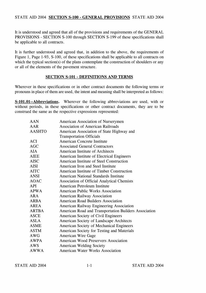
SECTION S-100 - GENERAL PROVISIONS
It is understood and agreed that all of the provisions and requirements of the GENERALPROVISIONS - SECTION S-100 through SECTION S-199 of these specifications shallbe applicable to all contracts.
It is further understood and agreed that, in addition to the above, the requirements ofFigure 1, Page 1-93, S-100, of these specifications shall be applicable to all contracts onwhich the typical section(s) of the plans contemplate the construction of shoulders or anyor all of the elements of the pavement structure.
SECTION S-101 - DEFINITIONS AND TERMS
Wherever in these specifications or in other contract documents the following terms orpronouns in place of them are used, the intent and meaning shall be interpreted as follows:
S-101.01--Abbreviations. Wherever the following abbreviations are used, with orwithout periods, in these specifications or other contract documents, they are to beconstrued the same as the respective expressions represented:
AAN American Association of NurserymenAAR Association of American RailroadsAASHTO American Association of State Highway and
Transportation Officials ACI American Concrete InstituteAGC Associated General ContractorsAIA American Institute of ArchitectsAIEE American Institute of Electrical EngineersAISC American Institute of Steel ConstructionAISI American Iron and Steel InstituteAITC American Institute of Timber ConstructionANSI American National Standards InstituteAOAC Association of Official Analytical ChemistsAPI American Petroleum InstituteAPWA American Public Works AssociationARA American Railway AssociationARBA American Road Builders AssociationAREA American Railway Engineering AssociationARTBA American Road and Transportation Builders AssociationASCE American Society of Civil EngineersASLA American Society of Landscape ArchitectsASME American Society of Mechanical EngineersASTM American Society for Testing and MaterialsAWG American Wire GageAWPA American Wood Preservers AssociationAWS American Welding SocietyAWWA American Water Works Association
STATE AID 2004 STATE AID 2004
STATE AID 2004 STATE AID 20041-2
SECTION S-101 SECTION S-101
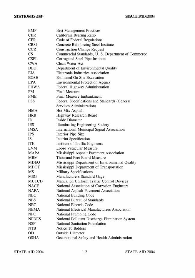
BMP Best Management PracticesCBR California Bearing RatioCFR Code of Federal RegulationsCRSI Concrete Reinforcing Steel InstituteCCR Construction Change RequestCS Commercial Standards, U. S. Department of CommerceCSPI Corrugated Steel Pipe InstituteCWA Clean Water ActDEQ Department of Environmental QualityEIA Electronic Industries AssociationEOSE Estimated On Site ExcavationEPA Environmental Protection AgencyFHWA Federal Highway AdministrationFM Final MeasureFME Final Measure EmbankmentFSS Federal Specifications and Standards (General
Services Administration)HMA Hot Mix AsphaltHRB Highway Research BoardID Inside DiameterIES Illuminating Engineering SocietyIMSA International Municipal Signal AssociationIPS Interior Pipe SizeIS Interim SpecificationITE Institute of Traffic EngineersLVM Loose Vehicular MeasureMAPA Mississippi Asphalt Pavement AssociationMBM Thousand Feet Board MeasureMDEQ Mississippi Department of Environmental QualityMDOT Mississippi Department of TransportationMS Military SpecificationsMSG Manufacturers Standard GageMUTCD Manual on Uniform Traffic Control DevicesNACE National Association of Corrosion EngineersNAPA National Asphalt Pavement AssociationNBC National Building CodeNBS National Bureau of StandardsNEC National Electric CodeNEMA National Electrical Manufacturers AssociationNPC National Plumbing CodeNPDES National Pollutant Discharge Elimination SystemNSF National Sanitation FoundationNTB Notice To BiddersOD Outside DiameterOSHA Occupational Safety and Health Administration
STATE AID 2004 STATE AID 2004
STATE AID 2004 STATE AID 20041-3
SECTION S-101 SECTION S-101
PCI Prestressed Concrete InstitutePM Plan MeasureRAP Recycled Asphalt PavementRCRA Resource Conservation and Recovery ActSA Supplemental AgreementSAE Society of Automotive EngineersSOP The Office of State Aid Road Construction
Standard Operating ProceduresSP Special ProvisionsSS Supplemental SpecificationsSSPC Steel Structures Painting CouncilSWPPP Storm Water Pollution Prevention PlanTRB Transportation Research BoardTSR Tensile Strength RatioUL Underwriters Laboratories, Inc.UNC Upset National Coarse Threaded BoltsUST Underground Storage Tank
S-101.02--Definitions.
Additive - A substance or agent added in small amounts to a basic ingredient of a mixtureprior to mixing.
Admixture - A substance or agent added in small amounts to the basic ingredients of amixture during the mixing process.
Advertisement - The public announcement, as required by law, inviting bids for work tobe performed or materials to be furnished.
Alternate Designs - Alternate design of construction or of construction and materialsdesignated in the bid schedule of the proposal as Alternate Designs which must bepre-selected by the Contractor and indicated on his bid. Alternate Designs may containAlternate or Optional Items.
Alternate Items - Alternate pay items of work, or materials and work designated in the bidschedule of the proposal as Alternate Items, with separate pay item numbers, and whichmust be preselected by the Contractor and indicated on his bid.
Award - The acceptance by the Board of Supervisors of a bid.
Base Course - The layer or layers of specified or selected material of designed thicknessplaced on a subbase or a subgrade to support a pavement.
STATE AID 2004 STATE AID 2004
STATE AID 2004 STATE AID 20041-4
SECTION S-101 SECTION S-101
Basement Soils - That portion of the roadway in embankment areas below the design soiland to the bottom of the embankment or undercut, whichever is lower, and that portionof the earthwork in cut areas below the design soil and to the bottom of any undercut orother treatment required, whichever is lower.
Bidder - An individual, firm, partnership or corporation formally submitting a bid for theadvertised work.
Binder Course - A combination of graded aggregate and bituminous material whichconstitutes the lower layer or layers of a flexible pavement, but not part of bituminousbase or subbase course.
Board - The legally elected Board of Supervisors of the County who are responsible forthe project and are shown as the party of the first part to the contract.
Borrow - Suitable material from approved sources outside the roadway prism, usedprimarily for embankments.
Box Bridge - A box culvert having a clear distance between inside face of the end supportsexceeding 20 feet measured along the centerline of the roadway.
Bridge - A structure, including supports, erected over a depression or an obstruction, aswater, highway, or railway, and having a track or passageway for carrying traffic or othermoving loads and having a length measured along the center of the roadway of more than20 feet between undercopings of abutments or extreme ends of openings for multipleboxes.
Bridge Length - The length of a bridge structure is the overall length measured along theline of survey stationing back to back of backwalls of abutments, if present, otherwise endto end of the bridge floor; but in no case less than the total clear opening of the structure.
Bridge Roadway Width - The clear width measured at right angles to the longitudinalcenterline of the bridge between the bottom of curbs or railing.
Bridge Site - Unless otherwise specified in the contract, the bridge site shall be the entirearea between the right-of-way lines and between lines paralleling the bridge ends andpassing through the longitudinal extremities of the substructure or superstructure,whichever is greater.
Calendar Day - Any day shown on the calendar, beginning and ending at midnight.
Catastrophic Event - Slides, flooded major streams when such flood is determined to bein excess of the design stage; earthquakes, tornadoes, hurricanes, and other suchdisastrous phenomena of nature.
Commission - The Mississippi Transportation Commission.
STATE AID 2004 STATE AID 2004
STATE AID 2004 STATE AID 20041-5
SECTION S-101 SECTION S-101
Conformity - The degree of perfection required for the materials furnished and the workperformed, and determined:
(a) In the case of a "specified" value of a measurable characteristic, as setout in S-700.04.
(b) In the case of a required "minimum" or "maximum" value of ameasurable characteristic, as set out in S-700.04.
(c) In the case of a required non-measurable characteristic, as beingsatisfactory to the Engineer.
Construction Change Request - An approved written order covering changes in the plansor quantities or both, within the scope of the contract, and establishing the basis ofpayment and time adjustments for the work affected by the changes.
Contract - The written agreement between the County Board of Supervisors, theContractor and the State Aid Engineer setting forth the obligations of the partiesthereunder, including but not limited to, the performance of the work, the furnishing oflabor and materials, and the basis of payment.
The contract includes the invitation for bids, proposal, contract form and contract bond,specifications, supplemental specifications, general and detailed plans, special provisions,notices to bidders, and also any construction change requests and agreements that arerequired to complete the construction of the work in an acceptable manner, includingauthorized extensions thereof, all of which constitute one instrument.
Contract Bond - The approved form of security, executed by the Contractor and hisSurety, guaranteeing complete execution of the contract and all supplemental agreementspertaining thereto and the payment of all legal debts pertaining to the construction of theproject.
Contract Documents - All original or official papers relied upon as the basis, proof orsupport of the contract and shall include papers stated in the definition of the Contract.
Contract Time - The period of time, including authorized extensions, allowed forcompletion of the work under the contract.
Contract Unit Price - The price established in S-902-Proposal, or by SupplementalAgreement for a specifically described unit of work.
Contractor - The individual, firm, partnership or corporation contracting with the CountyBoard of Supervisors for performance of prescribed work.
Controlling Work - The work or construction operations normally expected to be inprogress as determined by the Engineer.
STATE AID 2004 STATE AID 2004
STATE AID 2004 STATE AID 20041-6
SECTION S-101 SECTION S-101
County - The county in which the work specified is to be performed.
Cross Slope - The rate of transverse slope in a roadbed element.
Culvert - Any structure not classified as a bridge which provides an opening under theroadway.
Department - The Mississippi Department of Transportation.
Design Grade - Design grade is any intermediate control grade at a vertical distance, asestablished on the typical section of the plans for the various intermediate courses, belowprofile grade.
Design Soil - That portion of the roadbed consisting of the top three feet of untreated ortreated soils in excavated sections and embankments.
Detour - A designated existing route around a construction site.
Director - The Executive Director of the Mississippi Department of Transportation actingdirectly or through his authorized representatives.
Diversion - Temporary rerouting of traffic on a construction site.
Documentation - Written evidence recorded by an authorized individual of facts orconditions relating to a particular contractual matter.
Elements of Geometric Design - Those geometric elements of the highway which aredefined in the "AASHTO Policy on Geometric Design" in effect at the time bids arereceived.
Engineer - The County/LSBP Engineer for each respective County, acting directly orthrough his duly authorized representatives, who is responsible for engineeringsupervision of the construction.
Equipment - All machinery and equipment, together with the necessary supplies forupkeep and maintenance, and also tools and apparatus necessary for the properconstruction and acceptable completion of the work.
Executive Director - The Executive Director of the Mississippi Department ofTransportation acting directly or through his authorized representatives.
Extra Work - An item of work not provided for in the contract as awarded, or an item ofwork provided for in the contract the nature or character of which is changed such as tojustify a price adjustment, either of which is found essential in the satisfactory completionof the contract within its intended scope.
1-7
SECTION S-101 SECTION S-101
Extra Work Order - A CCR/SA concerning the performance of work or furnishing ofmaterials involving extra work. Such extra work may be performed at contract pricesor on a force account basis as provided elsewhere in these specifications.
Fixed Contract Unit Price - When the bid schedule of the proposal form indicates a fixedcontract unit price (FCP), this price shall become the contract price for that item and shallbe used in determining the total amount of the proposal.
Foreign Materials - Foreign materials are defined as being any material or manufacturedproduct whose manufacturing process takes place outside the United States.
Hazardous Waste - Wastes that are regulated or “listed” under RCRA (40 CFR 261), orare ignitable, corrosive, reactive or toxic.
Highway, Street, or Road - A general term denoting a public way for purposes ofvehicular travel, including the entire area within the right-of-way.
Holidays, Legal - In the State of Mississippi, holidays occur on:
January l New Year's DayThird Monday in January Robert E. Lee's and
Dr. Martin Luther King, Jr.'sBirthday
Third Monday in February Washington's BirthdayLast Monday in April Confederate Memorial DayLast Monday in May National Memorial Day and
Jefferson Davis' BirthdayJuly 4 Independence DayFirst Monday in September Labor DayNovember 11 Armistice (Veterans') DayThanksgiving Day As ProclaimedDecember 25 Christmas Day
When a legal holiday falls on a Saturday or Sunday, the following Monday will beobserved as a legal holiday.
Inspector - The Engineer's authorized representative assigned to make detailed inspectionsof contract performance.
STATE AID 2004 STATE AID 2004
STATE AID 2004 STATE AID 20041-8
SECTION S-101 SECTION S-101
Invitation for Bids - The advertisement for proposals for all work or materials on whichbids are required. The advertisement will indicate with reasonable accuracy the quantityand location of the work to be done or the character and quantity of the material to befurnished and the time and place of the opening of proposals.
Laboratory - The testing laboratory of the Department or other approved testinglaboratory which may be designated by the Engineer.
Legend - The words, letters and arrows, and other symbols shown on the plans anddesignated as legend, required to be placed on the surface of a pavement in the form ofpaint and glass beads, thermoplastic and glass beads or other similar specified materials,to serve as pavement markings.
Local Traffic - Traffic whose origin or destination is adjacent to that part of the projectunder construction.
Major and Minor Contract Items - A major item of work shall be defined as an itemwhose total monetary value, determined by multiplying the proposal quantity by thecontract unit price, is equal to or greater than five percent of the original total contractamount. Unless otherwise specifically shown in the contract, all other items shall beconsidered minor items. Minor items shall become major items when increased to theextent that the total monetary value of such item at the original contract unit price is equalto or greater than five percent of the original total contract amount. A major item of workwill remain a major item of work unless it is completely eliminated, or reduced bySupplemental Agreement for the purpose of substituting another item(s) in lieu thereof.When an item is eliminated, it shall be treated as provided for under S-109.05.
Materials - Any substances specified for use in the construction of the project and itsappurtenances.
Notice to Bidders - All notices, issued to the prospective bidders, pertaining to orestablishing requirements governing the submission of proposals, quantities or qualitiesof materials or work, the performance of the work, or payment therefor.
Notice to Contractors - Pre-bidding notices to prospective bidders, including theadvertisement and other pertinent pre-bid information labeled as Notice to Contractors.
Notice to Proceed - Written notice to the Contractor to proceed with the contract workincluding, when applicable, the date of beginning of contract time.
STATE AID 2004 STATE AID 2004
STATE AID 2004 STATE AID 20041-9
SECTION S-101 SECTION S-101
Omitted Section - A section within the designated project limits in which no work(excluding construction signing, approaches and/or temporary connections) is to beperformed, and the Contractor does not have any responsibility for maintenance of theroadway or traffic unless specifically provided of in the contract.
Optional Items - Items listed in the bid schedule of the proposal which are considered tobe comparable for the purpose intended and from which the Contractor is not required tomake a selection prior to or at the time of execution of the contract.
Pavement - The portion of the roadbed constructed upon the base course and specificallyconstructed as the contact element for vehicular traffic.
Pavement Structure - The combination of a pavement, a base course and, when specified,a subbase course, placed on a subgrade to support the traffic load and distribute it to theroadbed.
Pay Item - A specifically described unit of work for which a price is provided in thecontract.
Plans - The approved plans, profiles, typical cross-sections, working drawings andsupplemental drawings, or exact reproduction thereof, which show the location, character,dimensions, and details of the work to be done.
Profile Grade - The trace of a vertical plane intersecting the top surface of the proposedwearing surface as shown on the plans or established by the Engineer, usually along thelongitudinal centerline of the roadbed. Profile grade means either elevation or gradientof such trace according to the context.
Project - The specific section of the highway together with the appurtenances andconstruction to be performed thereon under the contract.
Proposal - The offer of a bidder, on the prescribed form, to perform the work at theprices quoted.
Proposal Form - The approved form on which the Office of State Aid Road Constructionrequires bids to be prepared and submitted for the work.
Proposal Guaranty - The certified check, cashier's check or bid bond furnished with thebid to guarantee that the bidder will enter into a contract for the work and furnishacceptable bond if his bid is accepted.
STATE AID 2004 STATE AID 2004
STATE AID 2004 STATE AID 20041-10
SECTION S-101 SECTION S-101
Qualified prison facility -Aany prison facility in which convicts, during the 12 monthperiod ending July 1, 1987, produced materials for use in Federal Aid highwayconstruction projects.
Retainage - A general term denoting funds withheld from partial payments.
Right-of-Way - A general term denoting land, property, or interest therein, usually in astrip, acquired for or devoted to a highway and its appurtenances.
Roadbed - The graded portion of a highway within top and side slopes prepared as afoundation for pavement structure and shoulders.
Roadside - A general term denoting the area adjoining the outer edge of a roadway.
Roadside Development - Those items necessary to the complete highway which providefor the preservation of landscape materials and features; the rehabilitation and protectionagainst erosion of all areas disturbed by construction through seeding, sodding, mulchingand the placing of other ground covers; and such suitable planting, other improvementsand public facilities as may increase the effectiveness and usefulness and enhance theappearance of the highway.
Roadway - All surface portions of the highway between shoulder lines. Divided highwaysare considered to have two roadways.
Roadway Structure - All vertical and horizontal elements of the work, exclusive ofbridges, designed to provide and support the roadway.
Shoulders - The portion of the roadway contiguous with the traveled way for the lateralsupport of the other elements of the pavement structure, and for emergency use of stoppedvehicles.
Sidewalk - That portion of the road, highway, or street primarily constructed for use bypedestrians.
Special Provisions - Additions and revisions to the standard and supplementalspecifications covering conditions peculiar to an individual project, and included in theproposal assemblies.
Specifications - A general term applied to all directions, provisions and requirementspertaining to performance of the work or materials to be used.

STATE AID 2004 STATE AID 2004
STATE AID 2004 STATE AID 20041-11
SECTION S-101 SECTION S-101
Standard Operating Procedures - The Office of State Aid Road Construction StandardOperating Procedures are the rules, regulations, instructions and policies, promulgated bythe State Aid Engineer acting through his authorized representatives, which are requiredto effectively accomplish the statutory responsibilities of the Office of State Aid RoadConstruction and which are compiled in volumes, distributed to all County/LSBPEngineers, and on file at the office of the State Aid Engineer.
State - The State of Mississippi acting through its authorized representative.
State Aid Engineer - The State Aid Engineer, appointed by the Governor of the State ofMississippi acting directly or through a duly authorized representative.
Structures - Bridges, culverts, catch basins, drop inlets, retaining walls, cribbing,manholes, endwalls, buildings, sewers, service pipes, underdrains, foundation drains, andsimilar features which may be required in the work.
Subbase Course - The layer(s) in the pavement structure between the design soil and thebase course. Treated portions of the design soil may be considered as subbase or aportion thereof when its treatment or stabilization is sufficient to adequately improve thebearing value.
Subcontractor - An individual, firm, partnership or corporation to whom the Contractor,with the written consent of the Board and the State Aid Engineer, sublets part of thecontract.
Subgrade - The top surface of a design soil upon which the pavement structure andshoulders are constructed.
Substructure - Those parts of a bridge below the bearings of simple and continuous spans,below the bottom surface of concrete box girder spans in which the piers form an integralpart of the span-pier entity, or below wingwalls of abutments.
Superintendent - The Contractor's authorized representative in responsible charge of thework.
Superstructure - All parts of a bridge above and exclusive of the substructure.
Supplemental Agreement - A written agreement by the parties of the contract coveringalterations or extra work necessary for the completion of the contract.
Supplemental Specification - Additions and revisions to the Standard Specifications thatare adopted subsequent to issuance of the printed book.
STATE AID 2004 STATE AID 2004
STATE AID 2004 STATE AID 20041-12
SECTION S-101 SECTION S-101
Surety - The corporate body, qualified under the laws of Mississippi, which is bound withand for the successful bidder by the "bid bond" to execute a satisfactory contract with andfor the Contractor for the acceptable performance of the contract and for his payment ofall legal taxes and debts pertaining to the construction of the project, including paymentof State Sales Tax as prescribed by law.
Temporary Structures - Structures required to maintain traffic while the Contractorconstructs structures. The temporary structure shall include the earth approaches theretounless otherwise specified.
The Work - The furnishing of all labor, materials, equipment, and incidentals necessaryto the successful completion of the project and the carrying out of the duties andobligations imposed by the contract.
Titles (or Headings) - The titles or headings of the sections and subsections herein areintended for convenience of reference and shall not be considered as having any bearingon their interpretation.
Township, Town, City or District - A subdivision of the County used to designate oridentify the location of the proposed work.
Traveled Way - A portion of the roadway improved, designed or ordinarily used forvehicular travel, exclusive of shoulders or berms.
Work Order - A written order, signed by the Engineer, of a contractual status requiringperformance by the Contractor without negotiation of any sort.
Working Day - A calendar day, exclusive of the days listed below, on which weather andsoil conditions are such that the Contractor can proceed with construction for seven (7)consecutive daylight hours with normal working forces engaged in performing thecontrolling work which would be in progress at that time. Excluded days are:
1. Saturdays2. Sundays3. State recognized legal holidays4. Days on which delays are attributable to: (a) The County or State (b) Governmental Authorities (c) Catastrophic events (d) Awaiting growth and coverage of planted vegetation,
waiting for prime or concrete to cure, or otherspecific conditions set out elsewhere in the contract
STATE AID 2004 STATE AID 2004
STATE AID 2004 STATE AID 20041-13
SECTION S-101 SECTION S-101
State recognized legal holidays are as set out in this Subsection. When a legal holidayfalls on a Saturday or Sunday, the following Monday will be observed as a legal holiday.
The controlling work will be determined after careful consideration of the Contractor'soperation(s) of construction that normally should be in progress at that time, as essentialto the orderly completion of the work within the time allowed.
The acceptance of any progress payment accompanying any estimate, without writtenprotest, shall be acknowledgment by the Contractor that the number of working daysshown on the estimate are correct. The number of working days shall be indicated in theproposal and counted from the designated date for beginning work or date work actuallybegan, whichever occurs first, to the date of final acceptance.
Working Drawings - Stress sheets, shop drawings, erection plans, falsework plans,framework plans, cofferdam plans, bending diagrams for reinforcing steel, or any othersupplementary plans or similar data which the Contractor is required to submit to theEngineer for approval.
S-101.03. Whenever in these specifications terms not defined herein are used to identifygeometric elements of the work, such terms shall be understood to have the meaning asestablished by AASHTO, and current at the time bids are received.
S-101.04--Presumption. To avoid repetition of expressions, it is provided that anydirective, action or opinion that is not so denoted shall be understood to be followed bythe words "by the Engineer" or "to the Engineer."
STATE AID 2004 STATE AID 2004
STATE AID 2004 STATE AID 20041-14
SECTION S-102 - BIDDING REQUIREMENTS AND CONDITIONS
S-102.00--Advertisement. In conformity with State law, the Board will publish a Noticeto Contractors giving notice of a request for bids. This notice will become one of thecontract documents if award is made.
The advertisement will state the time and place for submission of sealed proposals; thelocation and description of the proposed work; estimates of the quantities and kinds ofwork to be performed or materials to be furnished and a schedule of pay items for whichunit bid prices are asked; specified contract time; and instructions to bidders regardingproposal forms, basis of award, proposal guaranty required, plans, specifications, laborrequirements, supplemental specifications and/or special provisions, and other pertinentinformation. Proof of publication of advertisement shall be available at the time ofopening of bids.
S-102.01--Prequalification of Bidders. Information may be required from time to timefrom prospective bidders before issuing proposals.
The attention of prospective bidders is directed to all fees and taxes required for theprivilege of doing business within the State.
As a condition precedent to the opening of a bid financed wholly with State funds andwhich is equal to or in excess of 50,000 dollars, the bidder must have a Certificate ofResponsibility issued by the Mississippi State Board of Contractors and the certificatenumber must be shown on the outside of the sealed envelope containing the bidproposal. When a bid is less than 50,000 dollars, a Certificate of Responsibility is notrequired but either the statement, "Bid less than 50,000 dollars" or a certificate numbermust be shown on the envelope.
In addition, prospective bidders are reminded of the requirements set forth by theMississippi State Board of Public Contractors that the classification of a contractor, asregistered with the Board, must be the same as the nature of the proposed work on whichthe bid will be submitted.
When two or more persons, firms, partnerships or corporations are submitting a jointproposal, each of the persons, firms, partnerships or corporations may be required tocomply with the above prequalification requirements.
S-102.02--Contents of Proposal Forms. The proposal forms will state the location anddescription of the contemplated construction, will show estimates of the quantities andkinds of work to be performed or materials to be furnished, and will have a schedule ofitems for which unit bid prices are invited.

STATE AID 2004 STATE AID 2004
STATE AID 2004 STATE AID 20041-15
SECTION S-102 SECTION S-102
The proposal form will state the time in which the work must be completed, the amountof the proposal guaranty, and the date, time and place of the opening of proposals. Theform will also include supplemental specifications and/or special provisions andrequirements which vary from or are not contained in the Standard Specifications.
All papers bound with, attached to, or designated for addition or substitution in theproposal form are considered a part thereof and must not be detached or altered when theproposal is submitted.
The plans, specifications and other documents designated in the proposal form shall beconsidered a part of the proposal as if attached to and included in the proposal form.
Plans and specifications for any project(s) identified in an Advertisement will be on filein the offices of the County Engineer.
Prospective bidders will obtain proposals and plans from the County Engineer. Cost andother general information concerning the proposal and plans will be as contained in theNotice to Contractors published by the Board.
S-102.03--Issuance of Proposal Form. The Board reserves the right to refuse to furnisha prospective bidder with a proposal form for any of the following reasons:
(a) Lack of competency and adequate machinery, plant,or other equipment, as revealed by the informationobtained as provided in S-102.01 or otherdeterminations made by the Board.
(b) Uncompleted work which, in the judgment of theBoard and State Aid Engineer, might hinder orprevent the prompt completion of additional work ifawarded.
(c) Failure to pay, or satisfactorily settle, all bills due forlabor and materials on former contracts in force at thetime of issuance of proposals.
(d) Unsatisfactory performance on previous contracts.
(e) Failure to promptly reimburse the Board for anyoverpayment that might have occurred.

STATE AID 2004 STATE AID 2004
STATE AID 2004 STATE AID 20041-16
SECTION S-102 SECTION S-102
(f) Actions in bidding or subcontracting which have theeffect of limiting competition and violating thecompetitive bid process; or if any partner, associationmember, corporate official or individual owner,respectively, has been convicted or entered a plea ofguilty or nolo contendere in any legal jurisdiction ofthe United States or any of the various states offederal or state crimes that involve the restraint oftrade or limiting competition in any manner, or hasbeen debarred from bidding on public contracts by theState of Mississippi or any of its agencies; or by oneor more of the other States or any of their agencies;or by a federal agency.
S-102.04--Interpretation of Quantities in Bid Schedule. The quantities appearing in thebid schedule are approximate only and are prepared for the comparison of bids. Paymentto the Contractor will be made only for the actual quantities of work performed andaccepted or materials furnished and accepted in accordance with the contract. Thescheduled quantities of work to be done and materials to be furnished may each beincreased, decreased, or omitted as hereinafter provided.
S-102.05--Examination of Plans, Specifications, Special Provisions, Notices to Biddersand Site of Work. It is the intent that the Engineer will prepare full, complete, andaccurate plans and specifications giving directions that will enable any competentContractor to carry them out. The bidder is expected to examine carefully the site of theproposed work, the proposal, plans, specifications, supplemental specifications and/orspecial provisions, notices to bidders and contract forms before submitting a proposal.The submission of a bid shall be considered prima facie evidence that the bidder has madesuch an examination and is satisfied as to the conditions to be encountered in performingthe work and as to the requirements of the plans, specifications, supplementalspecifications, notices to bidders, special provisions, contract, and the Federal, State,and local laws which will in any way affect his execution of the work.
Boring logs and other records of subsurface investigations may be available for inspectionby bidders. It is understood that such information was obtained and is intended for designand estimating purposes only. It is made available to bidders so that they will have accessto identical subsurface information available to the Board and Office of State Aid RoadConstruction and is not intended as a substitute for personal investigation, interpretationsand judgment of the bidders.
Bidders may inspect records of the Engineer and Office of State Aid Road Constructionas to investigations made, subject to the conditions hereinbefore set forth.
STATE AID 2004 STATE AID 2004
STATE AID 2004 STATE AID 20041-17
SECTION S-102 SECTION S-102
S-102.06--Preparation of Proposal. The bidder shall submit his proposal on the formsfurnished by the Office of State Aid Road Construction and shall enter in figures a unitprice and extension in the appropriate columns for each bid item exclusive of those itemsfor which a fixed contract unit price and the extension are shown. The bidder shall alsoenter where indicated the subtotal amount for each of the various divisions and the totalamount of the proposal which shall also include the extensions of the items with a fixedcontract unit price. In case of discrepancy between a unit price and the extension, the unitprice will govern; and the extension and the total amount of the proposal will becorrected. All the figures shall be in ink or typed.
When the bid schedule contains a fixed contract unit price (FCP) for an item, this priceshall be the contract unit price for the item and no alteration shall be made by the bidder.
When an item in the proposal contains a choice to be made by the bidder, the bidder shallindicate his choice in accordance with the instruction to bidders in Section S-902 -Proposal (reference is made to Alternate Designs, Alternate Items, and Optional Items inS-101.02).
Where the bid schedule lists alternate designs or alternate items, one alternate that is bidshall be designated by drawing a line or lines through other listed alternate(s) as provided,and thereafter no further choice will be permitted.
When the bid schedule lists optional items, the Contractor may, but is not required to,make his selection at the time of bidding or prior to or at the time of execution of thecontract. It shall be the Contractor's responsibility to provide notice of selection to theCounty Engineer and the State Aid Engineer sufficiently in advance to provide areasonable time for the exchange of the documentation for selection prior to ordering ma-terials or performing work on any optional item.
Each proposal issued to prospective bidders will contain, in duplicate, blank affidavitforms to be executed, and sworn to, by the bidder, before a person who is authorized bythe laws of any State to administer oaths, and returned with the bidder's proposal.
This "Non-Collusion Affidavit" shall be a sworn statement, filed in duplicate, executedby, or on behalf of, the individual, firm or corporation to whom the contract is to beawarded (if the successful bidder), certifying that such individual, firm, or corporation hasnot, directly or indirectly, entered into any agreement, participated in any collusion, orotherwise taken any action in restraint of free competitive bidding in connection with suchcontract nor have any of its officers, partners, employees, or principal owners; and thatsuch individual, firm or corporation nor any of its directors, officers, partners, principalowners or managerial employees are debarred from bidding on public contracts by theState of Mississippi or any of its agencies; or by one or more of the other States or anyof their agencies; or by a federal agency.
Failure on the part of the bidder to execute the affidavit will result in his proposal beingdeclared incomplete and rejected.
STATE AID 2004 STATE AID 2004
STATE AID 2004 STATE AID 20041-18
SECTION S-102 SECTION S-102
The bidder's proposal must be signed in ink by the individual, by one or more membersof the partnership, by one or more members or officers of each firm representing a jointventure, or by one or more officers of a corporation, or by an agent of the Contractorlegally qualified and acceptable to the State. If the proposal is made by an individual, hisname and post office address must be shown; by a partnership, the name and post officeaddress of each partnership member must be shown; as a joint venture, the name and postoffice address of each member or officer of the firms represented by the joint venturemust be shown; by a corporation, the name of the corporation and the business addressof its corporate officials must be shown.
The address stated by the bidder on his proposal shall be his permanent address, unlesschanged by him by written notice to the Board and the State Aid Engineer, and all noticesto the Contractor provided for in the contract shall be considered as given or delivered tothe Contractor when mailed or delivered to that address by the Engineer or Office of StateAid Road Construction.
S-102.07--Irregular Proposals. Proposals will be considered irregular and may berejected for any of the following reasons:
(a) If the proposal is on a form other than that securedfrom the Engineer, or if the form is altered or anypart thereof is detached.
(b) If there are unauthorized additions, conditional oralternate bids, or irregularities of any kind which maytend to make the proposal incomplete, indefinite, orambiguous as to its meaning.
(c) If the bidder adds any provisions reserving the rightto accept or reject an award, or to enter into acontract pursuant to an award.
(d) If the proposal does not contain a unit price for eachpay item listed except in the case of alternate oroptional pay items.
(e) If the proposal, Section S-902, does not containacknowledgment of receipt and addition to theproposal and contract documents of all addenda issuedprior to opening of bids.
(f) Failure to execute required affidavits, certificates,etc., and furnish proposal guaranty.
STATE AID 2004 STATE AID 2004
STATE AID 2004 STATE AID 20041-19
SECTION S-102 SECTION S-102
S-102.08--Proposal Guaranty. Proposals will not be considered unless accompanied bycertified check, cashier's check or bid bond, made payable to the County and the State ofMississippi, in an amount of not less than five percent of the total amount of the proposaloffered, as evidence of good faith and as a guaranty that if awarded the contract, thebidder will execute the contract and give contract bond as required by law and stipulatedin S-103.05.
If a bid bond is offered as guaranty, the bond must be on a form approved by the StateAid Engineer, made by a Surety, and must be acceptable to the Board and the State AidEngineer and signed or countersigned by a qualified Mississippi resident agent and thebidder.
S-102.09--Delivery of Proposal. Unless otherwise specified, each proposal must besubmitted sealed in a plain envelope with the following listed information plainly writtenon the outside or face of the envelope:
(1) Addressee: Board of Supervisors of County.
(2) Bid of: Name of Person or Firm submitting the bid.
(3) Permanent address of the Bidder: Post Office Box Number, or StreetAddress, and the City and State of the Bidder.
(4) For: Project Number County of .
(5) Date of Submission of Bid.
(6) Bidders Certificate of Responsibility Number issued by the MississippiState Board of Public Contractors.
Proposal forms when issued, by the Engineer, are not transferable and no name or namesof interested parties may be added other than those to whom the proposal was issued.
The County Engineer will keep a list of the bidders to whom proposals have been issuedand bids will be accepted only under the name of the bidders issued proposals.
No proposal will be accepted or considered which has not been received at the office ofthe Board prior to the time specified in the Notice to Contractors.
S-102.10--Withdrawal or Revision of Proposals. A bidder may withdraw or revise aproposal after it has been deposited with the Board, provided the request for suchwithdrawal or revision is received by the Board, by facsimile, in writing or by telegram,before the time set for opening proposals.
STATE AID 2004 STATE AID 2004
STATE AID 2004 STATE AID 20041-20
SECTION S-102 SECTION S-102
S-102.11--Combination or Conditional Proposals. If the Board and State Aid Engineerso elects, proposals may be issued for projects in combination or separately, so that bidsmay be submitted either on the combination or on separate units of the combination. TheBoard and State Aid Engineer reserves the right to make awards on combination bids orseparate bids to the best advantage of the Board. No combination bids, other than thosespecifically set up in the proposals by the Board and State Aid Engineer, will beconsidered. At the discretion of the Board and State Aid Engineer, separate contracts maybe written for each individual project included in the combination.
Conditional proposals will be considered when so stated in the special provisions.
S-102.12--Public Opening of Proposals. Proposals will be opened and read publicly atthe time and place indicated in the proposal. Bidders, their authorized agents, and otherinterested parties are invited to be present.
S-102.13--Disqualification of Bidders. Either of the following reasons may beconsidered as being sufficient for the disqualification of a bidder and the rejection of hisproposal or proposals:
(a) More than one proposal for the same work from anindividual, firm, or corporation under the same ordifferent names.
(b) Evidence of collusion among bidders. Participants insuch collusion will receive no recognition as biddersfor any future work in any County until any suchparticipant shall have been reinstated as a qualifiedbidder.
S-102.14--Material Guaranty. At the option of the Board or State Aid Engineer, thesuccessful bidder shall be required at any time before or after the award or execution ofthe contract to furnish a complete statement of the origin, composition, and manufactureof any and all materials to be used in the construction of the work, and shall provide theCounty and State with access to all sources of materials for sampling and testing todetermine their quality, uniformity, and fitness for the work in accordance with thecontract.
STATE AID 2004 STATE AID 2004
STATE AID 2004 STATE AID 20041-21
SECTION S-103 - AWARD AND EXECUTION OF CONTRACT
S-103.01--Consideration of Proposals. After the proposals are opened and read, theywill be compared on the basis of the summation of the products of the approximatequantities shown in the bid schedule by the unit prices bid. The results of comparisonswill be immediately available to the public. In the event of a discrepancy between unitprices and extensions, the unit price shall govern.
In consideration of contract proposals which are equal to or in excess of 50,000 dollarsand financed wholly with State funds, preference will be given to resident Contractors,and a nonresident bidder domiciled in a state having laws granting preference to localContractors will be considered for such contracts on the same basis as the nonresidentbidder’s State awards contracts to Mississippi Contractors bidding under similarcircumstances.
When a nonresident Contractor submits a bid equal to or in excess of 50,000 dollars andthe contract is financed wholly with State funds, the Contractor shall attach thereto a copyof the current laws from the State of domicile and an explanation thereof pertaining totreatment of nonresident Contractors. If no preferential treatment is provided for residentContractors in the State of domicile and contracts are awarded to the lowest responsiblebidder, a statement to this effect shall be attached. Should the attachment not accompanythe bid when submitted, the Contractor shall have 10 days following the opening of bidsto furnish the information to the Engineer.
As used herein, the term “resident Contractors” includes a nonresident person, firm, orcorporation that has been qualified to do business in this State and has maintained apermanent full-time office in the State of Mississippi for two years prior to January 1,1986, and the subsidiaries and affiliates of such a person, firm or corporation.
The right is reserved to reject any or all proposals, to waive technicalities, or to advertisefor new proposals, if in the judgment of the awarding authority the best interests of theCounty will be promoted thereby.
S-103.02--Award of Contract. The award of contract, if awarded, will be made within60 calendar days after the opening of proposals to the qualified bidder whose proposalcomplies with all the requirements prescribed. The award of contracts involving theexpenditure of Federal funds will be contingent upon approval of the State Aid Engineerand the Executive Director of the Mississippi Department of Transportation. Thesuccessful bidder will be notified, by letter mailed to the address shown on his proposal,that his bid has been accepted and that he has been awarded the contract.
Resident Contractors actually domiciled in Mississippi which may be corporate,individuals or partnerships are to be granted preference over nonresidents in awarding ofcontracts in the same manner and to the same extent as provided by the laws of the Stateof domicile of the nonresident.
STATE AID 2004 STATE AID 2004
STATE AID 2004 STATE AID 20041-22
SECTION S-103 SECTION S-103
S-103.03--Cancellation of Award. The Board and the State Aid Engineer reserve theright to cancel the award of any contract at any time before the execution by all partieswithout liability against either party.
S-103.04--Return of Proposal Guaranty. Bid bonds will not be returned.
Certified checks or cashier's checks submitted as proposal guaranties, except those of thetwo lowest bidders, will be returned immediately following the opening and checking ofthe proposals. The retained proposal guaranty of the unsuccessful of the two lowestbidders will be returned within ten days following the award of contract, and that of thesuccessful bidder will be returned after a satisfactory contract bond has been furnished andthe contract has been executed.
In the event no award is made within 15 days after the opening of bids, the Board andState Aid Engineer may permit the successful bidder to substitute a satisfactory bidder'sbond as a guaranty in lieu of certified check or cashier's check submitted with hisproposal.
Should no award be made within 60 calendar days, all proposals will be rejected and allproposal guaranties returned, unless the lowest responsible bidder, at the request of theBoard and State Aid Engineer agrees in writing to a longer delay.
S-103.05--Requirement of Contract Bond. Prior to the execution of the contract, thesuccessful bidder shall execute and deliver to the Board a contract bond or bonds in a sumequal to the full amount of the contract. In the event of award of a joint bid, eachindividual, firm, or corporation shall assume jointly the full obligations under the contractand contract bond. The form of the bond or bonds shall be that provided by or acceptableto the State Aid Engineer. The bond or bonds shall be negotiated for, procured from,signed or countersigned by, and the premium paid to a qualified Mississippi resident agentof the Surety. (Reference is made to Sections 31-5-1 and 31-5-3, Mississippi Code 1972,Annotated, and other State statutes applicable thereto).
S-103.06--Liability Insurance.
S-103.06.1--General. The Contractor shall carry public liability and property damageliability insurance of limits not less than: bodily injury --$100,000 each person, $200,000each occurrence; property damage --$50,000 each occurrence $250,000 aggregate;automobile liability insurance--$100,000 each person, $200,000 each occurrence forbodily injury, and $50,000 property damage. Each policy shall be signed orcountersigned by a Mississippi resident agent of the insurance company.
On projects funded totally with State and/or County funds, the Contractor shall carrycontractor’s liability (including subcontractors and contractual) with limits not less than:$300,000 each occurrence; $1,000,000 aggregate; automobile liability - $500,000combined single limit - each accident; Workers' Compensation and Employers' Liability -Statutory & $100,000 each accident; $100,000 each employee; $500,000 policy limit.

STATE AID 2004 STATE AID 2004
STATE AID 2004 STATE AID 20041-23
SECTION S-103 SECTION S-103
Each policy shall be signed or countersigned by a Mississippi Resident Agent of theinsurance company.
The Contractor shall have certificates furnished to the Board and the State Aid Engineerfrom the insurance companies providing the required coverage. The certificates shall beon a form acceptable to the State Aid Engineer and show the types and limits of coverage.The State Aid Engineer may request duplicate or certified copies of the policies.
S-103.06.2--Railroad Protective. The following provisions are applicable to all workperformed under a contract on, over or under the rights-of-way of each railroad shownon the plans.
The Contractor shall assume all liability for any and all damages to his work, employees,servants, equipment and materials caused by railroad traffic.
Prior to starting any work on railroad property, the Contractor shall furnish satisfactoryevidence to the Board and the State Aid Engineer that insurance of the forms and amountsset out herein in paragraphs (a), (b) and (c) have been obtained. Also, the Contractorshall furnish similar evidence to the Railroad Company that insurance has been obtainedin accordance with the Standard Provisions for General Liability Policies and the RailroadProtective Liability Form as published in the Code of Federal Regulations, 23 CFR 646,Subpart A. Evidence to the Railroad Company shall be in the form of a Certificate ofInsurance for coverages required in paragraphs (b) and (c), and the original policy of theRailroad Protective Liability Insurance for coverage required in paragraph (a).
All insurance herein specified shall be carried until the contract is satisfactorily completeas evidenced by a release of maintenance from the Board and the State Aid Engineer.
The Railroad Company shall be given at least 30 days notice prior to cancellation of theRailroad Protective Liability Insurance policy.
For work within the limits set out in this subsection, the Contractor shall provideinsurance for bodily injury liability, property damage liability and physical damage toproperty with a combined amount of $2,000,000 per occurrence and an aggregate of$6,000,000 applying separately to each annual period for each of (a), (b) and (c) as setout herein. Bodily injury shall mean bodily injury, sickness, or disease, including deathat anytime resulting therefrom. Property damage shall mean damages because of physicalinjury to or destruction of property, including loss of use of any property due to suchinjury or destruction. Physical damage shall mean direct and accidental loss of or damageto rolling stock and their contents, mechanical construction equipment or motive powerequipment.
(a) Railroad Protective Liability Insurance shall be purchased on behalf ofthe Railroad Company by the Contractor. When applicable, AMTRAKshall be included as an additional insured.
STATE AID 2004 STATE AID 2004
STATE AID 2004 STATE AID 20041-24
SECTION S-103 SECTION S-103
(b) Regular Contractor's Public Liability and Property Damage Insurance,including XCU and automobile, issued in the name of the Contractorshall be so written as to furnish protection to the Contractor respectingthe Contractor’s operations in performing work covered by the contract.Coverage shall include protection from damages arising out of bodilyinjury or death and damage or destruction of property which may besuffered by persons other than the Contractor's own employees.
(c) When the Contractor sublets a part of the work to a Subcontractor, theContractor shall secure insurance protection in their own behalf underContractor's Protective Public Liability and Property DamageInsurance, including XCU and automobile, to cover any liabilityimposed on them by law for damages because of bodily injury or deathand damage or destruction of property as a result of work undertakenby a Subcontractor.
S-103.07--Execution and Approval of Contract. The successful bidder to whom thecontract has been awarded shall sign and file with the Board and State Aid Engineer thecontract and all documents required by the contract within 15 days after the contract hasbeen mailed to the bidder. If the contract is not executed by the Board and approved bythe State Aid Engineer within 15 days following receipt from the bidder of the signedcontract and all necessary documents required by the contract, the bidder shall have theright to withdraw his bid without penalty. No contract shall be considered as effectiveuntil it has been fully executed by all parties thereto.
S-103.08--Failure to Execute Contract. Failure to execute the contract and fileacceptable bond within 15 days after the contract has been mailed to the bidder shall bejust cause for the cancellation of the award and the forfeiture of the proposal guarantywhich shall become the property of the Board, not as a penalty, but in liquidation ofdamages sustained. Award may then be made to the next lowest responsible bidder, orthe work may be readvertised, at the discretion of the Board and the State Aid Engineer.
STATE AID 2004 STATE AID 2004
STATE AID 2004 STATE AID 20041-25
SECTION S-104 - SCOPE OF WORK
S-104.01--Intent of Contract. The intent of the contract is to provide for the execution,construction, and completion of every detail of the work described, and to compensate theContractor for all acceptable work done in accordance with the provisions of the contract.The Contractor shall furnish all labor, materials, equipment, supplies, transportation,supervision, methods, and procedures necessary to complete the work in accordance withthe plans, specifications, and terms of the contract.
S-104.02--Alterations of Plans or Character of Work. The Board and State AidEngineer reserve the right to make, at any time during the progress of the work, increasesor decreases in quantities and alterations in the details of construction, includingalterations in the grade or alignment of the road or structure or both, as may be foundnecessary or desirable. Such increases or decreases and alterations shall neitherinvalidate the contract nor release the Surety, and the Contractor agrees to perform thework as altered, the same as if it had been a part of the original contract.
Except as may be necessary to satisfactorily complete the contract, no alterations of theplans or the nature of the work will involve work beyond the termini of the contemplatedconstruction without contract modifications approved by all parties concerned.
Except as provided herein, all quantities will be paid for at the contract unit price(reference is made to S-109.03).
No claim shall be made by the Contractor for any loss of anticipated profit because ofsuch alterations, or by reason of any variation between the approximate quantities and thequantities of work done.
Unless otherwise provided, Supplemental Agreements will be required under the followingconditions:
(1) When the total amount of any increase or decrease, whether applyingto one or more than one item, exceeds in value twenty-five percent(25%) of the total Contract amount as determined by the total sum ofthe estimated values in the Contract proposal. Those items, thequantities for which cannot be pre-determined with reasonable accuracy,such as rock excavation, extra depth excavation, extra depth concreteand reinforcing steel for same, shall be excluded in determiningincreases or decreases under this provision.
(2) When there is lengthening or shortening of the project.
(3) When the character or nature of the work is materially altered.
(4) When there is a substitution of one type of material for another type ofmaterial. (Contract items found not necessary for the proper completionof the work will be eliminated from the Contract as set out in SubsectionS-109.05.)
STATE AID 2004 STATE AID 2004
STATE AID 2004 STATE AID 20041-26
SECTION S-104 SECTION S-104
(5) When there is a change of quantities of sufficient magnitude to cause aninequity on the Contractor or the Board.
S-104.02.1--Changes in Character of the Work and Changed Physical Conditions. Should any change ordered, exclusive of changes in contract quantities, alter thecharacteristics of the original contract; or should subsurface or latent physical conditionsbe discovered by the Engineer or encountered by the Contractor at the site of the workthat differ materially from those originally encountered in and generally recognized asusual in work of the character provided for in the contract; and the changes or conditionsare of sufficient magnitude to cause an inequity on the Contractor or on the Board, theEngineer or the Contractor, as the case may be, shall promptly notify the other in writingof these changes or conditions before work is continued. The State Aid Engineer maythereupon provide for an adjustment of the contract unit price or contract time if anengineering study warrants that the changes or conditions do so materially differ and causeinequity.
Before beginning or continuing work which justifies an adjustment of the contract unitprice or time under the above provisions, a supplemental agreement acceptable to allparties to the contract shall be executed. In the event an agreement acceptable to allparties cannot be reached, the State Aid Engineer may order the work to proceed inaccordance with the applicable specifications and as directed, and that part of the workwhich the State Aid Engineer has determined to justify an adjustment of the contract unitprice or the establishment of a unit price will be paid for in accordance with S-109.04.
If the altered or added work is of a character as to require more than the normal time tocomplete the work, an adjustment of the contract time may be made in accordance withthe provisions of S-108.06.
A net total increase or decrease of more than 25 percent in the total original contractamount may be considered for adjustment under this subsubsection, in lieu of theotherwise applicable provisions of S-104.02.
S-104.03--Extra Work. The Contractor shall perform unforeseen work for which thereis no price included in the contract or work included in the contract which is materiallychanged as set out in S-104.02 after execution of the contract, whenever it is deemednecessary or desirable in order to complete fully the work as contemplated. Such workshall be performed in accordance with the applicable specifications and as directed, andpayment or adjustment in payment will be made as provided under S-109.04.
S-104.04--Maintenance of Traffic. The responsibility for the construction andmaintenance of detour routes and or diversions shall be as indicated herein unlessamended by special provisions.
The implementation of traffic control shall be in accordance with the traffic control plan,which includes the plans, specifications, special provisions and the MUTCD.
STATE AID 2004 STATE AID 2004
STATE AID 2004 STATE AID 20041-27
SECTION S-104 SECTION S-104
Unless otherwise indicated all detour routes shall be maintained by the Board. TheContractor will be required to provide and satisfactorily maintain on site diversions, asdetermined by the Engineer. Ingress and egress for residents adjacent to the improvement,U. S. Mail Carrier and school buses on official business shall be provided throughoutconstruction. Where necessary, the Contractor will remove and replace mail boxes.
In case it is necessary or desirable to maintain through traffic on the road duringconstruction it will be set out in the special provisions.
Special maintenance directed by the Engineer, for the benefit of the traveling public, willbe paid for on the basis of the contract unit prices or under S-104.03, Extra Work. TheEngineer will be the sole judge of work to be classified as Special Maintenance.
S-104.05--Removal and Disposal of Structures and Obstructions. The Contractor shallremove and dispose of all existing structures and obstructions in accordance with theprovisions of S-202. In the event separate pay items are not provided, the cost of removaland disposal shall be included in prices bid for items under S-201 and S-203.
The Contractor shall not remove or disturb any buildings, public utilities, or other publicor private improvements that are to be removed and replaced or reconstructed by theBoard or by the owners under separate agreement.
It is anticipated that obstructions to be removed by the Board or the owners will beremoved and disposed of in advance of construction operations, but in the event there areimprovements or other properties on the project retained by the property owner, theContractor shall not interfere with this property until notified in writing by the Engineerthat the rights of the property owner have expired.
Delays in the work occasioned by removal or non-removal by the owner will beconsidered as attributable to the State under the provisions of the contract for thedetermination and extension of contract time.
Upon notification by the Engineer that the property owner's rights have expired, theContractor shall proceed to remove and dispose of structures and obstructions inaccordance with this subsection and other applicable provisions of the contract.
Principal existing improvements not reserved to the property owner or to the County andwhich are to be removed by the Contractor will be indicated on the plans for theContractor's information only.
All other structures and obstructions or residual portions of existing structures andobstructions not specified to remain are also to be removed by the Contractor.
All removals by the Contractor are to be made in accordance with the provisions of S-201,and, by reference therein, S-202.

STATE AID 2004 STATE AID 2004
STATE AID 2004 STATE AID 20041-28
SECTION S-104 SECTION S-104
S-104.06--Rights in and Use of Materials Found on the Work. It is understood thattitle to all materials found within the right-of-way or easements remains with the Countyunless specifically noted on the plans or in the contract documents. However, theEngineer may permit the Contractor to use on the project stone, gravel, and sand or othermaterial found in the excavation that may be determined suitable and useful in fulfillmentof the contract requirements. The Contractor will be paid both for the excavation of thematerials at the contract unit price for excavation and for the pay item for which theexcavation material is acceptably used. He shall replace at his own expense with otheracceptable material all of the excavation material needed for use in embankments,backfills, approaches, or otherwise in the work. No charge for the material so used willbe made against the Contractor. The Contractor shall not excavate or remove any mate-rial from within the highway location which is not within the grading limits establishedby slope stakes without prior written authorization from the Engineer. The Contractorwill not be paid for excavation outside the grading limits without prior authorization.
Unless otherwise provided, material from existing structures required to be removed maybe used temporarily by the Contractor. Material designated to be salvaged shall not becut or otherwise damaged.
When the contract documents indicate that certain materials or other matter are to beremoved, or are permitted to be removed from the right-of-way and disposed of atlocations provided by the Contractor, the Contractor shall furnish the Engineer with twosigned copies of a release from each property owner for the servitude of his lands priorto removal. The Board will have no ownership or liability whatsoever for the materialsor matter upon removal from the right-of-way.
S-104.07--Final Cleaning Up. Without any extra compensation and before acceptanceand final payments will be made, the right-of-way, borrow pits and adjacent property, andall other grounds occupied or affected by the Contractor in connection with the work shallbe cleaned of all rubbish, temporary buildings and structures, equipment, and excessmaterials. Salvaged or excess materials expressly reserved by the Engineer for use bythe County shall be neatly stockpiled at locations designated on the project. The Contrac-tor shall restore, repair, or settle for in an acceptable manner all property, both public andprivate, which he may have damaged in the prosecution of the work. The Contractor shallleave all public or private property occupied or affected by him and all parts of the workin a neat and acceptable manner with all waterways unobstructed. This shall include, butnot necessarily be limited to, the cleaning out of all pipe and ditches, and the removalfrom the right-of-way all debris from clearing and grubbing.
Prior to final inspection or release from maintenance, all sod turf areas of the work whichhave developed an undesirable growth shall be given a final mowing. All undesirablebushes, high grasses, and weeds shall be cut and disposed of as directed.
STATE AID 2004 STATE AID 2004
STATE AID 2004 STATE AID 20041-29
SECTION S-104 SECTION S-104
Where construction involves only base and/or surfacing, the Contractor shall be requiredto mow between ditch lines in cut sections and down the fill slope for a distance of 10 feetmeasured horizontally from the edge of the shoulder through fill sections.
S-104.08–Value Engineering Incentive. Value Engineering Incentive applies to any costreduction recommendation initiated and developed by the Contractor for the purpose ofrefining the contract documents and plans so as to contribute to design cost effectivenessor significantly improve the quality of the final product. This subsection does not applyunless the recommendation is identified by the Contractor at the time of submission as aValue Engineering Incentive. The Board and the State Aid Engineer shall be the judgeof the acceptability of any such recommendation.
Cost reduction recommendations approved by the Board and State Aid Engineer are to beimplemented by a supplemental agreement to the contract and must result in savingswithout impairing any essential functions and characteristics such as safety, service life,reliability, economy of operations, ease of maintenance, aesthetics and necessary standarddesign features. Proposed changes in the basic design requirements of a bridge or of apavement system will not normally be given consideration as a Value EngineeringIncentive. The mere substitution of one contract bid item for another bid item orsubstitution of any other item for which the Engineer has previously established a pay itemwill not be allowed as value engineering nor will a submittal based on the use of materialfrom the right-of-way.
As a minimum, the following information shall be submitted by the Contractor:
(a) A statement that the recommendation is submitted as a ValueEngineering Incentive.
(b) Description of the recommendation.
(c) Discuss contract requirements which will require modification andpresent a recommendation for each change.
(d) An estimate of cost reductions.
(e) Prediction of any effects on other costs to the project.
(f) State when the supplemental agreement must be executed to obtainmaximum cost reduction during the remainder of the contract and thereasons therefor.
(g) A statement as to any effect on the project completion date.

STATE AID 2004 STATE AID 2004
STATE AID 2004 STATE AID 20041-30
SECTION S-104 SECTION S-104
The County will not be liable for any delay in acting upon a recommendation. Thedecision of the Board and State Aid Engineer as to acceptance of any suchrecommendation will be final and not subject to S-105.17. The Board and State AidEngineer may accept the recommendation, in whole or in part, by executing asupplemental agreement which will specifically state that it is executed pursuant to theseprovisions. Such agreement will incorporate the changes or additions to the plans andspecifications which are necessary to permit the recommendation, or accepted partthereof, to be put into effect. If conditional, it will include conditions upon which theBoard and State Aid Engineer’s approval is based. The agreement will also set forth theestimated net savings attributable to the recommendation and will further provide that theContractor be paid 50 percent of said savings. The cost to the project in evaluating therecommendation will be considered in determining the estimated net savings. TheContractor's share of the savings shall constitute full compensation for the ValueEngineering Incentive.
Approval of the recommendation and performance of the work thereof shall not changethe contract completion date unless specifically provided for in the supplementalagreement implementing the work.
The Contractor may restrict the State’s and County’s right to use or disclose theinformation submitted with a recommendation. Such restriction must be in writing andsubmitted with the recommendation. If the recommendation is accepted, this restrictionshall be void and the State and County may use, duplicate or disclose any data necessaryto utilize such recommendation. The executed supplemental agreement implementing therecommendation will become public information in the files of the State and County.
This incentive provision applies only to contracts awarded pursuant to competitivebidding.

STATE AID 2004 STATE AID 2004
STATE AID 2004 STATE AID 20041-31
SECTION S-105 - CONTROL OF WORK
S-105.01--Authority of the Engineer. The Engineer, acting as the duly authorizedrepresentative of the Board and subject to the rules and regulations and approval of theState Aid Engineer, shall decide all questions which may arise as to the quality andacceptability of materials furnished and work performed and as to the rate of progress ofthe work; all questions which may arise as to the interpretation of the plans andspecifications; and all questions as to the fulfillment of the contract on the part of theContractor.
The Engineer has the authority to suspend the work wholly or in part and to withholdpayments due to failure of the Contractor to correct conditions unsafe for workmen or thegeneral public; for failure to carry out provisions of the contract; for failure to carry outorders; for periods he may deem necessary due to unsuitable weather conditions; for anyconditions considered unsuitable for the prosecution of the work; or for any othercondition or reason deemed to be in the public interest.
The Engineer has executive authority to enforce and make effective all decisions andorders relating to the contract, but is not authorized to change the obligations of the Boardto the Contractor or waive any rights of the Board under the contract.
S-105.02--Plans and Working Drawings. The County Engineer will furnish theContractor two bound copies of the proposal and contract documents and three half-scalecopies of the plans without charge. The Contractor shall have one copy of the proposaland contract documents and one half-scale copy of the plans available on the project at alltimes during work activity on the project.
Plans will show details of all structures, lines, grades, typical cross sections of theroadway, and a summary of items appearing in the proposal.
Any authorized alterations affecting the requirements and information given on theapproved plans, or changes made on any plan or drawing upon which the contract wasawarded, shall be made only with the State Aid Engineer's written approval.
The plans will be supplemented by working drawings necessary to adequately control thework. Working drawings for structures are not included in the plans furnished by theBoard. They shall be furnished by the Contractor and shall consist of detailed plansnecessary to adequately control the work. They shall include stress sheets, shopdrawings, erection plans, false-work plans, cofferdam plans, bending diagrams forreinforcement, and other supplementary plans and similar data as required. All workingdrawings shall be submitted to the Engineer for approval, as required, but this approvalwill not relieve the Contractor of any of his responsibility under the contract.
STATE AID 2004 STATE AID 2004
STATE AID 2004 STATE AID 20041-32
SECTION S-105 SECTION S-105
If required, the original tracings of working plans or drawings shall be furnished theEngineer.
The contract price bid shall include the cost of furnishing all working drawings. If,however, design details of the plans are changed after the Contractor has submitted therequired working drawings, the Engineer may order the Contractor to furnish revised ornew working drawings, based on changed plan details, as Extra Work.
S-105.03--Conformity with Plans and Specifications. All work performed and allmaterials furnished shall be in reasonably close conformity with the line, grades,cross-sections, dimensions, material requirements, and other construction requirementsshown on the plans or indicated in the specifications.
Contract specification values are target values to be strived for and from which tolerancesare allowed. It is the intent of the specifications that the materials and workmanship shallbe uniform in character and shall conform as nearly as realistically possible to theprescribed target value or to the middle portion of the tolerance range. The purpose ofthe tolerance range is to accommodate occasional minor variations from the median zonethat are unavoidable for practical reasons. When either a maximum and minimum valueor both are specified, the production and processing of the material and the performanceof the work shall be so controlled that the material or work will not be predominately ofborderline quality or dimension.
In the event the Engineer finds the materials, or the finished product in which thematerials are used, not to be within reasonably close conformity with the plans andspecifications but that reasonably acceptable work has been produced, he will then makea determination if the work will be accepted and remain in place. In this event theEngineer will make an appropriate adjustment in the contract price for the work ormaterials as provided in the specifications. In the event no provision for adjustment incontract price is included in the contract, the Engineer will document the basis ofacceptance by contract modification which will provide for an appropriate adjustment incontract price for the work or materials as he deems necessary to conform to hisdetermination. His determination will be: (l) based on the Office of State Aid RoadConstruction Standard Operating Procedures for adjustment in contract price in effect atthe time of such contract modification or (2) in the event no standard criteria foradjustment of the contract price for the items involved has been issued, based onengineering judgment.
In the event the Engineer finds the materials or the finished product in which the materialsare used or the work performed are not in reasonably close conformity with the plans andspecifications and have resulted in an inferior or unsatisfactory product, the work ormaterials shall be removed and replaced or otherwise corrected by and at the expense ofthe Contractor.

STATE AID 2004 STATE AID 2004
STATE AID 2004 STATE AID 20041-33
SECTION S-105 SECTION S-105
S-105.04--Coordination of Plans, Specifications, Supplemental Specifications, SpecialProvisions and Notice(s) to Bidders. These specifications, supplemental specifications,plans, special provisions, notices to bidders, and all other supplemental documents areessential parts of the contract, and a requirement occurring in one is as binding as thoughoccurring in all. They are intended to be complementary and to describe and provide fora complete work. In case of discrepancy, calculated dimensions will govern over scaleddimensions; the word "day" appearing anywhere in the contract shall mean work daysunless the context is determined to indicate otherwise; and parts of the contract willprevail in the following order:
1. Notices to Bidders 2. Special Provisions 3. Plans 4. Supplemental Specifications 5. Standard Specifications
In case of conflict between a plan quantity and the advertisement and/or proposal, the planquantity shall prevail.
The Contractor shall not take advantage of any apparent error or omission in the plans orspecifications. In the event the Contractor discovers an error or omission, he shallimmediately notify the Engineer. The Engineer will then make corrections andinterpretations deemed necessary for fulfilling the intent of the plans and specifications.A reference in any contract document to controlling requirements in another portion ofthe contract documents shall be understood to apply equally to any revision or amendmentthereof included in the contract. In the event the plans or proposal inadvertently containreferences to an Edition of the Mississippi Standard Specifications for State Aid Road andBridge Construction other than that listed in the proposal Table of Contents, it is to beunderstood that such references shall mean the comparable provisions of the Edition solisted.
S-105.05--Cooperation by Contractor. The Contractor shall keep available on the workat all times during working hours one set of approved plans, standard specifications, andproposal assemblies.
The Contractor shall give the work the attention necessary to expedite its progress, andshall cooperate with the Engineer, his inspectors, and other contractors in every waypossible.
STATE AID 2004 STATE AID 2004
STATE AID 2004 STATE AID 20041-34
SECTION S-105 SECTION S-105
The Contractor shall have on the work and available to the work at all times, as his agent,a competent resident superintendent capable of reading and thoroughly understanding theplans and specifications and thoroughly experienced in the type of work being performed.The superintendent shall receive instructions from the Engineer or his authorizedrepresentative. Upon issuance of the Notice to Proceed, the Contractor or his duly ap-pointed agent authorized to bind the Contractor shall file with the Board, with copies tothe State Aid Engineer, and the County Engineer, the name and address of thesuperintendent who will supervise the work. The Board shall be immediately notified inwriting with copies to those stated, if any changes are made in the Contractor'ssuperintendent or his address.
The superintendent shall have full authority to execute orders or directives of the Engineerwithout delay, and to promptly supply materials, equipment, labor, and incidentals as maybe required. Such superintendence shall be furnished irrespective of the amount of worksublet. The superintendent shall advise the Engineer of an intended absence from thework and designate a person to be in charge of the work during such absence.
S-105.06--Cooperation with Utilities. The Engineer will notify all utility companies,all pipe line owners or other known parties affected and endeavor to have a plan andagreement for all necessary adjustments of utilities, pipe lines or other appurtenanceswhich are within or adjacent to the limits of construction before bids are received. Suchutility plans or agreements will be made available for inspection by the Contractor in theChancery Clerk's Office. The County will also endeavor to have all necessaryadjustments made as soon as practicable.
All relocation or adjustment of utility appurtenances within the limits of the proposed construction will be performed by others unless otherwise specified.
The Engineer will notify all utility companies, at the time the work order is issued to theContractor, that work is beginning on the project.
All known utilities within the project are shown on the plans. It is understood and agreedthat the Contractor has considered in his bid all of the utility appurtenances in their presentor relocated positions and that no additional compensation will be allowed for delays,inconvenience, or damage sustained by him due to interference from the said utilityappurtenances or the operation of moving them. In the event the Engineer determines thatthe removing, relocation, or adjusting of utility appurtenances, or failure to do so, byothers is causing delays in major phases of construction which normally should be inprogress at the time, such delays will be considered delays by the State in the determi-nation of extension of contract time.
STATE AID 2004 STATE AID 2004
STATE AID 2004 STATE AID 20041-35
SECTION S-105 SECTION S-105
S-105.06.1--High Voltage Overhead Lines. The Contractor shall not perform anyfunction or activity upon any land, building, highway or other premises if at any timeduring the performance of that function or activity the person performing the function oractivity could be reasonably expected to move or be placed within 10 feet of any highvoltage overhead line or if any equipment or part of any tool or material used by theperson could be reasonably expected to move or be placed within 10 feet of any highvoltage overhead line during the performance of any function or activity.
The Contractor shall comply with the State of Mississippi law concerning work within theproximity of overhead power lines.
No person shall, individually or through an agent or employee, operate or bring anymechanical equipment or hoisting equipment or any other equipment or part of any toolsor material within 10 feet of any high voltage overhead line.
If any person desires to carry on any function, activity, work or operation in closerproximity to any high voltage overhead line than permitted by this chapter, the personresponsible for performing the work shall promptly notify the electric utility operating thehigh voltage overhead line, in writing, on a form to be provided by such electric utility,and shall not perform the work until mutually satisfactory arrangements have been madebetween such electric utility and the person or business entity responsible for performingthe work.
The required 10 foot clearance shall not be provided by movement of the high voltageoverhead line through strain impressed, by attachments, or otherwise.
The person responsible for performing the work in the vicinity of the high voltageoverhead lines shall at no cost to the County or State, receive a written cost estimate fromthe utility for providing the necessary safety arrangements.
"High voltage" means a voltage in excess of six hundred (600) volts between conductorsor from any conductor to ground.
"Overhead lines" mean all bare or insulated electrical conductors installed above theground.
"Warning sign" means a weather-resistant sign of not less than 7 inches by 10 inchesreading as follows: "DANGER-UNLAWFUL TO OPERATE THIS EQUIPMENTNEARER THAN 10 FEET TO HIGH VOLTAGE OVERHEAD LINES."

STATE AID 2004 STATE AID 2004
STATE AID 2004 STATE AID 20041-36
SECTION S-105 SECTION S-105
Any person who knowingly violates this chapter may be subject to a civil penalty in anamount not to exceed Five Thousand Dollars ($5,000.00) to be imposed by a court ofcompetent jurisdiction against said person.
The Form entitled, "NOTICE OF WORK TO BE PERFORMED IN PROXIMITY OFHIGH VOLTAGE POWER LINE" is included in the contract documents. The topportion only of the form shall be completed, signed and returned by the Contractor uponexecution of the contract. The County Engineer will transmit a copy of the signed formto each of the electric utility companies that may be involved with providing protectiveservices.
It is not expected that the Contractor will suffer any cost from the utility companyproviding necessary safety arrangements when a high voltage overhead line is located onright-of-way.When an electric utility company claims otherwise, the Contractor shallnotify the County Engineer so the County may take appropriate action.
S-105.07--Cooperation Between Contractors. The Board and the State Aid Engineerreserves the right at any time to award contracts for and perform other or additional workon or near the work covered by the contract. Each Contractor will be expected to cooperate with theother Contractor(s) and with the Board in every reasonable manner.
The Board and the State Aid Engineer will make a determination as to the practicabilityof prosecuting an existing contract in an area before an additional award is made for workin the same area. Insofar as is practicable, the Board will give notice of the intent toaward subsequent contracts in the same area. Failure to do so, however, shall notprejudice the rights of the Board to award additional contracts and shall not constitutegrounds for claims against the Board.
When separate contracts are let for work, any part or all of which is within the samelimits, each Contractor shall conduct his work so as to cause the least interference withor hindrance of the progress and completion of work being performed by otherContractor(s).
Each Contractor shall arrange his work and shall place and dispose of the materials andequipment being used so as not to interfere with the operations of the other Contractorwithin limits of the same work. He shall join his work with that of others in an acceptablemanner and shall perform it in the sequence called for by the plans and contractdocuments or as directed.

STATE AID 2004 STATE AID 2004
STATE AID 2004 STATE AID 20041-37
SECTION S-105 SECTION S-105
Each Contractor involved shall assume all liability, financial and otherwise, in connectionwith his contract and shall protect and save harmless the County and State from alldamages or claims that may arise because of inconvenience, delay, or loss experiencedby him because of the presence and operations of the other Contractor(s) working withinthe same contract limits.
If railroad work is to be performed under separate contract let by the Board with theapproval of the State Aid Engineer, all the provisions of this subsection are applicable.If the railroad work is to be performed by the railroad or its contractor, all the provisionsof this subsection are applicable except that a schedule of operations will not be requiredof the railroad.
S-105.08--Construction Stakes, Lines and Grades. The Engineer will set constructionstakes establishing lines, slopes, and profile grade in road work, and all necessary linesand grades to control the work on bridge work, culvert work, protective and accessorystructures, and appurtenances as he may deem necessary, and will furnish the Contractorwith all necessary information relating to lines, slopes, and grades. The Contractor,however, will be required to check all the controlling dimensions and clearances measuredfrom such stakes and thereafter become responsible for alignment, elevation, anddimensions of all parts of the work and their mutual agreement.
The Contractor shall be held responsible for the preservation of all stakes and marks, andif any of the construction stakes or marks have been carelessly or willfully destroyed ordisturbed by the Contractor, the cost of replacing them will be the Contractor'sresponsibility and costs will be deducted from the current progress estimate if agreed toby the State Aid Engineer and the Board of Supervisors.
S-105.09--Authority and Duties of the County Engineer. As the representative of theBoard and the State Aid Engineer, the County Engineer has immediate charge of theengineering details of the contract. He is responsible for the administration andsatisfactory completion of the work in accordance with the contract, and he is delegatedauthority commensurate with these responsibilities.
S-105.10--Duties of the Inspector. Inspectors employed by the Board or Engineer willbe authorized to inspect all work done and materials furnished. The inspection mayextend to all parts of the work and to the preparation, fabrication, or manufacture of thematerials to be used. The inspector will not be authorized to alter or waive the provisionsof the contract or to issue instructions contrary to the plans and specifications, or to actas foreman for the Contractor.
STATE AID 2004 STATE AID 2004
STATE AID 2004 STATE AID 20041-38
SECTION S-105 SECTION S-105
S-105.11--Inspection of Work. All materials and each part or detail of the work shallbe subject to inspection by the Engineer. The Engineer shall be allowed access to all partsof the work and shall be furnished with such information and assistance by the Contractoras is required to make a complete and detailed inspection. The Contractor shall berequired to give the Engineer notice before beginning or doing any work or continuingany work after any delay in construction.
If the Engineer requests it at any time before acceptance of the work, the Contractor shallremove or uncover such portions of the finished work as may be directed. Afterexamination, the Contractor shall restore said portions of the work to the standardsrequired by the specifications. Should the work thus exposed or examined proveacceptable, the uncovering, or removing, and the replacing of the covering or makinggood of the parts removed will be paid for as Extra Work; but should the work so exposedor examined prove unacceptable, the uncovering, or removing, and the replacing of thecovering or making good of the parts removed will be at the Contractor's expense.
Work done or materials used without supervision or inspection by the Engineer or hisauthorized representative may be ordered removed and replaced. This work will beinspected and accepted or rejected in accordance with the preceding paragraph except thatthe uncovering or removing shall not be paid for as extra work.
When any unit of government or political subdivision or railroad corporation or otherpublic service is to pay a portion of the cost of the work covered by this contract, itsrespective representatives shall have the right to inspect the work. Such inspection shallin no way make the unit of government or political subdivision or railroad corporation orother public service a party to this contract, and shall in no way interfere with the rightsof either party hereunder.
S-105.12--Removal of Unacceptable and Unauthorized Work. All work which doesnot conform to the requirements of the contract will be considered as unacceptable work,unless otherwise determined acceptable under the provisions of S-105.03.
Unacceptable work, whether the result of poor workmanship, defective materials, damagethrough carelessness, or any other cause, found to exist prior to the final acceptance ofthe work, shall be removed immediately and replaced in an acceptable manner.
No work shall be done without lines and grades having been given or approved by theEngineer. Work done contrary to the instructions of the Engineer, work done beyond thelines shown on the plans, or as given, except as herein specified, or any extra work donewithout authority, will be considered as unauthorized and will not be paid for under theprovisions of the contract.
STATE AID 2004 STATE AID 2004
STATE AID 2004 STATE AID 20041-39
SECTION S-105 SECTION S-105
Upon failure on the part of the Contractor to comply promptly with an order of theEngineer made under the provisions of this subsection, the Engineer will have authorityto cause unacceptable work to be remedied or removed and replaced and unauthorizedwork to be removed and to deduct the costs from monies due or to become due theContractor.
S-105.13--Load and Speed Restrictions. The Contractor shall comply with all legal loadrestrictions in the hauling of materials on public roads beyond the limits of the project.A special permit will not relieve the Contractor of liability for damages which may resultfrom the moving of material or equipment. The Contractor will be responsible forrepairs, at his own expense, for damages to public roads off the project which werecaused by him through violation of all legal load restrictions.
The operation of equipment within the project limits of such weight or so loaded as tocause damage to structures or the roadway or to any other type of construction will notbe permitted. Hauling of materials over the base course or pavement courses underconstruction shall be limited to the maximum legal loads, both gross and axle loads,allowed on Mississippi county highways. No loads will be permitted on a concrete base,or structure before the expiration of the curing period. In no case shall legal load limitsbe exceeded after processing the surface of the design soil for placement of subsequentsubbase, base, and pavement courses unless permitted in writing. The Contractor shallbe responsible for all damages caused by his hauling equipment.
When required by the Board and concurred in by the State Aid Engineer, the Contractorshall furnish approved platform scales or a sufficient number of approved portable scales,together with essentials for calibrating, to check load weights on the project, and shallprovide all labor, tools, and equipment necessary to weigh as many loaded vehicles as willassure the Engineer of the Contractor's compliance with legal load limits or those directedor authorized. The cost of scales, when necessary, will not be a pay item and all cost willbe borne by the Contractor.
The Contractor shall be responsible for maintenance of safe and reasonable speeds ofvehicles assigned to the project. Further, reduced speeds may be ordered in writing bythe Engineer when in his opinion lower speeds are essential to the public safety or to thequality of the completed work.
S-105.14--Maintenance During Construction. The Contractor shall maintain all thework during construction and until the work is finally accepted. The Board may,however, with approval of the State Aid Engineer, release the Contractor frommaintenance of part or all of the project before final acceptance and the maintenance ofthat part of the project described in the joint release statement of the Board and State AidEngineer shall be the full responsibility of the Board.
STATE AID 2004 STATE AID 2004
STATE AID 2004 STATE AID 20041-40
SECTION S-105 SECTION S-105
Maintenance shall constitute continuous and effective work prosecuted day by day, withadequate equipment and forces to the end that the roadway, or structures are kept insatisfactory condition at all times.
In the event that the Contractor's work is ordered shut down for failure to comply withthe provisions of the contract the Contractor shall maintain the roadway and structures,as provided herein, and provide ingress and egress for local residents during the periodof suspended work or until the contract has been declared in default.
All cost of maintenance work during construction and before the work is finally acceptedshall be included in the unit price bid on the various pay items and the Contractor will notbe paid an additional amount for such work.
S-105.15--Failure to Maintain Roadway or Structures. If the Contractor, at any time,fails to comply with the provisions of S-105.14, the Engineer will immediately notify theContractor of such non-compliance. If the Contractor fails to remedy unsatisfactorymaintenance within twenty-four(24) hours after receipt of such notice, the Engineer,subject to the approval of the State Aid Engineer, may immediately proceed to maintainthe project with such forces as he deems necessary.
The entire cost of maintenance, as provided herein, requiring forces, equipment, materi-als, and incidentals other than those provided by the Contractor will be deducted frommonies due or to become due the Contractor under his contract.
S-105.16--Acceptance. When, in the opinion of the Engineer, the Contractor hassatisfactorily completed all work prescribed in his contract, he will so notify the State AidEngineer on a form provided by the State Aid Engineer, requesting that a joint finalinspection be made. If on such joint final inspection it is agreed by the Engineer and theState Aid Engineer's representative that the work has been completed in accordance withthe terms of the contract, then the Board and the State Aid Engineer will issue a finalacceptance notice to the Contractor officially accepting the work and thereby relieving theContractor of further construction and maintenance responsibility.
The acceptance of projects financed, in whole or in part, with Federal funds will requirethe approval of the Director and the Federal Highway Administration, except FHWAacceptance is not required on projects considered exempt by FHWA.
STATE AID 2004 STATE AID 2004
STATE AID 2004 STATE AID 20041-41
SECTION S-105 SECTION S-105
S-105.17--Claims for Adjustments and Disputes. It is in the public interest that theBoard and the State Aid Engineer have early or prior knowledge of an existing orimpending claim of any nature by the Contractor. The Board and the State Aid Engineermay then consider modifying the details of the work or other actions which might resultin mitigation or elimination of the effect of the act or conditions objected to by theContractor. The Board and the State Aid Engineer may then institute appropriateprocedures, as required, to keep strict account of actual costs and to verify at the time,facts upon which a claim for contract adjustment is made. Therefore, if in any case theContractor deems that additional compensation is due for work or materials not clearly covered in the contract or not ordered by the Engineer as Extra Work, or if the Contractordeems that adjustment in the contract time should be made because of any of the reasonsprovided for in the contract as a basis for an extension of time, the Contractor shall notifythe Engineer in writing of an intention to make such claim for additional compensationbefore beginning the work on which the Contractor bases the claim or for such extensionof time as soon as the facts first become known on which the Contractor bases the claimfor adjustment. If such written notification is not given by the Contractor in accordancewith these specifications, the Contractor hereby agrees that failure to provide writtennotice has denied the Board and the State Aid Engineer the prerogative of verifyingadditional time, materials, equipment, labor and making adjustment in the work whichmight remove or mitigate the conditions for which a claim might be made, and theContractor further agrees that such failure on the Contractor's part shall be a conclusivewaiver of any claim, or part thereof.
Mere oral notice or statement will not be sufficient, nor will an unnecessarily delayednotice or statement after the event.
Any such notice shall be in writing and shall describe any act of omission or commissionby the Board and the State Aid Engineer or their agents that allegedly caused orcontributed to the condition for which a claim may be made and the nature of the claimeddamage. The Contractor shall deliver or mail the notice to the Engineer.
Upon receipt of the notice, the Engineer will acknowledge receipt in writing to theContractor with a copy of the notice and acknowledgment to the Office of State Aid RoadConstruction.
The Engineer will evaluate the Contractor's claim and forward his/her recommendationsto the Office of State Aid Road Construction.
The District Engineer for the Office of State Aid Road Construction will verify theContractor's claim and request that the State Aid Engineer take the necessary steps toreview the legitimacy of the Contractor's documentation of the claim.
STATE AID 2004 STATE AID 2004
STATE AID 2004 STATE AID 20041-42
SECTION S-105 SECTION S-105
Even when the State Aid Engineer determines that the Contractor's documentation relativeto the time, materials, equipment and labor are legitimate, the Engineer and the Office ofState Aid Road Construction will continue to monitor the Contractor's charges until theContractor's services are complete.
Such notice by the Contractor and the fact that the Engineer has kept account of the costsand the State Aid Engineer has verified the legitimacy of the Contractor's documentationand other facts as aforesaid shall not in any way be construed as substantiating the validityof a claim.
In presenting a claim, the Contractor shall clearly and specifically state:
(a) The contract subsection number(s) under which each part of the claimis made.
(b) The event(s) or condition(s) covered in each such subsection(s) andmade the basis for each part of the
A claim for additional compensation shall include supporting auditable cost figures fromentries made in the original records entered at the time of the work. The Contractor willbe required to provide all records that the Office of State Aid Road Construction deemsnecessary for the performance of an audit in accordance with the United States GeneralAccounting Office's Governmental Auditing Standards, the Institute of Internal auditor'sProfessional Practice Standards, and the American Institute of Certified PublicAccountant's Standards.
All claims made shall be sent to the Engineer for review and processing.
If a claim is so vague that the Engineer cannot reasonably and expeditiously determinethe specific contractual provisions relied on by the Contractor as the basis of each part ofthe claim, or if the Office of State Aid Road Construction cannot reasonably andexpeditiously determine that the costs related to the claim are related specifically to thereferenced project and are not related to any other project(s) that the Contractor isconstructing or has constructed, it will be denied by the Engineer or returned withoutaction.
Any part of a claim based on after-the-fact general statements of costs such as "Normalcost of such work", computed as a percentage of ....., etc." or other such indefinitestatements will be denied or returned to the Contractor without action.
The Engineer may request supplemental data in writing, or return the claim to theContractor for resubmission in accordance with these specifications.
STATE AID 2004 STATE AID 2004
STATE AID 2004 STATE AID 20041-43
SECTION S-105 SECTION S-105
A claim, as approved by the Board and the State Aid Engineer, will be paid in accordancewith the provision of S-104.02 and S-104.03 and adjustments in contract time will bemade in accordance with the provision of S-108.06. When a claim is denied or returnedwithout action, the notice will state the reasons therefor.
S-105.18--Automatically Controlled Equipment. Unless otherwise prohibited in othersections of the specifications or other contract documents, automatically controlledequipment that malfunctions may be operated manually or by other approved methods fora period of time approved by the Engineer so as to prevent loss or damage to the workalready produced, manufactured, or processed at the time of the breakdown ormalfunction. The resulting work must meet the requirements of the contract.
STATE AID 2004 STATE AID 2004
STATE AID 2004 STATE AID 20041-44
SECTION S-106 - CONTROL OF MATERIALS
S-106.01--Source of Supply and Quality Requirements.
S-106.01.1--General. The materials used in the work shall meet all quality requirementsof the contract. At the option of the Engineer, materials may be tested at the source ofsupply to determine conformance with the specifications, in which case the Contractorshall notify the Engineer of his proposed source of material well in advance of the timeof proposed delivery to the work in order to expedite the inspection and testing. If it isfound after trial that sources of supply for previously approved materials do not produceuniform and satisfactory products, or if the product from any source proves unacceptableat any time, the Contractor shall furnish materials from other approved sources.
S-106.01.2--Warranties, Guaranties, Instruction Sheets and Parts Lists. Formanufactured articles, units, components, or materials for use as or incorporated in anymechanical or electrical facility required under the contract, the manufacturer's war-ranties, guaranties, instruction sheets, and parts lists, normally available to the purchaser,shall be delivered to the Engineer by the Contractor before final acceptance of the work.
S-106.02--Local Materials Sources.
S-106.02.1--Local Materials Sources General. Possible sources of local material maybe designated on the plans or described in the Special Provisions. The quality of materialin such deposits will be acceptable in general, but the Contractor shall determine forhimself the amount of equipment and work required to produce uniform, acceptablematerial. It shall be understood that it is not feasible to ascertain from samples thespecific limits of acceptable material from the entire deposit and variations shall beconsidered as usual and are to be expected. The Engineer may order procurement ofmaterial from any portion of the deposit and may reject other portions of the deposit asunacceptable.
The Contractor shall construct and maintain all necessary haul roads to facilitate haulingof material from any and all pits or sources of material and shall bear all costs of clearingand grubbing, furnishing all material, constructing, maintaining (including sprinkling asrequired) and all other costs related to haul roads.
All pits and quarry sites shall be subject to the approval of the Engineer prior to opening.
Unless otherwise permitted by the Engineer in writing, borrow pits, gravel pits, other pitsand quarry sites, exclusive of commercially operated sources determined not to have beenopened primarily to provide material for work under the contract, shall be so located asnot to be visible from a public highway. In the event any pits or quarries are permittedto be located so that they are visible from a public highway, site grading, roadsidedevelopment, or other items will be required as necessary to prevent an unsightlyappearance of the disturbed area.
STATE AID 2004 STATE AID 2004
STATE AID 2004 STATE AID 20041-45
SECTION S-106 SECTION S-106
The Contractor will be responsible for all permits and licenses required to operate aborrow pit and will comply with requirements of S-107.23.
The Contractor shall so schedule and conduct all clearing and grubbing operations,stripping, opening up of the source, and all mining and hauling operations, and shall sofinish and protect the surface of the disturbed area(s) as to prevent, where practicable, orotherwise minimize siltation or pollution of ditches, streams, lakes, reservoirs andadjacent property with sediment, fuels, oils, or other objectionable material occasionedby, or as a result of, his operations. Where site grading, roadside development or otheritems of work are required in the contract, the performance of such work shall be in theparticular manner and sequence related to pit operations as deemed necessary to promotethe stability of the surface of the disturbed area of the pit and to promote the maximumpossible permanent vegetation establishment at the earliest possible time.
Unless the excavations, pits or quarries are determined to be appropriate to serve as lakesor ponds for recreational or other purposes, the area shall be finished, where practicable,so that the water will not collect or pond therein. Unless otherwise specified or permittedin writing, the areas or surfaces of waste overburden or stripping shall be finished, neatlydressed and terraced or otherwise left in a satisfactory condition to prevent, wherepracticable, or minimize siltation and pollution of ditches, streams, lakes, reservoirs andadjacent property. All excavation pits or quarries shall be given a final cleaning up inaccordance with the provisions of S-104.07.
S-106.02.2--Contractor Furnished Sources. The Contractor shall provide sources ofmaterials meeting the requirements of the contract and shall bear all costs involved,including pit explorations, necessary permits, licenses and environmental and otherclearances before opening a source of materials. Testing of all materials shall be done byMDOT or a State Aid approved testing laboratory.
The Contractor shall certify that the material, from his sources, has been tested and willmeet specifications. The Engineer will be responsible for job control sampling and testingduring production of the material.
STATE AID 2004 STATE AID 2004
STATE AID 2004 STATE AID 20041-46
SECTION S-106 SECTION S-106
S-106.03--Samples, Tests, and Cited Specifications. All materials used in the workshall conform to the general requirements of S-700, Materials and Tests, and, in addition,shall conform to the specific requirements of the various Subsections of S-700 cited forthe various items of work. Cited Specifications of AASHTO, ASTM or FederalSpecifications for materials or test methods shall be understood to mean approvedpre-published or published "Standards" of ASTM, AASHTO, Federal Specifications,Interim Specifications of AASHTO (denoted by the suffix "I"), Tentative Specificationsof ASTM (denoted by the suffix "T"); or Federal Specifications (denoted by a numberedamendment) current on the date of advertisement for bids. All materials will be inspectedand tested for acceptance in accordance with S-700.03 unless otherwise provided. Thework shall be considered incomplete until acceptance of all materials used in the work.Any work performed prior to approval of materials will be the sole responsibility of theContractor.
It is understood that the County reserves the right to retest all materials even though theyhave been tested and approved before incorporation in the project and to reject allmaterials which, when retested, do not meet the requirements of the contract.
Prior inspection, test, and approval of material used as a component of other items ofwork for which there is a pay item in the contract shall in no way imply acceptance andpayment or reimbursement to the Contractor for such previously approved material if thework in which the materials are incorporated fails to meet the requirements of thecontract.
Copies of all test reports will be furnished to the Contractor's representative at hisrequest.
S-106.04--Certification of Compliance. The Engineer may permit use, prior to samplingand testing by the County, certain materials or assemblies accompanied by acceptablecertificates of compliance stating that such materials or assemblies fully comply with therequirements of the contract. Each lot of such materials or assemblies delivered to thework must be accompanied by an approved certificate of compliance in which the lot isclearly identified.
Certificates of compliance shall meet the following requirements.
I. Certifications:
(a) Show the letterhead of the manufacturer, producer, supplier, orfabricator, as applicable.
(b) Include the project number.
(c) Contain an itemized list of materials covered by the certification.
STATE AID 2004 STATE AID 2004
STATE AID 2004 STATE AID 20041-47
SECTION S-106 SECTION S-106
(d) Contain a material conformance statement.-- This statement shouldcertify that the materials listed conform to the specific specificationrequirements. (Example: I/we hereby certify the materials listed belowconform to the requirements of the Mississippi Standard Specificationsfor Office of State Aid Road Construction S-714.12.)
(e) Bear the signature of a responsible company official.
(f) Certification for all iron, steel and steel wire products must also includea certified statement by the manufacturer that all of the manufacturingprocesses, excluding those for pig iron and processed, pelletized, andreduced iron ore used in the manufacture of said steel and/or ironproducts, have occurred domestically.
II. Certified Test Reports:
(a) Show the letterhead of the manufacturer, producer, supplier, fabricator,or laboratory, as applicable.
(b) Include the name and description of material tested, number, heatnumber, etc., as applicable.
(c) Show the test results obtained for each test required, and state that thematerial was run according to the test method specified in the contract.
(d) Be signed by a supervisor of the laboratory performing the tests.
(e) Test reports for all iron, steel and steel wire products must also includea certified statement by the manufacturer that all of the manufacturingprocesses, excluding those for pig iron and processed, pelletized, andreduced iron ore used in the manufacture of said steel and/or ironproducts, have occurred domestically.
Certifications or Certified Test Reports will not be accepted unless they comply with theforegoing. Conformance requirements for the certification of asphalt and cement are setout separately in Mississippi Department of Transportation S.O.P. TMD-22-0100-000and Mississippi Department of Transportation S.O.P. TMD-21-0100-000, respectively.
Materials and assemblies used on the basis of Certificates of Compliance may be sampledand tested at any time and if found not to be in conformity with contract requirements willbe subject to rejection whether in place or not.
STATE AID 2004 STATE AID 2004
STATE AID 2004 STATE AID 20041-48
SECTION S-106 SECTION S-106
Unless otherwise requested by MDOT, the original and three copies of all Certificatesof Compliance shall be furnished to the County Engineer. Payment for the work will notbe made until proper certification has been received unless specifically provided forelsewhere in the contract.
S-106.05--Plant Inspection. The Contractor shall provide access at any facility used inthe production of materials, for authorized State, County and FHWA personnel to inspectand test materials supplied for the project.
In the event such plant inspection is undertaken the following conditions shall be met:
(a) The Engineer shall have the cooperation and assistance of theContractor and the producer with whom he has contracted for materials.
(b) The Engineer shall have full entry at all times to parts of the plant asmay concern the manufacture or production of the materials beingfurnished.
(c) When specified, the Contractor shall provide an approved laboratoryunit conforming to the applicable requirements of MDOT SpecificationsSection 621.
(d) The Board and State Aid Engineer reserves the right to retest allmaterials which have been tested and accepted at the source of supplyafter the materials have been delivered and to reject all materials whichdo not meet the requirements of these specifications.
S-106.06--Field Laboratory. When specified, the Contractor shall provide for theexclusive use by the Engineer one or more approved field laboratory buildings orportable trailers in which to house and use the equipment necessary to carry on therequired tests.
It shall be understood that conditions and construction operations vary from one projectto another, and that more or less than the estimated number of laboratory units may berequired. The Engineer shall be the sole judge as to the number of laboratory unitsrequired, estimated plan quantities of units notwithstanding.
Each unit required shall be in accordance with the requirements and provisions of MDOTStandard Specifications Section 621.
S-106.07--Foreign Materials. Foreign materials are defined as being any material ormanufactured product whose manufacturing process takes place outside the United States.

STATE AID 2004 STATE AID 2004
STATE AID 2004 STATE AID 20041-49
SECTION S-106 SECTION S-106
S-106.08--Storage of Materials. Materials shall be so stored as to assure thepreservation of their quality and fitness for the work. Stored materials, even thoughapproved before storage, may again be inspected or tested prior to their use in the work.Stored materials shall be located so as to facilitate their prompt inspection. Approvedportions of the right-of-way may be used for storage purposes and for the placing of theContractor's plant and equipment, but any additional space required therefor must beprovided by the Contractor at his expense.
Private property shall not be used for storage purposes without written permission of theowner or lessee, and duplicate copies of such written permission shall be furnished theEngineer. All storage sites shall be restored to their original conditions by the Contractorat his expense. This shall not apply to the stripping and storing of topsoil or to othermaterials salvaged from the work for use by the County on other work.
S-106.09--Handling Materials. All materials shall be handled in such manner as topreserve their quality and fitness for the work. Materials shall be transported from thestorage or other site to the work in tight vehicles so constructed as to prevent loss orsegregation of materials after loading and measuring in order that there may be noinconsistencies in the quantities of materials intended for incorporation in the work asloaded, and the quantities as actually received at the place of use.
S-106.10--Unacceptable Materials. All materials not conforming to the requirements ofthe specifications at the time they are used shall be considered as unacceptable and all suchmaterials will be rejected and shall be removed immediately from the site of the workunless otherwise instructed by the Engineer. No rejected material, the defects of whichhave been corrected, shall be used until approval has been given in writing by theEngineer.
S-106.11--Convict Produced Materials:
Materials produced after July 1, 1991, by convict labor may only be incorporated in aFederal Aid highway construction project if such materials have been:
(1) Produced by convicts who are on parole, supervised release, orprobation from a prison or
(2) Produced in a qualified prison facility and the cumulative annualproduction amount of such materials for use in Federal Aid highwayconstruction does not exceed the amount of such materials produced insuch facility for use in Federal Aid highway construction during the12-month period ending July 1, 1987.
STATE AID 2004 STATE AID 2004
STATE AID 2004 STATE AID 20041-50
SECTION S-107 - LEGAL RELATIONS AND RESPONSIBILITY TO PUBLIC
S-107.01--Laws to Be Observed. The Contractor shall keep fully informed of all Federaland State laws, all local laws, ordinances, and regulations and all orders and decrees ofbodies or tribunals having any jurisdiction or authority, which in any manner affect thoseengaged or employed on the work, or which in any way affect the conduct of the work.He shall at all times observe and comply with all such laws, ordinances, regulations,orders, and decrees, and shall protect and indemnify the State and County and itsrepresentatives against all claims or liability arising from or based on the violation of suchlaws, ordinances, regulations, orders, or decrees, whether by himself or his employees,subcontractors or their employees, or agents of either.
Open burning of combustible materials shall be in accordance with current rules andregulations of the Mississippi Department of Environmental Quality, Office of PollutionControl. The basic requirements contained herein for open burning to dispose ofvegetation from clearing of right-of-way or construction site were published by theMississippi Department of Environmental Quality in Regulation APC-S-1.
Open burning of land-clearing debris must not use starter or auxiliary fuels which causeexcessive smoke (rubber tires, plastics, etc.); must not be performed if prohibited by localordinances; must not cause a traffic hazard; must not take place where there is a High FireDanger Alert declared by the Mississippi Forestry Commission or Emergency AirPollution Episode Alert imposed by the Executive Director and must meet the followingbuffer zones.
(1) Open burning without a forced-draft air system must not occur within500 yards of an occupied dwelling.
(2) Open burning utilizing a forced-draft air system on all fires to improvethe combustion rate and reduce smoke may be done within 500 yards ofbut not within 50 yards of an occupied dwelling.
(3) Burning must not occur within 500 yards of commercial airportproperty, private air fields, or marked off-runway aircraft approachcorridors unless written approval to conduct burning is secured from theproper airport authority, owner or operator.
S-107.02--Permits, Licenses, and Taxes. Except as provided in S-107.09, andS-107.22, the Contractor shall procure all permits and licenses, pay all charges, fees, andtaxes, and give all notices necessary and incidental to the due and lawful prosecution ofthe work.
The Contractor is advised that the “Mississippi Special Fuel Tax Law”, Section27-55-501, et seq, Mississippi Code of 1972, Annotated, and it’s requirements andpenalties apply to any contract for construction, reconstruction, maintenance or repairs,for contracts entered into with the State of Mississippi, any political subdivision of theState of Mississippi, or any Department, Agency, Institute of the State of Mississippi orany political subdivision thereof.

STATE AID 2004 STATE AID 2004
STATE AID 2004 STATE AID 20041-51
SECTION S-107 SECTION S-107
The Mississippi State Tax Commission will be notified of the name and address ofContractors that are awarded State Aid contracts. The Contractor will be subject to anaudit during the life of this contract to make certain that all applicable fuel taxes are beingpaid promptly as outlined in Section 27-55-501, et seq., Mississippi Code of 1972,Annotated.
S-107.03--Patented Devices, Materials, and Processes. If the Contractor employs anydesign, device, material, or process covered by letters of patent or copyright, he shallprovide for such use by suitable legal agreement with the patentee or owner. TheContractor shall not involve the Board and State Aid Engineer in the payment forroyalties, either directly or indirectly, in violation of applicable State Laws to thecontrary. Attention is invited to Section 65-1-61, Mississippi Code 1972, Annotated,regarding use of patented materials for paving. The Contractor and the Surety shallindemnify and save harmless the State, any affected third party, or political subdivisionfrom any and all claims for infringement by reason of the use of any such patented design,device, material or process, or any trademark or copyright, and shall indemnify theCounty and State for any costs, expenses, and damages which it may be obligated to payby reason of any infringement, at any time during the prosecution or after the completionof the work.
S-107.04--Restoration of Surfaces Opened by Permit. The right to construct orreconstruct any utility service in the highway or street or to grant permits for same, at anytime, is expressly reserved by the Board or the proper authorities of the municipality,County, or State, as the case may be, in which the work is done. The Contractor will notbe entitled to any damages from the Board for delays or damages due to utility serviceconstruction or reconstruction by a third party, except that when the Engineer determinesa delay prevents the performance of the controlling phase(s) of work, contract time creditwill be allowed.
Any individual, firm, or corporation wishing to make an opening in the highway mustsecure a permit from the Board. The Contractor shall allow parties bearing approvedpermits or agreements and only those parties, to make openings in the highway. Whenordered by the Engineer, the Contractor shall make in an acceptable manner all necessaryrepairs due to such openings and such necessary work will be paid for as provided in thesespecifications, or as Extra Work, and will be subject to the same conditions as originalwork performed.
S-107.05--Federal Aid Participation. When the United States Government pays all orany portion of the cost of a project, the Federal laws and the rules and regulations madepursuant to such laws shall be observed by the Contractor, and the work shall be subjectto the inspection of the appropriate Federal agency.
Such inspection shall in no way make the Federal Government a party to the contract andwill in no way interfere with the rights of either party hereunder.
STATE AID 2004 STATE AID 2004
STATE AID 2004 STATE AID 20041-52
SECTION S-107 SECTION S-107
S-107.06--Sanitary, Health and Safety Provisions. The Contractor shall provideadequate sanitation facilities for the use of his employees, and shall maintain thesefacilities in a sanitary condition. The location of such accommodations shall be subjectto the prior approval of the Engineer. He shall also provide adequate dust control on theproject, or haul roads, and at other areas of operation.
Such accommodations shall be designed and operated to conform to the local and Statehealth regulations. The Contractor shall not require any worker to work in surroundingsor under conditions contrary to local, State, and Federal health and safety regulations.All such requirements and regulations shall be considered as binding upon the Contractoras if actually included in these specifications.
This shall be considered necessary work auxiliary to the accomplishment of the contractand no direct payment will be made therefor.
S-107.07--Public Convenience and Safety. The Contractor shall at all times so conducthis work as to assure the least possible obstruction to traffic. The safety and convenienceof the general public and the residents along the road and the protection of persons andproperty shall be provided for by the Contractor as specified under S-104.04.
All work performed by the Contractor on grade separation structures, such as overpassesor underpasses of existing highways, roads, or streets, shall be done in a manner thatwill create the least practicable interference with the public use of the facility. TheContractor shall use all reasonable care and precaution to avoid accidents, damage, orunnecessary delay or interference with traffic, and, if necessary, in conjunction with thiswork the Contractor shall provide, without additional compensation, competent flaggersto insure the maximum public safety.
S-107.08--Railroad-Highway Provisions. If the contract requires that materials behauled across the tracks of any railway or, if the Contractor elects to haul materials acrossthe tracks of any railway, the Contractor shall make arrangements with the railway forany new crossings required or for the use of any existing crossings.
If a change is made by the Engineer in the sources of materials which results in thenecessity for hauling across the tracks of the railway other than at the point anticipatedin the contract the Engineer, acting for the Board, will make arrangements with therailway for any such new crossings required.
All work to be performed by the Contractor in the construction of grade separationstructures or other work on the railroad right-of-way shall be done in a mannersatisfactory to the Chief Engineer of the railroad company, or his authorized represen-tative, and shall be performed at such times and in such manner as not to unnecessarilyinterfere with the movement of trains or traffic upon the track of the railroad company.The Contractor shall use all reasonable care and precaution in order to avoid accidents,damage, unnecessary delay, or interference with the railroad company's trains or otherproperty and, if necessary in conjunction with his work the Contractor shall request the
STATE AID 2004 STATE AID 2004
STATE AID 2004 STATE AID 20041-53
SECTION S-107 SECTION S-107
railroad company to furnish a flagman and the expense for the use of such flagman shallbe borne by the Contractor, unless otherwise specified.
The Board will have agreements with the railroad company(ies) for grade separationstructure(s) to be constructed and these agreements will be available for the bidder'sinspection in the office of the County Engineer and in the office of the State Aid Engineer.
In accordance with S-103.06 the Contractor will be required to carry such additionalpublic liability and property damage insurance as may be stipulated in the contractdocuments.
S-107.09--Construction Over Navigable Waters.
Bridge or causeway construction, reconstruction or modification, over navigable watersof the U.S. that may interfere with their navigability shall be conducted in accordancewith a U.S. Coast Guard approved bridge permit. Causeways and approach fills requireSection 404 permits (see S-107.22).
The Board will obtain the Coast Guard bridge permit which will be available for bidders'inspection in the office of the County Engineer and at State Aid, or be included in thecontract documents. Bidders are advised to closely examine the provisions of the permitrelative to impacts on navigation and the environment. The Contractor shall comply withall provisions and conditions of the permit.
The permit covers only work shown on the plans. Should the Contractor proposetemporary construction for his own convenience in the areas set out in the permits orchanges in the project construction method that would result in changes to project impacts,he shall apply for and have in hand any additionally required permits or approvals beforeproceeding with construction.
S-107.10--Barricades, Warning Signs and Flaggers. The Contractor shall provide,erect, and maintain all necessary barricades, suitable and sufficient lights, danger signals,signs, and other traffic control devices; shall provide qualified flaggers where necessaryto direct the traffic; and shall take all necessary precautions for the protection of the workand the safety of the public. Roads or parts of the work closed to through traffic shallbe protected by effective barricades. Obstructions shall be illuminated during hours ofdarkness. Suitable warning signs shall be provided to properly control and direct traffic.
The Contractor shall erect warning signs in advance of all places on the project whereoperations may interfere with traffic, and at all intermediate points where the new workcrosses or coincides with existing traveled roads. Such warning signs shall be constructedand erected in accordance with the provisions of the contract.
All barricades, warning signs, lights, temporary signals, other protective devices, flaggersand signaling devices shall conform with the minimum requirements contained in theMUTCD current at the time bids are received.
STATE AID 2004 STATE AID 2004
STATE AID 2004 STATE AID 20041-54
SECTION S-107 SECTION S-107
All traffic control devices on an existing highway, road or street are to be understoodto be public property under the provisions of S-107.12.
On all sections of a project which are coincident with an existing highway, road, orstreet and are open to traffic, the Contractor shall be fully responsible for the protection,maintenance, and replacement of all existing signs, route markers, traffic control signals,and other traffic service features existing on the work from the beginning of contract timeor beginning of work, whichever occurs earlier, until final acceptance of the work.
The Contractor shall restore or replace in kind, under the provisions of S-107.12, alldevices damaged, destroyed, or lost.
On or about the effective date of the Notice to Proceed, the Engineer will make aninventory of all traffic control devices giving adequate description of each sign, post,message, signal, or other device as would be necessary to require replacement in kind.
A copy of the inventory, dated, identified, and signed is to be furnished the State AidEngineer and the Contractor.
Prior to completion of the work, the Engineer will make an inventory of the traffic controldevices, will make distribution of the inventory as indicated above for the earlierinventory, and will attach to the inventories a list and description in detail of the trafficcontrol devices which have been damaged, destroyed, or lost and which must be replacedin kind by the Contractor.
Prior to performing work on the project, the Contractor shall make the necessaryarrangements to prevent damage or loss of signs or other traffic control devices byproviding adequate protection, or by removing those which cannot be left in their existingpositions, protecting them from damage, and reinstalling them at locations approved bythe Engineer so that they will provide maximum traffic service. As soon as work whichconflicted with the original position of each device has been performed, the devices shallbe immediately reinstalled at their original positions or modified positions as approved bythe Engineer for reinstalling.
The Contractor shall maintain in position and effect only those signs that apply toconditions present. Signs that do not apply to existing conditions, or those which haveserved their purpose, shall be removed as indicated above or covered or turned so thatthey will not be readable by oncoming traffic, as approved by the Engineer. TheContractor shall not allow vegetation, construction materials, equipment, etc., to obscurean applicable traffic control device.
STATE AID 2004 STATE AID 2004
STATE AID 2004 STATE AID 20041-55
SECTION S-107 SECTION S-107
No change in posted regulatory speed signs may be made without the written authority ofthe Board. However, advisory speed plaques conforming to Section 6 F.48 of theMUTCD may be used in conjunction with the other standard warning signs, providedeach posted advisory speed is appropriate and is localized to each individual hazardcreated by construction. All proposed changes in regulatory speeds shall be submittedthrough the Engineer, and is to be forwarded with his recommendations for furtherhandling and possible action by the proper authorities.
Unless otherwise provided in the contract, no measurement for payment will be made formaterials furnished or work performed under this subsection, it being understood thatthe cost of such materials and work is included in the contract unit price bid forMaintenance of Traffic or other items of work. Except in emergency situations,modifications to the temporary traffic control plan are to be treated as other designchanges and shall be approved by the Engineer and the State Aid Engineer.
S-107.11--Use of Explosives. When the use of explosives is necessary for theprosecution of the work, the Contractor shall exercise utmost care not to endanger life orproperty, including new work. The Contractor shall be responsible for all damageresulting from the use of explosives.
The Contractor shall comply with all laws and ordinances as well as Title 29 Code ofFederal Regulations Part 1926, Safety and Health Regulations for Construction (OSHA),with respect to the use, handling, loading, transportation and storage of explosives andblasting agents.
The Contractor shall notify each public utility company having structures in proximity tothe site of the work, and known owners or operators of shortwave radio equipment in thearea, of his intention to use explosives and such notice shall be given sufficiently inadvance to enable those involved to take steps as they may deem necessary to protect theirproperty.
S-107.12--Protection and Restoration of Property and Landscape. The Contractorshall be responsible for the preservation of public and private property and shall protectfrom disturbance or damage all land monuments, historical markers and property marksuntil the Engineer has witnessed or otherwise referenced their location, and shall not movethem until directed.
The Contractor shall be responsible for all damage or injury to public or private propertyof any character, resulting from any act, omission, neglect, misconduct, inefficiency inhis manner, or method of executing the work, or the non-execution thereof, or due todefective work or materials.
STATE AID 2004 STATE AID 2004
STATE AID 2004 STATE AID 20041-56
SECTION S-107 SECTION S-107
The Contractor shall take sufficient precaution to prevent pollution of streams, lakes, andreservoirs with any harmful materials including but not limited to fuels, oils, bitumens,calcium chloride, and poisons. He shall schedule and conduct his grading operations,production of materials from material pits or quarry sites (exclusive of commerciallyoperated sources) construction of haul roads, hauling operations, and other operations soas to prevent or minimize the pollution of adjacent property, ditches, streams, lakes, andreservoirs with mineral or organic sediment. Unwarranted pollution of any nature willbe considered to be injury or damage within the intent of this subsection, and such injuryor damage shall be subject to the restoration requirements and provisions herein set forth.
When, or where, any damage or injury is done to public or private property by, or onaccount of any act, omission, neglect, or misconduct in the execution or nonexecutionof the work by the Contractor, he shall restore, at his own expense, the property to acondition equal to that existing before the damage or injury was done, or he shall makegood such damage or injury in an acceptable manner.
In case of failure on the part of the Contractor to restore or make good such damage orinjury, the Engineer may, upon forty-eight hours written notice, proceed to repair,rebuild, or otherwise restore such property as may be deemed necessary, and the costthereof shall be deducted from monies due or which may become due the Contractor. Inthe event no such monies are available the amount shall be charged against theContractor's Surety. Nothing within this subsection shall be construed to relieve theContractor from his responsibilities under the requirements of S-107.01.
S-107.13--Forest Protection. In carrying out work within or adjacent to State or NationalForests, or other forest areas, the Contractor shall comply with all regulations of the StateFire Marshall, Forestry Commission, Forest Service, or other authority havingjurisdiction, governing the protection of forests and the carrying out of work within forestareas. He shall observe all sanitary laws and regulations with respect to the performanceof work in forest areas. He shall keep the areas in an orderly condition, dispose of allrefuse, obtain permits for the construction and maintenance of all construction camps,stores, warehouses, residences, latrines, cesspools, septic tanks, and other structures inaccordance with the requirements of the Forest Supervisor.
The Contractor shall take all reasonable precaution to prevent and suppress forest firesand shall require his employees and subcontractors, both independently and at the requestof forest officials, to do all reasonably within their power to prevent and suppress and toassist in preventing and suppressing forest fires. He shall make every possible effort tonotify a forest supervisor or other appropriate official at the earliest possible moment ofthe location and extent of any fire seen by them.
STATE AID 2004 STATE AID 2004
STATE AID 2004 STATE AID 20041-57
SECTION S-107 SECTION S-107
S-107.14--Responsibility for Damage Claims. The Contractor shall indemnify and saveharmless the County and State, its officers, and employees from all suits, actions, orclaims of any character brought because of any injuries or damage received or sustainedby any person, persons, or property resulting from his operations; or on account of or inconsequence of any neglect in safeguarding the work; or because of any claims oramounts recovered from any infringements of patent, trademark, or copyright; or fromany claims or amounts arising or recovered under the "Workmen's Compensation Act,"or any other law, ordinance, order, or decree; and so much of the money due theContractor under and by virtue of his contract as may be considered necessary by theBoard and State Aid Engineer for such purpose, may be retained for the use of the Countyand State; or, in case no money is due, his Surety may be held until such suit or suits,action or actions, claim or claims for injuries or damages as aforesaid shall have beensettled and suitable evidence to that effect furnished to the Board and State Aid Engineer;except that money due the Contractor will not be withheld when the Contractor producessatisfactory evidence that he is adequately protected by public liability and propertydamage insurance.
S-107.15--Third Party Beneficiary Clause. It is not intended by any of the provisionsof any part of the contract to create the public or any member thereof as a third partybeneficiary hereunder, or to authorize any one not a party to this contract to maintain asuit for personal injuries or property damage pursuant to the terms or provisions of thiscontract. The duties, obligations, and responsibilities of the parties to this contract withrespect to third parties, shall remain as imposed by law.
S-107.16--Opening A Section of Road to Traffic. Whenever an emergency or publicnecessity exists, the Board may declare the road or any section of the road open to publictravel, although it may have been considered as closed for the duration of the contract.Such opening of the road to public travel shall not be construed as an acceptance of work,or any part thereof, or as a waiver of any of the provisions of these specifications andcontract.
Should a structure or portion of the highway be opened to traffic, such opening will notbe made until, in the opinion of the Engineer, the traffic will cause no injury tocompleted portions of the work. In the event of injury to completed portions of the workresulting from such opening and beyond the control of the Contractor, compensation forreplacing such damaged work will be allowed as Extra Work as provided in S-104.03.The Contractor, however, shall make such provisions for the safety of the public asherein specified, or as the Engineer may direct and such opening shall not relieve theContractor of his liability and responsibility during the period the work is so opened priorto final acceptance.
When specifically provided for in the special provisions, completed sections of theroadway may be accepted and the Contractor relieved of responsibility for such sections.
STATE AID 2004 STATE AID 2004
STATE AID 2004 STATE AID 20041-58
SECTION S-107 SECTION S-107
All damage which is the fault of the Contractor and not attributable to public traffic orslides, shall be repaired or replaced at the expense of the Contractor. The removal ofslides and the performance of allied items incident thereto shall be performed by theContractor under applicable items of the contract, or upon determination by the Engineer,as provided under S-104.02.
If the Contractor is dilatory in completing shoulders or other features of work, theBoard, with the approval of the State Aid Engineer, may order all or a portion of theproject open to traffic as set out herein; but in such event the Contractor shall not berelieved of his liability and responsibility during the period the work is so opened priorto release of maintenance. The Contractor shall conduct the remainder of his constructionoperations so as to cause the least obstruction to the safe and convenient movement oftraffic.
S-107.17--Contractor's Responsibility for Work. Until final written acceptance of theproject by the Board and State Aid Engineer, the Contractor shall have the charge andcare thereof and shall take every precaution against injury or damage to any part thereofby action of the elements or from any other cause, whether arising from the execution orthe non-execution of the work. The Contractor shall rebuild, restore, and make good,in accordance with the requirements of the contract, all injuries or damages to any portionof the work occasioned by any of the above causes before final acceptance and shall bearthe expense thereof, except as provided in S-203.11 and as provided herein.
If the Engineer determines the work has been properly prosecuted, constructed, protected,and maintained, and damage is determined to be beyond the control and without fault ornegligence of the Contractor, the Contractor will be paid for repairing such damage atthe contract unit prices for applicable items involved in making repairs.
When contract items are not applicable to repair of work damaged from such cause, asupplemental agreement may be entered into, or such repairs may be accomplished underthe provisions of S-109.04.
If the Engineer determines that such repair work has not been properly prosecuted andmaintained, or if the Engineer determines that the Contractor has not taken all reasonablemeasures to provide adequate protection for partially completed or completed repair work,payment for repairs will not be made.
STATE AID 2004 STATE AID 2004
STATE AID 2004 STATE AID 20041-59
SECTION S-107 SECTION S-107
In case of suspension of work from any cause whatsoever, the Contractor shall beresponsible for the project and shall take the precautions necessary to prevent damage tothe project, provide for normal drainage, erect necessary temporary structures, signs, orother facilities; shall maintain the work in such a manner as to fully carry out hisresponsibility for maintaining traffic as required under the contract; shall properly andcontinuously maintain in an acceptable growing condition all living material in newlyestablished plantings, seedings, and soddings furnished under the contract, and shall takeadequate precautions to protect new trees and other vegetative growth against injury.Except when the suspension is ordered by the Engineer for the sole benefit of the Board,all such protection and maintenance shall be performed by the Contractor withoutadditional cost to the County.
S-107.18--Contractor's Responsibility for Utility Property and Services. At pointswhere the Contractor's operations are adjacent to or coincide with properties of railway,telegraph, telephone, and power companies, or are adjacent to or coincide with otherproperty, damage to which might result in considerable expense, loss, or inconvenience,work shall not be commenced until all arrangements necessary for the protection thereofhave been made.
All work to be performed within 50 feet either side of the centerline of any railroad trackshall be executed in such manner and at such time that interference with the movementsof trains or traffic upon the tracks of the Railroad Company is held to a minimum. TheContractor will be required to use all reasonable care and precaution in order to avoidaccidents, damage, or unnecessary delays which would interfere with the RailroadCompany's trains or other property.
The Contractor shall cooperate with the owners of all underground and overhead utilitylines in their removal and rearrangement operations in order that these operations mayprogress in a reasonable manner and that duplication of rearrangement work may bereduced to a minimum, and that services rendered by those parties will not beunnecessarily interrupted.
In the event of interruption to utility services as a result of accidental breakage or as aresult of being exposed or unsupported, the Contractor shall promptly notify the properauthorities and shall cooperate with them in the restoration of service. If water serviceis interrupted, repair work shall be continuous until the service is restored. No workshall be undertaken around fire hydrants until provisions for continued service have beenapproved by the local fire authority.
The Contractor is advised of Section 45-15-1, et seq., Mississippi Code of 1972,Annotated, regarding the performance of work in the proximity of high voltage overheadpower lines. It is the Contractor’s responsibility to comply with those statutoryrequirements.
STATE AID 2004 STATE AID 2004
STATE AID 2004 STATE AID 20041-60
SECTION S-107 SECTION S-107
S-107.19--Furnishing Right-of-Way. The Board will be responsible for the securing ofall necessary rights-of-way prior to advertising for bids. Any exceptions will be indicatedin the contract proposal.
S-107.20--Personal Liability of Public Officials. In carrying out any of the provisionsof the contract, or in exercising the power or authority granted to them by or within thescope of the contract, there shall be no liability upon the Board, State Aid Engineer,County Engineer, or their authorized representatives, either personally or as officials ofthe County and State, it being understood that, in all such matters, they act solely asagents and representatives of the County and State.
S-107.21--No Waiver of Legal Rights. The Board and the State Aid Engineer shall notbe precluded or estopped by any measurement, estimate, or certificate made either beforeor after the completion and acceptance of the work and payment therefor, from showingthe true amount and character of the work performed and materials furnished by theContractor, nor from showing that any such measurement, estimate or certificate isuntrue or is incorrectly made, nor that the work or materials do not in fact conform to thecontract. The Board and State Aid Engineer shall not be precluded or estopped,notwithstanding any such measurement, estimate, or certificate and payment in accordancetherewith, from recovering from the Contractor or his Sureties, or both, within theprovisions of the laws of the State of Mississippi, such damage as they may sustain byreason of the Contractor's failure to comply with the terms of the contract. Neither theacceptance by the Board and State Aid Engineer, or any of their representatives, nor anypayment for or acceptance of the whole or any part of the work, nor any extension oftime, nor any possession taken by the Board, shall operate as a waiver of any portion ofthe contract or of any power herein reserved, or of any right to damages. A waiver ofany breach of the contract shall not be held to be a waiver of any other subsequent breach.
The Board and State Aid Engineer reserve the right to correct any error in any estimatethat may have been paid on work that has been performed, and to adjust the same tomeet the requirements of the contract and specifications. Upon conclusive proof of erroror collusion or dishonesty, between the Contractor or his agents and the Engineer or hisassistants being discovered after final payment has been made, the Board and State AidEngineer reserve the right to claim and recover by process of law, sums as may besufficient to correct the error or make good the defects in the work resulting from sucherrors, dishonesty, or collusion.

STATE AID 2004 STATE AID 2004
STATE AID 2004 STATE AID 20041-61
SECTION S-107 SECTION S-107
S-107.22--Environmental Protection. Occupancy by the Contractor or subcontractor ofany lands, whether on or off the project right-of-way, for the performance of any workunder the contract, or preparation therefor, shall be contingent upon provisions beingmade and carried out to prevent or minimize air pollution or water pollution and for theproper disposal of all toxic, hazardous, or other waste material. Each operation carriedon by the Contractor shall include, as a part of that operation, the best managementpractices and effective use of temporary measures necessary to maintain ground surfaceconditions so as to prevent or minimize soil erosion, sedimentation, and water pollutionwhich may degrade receiving waters including rivers, streams, lakes, reservoirs, tidalwaters, groundwater and wetlands. The primary objective shall be to establish andmaintain all permanent erosion control features as soon as possible.
S-107.22.1--Section 404 Permits. Work in waters of the United States or their adjacentwetlands requires a Clean Water Act (CWA) Section 404 Permit from the U.S. ArmyCorps of Engineers. Section 404 Nationwide Permits are available for activities withminimal adverse effects on the aquatic environment, including wetlands and streams. Ifan individual Section 404 permit or notification is required, it will be provided by theBoard. These permits will be included in the contract when deemed necessary or madeavailable for inspection in the office of the Engineer and the Office of State Aid RoadConstruction. The Contractor will be required to adhere to any stipulations, agreements,mitigation plans and associated best management practices required by the permit. If theContractor proposes the use of construction methods that may result in changes to projectimpacts, then the Contractor will be responsible for coordinating the review and approvalprocess, as may be required.
S-107.22.2--National Pollutant Discharge Elimination System (NPDES) Permits. TheMississippi Department of Environmental Quality (DEQ) is the NPDES permit authorityfor Mississippi. Construction that disturbs 1 acre or more, or less than 1 acre if part ofa larger common plan of development or sale, requires permit coverage. The currentStorm Water Construction General Permit (disturbs 5 or more acres) or the Storm WaterSmall Construction General Permit (disturbs 1 to 5 acres) issued by DEQ are herebyincluded by reference. They are available online at the DEQ web page and are revisedand reissued every 5 years by DEQ. The Board will obtain permit coverage for eachproject as required.
STATE AID 2004 STATE AID 2004
STATE AID 2004 STATE AID 20041-62
SECTION S-107 SECTION S-107
The Contractor will be required to implement and adhere to the conditions included in thegeneral permit and the project’s Storm Water Pollution Prevention Plan (SWPPP) underthe direction of the Engineer. It is the intent of the contract that construction storm watermanagement be an integral part of all operations. Best management practices (BMP) forerosion and sediment control including silt fences, erosion control bales, check dams,berms, water bars, silt traps, silt basins, pipe slope drains, paved flumes, constructionexits, temporary seeding, sodding, mulching, soil reinforcing mat, brush barriers, andother structural or non-structural practices shall be installed as shown on the plans anddescribed in the project SWPPP. Estimated quantities and locations for the controlmeasures will be shown on the plans. Failure to implement or maintain the SWPPP orcomply with permit requirements may result in suspension of work (S-105.01) orwithholding of estimates (S-109.06.4) by the Engineer.
S-107.22.3--Payment. Payment for satisfactory completion of the work such asinstallation, operation, maintenance, and removal of SWPPP construction items, shall bepaid for directly as indicated on the plans. Other compliance related activities such asmonitoring, good housekeeping, and best management practice construction techniques,will be absorbed as incidental items. If the Contractor is required to install temporaryerosion, sediment and water pollution control measures due to his negligence,carelessness, lack of maintenance, or failure to install permanent controls as a part of thework as scheduled, and measures are ordered in writing by the Engineer, such work shallnot be measured for payment but shall be performed at the Contractor's expense. In caseof failure on the part of the Contractor to prevent and control soil erosion, sedimentationand water pollution which may degrade receiving water, the Engineer reserves the rightto employ outside assistance or to use such forces as may be available to provide thenecessary corrective measures. All costs including engineering costs will be deductedfrom any moneys due or that may become due the Contractor. Upon project completion,the county will submit the Notice of Termination to DEQ as required by the permit. Acopy of the termination letter from DEQ shall be submitted to the Office of State AidRoad Construction prior to final acceptance.
S-107.22.4--Storm Water Pollution Prevention Plan. The SWPPP for eachconstruction project that disturbs 1 or more acres and the Certificate of Permit Coveragefor each project that disturbs 5 or more acres will be included as a supplement to thissection in the contract documents.
S-107.22.5--Contractor’s Pollution Prevention Plan. Before starting any work on theproject, the Engineer may require the Contractor to submit for approval, schedules forinstallation, maintenance, and removal of temporary measures and establishment ofpermanent measures as required by the SWPPP and indicated on the plans, including aplan for the disposal of waste materials generated on the project site.
STATE AID 2004 STATE AID 2004
STATE AID 2004 STATE AID 20041-63
SECTION S-107 SECTION S-107
The Contractor may also be required to provide the Engineer a written plan of pollutioncontrol measures to be installed during Contractor operations in areas outside the right ofway and any activities anticipated on the right of way that are not addressed in the SWPPPor the plans to support the Contractor’s operations, such as material processing plants orhandling areas, haul roads, field offices, equipment and supply areas, and materialsources. This does not apply to commercial operations. After review of this plan, theEngineer may require the Contractor obtain separate construction storm water permitcoverage from DEQ. Pollution control measures outside the right of way will not bemeasured for payment but shall be performed at the Contractor's expense.
The Contractor shall effectively prevent and control erosion and sedimentation on the siteat the earliest practicable time as outlined in the approved schedule. Control measures, whereapplicable, will be implemented prior to the commencement of each construction operationor immediately after the area has been disturbed. The Contractor shall limit the amount ofdisturbed earth to that which can be effectively controlled. If, in the opinion of theEngineer, the Contractor is not able to effectively control soil erosion and sedimentationresulting from construction operations, the Engineer will limit the amount of disturbed areato that which the Contractor is able to control. Under no conditions shall the surface area oferodible earth exposed at one time by clearing and grubbing exceed 750,000 square feetwithout approval by the Engineer. After significant rainfall events, the Contractor willremove silt accumulations as soon as possible and deposit the material as approved by theEngineer.
Should the control measures fail to function effectively, the Contractor shall, without delay,act to bring the erosion and sedimentation under control by maintaining existing controls orby providing additional controls as directed by the Engineer. When in the opinion of theEngineer the site is adequately stabilized, temporary control measures will be removed andproperly disposed of by the Contractor and the area restored or prepared for subsequentwork.
STATE AID 2004 STATE AID 2004
STATE AID 2004 STATE AID 20041-64
SECTION S-107 SECTION S-107
S-107.22.6--Clearing and Grubbing, Haul Roads on or off the Right-of-way, WasteAreas, Plant Sites, or Other Areas Occupied by the Contractor in Connection with theWork. Clearing and grubbing on erodible areas, construction and maintenance of haulroads, plant sites, or other areas occupied by the Contractor in connection with the workshall include adequate protection by means selected by the Contractor and approved by theEngineer for preventing excessive erodible material from entering water or waterways offlands occupied by the Contractor and for preventing dust created by hauling equipment.Provisions for burning and dust and smoke control at plants are found elsewhere in thesespecifications.
Temporary erosion control measures as necessary shall be employed by the Contractor fromthe beginning of the work by the expeditious use of brush, vegetation or other residue fromclearing and grubbing, temporary or permanent terraces, berms, dikes, dams, sedimentbasins, or other effective means of containing sediment. All temporary or permanenterosion control features shall be maintained in an effective manner so long as their use isessential to the abatement of siltation.
After temporary features are deemed to no longer be useful, such features shall be removedand the area restored or prepared for subsequent work.
All temporary protection from siltation and pollution resulting from clearing and grubbing,construction of haul roads, and other areas indicated herein shall be the responsibility of theContractor, and measurement for direct payment for construction, maintenance, removal,and satisfactory disposal will not be made unless indicated on the plans or authorized by theEngineer. Under no conditions shall the surface area of erodible earth exposed at one timeby clearing and grubbing exceed 750,000 square feet without approval by the Engineer.
S-107.22.7--Pit Operations. The Contractor shall schedule, arrange, and conduct clearingand grubbing operations, stripping, opening up of the source, and all mining and haulingoperations, and shall finish and protect the surface of disturbed areas so as to preventsiltation or pollution of ditches, streams, lakes, reservoirs and adjacent property withsediment, fuels, oils, or other objectionable material resulting from his operations.
Unless otherwise specified, or permitted in writing, upon completion of operations,excavations, pits, or quarries shall be finished so that water will not collect or pondtherein. Areas or surfaces of waste overburden or stripping shall be finished, neatly dressedand terraced or otherwise left in a satisfactory condition to prevent siltation and pollution ofditches, streams, lakes, reservoirs and adjacent property. All excavations, pits or quarriesshall comply with the provisions of S-104.07 and S-106.02.1.

STATE AID 2004 STATE AID 2004
STATE AID 2004 STATE AID 20041-65
SECTION S-107 SECTION S-107
S-107.22.8--Structures, Grading, and Other Construction. The Contractor shall performall work required under the contract in such manner and with such protective features aswill contain undesirable siltation under control within the limits of the work. Performancein the designated or directed sequence and the providing of all erosion protection for whichpay items are not included in the contract shall be considered as included in prices bid forthe various pay items of the contract.
The Contractor shall employ all temporary or permanent measures necessary to prevent orminimize undesirable siltation in connection with the excavation for and the construction andbackfill of structures. Such temporary measures as are indicated herein for clearing andgrubbing, or other measures such as covering of excavated materials, lining channels,construction bulkheads, or other effective measures shall be employed.
The Engineer will limit the areas of excavation, borrow, and embankment operations inprogress commensurate with the Contractor's capability and progress in keeping the finishgrading, mulching, seeding, and other such permanent erosion control measures current.Should seasonal limitations make such coordination unrealistic, temporary erosion controlmeasures shall be taken immediately to the extent feasible and justified. Under no conditionsshall the surface area of erodible material exposed at one time by excavation, borrow, orfill within the right-of-way exceed 750,000 square feet without prior approval by the Engi-neer.
S-107.22.9--All Operations. It shall be fully understood that nothing in this subsectionshall be construed in any manner to relieve the Contractor from any of his responsibilitiesfor the establishment of permanent roadside development items and other permanent workspecified for erosion control in the sequence and manner included in other provisions andrequirements of the contract.
S-107.23--Material Pits.
I. Bidders are reminded of the Mississippi Surface Mining and Reclamation Act andthe Rules and Regulations adopted to implement this act. Questions or problemsconcerning the Act or the Rules and Regulations should be directed to theDepartment of Environmental Quality, Office of Geology, Department of Mining& Reclamation, P.O. Box 20307, Jackson, MS 39289-1307. Telephone Number:601\961-5500
II. In addition to complying with the Rules and Regulations pertaining to theMississippi Surface and Reclamation Act, the Contractor shall take the followingaction on material pits to be developed for the work.

STATE AID 2004 STATE AID 2004
STATE AID 2004 STATE AID 20041-66
SECTION S-107 SECTION S-107
Before a pit is opened, furnish to the County Engineer a letter from the ExecutiveDirector of the Department of Archives and History, P. O. Box 571, Jackson,Mississippi 39205 (telephone number 601/359-6850), stating that the pit site issatisfactory from an archaeological and historical standpoint.
All costs involved in obtaining the letter of clearance shall be borne by theContractor.
Delays encountered in obtaining the letter of clearance will not be considered as areason for extension of contract time.
The Contractor is further reminded of the Clean Water Act Amendments requiring NationalPollutant Discharge Elimination System (NPDES) permits for discharges composed entirelyof storm water from active or inactive surface mining operations, excluding work areascovered by a U. S. Army Corps of Engineers Clean Water Act Section 404 Permit.Questions or problems concerning NPDES permits should be directed to the MississippiDepartment of Environmental Quality (MDEQ), Office of Pollution Control, IndustrialBranch, Jackson, Mississippi.
The Contractor shall, before a regulated area is opened or enlarged as a material pit, obtainfrom MDEQ the necessary Mining Storm Water NPDES Permit(s) authorizing the dischargeof storm water subject to the terms and conditions of said permit. All costs involved inobtaining the permit(s) shall be borne by the Contractor. Delays encountered in obtainingthe permit(s) will not be a reason for extension of contract time.
For regulated commercial sources, the owner(s) shall bear the responsibility for meeting therequirements of the NPDES permitting process.
S-107.24--Construction Noise Abatement. The Contractor shall comply with all state andlocal sound control and noise level rules, regulations and ordinances which apply to anywork performed pursuant to the contract.
Each internal combustion engine, used for any purpose on the work or related to the work,shall be equipped with a muffler of a type recommended by the manufacturer. No internalcombustion engine shall be operated on the project without such muffler.
S-107.25--Hazardous and/or Toxic Waste Procedures. No matter how extensive a fieldinvestigation, the possibility exists that hazardous and/or toxic wastes on a site will goundetected until excavation is initiated. If underground storage tanks (USTs), buriedcontainers, hazardous and/or toxic substances are uncovered - or even suspected - duringconstruction, work in this area shall be immediately discontinued and measures taken toprotect susceptible nearby wetlands or ground-water sources.
STATE AID 2004 STATE AID 2004
STATE AID 2004 STATE AID 20041-67
SECTION S-107 SECTION S-107
It is essential that the suspected hazardous substances be left in place until they have beenidentified. The Contractor shall make every effort to prevent his personnel, State andCounty personnel and the general public from becoming exposed to substances that may behazardous or toxic. Once contaminated soil or debris has been removed from the groundand leaves the site, it is considered a hazardous waste (if the concentration exceedsregulatory levels). In such cases, the Contractor becomes a hazardous waste generator, andthe County becomes subject to the provisions of the Resource Conservation and RecoveryAct (RCRA).
Disposition of all underground storage tanks (USTs), containers, hazardous and/or toxicwaste shall be in accordance with current rules and regulations of the Department ofEnvironmental Quality, Office of Pollution Control.
The Contractor shall report to the Engineer and the Office of Pollution Control any evidenceor conditions which may cause suspicion that a waste site of hazardous or toxic materialsand/or containers or USTs has been located within right-of-way limits of the constructionproject. Work shall cease immediately at such suspected site and shall not resume untildirected by the Engineer.
When the Contractor is required to perform additional work to dispose of such waste,containers and/or USTs, payment will be made at contract unit prices which are applicableto the work and/or as provided in S-104.02 or S-109.04 when the contract does not includeappropriate pay items.
The County reserves the right to use other forces for exploratory work to identify anddetermine the extent of hazardous and/or toxic waste. Should the disposition of suchmaterial require special procedures by certified personnel, the County will makearrangements with qualified persons to dispose of the material.
When the existence of USTs are known in advance of construction activity, the Contractorshall give the Office of Pollution Control written notification 30 days in advance of removal.
When an underground storage tank contains or has been used for containment of a regulatedsubstance and the Contractor is required to remove such tank in accordance with theprovisions of S-104.05, the Contractor shall not use "flotation" as a method of removal.
STATE AID 2004 STATE AID 2004
STATE AID 2004 STATE AID 20041-68
SECTION S-108 - PROSECUTION AND PROGRESS
S-108.01--Subletting of Contract.
S-108.01.1--General. The Contractor shall perform with his own organization contractwork amounting to at least 40 percent of the value of the original total contract, except thatthe contract value of items designated as Specialty Items will be deducted from the originaltotal contract price before computing the value of work required to be performed by theContractor with his own organization. The Contractor's "own organization" shall beconstrued to include only workmen employed and paid directly by him and equipment ownedor rented by him, with or without operators. All items that have been selected as specialtyitems will be listed as such in the proposal for the work.
The Contractor shall not sublet any portion of the contract, or of the work provided therein,except the furnishing of necessary materials, without written approval of the Board andState Aid Engineer.
Consideration will be given to requests to sublet a portion of the total value of a contract payitem. When the Contractor proposes to sublet a portion of a pay item, the Contractor’srequest shall be accompanied by a breakdown of the costs of the various components(including haul if applicable) of each pay item that is proposed to be sublet by part.
Computation of the percentage of the work sublet shall be based on the contract price of eachitem or in the case of subletting a part of a pay item, the percentage shall be based on theamount acceptably established by the Contractor.
The simple expediency of carrying the workmen of another Contractor on the Contractor'sor approved subcontractor's payroll to avoid subcontracting will not be permitted.
Subcontracting does not release the Contractor of bond and contract liability and shall notbe construed to imply that a contract exists between the County and a third party.
The Contractor must pay subcontractor(s) for satisfactory performance of their contracts nolater than 15 calendar days from receipt of payment from the Office of State Aid RoadConstruction. Within 15 calendar days after receiving payment from the Office of State AidRoad Construction for work satisfactorily performed, the Contractor shall make promptpayment to all sub-contractors or material suppliers for all monies due. Within 15 calendardays after receiving payment from the Office of State Aid Road Construction for worksatisfactorily completed, the Contractor shall promptly return all retainage monies due to allsub-contractors or material suppliers.
STATE AID 2004 STATE AID 2004
STATE AID 2004 STATE AID 20041-69
SECTION S-108 SECTION S-108
S-108.02--Notice to Proceed. The Contractor shall not begin construction on any featureof the work before a Notice to Proceed is issued by the Engineer. The Notice to Proceedwill stipulate the date upon which it is expected that the Contractor will begin work, andfrom which date Contract Time will begin.
The Contractor will be expected to begin work on or before the date specified in the Noticeto Proceed for the beginning of Contract Time. Contract Time will begin on the datespecified in the Notice to Proceed, unless operations begin at an earlier date wherein labor,or labor and equipment, is employed in work which would show on the Contractor's payrollforms; in which case the date that such operations are begun shall apply.
In the event the Engineer has not issued the Notice to Proceed within thirty (30) calendardays after the State Aid Engineer approves the contract, the Notice to Proceed willautomatically take effect on day thirty-one and Contract Time will begin on the third Mondayoccurring after the Notice to Proceed has taken effect unless work begins at an earlier datein which case Contract Time will begin on the day work begins.
Failure of the Contractor to commence work by the date specified for the beginning ofcontract time, or within a short time thereafter considered by the Board and State AidEngineer to be reasonable, may be cause for annulment of the contract.
S-108.03--Prosecution and Progress. The work shall begin and shall be prosecuteddiligently at such rate, with such materials, equipment, labor, and supervision as isconsidered necessary to ensure its completion within the time set forth in the proposal andcontract. Unless otherwise instructed by the Engineer each operation shall be begun as soonafter the Notice to Proceed is issued as conditions will permit. Each class of work will beexpected to progress from the date it is begun until completed. During the progress of thework the Contractor shall notify the Engineer sufficiently in advance of the time in whichhe expects to undertake any work. Should the work, for any reason, be discontinued by theContractor, he shall notify the Engineer in writing at least twenty-four (24) hours beforeagain resuming work.
The Contractor, upon request of the Engineer, shall furnish the Engineer with a schedule ofhis proposed construction operations, which schedule shall clearly set forth the sequence andestimated time for performing the principal elements of the work.
S-108.04--Limitations of Operations.
S-108.04.1--General. Each item of construction shall be prosecuted to completion withoutdelay, and the Contractor shall not transfer equipment or forces from uncompletedconstruction without written approval from the Engineer.
STATE AID 2004 STATE AID 2004
STATE AID 2004 STATE AID 20041-70
SECTION S-108 SECTION S-108
Work requiring the presence or services of Engineering personnel will not be permitted onSunday, New Year's Day, Independence Day, Labor Day, Thanksgiving Day and ChristmasDay, unless the Engineer determines that an emergency or necessity exists. Work on thesedays, in lieu of supplemental equipment and labor, solely to complete the project withincontract time will not be considered a necessity or emergency.
Drainage and minor structures shall be completed ahead of grading to ensure proper settingand curing, thorough compaction of backfill, and improved soil conditions for properembankment construction.
When in the judgement of the Engineer, the Contractor has initiated construction on a greaterportion of the work than is necessary for proper prosecution, or is carrying on operationsto the prejudice of work already started, the Engineer may require the Contractor to finishthe part on which work is in progress before additional portions are started. Work shallbe conducted in the manner and sequence necessary to provide for public convenience andsafety as set out in S-107.07.
S-108.04.2--Night Work. When it is important that some particular phase of constructionbe pushed to early completion for the public benefit or in the case of emergencies and whennot specifically prohibited by the specifications, the Engineer may permit construction afterdaylight hours. If night work is permitted, the Contractor shall provide sufficientillumination as determined by the Engineer, and the work performed under these conditionsshall comply in every respect with the terms and conditions of the contract.
S-108.04.3--Temporary Suspension of Work. The Engineer, with the approval of theState Aid Engineer, will have the authority to suspend the work wholly or in part for as longas necessary because of unsuitable weather, unusually heavy traffic, or other conditionsunfavorable for the satisfactory prosecution of the work, or for failure of the Contractor tocarry out instructions or to perform all provisions of the contract. If it becomes necessaryto stop work for an indefinite period, the Contractor shall store all materials so that they willnot obstruct or impede the traveling public or become damaged in any way. He shall takeevery precaution to prevent damage or deterioration of the work performed; provide suitabledrainage of the roadway; and erect temporary structures where necessary. The Contractorshall not suspend work without written authority from the Engineer. Contract time will notbe charged for phases of work suspended by the Engineer, but no additional compensationwill be paid the Contractor because of such suspension.
If the performance of all or any portion of the work is suspended or delayed by theEngineer in writing for an unreasonable period of time (not originally anticipated,customary, or inherent to the construction industry) and the Contractor believes that addi-tional compensation and/or contract time is due as a result of such suspension or delay, theContractor shall submit to the Engineer in writing a request for adjustment within 7 calendardays of receipt of the notice to resume work. The request shall set forth the reasons andsupport for such adjustment.
STATE AID 2004 STATE AID 2004
STATE AID 2004 STATE AID 20041-71
SECTION S-108 SECTION S-108
Upon receipt, the Engineer will evaluate the Contractor's request. If the Engineer agreesthat the cost and/or time required for the performance of the contract has increased as aresult of such suspension and the suspension was caused by conditions beyond the controlof and not the fault of the Contractor, its suppliers, or subcontractors at any approved tier,and not caused by weather, the Engineer, with the approval of the State Aid Engineer, willmake an adjustment (excluding profit) and modify the contract in writing accordingly. TheEngineer will notify the Contractor of his/her determination whether or not an adjustmentof the contract is warranted.
No contract adjustment will be allowed unless the Contractor has submitted the request foradjustment within the time prescribed.
No contract adjustment will be allowed under this clause to the extent that performancewould have been suspended or delayed by any other cause, or for which an adjustment isprovided for or excluded under any other term or condition of this contract.
S-108.05--Character of Employees, Methods, and Equipment. The Contractor shallemploy only competent and efficient laborers, mechanics, or artisans, and whenever anyemployee is deemed to be careless or incompetent, or obstructs the progress of the work, oris intemperate, uncooperative or disorderly, the Contractor shall, upon written request ofthe Engineer, discharge or otherwise remove such employee from the work and shall notemploy that employee again on the work without the written consent of the Engineer.
The methods used in performing the construction and all equipment, tools, and machineryused for handling materials and executing any part of the construction shall be subject to theapproval of the Engineer before the construction is started, and whenever foundunsatisfactory shall be changed and improved as required by the Engineer. All equipment,tools, and machinery used shall be maintained in a satisfactory working condition.
The measure of the capacity and efficiency of machinery and equipment shall be its actualperformance on the work. Should it become apparent that the progress of construction issuch that the Contractor will be unable to complete the work with the available equipmentwithin the contract time, the Engineer may require that additional equipment, meeting hisapproval, be placed on the work.
Permission to use alternative equipment, in lieu of equipment specified, may be grantedwhen such equipment is of a new or improved type and its use is deemed by the Engineerto be in furtherance of the intent of these specifications. Continued use of such alternativeequipment on any project shall be contingent upon its capability to produce work consistentlyequal to, or better than, that which can be produced with the equipment specified.
STATE AID 2004 STATE AID 2004
STATE AID 2004 STATE AID 20041-72
SECTION S-108 SECTION S-108
Nothing in this subsection shall relieve the Contractor of his responsibility for producingfinished work of the quality specified in the contract. Should the Contractor continue toemploy or reemploy such unsatisfactory person or persons as herein described, or fail tofurnish suitable and sufficient machinery, equipment, or forces for the proper prosecutionof the work, the Engineer may withhold all estimates which are, or may become, due untilhis orders are complied with, or the contract may be declared in default as hereinafterprovided.
S-108.06--Determination and Extension of Contract Time. The number of days allowedfor the completion of the work included in the contract will be stated in the proposal andcontract, and will be known as the "Contract Time."
Each month the Engineer will furnish the Contractor with a "Partial Monthly Report"showing the number of working days he has determined were used or charged during themonthly period. The charging of any working day(s) as indicated on the County Engineer'sMonthly Report shall be deemed to have been accepted by the Contractor as correct unlessthe Contractor shall, by the 15th of the following calendar month, file with the Engineerhis written protest setting forth his objections to the working day count and his reasonstherefor. He shall state his reasons in writing, furnish proof to establish his claim and statethe number of days (showing dates) for which he claims he should not be charged workingdays.
The number of days for performance allowed in the contract as awarded is based on thequantities used for comparison of bids. If satisfactory fulfillment of the contract requiresperformance of work in greater quantities than those set forth in the proposal, the contracttime allowed for performance shall be increased on a basis commensurate with the amountand difficulty of the added work.
If the Contractor finds it impossible, for reasons beyond his control, to complete the workwithin the contract time as specified or as extended in accordance with the provisions ofthis Subsection, he may make a written request to the Engineer for an extension of timesetting forth therein the reasons which he believes will justify the granting of his request.The Contractor's plea that insufficient time was specified is not a valid reason for extensionof time. If the Engineer finds that the work was delayed because of conditions beyond thecontrol and through no fault of the Contractor, he may recommend to the Board and StateAid Engineer an extension of time for completion in such amount as the conditions justify.When approved, the extended time for completion shall then be in full force and effect thesame as though it were the original time allowed for completion.
STATE AID 2004 STATE AID 2004
STATE AID 2004 STATE AID 20041-73
SECTION S-108 SECTION S-108
S-108.07--Failure to Complete the Work on Time. Should the Contractor fail to completethe work in the time stipulated in the contract, or within the extended time as may havespecifically been allowed under the provisions of S-108.04.3 (Temporary Suspension ofWork) or S-108.06 (Determination and Extension of Contract Time), a deduction of theamount as calculated from the daily charges given in the table below will be made asLiquidated Damages for the additional time over and above that designated for completionof the work. The daily charges set out in the table for Liquidated Damages herein beloware based on and are approximately the average cost to the County and to the State formaintaining Engineers, Inspectors and other employees on work of the applicable magnitudeand for making necessary trips to inspect the quality and progress of the work.
The deduction so calculated from the table is hereby agreed upon as Liquidated Damages forthe loss to the County and to the State on account of the additional expense of maintainingEngineers, Inspectors and other employees on the work and for making necessary trips toinspect the quality and progress of the work after the expiration of the contract time. Thisdeduction for additional engineering expenses will be made from any money due theContractor under the contract. The Contractor and his Sureties shall be liable for anyliquidated damages in excess of any amount due the Contractor. Acceptance of anyprogress payments accompanying any estimate, without written protest, shall be anacknowledgement by the Contractor that the number of accumulated working days and theamount of Liquidated Damages shown on such estimate are correct. Permitting theContractor to continue to finish the work, or any part of it, after the time fixed for itscompletion, or after the date to which the time of completion may have been extended, orat any time, shall in no way operate as a waiver on the part of the County and State of anyof its rights under the Contract.
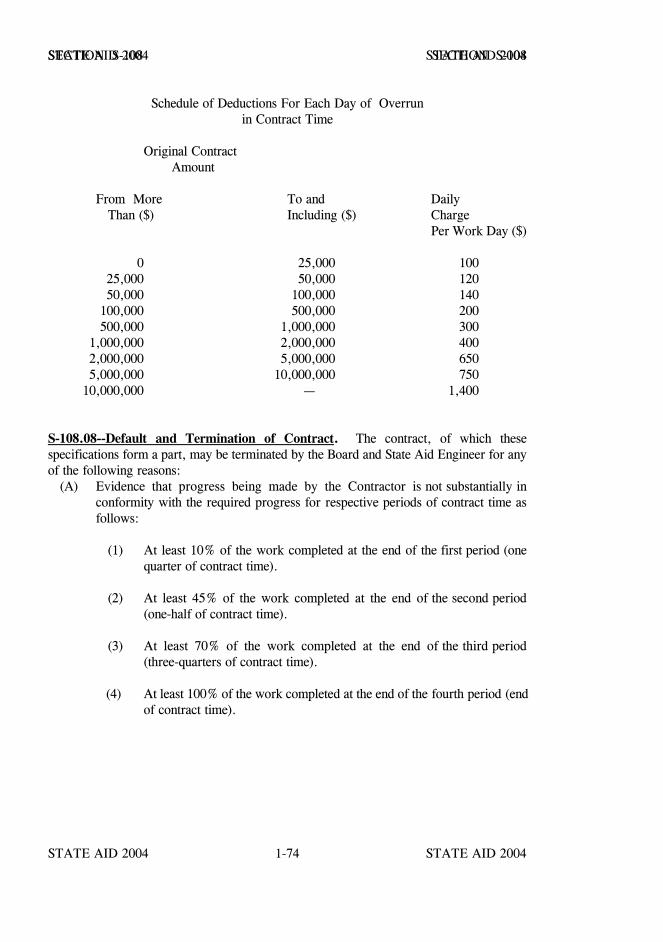
STATE AID 2004 STATE AID 2004
STATE AID 2004 STATE AID 20041-74
SECTION S-108 SECTION S-108
Schedule of Deductions For Each Day of Overrunin Contract Time
Original Contract Amount
From More To and Daily Than ($) Including ($) Charge
Per Work Day ($)
0 25,000 10025,000 50,000 12050,000 100,000 140
100,000 500,000 200500,000 1,000,000 300
1,000,000 2,000,000 4002,000,000 5,000,000 6505,000,000 10,000,000 750
10,000,000 — 1,400
S-108.08--Default and Termination of Contract. The contract, of which thesespecifications form a part, may be terminated by the Board and State Aid Engineer for anyof the following reasons: (A) Evidence that progress being made by the Contractor is not substantially in
conformity with the required progress for respective periods of contract time asfollows:
(1) At least 10% of the work completed at the end of the first period (onequarter of contract time).
(2) At least 45% of the work completed at the end of the second period(one-half of contract time).
(3) At least 70% of the work completed at the end of the third period(three-quarters of contract time).
(4) At least 100% of the work completed at the end of the fourth period (endof contract time).
STATE AID 2004 STATE AID 2004
STATE AID 2004 STATE AID 20041-75
SECTION S-108 SECTION S-108
(B) Failure on the part of the Contractor to proceed with the construction of theproject when so instructed by the Engineer, or to observe any requirements ofthese specifications.
(C) Violation on the part of the Contractor of labor provisions and special regulations.
(D) The Contractor's performing the work unsuitably or neglecting or refusing toremove materials or to perform anew such work as may be rejected orunacceptable and unsuitable.
(E) The Contractor's becoming insolvent or being declared bankrupt or committingany act of bankruptcy or insolvency.
(F) The Contractor's failing to perform the work with sufficient workmen andequipment or with sufficient materials to assure the prompt completion of the work.
(G) The Contractor's discontinuing the prosecution of the work.
(H) The Contractor's allowing any final judgment to stand against him unsatisfied.
(I) The Contractor's making an assignment for the benefit of creditors.
(J) The Contractor's failure for any other cause whatsoever to carry on the work inan acceptable manner.
Before the contract is terminated, the Contractor and his Surety will be notified in writingby the Board and State Aid Engineer of the conditions which make termination of thecontract imminent. If, for any reason, written notice cannot be delivered to the Contractor,notice of termination may be given by publication in a newspaper in the county in which theproject is located; or if there is no such newspaper, the notice may be given by publicationin a newspaper located in Hinds County. If no effective effort has been made by the Contractor or his Surety to correct the conditionsof which complaint is made within 15 calendar days after notice is given, the Board and theState Aid Engineer may declare the contract terminated and notify the Contractor and hisSurety accordingly.
Upon receipt of notice from the Board and State Aid Engineer that the contract has beenterminated, the Contractor shall immediately discontinue all operations.
STATE AID 2004 STATE AID 2004
STATE AID 2004 STATE AID 20041-76
SECTION S-108 SECTION S-108
After termination, the Board and State Aid Engineer will order the Surety to arrange for theprosecution of the work. If the Surety does not proceed with the satisfactory prosecution ofthe work within twenty (20) calendar days from the date on which the contract wasterminated, the Board and the State Aid Engineer may proceed by either readvertising andawarding a new contract, or in any other lawful manner which will provide for thecompletion of the work as planned and set forth in the contract. After the contract has beendeclared terminated, the Surety, or the Board with the approval of the State Aid Engineer,at the Surety's expense, will perform or arrange for necessary maintenance between the dateof termination and the date that work is resumed by arrangement made by the Surety or bythe Board and State Aid Engineer. When the work is finally completed the total cost willbe computed. When this cost, regardless of the method used to complete the work, is lessthan the total cost which would have resulted at the original contract unit prices, thedifference will be paid to the original Contractor's Surety. When the total cost is greaterthan the total cost which would have resulted at the original contract unit prices, thedifference shall be paid by the original Contractor's Surety.
S-108.09--Termination of Contract for Reasons Other Than Default. The Board andState Aid Engineer by and with the consent of the Federal Highway Administration, whereapplicable may by written order, terminate the contract or any portion thereof after deter-mining that for reasons beyond either Board or Contractor control the Contractor is preven-ted from proceeding with or completing the work as originally contracted, and that ter-mination would therefore be in the public interest. Such reasons for termination mayinclude, but need not be necessarily limited to, executive orders of the President relating toprosecution of war or national defense, national or area emergencies which create a seriousshortage of materials, orders from duly constituted authorities relating to energyconservation, and restraining orders or injunctions obtained by third-party citizen actionresulting from national or local environmental protection laws or where the issuance of suchorder or injunction is primarily caused by acts or omissions of persons or agencies other thanthe Contractor.
For purposes of this contract "Area Emergency" shall be understood to be an emergencycreated by an acute shortage of materials, supplies, labor, or equipment within an area inwhich the project is located and termed usually as the "Trade Area."
Specifically for the purpose of this provision, the "Area" under consideration shall beunderstood to be the area from which the Board and State Aid Engineer determines theContractor would reasonably obtain materials, supplies, labor, or equipment, respectively.
When the Board, with the approval of the State Aid Engineer, orders termination of acontract effective on a certain date under this subsection, all completed items of work as ofthat date will be paid for at the contract unit price. Payment for partially completed workwill be made either at agreed prices or by force account as described elsewhere in thesespecifications. Items which are eliminated in their entirety will be paid for as provided inS-109.05.
STATE AID 2004 STATE AID 2004
STATE AID 2004 STATE AID 20041-77
SECTION S-108 SECTION S-108
Acceptable materials, obtained by the Contractor for the work but which have not beenincorporated therein, shall be disposed of as mutually agreed.
After receipt of Notice of Termination under this subsection from the Board and State AidEngineer, the Contractor shall submit, within 10 days of the effective termination date, hisclaim for additional damages or costs not covered herein or elsewhere in these specifications.Such claim may include such cost items as reasonable idle equipment time, mobilizationefforts, bidding and project investigative costs, overhead expenses attributable to the project,legal and accounting charges involved in claim preparation, subcontractor costs not otherwisepaid for, actual idle labor cost if work is stopped in advance of termination date, guaranteedpayments for private land usage as part of original contract, and any other cost or damageitem for which the Contractor feels reimbursement should be made. The intent ofnegotiating this claim would be that an equitable settlement figure be reached with theContractor. In no event, however, will loss of anticipated profits be considered as part ofa settlement. The Contractor shall make his cost records available to the extent necessaryto determine the validity and amount of each item claimed.
Termination of a contract or portion thereof will not relieve the Contractor of his contractualresponsibilities for the work completed, nor will it relieve the Surety of its obligation for andconcerning any just claim arising out of the work performed.
S-108.10--Termination of Contractor's Responsibility. The contract will be consideredcomplete when all work has been satisfactorily completed, satisfactory test reports areavailable on all materials used in the project, the final inspection made, the work acceptedby the Board and State Aid Engineer and the final estimate paid. When the Board and StateAid Engineer write the formal letter of acceptance, the Contractor will be released fromfurther obligation except as set forth in his contract bond or as provided by law.

STATE AID 2004 STATE AID 2004
STATE AID 2004 STATE AID 20041-78
SECTION S-109 - MEASUREMENT AND PAYMENT
S-109.01--Measurement of Quantities. The measurement and determination of quantitiesof each pay item will be made in general as prescribed hereinafter, and specifically as set outunder Method of Measurement and Basis of Payment in the specifications for each pay item.Actual authorized quantities of work completed under the contract will be measured by theEngineer according to United States standard measures, and in accordance with wellrecognized engineering practices. Unauthorized wastage of material will be deducted, andonly quantities actually incorporated in the completed work or ordered to be wasted will beincluded in the final estimate.
A station when used as a definition, term or measurement will be one hundred (100) linearfeet.
Unless otherwise specified, longitudinal measurements for area computations will be madehorizontally, and no deductions will be made for individual fixtures having an area of ninesquare feet or less. Unless otherwise specified, transverse measurements for areacomputations will be the neat dimensions shown on the plans or ordered by the Engineer.
Where the area unit for measurement and payment is specified for erosion control items, themeasurements will be taken on the slope of the ground to compute the actual surface area forpayment.
Structures will be measured according to neat lines shown on the plans or as altered to fitfield conditions.
All items which are measured by the linear foot, such as pipe culverts, guardrail,underdrains, etc., will be measured as specified under the Method of Measurement for theitem unless otherwise shown on the plans.
No payment will be made for unauthorized excavation. Excavation or embankmentperformed beyond the required neat lines, or slope stakes, will not be measured for paymentexcept as elsewhere provided herein or when within tolerances specified.
In computing volumes of excavation and embankment, the average end area method willbe used, unless otherwise specified.
The term gage, when used in connection with the measurement of plates, will mean the U.S. Standard Gage, except that when reference is made to the measurements of galvanizedsheets used in the manufacture of corrugated metal pipe, metal plate pipe culverts andarches, and metal cribbing, the term gage will mean that specified in the AASHTODesignation: M 36 or M 167.
STATE AID 2004 STATE AID 2004
STATE AID 2004 STATE AID 20041-79
SECTION S-109 SECTION S-109
When the term gage refers to the measurement of wire, it will mean the gage specified in theAASHTO Designation: M 32.
The term ton will mean the short ton consisting of 2000 pounds avoirdupois. All materialswhich are specified for measurement by the ton shall be weighed by competent personnel onaccurate, approved scales set at locations approved by the Engineer. If material is shippedby rail, the car weight may be accepted provided the actual weight of material only will bepaid for, and not minimum car weight used for assessing freight tariff. However, carweights will not be acceptable for material to be passed through mixing plants. Trucks usedto haul material being paid for by weight shall be weighed empty daily at such time as theEngineer directs, and each truck shall bear a plainly legible identification mark.
Timber will be measured by the thousand feet board measure (MBM) actually incorporatedin the structure. Measurement will be based on nominal widths and thicknesses and theextreme length of each piece.
When a complete structure or structural unit (in effect, "lump sum" work) is specified as theunit of measurement, the unit will be construed to include all necessary fittings andaccessories.
Volumes of materials computed in cubic yards by the average end area method aredesignated as "Final Measure" (FM), “Final Measure Embankment” (FME) or "PlanMeasure" (PM). Volumes of materials designated for measurement loose in the vehicle aredesignated as "Loose Vehicle Measure" (LVM).
Volumetric measurement of excavation, embankment, granular materials, or similarmaterials in cubic yards will be made by the methods (see below) designated on the plansor in the proposal. For justifiable reasons, such as impracticability of measurement ofvolumes (usually small) by the designated method, the Engineer may order measurement byanother method as follows:
(1) Volumes designated for payment by FM may be measured LVM, andconverted to contract measurement by multiplying the loose measure byeighty percent.
(2) Volumes designated for payment by LVM may be measured at the sourceby the average end area method and converted to contract measurementby multiplying the FM measure by one hundred twenty-five percent.
(3) Volumes designated for payment by FME may be measured in its originalposition by the average end area method and multiply the FM measure by90 percent.
STATE AID 2004 STATE AID 2004
STATE AID 2004 STATE AID 20041-80
SECTION S-109 SECTION S-109
(4) Small volumes of surplus, excess excavation or other small volumes ofexcavation which are impractical to measure by the average end areamethod but are designated to be measured by FME may be measuredLVM and multiply the loose measure by 72 percent.
When any of the above conversion measurements are ordered by the Engineer, the methodof measurement shall be deemed acceptable to all parties and shall be final.
When the average end area method is indicated, other three dimensional measurements ofthe prismoid occupied by the material in its natural position before removal, may be used.
When requested by the Contractor and approved by the Engineer in writing, materialsspecified to be measured by the cubic yard or ton may be converted to the other measure asappropriate. Factors for conversion from weight measurement to volume measurement orfrom volume measurement to weight measurement, will be determined by the Engineer andshall be agreed to by the Contractor before such method of measurement of pay quantitiesis used.
All materials for which measurements are obtained by the cubic yard LVM shall be hauledin approved vehicles and verified therein at the point of delivery. Approved vehicles forthis purpose may be of any size or type acceptable to the Engineer, provided the body isof such shape that actual delivered contents may be readily and accurately determined to thewhole cubic yard. Unless all approved vehicles on the work are of uniform capacity, eachvehicle must bear a plainly legible identification mark, indicating its measured capacity.
All vehicles shall be loaded to a sufficient level to ensure a water level load when thevehicles arrive at the point of delivery. Loads not hauled in approved vehicles, or of aquantity less than the measure quantity for the hauling vehicles, will be subject to rejection.
Bituminous materials will be measured by the gallon or ton. Volumes will be measured at60o F or will be corrected to the volume at 60o F using tables in State Aid’s SOP.
S-109.02--Scope of Payment. The compensation, as herein provided, constitutes fullpayment for the complete work, including all materials, labor, tools, equipment, andincidentals necessary for performing all work contemplated and embraced under the contract;for all loss or damage arising out of the nature of the work; for all loss from the action ofthe elements, except as otherwise provided; for any unforeseen difficulties or obstruction ofthe work which may arise or be encountered during the prosecution of the work until itsfinal acceptance; for all risks connected with the prosecution of the work; for all expensesincurred by or in consequence of suspension or discontinuance of the work as hereinspecified, or for any infringement of patents, trademarks, or copyrights; and for completingthe work in an acceptable manner according to the plans and specifications.
STATE AID 2004 STATE AID 2004
STATE AID 2004 STATE AID 20041-81
SECTION S-109 SECTION S-109
If the "Basis of Payment" clause in the specifications relating to any pay item in the contractrequires that the contract unit price cover and be considered compensation for certain workor material essential to the item, this same work or material will not also be measured orpaid for under any other pay item which may appear elsewhere in the specifications.
The payment of any current estimate, prior to final acceptance of the work by the Boardand State Aid Engineer, shall in no way constitute acceptance of the work, nor in any wayaffect the obligation of the Contractor to repair or renew defective parts of the work. TheEngineer will be the judge of defects or imperfections, and the Contractor shall be liableto the County and State for failure to correct same as provided herein.
S-109.03--Compensation for Altered Quantities. Whenever the quantity of any pay itemis increased or decreased from the original contract quantity, payment for the item will bemade on the basis of the actual quantity completed at the contract unit price, except asotherwise provided in S-104.02, in the detailed specifications for the particular pay itemor by supplemental agreement.
S-109.04--Extra and Force Account Work. Extra work performed in accordance with therequirements and provisions of S-104.03 will be paid for at the unit prices or lump sumstipulated in the agreement authorizing the work, or the Board with the approval of the StateAid Engineer may require the Contractor to do such work on a force account basis to becompensated in the following manner:
(1) Labor. For all labor and foremen in direct charge of the specificoperations, the Contractor will receive the rate of wage (or scale) agreedupon in writing before beginning work for each hour that labor andforemen are actually engaged in such work.
An amount equal to fifteen (15) percent of the sum of the above item willalso be paid the Contractor.
(2) Bond, Insurance, and Tax. For property damage, liability, andworkmen's compensation insurance premiums, unemployment insurancecontributions and social security taxes on the force account work, theContractor will receive the actual cost, to which cost no percentage willbe added. The Contractor shall furnish satisfactory evidence of the rateor rates paid for the bond, insurance, and tax.
(3) Materials. For materials accepted by the Engineer and used, theContractor will receive the actual cost of the materials, includingtransportation charges paid by him (exclusive of machinery rentals ashereinafter set forth), to which cost fifteen (15) percent will be added.
STATE AID 2004 STATE AID 2004
STATE AID 2004 STATE AID 20041-82
SECTION S-109 SECTION S-109
(4) Equipment. For any machinery or special equipment (other than smalltools) authorized by the Engineer, the Contractor will receive the rentalrates agreed upon in writing.
In the event an agreement cannot be reached for a particular piece ofequipment, the pamphlet entitled "Construction Equipment Ownership andOperating Expense Schedule, Region III" as published by theDepartment of Army, U.S. Army Corps of Engineers, current at the timethe force account work is authorized, will be used to determine equipmentownership and operating expense rates. These rates do not includeallowances for operating, labor, mobilization or demobilization costs,overhead or profit, and do not represent rental charges for those in thebusiness of renting equipment. Operating labor and overhead cost willbe allowed. Subject to advance approval of the Engineer, actualtransportation cost for a distance of not more than 200 miles will bereimbursed for equipment not already on the project. The cost oftransportation after completion of the force account work will bereimbursed except it cannot exceed the allowance for moving theequipment to the work.
The hourly use rates are computed on the basis of a 40-hour work week.When the Contractor works more than 40 hours per week, the cost for"Cost of Facilities Capital" will be excluded from the hourly rate forthose hours in excess of 40 hours per week.
No more than eight hours of standby will be paid during a 24-hour day,nor more than 40 hours per week. Standby time will not be allowedunless the equipment has been in idle status in excess of 16 hours duringa 24-hour day. Likewise, standby will not be allowed during periodswhen the equipment would have otherwise been in idle status. Actualoperating time during a week will be credited against the 40 hoursmaximum standby allowance.
All equipment shall be subject to approval from day to day in accordancewith the requirements of S-108.05.
(5) Miscellaneous. No additional allowance will be made for generalsuperintendence, the use of small tools, or other costs for which nospecific allowance is herein provided.
STATE AID 2004 STATE AID 2004
STATE AID 2004 STATE AID 20041-83
SECTION S-109 SECTION S-109
(6) Compensation. No extra work on a force account basis will be paid forunless unit prices for labor, materials, and equipment rentals have beenagreed upon in writing before work is started. In no case shall the unitprices paid to the Contractor exceed the amount of the quoted unit pricefor each item stipulated in the Force Account agreement.
The Contractor, or his authorized representative, and the Engineer shallcompare records of extra work done on a force account basis at the endof each day. Copies of these records shall be made upon the formprovided for this purpose, and shall be certified to by the Contractor andthe Engineer. The Contractor shall furnish to the Engineer itemizedstatements of the cost of all force account work. The statements shallinclude a true copy of the payroll and the original receipted bills andinvoices for the material used and the freight charges paid on same.Where materials used are not specifically purchased for use on extra workbut are taken from the Contractor's stock, the Contractor may submit anaffidavit of the quantity, price, and freight on these materials in lieu ofcertified copies of original bills and invoices. Statements covering forceaccount work for each specific agreement shall be submitted promptly atthe end of the month in which the work was actually completed.
S-109.05--Eliminated Items. Should any item contained in the proposal be foundunnecessary for the proper completion of the work, the Engineer may, upon written orderto the Contractor, eliminate the item from the contract and in no way invalidate the contract.When the Contractor is notified of the elimination of items, he will be reimbursed for actualwork done and all costs incurred prior to the notification as provided in S-104.02.
S-109.06--Partial Payments.
S-109.06.1--General. Monthly estimates will be authorized by the Engineer provided theamount due on completed work is at least $1,000.00 including advancement on materials.The monthly estimate will be prepared by the Engineer on the day of the month prescribedby the State Aid Engineer. Partial payments based on monthly estimates and computed atcontract unit prices will be made on or about the day prescribed by the State Aid Engineer.
If defective work and/or materials are discovered or reasonable doubt arises as to theintegrity of any part of the work for which partial payment has been allowed, a deductionfrom subsequent estimates in an amount equal to the value of the defective or questionedwork will be made until the defects have been remedied or the causes for doubt removed.
STATE AID 2004 STATE AID 2004
STATE AID 2004 STATE AID 20041-84
SECTION S-109 SECTION S-109
S-109.06.2--Advancement on Materials. Partial payments for materials delivered andstockpiled on the project will not normally be made until they are incorporated in the work.
Upon written request of the Contractor, written consent of the Surety, approval by theBoard and the Engineer and the State Aid Engineer reserving the final decision, advancepayments for bulky non-perishable durable materials constituting significant portions of theproject cost stored and stockpiled on or near the project or at other locations approved bythe Engineer may be allowed. Borrow material, granular materials, topsoil, living orperishable plant materials and seeds are not to be considered for partial payment, nor willpartial payments be made on relatively small quantities of materials. If partial payment isallowed, such payment will be based on the verified actual material costs plus the freightcharges (excluding sales tax, local hauling and handling costs) without regard to percentageof completion of work. Estimates will not be allowed until the County Engineer receivesduplicate copies of material invoices plus a testing engineer's certification. In all cases theContractor shall save harmless the Board and State Aid Engineer in event of loss ordamage, regardless of cause, as a result of such advance payments.
As the materials are incorporated into the work in accordance with specification requirementsproportionate reductions for advanced payments shall be made from the monthly estimatescovering the work performed. Calculation of percentage of completion, or rate ofprogress, shall be based on completed work and no consideration shall be given to inclusionof stockpiled materials in such calculations.
S-109.06.3--Retainage. No less than two and one-half percent (2 ½ %) nor more that tenpercent (10 %), as determined by the State Aid Engineer, of the total of each monthlyestimate will be deducted and retained until after the completion of all work in the contract,and the balance, less all previous payments, will be certified by the Engineer. Should theEngineer determine that satisfactory progress and/or performance is not being made on theproject, the percent of retainage may be increased within the above limits with approval ofthe State Aid Engineer. The monthly estimates will be approximate only, and all estimatesand payments will be subject to correction following discovery of error in any previousestimate. When all work has been completed the Engineer may, with the approval of theState Aid Engineer and consent of the Surety, reduce the retainage to two and one-halfpercent of the total amount earned.
Should defective work or materials be discovered or should reasonable doubt arise as to theintegrity of any part of the work completed previously, there will be deducted fromsubsequent estimates an amount equal to the value of the defective or questioned work, andthis work will not be included for payment until the defects have been remedied or the causesfor doubt removed.
STATE AID 2004 STATE AID 2004
STATE AID 2004 STATE AID 20041-85
SECTION S-109 SECTION S-109
S-109.06.4--Withholding of Estimates. An estimate may be withheld indefinitely until alldirections given by the Engineer, in compliance with and by virtue of the terms of thecontract, have been complied with by the Contractor.
S-109.07--Payment for Material on Hand. See S-109.06.2.
S-109.08---Changes in Material Costs. Because of the uncertainty in estimating the costsof petroleum products that will be required during the life of a contract, adjustment incompensation for certain materials is provided as follows:
Bituminous Products-- Each month the Department will acquire unit prices fromproducers or suppliers who supply the State highway construction industry withbituminous products. The average of all quotes for each product will serve as thebase price for contracts let in the subsequent month.
Fuels -- Selected cash price quotations for bulk gasoline and diesel fuel will betaken from Platt's Oilgram PAD 2 and PAD 3. The appropriate adjustment pergallon for gasoline and diesel fuel will be added to the quotations to allow for taxesand markups. The prices thus determined will serve as the base prices for contractslet in the subsequent month.
The established base prices for bituminous products and fuels will be included inthe contract documents under a Notice to Bidders entitled "Petroleum ProductsBase Prices For Contracts Let In (Month and Year)."
Each month thereafter the Engineer will be furnished with the current monthlyprices. Adjustments for change in cost will be determined from the difference inthe contract base prices and the prices for the period that the work is performed andfor the quantities completed provided the price change in a product is more thanfive percent (5%). Adjustments may increase or decrease compensation dependingon the difference between the base prices and prices for the estimate period.
The adjustments will be determined for the quantities of bituminous products andthe average fuel requirements for processing a unit of work as set forth herein.

STATE AID 2004 STATE AID 2004
STATE AID 2004 STATE AID 20041-86
SECTION S-109 SECTION S-109
COST ADJUSTMENT FACTORS FOR FUEL USAGE
Item of Work Units Code DieselGasoline
Excavation & Embankment(Except Structure andFoundation) gallons/cubic yard (E) 0.29
0.15
Granular Materials, gallons/cubic yard (GY) 0.880.57
Stabilizer Aggregates or orCoarse & Seal Aggregates gallons/ton (GT) 0.62
0.40
Subgrade & BaseMixing Items gallons/square yard (M) 0.044
0.028
Hot Mix Asphalt (HMA) gallons/ton (B) 2.570.78
Asphalt Drainage Course gallons/square yard (D) 0.490.15
Portland Cement ConcreteBase & Pavement gallons/square yard (C) 0.11
0.15
Bridge Items, StructuralConcrete, Pipe Culverts,(Including Foundation &Structural Excavation andall other Concrete relateditems) gallons/$1000 (S) 11.0
13.0

STATE AID 2004 STATE AID 2004
STATE AID 2004 STATE AID 20041-87
SECTION S-109 SECTION S-109
CONSTRUCTION MATERIALS
The items and quantities subject to compensation adjustment:
ADJUSTMENT CODE
(A1) Asphalt for HMA mixture -- theoretical gallons based on job mix formula andunit weight of 8.43 pounds per gallon (new asphalt only for recycled HMAmixture).
(A2) Asphalt for Surface Treatment -- pay quantity in gallons.
(A3) Asphalt for Prime -- pay quantity in gallons.
(A4) Asphalt for Curing Seal -- 0.25 gallons per square yard.
(A5) Asphalt for Bituminous Treated Roving -- 0.50 gallons per square yard.
(A6) Asphalt for Asphalt Drainage Course -- theoretical gallons per square yard basedon job mix formula and unit weight of 8.43 pounds per gallon.
Any difference between checked final quantity and the sum of quantities shown on themonthly estimates for any item will be adjusted by the following formula:
FA = (FCQ - PRQ) x EAWhere FA = Final Adjustment
FCQ = Final Checked QuantityPRQ = Total Quantity Previously Reported on Monthly EstimateEA = Total Adjustment Shown on Monthly Estimate
The final adjustment is to consider any error(s) that may have been made in the computationsof monthly adjustments.
After the expiration of contract time, including all authorized extensions, adjustments willbe computed using fuel and material prices that are in effect at the expiration of contracttime.
STATE AID 2004 STATE AID 2004
STATE AID 2004 STATE AID 20041-88
SECTION S-109 SECTION S-109
ADJUSTMENTS
1. Adjustments will be made monthly using quantities shown on theMONTHLY ESTIMATE.
2. No adjustment will be made for price changes less than plus or minus 5%.
3. The adjustment period selected when establishing the Adjusted Base Costwill be the months in which the work was accomplished for the particularitem being adjusted. This period will be entered in the Office of State AidRoad Construction’s monthly computer estimate, by the Engineer,opposite the appropriate item and submitted to State Aid as part of theestimate.
4. Actual monetary adjustments for each item will be made by multiplyingthe Price Differential (either plus or minus) by the number of gallons usedas determined from quantities of work performed during the pay period.
5. No adjustment will be made for items or work accomplished afterexpiration of Contract Time.
S-109.09--Freight Rates and Labor Rates. No allowance or deduction will be made forincrease or decrease in freight rates or demurrage or for any increase or decrease in laborrates unless so stipulated in the special provisions or otherwise provided for.
S-109.10--Payment of Withheld Funds. The Contractor may, with the written consent ofthe Surety, withdraw the whole or any portion of the amount retained by the Board and StateAid Engineer under the provisions of S-109.06.3, by depositing certain securities with theState Treasurer of the State of Mississippi as provided for and in accordance with theprovisions of Section 31-5-15 Mississippi Code, 1972, Annotated.
The Contractor shall make written request to the Board and State Aid Engineer for depositof securities in lieu of retainage. Written consent shall be obtained by the Contractor fromthe Surety and furnished to the Board and State Aid Engineer prior to making deposit withthe State Treasurer.
It will be the responsibility of the Office of State Aid Road Construction to handle the properexchange of information as to funds being held as retainage, records of deposits, andpermissible release of deposit with the State Treasurer in accordance with establishedprocedures.

STATE AID 2004 STATE AID 2004
STATE AID 2004 STATE AID 20041-89
SECTION S-109 SECTION S-109
S-109.11--Acceptance and Final Payment. When the Engineer has determined theContractor has performed all of the work in accordance with the terms of the contract, andthat all test reports are on file, he will notify the State Aid Engineer accordingly, requestingthat the State Aid Engineer make a final inspection of the work. The State Aid Engineer orhis representative shall make such final inspection in company with the Engineer and, ifhe concurs with the Engineer's recommendation that the work be accepted, the Board andthe State Aid Engineer will then formally accept the work in writing and a copy of said letterfurnished the Contractor.
Whenever the work provided for in the contract shall have been completely performed onthe part of the Contractor and all parts of the work have been approved by the State AidEngineer and accepted by the Board and State Aid Engineer, a final estimate showing thevalue of the work will be prepared by the Engineer as soon as the necessary finalmeasurements and computations can be made. The amount of this estimate, less any sumsthat have been deducted or retained under the provisions of the contract, will be paid to theContractor as soon as practicable after the final acceptance. The Board and State AidEngineer may at their discretion withhold final payment until receipt from the Contractor's Surety of a statement consenting to the release of a part of orall of the retainage.
The acceptance by the Contractor of the last payment as aforesaid shall operate as and shallbe a release to the County and State from all claims or liabilities under the contract foranything done, furnished or relating to the work under the contract, or for any act or neglectof said County or State relating to or connected with the contract.
S-109.12--Right to Audit. The Office of State Aid Road Construction reserves the right toaudit the Contractor's records at any time during the contract period and up to three yearsafter the final contract payment or up to three years after any litigation is filed with court,whichever is later. If the Office of State Aid Road Construction commences an audit, theContractor will be required to provide sufficient original documents and records to satisfythe Office of State Aid Road Construction that the costs included in the Contractor's claimwere incurred solely in performance of the referenced project and project phase and werenot incurred on any other project or phase of the referenced project that the Contractor isconstructing or has constructed. The Office of State Aid Road Construction's audit will beconducted in accordance with United States General Accounting Office's GovernmentalAuditing Standards, the Institute of Internal Auditor's Professional Practice Standards, andthe American Institute of Certified Public Accountant's Auditing Standards.
STATE AID 2004 STATE AID 2004
STATE AID 2004 STATE AID 20041-90
SECTION S-109 SECTION S-109
S-109.13--Contract Overpayment(s). The Contractor is duly responsible to and willimmediately reimburse the Office of State Aid Road Construction, without any demandtherefor, for any overpayment(s) of which he has knowledge or through due diligence,should have knowledge.
By the execution of the contract, the Contractor also agrees that if the Office of State AidRoad Construction has made any overpayment(s) to the Contractor on any previouslyexecuted contract(s), the Office of State Aid Road Construction may notify the Contractorin writing of the nature and the amount of the overpayment(s). If the Contractor fails toremit the overpayment(s) to the Office of State Aid Road Construction within thirty (30)calendar days, the Office of State Aid Road Construction may withhold any payment(s) duethe Contractor until said overpayment(s) are received.
STATE AID 2004 STATE AID 2004
STATE AID 2004 STATE AID 20041-91
SECTION S-110 - REQUIRED CONTRACT PROVISIONS
S-110.01--Application. Projects Constructed With Federal Funds.
S-110.02--Payment of Predetermined Minimum Wages. Contract provisions aresupplemented by the Predetermined Wage Rates attached thereto and made a part thereof.The Contractor and his subcontractors, if any, shall pay not less than those rates which havebeen predetermined to be those prevailing on the same type of work on similar constructionin the immediate locality. The wage rates contained in this decision are straight hourly wagerates.
No laborers or mechanics may be employed on the work except in accordance with theclassifications set forth in the schedule mentioned above; provided, however, that in theevent additional classifications are desired, application shall be made by the Contractor tothe Office of State Aid Road Construction for appropriate classifications and rates, and ifthere is urgent need for any additional classification of laborers and mechanics to avoidundue delay in the work, the Contractor may employ such laborers and mechanics at ratesconformable to similar classifications in the wage decision provided he has made writtenapplication to the Office of State Aid Road Construction for a supplemental decision, andprovided further that the Contractor will retroactively adjust, upon receipt of thesupplemental decision, any wages of laborers or mechanics if the rates predetermined exceedthe rates paid by the Contractor.
While the wage rates shown are the minimum rates required by the contract to be paidduring its life, this is not a representation that labor can be obtained at these rates. It is theresponsibility of bidders to inform themselves as to local labor conditions and prospectivechanges or adjustments of wage rates. No increase in the contract price shall be allowed orauthorized on account of the payment of wage rates in excess of those listed herein. Nolaborer or mechanic shall be required to work more than forty hours in any work-weekunless overtime is compensated at one and one-half times his basic rate.
All mechanics and laborers employed or working upon the site of the work shall be paidunconditionally and not less often than once a week, and without subsequent deduction orrebate on any account, the full amounts due at time of payment computed at wage rates notless than those contained in the schedule except such payroll deductions as are permitted byexisting Federal Laws and Regulations, regardless of any contractual relationship which maybe alleged to exist between the Contractor or subcontractor and such laborers and mechanics.
The Wage Determination Decision shall be posted by the Contractor, in the prescribedmanner, at the site of the work in a prominent place where it can be easily seen by theworkers.
STATE AID 2004 STATE AID 2004
STATE AID 2004 STATE AID 20041-92
SECTION S-110 SECTION S-110
The State Aid Engineer may withhold or cause to be withheld from the Contractor so muchof the amount due the Contractor as may be considered necessary to insure payment tolaborers and mechanics employed by the Contractor or any subcontractor on the work thefull amount of wages required by the contract.
The wages of labor shall be paid in legal tender of the United States, except that thiscondition will be considered satisfied if payment is made by a negotiable check, on a solventbank, which may be cashed readily by the employee in the local community for the fullamount, without discount or collection charges of any kind. Where checks are used forpayment, the Contractor shall make all necessary arrangements for them to be cashed andshall give information regarding such arrangements.
No fee of any kind shall be asked or accepted by the Contractor or any of his agents fromany person as a condition of employment on the project.
No laborers shall be charged for any tools used in performing their respective duties exceptfor reasonably avoidable loss or damage thereto.
Every employee on the work covered by this contract shall be permitted to lodge, board,and trade where and with whom he elects and neither the Contractor nor his agents, nor hisemployees shall directly or indirectly require as a condition of employment that an employeelodge, board, or trade at a particular place or with a particular person.
No charge shall be made for any transportation furnished by the Contractor or his agents toany person employed on the work.
S-110.03--Statements and Payrolls.
1. The Contractor and subcontractors shall submit one copy each of FORMSCAD-880, "Weekly Summary of Wage Rates" and CAD-881, "Weekly Statementof Compliance" each week to the State Aid Engineer and to the County Engineer.If submissions of the here-in-before stated forms are delinquent by (14) fourteendays the State Aid Engineer shall hold progress estimates for payment, until therequired completed forms are submitted. Each Contractor and subcontractor shallpreserve his weekly payroll records for a period of three years from the date ofcompletion of the contract.
2. The payroll records shall contain the name, address and social security number ofeach employee, his correct classification, rate of pay, daily and weekly number ofhours worked, itemized deductions made and actual wages paid.
3. The Contractor will make his payroll records available at the project site forinspection by the State Aid Engineer or his authorized representative, and willpermit such representative to interview employees during working hours on the job.
Sections S-111 thru S-199 - Blank.
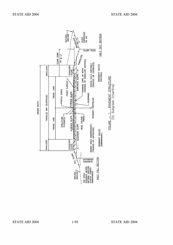
STATE AID 2004 STATE AID 2004
STATE AID 2004 STATE AID 20041-93

STATE AID 2004 STATE AID 2004
STATE AID 2004 STATE AID 2004
STATE AID 2004 STATE AID 2004
STATE AID 2004 STATE AID 2004
SECTION S-200 - EARTHWORK
Section Page
S-200 - MOBILIZATION 2-1
S-201 - CLEARING AND GRUBBING 2-2
S-202 - REMOVAL OF STRUCTURES AND OBSTRUCTIONS 2-5
S-203 - EXCAVATION AND EMBANKMENT 2-8
S-204 - Blank 2-21
S-205 - SUBGRADE PREPARATION 2-22
S-206 - STRUCTURE EXCAVATION FOR CULVERTS, BOXES AND MINOR STRUCTURES 2-24
S-207 - Blank 2-26
S-208 - LINEAR GRADING 2-27
S-209 - Blank 2-29
S-210 - ROADSIDE DEVELOPMENT - GENERAL PROVISIONS 2-30
S-211 - TOPSOILING 2-31
S-212 - GROUND PREPARATION AND FERTILIZER 2-35
S-213 - Blank 2-37
S-214 - SEEDING 2-38
S-215 - MULCHING 2-42
S-216 - thru S-225 - Blank 2-44
S-226 - SOLID SODDING 2-45
S-227 - EXCELSIOR BLANKET 2-48
S-228 - Blank 2-49
S-229 - PAVED DITCHES 2-50
S-230 - BITUMINOUS TREATED ROVING 2-52
STATE AID 2004 STATE AID 2004
STATE AID 2004 STATE AID 2004
Section Page
S-231 - EROSION CONTROL FABRIC 2-54
S-232 - GEOTEXTILE FABRIC STABILIZATION 2-56
S-233 - TEMPORARY SILT FENCE 2-58
S-234 - Blank 2-60
S-235 - TEMPORARY EROSION CHECKS 2-61
S-236 - TEMPORARY SILT BASINS 2-62
S-237 - and S-238 - Blank 2-63
S-239 - TEMPORARY SLOPE DRAINS 2-64
S-240 - GEOGRID REINFORCEMENT OF EMBANKMENT SLOPES AND SUBGRADES 2-66
S-241 - thru S-299 - Blank 2-68
STATE AID 2004 STATE AID 2004
STATE AID 2004 STATE AID 20042-1
SECTION S-200 - MOBILIZATION
S-200.01--Description. Mobilization shall consist of moving all labor, equipment,supplies, and incidentals to the project site and removing same after other work under thecontract has been completed. It shall also include all mobilization preconstruction costswhich are necessary direct costs to the project and are of a general nature rather thandirectly attributable to other pay items.
COMPENSATION
S-200.02--Method of Measurement.
S-200.02.1--Mobilization. Measurement for payment will be in accordance with thefollowing schedule:
(1) When five percent of the original contract amount is earned from otherbid items (exclusive of those listed as dependent items), fifty (50)percent of the amount bid for mobilization, or five percent of theoriginal contract amount, whichever is less, will be paid.
(2) When ten (10) percent of the original contract amount is earned fromother bid items (exclusive of those listed as dependent items), onehundred (100) percent of the amount bid for mobilization, or ten (10)percent of the original contract amount, whichever is less, will be paid.
(3) Upon completion of all work, payment of any amount bid formobilization in excess of ten (10) percent of the original contractamount will be paid.
In the event the contract is terminated under the provisions of S-108.09, the percentageslisted will not be used in computing total payment, but the percentages of original contractamount (exclusive of dependent items) earned at the time of termination will be appliedto the lump sum price bid for mobilization.
S-200.03--Basis of Payment. Mobilization will be paid for at the contract lump sumprice, which shall be full compensation for completing the work specified.
Payment will be made under:
S-200-A: Mobilization - lump sum
When not listed as a pay item, the cost of this work shall be included in the prices bid forother items.
STATE AID 2004 STATE AID 2004
STATE AID 2004 STATE AID 20042-2
SECTION S-201 - CLEARING AND GRUBBING
S-201.01--Description. This work shall consist of clearing, grubbing, removing anddisposing of all things within the limits of the right-of-way and easement areas, exceptthings designated to remain or to be removed in accordance with other provisions of thecontract. This work shall also include the preservation from injury or defacement of allvegetation, objects, or materials designated to remain or to be salvaged, and the removaland satisfactory disposal of obstructions and salvable material when their removal anddisposal is not otherwise provided in the contract. The requirements for removal anddisposal shall be in accordance with the provisions and requirements of S-104.05 andS-202.
CONSTRUCTION REQUIREMENTS
S-201.02--General. The Engineer will establish right-of-way lines, easement lines, anddesignate all trees, shrubs, plants, and other items to remain.
It is the intent of these specifications that all desirable natural growth within theright-of-way and easement areas be preserved where practicable, and that all things whichdetract from the aesthetic value of the completed work, unnecessarily interfere withconstruction, or would unnecessarily interfere with future maintenance be removed. TheContractor shall be responsible for preserving all things designated to be salvaged or toremain. In areas where desirable natural growth is designated to remain, the Contractorshall thin or trim shrubbery and live trees to the extent consistent with the intent of thesespecifications. Use of methods or equipment which might mar or destroy vegetationdesignated for preservation will not be permitted.
All clearing and grubbing necessary for setting construction stakes shall be completed asatisfactory distance ahead of grading operations. Refer to S-107.22.5 for restrictions andprotection of the cleared area.
S-201.03--Clearing and Grubbing.
S-201.03.1--Clearing and Grubbing-Lump Sum Basis. Surface objects, trees, stumps,roots, and other protruding or underground obstructions, not designated to remain, shallbe cleared and grubbed (including mowing, as required). Undisturbed stumps and rootsand nonperishable solid objects which will be a minimum of three feet below subgradeor slope of embankment may be left when authorized by the Engineer. When authorized,stumps and nonperishable solid objects in swampy or wooded areas where mowing is notanticipated may be allowed to remain, provided they do not extend more than six inchesabove the ground line or low water level.
STATE AID 2004 STATE AID 2004
STATE AID 2004 STATE AID 20042-3
SECTION S-201 SECTION S-201
The Engineer may also permit sound stumps to remain outside the construction limitsprovided they are cut off flush with or below the surface of the final ground line.
Except in areas to be excavated, stump holes and other holes from which obstructions areremoved shall be backfilled with suitable material and thoroughly compacted as specified.
All operations shall be conducted in such a manner as to prevent damage to anything thatis to remain on the right-of-way or to adjacent property.
Burning of perishable material shall be done only in accordance with applicable laws,ordinances, and regulations. If not burned, materials and debris shall be removed fromthe right-of-way and disposed of outside the limits of view from any public road orfacility. Locations for disposal shall be obtained by the Contractor in accordance withS-104.06.
Low hanging and unsound or unsightly branches on trees or shrubs designated to remainshall be removed as directed. Branches of trees extending over the roadway shall betrimmed to give a clear height of at least twenty (20) feet above the roadway surface. Alltrimming shall be done by skilled workmen and in accordance with good tree surgerypractices. An approved asphaltum base paint prepared specifically for tree surgery shallbe furnished and applied by the Contractor to cut or scarred surfaces on trees or shrubsselected to remain.
S-201.03.2--Clearing and Grubbing-Area Basis. The scope and method of work shallconform to the provisions and requirements of S-201.03.1, except as specifically providedin Method of Measurement herein below.
S-201.04--Clearing and Grubbing-Bridge Sites. When separate and concurrent gradingand bridge contracts are to be in progress between the termini of construction, clearingand grubbing of the bridge site (Reference definition in S-101.02) shall be theresponsibility of the Grading Contractor, unless the bridge contract contains a pay itemfor clearing and grubbing.
When a contract is let for bridge construction and there is no coincidental grading contractin existence, clearing and grubbing of the bridge site shall be considered as incidental toand included in the bridge items and no separate payment will be made therefor unless apay item for clearing and grubbing is indicated in the contract.
Clearing and grubbing of bridge sites shall conform to the requirements of S-201.03.
STATE AID 2004 STATE AID 2004
STATE AID 2004 STATE AID 20042-4
SECTION S-201 SECTION S-201
COMPENSATION
S-201.05--Method of Measurement.
S-201.05.1--Lump Sum Basis. The area included under this item will be the entire areawithin the right-of-way lines and easements required to construct slopes according to thetypical section shown on the plans. No measurement will be made except when the areaof the right-of-way has been increased or decreased from that shown on the plans whenbids were received.
In this case, the lump sum contract price will be adjusted in the same ratio that the areaof the right-of-way has been increased or decreased.
S-201.05.2--Area Basis. The area included under this item will be measured in acres.Measurement will only be made of the area actually cleared and grubbed and will notinclude areas for which payment is made under another item, or where only grass, weeds,roots, farm crops, and scattered small bushes have been cleared.
Areas acquired for use by the Contractor as haul routes, or areas acquired by theContractor for his own use will not be measured for payment.
S-201.06--Basis of Payment.
S-201.06.1--Lump Sum Basis. This work will be paid for at the contract lump sumprice adjusted when necessary in accordance with the provisions of S-201.05, which priceor adjusted price shall be full compensation for the work as specified.
S-201.06.2--Area Basis. The work under this item, measured as prescribed above, willbe paid for at the contract unit price per acre which shall be full compensation forsatisfactorily completing the work as specified.
S-201.06.3--Exclusion Basis. When the bid schedule of the contract does not containan item of Clearing and Grubbing, the necessary work shall be performed in accordancewith this section, and will not be paid for directly, but will be considered as a subsidiaryobligation of the Contractor under other contract items.
Payment will be made under:
S-201-A: Clearing and Grubbing - lump sum
S-201-B: Clearing and Grubbing - per acre

STATE AID 2004 STATE AID 2004
STATE AID 2004 STATE AID 20042-5
SECTION S-202 - REMOVAL OF STRUCTURES AND OBSTRUCTIONS
S-202.01--Description. This work shall consist of the removal and the satisfactorydisposal of all buildings, fences, structures, old pavements, abandoned pipe lines, andother obstructions which are not designated to remain or to be removed and disposed ofunder other provisions of the contract or under separate contracts or agreements(Reference is made to S-104.06). This work shall also consist of necessary excavationincidental to the removal of structures and obstructions and backfilling the resultingcavity.
CONSTRUCTION REQUIREMENTS
S-202.02--General. The Contractor shall preserve and protect all structures, fences,public and private utilities, and improvements, above or below the ground, which are toremain or be removed by others as set out in S-104.05. Unless specified, removal oradjustment of these items will not be the responsibility of the Contractor. However, theContractor shall arrange and conduct his operations to conform to the requirements set outin S-105.06 and S-105.07.
The Contractor shall raze or remove and satisfactorily dispose of all buildings, structures,fences, and other obstructions, except those items indicated to remain or be otherwiseremoved and disposed of. Basements or cavities left by structure removal shall be filledto the level of the surrounding ground, compacted as directed, or if within the limits ofconstruction, compacted in accordance with S-203.09.3.
All materials not designated for salvage shall be disposed of by the Contractor inaccordance with S-201.03 and S-104.06.
Blasting, if permitted, or other operations necessary for the removal of an existingstructure or other obstruction which may damage new construction shall be completedprior to constructing the new work. The Contractor shall employ methods for removalto ensure that new work, items in place to remain, or materials to be salvaged will not bedamaged (Reference is made to S-107.12).
All material designated for salvage shall be removed, without unnecessary damage, insections or pieces which may be readily transported and shall be stored by the Contractorat designated sites within the project limits.
S-202.03--Removal of Bridges, Culverts, and Other Drainage Structures. Bridges,culverts, and other structures, in use by traffic, shall not be removed until the traffic issatisfactorily accommodated otherwise.

STATE AID 2004 STATE AID 2004
STATE AID 2004 STATE AID 20042-6
SECTION S-202 SECTION S-202
Unless otherwise directed, existing structures shall be removed to at least one foot belowthe final ground line or designated low water level. The removal of portions of bridgeslocated in navigable streams shall be subject to the requirements set out in the permit ofthe authority approving the location and plans and authorizing construction of the newstructure.
Unless otherwise specified in the proposal, or noted on the plans, structural steel, timber,and salvageable material shall remain the property of the County. Steel or timber bridgesshall be carefully dismantled without unnecessary damage. Steel members shall be matchmarked, and all salvaged material shall be stored as specified in S-202.02.
When required on the plans or in the proposal, concrete which is suitable for riprap shallbe salvaged and stockpiled, or otherwise disposed of in accordance with S-202.05.
S-202.04--Removal of Pipe. All culvert pipe designated to be salvaged or relaid shallbe carefully removed and every reasonable precaution taken to avoid breaking ordamaging. Pipes designated to be relaid shall be removed, handled, and stored whennecessary so that there will be no loss or damage before relaying. The Contractor shallreplace without extra compensation all sections lost from storage or damaged bynegligence or improper methods to the extent its reuse is deemed by the Engineer to beunsatisfactory. Pipes not designated to be salvaged or relaid shall be disposed of by theContractor in accordance with S-201.03.1 and S-104.06.
S-202.05--Removal of Pavement, Sidewalks, Curbs, Etc. When required on the plansor in the proposal, concrete pavement, sidewalks, curbs, gutters, etc. designated forsalvage shall be broken into pieces not exceeding 150 pounds in weight unless otherwisespecified and shall be stockpiled at locations designated by the Engineer within the projectlimits or at other locations designated in the contract. All excess over that required forsalvage, and all when none is required for salvage, shall be disposed of by the Contractor,without regard to size of pieces in accordance with S-201.03.
COMPENSATION
S-202.06--Method of Measurement. When the proposal stipulates that payment will bemade for removal of obstructions on a lump sum basis, the pay item, Removal ofObstructions, will include all structures and obstructions encountered within theright-of-way and easement areas shown on the plans and removed and disposed of inaccordance with the provisions of this Section. Where the proposal stipulates thatpayment will be made for the removal of specific items on a unit basis, measurement willbe made by the units stipulated in the proposal.
STATE AID 2004 STATE AID 2004
STATE AID 2004 STATE AID 20042-7
SECTION S-202 SECTION S-202
When pipe removal is shown in the contract as a separate pay item, the length of piperemoved will be in linear feet, computed by multiplying the number of sections removedby their nominal commercial length.
S-202.07--Basis of Payment. Removal of Obstructions, Pay Item No. S-202, will bepaid for at the contract lump sum price which shall be full compensation for removing anddisposing of the obstructions in accordance with the provisions of the contract.
Specific obstruction items stipulated for removal and disposal under Pay Item Nos.S-202-A, S-202-B, S-202-C and S-202-D, will be paid for at the contract unit price bidper unit specified in the proposal, which shall be full compensation for satisfactorilycompleting the work specified.
Payment will be made under:
S-202-A: Removal of Obstructions - lump sum
S-202-B: Removal of - per unit(Item)
S-202-C: Removal of - per linear foot (Item)
S-202-D: Removal of - per square yard(Item)
S-202-E: Removal of Pipe (All Sizes) - per linear foot
STATE AID 2004 STATE AID 2004
STATE AID 2004 STATE AID 20042-8
SECTION S-203 - EXCAVATION AND EMBANKMENT
S-203.01--Description. This work shall consist of excavation and embankmentrequired for the roadway, ditches, channel changes, and borrow material, and includesthe preparation of subgrade and foundations, the construction of embankments and otherutilization or disposal of materials excavated, and the compaction and dressing ofexcavated areas and embankments.
S-203.02--Classifications of Excavation. Where classification is provided by separatepay items in the proposal, the excavation specified under this section may be classifiedby any of the following classes:
S-203.02.1--Unclassified Excavation. When no pay item is included in the contract forother classes of excavation, unclassified excavation will consist of the excavation andprocessing or disposal of all materials of whatever character encountered in the work.When pay items are included for other classes of excavation, unclassified excavation willconsist of the excavation and processing or disposal of all materials except those for whichadditional pay items are provided.
S-203.02.2--Rock Excavation. When shown as a pay item, rock excavation will consistof material which cannot be excavated without blasting and shall also include boulders anddetached stones having a volume of one-half cubic yard or more each. The use of thewords "rock," "boulders," or "stone," or synonyms of these words appearing elsewherein these specifications does not imply that these materials may be included under thisclassification unless so indicated in the contract.
The Contractor shall immediately notify the Engineer when rock excavation isencountered during the progress of the work so the necessary measurements may be madefor determining the volume removed.
S-203.02.3--Muck Excavation. When shown as a pay item, muck excavation willconsist of the excavation, removal, and disposal of natural deposits of saturated orunsaturated mixtures of soils and organic matter unsuitable for foundation materials. TheState Aid Engineer, after consideration of the material and the conditions involved at thetime of excavation, will be the sole judge as to whether the material involved will beclassified as muck excavation.
S-203.02.4--Borrow Excavation. Borrow excavation will consist of approved materialrequired for the construction of embankments or other portions of the work. TheContractor shall make arrangements for obtaining borrow, and shall pay all costsinvolved. Contractor furnished borrow shall meet the requirements of S-106.02 andS-703.21.
STATE AID 2004 STATE AID 2004
STATE AID 2004 STATE AID 20042-9
SECTION S-203 SECTION S-203
S-203.02.5--Channel Excavation. When shown as a pay item, channel excavation willconsist of excavation and disposal of all material required for the widening, deepening,or straighteningof an existing channel or the construction of a new channel. Material from channelexcavation used in the roadbed or other required embankment construction will beclassified as unclassified excavation.
S-203.02.6--Special Excavation. When shown as a pay item, special excavation willconsist of the excavation and disposal of the following: unsuitable materials required tobe removed below natural ground under embankments; unsuitable materials encounteredin soils not placed under this contract; or excavation below required embankmentsspecified for the salvaging and stockpiling of topsoil and plating material.
S-203.02.7--Excess Excavation. When shown as a pay item, excess excavation willconsist of excavation which cannot be satisfactorily used or disposed of within theright-of-way. Except for muck excavation, excess excavation may include any type,kind, or class of excavation which the Engineer determines must be removed from theright-of-way. It will not include any excess caused by the Contractor importing too muchexcavation from sources outside the roadway structure; in this case the excess excavationshall be removed from the right-of-way at the expense of the contractor. (Refer toS-104.07)
When shown as a pay item and unless otherwise indicated in the contract, the Contractorshall provide a disposal area for excess excavation.
S-203.02.8--Surplus Excavation. When shown as a pay item, surplus excavation willconsist of required excavation within the right-of-way, which is in excess of or unsuitablefor that required for embankments and which can be satisfactorily used or disposed ofwithin the right-of-way.
S-203.02.9--Stripping Excavation. Stripping excavation shall consist of the excavation,removal and disposal of all overburden materials of whatever character necessary tosatisfactorily expose suitable selected material.
S-203.02.10–Estimated On Site Excavation (E.O.S.E.). Where projects cannot bebalanced from material from within the right-of-way, excavation identified as EstimatedOn Site Excavation (E.O.S.E.) shall become the property of the contractor. It shall beexcavated, used in the embankment if suitable, and paid for as Borrow Excavation(F.M.E.), if used in the embankment.
STATE AID 2004 STATE AID 2004
STATE AID 2004 STATE AID 20042-10
SECTION S-203 SECTION S-203
CONSTRUCTION REQUIREMENTS
S-203.03--General. Excavation and embankment operations may be started at thelocation and in the sequence approved by the Engineer when:
(1) sufficient clearing and grubbing has been completedand accepted;
(2) the work has been cross sectioned and slope staked;(3) installation of required pipes, culverts, and approved
backfills are complete;(4) the site has been prepared in accordance with these
specifications;(5) the Contractor has informed himself as to the proper
haul and disposal of material.
Excavations and embankments shall be finished to reasonably smooth and uniformsurfaces. No material shall be wasted without permission of the Engineer. Excavationoperations shall be conducted so that material outside the limits of slopes will not beunnecessarily disturbed.
Where plating is contemplated, either in cut or fill sections, appropriate adjustment shallbe made in the graded section during construction so that the finished section after platingwill conform within allowable tolerances to the typical sections shown on the plans.
Unless otherwise specified, rock larger than three inches shall be removed to a minimumdepth of eight inches below subgrade within the limits of the roadbed, and the excavationbackfilled with material designated on the plans or approved by the Engineer. Care shallbe taken that undrained pockets are not left in the surface of rock. Rock removed morethan 12 inches below subgrade will not be measured for payment. The backfilling of thisdepth in excess of 12 inches will be at the expense of the Contractor.
Borrow material should not be placed until after excavation from the roadway has beenplaced in embankments. Excess material determined to have been caused by theContractor importing too much excavation from sources outside the roadway shall beremoved from the right-of-way in accordance with S-104.06 unless the Engineer ordersthat the material be disposed of within the right-of-way. In either case, the volume ofexcess material will be measured by the method deemed most appropriate by the Engineerunder the provisions of S-109.01 and deducted from measured quantities. The Contractorshall not excavate beyond the dimensions and elevations established or approved, and nomaterial shall be moved prior to the staking out and cross-sectioning of the site.

STATE AID 2004 STATE AID 2004
STATE AID 2004 STATE AID 20042-11
SECTION S-203 SECTION S-203
Additional requirements shall be those applicable conditions governing the use of localmaterials as set out in S-106.
Obliteration of old roadways shall include all operations necessary to incorporate the oldroadway into the new roadway or into the surrounding right-of-way in a way that willprovide a pleasing appearance from the new roadway. Unless other pay items areprovided, roadway obliteration will be paid for as unclassified excavation.
When the Contractor's excavating operations encounter remains of prehistoric dwellingsites or other artifacts of historical or archeological significance, the operations shall betemporarily discontinued. The Engineer will contact appropriate authorities to determinethe disposition thereof.
When directed by the Engineer, the Contractor shall excavate the site in a manner topreserve the artifacts encountered, and if required shall remove them for delivery to thecustody of the proper State authorities. Such excavation will be considered and paid foras extra work.
Where excavation to grade results in a foundation, subgrade, or slope of unsuitable soil,the Engineer may require the Contractor to remove unsuitable materials and backfill tothe required grade with approved material. Slides or other soil failures shall be removedby the Contractor unless their removal is waived by the Engineer. The Contractor shallconduct his operations in such a way that the Engineer can take the necessary crosssections before backfill is placed.
The Engineer may designate as unsuitable those soils which cannot be properly compactedunder satisfactory conditions. All unsuitable material shall be disposed of as specified ordirected.
When the contract requires, or the Engineer orders, excavation to be handled more thanone time prior to final placement (such as topsoil to be stockpiled and reserved for lateruse), this excavation will be paid for at the contract unit price for the class excavationinvolved for each handling approved by the Engineer, or will be paid for as another itemof work for the final handling when so specified.
S-203.04--Topsoil. Where the salvaging and stockpiling of topsoil or plating material isspecified, this operation shall be completed before beginning excavation of the underlyingmaterial.
S-203.05--Construction of Bridge Approaches. The construction of "spill through"embankments and approaches shall be the responsibility of the grading contractor. Theexistence of a separate contract awarded for bridge construction will not alter thisresponsibility.
STATE AID 2004 STATE AID 2004
STATE AID 2004 STATE AID 20042-12
SECTION S-203 SECTION S-203
At each approach, the Grading Contractor shall construct and finish as soon as practicablesections of the embankment or approaches extending a minimum of 100 feet from eachbridge end.
The allowable tolerance for initial construction of bridge end slopes to be paved will beplus six inches, but all other bridge end slopes shall be finished to the lines and gradesspecified.
Prior to installation, the Bridge Contractor shall properly shape the area to be coveredwith slope paving. He shall drive piling through the fill, complete the end bents, endspans, and slope paving as soon as practicable after the bridge end fills have been placedin order that the grading may be completed by the grading contractor. (Reference is madeto S-105.07 and S-201.04).
S-203.06--Excavation Operations. Excavation operations shall be so conducted as tominimize the loosening of materials outside the required slopes or below the indicatedgrade. No payment will be made for the removal, disposal, or replacement of materialdetermined to be loosened or undercut through carelessness or negligence on the part ofthe Contractor. Neither will payment be made for excavation which is used for purposesother than designated.
When practicable, excavation and disposal of the material shall be conducted in such amanner that the most suitable material will be placed in the top courses of embankments.Adequate drainage which will conform to the finished drainage system shall bemaintained.
All earth cut slopes shall be dressed to smooth and uniform surfaces to conform to thespecified sections. Allowable tolerances for cut slopes shall be plus or minus five-tenths(0.5) foot horizontally at subgrade elevation. On deep cuts, a greater tolerance isallowable but not to exceed an additional three-tenths (0.3) foot horizontally for each ten(10) feet of depth. Allowable vertical tolerances at subgrade elevation shall be plus orminus 0.10 foot in elevation.
Care shall be taken to avoid overshooting in all material which requires blasting. All rockcut slopes shall be left with a reasonably uniform surface and all loose, shattered, orover-hanging rock shall be removed.
S-203.07--Muck Excavation. The depth and width of the muck excavation will normallybe shown on the plans, and the excavation and subsequent basement soil formation shallbe completed as soon as practicable in order to obtain maximum consolidation prior todesign soil, subbase, base, and pavement construction. When directed by the Engineer,other unsatisfactory foundation material directly beneath or immediately adjacent to muckshall be removed and its removal and disposal included as muck excavation. Excavationof muck shall begin at one end and proceed ahead of backfilling or embankmentoperations for the full width and depth shown on the plans or as directed.
STATE AID 2004 STATE AID 2004
STATE AID 2004 STATE AID 20042-13
SECTION S-203 SECTION S-203
Placing of embankment material in the excavated area by backdumping may be permittedwhen the Engineer determines this method of placement to be satisfactory. In this case,placement shall immediately follow the muck removal, and where deemed desirable, thefill shall be carried forward in a wedge shape carrying as high a surcharge above gradeas practicable to afford maximum efficiency in displacing the remaining muck.Otherwise, embankment construction shall be performed in accordance with theprovisions of S-203.09.
Pressure developed on the advancing toe of the embankment by in-place or displacedmuck shall be relieved by excavating and removing the muck. Stream channels ordrainage ditches that may be filled by movement of the muck shall be cleaned outimmediately. Displaced materials adjacent to the roadway shall be leveled or disposed ofas specified. In any case, the material shall be left in such a manner that it will notpresent an unsatisfactory appearance, interfere with essential drainage, or prevent properembankment formation.
The Engineer may permit the Contractor to use explosives in accordance with theprovisions of these specifications to liquify the muck sufficiently to be displaced by theadvancing embankment. Unless otherwise specified, no extra payment will be allowedfor materials and labor necessitated by blasting.
S-203.08--Disposal of Unsuitable, Surplus, Channel, and Excess Excavation. Allmaterial encountered in excavation within the right-of-way which is unsuitable for use inthe work shall be removed and disposed of as specified in the contract or as directed.Unsuitable material shall be understood to be any material, which at the proper moisturecontent cannot be processed to the required density and stability. Unless otherwisespecified, the Contractor shall provide at his own expense the location for the disposal ofmuck and excess excavation, and shall furnish the Engineer with two signed copies of therelease as provided in S-104.06.
Surplus excavation as defined in S-203.02.8 shall be used for uniformly wideningembankment, for flattening slopes, or in other places within the right-of-way for thepurpose indicated. If there is more surplus excavation than can be effectively used withinthe right-of-way, the Engineer will reclassify the surplus as excess excavation as definedin S-203.02.7 which shall be disposed of off the right-of-way as provided in the contract,or as extra work.
Unless specified for use in embankments, channel excavation may be used to fill oldchannels, washes, gullies, or wasted as directed. It shall be spread and leveled orotherwise shaped to blend with the adjacent terrain and shall not obstruct drainage,interfere with the property rights of others, or present an unsatisfactory appearance.
STATE AID 2004 STATE AID 2004
STATE AID 2004 STATE AID 20042-14
SECTION S-203 SECTION S-203
Except for material indicated on the plans and measured for payment under another payitem, the Contractor will be paid for both the unsuitable material ordered excavated anddisposed of and the material required for backfill at the respective contract prices.
S-203.09--Embankment Construction.
S-203.09.1--General. Embankment construction shall consist of: constructing roadwayembankments; dikes; placing and compacting of approved material where unsuitablematerial has been removed; backfilling of structures where not otherwise provided for;and placing and compacting embankment material in holes, pits, or other depressions.
This work shall also consist of preparation of the areas upon which embankments are tobe constructed. Only approved materials excavated as provided in the contract shall beplaced in embankments and backfills; unsuitable or perishable materials such as rubbish,sod, brush, roots, loose stumps, logs, heavy vegetation, sawdust, etc. shall not beincorporated in embankments. Rocks, broken concrete, or other solid material shall notbe placed in embankment areas where piles are to be driven.
Special materials for embankments such as for inundated areas, filter beds, etc. orspecial backfill material may be specified elsewhere in the contract.
S-203.09.2--Preparation of Embankment Areas. Preparation of embankment areasshall be in accordance with one or a combination of the following procedures:
S-203.09.2.1. All grade points shall be undercut, back-filled with suitable excavationmaterial, and compacted to the density for the design soil portion of embankments.The material excavated from the undercut, if suitable, shall be used in other portionsof the work. The undercut at each grade point shall be approximately three feetbelow the subgrade in the embankment. The undercut shall be extended a sufficientdistance into the cut to provide an undercut grade at the point of intersection with thesubgrade of not less than three feet below natural ground. Approved undercut willbe measured for payment as excavation.
S-203.09.2.2. Where a compacted old road surface containing granular materials orsurface treatment is within three feet below subgrade, the old road surface shall bescarified as directed. The loosened material shall be compacted to the densityspecified (SV) for the design soil portion of the embankment prior to placingadditional material.
STATE AID 2004 STATE AID 2004
STATE AID 2004 STATE AID 20042-15
SECTION S-203 SECTION S-203
S-203.09.2.3. Unless otherwise specified or directed by the Engineer, where theheight of an embankment to subgrade will be three feet or less, all sod, vegetablematter, and unsuitable soil shall be removed from the surface upon which theembankment is to be constructed. The cleared surface shall be completely broken upby plowing, scarifying, or disk-harrowing to a depth of at least six inches Theloosened material shall then be compacted to the density specified (SV) for the designsoil portion of the embankment.
The removed vegetation and unsuitable soil shall be disposed of as directed. Nomeasurement for payment for removal will be made unless the Engineer requires thatthe material be loaded and hauled for use or disposal in another area. In this case,measurement for payment will be made as provided in S-203.12.
No direct payment will be made for plowing, scarifying, or disk-harrowing underthis type of preparation.
S-203.09.2.4. In areas where the height of embankment to subgrade is to be greaterthan three feet, all material determined by the Engineer to be unsuitable forfoundation for the embankment shall be undercut and disposed of as directed. Allsod on all other areas shall be thoroughly disk-harrowed before construction of theembankment. Approved undercut will be measured for payment as excavation. Nodirect payment will be made for disk-harrowing under this type of preparation.
S-203.09.2.5. Where embankment is to be constructed on hillsides or againstexisting roadway slopes, slopes which are steeper than 4:1 shall be continuouslybenched as the new work is brought up against the slope. Benching shall be ofsufficient width to permit operation of placing and compacting equipment. Eachhorizontal cut shall begin at the intersection of the original ground or slope and thevertical sides of the previous cut. Material thus cut out shall be recompacted alongwith the new embankment material and will not be measured for payment.
S-203.09.3--Embankment Formation. After the area has been prepared as specified,the embankment shall be constructed in full width layers parallel to the finished grade.
Except as herein provided, each layer shall not exceed eight inches (loose) in thickness,and shall be spread, shaped, and compacted so that the completed embankment willconform to the required density, stability, line, grade, and cross-section.
STATE AID 2004 STATE AID 2004
STATE AID 2004 STATE AID 20042-16
SECTION S-203 SECTION S-203
The required stability in embankment construction shall be that which the Engineerdetermines can be reasonably obtained at the proper moisture content for the materialbeing placed. Sponginess, shoving, or other displacement under heavy equipment willbe considered prima facie evidence of lack of stability under this requirement.
Direct casting or similar methods will not be permitted unless authorized in writing by theEngineer. Should direct casting be authorized, all cast material shall be moved from thepoint where it is deposited, spread and compacted in uniform layers as specified herein.
S-203.09.3.1--Basement Soils . In low, swampy ground which will not support theweight of hauling equipment, the Engineer may permit the bottom portion of theembankment to be constructed in a uniformly distributed layer of sufficient thickness tosupport equipment placing subsequent layers. However, this method will not be permittedin any portion of the fill less than three feet below subgrade. (Reference Figure 1.S-100).
In areas where the embankment material is of a highly varying character, constructionshall be performed so as to eliminate pockets or strata of varying materials. Each layershall be disk-harrowed and heavily bladed for its full depth; or moved from its positionof deposit by motor grader, bulldozer, or other equipment; or processed by other meansto the extent necessary to eliminate pockets or strata of material of varying character.The layer shall then be shaped and compacted in accordance with these specifications.
Rock in embankment shall be distributed over the area to avoid bridging, nests, orpockets, and all interstices shall be completely filled with earth or stone fragments andcompacted. Where only occasional boulders are encountered, they shall be placednear the outer slopes in lower portions of the embankment.
Where the excavated material consists predominately of rock fragments of sizes thatcannot be placed in layers of the thickness specified without crushing, pulverizing, orfurther breaking down of pieces resulting from excavation methods, the material may beplaced in layers not exceeding the thickness of the approximate average size of the rocks.The balance of the embankment shall be composed of suitable material placed in layersnot exceeding eight inches in loose thickness and compacted as specified.
S-203.09.3.2--Design Soils. Each layer of the design soil shall be disk-harrowed andheavily bladed for its full depth, or processed by other approved means to the extentnecessary to provide a layer of material reasonably uniform in character. Each layer shallthen be shaped and compacted in accordance with these specifications. (ReferenceFigure 1. S-100).
STATE AID 2004 STATE AID 2004
STATE AID 2004 STATE AID 20042-17
SECTION S-203 SECTION S-203
S-203.09.3.3--Backfill and Embankment Formation Adjacent to Structures.Backfilling around structures shall not start until the structure has been properly cured forthe minimum number of days required and permission has been granted by the Engineerto proceed with the work. The work shall be performed only under the direct supervisionof the Engineer or his designated representative.
Material used shall be suitable material obtained from structure excavation or fromroadway and drainage excavation or other designated material. The material shall beapproved before placement, and shall be the best available from the sources. It shallpreferably be nonplastic, sandy, or loamy earth and shall be free from large lumps,clods, rock, or other objectionable matter. Adequate provision shall be made for thoroughdrainage of all backfilling.
The backfill material shall be deposited in uniform, parallel layers on the sides of boxbridges or culverts, or other structures. Each layer shall be disk-harrowed and bladedfor its full depth or processed by other approved means to the extent necessary to providea layer of material reasonably uniform in character, and shall be so placed andcompacted that drainage of the layer will be away from both the longitudinal and thetransverse axes of the structure. In addition, the backfill for abutments, retaining walls,wing walls, or other structures or sections thereof shall be built in layers with each layerbeing constructed for the full length of the unit and special precaution shall be taken toprevent any wedging action against the structure.
The material for each layer shall be uniformly compacted, preferably by approvedmechanical equipment including self-powered mechanical tampers, to not less than thedensity required in the adjacent embankment. The work shall be conducted so as to forma berm of compacted soil of sufficient width on each side of the structure such that theberms at the top of the structure shall be at least six feet in width. The slopes of thebackfill shall not be steeper than 2:1 at any point. Unless otherwise specified, backfillingshall continue to the level of the original ground, to an elevation at least one foot abovethe top of the structure, or to the top of the graded section, as applicable.
The work shall be conducted in a manner so that the Engineer can make the necessarytests for compaction as the work progresses.
The Contractor shall repair, restore with new work, or make good without extracompensation all damage done to the structure as a result of the backfilling operations.
Payment for this construction is included in the contract unit price for the material withwhich backfill is made.
STATE AID 2004 STATE AID 2004
STATE AID 2004 STATE AID 20042-18
SECTION S-203 SECTION S-203
S-203.09.4--Compaction of Embankments. All embankment material shall be at themoisture content determined to be proper for the particular material being placed so thatthe resulting work will be both dense and stable.
It shall be the Contractor's responsibility to maintain the proper moisture content duringcompaction operations, and the Engineer may require moistening or drying as necessary,without additional compensation to the Contractor.
The material shall be compacted until the required density, determined in accordance withS-700.03 and S-700.04 has been attained and the embankment is stable.
Acceptance of compaction will be on a lot basis. A lot size will be based on theContractor's hourly production rate as set out in State Aid’s SOP.
For basement and design soils, the required density shall be 95.0 percent and 98.0percent, respectively. If a density test fails within minus two percent (-2.0%), 93.0 to95.0% or 96.0 to 98.0%, of the required density, a verification test will be performed andthe average of the two tests will be the test value for the lot. If this test value does notmeet the required density (95.0 or 98.0%), the lot shall be rejected. If the original testvalue exceeds minus two percent (-2%) of the required density, no verification test willbe performed and the lot shall be rejected.
Acceptance of compaction for structural backfill will be considered a separate frame ofwork. The backfill at each structure up to a depth of five feet will be considered a lot.For long structures, the Engineer may specify that the backfill be divided into smaller lots.Each lot will be divided into four approximately equal sublots with two density tests takenat random on each side of the structure. The single test and the lot average shall conformto the required densities set forth above for basement soils or design soils as applicable.
The Contractor shall make allowance for shrinkage and compaction in the construction ofembankment.
S-203.09.5--Tolerances. The tolerances shown below as allowable shall not prevent thework from meeting the requirements of S-105.03. The allowable vertical tolerance atsubgrade elevation shall be plus or minus one-tenth foot in elevation.
The allowable horizontal tolerance at subgrade elevation will be five-tenths of a foot. Theallowable tolerance from staked slopes on fills will be plus or minus five-tenths foothorizontally for each 10 feet of fill height except where surplus excavation is required orpermitted by the Engineer to be used for uniformly widening embankments or flatteningslopes. In these cases tolerances will be modified accordingly.
STATE AID 2004 STATE AID 2004
STATE AID 2004 STATE AID 20042-19
SECTION S-203 SECTION S-203
S-203.10--Settlement by Blasting. The procedures for formation and enforcedsubsidence of embankment through muck areas by blasting will be designated elsewherein the contract when such methods are required.
S-203.11--Maintenance of Earthwork. The Contractor shall satisfactorily maintain allportions of the work until the completion and acceptance of the contract. (Reference ismade to S-105.14, S-105.15, and S-105.16). The Contractor shall replace, restore, orreconstruct without extra compensation all portions, including materials, determined bythe Engineer to have been displaced or damaged due to carelessness or negligence on theContractor's part. Carelessness or negligence may include but not be limited toinadequate drainage; failure to remove forms or obstructions; failure to properly prosecuteand complete work within the time specified in the contract; neglecting to establish erosioncontrol items; failing to provide continuous maintenance as required under S-105.14; orother avoidable causes for displacement or damages.
If the Engineer determines that the work has been properly prosecuted, constructed,protected, and maintained and earthwork damage is caused by the action of the elements,the Contractor may be paid at the contract unit prices for excavation material , ifapplicable, required in making repairs.
COMPENSATION
S-203.12--Method of Measurement. Items of excavation listed in the proposal will,unless otherwise stipulated, be measured as follows:
S-203.12.1--Final Measurement (FM). Whenever this method of measurement is used,the excavation will be measured in its original position and the material actually removed,as ordered as hereinbefore prescribed, shall be computed by the method of average endareas of the sections by plotting or superimposing the final cross-section elevations andmeasurements onto the original plan cross-sections.
S-203.12.2--Plan Measurement (PM). Whenever this method of measurement is used,cross-section templates, reflecting the grades, slopes and sections shown in the originalplans, will be plotted or superimposed onto the original plan cross-sections. Theexcavation volume delineated by these cross-section templates will then be computed bythe method of average end areas. If the excavation and embankment work can becompleted according to the grades, slopes and sections shown on the original plans, thenthe quantity computed as set out above and shown on the original plans will be themeasurement for final payment.
STATE AID 2004 STATE AID 2004
STATE AID 2004 STATE AID 20042-20
SECTION S-203 SECTION S-203
If, during construction, however, the Engineer finds it necessary to change the grades,slopes and sections to effect a balancing of excavation and embankment quantities, or ifsuch changes are ordered for any other reasons, cross-section templates reflecting therevised grades, slopes and sections will likewise be plotted or superimposed onto theoriginal plan cross-sections. The excavation volume, delineated by these revisedsections, will then be computed by the method of average end areas and the revisedquantities so computed and reflecting any increased or decreased volume will be themeasurement for final payment.
The Engineer reserves the right to measure the completed work, in whole or in part, byFinal Measurement (FM) in which case the Final Measurement method shall govern.
Plan Measurement (PM) shall not be used for channel changes, bridge abutments or otherisolated areas of excavation.
S-203.12.3--Loose Vehicle Measurement (LVM). Whenever this method ofmeasurement is specified, the excavation will be measured in the hauling vehicle at thepoint of deposit, in accordance with S-109.
S-203.12.4--Muck Excavation. Measurement for muck excavation will be made as forother excavation when practicable. When ordinary methods of measurement are notpracticable, the volume of muck excavation shall be the actual volume of the prism ofearth required to construct the embankment up to an elevation coincident and parallel tothe original ground line of the muck area, as determined by borings during theconstruction or after completion of the embankment.
S-203.12.5--Rock Excavation. When the contract contains an item of rock excavation,the Contractor shall immediately notify the Engineer when rock excavation, as defined,is encountered during the progress of the work, so that the necessary measurement maybe made for determining the volume removed.
S-203.12.6--Undercut. Undercut required by the Engineer prior to replacement ofembankment material that is unsuitable for placement in outer portions of embankmentslopes will be measured by the cubic yard (FM).
S-203.12.7--Final Measurement-Embankment (F.M.E.). Required embankmentconstructed of Borrow Excavation (F.M.E.), properly constructed, maintained andaccepted, will be measured in its final position by the cubic yard, average end areamethod, within allowable tolerances, complete-in-place. Subsidence if it occurs will notbe measured for payment.
STATE AID 2004 STATE AID 2004
STATE AID 2004 STATE AID 20042-21
SECTION S-203 SECTION S-203
S-203.13--Basis of Payment. Items in this section, measured in accordance withS-203.12, will be paid for at the contract unit price per cubic yard, which shall be fullcompensation for completing the work as specified except that payment for ContractorFurnished Borrow material will also include additional requirements as specified inS-106.02.2.
Payment will be made under:
S-203-A: Unclassified Excavation ( ) - per cubic yard PM, FM or LVM
S-203-B: Rock Excavation ( ) - per cubic yard FM or LVM
S-203-C: Blank
S-203-D: Muck Excavation (FM) - per cubic yard
S-203-E: Borrow Excavation (Contractor Furnished LVM, Class ) - per cubic yard
S-203-E1: Borrow Excavation (F.M.E.) (Contractor Furnished) (Class ) - per cubic yard
S-203-F: Channel Excavation ( ) - per cubic yard FM or LVM
S-203-G: Special Excavation ( ) - per cubic yard FM or LVM
S-203-H: Excess Excavation ( ) - per cubic yard FM or LVM
S-203-I: Surplus Excavation ( ) - per cubic yard FM or LVM
S-203-J: Stripping Excavation (FM) - per cubic yard
Section S-204 - Blank.
STATE AID 2004 STATE AID 2004
STATE AID 2004 STATE AID 20042-22
SECTION S-205 - SUBGRADE PREPARATION
S-205.01--Description. The subgrade is designated as that part of the roadbedconsisting of the design soils upon which the base structure or a surface course is to beplaced and its finished construction shall conform to the provisions herein and such specialpreparation as may be required for the particular base structure or surface course to beconstructed. The subgrade preparation shall consist of the construction and compactionof the subgrade in accordance with these specifications.
S-205.02--Subgrade Preparation. The subgrade shall be constructed as indicated abovein accordance with S-700.04.3 and with the lines, grades and typical section for theparticular type of base structure, or surface course as shown on the plans or establishedby the Engineer. No base structure, or surface course shall be placed on the subgradeuntil same has been checked and approved by the Engineer.
The subgrade material shall be moistened or dried to the optimum moisture content asdetermined by AASHTO T-99, Method C, as modified by Mississippi Test MT-8.
The specified value (SV) for subgrade density shall be ninety-eight (98) percent. A unitof deviation will be one percentage point. Field density determinations will be made inaccordance with AASHTO T-191, as modified by Mississippi Test MT-10 or MT-16.
All soft and yielding or other unsuitable material which will not compact readily shallbe removed and disposed of as directed. No compaction will be required on the materialwasted and spread outside the roadway prism as indicated by the typical section. Anyunclassified excavation removed will be measured and paid for under the excavation payitem contained in the proposal.
All loose rock or boulders found in the subgrade shall be removed or broken off to adepth of not less than eight (8) inches below the elevation of the subgrade.
The volume of such unsuitable materials described above shall be replaced withapproved material and the entire subgrade brought to lines, grades and uniformcompaction. Such backfill material will be measured and paid for under the pay itemshown for the type material used.
Where practicable the prepared subgrade shall be maintained for a distance equal to anaverage day's run ahead of the placing of the subbase, base, surfacing or pavingmaterials thereon and the distance shall be not less than five hundred (500) feet in anycase. Materials shall not be deposited thereon until the subgrade has been checked andapproved by the Engineer.
STATE AID 2004 STATE AID 2004
STATE AID 2004 STATE AID 20042-23
SECTION S-205 SECTION S-205
S-205.03--Protection of Subgrade. After the subgrade has been prepared, as specifiedabove, it shall be maintained in a smooth and compacted condition free from ruts anddepressions and shall be adequately drained. In handling of materials and the operationof tools and equipment, the Contractor shall protect the subgrade from damage. Ifdamage occurs, the subgrade shall be reshaped, recompacted and maintained reasonablyclose to line and grade until the base, surfacing or pavement is placed.
Specific reference is made to S-107.17 of these specifications.
COMPENSATION
S-205.04--Basis of Payment. Subgrade preparation will not be paid for directly, but isdesignated a necessary part of the construction and the contract unit price for the materialgoing into the subgrade shall be full compensation for subgrade preparation. However,compensation for the removal of soft, yielding or other unsuitable material in the subgradewill be made on the basis of the unit price bid for the excavation item(s) contained in thecontract, which price shall be full compensation for excavating, loading, spreading,compacting as required, for all labor, tools, and incidentals necessary to complete thework.
STATE AID 2004 STATE AID 2004
STATE AID 2004 STATE AID 20042-24
SECTION S-206 - STRUCTURE EXCAVATION FOR CULVERTS, BOXES AND MINOR STRUCTURES
S-206.01--Description. This work shall consist of the removal of all materialnecessary for the construction of foundations for box culverts, box bridges, pipe culvertsand headwalls, and other minor structures when authorized by the section covering theirconstruction. It shall also cover all necessary pumping, bailing, drainage, cribbing, orsheeting; other foundation work; and the backfilling and proper disposal of all excavatedmaterial as directed. Unless otherwise specified, excavation for pipe used as sidedrains,underdrains, manholes, inlets and catch basins will not be included in this item.
S-206.02--Construction Methods.
S-206.02.1--Excavation. No excavation shall be made until the Engineer hascross-sectioned and staked out the work. The Contractor shall exercise care to ensurethat the adjacent natural ground is not unnecessarily disturbed or the foundation loosenedbelow the bottom of the footing unless additional excavation is required.
When the plans indicate or the Engineer directs removal of material classified in thecontract as muck excavation or special excavation under and adjacent to the location ofthe structure, the undercut shall be made and the area backfilled and compacted to therequired density for approximately one foot above the flow line of the structure beforestructure excavation is performed.
Foundation areas shall be excavated to the footing elevations and dimensions shown onthe plans or as established. The right is reserved to make adjustments in the location orflow line and to make changes in the dimensions of the footings that may be necessary toobtain a satisfactory foundation or to provide adequate drainage.
In addition to the requirements of this subsection, excavation for pipe culverts will beperformed in accordance with S-603.03 and S-603.04.
Material encountered which is unsuitable for a stable foundation shall be excavated andbackfilled as provided in S-203.03.
Special methods of strengthening the foundation such as gravel, piles, timber, etc. shallbe used when directed and will be paid for in accordance with the provisions of S-206.04.
STATE AID 2004 STATE AID 2004
STATE AID 2004 STATE AID 20042-25
SECTION S-206 SECTION S-206
S-206.02.2--Backfill. When the plans indicate or the Engineer orders removal ofunsuitable material or other undercut below the normal grade line to provide a satisfactoryfoundation and further orders a specified depth of select material that may not be availablefrom within the right-of-way or easement areas, the Contractor shall furnish a suitablebackfill material such as sand, gravel, or other similar granular materials.
COMPENSATION
S-206.03--Method of Measurement. Structure excavation acceptably performed willbe measured as follows:
For structures other than pipe culverts, the area to be included in the measurement ofstructure excavation will be that area bounded by vertical planes one foot outside of theneat lines of the footing.
For pipe culverts, the vertical planes will be one foot each side of the nominal insidediameter of the pipe. The length to be allowed will be one foot beyond each end of thepipe, except when the pipe is joined to another structure for which payment for structureexcavation will be made. In this case, the length will be limited to the point ofintersection of the centerline of the pipe with the boundary of structure excavation ofjoining structures.
The depth allowed will be that actually removed between the natural ground line or thebottom of the graded section (whichever is lower) and the bottom of the footing or thebottom of the trench in the case of underdrains. Measurement will not be made forexcavation beyond the neat lines described which the Contractor finds convenient ornecessary for his particular operation.
In case the Engineer orders additional excavation made for foundation improvement belowthe depth indicated herein, this excavation within the neat lines designated herein willbe included in structure excavation. Backfill of additional excavation shall be performedas for other backfill adjacent to structures and the cost thereof absorbed in other items ofwork, unless the Engineer orders special materials for foundation improvement. Specialmaterials, if required for backfill, will be included in measured quantities of the materialsused.
The volume of structure excavation will be the summations of the products of widths,depths and lengths described.
STATE AID 2004 STATE AID 2004
STATE AID 2004 STATE AID 20042-26
SECTION S-206 SECTION S-206
Unless otherwise specified, selected backfill material shown on the plans or directed bythe Engineer to be produced from an area to be excavated under one of the classes ofexcavation set out under S-203 will be measured and paid for under the applicable itemof excavation. Other materials shown on the plans or ordered and used as backfillmaterial will be included in measured quantities of the materials used.
No measurement will be made for water or other liquids removed.
S-206.04--Basis of Payment. This item will be paid for at the contract unit price bid percubic yard, which price shall be full compensation for such excavation, the formation andcompaction of backfill, disposal of surplus material and for all materials, equipment,tools, labor and incidentals necessary to complete the work.
Special methods for strengthening the foundation will be measured and paid for at thecontract unit prices for the appropriate items contained in the contract for such materialused or if no such unit prices are included in the contract, such work will be paid for asExtra Work as provided in S-104.03.
Payment will be made under:
S-206-A: Structure Excavation - per cubic yard
Section S-207 - Blank.
STATE AID 2004 STATE AID 2004
STATE AID 2004 STATE AID 20042-27
SECTION S-208 - LINEAR GRADING
S-208.01--Description. This work shall consist of grading sections of roadway where,in general, the elevation of the existing ground surface or roadbed is practically parallelwith the proposed grade line and the bulk of such excavation made will make thenecessary embankment construction and can be moved by motor patrols, bull-dozers orother similar equipment to its final position on the adjacent roadway.
The portions of road on which this type of work is proposed will be shown on the plansas Linear Grading and ordinarily no portion will be less than three consecutive onehundred (100) foot stations in length.
Compaction shall be obtained in accordance with the provisions of S-203, Excavation andEmbankment.
CONSTRUCTION REQUIREMENTS
S-208.02--Construction Details.
S-208.02.1--Types of Linear Grading.
S-208.02.1.1--Light Linear Grading. Light linear grading shall consist of pullingditches, shaping foreslopes and machining the roadbed on a previously constructed roadwhere only a small amount of machining is required to produce a finished section. Unlessspecifically shown on the plans machining of backslopes will not be required.
S-208.02.1.2--Heavy Linear Grading. Heavy linear grading shall consist of grading ofsuch character that, in general, the excavation from backslopes, ditches and roadbed willbe sufficient to construct the roadbed to the required lines, grades and cross-section.
S-208.02.1.3--Linear Grading Special. Linear grading special shall consist of mowingwhen necessary and grading ditches at locations noted on the plans. The material, fromthe grading operation, will be used to dress shoulders and foreslopes. It will not benecessary to dress back slopes unless noted on plans.
S-208.02.2--General Requirements. Clearing and grubbing, when required, shall bedone only within the grading construction limits plus the addition of any necessaryclearing for sight distance. When no pay item for clearing and grubbing is shown, it willbe included in the contract unit price bid for Linear Grading.
STATE AID 2004 STATE AID 2004
STATE AID 2004 STATE AID 20042-28
SECTION S-208 SECTION S-208
After the completion of the clearing and grubbing, removal of heavy sod and vegetablematter, the construction shall proceed. Such loosening as is necessary shall be done byplowing or scarifying preparatory to moving the excavation.
The finished section, constructed as shown on the typical section, shall be maintained andpreserved by machining. The ditches shall be reasonably close to line and grade andcompletely drained.
Compaction will be accomplished as specified in S-203.09.4.
S-208.02.3--Disposal of Material. Where linear grading is performed and the yieldfrom pulling ditches, shaping backslopes or roadbed is in excess of the material necessaryfor the construction of the adjacent embankment and cannot be economically moved intoits final position with a motor patrol or bulldozer or if necessary to obtain embankmentmaterial from other sources to complete the incidental grading corrections, such materialsshall be classed as Unclassified Excavation (Special) (LVM) and shall be hauled to theirdesignated final position, or disposal made as ordered by the Engineer.
COMPENSATION
S-208.03--Method of Measurement. Accepted linear grading will be measured per onehundred (100) foot station as specified in the proposal.
Measurement of all accepted Light and Heavy Linear Grading will be made along thecenterline of the road in one hundred (100) foot stations and fractions thereof, as the casemay be.
Linear Grading Special, being used on surface treatment and overlay projects, will bemeasured by the linear foot on graded sections as set out on the plans or directed by theEngineer.
Unclassified Excavation (Special) (LVM) will be measured as specified in S-203.12.
S-208.04--Basis of Payment. Linear grading, measured as provided above, will bepaid for at the contract unit price bid per one hundred (100) foot station for:
S-208.04.1--Light Linear Grading which will be payment in full for plowing,scarifying, pulling ditches, shaping, and compacting the roadway to the lines andgrades shown in the plans.
S-208.04.2--Heavy Linear Grading which shall be payment in full for plowing,scarifying, trimming backslopes, pulling ditches, moving excavation along theroadway, compacting and shaping the roadbed to the lines and grades shown in theplans.
STATE AID 2004 STATE AID 2004
STATE AID 2004 STATE AID 20042-29
SECTION S-208 SECTION S-208
S-208.04.3--Linear Grading Special which will be payment in full for mowing,grading ditches, spreading, shaping and compacting as shown on the plans or directedby the Engineer.
In either case the contract unit price bid will be full compensation for all equipment,tools, labor and incidentals necessary to complete the work.
S-208.04.4-- Unclassified Excavation (Special) measured as specified above will bepaid for at the contract unit price bid; which price shall be full compensation forloading and placing all material and for all equipment, tools, labor and incidentalsnecessary to complete the work.
Payment will be made under:
S-208-A: Light Linear Grading - per station
S-208-B: Heavy Linear Grading - per station
S-208-C: Linear Grading Special - per linear foot
S-208-D: Unclassified Excavation (Special) (LVM) - per cubic yard
Section S-209 - Blank.
STATE AID 2004 STATE AID 2004
STATE AID 2004 STATE AID 20042-30
SECTION S-210 - ROADSIDE DEVELOPMENT - GENERAL PROVISIONS
Where the term "plant establishment" is used, it shall be understood to mean the work andtime necessary to provide fully established, healthy vegetation.
Where the term "dormant" is used, it shall be understood to mean the temporary inactivestage of a living plant or seed. When the term "dormant season" is used, it shall beunderstood to mean a period of time during the year when germination and growth is notexpected.
Areas on which planting, plant establishment, and maintenance have been performed inaccordance with the requirements of the contract, the requirements for growth andcoverage for each kind of plant which is in its dormant season may be waived providedat least one of the kind of the plantings which is not in its dormant season showssatisfactory growth and coverage.
When contract time has expired and all work under the contract has been completedexcept for the specified growth and coverage of vegetative items, liquidated damages willnot be charged provided the Engineer's diary documents that all the following conditionshave been met:
1. The Contractor has performed all plant establishment work that soil andweather conditions would permit;
2. The Contractor has complied with all instructions of the Engineer withregard to maintenance of the work and plant establishment, includingbut not limited to watering, replanting, mowing, and other workspecified for plant establishment; and
3. The entire work is deemed to be in a satisfactory state of maintenance,or every reasonable effort is being made to provide satisfactorymaintenance.
STATE AID 2004 STATE AID 2004
STATE AID 2004 STATE AID 20042-31
SECTION S-211 - TOPSOILING
S-211.01--Description. This work shall consist of furnishing if specified, excavating,stockpiling if necessary, transporting, spreading, compacting, and finishing topsoil asspecified or directed.
MATERIALS
S-211.02--Material Requirements. The sources and provisions for use of topsoil fromlocal pits located outside the right-of-way shall be as set forth in S-106. Topsoilfurnished by the Contractor shall meet the applicable requirements of S-715.01.3.
When indicated in the contract, topsoil shall be salvaged from within the constructionlimits. The topsoil shall be removed only from areas and to depths designated by theEngineer.
S-211.02.1--Materials Specified to be Obtained from the Right-of-Way. Areas fromwhich topsoil is to be obtained shall be mowed and cleared of foreign materials to thesatisfaction of the Engineer.
The approved area shall be excavated neither deeper than the limits of good topsoil northan necessary to produce sufficient volume to cover the designated areas.
If strata or seams of unsuitable material are encountered during the excavation of topsoil,the material shall be removed from the topsoil. If considered necessary, the area shall beabandoned and satisfactory material produced from other sources.
Topsoil shall either be transported and stockpiled on well drained areas approved by theEngineer, or transported, deposited, and processed directly on designated areas whichhave been finished, prepared, and approved to receive the topsoil. The Contractor shallspread or dispose of, as directed, all surplus material left in stockpiles without cost to theproject.
S-211.02.2--Materials to be obtained from Sources Outside the Right-of-Way. Before mining the material, approved areas shall be mowed and raked and cleared offoreign materials to the satisfaction of the Engineer.
Approval of a pit will, in general, constitute acceptance of the material as meeting therequirements of the specifications, provided:
1. Mining of the material is confined to horizontal and vertical limitsspecified, and the mining is performed in an approved manner.
STATE AID 2004 STATE AID 2004
STATE AID 2004 STATE AID 20042-32
SECTION S-211 SECTION S-211
2. When previously approved excavation limits or mining methods resultin the production of unsatisfactory material, mining shall be halted untilcorrective measures are taken to assure production of satisfactorymaterial.
3. The inability to maintain a normal, approved mining operation in agiven pit will be cause for abandonment of that pit.
It is intended that approved mining operations shall include the mixing or blending ofmaterials that will insure a homogeneous mixture complying with the requirements of thecontract.
For pits proposed by the Contractor, the Contractor shall obtain and submit for testingrepresentative samples taken at places designated by and witnessed by the Engineer or hisrepresentative. If deemed advisable, the Engineer may take the samples, and theContractor shall furnish the assistance required. Based on test results, the Engineer willapprove lateral and depth limits of satisfactory materials.
The Engineer may, at his discretion, sample the material at any point prior to spreadingon the road. This sampling and testing will be for the purpose of determining whether ornot corrective measures should be taken.
Material produced and approved as provided herein, will be accepted as meeting allrequirements at the point of final loading for delivery and incorporation into the work.
Approved topsoil, mined as prescribed, shall be transported and deposited and processeddirectly into its final position on designated areas which have been finished, prepared,and approved unless temporary stockpiling is required or permitted by the Engineer. Incase stockpiling is required or permitted, the Contractor shall spread or dispose of, asdirected, surplus material left in the stockpile without cost to the project.
CONSTRUCTION REQUIREMENTS
S-211.03--Construction Requirements.
S-211.03.1--Conditioning of Areas to be Plated. The conditioning of areas to be platedwill depend on the type of existing soil on cut slopes or fill slopes. Conditioning shall beperformed so as to secure a bond between the existing soil and the topsoil. Unlessotherwise directed, the area to be plated shall be shaped and dressed to the required line,grade, and typical section; disk-harrowed to a depth of at least two inches; and be reaso-nably free of large clods and stones (exceeding three inches in diameter) and other foreignmaterials before topsoil is deposited.
STATE AID 2004 STATE AID 2004
STATE AID 2004 STATE AID 20042-33
SECTION S-211 SECTION S-211
On non-tillable slopes, the areas shall be shaped and dressed to the required section, andthe Contractor shall cut trenches or furrows approximately six inches deep andapproximately 24 to 36 inches apart, as directed by the Engineer dependent upon thesteepness of the slope, and on approximate contours. Surplus material from trenchingshall be uniformly spread over the area to be plated or otherwise disposed of in asatisfactory manner. In no case shall topsoil be placed on slopes until conditioning of theareas has been approved.
S-211.03.2--Application. It is intended that the application of topsoil, the application andincorporation of fertilizer, and other erosion control work will constitute continuousconstruction, and the Contractor shall so organize his overall operation accordingly.When the Engineer has determined that the Contractor has made suitable arrangementsto carry out these operations as indicated, topsoil shall be deposited on approved areas andspread to the required depth and section. When the required depth of plating materialexceeds eight inches, it shall be placed in two or more approximately equal layers of nomore that eight inches each.
Objectionable foreign material, large clods that cannot be broken down, and oversizestones shall be removed and the area dressed to present a uniform appearance.
S-211.03.3--Compaction. After spreading and shaping of the topsoil, compaction shallbe performed to the degree that will provide a firm layer having a density of at least whatmight be expected from one complete coverage of a crawler type tractor track while thematerial is at a satisfactory moisture content.
S-211.03.4--Compacted Depth of Topsoil. Topsoil shall be deposited and spread insufficient quantity so that when compacted it will have the depth specified in the contract.
Determination of depth will be made at random and recorded following compaction ofeach plated area (lot) of approximately 20,000 square feet and more often if determinedby the Engineer to be necessary to control the specified depth. The depth of each lotchecked will be the average of at least two and not more than four measurements takenwithin a square yard area. Except as provided in the following two paragraphs, theaverage depth of each lot shall not vary from the specified depth by more than one inchor twenty-five (25) percent of the specified depth, whichever is larger. The average depthof the entire area topsoiled (the average of the depths of individual lots) shall not varyfrom the specified depth by more that one inch.
Topsoil measured and paid for on a cubic yard basis may exceed the stated plustolerances, provided the finished surface is uniform, does not obstruct drainage, andotherwise meets the approval of the Engineer.
STATE AID 2004 STATE AID 2004
STATE AID 2004 STATE AID 20042-34
SECTION S-211 SECTION S-211
Topsoil specified to be measured and paid for on a square yard basis may exceed thestated plus tolerance and remain in place provided the finished surface is uniform, doesnot obstruct drainage, and otherwise meets the approval of the Engineer. No additionalpayment will be made for the excessive material placed. The removal of excessive topsoilshall be at the election of the Contractor and at his expense.
S-211.04--Maintenance. The Contractor shall, at his expense, preserve, protect,replace, and do other work necessary to maintain the topsoil in a satisfactory andacceptable condition from the time of placing until final acceptance.
COMPENSATION
S-211.05--Method of Measurement. Contractor furnished topsoil will be measured bythe cubic yard (LVM), at the point of delivery.
Topsoil specified to be obtained from sources within the right-of-way will be measuredby the square yard of the surface acceptably plated with topsoil.
Topsoil stripped from construction limits will also be included in the measurement of theapplicable excavation item as prescribed in S-203.13.
S-211.06--Basis of Payment. Topsoil for slope treatment, complete in place andmeasured as prescribed in S-211.05, will be paid for at the contract unit price per cubicyard or per square yard which shall be full compensation for completing the workspecified.
Payment will be made under:
Materials Specified to be Obtained from the Right-Of-Way
S-211-A: Topsoil for Slope Treatment - per square yard
Materials obtained from Sources outside the Right-Of-Way
S-211-B: Topsoil for Slope Treatment (Contractor Furnished) (LVM) - per cubic yard
STATE AID 2004 STATE AID 2004
STATE AID 2004 STATE AID 20042-35
SECTION S-212 - GROUND PREPARATION AND FERTILIZER
S-212.01--Description. This work shall consist of plowing, loosening and pulverizingthe soil in the area to be seeded to form suitable beds to receive erosion control items asset out hereunder. Areas prepared and finished under these specifications shall be inreasonably close conformity with established lines, grades and without appreciable humpsor depressions. This item shall also consist of furnishing, spreading and incorporatingfertilizers of the type (s) and the amount designated on the plans.
MATERIALS
S-212.02--Fertilizers. Amounts and types of fertilizers will be as indicated on the plansand in the proposal, or as directed by the Engineer. All fertilizers shall comply with theState Fertilizer Laws in effect on the date of the letting and, unless otherwise stipulated,with the requirements set out in the following Subsections:
Agricultural Limestone.............. S-715.02Manufactured Fertilizers............ S-715.02
All fertilizers shall be transported in containers which will ensure proper protection andhandling. Fertilizers allowed to collect moisture or get wet causing the material tobecome hard or lumpy, will be rejected.
CONSTRUCTION REQUIREMENTS
S-212.03--Equipment. All equipment necessary for soil preparation and for properlyhandling, storing, spreading and incorporating the fertilizers into the prepared soil shallbe provided.
S-212.04--Ground Preparation. Ground preparation shall consist of plowing andpulverizing the soil within the area to be planted or seeded. Unless otherwise stipulated,the soil shall be prepared to a depth of not less than four inches. The soil area shall bethoroughly disked and harrowed until well pulverized to the full depth and the area shallpresent a smooth, uniform, loose appearance with all large clods, earth balls, boulders,stumps, large roots or other particles which will interfere with the work removed.
The Engineer may, at his discretion, authorize elimination of ground preparation onshoulders and fill slopes, or other areas where the soil is sufficiently loose and pulverized.Where loamy topsoil is to be applied to the area the depth of the preparation may bereduced to two inches or, when permitted by the Engineer, the necessary disking andharrowing may be performed after the loamy topsoil has been placed.
STATE AID 2004 STATE AID 2004
STATE AID 2004 STATE AID 20042-36
SECTION S-212 SECTION S-212
If wetting of the soil is necessary for proper ground preparation the Contractor shallsupply sufficient water therefor.
Full advantage shall be taken of weather and soil conditions and no attempt shall be madeto prepare the soil while it is wet or in an otherwise non-tillable condition.
In any case the soil shall be so pulverized and cultivated as to provide a suitable bed forplanting or seeding operations and the area shall be true to the lines and grades asestablished.
S-212.05--Application of Fertilizers and Agricultural Limestone. The Contractor shallfurnish all equipment necessary to properly handle, store, uniformly spread, andincorporate the specified application of fertilizer.
The type and rate of application of each fertilizer to be applied will be indicated on theplans, determined by soil tests, or directed. The amounts and types of fertilizers shall beapplied uniformly on the areas to be planted or seeded and uniformly incorporated intothe soil.
Fertilizers shall be applied on individual areas of not more than approximately three acres.The Engineer will determine the actual amounts of fertilizers to be applied on each area.For agricultural limestone, a tolerance of fifteen (15) percent will be permitted withoutcorrection. For all other types of fertilizer, a tolerance of ten (10) percent will bepermitted without correction. Areas deficient in application by more than these tolerancesshall be corrected by reapplication in a manner approved by the Engineer. For areas onwhich fertilizer has been placed in excess of the tolerance permitted the amounts inexcess of the tolerances will be deducted from the measured quantities.
All fertilizer shall be incorporated within twenty-four (24) hours following spreadingunless otherwise directed. Incorporation of fertilizer into soils other than topsoil shallinclude standard ground preparation in accordance with S-212.04. When topsoil is used,the fertilizer shall be incorporated into the top three inches.
Unless otherwise specified, when fertilizer is to be applied to existing vegetation,incorporation shall be accomplished immediately after the application by mowing thevegetation to a height of approximately four inches.
COMPENSATION
S-212.06--Method of Measurement. The volume of fertilizer, applied as ordered inaccepted work will be measured in tons of 2,000 pounds, but deduction will be made forthe volume of fertilizer which was originally incorporated in grassed or seeded areaswhich are not accepted or which are necessarily refertilized and replanted. Topsoil willbe measured and paid for as set forth in S-211.

STATE AID 2004 STATE AID 2004
STATE AID 2004 STATE AID 20042-37
SECTION S-212 SECTION S-212
Ground Preparation will not be measured for payment unless a specific pay item is set upin the contract, in which case it will be measured in square yards. When the contract doesnot specifically include a pay item for Ground Preparation, such construction shall beconsidered a necessary part of the work in completing the various planting or seedingitems and is a responsibility to be assumed by the Contractor in connection with suchrespective pay items.
S-212.07--Basis of Payment. Fertilizer will be paid for at the contract unit price bid perton for fertilizer of the specified type, complete in place, which price shall be full paymentfor furnishing, spreading and incorporating fertilizer of the type and amount specified, forground preparation and for all labor, equipment, tools, and incidentals necessary tocomplete the work.
When compensation is to be made for ground preparation it shall be paid for at thecontract unit price bid per square yard for Ground Preparation, which price shall be fullpayment for all equipment, tools, labor, and incidentals necessary to complete the work.
Payment will be made under:
S-212-A: Agricultural Limestone - per ton
S-212-B: Commercial Fertilizer ( ) - per ton Type
S-212-C: Blank
S-212-D: Super Phosphate - per ton
S-212-E: Ammonium Sulphate - per ton
S-212-F: Ammonium Nitrate - per ton
S-212-G: Nitrate of Soda - per ton
S-212-H: Muriate of Potash - per ton
S-212-I: Ground Preparation - per square yard
Section S-213 - Blank.
STATE AID 2004 STATE AID 2004
STATE AID 2004 STATE AID 20042-38
SECTION S-214 - SEEDING
S-214.01--Description. This work shall consist of furnishing the specified seeds andtreatment materials, treating the seeds, and planting the seeds in a prepared and approvedseedbed; covering the seeds and compacting the seedbed; and providing plantestablishment on designated areas. All the work shall be in accordance with the plans andthese specifications.
MATERIALS
S-214.02--Material Requirements. Seeds shall meet the requirements of S-715.03,subject to the provisions of this subsection. The Contractor shall acquire seed fromseedmen registered with the Mississippi Department of Agriculture and Commerce.
Except for the germination test (Reference is made to S-715.03), bags of seeds properlylabeled or tagged according to law and indicating characteristics meeting or exceeding therequirements of these specifications will be acceptable for planting.
When pretested seeds are planted, a minus tolerance of five percent of the specifiedgermination percentage will be allowed without adjustment. Seeds failing to comply bymore than five percent may be planted, provided the rate of seeding is increased by onehundred (100) percent of the deficiency with the same or approved seeds, withoutadditional compensation.
The Engineer may permit the Contractor to plant non-tested seeds, provided the seeds areproperly tagged and have indicated characteristics meeting the requirements (withouttolerance) of these specifications. If the seeds are planted, the Contractor shall assumefull responsibility for the specified percent germination of the seeds. Acceptance orresowing will be based on the results of the subsequent growth and coverage. If thesubsequent growth and coverage indicate a deficiency in excess of five percent, thedeficiency shall be corrected by immediately resowing an amount of seeds equal to twohundred (200) percent of the observed deficiency with the same or approved seeds withoutadditional compensation.
Ground preparation and fertilizing shall be in accordance with S-212.
Mulching shall be in accordance with S-215.
CONSTRUCTION REQUIREMENTS
S-214.03--Construction Details. Prior to planting the seeds, topsoil (if specified), groundpreparation, and fertilizing shall have been satisfactorily performed and the area approvedby the Engineer.
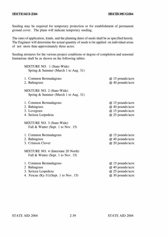
STATE AID 2004 STATE AID 2004
STATE AID 2004 STATE AID 20042-39
SECTION S-214 SECTION S-214
Seeding may be required for temporary protection or for establishment of permanentground cover. The plans will indicate temporary seeding.
The rates of application, kinds, and the planting dates of seeds shall be as specified herein.The Engineer will determine the actual quantity of seeds to be applied on individual areasof not more than approximately three acres.
Seeding mixtures for the various project conditions or degree of completion and seasonallimitations shall be as shown on the following tables:
MIXTURE NO. 1 (State-Wide) Spring & Summer (March 1 to Aug. 31)
1. Common Bermudagrass @ 15 pounds/acre2. Bahiagrass @ 40 pounds/acre
MIXTURE NO. 2 (State-Wide) Spring & Summer (March 1 to Aug. 31)
1. Common Bermudagrass @ 15 pounds/acre2. Bahiagrass @ 40 pounds/acre3. Lovegrass @ 15 pounds/acre4. Sericea Lespedeza @ 25 pounds/acre
MIXTURE NO. 3 (State-Wide) Fall & Winter (Sept. 1 to Nov. 15)
1. Common Bermudagrass @ 15 pounds/acre2. Bahiagrass @ 40 pounds/acre3. Crimson Clover @ 20 pounds/acre
MIXTURE NO. 4 (Interstate 20 North) Fall & Winter (Sept. 1 to Nov. 15)
1. Common Bermudagrass @ 15 pounds/acre2 Bahiagrass @ 40 pounds/acre3. Sericea Lespedeza @ 25 pounds/acre
4. Fescue (Ky-31)(Sept. 1 to Nov. 15) @ 30 pounds/acre

STATE AID 2004 STATE AID 2004
STATE AID 2004 STATE AID 20042-40
SECTION S-214 SECTION S-214
MIXTURE NO. 5 (State-Wide) Winter ( Nov. 16 to Feb. 28)
1. Bahiagrass (Pensacola, Wilmington or Argentine) @ 40 pounds/acre2. Rye Grain (Marshall) @ 20 pounds/acre3. Crimson Clover (Tibbee, Dixie, Autauga, Chief) @ 10 pounds/acre4. Bermuda (unhulled) (Common) @ 25 pounds/acre
USE:
1. Mixture No. 1 and 3 for seasonal vegetation schedule on all pavingprojects.
2. Mixture No. 2 and 4 for seasonal vegetation schedule on grade anddrain projects. In Mixture No. 4, crimson clover will be substituted forfescue (Ky-31) especially south of Interstate 20. Lovegrass and SericeaLespedeza seed specified to be sown in Mixtures 2 and 4 will be sownonly on high fill and backslope areas selected by the Engineer.Mixture No. 5 is intended for use on LSBP projects only or as requiredfor temporary erosion control. This mixture will not be accepted aspermanent erosion control on other projects without the approval of theState Aid Engineer.
3. Legume seeds treated with inoculant must be sown separately fromgrass seed treated with Thiram. The use of separate sowing equipmentis also recommended to prevent germination deterioration of each typeseed.
4. The recommended quantity of fertilizer for all of the above listed seedmixtures is as follows:
800 pounds 10-20-10 per acre600 pounds 13-13-13 per acre200 pounds Ammonium Nitrate per acre
Legume seeds shall be treated in accordance with S-715.03.4 immediately before sowing.Seeds shall be uniformly sown over the entire area with approved mechanical seeders.Seeds of different sizes may necessitate separate sowing. Should legume seeds becomedry, they shall be reinoculated.
Seeding shall not be done during windy weather or when the ground is frozen, extremelywet, or in an untillable condition.
All seeds shall be covered lightly with soil by raking, rolling, or other approved methods,and the area compacted with a cultipacker.

STATE AID 2004 STATE AID 2004
STATE AID 2004 STATE AID 20042-41
SECTION S-214 SECTION S-214
When specified, mulching shall be performed in accordance with the requirements ofS-215 as soon as practicable (no later than twenty-four (24) hours after seeding unlessweather conditions are such that mulch cannot be placed).
S-214.04--Plant Establishment.
S-214.04.1--Plant Establishment and Maintenance. When an area is seeded or topseeded, with or without the addition of mulch, growth or coverage shall be consideredacceptable when a satisfactory stand and growth of in season plantings have sufficientlycovered the area seeded to provide ample erosion protection exclusive of any protectivecover provided by the mulch. It shall be the responsibility of the Contractor that the seedplanted has produced a living and growing vegetative cover at the time of acceptance.
Plant establishment and maintenance shall consist of the necessary protection of theseeded or top seeded areas and other operations of maintenance including watering,weeding, mowing, repairing, and reseeding or all areas damaged or eroded as a result ofthe Contractor's operations, negligence or by normal rains or storms.
Inspection for overall project acceptance will not be made until a minimum period ofthirty (30) days has elapsed after the final planting of seed.
COMPENSATION
S-214.05--Method of Measurement. Seeding, complete and accepted, will be measuredby the acre.
Except as provided under S-107.17, no measurement for payment will be made for anymaterials or work required under S-214.04.
Except for materials and work required under S-214.04, accepted quantities of topsoil,fertilizing, and mulching will be measured as prescribed in the respective sections for suchitems.
Watering for seeding will not be measured for separate payment.
S-214.06--Basis of Payment. Seeding, measured as prescribed in S-214.05, will bepaid for at the contract unit price bid per acre which shall be full compensation forcompleting the work specified.
Payment will be made under:
S-214-A: Seeding - per acre
STATE AID 2004 STATE AID 2004
STATE AID 2004 STATE AID 20042-42
SECTION S-215 - MULCHING
S-215.01--Description. This work shall consist of furnishing, transporting, placing, andanchoring vegetative mulch on slopes, shoulders, and other areas indicated on the plans,or designated.
MATERIALS
S-215.02--Material Requirements. The vegetative materials for mulch shall meet therequirements of S-715.05.
It is intended that Type I Vegetative Materials shall be used when available. When it isdetermined by the Engineer with the concurrence of the State Aid Engineer that Type IVegetative Material is not reasonably available, Type II Vegetative material will bepermitted as provided in S-715.05.
Bituminous material for mulch shall be Emulsified Asphalt, Grade SS-1, meeting therequirements of S-702.07.
S-215.03--Equipment. Mulching equipment shall be capable of maintaining a constantair stream which will blow or eject controlled quantities of mulch in a uniform pattern.If asphalt is used, a jet or spray nozzle for applying uniform, controlled amounts ofasphalt to the vegetative material as it is ejected shall be located at or near the dischargespout.
Mulch stabilizers shall consist of dull blades or disks without camber and approximately20 inches in diameter. The disks shall be notched, shall be spaced at approximately 8inches and shall be equipped with scrapers. The stabilizer weight shall be approximately1000 - 1100 pounds, shall have a working width of no more than 8 feet, and shall beequipped with a ballast compartment so that, when directed, weight can be increased.
CONSTRUCTION REQUIREMENTS
S-215.04--Construction Details.
S-215.04.1--Placement of Vegetative Mulch. Mulching shall be placed uniformly ondesignated areas within 24 hours following seeding unless weather conditions are such thatmulching cannot be performed. Placement shall begin on the windward side of areas andfrom tops of slopes. In its final position the mulch shall be loose enough to allow air tocirculate but compact enough to partially shade the ground and reduce erosion.
STATE AID 2004 STATE AID 2004
STATE AID 2004 STATE AID 20042-43
SECTION S-215 SECTION S-215
The baled material shall be loosened and broken thoroughly before it is fed into themachine to avoid placement of unbroken clumps.
S-215.04.2--Rates of Application and Anchoring Mulch. The Engineer will designatethe rate of application of vegetative mulch within the limits of one (1) to three (3) tonsper acre. The mulch shall be anchored by either the use of a mulch stabilizer or bytacking with bituminous material as directed by the Engineer. If bituminous material isused, the rate of application shall be 90 to 150 gallons per ton of vegetative material.If a mulch stabilizer is used, the mulch shall be punched into the soil for a minimumdepth of 1 inch.
Where steep slopes or soil conditions are such that anchoring cannot be performedsatisfactory with a mulch stabilizer the Engineer will require that bituminous material beapplied at the time or immediately following the mulch placement. When mulchstabilizers are used, anchoring the mulch shall be performed along the contour of theground surface. As the work progresses, the Engineer will determine the actual rate ofapplication of the vegetative mulch and the bituminous material (if used) on each area notto exceed three acres. For vegetative mulch, a tolerance of fifteen (15) percent will bepermitted without correction. For bituminous material (if used), a tolerance of ten (10)percent will be permitted without correction. Areas deficient in application by more thanthese amounts shall be corrected by reapplication in a manner approved by the Engineer.For areas on which vegetative material has been placed in excess of the tolerancepermitted, that portion of the material placed in excess of the tolerance allowed will bededucted from the measured quantities. In the event an excess of vegetative material hasbeen placed in a quantity deemed by the Engineer to be undesirable, the Contractor shallremove and replace all material placed on that area at no additional cost to the project.
S-215.05--Protection and Maintenance. The Contractor shall maintain and protectmulched areas until final acceptance of the project. He shall take every precaution toprevent unnecessary foot and vehicular traffic and shall repair and restore immediately anydisplacement of mulch without extra compensation.
At appropriate times determined by the Engineer, the Contractor shall mow or otherwiseremove or destroy all undesirable growth on all areas mulched to prevent competition withthe desired plants and to prevent reseeding of undesirable growth. All mowing shall bea part of protection and maintenance.

STATE AID 2004 STATE AID 2004
STATE AID 2004 STATE AID 20042-44
SECTION S-215 SECTION S-215
COMPENSATION
S-215.06--Method of Measurement. Accepted quantities of vegetative material formulch will be measured in tons of 2000 pounds.
The weight for measurement will be the product of the number of bales acceptably placedand the average weight per bale as determined on approved scales provided by theContractor.
Anchoring of vegetative mulch, whether by use of a mulch stabilizer or by application ofbituminous material, will not be measured for separate payment unless provided for in theplans or in accordance with S-104-02.
Asphalt emulsion, when included as a pay item, will be measured in gallons.
S-215.07--Basis of Payment. Vegetative material for mulch will be paid for at thecontract unit price per ton, which shall be full compensation for completing the workspecified. Asphalt emulsion will be measured in gallons.
Payment will be made under:
S-215-A: Vegetative Materials for Mulch - per ton
S-215-B: Mulch, Asphalt Emulsion - per gallon
Sections S-216 thru S-225 - Blank.

STATE AID 2004 STATE AID 2004
STATE AID 2004 STATE AID 20042-45
SECTION S-226 - SOLID SODDING
S-226.01--Description. This work shall consist of furnishing, transporting, and plantingapproved grass sod in accordance with the plans and these specifications. This work shallalso include plant establishment as specified and required to assure satisfactory growth ofthe solid sod.
MATERIALS
S-226.02--Material Requirements. Unless otherwise specified, solid sod shall bebermuda (common), bahia, or other approved sod species and shall be live, fresh,growing grass with at least one and one-half inches of soil adhering firmly to the rootswhen placed. The sod shall be reasonably free from obnoxious weeds or other grasses,and shall not contain any matter deleterious to its growth, or which might affect itssubsistence or hardiness when transplanted. The sod shall be in strips or blocks at leasteight inches by eight inches and reasonably free from ragged edges.
All sod shall be harvested from areas where the topsoil is fertile, and the areas shall havebeen grazed or mowed sufficiently to form a dense turf. After approval, the area fromwhich the solid sod is to be harvested shall be closely mowed and raked, if deemednecessary, to remove excessive top growth and debris.
When specified, the solid sod material shall be the kind specified, nursery grown, healthy,free from damage, and free from obnoxious weeds and grasses. The nursery grown sodshall be in blocks at least eight inches by eight inches by one inch and reasonably free ofragged edges.
All solid sod materials shall be approved by the Engineer prior to transplanting.
Fertilizer used in the construction shall be in accordance with S-212.
CONSTRUCTION REQUIREMENTS
S-226.03--Construction Details.
S-226.03.1--Procuring and Handling Sod. Approved sod cutters shall be used forcutting the sod into strips or blocks. Care shall be exercised at all times to retain thenative soil on the roots of the sod during the process of excavating, hauling, and planting.
The sod shall be transplanted within twenty-four (24) hours after arriving on the project,unless it is stacked in a manner satisfactory to the Engineer. All sod in stacks shall bekept moist and protected from exposure to the wind and sun and from freezing. In noevent shall more than three days elapse between the cutting and planting of the sod withoutapproval of the Engineer.
STATE AID 2004 STATE AID 2004
STATE AID 2004 STATE AID 20042-46
SECTION S-226 SECTION S-226
S-226.03.2--Grading of the Area to Receive Solid Sodding. Prior to ground preparationfor solid sodding, all excavating, shaping, and dressing shall have been completed in sucha manner that the foundation for the sod has the proper cross section, line, and grade andso that the sod after placement will be flush with or slightly below the adjacent finalground line.
S-226.03.3--Ground Preparation and Fertilizing. After the area has been graded asrequired, the specified types and quantities of fertilizers shall be uniformly spread andthen incorporated by standard ground preparation in accordance with S-212. The pre-pared area shall be at an approved moisture content and shall present a smooth, uniformsurface with reasonably close conformity to the specified line, grade, and cross section.After approval by the Engineer of the prepared and fertilized area, sodding shall followimmediately.
S-226.03.4--Planting Sod. The sod shall be placed on the prepared surface with edgesin close contact and starting at the lowest point and working upward. Cracks betweenblocks of sod shall be filled with small pieces of fresh sod, and all cracks too small forsod shall be filled by a light dressing of approved soil. The entire sodded area shall thenbe compacted and watered to the satisfaction of the Engineer. Light rollers, hand tamps,or other approved equipment shall be used for compacting.
On areas which the Engineer deems that the sodding might slide due to the height andslope of the surface or nature of the soil, the sod shall be "pegged" with wooden pegsdriven through the sod blocks into firm earth. Pegs shall be at intervals deemed suitableto hold the sod in place.
S-226.03.5--Limitations. Solid sodding shall be performed only when weather and soilconditions are deemed by the Engineer to be suitable for proper placement.
S-226.04--Plant Establishment. Plant establishment shall consist of preserving,protecting, replacing, watering, mowing, and other work necessary to keep the sod ina satisfactory condition at all times until final acceptance.
A satisfactory growth of solid sodding shall be understood to mean a healthy, living, andgrowing grass turf which has been planted on an approved prepared foundation and hasbeen maintained in accordance with the requirements of these specifications.
STATE AID 2004 STATE AID 2004
STATE AID 2004 STATE AID 20042-47
SECTION S-226 SECTION S-226
COMPENSATION
S-226.05--Method of Measurement. Solid sodding, complete in place and accepted, willbe measured by the square yard.
If solid sodding is required by the contract, or ordered by the Engineer, on a sectiongraded under a previous contract, required excavation, exclusive of trenching out and finegrading, will be measured under the appropriate excavation item of the contract, or asExtra Work.
Fertilizer ordered and acceptably used will be measured and paid for as prescribed inS-212.
S-226.06--Basis of Payment. Solid sodding will be paid for at the contract unit price persquare yard which shall be full compensation for completing the work specified.
Payment will be made under:
S-226-A: Solid Sodding - per square yard
STATE AID 2004 STATE AID 2004
STATE AID 2004 STATE AID 20042-48
SECTION S-227 - EXCELSIOR BLANKET
S-227.01--Description. This work shall consist of furnishing, placing, and maintainingexcelsior blanket on seeded, or other designated areas in accordance with the requirementsshown on the plans and these specifications.
MATERIALS
S-227.02--Material Requirements. The excelsior blanket shall meet the requirementsof S-715.09.2.
CONSTRUCTION REQUIREMENTS
S-227.03--Construction Details. The area to be covered shall be prepared, fertilized, andvegetated before the blankets are placed. Immediately following the planting operations,the blankets shall be laid evenly, smoothly, and in contact with the soil throughout andwith the fabric net on top of the blankets. Asphalt-coated mulch should be omitted fromall areas receiving the excelsior blanket.
In ditches, the blankets shall be unrolled in the direction of water flow. When two ormore strips are required to cover a ditch area, they shall overlap a minimum of fourinches with the upgrade width on top. In case a strip is spliced lengthwise, the edges ofthe strips shall overlap a minimum of six inches with the upgrade section on top.
When used on slopes, the blankets may be placed either horizontally or vertically on theslope with the edges and ends of adjacent strips butted tightly against each other.
Each strip shall be stapled in three rows (each edge and center with the center rowalternately spaced) with staples spaced not more than four feet longitudinally. When usingtwo or more strips side by side on slopes, a common row of staples shall be used on theadjoining strips to secure the outside netting strand of each strip. Ends of strips shall bestapled at one foot intervals. Staples shall be firmly embedded in the underlying soil.
S-227.04--Protection and Maintenance. The Contractor shall maintain and protect theexcelsior blankets until final acceptance or until the Engineer has determined that theblanket has served its useful life, whichever occurs first. Maintenance shall consist ofrepairs necessitated by erosion, wind, fire, or other cause.
STATE AID 2004 STATE AID 2004
STATE AID 2004 STATE AID 20042-49
SECTION S-227 SECTION S-227
COMPENSATION
S-227.05--Method of Measurement. Excelsior blanket, installed as specified, completein place, and accepted, will be measured by the square yard of surface area covered.
S-227.06--Basis of Payment. Excelsior blanket will be paid for at the contract unit priceper square yard, which shall be full compensation for completing the work specified.
Payment will be made under:
S-227-A: Excelsior Blanket - per square yard
Section S-228 - Blank.
STATE AID 2004 STATE AID 2004
STATE AID 2004 STATE AID 20042-50
SECTION S-229 - PAVED DITCHES
S-229.01--Description. This work shall consist of constructing paved ditches ofportland cement concrete, as specified in the contract, constructed in accordance with theprovisions and requirements of these specifications, and in reasonably close conformitywith the lines, grades, typical cross sections, and locations shown on the plans orestablished by the Engineer.
MATERIALS
S-229.02--Material Requirements.
S-229.02.1--Portland Cement Concrete Paved Ditches. The materials used in theconstruction of portland cement concrete paved ditches shall conform to the applicableprovisions and requirements of S-804.
S-229.02.2--Reinforcement. Reinforcement shall meet the requirements of S-711.
CONSTRUCTION REQUIREMENTS
S-229.03--Construction Details.
S-229.03.1--General. The foundation for paved ditches shall be formed by excavatingto the required depth and dimensions below the prepared finished surface grade of thepaved ditch.
The foundation shall be thoroughly compacted by hand tamping or other approvedmethod. Soft, spongy, or other unsuitable material shall be removed as directed, andreplaced with suitable material thoroughly compacted in six inch layers.
The forms used in this construction may be wood or metal; shall have a depth equal to theprescribed edge thickness of the paved ditch; and shall be of sufficient strength towithstand the weight of the concrete and the pressure incidental to vibration or compactionwithout bulging or displacement. Forms shall be securely staked and braced.
Reinforcement, if specified, shall be placed in a manner that will insure its proper positionin the paved ditch section after all concrete is placed.
S-229.03.2--Portland Cement Concrete Paved Ditches. Unless otherwise specified onthe plans, the portland cement concrete paved ditches shall be constructed of Class "C"concrete, mixed and placed in accordance with the applicable requirements of S-804, andcured in accordance with the requirements of S-804 or by other approved methods. Thelimitations of mixing, placing, and curing shall conform to the requirements of S-804.
STATE AID 2004 STATE AID 2004
STATE AID 2004 STATE AID 20042-51
SECTION S-229 SECTION S-229
A template mounted on the side forms shall be used in striking off and finishing thesurface of the concrete to the required shape and dimensions. The entire unit shall beconstructed monolithic with smooth fillets or curves at all angles or breaks in flow lines.Concrete shall be placed beginning at the bottom of the slope and progressing upward.The finished surface shall be given a Class 6, Floated Surface Finish in conformity withthe requirements of S-804.03.19.5.
Expansion joints shall be constructed at the locations indicated on the plans or as directed,and shall be of the specified materials and dimensions.
S-229.03.3--Backfilling and Cleaning Up. After the concrete has set sufficiently, theforms shall be removed and the spaces around the paved ditch shall be backfilled withapproved material and thoroughly compacted without damage to the paved ditch. Theadjacent ditch slopes shall be neatly trimmed to the required section, and all surplusmaterial disposed of as directed.
COMPENSATION
S-229.04--Method of Measurement. The completed and accepted portland cementconcrete paved ditch will be measured in cubic yards.
Excavation required for trenching and fine grading will not be measured for separatepayment.
Other required excavation will be measured for payment under the applicable excavationitems.
S-229.05--Basis of Payment. Portland cement concrete paved ditch will be paid for atthe contract unit price per cubic yard, which shall be full compensation for completing thework specified.
Payment will be made under:
S-229-A: Portland Cement Concrete Paved Ditch - per cubic yard
STATE AID 2004 STATE AID 2004
STATE AID 2004 STATE AID 20042-52
SECTION S-230 - BITUMINOUS TREATED ROVING
S-230.01--Description. This work consists of furnishing and installing a layer ofbituminous treated roving to stabilize newly planted soil areas in ditches and on slopes inaccordance with these specifications and at locations shown on the plans or as directed bythe Engineer.
S-230.02--Materials.
S-230.02.1--General. The type of roving material (fiberglass or polypropylene) shall beat the option of the Contractor unless otherwise specified and shall meet the applicablerequirements of S-715.09.6.
The glass fibers or fibrillated polypropylene yarn shall be wound onto cylindricalpackages so that the roving can be continuously fed through an ejector driven bycompressed air and expanded into a mat. The fibers or yarn shall be lightly boundtogether in a ribbon form, without the use of clay, starch, or other deleterious substances.The material shall not contain petroleum solvents, or other agents known to be toxic toplant or animal life.
The roving material shall not be exposed to moisture prior to placement.
S-230.02.2--Bituminous Material. The bituminous material used for securing theroving to the existing soil shall be Emulsified Asphalt, Grade SS-1, meeting therequirements of S-702.07.
S-230.03--Construction Requirements.
S-230.03.1--Equipment. An air compressor shall be used in conjunction with applyingthe glass fiber or polypropylene yarn. A compressor capable of supplying forty (40)cubic feet per minute at 80 to 100 pounds per square inch is required. One air gunspecifically designed for spraying glass fibers or polypropylene yarn, sufficientthree-eights inch diameter rubber hose for application, and at least one bucket containershall be furnished for applying the material. Three spools or packages may be runsimultaneously from a 125 cubic foot compressor. Equipment which cuts or breaks theroving will not be permitted. Equipment for applying the asphalt shall be capable ofapplying the material in a uniform spray at the rate specified.
S-230.03.2--General. The bituminous treated roving shall be applied over designatedareas within 24 hours following the planting or seeding operations. The designated areasshall be free of all objects including the vegetative material for mulch that would keep theroving material from being in direct contact with soil throughout the entire area to betreated.
The upgrade and downgrade ends of the bituminous treated roving shall be buried in a sixinch minimum vertical slot and the soil tamped firmly against it.
STATE AID 2004 STATE AID 2004
STATE AID 2004 STATE AID 20042-53
SECTION S-230 SECTION S-230
The bituminous treated roving shall be applied uniformly over the planted areas at thefollowing rate:
a) Bituminous Treated Fiberglass Roving: 0.50 pounds (+ 20%) persquare yard; or
b) Bituminous Treated Polypropylene Roving: 0.20 pounds (+ 20%) persquare yard.
The rate of distribution will be determined from the number of spools or packages ofroving used on each area and the average weight of the spools or packages. A sample ofat least five spools or packages designated at random by the Engineer will be taken andweighed and the average weight to the nearest pound per spool or package will be usedfor the truckload from which the sample was taken.
Immediately following the spreading of roving, the asphaltic material shall be applieduniformly over the roving at the rate of 0.50 gallons (+ 20%) per square yard.
The Contractor shall be required to apply additional asphaltic material, if needed, topenetrate through the roving in sufficient quantity to secure the roving to the soil.
S-230.03.3--Protection and Maintenance. The Contractor shall maintain and protect thebituminous treated roving mat until release of maintenance or until the Engineer hasdetermined that the mat has served its useful life, whichever occurs first. Maintenanceshall consist of repairs made necessary by erosion, wind, fire, or any other cause.
S-230.04--Method of Measurement. Bituminous treated roving installed as specified,complete in place and accepted, will be measured by the square yard of surface areacovered.
The additional materials required for terminal slots and materials placed outside the limitsof the designated area(s) requiring treatment will not be measured for payment.
S-230.05--Basis of Payment. Bituminous treated roving measured as prescribed abovewill be paid for at the contract unit price per square yard, which shall be fullcompensation for completing the work.
Payment will be under:
S-230-A: Bituminous Treated Roving - per square yard
STATE AID 2004 STATE AID 2004
STATE AID 2004 STATE AID 20042-54
SECTION S-231 - EROSION CONTROL FABRIC
S-231.01--Description. This work shall consist of furnishing, placing, and maintainingerosion control fabric on seeded or other designated areas in accordance with therequirements of the plans and these specifications.
MATERIALS
S-231.02--Materials. The erosion control fabric shall consist of a flexible knittedconstruction of high strength degradable yarn with uniform openings interwoven withstrips of biodegradable paper and meeting the following requirements:
Width - 48 inch minimumWeight - 0.2 pounds per square yard (approximate)
Staples for securing the fabric in place shall be "U" shaped, made from eleven (11) gageor heavier steel wire, have a width one to two inches at the throat, and be a minimum ofsix inches from top to bottom after bending.
For erosion control fabric, the Contractor shall forward to the Engineer three copies ofthe manufacturer's certification for each shipment of the fabric stating the number of rollsfurnished, and that the material complies with the requirements of the specifications.
For staples, the Contractor shall forward to the Engineer three copies of themanufacturer's or distributor's certification showing the wire size for each shipment ofstaples.
The certifications by the manufacturer or distributor will be prima facie evidence of thematerials meeting the above requirements. All erosion control fabric and staples will,however, be subject to approval by the Engineer.
CONSTRUCTION REQUIREMENTS
S-231.03--Construction Requirements. The areas to be covered shall be prepared,fertilized, and vegetated as specified before the fabric is installed. The mulch materialshall be omitted from areas receiving the fabric. Immediately following the plantingoperation, the fabric shall be installed by unrolling it in the direction of water flow anddraping it loosely, without folds or stretching, so that continuous ground contact ismaintained. The ends of the fabric at the beginning and end of each area to be coveredshall be folded and placed in an anchor trench at least four inches deep, and stapled in thetrench on approximately twelve (12) inch centers, backfilled, and tamped.

STATE AID 2004 STATE AID 2004
STATE AID 2004 STATE AID 20042-55
SECTION S-231 SECTION S-231
When two or more strips are required to cover an area, they shall overlap a minimum offour inches. In case a strip is to be spliced lengthwise, the edges of the strips shalloverlap a minimum of six inches with the upgrade section on top. Each strip shall bestapled in three rows (each edge and center with center row alternately spaced) withstaples spaced not more than four feet longitudinally. The ends of all strips splicedlengthwise shall be stapled at one foot intervals across the entire width of the fabric.
Where heavy concentrations of water or extremely erodible soil conditions exist, erosionchecks shall be installed at 50 foot intervals as directed by the Engineer. Erosionchecks shall be a row of staples 12 inches on center across the width of the fabricperpendicular to the flow line.
All staples shall be firmly embedded in the underlying soil.
S-231.04--Protection and Maintenance. The Contractor shall maintain and protect theerosion control fabric until final acceptance or until the Engineer has determined that thefabric has served its useful life, whichever occurs first. Maintenance shall consist ofrepairs made necessary by erosion, wind, fire or any other cause.
COMPENSATION
S-231.05--Method of Measurement. Erosion control fabric installed as specified,complete in place, and accepted will be measured by the square yard of surface areacovered.
The additional fabric material required for overlaps, anchor slots, and over-width of stripswill not be measured for payment.
S-231.06--Basis of Payment. This work measured as prescribed above will be paid forat the contract unit price per square yard, which shall be full compensation for completingthe work specified.
Payment will be made under:
S-231-A: Erosion Control Fabric - per square yard

STATE AID 2004 STATE AID 2004
STATE AID 2004 STATE AID 20042-56
SECTION S-232 - GEOTEXTILE FABRIC STABILIZATION
S-232.01--Description. This work consists of furnishing and installing geotextile fabricfor stabilization of embankments and subgrades as shown in the plans and in conformancewith these specifications.
S-232.02--Material. The fabric and incidental materials for this work shall meet therequirements of S-714.13.
S-232.03--Construction Details. A subgrade which is to receive geotextile fabric shallbe shaped and compacted to a smooth finish and free of loose material and sharp objects.An embankment site shall be cleared and graded to establish a relatively smooth surface.Trees and stumps are to be cut off at ground line and sawdust or sand placed over theseareas to provide a cushion for the fabric.
The fabric shall be placed as smooth as possible and free from tension, stress, folds,wrinkles or creases.
Where more than one layer of fabric is required, all joints of the bottom layer shall besewn to develop the required fabric strength perpendicular to the joint. The top layer andsingle layer installations of fabric may be overlapped a minimum of two feet at each jointor sewn.
Fabrics which weigh less than eight ounces per square yard shall be factory or field sewnwith a "J" type seam. Heavier weight fabrics shall be factory sewn with two parallel bagtype seams approximately one-fourth inch apart or field sewn with an additional seamzigzagged across the two parallel seams.
Securing pins with washers shall be inserted along a line through the midpoint of anyoverlap or sewn seam at intervals required by the Engineer to prevent movement of thefabric until covered.
The subsequent course of material shall be back-dumped in such a manner as to avoiddamage to the underlying fabric. No equipment will be allowed to operate over the fabricuntil it is covered with a layer of material of sufficient thickness to protect the fabricinstallation. When the underlying soil is very unstable, the two outer one-third portionsof an embankment layer shall be placed approximately 25 feet in advance of the centerone-third portion to prevent excessive mudwave movements and damage to the fabricinstallation.
The Contractor shall provide equipment necessary for placing the fabric in the positionand location as detailed on the plans.

STATE AID 2004 STATE AID 2004
STATE AID 2004 STATE AID 20042-57
SECTION S-232 SECTION S-232
S-232.04--Method of Measurement. Fabric placed in accordance with thesespecifications and as directed by the Engineer will be measured by the square yard ofsurface area covered. Any overwidth of material installed and additional material requiredfor laps or sewing will not be measured.
S-232.05--Basis of Payment. The accepted quantities of fabric will be paid for at thecontract unit price per square yard. This payment will be full compensation forfurnishing and placing the fabric, pins, lapping, sewing, maintaining the fabric untilcovered, and satisfactorily completing the work.
Payment will be made under:
No. S-232-A: Geotextile Fabric Stabilization (Type ) (AOS * ) - per square yard
* When not designated, see S-714.13.
STATE AID 2004 STATE AID 2004
STATE AID 2004 STATE AID 20042-58
SECTION S-233 - TEMPORARY SILT FENCE
S-233.01--Description. This work shall consist of furnishing, constructing, maintaining,and removing a water permeable filter type of fence for the purpose of removingsuspended soil particles from the water passing through it in accordance with therequirements shown on the plans and these specifications.
The quantity of temporary silt fence to be installed will be affected by the actualconditions which occur during the construction of the project.
It is understood that measurement and payment for temporary silt fence will be made onlywhen ordered, and a pay item is included in the bid schedule of the proposal. Thequantities for temporary silt fences, when shown in the contract, are estimated forbidding purposes only, and these quantities may be varied dependent upon actual needsfor the specific purpose designated.
MATERIALS
S-233.02--Material Requirements. The fabric and incidental materials for this workshall meet the requirements of S-714.13.
S-233.02.1--Posts. Either wood or steel posts may be used. Wood posts shall bestraight enough to provide a fence without noticeable misalignment. Steel posts shall haveprojections for fastening the wire to the fence.
S-233.02.2--Filter Fabric. The filter fabric shall be composed of strong rot-proofsynthetic fibers formed into a fabric of either the woven or unwoven type. Either typeof fabric shall be free of any treatment or coating which might significantly alter itsphysical properties after installation. The fabric shall contain stabilizers and/or inhibitorsto make the filaments resistant to deterioration resulting from exposure to sunlight or heat.The fabric shall be a pervious sheet of synthetic fibers oriented into a stable network sothat the fibers retain their relative position with respect to each other.
The edges of the fabric shall be finished to prevent the outer yarn from pulling away fromthe fabric. The fabric shall be free of defects or flaws which significantly affect itsphysical and/or filtering properties. Sheets of fabric may be sewn or bonded together.No deviation from any physical requirements will be permitted due to the presence of theseam.
During all periods of shipment and storage, the fabric shall be wrapped in a heavy dutyprotective covering which will protect the cloth from sunlight, mud, dust, dirt and debris.The fabric shall not be exposed to temperatures greater than 140oF.
STATE AID 2004 STATE AID 2004
STATE AID 2004 STATE AID 20042-59
SECTION S-233 SECTION S-233
S-233.02.3--Identification. Each roll of fabric or container shall be visibly labeled withthe name of the manufacturer, type of fabric or trade name, lot number and quantity ofmaterial.
S-233.02.4--Certification. The Contractor shall furnish to the Engineer three copies ofthe Manufacturer's certified test report(s) showing results of all required tests andcertification that the material meets the specifications. Also forward three copies of themanufacturer's or distributor's certification showing the wire size for each shipment ofstaples.
CONSTRUCTION REQUIREMENTS
S-233.03--General. Silt fences shall be constructed at the locations shown on the plansor as directed by the Engineer.
All posts shall be installed so that no more than three feet of the post protrude above theground. Extra post for bracing shall be installed as directed by the Engineer. The wovenwire shall be securely fastened to the wood posts with staples. When metal posts areused, the wire shall be fastened to the posts with wire or other approved means. Thefabric shall be attached to the wire fence with wire or other approved means. The bottomedge of the fabric shall be buried 6 inches below ground surface to prevent undermining.When splicing of the fabric is necessary, two posts shall be installed approximately 18inches apart and each piece of fabric shall be fastened to both posts.
At the time of or during installation, the fabric will be rejected if it has defects, rips,holes, flaws, deterioration or damage incurred during manufacturing, transporting, storageor installation.
Fabric meeting the requirements of Type II may be installed without the woven wire fencebacking, provided:
A. Post spacing is reduced to six feet or less.
B. The fabric has been approved by the Engineer, and the manufacturerrecommends its use without the woven wire fence backing.
C. Fence posts shall be inclined toward the runoff source at an angle ofnot more than 20o from vertical.
D. Fabric shall be attached to the posts as recommended by themanufacturer.
STATE AID 2004 STATE AID 2004
STATE AID 2004 STATE AID 20042-60
SECTION S-233 SECTION S-233
S-233.04--Maintenance and Removal. The Contractor shall maintain the silt fence andshall remove and replace when deteriorated to such extent that it is no longer effective.The Contractor shall remove accumulated siltation when sediment reaches one half thefence height.
Unless otherwise specified, all silt fences shall be removed. Upon removal, theContractor shall remove and dispose of excess silt accumulations, dress the area to givea pleasing appearance and vegetate all bare areas in accordance with contractrequirements. The fence materials will remain the property of the Contractor and maybe used at other locations provided the materials are acceptable to the Engineer.
COMPENSATION
S-233.05--Method of Measurement. Temporary silt fence, complete in place andacceptable will be measured by the linear foot.
S-233.06--Basis of Payment. Temporary silt fence will be paid for at the contract unitprice per linear foot which shall be full compensation for completing the work specified.
Payment will be made under:
S-233-A: Temporary Silt Fence (Type ) (AOS * ) - per linear foot
* When not designated, see S-714.13.
Section S-234 - Blank.
STATE AID 2004 STATE AID 2004
STATE AID 2004 STATE AID 20042-61
SECTION S-235 - TEMPORARY EROSION CHECKS
S-235.01--Description. This work consists of furnishing, constructing and maintainingbaled hay or straw erosion checks for the retention of soil along the toe of fill slopes,around inlets, swale areas, small ditches, sediment basins and other areas as directed bythe Engineer in accordance with the requirements shown on the plans and thesespecifications. Also, the work includes removing and disposing of the erosion checks andsilt accumulations as directed by the Engineer.
Measurement and payment for temporary erosion checks will be made only when orderedand a pay item is included in the bid schedule of the proposal. The quantity is estimatedfor bidding purposes only and will be dependent upon actual conditions which occurduring construction of the project.
S-235.02--Materials. Approved baled hay or straw material (Type I or II) shall berectangular in shape with a minimum length of 32 inches and shall meet the requirementsof S- 715.05. The wooden stakes used in securing the baled material in place shall beapproximately 2" x 2" x 34" meeting the approval of the Engineer.
S-235.03--Construction Requirements.
S-235.03.1--General. The erosion checks shall be constructed at the locations andaccording to the requirements shown on the plans or as directed by the Engineer. Erosionchecks required along the toe of fill slopes shall be constructed prior to grading operationsat the site. For other locations, the erosion checks shall be constructed when directed bythe Engineer.
The soil shall be excavated at least three inches in depth to embed the baled material.After securing in place, a sufficient quantity of the excavated material shall be placedaround the erosion check and compacted to prevent undermining.
S-235.03.2--Maintenance and Removal. The Contractor shall maintain the erosionchecks and remove and dispose of silt accumulations that reach 1/2 the bale height or asdirected by the Engineer. When the erosion checks are no longer needed, they shall beremoved; and the Contractor shall dispose of silt accumulations and treat the disturbedareas in accordance with the contract requirements.
S-235.04--Method of Measurement. Erosion checks, complete in place and accepted,will be measured by actual count of the total bales used in constructing, replacing andmaintaining the erosion checks.
S-235.05--Basis of Payment. Erosion checks will be paid for at the contract unit priceper bale and which shall be full compensation for completing, maintaining and removalof the erosion checks and the removal and disposal of silt accumulations.
Payment will be made under:
S-235-A: Temporary Erosion Checks - per bale
STATE AID 2004 STATE AID 2004
STATE AID 2004 STATE AID 20042-62
SECTION S-236 - TEMPORARY SILT BASINS
S-236.01--Description. This work consists of excavation and satisfactory disposal of allmaterials excavated in the construction, clean out, and maintenance of silt basins. Thiswork may also consist of maintenance and removal of existing silt basin constructed onprevious projects.
The Contractor shall construct earth dikes and overflow spillways, furnish and installoutfall pipe, perforated elbows, perforated risers, and trash racks in silt basins whereshown on the plans or as directed by the Engineer. The quantity of silt basins to beplaced will be affected by the actual conditions which occur during the construction of theproject.
It is understood that measurement and payment for silt basins will be made only whenshown on the plans or ordered by the Engineer, and a pay item is included in the bidschedule of the proposal. The quantity is estimated for bidding purposes only and will bedependent upon actual needs during construction of the project.
S-236.02--Blank.
S-236.03--Construction Requirements.
S-236.03.1--General. The Contractor shall excavate silt basins to the dimensions and atthe locations shown on the plans or as directed by the Engineer. The silt basins, new orexisting, shall be cleaned out as frequently as necessary to have at least 50% of the basincapacity available at all times. The silt basins shall be completely cleaned out and theslopes shaped and dressed for seeding and mulching prior to completion of the projectunless otherwise directed by the Engineer. Grassing shall be done in accordance with theprovisions contained in the contract for the roadway and will not be measured as aseparate item.
S-236.03.2--Maintenance and Removal. The silt basins shall be maintained so they willfunction properly until the Contractor is released from maintenance, all as determined bythe Engineer.
All excavated materials shall be utilized in the construction of the basin or roadwayembankments except where otherwise directed by the Engineer. Materials not used shallbe disposed of as directed by the Engineer.
Upon removal of a silt basin, the pipe, elbows, risers and trash racks may be used at otherlocations provided they are in condition acceptable to the Engineer. Pipe, elbows, risersand trash racks will remain the property of the Contractor upon completion of the project.
STATE AID 2004 STATE AID 2004
STATE AID 2004 STATE AID 20042-63
SECTION S-236 SECTION S-236
S-236.04--Method of Measurement. Silt basin, complete in place and accepted, will bemeasured per each. Once a silt basin has been constructed, it shall be paid for at the unitprice per each; however clean outs or maintenance will need to be performed on that siltbasin throughout the length of the project. No additional compensation will be allowedfor additional clean outs, maintenance, or removal at the completion of the project.
Maintenance and removal of existing silt basin will be measured per each. Once anexisting silt basin has been cleaned out, it shall be paid for at the unit price per each;however additional clean outs or maintenance may need to be performed on that silt basinthroughout the length of the project. No additional compensation will be allowed foradditional clean outs, maintenance, or removal at the completion of the project.
S-236.05--Basis of Payment. Silt basin will be paid for at the contract unit price per eachwhich shall be full compensation for construction, maintaining, removal, grassing and anyother work required to make the basin function. Maintenance and removal of existing siltbasin will be paid for at the contract unit price per each which shall be full compensationfor maintaining, removal, grassing and any other work required to make the basinfunction.
Payment will be made under:
S-236-A: Silt Basin ( Type * ) - per each
S-236-B: Maintenance and Removal of Existing Silt Basin - per each
* Refer to MDOT Roadway Design Standard Drawings for Type.
Sections S-237 and S-238 - Blank.
STATE AID 2004 STATE AID 2004
STATE AID 2004 STATE AID 20042-64
SECTION S-239 - TEMPORARY SLOPE DRAINS
S-239.01--Description. This work consists of furnishing materials for, constructing andmaintaining temporary slope drains, to include berms, pipe and riprap, as directed by theEngineer in accordance with the requirements shown on the plans and these specificationsto control soil erosion and water pollution. Also, the work includes removing anddisposing of the temporary slope drains.
This temporary erosion control provision shall be coordinated with the permanent erosioncontrol features to assure economical, effective and continuous erosion control throughoutthe construction period.
Measurement and payment for temporary slope drains will be made only when a pay itemis included in the bid schedule of the proposal. The quantity is estimated for biddingpurposes only and may vary depending upon actual construction requirements.
S-239.02--Materials. The temporary shoulder berm may be constructed fromembankment material.
The temporary pipe shall be 8-inch minimum diameter and leak proof.
The temporary riprap shall be hard, durable stones or broken concrete, angular in shapeand shall be of sufficient size to prevent scour where installed.
S-239.03--Construction Requirements. Temporary slope drains shall be constructed atthe intervals and locations designated or deemed appropriate by the Contractor andapproved by the Engineer for channeling runoff waters down embankment slopes andaccording to the requirements shown on the plans.
Slope drains shall be adequately anchored to the slopes and their outlets constructed orplaced to prevent erosion.
Berms may be constructed from embankment material using the heel of a motor graderblade, bulldozer blade or other approved equipment and compacted using the wheels ortracks of same equipment.
Riprap shall be placed in accordance with the plans where the pipe outlet location issubject to scour. The riprap may be end dumped.
Pipe shall be placed in accordance with the plans and extended as required to coincidewith the height of embankment by the end of each work day.
STATE AID 2004 STATE AID 2004
STATE AID 2004 STATE AID 20042-65
SECTION S-239 SECTION S-239
Prior to the suspension of grading operations each day, the Contractor shall shape theearthwork in a manner that will direct storm water runoff to the temporary slope draininstallations.
The temporary slope drains shall be operated and maintained by the Contractor in anacceptable functional condition until the slopes are protected with permanent erosioncontrol measures.
When the temporary erosion and pollution control installations are no longer required, theContractor shall remove and dispose of all materials and restore the areas by establishinggrowth and coverage of vegetative items as required for the remainder of the project.
S-239.04--Method of Measurement. Temporary slope drains will be measured by thelinear foot of temporary pipe, which includes berms, riprap, and pipe including elbowsor special sections. Measurement shall be along the line and grade of the pipe installationfrom end to end along the centerline of the pipe installed and accepted.
Temporary shoulder berms and temporary riprap will not be measured for separatepayment. Their costs shall be included in the per linear foot price bid for temporary slopedrains.
S-239.05--Basis of Payment. Temporary slope drains, measured as prescribed inS-239.04, will be paid for at the contract unit price per linear foot, which price shall befull compensation for completing and maintaining the work and for the removal anddisposal of, when no longer required, all items comprising the temporary slope drains.
Payment will be made under:
S-239-A: Temporary Slope Drains - per linear foot
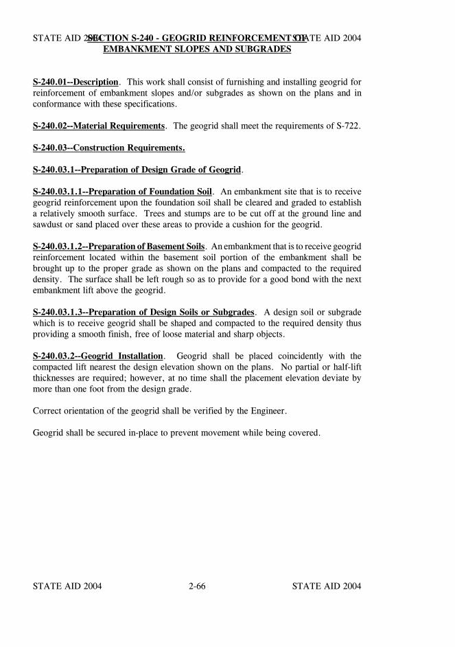
STATE AID 2004 STATE AID 2004
STATE AID 2004 STATE AID 20042-66
SECTION S-240 - GEOGRID REINFORCEMENT OFEMBANKMENT SLOPES AND SUBGRADES
S-240.01--Description. This work shall consist of furnishing and installing geogrid forreinforcement of embankment slopes and/or subgrades as shown on the plans and inconformance with these specifications.
S-240.02--Material Requirements. The geogrid shall meet the requirements of S-722.
S-240.03--Construction Requirements.
S-240.03.1--Preparation of Design Grade of Geogrid.
S-240.03.1.1--Preparation of Foundation Soil. An embankment site that is to receivegeogrid reinforcement upon the foundation soil shall be cleared and graded to establisha relatively smooth surface. Trees and stumps are to be cut off at the ground line andsawdust or sand placed over these areas to provide a cushion for the geogrid.
S-240.03.1.2--Preparation of Basement Soils. An embankment that is to receive geogridreinforcement located within the basement soil portion of the embankment shall bebrought up to the proper grade as shown on the plans and compacted to the requireddensity. The surface shall be left rough so as to provide for a good bond with the nextembankment lift above the geogrid.
S-240.03.1.3--Preparation of Design Soils or Subgrades. A design soil or subgradewhich is to receive geogrid shall be shaped and compacted to the required density thusproviding a smooth finish, free of loose material and sharp objects.
S-240.03.2--Geogrid Installation. Geogrid shall be placed coincidently with thecompacted lift nearest the design elevation shown on the plans. No partial or half-liftthicknesses are required; however, at no time shall the placement elevation deviate bymore than one foot from the design grade.
Correct orientation of the geogrid shall be verified by the Engineer.
Geogrid shall be secured in-place to prevent movement while being covered.
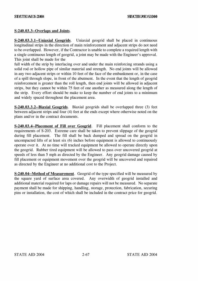
STATE AID 2004 STATE AID 2004
STATE AID 2004 STATE AID 20042-67
SECTION S-240 SECTION S-240
S-240.03.3--Overlaps and Joints.
S-240.03.3.1--Uniaxial Geogrids. Uniaxial geogrid shall be placed in continuouslongitudinal strips in the direction of main reinforcement and adjacent strips do not needto be overlapped. However, if the Contractor is unable to complete a required length witha single continuous length of geogrid, a joint may be made with the Engineer's approval.This joint shall be made for the full width of the strip by interlacing over and under the main reinforcing strands using asolid rod or hollow pipe of similar material and strength. No end joints will be allowedin any two adjacent strips or within 10 feet of the face of the embankment or, in the caseof a spill through slope, in front of the abutment. In the event that the length of geogridreinforcement is greater than the roll length, then end joints will be allowed in adjacentstrips, but they cannot be within 75 feet of one another as measured along the length ofthe strip. Every effort should be make to keep the number of end joints to a minimumand widely spaced throughout the placement area.
S-240.03.3.2--Biaxial Geogrids. Biaxial geogrids shall be overlapped three (3) feetbetween adjacent strips and four (4) feet at the ends except where otherwise noted on theplans and/or in the contract documents.
S-240.03.4--Placement of Fill over Geogrid. Fill placement shall conform to therequirements of S-203. Extreme care shall be taken to prevent slippage of the geogridduring fill placement. The fill shall be back dumped and spread on the geogrid inuncompacted lifts of at least six (6) inches before equipment is allowed to continuouslyoperate over it. At no time will tracked equipment be allowed to operate directly uponthe geogrid. Rubber tired equipment will be allowed to pass over uncovered geogrid atspeeds of less than 5 mph as directed by the Engineer. Any geogrid damage caused byfill placement or equipment movement over the geogrid will be uncovered and repairedas directed by the Engineer at no additional cost to the Project.
S-240.04--Method of Measurement. Geogrid of the type specified will be measured bythe square yard of surface area covered. Any overwidth of geogrid installed andadditional material required for laps or damage repairs will not be measured. No separatepayment shall be made for shipping, handling, storage, protection, fabrication, securingpins or installation, the cost of which shall be included in the contract price for geogrid.
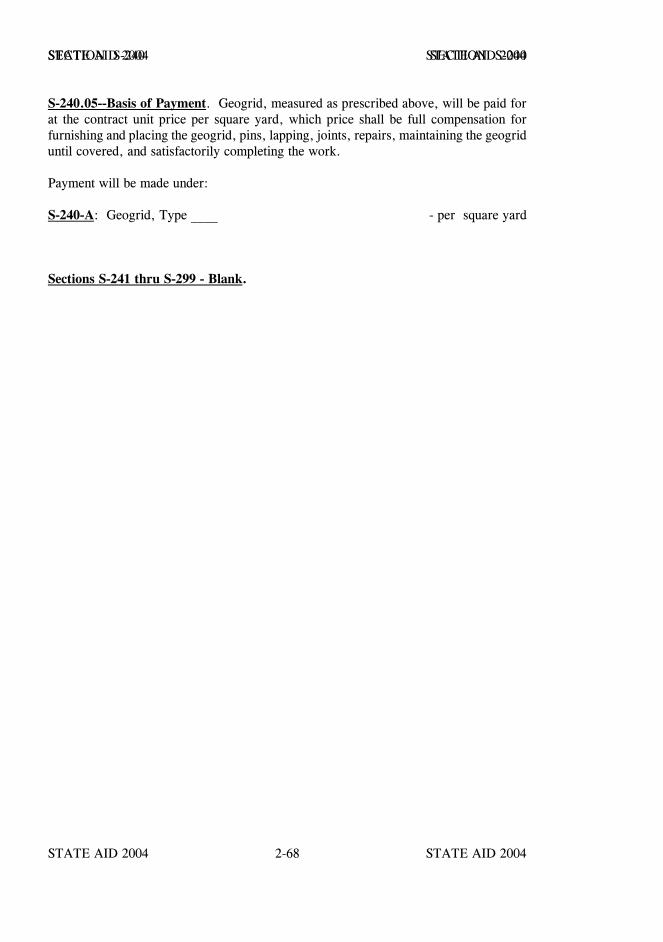
STATE AID 2004 STATE AID 2004
STATE AID 2004 STATE AID 20042-68
SECTION S-240 SECTION S-240
S-240.05--Basis of Payment. Geogrid, measured as prescribed above, will be paid forat the contract unit price per square yard, which price shall be full compensation forfurnishing and placing the geogrid, pins, lapping, joints, repairs, maintaining the geogriduntil covered, and satisfactorily completing the work.
Payment will be made under:
S-240-A: Geogrid, Type ____ - per square yard
Sections S-241 thru S-299 - Blank.
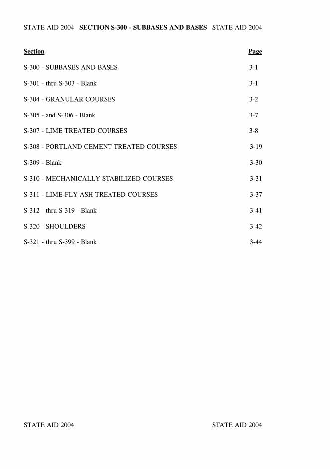
STATE AID 2004 STATE AID 2004
STATE AID 2004 STATE AID 2004
SECTION S-300 - SUBBASES AND BASES
Section Page
S-300 - SUBBASES AND BASES 3-1
S-301 - thru S-303 - Blank 3-1
S-304 - GRANULAR COURSES 3-2
S-305 - and S-306 - Blank 3-7
S-307 - LIME TREATED COURSES 3-8
S-308 - PORTLAND CEMENT TREATED COURSES 3-19
S-309 - Blank 3-30
S-310 - MECHANICALLY STABILIZED COURSES 3-31
S-311 - LIME-FLY ASH TREATED COURSES 3-37
S-312 - thru S-319 - Blank 3-41
S-320 - SHOULDERS 3-42
S-321 - thru S-399 - Blank 3-44

STATE AID 2004 STATE AID 2004
STATE AID 2004 STATE AID 2004
STATE AID 2004 STATE AID 2004
STATE AID 2004 STATE AID 20043-1
SECTION S-300 - SUBBASES AND BASES
The sections in the S-300 series include the specification requirements for subbases,bases, shoulders, and other work closely related to the construction of the pavementfoundation and shoulders. Bituminous base courses shall be constructed as specified inS-400.
The term "course" used in this series of sections shall be understood to mean a structuralcomponent of specified thickness. A course may consist of one or more layers.
Shoulder courses shown on the plans to be constructed separately from subbase or basecourses shall be performed in accordance with the provisions and requirements of S-320.
Sections S-301 thru S-303 - Blank.
STATE AID 2004 STATE AID 2004
STATE AID 2004 STATE AID 20043-2
SECTION S-304 - GRANULAR COURSES
S-304.01--Description. This work shall consist of furnishing granular materials and theconstruction of one or more courses of subbase, base, shoulders, or other requiredconstruction on a prepared foundation in reasonably close conformity with the lines,grades, and cross sections shown on the plans or established by the Engineer.
MATERIALS
S-304.02--Material Requirements. Unless otherwise specified, materials used on thiswork shall conform to the requirements of S-703.07.
General conditions governing the use of materials shall be as set out under S-106.
CONSTRUCTION REQUIREMENTS
S-304.03--Equipment. When measurement for payment is to be made by the ton, theContractor shall use approved platform scales capable of weighing the entire loadedvehicle. Scales and their use shall be in accordance with the requirements set out inS-40l.03.2.1.11, except they shall be installed at an approved location on or near theproject.
Rollers shall be of sufficient number, type, size, and weight to accomplish the requiredcompaction.
Watering equipment shall be pressurized, have spray bars with suitable nozzle openings,and have controls for applying varying quantities of water.
S-304.04--Production of Materials.
S-304.04.1--General. If payment is to be made from cross section (FM) measurements,the Contractor shall not begin excavation in a pit until after the Engineer has taken thenecessary cross sections. The Contractor shall be fully responsible for all material in thepit and shall protect the material from use or disposal for any reason other than for workincluded in the contract. He shall make good to the satisfaction of the Board ofSupervisors and State Aid Engineer for all loss or unauthorized use of material.
Prior to beginning mining operations, all necessary clearing and grubbing and strippingof the pit area shall have been performed to the satisfaction of the Engineer.
STATE AID 2004 STATE AID 2004
STATE AID 2004 STATE AID 20043-3
SECTION S-304 SECTION S-304
S-304.04.2--Mining and Mixing. Mining and mixing shall be carried out so that allmaterial meets the specified requirements for gradation, liquid limit, and plasticity index.
Mining and mixing shall be begun by opening the deposit in a manner that willimmediately expose the full face of the material. Except as otherwise permitted herein,mining and mixing shall ordinarily consist of a combination of excavating and mixing thematerial in such a manner that the material meets the specified requirements.
All pit operations shall be confined to daylight hours, except when otherwise permittedunder S-108.04.
Inspection of material as mined, mixed, and loaded from the pit will be made, and allobviously unsatisfactory material will be rejected. However, inspection or permission bythe Engineer to produce material from any portion of a deposit will not relieve theContractor of his responsibility to produce a satisfactory blend of material meeting thespecified requirements.
When the Contractor elects, with the authorization of the Engineer, to combine two ormore materials or to process a single material to provide that specified, all combining orprocessing shall be performed at the Contractor's expense. The sampling and testing andthe cost thereof to control the necessary proportioning and processing will be theresponsibility of the Contractor.
S-304.05--Preparation of Grade. The foundation on which granular material is to beplaced shall be prepared as set out in S-205. A section of prepared roadbed of sufficientlength to allow time for inspection, test, necessary corrections, and approval shall bemaintained at all times ahead of placing material.
S-304.06--Placing of Materials. The Contractor shall be responsible for furnishing amaterial that meets the requirements of the contract and in such quantity to produce thespecified compacted thicknesses. All material placed in excess of the tolerances allowed(See S-304.08.1) shall be removed and placed at other approved locations, or removedand hauled off the project without compensation.
If the compacted thickness of a course is to be more than eight inches, the course shall beconstructed in two or more layers of approximately equal thickness, and the compactedthickness of a single layer shall not exceed eight inches.
No granular materials shall be placed while frozen or placed on frozen materials.
When the Engineer determines that in-place material, including the top portion of thedesign soil, is wet to the degree that there is a possibility of rutting, deforming, ordisplacing the underlying material, the hauling operation shall be suspended.
STATE AID 2004 STATE AID 2004
STATE AID 2004 STATE AID 20043-4
SECTION S-304 SECTION S-304
The Contractor shall produce such material as is necessary to correct any deficiencies ingradation, liquid limit and plasticity index and shall reprocess as necessary to make suchcorrections or shall remove and replace, without additional compensation, any deficientmaterial placed in the work. In all cases of correcting deficiencies on the roadbed, theContractor shall be fully responsible for any damage to the underlying course(s) and otherwork.
S-304.07--Blending. As soon as practicable after the material has been initially shaped,the entire volume of material for the course or layer being placed shall be processed andblended by blading in such a manner and as many times as necessary to produce a coursevisually uniform in gradation, color, liquid limit, and plastic limit. Care shall beexercised during the blending process to prevent contamination with underlying material.The Contractor shall be fully responsible for damage to or contamination with underlyingor other unlike material and shall make the corrections deemed necessary withoutadditional compensation. The requirement for blending will not be waived by theEngineer, and required mixing or further processing under subsequent items of work willnot relieve the Contractor from the complete performance of blending as specified in thissubsection, except for shoulders as follows:
When granular material is required to be placed adjacent to pavement in place, blendingin place will not be required. Blending shall be performed to the satisfaction of theEngineer prior to placement of the material on shoulders.
S-304.08--Shaping, Compacting, and Finishing. Each course or layer of material shallbe shaped to the required section, watered or aerated as necessary to produce the requiredmoisture content, and compacted. Throughout the compaction operation, the shape of thecourse or layer shall be maintained by blading and rolling so that the aggregates areuniformly distributed and firmly keyed.
Shaping and compaction shall be carried out in a manner that will prevent lamination andshall continue until the entire depth and width of the course or layer has reached therequired density. Surface compaction and finishing shall be performed so as to producea smooth, closely knit surface that is free from lamination, cracks, ridges or loosematerial. The finished surface shall conform (within allowable tolerances) to the requiredsection and established lines and grades.
Prior to subsequent construction or final acceptance all irregularities, depressions, softspots, and other deficiencies found by the Engineer shall be corrected to meet therequirements of these specifications without additional compensation.
If the mixture contains plus No. 4 aggregate and the course is to serve as a base forbituminous pavement, after compaction and finishing at least one complete coverage shallbe made with a steel wheel tandem roller. The resulting surface shall be sprinkled asnecessary to maintain the required moisture content and shall be thoroughly compactedand sealed with a pneumatic roller.
Crushed stone shall be placed in layers not to exceed four (4) inches compacted depth andshall conform to the density requirements stated.
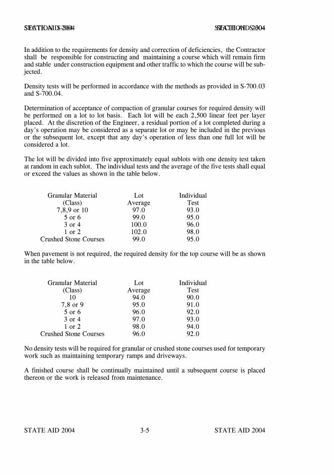
STATE AID 2004 STATE AID 2004
STATE AID 2004 STATE AID 20043-5
SECTION S-304 SECTION S-304
In addition to the requirements for density and correction of deficiencies, the Contractorshall be responsible for constructing and maintaining a course which will remain firmand stable under construction equipment and other traffic to which the course will be sub-jected.
Density tests will be performed in accordance with the methods as provided in S-700.03and S-700.04.
Determination of acceptance of compaction of granular courses for required density willbe performed on a lot to lot basis. Each lot will be each 2,500 linear feet per layerplaced. At the discretion of the Engineer, a residual portion of a lot completed during aday's operation may be considered as a separate lot or may be included in the previousor the subsequent lot, except that any day's operation of less than one full lot will beconsidered a lot.
The lot will be divided into five approximately equal sublots with one density test takenat random in each sublot. The individual tests and the average of the five tests shall equalor exceed the values as shown in the table below.
Granular Material Lot Individual(Class) Average Test
7,8,9 or 10 97.0 93.05 or 6 99.0 95.03 or 4 100.0 96.01 or 2 102.0 98.0
Crushed Stone Courses 99.0 95.0
When pavement is not required, the required density for the top course will be as shownin the table below.
Granular Material Lot Individual(Class) Average Test
10 94.0 90.07,8 or 9 95.0 91.05 or 6 96.0 92.03 or 4 97.0 93.01 or 2 98.0 94.0
Crushed Stone Courses 96.0 92.0
No density tests will be required for granular or crushed stone courses used for temporarywork such as maintaining temporary ramps and driveways.
A finished course shall be continually maintained until a subsequent course is placedthereon or the work is released from maintenance.
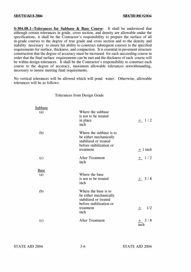
STATE AID 2004 STATE AID 2004
STATE AID 2004 STATE AID 20043-6
SECTION S-304 SECTION S-304
S-304.08.1--Tolerances for Subbase & Base Course: It shall be understood thatalthough certain tolerances in grade, cross section, and density are allowable under thespecifications, it shall be the Contractor's responsibility to prepare the surface of allin-grade courses to the degree of true grade and cross section and to the density andstability necessary to insure his ability to construct subsequent courses to the specifiedrequirements for surface, thickness, and compaction. It is essential in pavement structureconstruction that the degree of accuracy must be increased for each succeeding course inorder that the final surface requirements can be met and the thickness of each course willbe within design tolerances. It shall be the Contractor's responsibility to construct eachcourse to the degree of accuracy, maximum allowable tolerances notwithstanding,necessary to insure meeting final requirements.
No vertical tolerances will be allowed which will pond water. Otherwise, allowabletolerances will be as follows:
Tolerances from Design Grade
Subbase(a) Where the subbase
is not to be treatedin place + 1 / 2inch
(b) Where the subbase is to be either mechanicallystabilized or treated before stabilization ortreatment + 1 inch
(c) After Treatment + 1 / 2inch
Base(a) Where the base
is not to be treated + 3 / 8inch
(b) Where the base is to be either mechanicallystabilized or treated before stabilization ortreatment + 1/2inch
(c) After Treatment + 3 / 8inch
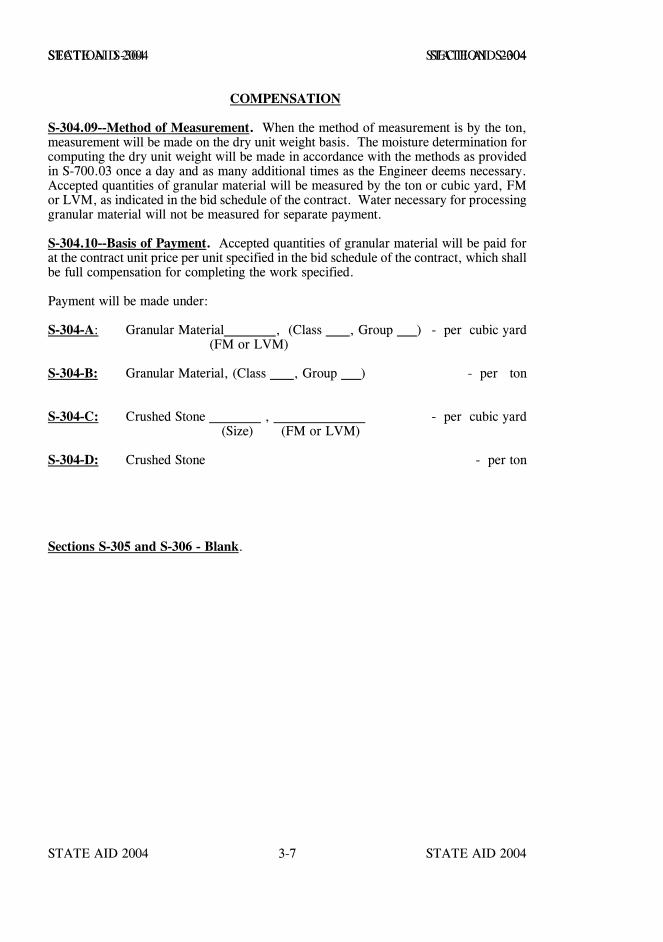
STATE AID 2004 STATE AID 2004
STATE AID 2004 STATE AID 20043-7
SECTION S-304 SECTION S-304
COMPENSATION
S-304.09--Method of Measurement. When the method of measurement is by the ton,measurement will be made on the dry unit weight basis. The moisture determination forcomputing the dry unit weight will be made in accordance with the methods as providedin S-700.03 once a day and as many additional times as the Engineer deems necessary.Accepted quantities of granular material will be measured by the ton or cubic yard, FMor LVM, as indicated in the bid schedule of the contract. Water necessary for processinggranular material will not be measured for separate payment.
S-304.10--Basis of Payment. Accepted quantities of granular material will be paid forat the contract unit price per unit specified in the bid schedule of the contract, which shallbe full compensation for completing the work specified.
Payment will be made under:
S-304-A: Granular Material , (Class , Group ) - per cubic yard (FM or LVM)
S-304-B: Granular Material, (Class , Group ) - per ton
S-304-C: Crushed Stone , - per cubic yard
(Size) (FM or LVM)
S-304-D: Crushed Stone - per ton
Sections S-305 and S-306 - Blank.
STATE AID 2004 STATE AID 2004
STATE AID 2004 STATE AID 20043-8
SECTION S-307 - LIME TREATED COURSES
S-307.01--Description. This work shall consist of constructing one or more courses ofa mixture of soil, hydrated lime, and water or a mixture of soil and hydrated lime slurry,all in accordance with these specifications and in reasonably close conformity with thelines, grades, thicknesses, and typical cross sections shown on the plans or established bythe Engineer. When lime slurry is used, the Contractor shall mix hydrated lime withwater to produce lime slurry or, at his option, produce lime slurry at the job site by theuse of equipment specifically manufactured for the slaking of quick lime.
The use of quick lime by the dry application method will not be allowed unless the limemeets the requirements of S-714.03.3.2 for Dry Quick Lime.
The work shall include preparation of the roadbed, incorporation of lime or lime slurry,and processing in accordance with one of the following methods:
Class A lime treatment shall consist of spreading and incorporating thespecified percentage of lime in two increments in the following sequence:spreading the first increment, initial mixing, mellowing, spreading thesecond increment, final mixing, compacting, and finishing.
Class B lime treatment shall consist of spreading the specified percentageof lime, initial mixing, mellowing, final mixing, compacting, and finishing.
Class C lime treatment shall consist of spreading the specified percentageof lime, mixing, compacting, and finishing.
The soil profile is normally not available before a project is advertised and it is notpossible to determine the precise class of lime treatment required. Design considerations,therefore, sometimes necessitate changing the class(es) of lime treatment in order to obtainthe contemplated structural qualities without unnecessary cost.
The Board and the State Aid Engineer reserve the right to modify by CCR the class oftreatment or to eliminate lime treatment from certain sections or to add other sections forlime treatment depending on the results of soil tests, in conformance with S-100.
STATE AID 2004 STATE AID 2004
STATE AID 2004 STATE AID 20043-9
SECTION S-307 SECTION S-307
MATERIALS
S-307.02--Material Requirements.
S-307.02.1--Materials to be Treated. The material to be treated shall consist of existingroadbed material or material added as directed. Particles of aggregate retained on a threeinch sieve and deleterious substances such as roots, stumps, grass, turf, and othervegetable matter shall be removed from the soil. Material considered by the Engineer tobe unsuitable for stabilization shall be removed and replaced with suitable material.
S-307.02.2--Water. Water used in this construction shall meet the requirements ofS-714.01.3.
S-307.02.3--Lime. Lime shall meet the requirements of S-714.03.
Lime shall be stored and handled in closed, weather-proof containers until distribution onthe section of road being processed. If local storage is provided, lime shall be used onlyfrom approved storage facilities and shall meet these requirements at the time of use.
The Contractor is reminded of the highly caustic characteristic of quick lime and shallinstruct employees as to preventive and protective measures to take prior to their workingwith quick lime. Further, the Contractor shall take all precautions necessary to preventinjury to persons not in his employ and to livestock. Quick lime which is spilled ordeposited at places other than on areas designated to be treated shall be immediatelypicked up, buried, or slaked by wetting to eliminate the hazard.
S-307.02.4--Curing Seal. Curing seal shall be Emulsified Asphalt, Grade EA-1, SS-1,CMS-2h, or MS-2h meeting the applicable requirements of S-702.
S-307.03--Equipment. The methods and equipment used in performing the work shallconform to the requirements of S-108.05. Equipment necessary for proper prosecutionof the work shall be on the project and approved by the Engineer prior to its use.
When bulk lime is used, and application of lime is made from equipment other than thedelivery transport, batch-type or platform scales shall be provided. Batch type scales shallmeet the requirements set out for scales in MDOT Specifications Subsection 501.03.2.3.Platform scales shall meet the requirements of S-401.03.2.1.11. All scales shall belocated at approved locations on or near the project.
STATE AID 2004 STATE AID 2004
STATE AID 2004 STATE AID 20043-10
SECTION S-307 SECTION S-307
When bulk lime is used, the Contractor shall provide approved mechanical spreader(s)having adjustable strike-off gate(s), or other approved spreading equipment constructedso as to provide positive control of the spread. Approval of a spreader will be contingentupon its known or demonstrated ability to make distribution of lime within the tolerancesallowable.
Mixing and scarifying equipment shall be capable of positive depth control. Mixing shallbe performed with approved rotary type mixers or other approved equipment.
Rollers shall be of sufficient number, type, size, and weight to accomplish the requiredcompaction.
The Contractor may use approved alternate equipment provided it produces work meetingthe requirements of these specifications.
CONSTRUCTION REQUIREMENTS
S-307.04--General. Quantities and percentages of lime shown on the plans and proposalare estimated. The actual application rate will be established from tests made just priorto beginning treatment. The Contractor is hereby advised that the estimated contractquantity of lime is based on application rates of hydrated lime.
It is necessary that lime treated materials be kept moist at all times. It shall be theContractor's responsibility to provide sufficient equipment and keep all partiallyconstructed or completed lime stabilized layers sufficiently and continually moist until asucceeding layer has been placed thereon or until release of maintenance of the project.
The first section of each mixing operation, both initial and final, will serve as a testsection. The length of the test section (not less than three hundred fifty (350) linear feetnor more than five hundred (500) linear feet for the designated width) will be determinedby the capabilities of the equipment provided to perform the work. The Engineer and theContractor will evaluate the results of the test section in relation to contract requirements.In case the Engineer determines the work is not satisfactory, the Contractor shall revisehis procedures and augment or replace equipment as necessary to assure work iscompleted in accordance with the contract and shall correct any deficient work at noadditional cost to the Project.
Also within the test section and only when the dry-application method of quicklime isused, a sample of the soil-lime-water mixture shall be taken after the completion of themixing operation. This sample shall be taken, by the Contractor, to an independenttesting laboratory to determine,using the X-ray Diffraction Test or the Titration AnalysisTest, the percent of hydration. After the completion of the test section, the Contractorshall not continue operations until the results of the test sample have been determined.The Contractor shall provide the Engineer with three copies of a certified test reportshowing that the non-hydrated content of the sample has not exceeded one percent (1.0%)of the total mix. Should the sample not meet the hydration requirements, the Contractorshall re-mix the section and add sufficient water until satisfactory results are achieved.All testing costs associated with determining the hydration efficiency of the sample(s) willbe at no additional cost to the Project. The Engineer reserves the right to make hydrationverification checks of the soil-lime-water mixture at any time.

STATE AID 2004 STATE AID 2004
STATE AID 2004 STATE AID 20043-11
SECTION S-307 SECTION S-307
S-307.05--Preparation of Grade. Before treatment, the roadbed shall be prepared inaccordance with the requirements of S-205 (Reference is made to Figure 1, S-100).
Prior to the application of dry hydrated lime, a light windrow shall be bladed along theedges of the area to be treated, or the surface on which the lime is to be applied shall bescarified to retain the spread.
Prior to the application of slurry, the full width of the area shall be scarified or partiallypulverized to the depth necessary to retain the lime slurry until it has been incorporated.
The depth of scarification shall be carefully controlled so that the surface of the roadbedbelow the scarified material will remain undisturbed and conform as closely as possibleto the established cross section.
S-307.06--Application of Lime. The rate of application of lime shall be as specified.The first application for Class A treatment shall not be made after October 15, and nolime shall be applied between November 1 and March 1 without written authorizationfrom the State Aid Engineer.
Lime shall not be applied unless the temperature in the shade is at least 40°F and isexpected to remain at least 40°F during the mixing period. In no case shall lime beapplied on a frozen foundation.
Application of lime shall be accomplished by either an approved "dry application" or"slurry application" method.
The following guide lines will govern the acceptability of the method to be used:
Dry Application. Lime applied by this method shall be spread uniformlyand shall be sprinkled with sufficient water to prevent loss of lime by wind.Spreading of lime when wind and weather conditions are unfavorable willnot be permitted nor will spreading of lime by motor patrol be acceptable.
STATE AID 2004 STATE AID 2004
STATE AID 2004 STATE AID 20043-12
SECTION S-307 SECTION S-307
The Engineer reserves the right to check, at any time, the dispersion ofquick lime dust in the atmosphere. At no time shall the atmospheredispersion of quick lime dust exceed a rate of 30,000 µg/m3, measured ata distance of 100 feet.
Slurry Application. Lime applied by this method shall be mixed with waterin approved agitation equipment and applied to the roadbed as a thin watersuspension or slurry. The distributing equipment shall be equipped toprovide continuous agitation of the slurry until applied on the roadbed.The proportion of lime shall be such that the "Dry Solids Content" shallbe at least thirty (30) percent by weight.
The distribution of lime at the rate specified shall be attained by one or more passes overa measured section until the specified percentage of lime has been spread. After eachsuccessive pass, the material shall be incorporated into the soil with the mixing equipment.Additional water, if necessary, shall be added and mixed into the mass to hastenmellowing.
Payment will not be made for lime that has been spread and exposed for a period of sixhours or more before mixing. Such areas shall be treated again with the full required rateof application.
Additional lime shall be added at the Contractor's expense to all sections on whichexcessive loss has occurred due to washing or blowing.
The quantity of lime applied on a section shall be spread uniformly and shall not varymore than plus or minus five percent of the quantity ordered. No payment will be madefor lime application exceeding the five percent plus tolerance. When the quantity appliedis deficient by more than five percent, additional lime shall be applied prior to mixing.
S-307.07--Mixing.
S-307.07.1--Initial Mixing. For Class A and Class B treatments, the lime and water shallbe incorporated uniformly into the soil. The mixing and watering operation shall becontinued until a homogeneous mixture that will pass a three inch sieve is obtained. Aftersatisfactory mixing is obtained, the layer shall be reshaped to line, grade, and section andsealed with a light roller no later than the next day following mixing. The sealedmixture shall then be left to mellow for the period specified in the lime mix designfurnished by the MDOT Central Laboratory or other approved laboratory. The mellowingperiod will be measured in degree days. This period will not be less than five (5) calendardays nor more than twenty (20) calendar days. The temperature to be used to determinethe degree days mellowing period will be the average of the high and low temperaturesfor each day of the mellowing period. In the event the average is 40oF or less, that daywill not be used in computing the degree days mellowing period. The recommendeddegree days for the mellowing period may be reduced by the Engineer providedpulverization during final mixing is documented by sieve analysis.
STATE AID 2004 STATE AID 2004
STATE AID 2004 STATE AID 20043-13
SECTION S-307 SECTION S-307
During the mellowing period the partially treated course or layer shall be kept moist bysprinkling. All sections on which the surface becomes dry during the mellowing periodshall be reprocessed to the satisfaction of the Engineer or reconstructed in accordance withthe specifications.
For Class C treatment, the lime and water shall be incorporated uniformly into the soil.The mixing and water application shall be continued until a homogeneous mixture ofwhich one hundred (100) percent of the material by dry weight, exclusive of gravel andstone, will pass a one inch sieve and sixty (60) percent will pass a No. 4 sieve. At thecompletion of moist mixing and during the compaction operations, the percentage ofmoisture shall be that necessary to obtain the required density. There will be nomellowing period, and compaction shall begin immediately. The mixing, water appli-cation, and final compaction shall be completed during the same work day.
S-307.07.2--Final Mixing. After the required mellowing period (Class A and B), thelayer shall be scarified, and in the case of Class A treatment the second application oflime added.
The layer shall then be remixed as prescribed in the initial mixing operations. Mixingshall continue until one hundred (100) percent of material by dry weight, exclusive ofgravel and stone, will pass a one inch sieve and sixty (60) percent will pass a No. 4 sieve. At the end ofmixing and during compaction, the moisture in the mixture shall be that necessary toobtain the required density.
S-307.07.3--Thickness and Width Requirements. For the purpose of determiningreasonable conformity with the designated thickness of a course, it shall be understoodthat the depth of a course shall not vary from the designated thickness by more than plusor minus one inch. All sections not in reasonably close conformity because of deficientthickness shall be reprocessed to meet specification requirements. All sections not inreasonably close conformity because of excess thickness shall have additional lime appliedand shall be reprocessed to meet specification requirements at no additional cost to theProject.
For the purpose of determining reasonable conformity with the designated width of acourse, it shall be understood that the width of a course shall not vary from the designatededge lines by more than plus or minus three inches.
S-307.08--Compaction. Compaction of the mixture shall begin immediately after therequired mixing operation has been completed.
STATE AID 2004 STATE AID 2004
STATE AID 2004 STATE AID 20043-14
SECTION S-307 SECTION S-307
Compaction shall be completed during same day it was begun and shall provide uniformand continuous compaction from bottom to top of the layer. The mixture shall be aeratedor watered as necessary to obtain the moisture content required for the required density.
Throughout the entire compaction operation, depression, defective areas, or soft spotswhich develop shall be corrected immediately by scarifying the area, adding lime whenrequired, or removing the material, and reshaping and compacting in accordance withthese specifications and at the Contractor's expense.
Density tests will be performed in accordance with the methods as provided in S-700.03and S-700.04.
Determination of acceptance of compaction of Classes A, B, and C lime treated designsoil will be performed on a lot to lot basis. Each lot will be 2,500 linear feet per layerplaced. At the discretion of the Engineer, a residual portion of a lot completed during aday's operation may be considered as a separate lot or may be included in the previousor subsequent lot, except that any day's operation of less than one full lot will beconsidered a lot.
The lot will be divided into five approximately equal sublots with one density test takenat random in each sublot. The average of the five density tests shall equal or exceed 95.0percent with no single density test below 91.0 percent. Sublots with a density below 91.0percent shall be corrected at no additional cost to the Projest and retested for acceptance.
S-307.09--Finishing, Curing, Protection, and Maintaining. The surface of the layershall be smooth and conform to the lines, grades, and typical cross section(s) shown onthe plans or established by the Engineer. The surface tolerances will meet therequirements of S-304.08.1.
The surface of the lime treated course shall be kept moist and otherwise satisfactorilymaintained until placement of the subsequent course or layer. If the next course is to begranular material, the first layer placed shall be at least four inches in thickness. Duringplacement of the subsequent course or layer, the least possible hauling will be permittedover the unprotected lime treated course. Except as provided in the following paragraph,the subsequent layer or course shall be placed and compacted within two days after thelime treated course has been finished.
At his option, the Contractor may defer placement of the subsequent course or layer forup to twenty-one (21) days by placing a bituminous curing seal over the lime treatedcourse within two days after finishing the course. The lime treated course shall be keptmoist until application of the curing seal. When a curing seal is used, the emulsifiedasphalt shall be applied at the consistency specified in S-702 without further dilution. Therate of application shall be within the limits of 0.10 to 0.25 gallon per square yard asdirected by the Engineer.
STATE AID 2004 STATE AID 2004
STATE AID 2004 STATE AID 20043-15
SECTION S-307 SECTION S-307
Should the Contractor fail to cover a lime treated course with the curing seal orsubsequent course within the times specified, the Engineer will suspend all other workand withhold payment of the current estimate(s) until all damage resulting therefrom isrepaired and the treated course is covered with the curing seal or the subsequent course,as the case may be.
A subsequent course shall not be placed on the sealed course for at least seven (7)calendar days. If local traffic is permitted to use the roadway during this seven day periodthen load restrictions should be imposed on the vehicles. When necessary for themaintenance of vehicular traffic, the Contractor shall furnish and apply blotter materialin accordance with S-408.03 and S-408.08. Maintenance of the curing seal shall be inaccordance with the provisions of S-408.09.
All damage, as determined by the Engineer, resulting from the Contractor's failure toprotect and cure the treated course as specified herein or from freezing that may occur ina treated course prior to being covered by the next course shall be corrected by repro-cessing the course with Class C treatment at the Contractor's expense. The Contractorshall add the quantity of lime necessary to restore the CBR of the damaged material tothat shown on the mix design. In no case shall the quantity of added lime be less thantwo percent by weight.
COMPENSATION
S-307.10--Method of Measurement. Accepted soil-lime-water mixing will be measuredby the square yard, complete in place, for each course designated on the plans.
If a change in the class of treatment is made, as provided in S-307.01, each class oftreatment constructed will be measured separately.
Lime incorporated in accepted treatment will be measured by the ton in accordance withprovisions of S-109. Lime in excess of the tolerance allowable and all lime required tobe furnished by the Contractor at no additional cost to the Project will be deducted frommeasured quantities.
The basis of pay for jobsite slaked lime slurry shall be the “calculated method” using thecertified lime purity for each truckload as follows:
Pure Quick lime (Ca O) x 1.32 = Hydrated Lime (Ca (OH)2)
Quick Lime delivered x % purity x 1.32 = A
Quick Lime delivered x % inert material x 1.0 = B
A + B = Total Hydrated Lime produced (Pay Quantity)

STATE AID 2004 STATE AID 2004
STATE AID 2004 STATE AID 20043-16
SECTION S-307 SECTION S-307
The basis of pay for quick lime by the dry application method shall be the "calculatedmethod" using the certified lime purity for each truckload as follows:
Pure Quick Lime (Ca O) x 1.32 = Hydrated Lime (Ca (OH)2
Quick Lime delivered x % purity x 1.32 = A
Quick Lime delivered x % inert material x 1.0 = B
A + B = Total Hydrated Lime produced (Pay Quantity)
Water and curing seal will not be measured for separate payment.
S-307.11-Basis of Payment. Accepted quantities of soil-lime-water mixing and limemeasured as provided in S-307.10 will be paid for as follows:
Soil-lime-water mixing of the class(es) specified or ordered will be paid for at thecontract unit price, or adjusted unit price as provided herein, per square yard.
Quantities of soil-lime-water mixing changed as ordered will be paid for at thecontract unit price for soil-lime-water mixing, plus or minus as applicable, theamount indicated in the following schedule:

STATE AID 2004 STATE AID 2004
STATE AID 2004 STATE AID 20043-17
SECTION S-307 SECTION S-307
SCHEDULE
Price Adjustment Due to Change in Class of Lime Treatment
PlanDepth
ClassBid
ClassOrdered
Adjusted Price Equals
A B Price Bid Minus $0.05 per square yard
A C Price Bid Minus $0.10 per square yard
6 " B A Price Bid Plus $0.05 per square yard
B C Price Bid Minus $0.05 per square yard
C A Price Bid Plus $0.10 per square yard
C B Price Bid Plus $0.05 per square yard
A B Price Bid Minus $0.10 per square yard
A C Price Bid Minus $0.15 per square yard
8" B A Price Bid Plus $0.10 per square yard
B C Price Bid Minus $0.05 per square yard
C A Price Bid Plus $0.15 per square yard
C B Price Bid Plus $0.05 per square yard
If 10 inch course is designated, use MDOT Specifications.
STATE AID 2004 STATE AID 2004
STATE AID 2004 STATE AID 20043-18
SECTION S-307 SECTION S-307
Lime will be paid for at the contract unit price per ton.
Payment for removal and disposal of unsuitable material will be made under otherprovisions of the contract.
Prices thus paid shall be full compensation for completing the work specified.
Payment will be made under:
S-307-A: ” Soil-Lime-Water Mixing (Class A) - per square yard
S-307-B: ” Soil-Lime-Water Mixing (Class B) - per square yard
S-307-C: ” Soil-Lime-Water Mixing (Class C) - per square yard
S-307-D: Lime - per ton
STATE AID 2004 STATE AID 2004
STATE AID 2004 STATE AID 20043-19
SECTION S-308 - PORTLAND CEMENT TREATED COURSES
S-308.01--Description. This work shall consist of constructing one or more courses ofa mixture of cement, soil or soil aggregate, and water in accordance with thesespecifications and in reasonably close conformity with the lines, grades, and cross sectionsshown on the plans or established by the Engineer.
MATERIALS
S-308.02--Material Requirements.
S-308.02.1--Materials to be Treated. The materials to be treated shall consist ofmaterials in place or placed under this contract.
S-308.02.2--Water. Water shall conform to the requirements of S-714.01.3
S-308.02.3--Portland Cement. Cement shall conform to the requirements of S-701.
Cement shall be stored and handled in closed, weatherproof containers until distributionto the section of road being processed. If storage bins are used, they shall be completelyenclosed.
When bulk cement is used, the Contractor shall provide means suitable to the Engineerfor applying. The Engineer shall weigh shipments at random for verification of bulkcement quantities.
When bag cement is furnished, the bag shall bear the manufacturer's certified weight.Bags varying more than five percent from the certified weight will be rejected, and theaverage weight of bags in any shipment, determined by weighing 50 bags taken atrandom, shall not be less than the certified weight.
S-308.02.4--Curing Seals. Curing Seals shall meet the requirements of S-307.02.4.
S-308.03--Equipment.
S-308.03.1--General. Equipment necessary for proper prosecution of work shall be onthe project and approved by the Engineer prior to its use.
When bulk cement is used and application of cement is made from equipment other thanthe delivery transport, batch-type or platform scales shall be provided. Batch type scalesshall meet the requirements of MDOT Subsection 501.03.2.3. Platform scales shall meetthe requirements of S-401.03.2.1.11. All scales shall be located at approved locations onor near the project.
STATE AID 2004 STATE AID 2004
STATE AID 2004 STATE AID 20043-20
SECTION S-308 SECTION S-308
Approval of cement spreaders will be contingent upon their known or demonstrated abilityto make distribution of cement within allowable tolerances.
Watering equipment shall be pressurized, have one or more spray bars with suitablenozzle openings, and have positive controls for applying varying quantities of water.
Mixing shall be performed with multiple pass mixers, single pass mixers, travelingmixing plants, or central mixing plants, as specified in the contract.
Mixing and scarifying equipment for the road mix methods shall be capable of positivedepth control.
Rollers shall be of sufficient number, type, size, and weight to accomplish the requiredcompaction.
Leakage of water, oil, grease, or other liquids from equipment shall be immediatelycorrected, or the leaking equipment removed from the work and replaced withsatisfactory equipment.
S-308.03.2--Multiple Pass Mixers. Multiple pass mixers shall be the rotary-type withsufficient tines and so constructed and operable as to obtain by multiple passes uniformmixture of the cement, soil-aggregate, and water for the full depth of the course.
S-308.03.3--Single Pass Mixers. Single pass mixers shall be the pugmill type soconstructed and operable as to measure the required quantity of water through apressurized spray and obtain by a single pass a uniform mixture of the cement, soil orsoil-aggregate, and water for the full depth of the course.
S-308.03.4--Traveling Plant Mixers. Traveling mixing plants shall be either of thetype which will pulverize the material to be treated and mix it and cement with theproper quantity of water without picking the materials up from the roadway, or of thepugmill type which elevates the materials into a pugmill for mixing. The plant shallbe equipped with a device which will accurately control and measure the quantity of waterused. Worn scarifying and mixing parts shall be replaced, and extra parts shall beavailable for replacements.
S-308.03.5--Central Plant Mixers. Central mixing plants shall be either the batch typeusing revolving blade or rotary drum mixers or the continuous mixing type. The cement,soil or soil-aggregate, and water may be proportioned either by weight or by volume.There shall be means by which the Engineer can readily verify the proportions in eachbatch or the rate of flow for continuous mixing.
STATE AID 2004 STATE AID 2004
STATE AID 2004 STATE AID 20043-21
SECTION S-308 SECTION S-308
The charge and mixing time in a batch mixer, or the rate of feed to a continuous mixer,shall be such as to obtain complete mixing of all the material. Dead areas in the mixer,in which the material does not move or is not sufficiently agitated, shall be corrected. Theplant shall deliver a uniform mixture meeting all specified requirements.
CONSTRUCTION REQUIREMENTS
S-308.04--General. The intent of these specifications is to provide for a cement treatedcourse of designated thickness consisting of a uniform mixture of cement, soil orsoil-aggregate, and water; constructed at the required moisture content; to the requireddensity; free of laminations, construction cracks, ridges, or loose material; and with asmooth, closely knit surface meeting the requirements of these specifications.
If the thickness of a course is designated to be more than eight inches, the course shall beconstructed in two or more layers of approximately equal thickness. The compactedthickness of a single layer shall not exceed eight inches.
Prior to incorporating cement, the base or subbase course will be graded to conform tothe lines and grades furnished by the Engineer.
Immediately prior to placement of a course to be cement treated on an in-place cementtreated course, the surface of the in-place course shall be thoroughly moistened.
Except as necessary to provide the required curing and maintenance of traffic, allequipment and traffic shall be kept off each completed cement treated course until it isthoroughly cured. Unless otherwise specified, the curing period shall be seven daysexclusive of days during which the temperature falls below 35oF.
Prior to joining a previous day's work, or work more than two hours old, a verticalconstruction joint, normal to the center-line of the roadbed, shall be made in the oldwork. The joint shall be moistened if dry. Additional processing shall not be started untilthe construction joint has been approved by the Engineer.
When vertical longitudinal joints are specified or permitted, the joints shall be constructedparallel to the centerline by cutting into the existing edge for a sufficient distance toprovide a vertical face for the depth of the course. The material cut away may bedisposed of by spreading in a thin layer on the adjacent lane to be constructed, orotherwise disposed of in a satisfactory manner. If dry, cut joints shall be moistenedimmediately in advance of placing fresh mixture adjacent to them.
STATE AID 2004 STATE AID 2004
STATE AID 2004 STATE AID 20043-22
SECTION S-308 SECTION S-308
The first section of each cement treated course constructed will serve as a test section.The length of the test section (not less than three hundred fifty (350) linear feet nor morethan five hundred (500) linear feet for the designated width) will be determined by thecapability of the equipment provided to perform the work. The Engineer and theContractor will evaluate results of the test section in relation to contract requirements.
In case the Engineer determines the work is not satisfactory, the Contractor shall revisehis procedures and augment or replace equipment as necessary to assure work completedin accordance with the contract, and shall correct all deficient work at no additional costto the County.
S-308.05--Road-Mix Method. When the road-mix method is used, no hauling ofmaterials for a subsequent course will be permitted directly on a completed cement-treatedcourse. Materials for a higher course shall be kept bladed down as it is placed, andhauled over with truck traffic being distributed over its entire width.
Where reconstruction is required, it shall be for the full depth and width of the deficientsection. The adding of a thin layer or strip of cement-treated material will not bepermitted. All sections to be reconstructed later than the two-hour period allowed forinitial compaction shall have additional cement. When reconstruction is to be performedwithin forty-eight (48) hours after the initial application of cement, fifty (50) percent ofthe original quantity of cement shall be added. When reconstruction is to be later thanforty-eight (48) hours after the initial application of cement, an engineering study will bemade, and the Engineer will specify the additional quantity of cement to be added, or theEngineer may require the total removal of the deficient work. If removal is required, acourse meeting the requirements of the contract shall be constructed with new materials.
In all cases where reconstruction is performed by the addition of cement, the cement,in-place materials, and water shall be thoroughly mixed, processed, compacted, andfinished in accordance with the requirements of the contract.
Where deficient work is removed, the removal and disposal shall be performed in amanner satisfactory to the Engineer, and all materials shall be replaced and a new courseconstructed in accordance with the requirements of the contract.
The furnishing of all materials for and all reconstruction shall be performed by theContractor at no additional cost to the project.

STATE AID 2004 STATE AID 2004
STATE AID 2004 STATE AID 20043-23
SECTION S-308 SECTION S-308
S-308.06--Central Plant Mix Method. When the central plant mix method is used,material for a higher course may be hauled directly on a completed and properly curedcement treated course for the minimum distance necessary. The Contractor shall be fullyresponsible for all damages to the course.
Prior to placement of a course processed by the plant mix method, the Contractor shallhave made satisfactory provisions for completing the section to specified requirements.To comply with these requirements, the Contractor shall, if necessary, use materials(s)specified for contiguous shoulder construction.
The mixture shall be hauled to the roadway in trucks equipped with protective covers.The mixture shall be uniformly placed on a moistened foundation by full-width spreader,or partial-width spreaders working in echelon and spaced close enough together to placethe entire course in one operation. The elapsed time between the start of moist mixingand the start of compaction on the roadway shall not exceed sixty (60) minutes. Theelapsed time between placement of cement treated material in adjacent lanes shall notexceed thirty (30) minutes, except where longitudinal construction joints are specified,or when joints are permitted by the Engineer in case of emergency. In the latter caselongitudinal joints conforming to the requirements of these specifications will be permittedonly to allow placement of material in transit at the time of the emergency.
The material shall be placed, shaped, and compacted so that the completed course willbe uniform, smooth, and conform to all of the requirements specified.
Dumping of the mixture in piles or windrows and spreading with a motor grader orsimilar equipment will not be permitted except in areas where such spreading isreasonable, as in the case of small areas inaccessible to mechanical spreaders.
In all cases where reconstruction is required, the deficient work shall be removed,disposed of, and replaced with material’s meeting the requirements of these specifications.Reconstruction shall be for the full depth and width of the deficient section.
S-308.07--Preparation of Grade. Prior to construction or reconstruction, the foundationshall be prepared in accordance with the requirements of S-205. The tolerance fromdesign grade immediately prior to spreading cement shall be plus or minus one-half(+ 1/2) inch for bases.
S-308.08--Preparation of Materials. Particles of aggregates larger than those passinga three inch sieve and deleterious substances, such as roots, sticks, grass turfs, or othervegetable matter shall be removed.
STATE AID 2004 STATE AID 2004
STATE AID 2004 STATE AID 20043-24
SECTION S-308 SECTION S-308
S-308.09--Application of Cement.
S-308.09.1--General. The percentages of cement shown on the plans are based onpreliminary soil investigation and are approximate.
Before construction is started, the MDOT Central Laboratory or other approvedLaboratory will make the necessary tests and recommend the percentages of cementrequired. The quantity of cement spread on a section or added through a central plantshall not vary more than five percent of the quantity ordered. When the quantity spreadis deficient by more than five percent, an additional application of cement shall beuniformly spread over the entire section to correct the deficiency prior to mixingoperation. Cement (including that applied to correct deficiency) in excess of the allowableplus tolerance will be deducted from measured quantities.
When the quantity of cement added through a central plant is deficient by more than theallowable tolerance, all mixtures produced with deficient cement will be consideredunacceptable.
When the quantity of cement added through a central plant is in excess of the allowabletolerance, the excess will be computed by the Engineer and deducted from measuredquantities.
S-308.09.2--Weather Limitations. No cement or cement treated material shall be placedbetween October 1 and March 15, unless the following course is to be hot bituminousmix. If hot bituminous mix is the following course the season may be extended fromMarch 15 to November 15 with prior written approval of the State Aid Engineer. Cementor cement treated material shall not be applied when the ambient air temperature is below40oF nor when the Engineer determines, based on the latest information available fromthe National Weather Service, that probable freezing will occur within seven days in thearea in which the project is located. No cement or cement treated material shall be placedon a frozen foundation, nor shall cement be mixed with frozen material.
S-308.09.3--Road Mix Method. After preparation of the grade, the required quantity ofcement shall be spread uniformly over the grade. Cement lost or damaged from any causeshall be replaced without additional compensation before mixing is started.
The cement spreader shall be positioned by string lines or other approved methods duringspreading to ensure proper application of cement. All cement deposited into the spreadershall be weighted so that the pay quantity and the rate of spread can be determined.
STATE AID 2004 STATE AID 2004
STATE AID 2004 STATE AID 20043-25
SECTION S-308 SECTION S-308
In small areas, bag distribution in an approved manner, will be permitted. When bagdistribution is made, a spike-toothed harrow or other equipment, which will not drag orblade the cement out of desired position but will strike it off at a uniform height, may beused. A motor grader, or other blade-type equipment, shall not be used to spread thecement.
Except for final finishing, all processing shall be completed within three hours afterspreading. Except by written permission of the Engineer, no cement shall be spread onan area which cannot be completely processed, including all final surface finishing,during the same day.
No cement shall be applied when the moisture content of the material to be processedexceeds the optimum for the soil-cement mixture by more than two percentage points.No cement shall be spread when free water is on the surface of the roadbed.
No equipment except that used in spreading or mixing shall be allowed to pass over thefreshly spread cement until mixed with the material to be treated.
S-308.09.4--Central Plant Mix Method. The cement shall be uniformly metered intothe soil or soil-aggregate in the specified proportions and at the time and in such a mannerthat the application of water will not cause formation of cement balls.
S-308.10--Mixing.
S-308.10.1--General. Unless otherwise indicated, cement treated materials may beprocessed by any one or combination of the mixing equipment described in S-308.03.Where the bid schedule indicates single pass mixers, traveling plant mixers or centralplant mixers will also be permitted. Where the bid schedule indicates traveling plantmixers, central plant mixers will also be permitted.
Preliminary scarifying shall be carefully controlled and the undisturbed foundation shallhave a crown conforming as nearly as practicable to that of the finished course. Subjectto the moisture limitations prior to spreading cement (Reference S-308.09.3), soil to beprocessed may be prewetted prior to spreading cement. All additional water required tobring the section being processed to the required moisture content shall be applied withinone hour after the beginning of mixing.
Mixing shall be carefully controlled so that the bottom of the course will conform asclosely as possible to the design grade and cross section.

STATE AID 2004 STATE AID 2004
STATE AID 2004 STATE AID 20043-26
SECTION S-308 SECTION S-308
When the plans indicate multiple courses to be constructed, the material for each courseshall be mixed separately. Multiple courses shall be constructed so that each course is indirect contact with the underlying course, and an unmixed cushion of material betweenlayers will not be permitted.
Each increment of water added during mixing shall be incorporated into the mixture forthe full depth, and no portion of the mixture shall remain undisturbed for more than thirty(30) minutes prior to compaction. Mixing and water application shall be continued asnecessary to produce a completed mixture of uniform moisture content. Particular careshall be exercised to ensure satisfactory moisture distribution along the edges of thesection, and to avoid the addition of excess water.
The soil-cement mixture for subbase and base construction shall be pulverized to theextent that 100% of the material (exclusive of gravel and stone) by dry weight will passa one inch sieve and a minimum of 75% will pass a No. 4 sieve.
The soil-cement mixture for design soils shall be pulverized to the extent that 100% of thematerial (exclusive of gravel and stone) by dry weight will pass a one inch sieve and aminimum of 60% will pass No. 4 sieve.
When the uncompacted mixture is wetted by rain to the extent the average moisturecontent at the time for final compaction exceeds optimum by more than two percent, orif any of the operations after the start of mixing are interrupted continuously for morethan thirty (30) minutes, the entire area affected shall be reconstructed in accordancewith these specifications at no additional cost to the project.
S-308.10.2--Roadmix Methods.
S-308.10.2.1--Multiple Pass Mixing. After the cement has been spread, it shall bemixed with the material to be treated without the addition of water. Immediately afterthe preliminary mixing of cement and soil or soil-aggregate, water as necessary shall beapplied in the quantity required and incorporated uniformly into the mixture for the fulldepth.
After the last increment of water has been applied, mixing shall continue as necessaryuntil a uniform mixture of cement, soil or soil-aggregate, and water for the full depth ofthe course has been obtained.
STATE AID 2004 STATE AID 2004
STATE AID 2004 STATE AID 20043-27
SECTION S-308 SECTION S-308
S-308.10.2.2--Single Pass Mixing. After the cement has been spread, it shall bemixed by a mixer which applies water and mixes in one simultaneous and continuousoperation. The mixer shall be operated at a speed that will produce a uniform mixturemeeting all specified requirements for the full depth of the course.
S-308.10.2.3--Traveling Plant Mixing. After the cement has been spread, it shall bemixed with a traveling plant mixer that will apply the proper quantity of water andproduce in one simultaneous and continuous operation a mixture meeting all therequirements of the contract.
S-308.10.3--Central Plant Method. Mixing in a central plant shall continue until ahomogeneous mixture meeting specified requirements is obtained, and no varyingappearance is evident. The mixing time may be adjusted by the Engineer as necessary.
S-308.11--Shaping, Compacting, and Finishing.
S-308.11.1--General. The mixed material shall be shaped as required immediately aftermixing (or delivery to the roadbed in the case of central plant mixed material). Initialcompaction shall begin immediately, and machining and compacting shall continue untilthe entire depth and width of the course is compacted to the required density within twohours of the time of beginning mixing. Equipment and methods which result inlamination shall not be used.
Areas inaccessible to rollers shall be compacted to the required density by other approvedmethods.
The addition of thin layers of cement-treated material in order to conform to crosssectional or grade requirements will not be permitted.
Compaction by vibration shall not be performed after the cement has taken its initial set.Vibratory compaction of a section shall be completed within one hour.
During compaction, a spike-tooth harrow or other suitable equipment shall be used asrequired to prevent lamination.
After the mixture (except the top mulch) is compacted, water shall be added as requiredto the mulch, and thoroughly mixed with a spike-tooth harrow or its equivalent to bringthe mulch to the required moisture content.
STATE AID 2004 STATE AID 2004
STATE AID 2004 STATE AID 20043-28
SECTION S-308 SECTION S-308
The surface shall then be reshaped to the required lines, grades, and cross section, andif necessary shall be lightly scarified to remove imprints left by the compacting or shapingequipment. The surface shall then be sprinkled as necessary and thoroughly rolled witha pneumatic roller, and if the mixture contains plus No. 4 aggregate, at least onecomplete coverage of the section shall be made with a steel-wheel tandem roller.
Surface compaction and finishing for the entire section shall be performed in a mannerthat will produce a smooth, closely knit surface, free from laminations, constructioncracks, ridges, or loose material, and conforming to the crown, grade, and lines stipulatedwithin four hours after the beginning of mixing.
Upon completion of compaction, testing will be performed in accordance with S-700.03.
S-308.11.2--Density. Determination of acceptance of compaction of portland cementtreated courses for required density will be performed on a lot to lot basis. Each lot willbe each 2,500 linear feet per layer placed. At the discretion of the Engineer, a residualportion of a lot completed during a day's operation may be considered a separate lot ormay be included in the previous or subsequent lot, except that any day's operation of lessthan one full lot will be considered a lot.
The lot will be divided into five approximately equal sublots with one density test takenat random in each sublot. The average of the five (5) density tests shall equal or exceed98.0 percent with no single density test below 94.0 percent. Sublots with a density below94.0 percent shall be corrected at no additional cost to the Project and retested foracceptance.
For cement treated materials other than for design soils and bases, the required densitywill be set out elsewhere in the contract.
S-308.11.3--Width, Thickness, and Surface Requirements. For the purpose ofdetermining reasonable conformity with the designated width of a treated course, it shallbe understood that the width of a treated course shall not vary from the designated edgelines by more than plus or minus one inch.
For the purpose of determining reasonable conformance with the designated thickness ofa treated course, it shall be understood that the depth of a treated course shall not varyfrom the designated thickness by more than plus or minus one inch.
The finished surface of a treated course shall conform to the requirements shown on theplans, within the tolerances allowable in S-304.08.1.
STATE AID 2004 STATE AID 2004
STATE AID 2004 STATE AID 20043-29
SECTION S-308 SECTION S-308
S-308.12--Protection and Curing. Each completed course shall be covered with abituminous curing seal as soon as practicable. The entire surface shall be keptcontinuously moist until the curing seal is applied. Asphalt emulsion shall be applied atthe consistency specified in S-702 without further dilution with water. The rate ofapplication of curing seals shall be 0.10 to 0.25 gallon per square yard.
The curing seal shall be continually maintained intact and reapplied as often as necessaryfor at least seven days. Where a bituminous base or pavement course is to be placeddirectly on the cement treated course, the curing seal shall be continually maintained andreapplied as often as necessary until covered by the bituminous base or pavement.
Before and while traffic or equipment is permitted on a cement treated course, it shall bethe Contractor's responsibility to protect the curing seal from damage with sand or otherblotter or cover material. All curing seal damaged or picked up shall be replacedimmediately.
S-308.13--Maintenance. The Contractor shall maintain the cement treated course and thecuring seal in a satisfactory condition until covered by a subsequent course. Maintenanceshall include immediate repairs of surface irregularities or other defects that may occur.It shall be the Contractor's responsibility to control traffic and equipment loads to avoiddamage and to guard against freezing of the course. All maintenance shall be performedat the expense of the Contractor and repeated as necessary to keep the cement treatedmaterial and the curing seal intact.
COMPENSATION
S-308.14--Method of Measurement. Accepted soil-cement-water mixing will bemeasured by the square yard or ton.
Contractor furnished materials will be measured and paid for in accordance with theprovisions for the governing pay items shown in the contract.
Portland cement incorporated in the accepted work, subject to the limitations set out inS-308.09.1, will be measured by the hundred weight (cwt) or per ton in accordance withthe provisions of S-109.
Water and bituminous materials for the curing seal will not be measured for payment.
STATE AID 2004 STATE AID 2004
STATE AID 2004 STATE AID 20043-30
SECTION S-308 SECTION S-308
Unauthorized wastage or usage of any materials, unused materials remaining in stockpiles,and additional materials required for reconstruction of unacceptable work will be deductedfrom measured quantities. Determination of quantities to be deducted will be made by themethod the State Aid Engineer considers to be most practicable and equitable, and hisdecision as to the method used shall be final.
S-308.15--Basis of Payment. Soil-cement-water mixing will be paid for at the contractunit price per square yard or per ton, as specified. Portland cement will be paid for atthe contract unit price per hundred weight (cwt) or per ton. The prices thus paid shall befull compensation for completing the work specified.
Payment will be made under:
S-308-A-1: Portland Cement - per cwt
S-308-A-2: Portland Cement - per ton
S-308-B-1: Soil-Cement-Water Mixing ( Mixers)* - per square yard** (Component)
S-308-B-1: Soil-Cement-Water Mixing ( Mixers)* - per ton** (Component)
*Optional, Single Pass, Multiple Pass, Traveling Plant, or Central Plant.
** Central Plant Mixers Only.
Section S-309 - Blank.
STATE AID 2004 STATE AID 2004
STATE AID 2004 STATE AID 20043-31
SECTION S-310 - MECHANICALLY STABILIZED COURSES
S-310.01--Description. This work shall consist of constructing one or more courses bythe incorporation of stabilizer aggregate in accordance with these specifications and inreasonably close conformity with the lines, grades, and cross sections shown on the plansor established by the Engineer.
S-310.02--Materials.
S-310.02.1--Materials to be Stabilized. The material to be stabilized shall consist ofsubbase or base material placed under this contract or under a previous contract.
General conditions governing the use of materials shall be as set out under S-106.
S-310.02.2--Stabilizer Aggregates. Stabilizer aggregates shall meet the requirements ofS-703.20.
S-310.02.3--Composite Mixture. The composite mixture of mechanically stabilizedcourses shall be in accordance with the requirements and provisions of S-703.07. Inorder to obtain the desirable composite mixture, the Engineer may vary the quantity ofstabilizer aggregate shown on the plans by as much as twenty-five (25) percent. In casethe increase or decrease should amount to more than twenty five (25) percent the State AidEngineer must give his approval before the work is accomplished.
Acceptance of the composite mixture for conformance to the specification requirementsfor gradation, liquid limit and plasticity index shall be based on samples obtained from theroadway. A minimum of one random sample shall be obtained for each 1000 linear feetof two lane roadway. In case a sample fails to meet the requirements of the specifications,additional samples shall be obtained to locate the limits of the non-conforming material.Such non-conforming material shall be corrected by the Contractor, at no additional coststo the Project, prior to final acceptance.
S-310.03--Equipment. Watering equipment shall be pressurized, have spray bars withsuitable nozzle openings, and have controls for applying varying quantities of water.
Mixing shall be performed with multiple pass mixers, single pass mixers, travelingmixing plants, or central mixing plants. Unless otherwise specified, the type mixer usedwill be at the option of the Contractor.
Mixing equipment shall meet the applicable requirements of S-308.03.
STATE AID 2004 STATE AID 2004
STATE AID 2004 STATE AID 20043-32
SECTION S-310 SECTION S-310
Rollers shall be of sufficient number, type, size, and weight to accomplish the requiredcompaction.
When measurement for payment is to be made by the ton, the Contractor shall furnishapproved platform scales capable of weighing the entire loaded vehicle. Scales and theiruse shall be in accordance with the requirements set out in S-401.03.2.1.11, except theyshall be installed at an approved location on or near the project.
CONSTRUCTION REQUIREMENTS
S-310.04--General. The first section of each course to be constructed will serve as a testsection. The length of the test section (at least one thousand (1000) linear feet, but notmore than fifteen hundred (1500) linear feet for the designated width) will be determinedby the capability of the equipment selected to perform the work.
The Engineer and the Contractor will evaluate results of the test section in relation tocontract requirements. In case the Engineer determines the work is not satisfactory, theContractor shall revise his procedures and augment or replace equipment as necessary toassure work is completed in accordance with the contract, and shall correct all deficientwork at the expense of the Contractor.
Courses designated to be more than eight inches thick shall be constructed in two or morelayers of approximate equal thickness. The maximum compacted thickness of a singlelayer shall not exceed eight inches.
When the plans indicate multiple courses, each course shall be mixed or spread, shaped,and compacted separately. Multiple courses shall be constructed so that each course isin direct contact with the preceding course, and a cushion of unstabilized materialbetween layers will not be permitted.
When material for shoulders is of a different class or type from that specified for thecourse being constructed, the partial formation of shoulders shall precede the placementof aggregate or plant mixed material. Temporary drainage as necessary throughpartially constructed shoulders shall be provided and maintained until construction of thecontiguous course.
No material shall be placed on or mixed with frozen material.
STATE AID 2004 STATE AID 2004
STATE AID 2004 STATE AID 20043-33
SECTION S-310 SECTION S-310
S-310.05--Preparation of Grade. Prior to placing material, the foundation shall beprepared in accordance with the requirements of S-304.08 for a sufficient distance inadvance to insure proper prosecution of the work.
S-310.06--Preparation of Materials. The material to be stabilized shall be reasonablyfree from clay balls, roots, grass, organic matter, and other deleterious substances.
S-310.07--Application of Stabilizer Aggregate (Road Mix Method). When the roadbedhas been prepared and approved, aggregate in the quantity specified shall be uniformlyspread.
The Contractor shall provide sufficient equipment and shall organize the work so that thetime interval between dumping and spreading of aggregate and subsequent incorporationshall be the minimum necessary to carry on an efficient and continuous operation.Dumping of long lines of aggregate on the roadbed and prolonged periods of haulingadjacent thereto will not be permitted. Unless prevented by unavoidable conditions,aggregate shall be incorporated, mixed, shaped, compacted, and finished not later thanthe second day following delivery to the roadbed.
S-310.08--Mixing.
S-310.08.1--General. During the mixing operations, clay balls and other undesirablematerials present in sufficient quantity to impair the quality of the course shall beremoved.
S-310.08.2--Road Mix Method. After the stabilizer aggregate has been uniformlyspread, the material shall be scarified, if necessary, and the mixing operation begunimmediately.
All preliminary scarifying and mixing shall be carefully controlled to provide anundisturbed foundation course with the designated grade and cross section.
The Contractor shall be responsible for damage to or contamination with the underlyingmaterial or shoulder material, and shall make corrections and repairs as necessary at noadditional cost to the project.
All material to be stabilized shall be thoroughly mixed and pulverized by incorporatingthe added materials so that the course will be homogeneous throughout. During themixing operation water shall be applied as necessary to obtain the moisture contentrequired for compaction.
Particular care shall be exercised to ensure satisfactory moisture distribution along theedges of the course, and to avoid the application of excess water on any portion of asection.
STATE AID 2004 STATE AID 2004
STATE AID 2004 STATE AID 20043-34
SECTION S-310 SECTION S-310
S-310.08.3--Central Plant Method. Water shall be added during the mixing operationin the quantity necessary to provide the required moisture content. Mixing shall continueuntil a homogeneous mixture is obtained. After the mixing is complete, the mixture shallbe transported while at the proper moisture content for compaction, and shall be placedon the prepared grade by means of an aggregate spreader.
The Contractor shall deliver to the roadbed a sufficient quantity of mixed material toproduce the designated course. All material placed in excess of the tolerance allowableshall be removed and hauled back to plant without compensation, or removed and placedat other approved locations requiring use of the same material.
S-310.09--Spreading, Compacting, and Finishing. The mixed material shall be spreadimmediately after mix, or after delivery in the case of central plant mixed material.Spreading shall be carried out in a manner that will minimize segregation and will resultin a completed course within the tolerances allowable.
Compaction shall start longitudinally at the outer edges of the course and proceed towardthe center. The material shall be sprinkled or aerated as necessary during compaction tomaintain the required moisture content.
Shaping and compaction shall be carried out in such a manner as to prevent laminationand shall continue until the entire depth and width of the course has obtained the requireddensity. Throughout the entire compaction operation, the shape of the course shall bemaintained by blading and rolling. Surface compaction and finishing shall be performedso as to produce a smooth, closely knit surface, free from lamination, cracks, ridges, orloose material, and conforming to the required section and the established lines and gradeswithin the tolerances allowable.
Prior to subsequent construction, all irregularities, depressions, soft spots, and otherdeficiencies shall be corrected to meet the requirements of these specifications withoutadditional compensation.
After compaction and finishing, if the mixture contains plus No. 4 aggregate and thecourse is to serve as a base for bituminous pavement, at least one complete coverage shallbe made with a steel-wheel tandem roller.
In addition to the requirements for density and correction of irregularities, depressions,or soft spots, the Contractor shall be fully responsible for constructing and maintaininga course which will remain firm and stable under all construction equipment and othertraffic to which the course is subjected prior to the acceptance of the work.
STATE AID 2004 STATE AID 2004
STATE AID 2004 STATE AID 20043-35
SECTION S-310 SECTION S-310
Density tests will be performed in accordance with the methods as provided in S-700.03.The specified density (SV) will be one hundred (100) percent for subbases and onehundred three (103) percent for bases. The unit of deviation (UD) will be one percentagepoint.
If the course is to be chemically treated, the required density will be ninety three (93)percent.
The finished surface of all courses shall conform to the required section and theestablished lines and grades, within the tolerances allowed in S-304.08.1. All finishedcourses shall be continually maintained until covered by a subsequent course or the workis accepted.
COMPENSATION
S-310.10--Method of Measurement. Accepted mixing, shaping, and compaction will bemeasured by the square yard for each course included in the contract.
Accepted quantities of stabilizer aggregate will be measured by the cubic yard (LVM) orton as designated in the bid schedule of the contract. Other materials (except water)specified and incorporated into accepted work will be measured and paid for under theprovisions of the governing pay items shown in the contract.
When the method of measurement is by the ton, measurement will be made on the dryunit weight basis. The moisture determination for computing the dry weight will be madein accordance with the methods as provided in S-700.03 once a day and as manyadditional times as the Engineer deems necessary.
Unauthorized wastage or usage of materials, unused materials remaining in stockpiles, andadditional materials required for correction of unacceptable work will be deducted frommeasured quantities. Determination of quantities to be deducted will be made by themethod the Engineer considers to be most practicable and equitable, and his decision asto the method used for such computations shall be final.
STATE AID 2004 STATE AID 2004
STATE AID 2004 STATE AID 20043-36
SECTION S-310 SECTION S-310
S-310.11--Basis of Payment. Mixing, shaping, and compaction will be paid for at thecontract unit price per square yard. Stabilizer aggregates will be paid for at the contractunit price per cubic yard(LVM) or ton. The prices thus paid shall be full compensationfor completing the work specified.
Payment will be made under:
S-310-A-1: Size Stabilizer Aggregate, Coarse - per cubic yard
S-310-A-2: Size Stabilizer Aggregate, Coarse - per ton
S-310-B-1: Stabilizer Aggregate, Medium - per cubic yard
S-310-B-2: Stabilizer Aggregate, Medium - per ton
S-310-C-1: Stabilizer Aggregate, Fine - per cubic yard
S-310-C-2: Stabilizer Aggregate, Fine - per ton
GENERAL ITEM
S-310-D: Mixing, Shaping, and Compaction - per square yard
STATE AID 2004 STATE AID 2004
STATE AID 2004 STATE AID 20043-37
SECTION S-311 - LIME-FLY ASH TREATED COURSES
S-311.01--Description. This work consists of constructing one or more courses of amixture of granular material, fly ash, lime, and water in accordance with thesespecifications and in reasonably close conformity with the lines, grades, thickness andtypical cross sections shown on the plans or established by the Engineer.
Unless otherwise provided, the Contractor may use either the travel plant or central plantmethod.
S-311.02--Materials. Granular Material, shall conform to the requirements set forth onthe plans or in the contract. Other materials shall conform to the requirements of S-700as specified in the following subsections:
Cut-back Asphalt S-702.06Emulsified Asphalt S-702.07Granular Material S-703.07Water S-714.01Lime S-714.03Fly Ash S-714.05
S-311.02.1--Granular Material-Lime-Fly Ash Design. Quantities and percentages oflime and fly ash shown on the plans are preliminary. The actual application rate will beestablished from tests made prior to beginning treatment. The design of granular materiallime-fly ash courses shall be performed by the MDOT Central Laboratory or otherapproved laboratories. At least 45 days prior to the proposed use of a lime-fly ashcourse, the contractor shall make available materials conforming to the specifications andproposed for use in the mixture for sampling and testing by MDOT or other approvedlaboratories as the Engineer may consider necessary for the establishment of a mix design.
The approved proportions of material will govern during the progress of the work, andchanges in source or character of any material shall not be made without approval.Approval will be based on verification of a mix design.
S-311.02.2--Curing Seals. Curing seal shall be Emulsified Asphalt, Grade EA-1, SS-1,CMS-2h, or MS-2h meeting the applicable requirements of S-702.
STATE AID 2004 STATE AID 2004
STATE AID 2004 STATE AID 20043-38
SECTION S-311 SECTION S-311
S-311.03--Construction Requirements.
S-311.03.1--General. The first section of the mixing operation, will serve as a testsection. The length of the test section (not less than three hundred fifty (350) linear feetnor more than five hundred linear feet for the designated width) will be determined by thecapabilities of the equipment provided to perform the work. The Engineer and theContractor will evaluate the results of the test section in relation to contract requirements.In case the Engineer determines the work is not satisfactory, the Contractor shall revisehis procedures and augment or replace equipment as necessary to assure work iscompleted in accordance with the contract and shall correct any deficient work at noadditional cost to the project.
Fly ash shall be spread at the specified rate and lightly disked or mixed into the granularmaterial prior to spreading the lime.
Prior to the application of fly ash, a light windrow shall be bladed along the edges of thearea to be treated, or the surface on which the fly ash is to be applied shall be scarifiedto retain the spread fly ash. The depth of scarification shall be carefully controlled so thatthe surface of the roadbed below the scarified material will remain un disturbed andconform to the established cross section.
S-311.03.2--Equipment. Equipment necessary for the proper prosecution of the workshall meet the applicable requirements of S-308.03.
S-311.03.3--Preparation of Grade. Before treatment, the roadbed shall be prepared inaccordance with the requirements of S-304.08.
S-311.03.4--Application.
S-311-03.4.1--Fly Ash. Fly Ash shall be applied as set out in S-308.09, except thatweather limitations shall be in accordance with S-311.03.5.
S-311-03.4.2--Lime. The rate of application of lime shall be as specified.
Application of lime shall be accomplished by either an approved "dry application" or"slurry application" method.
STATE AID 2004 STATE AID 2004
STATE AID 2004 STATE AID 20043-39
SECTION S-311 SECTION S-311
The following guide lines will govern the acceptability of the method to be used:
Dry Application. Hydrated lime applied by this method shall bespread uniformly and shall be sprinkled with sufficient water toprevent loss of lime by wind. Spreading of hydrated lime whenwind and weather conditions are unfavorable will not bepermitted nor will spreading of lime by motor patrol beacceptable. The use of quick lime in the "dry application"method will not be permitted.
Slurry Application. Lime applied by this method shall be mixedwith water in approved agitation equipment and applied to theroadbed as a thin water suspension or slurry.
The distributing equipment shall be equipped to providecontinuous agitation of the slurry until applied on the roadbed.The proportion of lime shall be such that the "Dry SolidsContent" shall be at least 30 percent by weight.
The distribution of lime at the rate specified shall be attained by one or more passes overa measured section until the specified percentage of lime has been spread. After eachsuccessive pass the material shall be incorporated into the soil with the mixing equipment.
S-311.03.5--Weather Limitations. Lime-fly ash treatment shall not be performed wheneither the granular material or the surface on which a lime-fly ash treated material is tobe laid is wet or frozen or when it is raining or snowing. Processing operations for thelime-fly ash course shall not begin until the surface temperature is at least 40oF andrising. Construction of the granular material-lime-fly ash stabilized course will not bepermitted between October 1 and March 1 without prior written approval by the State AidEngineer.
S-311.03.6--Fly Ash-Lime and Water Mixing Phase. The lime and water shall beincorporated uniformly into the soil course of fly ash and aggregate. The mixing andwater application shall be continued until a homogeneous mixture of which 100 percentof the material by dry weight, exclusive of gravel and stone, will pass a two inch sieveand 60 percent will pass a No. 4 sieve. At the completion of moist mixing and during thecompaction operations, the percentage of moisture shall be that necessary to obtain therequired density. No mellowing period will be required or permitted, and compactionshall begin immediately. The mixing, water application, and final compaction shall becompleted during the same work day.

STATE AID 2004 STATE AID 2004
STATE AID 2004 STATE AID 20043-40
SECTION S-311 SECTION S-311
S-311.03.7--Shaping, Compacting and Finishing. The shaping, compacting, andfinishing shall be in accordance with the provisions and requirements of SubsectionS-308.11, except that, for the purpose of determining reasonable conformance with thedesignated thickness of the treated course, it shall be understood that the depth of thetreated course shall not vary from designated thickness by more than minus one-half (1/2)inch or plus one (1) inch. Surface tolorances shall conform to the requirements ofS-304.08.1.
S-311.03.8--Protection and Curing. The finished lime-fly ash base is to be coveredwith a curing seal as designated on the plans or in the contract within 48 hours. Thecourse shall be kept continuously moist until the curing seal has been applied. Thespecified curing seal shall be applied by a pressure distributor at the rate of 0.10 to 0.25gallon per square yard or as directed by the Engineer. The curing seal lime-fly ash base shall not have the following surfacecourse applied until the prepared base has been approved by the Engineer.
The Contractor shall maintain the lime-fly ash course and the curing seal in a satisfactorycondition until covered by a subsequent course.
Protection shall include immediate repairs of any surface irregularities or other defectsthat may occur or develop.
It shall be the Contractor's responsibility to control traffic and equipment loads to avoiddamage and to guard against freezing of the lime-fly ash treated material.
All damage resulting from the Contractor's failure to protect and cure the lime-fly ashcourse as specified herein or from freezing that may occur prior to being covered withthe next course shall be corrected at no additional cost to the County.
The Contractor shall submit for approval of the Engineer a method of correction that willrestore the strength of the damaged material to that originally specified.
S-311.04--Method of Measurement. Lime and fly ash will be measured by the ton inaccordance with S-109. If bagged lime is used the net weight as packaged by themanufacturer will be used for measurement.
The basis of payment for jobsite slaked lime slurry shall be the "calculated method" asprovided for jobsite slaked lime slurry in S-307.10.
Granular Material will be measured as per S-304.09.
STATE AID 2004 STATE AID 2004
STATE AID 2004 STATE AID 20043-41
SECTION S-311 SECTION S-311
Curing seal and water shall not be measured for separate payment.
Processing will be measured by the square yard at the designated thickness and shallinclude preparation of the roadbed, scarifying, pulverizing, drying of the material, mixingof the various materials, compaction of the mixture, finishing, protection and curing, andmaintenance of the completed course.
S-311.05--Basis of Payment. The accepted quantities of lime and fly ash treatedmaterial will be paid for at the contract price per ton for lime and fly ash. GranularMaterial shall be paid for by the cubic yard (LVM) or ton as per S-304.10. Processinglime and fly ash treated material complete in place shall be paid for per square yard atthe designated thickness. The prices thus paid shall be full compensation for completingthe work. Curing seal and Water shall not be paid for as a separate pay item and its costshall be absorbed in other items bid.
Payment will be made under:
S-311-A: Processing Lime and Fly Ash Treated Course, ( ” Thick) - per square yard
S-311-B: Lime - per ton
S-311-C: Fly Ash (Class ) - per ton
Sections S-312 thru S-319 - Blank.

STATE AID 2004 STATE AID 2004
STATE AID 2004 STATE AID 20043-42
SECTION S-320 - SHOULDERS
S-320.01--Description. This work shall consist of constructing the shoulder portion ofcourses specified to be constructed; the shaping, compacting, finishing, and surfacing, ifrequired, of the shoulder portion of the work in reasonably close conformity with therequired lines, grades, and cross sections; and the construction and establishment oferosion control items specified for the shoulder portion of the work. All work shallconform to the sequence and timing indicated herein and to the other applicablerequirements of the contract.
This work shall also include preservation from injury or damage to and repair andreconstruction of, if necessary, underlying courses and other elements of the pavementstructure. Except as otherwise specified, construction of shoulders shall also includereshaping, finishing, and mowing of cut ditches, foreslopes, and upper embankmentslopes adjacent to shoulders. Areas to receive this work shall include the areas betweenthe finished shoulder line and the same elevation at the back of the ditch in cut sectionsand the areas on fill slopes between the finished shoulder line and a line ten (10) feethorizontally outside the finished shoulder line. Similar areas in the median portion ofdivided highways shall also be reshaped and finished.
S-320.02--Materials. Materials used in constructing shoulders shall meet the applicablerequirements of S-700.
S-320.03--Construction Details. Except as otherwise specified, the construction ofeach course of the shoulders shall be in accordance with controlling requirements forsubbases and bases constructed of like material.
Shoulder construction shall begin at the earliest practicable time and proceed in the propersequence with contiguous subbase, base, or pavement construction. Each designatedcourse for shoulders shall be constructed to the established lines, grades, and crosssections within tolerances allowed and shall be firm and stable.
Determination of acceptance of compaction of shoulders for required density will beperformed on a lot to lot basis. Each lot will consist of each day's operation per layerplaced, with a maximum lot length of 10,000 linear feet.
The lot will be divided into five approximately equal sublots with one density test takenat random in each sublot. The lot average and each single density test shall conform tothe required density.
The required density for the shoulder portion of any layer or course shall be the same asfor the adjacent (internal) portion of the layer or course when constructed of the samematerial.
STATE AID 2004 STATE AID 2004
STATE AID 2004 STATE AID 20043-43
SECTION S-320 SECTION S-320
The required density for the shoulder portion of any layer or course where the adjacent(internal) portion is of unlike material shall be as follows:
Granular Material Lot Individual Class Average Test 10 94.0 90.0 7,8 or 9 95.0 91.0 5 or 6 96.0 92.0 3 or 4 97.0 93.0 1 or 2 98.0 94.0
except,
(a) When the finished shoulder is required to be paved, the required densityfor such shoulder course shall be that required for the same material forbases, and
(b) Where an existing pavement is to be overlaid, or widened and overlaid,without shoulder widening, and the existing shoulder is to be raised tomatch the new pavement, satisfactory density of each layer of newshoulder material shall be that which can be obtained from sixcoverages of a pneumatic roller with an operating weight ofapproximately six tons while the shoulder material is at the propermoisture content.
In cases of base or pavement in which portland cement is used as a material ofconstruction, shoulder construction shall follow immediately upon expiration of the curingperiod, unless it has been otherwise provided that the shoulder course be constructed inadvance of the contiguous course.
The rate of progress for each phase of shoulder construction shall be consistent with therate of progress of the controlling construction. When the Engineer deems that otheroperations are being carried on to the unnecessary neglect of shoulder construction, theEngineer may suspend the operations in progress and order that shoulder construction bebrought up to and then continued, without prejudice to other work, in the propersequence.
S-320.04 - Blank.
STATE AID 2004 STATE AID 2004
STATE AID 2004 STATE AID 20043-44
SECTION S-320 SECTION S-320
S-320.05--Basis of Payment. Unless otherwise specified in the contract, no separatepayment will be made for shoulder construction. Payment will be made for the materialsand their processing when set up in the contract as pay items. All additional workinvolved in shoulder construction is considered an obligation of the Contractor subsidiaryto the placement of the materials required and work performed for which provisions forpayment are contained in the contract.
Sections S-321 thru S-399 - Blank.
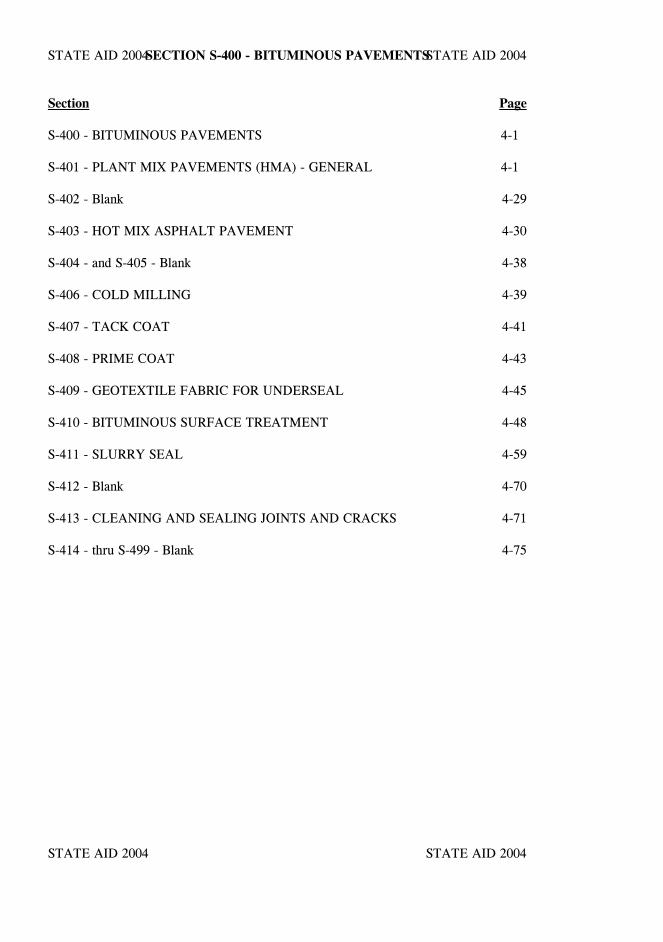
STATE AID 2004 STATE AID 2004
STATE AID 2004 STATE AID 2004
SECTION S-400 - BITUMINOUS PAVEMENTS
Section Page
S-400 - BITUMINOUS PAVEMENTS 4-1
S-401 - PLANT MIX PAVEMENTS (HMA) - GENERAL 4-1
S-402 - Blank 4-29
S-403 - HOT MIX ASPHALT PAVEMENT 4-30
S-404 - and S-405 - Blank 4-38
S-406 - COLD MILLING 4-39
S-407 - TACK COAT 4-41
S-408 - PRIME COAT 4-43
S-409 - GEOTEXTILE FABRIC FOR UNDERSEAL 4-45
S-410 - BITUMINOUS SURFACE TREATMENT 4-48
S-411 - SLURRY SEAL 4-59
S-412 - Blank 4-70
S-413 - CLEANING AND SEALING JOINTS AND CRACKS 4-71
S-414 - thru S-499 - Blank 4-75

STATE AID 2004 STATE AID 2004
STATE AID 2004 STATE AID 2004
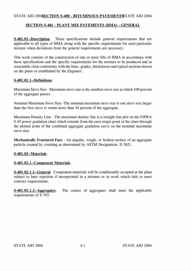
STATE AID 2004 STATE AID 2004
STATE AID 2004 STATE AID 20044-1
SECTION S-400 - BITUMINOUS PAVEMENTS
SECTION S-401 - PLANT MIX PAVEMENTS (HMA) - GENERAL
S-401.01--Description. These specifications include general requirements that areapplicable to all types of HMA along with the specific requirements for each particularmixture when deviations from the general requirements are necessary.
This work consists of the construction of one or more lifts of HMA in accordance withthese specifications and the specific requirements for the mixture to be produced and inreasonably close conformity with the lines, grades, thicknesses and typical sections shownon the plans or established by the Engineer.
S-401.01.1--Definitions.
Maximum Sieve Size - Maximum sieve size is the smallest sieve size at which 100 percentof the aggregate passes.
Nominal Maximum Sieve Size -The nominal maximum sieve size is one sieve size largerthan the first sieve to retain more than 10 percent of the aggregate.
Maximum Density Line - The maximum density line is a straight line plot on the FHWA0.45 power gradation chart which extends from the zero origin point of the chart throughthe plotted point of the combined aggregate gradation curve on the nominal maximumsieve size.
Mechanically Fractured Face - An angular, rough, or broken surface of an aggregateparticle created by crushing as determined by ASTM Designation: D 5821.
S-401.02--Materials.
S-401.02.1--Component Materials.
S-401.02.1.1--General. Component materials will be conditionally accepted at the plantsubject to later rejection if incorporated in a mixture or in work which fails to meetcontract requirements.
S-401.02.1.2--Aggregates. The source of aggregates shall meet the applicablerequirements of S-703.
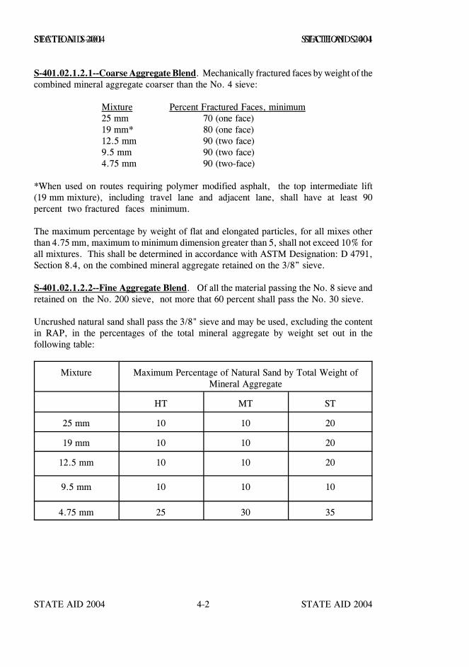
STATE AID 2004 STATE AID 2004
STATE AID 2004 STATE AID 20044-2
SECTION S-401 SECTION S-401
S-401.02.1.2.1--Coarse Aggregate Blend. Mechanically fractured faces by weight of thecombined mineral aggregate coarser than the No. 4 sieve:
Mixture Percent Fractured Faces, minimum25 mm 70 (one face)19 mm* 80 (one face)12.5 mm 90 (two face)9.5 mm 90 (two face)4.75 mm 90 (two-face)
*When used on routes requiring polymer modified asphalt, the top intermediate lift(19 mm mixture), including travel lane and adjacent lane, shall have at least 90percent two fractured faces minimum.
The maximum percentage by weight of flat and elongated particles, for all mixes otherthan 4.75 mm, maximum to minimum dimension greater than 5, shall not exceed 10% forall mixtures. This shall be determined in accordance with ASTM Designation: D 4791,Section 8.4, on the combined mineral aggregate retained on the 3/8” sieve.
S-401.02.1.2.2--Fine Aggregate Blend. Of all the material passing the No. 8 sieve andretained on the No. 200 sieve, not more that 60 percent shall pass the No. 30 sieve.
Uncrushed natural sand shall pass the 3/8" sieve and may be used, excluding the contentin RAP, in the percentages of the total mineral aggregate by weight set out in thefollowing table:
Mixture Maximum Percentage of Natural Sand by Total Weight ofMineral Aggregate
HT MT ST
25 mm 10 10 20
19 mm 10 10 20
12.5 mm 10 10 20
9.5 mm 10 10 10
4.75 mm 25 30 35
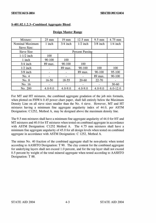
STATE AID 2004 STATE AID 2004
STATE AID 2004 STATE AID 20044-3
SECTION S-401 SECTION S-401
S-401.02.1.2.3--Combined Aggregate Blend.
Design Master Range
Mixture: 25 mm 19 mm 12.5 mm 9.5 mm 4.75 mmNominal Maximum
Sieve Size:1 inch 3/4 inch 1/2 inch 3/8 inch 1/4 inch
Sieve Size Percent Passing1-1/2 inch 100
1 inch 90-100 1003/4 inch 89 max. 90-100 1001/2 inch - 89 max. 90-100 100 1003/8 inch - - 89 max. 90-100 95-100No. 4 - - - 89 max. 90-100No. 8 16-50 18-55 20-60 22-70 -No. 16 - - - - 30-60No. 200 4.0-9.0 4.0-9.0 4.0-9.0 4.0-9.0 6.0-12.0
For MT and HT mixtures, the combined aggregate gradation of the job mix formula,when plotted on FHWA 0.45 power chart paper, shall fall entirely below the MaximumDensity Line on all sieve sizes smaller than the No. 4 sieve. However, MT and HTmixtures having a minimum fine aggregate angularity index of 44.0, per ASTMDesignation: C1252, Method A, may be designed above the maximum density line.
The 9.5 mm mixtures shall have a minimum fine aggregate angularity of 44.0 for HT andMT mixtures and 40.0 for ST mixtures when tested on combined aggregate in accordancewith ASTM Designation: C1252 Method A. The 4.75 mm mixtures shall have aminimum fine aggregate angularity of 45.0 for all design levels when tested on combinedaggregate in accordance with ASTM Designation: C 1252, Method A.
The minus No. 40 fraction of the combined aggregate shall be non-plastic when testedaccording to AASHTO Designation: T 90. The clay content for the combined aggregatefor underlying layers shall not exceed 1.0 percent, and for the top layer shall not exceed0.5 percent by weight of the total mineral aggregate when tested according to AASHTODesignation: T 88.
STATE AID 2004 STATE AID 2004
STATE AID 2004 STATE AID 20044-4
SECTION S-401 SECTION S-401
S-401.02.1.3--Bituminous–Materials. Bituminous materials shall meet the applicablerequirements of Section S-702 for the grade specified.
Tack coat shall be the same neat grade asphalt cement used in the mixture being placedor those materials specified for tack coat in Table 410-A. Emulsified asphalt shall not bediluted without approval of the Engineer.
S-401.02.1.4--Blank.
S-401.02.1.5--Hydrated Lime. Hydrated lime shall meet the requirements of S-714.03.2for lime used in soil stabilization.
S-401.02.1.6--Asphalt Admixtures. Additives for liquid asphalt, when required orpermitted, shall meet the requirements of S-702.08.
S-401.02.1.7--Polymers. Polymers for use in polymer modified HMA pavements shallmeet the requirements of S-702.08.3.
S-401.02.2-- Blank.
S-401.02.3--Composition of Mixtures.
S-401.02.3.1--General. Unless otherwise specified or permitted, the HMA shall consistof a mixture of asphalt, aggregate, hydrated lime and, when required or necessary toobtain desired properties, antistripping agent and/or other materials.
The total amount of crushed limestone aggregate for mixtures, excluding 4.75 mmmixtures, when used in the top lift, shall not exceed 50 percent of the total combinedaggregate by weight.
Hydrated lime shall be used in all HMA at the rate of one percent (1%) by weight of thetotal dry aggregate including aggregate in RAP, if used. The aggregate, prior to theaddition of the hydrated lime, shall contain sufficient surface moisture. If necessary, theContractor shall add moisture to the aggregate according to the procedures set out inS-401.03.2.1.2.
STATE AID 2004 STATE AID 2004
STATE AID 2004 STATE AID 20044-5
SECTION S-401 SECTION S-401
The Contractor shall obtain a shipping ticket for each shipment of hydrated lime. TheContractor shall provide the Engineer and MDOT District Materials Engineer or otherapproved Testing Laboratory with a copy of each shipping ticket from the supplier,including the date, time and weight of hydrated lime shipped and used in hot mix asphaltproduction. An amount equal to twenty-five percent (25%) of the total value of HMAitems performed during the initial estimate period in which the Contractor fails to submit the hydrated lime shipping tickets, asrequired, will be withheld from the Contractor's earned work. Non-conformance withthis specification for successive estimate period(s) will result in the total value (100%) ofHMA items performed during this period(s) being withheld from the Contractor's earnedwork. Monies withheld for this non-conformance will be released for payment on thenext monthly estimate following the date the submittal of hydrated lime shipping ticketsto the Engineer is brought back into compliance with this specification.
Mixtures will require the addition of an antistripping agent when the Tensile StrengthRatio (MT-63) and/or the Boiling Water Test (MT-59) fail to meet the following criteria.
Tensile Strength Ratio (TSR - MT-63)Wet Strength / Dry Strength 85 percent minimumInterior Face Coating 95 percent minimum
Boiling Water Test (MT-59)Particle Coating 95 percent minimum
Reclaimed asphalt pavement (RAP) materials may be used in the production of HMA inthe percentages of the total mix by weight set out in the following table:
HMA Mixture Maximum percent RAPby total weight of mix
4.75 mm 09.5 mm 1512.5 mm Top Lift 1512.5 mm Underlying Lift 3019 mm 3025 mm 30
During HMA production, the RAP shall pass through a maximum 2-inch square sievelocated in the HMA plant after the RAP cold feed bin and prior to the RAP weighingsystem.
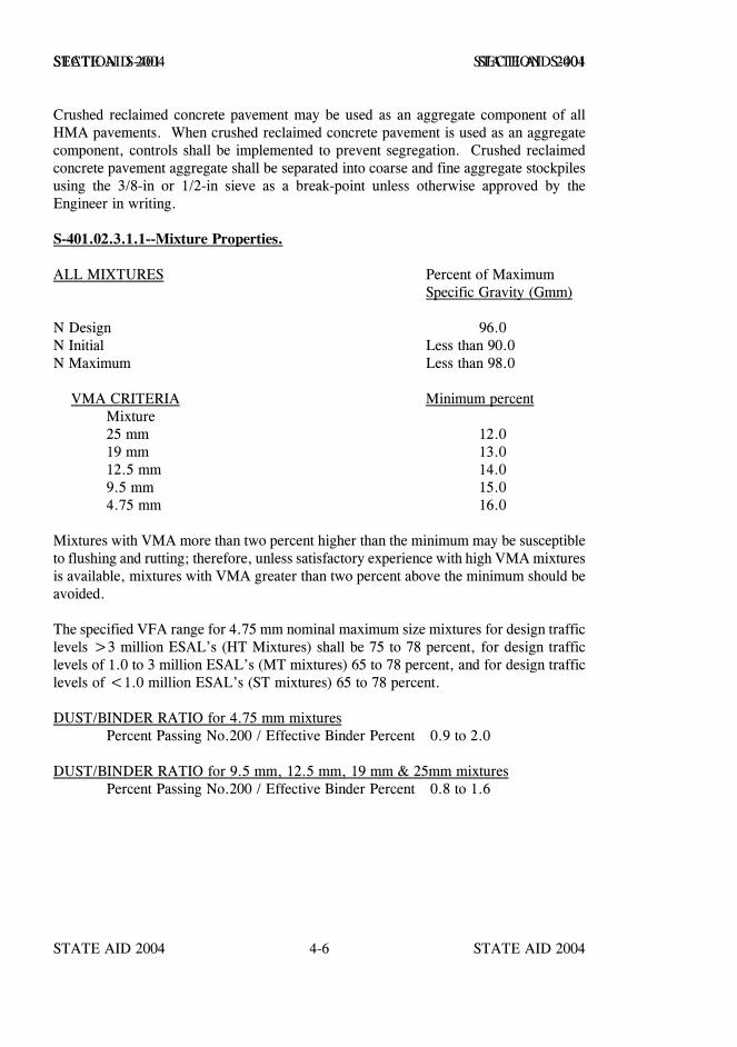
STATE AID 2004 STATE AID 2004
STATE AID 2004 STATE AID 20044-6
SECTION S-401 SECTION S-401
Crushed reclaimed concrete pavement may be used as an aggregate component of allHMA pavements. When crushed reclaimed concrete pavement is used as an aggregatecomponent, controls shall be implemented to prevent segregation. Crushed reclaimedconcrete pavement aggregate shall be separated into coarse and fine aggregate stockpilesusing the 3/8-in or 1/2-in sieve as a break-point unless otherwise approved by theEngineer in writing.
S-401.02.3.1.1--Mixture Properties.
ALL MIXTURES Percent of MaximumSpecific Gravity (Gmm)
N Design 96.0N Initial Less than 90.0N Maximum Less than 98.0
VMA CRITERIA Minimum percentMixture25 mm 12.019 mm 13.012.5 mm 14.09.5 mm 15.04.75 mm 16.0
Mixtures with VMA more than two percent higher than the minimum may be susceptibleto flushing and rutting; therefore, unless satisfactory experience with high VMA mixturesis available, mixtures with VMA greater than two percent above the minimum should beavoided.
The specified VFA range for 4.75 mm nominal maximum size mixtures for design trafficlevels >3 million ESAL’s (HT Mixtures) shall be 75 to 78 percent, for design trafficlevels of 1.0 to 3 million ESAL’s (MT mixtures) 65 to 78 percent, and for design trafficlevels of <1.0 million ESAL’s (ST mixtures) 65 to 78 percent.
DUST/BINDER RATIO for 4.75 mm mixturesPercent Passing No.200 / Effective Binder Percent 0.9 to 2.0
DUST/BINDER RATIO for 9.5 mm, 12.5 mm, 19 mm & 25mm mixturesPercent Passing No.200 / Effective Binder Percent 0.8 to 1.6
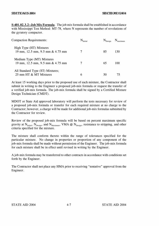
STATE AID 2004 STATE AID 2004
STATE AID 2004 STATE AID 20044-7
SECTION S-401 SECTION S-401
S-401.02.3.2--Job Mix Formula. The job mix formula shall be established in accordancewith Mississippi Test Method: MT-78, where N represents the number of revolutions ofthe gyratory compactor.
Compaction Requirements: NInitial NDesign Nmaximum
High Type (HT) Mixtures 19 mm, 12.5 mm, 9.5 mm & 4.75 mm 7 85 130
Medium Type (MT) Mixtures 19 mm, 12.5 mm, 9.5 mm & 4.75 mm 7 65 100
All Standard Type (ST) Mixtures; 25 mm HT & MT Mixtures 6 50 75
At least 15 working days prior to the proposed use of each mixture, the Contractor shallsubmit in writing to the Engineer a proposed job-mix formula or request the transfer ofa verified job-mix formula. The job-mix formula shall be signed by a Certified MixtureDesign Technician (CMDT).
MDOT or State Aid approved laboratory will perform the tests necessary for review ofa proposed job-mix formula or transfer for each required mixture at no charge to theContractor; however, a charge will be made for additional job-mix formulas submitted bythe Contractor for review.
Review of the proposed job-mix formula will be based on percent maximum specificgravity at NInitial, NDesign, and NMaximum, VMA @ NDesign, resistance to stripping, and othercriteria specified for the mixture.
The mixture shall conform thereto within the range of tolerances specified for theparticular mixture. No change in properties or proportion of any component of thejob-mix formula shall be made without permission of the Engineer. The job-mix formulafor each mixture shall be in effect until revised in writing by the Engineer.
A job-mix formula may be transferred to other contracts in accordance with conditions setforth by the Engineer.
The Contractor shall not place any HMA prior to receiving “tentative” approval from theEngineer.
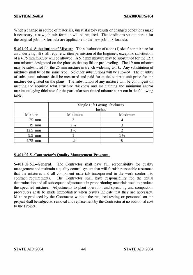
STATE AID 2004 STATE AID 2004
STATE AID 2004 STATE AID 20044-8
SECTION S-401 SECTION S-401
When a change in source of materials, unsatisfactory results or changed conditions makeit necessary, a new job-mix formula will be required. The conditions set out herein forthe original job-mix formula are applicable to the new job-mix formula.
S-401.02.4--Substitution of Mixture. The substitution of a one (1) size finer mixture foran underlying lift shall require written permission of the Engineer, except no substitutionof a 4.75 mm mixture will be allowed. A 9.5 mm mixture may be substituted for the 12.5mm mixture designated on the plans as the top lift or pre-leveling. The 19 mm mixturemay be substituted for the 25 mm mixture in trench widening work. Any substitution ofmixtures shall be of the same type. No other substitutions will be allowed. The quantityof substituted mixture shall be measured and paid for at the contract unit price for themixture designated on the plans. The substitution of any mixture will be contingent onmeeting the required total structure thickness and maintaining the minimum and/ormaximum laying thickness for the particular substituted mixture as set out in the followingtable.
Single Lift Laying ThicknessInches
Mixture Minimum Maximum25 mm 3 419 mm 2 ¼ 3
12.5 mm 1 ½ 29.5 mm 1 1 ½
4.75 mm ½ ¾
S-401.02.5--Contractor’s Quality Management Program.
S-401.02.5.1--General. The Contractor shall have full responsibility for qualitymanagement and maintain a quality control system that will furnish reasonable assurancethat the mixtures and all component materials incorporated in the work conform tocontract requirements. The Contractor shall have responsibility for the initialdetermination and all subsequent adjustments in proportioning materials used to producethe specified mixture. Adjustments to plant operation and spreading and compactionprocedures shall be made immediately when results indicate that they are necessary.Mixture produced by the Contractor without the required testing or personnel on theproject shall be subject to removal and replacement by the Contractor at no additional costto the Project.
STATE AID 2004 STATE AID 2004
STATE AID 2004 STATE AID 20044-9
SECTION S-401 SECTION S-401
S-401.02.5.2--Personnel Requirements. The Contractor shall provide at least oneCertified Asphalt Technician-I (CAT-I) full-time at each plant site used to furnish materialto the project. Sampling shall be conducted by a certified technician or by plant personnelunder the direct observation of a certified technician. All testing, data analysis and dataposting will be performed by the CAT-I or by an assistant under the direct supervision ofthe CAT-I. The Contractor shall have a Certified Asphalt Technician-II (CAT-II)available to make any necessary process adjustments. Technician certification shall be inaccordance with MDOT SOP TMD-22-10-00-000, MDOT HMA Technician CertificationProgram. An organizational chart, including names, telephone numbers and currentcertification, of all those responsible for the quality control program shall be posted in thecontractor’s laboratory while the asphaltic paving work is in progress.
S-401.02.5.3--Testing Requirements. As a minimum, the Contractor’s qualitymanagement program shall include the following.
(a) Bituminous Material. Provide Engineer with samples in sealed onequart metal containers at the required frequency according to currentState Aid Standard Operating Procedures (SOP).
(b) Mechanically Fractured Face. Determine mechanically fractured facecontent of aggregates retained on the No. 4 sieve, at a minimum of onetest per day of production.
(c) Mixture Gradation. Conduct extraction tests for gradationdetermination on the mixture. Sample according to the frequency inparagraph (i) and test according to Mississippi Test Method MT-31.
(d) Total Voids and VMA. Determine total voids and Voids in MineralAggregate (VMA) at N Design, from the results of bulk specific gravitytests on laboratory compacted specimens. Sample according to thesampling frequency in paragraph (i), and test according to the latestedition of MDOT’s field Manual for HMA.
(e) Asphalt Content. Sample according to the sampling frequency inparagraph (i). Determine the asphalt content using one of the followingprocedures. (1) Nuclear gauge. (Mississippi Test Method MT-6)(2) Incinerator oven per AASHTO Designation: T 308, Method A.
STATE AID 2004 STATE AID 2004
STATE AID 2004 STATE AID 20044-10
SECTION S-401 SECTION S-401
(f) Stripping Tests. Conduct a minimum of one stripping test at thebeginning of each job-mix production and thereafter, at least once pereach two weeks of production according to Mississippi Test Method:MT-63 and one stripping test per day of production according toMississippi Test Method: MT-59. Should either the TSR (MT-63) orthe boiling water (MT-59) stripping tests fail, a new antistrip additiveor rate shall be established or other changes made immediately that willresult in a mixture which conforms to the specifications; otherwise,production shall be suspended until corrections are made.
(g) Density Tests. For 25 mm, 19.5 mm, 12.5 mm & 9.5 mm mixtures,conduct density tests as necessary to control and maintain requiredcompaction according to Mississippi Test Method: MT-16, Method C(nuclear gauge), or AASHTO Designation: T 166. Note - The nucleargauge may be correlated, at the Contractor’s option, with the averageof a minimum of five pavement sample densities. For 4.75 mmmixtures, conduct density tests as necessary to control and maintainrequired compaction according to AASHTO Designation: T 166.
(h) Quality Control Charts. Plot the individual test data, the average of thelast four tests and the control limits for the following items as aminimum:
Mixture Gradation (Percent Passing) Sieves:1/2-in, 3/8-in, No. 8, No. 16, No. 30 and No. 200.
Asphalt Content, PercentMaximum Specific Gravity, Gmm
Total Voids @ NDesign, Percent VMA @ NDesign, Percent
NOTE: For 4.75 mm mixtures, Quality Control Charts for mixturegradation are not required on the No. 8 and No. 30 sieves. For 4.75mm mixtures, as a minimum, Quality Control Charts for mixturegradation shall be kept on the 3/8-in, No. 16 and No. 200 sieves. Forall mixtures other than 4.75 mm, Quality Control Charts for mixturegradation are not required on the No. 16 sieve.
Keep charts up-to-date and posted in a readily observable location.Charts may be kept on a computer, however, the charts shall be printedout a minimum of once each production day and displayed in thelaboratory. Note any process changes or adjustments on the Air Voidschart.
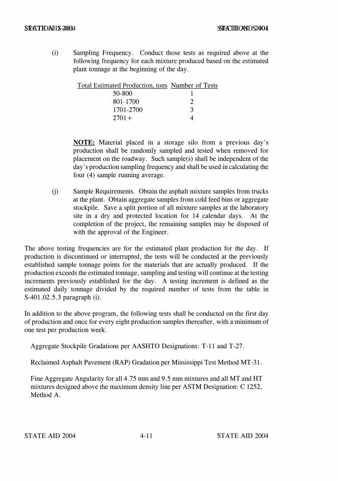
STATE AID 2004 STATE AID 2004
STATE AID 2004 STATE AID 20044-11
SECTION S-401 SECTION S-401
(i) Sampling Frequency. Conduct those tests as required above at thefollowing frequency for each mixture produced based on the estimatedplant tonnage at the beginning of the day.
Total Estimated Production, tons Number of Tests50-800 1801-1700 21701-2700 32701+ 4
NOTE: Material placed in a storage silo from a previous day'sproduction shall be randomly sampled and tested when removed forplacement on the roadway. Such sample(s) shall be independent of theday's production sampling frequency and shall be used in calculating thefour (4) sample running average.
(j) Sample Requirements. Obtain the asphalt mixture samples from trucksat the plant. Obtain aggregate samples from cold feed bins or aggregatestockpile. Save a split portion of all mixture samples at the laboratorysite in a dry and protected location for 14 calendar days. At thecompletion of the project, the remaining samples may be disposed ofwith the approval of the Engineer.
The above testing frequencies are for the estimated plant production for the day. Ifproduction is discontinued or interrupted, the tests will be conducted at the previouslyestablished sample tonnage points for the materials that are actually produced. If theproduction exceeds the estimated tonnage, sampling and testing will continue at the testingincrements previously established for the day. A testing increment is defined as theestimated daily tonnage divided by the required number of tests from the table inS-401.02.5.3 paragraph (i).
In addition to the above program, the following tests shall be conducted on the first dayof production and once for every eight production samples thereafter, with a minimum ofone test per production week.
Aggregate Stockpile Gradations per AASHTO Designations: T-11 and T-27.
Reclaimed Asphalt Pavement (RAP) Gradation per Mississippi Test Method MT-31.
Fine Aggregate Angularity for all 4.75 mm and 9.5 mm mixtures and all MT and HTmixtures designed above the maximum density line per ASTM Designation: C 1252,Method A.
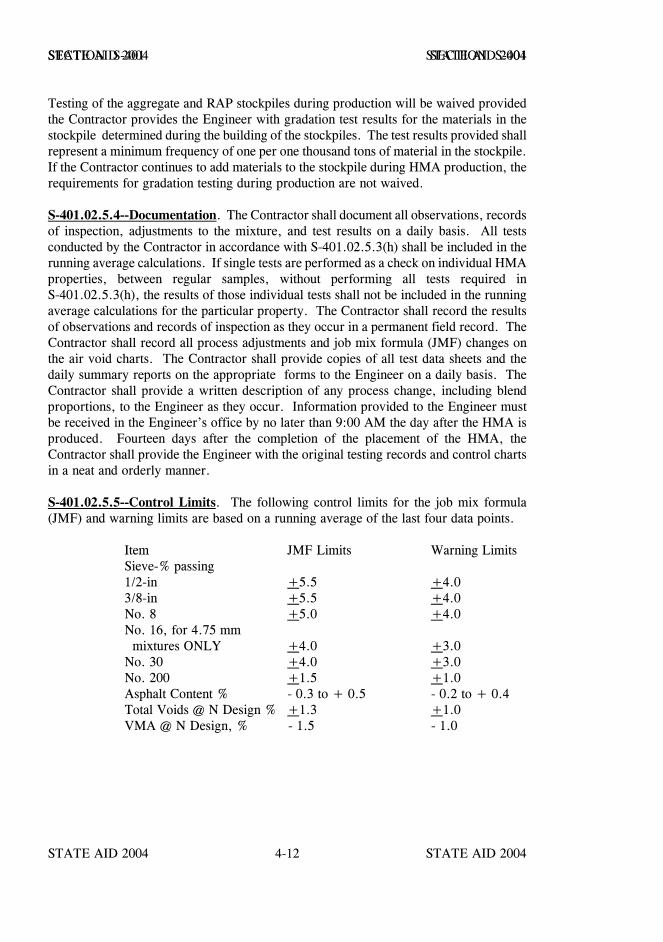
STATE AID 2004 STATE AID 2004
STATE AID 2004 STATE AID 20044-12
SECTION S-401 SECTION S-401
Testing of the aggregate and RAP stockpiles during production will be waived providedthe Contractor provides the Engineer with gradation test results for the materials in thestockpile determined during the building of the stockpiles. The test results provided shallrepresent a minimum frequency of one per one thousand tons of material in the stockpile.If the Contractor continues to add materials to the stockpile during HMA production, therequirements for gradation testing during production are not waived.
S-401.02.5.4--Documentation. The Contractor shall document all observations, recordsof inspection, adjustments to the mixture, and test results on a daily basis. All testsconducted by the Contractor in accordance with S-401.02.5.3(h) shall be included in therunning average calculations. If single tests are performed as a check on individual HMAproperties, between regular samples, without performing all tests required inS-401.02.5.3(h), the results of those individual tests shall not be included in the runningaverage calculations for the particular property. The Contractor shall record the resultsof observations and records of inspection as they occur in a permanent field record. TheContractor shall record all process adjustments and job mix formula (JMF) changes onthe air void charts. The Contractor shall provide copies of all test data sheets and thedaily summary reports on the appropriate forms to the Engineer on a daily basis. TheContractor shall provide a written description of any process change, including blendproportions, to the Engineer as they occur. Information provided to the Engineer mustbe received in the Engineer’s office by no later than 9:00 AM the day after the HMA isproduced. Fourteen days after the completion of the placement of the HMA, theContractor shall provide the Engineer with the original testing records and control chartsin a neat and orderly manner.
S-401.02.5.5--Control Limits. The following control limits for the job mix formula(JMF) and warning limits are based on a running average of the last four data points.
Item JMF Limits Warning LimitsSieve-% passing1/2-in +5.5 +4.03/8-in +5.5 +4.0No. 8 +5.0 +4.0No. 16, for 4.75 mm mixtures ONLY +4.0 +3.0No. 30 +4.0 +3.0No. 200 +1.5 +1.0Asphalt Content % - 0.3 to + 0.5 - 0.2 to + 0.4Total Voids @ N Design % +1.3 +1.0VMA @ N Design, % - 1.5 - 1.0
STATE AID 2004 STATE AID 2004
STATE AID 2004 STATE AID 20044-13
SECTION S-401 SECTION S-401
S-401.02.5.6--Warning Bands. Warning bands are defined as the area between the JMFlimits and the warning limits.
S-401.02.5.7--Job Mix Formula Adjustments. A request for a JMF adjustment signedby a CAT-II may be made to the Engineer by the Contractor. Submit sufficient testingdata with the request to justify the change. The requested change will be reviewed by theEngineer. If current production values meet the mixture design requirements, a revisedJMF will be issued. Adjustments to the JMF shall conform to the latest edition ofMDOT’s Field Manual for HMA. Adjustments to JMF limits to conform to actualproduction shall not exceed the tolerance specified for the JMF limits. Regardless of suchtolerances, any adjusted JMF gradation shall be within the design master range for themixture specified. The JMF asphalt content may only be reduced if the production VMAmeets or exceeds the minimum design VMA requirements for the mixture being produced.
S-401.02.5.8--Action and Adjustments. Based on the process control test results for anyproperty in question, the following actions shall be taken or adjustments made whenappropriate:
(a) When the running average trends toward the warning limits, theContractor shall consider taking corrective action. The correctiveaction, if any, shall be documented. All tests shall be part of thecontract files and shall be included in the running average calculations.
(b) The Contractor shall notify the Engineer whenever the running averageexceeds the warning limits.
(c) If two consecutive running averages exceed the warning limit, theContractor shall stop production and make adjustments. Productionshall only be restarted after notifying the Engineer of the adjustmentsmade.
(d) If the adjustments made under (c) improve the process such that therunning average after four additional tests is within the warning limits,the Contractor may continue production with no reduction in payment.
(e) If the adjustment made under (c) does not improve the process and therunning average after four additional tests stays in the warning band, themixture will be considered unsatisfactory. Reduced payment forunsatisfactory mixtures will be applied starting from the stop point tothe point when the running average is back within the warning limits inaccordance with S-401.02.6.3.
STATE AID 2004 STATE AID 2004
STATE AID 2004 STATE AID 20044-14
SECTION S-401 SECTION S-401
(f) Failure to stop production and make adjustments when required shallsubject all mixture produced from the stop point to the point when therunning average is back within the warning limits to be consideredunsatisfactory. Reduced payment for unsatisfactory mixtures will beapplied in accordance with S-401.02.6.3.
(g) If the running average exceeds the JMF limits, the Contractor shall stopproduction and make adjustments. Production shall only be restartedafter notifying the Engineer of the adjustments made.
(h) All materials for which the running average exceeds the JMF limits willbe considered unacceptable and shall be removed and replaced by theContractor at no additional cost to the Project. The Engineer willdetermine the quantity of material to be replaced based on a review ofthe individual testing data which make up the running average inquestion and an inspection of the completed pavement. If the Engineerdecides to leave the mixture in place because of special circumstances,the quantity of mixture, as defined above, will be paid for in accordancewith S-401.02.6.3.
(i) Single test results shall be compared to twice the warning and JMFlimits. If the test results verified by a State Aid approved Laboratoryor MDOT (within allowable differences in S-401.02.6.2) exceed theselimits, the pay factor provided in S-401.02.6.3 will apply for thequantity of material represented by the test(s). Single test limits will beused for the acceptance of projects when insufficient tonnage is producedto require four (4) Contractor’s tests.
(j) The above corrective action will also apply for a mixture when theContractor’s testing data has been proven incorrect. The Contractor’sdata will be considered incorrect when; 1) the Contractor’s tests and theEngineer’s tests do not agree within the allowable differences given inS-401.02.6.2 and the difference can not be resolved, or 2) theEngineer’s tests indicates that production is outside the JMF limits andthe results have been verified by MDOT or other State Aid approvedLaboratory. The Engineer’s data will be used in place of theContractor’s data to determine the appropriate pay factor.
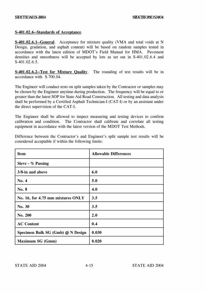
STATE AID 2004 STATE AID 2004
STATE AID 2004 STATE AID 20044-15
SECTION S-401 SECTION S-401
S-401.02.6--Standards of Acceptance.
S-401.02.6.1--General. Acceptance for mixture quality (VMA and total voids at NDesign, gradation, and asphalt content) will be based on random samples tested inaccordance with the latest edition of MDOT’s Field Manual for HMA. Pavementdensities and smoothness will be accepted by lots as set out in S-401.02.6.4 andS-401.02.6.5.
S-401.02.6.2--Test for Mixture Quality. The rounding of test results will be inaccordance with S-700.04.
The Engineer will conduct tests on split samples taken by the Contractor or samples maybe chosen by the Engineer anytime during production. The frequency will be equal to orgreater than the latest SOP for State Aid Road Construction. All testing and data analysisshall be performed by a Certified Asphalt Technician-I (CAT-I) or by an assistant underthe direct supervision of the CAT-I.
The Engineer shall be allowed to inspect measuring and testing devices to confirmcalibration and condition. The Contractor shall calibrate and correlate all testingequipment in accordance with the latest version of the MDOT Test Methods.
Difference between the Contractor’s and Engineer’s split sample test results will beconsidered acceptable if within the following limits:
Item Allowable Differences
Sieve - % Passing
3/8-in and above 6.0
No. 4 5.0
No. 8 4.0
No. 16, for 4.75 mm mixtures ONLY 3.5
No. 30 3.5
No. 200 2.0
AC Content 0.4
Specimen Bulk SG (Gmb) @ N Design 0.030
Maximum SG (Gmm) 0.020

STATE AID 2004 STATE AID 2004
STATE AID 2004 STATE AID 20044-16
SECTION S-401 SECTION S-401
In the event comparison test results are outside the above allowable differences, theEngineer will investigate the reason immediately. The Engineer’s investigation mayinclude testing of the remaining split samples, review and observation of the Contractor’stesting procedures and equipment and a comparison of split sample test results by thecontractor quality control laboratory, State Aid approved laboratory or MDOT MaterialsDivision. In the event reasons for the differences cannot be determined, the Engineer’sresults will be used for the quality control data and the appropriate payment for themixture and asphalt will be based on the procedures specified in S-401.02.5.8.
The Engineer may witness the sampling and testing being performed by the contractor.The Engineer, both verbally and in writing, will promptly notify the Contractor of anyobserved deficiencies. When differences exist between the contractor and the Engineerwhich cannot be resolved, a decision will be made by the State Aid Engineer, acting asthe referee, and will in writing promptly notify the Contractor. If the deficiencies are notcorrected, the Engineer will stop production until corrective action is taken.
S-401.02.6.3--Acceptance Procedure for Mixture Quality. All obviously defectivematerial or mixture will be subject to rejection by the Engineer. Such defective materialor mixture shall not be incorporated into the finished work. If the defective material hasalready been placed in the work, the material shall be removed and replaced at noadditional cost to the Project.
The Engineer will base final acceptance of the asphalt mixture production on the resultsof the Contractor's testing for total voids and VMA @ NDesign, gradation, and asphalt contentas verified by the Engineer in the manner hereinbefore described and the uniformity andcondition of the completed pavement. Areas of pavement that exhibit non-uniformity orfailures, materials or construction related, such as but not limited to segregation, bleeding,shoving, rutting over 1/8", raveling, slippage, or cracking will not be accepted. Such areaswill be removed and replaced at no additional cost to the Project.
Bituminous mixture placed prior to correction for deficiencies in VMA and total voids @NDesign, gradation, or asphalt content, as required in S-401.02.5.8 and determined by theEngineer satisfactory to remain in place will be paid for in accordance with the following payfactors times the contract unit price per ton.
Pay Factor for Mixture Quality *
Item Produced in WarningBands
Produced Outside JMF Limits,Allowed to Remain in Place
Gradation 0.90 0.75Asphalt Content 0.85 0.75Total Voids @ NDesign 0.70 0.50VMA @ NDesign 0.90 0.75
*The minimum single payment will apply.

STATE AID 2004 STATE AID 2004
STATE AID 2004 STATE AID 20044-17
SECTION S-401 SECTION S-401
S-401.02.6.4--Acceptance Procedure for Density. Each completed lift will be accepted withrespect to compaction on a lot basis from density tests performed by the Engineer. For normalproduction days, divide the production into approximately equal lots as shown in the followingtable. When cores are being used for the compaction evaluation, randomly obtain one corefrom each lot. When the nuclear density gauge is being used for compaction evaluation, obtaintwo random readings from each lot and average the results. Additional tests may be requiredby the Engineer to determine acceptance of work appearing deficient. The Contractor shallfurnish and maintain traffic control for all compaction evaluations, including coring, requiredin satisfying specified density requirements.
Lot Determination
Daily Production - Tons Number of Lots
0-300 1
301-600 2
601-1000 3
1001-1500 4
1501-2100 5
2101-2800 6
2801+ 7
S-401.02.6.4.1--Roadway Density. The density requirement for each completed lift on a lotto lot basis from density tests performed by the Engineer shall be as follows:
1. For all single lift overlays, with or without leveling and/or milling, the requiredlot density shall be 92.0 percent of maximum density.
2. For all multiple lift overlays of two (2) or more lifts excluding leveling lifts, therequired lot density of the bottom lift shall be 92. 0 percent of maximum density.The required lot density for all subsequent lifts shall be 93.0 percent ofmaximum density.
3. For all pavements on new construction, the required lot density for all lifts shallbe 93.0 percent of maximum density.
STATE AID 2004 STATE AID 2004
STATE AID 2004 STATE AID 20044-18
SECTION S-401 SECTION S-401
When it is determined that the density for a lot is below the required density (93.0 percent or92.0 percent) but not lower than 91.0 or 90.0 percent of maximum density, respectively, theContractor will have the right to remove and replace the lot(s) not meeting the specified densityrequirements in lieu of accepting reduced payment for the lot(s).
When it is determined that the density for a lot is above 96.0 percent, the Engineer shall notifythe Contractor who will make plant adjustments to resolve the problem.
When it is determined that the density for a lot is below 91.0 or 90.0 percent, respectively, thelot(s), or portions thereof shall be removed and replaced in accordance with Chapter 7 of thelatest edition of MDOT’s Field Manual for HMA at no additional cost to the Project. Acorrected lot will be retested for approval. No resampling will be performed when pavementsamples are used for determining density.
At any time the average daily compaction (the total of the percent compaction for the lotsproduced in one day divided by the total number of lots for the day) does not meet the requiredpercent compaction or more for two consecutive days, the Contractor shall notify the Engineerof proposed changes to the compactive effort. If the average daily compaction does not meetthe required percent compaction or more for a third consecutive day, the Contractor shall stopproduction until compaction procedures are established to meet the specified densityrequirements.
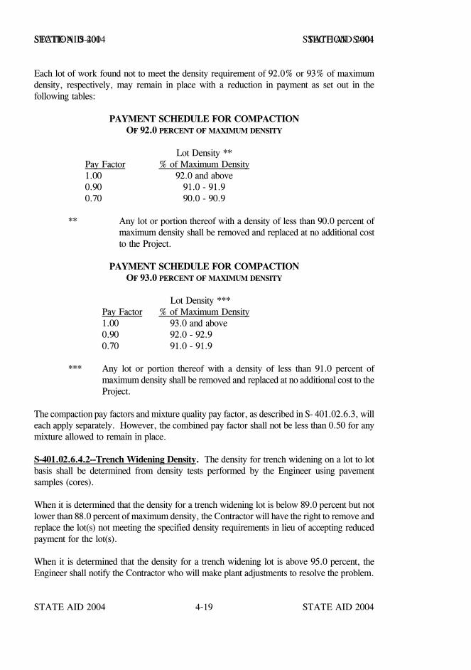
STATE AID 2004 STATE AID 2004
STATE AID 2004 STATE AID 20044-19
SECTION S-401 SECTION S-401
Each lot of work found not to meet the density requirement of 92.0% or 93% of maximumdensity, respectively, may remain in place with a reduction in payment as set out in thefollowing tables:
PAYMENT SCHEDULE FOR COMPACTIONOF 92.0 PERCENT OF MAXIMUM DENSITY
Lot Density **Pay Factor % of Maximum Density1.00 92.0 and above0.90 91.0 - 91.90.70 90.0 - 90.9
** Any lot or portion thereof with a density of less than 90.0 percent ofmaximum density shall be removed and replaced at no additional costto the Project.
PAYMENT SCHEDULE FOR COMPACTIONOF 93.0 PERCENT OF MAXIMUM DENSITY
Lot Density ***Pay Factor % of Maximum Density1.00 93.0 and above0.90 92.0 - 92.90.70 91.0 - 91.9
*** Any lot or portion thereof with a density of less than 91.0 percent ofmaximum density shall be removed and replaced at no additional cost to theProject.
The compaction pay factors and mixture quality pay factor, as described in S- 401.02.6.3, willeach apply separately. However, the combined pay factor shall not be less than 0.50 for anymixture allowed to remain in place.
S-401.02.6.4.2--Trench Widening Density. The density for trench widening on a lot to lotbasis shall be determined from density tests performed by the Engineer using pavementsamples (cores).
When it is determined that the density for a trench widening lot is below 89.0 percent but notlower than 88.0 percent of maximum density, the Contractor will have the right to remove andreplace the lot(s) not meeting the specified density requirements in lieu of accepting reducedpayment for the lot(s).
When it is determined that the density for a trench widening lot is above 95.0 percent, theEngineer shall notify the Contractor who will make plant adjustments to resolve the problem.

STATE AID 2004 STATE AID 2004
STATE AID 2004 STATE AID 20044-20
SECTION S-401 SECTION S-401
When it is determined that the density for a trench widening lot is below 88.0 percent, thelot(s), or portions thereof shall be removed and replaced in accordance with Chapter 7 of thelatest edition of MDOT’s Field Manual for HMA at no additional cost to the Project. Acorrected lot will be retested for approval. No resampling will be performed when pavementsamples are used for determining density.
At any time the daily compaction (the total of the percent compaction for the lots produced inone day divided by the total number of lots for the day) does not meet 89.0 percentcompaction or more for two consecutive days, the Contractor shall notify the Engineer ofproposed changes to the compactive effort. If the average daily compaction does not meet 89.0percent compaction or more for a third consecutive day, the Contractor shall stop productionuntil compaction procedures are established to meet the specified density requirement.
Each lot of trench widening work found not to meet the density requirement of 89.0 percentof maximum density may remain in place with a reduction in payment as set out in thefollowing table:
PAYMENT SCHEDULE FOR COMPACTIONTRENCH WIDENING WORK
Lot Density ***Pay Factor % of Maximum Density
1.00 89.0 and above0.50 88.0 - 88.9
*** Any lot or portion thereof with a density of less than 88.0 percent of maximum densityshall be removed and replaced at no additional cost to the Project.
The compaction pay factors and mixture quality pay factor, as described in S- 401.02.6.3, willeach apply separately. However, the combined pay factor shall not be less than 0.50 for anymixture allowed to remain in place.
S-401.02.6.5--Acceptance Procedure for Pavement Smoothness. When compaction iscompleted, the lift shall have a uniform surface and be in reasonably close conformity with theline, grade and cross section shown on the plans.
When required by the Engineer, and approved by the State Aid Engineer, the smoothness ofeach applicable lift will be determined by using a California profilograph to produce aprofilogram (profile trace) at each designated location. The surface shall be tested andcorrected to a smoothness index as described in MDOT Specifications.
STATE AID 2004 STATE AID 2004
STATE AID 2004 STATE AID 20044-21
SECTION S-401 SECTION S-401
S-401.02.6.7--Surface Correction. Corrective work to bumps shall consist of diamondgrinding in accordance with these specifications or methods approved by the Engineer. Allsurface areas corrected by grinding shall be sealed with a sealant approved by the Engineer.
S-401.02.6.7.1--Diamond Grinding. Grinding of asphalt surfaces shall consist of diamondgrinding the existing asphalt pavement surface to remove surface distortions to achieve thespecified surface smoothness requirements.
S-401.02.6.7.2--Equipment. The grinding equipment shall be a power driven, self-propelledmachine that is specifically designed to smooth and texture pavement surfaces with diamondblades. The effective wheel base of the machine shall not be less than 12.0 feet. It shall havea set of pivoting tandem bogey wheels at the front of the machine and the rear wheels shall bearranged to travel in the track of the fresh cut pavement. The center of the grinding head shallbe no further than 3.0 feet forward from the center of the back wheels.
The equipment shall be of a size that will cut or plane at least 2.0 feet wide. It shall also beof a shape and dimension that does not encroach on traffic movement outside of the work area.The equipment shall be capable of grinding the surface without causing spalls at joints, or otherlocations.
S-401.02.6.7.3--Construction. The construction operation shall be scheduled and proceed ina manner that produces a uniform finish surface. Grinding will be accomplished in a mannerto provide positive lateral drainage by maintaining a constant cross-slope between grindingextremities in each lane.
The operation shall result in pavement that conforms to the typical cross-section and therequirements specified in S-401.02.6.7.4. It is the intent of this specification that the surfacesmoothness characteristics be within the limits specified.
The Contractor shall establish positive means for removal of grinding residue. Solid residueshall be removed from pavement surfaces before it is blown by traffic action or wind. Residueshall not be permitted to flow across lanes used by public traffic or into gutters or drainagefacilities, but may be allowed to flow into adjacent ditches.
S-401.02.6.7.4--Finished Pavement Surface. The grinding process shall produce a pavementsurface that is smooth and uniform in appearance with a longitudinal line type texture. The linetype texture shall contain parallel longitudinal corrugations that present a narrow ridge corduroytype appearance. The peaks of the ridges shall not be more than 1/16 inch higher than thebottoms of the grooves.
The finished pavement surface will be measured for riding quality. The grinding shall producea riding surface which does not exceed either the specified profile index or the specified bumpand dip limit.
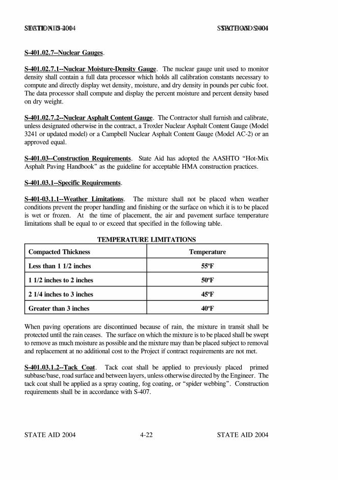
STATE AID 2004 STATE AID 2004
STATE AID 2004 STATE AID 20044-22
SECTION S-401 SECTION S-401
S-401.02.7--Nuclear Gauges.
S-401.02.7.1--Nuclear Moisture-Density Gauge. The nuclear gauge unit used to monitordensity shall contain a full data processor which holds all calibration constants necessary tocompute and directly display wet density, moisture, and dry density in pounds per cubic foot.The data processor shall compute and display the percent moisture and percent density basedon dry weight.
S-401.02.7.2--Nuclear Asphalt Content Gauge. The Contractor shall furnish and calibrate,unless designated otherwise in the contract, a Troxler Nuclear Asphalt Content Gauge (Model3241 or updated model) or a Campbell Nuclear Asphalt Content Gauge (Model AC-2) or anapproved equal.
S-401.03--Construction Requirements. State Aid has adopted the AASHTO “Hot-MixAsphalt Paving Handbook” as the guideline for acceptable HMA construction practices.
S-401.03.1--Specific Requirements.
S-401-03.1.1--Weather Limitations. The mixture shall not be placed when weatherconditions prevent the proper handling and finishing or the surface on which it is to be placedis wet or frozen. At the time of placement, the air and pavement surface temperaturelimitations shall be equal to or exceed that specified in the following table.
TEMPERATURE LIMITATIONS
Compacted Thickness Temperature
Less than 1 1/2 inches 55oF
1 1/2 inches to 2 inches 50oF
2 1/4 inches to 3 inches 45oF
Greater than 3 inches 40oF
When paving operations are discontinued because of rain, the mixture in transit shall beprotected until the rain ceases. The surface on which the mixture is to be placed shall be sweptto remove as much moisture as possible and the mixture may than be placed subject to removaland replacement at no additional cost to the Project if contract requirements are not met.
S-401.03.1.2--Tack Coat. Tack coat shall be applied to previously placed primedsubbase/base, road surface and between layers, unless otherwise directed by the Engineer. Thetack coat shall be applied as a spray coating, fog coating, or “spider webbing”. Constructionrequirements shall be in accordance with S-407.
STATE AID 2004 STATE AID 2004
STATE AID 2004 STATE AID 20044-23
SECTION S-401 SECTION S-401
S-401.03.1.3--Blank.
S-401.03.1.4--Density. The lot density for all dense graded pavement lifts, except as providedbelow for preleveling, wedging {less than fifty percent (50%) of width greater than minimumlift thickness}, ramp pads, irregular shoulder areas, median crossovers, turnouts, or other areaswhere the established rolling pattern cannot be performed, shall not be less than 92.0 percentof the maximum density based on AASHTO Designation: T209 for the day’s production. Ifa job-mix formula adjustment is made during the day which affects the maximum specificgravity, calculate a new average maximum density for the lot(s) placed after the change.
Pavement core samples obtained for determining density which have a thickness less than twotimes the maximum size aggregate permitted by the job-mix formula will not be used as arepresentative sample.
Preleveling, wedging {less than fifty percent (50%) of width greater than minimum liftthickness}, ramp pads, irregular shoulder areas, median crossovers, turnouts, and other areaswhere an established rolling pattern cannot be obtained shall be compacted to refusaldensification.
S-401.03.2--Bituminous Mixing Plants.
S-401.03.2.1--Plant Requirements.
S-401.03.2.1.1--Cold Aggregate Storage. The cold storage for hydrate lime shall be aseparate bulk storage bin with a vane feeder or other approved feeder system which can readilybe calibrated. The system shall provide a means for easy sampling of the hydrated limeadditive and verifying the quantity of lime dispensed. The feeder system shall require atotalizer.
The hydrated lime additive equipment shall be interlocked and synchronized with the cold feedcontrols to operate concurrently with the cold feed operation which will automatically adjustthe hydrated lime feed to variations in the cold aggregate feed. A positive signal system shallbe installed which will automatically shut the plant down when malfunctions cause an impropersupply of hydrated lime or water.
The plant shall not operate unless the entire hydrated lime system is functioning properly.
S-401.03.2.1.2--Cold Aggregate Feed. The hydrated lime shall be dispensed dry or as aslurry (1 part hydrated lime to 3 parts water) directly onto the composite aggregate betweenthe cold feed and the dryer.
STATE AID 2004 STATE AID 2004
STATE AID 2004 STATE AID 20044-24
SECTION S-401 SECTION S-401
When hydrated lime is introduced dry, a spray bar or other approved system capable ofspraying all aggregate with water shall be installed in order to maintain all aggregate at themoisture condition set out in S-401.02.3.1 prior to addition of the hydrated lime. An alternatesystem for spraying the coarse aggregate stockpiles may be allowed when approved by theEngineer. The approved equipment and methods shall consistently maintain the aggregate in a uniform, surface wet condition. Themoisture content of the aggregate-hydrated lime mixture, following spraying and mixing, shallbe introduced into the automatic moisture controls of the plant.
The aggregate-hydrated lime mixture shall be uniformly blended by some mechanical meanssuch as a motorized “on the belt” mixer or pug mill located between the cold feed and thedryer. Other mixing devices may be used subject to approval by the Engineer.
A maximum of forty five (45) percent of the total aggregate blend may be fed through anysingle cold feed bin. If the JMF calls for more than forty five (45) percent of a specificaggregate, that aggregate must be fed through two (2) or more separate cold feed
S-401.03.2.1.3--Dryer. The efficiency of drying aggregates shall be such that the moisturecontent of the top HMA mixture shall not exceed 0.50 percent by weight of the total mixture,and the moisture content of all the underlying mixtures shall not exceed 0.75 percent by weightof the total mixture being produced.
S-401-03.2.1.4--Blank.
S-401.03.2.1.5--Control of Bituminous Material and Antistripping Agent. Specifiedbituminous materials from different manufacturers or from different refineries of a singlemanufacturer shall not be mixed in the plant’s asphalt cement supply system storage tank andused in the work without prior written approval of the Engineer. Approval is contingent uponthe Engineer’s receipt of three copies of the manufacturer’s certified test report(s) from theContractor showing that the bituminous material blend conforms to the specifications.
A satisfactory method of weighing or metering shall be provided to ensure the specifiedquantity of bituminous material. Provisions shall be provided for checking the quantity or rateof flow. Weighing or metering devices shall be accurate within plus or minus one-half percent.
The antistripping agent shall be injected into the bituminous material immediately prior to themixing operation with an approved in-line injector system capable of being calibrated so as toensure the prescribed dosage.
An in-line spigot for sampling of asphalt shall be located between the asphalt storage tank andthe antistripping agent in-line injector.
STATE AID 2004 STATE AID 2004
STATE AID 2004 STATE AID 20044-25
SECTION S-401 SECTION S-401
S-401.03.2.1.6--Thermometric Equipment. An armored thermometer of adequate range andcalibrated in 5oF increments shall be fixed at a suitable location in the bituminous line near thecharging valve of the mixer unit.
The plant shall be equipped with an approved dial-scale, mercury-actuated thermometer,pyrometer or other approved thermometric instrument placed at the discharge chute of thedryer to measure the temperature of the material.
When the temperature control is unsatisfactory, the Engineer may require an approvedtemperature-recording apparatus for better regulation of the temperature.
S-401.03.2.1.7--Screens. A scalping screen shall be used.
S-401.03.2.1.8--Dust Collector. The plant shall be equipped with a dust collector constructedto waste or return collected material. When collected material is returned, it shall be returnedthrough a controlling device which will provide a uniform flow of material into the aggregatemixture.
S-401.03.2.1.9--Safety Requirements. A platform or other suitable device shall be providedso the Engineer will have access to the truck bodies for sampling and mixture temperature data.
S-401.03.2.1.10--Blank.
S-401.03.2.1.11--Truck Scales. The specifications, tolerances and regulations for commercialweighing and measuring devices as recommended by the National Bureau of Standards{National Institute of Standards and Technology (NIST) handbook 44} shall govern truck scalesused in the State of Mississippi, except weighing devices with a capacity of ten thousand(10,000) pounds or more used to weigh road construction materials (i.e. sand, gravel, asphalt,fill dirt, topsoil and concrete) shall have a tolerance of one-half of one percent (1/2 of 1%) inlieu of the requirements of Handbook 44 and shall be regulated by the Mississippi Departmentof Transportation.
Scales shall be checked and certified by a scale company certified in heavy truck weights bythe Mississippi Department of Agriculture and Commerce. In the case of scales used formeasurement of materials on Department of Transportation projects or State Aid projects,certification shall be performed in the presence of an authorized representative of MDOT ora copy of the certification may be furnished for scales that have been checked and certifiedwithin the last six months for use on other Department of Transportation or State Aid projectsand are still in the position where previously tested. Scales that have not been checked andcertified under NIST Handbook 44 guidelines, except for the herein modified tolerancesallowed, shall be so checked and certified prior to use for measurement of materials onDepartment of Transportation or State Aid projects. Tests shall be continued on six monthintervals with the test conducted in the presence of an authorized representative of MDOT.
STATE AID 2004 STATE AID 2004
STATE AID 2004 STATE AID 20044-26
SECTION S-401 SECTION S-401
Truck scales shall be accurate to one-half percent of the applied load, shall be sensitive to 20pounds, and shall have a graduation of not more than 20 pounds.
The Contractor may use an electronic weighing system approved by the Engineer in lieu oftruck scales. The system shall be equipped with an automatic print out system which will printa ticket for each load with the following information:
State Aid, Contractor’s name, project number, county, ticket number, loadnumber, pay item number, item description of the material delivered, date,time of day, haul vehicle number, gross weight, tare weight, net weight andtotal daily net weight.
When approved by the Engineer, and materials are measured directly from a storage binequipped with load cells, exceptions may be made to the gross and tare weight requirement.
The ticket shall also have a place for recording the temperature of HMA mixtures, ifapplicable, and the signatures of the Engineer’s plant and roadway inspectors. The loadnumbers for each project shall begin with load number one (1) for the first load of the day andshall be numbered consecutively without a break until the last load of the day. The Contractorshall provide the Engineer with an original and one copy of each ticket. When the ticketinformation provided by the Contractor proves to be unsatisfactory, the Engineer will useimprinter(s) and imprinter tickets to record load information. All recorded weights shall be inpounds and shall be accurate to within one-half of one percent of the true weight, and thesystem shall be sensitive to 20 pounds. The Engineer will require random loads to be checkedon certified platform scales at no cost to the project.
When an electronic weighing system utilizes the plant scales of a batch plant, the system maybe used only in conjunction with a fully automatic batching and control system.
S-401.03.2.2--Additional Requirements for Batching Plants.
S-401.03.2.2.1--Plant Scales. The plant batch scale weight shall not exceed the platform scaleweight by more than one percent (1%).
S-401.03.2.3--Additional Requirements for Drum Mixing Plants.
S-401.03.2.3.1--Plant Controls. The plant shall be operated with all the automatic controlsas designed and provided by the plant manufacturer. If the automatic controls malfunction,brief periods of manual operations to complete the day’s work or to protect the work alreadyplaced may be conducted with the approval of the Engineer. During manual operation, theContractor must continue to produce a uniform mixture meeting all contract requirements.
STATE AID 2004 STATE AID 2004
STATE AID 2004 STATE AID 20044-27
SECTION S-401 SECTION S-401
S-401.03.2.3.2--Aggregate Handling and Proportioning. A screening unit shall be placedbetween the bins and the mixer to remove oversized aggregate, roots, clayballs, etc.
S-401.03.2.4--Surge or Storage Bins. Surge and/or storage systems may be used at theoption of the Contractor provided each system is approved by the Engineer prior to use. Surgebins shall be emptied at the end of each day's operation. Storage silos may be used to storemixtures as follows:
19 mm & 25 mm mixtures 24 hours9.5 mm & 12.5 mm mixtures 36 hours
The storage silos must be well sealed, completely heated and very well insulated. The mixturewhen removed from the storage silo shall be tested to ensure that it meets all the samespecifications and requirements as the mixture delivered directly to the paving site. SeeS-401.02.5.3, subparagraph (i) for sampling and testing requirements.
S-401.03.3--Hauling Equipment. The inside of each vehicle bed shall be coated with a lightapplication of water and thin oil, soap solution, lime water solution or other approved materialto prevent the mixture from sticking. Diesel fuel or gasoline shall not be used to lubricatevehicle beds. Truck beds shall be raised to drain excessive lubricants before placing mixturein the bed. An excess of lubricant will not be permitted.
S-401.03.4--Bituminous Pavers. The screed or stroke-off assembly shall be capable ofvibrating and heating the full width of the mixture being placed and shall lay the lift with anautomatic control device to the specified slope and grade without tearing, pulling or gougingthe mixture surface.
S-401.03.5--Rollers. All rollers shall be self-propelled units capable of maintaining a smoothand uniform forward and reverse speed as required for proper compaction. They shall beequipped with adjustable scrapers, water tanks, mats and a device for wetting the wheels ortires to prevent the mixture from sticking. Adhesion of the mixture to the rollers will not bepermitted. The use of diesel fuel or gasoline for cleaning roller wheels or tires or to aid inpreventing the mixture from sticking to the wheels or tires is prohibited.
All rollers shall be in good mechanical condition, free from leaking fuels and lubricants, looselink motion, faulty steering mechanism, worn king bolts and bearing. They shall beoperational at slow speeds to avoid displacement of the mixture and capable of reversingdirection smoothly and without backlash.
S-401.03.6--Preparation of Grade. The foundation upon which HMA pavement is to beplaced shall be prepared in accordance with plans and specifications.
STATE AID 2004 STATE AID 2004
STATE AID 2004 STATE AID 20044-28
SECTION S-401 SECTION S-401
Unless otherwise directed, tack coat shall be applied to the underlying surface on which themixture is to be placed. Emulsions, if used, must be allowed to “break” prior to placementof the bituminous mixture.
Bituminous mixture shall not be placed against the edge of pavements, curbs, gutters, manholesand other structures until sprayed with a thin uniform tack coating. The tack coat shall beprotected until the mixture has been placed.
Existing pavements that require preliminary leveling or patching in advance of placing thebituminous mixture shall be sprayed with a tack coat material and then brought as nearly aspracticable to uniform grade and cross section. The material shall be placed by hand ormachine in one or more compacted layers approximately two (2) inches or less in compactedthickness.
S-401.03.7--Blank.
S-401.03.8--Preparation of Mixture. The temperature of the mixture, when discharged fromthe mixer, shall not exceed 340°F.
S-401.03.9--Material Transfer Equipment. Except for the areas mentioned below, whenplacing the top intermediate lift and/or the top lift of HMA pavements, the material transferredfrom the hauling unit shall be remixed prior to being placed in the paver hopper or insert byusing an approved Materials Transfer Device. Information on approved devices can beobtained from the MDOT State Construction Engineer. Areas excluded from this requirementinclude: temporary work of short duration, detours, bridge replacement projects having lessthan 1,000 feet of pavement on each side of the structure, acceleration and deceleration lanesless than 1,000 feet in length, tapered sections, transition sections for width, shoulders less than10 feet in width, crossovers, ramps, side street returns and other areas designated by theEngineer.
S-401.03.10--Spreading and Finishing. Grade control for HMA pavements shall beestablished by string line at least 500 feet ahead of spreading, unless placement is adjacent tocurb and gutter, concrete pavement, or other allowed grade control.
The mixture shall be spread to the depth and width that will provide the specified compactedthickness, line, grade and cross section. Placing of the mixture shall be as continuous aspossible. On areas where mechanical spreading and finishing is impracticable, the mixture maybe spread, raked and luted by hand tools.
Immediately after screeding and prior to compaction, the surface shall be checked by theContractor and irregularities adjusted. When the edge is feathered as in a wedge lift, it maybe sealed by rolling. Irregularities in alignment and grade along the edges shall be correctedbefore the edges are rolled.
STATE AID 2004 STATE AID 2004
STATE AID 2004 STATE AID 20044-29
SECTION S-401 SECTION S-401
Hauling, spreading and finishing equipment shall be furnished that is capable of and operatedin such a manner that the rolling operation will satisfactorily correct any surface blemishes.
The longitudinal joint in the subsequent lift shall offset that in the underlying lift byapproximately six (6) inches. However, the joint in the top lift shall be at the centerline or laneline.
S-401.03.11--Compaction. After the mixture has been spread and surface irregularitiescorrected, it shall be thoroughly and uniformly compacted to the required line, grade, crosssection and density.
S-401.03.12--Joints. Joints between previously placed pavement and pavement being placedshall be so formed as to insure thorough and continuous bond.
Transverse construction joints shall be formed by cutting the previously placed mixture toexpose the full depth of the lift.
The contact surface of transverse joints and longitudinal joints, except hot joints, shall besprayed with a thin uniform tack coating before additional mixture is placed against thepreviously placed material.
Longitudinal joints shall be formed by overlapping the screed on the previously placed materialfor a width of at least one (1) inch and depositing the quantity of mixture to form a smooth,tight joint.
S-401.03.13--Pavement Samples. The Contractor shall cut samples from each lift of HMAat the time and locations designated by the Engineer. The samples shall be taken for the fulldepth of each lift and shall be of a size approved by the Engineer but not to exceed 120 squareinches. Tools used for cutting or coring of samples shall be of the revolving blade type suchas saw or core drill. Cores shall be taken using a 4.0 to 6.0-inch inside diameter coring bit.The sample hole shall be filled, compacted and finished by the Contractor to conform with thesurrounding area. No additional compensation will be allowed for furnishing samples andrepairing the areas with new pavement.
Section S-402 - Blank.
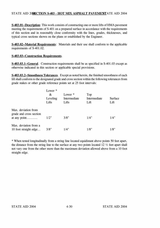
STATE AID 2004 STATE AID 2004
STATE AID 2004 STATE AID 20044-30
SECTION S-403 - HOT MIX ASPHALT PAVEMENT
S-403.01--Description: This work consists of constructing one or more lifts of HMA pavementmeeting the requirements of S-401 on a prepared surface in accordance with the requirementsof this section and in reasonably close conformity with the lines, grades, thicknesses, andtypical cross sections shown on the plans or established by the Engineer.
S-403.02--Material Requirements: Materials and their use shall conform to the applicablerequirements of S-401.02.
S-403.03--Construction Requirements.
S-403.03.1--General. Construction requirements shall be as specified in S-401.03 except asotherwise indicated in this section or applicable special provisions.
S-403.03.2--Smoothness Tolerances. Except as noted herein, the finished smoothness of eachlift shall conform to the designated grade and cross section within the following tolerances fromgrade stakes or other grade reference points set at 25 foot intervals:
Lower * & Lower * Top
Leveling Intermediate Intermediate SurfaceLifts Lifts Lift Lift
Max. deviation fromgrade and cross sectionat any point........... 1/2" 3/8" 1/4" 1/4"
Max. deviation from a10 foot straight edge... 3/8" 1/4" 1/8" 1/8"
* When tested longitudinally from a string line located equidistant above points 50 feet apart,the distance from the string line to the surface at any two points located 12 ½ feet apart shallnot vary one from the other more than the maximum deviation allowed above from a 10 footstraight edge.
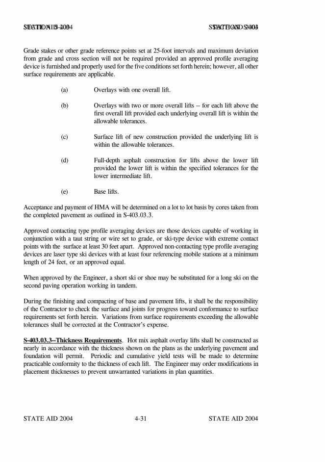
STATE AID 2004 STATE AID 2004
STATE AID 2004 STATE AID 20044-31
SECTION S-403 SECTION S-403
Grade stakes or other grade reference points set at 25-foot intervals and maximum deviationfrom grade and cross section will not be required provided an approved profile averagingdevice is furnished and properly used for the five conditions set forth herein; however, all othersurface requirements are applicable.
(a) Overlays with one overall lift.
(b) Overlays with two or more overall lifts -- for each lift above thefirst overall lift provided each underlying overall lift is within theallowable tolerances.
(c) Surface lift of new construction provided the underlying lift iswithin the allowable tolerances.
(d) Full-depth asphalt construction for lifts above the lower liftprovided the lower lift is within the specified tolerances for thelower intermediate lift.
(e) Base lifts.
Acceptance and payment of HMA will be determined on a lot to lot basis by cores taken fromthe completed pavement as outlined in S-403.03.3.
Approved contacting type profile averaging devices are those devices capable of working inconjunction with a taut string or wire set to grade, or ski-type device with extreme contactpoints with the surface at least 30 feet apart. Approved non-contacting type profile averagingdevices are laser type ski devices with at least four referencing mobile stations at a minimumlength of 24 feet, or an approved equal.
When approved by the Engineer, a short ski or shoe may be substituted for a long ski on thesecond paving operation working in tandem.
During the finishing and compacting of base and pavement lifts, it shall be the responsibilityof the Contractor to check the surface and joints for progress toward conformance to surfacerequirements set forth herein. Variations from surface requirements exceeding the allowabletolerances shall be corrected at the Contractor’s expense.
S-403.03.3--Thickness Requirements. Hot mix asphalt overlay lifts shall be constructed asnearly in accordance with the thickness shown on the plans as the underlying pavement andfoundation will permit. Periodic and cumulative yield tests will be made to determinepracticable conformity to the thickness of each lift. The Engineer may order modifications inplacement thicknesses to prevent unwarranted variations in plan quantities.
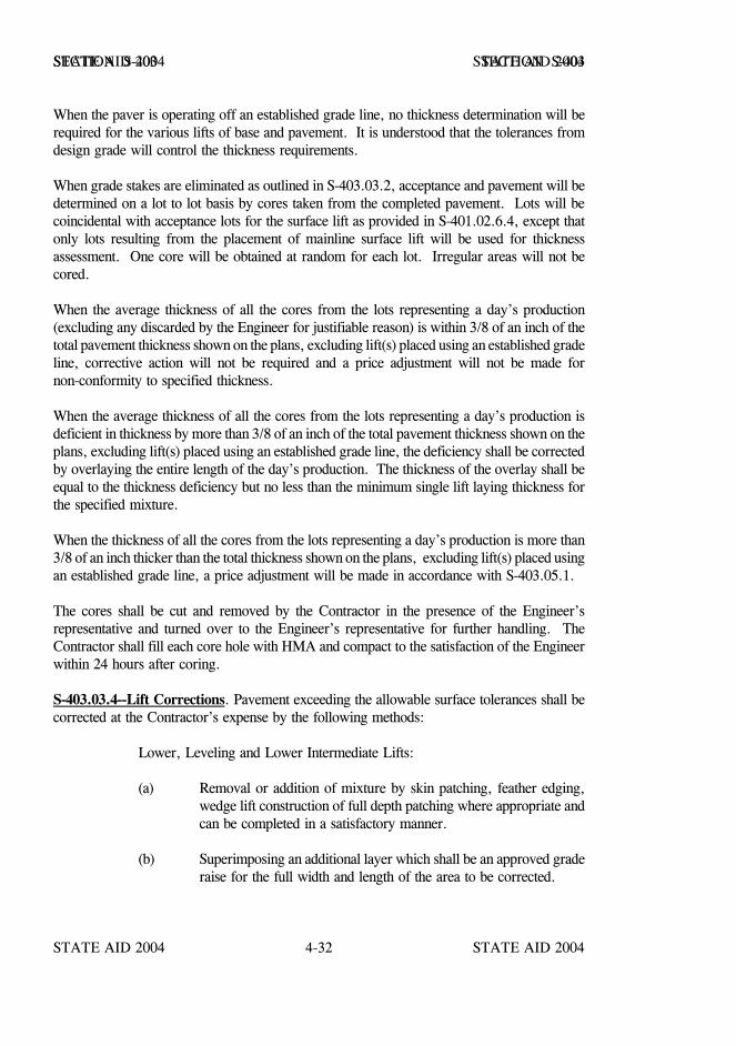
STATE AID 2004 STATE AID 2004
STATE AID 2004 STATE AID 20044-32
SECTION S-403 SECTION S-403
When the paver is operating off an established grade line, no thickness determination will berequired for the various lifts of base and pavement. It is understood that the tolerances fromdesign grade will control the thickness requirements.
When grade stakes are eliminated as outlined in S-403.03.2, acceptance and pavement will bedetermined on a lot to lot basis by cores taken from the completed pavement. Lots will becoincidental with acceptance lots for the surface lift as provided in S-401.02.6.4, except thatonly lots resulting from the placement of mainline surface lift will be used for thicknessassessment. One core will be obtained at random for each lot. Irregular areas will not becored.
When the average thickness of all the cores from the lots representing a day’s production(excluding any discarded by the Engineer for justifiable reason) is within 3/8 of an inch of thetotal pavement thickness shown on the plans, excluding lift(s) placed using an established gradeline, corrective action will not be required and a price adjustment will not be made fornon-conformity to specified thickness.
When the average thickness of all the cores from the lots representing a day’s production isdeficient in thickness by more than 3/8 of an inch of the total pavement thickness shown on theplans, excluding lift(s) placed using an established grade line, the deficiency shall be correctedby overlaying the entire length of the day’s production. The thickness of the overlay shall beequal to the thickness deficiency but no less than the minimum single lift laying thickness forthe specified mixture.
When the thickness of all the cores from the lots representing a day’s production is more than3/8 of an inch thicker than the total thickness shown on the plans, excluding lift(s) placed usingan established grade line, a price adjustment will be made in accordance with S-403.05.1.
The cores shall be cut and removed by the Contractor in the presence of the Engineer’srepresentative and turned over to the Engineer’s representative for further handling. TheContractor shall fill each core hole with HMA and compact to the satisfaction of the Engineerwithin 24 hours after coring.
S-403.03.4--Lift Corrections. Pavement exceeding the allowable surface tolerances shall becorrected at the Contractor’s expense by the following methods:
Lower, Leveling and Lower Intermediate Lifts:
(a) Removal or addition of mixture by skin patching, feather edging,wedge lift construction of full depth patching where appropriate andcan be completed in a satisfactory manner.
(b) Superimposing an additional layer which shall be an approved graderaise for the full width and length of the area to be corrected.
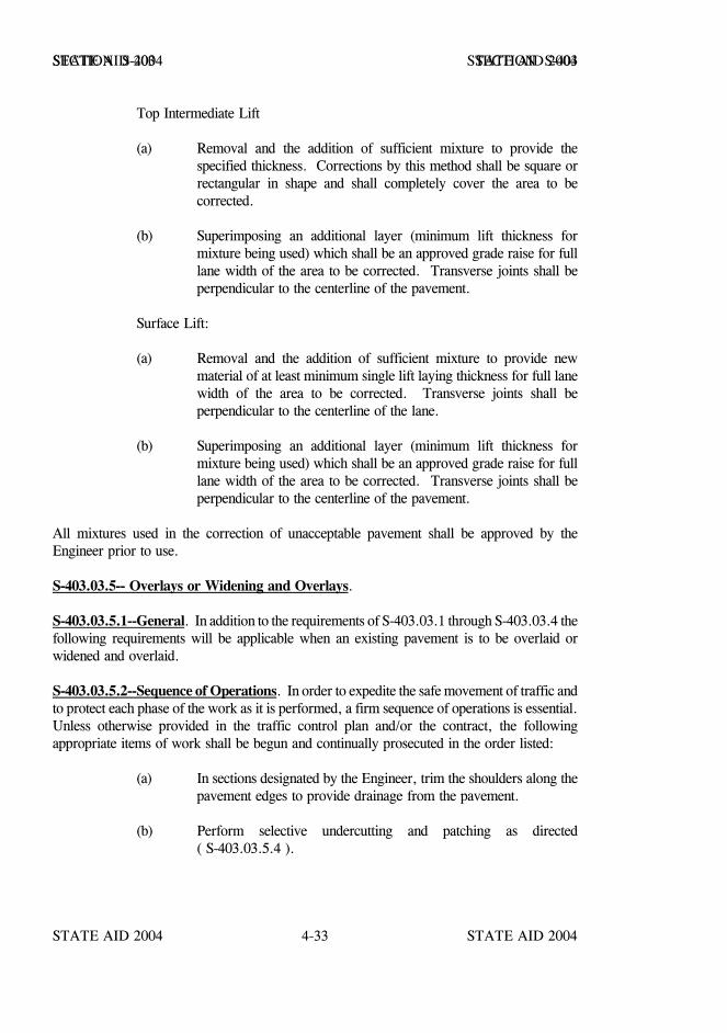
STATE AID 2004 STATE AID 2004
STATE AID 2004 STATE AID 20044-33
SECTION S-403 SECTION S-403
Top Intermediate Lift
(a) Removal and the addition of sufficient mixture to provide thespecified thickness. Corrections by this method shall be square orrectangular in shape and shall completely cover the area to becorrected.
(b) Superimposing an additional layer (minimum lift thickness formixture being used) which shall be an approved grade raise for fulllane width of the area to be corrected. Transverse joints shall beperpendicular to the centerline of the pavement.
Surface Lift:
(a) Removal and the addition of sufficient mixture to provide newmaterial of at least minimum single lift laying thickness for full lanewidth of the area to be corrected. Transverse joints shall beperpendicular to the centerline of the lane.
(b) Superimposing an additional layer (minimum lift thickness formixture being used) which shall be an approved grade raise for fulllane width of the area to be corrected. Transverse joints shall beperpendicular to the centerline of the pavement.
All mixtures used in the correction of unacceptable pavement shall be approved by theEngineer prior to use.
S-403.03.5-- Overlays or Widening and Overlays.
S-403.03.5.1--General. In addition to the requirements of S-403.03.1 through S-403.03.4 thefollowing requirements will be applicable when an existing pavement is to be overlaid orwidened and overlaid.
S-403.03.5.2--Sequence of Operations. In order to expedite the safe movement of traffic andto protect each phase of the work as it is performed, a firm sequence of operations is essential.Unless otherwise provided in the traffic control plan and/or the contract, the followingappropriate items of work shall be begun and continually prosecuted in the order listed:
(a) In sections designated by the Engineer, trim the shoulders along thepavement edges to provide drainage from the pavement.
(b) Perform selective undercutting and patching as directed( S-403.03.5.4 ).
STATE AID 2004 STATE AID 2004
STATE AID 2004 STATE AID 20044-34
SECTION S-403 SECTION S-403
(c) Clean and seal joints. (If required)
(d) Complete preparation on one side of roadway to be widened andplace widening materials.
(e) Reconstruct shoulders to elevation necessary to assure traffic safety.
(f) Open the widened section to traffic.
(g) Complete above work for other side of roadway.
(h) Perform preliminary leveling as directed.
(i) Apply interlayer (If required).
(j) Place the first overall leveling lift. (If required)
(k) After the first overall leveling lift, reconstruct shoulders as necessaryto eliminate vertical differentials which may be hazardous to traffic.
(l) Place first intermediate lift. (If required)
(m) Construct shoulders to the contiguous elevation as required.
(n) Place remaining intermediate lift (if required)
(o) Place surface lift.
(p) Complete construction of shoulders.
(q) Apply permanent traffic marking.
(r) Final cleanup.
The above operations shall be performed in such a manner that traffic will be maintained ona paved surface at all times. Two-lane highways should not be restricted to a single lane inexcess of a 3,000 foot section.
STATE AID 2004 STATE AID 2004
STATE AID 2004 STATE AID 20044-35
SECTION S-403 SECTION S-403
S-403.03.5.3--Widening of Base or Pavement. The foundation for widening shall be formedby trenching or excavating to the required depth and constructing a smooth, firm andcompacted foundation. It shall have sufficient density and stability to withstand the placementand compaction of subsequent lifts. Soft, yielding and other unsuitable material which theEngineer determines will not compact readily shall be removed and backfilled with granularmaterial or hot mix asphalt as directed.
Except as provided herein, excavation for widening, undercutting or other required excavationshall be spread along the edge of the shoulders, foreslopes or other adjacent areas as directedand will be an absorbed item. When the quantity is in excess of what may be usedsatisfactorily on adjacent areas, the Engineer may direct that the material be loaded, hauled andspread uniformly on other designated areas. In this case, compensation for handling surplusmaterial will be in accordance with the appropriate pay items as provided in the contract or asextra work.
If the plans require widening of the shoulders or embankment with contractor furnishedmaterial, all suitable material obtained from widening excavation may be used and will bemeasured and paid for as Contractor furnished materials. No measurement for payment ofhaul will be made.
Removal and disposal of old stakes, forms and other debris encountered in excavating shall bein accordance with S-201 and shall be considered as incidental to and included in the unit pricesbid for other items. No separate measurement will be made therefor. Pavement edges andsurfaces shall be cleaned prior to final shaping and compaction of adjacent trenching orundercut areas.
Granular material for widening shall be placed on a previously prepared, smooth, firm andunyielding foundation in accordance with the typical section. Density of the granular materialshall be that specified for subbase.
Hot mix asphalt for widening, including trench widening, shall meet the applicablerequirements of this section and S-401 and shall be placed in one or more layers as shown onthe plans or as directed. The surface of the mixture shall be finished as a continuation of theadjacent pavement slope.
Trench rollers or other compaction equipment shall be used to compact the foundation,granular material and bituminous mixtures for widening when standard width rolling equipmentcannot be used.
S-403.03.5.4--Patching. Existing pavement which has failed or unsatisfactorily stabilized shallbe removed as directed. Removal of pavement will be measured and paid for under theappropriate pay items as provided in the contract.
Backfill shall consist of hot mix asphalt or a combination of compacted layers of granularmaterial and hot mix asphalt. Unless otherwise specified, the Engineer will make thisdetermination based on depth and field conditions.
STATE AID 2004 STATE AID 2004
STATE AID 2004 STATE AID 20044-36
SECTION S-403 SECTION S-403
Hot mix asphalt used for backfilling will be measured and paid for at the contract unit price forthe mixture designated on the plans as the lowest lift. Granular material will be measured andpaid for under the appropriate pay item as provided in the contract or as extra work.
S-403.03.5.5--Preliminary Leveling. All irregularities of the existing base or pavement thatresult in a thickness greater than approximately two and one-half inches for the first overallleveling lift shall be corrected by skin patching, feather edging or a wedge lift and shall beapproved by the Engineer in advance of placing the first overall lift.
S-403.03.5.6--Placement of Lifts. The leveling lift shall be placed in a layer (or layers) notexceeding approximately two and one-half inches compacted thickness.
When single lane construction is required, placement of a lift on the adjacent lane may beperformed by an approved profile averaging device provided the lane previously placed iswithin the allowable tolerances for all surface requirements. When any of the tolerances areexceeded, the contractor shall reestablish the control string line for laying the adjacent laneshould he elect to perform this work prior to correcting the deficiencies of the lane previouslyplaced. In no case shall a “matching shoe” be used to control the grade of an adjacent lane.
In instances where there are only minor deviations from the allowable tolerances in the firstoverall lift, the Engineer may permit the Contractor to place the next higher lift by gradedstring line in lieu of making the corrections.
Single lane placement of leveling, intermediate and surface lifts shall be limited to the distancecovered in one and one-half days in advance of that placed in the adjacent lane.
S-403.03.5.7--Protection of Pavement. The base and pavement shall be protected andproperly maintained until it has been compacted and cooled sufficiently for use by traffic.
S-403.04--Method of Measurement. HMA pavement, complete in place and accepted, willbe measured by the ton. The weight of the composite mixture shall be determined inaccordance with the provisions of S-401.03.2.1.11.
Unless shown as a separate pay item, the furnishing and application of the tack coat will notbe measured for payment. When payment is provided, tack coat will be measured as set outin S-407.06.
The quantity of bituminous mixture required to correct the work, when made at the expenseof the Contractor, will not be measured for payment.
STATE AID 2004 STATE AID 2004
STATE AID 2004 STATE AID 20044-37
SECTION S-403 SECTION S-403
Any trenching required for widening will not be measured for payment; the cost thereof shallbe included in other items of work.
Undercut required by the Engineer will be measured for payment under the appropriateexcavation item as provided in the contract or as extra work. Pavement removal and anyrequired trenching will not be included in the measurement for undercut.
S-403.05--Basis of Payment. Subject to the adjustments set out in S-401.02.6.3, S-401.02.6.4& S-403.03.2, hot mix asphalt pavement, complete-in-place, accepted, and measured asprescribed above, will be paid for at the contract unit price per ton for each lift of pavementspecified in the bid schedule and shall be full compensation for completing the work.
S-403.05.1--Price Adjustment for Thickness Requirement. When grade stakes areeliminated as provided in S-403.03.3 and the average thickness of all cores from lotsrepresenting a day’s production is more than 3/8 inch thicker than the total specified thicknessof the pavement, excluding lift(s) placed using an established grade line, a lump sum reductionin payment for the surface lift of lots representing a day’s production will be made as follows:
(Individual Day’s (Monetary Value of the Day’s (D - 3/8) = X
L.S. Reduction) Surface Lift Production) ST
Where:
D = The day’s average deviation from total pavement thickness shown on the plansexcluding lift(s) placed using an established grade line.
ST = Specified thickness for lift.
The total L.S. reduction for the project is the summation of the individual day’s reductions inpayment.
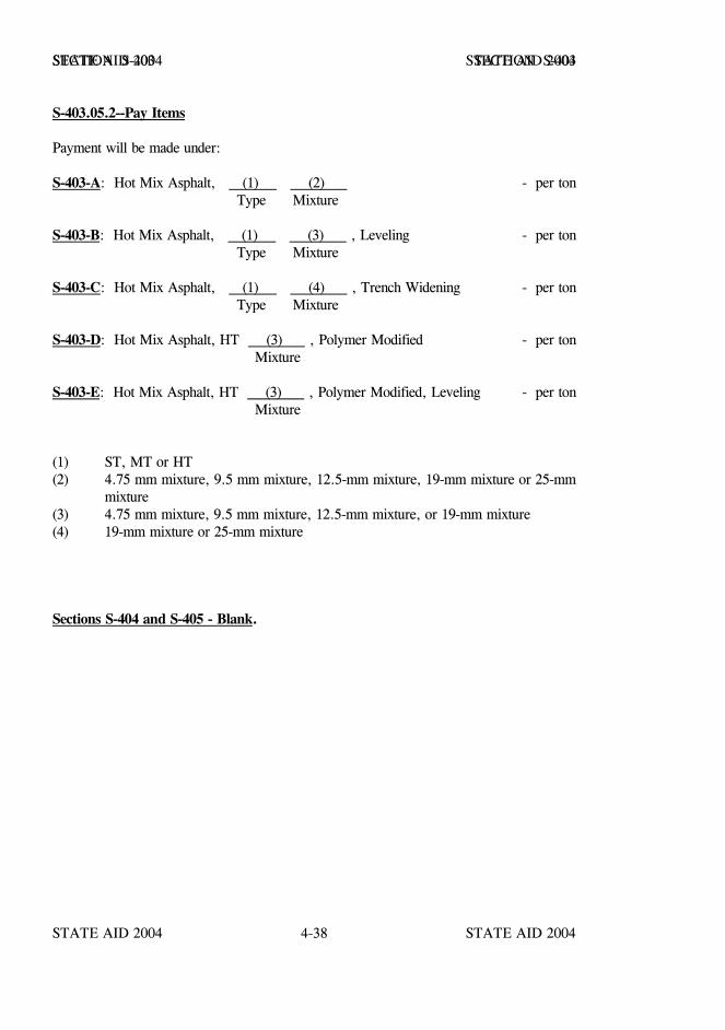
STATE AID 2004 STATE AID 2004
STATE AID 2004 STATE AID 20044-38
SECTION S-403 SECTION S-403
S-403.05.2--Pay Items
Payment will be made under:
S-403-A: Hot Mix Asphalt, (1) (2) - per ton Type Mixture
S-403-B: Hot Mix Asphalt, (1) (3) , Leveling - per ton Type Mixture
S-403-C: Hot Mix Asphalt, (1) (4) , Trench Widening - per ton Type Mixture
S-403-D: Hot Mix Asphalt, HT (3) , Polymer Modified - per ton Mixture
S-403-E: Hot Mix Asphalt, HT (3) , Polymer Modified, Leveling - per ton Mixture
(1) ST, MT or HT(2) 4.75 mm mixture, 9.5 mm mixture, 12.5-mm mixture, 19-mm mixture or 25-mm
mixture(3) 4.75 mm mixture, 9.5 mm mixture, 12.5-mm mixture, or 19-mm mixture(4) 19-mm mixture or 25-mm mixture
Sections S-404 and S-405 - Blank.
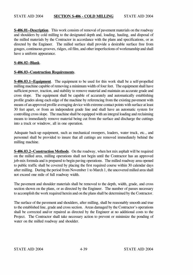
STATE AID 2004 STATE AID 2004
STATE AID 2004 STATE AID 20044-39
SECTION S-406 - COLD MILLING
S-406.01--Description. This work consists of removal of pavement materials on the roadwayand shoulders by cold milling to the designated depth and, loading, hauling, and disposal ofthe milled materials by the Contractor in accordance with the plans and specifications, or asdirected by the Engineer. The milled surface shall provide a desirable surface free fromgouges, continuous grooves, ridges, oil film, and other imperfections of workmanship and shallhave a uniform appearance.
S-406.02--Blank.
S-406.03--Construction Requirements.
S-406.03.1--Equipment. The equipment to be used for this work shall be a self-propelledmilling machine capable of removing a minimum width of four feet. The equipment shall havesufficient power, traction, and stability to remove material and maintain an accurate grade andcross slope. The equipment shall be capable of accurately and automatically establishingprofile grades along each edge of the machine by referencing from the existing pavement withmeans of an approved profile averaging device with extreme contact points with surface at least30 feet apart, or from an independent grade line and shall have an automatic system forcontrolling cross slope. The machine shall be equipped with an integral loading and reclaimingmeans to immediately remove material being cut from the surface and discharge the cuttingsinto a truck or windrow, all in one operation.
Adequate back-up equipment, such as mechanical sweepers, loaders, water truck, etc., andpersonnel shall be provided to insure that all cuttings are removed immediately behind themilling machine.
S-406.03.2--Construction Methods. On the roadway, when hot mix asphalt will be requiredon the milled area, milling operations shall not begin until the Contractor has an approvedjob-mix formula and is prepared to begin paving operations. The milled roadway area openedto public traffic shall be covered by placing the first required course within 30 calendar daysafter milling. During the period from November 1 to March 1, the uncovered milled area shallnot exceed one mile of full roadway width.
The pavement and shoulder materials shall be removed to the depth, width, grade, and crosssection shown on the plans, or as directed by the Engineer. The number of passes necessaryto accomplish the work required herein and on the plans shall be determined by the Contractor.
The surface of the pavement and shoulders, after milling, shall be reasonably smooth and trueto the established line, grade and cross section. Areas damaged by the Contractor's operationsshall be corrected and/or repaired as directed by the Engineer at no additional costs to theProject. The Contractor shall take necessary action to prevent or minimize the ponding ofwater on the milled roadway and shoulder.
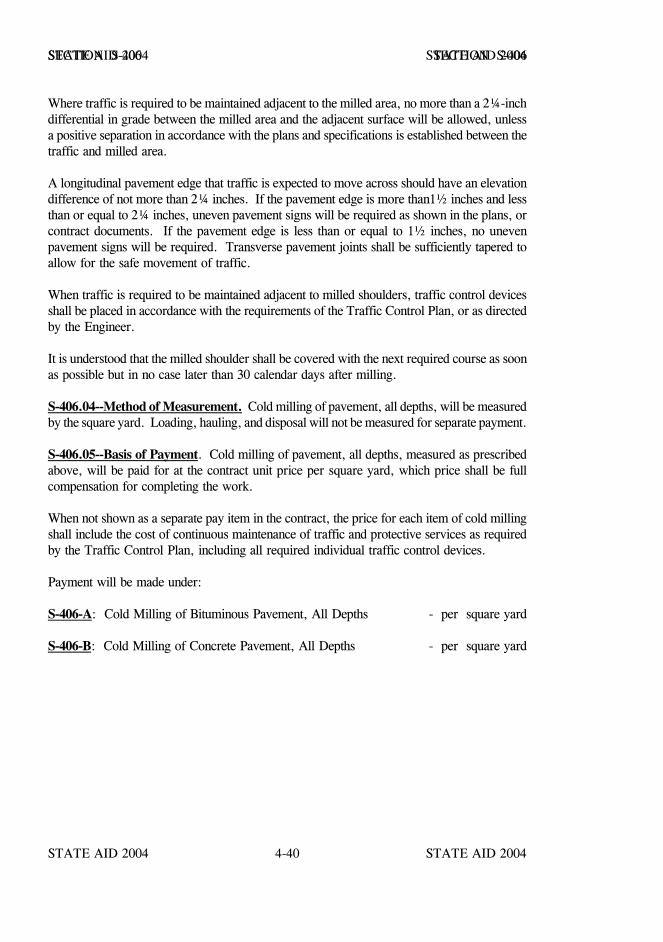
STATE AID 2004 STATE AID 2004
STATE AID 2004 STATE AID 20044-40
SECTION S-406 SECTION S-406
Where traffic is required to be maintained adjacent to the milled area, no more than a 2¼-inchdifferential in grade between the milled area and the adjacent surface will be allowed, unlessa positive separation in accordance with the plans and specifications is established between thetraffic and milled area.
A longitudinal pavement edge that traffic is expected to move across should have an elevationdifference of not more than 2¼ inches. If the pavement edge is more than1½ inches and lessthan or equal to 2¼ inches, uneven pavement signs will be required as shown in the plans, orcontract documents. If the pavement edge is less than or equal to 1½ inches, no unevenpavement signs will be required. Transverse pavement joints shall be sufficiently tapered toallow for the safe movement of traffic.
When traffic is required to be maintained adjacent to milled shoulders, traffic control devicesshall be placed in accordance with the requirements of the Traffic Control Plan, or as directedby the Engineer.
It is understood that the milled shoulder shall be covered with the next required course as soonas possible but in no case later than 30 calendar days after milling.
S-406.04--Method of Measurement. Cold milling of pavement, all depths, will be measuredby the square yard. Loading, hauling, and disposal will not be measured for separate payment.
S-406.05--Basis of Payment. Cold milling of pavement, all depths, measured as prescribedabove, will be paid for at the contract unit price per square yard, which price shall be fullcompensation for completing the work.
When not shown as a separate pay item in the contract, the price for each item of cold millingshall include the cost of continuous maintenance of traffic and protective services as requiredby the Traffic Control Plan, including all required individual traffic control devices.
Payment will be made under:
S-406-A: Cold Milling of Bituminous Pavement, All Depths - per square yard
S-406-B: Cold Milling of Concrete Pavement, All Depths - per square yard
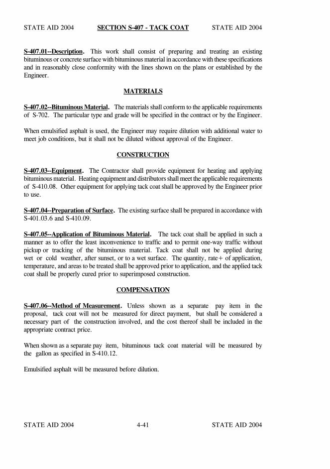
STATE AID 2004 STATE AID 2004
STATE AID 2004 STATE AID 20044-41
SECTION S-407 - TACK COAT
S-407.01--Description. This work shall consist of preparing and treating an existingbituminous or concrete surface with bituminous material in accordance with these specificationsand in reasonably close conformity with the lines shown on the plans or established by theEngineer.
MATERIALS
S-407.02--Bituminous Material. The materials shall conform to the applicable requirementsof S-702. The particular type and grade will be specified in the contract or by the Engineer.
When emulsified asphalt is used, the Engineer may require dilution with additional water tomeet job conditions, but it shall not be diluted without approval of the Engineer.
CONSTRUCTION
S-407.03--Equipment. The Contractor shall provide equipment for heating and applyingbituminous material. Heating equipment and distributors shall meet the applicable requirementsof S-410.08. Other equipment for applying tack coat shall be approved by the Engineer priorto use.
S-407.04--Preparation of Surface. The existing surface shall be prepared in accordance withS-401.03.6 and S-410.09.
S-407.05--Application of Bituminous Material. The tack coat shall be applied in such amanner as to offer the least inconvenience to traffic and to permit one-way traffic withoutpickup or tracking of the bituminous material. Tack coat shall not be applied duringwet or cold weather, after sunset, or to a wet surface. The quantity, rate+ of application,temperature, and areas to be treated shall be approved prior to application, and the applied tackcoat shall be properly cured prior to superimposed construction.
COMPENSATION
S-407.06--Method of Measurement. Unless shown as a separate pay item in theproposal, tack coat will not be measured for direct payment, but shall be considered anecessary part of the construction involved, and the cost thereof shall be included in theappropriate contract price.
When shown as a separate pay item, bituminous tack coat material will be measured bythe gallon as specified in S-410.12.
Emulsified asphalt will be measured before dilution.
STATE AID 2004 STATE AID 2004
STATE AID 2004 STATE AID 20044-42
SECTION S-407 SECTION S-407
S-407.07--Basis of Payment. When shown as a separate pay item in the contract, tackcoat will be paid for at the contract unit price per gallon, which price shall be fullcompensation for completing the work specified.
Payment will be made under:
S-407-A: Asphalt for Tack Coat, ( ) - per gallon (Grade)
STATE AID 2004 STATE AID 2004
STATE AID 2004 STATE AID 20044-43
SECTION S-408 - PRIME COAT
S-408.01--Description. This work shall consist of preparing and treating an existing surfacewith bituminous material and blotter material, if required, in accordance with thesespecifications and in reasonably close conformity with the lines shown on the plans orestablished by the Engineer.
MATERIALS
S-408.02--Bituminous Materials. The bituminous material shall conform to the applicablerequirements of S-702. The type and grade of bituminous material will be specified in thecontract. The grade may be changed one step by the Engineer at no change in unit price.
S-408.03--Blotter Material. Blotter material shall be sand-clay or other friable or near friablematerials approved by the Engineer.
CONSTRUCTION REQUIREMENTS
S-408.04--Seasonal and Weather Limitations. Bituminous material shall be applied onlywhen permitted under the seasonal and weather limitations specified in S-410.07.
S-408.05--Equipment. The Contractor shall provide equipment for heating and applyingbituminous material. Heating equipment and distributors shall meet the requirementsof S-410.08.
S-408.06--Preparation of Surface. The surface to be primed shall be free from all ruts,corrugations, segregated material or other irregularities, and shall be conditioned as specifiedin S-410.09.
S-408.07--Application of Bituminous Material. The bituminous material shall be applied inaccordance with applicable requirements of S-410.10.
S-408.08--Application of Blotter Material. The Contractor shall furnish and spread, withoutextra compensation, the minimum necessary quantity of approved blotter material over theprime coat.
S-408.09--Maintenance. The Contractor shall maintain the prime coat in a satisfactorycondition until covered by subsequent construction. Maintenance shall include immediaterepairs of all damage that may occur. All maintenance shall be performed at the expense ofthe Contractor, and shall be repeated as often as necessary to properly maintain the work.
STATE AID 2004 STATE AID 2004
STATE AID 2004 STATE AID 20044-44
SECTION S-408 SECTION S-408
COMPENSATION
S-408.10--Method of Measurement. Bituminous material will be measured by the gallon asspecified in S-410.12. Blotter material will not be paid for separately but shall be included inthe price bid per gallon for prime coat.
S-408.11--Basis of Payment. Prime coat will be paid for at the contract unit price per gallonas specified in S-410.13.
Payment will be made under:
S-408-A: Asphalt for Prime Coat ( ) - per gallon Grade
STATE AID 2004 STATE AID 2004
STATE AID 2004 STATE AID 20044-45
SECTION S-409 - GEOTEXTILE FABRIC FOR UNDERSEAL
S-409.01--Description. This work consists of furnishing and placing fabric underseal inaccordance with the details shown on the plans and the requirements of these specifications.An underseal shall consist of an application of asphalt cement covered with a layer of fabric.
S-409.02--Materials.
S-409.02.1--Geotextile Fabric. The fabric shall meet the specific requirements for geotextilefabric underseal contained in S-714.13.4.
S-409.02.2--Bituminous Material. Unless otherwise designated, the asphalt sealant shall beasphalt cement Grade PG 64-22 meeting the applicable requirements of S-702.
S-409.03--Construction Requirements.
S-409.03.1--Equipment. The Contractor shall provide equipment for heating and applyingbituminous material and for laying the pavement fabric.Heating equipment and distributorsshall meet the requirements of S-410.
The mechanical fabric laydown equipment shall be capable of handling full rolls of fabric andshall be capable of laying the fabric smoothly without excessive wrinkles and/or folds. Whenmanual laydown is required, a length of standard one inch pipe and suitable roll tension devicesshall be used for proper roll handling.The fabric manufacturer or distributor shall furnish atechnician to supervise installation of the fabric and training of Contractor's personnel.
S-409.03.2--Surface Preparation. The surface to be treated, and at least one additional footon each side, shall be cleaned by sweeping, blowing, or other methods until all dust, dirt, mud,vegetation, and foreign materials are removed entirely from the pavement before the asphaltsealant is applied. Care shall be exercised to prevent material so removed from becomingmixed with subsequent courses.
S-409.03.3--Application of the Asphalt Sealant. The application of the asphalt sealant shallconform to the applicable requirements of S-410. The sealant shall be uniformly sprayed overthe area to be covered by fabric at a rate recommended by the fabric manufacturer ordistributor's technician and/or ordered by the Engineer. The rate of application is usuallybetween 0.20 and 0.40 gallon per square yard. Varying surface conditions such as the degreeof porosity of the existing pavement will cause varying application rates. The quantity appliedshall be sufficient to bond and saturate the fabric, and to bond the subsequent overlay courseto the fabric. Within intersections or other zones wherevehicle braking is frequent, theapplication rate should be reduced. The sealant shall be applied to an area two to six incheswider than the width of fabric being placed, but restricted to the area of immediate fabriclaydown.
STATE AID 2004 STATE AID 2004
STATE AID 2004 STATE AID 20044-46
SECTION S-409 SECTION S-409
Application shall be by distributor spray bar with hand hose spraying allowed only where thedistributor spray bar cannot be used. Asphalt leakage from the distributor and any spillageshall be cleaned from the road surface to avoid flushing and possible fabric movement at theseasphalt rich areas. The asphalt cement used as a sealant shall have distributor tank temperaturebetween 300°F and 350°F, except when applying a tack coat to the fabric, the temperatureshall not exceed 320°F to avoid damaging the fabric.
S-409.03.4--Fabric Placement. The fabric shall be placed on the asphaltic sealant as soon aspractical and before the adhesion properties of the sealant is lost. The fabric shall be placedas smoothly as possible to avoid wrinkles.
Wrinkles severe enough to cause "folds" shall be slit and laid flat. Small wrinkles which flattenunder compaction are not detrimental to performance. The fabric shall be broomed orsqueegeed to remove air bubbles and make complete contact with the road surface asrecommended by the fabric manufacturer or distributor. The fabric shall be laid straight,however moderate curves can be negotiated by stretching the fabric on the outside of the curve.
Longitudinal and transverse joints shall be made by overlapping the fabric at least six inches.Additional sealant shall be applied to the joints as required and may be applied by hand hosespraying or with mop and bucket if extreme care is taken to not over apply. Transverse jointsshould be "shingled" in the direction of construction traffic and paving to prevent pick-up. Incircumstances where this method is impractical, asphalt pavement or sand spread over the jointwill aid in prevention of pick-up.
When recommended by the manufacturer or distributor's technician and/or ordered by theEngineer, the fabric shall be rolled with a pneumatic roller to improve bonding and reduceslippage.
S-409.03.5--Treatment of Fabric Prior to Overlay. Normally it is not necessary to tack coatthe fabric unless there are circumstances such as delay in placement of subsequent course, dustaccumulation or insufficient initial application of sealant which would make tack coatingdesirable. If a tack coat is required by the Engineer, emulsified asphalt shall be applied at arate of 0.02 to 0.05 gallon of residual asphalt per square yard.
Placement of the subsequent course shall closely follow fabric laydown. In the event that thesealant bleeds through the fabric, it may be necessary to blot the sealant with sand to preventconstruction equipment from picking up the fabric. Turning of the paver and other vehiclesmust be gradual to avoid strippage or damage to the fabric.
STATE AID 2004 STATE AID 2004
STATE AID 2004 STATE AID 20044-47
SECTION S-409 SECTION S-409
If traffic must be maintained on the fabric prior to placement of the subsequent course, it isadvisable to spread a small quantity of sand over the fabric and roll with a pneumatic roller toprevent tires from picking up the fabric.
If rain should cause a blistered appearance and bond loss, it shall be corrected by rolling witha pneumatic roller.
S-409.03.6--Asphalt Pavement Overlay. The overlay shall conform to S-401 and S-403except that the mixture shall be delivered to the paver at a temperature of 275°F to 300°F.Temperature of the mix shall in no case exceed 325°F.
S-409.04--Method of Measurement. Geotextile fabric for underseal, placed in accordancewith these specifications and as directed by the Engineer, will be measured by the square yardof surface area. Any overwidth of material installed and additional material required for lapswill not be measured.
Asphalt cement for fabric underseal, applied in accordance with these specifications and asdirected by the Engineer, will be measured by the gallon in accordance with S- 410.
Any blotting with sand, rolling to restore bond and application of a tack coat will not bemeasured for payment and is considered incidental to completion of the work.
S-409.05--Basis of Payment. Geotextile fabric for underseal will be paid for at the contractunit price per square yard. Asphalt cement for fabric underseal of the kind and gradespecified, measured as provided above, will be paid for at the contract unit price per gallon.These prices shall be full compensation for satisfactorily completing the work.
Payment will be made under:
S-409-A: Geotextile Fabric for Underseal, Type * - per square yard
S-409-B: Asphalt Cement for Fabric Underseal - per gallon
* When not designated, see S-714.13.
STATE AID 2004 STATE AID 2004
STATE AID 2004 STATE AID 20044-48
SECTION S-410 - BITUMINOUS SURFACE TREATMENT
S-410.01--Description. This work shall consist of the construction of a single or multiple layerbituminous surface treatment in accordance with these specifications and in reasonably closeconformity with the lines shown on the plans or established by the Engineer.
MATERIALS
S-410.02--Bituminous Material. The type and grade of bituminous materials will be specifiedin the contract and conform to the applicable requirements of S-702.
If any aggregate course is composed of gravel, an anti-strip agent shall be added to asphaltcement.
The type anti-strip agent used shall be on the latest LIST OF APPROVED SOURCES OFMATERIALS as furnished by MDOT and will be incorporated into the liquid asphalt cementat the refinery at the rate of application specified.
The anti-strip agent will not be paid for directly but compensation will be considered includedin the prices bid for asphalt cement or aggregates.
S-410.03--Cover Material. Cover material shall meet the applicable requirements ofS-703.14, and the type will be specified in the contract.
Only one type of aggregate or combination of aggregates shall be used on a particular projectexcept with written permission of the State Aid Engineer.
Sites for stockpiles of cover material shall be grubbed and cleaned prior to storing theaggregates, and the ground shall be firm, smooth, and well drained.
S-410.03.1--Blotter Material. Blotter Material shall be sand-clay or other friable or nearfriable materials approved by the Engineer.
CONSTRUCTION REQUIREMENTS
S-410.04--Prime Coat. The prime coat, when specified, shall meet the requirements ofS-408.
During the period between the application of the prime coat and the bituminous surfacetreatment, the primed surface shall be kept in continuous repair. All holes, raveled areas, andareas deficient in prime shall be patched and repaired with approved materials.
S-410.05--Blotter Material. Blotter Material shall only be required if deemed necessary bythe Engineer.
STATE AID 2004 STATE AID 2004
STATE AID 2004 STATE AID 20044-49
SECTION S-410 SECTION S-410
S-410.06--Control of Traffic. During the construction of each layer of bituminous surfacetreatment, the Contractor shall regulate the speed of his vehicles and other traffic in order thatunnecessary damage to the course will be avoided.
S-410.07--Seasonal and Weather Limitations. Emulsified asphalt and cut-back asphalt shallbe applied only when the air temperature is above 60oF. Asphalt cement shall be applied onlywhen both the air and surface temperature is above 75oF.
Bituminous materials for the prime coat shall not be placed during the period between October1 and March 1, nor when the weather is rainy or foggy.
Bituminous materials for Bituminous Surface Treatment shall not be placed during the periodbetween October 15 and March 1, nor when the weather is rainy or foggy.
Bituminous materials for Re-seal shall not be placed during the period between October 1 andMarch 1, nor when the weather conditions are unfavorable for this type of construction.
On projects where completion of seal coats after October 15 or before March 1 is determinedto be in the public interest, the State Aid Engineer may permit variations from the above underthe condition that all the following requirements are met:
1. The air temperature is 60oF or higher.
2. Asphalt cement used is cut back with naphtha of the type that will yield from five toten (5-10) percent off at 680oF when tested by method AASHTO T-78.
3. The naphtha is added at the refinery.
4. Aggregate is satisfactorily air dried in covered storage, or mechanically dried.
5. The sun is shining.
6. Aggregate is applied immediately behind the distributor.
7. No shot is made after mid-afternoon, and rolling is increased as directed for shotsmade after noon.
8. The Contractor retains full responsibility for the acceptable quality of the work withinthe intent of the contract, these conditions notwithstanding.
9. The work is performed under these modifications at no additional cost to the County.
STATE AID 2004 STATE AID 2004
STATE AID 2004 STATE AID 20044-50
SECTION S-410 SECTION S-410
Blanket authorization will not be given for use of the above modification, but will be given onlywhen completion of the surface treatment would make the facility available for use by publictraffic, or for subsequent construction.
Prior to October 15 and after March 1, when the requirements of these specifications are beingmet, but conditions are less than good for the adhesion of cover aggregate to the bituminousmaterial, the Engineer may permit or require, at no additional cost to the County, the asphaltcement to be cut back with naphtha as previously indicated. Less than good placementconditions shall be understood to include, but not limited to: lower than desirabletemperature; higher than desirable humidity; surface dampness; or coolness of the foundationor aggregate. Such undesirable conditions will occur, and therefore, these measures must betaken considerably earlier in the more northern portions of the State.
S-410.08--Equipment. The following or equivalent shall be furnished:
S-410.08.1--Bituminous Heating Equipment. This equipment shall heat and maintain thebituminous material within specification requirements without damaging the material. Theheating equipment shall be supplied with at least one accurate asphalt thermometer.
S-410.08.2--Distributor. The distributor shall be mounted on pneumatic tires of sufficientwidth to prevent breaking the surface bond when the tank is fully loaded. It shall beself-propelled and sufficiently powered to maintain the desired speeds during operation. Itshall be equipped to evenly heat and maintain the material at the required temperature; haveadequate pressure devices and suitable manifolds to provide constant and even distribution forthe entire length of the spray bars; and have positive cutoff to prevent dripping from thenozzles. It shall be so constructed that uniform applications may be made at the specifiedrate on variable widths up to twenty-six (26) feet. Charts and devices shall be provided by theContractor for determining the quantity being applied.
S-410.08.3--Rotary Brooms. Rotary brooms shall be constructed to permit the revolutionsof the broom to be adjusted to its progression and to permit adjustment of the broom inrelation to the surface. The broom bristles shall be stiff enough to sweep clean withoutinjury to the surface.
S-410.08.4--Power Rollers. Steel-wheel rollers shall be self-propelled, rated at 5 to 8 tons,and shall have a weight of at least two hundred (200) pounds per inch of roller width.The rollers may be the three wheel type, but the tandem type is preferred.
STATE AID 2004 STATE AID 2004
STATE AID 2004 STATE AID 20044-51
SECTION S-410 SECTION S-410
Pneumatic rollers shall be self-propelled with wheels mounted on two axles in such a mannerthat the rear tires will not follow in the tracks of the forward group. The rollers shall becapable of applying a minimum of fifty (50) pounds per square inch contact pressure undereach tire, and shall be of a weight that will not damage the base or surface treatment.
S-410.08.5--Trucks. Trucks of sufficient number and size to adequately supply the materialshall be furnished.
S-410.08.6--Aggregate Spreaders. Aggregate spreaders shall be self-propelled andconstructed so that they can be accurately gauged and set to uniformly distribute the requiredquantity of aggregate at regulated speed.
S-410.08.7--Other Equipment. Drag brooms and blowers shall be furnished and used asconditions dictate.
S-410.09--Preparation of Surface. The entire surface to be treated and at least one footon each side shall be cleaned by sweeping, blowing, or other methods until all dust, mud,clay lumps, and foreign material is removed. A primed base shall be properly cured andapproved prior to application of bituminous material.
Testing requirements for Hot Mix Asphalt used for patching, base repair or leveling prior toreseal shall apply except as follows:
A. The requirement for field densities is hereby waived for Hot Mix Asphalt used forpatching, base repair and leveling on reseal projects. The Contractor shall berequired; however, to maintain a compactive effort as directed by the Engineer.
B. Mix designs or transfer of mix designs shall not be required for Hot Mix Asphalt(HMA) furnished by approved sources (plants currently supplying HMA for MDOTand/or State Aid projects).
C. The Contractor shall submit certification to the Engineer that the source of HMAhas been inspected and currently approved to supply HMA to MDOT and/or StateAid projects. In addition, form TMD 042 or equal, shall be furnished to theEngineer from each source and type mix incorporated into the project.
D. Certificate A or B shall continue to be required for asphalt cement or emulsion andthe material tested at the required frequencies noted in State Aid’s latest edition ofits Standard Operating Procedures (SOP’s).
STATE AID 2004 STATE AID 2004
STATE AID 2004 STATE AID 20044-52
SECTION S-410 SECTION S-410
S-410.10--Application of Bituminous Material. Bituminous material shall not be applied untilthe prepared surface has been approved by the Engineer. Where practicable, shots shallbe at least five hundred (500) feet in length, and longer shots are desirable. No shot shall bein excess of a length which can be covered with aggregate before the bitumen hardens.
The bituminous material shall be uniformly heated and maintained within the specifiedtemperature range during application. All material damaged by heating shall be rejected, andif a section has been treated with damaged material it shall be removed and replaced by theContractor without additional compensation.
The bituminous material shall be applied with a pressure distributor at the specified rate, andat the temperature specified by the Engineer within the range set out in S-702.12. It shall beuniformly applied at a width no wider than can be covered by one pass of the aggregatespreader or full width may be applied if the Contractor elects to use two aggregate spreaders.The application rate may be varied by the Engineer within the ranges set out in Table 410-A.
The application shall be stopped before the distributor is completely empty, and the length ofshots shall be computed so that the application is stopped before it begins to run light. At allstartings, including joints with preceding applications, intersections, and junctions with allpavements, etc., the distributor nozzles shall be operating at full force when the applicationbegins. Building paper or other suitable material shall be used to receive the initial applicationfrom the nozzles before the asphalt reaches the road surface at the joint. The material usedat the joint shall be removed immediately after use without spilling asphalt on the road surface.
Spray bar nozzles shall be kept clean at all times, and should one become blocked duringapplication of the bituminous material, the distributor shall be stopped immediately and thenozzle cleaned before proceeding. Bare or light areas shall be immediately made uniform byuse of a hand hose or pouring pot.
Due to possible spillage, the transfer of material from the delivery truck to the distributor shallbe outside the limits of the roadway. Bituminous material shall not be discharged on theright-of-way when cleaning out the distributor. Any spillage shall be removed from theroadway and right-of-way.
During application of bituminous material, the Contractor shall provide adequate protection toprevent marring or discoloration of pavements, structures, curbs, trees, etc., adjacent to thearea being treated.
Longitudinal joints shall be reasonably true to line and parallel to the centerline. Theoverlap in the application of the bituminous material shall be the minimum to assure completecoverage.
STATE AID 2004 STATE AID 2004
STATE AID 2004 STATE AID 20044-53
SECTION S-410 SECTION S-410
At construction joints, the treatment of the edges shall be blended so that there are no gaps; theelevations are the same; and the joints are free from ridges and depressions.
S-410.11--Application of Cover Coat Material. The application of cover material shallimmediately follow the application of bituminous material. Adhesion of the cover aggregateto the bitumen is the Contractor's responsibility. The time interval between applications ofbituminous material and cover aggregate shall not exceed 20 minutes when the air temperatureis below 85°F or 30 minutes when the temperature is 85°F or above.
Aggregate shall be spread directly from approved spreaders. Trucks or spreaders shall notdrive on the uncovered bituminous material.
The application rate of cover aggregate will be specified by the Engineer within the ranges setout in Table 410-A. The dry aggregate shall be spread uniformly to cover the bituminousmaterial with the quantity of mineral aggregate specified by the Engineer. All deficient areasshall be covered with additional material. All excess cover material shall be removed from thesurface and stockpiled or used as directed.
If needed, approved drag brooms and hand brooms shall be used to distribute the aggregateuniformly before and while rolling operations are in progress.
The entire application of aggregate shall be rolled as soon as possible after application. Rollingshall be continued and repeated as often as necessary to key the cover material thoroughly intothe bituminous material over the entire surface.
Pneumatic-tire rollers and steel-wheel rollers shall be used in the sequence that will provide therolling pattern that results in the best adhesion of the aggregate to the bituminous material andthe best surface qualities.
Subsequent to the initial application of the aggregate the Contractor shall distribute, as manytimes as is deemed necessary, loose aggregate over the surface to absorb free bituminousmaterial and to cover areas deficient in aggregate. Immediately following eachdistribution, the Contractor shall roll the entire surface treatment or seal with a pneumatic-tireroller until the maximum quantity of aggregate is embedded in the bitumen. Rolling in eachcase shall be at least one complete coverage and as many additional coverages as necessaryto properly embed the aggregate. All rolling shall be performed while the temperature isfavorable for sealing the aggregate into the bitumen.
In all cases there shall be at least five complete coverages of the entire surface of the treatmentwith a pneumatic-tire roller.
STATE AID 2004 STATE AID 2004
STATE AID 2004 STATE AID 20044-54
SECTION S-410 SECTION S-410
For variable application treatments or seals when the Engineer has determined that themaximum quantity of aggregate has been embedded on the first and/or second layer, theContractor shall sweep or otherwise remove all excess material but not displace any embeddedaggregate.
Maintenance of the surface shall include the distribution of cover aggregate over the surfaceto absorb any free bituminous material and to cover any deficient areas. Maintenance shall beconducted so as not to displace imbedded material. Excess Seal Aggregate shall be swept fromthe entire surface by rotary brooms prior to acceptance of work.
S-410.11.1--Stress Relief Layers. The application rates of bituminous material and coveraggregate for single surface treatment placed on an existing pavement as an interlayer belowhot mix asphalt shall be as shown on the plans or directed. As soon as the single surfacetreatment has been applied and satisfactorily rolled, a thin (minimum cover) layer of hot mixasphalt leveling course (unless otherwise shown on the plans) shall be placed immediately inorder to retain all aggregate of the surface treatment. Compaction of the hot mix asphalt layershall consist of a minimum of three complete coverages with the pneumatic-tire roller. Thesteel-wheel roller will not be required and no formal density tests will be made. The quantityof hot mix asphalt mixture acceptably used in the layer will be included in measurement forleveling course. Seasonal and temperature limitations will not apply to this type of surfacetreatment.
S-410.11.2--Maintenance. The Contractor will be required to properly maintain that portionof the highway surface covered by his contract until relieved of such responsibility by theEngineer and in no case shall such period of maintenance be less than fourteen (14) days afterthe application of the seal course.
COMPENSATION
S-410.12--Method of Measurement. Accepted bituminous material will be measured by thegallon in accordance with S-109. Unless otherwise specified, distributor tank measurement willbe used. The volume of material over five percent above the quantity ordered for each shotwill be deducted from measured quantities, except that fifteen (15) percent will be allowed forirregular areas where hand spraying is necessary.
Cover material and blotter material will be measured in cubic yards, (LVM) at the point ofdelivery on the road. Measurement will be for the actual volume spread. The volume ofmaterial over five percent above the quantity ordered for each "spreading" will be deductedfrom measured quantities, except that 15 percent will be allowed for irregular areas wherehand spreading is necessary.
STATE AID 2004 STATE AID 2004
STATE AID 2004 STATE AID 20044-55
SECTION S-410 SECTION S-410
The volume of all cover material and the volume of all bituminous material lost, wasted,damaged, or rejected, or applied outside of designated areas, or in excess of the Engineer'sdirections and tolerances allowed, or contrary to the specifications, will be deducted frommeasured quantities.
S-410.13--Basis of Payment. Bituminous material will be paid for at the contract unit priceper gallon. Cover material and blotter material will be paid for at the contract unit price percubic yard (LVM).
Work performed and measured as specified above will be paid for under the applicable payitems set out below for the specific type of work specified in the proposal and shall be fullcompensation for completing the work
Payment will be made under:
S-410-A: Asphalt Cement, Grade - per gallon
S-410-B: Cutback Asphalt, Grade - per gallon
S-410-C: Emulsified Asphalt, Grade - per gallon
S-410-C-1: Polymerized-Emulsified Asphalt, Grade CRS-2P - per gallon
S-410-D: Coarse Aggregate Cover Material, Size , Type - per cubic yard
S-410-E: Seal Aggregate Cover Material, Size , Type - per cubic yard
S-410-F: Blotter Material - per cubic yard
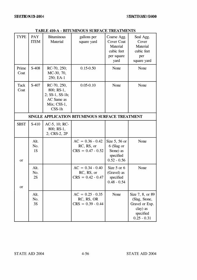
STATE AID 2004 STATE AID 2004
STATE AID 2004 STATE AID 20044-56
SECTION S-410 SECTION S-410
TABLE 410-A - BITUMINOUS SURFACE TREATMENTS
TYPE PAY ITEM
BituminousMaterial
gallons persquare yard
Coarse Agg.Cover Coat
Materialcubic feetper square
yard
Seal Agg.Cover
Materialcubic feet
per square yard
PrimeCoat
S-408 RC-70, 250;MC-30, 70,250; EA-1
0.15-0.50 None None
TackCoat
S-407 RC-70, 250,800; RS-1,
2; SS-1, SS-1h;AC Same asMix; CSS-1,
CSS-1h
0.05-0.10 None None
SINGLE APPLICATION BITUMINOUS SURFACE TREATMENT
SBST S-410 AC-5, 10; RC-800; RS-1,
2; CRS-2, 2P
or
Alt.No.1S
AC = 0.36 - 0.42RC, RS, or
CRS = 0.47 - 0.52
Size 5, 56 or6 (Slag orStone) asspecified
0.52 - 0.56
None
or
Alt.No.2S
AC = 0.34 - 0.40RC, RS, or
CRS = 0.42 - 0.47
Size 5 or 6(Gravel) as
specified0.48 - 0.54
None
Alt.No.3S
AC = 0.25 - 0.35RC, RS, OR
CRS = 0.39 - 0.44
None Size 7, 8, or 89(Slag, Stone,
Gravel or Exp.clay) as specified
0.25 - 0.31
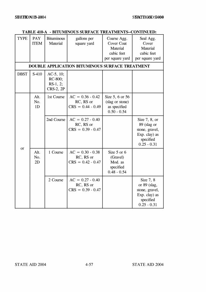
STATE AID 2004 STATE AID 2004
STATE AID 2004 STATE AID 20044-57
SECTION S-410 SECTION S-410
TABLE 410-A - BITUMINOUS SURFACE TREATMENTS--CONTINUED:
TYPE PAY ITEM
BituminousMaterial
gallons persquare yard
Coarse Agg.Cover Coat
Materialcubic feet
per square yard
Seal Agg.Cover
Materialcubic feet
per square yard
DOUBLE APPLICATION BITUMINOUS SURFACE TREATMENT
DBST S-410 AC-5, 10;RC-800;RS-1, 2;
CRS-2, 2P
or
Alt.No.1D
1st Course AC = 0.36 - 0.42RC, RS or
CRS = 0.44 - 0.49
Size 5, 6 or 56(slag or stone)as specified0.50 - 0.54
2nd Course AC = 0.27 - 0.40RC, RS or
CRS = 0.39 - 0.47
Size 7, 8, or89 (slag or
stone, gravel,Exp. clay) as
specified0.25 - 0.31
Alt.No.2D
1 Course AC = 0.30 - 0.38RC, RS or
CRS = 0.42 - 0.47
Size 5 or 6(Gravel)Mod. asspecified
0.48 - 0.54
2 Course AC = 0.27 - 0.40RC, RS or
CRS = 0.39 - 0.47
Size 7, 8or 89 (slag,
stone, gravel,Exp. clay) as
specified0.25 - 0.31
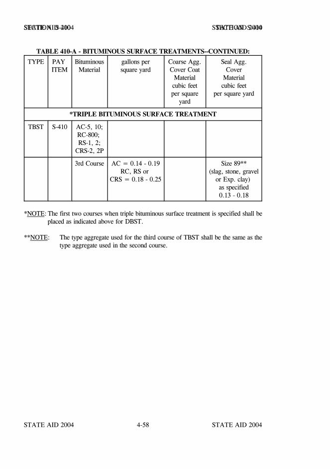
STATE AID 2004 STATE AID 2004
STATE AID 2004 STATE AID 20044-58
SECTION S-410 SECTION S-410
TABLE 410-A - BITUMINOUS SURFACE TREATMENTS--CONTINUED:
TYPE PAY ITEM
BituminousMaterial
gallons persquare yard
Coarse Agg.Cover Coat
Materialcubic feetper square
yard
Seal Agg.Cover
Materialcubic feet
per square yard
*TRIPLE BITUMINOUS SURFACE TREATMENT
TBST S-410 AC-5, 10;RC-800; RS-1, 2;
CRS-2, 2P
3rd Course AC = 0.14 - 0.19RC, RS or
CRS = 0.18 - 0.25
Size 89**(slag, stone, gravel
or Exp. clay) as specified0.13 - 0.18
*NOTE: The first two courses when triple bituminous surface treatment is specified shall beplaced as indicated above for DBST.
**NOTE: The type aggregate used for the third course of TBST shall be the same as thetype aggregate used in the second course.
STATE AID 2004 STATE AID 2004
STATE AID 2004 STATE AID 20044-59
SECTION S-411--SLURRY SEAL
S-411.01--Description. This work consists of a bituminous slurry surface composed of eithera mixture of cationic emulsified asphalt, mineral aggregate, mineral filler, fiber additives whenspecified and water, or a quick-set polymer modified cationic emulsion, a blend of crushedmineral aggregate, mineral filler liquid additive and water, properly proportioned, mixed, andspread evenly on the surface as specified herein and as directed, and in accordance with thesespecifications. The cured slurry shall have a homogeneous appearance, adhere firmly to thesurface and have a skid resistant texture.
Polymer modified slurry seal shall be one from Mississippi Department of Transportation's Listof Approved Materials. When Types 2 or 3 are specified, polymer modified slurry seal maybe used as an alternate at no additional cost to the project.
S-411.02--Materials.
S-411.02.1--General. All materials shall be pretested to determine their suitability for use inslurry mix and their compliance with the applicable specifications prior to their use. The mixdesign shall be prepared by an approved laboratory. It shall be the responsibility of theContractor to furnish a mix design that will produce the desired results. The actual emulsionand aggregates in the proportions to be used on the job shall make a compatible andhomogeneous mixture. Samples of all materials proposed to be used in the job-mix shall besubmitted to the testing laboratory at least 30 days prior to the date of intended placement. TheEngineer shall have final approval of the rate of application used.
S-411.02.2--Emulsified Asphalt. Unless otherwise specified, emulsified asphalt shall beGrade CQS-1h meeting the following requirements:
(a) TESTS ON EMULSION
Viscosity, Saybolt-Furol-60 ml. at 77oF, sec................................. 20-100Residue by distillation, % minimum............ 60Sieve, % retained # 20 mesh, maximum....... 0.10pH, maximum...................................... 5.5Particle Charge..................................... PositiveSlurry mixing test (c).............................. PassSlurry setting test (d).............................. 1 hr. max.
STATE AID 2004 STATE AID 2004
STATE AID 2004 STATE AID 20044-60
SECTION S-411 SECTION S-411
(b) TESTS ON RESIDUE
Penetration at 77oF, 100 grams, 5 sec...................40-90Solubility in Trichloroethane, % minimum.................97Ductility at 77oF, centimeters, minimum...................40
(c) SLURRY MIXING TESTS
The aggregate shall be normal job aggregate with sieve size appropriate for slurryseal application. To this aggregate is added 1% by weight portland cement. To 200grams of this aggregate is added sufficient water to yield a well wetted stone. To thiswetted aggregate is then added 15% by weight CQS-1h emulsified asphalt. Thismixture shall be capable of forming a free-flowing, smooth, creamy, homogeneousslurry with hand stirring (spoon or spatula) for a period not to exceed two minutesmixing time.
(d) SLURRY SETTING TEST
The above mix, when spread out on a section of asphaltic saturated roofing felt toa thickness of approximately 1/4 inch, shall be dry to the touch in one hour at 75oFminimum temperature and a relative humidity of 35% to 65%.
S-411.02.3--Polymer Modified Emulsified Asphalt. Prior to addition of the polymer, thecationic emulsified asphalt may be Grade CSS-1h meeting the requirements of AASHTODesignation: M 208 or Grade CQS-1h meeting the requirements of S-411.02.2. In addition,the polymer modified emulsion shall meet the slurry mixing and slurry setting tests as setout in S-411.02.2 and the following requirements:
Test of Residue:Penetration @ 77oF 30 minimumDuctility @ 77oF 70 minimumSoftening Point, Ring & Ball oC 55 minimum
The polymer shall be combined with the asphalt emulsion in the manufacturing process or bythe refinery prior to shipment.
The cement mixing test shall be waived for this emulsion.
STATE AID 2004 STATE AID 2004
STATE AID 2004 STATE AID 20044-61
SECTION S-411 SECTION S-411
S-411.02.4--Aggregate. Mineral aggregate shall consist of limestone, granite, slag, or acombination thereof. The aggregate shall be clean and free from vegetable matter and otherdeleterious substances and shall have a percent of wear by Los Angeles Test (AASHTO T96) not greater than 35. When required by job conditions, the amount of mineral filler shallnot exceed 2% of the dry aggregate by weight.
Aggregate samples will be tested for gradation in accordance with AASHTO Designations:T 11, T 27, T 30, as applicable.
S-411.02.5--Fiber Additives. Fiber additives, when used, shall be a short lengthpolypropylene or other approved fibers designed especially for highway asphalt application.Polypropylene fiber must equal or exceed Hercules Fiber Pave 4010 or an approved equal inflexibility, surface modification, length, diameter, chemical resistance and tensile strength.
S-411.02.6--Water. All water used with the slurry seal mixtures shall be potable and freefrom harmful soluble salts.
S-411.02.7--Portland Cement. Portland cement added for dispersion of the slurry seal shallbe of commercial quality, non-air entraining and shall not be considered as mineral filler forthe purpose of satisfying the gradation requirements of aggregate.
S-411.02.8--Mineral Filler. Mineral filler shall meet the requirements of S-703.16.

STATE AID 2004 STATE AID 2004
STATE AID 2004 STATE AID 20044-62
SECTION S-411 SECTION S-411
S-411.02.9--Composition.
S-411.02.9.1--Standard Slurry Seal Surface. These slurry seals shall be composed of amixture of mineral aggregate, fiber additives when specified, and emulsified asphalt. Theproportions by weight for the mixture shall be as set out in the following table:
PERCENT PASSING
Sieve Size Type 1 Type 2 Type 3
3/8 inchNo. 4No. 8No. 16No. 30No. 50No. 100No. 200Residual Asphalt% Dry Aggregate
Fiber Additives(When Specified)% Dry Aggregate
100100100
65-9040-6025-4215-3010-20
5.0-12.0
10085-10065-9045-7030-5018-3010-217-15
5.0-12.0
0.3-0.5%
10070-9545-7030-5020-3512-257-185-12
5.0-12.0
The quantity of emulsified asphalt to be blended with the aggregate shall be that as determinedby the laboratory resulting in a residual asphalt content within the above limits. The Engineerwill approve a job mixture within the above limits. A minimum quantity of water shall beadded as necessary to produce a fluid and homogeneous mixture of the proper consistency.

STATE AID 2004 STATE AID 2004
STATE AID 2004 STATE AID 20044-63
SECTION S-411 SECTION S-411
S-411.02.9.2--Polymer Modified Slurry Surface Seal. Polymer modified slurry seal shallbe composed of a mixture of mineral aggregate, polymer modified cationic emulsion and otheradditives as required to control the quick-set properties in the following proportions by weight:
PERCENT PASSING
Sieve Size Type 4 Type 5
3/8 inchNo. 4No. 8No. 16No. 30No. 50No. 100No. 200Residual Asphalt % Dry Aggregate
10085-10065-9045-7030-5018-3010-217-15
5.0-12.0
10070-9545-7030-5020-3512-257-185-12
5.0-12.0
NOTE: Type 5 is for use Primary and Interstate Routes.
A minimum quantity of water and other additives shall be added as required to produce a fluidand homogenous quick-setting mixture of the proper consistency.
S-411.03--Construction Requirements.
S-411.03.1--Weather Limitations. Work will not be permitted when the atmospherictemperature is less than 50oF. The mixture shall not be applied if high relative humidityprolongs the curing beyond a reasonable time. The protection of the slurry will be theresponsibility of the Contractor. In case the fresh slurry is damaged by rain or any other cause,the slurry shall be replaced in a satisfactory manner at the Contractor's expense.
S-411.03.2--Construction Details for Standard Slurry Seal.
S-411.03.2.1--Equipment.
S-411.03.2.1.1--General. All equipment, tools, and machines used in the performance of thiswork shall be maintained in satisfactory working condition.
STATE AID 2004 STATE AID 2004
STATE AID 2004 STATE AID 20044-64
SECTION S-411 SECTION S-411
S-411.03.2.1.2--Mixer. The slurry seal mixing machine shall be a continuous flow mixingunit capable of delivering accurate predetermined proportions of aggregates, mineral filler,water, and emulsified asphalt to the mixing chamber and discharging the thoroughly mixedproduct on a continuous basis at the uniform rate required for the area being covered by thespreader. The aggregate and mineral filler shall be prewetted in the mixer immediately priorto mixing with the emulsified asphalt. Mixing shall be done in a manner that does not causepremature breaking of the emulsified asphalt. The mixing unit of the mixing chamber shallbe capable of thoroughly blending all ingredients. Sufficient material storage shall be providedto enable the machine to apply a minimum of five tons of aggregate without recharging theaggregate bins.
The mixing machine shall be equipped with an approved fines feeder that has an accuratemetering device or method to introduce a predetermined amount of mineral filler into the mixerat the same time and location as the mineral aggregate.
The mixing machine shall be equipped with a water pressure system and fog type spray bar,adequate for complete fogging of the surface preceding spreading equipment of the slurrymixture.
The mixing machine shall include controls for proportioning and calibrating the aggregate feed.The aggregate feed device shall be equipped with a revolution counter so that the amount ofaggregate used may be determined at any time.
The emulsion pump shall be of the positive displacement type and shall be equipped with adevice that will indicate the amount of emulsion used. The emulsion pump, indicatingdevice and piping shall be arranged to afford a means to calibrate the indicating device byweighing a metered volume. The pump shall deliver the asphalt to the mixer box at a uniformrate.
The water pump shall be equipped with a minimum of two valves. One valve shall establishthe required water flow. The other valve shall be a quick acting valve to start and stop thewater flow.
Satisfactory means shall be provided to afford positive interlocking control between the flowof aggregate from the bins and the flow of emulsion from the pump. This control shall beaccomplished by interlocking mechanical means or by any positive method under theEngineer's control. The Contractor shall provide the necessary equipment and personnel toassist the Engineer in calibrating the slurry machine.
When slurry with fibers is specified, the mixing machine shall be equipped with an approvedfiber metering device that is mechanically interlocked with the feed system of the machine. Anauger type feeding unit is preferred.
STATE AID 2004 STATE AID 2004
STATE AID 2004 STATE AID 20044-65
SECTION S-411 SECTION S-411
The metering device must maintain an accuracy of +0.05% over the operating range of themachine. Under no circumstances will the fiber be premixed with the aggregate prior tointroduction of the aggregate into the mixer, nor shall it be introduced into the mixer in a drystate; i.e., without being chemically treated.
The fibers shall be chemically treated prior to loading into the fiber metering device on theslurry machine. Chemical treatment shall consist of coating the fibers with suitable chemicalssuch as Hercules CMC and Naturasol or equal in a water based solution without violentmixing.
S-411.03.2.1.3--Spreading Equipment. Attached to the mixer machine shall be a mechanicaladjustable type squeegee distributor equipped with flexible material in contact with the surfaceto prevent loss of slurry from the distributor. It shall be maintained so as to prevent loss ofslurry on varying grades and crown by adjustments to assure uniform spread and shall havea flexible and adjustable strike-off. It shall be equipped with a hydraulic cylinder, controlledby the operator, which provides lateral movement of the spreader box. The distributor shallbe equipped with augers to provide uniform distribution of slurry on any roadwaycross-section.
A light drag of burlap or similar material covered by polyethylene strips shall be draggedbehind the laying box in order to produce a longitudinal belted surface. This drag shall be ofsuch dimension and weight and shall be so operated as to avoid producing deep grooves in thesurface. This drag shall either be kept clean or shall be replaced as often as necessary toproduce a satisfactory surface.
Use of burlap drags or other drags necessary to obtain the desired finish shall be approved bythe Engineer.
S-411.03.2.1.4--Auxiliary Equipment. Hand squeegees, shovels, and hand equipment shallbe provided as necessary to perform the work.
S-411.03.2.2--Preparation of Surface. Immediately prior to applying the slurry seal, thesurface shall be cleaned of all loose material,silt spots,vegetation, and other objectionablematerial.
S-411.03.2.3--Application of Standard Slurry Seal Coat. The surface shall be fogged withwater directly preceding the spreader at a rate such that the entire surface shall be damp. Theslurry mixture shall be of the desired consistency when deposited on the surface and noadditional elements shall be added. Total time of mixing shall not exceed four minutes. Asufficient amount of slurry shall be carried in all parts of the spreader at all times so thatcomplete coverage is obtained. The maximum allowable speed of the machine shall be 140feet per minute. The application rate of the slurry shall be that required to obtain a dry surfacethickness of 1/4 to 3/8 inch.
STATE AID 2004 STATE AID 2004
STATE AID 2004 STATE AID 20044-66
SECTION S-411 SECTION S-411
Approved squeegees shall be used to spread slurry in areas not accessible to the slurry mixer.
Excess build up of slurry on longitudinal or transverse joints will not be permitted.Longitudinal laps should not exceed six inches in width and shall be along thecenterline or as directed by the Engineer, so that a lapped joint will correctly delineate thetraffic lanes.
Treated areas shall be allowed to cure until such time as the Engineer permits their opening totraffic.
When used as an interlayer, no subsequent course shall be placed until the slurry seal has beeninplace for a sufficient period of time, as determined by the Engineer, to properly dry and cure.Under conditions where the slurry seal surface is not exposed to traffic for at least 48 hours,the Engineer may require that the surface be rolled with a pneumatic roller.
S-411.03.3--Construction Details for Polymer Modified Slurry.
S-411.03.3.1--Equipment.
S-411.03.3.1.1--General. All equipment, tools, and machines used in the performance of thiswork shall be maintained in satisfactory working condition at all times to ensure a high qualityproduct.
S-411.03.3.1.2--Mixing Equipment. The paving mixture shall be produced in aself-propelled, front feed, continuous loading, mixing machine equipped with a chain-draggedconveyor belt aggregate delivery system and an interconnected positive displacementwater-jacked gear pump to accurately proportion ingredients. A spray bar shall be providedto completely wet the aggregate dropping down to the pugmill with additive and water. Thetwin-shafted multi-blade pugmill shall be a continuous-flow type and a minimum of fifty (50)inches long. The emulsion shall be introduced above the third point of the mixer to ensureproper pre-mixing of the aggregate, cement, additive and water when the modified emulsifiedasphalt is added. Blade size and side clearances shall meet the equipment manufacturer'srecommendations. Mixer shall be equipped with a remote forward speed control at the backmixing platform so the back operator can control forward speed and level of mixture in pavingor rutbox. Contractor shall provide material control devices that are readily accessible andpositioned so the amount of each material used can be determined at any time. Each materialcontrol device shall be calibrated prior to each mix application.
Mixing machine shall be equipped with a water pressure system and nozzle type spray bar toprovide a water spray ahead of and outside the spreader box when required.
STATE AID 2004 STATE AID 2004
STATE AID 2004 STATE AID 20044-67
SECTION S-411 SECTION S-411
Mineral filler feed shall be located so the proper amount of mineral filler is dropped on theaggregates before discharge into the mixer.
Truck-mounted machines with a positive, non-slipping aggregate delivery system and withoutthe front feed, continuous loading feature may be used on project segments of less than 15,000square yards or spot repair projects.
S-411.03.3.1.3--Proportioning Devices. Individual volume or weight controls forproportioning each material to be added to the mix, i.e., aggregate, emulsified asphalt,mineral and field control additives, and water shall be provided and properly marked. Theseproportioning devices are usually revolution counters or similar devices and are used inmaterial calibration and determining the materials output at any time.
S-411.03.3.1.4--Emulsion Pump. The emulsion pump shall be a heated positive displacementtype.
S-411.03.3.1.5--Auxiliary Equipment. Suitable crack and surface cleaning equipment, trafficcontrol equipment, hand tools and any support equipment shall be provided as necessary toperform the work.
S-411.03.3.1.6--Spreading Equipment. The paving mixture shall be spread uniformly bymeans of a mechanical type squeegee box, attached to the mixer, equipped with paddlesmounted on adjustable shaft to continually agitate and distribute the materials throughout thebox. The equipment shall provide sufficient turbulence to prevent the mix from settingin the box or causing excessive side build-up or lumps. To prevent loss of the mixture fromthe box, the Contractor shall attach flexible seals, front and rear, in contact with the road. Rutfilling will require a steel strike-off on the spreading equipment. The Contractor shall operatethe spreading equipment in such a manner to prevent the loss of the mixture on superelevatedcurves. Mixture shall be spread to fill cracks and minor surface irregularities and achieve auniform skid-resistant surface without causing skips, lumps, or tears in the finished surface.
S-411.03.3.1.7--Machine Calibration. Each mixing unit to be used in performance of thework shall be calibrated in the presence of the Engineer prior to construction, or previouscalibration documentation covering the exact materials to be used may be acceptable providedthey were made during that calendar year. The documentation shall include the individualcalibration of each material at various settings, which can be related to the machine meteringdevices.
STATE AID 2004 STATE AID 2004
STATE AID 2004 STATE AID 20044-68
SECTION S-411 SECTION S-411
S-411.03.3.2--Surface Preparation.
S-411.03.3.2.1--General. The area to be surfaced shall be thoroughly cleaned of vegetation,loose aggregate and soil, particularly soil that is bound to the surface. Manholes, valve boxesand other service entrances will be protected from the surfacing material.
S-411.03.3.2.2--Cracks. All cracks greater than 1/4 inch shall be sealed with an approvedjoint sealer prior to application of the surfacing.
S-411.03.3.2.3--Tack Coat. When specified, a tack coat of the same grade emulsified asphaltas used in the paving mixture shall be applied at the rate specified on the plans.
S-411.03.3.2.4--Stockpile. Precautions shall be taken to insure that stockpiles do not becomecontaminated. The mineral aggregate shall be screened prior to being weighed for job sitedelivery. This weighing shall be done by means of a scale approved by the Engineer.
S-411.03.3.3--Application.
S-411.03.3.3.1--General. The surface shall be prewetted by fogging ahead of the spreaderbox when required by local conditions. The rate of application of the fog spray shall beadjusted during the day to suit temperatures, surface texture, humidity, and dryness of thepavement surface.
The surfacing mixture shall be of the desired consistency upon leaving the mixer andno additional material shall be added. A sufficient amount of material shall be carried in allparts of the spreader at all times so that a complete coverage is obtained. Overloading of thespreader shall be avoided. No lumping, balling, or unmixed aggregate will be permitted.
No streaks, such as those caused by oversized aggregate, will be left in the finished surface.If excessive oversize develops, work shall be suspended until the Contractor proves to theEngineer that the situation has been corrected.
When transitions are included as part of the polymer modified slurry seal work, then theseareas are to be surfaced prior to application of the main traffic lines. This shall includeintersections, turnouts, radii, ramps, etc.
All work in those areas adjacent to the main traffic line where the use of the lay down machineis not possible shall be performed by hand as a single course application prior to placing thefinished application in the main traffic line.
STATE AID 2004 STATE AID 2004
STATE AID 2004 STATE AID 20044-69
SECTION S-411 SECTION S-411
S-411.03.3.3.2--Joints. No excessive buildup, uncovered areas or unsightly appearances shallbe permitted on longitudinal or transverse joints. The Contractor shall provide suitable widthspreading equipment to produce a minimum number of longitudinal joints throughout theproject. When possible longitudinal joints shall be placed on lane lines. Half passes and oddwidth passes will be used only in minimum amounts. If half passes are used, they shall notbe the last pass of any paved area.
S-411.03.3.3.3--Mix Stability. The surfacing mixture shall possess sufficient stability so thatpremature breaking of the material in the spreader box does not occur. The mixture shall behomogenous during and following mixing and spreading. It shall be free of excess water oremulsion and free of segregation of the emulsion and aggregate fines from the coarseraggregate.
S-411.03.3.3.4--Hand Work. Areas which cannot be reached with the mixing machine shallbe surfaced using hand squeegees to provide complete and uniform coverage. The area to behand worked shall be lightly dampened prior to mix placement. Care shall be exercised toleave no unsightly appearance from hand work.
S-411.03.3.3.5--Lines. Care shall be taken to insure straight lines along curbs and shoulders.No run-off on these areas will be permitted. Lines at intersections will be kept straightto provide a good appearance.
S-411.03.3.3.6--Multiple Courses. Where multiple course applications are required the initialcourse shall be a “scratch” course with adequate material applied to fill all surfaceirregularities, with the exception of continuous wheel path ruts with rut depths in excess of 3/8inch. The initial course on pavements with continuous wheel path ruts in excess of 3/8 inchshall be applied as a rut-fill application using a rut-fill box. The rut filling application shall beone rut per pass with a V-configuration rut-fill box specifically designed for rut-fillapplications. The final course shall be the finished slurry seal application.
S-411.03.3.4--Quality Control. The Engineer will use the recorders and measuring devicesof the unit to determine rate of application and mix composition.
S-411.03.3.5--Certification. The Contractor shall furnish a certification that the mixture meetsthe requirements of this specification and that the mixture is of the same composition as thatoriginally approved by MDOT or other approved lab.
S-411.03.4--Traffic Control. All construction operations shall be scheduled and coordinatedto result in the least inconvenience and the maximum safety to the traveling public.Traffic shall not be maintained on the slurry surface for more than 15 days prior toplacement of the next course of required construction when used as an interlayer.
STATE AID 2004 STATE AID 2004
STATE AID 2004 STATE AID 20044-70
SECTION S-411 SECTION S-411
Adequate means shall be provided to protect the slurry from damage by traffic until such timethat the mixture has cured sufficiently so that the slurry will not adhere to or be picked upby the tires of vehicles. Application of the slurry shall be suspended early enough each dayto permit traffic to safely travel over the completed work before dark. Any damage to theslurry by traffic shall be repaired by the Contractor at the Contractor's expense.
S-411.04--Method of Measurement. Acceptable slurry, with or without fibers or polymermodified slurry, will be measured by the square yard of roadways, ramps, crossroads andturnouts covered by the slurry. Emulsified asphalt, pneumatic rolling, aggregates, water,mineral fillers, and portland cement (Type I) will not be measured for direct payment but shallbe considered a necessary part of the slurry and its construction.
In lieu of measurement by the square yard, Slurry Seal may be measured by the ton ofaggregate and gallon of emulsified asphalt. The aggregate may be weighed on scales meetingthe requirements of S-401.03.2.1.11. The weight will be based on a 2000 pound ton and theaggregate weight corrected for moisture. Moisture corrections shall be performed as conditionswarrant with a minimum of one per day. The emulsified asphalt shall be corrected fortemperature in accordance with the State Aid SOP.
Adjustments for changes in cost of construction materials (fuels and asphalt) will not be madeon slurry.
S-411.05--Basis of Payment. Slurry, with or without fibers, will be paid for at the contractunit price per square yard. The contract unit prices shall be full compensation for furnishing,loading, hauling, mixing, placing, rolling, and applying all materials; for all cleaning andsweeping; and for all labor, equipment, tools and incidentals necessary to complete the work.
In lieu of payment by the square yard, Slurry Seal will be paid for at the contract unit price bidper ton for aggregate and per unit price bid per gallon for emulsified asphalt of the type andgrade specified, which shall be full compensation for furnishing all required materials,including mixing water, cement, and additives, and performing all operations necessary tocomplete the work.
Payment will be made under:
S-411-A: Slurry Seal (Type ) - per square yard
S-411-B: Slurry Seal (Type ) (With Fibers) - per square yard
S-411-C: Polymer Modified Slurry Surface Seal (Type ) - per square yard
S-411-D: Aggregate for Slurry Surface Seal (Type ) - per ton
S-411-E: Emulsified Asphalt (Grade ) - per gallon
Section S-412 - Blank.
STATE AID 2004 STATE AID 2004
STATE AID 2004 STATE AID 20044-71
SECTION S-413 - CLEANING AND SEALING JOINTS AND CRACKS
S-413.01--Description. This work consists of routing, sawing and/or cleaning, sealing jointsand cracks in existing pavement as designated by pay items in the contract proposal and asdetailed on the plans and described herein. All work shall be in reasonably close conformitywith these specifications and the details shown on the plans, or as directed.
When called for on the plans, this work shall also consist of saw cutting, cleaning and sealingtransverse joints in new bituminous concrete overlays. Bituminous concrete pavement jointsshall be constructed over, and in line with, the existing underlying transverse portland cementconcrete joints in accordance with plans, specifications, and as directed by the Engineer.
S-413.02--Materials. Unless otherwise designated on the plans or in the contract documents,the joint sealing material may be cold or hot poured material meeting the requirements ofS-707.02.1.
The joint sealing material for sealing transverse joints in new bituminous pavement shall be ahot-poured elastic type conforming to the requirements of S-707.02.1.3. The bond breakertape shall consist of regular masking tape or a suitable bond breaker tape designed for use withhot-poured sealants. The width of the tape may be equal to but not more than 1/8" narrowerthan the width of the saw cut.
Unless otherwise specified in the plans or in the contract documents, the aggregate materialsshall be size 89. The aggregate material shall conform to the applicable requirements of S-703.
S-413.03--Construction Requirements.
S-413.03.1--Equipment. The equipment shall be that necessary for routing, sawing, cleaningand pouring the joint material as specified. When required, heating equipment shall meet therequirements of S-702.03. Pouring equipment shall be subject to the approval of the Engineerand shall be capable of pouring the joints and cracks to the required elevation while the materialis at the proper temperature. Cleaning equipment shall consist of mechanical or hand operateddevices capable of thoroughly cleaning the joints, cracks and adjacent surfaces to thesatisfaction of the Engineer. Air compressors shall be equipped with suitable traps and/orfilters capable of removing moisture and oil from the compressed air.
STATE AID 2004 STATE AID 2004
STATE AID 2004 STATE AID 20044-72
SECTION S-413 SECTION S-413
S-413.03.2--Construction Methods.
S-413.03.2.1--Cleaning and Sealing Joints and Cracks. Joints and cracks to be sealed shallbe cleaned by routing, sawing and/or sand blasting to the minimum dimensions specified.Other methods of cleaning joints and cracks shall be approved by the Engineer. The surfacewhich is to receive the new joint sealing material shall be dry and free of all lubricants, tar,asphalt, discoloration and stain as well as all other forms of contamination leaving a clean newly exposed surface. The adjacentsurfaces of the pavement shall be cleaned to the extent necessary to prevent foreign matter fromentering the joint before pouring. If necessary, re-cleaning shall be performed immediatelyprior to pouring.
Before pouring, suitable baffles shall be inserted in the top portion of the open joint, or otherapproved methods used as necessary, to control the flow of the material into the joint.
Should a joint or crack be deeper than the required dimension, a backer rod of the appropriatesize shall be inserted into the opening to prevent the material from being placed in excess ofthe required depth.
Cracks shall be cleaned and sealed in the same manner as for joints. The Engineer may permitsmall cracks to be cleaned only by compressed air and sealed with joint sealing material.
Traffic shall not be allowed to travel over the sealed joints/cracks until the joint sealing materialis dry enough to prevent tracking. When approved by the Engineer, the Contractor may placeconcrete sand or other approved material over the joint/crack to prevent tracking.
S-413.03.2.2--Cleaning and Filling Joints. Joints to be filled shall be cleaned by routing,sawing and/or sand blasting to the minimum dimensions specified. Other methods of cleaningjoints shall be approved by the Engineer. The surface which is to receive the new joint sealingmaterial shall be dry and free of all lubricants, tar, asphalt, discoloration and stain as well asall other forms of contamination leaving a clean newly exposed surface. The adjacent surfacesof the pavement shall be cleaned to the extent necessary to prevent foreign matter from enteringthe joint before pouring. If necessary, re-cleaning shall be performed immediately prior topouring.
Before pouring, suitable baffles shall be inserted in the top portion of the open joint, or otherapproved methods used as necessary, to control the flow of the material into the joint.
Should a joint or crack be deeper than the required dimension, a backer rod of the appropriatesize shall be inserted into the opening to prevent the material from being placed in excess ofthe required depth.
After the joint is filled to the required depth with joint sealing material, add aggregate materialuntil the joint is even with the adjacent roadway.
STATE AID 2004 STATE AID 2004
STATE AID 2004 STATE AID 20044-73
SECTION S-413 SECTION S-413
Traffic shall not be allowed to travel over the sealed joints/cracks until the joint sealing materialis dry enough to prevent tracking. When approved by the Engineer, the Contractor may placeconcrete sand or other approved material over the joint/crack to prevent tracking.
S-413.03.3--Sawing and Sealing Transverse Joints in Asphalt Pavement.
S-413.03.3.1--General. The Contractor’s operation shall be conducted so that sawcutting oftransverse joints, cleaning, and sealing is a continuous operation. The entire sawing andsealing operation shall be completed within seven (7) days after the placement of the finalwearing course, unless the approved traffic control plan or sequence of operations provideotherwise. Traffic shall not be allowed on sawed unsealed joints. When intermediate lifts mustbe exposed to traffic for over seven (7) days, the
Contractor shall be required to make an interim 1/8-inch wide saw cut which is one third (1/3)as deep as the hot mix asphalt layer. This interim saw cut does not require sealing. Costs ofthis interim cut(s) is to be absorbed the pay item for sawing and sealing transverse joints inasphalt pavement.
Saw cutting shall be done only after the hot mix asphalt has cooled to ambient temperature.
S-413.03.3.2--Sawcutting of Transverse Joints. The Contractor shall sawcut transverse jointsin the pattern and to the dimensions shown on the plans or as directed by the Engineer. Thesawcut joints shall be directly over the existing portland cement concrete pavement joints andshall be accurately located by a method employing pins and stringline. The pins shall beaccurately located prior to paving. Details of the Contractor's method for locating the sawcutsshall be subject to the approval of the Engineer.
The blade or blades shall be of such size and configuration that the desired dimensions of eachsawcut can be made with one pass. No spacers between blades will be allowed. Either dryor wet cutting will be allowed.
The transverse sawcut joints shall normally extend the full width of the pavement unlessotherwise shown on the plans or directed by the Engineer. Existing transverse joints that areoffset at the longitudinal joint by more than one inch, measured between the centers of the jointcavities, shall require separate sawcuts terminating at the longitudinal joint.
STATE AID 2004 STATE AID 2004
STATE AID 2004 STATE AID 20044-74
SECTION S-413 SECTION S-413
S-413.03.3.3--Cleaning. Dry sawed joints shall be thoroughly cleaned with a stream of airsufficient to remove dirt, dust or deleterious matter adhering to the joint walls or remaining inthe joint cavity. Wet sawed joints shall be thoroughly cleaned with a 50 psi minimum, waterblast immediately after sawing to remove any sawing slurry, dirt or deleterious matter adheringto the joint walls or remaining in the joint cavity. Wet sawed joints shall be blown with air toprovide dry joint surfaces prior to sealing.
All sawing slurry from the wet sawing process shall be immediately flushed from the pavementsurface. Dry dust and material from the dry sawing process shall be blown or brushed off thepavement surface.
The Contractor shall be required to provide protective screening, subject to the approval of theEngineer, if cleaning operations are capable of causing damage to or interference with trafficin adjacent lanes.
S-413.03.3.4--Sealing. Just prior to sealing, each joint shall be thoroughly cleaned of allforeign material and the joint faces shall be clean and surface dry when the seal is applied.
After cleaning, and just prior to sealing, a bond breaker tape shall be placed in the bottom ofthe sawcut joint.
Sealant material shall be at the pouring temperature recommended by the manufacturer whenapplied to the joints. Hot applied sealant material shall be stirred during heating so thatlocalized overheating does not occur.
The sealant shall fill the joint such that, after cooling, the sealed joint conforms to the detailsshown on the plans or as directed by the Engineer. The pouring shall be performed in sucha manner that the material will not be spilled on the exposed surfaces of the asphalt pavement.Any excess material on the surface of the asphalt pavement shall be removed immediately andthe pavement surface cleaned. The use of sand or similar material as a cover for the seal willnot be permitted. Poured joint sealing material shall not be placed when the air temperaturein the shade is less than 50°F., unless approved by the Engineer.
S-413.04--Method of Measurement. Joint sealer material will be measured by the gallon forseparate payment only when the proposal has a pay item for joint material.
Accepted joints and cracks, cleaned, sealed and/or filled, will be measured by the linear footas indicated in the contract proposal.
STATE AID 2004 STATE AID 2004
STATE AID 2004 STATE AID 20044-75
SECTION S-413 SECTION S-413
Sawed and sealed joints in new asphalt pavement will be measured by the linear foot of jointcomplete in place and accepted by the Engineer. Sawing, bond breaker tape and joint sealantmaterial will not be paid for as separate items but will be included in the unit price per linearfoot for sawing and sealing transverse joints in asphalt pavement.
S-413.05--Basis of Payment. Joint sealer material will be paid for by the gallon whenmeasured as prescribed above, which price shall be full compensation for all materials,equipment, tools, labor and incidentals necessary to complete the work.
Joints and cracks, cleaned, sealed and/or filled, will be paid for by the linear foot as prescribedin above, which price shall be full compensation for all materials, equipment, tools, labor andincidentals necessary to complete the work.
Sawing and sealing transverse joints in new asphalt pavement, accepted and measured asprescribed, will be paid for at the contract unit price per linear foot; which price shall be fullcompensation for locating and transferring the location of existing joints to establish new jointlocations, for all required sawing, for furnishing all materials, including bond breaker tape andjoint sealant materials, for all cleaning, pouring, trimming, cleanup and disposal of all excessand waste, for protective screening; for all pertinent operations necessary and incidental to theconstruction as indicated herein, and for all equipment, tools, labor, and incidentals necessaryto complete the work.
Payment will be made under:
S-413-A: Joint Sealer Material - per gallon
S-413-B: Cleaning and Sealing Joints - per linear foot
S-413-C: Cleaning and Sealing Cracks - per linear foot
S-413-D: Cleaning and Filling Joints - per linear foot
S-413-E: Sawing and Sealing Transverse Joints in Asphalt Pavement - per linear foot
Sections S-414 thru S-499 - Blank.

STATE AID 2004 STATE AID 2004
STATE AID 2004 STATE AID 2004

STATE AID 2004 STATE AID 2004
STATE AID 2004 STATE AID 2004
SECTION S-500
Sections S-501 thru S-599 - Blank.

STATE AID 2004 STATE AID 2004
STATE AID 2004 STATE AID 2004
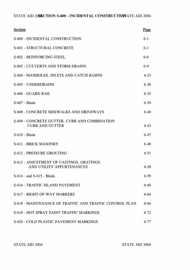
STATE AID 2004 STATE AID 2004
STATE AID 2004 STATE AID 2004
SECTION S-600 - INCIDENTAL CONSTRUCTION
Section Page
S-600 - INCIDENTAL CONSTRUCTION 6-1
S-601 - STRUCTURAL CONCRETE 6-1
S-602 - REINFORCING STEEL 6-6
S-603 - CULVERTS AND STORM DRAINS 6-9
S-604 - MANHOLES, INLETS AND CATCH BASINS 6-23
S-605 - UNDERDRAINS 6-28
S-606 - GUARD RAIL 6-35
S-607 - Blank 6-39
S-608 - CONCRETE SIDEWALKS AND DRIVEWAYS 6-40
S-609 - CONCRETE GUTTER, CURB AND COMBINATION CURB AND GUTTER 6-43
S-610 - Blank 6-47
S-611 - BRICK MASONRY 6-48
S-612 - PRESSURE GROUTING 6-51
S-613 - ADJUSTMENT OF CASTINGS, GRATINGS AND UTILITY APPURTENANCES 6-58
S-614 - and S-615 - Blank. 6-59
S-616 - TRAFFIC ISLAND PAVEMENT 6-60
S-617 - RIGHT-OF-WAY MARKERS 6-64
S-618 - MAINTENANCE OF TRAFFIC AND TRAFFIC CONTROL PLAN 6-66
S-619 - HOT SPRAY PAINT TRAFFIC MARKINGS 6-72
S-620 - COLD PLASTIC PAVEMENT MARKINGS 6-77
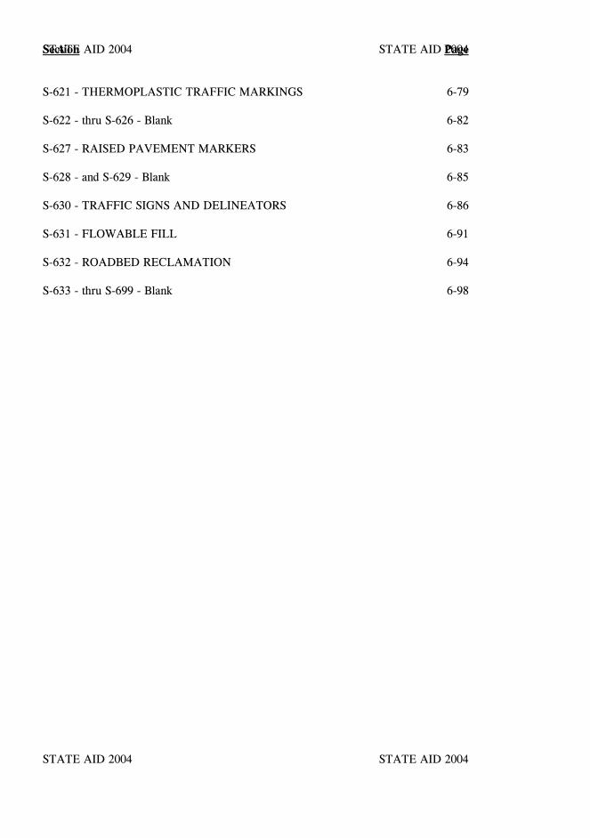
STATE AID 2004 STATE AID 2004
STATE AID 2004 STATE AID 2004
Section Page
S-621 - THERMOPLASTIC TRAFFIC MARKINGS 6-79
S-622 - thru S-626 - Blank 6-82
S-627 - RAISED PAVEMENT MARKERS 6-83
S-628 - and S-629 - Blank 6-85
S-630 - TRAFFIC SIGNS AND DELINEATORS 6-86
S-631 - FLOWABLE FILL 6-91
S-632 - ROADBED RECLAMATION 6-94
S-633 - thru S-699 - Blank 6-98
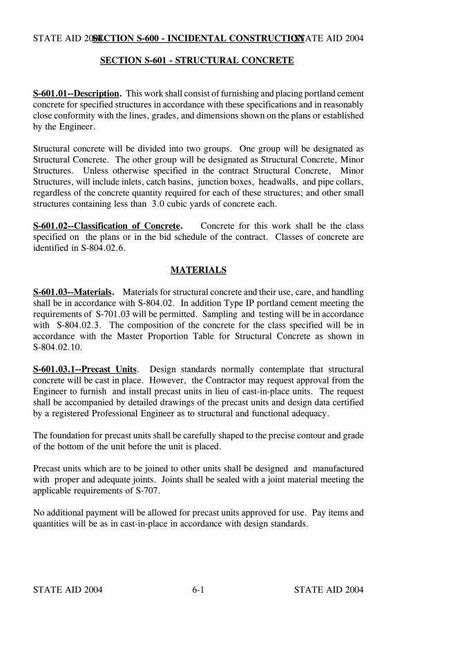
STATE AID 2004 STATE AID 2004
STATE AID 2004 STATE AID 20046-1
SECTION S-600 - INCIDENTAL CONSTRUCTION
SECTION S-601 - STRUCTURAL CONCRETE
S-601.01--Description. This work shall consist of furnishing and placing portland cementconcrete for specified structures in accordance with these specifications and in reasonablyclose conformity with the lines, grades, and dimensions shown on the plans or establishedby the Engineer.
Structural concrete will be divided into two groups. One group will be designated asStructural Concrete. The other group will be designated as Structural Concrete, MinorStructures. Unless otherwise specified in the contract Structural Concrete, MinorStructures, will include inlets, catch basins, junction boxes, headwalls, and pipe collars,regardless of the concrete quantity required for each of these structures; and other smallstructures containing less than 3.0 cubic yards of concrete each.
S-601.02--Classification of Concrete. Concrete for this work shall be the classspecified on the plans or in the bid schedule of the contract. Classes of concrete areidentified in S-804.02.6.
MATERIALS
S-601.03--Materials. Materials for structural concrete and their use, care, and handlingshall be in accordance with S-804.02. In addition Type IP portland cement meeting therequirements of S-701.03 will be permitted. Sampling and testing will be in accordancewith S-804.02.3. The composition of the concrete for the class specified will be inaccordance with the Master Proportion Table for Structural Concrete as shown inS-804.02.10.
S-601.03.1--Precast Units. Design standards normally contemplate that structuralconcrete will be cast in place. However, the Contractor may request approval from theEngineer to furnish and install precast units in lieu of cast-in-place units. The requestshall be accompanied by detailed drawings of the precast units and design data certifiedby a registered Professional Engineer as to structural and functional adequacy.
The foundation for precast units shall be carefully shaped to the precise contour and gradeof the bottom of the unit before the unit is placed.
Precast units which are to be joined to other units shall be designed and manufacturedwith proper and adequate joints. Joints shall be sealed with a joint material meeting theapplicable requirements of S-707.
No additional payment will be allowed for precast units approved for use. Pay items andquantities will be as in cast-in-place in accordance with design standards.

STATE AID 2004 STATE AID 2004
STATE AID 2004 STATE AID 20046-2
SECTION S-601 SECTION S-601
CONSTRUCTION REQUIREMENTS
S-601.04--Composition of Concrete. The composition of the concrete shall be inaccordance with S-804.02.
S-601.05--Batching. Measuring and batching of component materials shall be inaccordance with the applicable provisions of S-804.
S-601.06--Mixing and Conveying Concrete. Concrete shall be mixed and conveyed inaccordance with the applicable provisions of S-804.03.
S-601.07--Cold or Hot Weather Concreting. Requirements for placement, protection,and curing of concrete during cold or hot weather are stipulated in S-804.03.16.
S-601.08--Consistency. The slump of the concrete, determined in accordance with theprovisions of S-700.03, shall conform to the applicable requirements of S-804.
S-601.09--Falsework and Forms.
S-601.09.1--Falsework. Falsework shall be in accordance with the applicable provisionsof S-804.03.13.
S-601.09.2--Forms. Forms shall conform to the requirements of S-804.03.14.
S-601.09.3--Removal of Falsework, Forms, and Housing. The removal offalsework, forms, and the discontinuance of heating, shall be in accordance with theprovisions and requirements of S-804.03.15, and in addition shall conform to thefollowing age or cylinder strength requirements:
Column A Column BWingwall and WallForms not under Stress 24 to 48 hours*, minimum 1,000 psi
Wall Forms under Stress 7 days, minimum 2,200 psi
Backfill and Cover 3 days per foot clear 2,400 psispan or clear height,whichever is the greater(10 days minimum)
* As directed by the Engineer.
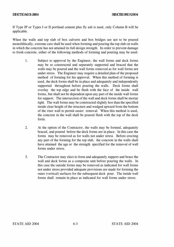
STATE AID 2004 STATE AID 2004
STATE AID 2004 STATE AID 20046-3
SECTION S-601 SECTION S-601
If Type IP or Types I or II portland cement plus fly ash is used, only Column B will beapplicable.
When the walls and top slab of box culverts and box bridges are not to be pouredmonolithically, extreme care shall be used when forming and pouring the top slab on wallsin which the concrete has not attained its full design strength. In order to prevent damageto fresh concrete, either of the following methods of forming and pouring may be used:
1. Subject to approval by the Engineer, the wall forms and deck formsmay be so constructed and separately supported and braced that thewalls may be poured and the wall forms removed as for wall forms notunder stress. The Engineer may require a detailed plan of the proposedmethod of forming for his approval. When this method of forming isused, the deck forms shall be in place and adequately and independentlysupported throughout before pouring the walls. Deck forms shalloverlay the top edge and be flush with the face of the inside wallforms, but shall not be dependent upon any part of the inside wall formsfor support. The intersection of the wall and deck forms shall be mortartight. The wall forms may be constructed slightly less than the specifiedinside clear height of the structure and wedged upward from the bottomof the riser wall to permit easier removal. When this method is used,the concrete in the wall shall be poured flush with the top of the deckform.
2. At the option of the Contractor, the walls may be formed, adequatelybraced, and poured before the deck forms are in place. In this case theforms may be removed as for walls not under stress. Before erectingany part of the forming for the top slab, the concrete in the walls shallhave attained the age or the strength specified for the removal of wallforms under stress.
3. The Contractor may elect to form and adequately support and brace thewall and deck forms as a composite unit before pouring the walls. Inthis case the outside forms may be removed as indicated for wall formsnot under stress provided adequate provisions are made for forming theouter (vertical) surfaces for the subsequent deck pour. The inside wallforms shall remain in place as indicated for wall forms under stress.
STATE AID 2004 STATE AID 2004
STATE AID 2004 STATE AID 20046-4
SECTION S-601 SECTION S-601
S-601.09.4--Damage to Previously Placed Concrete. In the event previously placedconcrete is damaged, all work on the affected structure shall cease immediately for anengineering assessment of the damage and the corrective work to be performed. Noadditional work shall be performed until this determination has been made, and theEngineer has given the Contractor approval to proceed with the corrective work andsubsequent construction. All corrective work required shall be performed by theContractor at no additional cost to the Project.
S-601.10--Foundations and Footings. Foundations for structures shall be prepared inaccordance with the requirements and provisions of S-206.
All footings shall be poured "dry". Where footings can be placed in the "dry" withoutthe use of cribs or cofferdams, the Engineer may permit back forms to be omitted, andconcrete poured against the faces of the excavation.
S-601.11--Placing Reinforcing Steel. Reinforcing steel shall be placed in accordancewith the requirements of S-602 and as shown on the plans.
S-601.12--Handling and Placing Concrete. Handling and placing concrete shall be inaccordance with the provisions of S-804.03.6.
S-601.13--Expansion and Fixed Joints. All expansion and fixed joints shall conform tothe applicable provisions of S-804.03.18.
S-601.14--Finishing Concrete Surfaces. Unless otherwise authorized, the surface of theconcrete shall be finished immediately after form removal.
Surface finishes shall conform to the applicable provisions of S-804.03.19.
S-601.15--Curing Concrete. Concrete shall be cured in accordance with the provisionsof S-804.03.17.
COMPENSATION
S-601.16--Method of Measurement. Accepted quantities of structural concrete will bemeasured by the cubic yard. Except for changes ordered in writing by the Engineer, theneat dimensions shown on the plans will be used for computing volumes. The quantityof concrete in fillets, scorings, and chamfers one square inch or less in cross section areawill be neglected in measurements.

STATE AID 2004 STATE AID 2004
STATE AID 2004 STATE AID 20046-5
SECTION S-601 SECTION S-601
No deductions will be made for the volume of concrete displaced by reinforcement, pipeor other conduits less than eight inches in nominal diameter, pipe posts, structural steelposts, or joint material.
When both Pay Item Numbers S-601-A and S-601-B are included in the contract,measurement of concrete for Pay Item No. S-601-B will be limited to inlets, catch basins,junction boxes, headwalls, and pipe collars, regardless of the concrete quantity requiredfor each of these structures; and other small structures containing less than three cubicyards.
S-601.17--Basis of Payment. Structural concrete will be paid for at the contract unitprice per cubic yard which shall be full compensation for completing the work specified.
Payment will be made under:
S-601-A: Class Structural Concrete - per cubic yard
S-601-B: Class Structural Concrete, Minor Structures - per cubic yard
STATE AID 2004 STATE AID 2004
STATE AID 2004 STATE AID 20046-6
SECTION S-602 - REINFORCING STEEL
S-602.01--Description. This work shall consist of furnishing and placing reinforcing steelin accordance with these specifications and in reasonably close conformity with thedimension, bending, spacing, and other requirements shown on the plans.
MATERIALS
S-602.02--Material Requirements. Reinforcing steel shall conform with therequirements of S-711 and S-805.02.
CONSTRUCTION REQUIREMENTS
S-602.03--Bar List and Order Lists. The bar lists and bending schedules shown on theplans are primarily for the purpose of estimating quantities. Lengths of box culverts andbox bridges, and depths of inlets, etc. shown on the plans are also approximate. TheContractor shall verify the quantity, size, and shape of the reinforcement for compliancewith the structural drawings and make the necessary corrections, if any, before ordering.In the case of box culverts, box bridges, inlets, etc.; verification shall be made after theEngineer has furnished the Contractor with a list of the staked lengths or depths forstructures. Errors in the bar list and bending schedule shall not be cause for adjustmentof the contract unit price, and the Contractor shall be fully responsible for all expensescaused by his failure to furnish the proper size, shape, length, and quantity of reinforcingsteel required.
When stipulated in the contract, or at the option of the Contractor when not stipulated,order lists and bending diagrams shall be furnished by the Contractor to the Engineer forapproval. In these cases no materials shall be ordered until the lists and bending diagramshave been approved. The approval of order lists and bending diagrams by the Engineerwill in no way relieve the Contractor of the responsibility for the correctness of the listsand diagrams. All expense incidental to the revision of materials furnished in accordancewith such lists and diagrams to make them comply with the design drawings and lengthsas staked by the Engineer shall be borne by the Contractor.
S-602.04--Protection of Materials. Steel reinforcement shall be protected in accordancewith S-805.03.1.
STATE AID 2004 STATE AID 2004
STATE AID 2004 STATE AID 20046-7
SECTION S-602 SECTION S-602
S-602.05--Bending. Bending shall be in accordance with S-805.05.
S-602.06--Placing and Fastening. The steel reinforcement shall be accurately placed inthe positions shown on the plans and firmly held during the placing and setting ofconcrete. Bars shall be tied at all intersections, except where spacing is less than one footin each direction then alternate intersections shall be tied.
All reinforcing steel shall be securely spaced from the forms and between adjacentreinforcement by means of approved precast mortar blocks (of minimum size foradequacy) or metal spacers or devices. Where possible, all spacer devices shall bearranged so that they cannot be detected in the completed structure. Metal devices whichare in contact with the exterior surface of the concrete shall be one of the types specifiedin S-711.02.7. Gravel, pieces of broken stone or brick, metal pipe, and wooden blocksshall not be used for spacers or chairs.
Reinforcement shall be accurately and securely placed to the dimensions shown on theplans, with a tolerance of one-half inch, then inspected and approved by the Engineerprior to the placing of concrete. Concrete placed in violation of this provision may berejected and its removal required.
Substitution of different size bars will be permitted only with specific authorization by theEngineer. If steel is substituted, it shall have a cross sectional area equivalent to orgreater than the design area.
S-602.06.1--Splicing. Except where shown on the plans, splicing of bars will not bepermitted without the written approval of the Engineer. Splices, when permitted, shallbe staggered as far apart as possible.
Unless otherwise shown on the plans spliced bars shall be lapped twenty (20) diameters.In lapped splices, the bars shall be placed in contact and wired together in a manner thatwill maintain the minimum clear distance specified between bars and to the surface of theconcrete.
Welding of reinforcing steel will be permitted only if detailed on the plans or if authorizedby the Engineer in writing. If done, it shall conform to AWS Recommended Practicesfor Welding Reinforcing Steel, Metal Inserts, and Connections in Reinforced ConcreteConstruction.
S-602.06.2--Lapping of Mesh and Bar Mats. Sheets of mesh or bar mat reinforcementshall overlap each other sufficiently to maintain a uniform strength and shall be securelyfastened at the ends and edges. The edge lap shall be at least one mesh in width.
STATE AID 2004 STATE AID 2004
STATE AID 2004 STATE AID 20046-8
SECTION S-602 SECTION S-602
COMPENSATION
S-602.07--Method of Measurement. Complete and accepted steel reinforcement will bemeasured in pounds based on the computed weight of the reinforcement shown on theplans or authorized. In cases where a structure is measured and paid for by the unit,complete in place, no measurement of reinforcing steel will be made.
The weight of plain or deformed bars and bar mats will be computed from the weightsshown in the table of areas and weights in S-711.02.1.
The weight for payment of steel fabric reinforcement will be computed from thetheoretical weight of plain wire. If the weight per unit of area of the fabric is shown onthe plans, that weight will be used for measurement.
The weight for payment of structural steel reinforcement will be the theoretical weightof the material used.
No allowance will be made for clips, wire, separators, wire chairs, and other materialused in fastening the reinforcing in place. If bars are substituted upon the Contractor'srequest and as a result more steel is used than specified, only the quantity specified willbe measured.
When splice laps, other than those shown on the plans, are made for the convenience ofthe Contractor, the extra steel will not be included in the measurement.
S-602.08--Basis of Payment. Reinforcing steel will be paid for at the contract unit priceper pound which shall be full compensation for completing the work specified.
Payment will be made under:
S-602-A: Reinforcing Steel - per pound
STATE AID 2004 STATE AID 2004
STATE AID 2004 STATE AID 20046-9
SECTION S-603 - CULVERTS AND STORM DRAINS
S-603.01--Description. This work shall consist of the construction or reconstruction ofpipe culverts, precast box culverts, cattlepasses, storm drains, sewers, downspouts,special sections and headwalls, hereinafter referred to as "conduit," in accordance withthese specifications and in reasonably close conformity with the lines and grades shownon the plans or established. It shall also consist of furnishing all materials, except thosespecified to be furnished by the County, and joining the work to other conduit, catchbasins, manholes, inlets, etc., as may be required to complete the work as designated.
This work shall also consist of constructing conduits for the encasement of undergroundutilities or for other use by the method of jacking or boring in accordance with thesespecifications and in reasonably close conformity with the lines and grades specified onthe plans or established.
MATERIALS
S-603.02--Material Requirements. Conduit shall conform to the design and dimensionsshown on the plans, and materials shall meet the requirements specified in the followingsections or subsections:
Bituminous coated corrugated aluminum pipe and pipe arches . . . . . . . . S-709.11Bituminous coated corrugated metal pipe and pipe arches . . . . . . . . . . . S-709.03Bituminous coated paved invert corrugated aluminum pipe and pipe arches S-709.12Bituminous coated paved invert corrugated metal pipe and pipe arches . . S-709.04Bituminous plastic sealer for joints . . . . . . . . . . . . . . . . . . . . . . . . . S-707.05Cast iron pipe . . . . . . . . . . . . . . . . . . . . . . . . . . . . . . . . . . . . . . S-709.01Concrete arch pipe end sections . . . . . . . . . . . . . . . . . . . . . . . . . . . S-708.04Concrete for headwalls . . . . . . . . . . . . . . . . . . . . . . . . . . . . . . . . . S-601 Concrete pipe cattlepasses . . . . . . . . . . . . . . . . . . . . . . . . . . . . . . . S-708.03Corrugated aluminum pipe and pipe arches . . . . . . . . . . . . . . . . . . . . S-709.09Corrugated metal pipe and pipe arches . . . . . . . . . . . . . . . . . . . . . . . S-709.02Corrugated poly vinyl chloride (PVC) pipe . . . . . . . . . . . . . . . . . . . . S-708.17Corrugated polyethylene pipe . . . . . . . . . . . . . . . . . . . . . . . . . . . . S-708.17Elbows and branch connections for concrete pipe . . . . . . . . . . . . . . . S-708.23Flexible plastic gaskets for joints . . . . . . . . . . . . . . . . . . . . . . . . . . S-707.06Joint Mortar . . . . . . . . . . . . . . . . . . . . . . . . . . . . . . . . . . . . . . . . S-707.02Joints for sanitary sewers . . . . . . . . . . . . . . . . . . S-603.06, S-707.04, S-707.06Metal end sections, elbows, and branch connections . . . . . . . . . . . . . . S-709.18Non-reinforced concrete pipe . . . . . . . . . . . . . . . . . . . . . . . . . . . . . S-708.02Polymer coated corrugated metal pipe and pipe arches . . . . . . . . . . . . . S-709.05Precast box culverts . . . . . . . . . . . . . . . . . . . . . . . . . . . . . . . . . . . S-708.22Reinforced concrete arch pipe . . . . . . . . . . . . . . . . . . . . . . . . . . . . S-708.14Reinforced concrete elliptical pipe . . . . . . . . . . . . . . . . . . . . . . . . . . S-708.15
STATE AID 2004 STATE AID 2004
STATE AID 2004 STATE AID 20046-10
SECTION S-603 SECTION S-603
Reinforced concrete end sections . . . . . . . . . . . . . . . . . . . . . . . . . . S-708.04Reinforced concrete pipe . . . . . . . . . . . . . . . . . . . . . . . . . . . . . . . S-708.02Reinforcing steel . . . . . . . . . . . . . . . . . . . . . . . . . . . . . . . . . . . . . S-602 Rubber-type gaskets . . . . . . . . . . . . . . . . . . . . . . . . . . . . . . . . . . . S-707.04Steel pipe . . . . . . . . . . . . . . . . . . . . . . . . . . . . . . . . . . . . . . . . . S-709.19
When material requirements provide for modifications of design, acceptable modifieddesigns will be shown on the plans.
CONSTRUCTION REQUIREMENTS
S-603.03--Excavation. Except for conduit to be installed by jacking and boring, trenchesshall be excavated in accordance with the requirements of S-206 to a width sufficient toallow for proper jointing of the conduit and thorough compaction of the bedding andbackfill material under and around the conduit. Where feasible, trench walls shall bevertical.
The completed trench bottom shall be firm for its full length and width. Where required,in the case of cross drains, the trench shall have the camber specified.
Where conduit is to be placed in embankment, the excavation shall be made after theembankment has been completed to the specified height above the flow line of theconduit. In all cases the height above flow line shall be at least one foot.
In the case of pipe to be jacked or bored, only the trench excavation and bedding as setout in S-603.11 shall be performed.
S-603.04--Bedding. Except for conduit placed in a vertical position or jacked or bored,the conduit bedding shall conform to one of the classes specified. When no beddingclass is specified the requirements for Class C bedding or Class C modified bedding, asapplicable shall apply.
CLASS A bedding shall consist of a continuous concrete cradle conforming to the plandetails, and constructed on an approved foundation.

STATE AID 2004 STATE AID 2004
STATE AID 2004 STATE AID 20046-11
SECTION S-603 SECTION S-603
CLASS B bedding shall consist of bedding the conduit to a depth of at least thirty (30)percent of the vertical outside dimension of the conduit. The thickness of beddingmaterial beneath the pipe shall be at least four inches. The bedding material shall be sandor selected sandy soil, all of which passes a 3/8" sieve and not more than ten (10) percentof which passes a No. 200 sieve. The layer of bedding material shall be shaped to fit theconduit for at least fifteen (15) percent of its total height. Recesses in the trench bottomshall be shaped to accommodate the bell when bell and spigot type conduit is used.
CLASS C bedding shall consist of bedding the conduit to a depth of at least ten (10)percent of its total height. The bed shall be shaped to fit the conduit and shall haverecesses shaped to receive the bell if bell and spigot type pipe is used.
CLASS C MODIFIED bedding shall consist of bedding corrugated conduit to a depth ofat least ten (10) percent of its total height. A bedding blanket of approved silty loam,sandy loam, concrete sand, or other approved sand or sandy soil shall be roughly shapedto fit the bottom of the pipe. Minimum thickness before placing pipe shall be as follows:
1 inch for 1/2 inch deep corrugations2 inches for 1 inch deep corrugations3 inches for 2 inches or 2 1/2 inches corrugations
For structural plate pipe the length of bedding arc need not exceed the width of the bottomplate.
Bedding for precast concrete box culverts shall consist of at least two inches of granularmaterial (Class 9, Group C or better) placed between graded forms set at least one footoutside each outside wall of the box culvert. The granular material shall be shaped to fitthe bottom of the precast box culvert sections by screeding off the graded forms. Afterplacement of the precast box culvert sections on the graded bedding, the forms may beremoved and reused.

STATE AID 2004 STATE AID 2004
STATE AID 2004 STATE AID 20046-12
SECTION S-603 SECTION S-603
S-603.05--Laying Conduit. The conduit laying shall begin at the staked location of thedownstream end of the conduit line. The lower segment of the conduit shall be in contactwith the shaped bedding throughout its full length. Bell or groove ends of rigid conduitsand outside circumferential laps of flexible conduits shall be placed facing upstream.Flexible conduits shall be placed with longitudinal laps or seams at the sides.
Paved or partially lined conduit shall be laid so that the longitudinal center line of thepaved segment coincides with the flow line. Elliptical and elliptically reinforced conduitsshall be placed with the major axis within five degrees of a horizontal plane through thelongitudinal axis of the conduit.
Construction requirements for end sections shall conform to the requirements for placingthe pipe to which they are joined.
At the Contractor's option, subject to the written approval of the Engineer, concreteheadwalls conforming to the MDOT Standard Drawings may be substituted in lieu ofpremanufactured end sections without change in compensation.
S-603.06--Joining Conduit.
S-603.06.1--Storm Drainage. Rigid conduits may be either bell and spigot or tongueand groove design unless one type is specified. The method of joining conduit sectionsshall be such that the ends are fully entered, and the inner surfaces are reasonably flushand even. Unless otherwise specified, joints shall be sealed with preformed rubber-typegaskets, bituminous plastic sealer, or flexible plastic gaskets. When a specific type ofjoint sealer is required, it shall be indicated on the plans.
Joints for precast concrete box culverts shall be made with bituminous plastic sealer.
Rubber-type gaskets shall be installed so as to form a flexible watertight seal.
For joints to be sealed with bituminous plastic, the joining ends shall be wiped clean anddry. The plastic compound shall be applied cold to the entire surface of tongues andgrooves, the entire surface of bells and spigots, and the entire area of metal pipes to becovered by connecting bands. Sections of concrete pipe shall be forced together, andsections of metal pipe banded together, with excess compound extruding both inside andoutside the pipe. Excess compound shall be removed from interior surfaces, and theexterior shall be finished reasonably flush. After pipe has been joined with bituminousplastic compound, suitable kraft or other approved paper shall be placed over the outsidejoints to avoid mixing of soil with the compound.
STATE AID 2004 STATE AID 2004
STATE AID 2004 STATE AID 20046-13
SECTION S-603 SECTION S-603
For joints to be sealed with preformed plastic gasket material, the pipe shall be installedin a dry trench. Joints shall be made in such a manner that a slight internal extrusion ofthe plastic gasket will occur for the full circumference when the sections of pipe areforced together. Installation shall be in accordance with these specifications and themanufacturer's instructions. Plastic gasket material shall be applied only to surfaceswhich are dry. A primer of the type recommended by the manufacturer of the plasticgasket shall be applied to the tongue and groove and to the end surfaces, and the surfaceto be primed shall be clean and dry when the primer is applied.
During cold weather the joint surfaces and the gasket shall be lightly heated, withoutdamage to the pipe or joint material, immediately prior to forcing the sections of pipetogether. During hot weather the Contractor shall place kraft or other approved paperover the joints to avoid mixing soil with the plastic gasket material.
For joints constructed of either bituminous plastic sealer or preformed plastic material,special care shall be taken to provide an equal uniform joint between pipe sections and toprevent one section from supporting the other. Backfilling operations may followimmediately.
Flexible conduits shall be firmly joined by coupling bands. The ends of flexible conduitsfabricated with helical corrugations shall be adapted by reforming and/or modification forcircumferential corrugated coupling bands. The width and thickness of corrugated bandsfor both circumferential and helical corrugated flexible conduits shall be in accordancewith AASHTO Designation: M 36 except that the bands shall be no less than 10½ inchesin width.
In lieu of the preceding requirements and in addition to being supplied or recommendedby the pipe manufacturer, coupling bands for joining corrugated polyethylene pipe shallbe in accordance with AASHTO Designation: M 294 and shall meet or exceed thesoil-tightness requirements of the AASHTO Standard Specifications for Highway Bridges,Section 26, paragraph 26.4.2.4 (e).
Corrugated polyethylene pipe may also be furnished with bell & spigot type joints withO-ring rubber gasket meeting ASTM Designation: F 477 placed on the spigot end. Atleast two (2) corrugations of the spigot end must insert into the bell end.
Joints and fittings for poly (vinyl chloride) (PVC) pipe shall meet the requirements ofASTM Designation: F 949.

STATE AID 2004 STATE AID 2004
STATE AID 2004 STATE AID 20046-14
SECTION S-603 SECTION S-603
S-603.06.2–Pipes With Gaskets. Unless otherwise specified, joints for pipe requiringgaskets shall conform to the following:
(a) Pipes requiring gaskets shall be constructed to accommodate the gasket inaccordance with the recommendations of the manufacturer of the gasket. Rubbergaskets shall comply with S-707.04, and flexible plastic gaskets shall complywith S-707.06.
(b) In municipalities and other local governments having codes and specifications forjoining sanitary sewer conduit, the local codes and specifications shall beapplicable.
(c) Depending upon the type of pipe specified and the joint to be used, theContractor shall perform the joining in accordance with the recommendations ofthe manufacturer of the joint material to the extent that the line will be waterproofed both from infiltration and exfiltration insofar as is practicable. Evidenceof leakage shall be corrected immediately.
(d) Evidence of leakage or suspected leakage may be cause for requiring theContractor to perform testing to determine the leakage present. In the case ofsanitary sewer lines, leakage exceeding the tolerance permitted under the localgoverning code, or in the absence of such code the tolerances permitted by theMississippi Department of Environmental Quality, Office of Pollution Control,will not be allowed. Leakage in excess of the tolerances permitted shall becorrected by reworking the line as necessary. Retesting may be required ifdeemed by the Engineer to be indicated. All testing shall be at no additional costto the Project.
S-603.07--Relaid Pipe. These construction specifications shall equally apply to relaidconduits. In addition, conduit salvaged for relaying shall be cleaned of all foreignmaterial prior to reinstallation. All pipe damaged through carelessness or negligence onthe part of the Contractor shall be replaced by new pipe or approved pipe at no additionalcost to the project.
Pipe and end sections designated for removal and relaying shall be removed in accordancewith the provisions of S-202.04.
S-603.08--Field Strutting. Where required by the plans, the vertical diameter of roundflexible pipe shall be uniformly increased five percent by means of jacks applied after theentire line of pipe has been installed on the bedding but before backfilling. The verticalelongation shall be uniformly maintained by means of sufficient sills and struts or bysufficient horizontal ties as specified. Only horizontal ties shall be used for paved invertpipe.
Unless otherwise directed, ties and struts shall be left in place until the embankment iscompleted and compacted.
STATE AID 2004 STATE AID 2004
STATE AID 2004 STATE AID 20046-15
SECTION S-603 SECTION S-603
S-603.09--Backfilling. Conduit shall be inspected before backfill is placed. Conduitfound to be out of alignment, unduly settled, or damaged shall be taken up and relaidor replaced. After approval of conduit, it shall be backfilled with specified material inaccordance with S-203.09.3.3.
S-603.10--Imperfect Trench. Under this method the embankment shall be completedto a height above the conduit equal to the vertical outside diameter of the conduit plus onefoot. A trench equal in width to the outside horizontal diameter of the conduit shall thenbe excavated to within one foot of the top of the conduit with the trench walls being asnearly vertical as possible. This trench shall be loosely filled with highly compactiblesoil. Straw, hay, corn stalks, leaves, brush, or sawdust may be used to fill the lowerone-fourth to one-third of the trench. Construction of the remainder of the embankmentshall then proceed in a normal manner.
S-603.11--Pipes and Encasements Jacked or Bored. No pipe shall be placed by jackingor boring unless so designated in the contract.
When jacking or boring is designated, the area of placement shall be carefullyinvestigated so as not to interfere with existing underground utilities. Care shall also betaken to keep the disturbed area of construction to a minimum.
The Engineer will establish line and grade and the limits, if any, of placement to be madeby conventional (open trench) methods for each line of pipe. Unless otherwise shown onthe plans, sections of steel pipe shall be joined by welding for the full circumference ofthe pipe to form a continuous, rigid, watertight structure of the required length. Weldingshall be performed in accordance with S-810.03.5.
S-603.11.1--Jacking. The designated strength of the pipe to be jacked is determined forthe final loading under the embankment. Additional reinforcement or strength of piperequired to withstand jacking pressure shall be the responsibility of the Contractor. Extrastrength pipe furnished by the Contractor shall be at no additional cost to the project.
Pipe larger than 3 1/2 inches ID shall not be pushed or jacked without boring or otherwiseremoving the soil as the pipe is advanced.
When required, suitable pits or trenches shall be excavated for the jacking operation andfor placing the end joints of pipe. Where necessary, they shall be securely sheeted andbraced to prevent caving.
Where pipe is required to be installed under railroads, highways, streets or other facilitiesby jacking or boring methods, construction shall be done in a manner that will notinterfere with the operation of the facility or weaken the roadbed or structure.
STATE AID 2004 STATE AID 2004
STATE AID 2004 STATE AID 20046-16
SECTION S-603 SECTION S-603
Jacks for forcing the pipe through the roadbed shall have a jacking head constructed insuch a manner as to apply uniform pressure around the ring of the pipe. The pipe to bejacked shall be set on guides braced together to properly support the section of the pipeand direct it to the proper line and grade. In general, roadbed material shall be excavatedjust ahead of the pipe, the excavated material removed through the pipe, and the pipe thenforced through the roadbed into the excavated space.
When requested, the Contractor shall furnish for the Engineer's approval, a plan showinghis proposed method of handling. The plan shall include the design for the jacking head,and show the jacking support or back stop, arrangement and position of jacks, pipeguides, etc., complete in assembled position. The approval of this plan by the Engineerwill not relieve the Contractor from his responsibility to obtain the specified results.
The diameter of the excavation shall conform to the outside circumference of the pipe asclosely as practicable. Voids which develop during the installation operation and whichare determined by the Engineer to be detrimental to the work shall be pressure groutedwith an approved mix.
The distance that the excavation extends beyond the end of the pipe will depend upon thecharacter of the excavated material, but shall not exceed two feet in any case. Thisdistance shall be decreased on instructions from the Engineer if the character of thematerial being excavated makes it desirable.
The pipe shall be jacked from the low or downstream end. Variation in the final positionof the pipe from the line and grade established by the Engineer will be permitted only tothe extent of two percent in lateral alignment and one percent in vertical grade, providedthat the final grade of flow line is in the direction designated.
If the Contractor desires, he may use a cutting edge around the head end which extendsa short distance beyond the pipe end and has inside angles or lugs to keep the cutting edgefrom slipping back into the pipe.
Once jacking of pipe has begun, the operation shall be carried on without interruption,insofar as practicable, to prevent the pipe from becoming firmly set in the embankment.
All pipe damaged in jacking operations shall be removed and replaced by the Contractorat their expense.
Pits or trenches excavated to facilitate jacking operations shall be backfilled immediatelyafter the jacking has been completed.
STATE AID 2004 STATE AID 2004
STATE AID 2004 STATE AID 20046-17
SECTION S-603 SECTION S-603
S-603.11.2--Boring. The boring shall proceed from a pit provided for the boringequipment and workmen. Excavation for pits and installation of shoring shall be asoutlined under jacking. The location of the pit shall meet the approval of the Engineer.The holes are to be bored mechanically. The boring shall be done using a pilot hole. Bythis method an approximate two inch pilot hole shall be bored the entire length of thecrossing and shall be checked for line and grade on the opposite end of the bore from thework pit. This pilot hole, when approved, shall serve as the centerline of the largerdiameter hole to be bored. Excavated material shall be placed near the top of theworking pit and disposed of as required. The use of water or other fluids in connectionwith the boring operation will be permitted only to the extent to lubricate cuttings asprovided herein. Jetting will not be permitted.
In unconsolidated soil formations, a gel-forming colloidal drilling fluid consisting of atleast ten (10) percent of high grade carefully processed bentonite may be used toconsolidate cuttings of the bit, seal the walls of the hole, and furnish lubrication forsubsequent removal of cuttings and installation of the pipe immediately thereafter.
Allowable variation from line and grade shall be as specified under jacking. Precisemeasures are to be taken to prevent overcutting. Overcutting in excess of one-half inchshall be remedied by pressure grouting.
S-603.11.3--Grouting, Backfilling, and Cleanup. After the jacked conduit is in place,all joints in concrete pipe shall be cleaned carefully and pointed from the inside to afforda smooth continuous interior surface.
Extension of the line beyond that required to be jacked or bored shall be by conventionalmethods as set out in this section.
As soon after jacking as possible, the interstices around the outside of the pipe shall befilled by pressure grouting. The grout mixture shall consist of fine sand or silt, TypeI cement of not less than fifteen (15) percent of volume, and water. The grout shall beplaced through holes bored at such intervals that the grout can be determined as risingin an adjacent hole at least six inches above the top of the pipe. The water content of thegrout shall be the minimum necessary to provide proper placement. Grouting shall beperformed by qualified personnel with equipment especially designed for the purpose.
At the end of each day's grouting operation, or at the completion of the grouting operationfor each line of pipe, whichever occurs first, the conduit shall be carefully inspected onthe inside and all grout which has penetrated the pipe shall be removed and the insidesurface wiped clean. Other waste grout which will impair the work shall be removed anddisposed of at on-project sites as designated by the Engineer.
STATE AID 2004 STATE AID 2004
STATE AID 2004 STATE AID 20046-18
SECTION S-603 SECTION S-603
After successive operations are completed, all sheeting, shoring, etc., shall be removed,excavations backfilled to the surface of the existing ground or as directed, the backfillcompacted in accordance with the specifications, and all surplus material disposed of aton-project sites as designated by the Engineer.
COMPENSATION
S-603.12--Method of Measurement. The lengths of pipe and precast box culverts,complete in place, will be measured by the linear foot by multiplying the number ofcommercial lengths by the nominal length per section; except, portions of commerciallengths extending more than four feet beyond the staked ends of the conduit will not bemeasured for payment.
Unless otherwise indicated on the plans, sections of lines of conduits placed byconventional methods will not be measured as pipe jacked or bored.
End sections, headwalls, elbows, branch connections, and other appurtenances for whichpay items are listed will be measured by the number of units of the kind and sizespecified.
Pipe removed and relaid will be measured by the linear foot. End sections removed andrelaid will be measured per each.
Excavation for conventionally installed conduits will be measured and paid for as set outin S-206. Excavation for conduits placed by jacking or boring will not be measured forseparate payment.
Excavation for precast box culverts will be measured in cubic yards as set out in S-206for cast-in-place box culverts of comparable sizes.
S-603.13--Basis of Payment. Accepted quantities of pipe and precast box culverts willbe paid for at the contract unit price per linear foot.
End sections, headwalls, elbows, branch connections, and other appurtenances for whichpay items are listed in the contract will be paid for at the contract unit price per each.
Pipe removed and relaid will be paid for at the contract unit price per linear foot. Endsections removed and relaid will be paid for at the contract unit price per each.
The prices thus paid shall be full compensation for completing the work specified.Materials or work for which a pay item is not included and are necessary to complete thework under this section shall be furnished or performed and shall be considered incidentalto the completed construction.
STATE AID 2004 STATE AID 2004
STATE AID 2004 STATE AID 20046-19
SECTION S-603 SECTION S-603
FERROUS METAL CONDUIT
Payment will be made under:
S-603-A: “ Steel Pipe, Wall Thickness - per linear foot
S-603-B: “ Cast Iron Pipe, Class , - per linear foot (Description)
CONCRETE CONDUIT
S-603-C-A: “ Reinforced Concrete Pipe, Class - per linear foot
S-603-C-B: “ Reinforced Concrete Pipe, End Section - per each
S-603-C-C: “ Non-Reinforced Concrete Pipe, Class - per linear foot
S-603-C-D: “ x “ Reinforced Concrete Arch Pipe, Class - per linear foot
S-603-C-E: “ x “ Reinforced Concrete Arch Pipe, End Section - per each
S-603-C-F: 48 “ x 72 “ Reinforced Concrete Pipe Cattlepass - per linear foot
For conduit required to be jacked or bored, the appropriate pay item listed above willcontain the term (Jacked or Bored), (Jacked) or (Bored), as applicable.
CORRUGATED FERROUS METAL CONDUIT
S-603-M-A: “ * Coated Corrugated Metal Pipe, Gage, Corrugation - per linear foot
S-603-M-B: “ * Coated Corrugated Metal End Section, Gage - per each
S-603-M-C: “ x “ * Coated Corrugated Metal Arch Pipe, Gage, Corrugation - per linear foot
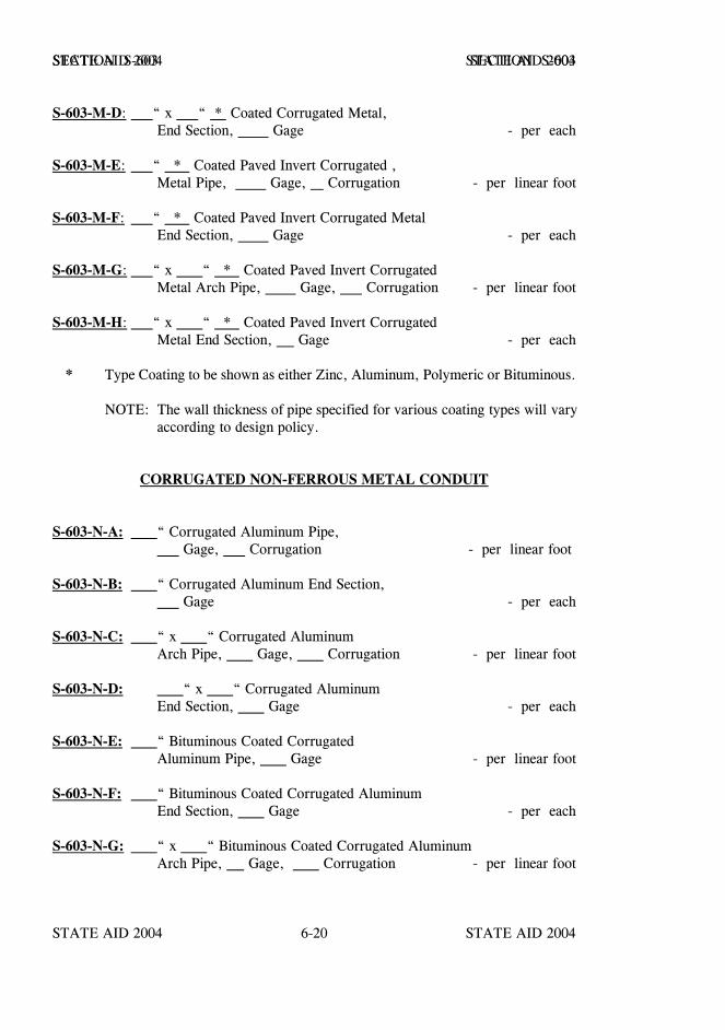
STATE AID 2004 STATE AID 2004
STATE AID 2004 STATE AID 20046-20
SECTION S-603 SECTION S-603
S-603-M-D: “ x “ * Coated Corrugated Metal,End Section, Gage - per each
S-603-M-E: “ * Coated Paved Invert Corrugated ,Metal Pipe, Gage, Corrugation - per linear foot
S-603-M-F: “ * Coated Paved Invert Corrugated Metal End Section, Gage - per each
S-603-M-G: “ x “ * Coated Paved Invert Corrugated Metal Arch Pipe, Gage, Corrugation - per linear foot
S-603-M-H: “ x “ * Coated Paved Invert Corrugated Metal End Section, Gage - per each
* Type Coating to be shown as either Zinc, Aluminum, Polymeric or Bituminous.
NOTE: The wall thickness of pipe specified for various coating types will varyaccording to design policy.
CORRUGATED NON-FERROUS METAL CONDUIT
S-603-N-A: “ Corrugated Aluminum Pipe, Gage, Corrugation - per linear foot
S-603-N-B: “ Corrugated Aluminum End Section, Gage - per each
S-603-N-C: “ x “ Corrugated Aluminum Arch Pipe, Gage, Corrugation - per linear foot
S-603-N-D: “ x “ Corrugated Aluminum End Section, Gage - per each
S-603-N-E: “ Bituminous Coated Corrugated Aluminum Pipe, Gage - per linear foot
S-603-N-F: “ Bituminous Coated Corrugated Aluminum End Section, Gage - per each
S-603-N-G: “ x “ Bituminous Coated Corrugated Aluminum Arch Pipe, Gage, Corrugation - per linear foot

STATE AID 2004 STATE AID 2004
STATE AID 2004 STATE AID 20046-21
SECTION S-603 SECTION S-603
S-603-N-H: “ x “ Bituminous Coated Corrugated Aluminum End Section, Gage - per each
S-603-N-I: “ Bituminous Coated Paved Invert, CorrugatedAluminum Pipe, Gage, Corrugation - per linear foot
S-603-N-J: “ Bituminous Coated Paved Invert, CorrugatedAluminum End Section, Gage - per each
S-603-N-K: “ x “ Bituminous Coated Paved Invert, CorrugatedAluminum Arch Pipe, Gage, Corrugation- per linear foot
S-603-N-L: “ x “ Bituminous Coated Paved Invert, CorrugatedAluminum End Section, Gage - per each
CORRUGATED POLYETHYLENE CONDUIT
S-603-PE: " Corrugated Polyethylene Pipe - per linear foot
S-603-PF: " Corrugated Polyethylene Pipe, End Section - per each
CORRUGATED POLY VINYL CHLORIDE CONDUIT
S-603-PVC: " Corrugated Poly Vinyl Chloride Pipe - per linear foot
PRECAST BOX CULVERTS
S-603-P-A: ' x ' Precast Concrete Box Culvert - per linear foot
S-603-P-B: ' x ' Precast Concrete Box Culvert End Section - per each
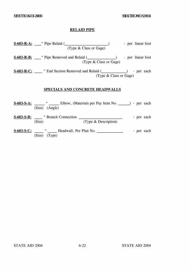
STATE AID 2004 STATE AID 2004
STATE AID 2004 STATE AID 20046-22
SECTION S-603 SECTION S-603
RELAID PIPE
S-603-R-A: “ Pipe Relaid ( ) - per linear foot (Type & Class or Gage)
S-603-R-B: “ Pipe Removed and Relaid ( ) - per linear foot(Type & Class or Gage)
S-603-R-C: “ End Section Removed and Relaid ( ) - per each(Type & Class or Gage)
SPECIALS AND CONCRETE HEADWALLS
S-603-S-A: “ Elbow, (Materials per Pay Item No. ) - per each(Size) (Angle)
S-603-S-B: “ Branch Connection - per each(Size) (Type & Description)
S-603-S-C: “ Headwall, Per Plan No. - per each(Size) (Type)
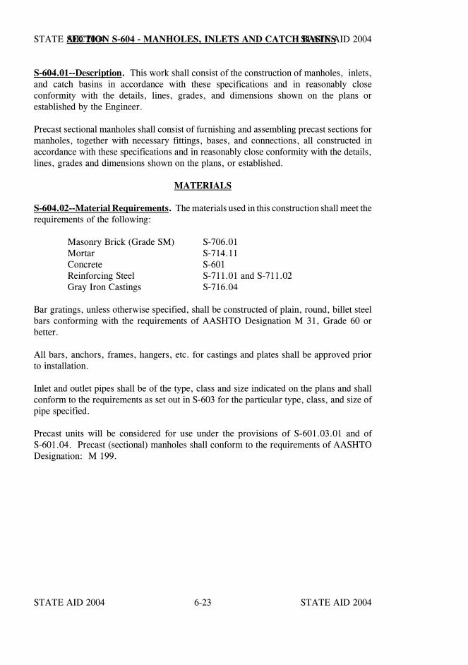
STATE AID 2004 STATE AID 2004
STATE AID 2004 STATE AID 20046-23
SECTION S-604 - MANHOLES, INLETS AND CATCH BASINS
S-604.01--Description. This work shall consist of the construction of manholes, inlets,and catch basins in accordance with these specifications and in reasonably closeconformity with the details, lines, grades, and dimensions shown on the plans orestablished by the Engineer.
Precast sectional manholes shall consist of furnishing and assembling precast sections formanholes, together with necessary fittings, bases, and connections, all constructed inaccordance with these specifications and in reasonably close conformity with the details,lines, grades and dimensions shown on the plans, or established.
MATERIALS
S-604.02--Material Requirements. The materials used in this construction shall meet therequirements of the following:
Masonry Brick (Grade SM) S-706.01Mortar S-714.11Concrete S-601Reinforcing Steel S-711.01 and S-711.02Gray Iron Castings S-716.04
Bar gratings, unless otherwise specified, shall be constructed of plain, round, billet steelbars conforming with the requirements of AASHTO Designation M 31, Grade 60 orbetter.
All bars, anchors, frames, hangers, etc. for castings and plates shall be approved priorto installation.
Inlet and outlet pipes shall be of the type, class and size indicated on the plans and shallconform to the requirements as set out in S-603 for the particular type, class, and size ofpipe specified.
Precast units will be considered for use under the provisions of S-601.03.01 and ofS-601.04. Precast (sectional) manholes shall conform to the requirements of AASHTODesignation: M 199.

STATE AID 2004 STATE AID 2004
STATE AID 2004 STATE AID 20046-24
SECTION S-604 SECTION S-604
CONSTRUCTION REQUIREMENTS
S-604.03--Construction Details.
S-604.03.1--Brick Masonry. Brick masonry shall be constructed in conformity with thedetails shown on the plans and in accordance with the provisions of S-611.
Where irons or other fittings enter the brick work, they shall be placed as the work is laidup, thoroughly bonded, accurately spaced, and lined. Upon completion of the masonryand setting of castings and fittings, the inside and outside surfaces of the masonry shallbe neatly plastered with mortar 1/2 inch thick. Plastering shall have a uniform, smoothfinish and shall be neatly pointed to all fittings.
S-604.03.2--Concrete Masonry. Unless otherwise specified, concrete masonry shall beconstructed of Class "B" concrete in accordance with the requirements of S-601.
S-604.03.3--Reinforcement. Reinforcement shall be placed as indicated on the plans oras directed and in accordance with the provisions of S-602.
S-604.03.4--Optional Construction. When plan standards indicate portions of thestructure may be constructed of either brick masonry or concrete, the Contractor may useeither concrete or brick masonry for these portions, provided the plan dimensions for wallthickness, etc. are maintained. In either case the masonry, whether concrete or brick,will be measured for payment as stipulated in S-604.04.
S-604.03.5--Inlet and Outlet Pipes. Unless otherwise directed, inlet and outlet pipesshall extend through the walls of manholes and catch basins for a sufficient distancebeyond the outside surface to allow for connections and shall be cut flush with the wallon the inside surface and neatly pointed.
The concrete, or brick and mortar, shall be constructed around the pipes so as to preventleakage and to form a neat connection.
S-604.03.6--Castings, Gratings, and Fittings. All castings and gratings shall becarefully handled. Injurious cracks, chips, surface mars, etc. which render themunsuitable for use or unsightly after being placed will be cause for rejection, and if sodirected they shall be replaced.
The castings, gratings, and fittings shall be placed as indicated on the plans or as directedto line and grade and in such a manner that subsequent adjustments will not be necessary.
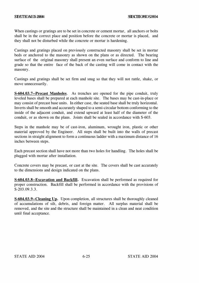
STATE AID 2004 STATE AID 2004
STATE AID 2004 STATE AID 20046-25
SECTION S-604 SECTION S-604
When castings or gratings are to be set in concrete or cement mortar, all anchors or boltsshall be in the correct place and position before the concrete or mortar is placed, andthey shall not be disturbed while the concrete or mortar is hardening.
Castings and gratings placed on previously constructed masonry shall be set in mortarbeds or anchored to the masonry as shown on the plans or as directed. The bearingsurface of the original masonry shall present an even surface and conform to line andgrade so that the entire face of the back of the casting will come in contact with themasonry.
Castings and gratings shall be set firm and snug so that they will not rattle, shake, ormove unnecessarily.
S-604.03.7--Precast Manholes. As trenches are opened for the pipe conduit, trulyleveled bases shall be prepared at each manhole site. The bases may be cast-in-place ormay consist of precast base units. In either case, the seated base shall be truly horizontal.Inverts shall be smooth and accurately shaped to a semi-circular bottom conforming to theinside of the adjacent conduit, and extend upward at least half of the diameter of theconduit, or as shown on the plans. Joints shall be sealed in accordance with S-603.
Steps in the manhole may be of cast-iron, aluminum, wrought iron, plastic or othermaterial approved by the Engineer. All steps shall be built into the walls of precastsections in straight alignment to form a continuous ladder with a maximum distance of 16inches between steps.
Each precast section shall have not more than two holes for handling. The holes shall beplugged with mortar after installation.
Concrete covers may be precast, or cast at the site. The covers shall be cast accuratelyto the dimensions and design indicated on the plans.
S-604.03.8--Excavation and Backfill. Excavation shall be performed as required forproper construction. Backfill shall be performed in accordance with the provisions ofS-203.09.3.3.
S-604.03.9--Cleaning Up. Upon completion, all structures shall be thoroughly cleanedof accumulations of silt, debris, and foreign matter. All surplus material shall beremoved, and the site and the structure shall be maintained in a clean and neat conditionuntil final acceptance.
STATE AID 2004 STATE AID 2004
STATE AID 2004 STATE AID 20046-26
SECTION S-604 SECTION S-604
COMPENSATION
S-604.04--Method of Measurement. When either concrete masonry or brick masonryis permitted, and when concrete is specified, measurement will be by the cubic yard inaccordance with S-601.16 for Structural Concrete - Minor Structures.
Precast manholes will be measured per linear foot of depth from the flowline of themanhole to the top of the cover, or as indicated on the plans.
Reinforcing steel will be measured per pound in accordance with S-602.07.
When brick masonry only is specified, measurement will be by the cubic yard or perthousand (M) brick in accordance with S-611.06.
Excavation will not be measured for payment as a separate item. The cost of excavationshall be included in the unit price bid for concrete or brick masonry.
Castings, gratings and metallic manhole covers will be computed in pounds from thedimensions shown on the plans and based on the unit weights of metals set out inS-810.04.4.
Fittings will not be measured for separate payment. Their cost shall be included in theprice bid for concrete or brick masonry.
S-604.05--Basis of Payment. Structural concrete, reinforcing steel, and brick masonrywill be paid for at the respective contract unit price in accordance with S-601.17,S-602.08, or S-611.07 as applicable.
Precast Manholes will be paid for at the contract bid price per linear foot of depth, whichprice shall be full compensation for all necessary excavation, sheeting, cribbing, shoring,bracing, well-pointing, furnishing and assembling all elements of the manhole includingconcrete bases & covers except metallic cover and frame, for all other items of worknecessary and incident to the complete construction and for all equipment, labor, tools andincidentals necessary to complete the work.

STATE AID 2004 STATE AID 2004
STATE AID 2004 STATE AID 20046-27
SECTION S-604 SECTION S-604
Castings and gratings will be paid for at the contract unit price per pound for castings orgratings, complete in place. These prices shall be full compensation for completing thework specified.
Payment will be made under:
S-604-A: Castings - per pound
S-604-B: Gratings - per pound
S-604-C: Precast Manhole, " Diameter - per linear foot
STATE AID 2004 STATE AID 2004
STATE AID 2004 STATE AID 20046-28
SECTION S-605 - UNDERDRAINS
S-605.01--Description. This work shall consist of furnishing all materials andconstructing pipe underdrains in accordance with these specifications and in reasonablyclose conformity with the lines and grades indicated on the plans or established by theEngineer. It shall also include furnishing materials and constructing filter beds asspecified.
MATERIALS
S-605.02--Material Requirements.
S-605.02.1--Drain Tile and Pipe. Drain tile and pipe shall be of the classes and sizesindicated and shall meet the requirements of the following subsections:
Bituminous Coated Corrugated Aluminum Alloy Pipe for Underdrains . . S-709.13Bituminous Coated Corrugated Metal Pipe for Underdrains . . . . . . . . . S-709.07Concrete Drain Tile . . . . . . . . . . . . . . . . . . . . . . . . . . . . . . . . . . S-708.06Corrugated Aluminum Pipe for Underdrains . . . . . . . . . . . . . . . . . . S-709.10Corrugated Metal Pipe for Underdrains . . . . . . . . . . . . . . . . . . . . . . S-709.06Corrugated Polyethylene Drainage Tubing . . . . . . . . . . . . . . . . . . . . S-708.19Geotextile . . . . . . . . . . . . . . . . . . . . . . . . . . . . . . . . . . . . . . . . . S-714.13Perforated Concrete Pipe . . . . . . . . . . . . . . . . . . . . . . . . . . . . . . . S-708.05Plastic Pipe for Underdrains . . . . . . . . . . . . . . . . . . . . . . . . . . . . . S-708.17Polymer Coated Corrugated Metal Pipe for Underdrains . . . . . . . . . . . S-709.08Porous Concrete Pipe . . . . . . . . . . . . . . . . . . . . . . . . . . . . . . . . . S-708.07Semi-circular Perforated Plastic Pipe for Underdrains . . . . . . . . . . . . . S-708.20
S-605.02.2--Material for Bedding and Covering. Bedding and covering material shallconform to the requirements of S-704. Unless otherwise specified, Type C Bedding shallbe used.
S-605.02.3--Appurtenances. Appurtenances such as flush-out units, small animalguards, signs, etc. shall be as shown on the plans and shall be of new, good commercialquality materials approved by the Engineer.
STATE AID 2004 STATE AID 2004
STATE AID 2004 STATE AID 20046-29
SECTION S-605 SECTION S-605
CONSTRUCTION REQUIREMENTS
S-605.03--Pipe Installation.
S-605.03.1--Preparation of Trench. Trenches shall be excavated to the dimensions andgrade shown on the plans or as directed. In the event the dimensions of the trench arenot indicated on the plans, the trench shall be at least as wide as the outside diameter ofthe pipe plus eight inches on each side, and shall be of sufficient depth to allow properinstallation of the pipe and covering.
If bell and spigot pipe is used, recesses shall be cut to allow uniform bearing of the pipeon the bottom of the trench.
S-605.03.2--Pipe Laying.
S-605.03.2.1--General. Except where settlement occurs due to reasons beyond hiscontrol, the Contractor shall be responsible for the alignment and grade of pipeunderdrains. Where settlement occurs due to improper excavation, bedding or backfill,negligence, or carelessness on the part of the Contractor, the pipe shall be taken up andproperly relaid or replaced by him without extra compensation.
S-605.03.2.2--Drain Tile. Drain Tile shall be firmly embedded on the bottom of thetrench, conforming to line and grade, and with the ends approximately 1/4 inch apart.If, in the judgment of the Engineer, the soil is of a composition such that it will wash intothe joints, the joints shall be wrapped with strips of tarred paper approximately fourinches wide. Bedding or cover material shall then be placed around the paper to preventits displacement. No additional compensation will be allowed for this operation.
S-605.03.2.3--Bell and Spigot Type. Concrete pipe of the bell and spigot type shall befirmly embedded on the bottom of the trench, with the bell ends upgrade and shall haveclose fitting joints. No mortar will be required in the joints.
S-605.03.2.4--Perforated Pipe. Unless otherwise indicated on the plans, perforated pipeshall be laid with the perforated side down. Unless otherwise specified, perforated pipeshall be laid on a four-inch bed of approved filter material.
S-605.03.2.5--Corrugated Metal Pipe. Corrugated metal pipe shall be laid with theseparate sections firmly joined together by connecting bands of an approved type.
S-605.03.2.6--Laterals. Laterals and other connections shall be made with suitablespecial sections.
STATE AID 2004 STATE AID 2004
STATE AID 2004 STATE AID 20046-30
SECTION S-605 SECTION S-605
S-605.03.2.7--Dead Ends. Dead ends of pipe underdrains shall be closed with a suitableplug of concrete placed over and around the end so as to hold the pipe securely in place.
S-605.03.2.8--Underdrain Outlets. When indicated on the plans, nonperforatedunderdrain outlets shall be joined to the underdrains.
S-605.03.3--Appurtenances. Underdrain appurtenances such as flush-out units, smallanimal guards, signs, etc. shall be constructed in accordance with the details shown on theplans and shall be of good quality workmanship.
S-605.03.4--Pipe Covering. After the pipe underdrain has been laid, it shall be coveredimmediately with the specified filter material to the dimensions shown on the plans. Theremainder of the trench, if any, shall be filled with the specified material, placed insix-inch layers, and compacted to the specified density.
S-605.04--Blind Drains. Trenches for blind drains shall be excavated to the width anddepth shown on the plans. The trench shall be filled with filter material to the depthrequired by the plans. The remaining upper portion of trench shall be filled with eithergranular or impervious material as specified. All filling material shall be thoroughlycompacted, and if under the pavement structure the material shall be compacted to thedensity specified in the contract.
S-605.05--Combination Storm Drain and Underdrain. Where the plans indicate thata conduit is to serve as a combination storm drain and underdrain, the conduit shall ingeneral be constructed in accordance with S-603. Modifications of S-603 to provide thatthe conduit also serve as an underdrain shall be performed under this section.Modifications shall be as shown on the plans.
The Contractor shall carefully grade and shape the compacted backfill for the lowerportion of the pipe so that water entering the filter material will be adequately drainedinto the unsealed portion of the joints. In no case shall the surface of the compactedbackfill be below the sealed portion of the joints. After the lower portion of the joint hasbeen backfilled, compacted, and shaped as indicated above, filter material shall be placedfor the full depth shown on the plans.
Each layer of filter material shall be compacted to the satisfaction of the Engineer.
Upon completion of the placement and compaction of the filter material, superimposedmaterials shall be placed immediately, or a temporary covering of approved material shallbe placed and compacted in order to prevent unnecessary infiltration of loose material intothe upper portion of the filter material.

STATE AID 2004 STATE AID 2004
STATE AID 2004 STATE AID 20046-31
SECTION S-605 SECTION S-605
Should appreciable contamination occur because of failure to adequately protect thesurface of the filter material, that portion of the work considered to be unsatisfactoryshall be removed and replaced with satisfactory work at no additional cost to the project.If temporary materials used to protect the upper portion of the filter material do not meetthe requirements for the superimposed course, the temporary materials shall be carefullyremoved to expose clean filter materials immediately prior to placement of the requiredsuperimposed course.
S-605.06--Filter Beds. Excavation for filter beds shall be made to the elevation anddimensions indicated on the plans. The surface of the excavated area on which the filterbed is to be placed shall be smooth, firm, and well drained. Filter material of the typesshown on the plans shall be placed, thoroughly compacted, and shaped to the dimensionsindicated on the plans. Unless otherwise specified, compaction shall be to the satisfactionof the Engineer.
When impervious material or other materials are specified to be placed over the filtermaterial, the compacted filter material shall be immediately covered with this material andcompacted to the required density in accordance with S-203.
COMPENSATION
S-605.07--Method of Measurement. Complete-in-place tile or pipe underdrains,including all special sections and connections, and blind drains will be measured fromend to end by the linear foot along their center lines.
Appurtenances, specified as pay items, will be measured by the unit indicated. Allnecessary appurtenances not listed as pay items will not be measured for separatepayment.
Excavation for pipe underdrains will be measured and paid for under the provisions ofS-206 for the widths on the plans. Excavation for blind drains and filter beds will bemeasured and paid for in accordance with the provisions of S-203.
Measurement and payment for conduit required to be used as combination storm drain andunderdrain will be made in accordance with S-603, except for those features modifiedas provided in this section.
STATE AID 2004 STATE AID 2004
STATE AID 2004 STATE AID 20046-32
SECTION S-605 SECTION S-605
Measurement for filter materials used in the construction of underdrains, combinationstorm drains and underdrains, and for filter beds will be made as follows:
1. In the case of underdrains and combination storm drains andunderdrains, the measurement will be made complete-in-place andcomputed from plan dimensions. No deduction will be made for thevolume occupied by pipe or portion of pipe for pipes eight inches andless in diameter. Deductions will be made for pipes larger than eightinches in diameter.
2. In the case of filter material and impervious material for filter beds, thematerial of the required types will be measured by the cubic yard(LVM) or ton from which will be deducted all quantities determined bythe Engineer to have been placed in excess of that necessary because ofthe failure of the Contractor to establish and maintain the grades, lines,slopes, and other dimensions in reasonably close conformity with thoseshown on the plans or established by the Engineer. In computing thevolume of quantities to be deducted from LVM measurement, theEngineer will determine the excess by the best procedure he deemsappropriate and convert the result to LVM as provided in S-109.01.
When measurement by the ton is indicated on the plans and in the proposal,measurement will be based on the dry unit weight.
Except when specifically indicated as a pay item, no measurement for payment will bemade for filter material for blind drains.
When designated as a pay item in the contract, geotextile fabric will be measured by thesquare yard based on plan dimensions.
S-605.08--Basis of Payment. Tile and pipe underdrains and blind drains will be paid forat the contract unit price per linear foot. Appurtenances listed as pay items will be paidfor at the contract unit price for the units specified.
Filter material and impervious material will be paid for at the contract unit price per cubicyard or ton, as applicable.
Excavation for tile or pipe underdrains will be paid for in accordance with theprovisions of S-206. Excavation for blind drains will be paid for in accordance with theprovisions of S-203.
Geotextile fabric will be paid for at the contract unit price per square yard.
These prices shall be full compensation for completing the work specified.
STATE AID 2004 STATE AID 2004
STATE AID 2004 STATE AID 20046-33
SECTION S-605 SECTION S-605
Payment will be made under:
S-605-A: ” Concrete Drain Tile for Underdrains, Class - per linear foot
S-605-B: ” Perforated Concrete Pipe for Underdrains, Class - per linear foot
S-605-C: ” Porous Concrete Pipe for Underdrains - per linear foot
S-605-D: ” Perforated Corrugated Metal Pipe for - per linear footUnderdrains, Type
S-605-E: ” Non-perforated Corrugated Metal Pipe for Underdrains, Type - per linear foot
S-605-F: ” Bituminous Coated Perforated Corrugated Metal Pipe for Underdrains, Type - per linear foot
S-605-G: ” Bituminous Coated Non-perforated Corrugated Metal Pipe for Underdrains, Type - per linear foot
S-605-H Thru S-605-L: Blank
S-605-M: ” Perforated Corrugated Aluminum Pipefor Underdrains, Type - per linear foot
S-605-N: ” Non-perforated Corrugated AluminumPipe for Underdrains, Type - per linear foot
S-605-O: ” Perforated Sewer Pipe forUnderdrains (SDR ) - per linear foot
S-605-P: ” Non-perforated Sewer Pipefor Underdrains (SDR ) - per linear foot
S-605-Q: ” Perforated Corrugated Polyethylene DrainageTubing for Underdrains - per linear foot
S-605-R: ” Non-perforated Corrugated Polyethylene DrainageTubing for Underdrains - per linear foot
STATE AID 2004 STATE AID 2004
STATE AID 2004 STATE AID 20046-34
SECTION S-605 SECTION S-605
S-605-S: ” Semi-circular Perforated Plastic Pipe for Underdrains - per linear foot
S-605-T: " Perforated Pipe for Underdrains, Optional* - per linear foot
* Meeting the requirements for Pay Item Numbers 605-B, Standard Strength; 605-D,Type III; 605-M, Type III; 605-O, SDR 35, 41 or 42; 605-Q, or 605-S.
S-605-U: ___" Non-perforated Pipe for Underdrains, Optional** - per linear foot
** Meeting the requirements for Pay Item Numbers 605-E, Type III; 605-N, TypeIII; 605-P, SDR 35, 41 or 42; or 605-R.
S-605-V: ” Blind Drains - per linear foot
S-605-W: Filter Material for Combination Storm Drain and/orUnderdrains, Type - per cubic yard
S-605-X-1: Filter Material for Filter Beds, Type - per cubic yard
S-605-X-2: Filter Material for Filter Beds, Type - per ton
S-605-Y-1: Impervious Material, Type - per cubic yard
S-605-Y-2: Impervious Material, Type - per ton
S-605-Z: Underdrain Appurtenances( ) - per each(Description)
S-605-AA: Geotextile for Subsurface Drainage, Type ***, AOS ***- per square yard
*** When not designated, see S-714.13.
STATE AID 2004 STATE AID 2004
STATE AID 2004 STATE AID 20046-35
SECTION S-606 - GUARD RAIL
S-606.01--Description. This work shall consist of furnishing and erecting completesections of guard rail in accordance with these specifications and in reasonably closeconformity with the lines and grades shown on the plans or established by the Engineer.This work shall also include the installation of reflectors on guard rail posts and theinstallation of guard posts.
MATERIALS
S-606.02--Material Requirements.
S-606.02.1--General. Unless otherwise specified, all materials shall conform to therequirements shown on the plans or set forth in S-712.
S-606.02.2--Reflectors. Reflectors shall be of the type, size, and color designated on theplans and shall conform to the requirements of S-721.07 or S-721.08, as applicable.
S-606.02.3--Guardrail Posts. Unless otherwise specified guardrail posts, meeting therequirements of S-712.01, may be either wood or steel, but shall be of the same type forthe entire project. All guardrail posts' materials shall conform to the dimensions andrequirements as shown on the plans or as set out in these specifications.
Treated wood posts shall conform to the size and dimensions as shown on the plans andas hereinafter specified. They shall be inspected in accordance with S-718 except that theposts may be rough and shall be within + 3/8 inch of the dimensions shown on the plans.Treatment will be in accordance with AWPA Standard C14.
Steel posts shall be of the section and length as shown on the plans and shall conform tothe requirements of ASTM Designation A 36.
S-606.02.4--Metal Rail. Metal rail for guardrail shall conform to the requirements ofAASHTO Designation M 180 and as specified on the plans.
S-606.02.5--Guardrail Hardware. Guardrail hardware such as bolts, nuts and washersshall conform to the requirements of S-712-03.
Swaged fittings shall meet the requirements of S-712.03.
STATE AID 2004 STATE AID 2004
STATE AID 2004 STATE AID 20046-36
SECTION S-606 SECTION S-606
S-606.02.6-Terminal End Sections. Terminal end sections, installed as permanufacturer’s recommendations, shall be National Cooperative Highway ResearchProgram (NCHRP) Report 350 Test Level 3 (TL-3) approved.
The Contractor shall furnish the Project Engineer two (2) copies of the manufacturer’sinstallation instructions prior to beginning guard rail operations.
CONSTRUCTION REQUIREMENTS
S-606.03--Erection of Guard Posts. The posts shall be set plumb and firm to the depthindicated and accurately lined, spaced, and graded. After the posts are in place, the holesshall be backfilled with suitable material which shall be thoroughly compacted inapproximate six inch layers by tamping. Posts shall not be sawed or cut after treatment.If set posts are found to be in improper position with reference to alignment or grade, theyshall be removed and reset properly, except that if found to be high they may be drivento the proper elevation provided the tops of the posts are protected by suitable drivingcaps.
Wood guard rail posts and guard posts may be erected by driving or by a combination ofdrilling and driving when after demonstration at the project site the Engineer approvesthe results as being equal to or better than the results that can be obtained by erectingposts in drilled holes and backfilling. Acceptability of driving or combineddrilling-driving will be contingent on the following conditions:
1. Use of approved (and proven) mechanical driving equipment;
2. Maintenance of acceptable results without impairing the structural integrityof adjacent materials or structures;
3. Use of drills to penetrate courses that may resist penetration by driving.When drills of nominal post-size are used the void between the post and theedges of the hole shall be filled with Grade AC-13 or equivalent asphalt.Holes larger than nominal post-size drilled through paved surfaces orcement treated courses shall be properly backfilled with hot or coldbituminous pavement;
4. Out-of-tolerance posts shall be pulled and properly replaced or reset, and alldisrupted portions of the roadbed structure restored as directed; and
5. Mutilated posts shall be pulled and properly replaced, and all disruptedportions of the roadbed structure restored in kind or as directed.
STATE AID 2004 STATE AID 2004
STATE AID 2004 STATE AID 20046-37
SECTION S-606 SECTION S-606
Steel posts may be erected by driving, provided an approved driving head is used.
The top inside edges of posts shall be set within 1/4 inch of correct vertical and horizontalalignment.
Guard rail posts on bridges shall be plumb and accurately spaced and lined.
Where sections of rail are located on curves, the posts shall be erected so as to obtain thedesignated panel lengths measured along the face of the rail.
S-606.04--Anchorage. Anchors and braces shall be furnished and placed as shown onthe plans.
S-606.05--Erection of Rails. All fabrication and forming of rail elements shall becompleted prior to application of the shop paint. Field punching, cutting, burning, orwelding will not be permitted, except where specifically authorized by the Engineer andsubject to the conditions of his authorization.
The rail shall be erected in a manner resulting in a smooth, continuous, taut railconforming to the line and grade shown on the plans or established. In the erection ofrail, consideration shall be given to the prevailing temperature and the anticipated rise andfall of temperature ultimately affecting the length of the rail.
Where required, ends of rail shall be flared within the limits shown on the plans orestablished.
Bolts and clips used for fastening rails or fittings to posts shall be drawn up tightly, andall bolts, except "take up" device bolts, shall be of such length as to not project beyondthe nut more than the limits shown on the plans. Sawing off ends of bolts to meet thisrequirement will be permitted.
S-606.05.1--Additional Provisions for Guard Rail Construction. On any facilityopened to traffic, the Contractor shall not begin work on any section of guard rail untilpreparations have been made to complete the installation of the section, including posts,rail, anchors, and hardware as a continuous operation. Once work has been initiated ona section, the work shall be prosecuted to its completion unless inclement weather orother conditions beyond the control of the Contractor interfere with the work. Incompleteguard rail or special end sections shall not be left exposed to the traveling public withoutthe approval of the Engineer. If approval is granted, the incomplete section mustsatisfactorily be marked with drums, barricades, or other devices, as directed by theEngineer, at no additional cost. In no case will incomplete guard rail or special endsections be allowed to remain over a weekend or holiday period.
STATE AID 2004 STATE AID 2004
STATE AID 2004 STATE AID 20046-38
SECTION S-606 SECTION S-606
S-606.06--Repairing Rails and Fittings. Where the galvanizing on guardrail or fittingshas been damaged, the coating shall be repaired by re-galvanizing or the surface repairedby painting with two coats of zinc oxide paint approved by the Engineer.
S-606.07--Reflectors. Reflector units shall be installed in conformity with detailsshown on the plans and in accordance with the manufacturer's recommendations. Whereholes are required to be bored in posts or other units, the holes shall be bored prior to therequired painting. The reflectors shall be installed after all painting is completed.
COMPENSATION
S-606.08--Method of Measurement. Guard rail, complete in place, will be measured bythe linear foot along the face of the rail from center to center of end posts for eachcomplete section and will include posts and other elements of the completed section.
Special sections will be measured per each complete-in-place, or linear foot, as indicatedon the plans.
Guard posts will be measured by the unit per each post installed. Such measurement willinclude reflectors as specified, backfill, clean up, and any required additional hardwaresuch as caps and chain necessary to complete the work.
S-606.09--Basis of Payment. Guard rail will be paid for at the contract unit price perlinear foot for each designated type. Special sections will be paid for at the contract unitprice per linear foot or per each, as applicable. Guard posts will be paid for at thecontract unit price per each (with reflectors if specified).
These prices shall be full compensation for completing the work specified.
STATE AID 2004 STATE AID 2004
STATE AID 2004 STATE AID 20046-39
SECTION S-606 SECTION S-606
Payment will be made under:
S-606-A: Guard Post - per each
S-606-B: Guard Rail, - per linear foot (Designation)
S-606-C: Guard Rail, Cable Anchor, - per linear foot (Designation)
S-606-D: Guard Rail, Bridge End Section, - per each (Designation)
S-606-E: Guard Rail, Terminal End Section - per each
S-606-F: Special Sections, - per linear foot (Designation)
Section S-607 - Blank.
STATE AID 2004 STATE AID 2004
STATE AID 2004 STATE AID 20046-40
SECTION S-608 - CONCRETE SIDEWALKS AND DRIVEWAYS
S-608.01--Description. This work shall consist of constructing portland cement concretesidewalk or driveway on a prepared subgrade in accordance with the plans andspecifications. Lines and grades shall be as shown on the plans or established."Subgrade" in this section shall mean the prepared foundation on which the sidewalk ordriveway is constructed.
MATERIALS
S-608.02--Material Requirements. All material furnished for use shall comply withappropriate requirements of the S-700 series of these specifications, and the following:
Concrete shall be Class B meeting the requirements of S-804.
Reinforcing steel shall meet the applicable requirements of S-602 and S-711 and plandetails.
Expansion joint filler shall be either premolded or poured and shall conform to therequirements as set forth in S-707 for the particular type specified.
CONSTRUCTION REQUIREMENTS
S-608.03--Equipment. The Contractor may use forms or, if requested in writing andapproved by the State Aid Engineer, an approved automatic extrusion type pavingmachine.
Forms shall be wood or metal. If wood, they shall be dressed on all sides, and be freeof bulges, warps and loose knots. If metal, they shall be of approved section and havea flat surface on top. The depth of the forms shall be equal to the depth of the sidewalkor driveway. Adequate means shall be provided for securely fastening the ends of formstogether.
Prior to use, an automatic extrusion machine must be demonstrated to produce aconsolidated concrete section conforming to the dimensions, cross section, line, andgrades shown on the plans or established.
S-608.04--Excavation and In-Grade Preparation. Excavation shall be made to therequired depth and to a width that will permit the installation and bracing of forms. Thefoundation shall be shaped and compacted at the proper moisture content to a firm, evensurface conforming to the lines, grades, and sections shown on the plans or established.All soft, spongy, or other unsuitable materials encountered shall be removed and replacedwith acceptable material.
STATE AID 2004 STATE AID 2004
STATE AID 2004 STATE AID 20046-41
SECTION S-608 SECTION S-608
S-608.05--Setting Forms. Forms shall be set to the required line and grade and rigidlyheld in place by stakes or braces. Ends of adjoining form sections shall be flush. Formsand division plates shall be cleaned and oiled before placing concrete against them.
S-608.06--Handling, Measuring, Proportioning and Mixing Materials. The methodof handling, measuring, proportioning and mixing concrete materials shall conform toS-804. Where reinforcement is required, it shall be placed in accordance with S-602.
S-608.07--Placing Concrete. A template resting upon the side forms and having its loweredge at the elevation of the subgrade shall be drawn along the forms to shape and gradethe subgrade before concrete is deposited. The subgrade shall be moist and free of debrisand foreign material before concrete is deposited upon it. The concrete mixture shall beplaced on the prepared subgrade to the depth required to complete the sidewalk ordriveway in one course. It shall then be vibrated and/or tamped and struck off with anapproved straightedge resting upon the side forms and drawn forward with a sawingmotion. The surface shall be given a Class 6 float finish as set out in S-804.
The edges of sidewalk shall be rounded with an edging tool having a radius of 1/2 inch.Expansion joints shall be edged with an edger having a radius of 1/4 inch.
The edges of driveways at expansion joints shall be edged with an edger having a radiusof 1/2 inch. Curb returns shall be finished as specified for integral curb in S-609.
S-608.08--Joints. Expansion joints shall be of the dimensions specified and shall be filledwith the type of premolded expansion joint filler specified. Sidewalks shall be dividedinto sections by dummy joints formed by a jointing tool or other acceptable means.These dummy joints shall extend into the concrete for at least one inch and shall beapproximately 1/8 inch wide. Joints shall match as nearly as possible adjacent joints incurb or pavements. Dummy joints may be sawed in lieu of forming with a jointing tool.
Construction joints shall be formed around all appurtenances such as manholes, utilitypoles, etc. extending into and through the sidewalk. Premolded expansion joint filler 1/4inch thick shall be installed in these joints. Expansion joint filler of the thicknessindicated shall be installed between concrete sidewalks and fixed structures such as abuilding or bridge. This expansion joint material shall extend for the full depth of thesidewalk.
S-608.09--Protection and Curing. Concrete shall be protected and cured in accordancewith the requirements of S-804.03.17 or by other approved methods.
Placement, protection, and curing of concrete during cold or hot weather shall conformto the limitations, conditions, and requirements set out in S-804.
STATE AID 2004 STATE AID 2004
STATE AID 2004 STATE AID 20046-42
SECTION S-608 SECTION S-608
S-608.10--Backfilling and Cleaning Up. When the concrete has set sufficiently, allforms, bracing, etc., shall be removed and the sides of the sidewalk or driveway shall bebackfilled and compacted to the required elevation with suitable material. All surplusmaterial shall be disposed of as directed, and the completed work and the site shall be leftin a neat and presentable condition.
COMPENSATION
S-608.11--Method of Measurement. Completed and accepted concrete sidewalks anddriveways will be measured for payment by the square yard.
Excavation, backfill, expansion joint material, and other miscellaneous items will not bemeasured for separate payment.
S-608.12--Basis of Payment. Concrete sidewalks and driveways will be paid for atthe contract unit price per square yard, which shall be full compensation for completingthe work specified.
Payment will be made under:
S-608-A: Concrete Sidewalk - per square yard
S-608-B: Concrete Driveway - per square yard
STATE AID 2004 STATE AID 2004
STATE AID 2004 STATE AID 20046-43
SECTION S-609 - CONCRETE GUTTER, CURB ANDCOMBINATION CURB AND GUTTER
S-609.01--Description. This work shall consist of constructing curb, gutter, andcombination curb and gutter in accordance with these specifications and in reasonablyclose conformity with the lines, grades, dimensions, and cross sections shown on the plansor as established.
MATERIALS
S-609.02--Material Requirements. Concrete for curb, gutter, and combination curb andgutter shall meet the requirements of S-601.
Mixtures for bituminous curb shall be in accordance with S-401 and S-403 and unlessotherwise specified, or approved, shall be a Type ST, 12.5 mm mixture.
CONSTRUCTION REQUIREMENTS
S-609.03--Excavation and Grade Preparation. Excavation and grade preparation forgutter, curb, and combination curb and gutter shall be performed in accordance with theapplicable provisions of S-205.
S-609.04--Cast-in-Place Portland Cement Concrete.
S-609.04.1--Forms. Forms, except for divider plates and templates, may be wood ormetal. All forms shall be full depth, straight, and free of warp and shall be securelystaked, braced, and sufficiently tight to prevent leakage of mortar. All forms shall becleaned thoroughly and oiled before placing concrete against them.
Lumber for wood forms shall be sound, free of bulges, loose knots, and warps, and ofuniform width. All lumber shall be dressed and at least two inches (commercial) thick,except the Engineer may permit the use of flexible material on short radii.
Metal forms shall be approved sections and shall have a flat surface on top. They shallpresent a smooth surface and be of sufficient strength when braced to withstand theweight of the concrete without bulging or displacement. Special care shall be exercisedto keep metal forms free from rust, grease, or other foreign matter which would discolorthe concrete.
Metal templates or dividing plates shall be of sufficient thickness and of such design asto hold the forms rigidly in place and to produce a smooth vertical joint after the platesare removed. They shall be of the full dimensions shown on the plans for curb, gutter,or combination curb and gutter.
STATE AID 2004 STATE AID 2004
STATE AID 2004 STATE AID 20046-44
SECTION S-609 SECTION S-609
S-609.04.2--Proportioning, Mixing, and Placing Concrete. Unless otherwise specified,concrete used for curb, gutters, and combination curb and gutter shall be Class "B"proportioned, mixed, and placed in accordance with the provisions of S-601.
The concrete shall be placed on a moist grade and consolidated by vibration or otheracceptable methods. Weep holes shall be placed through curbs where indicated on theplans or as directed.
S-609.04.3--Extruded Construction. Concrete curb and curb and gutter may beconstructed by the use of a curb forming machine. Such a machine shall conform toParts 1, 2, and 5 of S-609.05.2, and in addition, its continued use shall be contingentupon it producing curb with the specified section, line, and grade. If these conditionscannot be met, construction shall be by conventional methods.
In the event a curb forming machine is used, the Mississippi Department of TransportationTesting Engineer, or other approved testing laboratory, may make minor modificationsin the concrete mix design to improve placement.
S-609.04.4--Sections and Joints. Concrete curb, gutter, or combination curb and guttershall be constructed in uniform sections of the length specified on the plans. Theselengths may be reduced where necessary for closure but no section less than six feet willbe permitted. The templates shall be accurately set before placing the concrete andallowed to remain in place wherever possible until the concrete has set sufficiently to holdits shape, but shall be removed while the forms are still in place.
Expansion joints shall be formed of premolded joint filler of the specified thickness, andshall be placed in line with expansion joints in the adjoining pavement or structure andat other locations designated on the plans. All joint fillers shall be cut to full cross sectionand shall extend for full depth, width, and length. All expansion joint materialprotruding after the concrete is finished shall be trimmed as directed. Immediatelyafter removal of forms, the outer edges of filled joints shall be carefully exposed.
S-609.04.5--Finishing. The concrete shall be finished smooth and even by a wood orother approved float. Forms on the face of curbs shall be removed as soon as the concretewill hold its shape, and the surface shall be finished with a wood float to a smooth eventexture. Plastering will not be permitted. Strikeoff templates of the form and shape ofthe gutter shall be used to shape the top surface of gutters. Before final finishing thesurface of gutters shall be checked with a ten (10) foot straightedge, and all irregularitiesof more than 1/8 inch in ten (10) feet shall be corrected. Edges on the faces of curbs shallbe rounded with finishing tools having the radii shown on the plans. Edges wheretemplates have been removed or expansion joint material has been placed shall be finishedwith an edging tool having a radius of 1/4 inch.
STATE AID 2004 STATE AID 2004
STATE AID 2004 STATE AID 20046-45
SECTION S-609 SECTION S-609
All exposed surfaces against which some rigid type of construction is to be made shall beleft smooth and uniform so as to permit free movement of the curb, gutter, orcombination curb and gutter.
All tool marks shall be removed with a wetted brush or wood float. The finished surfaceshall be a uniform color free from discolorations.
S-609.04.6--Protection and Curing. Concrete shall be cured for at least seventy-two(72) hours. Curing shall be by moist cotton or burlap mats, waterproof paper, whitepolyethylene sheeting, or by other approved methods.
The Contractor shall have materials available at all times for the protection of unhardenedconcrete against rain. During the curing period all traffic, both pedestrian and vehicular,shall be kept off the concrete. Vehicular traffic shall be kept off for such additional timeas the Engineer may direct. The Contractor shall protect the work from damage untilfinal acceptance. All sections which are damaged before final acceptance shall beremoved and reconstructed by the Contractor without extra compensation.
S-609.05--Bituminous Curbing.
S-609.05.1--Preparation of Bed. When curbing is to be constructed on a newly placedbituminous surface, the curb may be laid if the surface is clean.
When curbing is to be constructed on portland cement concrete or on bituminous base orpavement that is not newly placed, the bed shall be thoroughly swept and cleaned bycompressed air. The surface shall be dry, and immediately prior to placement of thecurb shall be tacked with bituminous material of the type and grade approved by theEngineer. The rate of application of the tack coat material shall be between 0.05 to 0.15gallons per square yard of surface. The Contractor shall prevent the tack coat materialfrom spreading to areas outside that to be occupied by the curb.
S-609.05.2--Placing. Bituminous curbing shall be constructed with a self-propelledcurbing machine or paver with curbing attachments designed to extrude and compact thematerial in accordance with the typical section on straight and curved alignments.
The automatic curb machine shall meet the following requirements and shall be tentativelyapproved prior to its use. Continued use shall be contingent upon its production ofcurbing meeting the specified requirements.
STATE AID 2004 STATE AID 2004
STATE AID 2004 STATE AID 20046-46
SECTION S-609 SECTION S-609
1. The weight of the machine shall be such that the required compaction isobtained without the machine riding above the specified grade.
2. The machine shall be capable of laying the curb to the dimensions andposition specified.
3. The machine shall be capable of ironing the curbs smoothly with aheat-jacketed mold and of compacting the curb to at least ninety (90) percentof theoretical density.
4. When curbing is to be placed on an existing bituminous surface the machineshall be capable of pre-heating the surface.
5. The machine shall form curbing that is uniform in texture, shape, anddensity.
6. The Engineer may permit construction by other means for short sectionsor sections with short radii or for other reasons as may seem to bewarranted. The resulting curbing shall conform in all respects to the curbingproduced by the use of the machine.
S-609.05.3--Painting. When painting is required, it shall consist of two coats of thespecified traffic paint meeting requirements of S-619. Glass beads shall also conform tothe requirements of S-619 and shall be applied onto the top coat of paint in a manner thatwill embed the beads sufficiently to adhere to the painted surface.
S-609.06--Backfilling and Cleaning Up. After the concrete has set sufficiently or thebituminous curb has cooled, the areas on the sides of the curb, gutter, and combinationcurb and gutter shall be filled to the required elevation with the specified materials andcompacted as specified or directed.
All surplus material shall be disposed of as directed, and the entire area shall be left ina neat and satisfactory condition.
COMPENSATION
S-609.07--Method of Measurement. Complete-in-place concrete gutter, curb, andcombination curb and gutter and bituminous curb will be measured by the linear footalong the face of the curb or flow line of gutter. Deduction will be made for drivewayopenings.
Concrete integral curb, complete in place, will be measured by the linear foot along theface of the curb including the full length of curb return for driveways.
STATE AID 2004 STATE AID 2004
STATE AID 2004 STATE AID 20046-47
SECTION S-609 SECTION S-609
No deduction in length will be made for drainage structures such as catch basins and inletsinstalled in the curbing.
Excavation backfill, expansion joint material, and other related miscellaneous items willnot be measured for separate payment. The cost thereof shall be included in the unitprices bid for other items.
S-609.08--Basis of Payment. This work will be paid for at the contract unit prices perlinear foot, complete in place, which shall be full compensation for completing the workspecified.
Payment will be made under:
S-609-A: Concrete Gutter ( ) - per linear foot (Designation)
S-609-B: Concrete Curb, Type - per linear foot
S-609-C: Concrete Curb (Integral) Type - per linear foot
S-609-D: Combination Concrete Curb and Gutter* - per linear foot
S-609-E: Bituminous Curb - per linear foot
* Type may be specified.
Section S-610 - Blank

STATE AID 2004 STATE AID 2004
STATE AID 2004 STATE AID 20046-48
SECTION S-611 - BRICK MASONRY
S-611.01--Description. This work shall consist of constructing brick masonry structuresin accordance with these specifications and in reasonably close conformity with the lines,grades, dimensions, and details shown on the plans or as directed.
MATERIALS
S-611.02--Material Requirements. Masonry brick shall be new, whole brick of standardcommercial size with straight and parallel edges and square corners. They shall be GradeSW or Grade SM as specified and shall meet the requirements of S-706.01.
Unless otherwise specified, the following use requirements shall govern:
(a) Grade SW brick shall be used in exposed masonry.
(b) Grade SM brick shall be used in catch basins, inlets, manholes, and othersewer or drainage structures.
Mortar for brick masonry shall conform to the applicable requirements of S-714.11.
CONSTRUCTION REQUIREMENTS
S-611.03--Excavation. Excavation for brick masonry shall be performed in accordancewith the provisions of S-604.03.8.
S-611.04--Laying Brick. Brick masonry shall not be constructed in freezing weather orwhen bricks contain frost except by written permission of the State Aid Engineer andsubject to the conditions he may require.
Brick for exposed surfaces, corners, etc., shall be selected for color and uniformity.
Mortar shall be mixed only in quantities required for immediate use. Unless an approvedmortar mixing machine is used, the sand and mortar mix, or cement and lime, shall bemixed dry in a tight box until the mixture assumes a uniform color, after which watershall be added as the mixing continues until the mortar attains the proper consistency.Mortar which is not used within forty-five (45) minutes after water has been addedshall be wasted. Retempering of mortar will not be permitted.
Brick shall be laid upon prepared foundations in accordance with the design indicated onthe plans or as directed. All brick shall be thoroughly clean and saturated with waterimmediately prior to laying.
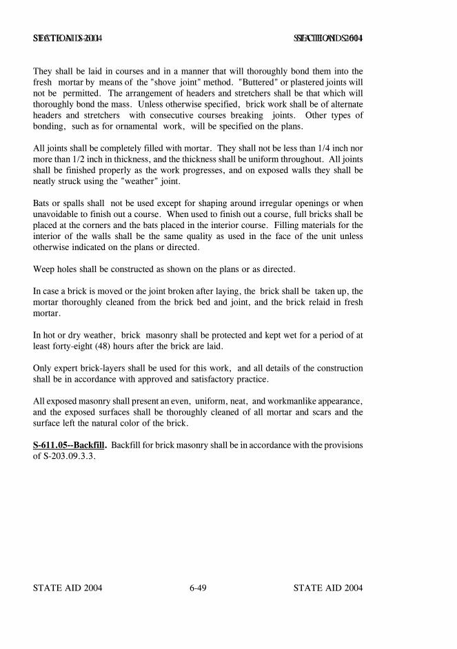
STATE AID 2004 STATE AID 2004
STATE AID 2004 STATE AID 20046-49
SECTION S-611 SECTION S-611
They shall be laid in courses and in a manner that will thoroughly bond them into thefresh mortar by means of the "shove joint" method. "Buttered" or plastered joints willnot be permitted. The arrangement of headers and stretchers shall be that which willthoroughly bond the mass. Unless otherwise specified, brick work shall be of alternateheaders and stretchers with consecutive courses breaking joints. Other types ofbonding, such as for ornamental work, will be specified on the plans.
All joints shall be completely filled with mortar. They shall not be less than 1/4 inch normore than 1/2 inch in thickness, and the thickness shall be uniform throughout. All jointsshall be finished properly as the work progresses, and on exposed walls they shall beneatly struck using the "weather" joint.
Bats or spalls shall not be used except for shaping around irregular openings or whenunavoidable to finish out a course. When used to finish out a course, full bricks shall beplaced at the corners and the bats placed in the interior course. Filling materials for theinterior of the walls shall be the same quality as used in the face of the unit unlessotherwise indicated on the plans or directed.
Weep holes shall be constructed as shown on the plans or as directed.
In case a brick is moved or the joint broken after laying, the brick shall be taken up, themortar thoroughly cleaned from the brick bed and joint, and the brick relaid in freshmortar.
In hot or dry weather, brick masonry shall be protected and kept wet for a period of atleast forty-eight (48) hours after the brick are laid.
Only expert brick-layers shall be used for this work, and all details of the constructionshall be in accordance with approved and satisfactory practice.
All exposed masonry shall present an even, uniform, neat, and workmanlike appearance,and the exposed surfaces shall be thoroughly cleaned of all mortar and scars and thesurface left the natural color of the brick.
S-611.05--Backfill. Backfill for brick masonry shall be in accordance with the provisionsof S-203.09.3.3.
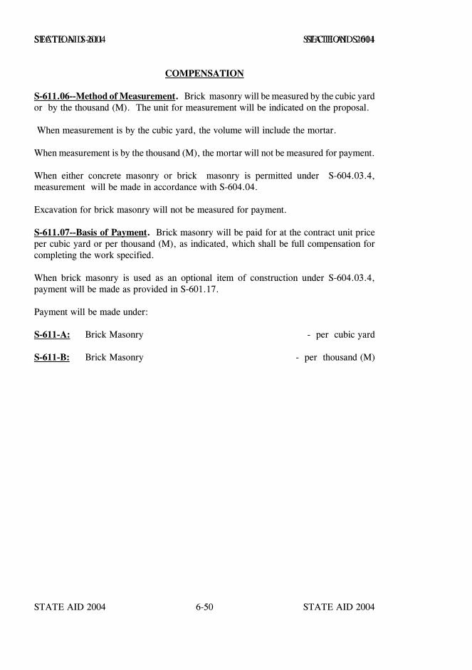
STATE AID 2004 STATE AID 2004
STATE AID 2004 STATE AID 20046-50
SECTION S-611 SECTION S-611
COMPENSATION
S-611.06--Method of Measurement. Brick masonry will be measured by the cubic yardor by the thousand (M). The unit for measurement will be indicated on the proposal.
When measurement is by the cubic yard, the volume will include the mortar.
When measurement is by the thousand (M), the mortar will not be measured for payment.
When either concrete masonry or brick masonry is permitted under S-604.03.4,measurement will be made in accordance with S-604.04.
Excavation for brick masonry will not be measured for payment.
S-611.07--Basis of Payment. Brick masonry will be paid for at the contract unit priceper cubic yard or per thousand (M), as indicated, which shall be full compensation forcompleting the work specified.
When brick masonry is used as an optional item of construction under S-604.03.4,payment will be made as provided in S-601.17.
Payment will be made under:
S-611-A: Brick Masonry - per cubic yard
S-611-B: Brick Masonry - per thousand (M)

STATE AID 2004 STATE AID 2004
STATE AID 2004 STATE AID 20046-51
SECTION S-612 - PRESSURE GROUTING
S-612.01--Description. This work consists of locating unstable concrete or otherpavement, voids, drilling of holes and the pumping of a slurry type grout mixture tostabilize and underseal the pavement voids. The grout mixture shall form a hard andinsoluble mass that will effectively fill the voids. Pavement that remains unstable afteran initial undersealing and stabilizing attempt shall be re-grouted as directed by theEngineer.
When a hot mix asphalt overlay is required, it shall be the Contractor's responsibility toschedule operations in such a manner that the first course of overlay will be placed at theearliest practicable time and no later than fourteen days after the pavement has beenstabilized.
When designated on the plans, this work shall also consist of drilling holes in the shoulderadjacent to cracks at the edge of the pavement and the pumping of a slurry type groutmixture to fill the cracks to the surface of the cement treated shoulder. Unless otherwisespecified, Type 1 grout shall be used. If in the Engineer's opinion, the type of groutbeing used proves to be unsatisfactory, the Contractor shall switch to a Type 5 grout atno change in contract price.
S-612.02--Materials. shall meet the follows requirements:
Materials used in the work shall meet the requirements specified in the following sectionsor subsections:
Portland Cement Types I or III ........................................................ S-701Calcium Chloride, Type I ........................................................ S-714.02*Fly Ash, Class C or F .............................................................. S-714.05Water ..................................................................S-714.01.1 and S-714.01.2Fine Aggregate .....................................................................S-703.18**Limestone Dust ..................................................................... S-612.02.1
* The Engineer may approve other commercially available accelerators which maybe substituted for calcium chloride.
** Fine aggregate shall meet the requirements of S-703.18 except that mortarmaking properties are not required.
S-612.02.1--Limestone Dust. The source of the material shall be approved by theEngineer and meet the following gradation requirements:
SIEVE PRECENT PASSINGNo. 30 ...................................................................... 95-100No. 200 ....................................................................... 20-100
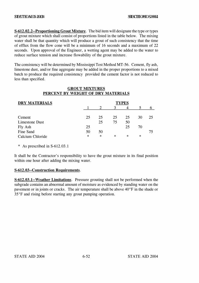
STATE AID 2004 STATE AID 2004
STATE AID 2004 STATE AID 20046-52
SECTION S-612 SECTION S-612
S-612.02.2--Proportioning Grout Mixture. The bid item will designate the type or typesof grout mixture which shall consist of proportions listed in the table below. The mixingwater shall be that quantity which will produce a grout of such consistency that the timeof efflux from the flow cone will be a minimum of 16 seconds and a maximum of 22seconds. Upon approval of the Engineer, a wetting agent may be added to the water toreduce surface tension and increase flowability of the grout mixture.
The consistency will be determined by Mississippi Test Method MT-56. Cement, fly ash,limestone dust, and/or fine aggregate may be added in the proper proportions to a mixedbatch to produce the required consistency provided the cement factor is not reduced toless than specified.
GROUT MIXTURESPERCENT BY WEIGHT OF DRY MATERIALS
DRY MATERIALS TYPES 1 2 3 4 5 6
Cement 25 25 25 25 30 25Limestone Dust 25 75 50Fly Ash 25 25 70Fine Sand 50 50 75Calcium Chloride * * * * *
* As prescribed in S-612.03.1
It shall be the Contractor's responsibility to have the grout mixture in its final positionwithin one hour after adding the mixing water.
S-612.03--Construction Requirements.
S-612.03.1--Weather Limitations. Pressure grouting shall not be performed when thesubgrade contains an abnormal amount of moisture as evidenced by standing water on thepavement or in joints or cracks. The air temperature shall be above 40°F in the shade or35°F and rising before starting any grout pumping operation.
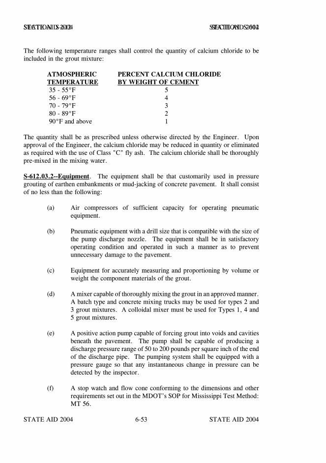
STATE AID 2004 STATE AID 2004
STATE AID 2004 STATE AID 20046-53
SECTION S-612 SECTION S-612
The following temperature ranges shall control the quantity of calcium chloride to beincluded in the grout mixture:
ATMOSPHERIC PERCENT CALCIUM CHLORIDETEMPERATURE BY WEIGHT OF CEMENT 35 - 55°F 5 56 - 69°F 4 70 - 79°F 3 80 - 89°F 2 90°F and above 1
The quantity shall be as prescribed unless otherwise directed by the Engineer. Uponapproval of the Engineer, the calcium chloride may be reduced in quantity or eliminatedas required with the use of Class "C" fly ash. The calcium chloride shall be thoroughlypre-mixed in the mixing water.
S-612.03.2--Equipment. The equipment shall be that customarily used in pressuregrouting of earthen embankments or mud-jacking of concrete pavement. It shall consistof no less than the following:
(a) Air compressors of sufficient capacity for operating pneumaticequipment.
(b) Pneumatic equipment with a drill size that is compatible with the size ofthe pump discharge nozzle. The equipment shall be in satisfactoryoperating condition and operated in such a manner as to preventunnecessary damage to the pavement.
(c) Equipment for accurately measuring and proportioning by volume orweight the component materials of the grout.
(d) A mixer capable of thoroughly mixing the grout in an approved manner.A batch type and concrete mixing trucks may be used for types 2 and3 grout mixtures. A colloidal mixer must be used for Types 1, 4 and5 grout mixtures.
(e) A positive action pump capable of forcing grout into voids and cavitiesbeneath the pavement. The pump shall be capable of producing adischarge pressure range of 50 to 200 pounds per square inch of the endof the discharge pipe. The pumping system shall be equipped with apressure gauge so that any instantaneous change in pressure can bedetected by the inspector.
(f) A stop watch and flow cone conforming to the dimensions and otherrequirements set out in the MDOT’s SOP for Mississippi Test Method:MT 56.
STATE AID 2004 STATE AID 2004
STATE AID 2004 STATE AID 20046-54
SECTION S-612 SECTION S-612
(g) Testing equipment shall consist of a tandem axle truck with dual wheelsand the rear axles shall be loaded to 50 kips evenly distributed. Themeasuring equipment shall consist of no less than two gages mountedon a measuring device that is capable of detecting movement of 0.001of an inch. A driver and sufficient personnel to assist in preliminarytesting, when required by the contract, and stability testing.
(h) Equipment to measure pavement lift shall consist of no less than fourgages mounted on a measuring device or devices that is capable ofdetecting movement on each side of a joint or crack and the adjoiningshoulder simultaneously. The equipment shall make such measurementsto 0.001 of an inch.
S-612.03.3--Testing.
S-612.03.3.1--General. When testing is required, it is intended to locate all pavementhaving a deflection exceeding 0.030 of an inch. Testing may begin as early as 4:00 A.M.and continue as long as the surface temperature of the pavement remains below 85°F.
S-612.03.3.2--Preliminary Testing by the Engineer. When the pavement has beentested and marked by the Engineer, preliminary testing will not be required by theContractor.
S-612.03.3.3--Preliminary Testing by the Contractor. When the contract includes aunit bid price for testing and it has not been performed by the Engineer, all of the projector designated areas shall be tested by the Contractor. Testing shall be performed asfollows:
One set of gages will be positioned on each side of a joint or crack near the pavementedge. The gages will be zeroed with no load on either side of the joint or crack. The testtruck will then be moved into position and stopped with the center of the nearest test axleabout one foot from the joint or crack and the outside test wheel about one foot from thepavement edge. The gages will be read and the test truck will then be moved across thejoint or crack to a similar position for a second reading of the gages. This operation willbe repeated for each joint or crack to be tested. The inspector will be responsible forreading the gages and subsequent recording. All locations with movement of more than0.030 of an inch will require pressure grouting.
When testing shoulders, gauge positioning and testing shall be the same as indicated abovefor roadway pavement. The Engineer may adjust the position of the gages to meet fieldconditions.
S-612.03.3.4--Stability Testing. After the designated areas have been pressure groutedin accordance with these specifications, they shall be retested in accordance withS-612.03.3.3 when the contract includes a unit bid price for testing.
STATE AID 2004 STATE AID 2004
STATE AID 2004 STATE AID 20046-55
SECTION S-612 SECTION S-612
Any undersealed pavement with movement of 0.030 of an inch or more shall bere-grouted and tested as directed.
Any pavement which continues to show movement in excess of that specified after twoproperly performed groutings may be accepted, or the slab may be removed and replacedas directed by the Engineer.
S-612.03.4--Drilling Holes. The hole pattern and pumping sequence shown on the plansshall be used, except when modified to use drilling holes made from previousundersealing work. The Contractor may alter the hole pattern with the Engineer'sapproval. However, only the actual number of holes drilled will be measured forpayment.
The holes shall be of a size and shape that best provide a positive seal for the pumpingnozzle. The holes shall be drilled to a depth of approximately eight inches below thebottom of the concrete for the initial undersealing unless the Engineer approves analternate depth. The number, depth and location of holes for undersealing after the initialoperation shall be approved by the Engineer.
When pressure grouting cracks located in the shoulders at the edge of the pavement, theholes in the shoulders shall be located as shown on the plans or as directed by theEngineer. These holes are to be drilled below the treated base.
S-612.03.5--Cleaning Holes. Prior to pumping the grout, compressed air shall be usedto remove debris and to help provide a passage for the grout.
S-612.03.6--Pumping the Grout. The nozzle of the discharge hose shall be secured inthe hole in a manner that provides a seal adequate to maintain the grout pressureunderneath the slab. The nozzle end shall not extend below the bottom of the concrete.Pumping will continue until a clear flow of grout protrudes from an adjacent hole, jointor crack, or until the pavement begins to lift. This procedure will be repeated in otherholes until all voids are supposedly filled. Plugging of holes during grouting operationswill not be permitted.
Additional evidence that grouting should cease is a rapid rise of the pavement, or a riseof the adjacent shoulder. A minimum lifting of the pavement will generally be requiredto move grout into the cavities and voids, however, the lifting shall not exceed 0.050 ofan inch. Movement of the pavement and adjacent shoulder will be monitored by theContractor with equipment as required by S-612.03.2(h). Care shall be taken not to crackthe pavement by differential lifting. During pumping, very close attention shall be givento the lift measuring device to prevent excessive pumping pressures.
STATE AID 2004 STATE AID 2004
STATE AID 2004 STATE AID 20046-56
SECTION S-612 SECTION S-612
Moderate to major pavement cracks or pavement broken during the pumping operationdue to the Contractor's negligence will be repaired or removed and replaced at theContractor's expense.
S-612.03.7--Clean Up and Opening to Traffic. Deposits of mud and/or grout on thepavement or shoulders shall be removed and the surface cleaned before traffic is permittedon the section. Other debris, bags, spillage, etc., shall be removed from the right-of-wayeach day.
Traffic shall not use the undersealed pavement for at least three hours after grouting.Grouting operations shall cease at least three hours before sundown or earlier as necessaryto permit the grout to harden at least three hours.
S-612.03.8--Permanently Sealing Holes. When pavement is not to be overlaid all groutshall be removed from the holes to the bottom surface of the concrete pavement and filledwith a stiff sand-cement mixture or an approved quick setting patching material. Filledholes that ravel out or become damaged shall be repaired. All holes from previousundersealing work that were used by the Contractor shall also be similarly repaired at nocost to the Project.
S-612.03.9--Stability Tests. The test shall not be conducted until the undersealedpavement has been open to traffic for at least twelve hours. These tests shall be conductedin accordance with S-612.03.3.4. Based upon these test results the pavement will beaccepted or designated for further undersealing or replaced as directed by the Engineer.
S-612.04--Method of Measurement. Holes drilled at locations and to the depths shownon the plans or directed by the Engineer will be measured per each. Additional holesrequired for subsequent undersealing operations will be measured per each.
Portland Cement incorporated into the grout mixture will be measured by the pound.
Calcium chloride incorporated into the completed work in accordance with the provisionsof the contract will be measured by the pound.
When required, preliminary testing in accordance with S-612.03.3.3 will be measured bythe mile, linear horizontal measure, for each lane of roadway.
Stability testing at each joint or crack in accordance with S-612.03.3.4 will be measuredper each lane joint or each lane crack, up to a maximum of three tests.
STATE AID 2004 STATE AID 2004
STATE AID 2004 STATE AID 20046-57
SECTION S-612 SECTION S-612
S-612.05--Basis of Payment. Holes will be paid for at the contract unit price per each,which price shall be full compensation for drilling and sealing the hole.
The portland cement and calcium chloride incorporated into the grout mixture will be paidfor at the contract unit price per pound, which price shall be full compensation forfurnishing materials to be incorporated into the specified type of grout mixture, for allhauling, mixing, pumping and clean-up required to stabilize the pavement.
Preliminary testing will be paid for at the contract unit price per mile, which price shallbe full compensation for furnishing all testing equipment, the load test truck and necessarypersonnel to assist in the testing.
Stability testing will be paid for at the contract unit price per each test and shall be fullcompensation for furnishing all testing equipment, the load test truck and necessarypersonnel to assist in the testing.
Payment will be made under:
S-612-A: Holes * - per each
S-612-B: Portland Cement Pressure Grout Slurry, Type _____ - per pound
S-612-C: Calcium Chloride - per pound
S-612-D: Preliminary Testing - per mile
S-612-E: Stability Testing, Lane Joint - per each
S-612-F: Stability Testing, Lane Crack - per each
* Indicate “In Shoulders” when holes are required in shoulders
STATE AID 2004 STATE AID 2004
STATE AID 2004 STATE AID 20046-58
SECTION S-613 - ADJUSTMENT OF CASTINGS, GRATINGS ANDUTILITY APPURTENANCES
S-613.01--Description. This work shall consist of furnishing all materials and adjustingexisting catch basins, inlets, manholes and other designated structures in accordance withthese specifications and in reasonably close conformity with the lines, grades anddimensions shown on the plans or as established.
MATERIALS
S-613.02--Material Requirements. New materials used in this construction, unlessotherwise stipulated, shall conform to the requirements set out in S-604.
CONSTRUCTION REQUIREMENTS
S-613.03--General. Construction requirements shall be, insofar as applicable, asdescribed in S-604. Castings, gratings, frames, covers, and other metal units shall becleaned before resetting.
Where a casting, grating, or utility appurtenance is to be lowered, the masonry shall beremoved to sufficient depth so that a set of proper dimensions may be reconstructed toreceive the castings, grating or utility appurtenance at the new grade. Where the casting,grating or utility appurtenance is to be raised less than one foot, a new ring of masonrymay be added without disturbing the old masonry. Where the distance to be raisedexceeds one foot, the old masonry shall be removed to sufficient depth, as directed, topermit a neat and workmanlike extension to the new grade.
The Contractor shall replace at his own expense all units or parts indicated to be salvagedand reused which are damaged as a result of his operation.
S-613.04--Cleaning Up. Upon completion of the adjustment, all surplus material shallbe removed, and the structure and site of the work shall be left in a neat and cleancondition. The entire structure shall be thoroughly cleaned of accumulations of silt,debris, or foreign matter of any kind and shall be kept clean until the final inspection.
S-613.05--Method of Measurement. Acceptably adjusted castings, gratings, and utilityappurtenances for which pay items are included in the contract will be measured on alump sum basis or by the number of units, as specified.
STATE AID 2004 STATE AID 2004
STATE AID 2004 STATE AID 20046-59
SECTION S-613 SECTION S-613
CONSTRUCTION REQUIREMENTS
S-613.06--Basis of Payment. Adjustment of castings, gratings, and utility appurtenancesfor which pay items are included in the contract will be paid for at the contract lump sumprice or at the contract unit price per each, as indicated, which shall be full compensationfor completing the work specified.
Payment will be made under:
S-613-A: Adjustment of Castings, Gratings and Utility Appurtenances - per lump sum
S-613-B: Adjustment of Castings - per unit
S-613-C: Adjustment of Gratings - per unit
S-613-D: Adjustment of - per lump sum (Description)
S-613-E: Adjustment of - per unit (Description)
Sections S-614 and S-615 - Blank.
STATE AID 2004 STATE AID 2004
STATE AID 2004 STATE AID 20046-60
SECTION S-616 - TRAFFIC ISLAND PAVEMENT
S-616.01--Description. This work shall consist of furnishing all materials andconstructing paved islands on a prepared grade in accordance with these specifications,at the locations specified and in reasonably close conformity with the lines, grades, andtypical sections shown on the plans or as established. When so indicated on the plans, thiswork shall also consist of markings by painting the surface, or portions thereof, of theisland as specified.
S-616.02--Material Requirements. The materials used in this construction, in additionto conforming with the requirements of S-700 for materials specified and used, unlessotherwise stipulated, shall conform to the following:
S-616.02.1--Concrete. The materials used in the manufacture of concrete shall conformto the requirements for the class of concrete specified as set out in S-804, as shown onthe plans and in the proposal, or as otherwise indicated in the contract. Unless otherwisespecified, Class "C" concrete shall be used.
S-616.02.2--Joint Filler. Joint filler shall be of the type specified on the plans and shallconform to the requirements as set forth in S-707 for the particular type specified. Unlessotherwise specified, the filler shall be 1/2 inch premolded filler in accordance withS-707.02.2.
S-616.02.3--Hot Plant Mix Pavement. Hot Plant Mix Pavement shall be in accordancewith the applicable materials and construction requirements of S-401 and S-403.
CONSTRUCTION REQUIREMENTS
S-616.03--Equipment. The equipment shall conform to the requirements of S-401 andS-804, as applicable, with the exception of approved modified placement, shaping,compacting and finishing equipment will be permitted. All small tools, such as edgers,floats, tamps, etc., shall be approved tools of such quality and quantity as to assure theiradequacy in the performance of acceptable work. Approved equipment necessary andrequired, shall be on the project in good working condition before construction will bepermitted to start.
S-616.04--Preparation of Grade. Grade preparation shall be performed in accordancewith the applicable provisions and requirements of S-205. After shaping as required, theentire area shall be treated with a soil sterilant as follows:
(a) Soil sterilant material shall be applied at the maximum rate recommended onthe manufacturer's label for perennial weed control. Any granular orpelletized type soil sterilant that is approved by the Engineer may be used.The approved material shall be uniformly spread over the entire areaimmediately prior to placing the pavement.
STATE AID 2004 STATE AID 2004
STATE AID 2004 STATE AID 20046-61
SECTION S-616 SECTION S-616
(b) The chemical compounds shall be delivered to the job in unbrokencontainers with the manufacturer's label thereon.
(c) The Contractor shall be responsible for performing all precautions as shownon the label of the containers and shall be liable for any injury or damagecaused from handling or using the material until acceptance of the project.
(d) Furnishing and placement of soil sterilant shall be absorbed in the cost of theother bid items.
S-616.05--Forms. Forms will not ordinarily be required, however, as specified ornecessary, forms and forming shall be in accordance with the requirements of S-608.05.
S-616.06--Manufacturing and Placing Concrete. The concrete used in the constructionof island pavement shall be manufactured, proportioned and placed in accordance withthe requirements of S-804 - Concrete Bridges and Structures, with the exception ofapproved modified methods of placement, shaping and compacting will be permitted.Concrete surfaces shall be given a Class 6 float finish.
Immediately after mixing, the concrete shall be deposited in a single layer on the moistgrade to such depth that, after finishing, it shall be of the full thickness required. Theedges, side, etc., shall be thoroughly spaded, and the surfaces tamped sufficiently tocompact the concrete and bring mortar, for finishing, to the surface.
The surface of the finished concrete shall conform closely to the typical section indicatedon the plans and shall be without any irregularities which would not permit completesurface drainage, including drainage over the adjacent curb as indicated.
The edges of the concrete at expansion joints shall be edged with an edger having a radiusof 1/2 inch.
S-616.07--Blank.
S-616.08--Expansion Joints. Unless otherwise shown on the plans, expansion joints shallbe formed of premolded joint filler of the specified thickness, and shall be placed at thelocations indicated on the plans. All joint fillers shall be cut to full cross-section and shallextend to the full depth, width and length of the construction. Any expansion jointmaterial extruding after the concrete is finished, shall be trimmed as directed.
In the event the locations are not shown on the plans, specified joints shall be placedbetween all edges of the island pavement and the surrounding curb or pavement.

STATE AID 2004 STATE AID 2004
STATE AID 2004 STATE AID 20046-62
SECTION S-616 SECTION S-616
S-616.09--Protection and Curing. After the concrete is completed, it shall be protectedand cured in accordance with the requirements of S-804.03.17 or other approved method.
Conditions governing the placement of concrete and the requirements for the placement,protection and curing of concrete during cold or hot weather shall conform to thelimitations, conditions and requirements of S-804.03.16.1 or S-804.03.16.2, asapplicable.
S-616.10--Manufacturing and Placing Asphalt Pavement. The Hot Mix AsphaltPavement used in construction of island pavement shall be manufactured and placed inaccordance with the requirements of S-401 and S-403, except that approved modifiedmethods of placement, shaping and compacting will be permitted. The pavement shallconsist of the layers and types as shown on the plans.
The surface of the finished Hot Mix Asphalt Pavement shall conform closely to thetypical section indicated on the plans and shall be without any irregularity which wouldnot permit complete surface drainage, including drainage over the adjacent curb asindicated.
S-616.11--Cleaning Up. All surplus material shall be disposed of as directed, and thecompleted work and the site shall be left in a neat and presentable condition.
S-616.12--Markings. When shown on the plans, pavement markings on island pavementshall be constructed as detailed, or as directed by the Engineer, and shall conform to allprovisions and requirements of the applicable section(s), including measurement andpayment, for the particular markings included in the contract.
S-616.13--Method of Measurement. The area of the completed and accepted islandpavement will be measured in square yards of the actual area so paved.
Excavation will not be measured for payment, it being understood that the cost thereofis included in the other items of work.
Pavement markings, if required, will be measured as provided in the applicablesection(s) for such items.
STATE AID 2004 STATE AID 2004
STATE AID 2004 STATE AID 20046-63
SECTION S-616 SECTION S-616
S-616.14--Basis of Payment. This work, measured as provided in S-616.13, will bepaid for at the contract unit price bid per square yard, which price shall be fullcompensation for all incidental excavation and disposal of surplus material; for allmaterials; for all construction as specified herein or otherwise provided in the contract forisland pavement; for all forms and forming if necessary and for all equipment, tools,labor and incidentals necessary to complete the work.
Payment will be made under:
S-616-A: Concrete Island Pavement - per square yard
S-616-B: Hot Mix Asphalt Island Pavement - per square yard
STATE AID 2004 STATE AID 2004
STATE AID 2004 STATE AID 20046-64
SECTION S-617 - RIGHT-OF-WAY MARKERS
S-617.01--Description. This work shall consist of furnishing and placing concretemarkers in accordance with the plans and these specifications or as directed. The workalso shall include the removal of right-of-way markers from their original locations andresetting at new locations as specified or established.
MATERIALS
S-617.02--Material Requirements. The materials used in this construction shallconform to the requirements of S-706.04.
CONSTRUCTION REQUIREMENTS
S-617.03--Construction Requirements. Markers shall be cast in accordance with thedetails shown on the plans, the requirements of S-706.04, and the requirements of thissection.
Reinforcement shall conform to the details shown on the plans and the requirements ofS-602.
All letters and other markings shall be as shown on the plans and shall be neatlyimprinted in the markers. Where required on the plans, the markings shall be paintedin a workmanlike manner with the type of paint specified.
The markers shall be set to the depth and in the position designated on the plans andestablished by the Engineer. They shall be set to within 1/4 inch of the lines indicated orestablished, 1/2 inch of the depth or elevation indicated or directed, and in a verticalposition within a tolerance of 1/8 inch per foot. Backfilling shall be made with suitablematerial thoroughly tamped in six- inch layers. All surplus material shall be disposedof as directed and the site shall be left in a neat and presentable condition.
S-617.04--Removal and Resetting. Markers which are specified to be removed and resetshall be carefully removed and reset at the location indicated and established in accordancewith the provisions and requirements of S-617.03.
The Contractor shall replace without additional compensation all markers broken ordamaged due to his carelessness or negligence during the removal and resetting operation.
STATE AID 2004 STATE AID 2004
STATE AID 2004 STATE AID 20046-65
SECTION S-617 SECTION S-617
COMPENSATION
S-617.05--Method of Measurement. New and removed and reset right-of-way markerswill be measured per each.
S-617.06--Basis of Payment. Right-of-way markers complete in place will be paid forat the contract unit price per each, which shall be full compensation for completing thework specified.
Payment will be made under:
S-617-A: Right-of-Way Markers ( ) - per each (Type)
S-617-B: Right-of-Way Markers Removed and Reset - per each
STATE AID 2004 STATE AID 2004
STATE AID 2004 STATE AID 20046-66
SECTION S-618 - MAINTENANCE OF TRAFFIC ANDTRAFFIC CONTROL PLAN
S-618.01--Description.
S-618.01.1--General. This work shall consist of maintaining two-way local traffic at alltimes, except as provided herein or in other contract documents. It shall consist ofremoving temporary structures, constructing and maintaining in good condition approachroadways and other facilities required for the maintenance of traffic and furnishingtemporary materials therefor, unless otherwise indicated in the contract.
This work shall include furnishing, erecting, maintaining in good condition, and removingall required construction signs, barricades, and temporary traffic stripe.
S-618.01.2--Traffic Control Plan. This work shall also consist of complying with thecontract requirements of the Temporary Traffic Control Plan. The purpose of theTemporary Traffic Control Plan is to maintain through and local traffic safely throughconstruction zones. In addition to this section, the Plan includes: S-104.04, S-105.15,S-107.07, and S-107.10; special provisions modifying this section and supplementsthereto; individual plan sheets applicable to the plan; and Part VI of the Manual onUniform Traffic Control Devices (MUTCD), latest edition. These parts of the Plan arelisted for the bidders' information and do not change provisions of the contract, listed orunlisted, unless so specifically stated.
Where the plans call for guardrail to be replaced or removed and reset, all material shallbe on hand at the time of removal and the resetting will be accomplished as per subsectionS-606.05.1.
The Contractor's Traffic Safety Officer's responsibility shall be maintenance of theeffectiveness of the Temporary Traffic Control Plan. The Contractor's Traffic SafetyOfficer's duties shall include the following:
1. Understand the requirements of the MUTCD and contract provisions.
2. Be responsible for assuring compliance of the Contractor's maintenance andprotection of traffic relative to the requirements of the contract provisions.
3. Be responsible for maintaining current documentation of deficiencies withrespect to the Contractor's maintenance and protection of traffic operations.
4. Be responsible for maintaining documentation on how and when thedeficiencies were corrected.
STATE AID 2004 STATE AID 2004
STATE AID 2004 STATE AID 20046-67
SECTION S-618 SECTION S-618
5. Hold Contractor's traffic safety meetings.
6. Be responsible for assuring that all deficiencies are corrected.
7. Be responsible for coordinating maintenance of traffic operations with theEngineer.
8. Be responsible for reviewing Contractor's equipment location storage andoperation relative to traffic safety and operation as required by the contractprovisions.
9. Be responsible for reviewing Contractor's material location storage andhandling of materials relative to traffic safety and operations.
10. Be responsible for maintaining current documentation of deficiencies andcorresponding corrections relative to equipment operation, equipmentstorage, and material handling and storage pertaining to traffic safety andoperations.
The Contractor shall also provide a suitable traffic vehicle, adequately marked andequipped, for the use of the Traffic Safety Officer. The Engineer shall be furnished withthe telephone numbers where the Contractor's Traffic Safety Officer and a substitute,authorized to act in his absence, may be reached at all times when not on the project.This in no way modifies the requirements of S-105.05 regarding the assignment andavailability of the superintendent.
Within three weeks time the Contractor shall provide the Engineer with a copy of eachaccident report for those accidents occurring within the limits of the project. In the eventno accident report is available, the Contractor and the Engineer shall jointly attempt todescribe the accident from sources or information that may be available. The Engineer,or other appropriate personnel as required, will analyze these reports to determine ifcorrective action is needed.
In the event corrective action is indicated, the Contractor shall proceed immediately withsame.
The Engineer will designate a responsible person at the project level to monitor theContractor's compliance with the plan.
STATE AID 2004 STATE AID 2004
STATE AID 2004 STATE AID 20046-68
SECTION S-618 SECTION S-618
MATERIALS
S-618.02--Material Requirements. Unless otherwise specified, the Contractor shallprovide all materials for the construction and maintenance of detours required for themaintenance of traffic, except the Engineer may permit the Contractor to use excavationfrom the roadbed, or other designated sources, that is available at the time of constructionof diversions without detriment to the work and provided the excavation is ultimatelyplaced in its final position in the roadbed in an uncontaminated condition. No additionalcompensation will be made to the Contractor for the extra handling of the material.
Unless otherwise specified, the applicable material requirements set out in the S-700 seriesof sections or in other contract documents shall apply to all materials used in temporarytraffic facilities. The Contractor shall select and use materials that with adequatemaintenance or replacement will provide a satisfactory facility for the entire period thetemporary facility is required.
CONSTRUCTION REQUIREMENTS
S-618.03--Construction Details.
S-618.03.1--General. All diversions shall be constructed and maintained in such amanner that they will adequately carry the required traffic.
Requirements for temporary traffic facilities shown on the plans, or set forth in thesespecifications, shall be understood to be the minimum requirements anticipated. Actualtraffic conditions may require work or devices in addition to those shown on the plans.
Traffic lanes shall be kept free of dust, and when deemed necessary they shall besprinkled with water, or some other dust palliative shall be applied.
Unless otherwise specified, temporary structures and roads shall be sufficiently strong tosafely carry the load permitted on the road under construction. Structures shall beprovided with suitable curbs, rails, or other devices as required for the protection oftraffic. Unless otherwise specified, walkways when required for pedestrians shall havea clear width of at least four feet and shall be protected from vehicular traffic in themanner specified or directed.
Unless otherwise specified, the Contractor shall remove all temporary diversions,satisfactorily dispose of all surplus materials, grade, finish, and dress the disturbed areasto the required section, and complete all work incidental thereto prior to final acceptance.
STATE AID 2004 STATE AID 2004
STATE AID 2004 STATE AID 20046-69
SECTION S-618 SECTION S-618
S-618.03.2--Barricades, Signs, and Flaggers. The Contractor shall construct, erect, andmaintain in good order all barricades and danger and warning signs specified or ordered.
Flaggers shall be stationed at such points as may be deemed necessary. Movableconstruction signs shall be moved from sections as their use become inapplicable.
Such signs and all other signs and devices of a temporary nature shall be in accordancewith the plans, and the MUTCD, as applicable.
S-618.04--Widening, Overlays, and Seal Coats. On widening or widening andoverlaying projects, the Contractor shall limit the base widening, pavement removal,undercutting, and patching operations to the lengths that are deemed to be consistent withbackfilling and traffic handling requirements.
Pavement edge excavated for widening shall be protected with drums, cones, verticalpanels or barricades until the trench is filled and compacted.
On the traffic lane adjacent to the lane being paved, opposing traffic may be alternatelyrouted over the single lane in such a manner as to provide safe movement of the trafficwith minimum delay. In such case, flaggers will be required and, when deemednecessary, an approved pilot vehicle with sign meeting the requirements of the plans andthe current edition of the Manual on Uniform Traffic Control Devices (MUTCD), shallbe provided and operated to control the speed and sequence of movement of the traffic.
A pavement edge that traffic is expected to cross in changing lanes should have anelevation difference of no greater than 1 1/2 inches There should be adequate signs towarn the traveling public of lane drop-off.
All failed areas that have been removed and all trenches shall be filled and compacted tothe elevation of the existing pavement before work is discontinued for the day. Inemergencies, the Engineer may permit the use of approved temporary materials forbackfill, provided the temporary materials will be adequate to facilitate normal safemovement of traffic. Separate measurement for payment will not be made for thefurnishing, placing, maintaining, removing, and disposing of such temporary materials.
STATE AID 2004 STATE AID 2004
STATE AID 2004 STATE AID 20046-70
SECTION S-618 SECTION S-618
Except under the following conditions, no portion of the roadway which is intended to beused for maintenance of traffic shall be blocked after work hours. In exceptional caseswhen all efforts have been made to restore the surface of the roadway and because ofequipment failure or other uncontrollable causes complete restoration is not possiblebefore work must be discontinued for that day, the Contractor shall provide adequatewarning signals, barricades, flares, other appropriate devices, and flaggers, appropriatelyplaced or stationed for the protection of the public. The Engineer may also require theuse of a pilot vehicle as provided herein.
S-618.05--Contractor's Responsibility. The Contractor shall be responsible forprotection against loss or damage from any cause to all temporary structures (includingapproaches), and shall maintain them in a satisfactory condition until their use is no longerrequired. If a temporary structure, or approaches, is damaged due to high water or otherreasons, it shall be replaced by the Contractor without extra compensation, except that fortemporary structure and approaches constructed of materials and to the grades andsections indicated on the plans and in accordance with the applicable constructionrequirements of the contract and adequately maintained, consideration will be given underthe conditions and provisions of S-107.17.
The Contractor shall maintain the surface of the existing facility and connections theretoon which he is required to maintain traffic. Such maintenance shall be in accordance withthe provisions of S-104.04 and S-105.14 and other applicable requirements and shall besubject to the provisions of S-105.15. All costs for such maintenance and surface repairsshall be included in the contract price bid for Maintenance of Traffic. Repair of structuralfailures in the pavement foundation, or a structure beneath the surface not resulting fromthe Contractor's failure to comply with the requirements or limitations of the contract, orfrom his operations, will be the responsibility of the County. The Board and State AidEngineer may, however, at their discretion require the Contractor to make repairs andwill pay for them at the contract unit prices for the items and quantities of work involvedor as Extra Work.
COMPENSATION
S-618.06--Method of Measurement. This work will be measured as a unit (lumpsum) quantity consisting of continuous maintenance and protective services. Thepercentages of the contract lump sum price allowed on the monthly estimate will bedetermined by the percentage of the combined total monetary value of all bid itemsearned during the current (same) estimate period.
In the event the Engineer determines that actual field and traffic conditions requirefixed-in-place signs in addition to those shown on the plans, they shall be furnished,erected, and maintained, and measurement of these signs will be made by the squarefoot.
STATE AID 2004 STATE AID 2004
STATE AID 2004 STATE AID 20046-71
SECTION S-618 SECTION S-618
S-618.07--Basis of Payment. Maintenance of traffic will be paid for at the contract lumpsum price which will also include compensation for complying with the requirements ofthe Traffic Control Plan.
For contracts not containing pay items for individual traffic control devices, additionalconstruction signs ordered by the Engineer will be paid for at the fixed contract unit priceindicated in the proposal.
These prices shall be full compensation for completing the work specified.
Payment will be made under:
S-618-A: Maintenance of Traffic - per lump sum
S-618-B: Additional Construction Signs - per square foot
STATE AID 2004 STATE AID 2004
STATE AID 2004 STATE AID 20046-72
SECTION S-619 - HOT SPRAY PAINT TRAFFIC MARKINGS
S-619.01--Description. This work shall consist of furnishing materials and applyingreflectorized 40 mil thick hot spray paint pavement markings in reasonably closeconformity with these specifications and the details shown on the plans or established.
MATERIALS
S-619.02--Materials. Paint shall be the color specified and shall meet the applicablerequirements of S-710. The materials shall be a mixture of resins and other materialsmeeting EPA requirements for essentially non-volatile paint compound for trafficmarkings. Glass beads shall meet the requirements of S-710.03.5 and S-710.03.6.
Temporary raised pavement markers shall meet the requirements of this section andS-720.02.
CONSTRUCTION REQUIREMENTS
S-619.03--Equipment. The equipment used to install hot applied paint material shallprovide continuous uniform heating to temperatures exceeding 400oF, mixing andagitation of the material. Conveying parts of the equipment between the main materialreservoir and the line dispensing device shall prevent accumulation and clogging. Allparts of the equipment which come in contact with the material shall be constructed foreasy accessibility and exposure for cleaning and maintenance. The equipment shalloperate so that all mixing and conveying parts including the line dispensing device,maintains the material at the plastic temperature.
Glass beads applied to the surface of the completed marking shall be applied by anautomatic bead dispenser attached to the marking machine so that the beads aredispensed closely behind the installed marking. The glass bead dispenser shall beequipped with an automatic cut-off control synchronized with the cut-off of the paintmaterial.
All painting equipment and operations shall be under the control of an experiencedtechnician thoroughly familiar with the equipment, materials, and marking layouts.
S-619.04--Preparation of Surface. All areas to be painted shall be thoroughly cleaned.Cleaning may be done by hand brooms, rotary brooms, air blast, scrapers, or whatevercombination of equipment is necessary to clean the pavement thoroughly without damageto the surface. Before edge striping, particular care shall be taken to remove allvegetation, loose soil, and the like from the area to be painted. Should other methods fail,the surface shall be wetted with a water jet and scrubbed as necessary to dislodge allforeign material.
STATE AID 2004 STATE AID 2004
STATE AID 2004 STATE AID 20046-73
SECTION S-619 SECTION S-619
After washing, the surface shall be allowed to dry thoroughly, and all films of dried mudapparent after surface drying shall be removed before application of paint. Painting shallfollow as closely as practicable after the surface has been cleaned and dried, but no paintshall be applied until the surface has been inspected and permission given to proceed.The cost for preparing the surface shall be included in the unit prices bid for the markingitems.
The paint material shall be readily renewable by placing an overlay of new materialdirectly over old markings of the same material. Such new material shall bond itself tothe old markings in such a manner that no splitting or separation takes place. Thecontractor shall remove all existing material that might cause premature failure of thenew material.
Upon request, the Engineer will establish control points for markings, by type and color,at necessary intervals not to exceed six hundred (600) feet. The Contractor shall preserveand apply markings in conformity with these control points, if established.
S-619.05--Application. The paint material shall be installed in a molten state by the spraymethod at a minimum temperature of 350oF and a maximum temperature of 425oF.Scorching or discoloration of material shall be cause for rejection by the Engineer. Themachinery shall be constructed so that all mixing and conveying parts, up to andincluding the spray gun maintain the material in the molten state.
Paint pavement marking materials shall not be applied by the spray method when air andpavement surface temperatures are below 40oF or when the surface of the pavementcontains any evidence of moisture.
The paint material shall be applied at a thickness of not less than 40 mils, but in no caseshall it exceed a thickness of 50 mils.
The Contractor shall place the paint markings with adequate drop-on glass beads inaccordance with requirements, uniformly applied to assure adequate nighttime reflectivity.It shall be the Contractor's responsibility to use a compatible combination of paint materialand beads to preclude the surface beads from sinking deeply into the paint.
The length and width of lines shall be within a tolerance of plus or minus three inches andplus or minus 1/8 inch, respectively. For skip markings, the length of intervals shallnot exceed the line length tolerance. Markings applied at less than minimum materialrates, deviating from true alignment by more than one inch in fifty (50) feet, exceedingstipulated length and width tolerances, and showing light spots, faulty distribution ofbeads, smears, tracking due to traffic or other deficiencies or irregularities shall beremoved and replaced. Removal methods shall be in accordance with S-619.08.
STATE AID 2004 STATE AID 2004
STATE AID 2004 STATE AID 20046-74
SECTION S-619 SECTION S-619
S-619.06--Detail Traffic Stripe. Detail traffic stripe shall be those short stripes,exclusive of lane and edge striping, at exit and entrance ramps, turnouts, turn bays, andother locations indicated on the plans. When shown on the plans or directed by theEngineer, detail stripe of the color, width, and length shall be placed in accordance withthe provisions and requirements of this section.
S-619.07--Legend. Legend shall be applied by the use of templates cut to thedimensions shown on the plans, or by other methods approved by the Engineer whichwill provide a clean cut, uniform, and workmanlike appearance. All other requirementsfor legend shall be in accordance with the applicable materials and constructionrequirements of this section.
Legend which fails to have a uniform, satisfactory appearance either by day or by nightshall be corrected by the Contractor or removed and replaced without additional cost tothe Project.
S-619.08--Temporary Traffic Striping. When shown on the plans or directed by theEngineer, temporary stripe of the color(s) specified shall be placed in accordance with theprovisions and requirements of this section. The length of each stripe of skip stripingshall be at least four (4) feet with stripes of the same length and with skips of uniformlength of forty (40) feet center to center of stripes.
After it has served its purpose and when so ordered by the Engineer, temporary stripeshall be removed by carefully controlled blast cleaning, approved grinding equipment, orother approved methods in such a manner that the surface to which the stripe was appliedwill not be unnecessarily damaged.
Unless otherwise specified, pressure sensitive, reflective adhesive tape meeting therequirements of S-720.05 for Type 2 may be used in lieu of temporary painted stripe.The Contractor shall replace portions of tape as necessary, and shall remove all tem-porary markings when specified or directed.
When noted on the plans temporary raised pavement markers shall be installed as permanufacturers recommendation or as directed by the Engineer. The temporary raisedmarkers shall be flexible reflective tabs placed at forty (40) foot intervals on the centerlineof the roadway. The markers shall be installed in a manner that reflective faces of themarker are perpendicular to a line parallel to roadway centerline.
If, in the opinion of the Engineer, the temporary raised markers require removing afterpermanent striping has been accomplished, they shall be removed in such a manner thatthe pavement surface will not be unnecessarily damaged.
STATE AID 2004 STATE AID 2004
STATE AID 2004 STATE AID 20046-75
SECTION S-619 SECTION S-619
S-619.09--Acceptance:
(a) Paint - The manufacturer shall furnish the Engineer three (3) copies of certifiedtest report(s) showing results of all required test(s) and certification(s) that thematerial meets the specifications. Prior to beginning striping a test section shallbe performed on a prepared surface to determine if the specified thickness isobtained. During the striping operation the Engineer shall measure and recordthe thickness of stripe at random selected areas and record to insure adequate rateof application.
(b) Glass Beads - The manufacturer shall furnish the Engineer three (3) copies ofcertified test report(s) showing results of all required test(s) and certification(s)that the material meets the specifications. The Engineer shall documentacceptance as per S.O.P. No. SA-II-3-5.
COMPENSATION
S-619.10--Method of Measurement. Traffic Stripe will be measured horizontally by themile or by the linear foot. The length used to measure centerline and edge stripes will bethe horizontal length computed along the stationed control line. In the case of skip lines,the measurements will include skip intervals as well as painted sections.
Detail traffic stripe will be measured by the linear foot from end-to-end of individualstripes. Measurement will be made along the surface of each stripe and will include skipintervals where specified. A normal stripe is 4 to 6 inches wide, as indicated in the plans.Wide stripes will be converted to equivalent lengths of the normal stripes.
Legend will be measured by the square foot. Pay areas of individual components oflegend will usually be shown on the plans.
When shown as a pay item, temporary traffic stripe completed and removed in accordancewith the requirements of the contract will be measured by the linear foot from end-to-endof individual stripes. Measurement will be made along the surface of each stripe and willinclude skip intervals where skips are specified.
S-619.11--Basis of Payment. Traffic stripe will be paid for at the contract unit price permile or by the linear foot as indicated in the proposal.
Detail traffic stripe will be paid for at the contract unit price per linear foot.
Legend will be paid for at the contract unit price per square foot.
Temporary traffic stripe will be paid for at the contract unit price per linear foot.
STATE AID 2004 STATE AID 2004
STATE AID 2004 STATE AID 20046-76
SECTION S-619 SECTION S-619
The prices thus paid shall be full compensation for completing the work specified.
When temporary raised markers are shown on the plans there shall be no separate payitem for this portion of work. The contractor shall include the material and labor forinstallation of these markers in the Maintenance of Traffic Pay Item S-618-A.
Payment will be made under:
S-619-A: “ Wide Traffic Stripe (Skip White) - per mile
S-619-AB: “ Wide Traffic Stripe (Skip White) (Type III Drop On Glass Beads) - per mile
S-619-B: “ Wide Traffic Stripe (Skip Yellow) - per mile
S-619-BB: “ Wide Traffic Stripe (Skip Yellow) (Type III Drop On Glass Beads) - per mile
S-619-C: “ Wide Traffic Stripe (Continuous White) - per linear foot
S-619-CB: “ Wide Traffic Stripe (Continuous White) (Type III Drop On Glass Beads) - per linear foot
S-619-D: “ Wide Traffic Stripe (Continuous Yellow) - per linear foot
S-619-DB: “ Wide Traffic Stripe (Continuous Yellow) (Type III Drop On Glass Beads) - per linear foot
S-619-E: “ Wide Temporary Traffic Stripe - per linear foot
S-619-EB: “ Wide Temporary Traffic Stripe (Type III Drop On Glass Beads) - per linear foot
S-619-F: Detail Traffic Stripe - per linear foot
S-619-FB: Detail Traffic Stripe (Type III Drop On Glass Beads) - per linear foot
S-619-G: Legend - per square foot
S-619-GB: Legend (Type III Drop On Glass Beads) - per square foot
STATE AID 2004 STATE AID 2004
STATE AID 2004 STATE AID 20046-77
SECTION S-620 - COLD PLASTIC PAVEMENT MARKINGS
S-620.01--Description. This work shall consist of furnishing materials and installingcold plastic pavement markings in reasonably close conformity with the plans and thesespecifications.
MATERIALS
S-620.02--Materials. Cold plastic marking material shall meet the requirements ofS-720.04.
CONSTRUCTION REQUIREMENTS
S-620.03--Equipment. The material manufacturer shall furnish a mechanical applicatorfor the application of sixteen (16) inch wide film. The mechanical applicator shall beprovided on location at the time designated and for the duration of the application period.The material manufacturer shall provide technical assistance for operation andmaintenance of the mechanical applicator at the discretion of the Engineer.
S-620.04--General Construction Requirements. The free-air temperature shall be atleast 60oF. The pavement surface shall be dry and clean. All dirt, loose particles ofpavement, and other foreign material shall be removed prior to application of thepavement marking material. All longitudinal stripes shall be mechanically applied. Detailstripe and legend may be applied manually. Only butt splices without overlay will bepermitted for multiple piece and line type markings. Except for legend, the specifiedwidth of the markings shall be made in a single tape application. Where possible, themarkings shall be placed adjacent to rather than on longitudinal construction joints in thepavement. Placement tolerance will be those set out in S-619.05. Markings not meetingthese tolerances shall be removed and replaced at the Contractor's expense.
S-620.05--Application. Both mechanical and manual application shall be in accordancewith the manufacturer's instructions. A liquid contact cement shall be used at the raterecommended by the manufacturer for detail stripe and legend symbols. Liquid contactcement shall not be used elsewhere unless specified by the manufacturer. When liquidcontact cement is used, the newly placed markings shall be protected from traffic for theperiod of time recommended by the manufacturer of the cement.
COMPENSATION
S-620.06--Method of Measurement. Cold plastic pavement markings completed inaccordance with the plans and specifications will be measured by the mile or by the linearfoot. In the case of skip lines, the measurement will include skips. The length used tomeasure centerline and edge stripes will be the horizontal length computed along thestationed control line.
STATE AID 2004 STATE AID 2004
STATE AID 2004 STATE AID 20046-78
SECTION S-620 SECTION S-620
Detail traffic stripe will be measured by the linear foot from end-to-end of individualstripes. Measurements will be made along the surface of each stripe and will include skipintervals where skips are specified. A normal stripe is 4 to 6 inches wide, as indicated inthe plans. Wide stripes will be converted to equivalent lengths of the normal stripes.
Legend will be measured by the square foot. Pay areas of individual components willusually be shown on the plans.
S-620.07--Basis of Payment. Accepted quantities of cold plastic pavement markings willbe paid for at the contract unit prices. These prices shall be full compensation forcompleting the work specified.
Payment will be made under:
S-620-A: “ Wide Cold Plastic Traffic Stripe (Skip White) - per mile
S-620-B: “ Wide Cold Plastic Traffic Stripe (Continuous White) - per mile
S-620-C: “ Wide Cold Plastic Edge Stripe (Continuous White) - per mile
S-620-D: “ Wide Cold Plastic Traffic Stripe (Skip Yellow) - per mile
S-620-E-1: “ Wide Cold Plastic Traffic Stripe (Continuous Yellow) - per linear foot
S-620-E-1: “ Wide Cold Plastic Traffic Stripe (Continuous Yellow) - per mile
S-620-F: “ Wide Cold Plastic Edge Stripe (Continuous Yellow) - per mile
S-620-G: Cold Plastic Detail Stripe (White) (4" Equivalent Length) - per linear foot
S-620-H: Cold Plastic Detail Stripe (Yellow) (4" Equivalent Length)- per linear foot
S-620-L-1: Cold Plastic Legend (White) - per linear foot
S-620-L-2: Cold Plastic Legend (White) - per square foot
STATE AID 2004 STATE AID 2004
STATE AID 2004 STATE AID 20046-79
SECTION S-621 - THERMOPLASTIC TRAFFIC MARKINGS
S-621.01--Description. This work consists of furnishing materials and placingthermoplastic pavement markings in reasonably close conformity with these specificationsand the details shown on the plans or established.
MATERIALS
S-621.02--Materials. Thermoplastic material shall meet the requirements of S-720.03,except an alkyd resin shall be used in the formulation when used in construction of stoplines, crosswalks, and legends.
Glass beads shall meet the requirements of S-720.01.
CONSTRUCTION REQUIREMENTS
S-621.03--Equipment. Equipment for hot application shall be of sufficient size andstability to insure smooth, uniform, properly aligned markings of the thickness specified.
The application equipment shall be capable of automatic placement of intermittent andcontinuous line patterns in single or double line applications simultaneously. Theintermittent timer mechanism shall provide a variable ratio of materials applied andvariable cycle length such that accurate placement of new patterns, or replacement ofexisting patterns can be achieved.
The equipment shall also be capable of applying the top dressing of glass beads in amanner which will firmly embed them into the surface of the thermoplastic material forat least one half the diameter of the larger gradation sizes of the beads. The dispensingequipment shall be equipped with an automatic cut-off control for the application of thebeads which is synchronized with the cut-off of the thermoplastic material.
S-621.04--Construction Details. Application of thermoplastic material shall be madeonly in periods of dry weather and when the temperature of the pavement surface is atleast 55oF. The pavement shall be surface dry, to the satisfaction of the Engineer, beforeapplication will be permitted. The temperature of the thermoplastic material shall bebetween 400oF and 450oF.
Upon request, the Engineer will establish the control points for markings at necessaryintervals not to exceed 600 feet on tangents and more often on curves. All additionalwork necessary to establish intermediate control points shall be performed by theContractor. On curves, unsightly variations from the normal curvature will not bepermitted unless specifically shown on the plans or ordered by the Engineer.
STATE AID 2004 STATE AID 2004
STATE AID 2004 STATE AID 20046-80
SECTION S-621 SECTION S-621
Immediately before application, the areas to receive markings shall be cleaned thoroughlyin accordance with S-619.04. On areas of pavement cured with compound, the membraneshall be removed completely by "shot" blasting, sand blasting or other approved method.
Unless otherwise directed by the Engineer, traffic stripes that are coincidental with thethermoplastic stripe shall be removed prior to placement of the thermoplastic material,except that short-term paint stripe may be left in place when satisfactorily placed in theproper location. Any short-term stripe not covered shall be removed. Payment forremoval of stripe, except temporary and short-term stripe, will be made under S-202.
When thermoplastic material is to be applied to portland cement concrete pavements orbridge surfaces, a binder-sealer of the type and amount recommended by the manufacturerof the thermoplastic material shall be applied prior to placement of the thermoplasticmaterial. On other pavement surfaces, a binder-sealer shall be applied under thoseconditions recommended by the manufacturer of the thermoplastic material.
The thickness of the thermoplastic material, when measured above the surface plane ofthe pavement, shall be within tolerance of the specified thickness. Unless otherwisespecified in the plans or contract documents, the thickness shall be 60 mils for edge lines,90 mils for centerlines, lane lines, barrier lines and detail stripe including gore markings,and 120 mils for crosswalks, stop lines, and railroad, word and symbol markings. Themeasured thickness at the center of the line shall be no less than the specified thicknesswith the edge of the line not thinner than 75% of the specified center thickness and willbe checked at intervals of one mile or less as directed by the Engineer.
Any thermoplastic traffic marking less than the required thickness shall be corrected byoverlaying with an additional application of thermoplastic material. Any such requiredoverlay will be no less than 30 mils. Although a tolerance of 25 percent from center toedge is allowed, a consistent underrun of any amount in thickness will not be acceptable.
All newly applied thermoplastic material shall be protected from traffic until the materialis sufficiently dry so as not to sustain damage from vehicle tires. Any material sodamaged, marred or picked up by traffic shall be repaired, and the thermoplastic materialtracked onto the pavement shall be removed.
The tolerance for placing thermoplastic stripe shall be the same as required for paint(reference S-619.05).
STATE AID 2004 STATE AID 2004
STATE AID 2004 STATE AID 20046-81
SECTION S-621 SECTION S-621
COMPENSATION
S-621.05--Method of Measurement. Thermoplastic stripe completed in accordance withthe plans and specifications will be measured by the mile or by the linear foot. In the caseof skip lines, the measurement will include skips. The length used to measure centerlineand edge stripes will be the horizontal length computed along the stationed control line.
Detail traffic stripe will be measured by the linear foot from end-to-end of individualstripes. Measurement will be made along the surface of each stripe and will INclude skipintervals where specified. A normal stripe is 4 to 6 inches wide, as indicated in the plans.Wide stripes will be converted to equivalent lengths of the normal stripes.
Legend, which is to include railroad markings, pedestrian crosswalks and stop lines, willbe measured by the square foot or linear foot. Pay areas of individual letters and symbolswill usually be shown on the plans and measured by the square foot. Transverse railroadbands, pedestrian crosswalks and stop lines will generally be measured by the linear foot.
S-621.06--Basis of Payment. Thermoplastic traffic markings will be paid for at thecontract unit price per mile, linear foot, or square foot, as applicable, which shall be fullcompensation for completing the work.
Payment will be made under:
S-621-A: “ Wide Thermoplastic Traffic Stripe (Skip White) ( ) - per mile
Thickness
S-621-B: “ Wide Thermoplastic Traffic Stripe (Continuous White) ( ) - per mile
Thickness
S-621-C: “ Wide Thermoplastic Edge Stripe (Continuous White) ( ) - per mile
Thickness
S-621-D: “ Wide Thermoplastic Traffic Stripe (Skip Yellow) ( ) - per mile
Thickness
S-621-E-1: “ Wide Thermoplastic Traffic Stripe (Continuous Yellow) ( ) - per linear foot
Thickness
STATE AID 2004 STATE AID 2004
STATE AID 2004 STATE AID 20046-82
SECTION S-621 SECTION S-621
S-621-E-2: “ Wide Thermoplastic Traffic Stripe (Continuous Yellow) ( ) - per mile
Thickness
S-621-F: “ Wide Thermoplastic Edge Stripe(Continuous Yellow) ( ) - per mile
Thickness
S-621-G-1: Thermoplastic Detail Stripe(4" Equivalent Length) ( White ) ( ) - per linear foot
ThicknessS-621-G-2: Thermoplastic Detail Stripe
(4" Equivalent Length) ( Yellow ) ( ) - per linear foot Thickness
S-621-H-1: Thermoplastic Legend (White) ( ) - per linear foot Thickness
S-621-H-2: Thermoplastic Legend (White) ( ) - per square foot Thickness
Sections S-622 thru S-626 - Blank.
STATE AID 2004 STATE AID 2004
STATE AID 2004 STATE AID 20046-83
SECTION S-627 - RAISED PAVEMENT MARKERS
S-627.01--Description. This work consists of furnishing and placing pavement markersof the types, colors, shapes, and dimensions specified and in reasonably close conformitywith the location lines, and details shown on the plans or as directed by the Engineer.
MATERIALS
S-627.02--Materials. Pavement and jiggle markers of the types specified shall conformto the applicable requirements of S-720.06 and shall be listed on MDOT’s “ApprovedSources of Materials”.
Types B through G High Performance reflective markers shall be listed on MDOT’s“Approved Source of Materials” for high performance raised pavement markers.
The bituminous adhesive for pavement markers shall meet the requirements ofS-720.06.7.
CONSTRUCTION REQUIREMENTS
S-627.03–Construction Requirements.
S-627.03.1–General. Unless waived by the State Aid Engineer on the basis of knownperformance qualifications, the Contractor or approved subcontractor shall certify to theEngineer that sufficient experience has been acquired to have become proficient in theplacement of the required markers, or the Contractor or approved subcontractor shallrequire the manufacturer of the markers to have a qualified technical representative on orimmediately available to the project during the application of the markers to assist theContractor’s personnel in the proper application of the adhesive and markers and to rendertechnical assistance to the Engineer as may be deemed desirable.
Any such waiver shall be subject to the conditions set forth in the waiver.
S-627.03.2–Construction Details. The markers shall be installed when the relativehumidity of the air is 80% or less, the pavement surface is dry and the temperature of thepavement surface is no less than 50oF. Other pavement marking materials, such asthermoplastic, cold plastic and paint, shall be placed prior to installation of markers.
The portion of the highway surface to which the marker is to be bonded shall be cleanedso as to be free of dirt, curing compound, grease, oil, moisture, loose or unsound layers,paint and any other material which would adversely affect the bond of the adhesive.
STATE AID 2004 STATE AID 2004
STATE AID 2004 STATE AID 20046-84
SECTION S-627 SECTION S-627
The bituminous adhesive shall be melted and heated in either thermostatically controlleddouble boiler type units utilizing heat transfer oil or thermostatically controlled electricheating pots. Direct flame melting units shall not be used. The melter/applicator unitshall be suited for both melting and pumping application through heated applicator hoses.
The adhesive shall be heated to between 375oF and 425oF and applied directly to thepavement surface from the melter/applicator by either pumping or pouring. It isimportant that application temperature be maintained between 375oF and 425oF and lowertemperatures may result in decreased adhesion while higher temperatures may damage theadhesive.
The adhesive should be applied in a puddle approximately two-thirds to three-fourths thediameter of the marker. Markers should be applied to the adhesive within 10 seconds toassure bonding. The marker shall be placed in position by applying downward pressureuntil the marker is firmly seated with the required adhesive thickness and squeeze out.Excessive adhesive squeeze out shall be removed from the pavement and adhesive on theexposed surfaces of the markers shall be immediately removed. Soft rags moistened withmineral spirits conforming to Federal Specification TT-T-291 or kerosene may be usedif necessary, to remove adhesive from exposed faces of pavement markers. No othersolvent shall be used.
All markers shall be installed in a uniform line, with controls established by the Engineer.The Engineer will establish controls for each line of markers by setting control points atnot less than approximately 600-foot intervals on tangents and 50-foot intervals on curves.All additional work necessary to establish intermediate control points and individualmarker points shall be performed by the Contractor, including smoothing out minorirregularities in any line established by the Engineer. On curves, the line of markers onlane lines and edge lines shall follow the normal curvature of the curve and placement onchords or other variations from the normal curvature will not be permitted, unlessspecifically shown on the plans or ordered by the Engineer.
Reflective markers shall be installed in such a manner that the reflective face of themarker is perpendicular to a line parallel to the roadway centerline. No markers shall beinstalled over longitudinal or transverse joints of the pavement surface.
The marker shall be protected against impact until the adhesive has hardened. TheEngineer shall be the judge as to the minimum time necessary to cure the adhesive forsufficient set to bear traffic. The adhesive may be reheated and reused. However, thepot life at application temperatures shall not be exceeded.
Clean out of equipment and tanks may be performed using petroleum solvents such asdiesel fuel or similar materials. CAUTION: Be sure that all heating is off beforecleaning operations are begun. All solvent must be removed from the equipment tanksand lines before the next use of the melter.

STATE AID 2004 STATE AID 2004
STATE AID 2004 STATE AID 20046-85
SECTION S-627 SECTION S-627
S-627.04--Method of Measurement: Each type of raised markers acceptably placed willbe measured as determined form actual count in place.
S-627.05–Basis of Payment: Raised pavement markers will be paid for at the respectivecontract unit price per each, which shall be full compensation for completing the work.
Payment will be made under:
S-627-A: Type A, Non-Reflective White Raised Jiggle Markers - per each
(Class)
S-627-AY: Type AY, Non-Reflective Yellow Raised Jiggle Markers - per each
(Class)
S-627-B: Two-Way Clear Reflective Raised Markers - per each
S-627-C: Red-Clear Reflective Raised Markers - per each
S-627-D: Two-Way Yellow Reflective Raised Markers - per each
S-627-E: One-Way Clear Reflective Raised Markers - per each
S-627-F: One-Way Yellow Reflective Raised Markers - per each
S-627-G: Yellow-Clear Reflective Raised Markers - per each
S-627-H: Chip Seal Clear Reflective Raised Markers - per each
S-627-I: Chip Seal Yellow Reflective Raised Markers - per each
S-627-J: Two-Way Clear Reflective High Performance Raised Markers - per each
S-627-K: Red-Clear Reflective High Performance Raised Markers - per each
S-627-L: Two-Way Yellow Reflective High Performance Raised Markers - per each
S-627-M: One-Way Clear Reflective High Performance Raised Markers - per each
S-627-N: One-Way Yellow Reflective High Performance Raised Markers - per each
S-627-O: Yellow-Clear Reflective High Performance Raised Markers - per each
Sections S-628 and S-629 – Blank
STATE AID 2004 STATE AID 2004
STATE AID 2004 STATE AID 20046-86
SECTION S-630 - TRAFFIC SIGNS AND DELINEATORS
S-630.01--Description. This work shall consist of furnishing and installing delineators,reflectorized traffic signs and markers and reflectorized warning and railroad crossingsigns together with accessories and posts of the designated materials, sizes, shapes,weights and designs in reasonably close conformity with the requirements shown on theplans and set out in these specifications.
In general, the work and materials shall meet the requirements of the "Manual onUniform Traffic Control Devices for Streets and Highways," or latest revision thereof,except as modified by these specifications or as shown on the plans.
Sign fabrication shall be in a properly equipped plant which shall show evidence ofsuccessful experience in fabrication and erection of quality reflectorized highway warningsigns.
MATERIALS
S-630.02--Materials. All materials or equipment shall be of new stock and shall be theproduct of a reputable manufacturer. Completed equipment and materials shall beguaranteed to be free from defects in materials and workmanship for a reasonable periodof time after erection.
Materials furnished or used shall conform with the following and shall be subject toinspection and testing as required by the Engineer:
S-630.02.1--Steel Posts. Steel posts for small signs shall be furnished in accordance withS-721.02.3.
Posts for railroad cross buck signs shall be 4" x 6" treated timber. The minimum lengthshall be fourteen (14) feet when erected.
S-630.02.2–Fabrication of Aluminum Extrusions and Sheets. The fabrication ofaluminum extrusions and sheets shall generally conform to the requirements of S-721.03.
S-630.02.3--Concrete shall conform to S-601.
S-630.02.4--Colors and Paints shall match the colors specified by "The Manual onUniform Traffic Control Devices for Streets and Highways," and S-721.05.
S-630.02.5--Reflective Sheeting. The reflective sheeting materials used in themanufacture of standard Highway and Marking signs shall conform to S-721.06 forbrightness, adhesiveness, color, film, surface and durability.
STATE AID 2004 STATE AID 2004
STATE AID 2004 STATE AID 20046-87
SECTION S-630 SECTION S-630
S-630.02.6--Delineators and Prismatic Markers. See S-721.07 for design requirements,fabrication and finishing of the frames, as well as the tests and durability qualifications.
S-630.02.7--Timber Posts for All Signs. See S-721.09 for requirements of size andtreatment with pentachlorophenol-petroleum solution.
S-630.02.8--Preparation of Sheet Aluminum or Steel for the Application of ReflectiveSheeting or Painting. See S-721.
S-630.02.9--Silk Screen Method of Reflectorization. See S-721.
S-630.02.10--Packing, Storing and Shipping Highway Warning Signs. See S-721.
CONSTRUCTION REQUIREMENTS
S-630.03--Construction Methods.
S-630.03.1--Construction Stakes. The Engineer or his authorized personnel will furnishand set a construction stake at each site clearly indicating thereon the respective sign forthat site and will furnish the Contractor with all the required information relating to linesand grades. The Contractor will be required to check all leading dimensions andclearances measured from such stakes and thereafter become responsible for orientation,elevation, offset and level of all signs so erected.
S-630.03.2--Sign Positioning. The glossy surface on sign face may produce specularreflection. Signs shall be positioned to eliminate or minimize specular reflection.
S-630.03.3--Ground-Mounted Highway Signs. Signs shall be erected so that the signface is truly vertical and at 93o away from center of the travel lane which the sign servesand the direction of travel unless otherwise directed by the Engineer. Where lanes divideor on curves, sign faces shall be oriented so as to be most effective both day and night andto avoid the possibility of specular reflection.
S-630.03.4--Horizontal Clearance and Height. Signs erected at the side of the roadshall be placed as shown on the plans.
Where raised edge curbs, guard rails, or paved shoulders are present the sign shouldordinarily be placed with its nearest edge two feet outside of such curb or guard rail.
STATE AID 2004 STATE AID 2004
STATE AID 2004 STATE AID 20046-88
SECTION S-630 SECTION S-630
S-630.03.5--Posts. When steel posts are used they shall be ten (10) feet minimumlength. Steel posts may be driven in place to a minimum depth of two and one-half(2 1/2) feet with the ground plate at least six inches below the ground elevation.
When treated timber posts are used they shall be set in holes dug to full depth and tosufficient diameter to allow proper tamping and compaction of the backfill. The backfillshall be made with the most suitable material available and shall be tamped until theposts are firm and rigid in a truly vertical position. Treated timber posts shall be aminimum length of ten (10) feet and set to a minimum depth of two and one-half(2 1/2) feet into the ground.
S-630.03.6--Erection of Signs. Erection of signs shall be done in a neat andworkmanlike manner. After installation of signs is complete they shall be inspected atnight by the Engineer. If specular reflection is apparent on any sign, its positioning shallbe adjusted by the Contractor to eliminate this condition.
S-630.03.7--Erection of Delineators. The location of each type of delineators shall beas shown on the plans or as directed by the Engineer. They shall be placed two feetoutside the shoulder edge, except in curbed sections where they will be placed two feetoutside the face of the curb. The post shall be driven and a driving cap used to protectthe post. Posts shall be installed so that the delineator units will be at the elevationsspecified on the plans or established by the Engineer and they shall be vertical andreasonably true to line and grade. The delineator shall be attached to the post as shownon the plans.
S-630.03.8--Removal of In-Place Signs, Markers and Posts. The Contractor shallsalvage existing signs, markers and posts and stockpile at the locations shown on the plansor as directed by the Engineer. Signs and markers shall be removed from posts and bestacked edgeways with paper separators between units. Posts shall be pulled withoutbeing bent, and stockpiled off the ground. All handling, hauling and storing shall besuch as to avoid damage. The work shall be incidental to items of the contract andseparate payment will not be allowed.
S-630.04--Placement and Erection of Railroad Warning and Crossing Signs. Thiswork shall conform to the requirements as shown on the plans and the requirements ofAmerican Association of Railroad specifications.
The cross buck signs shall be mounted on the right hand side of the roadway on eachapproach to the crossing not more that fifteen (15) feet from the center line of the nearesttrack. It shall not be less than six feet, or more than twelve (12) feet from the edge of thepavement, or less than two feet outside of the paved shoulder or curb. The height shallbe approximately nine feet above the level of the highway to the center of the cross buck.
STATE AID 2004 STATE AID 2004
STATE AID 2004 STATE AID 20046-89
SECTION S-630 SECTION S-630
The Railroad Advanced Warning signs shall be yellow disk, 36 inches in diameter,carrying a 90-degree cross buck X and letter RR in black, reflectorized with reflectivesheeting and mounted on a wooden post in advance of every railroad crossing. Advancewarning signs are required whether the crossing is protected with cross bucks, signals orflaggers. Exception to the installation of advanced warning signs are (1) a minor sidingor spur which is infrequently used and which is guarded by a member of the train crewwhen in use, or (2) in business districts where crossings are fully protected and physicalconditions are such that even a partially effective display of the sign is impossible. Inareas where low train speeds are prevalent, the advanced warning sign may be placed aminimum of 100 feet from the crossing. Street or road intersections within 100 feet ofa crossing may also require additional signs to warn approaching traffic from eachintersection road or street.
The Contractor will be required to check all controlling dimensions and clearancesmentioned above and become responsible for orientation, elevation, offset and level of allsigns erected.
S-630.05--Final Cleaning Up. The Contractor will be required to remove all rejectedand unused materials and debris from the right-of-way. He shall restore shoulders andslopes to their original condition. Excess excavation shall be disposed of off theright-of-way at the Contractor's own expense unless otherwise directed by the Engineer.Before final inspection the Contractor shall perform such touching up of paint finishes,cleaning of exposed sign and support surfaces and other cleaning up as may be necessaryto ensure the effectiveness and neat appearance of the work.
COMPENSATION
S-630.06--Method of Measurement. Reflectorized signs of the size, color and markingsas prescribed in the "Manual on Uniform Traffic Control Devices for Streets andHighways," or revision thereof, delineators and hazard markers will be paid for by theunit installed including posts, parts, fastenings, fittings, labor, tools and incidentalsnecessary to complete the work.
Reflectorized cross buck warning signs and Advanced Railroad Warning signs of the size,color and markings as prescribed in the "Manual on Uniform Traffic Control Devices forStreets and Highways," or revision thereof, will be paid for per each, installed, includingposts, parts, fastenings, fittings, labor, tools, excavation for the footings, painting, andincidentals necessary to complete the work.
Concrete, if required, for post stabilization will not be measured and paid for separately,but shall be included in the contract unit price bid per sign.
Excavation for posts shall not be measured for separate payment, but shall be includedin the unit price bid per sign.
STATE AID 2004 STATE AID 2004
STATE AID 2004 STATE AID 20046-90
SECTION S-630 SECTION S-630
Paint, painting and reflectorization will not be measured for separate payment, but shallbe included in unit price bid per sign.
S-630.07--Basis of Payment. Reflectorized Traffic Warning Signs and Markings,Delineators, Object Markers and Regulatory Signs will be paid for at the contract unitprice bid per sign installed and accepted; which price shall be full compensation for allmaterials, equipment, tools, labor and incidentals necessary to complete the work.
Reflectorized advanced warning signs and Railroad Crossing signs will be paid for at thecontract unit price bid per sign, complete in place, measured as provided above, whichprice shall be full compensation for each sign completely installed, for the materials,equipment, tools, labor and incidentals necessary to complete the work.
Payment will be made under:
S-630-A: Reflectorized Traffic Warning Sign (Encapsulated Lens) - per each
S-630-B: Reflectorized Traffic Regulatory Sign (Encapsulated Lens) - per each
S-630-C: Reflectorized Traffic Object Marker (Encapsulated Lens) (Type ) - per each
S-630-D: Reflectorized Traffic Delineator Sign (Encapsulated Lens) - per each
S-630-E: Reflectorized Railroad Crossing (Cross buck) Sign (Encapsulated Lens) - per each
S-630-F: Reflectorized Advanced Warning Sign (Encapsulated Lens) - per each
S-630-G: Reflectorized Traffic Warning Sign with Supp. Plate (Encapsulated Lens) - per each
S-630-H: Reflectorized Traffic Regulatory Sign with Supp. Plate (Encapsulated Lens) - per each
STATE AID 2004 STATE AID 2004
STATE AID 2004 STATE AID 20046-91
SECTION S-631 - FLOWABLE FILL
S-631.01--Description. This work shall consist of furnishing and placing a flowable fillmaterial. Uses include, but are not limited to, placement under existing bridges, aroundor within box culverts or pipe culverts, or at other locations shown on the plans.
S-631.02--Materials. All materials shall meet the requirements of the followingSpecifications:
Fine Aggregate * ......................................... See Note BelowPortland Cement ......................................... S-701.01 and S-701.02Fly Ash .................................................... S-714.05Air Entraining Admixtures** .......................... S-713.02Water ....................................................... S-714.01
* Note -Fine Aggregate gradation shall be fine enough to stay in suspension inthe mortar to the extent required for proper flow and shall conform to thefollowing grading:
Sieve Size % Passing ½ inch 100No. 200 < 1
** Note - High air generators shall be used. These generators increase theflowable fill’s air content to 15 - 35% while reducing settlement and bleed water.Only approved air generators will be allowed to be used to obtain the requiredair content.
S-631.02.1--Mix Design. Flowable fill is a mixture of Portland cement, fly ash, fineaggregate, air entraining admixture and/or high air generators and water. Flowable fillcontains a low cementitious content for reduced strength development.
The consistency of the fresh mixture shall be that of a thin slurry. It shall be tested byfilling an open-ended three inch diameter by six inches high cylinder to the top, with themixture and the cylinder immediately pulled straight up. The correct consistency of themixture will produce an approximate eight-inch diameter circular-type spread with nosegregation. Adjustments of the proportions of fine aggregate and/or water may be madeto achieve proper solid suspension and optimum flowability, however the theoretical yieldshall be maintained at one cubic yard for the given batch weights.
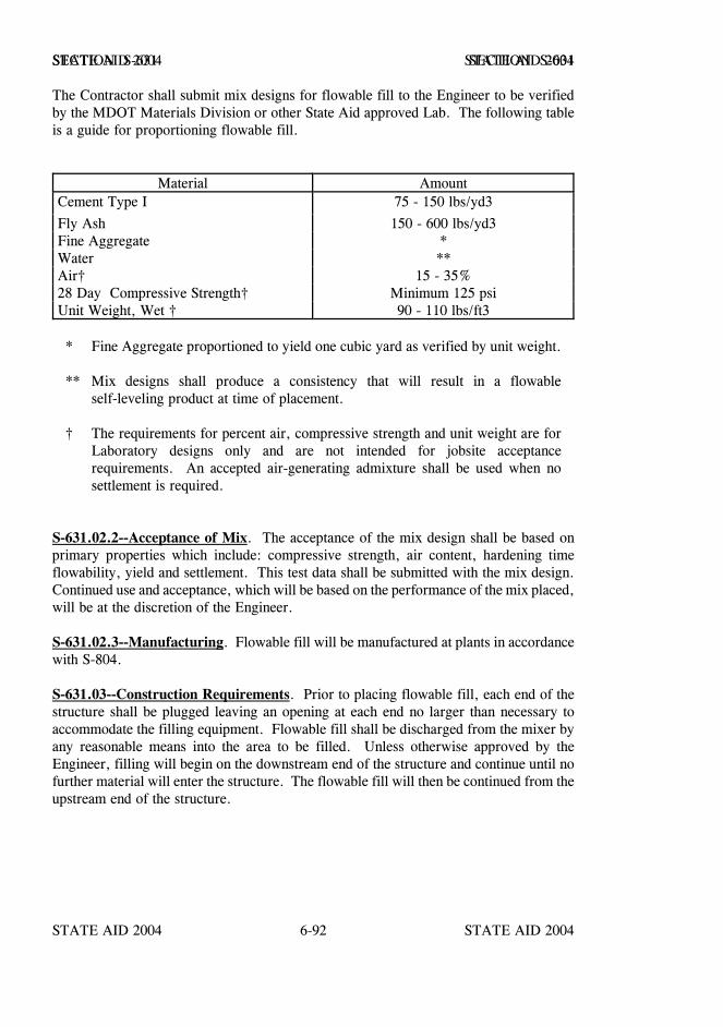
STATE AID 2004 STATE AID 2004
STATE AID 2004 STATE AID 20046-92
SECTION S-631 SECTION S-631
The Contractor shall submit mix designs for flowable fill to the Engineer to be verifiedby the MDOT Materials Division or other State Aid approved Lab. The following tableis a guide for proportioning flowable fill.
Material Amount Cement Type I 75 - 150 lbs/yd3
Fly Ash 150 - 600 lbs/yd3 Fine Aggregate * Water ** Air† 15 - 35% 28 Day Compressive Strength† Minimum 125 psi Unit Weight, Wet † 90 - 110 lbs/ft3
* Fine Aggregate proportioned to yield one cubic yard as verified by unit weight.
** Mix designs shall produce a consistency that will result in a flowableself-leveling product at time of placement.
† The requirements for percent air, compressive strength and unit weight are forLaboratory designs only and are not intended for jobsite acceptancerequirements. An accepted air-generating admixture shall be used when nosettlement is required.
S-631.02.2--Acceptance of Mix. The acceptance of the mix design shall be based onprimary properties which include: compressive strength, air content, hardening timeflowability, yield and settlement. This test data shall be submitted with the mix design.Continued use and acceptance, which will be based on the performance of the mix placed,will be at the discretion of the Engineer.
S-631.02.3--Manufacturing. Flowable fill will be manufactured at plants in accordancewith S-804.
S-631.03--Construction Requirements. Prior to placing flowable fill, each end of thestructure shall be plugged leaving an opening at each end no larger than necessary toaccommodate the filling equipment. Flowable fill shall be discharged from the mixer byany reasonable means into the area to be filled. Unless otherwise approved by theEngineer, filling will begin on the downstream end of the structure and continue until nofurther material will enter the structure. The flowable fill will then be continued from theupstream end of the structure.
STATE AID 2004 STATE AID 2004
STATE AID 2004 STATE AID 20046-93
SECTION S-631 SECTION S-631
S-631.04--Method of Measurement. Flowable fill will be measured by the cubic yardwhich will be determined by calculating yield. The yield will be calculated by dividingthe actual batch weights of each load by the unit weight of the mix, which will bedetermined by testing the first load placed on each production day.
S-631.05--Basis of Payment. Flowable fill will be paid for at the contract unit price percubic yard which shall be full compensation for furnishing and placing the material, fordrilling and filling holes if necessary, furnishing all labor, equipment, tools and materialsnecessary to complete the work.
Payment will be made under:
S-631-A: Flowable Fill - per cubic yard
STATE AID 2004 STATE AID 2004
STATE AID 2004 STATE AID 20046-94
SECTION S-632 - ROADBED RECLAMATION
S-632.01--Description. Roadbed Reclamation shall consist of pulverizing and mixing theexisting asphalt pavement together with base, subbase, and/or subgrade materials withportland cement and water to produce a uniform mixture meeting density requirements toserve as a base course for the pavement. Preliminary pulverization of the asphalt pavementand preliminary mixing of the existing asphalt pavement together with base, subbase, and/orsubgrade materials are permitted.
The Contractor shall mix the cement-stabilized base only when the weather permits thecourse to be finished without interruption in the time specified.
The Contractor shall begin mixing only when the air temperature is above 40°F in the shade,and rising.
Seasonal limitations for Roadbed Reclamation shall coincide with seasonal limitations forcement stabilization.
S-632.02--Materials. Portland Cement used shall conform to the requirements of S-701.01.
S-632.03--Construction Requirements.
(a) Equipment.
The pulverizing and mixing shall be done with one or more machines thatproduce the required degree of pulverization and uniformity.
Other pieces of equipment that may be required are a motorized grader,cement spreading unit, water truck, and compaction equipment.
The Engineer will not approve specific equipment for this work prior to its useon the project but will require the Contractor to use equipment that willproduce a base course mixture meeting the requirements of thesespecifications.
(b) Length of Roadbed Allowed to Be Processed.
Except by written permission of the Engineer, the length of roadbedpulverized at any time shall not exceed the length that can be completelypulverized, mixed, compacted, cured and protected against damage by normalanticipated traffic in the same working day.

STATE AID 2004 STATE AID 2004
STATE AID 2004 STATE AID 20046-95
SECTION S-632 SECTION S-632
(c) Spreading of Cement.
The Engineer may require pulverization and shaping of the pulverized roadbedmaterials to produce the required section before the placement of the cement.Otherwise, cement may be spread either prior to the pulverization and mixingor after an initial pulverization.
The amount of cement required to be placed will be shown on the plans or asdetermined from soil tests. Spreading of the cement shall be done with aspreader truck or other approved means to insure a uniform distribution.Pneumatic application through a slotted pipe will not be permitted. The amountof cement placed shall not vary more than 5 % of the total amount required.
Cement shall be applied in a limited area so that all the operations can becontinuous and completed in daylight hours, within 3 hours of the applicationof the cement.
Only the equipment that is used in spreading and mixing will be allowed topass over the spread cement before it is mixed into the existing materials.Cement that has been displaced shall be replaced before mixing is started.
(d) Pulverizing and Mixing.
The width and depth of the required pulverizing and mixing will be shown onplans. The depth of pulverizing shall be controlled to insure that the finishedthickness will be within the required tolerance limits. Pulverizing and mixingmay be accomplished in one or more passes subject to meeting thepulverization and uniformity requirements of these specifications. Spreadingof cement prior to the pulverization and mixing is allowed and encouragedprovided the pulverization and mixing equipment do not create excessivedusting or displacement of the cement that would alter the uniform distributionof cement throughout the section.
The pulverizing and mixing shall breakup the existing roadbed to the extentthat 98% to 100% by weight, exclusive of gravel or stone particles, passes a2 inch sieve and a minimum of 95% passes a 1.5 inch sieve. The moisturecontent shall be maintained at a point that allows compaction to the requireddensity.

STATE AID 2004 STATE AID 2004
STATE AID 2004 STATE AID 20046-96
SECTION S-632 SECTION S-632
(e) Mixing Cement with Pulverized Materials.
The contractor may perform initial dry mixing of the cement with the existingroadbed materials or may inject moisture into the mixing chamber of themixing/pulverizing equipment during the first mixing. Water shall not beadded by a spray bar from a water truck directly onto the unmixed cementspread. The cement shall be thoroughly mixed with the pulverized roadbedmaterials to provide a uniform distribution of the cement throughout themixture.
(f) Mixing Water with Cement and Pulverized Materials.
If the contractor does not inject moisture into the mixing chamber of thepulverizer/mixer during the first mixing, the pulverizer/mixer shall then beused to mix water into the mixture of cement and pulverized roadbedmaterials. The mixing shall be completed in one or more continuous pass(es)of the mixing unit. The mixture of the water, cement and pulverized roadbedmaterials shall be within the tolerance limits of optimum moisture content andshall be in a condition suitable for immediate compaction without furthermixing or grading.
For mixing units that inject moisture into the mixing chamber, a gage or gagesshall be provided to allow the continuous monitoring of the amount of waterthat is applied. When the mixer will handle only a part of the roadbed width,the successive increments shall be of such length that the full width of treatedmaterial may be promptly mixed, compacted and finished, with not more than30 minutes between mixing adjacent lanes. The asphalt and cement mix shallnot remain undisturbed after mixing and before compaction for more than 30minutes.
When the uncompacted mixture is made too wet by the addition of too muchwater, or by rain, and the moisture content exceeds the specified tolerance forcompaction, the entire affected section may be remixed at the Contractor’sexpense in an effort to dry the mixture through aeration.
(g) Compaction and Finishing.
The pulverizing, mixing and compaction shall be a continuous operation. Thecompaction of the mixture of water, cement and roadbed materials shall beginwithin 30 minutes after the final mixing. The mixture shall be compacted to aminimum of 95% of the field laboratory maximum density. Compaction andfinishing shall be completed within a period of one hour after the final mixing.
STATE AID 2004 STATE AID 2004
STATE AID 2004 STATE AID 20046-97
SECTION S-632 SECTION S-632
Sheep foot rollers, pad foot rollers, or similar equipment, shall be used for thecompaction.
After the mixture has been compacted, the surface shall be shaped to therequired lines, grades, and cross sections to within the required tolerances.During the shaping, light scarifying may be necessary to prevent the formationof compaction planes. Broom dragging or clipping of the surface may berequired as a part of the process of shaping the surface during compaction. Thesurface material shall be maintained at the specified moisture content duringfinishing operations. The final compaction and finishing operations may bevaried, if necessary, to produce a smooth, dense surface free of surfacecompaction planes, cracks, ridges or loose material.
(h) Testing, Tolerance, and Deficiency Correction.
The thickness of the base will be checked by the Engineer at intervals of 3000feet, or more often if necessary. A tolerance of +/- 8 % from the plandesignated thickness at any point will be permitted. The average thickness ofthe base completed in one day shall not vary more than 6 % from the thicknessshown on the plans.
The finished surface shall not vary more than 1/2 inch from the design grade.The Contractor shall provide a straight edge and template and employees to usethem to check the surface as directed by the Engineer.
High spots in the finished surface may be corrected by motor grader or planerwithout additional compensation, provided the resulting thickness is within thetolerances listed above. Other areas outside allowable tolerance or deficientin density will be rejected and shall be reconstructed by the Contractor at hisown expense, including necessary cement. The amount of cement to be usedin reconstruction will be determined by the Engineer.
Measurements will be made promptly upon completion of compaction andfinishing in order that correction may be made before the mixture hashardened.
(i) Surface Moisture.
The finished surface shall be kept moist until the curing seal, surface treatmentor next pavement course is applied.

STATE AID 2004 STATE AID 2004
STATE AID 2004 STATE AID 20046-98
SECTION S-632 SECTION S-632
(j) Curing.
A bituminous curing seal shall be applied over the entire surface of theRoadbed Reclamation. The surface shall be protected from drying prior toapplication of the curing seal. The rate of application shall be from 0.20 to0.35 gallons per square yard. The completed Roadbed Reclamation shall becured for a minimum of one week after final compaction has been completedunless the next pavement course is applied prior to that time.
(k) Opening to Traffic.
Traffic shall be placed on the roadway as directed by the Engineer.
S-632.04--Method of Measurement. Roadbed Reclamation will be measured in units ofsquare yards. The length will be measured along the surface of the pavement. The widthshall be the width specified on the plans or in writing by the Engineer.
S-632.05--Basis of Payment. The contract unit price for Roadbed Reclamation shall be thefull price for furnishing all materials (cement, water), curing seal,equipment, tools, labor,and incidentals necessary to complete the work.
Payment will be made under:
S-632-A: Roadbed Reclamation - per square yard.
Sections S-633 thru S-699 - Blank.

STATE AID 2004 STATE AID 2004
STATE AID 2004 STATE AID 2004
SECTION S-700 - MATERIALS AND TESTS
Section Page
S-700 - MATERIALS AND TESTS 7-1
S-701 - HYDRAULIC CEMENT 7-8
S-702 - BITUMINOUS MATERIALS 7-10
S-703 - AGGREGATES 7-20
S-704 - AGGREGATE FOR DRAINAGE 7-39
S-705 - STONE BLANKET PROTECTION AND FILTER BLANKET MATERIALS 7-40
S-706 - MASONRY UNITS 7-42
S-707 - JOINT MATERIALS 7-44
S-708 - NON-METAL STRUCTURES AND CATTLEPASSES 7-52
S-709 - METAL PIPE 7-62
S-710 - PAINT 7-66
S-711 - REINFORCEMENT AND WIRE ROPE 7-78
S-712 - GUARDRAIL 7-84
S-713 - CONCRETE CURING MATERIALS AND ADMIXTURES 7-85
S-714 - MISCELLANEOUS MATERIALS 7-87
S-715 - ROADSIDE DEVELOPMENT MATERIALS 7-107
S-716 - MISCELLANEOUS METALS 7-116
S-717 - STRUCTURAL STEEL 7-119
S-718 - TIMBER AND DIMENSION LUMBER 7-130
S-719 - PILES 7-136
S-720 - PAVEMENT MARKING MATERIALS 7-138
S-721 - MATERIALS FOR SIGNING 7-153
S-722 - GEOGRIDS 7-164
S-723 - thru S-799 - Blank 7-165

STATE AID 2004 STATE AID 2004
STATE AID 2004 STATE AID 2004
STATE AID 2004 STATE AID 2004
STATE AID 2004 STATE AID 20047-1
SECTION S-700 - MATERIALS AND TESTS
S-700.01--General. Materials will be inspected and sampled in accordance with theOffice of State Aid Road Construction current S.O.P. pertaining to inspecting andsampling.
Unless otherwise provided, all materials furnished which are to remain in place after finalacceptance shall be new and unused before incorporation into the work, except thatcrushed reclaimed concrete pavement meeting the requirements of S-703, as amended,may be used to produce aggregate for all hot mix asphalt pavements. When allowed bythe specifications, Recycled Asphalt Pavement (RAP) may be used in the manufacture ofhot mix asphalt pavements. Other recycled products approved for use by MDOT StateMaterials Engineer may be incorporated in the work.
The Contractor shall maintain sufficient approved materials on hand so that delays to thework will not result from the necessary sampling, testing, and evaluation of test results.
Domestic steel, iron and wire products including prestressing cable and strand shall befurnished for incorporation in the work. All manufacturing processes, includingapplication of a coating, for these materials must occur domestically. However, pig ironand processed, pelletized, and reduced iron ore manufactured outside of the United Statesmay be used in the domestic manufacturing process for steel and/or iron products. Forthe purpose of this specification, the activity of coating is considered a manufacturingprocess. The material being applied as a coating is not covered under Buy America.Coating includes all processes which protect or enhance the value of the material to whichthe coating is applied, such as epoxy coating, galvanizing, painting, etc.
Domestic shall be understood to mean all States of the United States, District ofColumbia, Puerto Rico, American Samoa, Guam, the Virgin Islands and any other placesubject to the jurisdiction of the United States.
In the case of coatings for the above referenced domestic steel, iron and wire products,it shall be the Contractor's responsibility to forward to the MDOT State MaterialsEngineer a certified statement from those having applied a coating to thesematerials that the application of the coating occurred domestically.
It shall be Contractor's responsibility to forward to the MDOT State Materials Engineersuch acceptable certification from the manufacturer, or at the election of the MDOT StateMaterials Engineer, such certification may be acceptable directly from a manufacturerannually, or more often, when requested by the MDOT State Materials Engineer.
S-700.02--Glossary of Terms and Definitions.
Aggregate - Inert material such as sand, gravel, lightweight aggregates, broken stone,slag, or combinations thereof.
Argillaceous - Containing or consisting of clay.
STATE AID 2004 STATE AID 2004
STATE AID 2004 STATE AID 20047-2
SECTION S-700 SECTION S-700
Asphaltic Cement - A product of the refining of crude oil to form a residue which is usedusually without the addition of more than a small quantity of flux or any liquifying agentof a higher volatile material than the residue itself.
Calcareous Material - A material containing more than 50 percent calcium type material.
Cementitious Material - Portland cement, or blend of portland cement and pozzolanmaterial used as the bonding agent in portland cement concrete. Cementitious shall mean“as having cementing properties”.
Clay - The fraction of a soil finer than 0.005 mm that is more or less plastic when wet.
Compaction - The process of obtaining the density of a soil or material.
Contemplated Mean Value (CMV) - The CMV is the desirable average or target value thatis designated between extreme limits that are tolerable in materials or workmanship.
Crusher Run - The product of a crushing plant that has not been rescreened or separatedinto various sizes.
Cutback Asphalt - An asphaltic material obtained from the refining of petroleum by addingto or fluxing the residue from distillation with volatile petroleum fractions to produce auniform mixture which is capable of becoming quite fluid at relatively low temperatures.
Fineness Modulus - An empirical factor obtained by adding the total percentages ofaggregate retained on the Nos. 100, 50, 30, 16, 8, 4, 3/8", 3/4", 1 1/2", and 3" sievesand dividing the sum by 100.
Frame - The part of the work or materials for which the same quality characteristics arespecified, such as a base course, an aggregate stockpile, a hot bituminous pavementcourse, etc.
Gravel - The granular, pebbly material (usually retained on a No. 8 sieve) resulting fromthe natural disintegration of rock.
Increment - The smallest unit(s) set aside for the sampling and testing process.
Liquid Limit (LL) - The water content, expressed in percentage by weight of the ovendried soil, at which the soil passes from a plastic to a liquid state when subjected to astandard method of determining liquid limit of soils.
Loess - Wind-blown, yellowish-brown loam having little or no stratification.
Lot - A subdivision of a frame, representing a designated quantity of work or materials,and is the unit of such work or materials which will be accepted or rejected.

STATE AID 2004 STATE AID 2004
STATE AID 2004 STATE AID 20047-3
SECTION S-700 SECTION S-700
Mechanical Analysis - The determination of the size and grading of soil particles bystandard tests.
Optimum Moisture - The moisture content necessary to obtain the standard density of asoil.
Overburden - Refers to soil or similar material directly above a deposit of rock, sand,gravel, or select material.
Pea Gravel - That portion of uncrushed gravel passing a 3/8 inch sieve and retained ona No. 8 sieve.
Plastic Limit (PL) - The water content, expressed in percentage by weight of theoven-dried soil, at which a soil passes from a solid or semi-solid state to a plastic statewhen subjected to a standard method of determining plastic limit of soils.
Plasticity Index (PI) - The range of water content through which the soil remains in aplastic condition. This term is the numerical difference between the liquid limit andplastic limit and is a measure of cohesion.
Portland Cement Concrete - A concrete mixture composed of cementitious materials,water, fine aggregate, coarse aggregate and possibly admixture(s).
Sample - The portion taken from a lot and considered to represent the whole or adesignated portion of the lot. It may consist of one or more increments or a fractionalpart of one or more combined increments.
Sand - A fine granular material resulting from the natural or mechanical disintegration ofrock. Depending on its use, material may be classed as sand if it passes the 3/8inch, No. 4 or No. 10 sieve.
Sand Clay - A mixture of sand and clay often found blended so that their opposite qualitiestend to maintain a condition of stability under varying moisture contents.
Screenings - Broken rock, limestone, slag, or other material, including the dust, ofa size that will pass a 1/2 inch sieve.
Selected Material - Material from approved sources, for use in subbases, bases, or forother specified use.
Shale - A fissile rock formed by the consolidation of clay, mud, or silt having a finelystratified or laminated structure.
Shrinkage Limit (SL) - The maximum calculated water content of a soil at which areduction in water content will not cause a decrease in the volume of the soil mass.
STATE AID 2004 STATE AID 2004
STATE AID 2004 STATE AID 20047-4
SECTION S-700 SECTION S-700
Sieves - Sieves for testing purposes conforming to the requirements of the standardSpecifications for Sieves for Testing Purposes of the AASHTO Designation: M 92.
Silt - The finer particles of organic or rock substance, ranging in size from 0.05 mm to0.005 mm.
Slag - The nonmetallic product thrown off from molten ore or metal or other processesand used as fine or coarse aggregate.
Soil - A natural aggregate of mineral grains, with or without organic constituents, that canbe separated by gentle mechanical means such as agitation in water.
Spall - A relatively small piece or fragment broken from rock, concrete, or other material.
Specific Gravity - The ratio of the weight of a volume of some substance to the weight ofan equal volume of substance, usually water, taken as a standard or unit.
Standard Density (Standard Compaction) - The maximum dry unit weight in pounds percubic foot obtained by the compactive effort exerted under the applicable testdesignation as provided in S-700.03.
Sublot - The smallest unit(s) set aside from a lot for the sampling and testing process.
Test Portion - The actual quantity of material tested--may be in some instances the wholeof the sample or in other instances only a quartered or other portion of the sample.
Test Result - The value of the specified characteristic obtained from testing a single testportion.
Test Value - The value determined as being the test result when only one test is requiredto satisfy a specified condition, or the average of the test results on two or more testportions of a lot, or a designated portion thereof.
Volume Change (VC) - The decrease in volume of the soil mass when the water contentis reduced from a given percentage to the shrinkage limit.
Water-Cement Ratio - The ratio of the weight of water used, including free moisture inthe aggregate, to the weight of cementitious material.
Other Definitions - Other applicable definitions as prepared by the Special Committee onNomenclature and adopted by AASHTO.
STATE AID 2004 STATE AID 2004
STATE AID 2004 STATE AID 20047-5
SECTION S-700 SECTION S-700
S-700.03--Sampling and Testing. Sampling and testing for acceptance and control ofmaterials may be performed at any time prior to incorporation in the work. Sampling andtesting for control and acceptance of a work item will be performed progressively assections of the work item are being constructed or completed, as applicable.
Unless otherwise designated, all tests will be made in accordance with applicable standardmethods of AASHTO, ASTM, Federal Specifications, or approved Mississippi TestMethods (MT ) in effect on the date of advertisement for bids. Note: It iscontemplated that certain methods of testing will be developed by MDOT. These willgenerally consist of minor revisions of AASHTO or ASTM Methods and will be designedto more nearly fit local conditions. Such methods are designated MT . As suchmethods are developed, approved, and issued, they will be used as standards in fieldtesting or in the Central Laboratory or other approved Laboratory, as designated in themethod, on projects advertised subsequent to their approval and issuance.
Material requiring specified tests used by a plant for producing composite material(s) orproduct(s) to be used in the work will be tested and approved by the Engineer. If suchmaterials, composite materials, or products are stored separately for the exclusive use inthe work, the cost of testing will be borne by the Project. If such materials, compositematerials or products are not stored separately for the exclusive use in the work, the costof testing shall be borne as set out in the Office of State Aid Road Construction’s issuedSOP in effect at the time bids are received.
S-700.04–Determination of Conformity. The determination of conformity with eachrequired measurable characteristic under the intent of S-105.03 will be made inaccordance with the following:
All test values or test results used to determine compliance will be rounded off to thenearest decimal point as expressed in the specification for the particular characteristicunder consideration. Fractions beyond the point of rounding amounting to less than 0.50will be dropped. Similar fractions amounting to more than 0.50 will be rounded off byincreasing the last digit within the rounding. Similar fractions, amounting to even 0.50will be rounded toward the specifications by dropping, or by increasing the last digitwithin the rounding, as applicable.
The various frames of materials or work will be divided into lots as specified in thecontract or conforming to the Office of State Aid Road Construction's S.O.P. forfrequency of sampling and testing.
In the case of borderline quality products or a demonstrated trend toward borderlinequality products, the Engineer will require the Contractor to improve the quality of thematerials or work to more nearly conform to the specifications and may require asuspension of the operations which have resulted in the borderline product or the trendtoward borderline quality until such corrective measures have been taken as deemednecessary to produce the contemplated quality products.
STATE AID 2004 STATE AID 2004
STATE AID 2004 STATE AID 20047-6
SECTION S-700 SECTION S-700
All increments of tests for determination of acceptance will be taken by random sampling.However, during or as a result of visual inspection, the Engineer will take increments fortesting for progress checks or spot checks at any time and place he may deem necessaryto determine weak spots or other progress information. The results of any such progressor spot checks may be used to determine whether or not additional work or correctiveaction is considered necessary prior to acceptance testing.
Minimum and maximum requirements in these specifications are set out on the basis thatthe desirable average test value of the materials or work is appreciably above theminimum requirement or appreciably below the maximum requirement established.
S-700.05--Material Certifications and Certified Test Reports. All certifications andcertified test reports shall meet the requirements set forth herein except certificationrequirements for cement and asphalt are set out separately in State Aid’s SOP.
S-700.05.1--Certifications. All certifications shall:
(a) Have letterhead of the manufacturer, producer, supplier, or fabricator.
(b) Include the project number.
(c) Itemized list of materials covered by the certification.
(d) Contain a material conformance statement which certifies that thematerials conform to the specific specification requirements. Example:I/We hereby certify the materials listed herein conform to therequirements of S-714.13 of the Mississippi Standard Specifications forState Aid Road and Bridge Construction.
(e) Certification for all iron, steel and steel wire products must also includea certified statement by the manufacturer that all of the manufacturingprocesses, excluding those for pig iron and processed, pelletized, andreduced iron ore used in the manufacture of said steel and/or ironproducts, have occurred domestically.
(f) Signature of a responsible company official.
STATE AID 2004 STATE AID 2004
STATE AID 2004 STATE AID 20047-7
SECTION S-700 SECTION S-700
S-700.05.2--Certified Test Reports. All certified test reports shall:
(a) Have letterhead of the manufacturer, producer, supplier, fabricator, orlaboratory.
(b) Include name and description of material, lot, batch or heat number,etc., as applicable.
(d) Show results of each required test, and state that the test was runaccording to the test method specified.
(e) Test reports for all iron, steel and steel wire products must also includea certified statement by the manufacturer that all of the manufacturingprocesses, excluding those for pig iron and processed, pelletized, andreduced iron ore used in the manufacture of said steel and/or ironproducts, have occurred domestically.
(f) Signature of the responsible laboratory official.
STATE AID 2004 STATE AID 2004
STATE AID 2004 STATE AID 20047-8
SECTION S-701 - HYDRAULIC CEMENT
S-701.00--General. The following requirements shall be applicable to hydraulic cement:
1. Different brands of cement, or the same brand of cement from differentmills, shall not be mixed or used alternately in any one class ofconstruction or structure, without written permission from theEngineer; except that this requirement will not be applicable to cementtreatment of design soils, subbases, or bases.
2. The Contractor shall provide suitable means for storing and protectingthe cement against dampness. Cement, which for any reason, hasbecome partially set or which contains lumps of caked cement will berejected. Cement salvaged from discarded or used bags shall not beused.
3. The temperature of bulk cement shall not be greater than 165oF at thetime of incorporation in the mix.
4. One barrel (bbl) of cement shall be equivalent to four bags or 376pounds.
5. Low-alkali cement, with maximum sodium and potassium oxides of0.6%, will be furnished in all types.
6. Except when otherwise specified or prohibited, either Type I, IP or IIportland cement shall be used. Type III portland cement may be usedin the production of precast or prestressed concrete members.
7. Acceptance of hydraulic cement will be based on the certificationprogram and job control sampling and testing as established in theSOP.
8. Retests of cement may be made for soundness and expansion within 28days of test failure and, if the cement passes, it may be accepted.Cement shall not be rejected due to failure to meet the finenessrequirements if upon retests after drying at 100oC for one hour, itmeets such requirements.
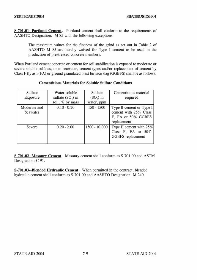
STATE AID 2004 STATE AID 2004
STATE AID 2004 STATE AID 20047-9
SECTION S-701 SECTION S-701
S-701.01--Portland Cement. Portland cement shall conform to the requirements ofAASHTO Designation: M 85 with the following exceptions:
The maximum values for the fineness of the grind as set out in Table 2 ofAASHTO M 85 are hereby waived for Type I cement to be used in theproduction of prestressed concrete members.
When Portland cement concrete or cement for soil stabilization is exposed to moderate orsevere soluble sulfates, or to seawater, cement types and/or replacement of cement byClass F fly ash (FA) or ground granulated blast furnace slag (GGBFS) shall be as follows:
Cementitious Materials for Soluble Sulfate Conditions
SulfateExposure
Water-solublesulfate (SO4) insoil, % by mass
Sulfate(SO4) in
water, ppm
Cementitious materialrequired
Moderate andSeawater
0.10 - 0.20 150 - 1500 Type II cement or Type Icement with 25% ClassF, FA or 50% GGBFSreplacement
Severe 0.20 - 2.00 1500 - 10,000 Type II cement with 25%Class F, FA or 50%GGBFS replacement
S-701.02--Masonry Cement. Masonry cement shall conform to S-701.00 and ASTMDesignation: C 91.
S-701.03--Blended Hydraulic Cement. When permitted in the contract, blendedhydraulic cement shall conform to S-701.00 and AASHTO Designation: M 240.
STATE AID 2004 STATE AID 2004
STATE AID 2004 STATE AID 20047-10
SECTION S-702 - BITUMINOUS MATERIALS
S-702.00–Bituminous Materials.
S-702.01--General. Bituminous materials shall include asphalt cement, cutback asphalt,or emulsified asphalt and shall meet the requirements of the applicable specifications. Thematerial furnished for any item in any one contract shall be of one brand, type, and grade,unless special permission is obtained otherwise. Materials furnished shall exhibit uniformcharacteristics.
When more than one grade of material is called for under any item, the Contractor, withthe approval of the Engineer, will select the grade to be used.
All sampling and reporting of bituminous materials shall be performed as set out in theOffice of State Aid Road Construction SOP. All testing will be performed in accordancewith applicable AASHTO methods unless specifically modified by a Mississippi TestMethod (MT ).
Bituminous material shall not be heated during the process of its manufacture, or duringconstruction, to a temperature which causes injury as evidenced by the formation ofcarbonized particles.
Bituminous material wasted through careless handling or material that has been renderedunfit for use by overheating or long continued heating will not be paid for, and the useof such unfit material will not be permitted.
S-702.02--Measurement. Volumetric measurement of bituminous materials by the U.S.gallon will be based upon a temperature of 60°F. Corrections to this temperature forasphalt cement, cutback asphalts and emulsified asphalt will be made in accordance withthe Temperature Correction Tables set out in the State Aid Standard OperatingProcedures.
For purposes of measurement, a U.S. gallon shall be a volume of 231 cubic inches.
When bituminous material is to be paid for by the gallon, the distributor tank(s) or storagetank(s), as applicable, to be used for measurement shall be calibrated by an agency andin a manner approved by MDOT. A calibration chart, showing the dimensions andvolume per inch of depth, and a measuring gauge, calibrated in inches, shall be furnishedthe Engineer. Each tank shall have an identifying serial number on a steel plate weldedor riveted to the tank. In the event the Contractor does not have such calibration chart,previously made by an approved agency, MDOT will, upon request, perform thecalibration and furnish required charts; however, the Contractor will be fully responsiblefor any delays occasioned by such calibration by MDOT.
STATE AID 2004 STATE AID 2004
STATE AID 2004 STATE AID 20047-11
SECTION S-702 SECTION S-702
The measurements shall be taken when the bituminous material is of a uniformtemperature and free of air bubbles. In no case shall the total number of gallons ofbituminous material allowed for a tank exceed the capacity of the tank as rated by eitherthe U. S. Interstate Commerce Commission, the State Tax Commission, or MDOT.
S-702.03--Heating Bituminous Material. Tanks for heating and storage of bituminousmaterials shall be capable of heating the material to the specified temperature undereffective and positive control at all times. The heating system shall provide uniformheating for the entire contents of the tank. The circulating system shall be adequate toinsure proper and continuous circulation of the material during the entire operating period.Suitable means shall be provided, either by steamjacketing or other insulation, formaintaining the specified temperature of the bituminous material in the lines, meters,weigh buckets, spray bars, and other containers or flow lines.
Thermometers of approved type and adequate range, calibrated in 5oF increments, shallbe located at points readily visible. These thermometers shall be kept clean and in goodcondition at all times.
Where storage tanks are required, the capacity shall be sufficient for at least one day'srun.
The heating of bituminous materials shall be rigidly maintained at the "lowest workabletemperature."
S-702.04--Sampling. Sampling of bituminous materials will be in accordance withAASHTO Designation: T 40.
S-702.05--Petroleum Asphalt Cement. Asphalt cement shall be homogeneous, free ofwater and shall not foam when heated to a temperature of 175°C.
Except for use in hot mix asphalt, asphalt cement of the grade specified shall conform tothe requirements of S-702.12, Table I or II.
Bituminous material conforming to AASHTO Designation: M 320, Grade PG 58-28 maybe used in lieu of petroleum asphalt cement, Grade AC-10.
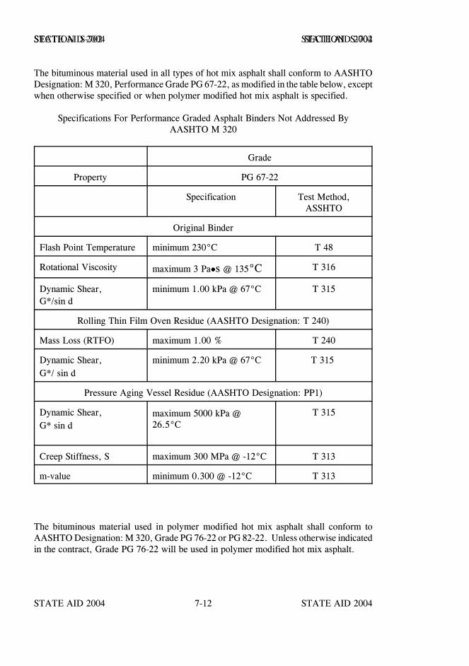
STATE AID 2004 STATE AID 2004
STATE AID 2004 STATE AID 20047-12
SECTION S-702 SECTION S-702
The bituminous material used in all types of hot mix asphalt shall conform to AASHTODesignation: M 320, Performance Grade PG 67-22, as modified in the table below, exceptwhen otherwise specified or when polymer modified hot mix asphalt is specified.
Specifications For Performance Graded Asphalt Binders Not Addressed ByAASHTO M 320
Grade
Property PG 67-22
Specification Test Method,ASSHTO
Original Binder
Flash Point Temperature minimum 230°C T 48
Rotational Viscosity maximum 3 Pa s @ 135°C T 316
Dynamic Shear,G*/sin d
minimum 1.00 kPa @ 67°C T 315
Rolling Thin Film Oven Residue (AASHTO Designation: T 240)
Mass Loss (RTFO) maximum 1.00 % T 240
Dynamic Shear,G*/ sin d
minimum 2.20 kPa @ 67°C T 315
Pressure Aging Vessel Residue (AASHTO Designation: PP1)
Dynamic Shear,G* sin d
maximum 5000 kPa @26.5°C
T 315
Creep Stiffness, S maximum 300 MPa @ -12°C T 313
m-value minimum 0.300 @ -12°C T 313
The bituminous material used in polymer modified hot mix asphalt shall conform toAASHTO Designation: M 320, Grade PG 76-22 or PG 82-22. Unless otherwise indicatedin the contract, Grade PG 76-22 will be used in polymer modified hot mix asphalt.
STATE AID 2004 STATE AID 2004
STATE AID 2004 STATE AID 20047-13
SECTION S-702 SECTION S-702
Asphalt cement Grade PG 76-22 & PG 82-22 shall be the product resulting from theaddition of a polymer modifier to a PG 67-22 or lower grade asphalt cement and not bysome other refining technique. The polymer shall meet the requirements of S-702.08.3.
S-702.06--Cutback Asphalts. Cutback asphalt shall consist of a liquid asphalt producedby the fluxing of an asphaltic base with a suitable distillate. It shall be of uniformconsistency, free of water, and shall show no separation or curdling prior to use; and shallconform to the following requirements.
S-702.06.1--Rapid-Curing Cutback Asphalt. AASHTO Designation: M 81.
S-702.06.2--Medium-Curing Cutback Asphalt. AASHTO Designation: M 82.
The standard naphtha solvent shall be used when the spot test is performed.
S-702.07--Emulsified Asphalt. Emulsified asphalt shall be homogeneous, showing noseparation of asphalt, limits for settlement excepted, after thorough mixing, within 30days after delivery.
Emulsified asphalts which have been subjected to freezing temperatures while in storageshall be retested and acceptance of the material shall be based on the results of such retest.
Emulsified asphalts, of the grade specified, shall conform to the following requirements:
S-702.07.1--Emulsified Primes. Emulsified Primes shall conform to the requirementsof S-702.12, Table III.
S-702.07.2--Anionic and Cationic. Anionic and Cationic Emulsion shall conform to therequirements of AASHTO Designation: M 140 and AASHTO Designation: M 208,respectively, with the following exceptions.
Exception: The required tests on residue may be performed on residue obtained byevaporation at 325°F., three hours, 50 grams, after filtering through a No. 50 sieve;however, in the event of the failure of any test performed on this residue, the emulsionshall be distilled and the test repeated on the residue so obtained.
S-702.07.3--Polymer Modified Cationic Emulsified Asphalt (CRS-2P). PolymerModified Cationic Emulsified Asphalt shall conform to the requirements of AASHTODesignation: M 316.
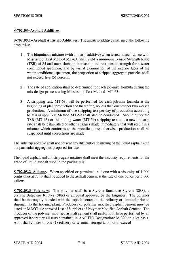
STATE AID 2004 STATE AID 2004
STATE AID 2004 STATE AID 20047-14
SECTION S-702 SECTION S-702
S-702.08--Asphalt Additives.
S-702.08.1--Asphalt Antistrip Additives. The antistrip additive shall meet the followingproperties:
1. The bituminous mixture (with antistrip additive) when tested in accordance withMississippi Test Method MT-63, shall yield a minimum Tensile Strength Ratio(TSR) of 85 and must show an increase in indirect tensile strength for a waterconditioned specimen; and by visual examination of the interior faces of thewater conditioned specimen, the proportion of stripped aggregate particles shallnot exceed five (5) percent.
2. The rate of application shall be determined for each job-mix formula during themix design process using Mississippi Test Method MT-63.
3. A stripping test, MT-63, will be performed for each job-mix formula at thebeginning of plant production and thereafter, no less than one test per two week'sproduction. A minimum of one stripping test per day of production accordingto Mississippi Test Method MT-59 shall also be conducted. Should either theTSR (MT-63) or the boiling water (MT-59) stripping test fail, a new antistriprate shall be established or other changes made immediately that will result in amixture which conforms to the specifications; otherwise, production shall besuspended until corrections are made.
The antistrip additive shall not present any difficulties in mixing of the liquid asphalt withthe particular aggregates proposed for use.
The liquid asphalt and antistrip agent mixture shall meet the viscosity requirements for thegrade of liquid asphalt used in the paving mix.
S-702.08.2--Silicone. When specified or permitted, silicone with a viscosity of 1,000centistokes at 77°F shall be added to the asphalt cement at the rate of one ounce per 5,000gallons.
S-702.08.3--Polymers. The polymer shall be a Styrene Butadiene Styrene (SBS), aStyrene Butadiene Rubber (SBR) or an equal approved by the Engineer. The polymershall be thoroughly blended with the asphalt cement at the refinery or terminal prior toshipment to the hot-mix plant. Producers of polymer modified asphalt cement must belisted on MDOT’s Approved List of Suppliers of Polymer Modified Asphalt Cement. Theproducer of the polymer modified asphalt cement shall perform or have performed by anapproved laboratory all tests contained in AASHTO Designation: M 320 on a lot basis.A lot shall consist of one (1) refinery or terminal storage tank not to exceed
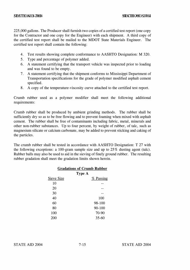
STATE AID 2004 STATE AID 2004
STATE AID 2004 STATE AID 20047-15
SECTION S-702 SECTION S-702
225,000 gallons. The Producer shall furnish two copies of a certified test report (one copyfor the Contractor and one copy for the Engineer) with each shipment. A third copy ofthe certified test report shall be mailed to the MDOT State Materials Engineer. Thecertified test report shall contain the following:
4. Test results showing complete conformance to AASHTO Designation: M 320.5. Type and percentage of polymer added.6. A statement certifying that the transport vehicle was inspected prior to loading
and was found to be empty.7. A statement certifying that the shipment conforms to Mississippi Department of
Transportation specifications for the grade of polymer modified asphalt cementspecified.
8. A copy of the temperature-viscosity curve attached to the certified test report.
Crumb rubber used as a polymer modifier shall meet the following additionalrequirements:
Crumb rubber shall be produced by ambient grinding methods. The rubber shall besufficiently dry so as to be free flowing and to prevent foaming when mixed with asphaltcement. The rubber shall be free of contaminants including fabric, metal, minerals andother non-rubber substances. Up to four percent, by weight of rubber, of talc, such asmagnesium silicate or calcium carbonate, may be added to prevent sticking and caking ofthe particles.
The crumb rubber shall be tested in accordance with AASHTO Designation: T 27 withthe following exceptions: a 100-gram sample size and up to 25% dusting agent (talc).Rubber balls may also be used to aid in the sieving of finely ground rubber. The resultingrubber gradation shall meet the gradation limits shown herein.
Gradations of Crumb RubberType A
Sieve Size % Passing 10 -- 20 -- 30 -- 40 100 60 98-100 80 90-100 100 70-90 200 35-60
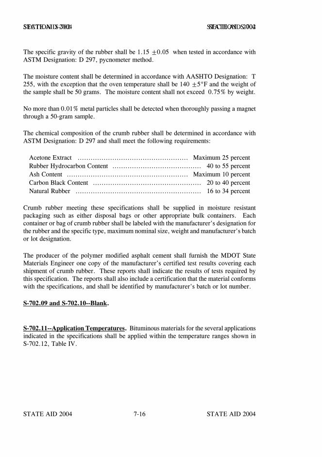
STATE AID 2004 STATE AID 2004
STATE AID 2004 STATE AID 20047-16
SECTION S-702 SECTION S-702
The specific gravity of the rubber shall be 1.15 ±0.05 when tested in accordance withASTM Designation: D 297, pycnometer method.
The moisture content shall be determined in accordance with AASHTO Designation: T255, with the exception that the oven temperature shall be 140 ±5°F and the weight ofthe sample shall be 50 grams. The moisture content shall not exceed 0.75% by weight.
No more than 0.01% metal particles shall be detected when thoroughly passing a magnetthrough a 50-gram sample.
The chemical composition of the crumb rubber shall be determined in accordance withASTM Designation: D 297 and shall meet the following requirements:
Acetone Extract ................................................... Maximum 25 percentRubber Hydrocarbon Content ......................................... 40 to 55 percentAsh Content ........................................................ Maximum 10 percentCarbon Black Content .................................................. 20 to 40 percentNatural Rubber .......................................................... 16 to 34 percent
Crumb rubber meeting these specifications shall be supplied in moisture resistantpackaging such as either disposal bags or other appropriate bulk containers. Eachcontainer or bag of crumb rubber shall be labeled with the manufacturer's designation forthe rubber and the specific type, maximum nominal size, weight and manufacturer's batchor lot designation.
The producer of the polymer modified asphalt cement shall furnish the MDOT StateMaterials Engineer one copy of the manufacturer’s certified test results covering eachshipment of crumb rubber. These reports shall indicate the results of tests required bythis specification. The reports shall also include a certification that the material conformswith the specifications, and shall be identified by manufacturer's batch or lot number.
S-702.09 and S-702.10--Blank.
S-702.11--Application Temperatures. Bituminous materials for the several applicationsindicated in the specifications shall be applied within the temperature ranges shown inS-702.12, Table IV.
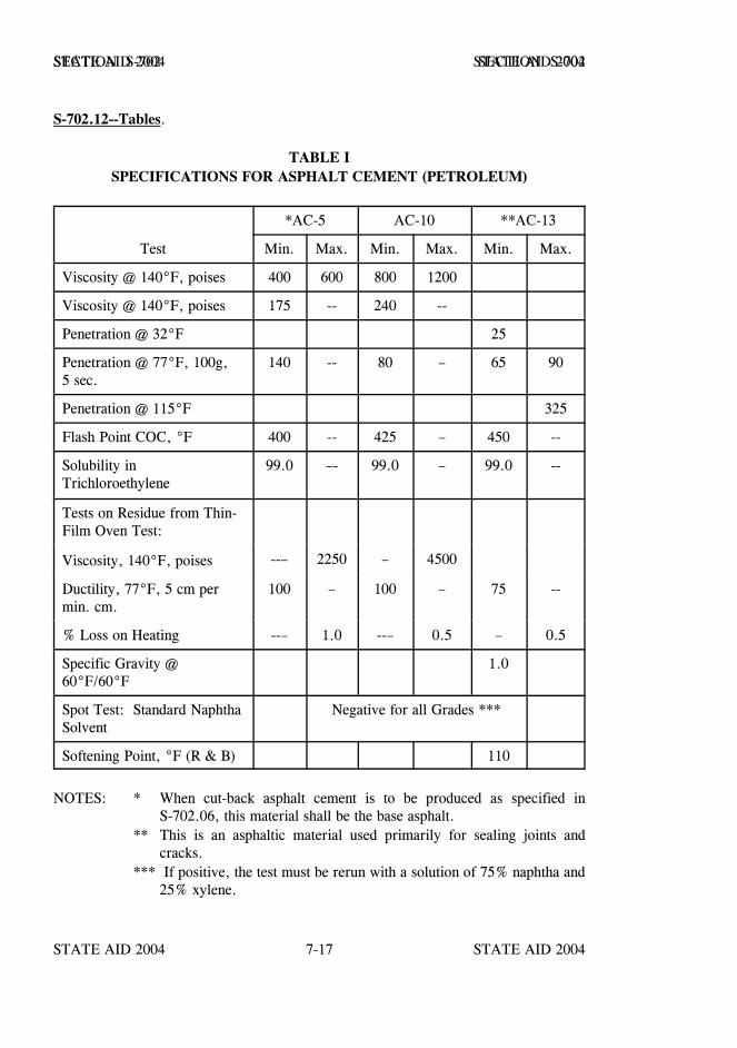
STATE AID 2004 STATE AID 2004
STATE AID 2004 STATE AID 20047-17
SECTION S-702 SECTION S-702
S-702.12--Tables.
TABLE ISPECIFICATIONS FOR ASPHALT CEMENT (PETROLEUM)
Test
*AC-5 AC-10 **AC-13
Min. Max. Min. Max. Min. Max.
Viscosity @ 140°F, poises 400 600 800 1200
Viscosity @ 140°F, poises 175 -- 240 --
Penetration @ 32°F 25
Penetration @ 77°F, 100g, 5 sec.
140 -- 80 – 65 90
Penetration @ 115°F 325
Flash Point COC, °F 400 -- 425 – 450 --
Solubility inTrichloroethylene
99.0 –- 99.0 – 99.0 --
Tests on Residue from Thin-Film Oven Test:
Viscosity, 140°F, poises --– 2250 – 4500
Ductility, 77°F, 5 cm permin. cm.
100 – 100 – 75 --
% Loss on Heating --– 1.0 --– 0.5 – 0.5
Specific Gravity @60°F/60°F
1.0
Spot Test: Standard NaphthaSolvent
Negative for all Grades ***
Softening Point, °F (R & B) 110
NOTES: * When cut-back asphalt cement is to be produced as specified inS-702.06, this material shall be the base asphalt.
** This is an asphaltic material used primarily for sealing joints andcracks.
*** If positive, the test must be rerun with a solution of 75% naphtha and25% xylene.
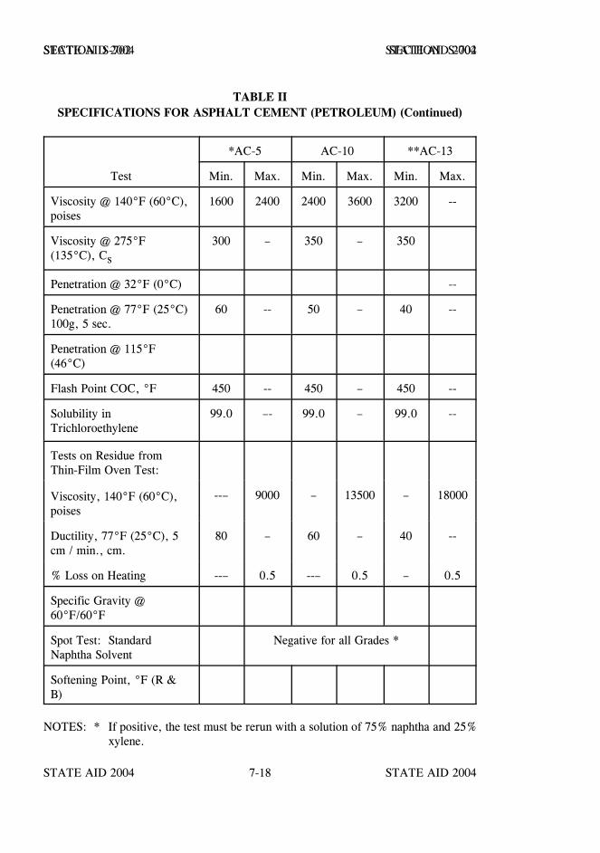
STATE AID 2004 STATE AID 2004
STATE AID 2004 STATE AID 20047-18
SECTION S-702 SECTION S-702
TABLE IISPECIFICATIONS FOR ASPHALT CEMENT (PETROLEUM) (Continued)
Test
*AC-5 AC-10 **AC-13
Min. Max. Min. Max. Min. Max.
Viscosity @ 140°F (60°C),poises
1600 2400 2400 3600 3200 --
Viscosity @ 275°F(135°C), Cs
300 – 350 – 350
Penetration @ 32°F (0°C) --
Penetration @ 77°F (25°C)100g, 5 sec.
60 -- 50 – 40 --
Penetration @ 115°F(46°C)
Flash Point COC, °F 450 -- 450 – 450 --
Solubility inTrichloroethylene
99.0 –- 99.0 – 99.0 --
Tests on Residue fromThin-Film Oven Test:
Viscosity, 140°F (60°C),poises
--– 9000 – 13500 – 18000
Ductility, 77°F (25°C), 5cm / min., cm.
80 – 60 – 40 --
% Loss on Heating --– 0.5 --– 0.5 – 0.5
Specific Gravity @60°F/60°F
Spot Test: StandardNaphtha Solvent
Negative for all Grades *
Softening Point, °F (R &B)
NOTES: * If positive, the test must be rerun with a solution of 75% naphtha and 25%xylene.
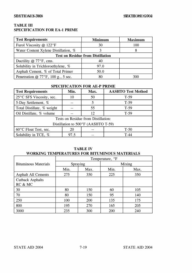
STATE AID 2004 STATE AID 2004
STATE AID 2004 STATE AID 20047-19
SECTION S-702 SECTION S-702
TABLE IIISPECIFICATION FOR EA-1 PRIME
Test Requirements Minimum MaximumFurol Viscosity @ 122°F 30 100Water Content Xylene Distillation, % 3 8
Test on Residue from DistillationDuctility @ 77°F, cms. 40Solubility in Trichloroethylene, % 97.0Asphalt Cement, % of Total Primer 50.0Penetration @ 77°F, 100 g., 5 sec. 80 300
SPECIFICATION FOR AE-P PRIMETest Requirements Min. Max. AASHTO Test Method25°C SFS Viscosity, sec. 10 50 T-595-Day Settlement, % -- 5 T-59Total Distillate, % weight -- 55 T-59Oil Distillate, % volume -- 12 T-59
Tests on Residue from Distillation:Distillation to 500°F (AASHTO T-59)
60°C Float Test, sec. 20 -- T-50Solubility in TCE, % 97.5 -- T-44
TABLE IVWORKING TEMPERATURES FOR BITUMINOUS MATERIALS
Temperature, °FBituminous Materials Spraying Mixing
Min. Max. Min. Max.Asphalt All Cements 275 350 225 350Cutback AsphaltsRC & MC30 80 150 60 10570 80 150 95 140250 100 200 135 175800 195 270 165 2053000 235 300 200 240
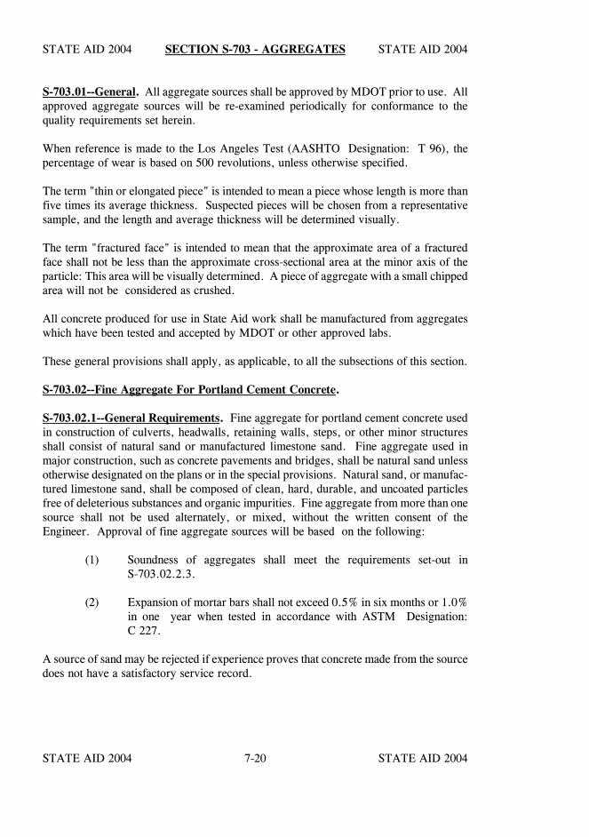
STATE AID 2004 STATE AID 2004
STATE AID 2004 STATE AID 20047-20
SECTION S-703 - AGGREGATES
S-703.01--General. All aggregate sources shall be approved by MDOT prior to use. Allapproved aggregate sources will be re-examined periodically for conformance to thequality requirements set herein.
When reference is made to the Los Angeles Test (AASHTO Designation: T 96), thepercentage of wear is based on 500 revolutions, unless otherwise specified.
The term "thin or elongated piece" is intended to mean a piece whose length is more thanfive times its average thickness. Suspected pieces will be chosen from a representativesample, and the length and average thickness will be determined visually.
The term "fractured face" is intended to mean that the approximate area of a fracturedface shall not be less than the approximate cross-sectional area at the minor axis of theparticle: This area will be visually determined. A piece of aggregate with a small chippedarea will not be considered as crushed.
All concrete produced for use in State Aid work shall be manufactured from aggregateswhich have been tested and accepted by MDOT or other approved labs.
These general provisions shall apply, as applicable, to all the subsections of this section.
S-703.02--Fine Aggregate For Portland Cement Concrete.
S-703.02.1--General Requirements. Fine aggregate for portland cement concrete usedin construction of culverts, headwalls, retaining walls, steps, or other minor structuresshall consist of natural sand or manufactured limestone sand. Fine aggregate used inmajor construction, such as concrete pavements and bridges, shall be natural sand unlessotherwise designated on the plans or in the special provisions. Natural sand, or manufac-tured limestone sand, shall be composed of clean, hard, durable, and uncoated particlesfree of deleterious substances and organic impurities. Fine aggregate from more than onesource shall not be used alternately, or mixed, without the written consent of theEngineer. Approval of fine aggregate sources will be based on the following:
(1) Soundness of aggregates shall meet the requirements set-out inS-703.02.2.3.
(2) Expansion of mortar bars shall not exceed 0.5% in six months or 1.0%in one year when tested in accordance with ASTM Designation:C 227.
A source of sand may be rejected if experience proves that concrete made from the sourcedoes not have a satisfactory service record.
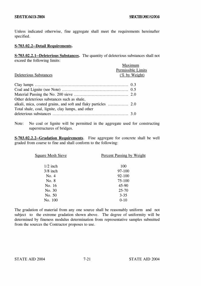
STATE AID 2004 STATE AID 2004
STATE AID 2004 STATE AID 20047-21
SECTION S-703 SECTION S-703
Unless indicated otherwise, fine aggregate shall meet the requirements hereinafterspecified.
S-703.02.2--Detail Requirements.
S-703.02.2.1--Deleterious Substances. The quantity of deleterious substances shall notexceed the following limits:
MaximumPermissible Limits
Deleterious Substances (% by Weight)
Clay lumps ..................................................................... 0.3Coal and Lignite (see Note) ................................................. 0.5Material Passing the No. 200 sieve ........................................ 2.0Other deleterious substances such as shale, alkali, mica, coated grains, and soft and flaky particles ............... 2.0Total shale, coal, lignite, clay lumps, and other deleterious substances ........................................................ 3.0
Note: No coal or lignite will be permitted in the aggregate used for constructingsuperstructures of bridges.
S-703.02.2.2--Gradation Requirements. Fine aggregate for concrete shall be wellgraded from coarse to fine and shall conform to the following:
Square Mesh Sieve Percent Passing by Weight
1/2 inch3/8 inchNo. 4No. 8No. 16No. 30No. 50No. 100
10097-10092-10075-10045-9025-703-350-10
The gradation of material from any one source shall be reasonably uniform and notsubject to the extreme gradation shown above. The degree of uniformity will bedetermined by fineness modulus determination from representative samples submittedfrom the sources the Contractor proposes to use.
STATE AID 2004 STATE AID 2004
STATE AID 2004 STATE AID 20047-22
SECTION S-703 SECTION S-703
Fine aggregate from any one source having a variation in fineness modulus greater than0.20 from the approved base modulus of the source may be rejected or may be acceptedsubject to changes in the proportions, if and as directed by the Engineer.
When the slip-form method for placement of concrete pavement is used, the fine aggregategradation requirements will be modified if necessary.
S-703.02.2.3--Soundness. When subjected to five cycles of soundness test by the use ofmagnesium sulfate (AASHTO Designation: T 104), the weighed percentage of loss shallnot be more than 15.
S-703.02.2.4--Additional Requirements. Fine aggregate shall also meet the organicimpurities and mortar-making properties specified in AASHTO Designation: M 6.
S-703.03--Coarse Aggregate For Portland Cement Concrete.
S-703.03.1--General Requirements. Coarse aggregate shall consist of gravel or crushedlimestone unless otherwise designated or permitted on the plans or in special provisions.
The gravel or crushed limestone shall be hard, durable particles that are thoroughly clean,free from adherent coatings of injurious character, and reasonably free of soft ordisintegrated pieces, frozen lumps, vegetable, or other deleterious matter. Coarseaggregate from more than one source shall not be used alternately, or mixed, without thewritten approval of the Engineer. Approval of coarse aggregate sources will be based onthe following:
(1) Soundness of aggregates shall meet the requirementsset out in S-703.03.2.3.
(2) Resistance to abrasion shall meet the requirements setout in S-703.03.2.2.
(3) Expansion of mortar bars shall not exceed 0.5% in sixmonths or 1.0% in one year when tested inaccordance with ASTM Designation: C 227.
A source of coarse aggregate may be rejected if experience proves that concrete madefrom the source does not have a satisfactory service record.
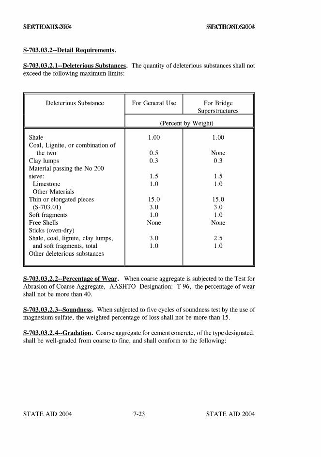
STATE AID 2004 STATE AID 2004
STATE AID 2004 STATE AID 20047-23
SECTION S-703 SECTION S-703
S-703.03.2--Detail Requirements.
S-703.03.2.1--Deleterious Substances. The quantity of deleterious substances shall notexceed the following maximum limits:
Deleterious Substance For General Use For BridgeSuperstructures
(Percent by Weight)
ShaleCoal, Lignite, or combination of the twoClay lumpsMaterial passing the No 200sieve: Limestone Other MaterialsThin or elongated pieces (S-703.01)Soft fragmentsFree ShellsSticks (oven-dry)Shale, coal, lignite, clay lumps, and soft fragments, totalOther deleterious substances
1.00
0.50.3
1.51.0
15.03.01.0
None
3.01.0
1.00
None0.3
1.51.0
15.03.01.0
None
2.51.0
S-703.03.2.2--Percentage of Wear. When coarse aggregate is subjected to the Test forAbrasion of Coarse Aggregate, AASHTO Designation: T 96, the percentage of wearshall not be more than 40.
S-703.03.2.3--Soundness. When subjected to five cycles of soundness test by the use ofmagnesium sulfate, the weighted percentage of loss shall not be more than 15.
S-703.03.2.4--Gradation. Coarse aggregate for cement concrete, of the type designated,shall be well-graded from coarse to fine, and shall conform to the following:
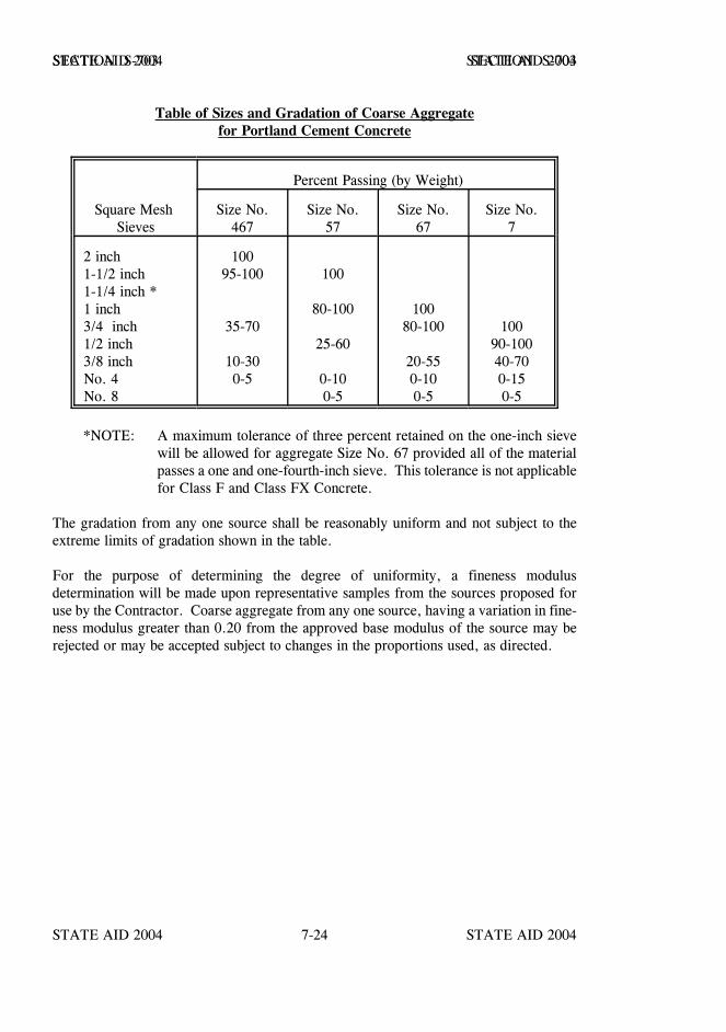
STATE AID 2004 STATE AID 2004
STATE AID 2004 STATE AID 20047-24
SECTION S-703 SECTION S-703
Table of Sizes and Gradation of Coarse Aggregatefor Portland Cement Concrete
Percent Passing (by Weight)
Square Mesh Sieves
Size No.467
Size No.57
Size No.67
Size No.7
2 inch1-1/2 inch1-1/4 inch *1 inch3/4 inch1/2 inch3/8 inchNo. 4No. 8
10095-100
35-70
10-300-5
100
80-100
25-60
0-100-5
10080-100
20-550-100-5
10090-10040-700-150-5
*NOTE: A maximum tolerance of three percent retained on the one-inch sievewill be allowed for aggregate Size No. 67 provided all of the materialpasses a one and one-fourth-inch sieve. This tolerance is not applicablefor Class F and Class FX Concrete.
The gradation from any one source shall be reasonably uniform and not subject to theextreme limits of gradation shown in the table.
For the purpose of determining the degree of uniformity, a fineness modulusdetermination will be made upon representative samples from the sources proposed foruse by the Contractor. Coarse aggregate from any one source, having a variation in fine-ness modulus greater than 0.20 from the approved base modulus of the source may berejected or may be accepted subject to changes in the proportions used, as directed.
STATE AID 2004 STATE AID 2004
STATE AID 2004 STATE AID 20047-25
SECTION S-703 SECTION S-703
S-703.04--Aggregate for Crushed Stone Courses.
S-703.04.1--Coarse Aggregate. Coarse aggregate, defined as material retained on No.8 sieve, shall be either crushed stone, slag, granite, shell; gravel, or combination thereof.When the required properties of the mix are not obtained with uncrushed gravel, theaddition of crushed gravel or other approved material is required.
Individual sources of coarse aggregate shall conform to the following qualityrequirements:
Percentage of wear shall not exceed 45 when tested in accordance with AASHTODesignation: T 96.
The coarse aggregate shall have a minimum dry rodded unit weight of 70 poundsper cubic foot when tested in accordance with AASHTO Designation: T 19.
S-703.04.2--Fine Aggregate. Fine aggregate, defined as material passing no. 8 sieve,shall consist of hard, durable particles of naturally disintegrated rock, or material obtainedby crushing stone, slag, gravel or combination thereof. Fine aggregate, whenmanufactured, shall be manufactured from material meeting the quality requirements forcoarse aggregate, and it shall be free of lumps of clay and friable particles, loam, organicor foreign matter.
Individual sources of fine aggregate shall be non-plastic when tested in accordance withAASHTO Designation: T 90.
Natural deposits of fine aggregate shall contain no more than 10 percent by weight passingthe No. 200 sieve when tested in accordance with AASHTO Designation: T 11.
Fly ash, when used as a portion of the fine aggregate to obtain desired properties of themixture, shall be from an approved source.
When the fine aggregate is combined with other aggregate fractions in the properproportion, the resultant mixture shall meet the requirements of S-703.04.3 and thejob-mix formula.

STATE AID 2004 STATE AID 2004
STATE AID 2004 STATE AID 20047-26
SECTION S-703 SECTION S-703
S-703.04.3-Gradation. Aggregates for crushed stone shall be well-graded from coarseto fine, and shall conform to the following:
TABLE OF SIZES AND GRADATION OF CRUSHED STONE AGGREGATE
Percent Passing by WeightSieve Size Size ¾ inch and Down Size No. 610 Size No. 825 B
2 inch 1001 1/2 inch 100 90 - 100
1 inch 100 90 - 100 75 - 983/4 inch 70 - 1001/2 inch 62 - 90 60 - 853/8 inch 50 - 85 50 - 80No. 4 35 - 65 40 - 65 40 - 70No. 8 28 - 54No. 10 25 - 50No. 16 19 - 42No. 40 15 - 30 12 - 26No. 50 9 - 32No. 200 5 - 15 5 - 12 4 - 18
S-703.05--- Blank.
S-703.06--Aggregates for Hot Mix Asphalt.
S-703.06.1--Coarse Aggregates. Coarse aggregate, material retained on the No. 8 sieve,shall be either crushed stone, slag, or granite; shell; expanded clay; expanded shale;crushed gravel or combination thereof. Crushed reclaimed concrete pavement shall alsobe allowed as a coarse aggregate provided it meets the quality requirements below and thefinal product produced therefrom meets all other specification requirements.
The percentage of wear shall not exceed 45 when tested in accordance with AASHTODesignation: T 96.
When tested in accordance with AASHTO Designation: T 19, the dry rodded unit weightof all aggregates except expanded clay and shale shall not be less than 70 pounds per cubicfoot, and crushed slag used in the surface course shall have a dry rodded unit weight ofnot more than 90 pounds per cubic foot except the maximum unit weight is waived forchromium slag.

STATE AID 2004 STATE AID 2004
STATE AID 2004 STATE AID 20047-27
SECTION S-703 SECTION S-703
The coarse aggregate shall be free of any injurious coating which will prohibit theadherence of asphalt to the aggregate particles.
The percentage of loss shall not exceed 20 when tested for soundness using magnesiumsulfate in accordance with AASHTO T 104.
Shell shall consist of durable, washed particles of dead clam or dead reef oyster shell, orcombination thereof. The shell shall be free of objectionable matter such as sticks, mud,clay lumps, cannery or live shell, or other deleterious matter. Not more than five percentby weight of the dredged material shall pass the No. 200 sieve; any such material shallbe dispersed throughout the mass.
S-703.06.2--Fine Aggregates. Fine aggregate, material passing the No. 8 sieve, shallconsist of hard, durable particles of naturally disintegrated rock, or material obtained bycrushing stone, slag, gravel, reclaimed concrete pavement, or combinations thereof. Fineaggregate produce from crushing reclaimed concrete pavement shall be manufacturedfrom material meeting the quality requirements for coarse aggregate.
Fine aggregate shall be free of lumps of clay and friable particles, loam, organic orforeign matter.
Fine aggregate produced by crushing stone, slag or gravel shall be manufactured fromaggregate meeting the quality requirements of coarse aggregate.
Individual sources of fine aggregate shall be non-plastic when tested in accordance withAASHTO Designation: T 90.
Natural deposits of fine aggregate shall contain no more than 10 percent by weight passingthe No. 200 sieve when tested in accordance with AASHTO Designation: T 11.
Individual fine aggregate components shall be of such consistency and dryness that auniform and even flow from the cold feed will be provided.
Fly ash shall not be used in hot mix asphalt pavements.
STATE AID 2004 STATE AID 2004
STATE AID 2004 STATE AID 20047-28
SECTION S-703 SECTION S-703
S-703.07--Granular Materials.
S-703.07.1--General. Granular materials shall be composed of a natural ormanufactured mixture of soil binder and sand; soil binder, sand and gravel; stone;slag; or combinations thereof. The mixture shall have satisfactory cementing qualitiesand shall be homogeneous in character and reasonably free of clay balls, vegetablematter, or other deleterious substances that cannot be classed as serviceable.
To insure adequate soil drainage through the shoulders, no material used above the designsoil in the construction of shoulders shall have a minus No. 200 sieve fraction, liquidlimit, or plasticity index appreciably exceeding like characteristics in the adjacent subbaseor base courses.
S-703.07.1.1--Fine Aggregate (Portion Passing The No. 10 Sieve). The fine aggregateshall be composed of a natural or artificial mixture of soil binder and granular material.
The soil binder shall be clay or silt or other materials, or combinations thereof havingsatisfactory cementing qualities, homogeneous in character, and reasonably free ofvegetable matter, clay balls, or other deleterious substances that cannot be classed asserviceable. The granular portion shall be composed of sand, stone, or slag screeningand shall be hard and durable and preferably sharp.
S-703.07.1.2--Coarse Aggregate (Portion Retained on the No. 10 Sieve). The coarseaggregate shall be composed of gravel, stone, slag, or combinations thereof, and shallconsist of hard, durable particles reasonably free of vegetable matter or other deleterioussubstances. Materials that break up and weather rapidly when alternately frozen andthawed or wetted and dried shall not be used.
Coarse aggregate, when tested in accordance with AASHTO Designation: T 96, shall havea percentage of wear not to exceed 50.
S-703.07.2--Gradation. The gradations shown in the following tables are the maximaand minima for all sources, and the gradation from any one source shall be reasonablyuniform and not subject to the extreme limits in the tables. It shall be the responsibilityof the Contractor to furnish a material which will have sufficient silt and clay, within theranges permitted in the tables, to insure that the material will, when processed asspecified, bind together and form a stable course and will, when properly compacted,have the required density.
The gradation of the composite mixture shall meet the applicable requirements of thefollowing tables:

STATE AID 2004 STATE AID 2004
STATE AID 2004 STATE AID 20047-29
SECTION S-703 SECTION S-703P
erce
ntag
e (b
y w
eigh
t) P
assi
ng S
quar
e M
esh
Siev
es
Cla
ss1
& 2
3 &
45
& 6
78
910
Pass
ing
3 in
ch1-
1/2
inch
1 in
ch1/
2 in
chN
o. 4
No.
10
100
85-1
0065
-100
35-9
030
-70
30-5
0
100
85-1
0065
-100
35-9
030
-75
30-5
7
100
85-1
0065
-100
35-1
0030
-85
30-6
5
100
30-1
00
100
30-1
00
100
30-1
00
100
30-1
00
Not
e:T
he m
inim
um p
erce
ntag
e pa
ssin
g th
e N
o. 1
0 si
eve
may
be
low
ered
to 2
5% b
y th
e E
ngin
eer
if p
rope
r pl
acem
ent c
hara
cter
istic
s an
d st
abili
ty c
an b
e ob
tain
ed b
y th
e co
arse
r gr
adat
ion.
Mat
eria
l Pas
sing
the
No.
10
Siev
e
Cla
ss1
23
45
67
89
10
No.
10
No.
40
No.
60
No.
200
100
20-8
015
-70
8-40
100
20-9
015
-80
6-40
100
20-9
015
-80
8-40
100
20-9
015
-80
6-40
100
20-1
0015
-80
8-40
100
20-1
0015
-80
6-40
100
40-8
030
-70
10-4
0
100
20-8
515
-70
8-40
100
20-1
0015
-85
6-40
100
20-1
0015
-100
8-60
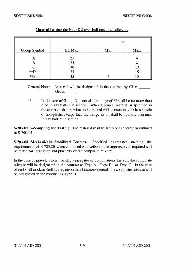
STATE AID 2004 STATE AID 2004
STATE AID 2004 STATE AID 20047-30
SECTION S-703 SECTION S-703
Material Passing the No. 40 Sieve shall meet the following:
PI
Group Symbol LL Max. Min. Max.
A B C**D**E
2525303535 6
68101515
General Note: Material will be designated in the contract by Class ,Group .
** In the case of Group D material, the range of PI shall be no more thannine in any half-mile section. When Group E material is specified inthe contract, that portion to be treated with cement may be less plasticor non-plastic except that the range in PI shall be no more than ninein any half-mile section.
S-703.07.3--Sampling and Testing. The material shall be sampled and tested as outlinedin S-700.03.
S-703.08--Mechanically Stabilized Courses. Specified aggregates meeting therequirements of S-703.20 when combined with soils or other aggregates as required willbe tested for gradation and plasticity of the composite mixture.
In the case of gravel, stone, or slag aggregates or combinations thereof, the compositemixture will be designated in the contract as Type A, Type B, or Type C. In the caseof reef shell or clam shell aggregates or combinations thereof, the composite mixture willbe designated in the contract as Type D.
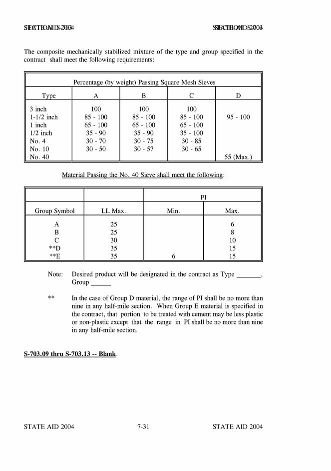
STATE AID 2004 STATE AID 2004
STATE AID 2004 STATE AID 20047-31
SECTION S-703 SECTION S-703
The composite mechanically stabilized mixture of the type and group specified in thecontract shall meet the following requirements:
Percentage (by weight) Passing Square Mesh Sieves
Type A B C D
3 inch1-1/2 inch1 inch1/2 inchNo. 4No. 10No. 40
10085 - 10065 - 10035 - 9030 - 7030 - 50
10085 - 10065 - 10035 - 9030 - 7530 - 57
10085 - 10065 - 10035 - 10030 - 8530 - 65
95 - 100
55 (Max.)
Material Passing the No. 40 Sieve shall meet the following:
PI
Group Symbol LL Max. Min. Max.
A B C**D**E
2525303535 6
68101515
Note: Desired product will be designated in the contract as Type ,Group
** In the case of Group D material, the range of PI shall be no more thannine in any half-mile section. When Group E material is specified inthe contract, that portion to be treated with cement may be less plasticor non-plastic except that the range in PI shall be no more than ninein any half-mile section.
S-703.09 thru S-703.13 -- Blank.
STATE AID 2004 STATE AID 2004
STATE AID 2004 STATE AID 20047-32
SECTION S-703 SECTION S-703
S-703.14--Aggregate for Bituminous Surface Treatments.
S-703.14.1--General Requirements. Aggregate for bituminous surface treatments andliquid seals shall consist of crushed stone, crushed slag, gravel, or expanded clay asspecified in the contract.
Only one kind and type of aggregate shall be used on a single course unless otherwiseauthorized in writing by the Engineer.
S-703.14.2--Detail Requirements.
S-703.14.2.1--Gradation. Aggregates shall conform to the gradation requirementscontained in the following table:
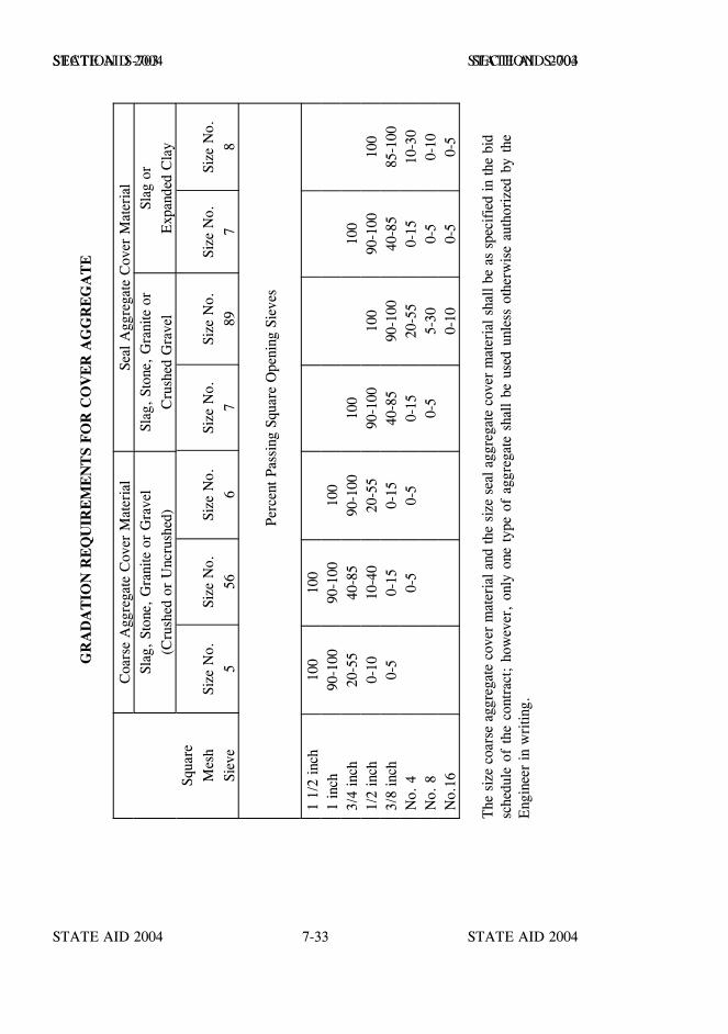
STATE AID 2004 STATE AID 2004
STATE AID 2004 STATE AID 20047-33
SECTION S-703 SECTION S-703
GR
AD
AT
ION
RE
QU
IRE
ME
NT
S F
OR
CO
VE
R A
GG
RE
GA
TE
Coa
rse
Agg
rega
te C
over
Mat
eria
lSe
al A
ggre
gate
Cov
er M
ater
ial
Slag
, St
one,
Gra
nite
or
Gra
vel
(Cru
shed
or
Unc
rush
ed)
Slag
, St
one,
Gra
nite
or
Cru
shed
Gra
vel
Slag
or
Exp
ande
d C
lay
Squa
reM
esh
Siev
eSi
ze N
o.5
Size
No.
56Si
ze N
o.6
Size
No.
7Si
ze N
o.89
Size
No.
7Si
ze N
o.8
Perc
ent P
assi
ng S
quar
e O
peni
ng S
ieve
s
1 1/
2 in
ch10
010
01
inch
90-1
0090
-100
100
3/4
inch
20-5
540
-85
90-1
0010
010
01/
2 in
ch0-
1010
-40
20-5
590
-100
100
90-1
0010
03/
8 in
ch0-
50-
150-
1540
-85
90-1
0040
-85
85-1
00N
o. 4
0-5
0-5
0-15
20-5
50-
1510
-30
No.
80-
55-
300-
50-
10N
o.16
0-10
0-5
0-5
The
siz
e co
arse
agg
rega
te c
over
mat
eria
l and
the
size
sea
l agg
rega
te c
over
mat
eria
l sha
ll be
as
spec
ifie
d in
the
bid
sche
dule
of
the
cont
ract
; ho
wev
er,
only
one
typ
e of
agg
rega
te s
hall
be u
sed
unle
ss o
ther
wis
e au
thor
ized
by
the
Eng
inee
r in
wri
ting.
STATE AID 2004 STATE AID 2004
STATE AID 2004 STATE AID 20047-34
SECTION S-703 SECTION S-703
S-703.14.2.2--All Materials. The quantity of deleterious substances shall not exceed thelimits set out in S-703.03.2.1 for general use.
When subjected to five cycles of Soundness Test for Coarse Aggregate by use ofmagnesium sulfate, the weighted percentage of loss shall not be more than 15.
The percentage of wear, when tested for abrasion in accordance with AASHTODesignation: T 96, shall not be more than 40%.
S-703.14.2.3--Crushed Stone. Crushed stone shall consist of clean, tough, durable,uncoated fragments free from an excess of soft or disintegrated pieces.
S-703.14.2.4--Crushed Slag. Crushed slag shall be air-cooled slag consisting of angularfragments, reasonably uniform in density and quality, and reasonably free of dirt or otherobjectionable matter. Crushed slag shall have a dry-rodded weight of 70 to 90 pounds percubic foot when tested in accordance with AASHTO Designation: T 19 and shall notcontain more than 10 percent by weight of glassy particles. The maximum unit weightis waived for chromium slag.
S-703.14.2.5--Crushed Gravel. Crushed gravel shall be composed of clean, tough,durable particles of gravel, free from excess dirt or other objectionable matter. At least85% by weight of the particles retained on the No. 10 sieve shall have one or morefractured faces.
S-703.14.2.6--Uncrushed Gravel. Uncrushed gravel shall be composed of clean,tough, durable particles free from excess vegetable or other objectionable matter. It shallmeet the requirements specified above for all materials as to deleterious substances.
S-703.14.2.7--Expanded Clay. Expanded clay aggregate shall be the product of a plantapproved by the Engineer. It shall conform to the gradation requirements in the precedingtable and to requirements of ASTM Designation: C 330, with the following exception:The loss by abrasion shall not be more than 40% when subjected to the Los AngelesAbrasion Test, AASHTO Designation: T 96.
When used for sealing joints, the soundness and abrasion requirements will be waived.
S-703.15--Blank.
S-703.16--Mineral Filler. Mineral filler shall consist of shell dust, limestone dust,portland cement, or other calcareous type materials having a high affinity for asphalt.The source of the material shall be approved by the Engineer.
STATE AID 2004 STATE AID 2004
STATE AID 2004 STATE AID 20047-35
SECTION S-703 SECTION S-703
Mineral filler shall meet the following gradation requirements:
Passing the No. 30 sieve, % ................................. 100Passing the No. 50 sieve, not less than, % ................ 95Passing the No. 200 sieve, not less than, % ................ 65
S-703.17--Blank.
S-703.18--Mortar Sand. Sand for mortar shall consist of hard, strong, durable,uncoated mineral or rock particles, free of injurious amounts of organic or otherdeleterious substances. It shall not contain, by weight, more than three percent clay orinorganic silt or combination thereof.
Mortar sand shall be uniformly graded from coarse to fine within the following limits:
Sieve Size % Passing No. 4 100 No. 8 97-100 No. 50 8-40 No. 100 0-10 No. 200 0-5
Mortar sand shall meet other requirements of AASHTO Designation: M 45.
S-703.19–Blank.
S-703.20--Aggregate for Stabilizer.
S-703.20.1--General Requirements. The material for stabilizer aggregate shall meet therequirements hereinafter specified for each type.
The gradation limits shown below are the maxima and minima for all cases, and a closercontrol appropriate to the job materials will be required for the specific project. Each typeof aggregate shall be uniformly graded from coarse to fine. Skip-graded material will notbe acceptable.
STATE AID 2004 STATE AID 2004
STATE AID 2004 STATE AID 20047-36
SECTION S-703 SECTION S-703
S-703.20.2--Detail Requirements.
S-703.20.2.1--Gravel, Stone, or Slag Coarse Stabilizer. Gravel or stone shall becomposed of hard, tough, durable particles reasonably free of injurious or deleterioussubstances. The percentage of wear, when tested in accordance with AASHTODesignation: T 96, shall not exceed 50%.Slag shall be air-cooled slag, consisting ofangular fragments, reasonably uniform in density and quality, and reasonably free of dirtor other objectionable matter. The weight shall be not less than 70 pounds per cubic foot.The percentage of wear, when tested in accordance with AASHTO Designation: T 96,shall not exceed 50%.
S-703.20.2.2--Shell. Shell shall consist of durable, washed particles of slaked clam orreef shell or combination thereof. The shell shall be free of objectionable matter such assticks, mud, clay lumps, or other deleterious matter. Not more than four percent byweight of clay and sand will be permitted and such material shall be dispersed throughoutthe mass.
Clam shell shall consist of washed dead clam shell. Reef shell shall consist of washeddead oyster shell and not contain cannery or live shell.
S-703.20.2.3--Medium and Fine Stabilizer. Medium aggregate stabilizer and fineaggregate stabilizer shall consist of sand, stone, shell, and/or slag screenings.
Slag screenings, sand, or stone shall be composed of hard, durable particles reasonablyfree of injurious amounts of soft or flaky particles, dust lumps, organic, or otherdeleterious substances. Shell shall comply with the requirements set out S-703.20.2.2.
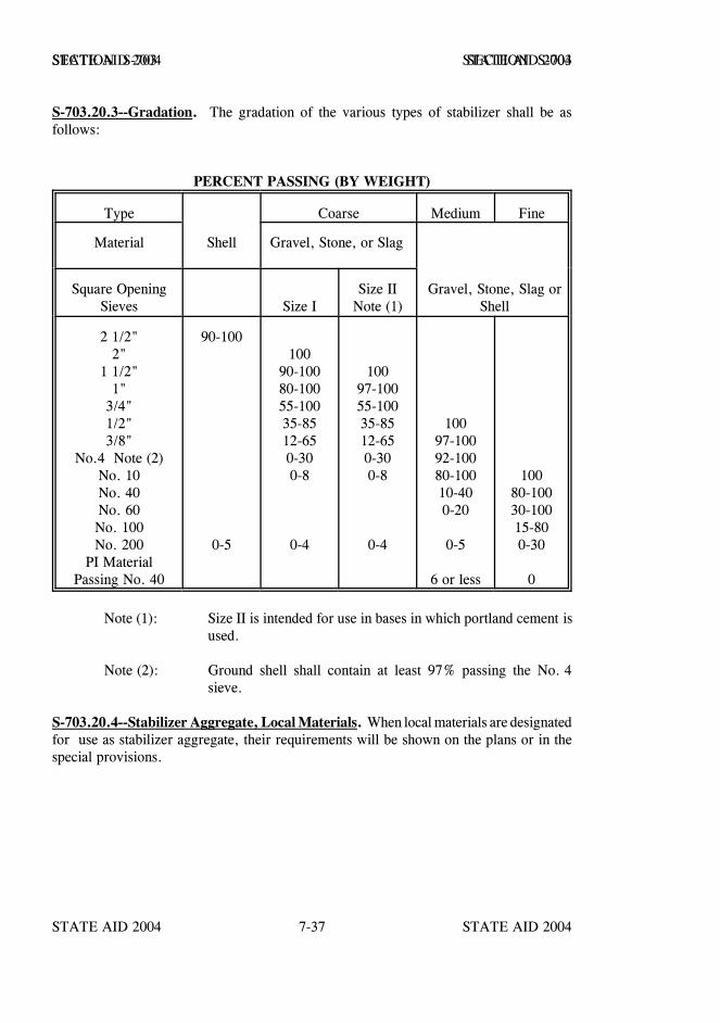
STATE AID 2004 STATE AID 2004
STATE AID 2004 STATE AID 20047-37
SECTION S-703 SECTION S-703
S-703.20.3--Gradation. The gradation of the various types of stabilizer shall be asfollows:
PERCENT PASSING (BY WEIGHT)
Type Coarse Medium Fine
Material Shell Gravel, Stone, or Slag
Square OpeningSieves Size I
Size IINote (1)
Gravel, Stone, Slag orShell
2 1/2"2"
1 1/2"1"
3/4"1/2"3/8"
No.4 Note (2)No. 10No. 40No. 60No. 100No. 200
PI MaterialPassing No. 40
90-100
0-5
10090-10080-10055-10035-8512-650-300-8
0-4
10097-10055-10035-8512-650-300-8
0-4
10097-10092-10080-10010-400-20
0-5
6 or less
10080-10030-10015-800-30
0
Note (1): Size II is intended for use in bases in which portland cement isused.
Note (2): Ground shell shall contain at least 97% passing the No. 4sieve.
S-703.20.4--Stabilizer Aggregate, Local Materials. When local materials are designatedfor use as stabilizer aggregate, their requirements will be shown on the plans or in thespecial provisions.

STATE AID 2004 STATE AID 2004
STATE AID 2004 STATE AID 20047-38
SECTION S-703 SECTION S-703
S-703.21--Borrow Excavation. Borrow excavation shall be composed of a natural ormanufactured mixture of sand, silt, and clay or combinations of sand, silt, clay, gravelor stone. The material shall have satisfactory cementing qualities, shall be reasonably freeof vegetable matter or other deleterious substances that cannot be classed as serviceable,and shall be such that when properly compacted will form a dense mass. When rock orstone is used in the embankment, it shall be so graded and manipulated that theembankment will contain no appreciable interstices.
Borrow excavation from outside the right-of-way is divided into classes, each classconforming to the requirements set-out in the following table:
Class 1 2 3 4 5 6 7 8 9 10
Percent Passing No.200 Sieve (Max.) 25 35 10 35 35 35 100 100 100 100
Fraction PassingNo. 40 Sieve -Liquid Limit (Max.) -- 40 -- 45 40 45 40 55 40 55
Plasticity Index,(Max.) 6 10 np 10 20 25 10 10 20 --
The Class of material will be specified in the contract.
When the contract contains a numerical designation after the class number, it shall beunderstood to indicate the requirement that the material shall have a minimum PI of notless than that indicated by the numerical designation. For example, Class 9-6 requiresClass 9 material having a minimum PI of 6; or a Class 9-10 requires Class 9 materialhaving a minimum PI of 10, etc.
When a minimum PI is specified, the maximum plasticity index and the maximum liquidlimit, as indicated in the table, will be raised the numerical designation for minimum PI,except that in the case of Class 8 and Class 10 the maximum liquid limit shall remain asindicated in the table above.
For the design soil portion of the embankment all of the material shall pass a 3 inch sieve.Individual contracts may further restrict the maximum size of material in the topportion of the design soil.
STATE AID 2004 STATE AID 2004
STATE AID 2004 STATE AID 20047-39
SECTION S-704 - AGGREGATE FOR DRAINAGE
S-704.01--Permeable Material. Permeable material for use in backfilling trenches,under, around, and over underdrains and permeable material for blankets or othersubdrainage purposes shall consist of hard, durable, clean sand, gravel, crushed stone,or crushed slag, and shall be free from organic material, clay balls, or other deleterioussubstances. These materials shall be as designated by Type as set out below.
S-704.02--Type A. Filter Material. Type A filter material shall meet the requirementsfor Size 7 seal cover aggregate, or Size 7, 57, or 67 coarse aggregate for portland cementconcrete, or Size II gravel coarse stabilizer as set out in S-703. The crushing requirementfor gravel seal cover aggregate is not applicable.
S-704.03--Type B. Filter Material. Type B filter material shall be concrete sandconforming to the requirements of S-703.02, except that the requirements for finenessmodulus (FM) will not apply.
S-704.04--Type C. Filter Material. Type C filter material shall consist of sand, stone,and/or slag screenings composed of hard, durable particles reasonably free of injuriousamounts of soft or flaky particles, dust, lumps, organic, or other deleterious substances.
The gradation of the material shall be as follows:
Sieve Size Percent Passing
1/2"No. 4No. 16No. 50No. 100
10080-10037-805-300-10
S-704.05--Type D. Impervious Material. Type D impervious material shall consist ofnatural soil, soil aggregates, or a blend of natural soil and aggregates. The material shallbe reasonably free of sticks, roots and other objectionable matter, shall be classified asGroup A-6 or A-7, and shall conform with the following:
Percent Passing No. 10 Sieve 80-100Percent Passing No. 200 Sieve 36 (Min.)Liquid Limit 50 (Max.)Plasticity Index 12-25pH 4.5-8.0
STATE AID 2004 STATE AID 2004
STATE AID 2004 STATE AID 20047-40
SECTION S-705 - STONE BLANKET PROTECTION ANDFILTER BLANKET MATERIALS
S-705.01--Stone Blanket Protection. In addition to meeting the quality requirements ofAASHTO Designation: M 80, stone blanket protection shall be in accordance withAASHTO Designation: M 43, Size No. 357.
S-705.02--Stone Filter Blanket. In addition to meeting the quality requirements ofAASHTO Designation: M 80, Class E, filter blanket material shall conform to thegradation requirements of AASHTO Designation: M 43, Size No. 467.
S-705.03--Sand Filter Blanket. The sand filter blanket shall conform to the requirementsof S-703.02 for concrete sand.
S-705.04--Stone Riprap. Aggregate for loose riprap, stone riprap for foundationprotection, or that to be grouted shall consist of field stone, broken concrete, or rough,unhewn quarry stone as nearly rectangular in section as is practicable. The stone shall bedense, free of clay or shale seams, resistant to the action of air and water, and suitable inall other respects for the purpose intended. Quality requirements for rock to be furnishedunder these specifications will be checked or tested as determined by the MDOTMaterials Engineer prior to use and subsequently if deemed appropriate.
Stones for riprap, of the size specified, shall meet the requirements for size by weightas specified in the following table:
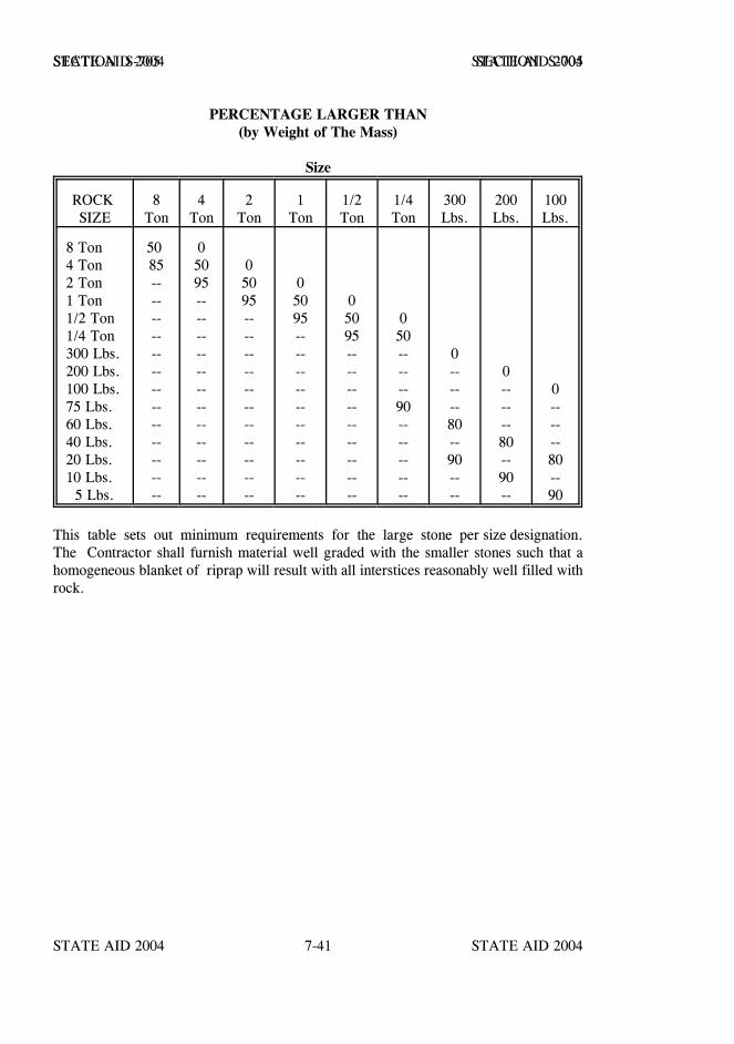
STATE AID 2004 STATE AID 2004
STATE AID 2004 STATE AID 20047-41
SECTION S-705 SECTION S-705
PERCENTAGE LARGER THAN(by Weight of The Mass)
Size
ROCK SIZE
8Ton
4Ton
2Ton
1Ton
1/2Ton
1/4Ton
300Lbs.
200Lbs.
100Lbs.
8 Ton4 Ton2 Ton1 Ton1/2 Ton1/4 Ton300 Lbs.200 Lbs.100 Lbs.75 Lbs.60 Lbs.40 Lbs.20 Lbs.10 Lbs. 5 Lbs.
50 85--------------------------
05095------------------------
05095----------------------
05095--------------------
05095------------------
050------90----------
0------80--90----
0------80--90--
0------80--90
This table sets out minimum requirements for the large stone per size designation.The Contractor shall furnish material well graded with the smaller stones such that ahomogeneous blanket of riprap will result with all interstices reasonably well filled withrock.
STATE AID 2004 STATE AID 2004
STATE AID 2004 STATE AID 20047-42
SECTION S-706 - MASONRY UNITS
S-706.01--Brick.
S-706.01.1--General. Brick shall have a fine-grained, uniform, and dense structure,and be free of lumps of lime, laminations, cracks, checks, soluble salts, or other defectswhich may in any way impair the strength, durability, appearance or usefulness of thebrick for the purpose intended. Bricks shall emit a clear, metallic ring when struck witha hammer.
S-706.01.2–Building Brick. Unless otherwise stipulated, building brick shall conformto AASHTO Designation: M 114, Grade SW.
S-706.01.3---Sewer and Manhole Brick. Unless otherwise stipulated, brick for sewerand manholes shall conform to AASHTO Designation: M 91, Grade SM.
S-706.02--Concrete Brick. Concrete brick shall conform to ASTM Designation: C 55,Grade N, Type I.
S-706.03--Concrete Masonry Blocks. Concrete masonry blocks may be rectangular orsegmented and, when specified, shall have ends shaped to provide interlock at verticaljoints. The blocks shall conform to the requirements of ASTM Designation: C 139; or,for hollow blocks, to ASTM Designation: C 90, Grade N, Type I. Dimensions andtolerances shall be specified.
S-706.04--Right-of-Way Markers.
S-706.04.1--General. Right-of-way markers shall be constructed in conformity with thedetails shown on the plans and shall meet the requirements hereinafter set forth. Whenmore than 20% of the units in a lot is rejected, the entire lot will be rejected.
S-706.04.2--Manufacture.
S-706.04.2.1--Description. The exposed portion of the marker shall present a smooth,uniform surface, free of honeycomb, chips, or other defects. The shape, dimensions, andplacement of steel shall be in accordance with details shown on the plans. All letters,figures, or other markings shall be true to type and size shown on the plans, and shall belegible.
S-706.04.2.2--Materials. The materials used in the manufacture shall conform to thefollowing:
S-706.04.2.2.1--Cement. The cement used shall meet the requirements of S-701.
STATE AID 2004 STATE AID 2004
STATE AID 2004 STATE AID 20047-43
SECTION S-706 SECTION S-706
S-706.04.2.2.2--Aggregates. The aggregates used shall conform to therequirements of S-703.02 and S-703.03, except that the requirements for gradation willnot apply.
S-706.04.2.2.3--Reinforcing Steel. Reinforcing steel shall conform to the requirementsof S-711.01.
S-706.04.2.2.4--Proportions. The concrete shall have a minimum cement factor of1.25.
S-706.04.2.2.5--Strength Requirements. The strength of the right-of-way markers shallbe determined by the beam method. Under the beam method, a completed unit is loadedat the midpoint of an 18 inch span with three edge bearing; the unit shall develop astrength of not less than 12,000 pounds, total load. Two specimens will be tested foreach 200 units, or increment thereof; one to destruction and one to the ultimate load of12,000 pounds.
STATE AID 2004 STATE AID 2004
STATE AID 2004 STATE AID 20047-44
SECTION S-707 - JOINT MATERIALS
S-707.01--General. Joint fillers and seals for concrete bridges, concrete pavements orbase course, and culvert pipe shall meet the requirements indicated on the plans or in thespecial provisions, and shall conform to the following applicable subsections.
S-707.02--Joint Fillers.
S-707.02.1--Poured Joint Filler.
S-707.02.1.1--Asphalt Joint Material. Poured asphalt filler shall be blown asphalt,Grade AC-13, conforming to the requirements of S-702.12, Table I.
S-707.02.1.2--Polymerized Emulsified Asphalt Joint Material. Cold appliedpolymerized-emulsified asphalt joint material shall meet the following requirements whentested in accordance with AASHTO Designation: T 59 and as specified below:
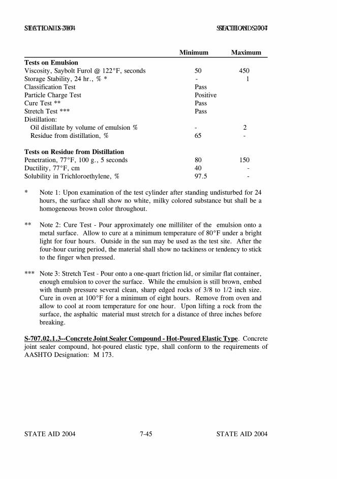
STATE AID 2004 STATE AID 2004
STATE AID 2004 STATE AID 20047-45
SECTION S-707 SECTION S-707
Minimum MaximumTests on EmulsionViscosity, Saybolt Furol @ 122°F, seconds 50 450Storage Stability, 24 hr., % * - 1Classification Test PassParticle Charge Test PositiveCure Test ** PassStretch Test *** PassDistillation: Oil distillate by volume of emulsion % - 2 Residue from distillation, % 65 -
Tests on Residue from DistillationPenetration, 77°F, 100 g., 5 seconds 80 150Ductility, 77°F, cm 40 -Solubility in Trichloroethylene, % 97.5 -
* Note 1: Upon examination of the test cylinder after standing undisturbed for 24hours, the surface shall show no white, milky colored substance but shall be ahomogeneous brown color throughout.
** Note 2: Cure Test - Pour approximately one milliliter of the emulsion onto ametal surface. Allow to cure at a minimum temperature of 80°F under a brightlight for four hours. Outside in the sun may be used as the test site. After thefour-hour curing period, the material shall show no tackiness or tendency to stickto the finger when pressed.
*** Note 3: Stretch Test - Pour onto a one-quart friction lid, or similar flat container,enough emulsion to cover the surface. While the emulsion is still brown, embedwith thumb pressure several clean, sharp edged rocks of 3/8 to 1/2 inch size.Cure in oven at 100°F for a minimum of eight hours. Remove from oven andallow to cool at room temperature for one hour. Upon lifting a rock from thesurface, the asphaltic material must stretch for a distance of three inches beforebreaking.
S-707.02.1.3--Concrete Joint Sealer Compound - Hot-Poured Elastic Type. Concretejoint sealer compound, hot-poured elastic type, shall conform to the requirements ofAASHTO Designation: M 173.

STATE AID 2004 STATE AID 2004
STATE AID 2004 STATE AID 20047-46
SECTION S-707 SECTION S-707
S-707.02.1.4--Silicone Sealant. The silicone sealant must have been approved for listingin the MDOT’s "Approved Sources of Materials" prior to its use. The silicone sealantshall be a single component low modulus non-acetic acid cure sealant which does notrequire a primer for bond to concrete. Unless specifically designated otherwise, siliconesealant shall be either the standard non-sag type or the self-leveling type meeting thefollowing requirements:
PHYSICAL REQUIREMENTS
Standard Self- Non-Sag Leveling
Property Type TypeShore A Durometer Hardness, 10 - 25 Maximum7-day cure @ 73.4 ±3.6°F & 45% to 55% R.H.,ASTM Designation: D 2240
Elongation, 7-day cure @ 73.4 ±3.6°F & 500% 500%45% to 55% R.H., ASTM Designation: D 412,Method A, Die C, minimum
Tensile Stress @ 150% Elongation, 20 - 45 psi 10 - 30 psi7-day cure @ 73.4 ±3.6°F & 45% to 55% R.H.,ASTM Designation: D 412, Method A, Die C
Flow/Sag, ASTM Designation: C 639, maximum 0.3 inch Self-Leveling
Tack-Free Time, 73.4 ±3.6°F & 45% to 55% R.H.,90 minutes 180 minutesASTM Designation: C 679, maximum
Shelf Life from Date of Manufacture, minimum 6 months 6 months
The manufacturer of the joint material shall furnish certified test results of each lot ofmaterial furnished to each project. Each lot of the sealant shall be delivered in containersplainly marked with manufacturer's name or trade mark, lot number and date ofmanufacture.
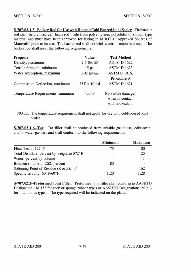
STATE AID 2004 STATE AID 2004
STATE AID 2004 STATE AID 20047-47
SECTION S-707 SECTION S-707
S-707.02.1.5--Backer Rod for Use with Hot and Cold Poured Joint Sealer. The backerrod shall be a closed-cell foam rod made from polyethylene, polyolefin or similar typematerial and must have been approved for listing in MDOT's "Approved Sources ofMaterials" prior to its use. The backer rod shall not wick water or retain moisture. Thebacker rod shall meet the following requirements:
Property Value Test MethodDensity, maximum 2.5 lbs/ft3 ASTM D 1622Tensile Strength, minimum 15 psi ASTM D 1623Water Absorption, maximum 0.02 g/cm3 ASTM C 1016,
Procedure ACompression Deflection, maximum 25%at 10 psi ASTM D 1621
Temperature Requirements, minimum 450°F No visible damage, when in contact with hot sealant
NOTE: The temperature requirement shall not apply for use with cold-poured jointsealer.
S-707.02.1.6--Tar. Tar filler shall be produced from suitable gas-house, coke-oven,and/or water-gas tars and shall conform to the following requirements:
Minimum Maximum
Float Test at 122°F 75 100Total Distillate, percent by weight to 572°F - 25Water, percent by volume 1Bitumen soluble in CS2, percent 80 -Softening Point of Residue (R & B), °F 162Specific Gravity, 60°F/60°F 1.20 1.28
S-707.02.2--Preformed Joint Filler. Preformed joint filler shall conform to AASHTODesignation: M 153 for cork or sponge rubber types or AASHTO Designation: M 213for bituminous types. The type required will be indicated on the plans.
STATE AID 2004 STATE AID 2004
STATE AID 2004 STATE AID 20047-48
SECTION S-707 SECTION S-707
S-707.02.3--Wood. Wood board joint filler shall be redwood, cypress, yellow pine,white pine, fir, longleaf pine, Tupelo gum, or other lumber classed as softwood, and shallconform to the following requirements:
Boards shall be free of knots, except that small pin knots 1/4 inch maximum diameterwill be permitted. Boards containing occasional knots of larger size may be used,provided the knots are removed and the holes either filled with properly sized plugs ofthe same type wood or covered with approved thin metal attached to the board.Occasional medium surface checks not to exceed 1/32 inch width and 10 inch lengthwill be permitted, provided the board is free of defects that will impair its usefulnessfor the purpose intended.Dimensions shall be as shown on the plans, and tolerances ofplus or minus 1/16 inch thickness and plus or minus 1/8 inch width will be permitted.For slip-form paving a tolerance of minus 1/4 inch on each end in length will bepermitted.The oven-dry weight shall not exceed 38 pounds per cubic foot, and the loadrequired to compress the material in an oven-dry condition to 50% of its thicknessbefore test shall not be more than 2500 psi.
A sample shall be submitted for each shipment of 1000 linear feet or less. Each sampleshall consist of a representative section at least 36 inches long and the full depth of thejoint. Testing shall be in accordance with AASHTO Designation: T 42, as applicable.
The joint filler shall be a one-piece board or a lamination of like species of the requiredthickness, depth and lane width length without joints or splicing except that milled shopfinger end joints are permissible.
S-707.02.4--Preformed Joint Insert Material for Concrete Paving. Preformed jointinsert material shall be composed of 1/4 x 2-inch preformed, non-extruding fiber board.The fiber shall be impregnated with asphalt or other approved binding material. The fiberboard shall be of such character as not to be deformed or broken by twisting, bending, orother ordinary handling when exposed to atmospheric conditions. Pieces of the joint fillerthat have been damaged shall be rejected. This material is for use in longitudinal joints.

STATE AID 2004 STATE AID 2004
STATE AID 2004 STATE AID 20047-49
SECTION S-707 SECTION S-707
S-707.02.5--Preformed Elastomeric Compressive Joint Seals for Concrete. Thepreformed elastic joint shall be a polychloroprene joint sealer of the size and shape shownon the plans, bonded to the concrete with a lubricant adhesive and shall conform toAASHTO Designation: M 220.
The lubricant adhesive shall be in accordance with the recommendation of themanufacturer of the joint seals.
The Contractor shall submit the manufacturer's certified test results for each lot of jointseals.
S-707.03--Blank.
S-707.04--Rubber Type Gaskets for Joining Conduit. Rubber gaskets for pipe jointsand revisions in design of pipe for installation of the gaskets shall conform to therequirements of AASHTO Designation: M 315. The Contractor shall submit themanufacturer's certified test results for each consignment of material.
S-707.05--Bituminous Plastic Sealer for Joining Conduit. Bituminous plastic sealershall be composed of steam-refined petroleum asphalt or refined coal tar which has beendissolved in a suitable solvent and stiffened with an inert mineral filler.
The sealer shall be a smooth uniform mixture, not thickened or livered; it shall show noseparation which cannot be easily overcome by stirring. The material shall be of suchconsistency and properties that it can be readily applied with a trowel, a putty knife, ora caulking gun without pulling or drawing. The material, when applied to pipe surfaces,shall exhibit good adhesive and cohesive properties and shall have only slight shrinkageafter curing. The material shall be capable of being exposed to below freezingtemperatures without incurring damage. When applied in a layer of 1/16 inch to 1/8 inchthick on a tinned metal panel and cured at room temperature for 24 hours, the bituminousplastic sealer shall set to a tough plastic coating, free of blisters. Additional requirementsare:
Minimum Maximum
Grease cone penetration, unworked, 150 grams,25°C, 5 sec., ASTM Designation: D 217, mm/10 175 250
Weight, pounds per gallon 9.75 -Non-volatile, 19 grams, 105°C - 110°C, 24 hrs., % 75 -Ash, by ignition, % 25 55

STATE AID 2004 STATE AID 2004
STATE AID 2004 STATE AID 20047-50
SECTION S-707 SECTION S-707
S-707.06--Flexible Plastic Gasket for Joining Conduit. Gasket joint seals shall beproduced from blends of refined hydrocarbon resins and plasticizing compoundsreinforced with inert mineral filler and shall contain no solvents. The gasket joint sealershall not depend on oxidizing, evaporating, or chemical action for its adhesive or cohesivestrength and shall be supplied in extruded rope form of suitable cross-section and of suchsize as to fill the joint space when the pipes are laid. The gasket joint sealer shall beprotected by a suitable removable two-piece wrapper. The two-piece wrapper shall be sodesigned that one-half may be removed longitudinally without disturbing the other half.
The material shall be obtained from approved sources and the approval will be basedon results of testing as required herein.
The Engineer may require the performance test described in AASHTO Designation:M 198.
Flexible plastic gasket shall also meet the following requirements:
Minimum Maximum Test Method
CompositionBitumen / Petroleum Plastic Content 50 70 ASTM D 4Ash-Inert Mineral Matter 30 50 AASHTO T 111Volatile Matter -- 2.0 ASTM D 6
PropertySpecific Gravity at 77°F 1.20 1.35 ASTM D 71*Ductility at 77°F (cm) 5.0 -- ASTM D 113*Softening Point 320°F -- ASTM D 36*Penetration 77°F, 150 g, 5 sec. 50 120 ASTM D 217
* Due to the nature of the material, each sample to be tested must be manuallykneaded, in lieu of heating and pouring, into the testing containers.
The Contractor shall furnish the Engineer three copies of the manufacturer's certificate,stating that the flexible plastic gasket meets all the requirements of these specifications andhas the properties and characteristics herein specified.
STATE AID 2004 STATE AID 2004
STATE AID 2004 STATE AID 20047-51
SECTION S-707 SECTION S-707
S-707.07--Neoprene Expansion Joints.
S-707.07.1--General. Neoprene expansion joints shall consist of an integrally moldedunit of neoprene and bonded metal components or neoprene extrusions bonded to steelextrusions so arranged as to provide for the expansion and contraction movements of thebridge deck.
S-707.07.2--Material Requirements. Materials used in the manufacture of the expansionjoints shall meet the following requirements:
Neoprene shall meet the requirements of AASHTO Designation: M 220.
Steel plates bonded in the joints and steel extrusions shall conform to therequirements of ASTM Designation: A 36.
Aluminum plates used in the manufacture of the expansion joints shall conformto the requirements of ASTM Designation: B 209, Alloy 6061-T6.
Anchor bolts or studs shall be of a weldable alloy if arc welding is used, andshall conform to the strength requirements of ASTM Designation: A 307, GradeA Low Carbon Steel Fasteners.
S-707.07.3--Certification of Materials. The Contractor shall furnish the Engineer threecopies of the manufacturer's certificate, stating that the expansion joint and eachcomponent material meets all the requirements of these specifications and have theproperties and characteristics herein specified.
STATE AID 2004 STATE AID 2004
STATE AID 2004 STATE AID 20047-52
SECTION S-708 - NON-METAL STRUCTURES AND CATTLEPASSES
S-708.01--General. The structures covered in these specifications are for use as pipeculverts, precast box culverts, cattlepasses, sidedrains, sewers, underdrains, anddownspouts.
S-708.02--Concrete Pipe. Unless otherwise specified, pipe and tile shall conform to therequirements hereinafter set forth. When more than 20% of the pipe in a lot is rejected,the entire lot of pipe will be rejected.
When elliptical reinforcing is used, lift holes shall be cast in the top and "Top" or"Bottom" shall be clearly inscribed or stenciled on the inside of the pipe to indicate theproper position when laid. When it is found that the position for laying is not marked,or is marked improperly, the entire lot of such pipe will be rejected.
When rubber gasket joints are permitted or specified, the pipe joints shall be soconstructed as to accommodate this type of jointing.
S-708.02.1--Materials for Use in Concrete Pipe.
S-708.02.1.1--Cement. Portland Cement Types I, II or III, or blended hydraulic cement,shall conform to the requirements set out in S-701.
S-708.02.1.2--Fly Ash. Fly ash conforming to the requirements of S- 714.05 may beused to replace portland cement on a one to one replacement rate but not to exceed 20percent by weight of the portland cement.
S-708.02.1.3--Fine Aggregate. Fine aggregate shall consist of natural sand and shallconform to the requirements set out in S-703.02, except that the requirements forgradation are not applicable.
S-708.02.1.4--Coarse Aggregate. Coarse aggregate shall consist of gravel or crushedlimestone conforming to the requirements of S-703.03, except that the requirements forgradation are not applicable. Concrete pipe made with crushed limestone coarse aggregatewill not be permitted for use on a project with a soil pH lower than 4.5.
S-708.02.1.5--Water. The water shall conform to the requirements set out in S-714.01.2.
S-708.02.1.6--Reinforcement. Reinforcement shall consist of wire conforming to theapplicable requirements of S-711.02.
STATE AID 2004 STATE AID 2004
STATE AID 2004 STATE AID 20047-53
SECTION S-708 SECTION S-708
S-708.02.2--Manufacture. General. Circular pipe of 54-inch diameter and smaller shallbe machine made. Other pipe may be either machine made or wet cast.
All sizes of concrete pipe may be furnished with either bell and spigot or tongue andgroove, provided that the minimum thickness of concrete on the groove end is at least 1¼inches. This measurement for thickness will be made at a point 3/8 inch from the outerend of the groove.
When no particular length is specified, the pipe shall be manufactured in standard lengthsof at least 2 1/2 feet and not more than eight feet.
The pipe shall be constructed in such a manner and of such design that the joint will meetthe same requirements for strength stipulated for the pipe.
S-708.02.3--Exceptions to AASHTO Standard Specifications.
S-708.02.3.1--Liquid Membrane Curing Compound. Liquid membrane curingcompound will not be permitted.
S-708.02.3.2--Marking. Required markings shall be placed on the inside wall of thepipe. Machine made pipe shall be inscribed on the outside of the pipe and stenciled onthe inside, other pipe may be stenciled. The specification designation for reinforced pipemay be excluded from the required markings.
S-708.02.3.3--Basis of Acceptance. All pipe will be tested under Option I, three-edgebearing test, or Option II, cylinder test, as set forth in MDOT SOP.
Pipe having a diameter of 30 inches or less will be tested under Option I.
Pipe larger than 30 inches in diameter will be tested under Option I or II. The pipeproducer shall advise the MDOT Testing Engineer in writing of the option under whichthe pipe will be tested. The option chosen will remain in effect until rescinded in writing.
Flared end sections and cattlepasses will be tested under Option II unless otherwiseauthorized by the MDOT Testing Engineer.
The specified D-load and compressive strength shall be considered as minimum andallowable failures will not apply.
Normally, neither the absorption test nor the ultimate load will be required.
STATE AID 2004 STATE AID 2004
STATE AID 2004 STATE AID 20047-54
SECTION S-708 SECTION S-708
S-708.02.3.4--Rejection. All pipe shall be subject to rejection for nonconformance to thespecifications. Individual sections of pipe may be rejected for one or more of thefollowing:
Visible fractures or cracks, except for a single end crack that does not exceedthe depth of the joint.
Defects that indicate imperfect proportioning, mixing, and molding.
Surface defects indicating honey-combed or open texture.
Damaged or cracked ends which would prevent a satisfactory joint.
Defects indicating incorrect positioning of reinforcing steel.
S-708.02.3.5--Repairs. Repairs will not be permitted in the barrel of the pipe. Repairsmay be made on the ends, tongue and groove or bell and spigot, with an approvedcommercial concrete patching compound used according to manufacturer'srecommendations and properly cured.
S-708.02.3.6--Tongue and Groove. The thickness of the tongue shall not vary more than1/4 inch or five percent of the wall thickness, whichever is greater, when measured at theouter edge. The thickness of the groove shall not vary more than 1/4 inch or five percentof the wall thickness, whichever is greater, when measured at a point 3/8 inch from theouter end of the groove. The depth of the groove shall not vary more than 1/4 inch fromthe length of the tongue.
S-708.02.3.7--Lift Holes. Lift holes may be formed, punched, or drilled in plasticconcrete. Lift holes may be placed in cured pipe only by drilling with a diamondcore-drill bit.
S-708.02.4--Nonreinforced Concrete Pipe. In addition to the applicable requirementsof S-708.02, nonreinforced concrete pipe shall meet the requirements of AASHTODesignation: M 86 for the class specified. Testing shall be in accordance with AASHTODesignation: T 280.
S-708.02.5--Reinforced Concrete Pipe. All reinforced concrete pipe except Class V pipewith diameters of 54 inches and larger shall meet the requirements of AASHTODesignation: M 170 as modified by S-708.02.
STATE AID 2004 STATE AID 2004
STATE AID 2004 STATE AID 20047-55
SECTION S-708 SECTION S-708
Class V pipe with diameters of 54 inches and larger shall meet the requirements ofAASHTO Designation: M 170 or M 242 as modified by S-708.02 and herein.
Circular reinforced concrete pipe with S-stirrup reinforcement shall be inaccordance with Figure 1 and the following requirements.
The wall thickness, amount of circular reinforcement, S-stirrup system andconcrete strength shall comply with those set out in Table 1 herein. The spacingcenter to center of adjacent inner rings of circumferential reinforcement in a cageshall not exceed 4 inches for pipe up to and including pipe having a 4-inch wallthickness nor exceed 5 1/2 inches for 54 inch pipe and 6 inches for all other pipesizes.
Each line of S-stirrups shall have a continuous S shape extending longitudinallyfrom end to end of the pipe. They shall extend from the inner cage toward theouter surface of the pipe for a distance not less than the minimum amplitude.S-stirrups shall pass around and be in contact with each inside circumferentialmember of the inner cage. Each line of S-stirrups shall lie essentially in a planepassing through the longitudinal axis of the pipe.
Where more than one length of stirrup material is used per line, a lap around onecircumferential member of the inner cage shall be made. The ends of "S" shapedstirrups at splices shall include an outer bend. Not more than three lengths of Smaterial may be used in a line, and the minimum length of a section of S-stirrupsshall be 30 inches.
All designs in Table 1 are accepted designs with noted 0.01 inch crack andultimate D-load.
Additional Markings. After the capital letter "D" designating the D-load, showthe design wall thickness in inches expressed as a decimal. Pipe with "S"stirrups shall have the symbol S. Pipe requiring axis orientation without liftholes, i.e. stirrup pipe, quadrant reinforced pipe, shall have the center line of thecrown of the pipe marked inside and outside with the symbol TB. Pipe withquadrant steel shall be marked with the symbol Q. Pipe with deformed wirereinforcement required in the design shall have the symbol DF.
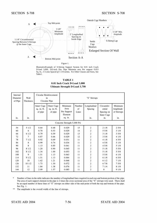
STATE AID 2004 STATE AID 2004
STATE AID 2004 STATE AID 20047-56
5 1/8" CircumferentialSpacing Between S-Stirrups
@ the Inner Cage.
5 5/8"MinimumAmplitude 2" Longitudinal
Spacing onInside Edge
Top Mid-point
Bottom Mid-point
Enlarged Section Of Wall
Section A-A
5 5/8" Min.Ampitude
Figure 1.
IllustrativeExample of S-Stirrup Support System for 0.01 inch CrackD-load 3,000, 102-inch Dia. Pipe Minimun area Per support 0.053Sq. In., 11 Lines Spaced @ 5 1/8 inches. For Other Classes and Sizes, SeeTable1.
SECTION S-708 SECTION S-708
TABLE 10.01 Inch Crack D-Load 3,000
Ultimate Strength D-Load 3,750
InternalDiameterof Pipe
WallThickness
Circular Reinforcementin
Circular Pipe"S" Stirrups
in. in.
Inner Cagesq. in./ft. of pipe
Outer Cagesq. in./ft. of pipe
MinimumArea
Per SupportElementsq. in.
Numberof
Lines.
LongitudinalSpacing
in.
Circumfer-ential
Spacing onInner Cage
in.
MinimumAmplitude..
of Stirrups
in.
Concrete Strength 5,000 Psi
5460667278849096102108114120126132144
5 1/26
6 1/27
7 1/288
8 1/28 1/2
99 1/210
10 1/21112
0.640.700.790.870.920.991.131.201.341.511.511.621.731.842.09
0.480.530.590.660.690.740.850.901.001.131.131.211.301.381.57
0.0290.0290.0290.0290.0310.0340.0410.0450.0530.0630.0640.0680.0720.0760.085
151413121111111111111111111111
222222222222222
2 1/85 5/83 1/83 5/84 1/84 5/84 5/85 1/85 1/85 5/86 1/86 1/26 7/87 1/48
2 5/83 1/83 5/84 1/84 5/85 1/85 1/85 5/85 5/86 1/86 5/87 1/87 5/88 1/89 1/8
* Number of lines in the table indicates the number of longitudinal lines required in each top and bottom portion of the pipe.The area of each support element in the pipe is 2 times the cross-sectional area of the “S” stirrups wire used. There shallbe an equal number of these lines of “S” stirrups on either side of the mid-point of both the top and bottom of the pipe.See Fig. 1.
** The amplitude is the overall width of the line of stirrups.

STATE AID 2004 STATE AID 2004
STATE AID 2004 STATE AID 20047-57
SECTION S-708 SECTION S-708
S-708.03--Concrete Cattlepasses. Concrete cattlepasses shall conform to the plans, theapplicable requirements of S-708.02, and the following: The requirements as tomanufacture, materials, and curing shall conform to the requirements of AASHTODesignation: M 170. The compressive strength of the concrete shall be at least 4000 psiat 28 days.
S-708.04--Reinforced Concrete Flared-End Section. Reinforced concrete flared-endsections shall conform to the plans, the applicable requirements of S-708.02 and thefollowing: The requirements as to manufacturer, materials, and curing shall be the sameas for the connecting pipe. The compressive strength of the concrete shall be at least 3000psi at 28 days.
S-708.05--Perforated Concrete Pipe. Perforated concrete pipe shall conform to therequirements of S-708.02.4 and AASHTO Designation: M 175.
S-708.06--Concrete Drain Tile. Standard drain tile or extra quality drain tile shallconform to the applicable requirements of AASHTO Designation: M 178.
S-708.07--Porous Concrete Pipe for Underdrains. Porous concrete pipe for underdrainsshall conform to the requirements of AASHTO Designation: M 176.
S-708.08 thru S-708.13--Blank.
S-708.14--Reinforced Concrete Arch Pipe. Reinforced concrete arch pipe shall meet therequirements of AASHTO Designation: M 206. Horizontal elliptical pipe may befurnished in lieu of arch pipe.
S-708.15--Reinforced Concrete Elliptical Culvert, Storm Drain, and Sewer Pipe. Thispipe shall conform to the requirements of AASHTO Designation: M 207.
S-708.16--Joints for Circular Concrete Sewer and Culvert Pipe, Using RubberGaskets. The joints shall conform to the requirements of AASHTO Designation: M 198.
STATE AID 2004 STATE AID 2004
STATE AID 2004 STATE AID 20047-58
SECTION S-708 SECTION S-708
S-708.17--Corrugated Plastic Pipe Culverts.
S-708.17.1--Corrugated Polyethylene Pipe Culverts. Corrugated polyethylene pipeshall conform to the requirements of AASHTO Designation: M 294, Type S.
The Contractor shall furnish to the Engineer three copies of the manufacturer's certifiedtest reports and certification covering each shipment of pipe stating the amount furnishedand that the pipe, fittings, couplings, etc. comply with the requirements of thespecifications. Certifications and certified test reports for compliance with thisspecification shall be performed by an approved third-party testing source.
S-708.17.2--Corrugated Poly (Vinyl Chloride) (PVC) Pipe Culverts. Corrugated poly(vinyl chloride) (PVC) pipe shall conform to the requirements of ASTM Designation:F 949.
The Contractor shall furnish to the Engineer three copies of the manufacturer's certifiedtest reports and certification covering each shipment of pipe stating the amount furnishedand that the pipe, fittings, etc. comply with the requirements of the specifications.
S-708.18--Sewer Pipe Used for Underdrains.
S-708.18.1--General. Pipe less than four inches in diameter shall conform to commercialgrade PVC water pipe.
Perforations, when required, shall be circular and conform to the requirements ofAASHTO Designation: M 278.
S-708.18.2--Acrylonitrile-Butadiene-Styrene (ABS) Sewer Pipe. This pipe and fittingsused for underdrains shall meet the requirements of ASTM Designation: D 2751 for thepipe SDR number specified.
S-708.18.3--Type PSM Poly (Vinyl Chloride) (PVC) Sewer Pipe. This pipe and fittingsused for underdrains shall meet the requirements of ASTM Designation: D 3034 for thepipe SDR number specified.
S-708.18.4--Poly (Vinyl Chloride) (PVC) Corrugated Sewer Pipe. This pipe with asmooth interior and fittings shall conform to the requirements of ASTM Designation:F 949. The pipe is for use in non-pressure drainage applications as an alternate to ABSand PVC sewer pipe when the SDR number is specified as 35 or greater.
STATE AID 2004 STATE AID 2004
STATE AID 2004 STATE AID 20047-59
SECTION S-708 SECTION S-708
S-708.19--Corrugated Polyethylene Drainage Tubing. This tubing used for underdrainsshall meet the requirements of AASHTO Designation: M 252, Type S and/or Type SP,as applicable.
S-708.20--Perforated Semicircular Plastic Pipe for Underdrains.
S-708.20.1--General. Semicircular plastic subdrain pipe is intended for direct burial andshall be extruded from thermoplastic materials as specified below. Unless otherwisespecified, the pipe shall be supplied in 20-foot lengths. The pipe shall have an expandedbell on one end for direct coupling, or separate couplings shall be supplied. The pipesections shall be joined by a friction fit.
The pipe fittings including straight couplings, end caps, tees, right laterals, left laterals,45° elbows, and 90° elbows shall be molded from thermoplastic materials as specifiedbelow. Fabricated fittings shall be made of the same material as the pipe sections.
S-708.20.2--Pipe Sections and Fabricated Fittings. The pipe sections and fabricatedfittings shall be made from virgin poly vinyl chloride (PVC). PVC resins shall conformto ASTM Designation: D 1784, Class 12454-B. Virgin resin is defined as resin whichcontains not more than 10 percent regrind material and has not previously been used tomake another product.
S-708.20.3--Molded Fittings. Molded fittings shall be made from virgin high densitypolyethylene (HDPE) conforming to ASTM Designation: D 1248, Type III, Class B,Category 3; with the addition of a minimum of 0.25% carbon black.
S-708.20.4--Workmanship. The plastic pipe and fittings shall be homogeneousthroughout and free of visible surface flaking, chips or cracks. The semicircular troughinterior shall be smooth and free from obstructions. The products shall be as uniform ascommercially practicable in respect to color, opacity, density and other physicalproperties.
S-708.20.5--Dimensions. The minimum wall thickness of the pipe at any point shall be0.125 inch, protective lip excluded. Sufficient additional wall thickness shall be suppliedat perforated areas to maintain an effective wall strength equal to 0.125 inch thicknonperforated wall. The protective lip shall extend a minimum of 0.500 inch from thepipe at an angle of approximately 30°. The nominal inside radius of the semicirculartrough shall be 2 5/16 inch, providing a minimum cross-sectional flow area of 8.3 squareinch below the water entry level. Total water intake area shall be 3.5 square inch perlinear foot. All measurements shall be taken at 72 ±5°F.
STATE AID 2004 STATE AID 2004
STATE AID 2004 STATE AID 20047-60
SECTION S-708 SECTION S-708
S-708.20.6--Load Deformation. At a deflection of 0.2 inch, the minimum pipe stiffness,F∆y, shall be 100 psi when tested in accordance with ASTM Designation: D 2412, exceptthat specimens shall be conditioned a minimum of 12 hours at approximately 72oF.
S-708.20.7--Impact Resistance. Impact resistance of the plastic pipe and fittings shallbe as follows when tested in accordance with ASTM Designation: D 2444, except thatspecimens for routine inspection shall be conditioned for a minimum of one hour atapproximately 72oF or two hours at approximately 32oF.
Using a 20-pound Tup B, the plastic pipe and fittings shall be capable of withstanding 125foot-pounds at 72oF and 62 foot-pounds at 32oF.
S-708.20.8--Hydrocarbon Resistance. The plastic pipe and fittings shall meet the loaddeformation requirements specified above after being immersed for seven days in normalheptane as specified in ASTM Designation: D 543.
S-708.20.9--Product Marking. Each section of pipe and each fitting shall be clearlymarked on the exterior surface to show the manufacturer's name or trademark and thematerial from which it is made, PVC or HDPE. Product marking shall be permanent andlegible in characters at least 3/8 inch high.
S-708.20.10--Packing and Storage. All pipe sections and fittings shall be so stored priorto shipment that they do not warp, deteriorate or suffer dimensional distortion.
All pipe sections shall be banded or palletized so as to protect them during shipment,handling and subsequent storage. Fittings shall be banded together or packed in suitablecontainers.
S-708.21--Blank.
S-708.22--Precast Concrete Box Culvert.
S-708.22.1--General. Precast concrete box culverts shall conform to the design anddimensions shown on the plans, and the materials and manufacture of box sections shallmeet the requirements of AASHTO Designation: M 259 or M 273, as applicable, with thefollowing exceptions:
STATE AID 2004 STATE AID 2004
STATE AID 2004 STATE AID 20047-61
SECTION S-708 SECTION S-708
S-708.22.2--Exceptions to AASHTO.
Cement shall meet the requirements of S-701.
Aggregates shall meet the requirements of S-703.02 and S-703.03, except that gradationwill not apply.
Admixtures and blends may be used with the approval of the Engineer.
Reinforcement shall meet the requirements of S-711.02.3.
Water shall meet the requirements of S-714.01.
A lot will consist of a group of 15 box sections of a single size or fraction thereof; or allunits produced in one calendar week, Sunday through Saturday, whichever comes first.
Each line of box section should be manufactured by one producer's plant.
The slab and wall thickness shall not vary from the design dimensions by more thanfive percent or 3/16 inch, whichever is greater.
The depth of cover and amount of steel may, at the discretion of the MDOT TestingEngineer, be checked by an electro magnetic device.
The permissible variation in diameter of any wire in finished fabric shall conform to thetolerances prescribed for the wire before fabrication by AASHTO Designation: M 32.
Box sections may be repaired, if necessary, because of occasional imperfections inmanufacture or handling damage and will be acceptable if, in the opinion of the Engineer,the repairs are sound, properly finished, and cured and the repaired box section conformsto the specifications. These repairs will be allowed in the ends and on joints, only. Norepairs will be allowed in the barrel of the box section.
S-708.23--Special Sections. Any special section, not otherwise specified, shall be of thesame wall thickness, size, and type as the pipe to which it is joined and shall conform tothe applicable requirements for the particular type of pipe as set forth therein.
Elbows, tees, wyes, or other such special sections shall, unless otherwise specified, havea minimum length for each projection sufficient to properly join the section to the joiningelements of the completed structure.
Other details shall be as shown on the plans.
STATE AID 2004 STATE AID 2004
STATE AID 2004 STATE AID 20047-62
SECTION S-709 - METAL PIPE
S-709.01--Cast Iron Culvert Pipe. Cast iron culvert pipe shall conform to ASTMDesignation: A 716, for the wall thicknesses set out in the Tables, or as specified on theplans.
S-709.02--Corrugated Metal Culvert Pipe and Pipe Arches. All corrugated metal pipeand arches covered in these specifications shall conform to AASHTO Designation:M 36, except the minimum gauge thickness shall be as shown on the plans or in thespecial provisions; however, corrugated metal pipe manufactured from sheets thicker thanthat specified will be acceptable when approved by the Engineer. The internal diameterof corrugated metal pipe will be determined by inside measurement between the crests ofthe corrugations. Corrugations greater than 3" x 1" will not be allowed in arch pipe.
S-709.03--Bituminous Coated Corrugated Metal Pipe and Pipe Arches.
S-709.03.1--Materials. Bituminous coated corrugated metal pipe and arches shallconform to all the requirements of S-709.02 and, in addition, shall be completelycoated inside and out with an asphalt cement which will meet the performancerequirements hereinafter set forth.
The pipe shall be coated uniformly to a minimum thickness of 0.05 inch, measured on thecrest of the corrugations. The asphalt cement used shall be at least 99.5% soluble incarbon disulfide.
S-709.03.2--Performance Requirements. The asphalt cement shall adhere to the metaltenaciously, shall not chip off in handling, and shall protect the pipe from deteriorationas evidenced by successfully withstanding the following tests.
S-709.03.2.1--Stability Tests. Parallel lines shall be drawn along the valleys of thecorrugations of a representative sample of coated pipe and the specimen placed on endin a constant-temperature oven with the parallel lines in a horizontal position.
The temperature of the specimen shall be maintained at a temperature of 150oF (+2oF)for a period of four hours. At the end of this time, no part of any line shall have droppedmore than 1/4 inch.
S-709.03.2.2--Imperviousness Test. The asphalt cement shall be impervious to liquidsas indicated by the following tests; 25 to 50 ml of a 25% water solution of sulfuric acidand of a 25% water solution of sodium hydroxide shall be placed in separate corrugationsfor a period of 48 hours, during which time no loosening or separation of the bituminousmaterial from the metal shall have taken place.
STATE AID 2004 STATE AID 2004
STATE AID 2004 STATE AID 20047-63
SECTION S-709 SECTION S-709
S-709.04--Bituminous Coated Paved Invert Corrugated Metal Pipe and Arches.Bituminous coated corrugated metal pipe and arches with paved invert shall conform inevery respect to the requirements of S-709.03 and the requirements set out below.
Bituminous material shall be applied in such a manner that a smooth pavement will resultin the invert (bottom of pipe when installed) for 1/4 of the circumference of circular pipeand 40% of the circumference of pipe arches. The pavement, except where the upperedges intersect the corrugations, shall have a minimum thickness of 1/8 inch above thecrest of the corrugations.
S-709.05--Polymer Coated Corrugated Metal Pipe and Pipe Arches. Polymer coatedcorrugated metal pipe and arches shall conform to the requirements of S-709.02 andAASHTO Designation: M 245. The polymer precoated sheet shall be Type B with aminimum coating thickness of 0.010 inches or 0.25 millimeters on both surfaces.
S-709.06--Corrugated Metal Pipe for Underdrains. Corrugated metal pipe shallconform to AASHTO Designation: M 36.
S-709.07--Bituminous Coated Corrugated Metal Pipe for Underdrains. Bituminouscoated corrugated metal pipe shall be pipe conforming to S-709.06 with a bituminouscoating applied in accordance with the requirements of S-709.03.
S-709.08--Polymer Coated Corrugated Metal Pipe for Underdrains. The metal pipefor underdrains shall conform to the requirements of S-709.06 and the polymer coatingshall conform to the requirements of S-709.05.
S-709.09--Corrugated Aluminum Alloy Culvert Pipe and Arches. Corrugatedaluminum culvert pipe and arches shall conform to the requirements of AASHTODesignation: M l96. Minimum thickness of sheets shall be as indicated on the plans or inthe special provisions.
S-709.10--Corrugated Aluminum Alloy Pipe for Underdrains. Corrugated aluminumpipe underdrains shall conform to the requirements of AASHTO Designation: M 196.
S-709.11--Bituminous Coated Corrugated Aluminum Alloy Culvert Pipe and Arches.Bituminous coated aluminum culvert pipe and arches shall conform to AASHTODesignation: M 196, and in addition shall be coated inside and out as specified inS-709.03.
S-709.12--Bituminous Coated Paved Invert Corrugated Aluminum Alloy Culvert Pipeand Arches. Bituminous coated corrugated aluminum culvert pipe and arches with pavedinvert shall conform in every respect to the requirements of S-709.09 and, in addition, tothe requirements of S-709.04 for paved invert.

STATE AID 2004 STATE AID 2004
STATE AID 2004 STATE AID 20047-64
SECTION S-709 SECTION S-709
S-709.13--Bituminous Coated Corrugated Aluminum Alloy Pipe for Underdrains.This pipe shall conform to AASHTO Designation: M 196 and shall be coated withbituminous material conforming to AASHTO Designation: M 190, type coating asspecified.
S-709.14--Structural Plate for Pipe, Pipe Arches, and Arches. These conduits andbolts and nuts for connecting plates shall conform to AASHTO Designation: M 167.
S-709.15--Full Bituminous Coated Structural Plate Pipe, Pipe Arches, and Arches.These conduits shall conform to AASHTO Designation: M 167 and shall be coated withbituminous material conforming to AASHTO Designation: M 190, type coating asspecified.
S-709.16--Aluminum Alloy Structural Plate for Pipe, Pipe Arches, and Arches. Theseconduits and the bolts and nuts for connecting plates shall conform to AASHTODesignation: M 219.
S-709.17--Full Bituminous Coated Aluminum Alloy Structural Plate Pipe, PipeArches and Arches. These conduits shall conform to AASHTO Designation: M 219 andshall be coated with bituminous material conforming to AASHTO Designation: M 190,type coating as specified.
S-709.18--Special Sections. Any special sections, such as elbows, flared end sections,branch connections, or other specified appurtenances shall be of the same base metal, size,type, fabrication, coating, invert, and other applicable requirements as for the particulartype of pipe to which it is joined.
Each elbow shall be not less than the following length:
Angle - Up to MinimumDiameter and Including Overall Length
6-inch to 48-inch 22 1/2o 24 inches54-inch to 84-inch 22 1/2o 48 inches6-inch to 36-inch 45o 24 inches
42-inch to 84-inch 45o 48 inches6-inch to 24-inch 60o 24 inches
30-inch to 60-inch 60o 48 inches66-inch to 84-inch 60o 72 inches6-inch to 15-inch 90o 24 inches
18-inch to 36-inch 90o 48 inches42-inch to 60-inch 90o 72 inches66-inch to 84-inch 90o 96 inches
Other details shall be as shown on the plans.
STATE AID 2004 STATE AID 2004
STATE AID 2004 STATE AID 20047-65
SECTION S-709 SECTION S-709
All three-piece corrugated metal end sections shall have 12 gauge minimum thicknesssides and 10 gauge minimum thickness center panels. Width of center panels shall begreater than 20 percent of the pipe periphery. Multiple panel bodies shall have lap seamstightly joined by three-eighths inch diameter galvanized rivets or bolts. For 60-inch thru84-inch sizes, reinforced edges shall be supplemented with galvanized stiffener angles.The angles shall be two inches by two inches by one-quarter inch for 60-inch thru 72-inchdiameters and two and one-half inches by two and one-half inches by one-quarter inch for78-inch and 84-inch diameters. The angles shall be attached by three-eighths inchdiameter galvanized nuts and bolts. For the 79-inch by 49-inch and 85-inch by 54-inchsizes, reinforced edges shall be supplemented by galvanized stiffener angles which are twoinches by two inches by one-quarter inch. Angle reinforcement shall be placed under thecenter panel seams on the 79-inch by 49-inch and 85-inch by 54-inch sizes. A toe plateof the same materials as the end section shall be furnished and installed on each endsection, unless deemed by the Engineer to be unnecessary for the particular location.
S-709.19--Steel Pipe and Steel Pipe Encasements. Steel pipe shall conform to the designand dimensions shown on the plans, and materials shall meet the requirements hereinafterspecified.
Steel pipe with a nominal diameter of less than six inches shall meet the requirements ofASTM Designation: A 53, Type E or F, Grade A, Black, Schedule 40.
Steel pipe with nominal diameter of six inches or more shall meet the requirements ofASTM Designation: A 139, Grade A unless otherwise specified, Welded, Black, for thewall thicknesses set out in the Tables, or as specified on the plans.
Steel pipe with a nominal diameter greater than 24 inches shall be as specified on theplans.
Unless otherwise indicated on the plans, steel pipe ends shall be factory beveled forwelding. The Contractor shall furnish the Engineer the original and three copies of theMill Certificate of Compliance for all materials furnished.
STATE AID 2004 STATE AID 2004
STATE AID 2004 STATE AID 20047-66
SECTION S-710 - PAINT
S-710.01--General.
S-710.01.1--Requirements. All paint materials, including vehicle, pigment, paste, driers,thinners, and mixed paint shall conform to the requirements of these specifications unlessotherwise stipulated. Paint shall be furnished ready-mixed or in paste or powder form,as may be specified, and shall be of the type and color shown on the plans or asotherwise indicated.
All paints for incorporation in the work shall be manufactured in the United States.Acceptance will be based on manufacture’s certification. It shall be the responsibility ofthe Contractor to obtain and furnish the Engineer certification by the manufacturer thatall components used in paint comply with this provision and other applicable provisionsunder the contract with respect to each component. Any paint that has caked, hardenedor otherwise deteriorated shall not be used. The Engineer reserves the right to sample andtest the paint as per S-710.01.2.
S-710.01.2--Sampling and Testing. Sampling and testing of paint shall be in accordancewith the appropriate method in Federal Test Method No. 141, ASTM and/or MississippiTest Method.
The MDOT Central Laboratory may utilize x-ray analysis, gas chromatography, infrared,or ultra violet spectral analysis of the paint or its components to determine whetherspecified ingredients were used. Paint found not to be in compliance with the approvedformula shall not be used.
Each container or label thereon shall be marked as follows:
Net weight in poundsNet volume in U. S. gallonsColorsCode NumberBatch NumberName and percentage of each componentName and address of manufacturerDate of manufacture
In addition, each container and labeling thereon shall meet the requirements of State andFederal Regulations for transporting the paint.
STATE AID 2004 STATE AID 2004
STATE AID 2004 STATE AID 20047-67
SECTION S-710 SECTION S-710
S-710.02--Mixed Paints. Unless otherwise specified, paint shall be delivered completelymixed and ready for use without further additions or alterations. Paint shall be of auniform consistency and when applied shall dry to a hard tough film without running,streaking or sagging.
All paints and components thereof shall conform to the applicable subsection as containedherein.
Mixed paint in storage shall not be exposed to temperatures less than 32oF, or such highertemperature as recommended by the paint manufacturer. Paint exposed to temperatureslower than specified will be subject to rejection or retesting.
S-710.02.1-Aluminum Paint. This paint shall be aluminum alkyd paint as specified bythe Steel Structures Painting Council Paint Specifications SSPC 101-64T. Paint that is tobe stored for periods longer than six months shall be a two component system. A twocomponent paint shall be prepared by mixing two pounds of aluminum paste with onegallon of vehicle.
Type I Leafing Aluminum Paint shall always be used as the finish or top coat.Intermediate coats shall be alternate coats of Type II Non-Leafing Aluminum Paint andType I Leafing Aluminum Paint.
S-710.03--Traffic Paint:
S-710.03.1--Materials.
S-710.03.2--Binder. The binder shall consist of a mixture of synthetic resins, at least oneof which is solid at room temperature. The total binder content of the paint compoundshall be well distributed throughout the compound. The binder shall be free from allforeign objects or ingredients that would cause bleeding, staining or discoloration. Thebinder shall be 26 percent minimum by weight of the paint compound. The binder shallbe characterized by an IR Spectra.
S-710.03.3--Pigment. The pigment used for the white paint compound shall be ahigh-grade pure (minimum 93 percent titanium dioxide Ti02). The white pigment contentshall not be less than 10 percent by weight and shall be uniformly distributed throughoutthe paint compound.
The pigments used for the yellow paint compound shall be heat resistant, silicaencapsulated lead chromate yellow and moly oranges which shall produce a compoundmeeting the requirements of FED 595 Color No. 33538. The yellow marking materialshall contain a minimum of 4 percent by weight of the yellow pigment with a minimumlead chormate content of 60 percent where Type III drop on glass beads are specified and50 percent for other drop on glass beads.
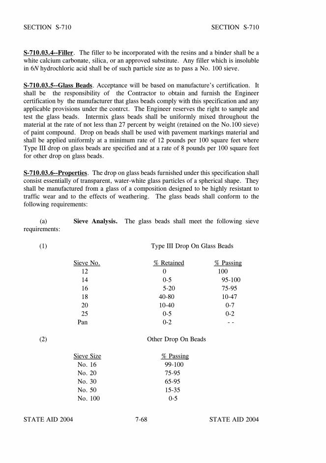
STATE AID 2004 STATE AID 2004
STATE AID 2004 STATE AID 20047-68
SECTION S-710 SECTION S-710
S-710.03.4--Filler. The filler to be incorporated with the resins and a binder shall be awhite calcium carbonate, silica, or an approved substitute. Any filler which is insolublein 6N hydrochloric acid shall be of such particle size as to pass a No. 100 sieve.
S-710.03.5--Glass Beads. Acceptance will be based on manufacture’s certification. Itshall be the responsibility of the Contractor to obtain and furnish the Engineercertification by the manufacturer that glass beads comply with this specification and anyapplicable provisions under the contrct. The Engineer reserves the right to sample andtest the glass beads. Intermix glass beads shall be uniformly mixed throughout thematerial at the rate of not less than 27 percent by weight (retained on the No.100 sieve)of paint compound. Drop on beads shall be used with pavement markings material andshall be applied uniformly at a minimum rate of 12 pounds per 100 square feet whereType III drop on glass beads are specified and at a rate of 8 pounds per 100 square feetfor other drop on glass beads.
S-710.03.6--Properties. The drop on glass beads furnished under this specification shallconsist essentially of transparent, water-white glass particles of a spherical shape. Theyshall be manufactured from a glass of a composition designed to be highly resistant totraffic wear and to the effects of weathering. The glass beads shall conform to thefollowing requirements:
(a) Sieve Analysis. The glass beads shall meet the following sieverequirements:
(1) Type III Drop On Glass Beads
Sieve No. % Retained % Passing 12 0 100 14 0-5 95-100 16 5-20 75-95 18 40-80 10-47 20 10-40 0-7 25 0-5 0-2 Pan 0-2 - -
(2) Other Drop On Beads
Sieve Size % Passing No. 16 99-100 No. 20 75-95 No. 30 65-95 No. 50 15-35 No. 100 0-5
STATE AID 2004 STATE AID 2004
STATE AID 2004 STATE AID 20047-69
SECTION S-710 SECTION S-710
(b) Imperfections. The surface of the glass beads shall be free of pits andscratches. The sizes beads shall have a roundness of 70% minimumaverage (ASTM D 1155) with the exception of the +20 portion, whichshall have a 65% minimum true spheres, tested visually.
(c) Index of Refraction. The index of refraction of the glass beads shallbe not less than 1.50 when tested by the immersion method at 77oF.
(d) Silica Content. The glass beads shall contain not less than 65 percentsilica (Si02).
(e) Chemical Stability. Glass beads which show tendency towarddecomposition, including surface etching, when exposed to paint orpaint constituents will be rejected. The glass beads shall be tested byFederal Specification T-T-B-1325A, Section 4.3.11 (water resistantsoxhlet extraction method) with the following exceptions: Under"Procedure", the size of sample to be tested shall be 25 grams. Undertesting, Paragraph (1), the reflux-time shall be 5 hours and uponexamination after testing the glass beads shall show no dulling effect.Under Paragraph (2), if more than 4.5 mls of 0.1N hydrochloric acidare used to reach the end point, it shall constitute failure of the test.
(f) Flowing Properties. The glass beads shall flow uniformly throughdispensing equipment in atmospheric humidity up to 94%. The dropbeads shall pass the following test: One hundred grams of glass beads,spread evenly and thinly in a suitable container, shall be conditionedat 77oF for 4 hours over a solution of sulfuric acid (Sp. Gr. 1.10) is aclosed desiccator. After 4 hours, the glass beads shall flow readilythrough a clean glass analytical funnel, 60o, 5 mm diameter and 105mm stem. Inside diameter of the stem shall be a nominal 1/4 inch.
(g) Coating: The glass beads used for intermix shall be uncoated. Theglass beads used for the drop on application shall be coated with anadhesion promoting coating. Silicone coated drop on beads shall notbe allowed.
(h) Packaging. The Drop on glass beads shall be delivered in approvedmoisture proof bags consisting of at least five-ply paper constructionunless otherwise specified. Each bag shall contain 50 or 55 poundsnet, and shall be legibly marked with the manufacturer, specificationsand type, lot number, and the month and year the glass beads werepackaged.
STATE AID 2004 STATE AID 2004
STATE AID 2004 STATE AID 20047-70
SECTION S-710 SECTION S-710
S-710.03.7--Paint: In the plastic state, the material shall not give off fumes that are toxicor otherwise injurious to persons or property. The manufacturer shall provide materialsafety sheets for the product.
The temperature versus viscosity characteristic of the plastic material shall remain constantand the material shall not deteriorate in any manner during reheating processes.
There shall be no obvious change in color of the material as a result of repeated heatingor from batch to batch. The maximum elapsed time after application after which normaltraffic will leave no impression or imprint on the new stripe shall be 30 seconds when theair and road surface temperature is approximately (68oF + 6oF). After appreciabledeformation or discoloration, shall remain free from tack, and shall not lift from thepavement under normal traffic conditions within a road temperature range of -20o to150oF. The stripe shall maintain its original dimensions and placement. Cold ductilityof the material shall be such as to permit normal dimensional distortion as a result oftraffic impact within the temperature range specified.
The material shall provide a stripe that has a uniform thickness throughout its crosssection and has the density and character to provide a sharp edge of the line.
The paint compound after heating for 4 hours + 5 minutes at 375o + 3oF and cooled to77oF shall meet the following requirements for daylight reflectance and color, then tested,using a color spectrophotomer with 45o circumferential/0o geometry, illuminate C, and 2o
observer angle. The color instrument shall measure the visible spectrum from 380 to 720nm with a wavelength measurement interval and spectral bandpass of 10 nm.
White: Daylight Reflectance (Y) 75 percent minimum*Yellow: Daylight Reflectance (Y) 42-59 percent
*Shall match Federal 595 Color No. 33538 and Chromaticity limits as follows:x .470 .510 .485 .530y .455 .485 .425 .456
S-710.03.7.1--Specific Gravity. The specific gravity of the paint material shall notexceed 1.87.
S-710.03.7.2--Softening Point. After heating the paint material for 4 hours + 5 min. at375o + 3oF and testing in accordance with ASTM E 28, the material shall have aminimum softening point of 180oF as measured by the ring and ball method.
STATE AID 2004 STATE AID 2004
STATE AID 2004 STATE AID 20047-71
SECTION S-710 SECTION S-710
S-710.03.7.3--Tensile Bond Strength. After heating the paint material for 4 hours + 5min. at 375oF, the tensile bond strength to unprimed, sandblasted portland cementconcrete block, 0.0625 inch thick film drawdown at 375oF, tested at 75o + 2oF shallexceed 180 psi when tested in accordance with ASTM D 4796-88.
S-710.03.7.4--Impact Resistance. After heating the paint material for 4 hours + 5 minat 375o + 3oF, the impact resistance shall be a minimum of 50 inch pounds with no cracksor bond loss when 0.0625-inch thick film drawdown is made at 375oF on an unprimedsandblasted portland cement concrete block, male indentor 5/8 inch, no female Die,tested at 75o + 2oF when tested in accordance with ASTM D 2794 minimum.
S-710.03.7.5--Yellowness Index. The white paint material shall not exceed ayellowness index of 12 when tested in accordance with ASTM D 1925.
(a) Identification - Each package of material shall be stenciled with themanufacturer's name, the type of material and specification number,the month and year the material was packaged and lot number.Lot numbers must begin with the last two digits of the yearmanufactured and be sequential. The letters and numbers used inthe stencils shall be a minimum of 1/2 inch in height.
(b) Packaging - Paint material shall be packaged in suitable containerswhich will not adhere to the product during shipment and storage. Thecontainer of paint material shall weigh approximately 50 pounds.Each container shall designate the color, binder (alkyd orhydrocarbon), spray and user information. The label shall warn theuser that the material shall be heated in the range of 350o - 425oF.
(c) Storage Life - The material shall meet the requirements of thisspecification for a period of one year. The paint must also meltuniformly with no evidence of skins or unmelted particles for thisone year period. Any material not meeting the above requirementsshall be replaced by the manufacturer.
STATE AID 2004 STATE AID 2004
STATE AID 2004 STATE AID 20047-72
SECTION S-710 SECTION S-710
S-710.04-Inorganic Zinc Rich System:
S-710.04.1--Inorganic Zinc Primer. The shop coat or prime coat shall be aself-curing multiple component inorganic zinc rich primer conforming to the requirementsof AASHTO M 300, Type I or Type II. The inorganic zinc rich primer, as applied,shall meet State and Federal regulations on Volatile Organic Compounds (VOC).
The inorganic zinc primer shall be formulated so as to produce a distinct contrast in colorwith the blast cleaned metal surface and the intermediate field coat to be applied thereon.
The inorganic zinc primer must be one from the Mississippi Department ofTransportation's "List of Approved Sources of Materials”.
The paint manufacturer's technical representative who is certified by the NationalAssociation of Corrosion Engineers (NACE) shall be present at the beginning of coatingoperations as neededto provide technical expertise in the application of the coating. This technical expertiseshall be provided without additional cost to the Project. The fabricator is responsible forarranging for the presence of the manufacturer's technical representative.
S-710.04.2--Epoxy Mastic Field Touch-Up Paint. Inorganic zinc primer coat which hasbeen damaged during storage, handling, transporting and/or erection shall be repairedusing epoxy mastic touch-up paint prior to finish coating.
Epoxy mastic touch-up paint shall be manufactured or recommended by the supplier ofthe inorganic zinc primer, shall be as listed on the Mississippi Department ofTransportation's "List of Approved Sources of Materials" and, as applied, shall be VOCcompliant with State and Federal Regulations.
The epoxy mastic touch-up paint shall conform to the same formulation as originallyapproved by the Mississippi Department of Transportation. Determination ofconformance to the originally approved formulation will be based on physical tests, x-raydiffraction pattern and infrared spectrum. The results of these tests shall be in agreementwith the results obtained on the originally approved formulation.
S-710.04.3--Acrylic Latex Intermediate and Top Coats (Field Coats). The acryliclatex field coats shall be manufactured by the supplier of the inorganic zinc primer coat,shall be as listed on the Mississippi Department of Transportation's "List of ApprovedSources of Materials" and, as applied, shall be VOC compliant with State and Federalregulations. The acrylic latex paint shall conform to the same formulation as originallyapproved by MDOT.
STATE AID 2004 STATE AID 2004
STATE AID 2004 STATE AID 20047-73
SECTION S-710 SECTION S-710
Determination of conformance to the originally approved formulation will be based onphysical tests and infrared spectrum of the vehicle component. The infrared spectrum(2.5 to 15 microns) of the vehicle component shall agree with the infrared spectrum of thevehicle component of the originally approved paints in both peak position and relativeintensity of the peaks.
The color of the acrylic latex intermediate coat shall be white in color. The color of theacrylic latex top coat shall be light gray in color.
At the Engineer's request, the paint manufacturer's technical representative who iscertified by the National Association of Corrosion Engineers (NACE) shall be present atthe job site at the beginning of each separate coating operation as needed to providetechnical expertise in the application of the field coats. This technical expertise shall beprovided without additional cost to the Project. The Contractor shall be responsible forarranging for the presence of the manufacturer's technical representative.
S-710.04.4--Mixing of Paint. All paint shall be mixed in accordance with the paintmanufacturer's printed instructions.
S-710.04.5--Packaging and Marking. Multiple component paints shall be furnished inpremeasured packages so as to form one unit of mixed paint when mixed with the vehiclein its container.
The containers of all paints shall be coated as necessary to prevent attack by the paint.Each container shall bear a label with the following information shown thereon: name andaddress of manufacturer, trade mark or trade name, kind of paint, date of manufacture andlot number, mixing instructions and equipment clean up instructions. The VOCcontent shall be stated on the label, product data sheet, or Material Safety Data Sheet.
S-710.04.6--Acceptance Procedure. Prior to use, the Contractor must furnish theCounty Engineer a certificate from the manufacturer, covering each lot of paint in theshipment, attesting that the paint in the shipment conforms to the same formula as thatoriginally approved by the Mississippi Department of Transportation.
Final acceptance of the paint will be based on results of tests performed by theCentral Laboratory of the Mississippi Department of Transportation on samples obtainedby the County Engineer's representative prior to or after delivery. The use of any lot ofpaint prior to its final acceptance shall be prohibited.
STATE AID 2004 STATE AID 2004
STATE AID 2004 STATE AID 20047-74
SECTION S-710 SECTION S-710
S-710.05--Epoxy Mastic System. The coating system shall consist of modified epoxymastic prime coat with a uniform dry film thickness of not less that 5 mil nor more than8 mil and a vinyl finish coat of not less than 3mil nor more than 5 mil.
S-710.05.1--Prime Coat. The prime coat shall be a two-component epoxy masticdesigned as a one-coat high build complete protective coating system with excellentadhesion to rusted steel and old coating systems after such surfaces have been cleaned asspecified.
S-710.05.1.1--Pigment. The silica and metallic aluminum pigment shall include rustinhibitors and adhesion reinforcers/promoters. The aluminum factor shall contain bothleafing and nonleafing types.
S-710.05.1.2--Vehicle. The vehicle shall be a modified epoxy-polymide resinformulated to have suitable insensitivity to moisture and shall contain special wettingagents to insure adequate adhesion.
S-710.05.1.3--Mixed Paint. The mixed paint shall conform to the followingrequirements:
The catalyzed epoxy shall contain 92% ± 2% solids by weight when tested inaccordance with ASTM Designation: D 1644 (modified to a drying time of 72hours at 100oF).
Total solids by volume shall be a minimum of 90%.
The coating shall air cure to a hard, tough film within five days at a temperatureof 75oF. It shall be dry to the touch in 24 hours at 75oF.
The usable pot life of the mixed paint shall be not less that four hours at 75oF andtwo hours at 90oF.
It shall exhibit good compatibility with inorganic zinc primers.
The color shall contrast with the steel and the finish coat.
The catalyzed mixture, after thinning 20% by volume with specified thinner,shall be suitable for spraying in one coat to a 10 mil wet thickness withoutexhibiting runs or sags.
The coating shall be suitable for application with both conventional and airlessspray equipment.
STATE AID 2004 STATE AID 2004
STATE AID 2004 STATE AID 20047-75
SECTION S-710 SECTION S-710
S-710.05.1.4--Packaged Qualities. The paint shall be supplied as a two-package materialwith a one-to-one mixing ratio and shall be well ground and not caked, skinned or badlysettled in the container. Usable shelf life shall be not less than 12 months.
S-710.05.1.5--Flexibility Test. Apply a five mil dry film thickness of paint to oneside of a 4" x 30" x 1/8" steel panel which has been cleaned in accordance withSteel Structures Painting Council SSPC-SP-5, Commercial Blast Cleaning. After thecoating has been cured for two weeks at 75oF, it shall show no signs of cracking or lossof adhesion after the panel is uniformly bent 180o degrees (coated side out) around aneight inch diameter pin.
S-710.05.1.6--Resistance Tests. The panel (3" x 5" x 1/8") meeting the requirementsof ASTM Designation: D 609 shall be prepared by blast cleaning in accordance withSSPC-SP-6, Commercial Blast Cleaning.
After cleaning, the panels shall be exposed to the weather for 30 days to allow uniformrusting. The panels shall then be hand-cleaned with a wire brush in accordance withSSPC-SP-2.
The modified epoxy mastic paint shall be spray applied in one coat to the prepared panelswith a uniform dry film thickness of six mils. Curing shall be in accordance withmanufacturer's recommendations.
Each test shall be performed on one or more panels, and the paint will be unacceptableif it fails one or more of the following tests:
(1) Salt Water Resistance. One or more panels shall be scribed with an X of at leasttwo-inch legs down to the base metal and immersed in 5% sodium chloride at75 ±5oF. The panel(s) shall be examined after 7, 14 and 30 days and shall showneither rusting, blistering, nor softening of the coating beyond 1/16 inch fromthe scribe mark. The solution shall be changed after each examining peroid.
(2) Weathering resistance. One or more panels shall be tested in accordance withASTM Designation: G 23, Type D. The panel(s) shall be placed on test at thebeginning of the wet cycle. After 1,000 hours continuous exposure, the coatingshall show neither rusting, blistering, nor loss of bond.
STATE AID 2004 STATE AID 2004
STATE AID 2004 STATE AID 20047-76
SECTION S-710 SECTION S-710
(3) Salt Fog Resistance. One or more panels shall be scribed with a X of at leasttwo-inch legs down to the base metal. The panel(s) shall then be tested inaccordance with ASTM Designation: B 117. After 1,000 hours continuousexposure, the coating shall show neither loss of bond, rusting nor blisteringbeyond 1/16" from the scribe mark.
S-710.05.2--Vinyl Finish Coat (Field Coat). The vinyl finish coat shall bemanufactured by the supplier of the prime coat. The vehicle shall consist essentially ofvinyl chloride-acetate copolymer resin dissolved in aromatic or ketone and aromaticsolvents. The vinyl coat shall display compatibility with, and adhesion to, the curedprimer film when applied in accordance with the manufacturer's printed instructions.
S-710.05.2.1--Composition.
(a) The vinyl finish coat shall be gray in color and supplied in a singlepackage at a consistency ready for use. It shall be well grounded andnot caked, livered, skinned or badly settled in the container.
(b) The vinyl finish coat shall contain not less than 29% pigment (byweight) and 19% vehicle (by weight) for a total of no less than 48%solids by weight. The weight per gallon shall be 9.6 ± 0.5 pounds at77oF. The grind minimum shall be four. Any extender pigments shallbe barytes.
(c) The vinyl finish coat shall air dry at temperatures of 70oF or above toa hard tough film within four hours, entirely by evaporation of solvents.It shall be dry-to-touch in 25 minutes at 70oF.
S-710.05.3--Packaging. Two-component paint shall be packaged so that one unitof pigment can be mixed with the vehicle in its container. The containers for all paintsshall be coated as necessary to prevent attack by the paint.
Each container shall be plainly marked with the net weight in pounds, net volume in U.S. gallons, color, code number, batch number(s), the name and address of themanufacturer and the date of manufacture. Each container, or label thereon, shall beara true statement of the name and percentage of each component or constituent, bothsolid and liquid. Any package not so marked will be unacceptable.
Each shipment of paint shall be accompanied by complete written instructions andprecautions for use, either on the container label or in a separate document.
STATE AID 2004 STATE AID 2004
STATE AID 2004 STATE AID 20047-77
SECTION S-710 SECTION S-710
S-710.05.4--Acceptance Procedure. Before each shipment is used, the Contractormust furnish the Engineer a certificate from the manufacturer attesting that thecommercial product furnished conforms to the same formula as that previously approvedby MDOT.
If deemed necessary, final acceptance will be based on results of tests performed onsamples obtained by the Engineer prior to or after delivery. Batches of paint found notto be of the approved formulation will be rejected.
S-710.06--Primer for Miscellaneous Metals. The primer shall be a commercial productformulated primarily for industrial use, to combine weather durability, resistance to mildlycorrosive exposures, with good film build and ease of application with all generally usedmethods.
STATE AID 2004 STATE AID 2004
STATE AID 2004 STATE AID 20047-78
SECTION S-711 - REINFORCEMENT AND WIRE ROPE
S-711.01--Reinforcing Steel and Wire Rope. General. All reinforcement used inconcrete construction, unless otherwise stipulated, shall conform to the provisions andrequirements hereinafter set out. The materials when incorporated into the work shall bereasonably free from dirt, paint, oil, grease, loose-thick rust, or other foreign substancesand when deemed necessary, shall be cleaned to the satisfaction of the Engineer.Tight-thin rust or powdering rust on these materials shall not be cause to require cleaning.Reinforcement which has rusted sufficiently to cause it to fail to meet specified physicalproperties or prestressing strands displaying pits visible to the naked eye shall be rejected.
S-711.02--Reinforcing Steel.
S-711.02.1–Bar Reinforcement. Bar reinforcement shall conform to the requirementsof AASHTO Designation: M 31, Grade 60, for billet steel bars.
Bars shall be fabricated as indicated on the plans; shall be cold-bent, unlessotherwise permitted, to the shapes shown on the plans or as directed; and shall be bentprior to being wholly or partially embedded in concrete.
Unless otherwise authorized or provided on the plans, bends or hooks shall not befabricated to a smaller diameter than that indicated for the bend test. Rail steel bars shallbe bent to the specified shapes at the mill or fabricating plant.

STATE AID 2004 STATE AID 2004
STATE AID 2004 STATE AID 20047-79
SECTION S-711 SECTION S-711
The areas and weights to be used in calculations for the various size reinforcing bars shallbe as follows:
STANDARD REINFORCING BARS
Nominal Dimensions-Round Sections
* BarNumbers
Weight(Lbs./Foot)
Diameter(Inches)
Cross-SectionalArea (Sq. Inches)
Perimeter(Inches)
2 (1) 0.167 0.250 0.05 0.786
3 0.376 0.375 0.11 1.178
4 0.668 0.500 0.20 1.571
5 1.043 0.625 0.31 1.963
6 1.502 0.750 0.44 2.356
7 2.044 0.875 0.60 2.749
8 2.670 1.000 0.79 3.142
9 (2) 3.400 1.128 1.00 3.544
10 (2) 4.303 1.270 1.27 3.990
11 (2) 5.313 1.410 1.56 4.430
14 7.65 1.693 2.25 5.32
18 13.60 2.257 4.00 7.09
* The bar numbers are based on the number of 1/8 inch increments in the nominaldiameter of the bar, except as noted in (2) below.
(1) No. 2 bars in plain rounds only
(2) Nos. 9, 10, and 11 are round bars and equivalent in weight and nominalcross-sectional area to the old type 1 inch, 1 1/8 inch, and 1 1/4 inch squarebars, respectively.
STATE AID 2004 STATE AID 2004
STATE AID 2004 STATE AID 20047-80
SECTION S-711 SECTION S-711
S-711.02.2--Bar Mats. Bar mats for concrete pavement reinforcement shall be Grade 60billet steel, AASHTO Designation: M 31, and shall conform to the requirements ofAASHTO Designation: M 54.
S-711.02.3--Steel Wire Fabric. Steel wire fabric shall conform to the requirementsof AASHTO Designation: M 55, or AASHTO Designation: M 221.
S-711.02.4--Dowel Bars and Marginal Bars. Unless otherwise indicated, dowel barsused to span transverse joints and marginal bars shall be plain round bars. They shall beGrade 60 billet steel, AASHTO Designation: M 31.
Before installation, each dowel bar shall be painted with one coat of industrial grade zincbase primer, epoxy or other approved rust inhibitive primer. One half of each dowel barshall be greased with a heavy grease equivalent to 600W or cup grease to prevent bondingwith concrete. The greased end is to be inserted into the dowel bar sleeve described inthe following paragraph.
Sleeves for dowel bars shall be metal or plastic of an approved design, mortar-tight, ofsufficient strength to prevent collapse, and at least two inches in length. A suitable stopshall be provided in the sleeve to permit movement of the dowel bar within the sleeve ofnot less than the thickness of the expansion filler used.
Dowel bars shall be free from burring or other deformations restricting slippage in theconcrete.
S-711.02.5--Tie Bars. Unless otherwise indicated, tie bars used to span longitudinaljoints shall be deformed bars, billet steel, meeting the requirements set forth inS-711.02.1.
S-711.02.6--Cold-Drawn Steel Wire. Cold-drawn steel wire shall conform to therequirements of AASHTO Designation: M 32.
S-711.02.7--Supports for Bar Reinforcement. Metal bar supports shall be fabricatedfrom stainless steel wire conforming to ASTM Designation: A 493, 16% chromiumminimum, or cold-drawn wire with a minimum of 1/2 inch of the height of the leg abovethe form surface protected by one of the following:
Plastic coating conforming to CRSI Standards.Galvanized, conforming to ASTM Designation: A 153, Class D.Stainless steel conforming to ASTM Designation: A 493,16% chromium minimum.Other protective coating as approved by the Engineer.Other supports as approved by the Engineer may be used.
STATE AID 2004 STATE AID 2004
STATE AID 2004 STATE AID 20047-81
SECTION S-711 SECTION S-711
S-711.02.8--Epoxy Coated Reinforcing Bars. All reinforcement to be epoxy coatedshall conform to the requirements of S-711, or as specified on the plans. The epoxy coatshall be in accordance with ASTM Designation: A 775. The Contractor shall furnishwritten certification that the coated reinforcing bars were cleaned, coated and tested inaccordance with the specifications and ASTM Designation: A 775.
S-711.03--Reinforcement for Prestressed Concrete.
S-711.03.1--Pretensioning Reinforcing.
S-711.03.1.1--Uncoated Seven-Wire Stress Relieved Strand for Prestressed Concrete.Uncoated seven-wire stress-relieved strand for prestressed concrete shall conform to therequirements of AASHTO Designation: M 203.
S-711.03.1.2--Uncoated Stress-Relieved Wire for Prestressed Concrete. Uncoatedstress-relieved wire for prestressed concrete shall conform to the requirements ofAASHTO Designation: M 204.
S-711.03.2--Posttensioning Reinforcing.
S-711.03.2.1--Bars. Bars for posttensioning shall be of high tensile strength steel. Theyshall be equipped with wedge-type anchorages which will develop the minimumspecified ultimate bar stress on the nominal bar area.
The minimum physical properties of the bar steel, and of the stress-strain curvedetermined by static tensile tests, shall conform to the following:
Stress at 0.3% elongation, psi ....................... 75,000Stress at 0.7% elongation, psi ...................... 130,000Ultimate stress, psi ................................... 145,000Elongation in 20 diameters, % ............................. 4Modulus of elasticity, psi ....................... 25,000,000
The diameter tolerance of the bar steel shall be from -0.01 to +0.02375 inch.
STATE AID 2004 STATE AID 2004
STATE AID 2004 STATE AID 20047-82
SECTION S-711 SECTION S-711
S-711.03.2.2--Parallel Wire Assemblies. Wire assemblies for posttensioning shallconsist of parallel wires of the number and size shown on the plans. Wires shall conformto the requirements of AASHTO Designation: M 204. Minimum ultimate strengthrequirements for various sizes shall be as follows:
Diameter Minimum Ultimate Strength
(inches) (psi)
0.177 255,000
0.192 251,000
0.225 245,000
0.250 240,000
0.276 236,000
The stress-strain curve for wires shall show the following minimum characteristics, basedon the minimum ultimate strength requirements:
Proportional limit (0.01% offset from tangent), % ................ 55Yield point (0.2% offset from tangent), % ......................... 80 Elongation at rupture ................................................... 4% in 10 inches
The diameter tolerance of wires shall be +0.002 inch.
S-711.03.3--Anchorages for Post-Tensioned Tendons.
S-711.03.3.1--For Bars. Wedge-type anchorages shall be used for bars. The wedgedevice shall develop the minimum ultimate strength specified for the nominal bar area.
Wedge anchorages shall bear against anchor plates fabricated of hot-rolled steel havingphysical characteristics not less than that specified for No. 104 of American Iron andSteel Institute (AISI) Specifications.
STATE AID 2004 STATE AID 2004
STATE AID 2004 STATE AID 20047-83
SECTION S-711 SECTION S-711
S-711.03.3.2--For Parallel Wire Assemblies. Wedge or direct-bearing type anchorageshall be used, generally. The anchorage device shall be capable of developing theultimate strength of the total number of wires anchored. Conical type anchorages shallbe embedded within the ends of the concrete members unless otherwise specified.Anchorages shall generally bear against grids of reinforcing steel of approved type.
S-711.03.3.3--Alternate Anchorage Types. Alternate anchorage types conforming tothe general physical requirements for wedge or direct-bearing type anchorages will bepermitted. All anchorage types shall develop the specified ultimate strength of thereinforcing tendons, or the allowable stress of the tendon will be based on the anchoragestrength.
As a specified exception, threaded anchorages not on upset or oversize reinforcing endswill not be considered for approval.
Any alternate type anchorage, before being considered, will be required to showevidence of being capable of withstanding at least 3,000,000 cycles of twice the maximumlive load stress variation.
S-711.03.4--Tests for Prestressing Reinforcing. The Engineer shall be furnished withthree certified copies of test results for all tests specified below. These tests shall beperformed by the manufacturer or a recognized commercial laboratory at no additionalcost to the Project. The Engineer or his representative shall have the privilege ofwitnessing any or all tests.
S-711.03.4.1--Strand. The physical characteristics of strand shall be determined inaccordance with AASHTO Designation: M 203.
S-711.03.4.2--Bars.
S-711.03.4.2.1--Proof Test. During manufacture, each bar shall be proof tested to aminimum stress of 130,000 psi.
S-711.03.4.2.2--Static Test. From each mill heat, one static test shall be made on anassembled bar and anchorage to determine the physical properties of the steel and theassembly. Such physical properties shall conform to the minimum physical propertieshereinbefore specified.
S-711.03.4.3--Wires and Wire Anchorages. One static test shall have been made fromeach five coils received, except that at least one static test shall have been made for eachshipment. For each 500 anchorages received, or fraction thereof, one anchorage assemblyshall have been tested statically to destruction.
STATE AID 2004 STATE AID 2004
STATE AID 2004 STATE AID 20047-84
SECTION S-712 - GUARDRAIL
S-712.01--Guardrail Posts.
S-712.01.1--General. Unless otherwise specified, guardrail posts may be either wood orsteel. All materials for guardrail posts shall conform to the dimensions and requirementsas shown on the plans or as set out in these specifications.
S-712.01.2--Treated Wood Posts. Treated wood posts shall conform to the size anddimensions as shown on the plans and as hereinafter specified. They shall be inspectedin accordance with S-718 except that the posts may be rough and shall be within + 3/8"of the dimensions shown on the plans. Treatment will be in accordance with AWPAStandard C 14.
S-712.01.3--Steel Posts. Steel posts shall be of the section and length as shown on theplans and shall conform to the requirements of ASTM Designation: A 36.
The posts may be galvanized or shop painted as specified.
S-712.02--Metal Rail. Metal rail for guardrail shall conform to the requirements ofAASHTO Designation: M 180 and as specified on the plans.
S-712.03--Guardrail Hardware. Guardrail hardware such as bolts, nuts and washersshall conform to the requirements of ASTM Designation: A 307 except specified bolts,as shown on the plans, shall meet the requirements of ASTM Designation: A 325(AASHTO Designation: M 164). Galvanizing may be hot-dipped or by a mechanicalmethod all in accordance with ASTM Designation: A 153 except for method of coating.
S-712.04--Guardrail Cable and Anchorage. Cable shall meet the requirements ofAASHTO Designation: M 30 for Type II wire rope.
The anchor rod shall be fabricated of steel conforming to the requirements of ASTMDesignation: A 36. The eye may be drop forged or formed with a full penetration weldand shall develop 100 percent of the rod strength.
The swaged fitting and stud assembly shall be of steel conforming to the requirements ofASTM Designation: A 576, Grade 1035 and shall be annealed and suitable for coldswaging. The fitting shall be galvanized in accordance with ASTM Designation: A 123before swaging. The studs shall conform to the requirements of ASTM Designation:A 449 and shall be galvanized as set forth for guardrail hardware. The swaged fitting,stud and nut shall develop the breaking strength of the wire rope. Three certified copiesof the manufacturer's certificate attesting to the strength of the swage fittings shall befurnished the Engineer.
STATE AID 2004 STATE AID 2004
STATE AID 2004 STATE AID 20047-85
SECTION S-713 - CONCRETE CURING MATERIALS AND ADMIXTURES
S-713.01--Curing Materials. Concrete curing agents (including water and earth) shallbe free of any ingredients which may damage or be detrimental to the concrete. Suchagents, unless otherwise specified, shall conform to the requirements hereinafter set forth.
S-713.01.1--Burlap Cloth. Burlap to be used for curing concrete shall conform to therequirements of AASHTO Designation: M 182.
Class 3 burlap shall be used (one or two layers as required) except that substitutions ofother classes may be made, provided their combined weight will equal or exceed theweight required.
S-713.01.2--Liquid Membrane Compound. Membrane-forming compound for curingconcrete shall conform to the requirements of AASHTO Designation: M 148.
Unless otherwise specified, only Type 2 (White Pigmented) will be permitted for use.
The use of liquid membrane for curing concrete surfaces which are to have a rubbedfinish or faces of construction joints will not be permitted.
S-713.01.3--Polyethylene Sheeting (White). White polyethylene sheeting shallconform to the requirements of AASHTO Designation: M 171 for white opaquepolyethylene film.
S-713.02--Admixtures for Concrete. Air-entraining admixtures used in portland cementconcrete shall comply with AASHTO Designation: M 154. Set-retarding, accelerating,and/or water reducing admixtures shall comply with AASHTO Designation: M 194.
In order to obtain approval of an admixture, the MDOT Materials Engineer shall havebeen furnished certified test reports, made by an acceptable independent laboratoryregularly inspected by the Cement and Concrete Reference Laboratory of the NationalBureau of Standards, which show that the admixture meets all the requirements of theapplicable AASHTO Standard Specification.
The Engineer reserves the right to sample, for check tests, any shipment or lot ofadmixture delivered to a project.
The Engineer reserves the right to require tests of the material to be furnished, using thespecific cement and aggregates proposed for use on the project, as suggested in AASHTODesignation: M 154 and outlined in AASHTO Designation: M 194.
STATE AID 2004 STATE AID 2004
STATE AID 2004 STATE AID 20047-86
SECTION S-713 SECTION S-713
After an admixture has been approved, the Contractor shall submit to the MDOTMaterials Engineer, with each new lot of material shipped, a notarized certification fromthe manufacturer showing that the material is of the same composition as that originallyapproved, and that the material has not been in any way changed or altered.
Admixtures containing chlorides will not be permitted.
Failure to maintain compliance with any requirement of these specifications shall be causefor rejection of any previously approved source or brand of admixture.
When an admixture is used in portland cement concrete, it shall be the responsibility ofthe Contractor to produce satisfactory results.
STATE AID 2004 STATE AID 2004
STATE AID 2004 STATE AID 20047-87
SECTION S-714 - MISCELLANEOUS MATERIALS
S-714.01--Water.
S-714.01.1--General. All water used shall be free from injurious quantities of oil, acid,alkali, or vegetable matter; shall be reasonably clear; and shall not be brackish. If at anytime water from source becomes of unsatisfactory quality or of insufficient quantity, theContractor shall provide satisfactory water from some other source. Where the sourceof water is relatively shallow, the Engineer may require the intake to be so enclosed asto exclude silt, mud, grass, or other foreign materials.
Requirements for impurities set out in these specifications are general maximums whichmay be used as a basis for acceptance. However, if the preliminary analysis indicates thatany of the specified limits for acidity or alkalinity, organic solids, or inorganic solids areexceeded, the water may be further tested as provided in S-714.01.6 to determine itssuitability for the purpose intended.
S-714.01.2--Water for Use in Concrete. Water used in mixing of concrete, mortar, andgrout shall be as set out above. In addition, the water shall not contain impurities inexcess of the following limits:
Acidity or alkalinity(calculated in terms of calcium carbonate), % ......................... 0.05Total organic solids, % .................................................... 0.05Total inorganic solids, % .................................................. 0.05
The tests for organic solids and inorganic solids may be waived by the MDOT MaterialsEngineer on water samples from ponds, lakes, streams, rivers, and ditches in all exceptthe following counties: Pearl River, Stone, George, Hancock, Harrison and JacksonCounties.
S-714.01.3--Water for Use in Chemically-Stabilized Subbase and Base. Water usedin construction of subbases or bases which contain cement, lime, or other chemicaladditive shall be as set out in S-714.01.1 and, in addition, shall not contain impuritiesin excess of the following limits:
Acidity or alkalinity(calculated in terms of calcium carbonate), % ......................... 0.5Total organic solids, % .................................................... 0.05Total inorganic solids, % .................................................. 0.20
STATE AID 2004 STATE AID 2004
STATE AID 2004 STATE AID 20047-88
SECTION S-714 SECTION S-714
The tests for organic solids and inorganic solids may be waived by the MDOT MaterialsEngineer on water samples from ponds, lakes, streams, rivers, and ditches in all exceptthe following counties: Pearl River, Stone, George, Hancock, Harrison and JacksonCounties.
S-714.01.4--Water for Use in Granular Subbase and Base. Water for use in granularsubbases or bases may be brackish.
S-714.01.5--Water for Use in the Planting and Establishment of Vegetation. Waterused for planting and establishment of vegetation shall meet the requirements ofS-714.01.1 as related to injurious quantities of oil, acid, or alkali and shall not bebrackish.
S-714.01.6--Tests. Water obtained, from a potable source approved by the MississippiState Health Department will not be required to be tested; otherwise, as applicable, aroutine analysis of the sample of water submitted will be made. If the routine analysisindicates that any of the specified limits for acidity or alkalinity, organic solids, orinorganic solids are exceeded, the water may be further tested by either or both of thefollowing methods as determined by the MDOT Materials Engineer.
1. A chemical analysis to determine the nature of the specified characteristics forwhich minimum values are established.
2. Strength and Time-of-Set Test. Results of additional tests may be consideredsatisfactory if:
(a) The solids are found to be not detrimental to the materials with which thewater is used;
(b) The alkali carbonates and bicarbonates do not exceed 0.1% by weight ofwater when the combination of carbonates and bicarbonates is calculatedto sodium carbonate, Na2CO3;
(c) The 28-day strength of mortar with the water is not less than 90% of thatmade with distilled water; and
(d) The time of set is not less than 45 minutes.
In general, water will be approved if it complies with the applicable requirements of theStandard Specifications, or if the results of additional tests as provided above aredetermined by the MDOT Materials Engineer to be satisfactory.
No formal tests of water used for granular subbase, base, or embankment construction,or in connection with the planting and establishment of vegetation will be made unless theEngineer questions the quality of the water.

STATE AID 2004 STATE AID 2004
STATE AID 2004 STATE AID 20047-89
SECTION S-714 SECTION S-714
S-714.02--Calcium Chloride. Calcium chloride shall conform to the requirements ofAASHTO Designation: M 144. Calcium chloride shall not be used in concrete which willbe prestressed; nor shall it be used in other concrete unless specifically approved by theEngineer.
S-714.03--Lime.
S-714.03.1--General. Lime shall be stored and handled in closed, weather-proofcontainers until used. If local storage is provided, lime shall be used only from approvedstorage facilities and shall meet the requirements of the contract at the time of use.
S-714.03.2--Hydrated Lime. Hydrated lime for use in mortar shall conform to therequirements of ASTM Designation: C 207, Type N.
Hydrated lime for soil stabilization shall conform to the following requirements:
Calcium and magnesium oxides (nonvolatile basis), %, min. .............................................. 90Carbon dioxide, %, maximum ............................................. 7Moisture loss, 2 hrs. @ 120oC, maximum ............................... 3
Gradation of Residue:Retained on No. 30 sieve, %, maximum .................... 2.5Retained on No. 200 sieve, %, maximum .................... 15
STATE AID 2004 STATE AID 2004
STATE AID 2004 STATE AID 20047-90
SECTION S-714 SECTION S-714
S-714.03.3--Quick Lime.
S-714.03.3.1--Granular or Pelletized Quick Lime. Granular or pelletized quick limefor soil stabilization shall be a commercial granular or pelletized quick lime and shallconform to the following requirements prior to slaking:
Calcium and magnesium oxides, nonvolatile basis, %, minimum .... 90Carbon dioxide, %, maximum ........................................ 7Gradation, percent passing by weight:¾ inch sieve ................................................................... 100No. 4 sieve .................................................................... 0-30
The Contractor shall furnish certified test reports with each shipment of quick limeattesting to the purity of the lime and that the lime meets the requirements of thespecifications; however, the material shall be subject to inspection, test, or rejection bythe Engineer at any time.
S-714.03.3.2--Dry Quick Lime. Dry quick lime used for soil stabilization by the dryapplication method shall be a commercial quick lime and shall conform to the followingrequirements after two minutes on a Ro-tap shaker:
Sieve Percent Passing By WeightNo. 10 100No. 20 90 - 100No. 100 0 - 20No. 200 0 - 5
Dry quick lime shall meet the slaking standards as defined in ASTM Designation: C 110,and shall reach maximum heat rise in no more than six (6) minutes.
The Contractor shall furnish certified test reports with each shipment of quick limeattesting to the purity of the lime and that the lime meets the requirements of thespecifications; however, the material shall be subject to inspection, test, or rejection bythe Engineer at any time.
S-714.03.4--Bag Lime. When bag lime is used, the bag shall bear the weight certifiedby the manufacturer. Bags varying more than five percent from the certified weight willbe rejected, and the average weight of 50 bags in any shipment taken at random shall notbe less than the certified weight. Bag lime shall conform to the requirements of hydratedor quick lime as applicable.
STATE AID 2004 STATE AID 2004
STATE AID 2004 STATE AID 20047-91
SECTION S-714 SECTION S-714
S-714.03.5--Limestone Dust. The source of the material shall be approved by theEngineer and meet the following gradation requirements:
SIEVE PERCENT PASSINGNo. 30 95-100No. 200 20-100
S-714.04--Sodium Chloride. Sodium chloride shall conform to the requirements ofAASHTO Designation: M 143.
S-714.05--Fly Ash.
S-714.05.1--General. When required or permitted in construction, fly ash shall beobtained from an approved source. The acceptance of fly ash shall be based on certifiedtest reports, certification of shipment from the supplier, and tests performed on samplesobtained after delivery in accordance with the Office of State Aid Road Construction’sStandard Operating Procedures.
Different classes of fly ash or different sources of the same class shall not be mixed orused in the construction of a structure or unit of a structure, without written permissionfrom the Engineer. The Contractor shall provide suitable means for storing and protectingthe fly ash against dampness. Fly ash, which for any reason, has become partially set orwhich contains lumps of caked fly ash shall not be used.
The temperature of the bulk fly ash shall not be greater than 165oF at the time ofincorporation into the work.
In addition to the above requirements fly ash shall meet the following specificrequirements for the intended use.
S-714.05.2-Fly Ash for Use in Concrete. When used with portland cement (Types I orII) in the production of concrete, grout, or in soil stabilization, the fly ash shall meet therequirements of AASHTO Designation: M 295, Class C or Class F, with the followingexceptions:
The loss on ignition shall not exceed 6.0 percent.
The Pozzolanic activity index with portland cement, at 7 days, shall be at least 55 percentof the control mix. The water requirement shall not exceed 105 percent of the controlmix.
Fly ash shall not be used with portland cement Type IP.
STATE AID 2004 STATE AID 2004
STATE AID 2004 STATE AID 20047-92
SECTION S-714 SECTION S-714
S-714.05.3-Fly Ash for Soil Stabilization. When used with hydrated lime in soilstabilization, the class of fly ash shall be as specified in the contract. The fly ash, whenmixed with hydrated lime and soil or soil-aggregate, shall produce the minimum designcharacteristics for the course to be stabilized. The fly ash shall meet the requirements ofAASHTO Designation: M 295 for the class specified, except the loss on ignition shall notexceed 10.0 percent.
S-714.06--Ground Granulated Blast Furnace Slag (GGBFS).
S-714.06.1--General. GGBFS shall be obtained from an approved source. Theacceptance of GGBFS shall be based on certified test reports, certification of shipmentfrom the supplier and tests performed on samples obtained after delivery in accordancewith the Office of State Aid’s Standard Operating Procedures.
The Contractor shall provide suitable means for storing and protecting the GGBFS againstdampness and contamination. Separate storage silos, bins, or containers shall be providedfor GGBFS. GGBFS which has become partially set, caked or contains lumps shall notbe used.
The Engineer shall be notified in writing of the nature, amount and identity of anyprocessing or other additions made to the GGBFS during production.
GGBFS from different mills shall not be mixed or used alternately in any one class ofconstruction or structure without written permission from the Engineer; except that thisrequirement will not be applicable to cement treatment of design soil, subbases or bases.
In addition to these requirements, GGBFS shall meet the following specific requirements.
S-714.06.2–Specific Requirements. GGBFS shall meet the requirements of AASHTODesignation: M 302, Grade120. GGBFS shall contain no chlorides.
S-714.07--Blank.
STATE AID 2004 STATE AID 2004
STATE AID 2004 STATE AID 20047-93
SECTION S-714 SECTION S-714
S-714.08--Frames, Grates, Covers, and Ladder Rungs. Metal units shall conform tothe plan dimensions and to the applicable requirements in S-716 or S-717.
Galvanizing, where specified for these units, shall conform to the requirements ofAASHTO Designation: M 111, unless otherwise designated.
S-714.09--Blank.
S-714.10--Elastomeric Bearings.
S-714.10.1--General. This work shall consist of furnishing and installing elastomericbearings in accordance with the plans and these specifications. All required testing andfurnishing of sample bearings is considered to be part of the covered work. Shopdrawings shall be approved by the Engineer prior to beginning of fabrication orproduction of bearings. Elastomeric bearings, as herein defined, shall include plain ornonreinforced pads consisting of elastomer only, and reinforced or laminated bearingsconsisting of elastomer reinforced with steel laminates.
All elastomeric bearings shall be furnished to the dimensions indicated on the plans. Theyshall be composed of the specified elastomer type, grade and hardness (or shear modulus);shall be adequate for the specified design load; shall be tested at the appropriate level;and shall satisfy any special requirements as shown on the plans.
S-714.10.2--Elastomer. The raw elastomer shall be virgin polycholoroprene (Neoprene),Grade 3 (Ref. ASTM Designation: D 4014).
Elastomer for plain or non reinforced bearings shall be 70-Durometer, adequate for 800psi design compression stress, and shall be tested to Level I as hereinafter described.
Unless otherwise shown on the plans, elastomer for laminated or reinforced bearingshall be 50-Durometer, adequate for 1,000 psi design compression stress, and shall betested to Level I as hereinafter described.
An elastomer of higher grade number may be substituted for the specified grade.
The elastomer compound shall also meet the minimum requirements of Table I except asotherwise specified by the Engineer. When test specimens are cut from the finishedproduct, a 10 percent variation in physical properties shall be permitted. All materialtests shall be carried out at 73oF + 4oF unless otherwise specified.
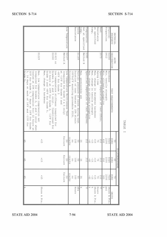
STATE AID 2004 STATE AID 2004
STATE AID 2004 STATE AID 20047-94
SECTION S-714 SECTION S-714
TABLE I
POLYCHOROPRENE
MATERIAL
PROPERTY
ASTM
DESIGNATION
TEST REQUIREMENTS
50
DURO
60
DURO
70
DURO
UNITS
Physical
Properties
D2240
D412
Hardness
Min. tensile strength
Min. ultimate elongation
50±5
2250
400
60±5
2250
350
70±5
2250
300
Shore A Pts.
psi
%Heat
Resistance
at specified
temp.
D573
Specified temperature of test-22hrs.
Aging time
Max. change in durometer hardness
Max. change in tensile strength
Max. change in ultimate elongation
212
70
+15
-15
-40
212
70
+15
-15
-40
212
70
+15
-15
-40
oFHours
Shore A Pts.
%%Compression
Set at specified
temp.
D395
Method B
Specified temperature of test degrees
Max. permissible set
212
35
212
35
35
oF%Ozone
Resistance
D1149
Partial pressure of ozone during test
Duration of test Tested at 20% strain
100oF±2oF mounting procedure D518,
Procedure A
50
100
no
cracks
50
100
no
cracks
50
100
no
cracks
mPa
Hours
Low Temperature
D2137
Method A
Low temperature Brittleness Test
(required for Grade 3 & 5 only)
at -13oF for Grade 3 and
-40oF for Grade 5
no
failure
no
failure
no
failure
D1415 or
D2240
Low temperature stiffness (required for
Grades 2, 3 and 5 only). Conditioned for
22 hours at 14oF for Grade 2, -13oF for
Grade 3 and -40oF for Grade 5.
Max. change in hardness
+15
+15
+15
Shore A Pts.
D1229
Max. low temperature compression set
(required for Grades 2, 3 and 5 only) when
tested at 25% compression for: 22 hours at
32oF for Grade 2, 7 days at 14oF for Grade
3, 14 days at each of 14oF and -13oF for
Grade 5.
65
65
65
%
STATE AID 2004 STATE AID 2004
STATE AID 2004 STATE AID 20047-95
SECTION S-714 SECTION S-714
S-714.10.3--Steel Laminates. Steel laminates used for reinforcement shall be madefrom rolled mild steel conforming to ASTM Designation: A 36 or A 1011, unlessotherwise specified by the Engineer. The laminates shall have a minimum nominalthickness of 16-gauge. Holes in plates for manufacturing purposes shall be consideredin design.
S-714.10.4--Bonding Adhesive. The vulcanized bond between the elastomer andsteel laminates shall have a minimum peel strength of 40 pounds per inch. The peelstrength shall be performed in accordance with ASTM Designation: D 429, MethodB.
S-714.10.5--Fabrication.
S-714.10.5.1--General. Plain pads shall be cast as a single unit in individual molds underheat and pressure except leveling pads 3/8 inch or less in thickness may be sheared.Bearings with steel laminates shall be cast as a unit in a mold and bonded and vulcanizedunder heat and pressure. The molds shall have standard shop practice mold finish. Theinternal steel laminates shall be sandblasted and cleaned of all surface coating rust and millscale before bonding, shall be free of sharp edges and burrs, and shall have a minimumedge cover of 1/8 inch.
Flash tolerance, finish, and appearance shall meet the requirement of the latest edition ofthe Rubber Handbook as published by the Rubber Manufacturers Association, Inc., RMAF3 and T.063 for molded bearings and RMA F2 for extruded bearings.
S-714.10.5.2--Tolerances. Plain pads and laminated bearings shall be built to the designdimensions and these specifications with the following tolerances:
(a) Overall Vertical Dimensions (Inches)Design Thickness 1 1/4" or less -0, +1/8"Design Thickness >1 1/4" -0, +1/4"
(b) Overall Horizontal Dimensions36" and less -0, +1/4"over 36" -0, +1/2"
(c) Thickness of Individual Layersof ElastomerLaminated Bearings Only at ±20% of design valueany point within the bearing but no more than ±1/8"
STATE AID 2004 STATE AID 2004
STATE AID 2004 STATE AID 20047-96
SECTION S-714 SECTION S-714
(d) Variation from a Plane Parallelto the Theoretical Surfaceas determined by measurementsat the edge of the bearings:
Top slope relative tobottom of no morethan .005 radians
Sides 1/4"
(e) Position of Exposed ConnectionMembers 1/8"
(f) Edge cover of Embedded Laminatesor Connection Members -0, +1/8"
(g) Size of Holes, Slot or Inserts +1/8"
(h) Position of Holes, Slots, or Inserts +1/8"
S-714.10.6--Acceptance Procedure. The acceptance criteria shall be at two levels.Level I acceptance shall be applied to all elastomeric bearings. Level II acceptancecriteria shall be applied as required on the plans or contract documents. Level II criteriashall also be used to resolve differences over the acceptance of bearings to which onlyLevel I tests have been applied.
Level I criteria require that bearing pads be manufactured according to this specificationand any additional requirements specified on the plans. The manufacturer shall proofload each steel reinforced bearing with a compressive load of 1500 psi. If bulgingpatterns imply laminate placement which does not satisfy design criteria andmanufacturing tolerances or if bulging suggests poor laminate bond, the bearing shall berejected. If there are 3 separate surface cracks which are greater that 0.08 inch wide and0.08 inch deep, the bearing shall be rejected.
A copy of the proof loading results for each lot of steel reinforced bearings shall befurnished to the Engineer prior to shipment of the bearings.
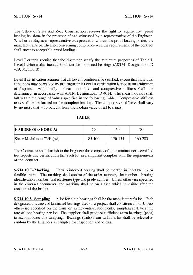
STATE AID 2004 STATE AID 2004
STATE AID 2004 STATE AID 20047-97
SECTION S-714 SECTION S-714
The Office of State Aid Road Construction reserves the right to require that proofloading be done in the presence of and witnessed by a representative of the Engineer.Whether an Engineer representative was present to witness the proof loading or not, themanufacturer's certification concerning compliance with the requirements of the contractshall attest to acceptable proof loading.
Level I criteria require that the elastomer satisfy the minimum properties of Table I.Level I criteria also include bond test for laminated bearings (ASTM Designation: D429, Method B).
Level II certification requires that all Level I conditions be satisfied, except that individualconditions may be waived by the Engineer if Level II certification is used as an arbitrationof disputes. Additionally, shear modulus and compressive stiffness shall bedetermined in accordance with ASTM Designation: D 4014. The shear modulus shallfall within the range of values specified in the following Table. Compressive stiffnesstests shall be performed on the complete bearing. The compressive stiffness shall varyby no more that ±10 percent from the median value of all bearings.
TABLE
HARDNESS (SHORE A) 50 60 70
Shear Modulus at 73oF (psi) 85-100 120-155 160-200
The Contractor shall furnish to the Engineer three copies of the manufacturer's certifiedtest reports and certification that each lot in a shipment complies with the requirementsof the contract.
S-714.10.7--Marking. Each reinforced bearing shall be marked in indelible ink orflexible paint. The marking shall consist of the order number, lot number, bearingidentification number, and elastomer type and grade number. Unless otherwise specifiedin the contract documents, the marking shall be on a face which is visible after theerection of the bridge.
S-714.10.8--Sampling. A lot for plain bearings shall be the manufacturer's lot. Eachdesignated thickness of laminated bearings used on a project shall constitute a lot. Unlessotherwise specified on the plans or in the contract documents, sampling shall be at therate of one bearing per lot. The supplier shall produce sufficient extra bearings (pads)to accommodate this sampling. Bearings (pads) from within a lot shall be selected atrandom by the Engineer as samples for inspection and testing.
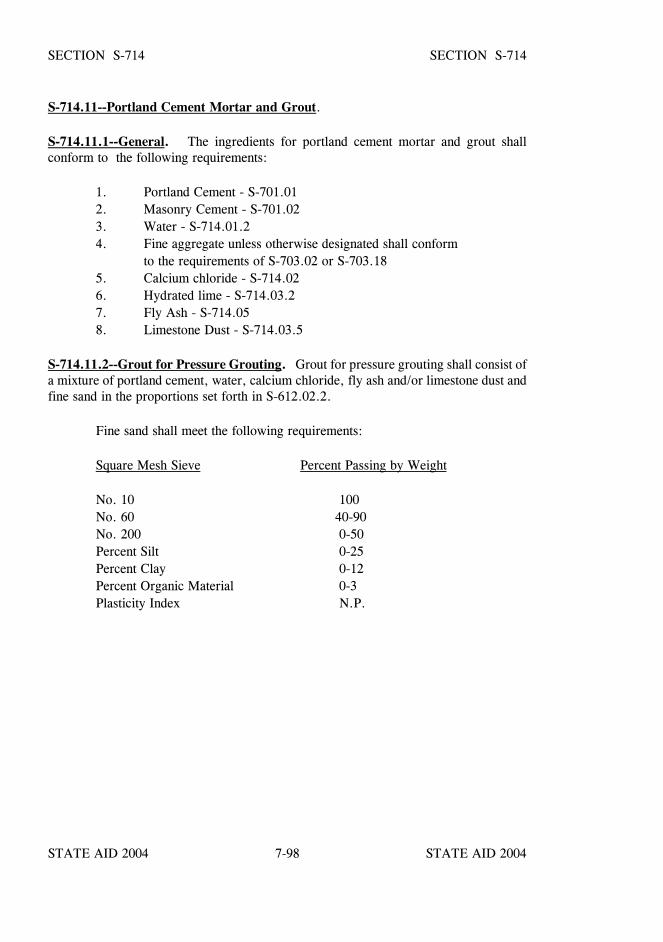
STATE AID 2004 STATE AID 2004
STATE AID 2004 STATE AID 20047-98
SECTION S-714 SECTION S-714
S-714.11--Portland Cement Mortar and Grout.
S-714.11.1--General. The ingredients for portland cement mortar and grout shallconform to the following requirements:
1. Portland Cement - S-701.012. Masonry Cement - S-701.023. Water - S-714.01.24. Fine aggregate unless otherwise designated shall conform
to the requirements of S-703.02 or S-703.185. Calcium chloride - S-714.026. Hydrated lime - S-714.03.27. Fly Ash - S-714.058. Limestone Dust - S-714.03.5
S-714.11.2--Grout for Pressure Grouting. Grout for pressure grouting shall consist ofa mixture of portland cement, water, calcium chloride, fly ash and/or limestone dust andfine sand in the proportions set forth in S-612.02.2.
Fine sand shall meet the following requirements:
Square Mesh Sieve Percent Passing by Weight
No. 10 100No. 60 40-90No. 200 0-50Percent Silt 0-25Percent Clay 0-12Percent Organic Material 0-3Plasticity Index N.P.
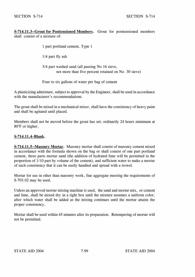
STATE AID 2004 STATE AID 2004
STATE AID 2004 STATE AID 20047-99
SECTION S-714 SECTION S-714
S-714.11.3--Grout for Posttensioned Members. Grout for posttensioned membersshall consist of a mixture of:
1 part portland cement, Type 1
1/4 part fly ash
3/4 part washed sand (all passing No 16 sieve,not more than five percent retained on No. 30 sieve)
Four to six gallons of water per bag of cement
A plasticizing admixture, subject to approval by the Engineer, shall be used in accordancewith the manufacturer's recommendations.
The grout shall be mixed in a mechanical mixer, shall have the consistency of heavy paintand shall be agitated until placed.
Members shall not be moved before the grout has set; ordinarily 24 hours minimum at80oF or higher.
S-714.11.4–Blank.
S-714.11.5--Masonry Mortar. Masonry mortar shall consist of masonry cement mixedin accordance with the formula shown on the bag or shall consist of one part portlandcement, three parts mortar sand (the addition of hydrated lime will be permitted in theproportion of 1/10 part by volume of the cement), and sufficient water to make a mortarof such consistency that it can be easily handled and spread with a trowel.
Mortar for use in other than masonry work, fine aggregate meeting the requirements ofS-703.02 may be used.
Unless an approved mortar mixing machine is used, the sand and mortar mix, or cementand lime, shall be mixed dry in a tight box until the mixture assumes a uniform color,after which water shall be added as the mixing continues until the mortar attains theproper consistency.
Mortar shall be used within 45 minutes after its preparation. Retempering of mortar willnot be permitted.

STATE AID 2004 STATE AID 2004
STATE AID 2004 STATE AID 20047-100
SECTION S-714 SECTION S-714
S-714.11.6--Rapid Setting Commercial Grouts and Concrete Patching Compounds.Rapid setting commercial grouts and concrete patching compounds must be approved forlisting in the MDOT’s “Approved Sources of Materials” prior to use, and shall bepremeasured and packaged dry by the manufacturer. All liquid solutions included by themanufacturer as components of the packaged material shall be packaged in a watertightcontainer. The manufacturer may include aggregates in the packaged material orrecommend the addition of Contractor furnished aggregates.
The type, size and quantity of aggregates, if any, to be added at the job site shall be inaccordance with the manufacturer's recommendations and shall meet the requirements ofS-703.02 for fine aggregate and S-703.03 for coarse aggregate. Required mixing waterto be added at the job site shall meet the requirements of S-714.01.2.
Only those bonding agents, if any, recommended by the manufacturer of the grout orpatching compounds may be used for increasing the bond to old concrete or mortarsurfaces.
Grout or patching compounds containing chlorides will not be permitted when in contactwith steel.
Site preparation, proportioning of materials, mixing, placing and curing shall beperformed in accordance with the manufacturer's recommendation for the specific typeof application, and the Contractor shall furnish a copy of these recommendations to theEngineer.
Rapid setting non-shrink commercial grouts and concrete patching compounds, includingcomponents to be added at the job site, shall conform to the following physicalrequirements:
Compressive strength shall equal or exceed 3000 psi in 24 hours when tested inaccordance with Mississippi Test Method MT-4.
Bond strength shall equal or exceed 100 psi in 24 hours when tested in accordancewith Mississippi Test Method MT-4.
The material shall not shrink, and the increase in length at 28 days shall not begreater than 0.3% when tested in accordance with Mississippi Test Method MT-4.
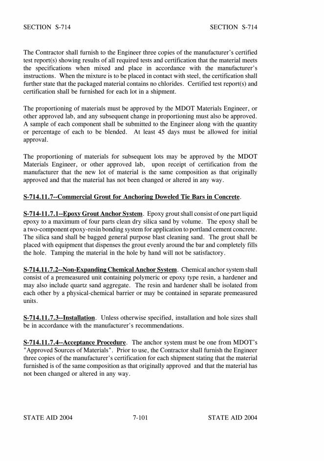
STATE AID 2004 STATE AID 2004
STATE AID 2004 STATE AID 20047-101
SECTION S-714 SECTION S-714
The Contractor shall furnish to the Engineer three copies of the manufacturer’s certifiedtest report(s) showing results of all required tests and certification that the material meetsthe specifications when mixed and place in accordance with the manufacturer'sinstructions. When the mixture is to be placed in contact with steel, the certification shallfurther state that the packaged material contains no chlorides. Certified test report(s) andcertification shall be furnished for each lot in a shipment.
The proportioning of materials must be approved by the MDOT Materials Engineer, orother approved lab, and any subsequent change in proportioning must also be approved.A sample of each component shall be submitted to the Engineer along with the quantityor percentage of each to be blended. At least 45 days must be allowed for initialapproval.
The proportioning of materials for subsequent lots may be approved by the MDOTMaterials Engineer, or other approved lab, upon receipt of certification from themanufacturer that the new lot of material is the same composition as that originallyapproved and that the material has not been changed or altered in any way.
S-714.11.7--Commercial Grout for Anchoring Doweled Tie Bars in Concrete.
S-714-11.7.1--Epoxy Grout Anchor System. Epoxy grout shall consist of one part liquidepoxy to a maximum of four parts clean dry silica sand by volume. The epoxy shall bea two-component epoxy-resin bonding system for application to portland cement concrete.The silica sand shall be bagged general purpose blast cleaning sand. The grout shall beplaced with equipment that dispenses the grout evenly around the bar and completely fillsthe hole. Tamping the material in the hole by hand will not be satisfactory.
S-714.11.7.2--Non-Expanding Chemical Anchor System. Chemical anchor system shallconsist of a premeasured unit containing polymeric or epoxy type resin, a hardener andmay also include quartz sand aggregate. The resin and hardener shall be isolated fromeach other by a physical-chemical barrier or may be contained in separate premeasuredunits.
S-714.11.7.3--Installation. Unless otherwise specified, installation and hole sizes shallbe in accordance with the manufacturer's recommendations.
S-714.11.7.4--Acceptance Procedure. The anchor system must be one from MDOT’s"Approved Sources of Materials". Prior to use, the Contractor shall furnish the Engineerthree copies of the manufacturer's certification for each shipment stating that the materialfurnished is of the same composition as that originally approved and that the material hasnot been changed or altered in any way.
STATE AID 2004 STATE AID 2004
STATE AID 2004 STATE AID 20047-102
SECTION S-714 SECTION S-714
Each day an in-place tension test shall be performed at random on a tie bar with amaximum curing time of two hours. If the test fails to meet the total load required tostress the bar to 50,000 psi, three additional tests shall be made at random. If any of theadditional tests fail, all bars installed on that day shall be tested and any bar that fails shallbe replaced. The Contractor shall furnish the testing device which shall include a certifiedcalibration chart. No separate measurement for payment will be made for the testingdevice.
S-714.11.8--Epoxy Joint Repair System.
S-714.11.8.1--General. When the epoxy system is from MDOT’s current list of“Approved Sources of Materials”, the Contractor shall furnish the Engineer three copiesof the manufacturer's certification, for each shipment, stating that the epoxy and allcomponents is the same composition as that originally approved and that the material hasnot been changed or altered in any way.
If the materials proposed for use are not from the MDOT’s current list of approvedmaterials, a sample of the epoxy and all components required for the epoxy mortar mixshall be submitted to the Engineer for evaluation and approval at least 30 calendar daysprior to placement. Subsequent approval of each shipment may be by manufacturer'scertification as set out above.
A representative of the epoxy manufacturer must be present for sufficient time to assurethat the Contractor is properly schooled in the use of the epoxy materials.
S-714.11.8.2--Epoxy Resin. The material shall meet the requirements of ASTMDesignation: C 881, Type I, Grade 2, Class C.
S-714.11.8.3--Silica Sand. The material shall be bagged general purpose blast cleaningsand.
S-714.11.8.4--Epoxy Mortar Mix. The mortar mix shall consist of one part liquid epoxyto 3.5 parts clean dry sand by volume.
S-714.11.8.5--Mixing and Curing. Mixing of all epoxy materials shall be accomplishedwith a mechanical mixer. A trial batch of mortar, approximately one cubic foot, will bemixed and used for joint repair. From this batch, the pot life and subsequent amount ofmaterial to be mixed will be determined.
S-714.12--Sprayed Finish for Concrete Surfaces. The spray material shall be anapproved commercial product designed specifically for a sprayed finish and when appliedto the concrete specimens at a rate of one gallon per 50 square feet shall conform to thefollowing requirements:

STATE AID 2004 STATE AID 2004
STATE AID 2004 STATE AID 20047-103
SECTION S-714 SECTION S-714
S-714.12.1--Freeze-Thaw Test. Cast and cure three concrete specimens, not less than4" x 6" x 6", of the mix designed for the structure. Fourteen days moist curing with adrying period in room air at 60o to 80oF for 24 hours before coating with spray finish isrequired. Caution shall be taken that there be no excessive oil on specimen forms. Coatsides of specimens (brush permitted) as hereinbefore set out and cure at room temperaturefor 48 hours; after which:
1. Immerse in water at room temperature (60o to 80oF) for three hours;remove and,
2. Place in cold storage at -15oF for one hour; remove and,
3. Thaw at room temperature (60o to 80oF) for one hour.
4. Repeat Steps 2 and 3 to complete a total of 50 cycles.
At the end of 50 cycles of Freeze/Thaw Test, the specimens shall show no visible defects.
S-714.12.2--Accelerated Weathering. Material shall be subjected to a 5000 hourexposure test in accordance with ASTM Designation: G 151. Testing shall be performedin conjunction with either ASTM Designation: G 153, Carbon Arc Light Apparatus, orASTM Designation: G 155, Xenon Arc Light Apparatus. Test Exposure Conditions shallbe as specified in Table X1.1, Cycle 1 in ASTM Designation: G 153, or Table X3.1,Cycle 1 in ASTM Designation: G 155. At the end of the exposure test, the exposedsample must not show any chipping, flaking or peeling.
S-714.12.3--Fungus Growth Resistance. Material to be used shall pass a fungusresistance test as described by ASTM Designation: D 3273 with a minimum incubationperiod of 21 days where no growth shall have been indicated after the test.
S-714.12.4--Color. The color of the finish shall be that deemed by the Engineer to beas close as practicable to the color of a rubbed concrete finish.
S-714.12.5--Testing and Certification. All testing shall be performed by aqualified commercial testing laboratory acceptable to the State Aid Engineer.
Before part of a shipment is applied on the project, the Contractor shall furnish theEngineer with a certificate from the manufacturer attesting that the commercial productfurnished conforms to the same formula as that previously subjected to the specified tests,and approved. Copies of the current test reports shall be attached to the certificate.
No test report for tests made more than four years prior to shipment to the project will beaccepted.
STATE AID 2004 STATE AID 2004
STATE AID 2004 STATE AID 20047-104
SECTION S-714 SECTION S-714
S-714.13--Geotextiles.
S-714.13.1--General. Unless specified otherwise, the geotextile may be woven ornon-woven. The fibers used in the manufacture of the geotextiles and the threads usedin joining geotextiles by sewing, shall consist of long-chain synthetic polymers, composedof at least 95% by weight polyolefins, polyesters, or polyamides. They shall be formedinto a network such that the filaments or yarns retain dimensional stability relative to eachother, including selvages. The geotextile shall be mildew resistant and inert to biologicaldegradation and naturally encountered chemicals, alkalines and acids. Geotextile whichis not protected from sunlight after installation shall contain stabilizers and/or inhibitorsto make it resistant to deterioration from direct sunlight, ultraviolet rays, and heat.
The edges of the geotextile shall be salvaged or finished in such a manner to prevent theouter yarn of filaments from raveling. The geotextile shall be free of defects or flaws,which affect the required physical properties.
Geotextile for silt fence shall be manufactured in widths of not less than three feet, andgeotextile for other applications shall be manufactured in widths of not less than six feet.Sheets of geotextile may be sewn or bonded together at the factory or other approvedlocations, but deviation from the physical requirements will not be permitted.
Acceptance testing, except geotextile for silt fence, will be conducted with geotextilesamples from each lot shipped to the project, as per Subsection S-714.13.10.
S-714.13.2--Geotextile for Silt Fence. The geotextile shall conform to the physicalrequirements of Type I or II as shown in Table I. Unless a specific type is specified inthe plans or contract documents, the Contractor may select Type I or II.
S-714.13.2.1--Woven Wire Backing. Except as provided herein, silt fence shall bereinforced with a woven wire backing. The wire backing shall be at least 32 inches highand have no less than six horizontal wires. Vertical wires shall be spaced no more than12 inches apart. The top and bottom wire shall be 10 gage or larger. All other wire shallbe no smaller than 12 1/2 gage.
S-714.13.2.2--Posts. Wood or steel posts may be used. Wood posts shall have aminimum diameter of three inches and length of five feet and shall be straight enough toprovide a fence without noticeable misalignment. Steel tee posts shall be five feet long,approximately 1 3/8 inches wide, 1 3/8 inches deep, and 1/8 inch thick with a nominalweight of 1.33 pounds per foot prior to fabrication. The posts shall have projections,notches or holes for fastening the wire backing or geotextile to the posts.
STATE AID 2004 STATE AID 2004
STATE AID 2004 STATE AID 20047-105
SECTION S-714 SECTION S-714
S-714.13.2.3--Staples. Staples shall be made of nine gage wire with a minimum lengthof one inch after bending.
S-714.13.3--Geotextile for Subsurface Drainage. Unless otherwise specified, thegeotextile shall conform to the physical requirements of Type III as shown in Table I.
S-714.13.3.1--Geotextile for Edge Drains. The geotextile shall conform to the physicalrequirements of Type V as shown in Table I, except the AOS for the woven geotextileshall have a range of 0.15 mm to 0.43 mm.
S-714.13.4--Geotextile Underseal. The geotextile shall be non-woven polyester orpolypropylene, which is satisfactory for use with asphalt cements. Unless otherwisespecified, the geotextile shall conform to the physical requirements of Type IV in TableI.
S-714.13.5--Geotextile for Use Under Riprap. Unless otherwise specified, the geotextileshall conform to the physical requirements of Type V in Table I. The requirements forgrab tensile, puncture, and trapezoidal tear strengths may be reduced 50 percent when thegeotextile is cushioned from rock placement by a 6-inch minimum layer of sand.
S-714.13.6--Geotextile Stabilization. The geotextile shall meet the physical requirementsas shown in Table I for the Type specified in the plans or contract documents.
S-714.13.7--Securing Pins. Steel pins used for anchoring the geotextile shall bethree-sixteenth inch (3/16”) in diameter, minimum length of 15 inches, pointed at one endand fabricated with a head for retaining a steel washer. A minimum one and one-half inch(1 1/2”) washer shall be installed on each pin.
S-714.13.8--Identification. Each roll of geotextile or container shall be visibly labeledwith the name of the manufacturer, type of geotextile or trade name, lot number, andquantity of material.
S-714.13.9--Shipment and Storage. During shipment and storage, the geotextile shallbe protected from direct sunlight, ultraviolet rays, temperatures greater than 140oF, mud,dirt, dust, and debris. The geotextile shall be wrapped and maintained in a heavy-dutyprotective covering, including ends of roll.
S-714.13.10--Acceptance By Certification. The Contractor shall furnish to the Engineerthree copies of the manufacturer’s certification that each lot in a shipment complies withthe requirements of the contract. Certification of geotextile fabric shall include a materialconformance statement, as per S-700.05.1, that the geotextile fabric meets or exceeds theminimum average roll values specified in Table I. All geotextile, steel pins, washers,fence posts, woven wire and wire staples are subject to approval by the Engineer upondelivery to the work site.
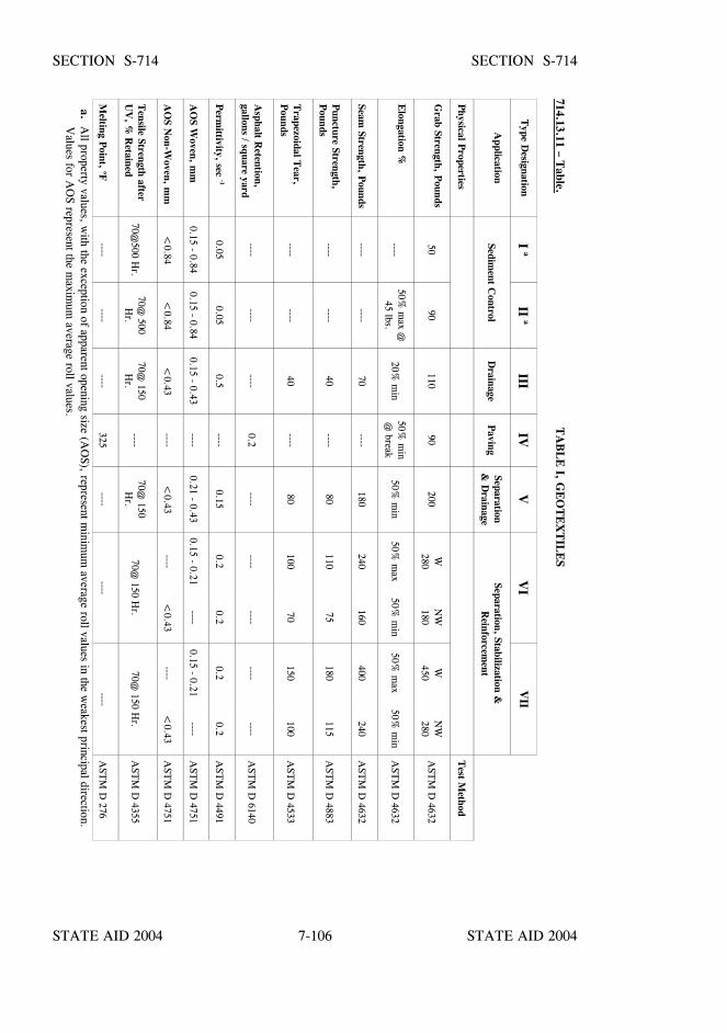
STATE AID 2004 STATE AID 2004
STATE AID 2004 STATE AID 20047-106
SECTION S-714 SECTION S-714
714.13.11 – Table.
TA
BL
E I, G
EO
TE
XT
ILE
S
Type D
esignationI a
II aIII
IVV
VI
VII
Application
Sediment C
ontrolD
rainageP
avingSeparation&
Drainage
Separation, Stabilization &R
einforcement
Physical P
ropertiesT
est Method
Grab Strength, P
ounds50
90110
90200
W280N
W180
W450N
W280
AST
M D
4632
Elongation %
----50%
max @
45 lbs.20%
min
50% m
in@
break50%
min
50% m
ax50%
min
50% m
ax50%
min
AST
M D
4632
Seam Strength, P
ounds----
----70
----180
240160
400240
AST
M D
4632
Puncture Strength,
Pounds
--------
40----
80110
75180
115A
STM
D 4883
Trapezoidal T
ear,P
ounds----
----40
----80
10070
150100
AST
M D
4533
Asphalt R
etention,gallons / square yard
--------
----0.2
--------
--------
----A
STM
D 6140
Perm
ittivity, sec -10.05
0.050.5
----0.15
0.20.2
0.20.2
AST
M D
4491
AO
S Woven, m
m0.15 - 0.84
0.15 - 0.840.15 - 0.43
----0.21 - 0.43
0.15 - 0.21----
0.15 - 0.21----
AST
M D
4751
AO
S Non-W
oven, mm
<0.84
<0.84
<0.43
----<
0.43----
<0.43
----<
0.43A
STM
D 4751
Tensile Strength after
UV
, % R
etained70@
500 Hr.
70@ 500
Hr.
70@ 150
Hr.
----70@
150H
r.70@
150 Hr.
70@ 150 H
r.A
STM
D 4355
Melting P
oint, oF----
--------
325----
--------
AST
M D
276
a. All property values, w
ith the exception of apparent opening size (AO
S), represent minim
um average roll values in the w
eakest principal direction. V
alues for AO
S represent the maxim
um average roll values.
STATE AID 2004 STATE AID 2004
STATE AID 2004 STATE AID 20047-107
SECTION S-715 - ROADSIDE DEVELOPMENT MATERIALS
S-715.01--Topsoil.
S-715.01.1--General. Topsoil shall be a well-graded soil of good uniform quality,without detrimental admixture of subsoil, refuse, or foreign material and reasonably freeof hard clods, stones, cement, brick, slag, concrete, sticks, or other undesirable materialharmful to plant life.
S-715.01.2--Material to be Obtained from the Right-of-Way. Topsoil for slopetreatment shall meet the general requirements as stated above and shall have apH value of not less than 4.5 nor more than 8.0.
S-715.01.3--Material to be Furnished by the Contractor. Topsoil for slope treatmentshall meet the general requirements of S-715.01.1, shall have a pH value of not less than4.5 nor more than 8.0, and shall be classified as a group A-4 or A-6 soil with minimumPI of 6.0 as specified by AASHTO Designation: M 145.
S-715.01.4--Sampling and Testing. Sampling and testing of topsoil shall be as set outin S-700.03.
S-715.02--Fertilizers.
S-715.02.1--General. Fertilizers shall comply with the fertilizer laws of the State ofMississippi.
S-715.02.2--Commercial Combination or Manufactured Fertilizer. Combination ormanufactured fertilizer shall be "standard commercial products" and shall contain not lessthan the percentages by weight of the ingredients set out in Table A, except foragricultural limestone which shall meet the requirements of S-715.02.2.1.

STATE AID 2004 STATE AID 2004
STATE AID 2004 STATE AID 20047-108
SECTION S-715 SECTION S-715
TA
BL
E A
TY
PES O
F F
ER
TIL
IZE
RS
CO
MB
INA
TIO
NM
AN
UF
AC
TU
RE
D
* 1018
615
128
013
SuperPhosphat
e
Am
monium
Nitrate
Urea
Muriate
Potash
Ureaform
1046
810
2424
2013
100
810
1224
2013
CH
EM
ICA
L C
OM
PO
NE
NT
S
Nitrogen
* 1018
615
128
012
3345
38
Phosphorous P2 O
510
468
1024
2420
1320
Potash K2 O
100
810
1224
2013
60
*Ureaform
(38-0-0) – This fertilizer shall contain a m
inimum
of 38% total nitrogen, 27%
of which shall be insoluble nitrogen
derived from ureaform
. The final m
ixture shall have a minim
um activity index (A
I) of 50% as determ
ined by the appropriateA
OA
C procedure.
*Ureaform
(10-10-10) – This fertilizer shall contain a m
inimum
of 10% total nitrogen, 35%
of which shall be insoluble
nitrogen derived from ureaform
. The final m
ixture shall have a minim
um activity index (A
I) of 40% as determ
ined by theappropriate A
OA
C procedure.
STATE AID 2004 STATE AID 2004
STATE AID 2004 STATE AID 20047-109
SECTION S-715 SECTION S-715
S-715.02.2.1– Agricultural Limestone. Agricultural limestone shall be either a Grade“A” liming material, or a marl or chalk agricultural liming material as addressed in thelatest Mississippi Agricultural Liming Material Act of 1993, published by the MississippiDepartment of Agriculture and Commerce. S-715-02.2.1.1--Screening Requirements. Grade “A” liming material, including groundshells, shall not have less than 90% of the material passing the No. 10 sieve, and not lessthan 50% passing the No. 60 sieve. Marl or chalk lining material shall not have less than90% of the material passing the No. 10 sieve.
S-715-02.2.1.2--Neutralizing Values. Grade “A” liming material shall not have less than90% calcium and magnesium carbonate calculated as calcium carbonate equivalent whenexpressed on a dry weight basis. Marl or chalk liming material shall not have less than70% calcium and magnesium carbonate calculated as calcium carbonate equivalent whenexpressed on a dry weight basis.
S-715.02.3--Sampling and Testing. Sampling and testing of agricultural limestone shallbe in accordance with S-700.03. Labels on containers or attached thereto showing theguaranteed analysis of other fertilizers will be prima facie evidence as to conformity withthe specified requirements.
S-715.03--Seed.
S-715.03.1--General. All seeds shall comply with the seed law of the State of Mississippiand the current regulations duly promulgated thereunder. The seed shall be delivered inbags with certified tags or labels attached to each bag showing the name (kind andvariety), percent of germination and purity of the seed, and the percent of obnoxiousweeds and inert matter.
S-715.03.2--Germination and Purity Requirements. The requirements for germinationand purity shall be as set out in Table B:
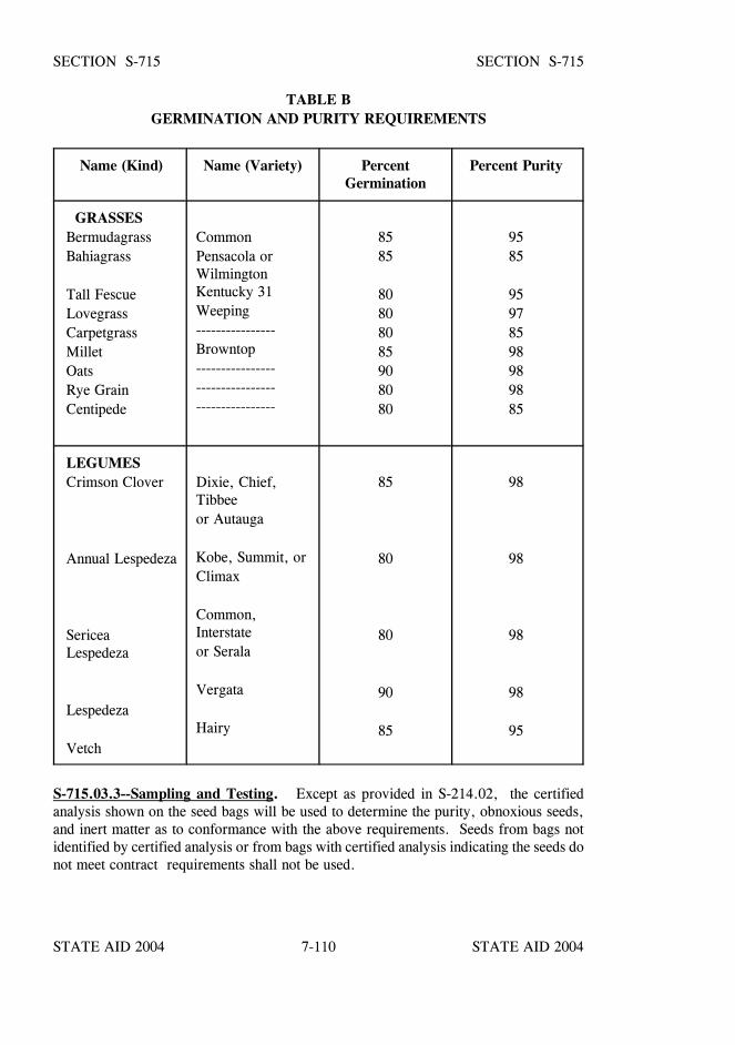
STATE AID 2004 STATE AID 2004
STATE AID 2004 STATE AID 20047-110
SECTION S-715 SECTION S-715
TABLE BGERMINATION AND PURITY REQUIREMENTS
Name (Kind) Name (Variety) PercentGermination
Percent Purity
GRASSESBermudagrassBahiagrass
Tall FescueLovegrassCarpetgrassMilletOatsRye GrainCentipede
CommonPensacola orWilmingtonKentucky 31Weeping----------------Browntop------------------------------------------------
8585
80808085908080
9585
95978598989885
LEGUMESCrimson Clover
Annual Lespedeza
SericeaLespedeza
Lespedeza
Vetch
Dixie, Chief,Tibbeeor Autauga
Kobe, Summit, orClimax
Common,Interstateor Serala
Vergata
Hairy
85
80
80
90
85
98
98
98
98
95
S-715.03.3--Sampling and Testing. Except as provided in S-214.02, the certifiedanalysis shown on the seed bags will be used to determine the purity, obnoxious seeds,and inert matter as to conformance with the above requirements. Seeds from bags notidentified by certified analysis or from bags with certified analysis indicating the seeds donot meet contract requirements shall not be used.
STATE AID 2004 STATE AID 2004
STATE AID 2004 STATE AID 20047-111
SECTION S-715 SECTION S-715
All seeds may be sampled and tested for percent germination, and the Engineerreserves the right to sample and test seeds for any required characteristic when deemedappropriate to do so as a check on the quality of the seeds; in which case the results ofsuch tests shall be the basis for acceptance, rejection, or adjustment under theprovisions of the contract.
Samples of seed to be tested will be taken by personnel under the supervision of theEngineer. The seeds will be sampled by means of a trier (probe) through the seed bags.A 1/4 pound sample will be required from each seed lot with equal quantities being takenfrom each sack within a lot to make up the sample.
S-715.03.4--Leguminous Inoculants. Approved legume seeds shall be treated withleguminous inoculant under the supervision of the Engineer. The inoculants for treatingleguminous seeds shall be standard, pure culture of nitrogen fixing bacteria. The seedshall be treated at the rate specified and according to the directions shown on the containerof the inoculants and before the expiration date for use of the inoculant as also shown onthe container.
S-715.04--Water. Water used in planting and establishment of vegetation shallcomply with the applicable requirements of S-714.01.
S-715.05--Vegetative Materials for Mulch. The vegetative materials for mulch shallbe classed as follows:
Type I. Approved baled straw of wheat, oat, rye grain, rice,broomsage or Bahia grass (with seed heads) which has reachedmaturity prior to cutting.
Type II. Approved baled hay produced from Bermuda, Bahia,Fescue, Dallis Grass, any of the Lespedezas, or combinations thereof.
All of the above materials shall have been properly cured prior to baling and shall bereasonably free from Johnson Grass and other obnoxious grasses and weeds. Vegetativematerial shall be reasonably bright in color, dry, and shall not be musty, moldy, or ofotherwise low quality. Vegetative material that is wet or that has been baled green (norcured properly) shall not be used.
Unless otherwise permitted in writing by the Engineer, Type I shall be furnished andused. The Engineer may permit the use of Type II when the Contractor has furnishedsatisfactory evidence in writing that Type I material is not available.
S-715.06--Blank.
STATE AID 2004 STATE AID 2004
STATE AID 2004 STATE AID 20047-112
SECTION S-715 SECTION S-715
S-715.07--Mulch for Woody Plant Materials. The mulch materials shall conform to thefollowing.
S-715.07.1--Tree Bark Mulch. The mulch shall be a standard manufactured product ofground, shredded, or broken particles from the bark of trees and shall be reasonably freeof weed seeds, harmful bacteria, or disease spores and substances toxic to plant growth. The mulch particles shall be of the following type(s), as specified in the contract:
Type I - Commonly known as extra coarse. Particle size shall be approximately oneinch to 2 1/2".
Type II - Commonly known as coarse. Particle size shall be approximately 1/2 inch toone inch.
Type III - Commonly known as medium. Particle size shall be approximately 1/4 inchto 1/2 inch.
Type IV - Commonly known as fine. Particle size shall be approximately 1/8 inch to 1/4inch.
All tree bark mulch shall be handled so as to insure proper protection againstcontamination at all times. The mulch shall be delivered to the job in unbroken bags orbales with a manufacturer's label or tag on each container. Labels or tags on thecontainers shall show the physical analysis of the contents, the size of the particles, andthe volume. Labels on containers or attached thereto showing the guaranteed analysis andvolume will be prima facie evidence of the materials meeting the above requirements. Allmulch will, however, be subject to approval by the Engineer as to quality and quantity.
S-715.07.2--Aggregate Mulch. Aggregate used as mulch shall be crushed or uncrushedgravel Size 5 or Size 56 meeting the gradation requirements of S-703.14 for coarseaggregate cover material.
S-715.07.3--Straw. Straw material for mulch shall be classed as follows:
Class I - Approved baled wheat, oat, rice or rye straw. The materials shall have beencured properly prior to baling and shall be reasonably free from obnoxious grasses andweeds. The straw material shall be reasonably bright in color, dry and shall not be musty,moldy, or of otherwise low quality.
Class II - Approved baled pine needles that is reasonably free of twigs, branches, andobnoxious grasses and weeds. The material shall be dry and shall not be musty, moldy,or of otherwise low quality. All straw mulch shall be inspected and approved by theEngineer prior to its use.
STATE AID 2004 STATE AID 2004
STATE AID 2004 STATE AID 20047-113
SECTION S-715 SECTION S-715
S-715.08--Fertilizer for Woody Plant Materials. The fertilizer material for woodyplants shall conform to the following requirements:
S-715.08.1--Fertilizer Packet. The fertilizer packet shall consist of an approvedmanufactured sealed polyethylene-paper laminated perforated packet containing one, two,or four ounces of water soluble fertilizer with a minimum guaranteed analysis of 16-8-16,16% Nitrogen, 8% Phosphoric Acid, 16% Potash.
S-715.08.2--Fertilizer Tablet. The fertilizer tablet shall consist of an approved tightlycompressed slow-release tablet 5, 10 or 21 gram size containing a minimum guaranteedanalysis of 20-10-5, 20% Nitrogen, 10% Phosphoric Acid, 5% Potash.
S-715.08.3--Guaranteed Analysis. Labels on containers or attached thereto showing theguaranteed analysis will be prima facie evidence of the fertilizer materials meeting thespecified requirements. All fertilizer packets and tablets will, however, be inspected andapproved by the Engineer or, at the Engineer’s discretion, may be sampled and tested.
S-715.09 - Ditch Liner Material. All ditch liner materials shall be new and free of ripsor tears.
S-715.09.1--Jute Mesh. Jute mesh shall be of uniform, plain weave with warp and weftyarns of approximately the same size. The physical requirements shall be:
Length 50 yards per roll, minimumWidth 48" plus or minus 1"Warp ends 78 per width, minimumWeft yarns 41 per yard, minimum
The weight of cloth Shall average 1.22 pounds per linear yard with a tolerance of plus10% or minus 5%.
S-715.09.2--Excelsior Blanket. Excelsior blanket shall consist of a machine-producedmat of interlocking wood excelsior with uniform thickness and the fiber evenly distributedover the entire area of the blanket. A fabric net of extruded plastic shall be applied toone side of the excelsior wood mat to hold the wood fibers in place.
The blankets shall not be exposed to moisture prior to placing.
STATE AID 2004 STATE AID 2004
STATE AID 2004 STATE AID 20047-114
SECTION S-715 SECTION S-715
The blanket shall meet the following requirements:
Interlocking Wood Fibers 0.02" x 0.04" (+ 25%)50% must be 3 1/2" or longer
Fabric Net 1 1/2" x 3 1/2" maximummesh size
Width 36" minimum
S-715.09.3--Erosion Control Blanket. The erosion control blanket shall consist of amachine-produced mat whose primary component is clean, weed-free straw from cerealgrain crops. The straw must be evenly distributed throughout the mat. The top side ofthe blanket shall be covered with a photodegradable plastic mesh having 3/4" x 3/4"maximum openings which shall be substantially adhered to the straw by a knitting processusing degradable thread. The blanket shall be supplied in a protective covering and shallmeet the following requirements:
Straw * 0.50 pounds per square yards minimum dry weightNetting Photodegradable plasticWidth 48-inch minimum
* Coconut fiber may be used to replace a portion or all of the straw.
S-715.09.4--Erosion Control Fabric. Erosion control fabric shall consist of a flexibleknitted construction of high strength degradable yarn with uniform openings interwovenwith strips of biodegradable paper and shall conform to the following requirements:
Width - 48 inches minimumWeight - 0.2 pound per square yard (approximate)
S-715.09.5--Wire Staples. The staples for securing the ditch liner material in place shallbe a double prong "U" configuration made from 11-guage or heavier steel wire with anapproximate length of six inches after bending.
S-715.09.6--Roving.
S-715.09.6.1--Polypropylene Roving. This material shall be formed from continuousstrands of fibrillated polypropylene yarn, collected into a rove. Fibrillation is defined asa net-like physical structure of the yarn created by splitting the yarn in a precise patternduring manufacture.
STATE AID 2004 STATE AID 2004
STATE AID 2004 STATE AID 20047-115
SECTION S-715 SECTION S-715
The polypropylene shall contain a sufficient amount of UV inhibitors so as to retain 70percent of its strength after 500 hours of exposure in an Atlas Twin Arc Weatherometer.
The fibrillated polypropylene roving shall have the following detailed requirements:
Property Limits Test Method
Strands / Rove 20-30 End CountYards per Pound of Rove 410-620 ASTM Designation: D 1907Package Weight, pounds 18 minimum ScaleColor Black
S-715.09.6.2--Fiberglass Roving. The material shall be formed from continuous fibersdrawn from molten glass, coated with a chromecomplex sizing compound, collected intostrands, and lightly bound together into a rove.
The fiberglass roving material shall meet the following detailed requirements:
Property Limits Test Method
Yield, yards per pound 170 - 300 ASTM Designation: D 578Fiber Diameter, inch 0.00035 - 0.00055 ASTM Designation: D 578Strands / Rove 50 - 70 End CountPackage Weight, pounds 25-50 Scale
S-715.09.7--Certification. The Contractor shall furnish the Engineer with three copiesof the manufacturer's certification for each shipment of ditch liner material stating theamount furnished and that the material complies with the requirements of thespecifications and also forward three copies of the manufacturer's or distributor'scertification showing the wire size for each shipment of staples.
The certifications by the manufacturer or distributor will be prima-facie evidence of thematerials meeting the specified requirements. All ditch liner material and staples will,however, be subject to approval by the Engineer.
STATE AID 2004 STATE AID 2004
STATE AID 2004 STATE AID 20047-116
SECTION S-716 - MISCELLANEOUS METALS
S-716.01--General. All miscellaneous metals shall be as shown on the plans or in thespecial provisions, and shall conform to the requirements as hereinafter set out, unlessotherwise specified.
Unless waived by the State Aid Engineer, the Contractor shall furnish the Engineer threecopies of certified test reports from an approved testing laboratory covering allmaterial described in this section.
S-716.02--Steel Castings.
S-716.02.1--Carbon Steel Castings. Carbon steel castings shall conform to AASHTODesignation: M 103. Grade 70-36 shall be furnished unless otherwise specified.
S-716.02.2--Chromium Alloy-Steel Castings. Chromium alloy-steel castings shallconform to ASTM Designation: A 743. Grade CA-15 shall be furnished unless otherwisespecified.
S-716.03--Steel Forgings. Steel forgings shall conform to AASHTO Designation:M 102. Class C forgings shall be furnished unless otherwise specified.
S-716.04--Gray Iron Castings. Gray iron castings shall conform to AASHTODesignation: M 105. Class 30B shall be furnished unless otherwise specified. Fortesting purposes a lot size shall be defined as the lesser of either a total of 35,000 poundsor one week's production for State/County projects. The test bar shall be made from amelt of iron used in production of units for the Project(s). The test bar length shall be aminimum of 16 inches.
S-716.05--Malleable Castings. Malleable castings shall conform to ASTM Designation:A 47. Grade No. 35018 shall be furnished unless otherwise specified.
S-716.06--Bronze Castings and Bearings. Bronze castings and bearings shall conformto AASHTO Designation: M 107. Alloy UNS No. C91100 shall be furnished unlessotherwise shown on the plans.
S-716.07--Copper Bearings and Sheet Copper.
S-716.07.1--Rolled Copper-Alloy Bearings and Expansion Plates. Rolled copper-alloybearings and expansion plates shall conform to AASHTO Designation: B 100 Alloy UNSNo. C51000 shall be furnished unless otherwise specified.
S-716.07.2--Sheet Copper. Sheet copper shall meet the requirements of AASHTODesignation: M 138 including the embrittlement test. The Copper No. shall be asdesignated on the plans.
STATE AID 2004 STATE AID 2004
STATE AID 2004 STATE AID 20047-117
SECTION S-716 SECTION S-716
S-716.08--Self-Lubricating Bearing Plates. Self-lubricating bearing plates shall be anarticle of standard production by an established manufacturer of such equipment. Theyshall be provided with trepanned or drilled recesses (not grooves) which shall be filledwith a lubricating compound capable of withstanding the atmospheric elements andconsisting of graphite and metallic substances with a lubricating binder. This compoundshall be pressed into the recesses by hydraulic presses so as to form dense nonplasticlubricating inserts. The lubricating area shall comprise not less than 25% nor more than35% of the total bearing area. Contractor shall furnish additional lubricating material instick form. Just prior to erecting the members which rest on the bronze plates, theContractor shall thoroughly rub the steel bearing plates, which rest on the bronze, withthe lubricant. These surfaces shall be unpainted and shall be cleaned with a steel brushimmediately before the lubricant is applied.
The bearing plates shall be made of (1) rolled bronze conforming to the requirements ofS-716.06 or (2) cast bronze conforming to requirements of S-716.05, Alloy UNS No.C91100 or No. C90500, except that a maximum lead content of 2.5% is allowable.
The coefficient of friction shall not exceed 0.10 when subjected to design loading and alsowhen subjected to twice the design loading.
Contact surfaces shall be finished in the direction of motion in accordance with therequirements of ANSI B46 1-55 No. 125. All machined surfaces shall be flat within0.0005 inch per inch of length and width. In mating curved surfaces of steel and bronze,the concave surfaces may have a plus tolerance of 0.01 inch and the convex surfaces,minus tolerance of 0.01 inch.
The Contractor shall furnish the manufacturer's shop drawings showing pattern and sizeof recesses.
S-716.09--Babbitt. Babbitt shall conform to ASTM Designation: B 23. The alloynumber shall be as designated on the plans.
S-716.10--Lead Plates, Pipes, Etc. Lead used for plates, pipes, etc. shall conform toASTM Designation: B 29 , Grade: Pure Lead.
S-716.11--Galvanized Pipe. Galvanized pipe for water, gas, etc., shall conform toASTM Designation: A 53.
S-716.12--Rolled Zinc. Rolled zinc shall conform to ASTM Designation: B 69. Thetype shall be as designated on the plans.
STATE AID 2004 STATE AID 2004
STATE AID 2004 STATE AID 20047-118
SECTION S-716 SECTION S-716
S-716.13--Electrical Conduit. Electrical conduit, including couplings, bends, andnipples, shall conform to Federal Specifications for Conduit, Electrical, Steel Rigid,Zinc-Coated.
S-716.14--Bar Grates.
S-716.14.1--Material Requirements. Plain round steel bars and strap bars shallconform to the following requirements:
B-9 Grates and Bar Grates: AASHTO Designation: M 270, Grade 36MI, GI, & SS-3 Grates: AASHTO Designation: M270, Grade 50W,
or ASTM Designation: A 588, Grade 50W
S-716.14.2--Fabrication and Finish. All bar grates shall be constructed in accordancewith the specifications and in conformity with the detailed plans.
Holes shall be punched or drilled in the strap bars to accommodate the round bars. Thejunctions of all round bars and/or strap bars shall be welded. The complete bar grate shallexhibit good workmanship.
After fabrication, the bar grate shall be coated with an approved commercial qualitycoating designed for coating steel castings and fabricated units. The Engineer shallapprove the coating material prior to application.
STATE AID 2004 STATE AID 2004
STATE AID 2004 STATE AID 20047-119
SECTION S-717 - STRUCTURAL STEEL
S-717.01--Structural Steel.
S-717.01.1--General. Steel shall be furnished according to the following specifications.Unless otherwise specified, structural carbon steel shall be furnished. Steels other thanthose required herein may be specified on the plans. When steel is used in weldedconstruction, the welding procedure shall be suitable for the steel and the intended service.
S-717.01.2--Requirements for Structural Steel. Structural steel shall meet theapplicable ASTM Standards which shall include the Supplementary Bend TestRequirement and the following Charpy V-Notch Requirements for minimum servicetemperature 0oF and above:
ASTMDESIGNATIONS
THICKNESS &FABRICATION
MINIMUM CHARPYV-NOTCH ENERGY@ TEMPERATURE
A 36*A 588*A 588*A 588*A 572*A 572*A 572 A 514 A 514 A 514 A 852 A 852 A 852
Up to 4"Up to 4" Mech. FastenedUp to 2" WeldedOver 2" to 4" WeldedUp to 4" Mech. FastenedUp to 2" WeldedOver 2" to 4" WeldedUp to 4" Mech. FastenedUp to 2 1/2" WeldedOver 2 1/2" to 4" WeldedUp to 4" Mech. FastenedUp to 2 1/2" WeldedOver 2 1/2" to 4" Welded
15 ft. lb. @ 70oF15 ft. lb. @ 70oF15 ft. lb. @ 70oF20 ft. lb. @ 70oF15 ft. lb. @ 70oF15 ft. lb. @ 70oF20 ft. lb. @ 70oF25 ft. lb. @ 30oF25 ft. lb. @ 30oF35 ft. lb. @ 30oF20 ft. lb. @ 50oF20 ft. lb. @ 50oF25 ft. lb. @ 50oF
* If the yield strength of the material exceeds 65 ksi, the temperature for the CVN valuefor acceptability shall be reduced 15oF for each increment, or fraction thereof, of 10 ksiabove 65 ksi.
The procedure for sampling and testing shall be in accordance with ASTM Designation:A 673. The (H) Frequency of Heat Testing shall be used for all the steel specificationsexcept ASTM Designation: A 514 which shall be in accordance with the (P) Frequencyof Piece Testing. If ASTM Designation: A 517 steel is used in lieu of A 514, thesampling and testing requirements shall be the same as the A 514 of equal thickness.
STATE AID 2004 STATE AID 2004
STATE AID 2004 STATE AID 20047-120
SECTION S-717 SECTION S-717
S-717.01.3--Structural Carbon Steel. Structural carbon steel for bolted and weldedconstruction shall be in accordance with ASTM Designation: A 36.
S-717.01.4--Eyebars. Steel for eyebars shall be a weldable grade. These grades includestructural steel conforming to:
(a) Structural Carbon Steel ASTM Designation: A 36.(b) High-Strength Low-Alloy Structural Steel with 50,000 psi,
minimum yield point to 4" thick, ASTM Designation: A 588 withsupplementary requirements for Charpy V-Notch mandatory.
S-717.01.5--High Strength Low-Alloy Structural Steel. High-Strength Low-AlloyStructural Steel shall conform to:
(a) High-Strength Low-Alloy Columbium-Vanadium Steels of StructuralQuality, ASTM Designation: A 572.
(b) High-Strength Low-Alloy Structural Steel with 50,000 psi,minimum yield point to 4" thick, ASTM Designation: A 588.
S-717.01.6--High Strength Low-Alloy Structural Steel for Welding. High StrengthLow- Alloy Structural Steel for welding shall conform to:
(a) High-Strength Low-Alloy Columbium-Vanadium Steels of StructuralQuality, ASTM Designation: A 572, Grade 50.
(b) High-Strength Low-Alloy Structural Steel with 50,000 psi,minimum yield point to 4" thick, ASTM Designation: A 588.
S-717.01.7--High Strength Structural Steel for Bolted Construction. High-StrengthStructural Steel for bolted construction shall conform to:
(a) High-Strength Low-Alloy Columbium-Vanadium Steels of StructuralQuality, ASTM Designation: A 572, Grade 50.
(b) High-Strength Low-Alloy Structural Steel with 50,000 psi,minimum yield point to 4" thick, ASTM Designation: A 588.
S-717.01.8--High-Yield-Strength, Quenched, and Tempered Alloy Steel Plate.High-Yield-Strength, Quenched and Tempered Alloy Steel Plate shall conform to:
(a) High-Yield Strength, Quenched and Tempered Alloy Steel Plate,suitable for welding, ASTM Designation: A 514
(b) High-Strength Alloy Steel Plates, Quenched and Tempered forpressure vessels, ASTM Designation: A 517.
STATE AID 2004 STATE AID 2004
STATE AID 2004 STATE AID 20047-121
SECTION S-717 SECTION S-717
S-717.01.9--Acceptance Procedure. Structural Steel shall be accepted on the basis ofmanufacturer's certified test reports. The Contractor shall furnish the Engineer withthree copies of the certified test reports.
S-717.02--Fasteners. Fasteners for structural steel joints shall conform to the ASTMspecifications with revisions, as specified herein.
S-717.02.1--Plain Finish Fasteners.
S-717.02.1.1-Bolts. Ungalvanized bolts shall meet the requirements of ASTMDesignation: A 325 or ASTM Designation: A 490, as specified on the plans.
S-717.02.1.2-Heavy Hex Nuts. Ungalvanized nuts shall meet the requirements of ASTMDesignation: A 194, Grade 2H, or A 563, Grade DH, as specified on the plans.
S-717.02.1.3--Hardened Washers. Ungalvanized washers shall meet the requirementsof ASTM Designation: F 436.
S-717.02.2--Galvanized Fasteners.
S-717.02.2.1--Galvanized Bolts. Bolts shall meet the requirements of ASTMDesignation: A 325, Type 1. Galvanizing shall be in accordance with ASTMDesignation: A 153, Class C, or ASTM Designation: B 695, Class 50. Thickness of zinccoating shall be measured on the wrench flats or top of bolt head.
S-717.02.2.2--Galvanized Nuts. Nuts shall meet the requirements of ASTMDesignation: A 563, Grade DH. Galvanizing shall be in accordance with ASTMDesignation: A 153, Class C, or ASTM Designation: B 695, Class 50. Thickness of zinccoating shall be measured on the wrench flats.
S-717.02.2.3--Galvanized Washers. Washers shall meet the requirements of ASTMDesignation: F 436. Galvanizing shall be in accordance with ASTM Designation:A 153, Class C, or ASTM Designation: B 695, Class 50.
S-717.02.2.4--Direct Tension Indicators. Direct tension indicators shall meet therequirements of ASTM Designation: F 959 and galvanized in accordance with ASTMDesignation: B 695, Class 50.
STATE AID 2004 STATE AID 2004
STATE AID 2004 STATE AID 20047-122
SECTION S-717 SECTION S-717
S-717.02.3--Revisions to ASTM Specifications.
S-717.02.3.1--ASTM Designation: A 325. Hardness for bolt diameters 1/2-inch to 1-inch inclusive shall have a minimum Rockwell C Hardness Number of 24 and a maximumRockwell C Hardness Number of 33.
S-717.02.3.2--ASTM Designation: A 563. Nuts that are to be galvanized shall betapped oversize the minimum amount required for proper assembly. The amount ofovertap in the nut shall be such that the nut will assemble freely on the bolt in the coatedcondition and shall meet the rotational-capacity test set out in S-717.02.3.4.
The overtapping requirements of ASTM Designation: A 563, Subsection 7.4, shall beconsidered maximum values instead of minimum, as currently shown.
Galvanized nuts shall be lubricated with a lubricant containing a dye of any color thatcontrasts with the color of the galvanizing.
S-717.02.3.3--ASTM Designation: F 606.
S-717.02.3.3.1--Bolts. Proof load tests shall be performed in accordance with Method1, Length Measurement. Minimum frequency of tests shall be as specified in ASTMDesignation: A 325 for "Production Lot Method." Wedge tests on full size bolts arerequired. If bolts are to be galvanized, the tests shall be performed after galvanizing.Minimum frequency of tests shall be as specified in ASTM Designation: A 325,"Production Lot Method."
S-717.02.3.3.2--Nuts. Proof load tests shall be performed in accordance with ASTMDesignation: F 606, Subsection 4.2. If nuts are to be galvanized, tests shall beperformed after galvanizing, overtapping and lubricating.
S-717.02.3.3.3--Washers. If galvanized washers are supplied, hardness testing shall beperformed after galvanizing. The coating shall be removed prior to taking hardnessmeasurements.
S-717.02.3.4--Rotational-Capacity Testing of Assemblies. Rotational-capacity tests arerequired and shall be performed on all black or galvanized (after galvanizing) bolt, nutand washer assemblies by the manufacturer or distributor prior to shipping. Washers arerequired as part of the test even though they may not be required as part of theinstallation procedure. Except as modified herein, the rotational-capacity test shall beperformed in accordance with the requirements of ASTM Designation: A 325. Thefollowing shall apply:
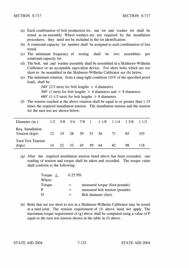
STATE AID 2004 STATE AID 2004
STATE AID 2004 STATE AID 20047-123
SECTION S-717 SECTION S-717
(a) Each combination of bolt production lot, nut lot and washer lot shall betested as an assembly. Where washers are not required by the installationprocedures, they need not be included in the lot identification.
(b) A rotational-capacity lot number shall be assigned to each combination of lotstested.
(c) The minimum frequency of testing shall be two assemblies perrotational-capacity lot.
(d) The bolt, nut and washer assembly shall be assembled in a Skidmore-WilhelmCalibrator or an acceptable equivalent device. For short bolts which are tooshort to be assembled in the Skidmore-Wilhelm Calibrator see (h) below.
(e) The minimum rotation, from a snug tight condition (10% of the specified proofload), shall be:
240o (2/3 turn) for bolt lengths < 4 diameters360o (1 turn) for bolt lengths > 4 diameters and < 8 diameters480o (1-1/3 turn) for bolt lengths > 8 diameters
(f) The tension reached at the above rotation shall be equal to or greater than 1.15times the required installation tension. The installation tension and the tensionfor the turn test are shown below:
Diameter (in.) 1/2 5/8 3/4 7/8 1 1 1/8 1 1/4 1 3/8 1 1/2
Req. InstallationTension (kips) 12 19 28 39 51 56 71 85 103
Turn Test Tension(kips) 14 22 32 45 59 64 82 98 118
(g) After the required installation tension listed above has been exceeded, onereading of tension and torque shall be taken and recorded. The torque valueshall conform to the following:
Torque < 0.25 PDWhere:Torque = measured torque (foot-pounds)P = measured bolt tension (pounds)D = Bolt diameter (feet)
(h) Bolts that are too short to test in a Skidmore-Wilhelm Calibrator may be testedin a steel joint. The tension requirement of (f) above need not apply. Themaximum torque requirement of (g) above shall be computed using a value of Pequal to the turn test tension shown in the table in (f) above.
STATE AID 2004 STATE AID 2004
STATE AID 2004 STATE AID 20047-124
SECTION S-717 SECTION S-717
S-717.02.4--Reporting. The results of all tests (including zinc coating thickness)required herein and in the appropriate ASTM specifications shall be recorded on theappropriate document. Location where tests are performed and date of tests shall bereported on the appropriate document. The manufacturer or distributor that performs thetest shall certify that the results recorded are accurate. The manufacturer shall certifythat the steel and the assembly components are domestic products.
S-717.02.5--Documentation.
S-717.02.5.1--Mill Test Report(s) (MTR). MTR shall be furnished for all mill steelused in the manufacture of the bolts, nuts, and washers. MTR shall indicate the placewhere the material was melted and manufactured.
S-717.02.5.2--Manufacturer Certified Test Report(s) (MCTR). The manufacturer ofthe bolts, nuts, and washers shall furnish the Office of State Aid Road Construction threecopies of test reports (MCTR) for the items furnished. Each MCTR shall have theappropriate MTR attached. Each MCTR shall contain the information required inS-717.02.4.
The manufacturer performing the rotational-capacity test shall include on the MCTR thefollowing:
(a) The lot number of each of the items tested.(b) The rotational-capacity lot number as required in paragraph (b) of S-717.02.3.4.(c) The results of the tests required in S-717.02.3.4.(d) The pertinent information required in S-717.02.4.(e) A statement that MCTR for the items are in conformance to this specification and
the appropriate ASTM specifications.(f) The location where the bolt assembly components were manufactured.
S-717.02.5.3--Distributor Certified Test Report(s) (DCTR). The following shall beapplicable for DCTR:
(a) The DCTR shall include MCTR above the various bolt assembly components.(b) The rotational-capacity test may be performed by a distributor (in lieu of a
manufacturer) and reported on the DCTR.(c) The DCTR shall show the results of the tests required in S-717.02.3.4.(d) The DCTR shall also show the pertinent information required in S-717.02.4.(e) The DCTR shall show the rotational-capacity lot number as required in
paragraph (b) of S-717.02.3.4.(f) The DCTR shall certify that the MCTR are in conformance to this specification
and the appropriate ASTM specifications.
STATE AID 2004 STATE AID 2004
STATE AID 2004 STATE AID 20047-125
SECTION S-717 SECTION S-717
S-717.02.6--Shipping. Bolts, nuts and washers (where required) from eachrotational-capacity lot shall be shipped in the same container. If there is only oneproduction lot number for each size of nut and washer, the nuts and washers may beshipped in separate containers. Each container shall be permanently marked with therotational-capacity lot number such that identification will be possible at any stage priorto installation. Three copies of the appropriate MTR, MCTR or DCTR shall be furnishedto the Engineer.
S-717.02.7--Final Acceptance. Final acceptance of high strength bolts, nuts,washers and direct tension indicators will be based on tests performed on samplesobtained from the project by the Engineer. Tests will be performed in accordance withthe procedures set out in these specifications. A lot shall be defined as each shipment toa project from the manufacturer's lot number and of the same size and length. Theintegrity of each lot shall be maintained until tests are completed by the MDOT.
Each lot of bolts, shall be sampled as follows:
Lot Size150 or less151 to 280281 to 500501 to 12001201 to 3200
3201 to 10,00010,001 and over
Sample Size24610162640
Note: One-half of the sampled bolts will be used for tensile testing and the other one-half will be tested for coating and/or hardness.
Each lot of nuts or washers, shall be sampled as follows:
Lot Size800 or less801 to 8000
8001 to 22,00022,001 and over
Sample Size1235
Note: The sample size shall be doubled when galvanized nuts or washers are specified or used.
STATE AID 2004 STATE AID 2004
STATE AID 2004 STATE AID 20047-126
SECTION S-717 SECTION S-717
Each lot of direct tension indicators shall be sampled as follows:
Lot Size35,000 or less
35,001 to 250,000250,001 and over
Sample Size162632
Direct tension indicators shall be tested in accordance with ASTM Designation: F 959.One-half of the samples will be tested in compression and the remaining one-half will betested for coating.
S-717.03--Copper Bearing Steels. When copper bearing steel is specified, the steelshall contain not less than 0.2 percent copper.
S-717.04--Welded Stud Shear Connectors.
(a) Shear connector studs shall conform to the requirements of Cold Finished CarbonSteel Bars and Shafting, ASTM Designation: A 108 Cold-Drawn Bars, Grades1015, 1018, or 1020, either semi or fully killed. If flux retaining caps are used,the steel for caps shall be of a low carbon grade suitable for welding and shallcomply with Cold-Rolled Carbon Steel Strip, ASTM Designation: A 109.
(b) Tensile properties as determined by tests of bar stock after drawing or of finishedstuds shall conform to the following requirements:
Tensile Strength (min.) 60,000 psiYield Strength* (min.) 50,000 psiElongation (min.) 20% in 2 inchesReduction of area (min.) 50%
*As determined by a 0.2 percent offset method.
(c) Tensile properties shall be determined in accordance with the applicable sectionsof ASTM Designation: A 370, Mechanical Testing of Steel Products. Tensiletests of finished studs shall be made on studs welded to test plates. If fractureoccurs outside of the middle half of the gage length, the test shall be repeated.
STATE AID 2004 STATE AID 2004
STATE AID 2004 STATE AID 20047-127
SECTION S-717 SECTION S-717
(d) Finished studs shall be uniform quality and condition, free from injurious laps,fins, seams, cracks, twists, bends, or other injurious defects. Finish shall be asproduced by cold drawing, cold rolling, or machining.
(e) The manufacturer shall certify that the studs delivered are in accordance with thematerial requirements of this section. Certified copies of in-plant quality controltest reports shall be furnished to the Engineer upon request.
(f) The Engineer may select, at the Contractor's expense, studs of each type and sizeused under the contract, as necessary for checking the requirements of thissection.
S-717.05--Steel Grid Flooring.
S-717.05.1--Steel. All steel shall conform to the Specification for Structural Steel of theASTM Designation: A 36, ASTM Designation: A 572, Grade 50, or ASTMDesignation: A 588. Unless the material is galvanized, it shall have a copper content of0.2 percent.
S-717.06--Pins and Rollers. Steel for pins and rollers shall conform to the designationslisted in Tables I and II below. Pins and rollers shall be accurately turned to thedimensions shown on the drawings and shall be straight, smooth, and free from flaws.Pins and rollers more than nine inches in diameter shall be forged rollers and annealed.Pins and rollers nine inches or less in diameter may be either forged and annealed orcold-finished carbon-steel shafting.
In pins larger than nine inches in diameter, a hole not less than two inches in diametershall be bored full length along the axis after the forging has been allowed to cool to atemperature below the critical range, under suitable conditions to prevent injury by toorapid cooling, and before being annealed.

STATE AID 2004 STATE AID 2004
STATE AID 2004 STATE AID 20047-128
SECTION S-717 SECTION S-717
TA
BL
E I
Minim
um M
aterial Properties
Structural Steel
Type
StructuralC
arbonSteel
High Strength
Low
-Alloy Steel
High Y
ield StrengthQ
uenched and Tem
peredA
lloy and Low
Alloy
Steel
Designation
AST
MA
36A
572G
rade 50A
588A
514/A 517
Thickness of Plates
Up to and including
8 inches.U
p to and including4 inches.
Up to and including
4 inchesO
ver 2-1/2 inches up toand including 4 inches
Minim
um T
ensileStrength, F
u (psi)58,000
65,00070,000
100,000
Minim
um Y
ieldPointor M
inimum
Yield
Strength, Fy (psi)
36,00050,000
50,00090,000
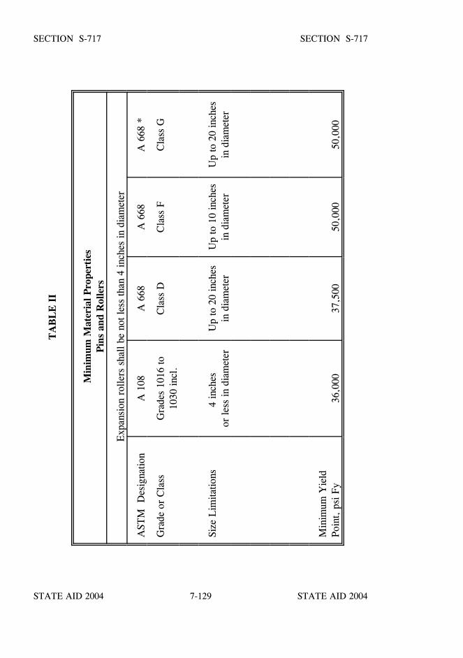
STATE AID 2004 STATE AID 2004
STATE AID 2004 STATE AID 20047-129
SECTION S-717 SECTION S-717T
AB
LE
II
Min
imum
Mat
eria
l Pro
pert
ies
Pin
s an
d R
olle
rs
Exp
ansi
on r
olle
rs s
hall
be n
ot le
ss th
an 4
inch
es in
dia
met
er
AST
M D
esig
natio
nA
108
A 6
68A
668
A 6
68 *
Gra
de o
r C
lass
Gra
des
1016
to10
30 in
cl.
Cla
ss D
Cla
ss F
Cla
ss G
Size
Lim
itatio
ns4
inch
es
or le
ss in
dia
met
erU
p to
20
inch
esin
dia
met
erU
p to
10
inch
esin
dia
met
erU
p to
20
inch
esin
dia
met
er
Min
imum
Yie
ldPo
int,
psi
Fy
36,0
0037
,500
50,0
0050
,000
STATE AID 2004 STATE AID 2004
STATE AID 2004 STATE AID 20047-130
SECTION S-718 - TIMBER AND DIMENSION LUMBER
S-718.01--Timber and Dimension Lumber. General. All timber and dimension lumbershall be Southern pine and shall conform in all respects to applicable requirements ofAASHTO Designation: M 168. Inspection for conformance to these specifications will beconducted in accordance with the SOP.
Timber and dimension lumber shall be furnished in the sizes shown on the plans or asspecified. Unless otherwise specified, timber and dimension lumber shall be No. 1 SR,graded according to American Lumber Standards.
Only one type of preservative shall be used for the treatment of materials for any one classof construction on a project, unless otherwise specified.
S-718.02--Untreated Timber and Dimension Lumber. Untreated timber and dimensionlumber shall comply with the requirements set out in S-718.01.
S-718.03--Treated Timber and Dimension Lumber. Timber and dimension lumber tobe treated shall meet the requirements herein specified and shall be treated by a pressuremethod to the minimum required retainage of preservative as specified on the plans orelsewhere in the specifications. Treated timber or dimensional lumber will be subject toinspection by the Engineer both before and after treatment. Inspection prior to treatmentmay be waived by the Engineer when the preservative will be pentachlorophenol orchromated copper arsenate. The Contractor shall furnish three copies of themanufacture’s certification that the material complies with the requirements as specified.
S-718.03.1--Seasoning. Seasoning timber, dimension lumber, piles and poles to betreated with preservatives shall conform to the requirements of AWPA.
S-718.03.2--Treatment.
S-718.03.2.1--General. Insofar as practicable, each charge shall consist of piecesapproximately equal in size, moisture, and sapwood content into which approximatelyequal quantities of preservative can be injected. Each layer of material shall be separatedat each end, and at the center when necessary, by strips at least 3/8 inch in thickness;caps, stringers, and other large timbers shall be separated by strips of at least 1/2 inchthickness.
All timber and lumber shall be treated in accordance with AWPA treating practices unlessotherwise specified herein.
Unless otherwise directed, the type and minimum quantity of preservative shall be inaccordance with TABLES 1, 2 or 3.
STATE AID 2004 STATE AID 2004
STATE AID 2004 STATE AID 20047-131
SECTION S-718 SECTION S-718
Any treated timber or lumber to be painted shall be treated in accordance with S-718.04.3,Type B solvent, or S-718.04.4.
Brackish water, as listed in TABLES l, 2 or 3, shall mean salt waters, bordering land, andwaters adjacent thereto which are subject to tidal flow.
S-718.03.2.2--Penetration. Unless otherwise specified, treated timber and lumber shallshow a 100 percent sapwood penetration or a minimum penetration of four inches.
The test method for determining the amount of preservative retained will be either asspecified in AWPA or Mississippi Test Methods. The borer cores shall be obtained inaccordance with AWPA Standard M2 and shall be taken from pieces having a sapwooddepth at least equal to the sampling zone specified as follows:
(a) Round Units (piling and poles) shall be in accordance withAWPA requirements.
(b) Structural members less than four inches shall be from zero toone and one half inches from the surface.
(c) All other structural members shall be from zero to two inchesfrom the surface.
S-718.03.2.3--Inspection. The Engineer shall be notified sufficiently in advance oftreating the material so that an inspector may be furnished at the plant to inspect thematerial and the treatment of same. All materials and processes used in the manufactureof the material shall be subject to inspection. The plant shall be equipped with thenecessary gauges, thermometers, appliances, and facilities to enable the inspector todetermine the conditions at all stages of the treatment and to satisfy himself that therequirements of the specifications are fulfilled. The manufacturer shall also provide theapparatus and chemicals necessary for making tests at the plant as required by thesespecifications. All equipment, apparatus, etc., shall be maintained in proper andsatisfactory condition for use at all times.
Tests for penetration of preservative shall be made with an increment borer. Test holesshall be plugged with treated plugs. All borings shall be taken at the center of the narrowside of the piece. Sufficient borings shall be taken to insure that the specified penetrationhas been obtained, with a minimum of 20 borings required for each charge of materials.

STATE AID 2004 STATE AID 2004
STATE AID 2004 STATE AID 20047-132
SECTION S-718 SECTION S-718
If 20% or more of the borings from a charge of treated material fail to meet thepenetration requirements, the entire charge shall be rejected and subject to retreatment.If upon retreatment, the material meets the penetration requirements, it will be accepted.Only one retreatment will be permitted, and any apparent damage due to retreatment shallbe cause for rejection.
S-718.03.3--Handling Treated Material. Any bruising or rough handling will be causefor rejection.
S-718.03.4--Storage of Treated Material. All material treated for stock shall be stackedas compactly as possible on a well-drained surface. Material shall be supported on sillsspaced as necessary, not to exceed 10 foot intervals and shall have at least one foot of airspace beneath the stacks.
All materials treated with CCA for use in buildings and applications where painting isrequired shall be dried after treatment. The treated wood shall be kiln dried by AmericanLumber Standards, or air dried for a period of at least 21 days before shipment.
S-718.04--Preservative. The preservatives shall meet the applicable requirements ofAWPA and the following:
The water content in an oil preservative shall not exceed 3.0% unless otherwise approvedby the Engineer: in no case shall it exceed 5.0%.
S-718.04.1--Creosote Oil. The creosote oil shall meet the requirements of AWPA P-1.The test methods shall be either AWPA or Mississippi Test Methods.
S-718.04.2--Creosote-Coal Tar Solution. The creosote coal tar solution shall meet therequirements of AWPA P-2. The test methods shall be either AWPA or Mississippi TestMethods.
S-718.04.3--Pentachlorophenol. The pentachlorophenol shall meet the requirements ofAWPA P-8. The test methods shall be either AWPA or Mississippi Test Methods.
The hydrocarbon solvent used in the pentachlorophenol solution shall meet therequirements of AWPA P-9, Type A or B. When painting is required, Type B solventshall be used. Type A solvent shall be used for all other treatment unless otherwisespecified.
S-718.04.4--Chromated Copper Arsenate (CCA). The solution shall contain a sufficientconcentration of the water-born preservative to produce the minimum specified retention.The preservative shall meet the requirements of AWPA P-5, CCA Type B or C. The testmethods shall be either AWPA or Mississippi Test Methods.
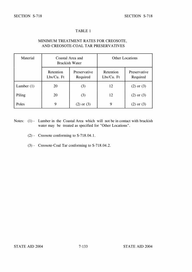
STATE AID 2004 STATE AID 2004
STATE AID 2004 STATE AID 20047-133
SECTION S-718 SECTION S-718
TABLE 1
MINIMUM TREATMENT RATES FOR CREOSOTE, AND CREOSOTE-COAL TAR PRESERVATIVES
Material Coastal Area andBrackish Water
Other Locations
RetentionLbs/Cu. Ft
PreservativeRequired
RetentionLbs/Cu. Ft
PreservativeRequired
Lumber (1) 20 (3) 12 (2) or (3)
Piling 20 (3) 12 (2) or (3)
Poles 9 (2) or (3) 9 (2) or (3)
Notes: (1) - Lumber in the Coastal Area which will not be in contact with brackishwater may be treated as specified for "Other Locations".
(2) - Creosote conforming to S-718.04.1.
(3) - Creosote-Coal Tar conforming to S-718.04.2.
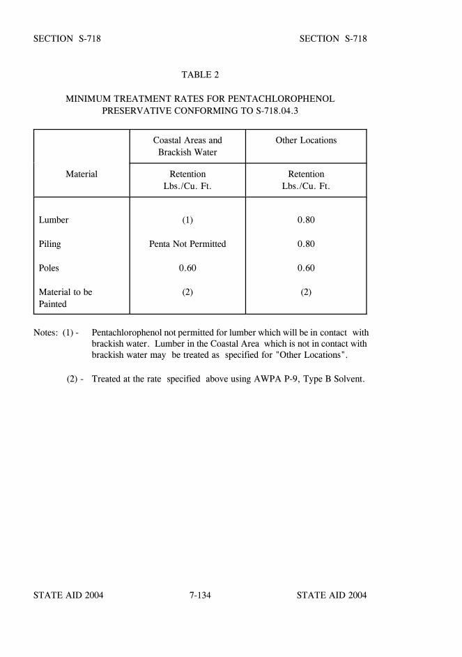
STATE AID 2004 STATE AID 2004
STATE AID 2004 STATE AID 20047-134
SECTION S-718 SECTION S-718
TABLE 2
MINIMUM TREATMENT RATES FOR PENTACHLOROPHENOLPRESERVATIVE CONFORMING TO S-718.04.3
Coastal Areas andBrackish Water
Other Locations
Material RetentionLbs./Cu. Ft.
RetentionLbs./Cu. Ft.
Lumber
Piling
Poles
Material to bePainted
(1)
Penta Not Permitted
0.60
(2)
0.80
0.80
0.60
(2)
Notes: (1) - Pentachlorophenol not permitted for lumber which will be in contact withbrackish water. Lumber in the Coastal Area which is not in contact withbrackish water may be treated as specified for "Other Locations".
(2) - Treated at the rate specified above using AWPA P-9, Type B Solvent.
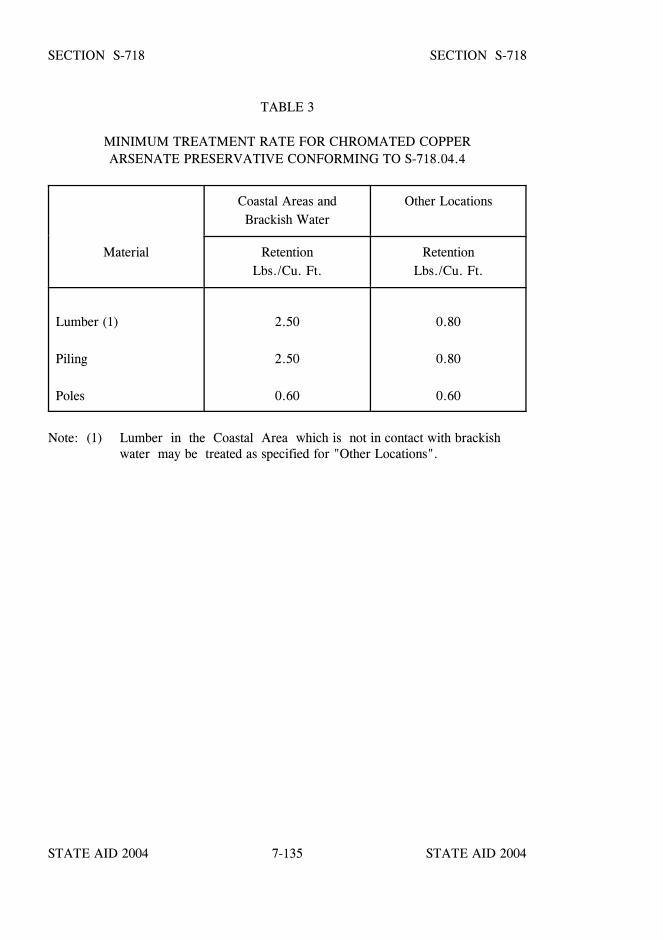
STATE AID 2004 STATE AID 2004
STATE AID 2004 STATE AID 20047-135
SECTION S-718 SECTION S-718
TABLE 3
MINIMUM TREATMENT RATE FOR CHROMATED COPPERARSENATE PRESERVATIVE CONFORMING TO S-718.04.4
Coastal Areas andBrackish Water
Other Locations
Material RetentionLbs./Cu. Ft.
RetentionLbs./Cu. Ft.
Lumber (1)
Piling
Poles
2.50
2.50
0.60
0.80
0.80
0.60
Note: (1) Lumber in the Coastal Area which is not in contact with brackishwater may be treated as specified for "Other Locations".
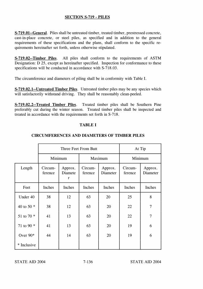
STATE AID 2004 STATE AID 2004
STATE AID 2004 STATE AID 20047-136
SECTION S-719 - PILES
S-719.01--General. Piles shall be untreated timber, treated timber, prestressed concrete,cast-in-place concrete, or steel piles, as specified and in addition to the generalrequirements of these specifications and the plans, shall conform to the specific re-quirements hereinafter set forth, unless otherwise stipulated.
S-719.02--Timber Piles. All piles shall conform to the requirements of ASTMDesignation: D 25, except as hereinafter specified. Inspection for conformance to thesespecifications will be conducted in accordance with S-718.03.
The circumference and diameters of piling shall be in conformity with Table I.
S-719.02.1--Untreated Timber Piles. Untreated timber piles may be any species whichwill satisfactorily withstand driving. They shall be reasonably clean-peeled.
S-719.02.2--Treated Timber Piles. Treated timber piles shall be Southern Pinepreferably cut during the winter season. Treated timber piles shall be inspected andtreated in accordance with the requirements set forth in S-718.
TABLE I
CIRCUMFERENCES AND DIAMETERS OF TIMBER PILES
Three Feet From Butt At Tip
Minimum Maximum Minimum
Length Circum-ference
Approx.Diamete
r
Circum-ference
Approx.Diameter
Circum-ference
Approx.Diameter
Feet Inches Inches Inches Inches Inches Inches
Under 40 38 12 63 20 25 8
40 to 50 * 38 12 63 20 22 7
51 to 70 * 41 13 63 20 22 7
71 to 90 * 41 13 63 20 19 6
Over 90* 44 14 63 20 19 6
* Inclusive
STATE AID 2004 STATE AID 2004
STATE AID 2004 STATE AID 20047-137
SECTION S-719 SECTION S-719
S-719.03--Concrete Piles. Concrete piles, both prestressed and cast-in-place, shall beconstructed in conformity with the plans and in accordance with thesespecifications. Additional requirements for prestressed piles are set out in S-803.
All concrete materials and their preparation and placing shall be in accordance with therequirements of the class of concrete specified and in accordance with S-803.
Reinforcing steel shall conform to the requirements of S-711.
S-719.04--Steel Piles. The material in rolled steel piles shall be standard structural gradesteel of the section number, size, and weight per linear foot indicated on the plans. Thesteel shall conform to the requirements of ASTM Designation: A 36.
The Contractor shall furnish the Engineer three certified copies of the mill test reportscontaining the true chemical and physical analyses of the material.
S-719.05--Steel Sheet Piling. Steel sheet piling shall conform to the requirements ofASTM Designation: A 328.
The Contractor shall furnish the Engineer with three certified copies of the mill testreports containing the true chemical and physical analyses of the material.
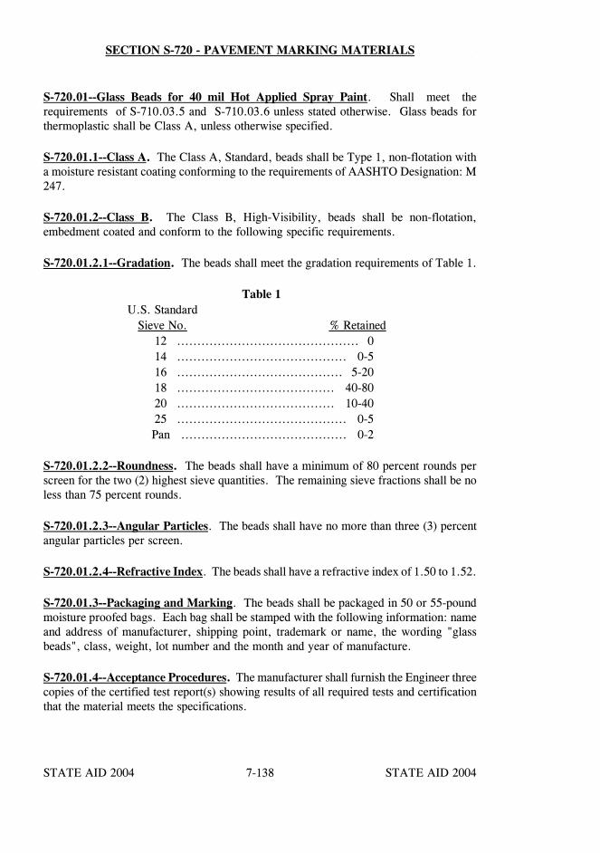
STATE AID 2004 STATE AID 2004
STATE AID 2004 STATE AID 20047-138
SECTION S-720 - PAVEMENT MARKING MATERIALS
S-720.01--Glass Beads for 40 mil Hot Applied Spray Paint. Shall meet therequirements of S-710.03.5 and S-710.03.6 unless stated otherwise. Glass beads forthermoplastic shall be Class A, unless otherwise specified.
S-720.01.1--Class A. The Class A, Standard, beads shall be Type 1, non-flotation witha moisture resistant coating conforming to the requirements of AASHTO Designation: M247.
S-720.01.2--Class B. The Class B, High-Visibility, beads shall be non-flotation,embedment coated and conform to the following specific requirements.
S-720.01.2.1--Gradation. The beads shall meet the gradation requirements of Table 1.
Table 1U.S. Standard
Sieve No. % Retained12 ............................................. 014 .......................................... 0-516 ......................................... 5-2018 ....................................... 40-8020 ....................................... 10-4025 .......................................... 0-5Pan ......................................... 0-2
S-720.01.2.2--Roundness. The beads shall have a minimum of 80 percent rounds perscreen for the two (2) highest sieve quantities. The remaining sieve fractions shall be noless than 75 percent rounds.
S-720.01.2.3--Angular Particles. The beads shall have no more than three (3) percentangular particles per screen.
S-720.01.2.4--Refractive Index. The beads shall have a refractive index of 1.50 to 1.52.
S-720.01.3--Packaging and Marking. The beads shall be packaged in 50 or 55-poundmoisture proofed bags. Each bag shall be stamped with the following information: nameand address of manufacturer, shipping point, trademark or name, the wording "glassbeads", class, weight, lot number and the month and year of manufacture.
S-720.01.4--Acceptance Procedures. The manufacturer shall furnish the Engineer threecopies of the certified test report(s) showing results of all required tests and certificationthat the material meets the specifications.

STATE AID 2004 STATE AID 2004
STATE AID 2004 STATE AID 20047-139
SECTION S-720 SECTION S-720
S-720.02--Temporary Raised Pavement Markers.
S-720.02.1--Material Requirements:
A. The temporary raised markers shall be flexible reflective tabs. Themarkers shall be yellow with amber reflective area on both sides. Thebody of the marker shall consist of a base and vertical wall made ofpolyurethane or other approved material and shall be capable ofmaintaining a reasonable vertical position after installation. The initialminimum reflectivity at an angle of incidence of 4o and an observationangle of 0.2o shall be 2.5.
B. The markers shall be of standard size and quality with amenities asmanufactured by: an approved manufacturer as listed on the MississippiDepartment of Transportation's List of Approved Products for TrafficMarking Materials.
C. The reflective material shall be protected with an easily removablecover of heat resistant material capable of withstanding and protectingthe reflective material from the application of asphalt at temperaturesexceeding 325oF.
S-720.02.2--Certificates of Compliance. The contractor shall furnish three copies ofcertifications from the manufacturer stating that the material meets the requirements ofthese specifications, (Reference S-106.04 of the standard specifications).
S-720.03--Thermoplastic Pavement Markings. The thermoplastic material shallconform to AASHTO Designation: M 249 except the glass beads shall be moistureresistant coated. Additional beads by the drop-on method shall be applied at a rate of notless than two pounds of beads per 100 feet of four-inch stripe.
The manufacturer/producers of the thermoplastic compound, glass beads, epoxy resin,and primer/sealer shall furnish to the Engineer three copies of certified test reportsshowing results of all tests specified therein and shall further certify that the materialsmeet all requirements.
S-720.04–Cold Plastic Pavement Markings.
S-720.04.1–General. The prefabricated markings described shall consist of white oryellow pigmented plastic films with reflective glass spheres uniformly distributedthroughout their entire cross-sectional area, and be capable of being affixed to bituminousor portland cement concrete pavements by either a pressure sensitive precoated adhesiveor a liquid contact cement. The markings shall be provided complete in a form that willfacilitate rapid application and protect the markings in shipment and storage.
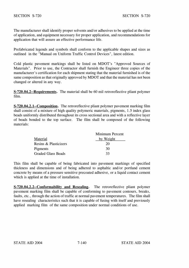
STATE AID 2004 STATE AID 2004
STATE AID 2004 STATE AID 20047-140
SECTION S-720 SECTION S-720
The manufacturer shall identify proper solvents and/or adhesives to be applied at the timeof application, and equipment necessary for proper application, and recommendations forapplication that will assure an effective performance life.
Prefabricated legends and symbols shall conform to the applicable shapes and sizes asoutlined in the "Manual on Uniform Traffic Control Devices", latest edition.
Cold plastic pavement markings shall be listed on MDOT’s "Approved Sources ofMaterials". Prior to use, the Contractor shall furnish the Engineer three copies of themanufacturer's certification for each shipment stating that the material furnished is of thesame composition as that originally approved by MDOT and that the material has not beenchanged or altered in any way.
S-720.04.2--Requirements. The material shall be 60 mil retroreflective pliant polymerfilm.
S-720.04.2.1--Composition. The retroreflective pliant polymer pavement marking filmshall consist of a mixture of high quality polymeric materials, pigments, 1.5 index glassbeads uniformly distributed throughout its cross sectional area and with a reflective layerof beads bonded to the top surface. The film shall be composed of the followingmaterials:
Minimum PercentMaterial by Weight Resins & Plasticizers 20Pigments 30Graded Glass Beads 33
This film shall be capable of being fabricated into pavement markings of specifiedthickness and dimensions and of being adhered to asphaltic and/or portland cementconcrete by means of a pressure sensitive precoated adhesive, or a liquid contact cementwhich is applied at the time of installation.
S-720.04.2.2--Conformability and Resealing. The retroreflective pliant polymerpavement marking film shall be capable of conforming to pavement contours, breaks,faults, etc., through the action of traffic at normal pavement temperatures. The film shallhave resealing characteristics such that it is capable of fusing with itself and previouslyapplied marking film of the same composition under normal conditions of use.

STATE AID 2004 STATE AID 2004
STATE AID 2004 STATE AID 20047-141
SECTION S-720 SECTION S-720
The film shall show patchability when tested as follows:
a. Cut two 1" x 3" pieces of the pliant polymer and mark the reflectiveside of one of the pieces with a pencil to delineate a 1" x 1" area at theend of the piece.
b. Wet the surface of the area delineated with a cloth soaked in contactcement or a mixture of MEK and toluene for one minute, keeping thesurface wet. At the end of one minute, scrape the beads and binder offthe sample and wipe the residual binder from the area. Let the sampledry for at least one minute.
c. Remove the liner from the back of the second piece of film and placethe backside on top of the cleaned area on the first piece. The sample(while held together) should now form one piece four inches long by 1inch wide with the 1" x 1" overlap patch in the center.
d. Place the patched sample on a hard surface under 1,000 grams persquare inch (the area of the overlap splice) maintained at 140oF for twohours.
e. Remove the sample from the heat and allow to cool to 70oF (roomtemperature).
f. Pull the sample in opposite directions to place a shear strain on thepatched area. The two pieces shall not separate without tearing.
S-720.04.2.3--Tensile Strength. The film shall have a minimum tensile strength of 40pounds per square inch of cross section when tested according to ASTM Designation: D638. A sample 6"x 1" x 0.06" shall be tested at a temperature between 70oF and 80oFusing a jaw speed of 12 inches per minute.
S-720.04.2.4--Elongation. The film shall have a minimum elongation of 75% at breakwhen tested according to ASTM Designation: D 638 using a jaw speed of 12 inches perminute.
S-720.04.2.5--Plastic Pull Test. A test specimen made the same size as in S-720.04.2.3shall support a dead weight of four pounds for not less than five minutes at a temperaturebetween 70oF and 80oF.
S-720.04.2.6--Pigmentation. The pigments shall be selected and blended to provide amarking film which is white or yellow conforming to standard highway colors throughthe expected life of the film.
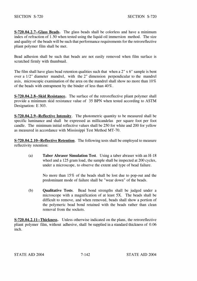
STATE AID 2004 STATE AID 2004
STATE AID 2004 STATE AID 20047-142
SECTION S-720 SECTION S-720
S-720.04.2.7--Glass Beads. The glass beads shall be colorless and have a minimumindex of refraction of 1.50 when tested using the liquid oil immersion method. The sizeand quality of the beads will be such that performance requirements for the retroreflectivepliant polymer film shall be met.
Bead adhesion shall be such that beads are not easily removed when film surface isscratched firmly with thumbnail.
The film shall have glass bead retention qualities such that when a 2" x 6" sample is bentover a 1/2" diameter mandrel, with the 2" dimension perpendicular to the mandrelaxis, microscopic examination of the area on the mandrel shall show no more than 10%of the beads with entrapment by the binder of less than 40%.
S-720.04.2.8--Skid Resistance. The surface of the retroreflective pliant polymer shallprovide a minimum skid resistance value of 35 BPN when tested according to ASTMDesignation: E 303.
S-720.04.2.9--Reflective Intensity. The photometric quantity to be measured shall bespecific luminance and shall be expressed as millicandelas per square foot per footcandle. The minimum initial reflective values shall be 250 for white and 200 for yellowas measured in accordance with Mississippi Test Method MT-70.
S-720.04.2.10--Reflective Retention. The following tests shall be employed to measurereflectivity retention:
(a) Taber Abraser Simulation Test. Using a taber abraser with an H-18wheel and a 125 gram load, the sample shall be inspected at 200 cycles,under a microscope, to observe the extent and type of bead failure.
No more than 15% of the beads shall be lost due to pop-out and thepredominant mode of failure shall be "wear down" of the beads.
(b) Qualitative Tests. Bead bond strengths shall be judged under amicroscope with a magnification of at least 5X. The beads shall bedifficult to remove, and when removed, beads shall show a portion ofthe polymeric bead bond retained with the beads rather than cleanremoval from the sockets.
S-720.04.2.11--Thickness. Unless otherwise indicated on the plans, the retroreflectivepliant polymer film, without adhesive, shall be supplied in a standard thickness of 0.06inch.

STATE AID 2004 STATE AID 2004
STATE AID 2004 STATE AID 20047-143
SECTION S-720 SECTION S-720
S-720.04.2.12--Effective Performance Life. The film, when applied according to therecommendations of the manufacturer, shall provide a neat, durable marking that will notflow or distort due to temperature if the pavement surface remains stable. Althoughreflectivity is reduced by wear, the pliant polymer shall provide a cushioned, resilientsubstrate that reduces bead crushing and loss. The film shall be weather resistant and,through normal traffic wear, shall show no appreciable fading, lifting or shrinkagethroughout the useful life of the marking, and shall show no significant tearing, roll back,or other signs of poor adhesion.
S-720.04.3–Manufacture’s Certification. The Contractor shall furnish the Engineer withthree copies of the manufacture’s certification stating that each lot in a shipment complieswith the requirements of the contract. The Engineer reserves the right to select samplesat random for testing.
S-720.05--Preformed Pavement Markings for Construction Zones.
S-720.05.1--General. In addition to the specific material requirements set forth herein,pavement marking materials must have been approved for listing in MDOT’s "ApprovedSources of Materials" prior to their use. The preformed markings shall consist of whiteor yellow retroreflective films on a conformable backing.
The size, quality, and refractive index of the glass beads shall be such that theperformance requirements for the markings will be met. The bead adhesion shall be suchthat beads are not easily removed when the material surface is scratched with a thumbnail.
The pigments shall be selected and blended to provide pavement markings which are whiteor yellow and conform to standard highway colors.
The markings shall be precoated with a pressure sensitive adhesive and shall be capableof being adhered to asphalt concrete or portland cement concrete in accordance withmanufacturer's instructions without the use of heat, solvents or other additional adhesivemeans, and shall be immediately ready for traffic after application.
The markings shall be provided in specified widths and shapes. Preformed words andsymbols shall conform to the applicable shapes and sizes as outlined in thecurrent edition of the MUTCD.
The materials shall be packaged in accordance with accepted commercial standards, andwhen stored in a cool dry area indoors shall be suitable for use for one year after the dateof purchase.
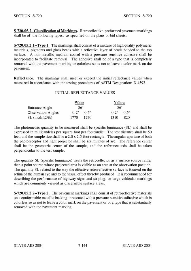
STATE AID 2004 STATE AID 2004
STATE AID 2004 STATE AID 20047-144
SECTION S-720 SECTION S-720
S-720.05.2--Classification of Markings. Retroreflective preformed pavement markingsshall be of the following types, as specified on the plans or bid sheets:
S-720.05.2.1--Type 1. The markings shall consist of a mixture of high quality polymericmaterials, pigments and glass beads with a reflective layer of beads bonded to the topsurface. A non-metallic medium coated with a pressure sensitive adhesive shall beincorporated to facilitate removal. The adhesive shall be of a type that is completelyremoved with the pavement marking or colorless so as not to leave a color mark on thepavement.
Reflectance. The markings shall meet or exceed the initial reflectance values whenmeasured in accordance with the testing procedures of ASTM Designation: D 4592.
INITIAL REFLECTANCE VALUES
White YellowEntrance Angle 86o 86o
Observation Angles 0.2o 0.5o 0.2o 0.5o
SL (mcd/ft2/fc) 1770 1270 1310 820
The photometric quantity to be measured shall be specific luminance (SL) and shall beexpressed in millicandelas per square foot per footcandle. The test distance shall be 50feet, and the sample size shall be a 2.0 x 2.5-foot rectangle. The angular aperture of boththe photoreceptor and light projector shall be six minutes of arc. The reference centershall be the geometric center of the sample, and the reference axis shall be takenperpendicular to the test sample.
The quantity SL (specific luminance) treats the retroreflector as a surface source ratherthan a point source whose projected area is visible as an area at the observation position.The quantity SL related to the way the effective retroreflective surface is focused on theretina of the human eye and to the visual effect thereby produced. It is recommended fordescribing the performance of highway signs and striping, or large vehicular markingswhich are commonly viewed as discernable surface areas.
S-720.05.2.2--Type 2. The pavement markings shall consist of retroreflective materialson a conformable metallic backing, precoated with a pressure sensitive adhesive which iscolorless so as not to leave a color mark on the pavement or of a type that is substantiallyremoved with the pavement marking.

STATE AID 2004 STATE AID 2004
STATE AID 2004 STATE AID 20047-145
SECTION S-720 SECTION S-720
Reflectance. The markings shall meet or exceed the initial reflectance values whenmeasured in accordance with the testing procedures of ASTM Designation: D 4592.
INITIAL REFLECTANCE VALUES
White YellowEntrance Angle 86o 86o
Observation Angles 0.2o 0.5o 0.2o 0.5o
SL (mcd/ft2/fc) 1360 760 820 510
The sample size, test procedure and measurement of test values shall be as prescribed forType 1 in S-720.05.2.1.
S-720.05.3--Certificates of Compliance. The Contractor shall furnish three copies ofcertifications from the manufacturer for each lot of pavement markings used stating thatthe material meets the requirements of the contract.
S-720.06--Raised Pavement Markers.
S-720.06.1--General. Raised pavement markers, including high performance raisedpavement markers, shall be listed in MDOT’s "Approved Sources of Materials".
S-720.06.2--Type of Markers. Pavement and jiggle markers shall conform to one ormore of the following types:
Type A - Non-Reflective White Jiggle Markers. Class 1- Acrylonitrile-Butadiene-Styrene Markers.Class 2 - Ceramic Markers.
Type AY - Non-Reflective Yellow Jiggle Markers.Class 1 - Acrylonitrile-Butadiene-Styrene Polymer Markers.Class 2- Ceramic Markers.
Type B - 2-Way Clear Reflective Markers.Type C - Red-Clear Reflective Markers.Type D - 2-Way Yellow Reflective Markers.Type E - One-Way Clear Reflective Markers.Type F - One-Way Yellow Reflective Markers.Type G - Yellow-Clear Reflective Markers.Type H - Chip Seal Clear Reflective Markers.Type I - Chip Seal Yellow Reflective Markers.
High performance raised pavement markers shall be available in Types B through G.
STATE AID 2004 STATE AID 2004
STATE AID 2004 STATE AID 20047-146
SECTION S-720 SECTION S-720
S-720.06.3--Acceptance Procedures.
S-720.06.3.1--Marker Type A. The Contractor shall furnish the Engineer three copiesof the manufacturer's certified test reports covering all pavement markers shipped to theproject. The certified test report shall show the test results on each part of each sectioncontained in Mississippi Test Method MT-17 and shall state that the markers representedby the test results comply with the specifications contained herein in all respects.
The pavement markers will be accepted on the basis of the manufacturer's certified testreports. The Engineer reserves the right to obtain check samples as deemed necessary fordetermining compliance with this specification
S-720.06.3.1.1--Marker Type B through G. The Contractor shall furnish the Engineerthree copies of the manufacturer's certified test reports covering all pavement markersshipped to the project. The certified test reports shall show the test results on each partof the applicable requirements of ASTM Designation: D 4280.
The pavement markers will be tentatively accepted on the basis of the manufacturer'scertified test reports. The Engineer reserves the right to obtain check samples as deemednecessary for determining compliance with this specification.
S-720.06.3.2--Marker Type H and I. Prior to use, the Contractor shall furnish theEngineer three copies of a certification for each shipment stating that the materialfurnished is of the same composition as that originally approved by MDOT and that thematerial has not been changed or altered in any way. The Engineer reserves the right toobtain check samples as deemed necessary for determining compliance with thisspecification.
S-720.06.4--Sampling, Tolerances, and Packaging. Pavement markers shall conformto sampling, tolerance, and packaging requirements as set out below.
S-720.06.4.1--Sampling. For Marker Type A, H and I, ten (10) markers of each typeand class, selected at random, will constitute a representative sample for each lotregardless of lot size.
For Marker Type B through G, check sampling, when performed, shall require ten (10)markers of each type, selected at random, to constitute a representative sample for eachlot regardless of lot size.
A resample of any marker type will consist of twice as many markers as originallysampled.
STATE AID 2004 STATE AID 2004
STATE AID 2004 STATE AID 20047-147
SECTION S-720 SECTION S-720
S-720.06.4.2--Tolerances.
S-720.06.4.2.1--Tolerances For Marker Type A, H & I. At least 90% of the originalsampling of each lot of markers shall pass all tests with the following exceptions:
When less than 90% but more than 70% pass all tests, a resample of that lot willbe allowed at the request of the Contractor. When less than 70% of the markersfrom the original sample comply with the requirements, the lot represented bythe samples will be rejected and no resample will be allowed. Tolerances forresamples shall be in the same ratio as specified above.
At least two of three specimens, randomly selected for strength, waterabsorption, and autoclave, and also the averages of the three, must pass thestated requirements; otherwise, three additional markers selected at random shallbe tested, and if the same conditions for passing are not met for these latter threemarkers, the lot will be rejected.
S-720.06.4.2.2--Tolerances For Marker Type B through G. At least 90% of the checksampling of each lot of markers shall pass the strength test required in the PhysicalProperties Section of ASTM Designation: D 4280 with the following exceptions:
When less than 90% but more than 70% pass the test, a resample of that lot willbe allowed at the request of the Contractor. When less than 70% of the markersfrom the check sample comply with the requirements, the lot represented by thesamples will be rejected and no resample will be allowed. Tolerances forresamples shall be in the same ratio as specified above.
S-720.06.4.3--Packaging. Shipments shall be made in containers which are acceptableto common carriers and packaged in such a manner as to insure delivery in perfectcondition. All damaged shipments shall be replaced by the Contractor.
Each package shall be clearly marked as to the name of the manufacturer, type, quantityenclosed, lot number, and date of manufacture.
S-720.06.5--Non-Reflective Pavement Markers. Non-reflective jiggle markers shall beeither Class 1 or Class 2. Markers shall be approved products as listed on MDOT's "Listof Approved Sources of Materials".
STATE AID 2004 STATE AID 2004
STATE AID 2004 STATE AID 20047-148
SECTION S-720 SECTION S-720
S-720.06.5.1--Class 1 Markers. Class 1 non-reflective jiggle markers shall consist ofan acrylonitrile-butadiene-styrene polymer or other approved material, and shall be 4inches wide x 6 inches long. Infrared curves of materials used in markers shall matchapproved curves on file at MDOT’s Central Laboratory.
Class 1 markers shall conform to the following requirements when tested in accordancewith Mississippi Test Method: MT-17.
Property Requirement
Heat Resistance No change in shape or appearanceImpact Resistance No break, chip or crackLoad Resistance No break, chip, crack or permanent deformation
S-720.06.5.2--Class 2 Markers. Class 2 non-reflective jiggle markers shall consist ofa heat-fired, vitreous, ceramic base, and a heat-fired, opaque, glazed surface to producethe properties required in these specifications. The bottom of the marker shall not beglazed. The markers shall be produced from any suitable combination of intimately mixedclays, shales, talcs, flints, feldspars, or other inorganic material which will meet theproperties herein required. The markers shall be thoroughly and evenly matured and freefrom defects which affect appearance or serviceability.
Non-reflective markers shall conform to the following finish and testing requirements:
The top surface of the marker shall be in reasonably close conformity with theconfiguration shown on the plans. All edges shall be rounded and any change in curvatureshall be gradual. The top and sides shall be smooth and free of mold marks, pits,indentations, air bubbles, or other objectionable marks or discolorations. The base of allmarkers shall be flat (the deviation from a flat surface shall not exceed 0.05 inch) and freefrom gloss glaze or substances that may reduce its bond to the adhesive.
STATE AID 2004 STATE AID 2004
STATE AID 2004 STATE AID 20047-149
SECTION S-720 SECTION S-720
All tests shall be performed in accordance with Mississippi Test Method: MT-17, whichwill be on file in the MDOT Materials Division.
Test Requirement
Glaze thickness 0.005 inch min.
Moh Hardness 6 min.
Directional reflectance (Type A,white markers only)Glazed Surface 75 min.Body of Marker 70 min.
Yellowness Index (Type A, white markers only)Glazed Surface 0.07 max.Body of Marker 0.12 max.
Color (Type AY, yellow markers only),FHWA Highway Yellow Color Tolerance Chart PR Color # 1
Autoclave Glaze shall not spall,Craze, or peel
Compressive Loading 750 pounds min.
Water Absorption 2.0% max.
S-720.06.6--Reflective Pavement Markers. Reflective pavement markers shall be listedon MDOT’s "Approved Sources of Materials" and shall meet the applicable requirementsof ASTM Designation: D 4280.
S-720.06.7--Adhesive for Pavement Markers.
S-720.06.7.1--General Requirements. The adhesive shall be an asphaltic orthermoplastic material suitable for bonding pavement markers to portland cement concretepavement, hot bituminous pavement and chip-sealed surfaces when the road surface andmarker temperatures are in the range of 50oF to 160oF. The composition of the adhesivemust be such that its properties will not deteriorate when heated to and applied attemperatures up to 425oF using either air or oil-jacketed melters.

STATE AID 2004 STATE AID 2004
STATE AID 2004 STATE AID 20047-150
SECTION S-720 SECTION S-720
S-720.06.7.2--Specific Requirements. In addition to the specific requirements set forthherein, the adhesive shall be listed on MDOT’s "Approved Sources of Materials" priorto its use.
S-720.06.7.3--Packaging and Labeling. The adhesive shall be packaged in self-releasingcardboard containers which will stack properly. The label shall show the manufacturer,quantity, and lot or batch number. "Adhesive for Pavement Markers" or "Adhesive forTraffic Markers" shall be printed in bold lettering on the label.
S-720.06.7.4--Sampling. When required by the Engineer, a minimum of 10 pounds ofadhesive per lot or batch received shall be submitted for compliance testing. This maybe submitted in the form of an adhesive testing package from each batch or materialobtained from a package shipped to the project.
S-720.06.7.5--Manufacturer's Certified Test Report. The adhesive will be acceptedby a manufacturer's certified test report. The certified test report shall show the testresults and shall state that the adhesive represented by the test results meets all therequirements of the contract and has the properties and characteristics as herein specified.It shall be the Contractor's responsibility to furnish three copies of the manufacturer's testreport for each batch of adhesive shipped to the project. The Engineer reserves the rightto take samples for testing as he deems necessary.
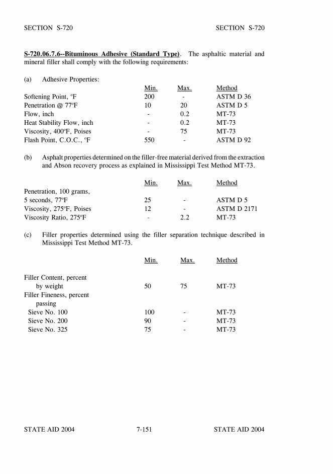
STATE AID 2004 STATE AID 2004
STATE AID 2004 STATE AID 20047-151
SECTION S-720 SECTION S-720
S-720.06.7.6--Bituminous Adhesive (Standard Type). The asphaltic material andmineral filler shall comply with the following requirements:
(a) Adhesive Properties:Min. Max. Method
Softening Point, oF 200 - ASTM D 36Penetration @ 77oF 10 20 ASTM D 5Flow, inch - 0.2 MT-73Heat Stability Flow, inch - 0.2 MT-73Viscosity, 400oF, Poises - 75 MT-73Flash Point, C.O.C., oF 550 - ASTM D 92
(b) Asphalt properties determined on the filler-free material derived from the extractionand Abson recovery process as explained in Mississippi Test Method MT-73.
Min. Max. MethodPenetration, 100 grams,5 seconds, 77oF 25 - ASTM D 5Viscosity, 275oF, Poises 12 - ASTM D 2171Viscosity Ratio, 275oF - 2.2 MT-73
(c) Filler properties determined using the filler separation technique described inMississippi Test Method MT-73.
Min. Max. Method
Filler Content, percentby weight 50 75 MT-73
Filler Fineness, percentpassing
Sieve No. 100 100 - MT-73 Sieve No. 200 90 - MT-73 Sieve No. 325 75 - MT-73
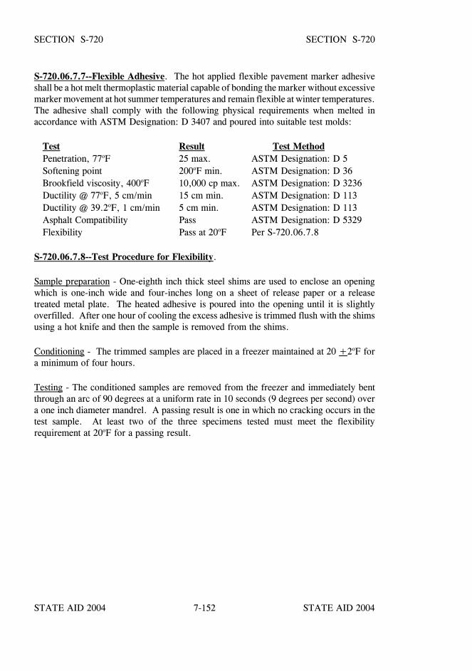
STATE AID 2004 STATE AID 2004
STATE AID 2004 STATE AID 20047-152
SECTION S-720 SECTION S-720
S-720.06.7.7--Flexible Adhesive. The hot applied flexible pavement marker adhesiveshall be a hot melt thermoplastic material capable of bonding the marker without excessivemarker movement at hot summer temperatures and remain flexible at winter temperatures.The adhesive shall comply with the following physical requirements when melted inaccordance with ASTM Designation: D 3407 and poured into suitable test molds:
Test Result Test MethodPenetration, 77oF 25 max. ASTM Designation: D 5Softening point 200oF min. ASTM Designation: D 36Brookfield viscosity, 400oF 10,000 cp max. ASTM Designation: D 3236Ductility @ 77oF, 5 cm/min 15 cm min. ASTM Designation: D 113Ductility @ 39.2oF, 1 cm/min 5 cm min. ASTM Designation: D 113Asphalt Compatibility Pass ASTM Designation: D 5329Flexibility Pass at 20oF Per S-720.06.7.8
S-720.06.7.8--Test Procedure for Flexibility.
Sample preparation - One-eighth inch thick steel shims are used to enclose an openingwhich is one-inch wide and four-inches long on a sheet of release paper or a releasetreated metal plate. The heated adhesive is poured into the opening until it is slightlyoverfilled. After one hour of cooling the excess adhesive is trimmed flush with the shimsusing a hot knife and then the sample is removed from the shims.
Conditioning - The trimmed samples are placed in a freezer maintained at 20 +2oF fora minimum of four hours.
Testing - The conditioned samples are removed from the freezer and immediately bentthrough an arc of 90 degrees at a uniform rate in 10 seconds (9 degrees per second) overa one inch diameter mandrel. A passing result is one in which no cracking occurs in thetest sample. At least two of the three specimens tested must meet the flexibilityrequirement at 20oF for a passing result.
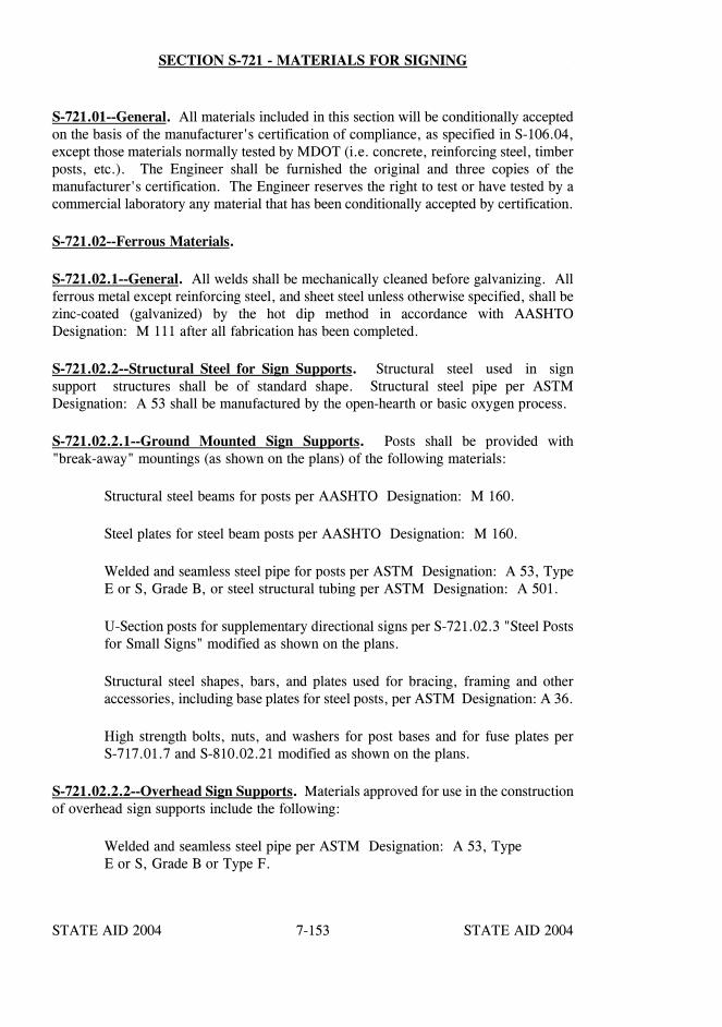
STATE AID 2004 STATE AID 2004
STATE AID 2004 STATE AID 20047-153
SECTION S-721 - MATERIALS FOR SIGNING
S-721.01--General. All materials included in this section will be conditionally acceptedon the basis of the manufacturer's certification of compliance, as specified in S-106.04,except those materials normally tested by MDOT (i.e. concrete, reinforcing steel, timberposts, etc.). The Engineer shall be furnished the original and three copies of themanufacturer's certification. The Engineer reserves the right to test or have tested by acommercial laboratory any material that has been conditionally accepted by certification.
S-721.02--Ferrous Materials.
S-721.02.1--General. All welds shall be mechanically cleaned before galvanizing. Allferrous metal except reinforcing steel, and sheet steel unless otherwise specified, shall bezinc-coated (galvanized) by the hot dip method in accordance with AASHTODesignation: M 111 after all fabrication has been completed.
S-721.02.2--Structural Steel for Sign Supports. Structural steel used in signsupport structures shall be of standard shape. Structural steel pipe per ASTMDesignation: A 53 shall be manufactured by the open-hearth or basic oxygen process.
S-721.02.2.1--Ground Mounted Sign Supports. Posts shall be provided with"break-away" mountings (as shown on the plans) of the following materials:
Structural steel beams for posts per AASHTO Designation: M 160.
Steel plates for steel beam posts per AASHTO Designation: M 160.
Welded and seamless steel pipe for posts per ASTM Designation: A 53, TypeE or S, Grade B, or steel structural tubing per ASTM Designation: A 501.
U-Section posts for supplementary directional signs per S-721.02.3 "Steel Postsfor Small Signs" modified as shown on the plans.
Structural steel shapes, bars, and plates used for bracing, framing and otheraccessories, including base plates for steel posts, per ASTM Designation: A 36.
High strength bolts, nuts, and washers for post bases and for fuse plates perS-717.01.7 and S-810.02.21 modified as shown on the plans.
S-721.02.2.2--Overhead Sign Supports. Materials approved for use in the constructionof overhead sign supports include the following:
Welded and seamless steel pipe per ASTM Designation: A 53, TypeE or S, Grade B or Type F.
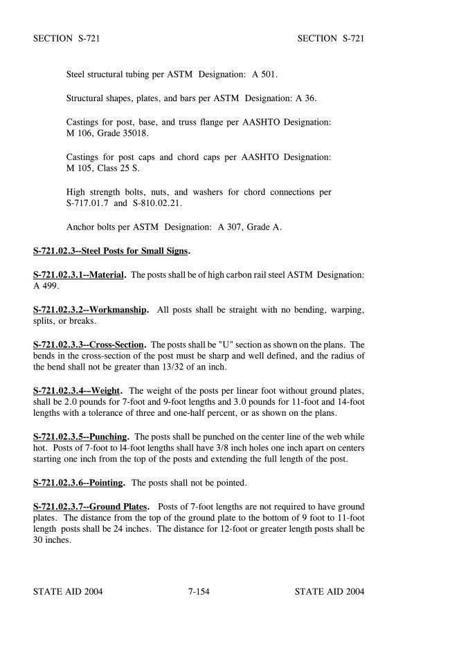
STATE AID 2004 STATE AID 2004
STATE AID 2004 STATE AID 20047-154
SECTION S-721 SECTION S-721
Steel structural tubing per ASTM Designation: A 501.
Structural shapes, plates, and bars per ASTM Designation: A 36.
Castings for post, base, and truss flange per AASHTO Designation:M 106, Grade 35018.
Castings for post caps and chord caps per AASHTO Designation:M 105, Class 25 S.
High strength bolts, nuts, and washers for chord connections perS-717.01.7 and S-810.02.21.
Anchor bolts per ASTM Designation: A 307, Grade A.
S-721.02.3--Steel Posts for Small Signs.
S-721.02.3.1--Material. The posts shall be of high carbon rail steel ASTM Designation:A 499.
S-721.02.3.2--Workmanship. All posts shall be straight with no bending, warping,splits, or breaks.
S-721.02.3.3--Cross-Section. The posts shall be "U" section as shown on the plans. Thebends in the cross-section of the post must be sharp and well defined, and the radius ofthe bend shall not be greater than 13/32 of an inch.
S-721.02.3.4-–Weight. The weight of the posts per linear foot without ground plates,shall be 2.0 pounds for 7-foot and 9-foot lengths and 3.0 pounds for 11-foot and 14-footlengths with a tolerance of three and one-half percent, or as shown on the plans.
S-721.02.3.5--Punching. The posts shall be punched on the center line of the web whilehot. Posts of 7-foot to l4-foot lengths shall have 3/8 inch holes one inch apart on centersstarting one inch from the top of the posts and extending the full length of the post.
S-721.02.3.6--Pointing. The posts shall not be pointed.
S-721.02.3.7--Ground Plates. Posts of 7-foot lengths are not required to have groundplates. The distance from the top of the ground plate to the bottom of 9 foot to 11-footlength posts shall be 24 inches. The distance for 12-foot or greater length posts shall be30 inches.
STATE AID 2004 STATE AID 2004
STATE AID 2004 STATE AID 20047-155
SECTION S-721 SECTION S-721
S-721.02.4--Reinforcing Steel. Reinforcing steel used shall conform to S-711 and shallbe placed in accordance with S-602.
S-721.02.5--Bolts, Nuts, Washers, Screws, and other Hardware. Except as otherwisespecified, all bolts, nuts, washers, sheet metal screws, and machine screws shall be coatedby the zinc chromate process. The zinc chromate process shall be in accordance with therequirements of ASTM Designation: B633. Bolts shall have a 1/2-inch head and shallmeet the requirements of ASTM Designation: A307, Grade A. Nuts shall be self-lockingand shall meet the requirements of ASTM Designation: A563. Flat washers shall beinstalled between the sign support and the self-locking nut and shall meet the requirementsof ANSI Designation: B27.2. Sheet metal screws shall meet the requirements of ANSIDesignation: B18.6.4. Machine screws shall meet the requirements of ANSI Designation:B18.6.3. Vinyl spacers shall be installed between the bolt head and the sign face and shallmeet the following maximum dimensions: 7/8-inch outside diameter by 3/8-inch insidediameter by 1/16-inch thickness.
Post clips used with extruded panel signs shall be cast aluminum per ASTM Designation:B 108, Alloy No. 356.0-T6 or extruded aluminum per ASTM Designation: B 221, Alloy6063-T6. Unless otherwise specified, all bolts, sheet metal screws, and machine screwsused in assembling signs, frames, and post braces, including post clips and panel bolts,shall be in accordance with ASTM Designation: A 307, Grade A.
S-721.02.5.1--Vandal-Resistant Bolts, Vandal-Resistant Nuts, Nylon Washers andother Hardware. When Vandal-Resistant Hardware for signs are noted on the plans,all bolts, nuts, washers, sheet metal screws, and machine screws shall be coated by thezinc chromate process. The zinc chromate process shall be in accordance with therequirements of ASTM Designation: B633. Bolts shall be 5/16 inch diameter, 2 1/2inch long (minimum) carriage bolts, hex bolts or " one-way" bolts. Carriage bolts shallbe round headed with a square neck and shall not have any slots or other opening for anytype of tool. This square neck shall fit snugly and not move when tightened into thehole in the sign face. Hex bolt and one-way bolt heads shall not be square necked, butshall tighten flat against the sign face. One-way bolts shall be able to be tightened but notloosened by a screw driver. If hex bolts or one-way bolts are used, a nylon washer shallbe provided to place between the bolt head and the sign face.
An approved vandal-resistant nut will be required regardless of the type of bolt used. A5/16 inch inside diameter rustproofed steel, aluminum or approved equal washer shall beprovided to place between the post and the vandal-resistant nut. The outside diameter ofthis washer will be dependent on the type of vandal-resistant nut used.
S-721.03--Aluminum. All aluminum shall be free from corrosion, white rust, waterstains, dirt, and grease. Fabrication shall be accomplished in a uniform and workmanlikemanner. All fabrication, including cutting and punching of holes, shall be completed priorto metal treatment. Sign blanks shall be cut to size and shape and shall be free of buckles,
STATE AID 2004 STATE AID 2004
STATE AID 2004 STATE AID 20047-156
SECTION S-721 SECTION S-721
warps, dents, cockles, burrs, and defects resulting from fabrication. The surface of allsign blanks shall be flat.
All blanks not having corner radii shall have square (90o) corners to facilitate signfabrication.
All blanks requiring holes shall have “STATE AID PROJECT” debossed on the blank ina location so as not to be covered by the post when erected. The debossed letters shallbe not less than 3/8 inch high and shall be approximately 0.006 inch deep so as not to bevisible on the other side of the blank.
S-721.03.1--Sheet Aluminum. Sheet aluminum or blanks shall meet the requirementsof ASTM Designation: B 209, Alloy 6061-T6 or 5052-H38. Gauge, dimension,punching and corner radii shall be in accordance with the plans.
S-721.03.2--Extruded Signs. Extruded sign panels, extruded moldings, andextruded post clips shall meet the requirements of ASTM Designation: B 221, Alloy6063-T6. Sections and dimensions shall be as shown on the plans. The panel shall be ofthe butt type, designed to withstand a wind pressure of 50 pounds per square foot. Allpanels shall be flat and straight within commercial tolerances as established by thealuminum industry. Extruded sign sections shall be subject to approval by the Engineer.Extruded sign sections shall be provided with slotted bolt holes. Sign moldings and postclips shall be designed for the sign panel section with which it is used. Sign moldingsshall be anchored to the sign panels by means of aluminum pull-through rivets or selftapping screws.
S-721.03.3--Overhead Sign Support Material. Material approved for use in theconstruction of Overhead Sign Supports include the following:
Extruded structural tube and pipe per ASTM Designation: B 221, B 241 orB 429, Alloy 6061-T6.
Extruded structural tube and pipe per ASTM Designation: B 221, B 241 orB 429, Alloy 6063-T6.
Structural shapes per ASTM Designation: B 308, Alloy 6061-T6.
Sheet and plate per ASTM Designation: B 209, Alloy 6061-T6.
Castings for post and chord caps per ASTM Designation: B 26, Alloy No.356.0.
STATE AID 2004 STATE AID 2004
STATE AID 2004 STATE AID 20047-157
SECTION S-721 SECTION S-721
Base and filler metals for welding shall be as listed below:
BASE FILLERMETAL ALLOYS METAL ALLOYS
6061-T6 to 6061-T6 ER-55566063-T6 to 6061-T6 ER-4043, ER-5356 or 6063-T6 or ER-5556
S-721.04--Concrete. Unless otherwise specified, concrete shall be Class B.Composition, manufacture, and placement shall be in accordance with S-601.
S-721.05--Colors and Paint. All colors for signs shall match FHWA Specificationsfor standard highway sign colors. The molding which is attached to the extruded panelsigns shall be painted with a semi-gloss baking enamel meeting Federal SpecificationTT-E-529a.
Aluminum paint shall conform to S-710.02.1. Transparent and black opaque processcolors used in silk screening shall be that or equal to that recommended by themanufacturer of the retroreflective sheeting, and shall match FHWA Specifications forstandard highway sign colors. Toning of certain colors for adjustment in hue shall beaccomplished in accordance with the recommendations of the manufacturer of the processpaste.
S-721.06--Reflective Sheeting.
S-721.06.1--General. Retroreflective sheeting materials shall comply with all applicablerequirements of ASTM Designation: D 4956, except as specifically modified herein, andbe listed on MDOT’s "Approved Sources of Materials".
Reflective sheeting shall be one of the following types.
Type III. A high-intensity retroreflective sheeting. This shall be an encapsulatedglass-bead or unmetallized microprismatic retroreflective material. Thissheeting shall have a protected, pre-coated, pressure-sensitive adhesivebacking.
Type VII. A super high-intensity retroreflective sheeting. This shall be anunmetallized microprismatic retroreflective material. This sheeting shallhave a protected, pre-coated, pressure sensitive adhesive backing.
STATE AID 2004 STATE AID 2004
STATE AID 2004 STATE AID 20047-158
SECTION S-721 SECTION S-721
Type VIII. A super high-intensity retroreflective sheeting. This shall be anunmetallized microprismatic retroreflective material. This sheeting shallhave a protected, pre-coated, pressure sensitive adhesive backing.
Type IX. A very-high intensity retroreflective sheeting. This shall be anunmetallized, microprismatic retroreflective material. This sheetingshall have a protected, pre-coated, pressure sensitive, adhesive backing.
All other retroreflective sheeting shall be as shown in the plans.
S-721.06.2--Performance Requirements. The retroreflective sheeting shall have thefollowing minimum brightness values at 0.2o and 0.5o observation angle, in addition 1.0o
for Type IX sheeting, expressed as average candelas per footcandle per square foot ofmaterial.
Sheetings and inks processed and applied in accordance with the manufacturer’srecommendations, shall perform effectively for the number of years stated below. Thesheeting will be considered unsatisfactory if it has deteriorated due to natural causes to theextent that: (1) the sign is ineffective for its intended purpose when viewed from amoving vehicle under normal day and night driving conditions or (2) the coefficient ofretroreflection is less than the minimum specified for that sheeting during the periodslisted below. For screen printed transparent colored areas on white sheeting, thecoefficients of retroreflection shall not be less than 70% of the values for thecorresponding color in the table.
Type III Sheeting Retain 85% of initial values listed in Table 1 through 7 yearsRetain 80% of initial values listed in Table 1 between 7 & 10 years
Type VII Sheeting Retain 85% of initial values listed in Table 2 through 7 yearsRetain 80% of initial values listed in Table 2 between 7 & 10yearsRetain 50% of initial values listed in Table 2 through 3 years forFluorescent Orange
Type VIII Sheeting Retain 85% of initial values listed in Table3 through 7 yearsRetain 80% of initial values listed in Table 3 between 7 & 10yearsRetain 50% of initial values listed in Table 3 through 3 years forFluorescent OrangeRetain 80% of initial values listed in Table 3 through 7 years forFluorescent Yellow/Green & Fluorescent Yellow
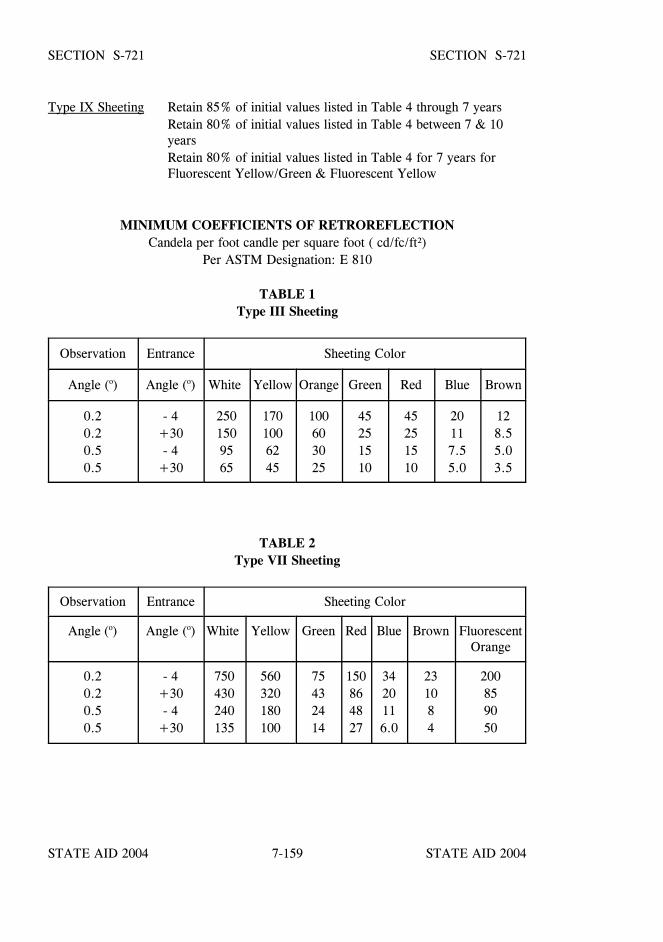
STATE AID 2004 STATE AID 2004
STATE AID 2004 STATE AID 20047-159
SECTION S-721 SECTION S-721
Type IX Sheeting Retain 85% of initial values listed in Table 4 through 7 yearsRetain 80% of initial values listed in Table 4 between 7 & 10yearsRetain 80% of initial values listed in Table 4 for 7 years forFluorescent Yellow/Green & Fluorescent Yellow
MINIMUM COEFFICIENTS OF RETROREFLECTIONCandela per foot candle per square foot ( cd/fc/ft²)
Per ASTM Designation: E 810
TABLE 1Type III Sheeting
Observation Entrance Sheeting Color
Angle (o) Angle (o) White Yellow Orange Green Red Blue Brown
0.20.20.50.5
- 4+30- 4
+30
2501509565
1701006245
100603025
45251510
45251510
20117.55.0
128.55.03.5
TABLE 2Type VII Sheeting
Observation Entrance Sheeting Color
Angle (o) Angle (o) White Yellow Green Red Blue Brown FluorescentOrange
0.20.20.50.5
- 4+30- 4
+30
750430240135
560320180100
75432414
150864827
3420116.0
231084
200859050

STATE AID 2004 STATE AID 2004
STATE AID 2004 STATE AID 20047-160
SECTION S-721 SECTION S-721
MIN
IMU
M C
OE
FF
ICIE
NT
S OF
RE
TR
OR
EF
LE
CT
ION
Candela per foot candle per square foot (cd/fc/ft 2)
TA
BL
E 3
Type V
III Sheeting
ObservationA
ngle ( o)E
ntranceA
ngle ( o)W
hiteY
ellowG
reenR
edB
lueB
rown
FluorescentO
rangeF
luorescentY
ellow/G
reenF
luorescentY
ellow
0.2- 4
700525
70105
4221
200480
375
0.2+
3325
24533
4920
1085
240170
0.5- 4
250190
2538
157.5
90235
165
0.5+
3115
8612
177
3.550
11085
TA
BL
E 4
Type IX
Sheeting
ObservationA
ngle ( o)E
ntranceA
ngle ( o)W
hiteY
ellowG
reenR
edB
lueF
luorescentY
ellow/G
reenF
luorescentY
ellow
0.2- 4.0
380285
3876
17325
240
0.2+
30.0215
16222
4310
205150
0.5- 4.0
240180
2448
11240
165
0.5+
30.0135
10014
276.0
11075
1.0- 4.0
8060
816
3.665
45
1.0+
30.045
344.5
92.0
3525
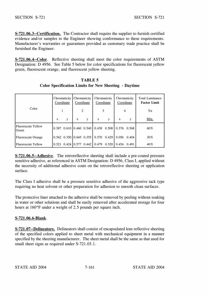
STATE AID 2004 STATE AID 2004
STATE AID 2004 STATE AID 20047-161
SECTION S-721 SECTION S-721
S-721.06.3--Certification. The Contractor shall require the supplier to furnish certifiedevidence and/or samples to the Engineer showing conformance to these requirements.Manufacturer's warranties or guarantees provided as customary trade practice shall befurnished the Engineer.
S-721.06.4--Color. Reflective sheeting shall meet the color requirements of ASTMDesignation: D 4956. See Table 5 below for color specifications for fluorescent yellowgreen, fluorescent orange, and fluorescent yellow sheeting.
TABLE 5Color Specification Limits for New Sheeting - Daytime
Color
ChromaticityCoordinate
ChromaticityCoordinate
ChromaticityCoordinate
ChromaticityCoordinate
Total LuminanceFactor Limit
1 2 3 4 Yn
x y x y x y x y Min.
Fluorescent YellowGreen
0.387 0.610 0.460 0.540 0.438 0.508 0.376 0.568 60%
Fluorescent Orange 0.562 0.350 0.645 0.355 0.570 0.429 0.056 0.404 30%
Fluorescent Yellow 0.521 0.424 0.577 0.442 0.479 0.520 0.454 0.491 40%
S-721.06.5--Adhesive. The retroreflective sheeting shall include a pre-coated pressuresensitive adhesive, as referenced in ASTM Designation: D 4956, Class I, applied withoutthe necessity of additional adhesive coats on the retroreflective sheeting or applicationsurface.
The Class I adhesive shall be a pressure sensitive adhesive of the aggressive tack typerequiring no heat solvent or other preparation for adhesion to smooth clean surfaces.
The protective liner attached to the adhesive shall be removed by peeling without soakingin water or other solutions and shall be easily removed after accelerated storage for fourhours at 160ºF under a weight of 2.5 pounds per square inch.
S-721.06.6-Blank.
S-721.07--Delineators. Delineators shall consist of encapsulated lens reflective sheetingof the specified colors applied to sheet metal with mechanical equipment in a mannerspecified by the sheeting manufacturer. The sheet metal shall be the same as that used forsmall sheet signs as required under S-721.03.1.
STATE AID 2004 STATE AID 2004
STATE AID 2004 STATE AID 20047-162
SECTION S-721 SECTION S-721
S-721.07.1--Flexible Posts. Flexible posts for delineators shall be composed of highimpact fiberglass reinforced composite, engineering blended plastic or thermosettingpolymers which is reasonably unaffected by long term U.V. exposure. Flexible posts fordelineators must be one from MDOT’s "Approved Sources of Materials". Prior to use,the Contractor shall furnish the Engineer three copies of the manufacturer's certificationfor each shipment stating that the material furnished is of the same composition as thatoriginally approved by the MDOT and that the material has not been changed or alteredin any way.
S-721.07.1.1--Performance Testing for Flexible Posts.
S-721.07.1.1.1--Impact Resistance. The post must be self erecting after withstanding10 vehicle impacts at temperatures of 0oF or above without complete loss of serviceability.The impacts shall be made at an impact angle of 25 ±5o with a sedan at 35 mph.
S-721.07.1.1.2--Heat Resistance. A post shall be conditioned a minimum of two hoursin an oven at 115o ±3oF. The conditioned post shall be capable of straightening itselfwithin 10 seconds when bent 90o at or near midpoint for each of four bends. The test oneach post shall be completed within two minutes after removal from the oven. The postshall be bent in the direction to form a 90o angle on the convex side of the post.
S-721.07.1.1.3--Cold Resistance. A post shall be conditioned a minimum of two hoursat -5o ±3oF in an environmentally controlled test chamber. Testing shall be performedin the environmental chamber. The conditioned post shall not be adversely effected whenbent at or near midpoint to a 90o angle formed on the convex side of the post. The postshall return to its original shape within 60 seconds for each of four separate bends.
S-721.07.1.1.4--Color Fastness. The post materials shall be exposed for 1000 hours inan Atlas Type B or BH Xenon Arc Weatherometer per ASTM Designation: G 26 with nosignificant yellowing or darkening.
S-721.07.1.2--Acceptance Procedure. Flexible posts for delineators must be one fromMDOT’s "Approved Sources of Materials". Prior to use, the Contractor shall furnish theEngineer three copies of the manufacturer's certification for each shipment stating that thematerial furnished is of the same composition as that originally approved by MDOT andthat the material has not been changed or altered in any way.
STATE AID 2004 STATE AID 2004
STATE AID 2004 STATE AID 20047-163
SECTION S-721 SECTION S-721
S-721.08--Removable Copy. Removable copy shall include letters, numerals, symbols,and borders. All designs shall conform to the MUTCD. All removable copy will beattached to the sign face from the front by means of a huck or a cherry rivet gun andaluminum pull-through rivets without the use of clips. Removable copy shall consist ofencapsulated lens retroreflective sheeting which has been carefully selected by themanufacturer for uniformity of day and night appearance and applied to flat aluminumbacking. The backing shall be a minimum of .032" thick aluminum sheet as per ASTMDesignation: B 209, alloy 3003-H14. The metal treatment shall be the same as that foraluminum sheet.
S-721.09--Timber Sign Posts. The posts shall conform to the requirements set forth inS-712.01.2, except that the preservative shall conform with S-718.04.3 or S-718.04.4.
S-721.10--Direct Applied Copy. Direct applied copy which is to be provided on guidedirectional signs, ground mounted or overhead , shall be directly applied to the sign face.Direct applied copy shall include letters, numerals, symbols and borders. All designs shallconform to the MUTCD. All direct applied copy shall be attached to the sign face bymeans of pressure sensitive adhesive meeting the requirements of S-721.06.5. Directapplied copy shall consist of encapsulated lens retroreflective sheeting meeting therequirements of S-721.06.
All signs shall be delivered to the site of their erection in one piece with all bolts, rivets,moldings, extrusions, copy, and other required appurtenances thereto attached, completeand ready to be mounted to the sign support structure. Any required supplemental ortemporary supports required for stability during transport shall be firmly attached buteasily removed prior to erection.
STATE AID 2004 STATE AID 2004
STATE AID 2004 STATE AID 20047-164
SECTION S-722 - GEOGRIDS
S-722.01--Geogrids.
S-722.01.1--General. A geogrid is defined as a geosynthetic formed by a regularnetwork of integrally connected elements with apertures greater than 0.25 inch to allowinterlocking with surrounding soil, rock, earth and other surrounding materials to functionprimarily as reinforcement.
The geogrid shall be creep tested in accordance with ASTM Designation: D 5262. Thelong term design load that shall be reported for design use, shall be that load at which nomore than 10% strain occurs over a 100-year design life of the geogrid, as calculated fromtests run on representative samples for no less than 10,000 hours. The long term designload shall be reported unfactored, as the AASHTO strength reduction - Durability andInstallation, and safety factors - will be considered by the MDOT Geotechnical Branchon a site specific design basis.
The geogrid shall meet the physical requirements of Table II for the type shown on theplans and shall be selected from MDOT’s list of “Approved Sources of Materials.”
The geogrid shall be mildew resistant and inert to biological degradation and naturallyencountered chemicals, alkalis and acids. The geogrid shall contain stabilizers and/orinhibitors, or a resistance finish or covering to make it resistant to deterioration fromdirect sunlight, ultraviolet rays, and heat.
S-722.02--Marking, Shipment and Storage. Each roll or container of geogrid shall bevisibly labeled with the name of the manufacturer, trade name of the product, lot number,and quantity of material. In addition, each roll or container shall be clearly tagged toshow the type designation that corresponds to that required by the plans. During shipmentand storage the geogrid shall be protected from direct sunlight, and temperatures above120oF or below 0oF. The geogrid shall either be wrapped and maintained in a heavy dutyprotective covering or stored in a safe enclosed area to protect from damage duringprolonged storage.
S-722.03--Manufacturer’s Certification. The Contractor shall furnish the Engineerthree copies of the manufacturer’s certified test reports indicating that the geogridfurnished conforms to the requirements of the specifications and is of the samecomposition as that originally approved by MDOT.
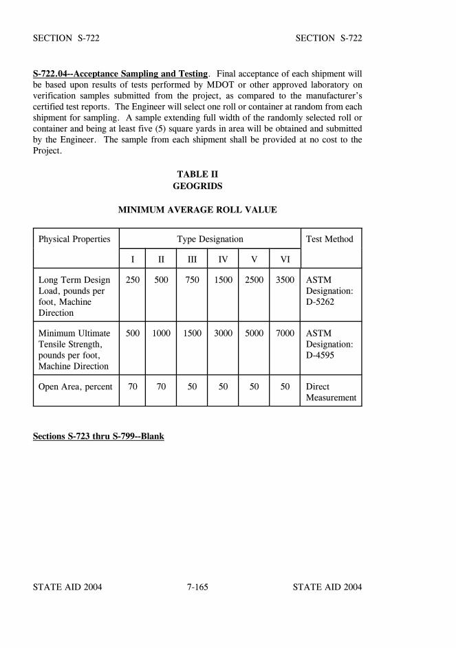
STATE AID 2004 STATE AID 2004
STATE AID 2004 STATE AID 20047-165
SECTION S-722 SECTION S-722
S-722.04--Acceptance Sampling and Testing. Final acceptance of each shipment willbe based upon results of tests performed by MDOT or other approved laboratory onverification samples submitted from the project, as compared to the manufacturer’scertified test reports. The Engineer will select one roll or container at random from eachshipment for sampling. A sample extending full width of the randomly selected roll orcontainer and being at least five (5) square yards in area will be obtained and submittedby the Engineer. The sample from each shipment shall be provided at no cost to theProject.
TABLE IIGEOGRIDS
MINIMUM AVERAGE ROLL VALUE
Physical Properties Type Designation Test Method
I II III IV V VI
Long Term DesignLoad, pounds perfoot, MachineDirection
250 500 750 1500 2500 3500 ASTMDesignation:D-5262
Minimum UltimateTensile Strength,pounds per foot,Machine Direction
500 1000 1500 3000 5000 7000 ASTMDesignation:D-4595
Open Area, percent 70 70 50 50 50 50 DirectMeasurement
Sections S-723 thru S-799--Blank

STATE AID 2004 STATE AID 2004
STATE AID 2004 STATE AID 2004
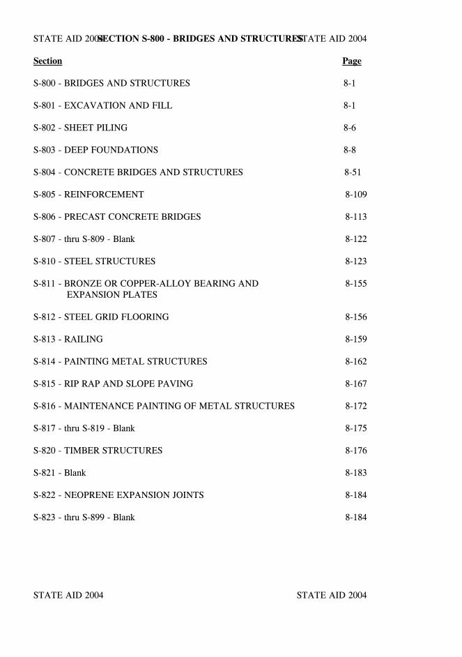
STATE AID 2004 STATE AID 2004
STATE AID 2004 STATE AID 2004
SECTION S-800 - BRIDGES AND STRUCTURES
Section Page
S-800 - BRIDGES AND STRUCTURES 8-1
S-801 - EXCAVATION AND FILL 8-1
S-802 - SHEET PILING 8-6
S-803 - DEEP FOUNDATIONS 8-8
S-804 - CONCRETE BRIDGES AND STRUCTURES 8-51
S-805 - REINFORCEMENT 8-109
S-806 - PRECAST CONCRETE BRIDGES 8-113
S-807 - thru S-809 - Blank 8-122
S-810 - STEEL STRUCTURES 8-123
S-811 - BRONZE OR COPPER-ALLOY BEARING AND 8-155EXPANSION PLATES
S-812 - STEEL GRID FLOORING 8-156
S-813 - RAILING 8-159
S-814 - PAINTING METAL STRUCTURES 8-162
S-815 - RIP RAP AND SLOPE PAVING 8-167
S-816 - MAINTENANCE PAINTING OF METAL STRUCTURES 8-172
S-817 - thru S-819 - Blank 8-175
S-820 - TIMBER STRUCTURES 8-176
S-821 - Blank 8-183
S-822 - NEOPRENE EXPANSION JOINTS 8-184
S-823 - thru S-899 - Blank 8-184

STATE AID 2004 STATE AID 2004
STATE AID 2004 STATE AID 2004
STATE AID 2004 STATE AID 2004
STATE AID 2004 STATE AID 20048-1
SECTION S-800 - BRIDGES AND STRUCTURES
SECTION S-801 - EXCAVATION AND FILL
S-801.01--Description. Foundation excavation shall include the removal of all material,of whatever nature, necessary for the construction of foundations and substructures ofbridges in accordance with the plans or as directed by the Engineer. When not shown asa pay item, it shall include the furnishing of all necessary equipment and the constructionof all cribs, cofferdams, dewatering, etc. necessary for execution of the work. It shallalso include the subsequent removal of cofferdams and cribs and the placement of allnecessary backfill as hereinafter specified. It shall also include the disposal of excavatedmaterial, which is not required for backfill or other specified usage, in a manner and inlocations that will not be unsightly or affect the carrying capacity of the channel or otherrelated drainage.
Unless a greater area is necessary for construction, the bridge site shall be the areadefined in S-101.02. Clearing and grubbing shall be in accordance with the provisionsof S-201.04.
All substructures, where practicable, shall be constructed in open excavation, and wherenecessary, the excavation shall be shored, braced, or protected by cofferdams inaccordance with approved methods. When footings can be placed in the dry without theuse of cribs or cofferdams, back forms may be omitted with the approval of the Engineerand the entire excavation filled with concrete to the top of the footing. The additionalconcrete required shall be placed at the expense of the Contractor.
S-801.02--Preservation of Channel. Unless otherwise specified, no excavation shall bemade outside of cribs, cofferdams, or sheet piling, and the natural stream bed adjacent tothe structure shall not be disturbed without permission of the Engineer. If any excavationor dredging is made at the site of the structure before cribs or cofferdams are in place, theContractor shall, without extra compensation and after the foundation base is in place,backfill all such excavation to the original ground surface or river bed with materialsatisfactory to the Engineer. Material deposited within the stream area from foundationor other excavation or from the filling of cofferdams shall be removed and the stream areafreed from obstruction thereby.
S-801.03--Depth of Footings. The elevations shown on the plans for bottoms of footingsshall be considered as approximate, and the State Aid Engineer may order, in writing,changes in dimensions or elevations necessary for a satisfactory foundation.
S-801.04--Preparation of Foundations for Footings. All rock or other hard foundationmaterial shall be cut to a firm surface, either level, stepped, or roughened as may bedirected by the Engineer, and then cleaned of all loose material. All seams shall becleaned out and filled with concrete, mortar, or grout.
Excavation and preparation of foundations for footings for box bridges shall be inaccordance with the provisions of S-206.
STATE AID 2004 STATE AID 2004
STATE AID 2004 STATE AID 20048-2
SECTION S-801 SECTION S-801
S-801.05--Cofferdams and Cribs.
S-801.05.1--General. Cofferdams and cribs shall be safely designed and constructed toadequate depths and heights, and be made as water-tight as is necessary for the properperformance of the work to be done inside them. In general, the interior dimensions ofcofferdams and cribs shall be sufficient to permit construction of forms and the inspectionof their exteriors and to permit pumping outside of the forms. Cofferdams or cribs whichtilt or move laterally during the process of sinking shall be righted, reset, or enlarged soas to provide the necessary clearance. All corrective work shall be at the expense of theContractor.
When conditions are encountered which, in the opinion of the Engineer, make itimpracticable to dewater the foundation, he may require the construction of a concrete sealof the dimensions necessary, with approval of the State Aid Engineer. The foundationshall then be pumped out and the balance of the masonry placed in the dry. Whenweighted cribs are employed, and the weight is utilized to partially overcome thehydrostatic pressure acting against the bottom of the foundation seal, special anchoragesuch as dowels or keys shall be provided to transfer the entire weight of the crib into thefoundation seal. During the placing of a foundation seal, the water elevation inside thecofferdam shall be controlled to prevent any flow through the seal, and if the cofferdamis to remain in place, it shall be vented or ported at low water level.
S-801.05.2--Protection of Concrete. Cofferdams or cribs shall be constructed so as toprotect green concrete against damage from a sudden rising of the stream and to preventdamage to the foundation by erosion. Timber or bracing that will extend into thesubstructure masonry shall not be left in cofferdams without written permission from theEngineer.
S-801.05.3--Drawings Required. The Contractor shall submit to the Engineer forapproval two copies of structural design analysis and detail drawings which show hisproposed method of constructing the cofferdam. These drawings shall include the typesand sizes of sheeting, wales, bracing, and struts, the connections therefor, and theproposed method of installing, sealing, dewatering, cut-off and/or removal. Cofferdamconstruction shall not start until the State Aid Engineer has returned approved drawingsto the Contractor. The cofferdam details submitted for approval shall bear the seal of aRegistered Professional Engineer experienced in cofferdam design. Approval of theproposed method of cofferdam construction shall not relieve the Contractor of any of hisresponsibility for successful completion of the work.
The Registered Professional Engineer shall certify that the actual material and materialfabrication used for cofferdam construction are capable of supporting the loads.
When submitting drawings and design data for approval, the Contractor shall list the bentnumbers on which he proposes to construct cofferdams.
STATE AID 2004 STATE AID 2004
STATE AID 2004 STATE AID 20048-3
SECTION S-801 SECTION S-801
The Engineer will review and submit to the State Aid Bridge Engineer for his review theContractor’s drawings and, except under unusual circumstances, return the drawings tothe Contractor within thirty (30) days of receipt.
S-801.05.4--Removal. Unless otherwise provided, cofferdams or cribs with all sheetingand bracing shall be removed after the completion of the substructure. Care shall be takennot to disturb or otherwise injure the finished masonry.
S-801.06--Pumping. Pumping from the interior of a foundation enclosure shall be doneso as to preclude the possibility or movement of water through fresh concrete. Thereshall be no pumping during the placing of concrete or for a period of at least twenty-four(24) hours thereafter, unless it can be done from a suitable sump separated from theconcrete work by a water-tight wall or other effective means.
Pumping to dewater a sealed cofferdam shall not commence until the seal has setsufficiently to withstand the hydrostatic pressure.
S-801.07--Inspection. After each excavation is completed, the Contractor shall notify theEngineer, and no masonry shall be placed until the Engineer has approved the depth ofthe excavation and the character of the foundation material.
S-801.08--Backfill. No backfill shall be placed against a masonry unit until permissionhas been given by the Engineer and preferably not until the masonry has been placed atleast fourteen (14) days, or until test cylinders show the strength to be twice the workingstress used in the design.
All material used for backfill shall meet the requirements of S-203.09.3.3.
Adequate provision shall be made for thorough drainage of all backfilling. French drainsshall be placed at weep holes as specified.
All excavated space not occupied by the permanent structure shall be backfilled to thesurface of the surrounding ground or to the typical section indicated on the plans orestablished, whichever is lowest. All backfill shall be thoroughly compacted and suf-ficient allowance shall be made for settlement.
Where it provides drainage, bearing strength, or lateral support to the permanentconstruction, all backfilling shall be performed in accordance with the provisions ofS-203.09.3.3.
In general, the top surface of the backfilled area shall be neatly graded to the sectionindicated on the plans or as established.
STATE AID 2004 STATE AID 2004
STATE AID 2004 STATE AID 20048-4
SECTION S-801 SECTION S-801
S-801.09--Approach Embankment. When approach embankments are required, theyshall be constructed and will be paid for in accordance with S-203.
COMPENSATION
S-801.10--Method of Measurement. Foundation excavation, satisfactorily performed,will be measured by the cubic yard in the original position with dimensions determinedas follows:
(1) Bottom - the elevation of the bottom of the footing, seal, or web wall asapplicable.
(2) Top - the elevation of the original ground or graded section, whicheveris lower.
(3) Sides - vertical planes no more than 18 inches outside the outer edgesshown on the plans (or directed) for the footing, seal, or web wall.
The measurement will not include water or other liquids, but will include mud, muck, andother similar semi-solids.
Extra depth excavation, made necessary by the Engineer establishing the elevation of thefooting or seal below the elevation shown on the plans, will be measured in cubic yardsin its original position. This volume will be determined by multiplying the area of theexcavation, as determined above, by the distance the footing or seal is lowered. Thisvolume will be divided into the applicable increments indicated in S-801.11.
When the material yielded from foundation excavation is insufficient, or is determined tobe unsuitable for backfill material, required backfill material ordered by the Engineer willbe included in the measurement for the applicable item of excavation under S-203. Othermaterials shown on the plans or ordered and used as backfill materials will be measuredin accordance with the provisions governing the material specified.
Unless otherwise specified, haul of foundation excavation and materials for backfill willnot be measured for separate payment.
When shown as a pay item, cofferdams will be measured as a lump sum quantity. Thislump sum quantity includes all cofferdams required for footing construction.
Measurement for progress estimates will be based on the number of cofferdams completedas compared to the total number listed by the Contractor in accordance with S-801.05.3.
STATE AID 2004 STATE AID 2004
STATE AID 2004 STATE AID 20048-5
SECTION S-801 SECTION S-801
S-801.11--Basis of Payment. Foundation excavation measured to the elevation of thebottom of the footing as shown on the plans, will be paid for at the contract unit price percubic yard.
Extra depth excavation, required below the footing or seal elevation shown on the plans,will be paid for per cubic yard in accordance with the following schedule:
Established Elevation of the Footing Belowthe Elevation Shown on the Plans
Payment (percent of Contract Price)
0.00'2.00'4.00'6.00'8.00'
10.00'
tototototoor
1.99'3.99'5.99'7.99'9.99' more
100%120%150%165%195%230%
Selected backfill material, shown on the plans or ordered by the Engineer, to be obtainedfrom sources other than from foundation excavation will be paid for at the contract unitprice for the material specified and used.
All required cofferdams or cribs shown as pay items will be paid for at the contract lumpsum price.
The prices thus paid shall be full compensation for completing the work specified.
All work required under this section for which no pay items are included in the proposalwill not be measured for separate payment, compensation therefore shall be consideredas included in the prices and payment for bid items.
Payment will be made under:
S-801-A: Foundation Excavation for Bridges - per cubic yard
S-801-B: Cofferdams - Lump Sum

STATE AID 2004 STATE AID 2004
STATE AID 2004 STATE AID 20048-6
SECTION S-802 - SHEET PILING
S-802.01--Description. This work consists of furnishing and installing permanent sheetpiling as shown on the plan, or ordered by the Engineer to be left in place as part of thefinished structure. Except where indicated as a pay item in the plans, no compensationwill be allowed for furnishing and installing temporary sheet piling and appurtenances.Temporary sheet piling will ONLY be paid for when a pay item is included in the plans.
S-802.02--Material.
S-802.02.1--Concrete Sheet Piles. Concrete sheet piles shall be in accordance with thedetailed design. The requirements governing their manufacture and installation shallconform, in general, to those governing concrete bearing piles.
S-802.02.2--Steel Sheet Piles. Steel sheet piles shall conform to the requirements ofS-719.05 and shall be of the type and weight specified. The piles, when in place in thecompleted structure, shall be practically water-tight at the joints. Painting of steel sheetpiles shall conform to S-814.
S-802.03--Construction Methods. Construction methods for sheet piling shall conformto the applicable requirements of S-803.
Temporary sheet piling shall be a steel sheet pile retaining wall constructed as indicatedon the plans. Painting of the sheet piling will not be required. The sheet piling shall beremoved upon completion of the work and the area shall be restored as directed by theEngineer.
COMPENSATION
S-802.04--Method of Measurement. Permanent sheet piling will be measured forpayment in square feet, on the basis of the piles driven as approved by the Engineer.Cut-offs will be deducted from the measurement. Unless shown as a pay item, nomeasurement for extra compensation will be made for such temporary sheet pilingrequired for foundations and in conjunction with bridge excavation not designated forpayment.
Temporary steel sheet piling will be measured by the square foot, on the basis of the pilesdriven as approved by the Engineer. Temporary steel sheet piling will only be measuredfor payment when a pay item is included in the plans.
STATE AID 2004 STATE AID 2004
STATE AID 2004 STATE AID 20048-7
SECTION S-802 SECTION S-802
S-802.05--Basis of Payment. Permanent and temporary sheet piling, measured as prescribedabove, will be paid for by the square foot, which price shall be full compensation forcompleting the work.
Payment will be made under:
S-802-A: Permanent Steel Sheet Piling - per square foot
S-802-B: Permanent Concrete Sheet Piling - per square foot
S-802-C: Temporary Steel Sheet Piling - per square foot
STATE AID 2004 STATE AID 2004
STATE AID 2004 STATE AID 20048-8
SECTION S-803 - DEEP FOUNDATIONS
S-803.01--General.
S-803.01.1--Description. This work consists of furnishing and installing deep foundations inaccordance with these specifications and in reasonable conformance with the lines, elevations,and spacings shown on the plans. It shall also consist of furnishing all required labor, tools,and equipment to determine the bearing value of the deep foundation by static load testing, bydynamic load testing, and/or by driving of the specified test piles.
S-803.01.2--Order Lists for Deep Foundations. Lengths found in the plans are estimatedlengths for bid purposes. Unless otherwise specified or authorized in writing by the State AidBridge Engineer, all permanent deep foundations shall be installed within the prescribedtolerances specified herein and to the depths and/or lengths indicated on the itemized Order Listfurnished by the Engineer. The Order List shall be furnished after bearing has been verifiedeither through static load testing, dynamic load testing, and/or driving of the specified test piles.
In general the penetration for any pile shall be not less than five feet in hard material and notless than one-third the length of the pile nor less than twenty (20) feet in soft material. Forfoundation work, no piling shall be used to penetrate a very soft upper stratum overlying ahard stratum unless the piles penetrate the hard material a sufficient distance to rigidly fix theends.
The Contractor shall furnish or install driven piles and/or drilled shafts in accordance with anitemized list furnished by the Engineer. The Order List will show the required length of thepiles or drilled shafts for each bridge bent or footing.
S-803.02--Materials. All materials shall conform to the applicable requirements set forth inS-710, S-711, S-719, S-804, and S-814.
Driven piles shall conform to all applicable requirements set forth in S-719 and the plans.Paint for steel piles or steel shells shall conform to the applicable requirements of S-710 andS-814.
Drilled shaft concrete shall conform to the requirements of S-804 for Class “DS” concrete. All reinforcing steel shall conform to the requirements of S-711 of the Specifications.
S-803.03--Construction Requirement. This work shall consist of furnishing all labor,materials, equipment and services necessary to install driven piles of the prescribed type inaccordance with these specifications and in conformance with the lines, elevations, andspacings shown on the plans.
STATE AID 2004 STATE AID 2004
STATE AID 2004 STATE AID 20048-9
SECTION S-803 SECTION S-803
This work shall also consist of furnishing all labor, materials, equipment and servicesnecessary to perform all operations to complete the drilled shaft installations in accordance withthese specifications and with the details and dimensions shown on the plans. Drilled shaftsshall consist of reinforced or nonreinforced concrete with or without concrete bell footings.
S-803.03.1--Driven Piles.
S-803.03.1.1--General. Unless otherwise specified or authorized by the Engineer, allpermanent production piles shall be driven in a continuous operation, to the full lengthsindicated on the itemized order list furnished by the State Aid Bridge Engineer.
S-803.03.1.2--Accuracy of Installation. Driven piles in trestle bents shall be driven to withina tolerance of 1/4 inch per foot from the vertical or from the batter shown on the plans. Pilesto be incorporated into a cap or footing shall not be out of the position shown on the plans bymore than six inches. In all cases, piles shall be driven so that they will not be excessivelystressed to place them in the proper location in the cap or footing. Excessive manipulation ofthe piles will not be permitted, and the Contractor shall redrive or use other satisfactorymethods to avoid such manipulations. No shimming on tops of piles will be permitted.
S-803.03.1.3--Extensions, Build-ups and Splices. If determined by the Engineer to benecessary, production piles that are extended below cut-off shall be extended, built-up, orspliced in accordance with the plans to the extent established by the State Aid Bridge Engineer.Extensions or build-ups will not be measured for payment as such, but will be included in thetotal length of piling in the finished structure.
S-803.03.1.4--Cut-Offs. If it is determined by the Engineer that the pile has reached practicalrefusal above pile cut-off elevation but below the prescribed minimum tip elevation shown inthe plans then the Contractor will be allowed to cut off the pile at the cut-off elevation.
S-803.03.1.5--Driven Pile Types. Driven piles shall be of the type listed below unlessotherwise specified in the plans.
S-803.03.1.5.1--Concrete Piles. Concrete piles shall be the size and shape specified.Reinforcement, unless otherwise designated, shall have a clear distance of at least two inchesfrom the face of the pile. When the piles are for use in salt water or alkali soils this cleardistance shall be at least three inches.
S-803.03.1.5.2--Steel Piles. Full-length piles shall be used unless splicing is approved inwriting by the State Aid Bridge Engineer. When permitted, splicing shall be in accordancewith the notes and details shown on the plans. When authorized, splices will be paid for inaccordance with S-803.05.8.
STATE AID 2004 STATE AID 2004
STATE AID 2004 STATE AID 20048-10
SECTION S-803 SECTION S-803
S-803.03.1.5.3--Timber Piles. Specified timber piles or timber piles used for temporaryconstruction shall meet the requirements set forth in S-820.
S-803.03.1.5.4--Special Piles. Piles not of the type specified above, but called for in the plansor additional specifications shall meet the general requirements contained therein.
S-803.03.1.6--Preparation for Driving.
S-803.03.1.6.1--Excavation. When a pile cap is located below the ground line, piles shall notbe driven until the required excavation is completed. All material forced up between the pilesshall be removed to the correct elevation at the Contractor’s expense before concrete for thefoundation is placed.
S-803.03.1.6.2--Pile Cushions. Suitable cushioning material shall be used between the drivinghelmet and the top of the pile. This is especially critical for concrete piles. The Contractorshould submit the type material, cross-sectional area and total thickness of the pile cushion.This information shall be submitted to the Engineer for approval prior to driving piling Thepile cushion shall be approved with the pile driving system and is subject to satisfactory fieldperformance.
S-803.03.1.7--Method of Installation and Driving System.
S-803.03.1.7.1--General. The pile driving system shall be defined as all equipment necessaryto install the specified piles to the required minimum tip elevations specified in the plans. Thepile driving system shall include the pile hammer, hammer leads, followers, water jets, drillingequipment for pre-formed pile holes, and templates, if necessary.
S-803.03.1.7.2--Submittal of Pile Driving System Data. The Contractor shall submit to theEngineer all technical specifications and operating instructions relating to the pile drivingsystem that is to be used to drive the piling. The Contractor shall submit this data to theEngineer at the pre-construction conference or no later than 14 days prior to the anticipateddriving date. The Contractor will not be allowed to install any piling until the driving systemhas been approved by the Engineer.
The Engineer will notify the Contractor of any additional information required and/or changesthat may be necessary to meet the project requirements. Any parts of the driving system thatare unacceptable will be rejected and the Contractor will submit changes. Review of thesechanges will be completed within seven (7) days and the Contractor notified of their acceptanceor rejection.
STATE AID 2004 STATE AID 2004
STATE AID 2004 STATE AID 20048-11
SECTION S-803 SECTION S-803
All production piles shall be driven with the hammer bearing the same Serial Numberoriginally submitted to the Engineer and used to drive the test piles. In the event multiplehammers of differing type are used on the same bridge, the Contractor shall submit to theEngineer for approval, data for each hammer and specify the bridge bents in which each hammer will be used. This will allowthe Engineer the opportunity to develop appropriate driving and acceptance criteria specific toeach hammer.
A different pile driving system, modifications to the existing system, or different pileinstallation procedures shall be proposed by the Contractor if problems in driving the piling areencountered. All approvals are conditional and subject to trial and satisfactory performancein the field. Unless otherwise permitted by the State Aid Bridge Engineer in writing, test pilesand permanent piles shall be driven with the approved driving system.
S-803.03.1.7.3--Pile Hammers. Piles may be driven with an approved single-acting ordouble-acting pile hammer in combination with water jets or pre-formed pile holes. The piledriving system shall be constructed so as to afford freedom of movement of the pile hammerand to drive the piles to the required depth within the tolerances specified without undue injuryto the piles.
The pile hammer shall be in good working condition and produce the energy required to installpiles to the depth or penetration required in the plans. Single or double-acting Steam/Air,Diesel/Internal Combustion, or Hydraulic hammers may be submitted for review and approval.
In no case shall a gravity or drop hammer be used to drive concrete piles. A drop hammermay be used to install timber or steel piles when approved by the Engineer.
S-803.03.1.7.4--Driving Appurtenances.
S-803.03.1.7.4.1--Pile Hammer Leads. Either fixed leads or swinging leads may be used.Swinging leads shall be used in combination with rigid templates approved by the Engineer.Battered piles shall be driven in inclined leads or multiple rigid templates capable of holdingthe pile in the proper position during driving.
S-803.03.1.7.4.2--Pile Cushions. Suitable cushioning material shall be used between thedriving cap and the top of the pile. The cushion material shall protect the pile top duringdriving and shall be constructed such that the hammer energy is uniformly distributed to thepile top. If the cushion material becomes highly compressed, or chars or burns during thedriving operations or damage occurs at the pile top, it shall be replaced.
STATE AID 2004 STATE AID 2004
STATE AID 2004 STATE AID 20048-12
SECTION S-803 SECTION S-803
S-803.03.1.7.4.3--Water Jets. When required by the Engineer, water jets will be used inconjunction with the pile hammer to install piles to the required depth or penetration called forin the plans. The use of water jets, where the stability of embankments or other improvementswould be endangered, will not be permitted. When water jets are used, the number of jets andthe volume and pressure of water shall be sufficient to adequately facilitate driving withoutundue damage to the pile or the soil adjacent to or below the pile. Unless otherwise specified, water jets shall not be used within five feetof the final tip elevation of the pile. In addition, it shall be the Contractor’s responsibility towithdraw the water jets sufficiently above the five foot requirement to obtain the specifiedbearing at the required cut off elevation.
In the event a jetted pile fails to obtain the specified bearing at the required penetration and adetermination is made by the Engineer that the Contractor has failed to properly control thejetting operation, the Contractor should submit detailed corrective measures for founding thepile to the Engineer for approval. Any required corrective measures to the pile due to theContractor’s operation shall be performed at no additional cost to the Project.
S-803.03.1.7.4.4--Followers. Followers are considered to be part of the driving system andshould be included for approval with the pile driving system data.
S-803.03.1.7.4.5--Pre-formed Pile Holes. The State Aid Bridge Engineer will make alldeterminations as to the necessity for pre-formed pile holes and the size and maximum depthof each hole required or permitted.
If it is determined from the Geotechnical Investigation or from the site survey that pre-formedpile holes are necessary, a pay item and estimated quantities will be included on the plans, andthe Engineer will furnish the Contractor with an itemized list showing the location, size andbottom elevation of each hole.
If the plans do not specify pre-formed pile holes and the Engineer, with the concurrence of theState Aid Bridge Engineer, determines during construction that subsurface conditions areencountered that necessitate pre-formed pile holes, at certain locations, an adjustment in thecontract unit price for furnishing and driving piling at these locations may be made under theprovisions of S-104.02.
If in the judgment of the Engineer pre-formed pile holes are not required and the Contractordesires to use them, the Contractor may be permitted to do so under conditions prescribed bythe State Aid Bridge Engineer and at no additional cost to the Project.
S-803.03.1.7.4.6--Additional Equipment. When a minimum penetration is indicated on theplans and is not obtained by the use of an approved hammer, the Contractor shall provide, withthe approval of the Engineer, a heavier hammer or resort to jetting at no additional cost to theProject.
STATE AID 2004 STATE AID 2004
STATE AID 2004 STATE AID 20048-13
SECTION S-803 SECTION S-803
S-803.03.1.8--Defective Piles. Prior to driving, piles shall not be subjected to handling thatcauses damage either through bending, crushing or spalling of concrete, or deformation of thesteel. All piles damaged because of internal defects or by improper driving, driven out of theproper location or driven below the specified elevation shall be corrected at the Contractor’sexpense by one of the following methods approved by the State Aid Bridge Engineer for thepile in question:
(1) The pile shall be withdrawn and replaced by a new and, if necessary, alonger pile.
(2) A second pile shall be driven adjacent to the defective or low pile.
(3) The pile shall be spliced or built up or a sufficient portion of the footingshall be extended to properly embed the pile. All piles pushed up by thedriving of adjacent piles or by any other cause shall be driven down tograde.
S-803.03.1.9--Determination of Bearing Value of Piling.
S-803.03.1.9.1--General. The ability of the pile to transfer load to the ground will bedetermined to the satisfaction of the Engineer.
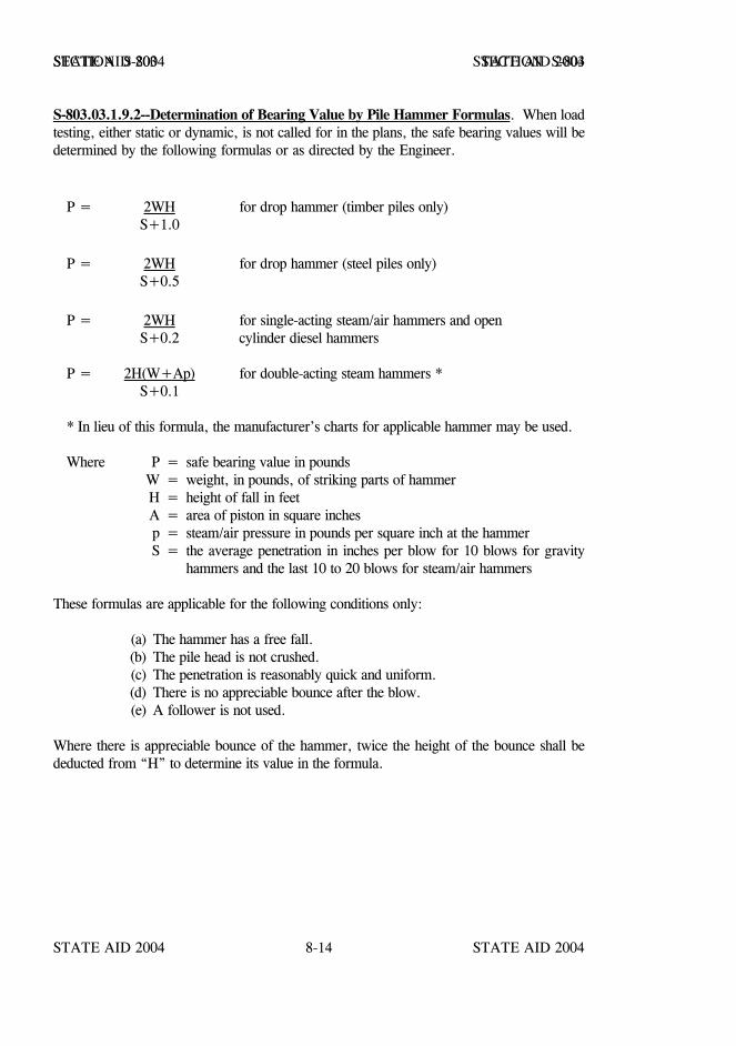
STATE AID 2004 STATE AID 2004
STATE AID 2004 STATE AID 20048-14
SECTION S-803 SECTION S-803
S-803.03.1.9.2--Determination of Bearing Value by Pile Hammer Formulas. When loadtesting, either static or dynamic, is not called for in the plans, the safe bearing values will bedetermined by the following formulas or as directed by the Engineer.
P = 2WH for drop hammer (timber piles only)S+1.0
P = 2WH for drop hammer (steel piles only)S+0.5
P = 2WH for single-acting steam/air hammers and openS+0.2 cylinder diesel hammers
P = 2H(W+Ap) for double-acting steam hammers *S+0.1
* In lieu of this formula, the manufacturer’s charts for applicable hammer may be used.
Where P = safe bearing value in poundsW = weight, in pounds, of striking parts of hammerH = height of fall in feetA = area of piston in square inchesp = steam/air pressure in pounds per square inch at the hammerS = the average penetration in inches per blow for 10 blows for gravity
hammers and the last 10 to 20 blows for steam/air hammers
These formulas are applicable for the following conditions only:
(a) The hammer has a free fall.(b) The pile head is not crushed.(c) The penetration is reasonably quick and uniform.(d) There is no appreciable bounce after the blow.(e) A follower is not used.
Where there is appreciable bounce of the hammer, twice the height of the bounce shall bededucted from “H” to determine its value in the formula.
STATE AID 2004 STATE AID 2004
STATE AID 2004 STATE AID 20048-15
SECTION S-803 SECTION S-803
When water jets are used, the bearing value shall be determined by the above formulas fromthe results of driving after the jets have been withdrawn, or a static or dynamic load test hasbeen conducted.
Formulas for pile hammers not covered herein must be approved by the State Aid BridgeEngineer.
S-803.03.1.9.3 Thru S-803.03.1.9.3.2.-- Blank
S-803.03.1.9.3.3- Restrike of Piling.
S-803.03.1.9.3.3.1--General. This method of bearing determination will only be used withprior approval of the State Aid Bridge Engineer. Restrikes shall be performed with a warmhammer operating at normal efficiency. A warm hammer is defined as a hammer that hasapplied a minimum of 20 blows to another pile or a dummy block immediately before beingused in a restrike. The restrike shall consist of striking the pile for 50 blows or until the pilepenetrates an additional three inches, whichever occurs first. In the event the pile movementis less than one inch after 15 blows during the restrike, the restrike may be terminated. Nopayment will be made for this procedure.
S-803.03.1.9.3.3.2--Blank
S-803.03.1.9.3.3.3--Blank
S-803.03.1.9.4--Determination of Bearing Value by Static Load Testing. When called forin the plans or directed by the Engineer, static load testing will be conducted to determine theultimate bearing capacity of piles. Depending upon the conditions encountered in the field, theState Aid Bridge Engineer may increase or decrease the number of static load tests required.
S-803.03.1.9.4.1–Blank.
S-803.03.1.9.4.2--Conventional Static Load Test.
S-803.03.1.9.4.2.1--Loading Test. Depending upon conditions encountered in the field, theState Aid Bridge Engineer may increase or decrease the number of loading tests required. Inthe event the number of loading tests are increased from that indicated in the contract,consideration will be given for delays, if any, in the applicable controlling phase of workcaused solely by the seven-day or other waiting period required by the Engineer. Anyadjustments will be in accordance with S-108.06.
STATE AID 2004 STATE AID 2004
STATE AID 2004 STATE AID 20048-16
SECTION S-803 SECTION S-803
These tests shall, in general, consist of a test load placed on a suitable platform supported bythe pile. A suitable apparatus for accurately measuring the test load and the settlement of thepile under each increment of load shall be provided. At the option of the Contractor, hydraulicjacks with suitable yokes, or other suitable hydraulic pressure systems with gages, may be usedin lieu of or in combination with platform loading.
S-803.03.1.9.4.2.2--Methods and Equipment. Apparatus for measuring the behavior of thepile during the test, whether tested by dead load or hydraulic pressure or combination, shallconsist of a measuring frame and two approved dial gage type measuring devices attached tothe pile as indicated on the plans. Each gage shall be actuated by its stem or by a stemattachment resting on the beam of the measuring frame. Supports for the measuring frameshall be placed the maximum practical distance from the test pile and the anchor piles. Eachdial gage shall be capable of providing measurements to an accuracy of 0.001 inch throughouta movement range of four inches and shall be sensitive to a force of one pound or less. Atleast one approved standby gage of each type used shall be provided at all times. TheContractor shall furnish a certification of the sensitivity and accuracy of each dial gage throughthe required range of use. The Engineer may require recertification of a gage at any time thereis an indication of inaccuracy. The Contractor shall provide adequate protection from theelements or from other damage to gages and other specified measuring devices duringhandling, transportation, and use so that inaccurate measurements or delays will not resultbecause of such damage.
S-803.03.1.9.4.2.3--Platform Method. When the dead load method for loading of the pileis used, the Contractor shall submit a loading plan and method for measuring the load to theEngineer for approval prior to its use. The method of dead loading shall be such that windloads will not effect the measured applied load.
Suggested methods for accomplishing this are:
A. Perform the load test when the wind is calm;
B. Support the dead load by a system which isolates it from the pile and use the deadload as the reaction device for hydraulic loading as provided herein; or
C. Any other approved method which will provide accurate measurement of the appliedload with adequate protection from wind effects.
STATE AID 2004 STATE AID 2004
STATE AID 2004 STATE AID 20048-17
SECTION S-803 SECTION S-803
S-803.03.1.9.4.2.4--Hydraulic Method. When the hydraulic pressure system method forapplying the test load is used, the Contractor shall furnish a hydraulic jacking system completewith gages and charts. The system shall include one or more hydraulic jacks in good conditionwithout leaks. The jacks shall be capable of applying the required load and shall have adequatepiston travel to compensate for the yield of the reaction facilities and the vertical displacementof the pile being tested.
The pressure gages shall have at least six-inch dials with 14-inch scales and twin-tip pointersor mirrored dials to permit accurate readings or at least eight-inch dials and 18-inch scales, inwhich case the mirror or twin-tip pointer will not be required. The gage shall accuratelyreflect the fluid pressure in the system within plus or minus one percent throughout the systemcapacity. Graduations on the gage shall be such that the applied load can be read directly inincrements of two percent or less, or shall be such that when read to the exact graduation andreferred to a certified calibration chart will provide a determination of the load being appliedwithin plus or minus one percent. Each gage shall contain a capacity for recalibration to zeroat zero pressure.
The complete hydraulic jacking system and gages shall be calibrated in accordance withAASHTO Designation: T 67, ASTM Designation: E-4, at least once, and pressure gages shallbe calibrated within one year preceding the time of use and whenever there is a reason to doubtthe accuracy of the results. If the laboratory performing the calibration uses a hydraulic testingmachine in lieu of the methods specified in AASHTO Designation: T 67 to apply the test load,the testing machine used to apply this load shall be calibrated in accordance with ASTMMethod E 74, and the report shall state that the testing machine had been calibrated by thismethod. Calibration shall include loading and unloading with the jacking system to determinethe hysteresis losses in the system. The calibration and certificate shall be made by a qualifiedtesting laboratory approved by State Aid, and the Engineer shall be furnished a report andcertificate of each calibration.
Systems containing two or more jacking pistons shall be approved by the Engineer before useand shall be subject to periodic calibration as determined by the Engineer.
S-803.03.1.9.4.2.5--Preparation for Loading. The Contractor shall provide means forpreventing eccentricity in the pile during loading, and shall be fully responsible for all loss ordamage caused by loading an eccentric pile or one which becomes eccentric during loading.
The pile to be load tested shall be installed as indicated on the plans to the specified tipelevation, or as directed. After the pile is in place, all loading devices shall be assembled intheir proper position. Before load is applied to the pile, the measuring frame shall beassembled and positioned with gages properly installed.
STATE AID 2004 STATE AID 2004
STATE AID 2004 STATE AID 20048-18
SECTION S-803 SECTION S-803
The head of the pile shall be normal to the longitudinal axis or shall be capped in such amanner as to produce a plane bearing surface normal to the longitudinal axis. When cut-offis necessary, the head of the pile shall be normal to the longitudinal axis or capped as above.A one-inch steel plate of the pile size or larger shall be set on top of the pile.
The jacking system shall include a reaction member of sufficient strength and support towithstand required loads. The reaction member shall be attached to anchor piles or shall beweighted by a loaded stationary box or platform resting on cribbing or other supports, or acombination of both. Anchor piles shall not be closer to the test pile than five times the greatestdimension of the largest pile driven; except for 18-inch or larger piles the State Aid BridgeEngineer may authorize in writing reaction piles at a closer interval, subject to the conditionsincluded in the authorization. The Contractor shall provide reaction facilities capable ofwithstanding at least two and one-half times the design load. All reaction facilities shall besubject to the approval of the Engineer with respect to possible adverse influence upon thebehavior of the test pile.
S-803.03.1.9.4.2.6--Application of Loads. Unless otherwise directed by the Engineer, a timeperiod of at least seven days shall elapse from the time the test pile and anchor piles, if used,are installed before the loading test is performed. During the required time lapse period, noother driving operations shall be performed within a 30-foot radius of the test pile, or a newseven-day period shall begin at the ending of the last pile driven within the 30-foot radius.
During the entire period that the test load or any portion thereof is on the pile, no pile drivingoperations, operation of heavy equipment, or any other operations shall be carried on withina distance, as determined by the Engineer, from the load test which might affect the behaviorof the loaded pile. In the event of such occurrence, or in the event of failure of the reactionfacilities or other loading and measuring equipment, the load test may be considered asdefective and unacceptable, and in the case of driven piles only an additional seven-day waitingperiod shall elapse before the loading test is resumed.
Failure to perform the load test on drilled and cast-in-place test piles in accordance with thesespecifications will result in an unacceptable load test. Additionally, the failed load test willinvalidate the test pile for further use and no payment will be allowed for the test pile or theload test.
STATE AID 2004 STATE AID 2004
STATE AID 2004 STATE AID 20048-19
SECTION S-803 SECTION S-803
Loads shall be applied in increments of 25 percent of the design load until a test load of 2 1/2times the design load has been maintained as provided herein, or until the Engineer suspendsthe loading because of obvious failure of the pile to carry the specified load. A guide fordetermining whether the pile has failed is as follows:
(A) For lengths of driven and cast-in-place concrete piles and timber piles upto 50 feet, a total top settlement of 1.0 inch and for lengths in excess of 50feet, a total top settlement of 1.5 inches. However, for cast-in-place piles,when skin friction is broken there may be some settlement due tocompression of relatively loose or bulked soil under the point of the pile,therefore the test must not be suspended until this possibility has been fullyconsidered. Any special effort by the Contractor in the drilling and castingthe test pile to prevent possible settlement from such cause shall beduplicated to the satisfaction of the Engineer for all piles represented by theload test.
(B) For steel piles and steel pile shells not filled with concrete up to 60 feet inlength, a total top settlement of 1.5 inches and for lengths in excess of 60feet, a total top settlement of 2.0 inches.
Each of the following loading conditions shall be applicable until the loading is completed orunless the Engineer has suspended the loading because of obvious failure of the pile:
a. Each loading increment, including the final increment, shall be maintainedfor a 15-minute period and for as many additional 15-minute periods, notto exceed two hours total time, as necessary to satisfy the conditions statedherein.
b. During the entire loading, readings are to be made at each five-minuteincrement of each 15-minute period and are to be made to the nearest 0.001inch.
c. When the settlement rate for the pile in the last five-minute increment of a15-minute period, averages less than 0.001 inch per minute, the nextincrement of load shall be applied.
d. When at the end of a 15-minute period, the settlement rate in the lastfive-minute increment averages more than 0.001 inch per minute, the loadincrement shall remain applied for the necessary successive 15-minuteperiods up to a total of two hours, after which the next increment of loadshall be applied.
STATE AID 2004 STATE AID 2004
STATE AID 2004 STATE AID 20048-20
SECTION S-803 SECTION S-803
e. The total load shall be maintained on the pile for two hours unless directed
otherwise directed by the Engineer.
a. The pile shall be unloaded in accordance with S-803.03.1.9.4.2.7.
S-803.03.1.9.4.2.7--Unloading and Measuring. Unless the loading has been suspended bythe Engineer, the pile shall be unloaded in decrements of 50 percent of the design load. Eachdecrement shall be maintained for a minimum of 15 minutes with settlement readings takenimmediately before and after its removal and at five-minute intervals. The final settlementreading shall be taken two hours after the removal of the last decrement of load and shall markthe conclusion of the loading test.
S-803.03.1.10--Pile Acceptance. The safe allowable load for each type and size of pile willbe as shown on the plans or as determined by the State Aid Bridge Engineer. Acceptancecriteria for the length of permanent production piles will be based on the recommended lengthsas determined by the State Aid Bridge Engineer from the test pile reports.
S-803.03.1.11--Test Piles. The Contractor shall furnish and install test piles of the sizes andtypes at the locations shown on the plans. It is the Contractor's responsibility to furnish testpiles of sufficient length to obtain the minium tip elevation and required bearing. Thisrequirement may necessitate test pile lengths in excess of that required to reach minimum tipelevation. The number of test piles may be increased or decreased by the State Aid BridgeEngineer as field conditions warrant. If determined by the State Aid Bridge Engineer to benecessary, test piles shall be extended, built-up, or spliced and in the case of steel piles drivenfurther. Similarly, the Contractor may be required to drive test piles below cut-off andextended as necessary.
S-803.03.2--Drilled Shafts.
S-803.03.2.1--Submittals.
S-803.03.2.1.1--Qualification of Contractor. The person(s) or firm directing the workdescribed in this specification shall be knowledgeable of drilled shaft installation proceduresand shall have installed drilled shafts of both diameter and length similar to those shown in theplans in accordance with the following minimum experience requirements:
(1) A drilled shaft Contractor shall have a minimum of three (3) years of drilledshaft installation experience prior to the bid date for this project; or,
(2) A Contractor without prior drilled shaft experience shall employ asuperintendent with a minimum of fifteen years of drilled shaft experienceprior to the bid date of this project.
STATE AID 2004 STATE AID 2004
STATE AID 2004 STATE AID 20048-21
SECTION S-803 SECTION S-803
A Contractor with limited drilled shaft installation experience may use a combination of theirexperience and the superintendent’s experience, with each five years of experience of thesuperintendent counting as equivalent to one year’s experience of the Contractor. A signedstatement listing the applicable work experience of the drilled shaft Contractor shall besubmitted to the Engineer at the Preconstruction Conference, or no later than 45 calendar daysprior to drilled shaft construction.
At the Preconstruction Conference, or no later than 45 calendar days prior to beginning drilledshaft construction, the Contractor shall furnish the Engineer evidence of the following:
(1) A signed statement from the drilled shaft superintendent responsible for thedrilled shaft installation that the project site has been visited, and that all thesubsurface information has been inspected. This information includes thesoil profiles and/or boring logs furnished in the plans, soil samples and rockcores, and the geotechnical investigation. All the above information maybe obtained from the Engineer.
(2) A signed statement from the drilled shaft Contractor detailing their abilityto complete a project of this type. This shall be supported by a listcontaining a detailed description of at least three (3) projects completed inthe last three (3) years on which the drilled shaft Contractor and/orsuperintendent has installed or supervised installation of drilled shaftssimilar in size to those shown in the plans, and utilized excavation methodssimilar to those anticipated for this project. This list of projects shallcontain names and phone numbers of the project owner’s representativeswho can verify the drilled shaft Contractor’s participation on the project,and the names of the superintendents who were in charge of the drilled shaftoperations.
(3) Name and experience records of the drilled shaft superintendent and drillerwho will perform the required work.
The Engineer will evaluate the evidence of qualifications submitted for conformance with thesespecifications. Should the information submitted be incomplete or not conform to the projectspecifications, the information will be rejected and the Contractor shall submit changes forreevaluation.
If the Contractor wishes to replace the drilled shaft superintendent or the driller during the lifeof the project, the name and experience record of their replacement shall be submitted to theEngineer for approval.
STATE AID 2004 STATE AID 2004
STATE AID 2004 STATE AID 20048-22
SECTION S-803 SECTION S-803
S-803.03.2.1.2--Drilled Shaft Installation Plan. At the Preconstruction Conference, or nolater than 45 calendar days before drilled shaft construction begins, the Contractor shall submitto the Engineer an installation plan for review. This plan shall provide information on thefollowing:
(1) A copy of the proposed drilled shaft concrete mix design as submitted withthe Contractor’s Concrete Quality Control Plan. Construction of the trialshaft(s) will not commence until the drilled shaft concrete mix design hasbeen approved in accordance with S-804.
(2) List and size of proposed equipment including cranes, drill rigs, augers,bits, bailing buckets, digging buckets, final cleaning equipment, slurrytanks, desanding equipment, slurry pumps, tremies, pump lines, concretepumps, casings, etc.
(3) Details of the method of exploration including the equipment, if required.
(4) Details of the sequence of construction operations and sequence of shaftconstruction within bents or shaft groups.
(5) Details of shaft excavation method(s).
(6) Details of slurry type and usage, including proposed methods to mix,circulate and desand slurry when slurry is required.
(7) Details of proposed methods to clean the drilled shaft excavation uponreaching the minimum required tip elevation.
(8) Details of reinforcement placement including the method of support whilealigning the cage for placement into the drilled shaft excavation and thecentering devices to be used to center the cage and assure minimum outsideclear space shown in the plans.
(9) Details of concrete placement including proposed operational procedures forconcrete tremie or pump, including initial placement, raising duringplacement, and overfilling of the shaft concrete, and the ability of theconcrete supplier to provide a continuous pour for the anticipated volumes.
(10) Details of casing installation and removal, when required.
(11) Details of any required load tests including equipment and recentcalibrations for any jacks supplied by the Contractor.
STATE AID 2004 STATE AID 2004
STATE AID 2004 STATE AID 20048-23
SECTION S-803 SECTION S-803
The Engineer will evaluate the Contractor’s Drilled Shaft Installation Plan for conformancewith the plans and specifications, after which the Engineer will notify the Contractor within 14calendar days of any additional information and/or changes that may be required. Any partof the plan that is unacceptable will be rejected and the Contractor shall submit changes forreevaluation.
All approvals given by the Engineer shall be subject to trial and satisfactory field performance,and shall not relieve the Contractor of the responsibility to satisfactorily complete the work asdetailed on the plans and in the specifications.
S-803.03.2.2--Trial Shaft Construction. The Contractor shall demonstrate the adequacy ofthe methods and equipment during construction of an out of position trial shaft. This trial shaftshall be positioned as far as practical from the production shafts, in the position shown on theplans or as directed by the Engineer, and shall be drilled to the minimum tip elevation asrequired on the plans. When shown on the plans, the reaming of bells at specified trial shaftswill be required to establish the feasibility of belling in a specific soil strata. Failure todemonstrate the adequacy of the Contractor's methods and equipment to construct the trialshaft shall be cause for the Engineer to require alterations in equipment and/or method by theContractor, to eliminate unsatisfactory results. Backfilling of unsuccessful excavations and anyadditional trial shafts required to demonstrate the adequacy of altered methods of constructionor equipment shall be performed by the Contractor at no additional cost to the Project. Oncethe Contractor has completed the excavation for the trial shaft to the satisfaction of theEngineer, the Contractor shall set the reinforcement and pour the concrete to finishconstruction of the trial shaft. This shall be demonstration that the entire plan for drilled shaftconstruction is satisfactory. Failure to successfully construct the trial shaft shall be cause forrejection of the trial shaft, and shall be reason for the Engineer to require alterations necessaryto eliminate unsatisfactory results. Additional trial shafts to demonstrate correction ofdeficiencies shall be at the Contractor's expense.
If differing soil conditions require two (2) or more methods for construction of productionshafts, said methods shall be demonstrated by trial shaft prior to construction of any productionshaft.
After the successful trial shaft has been completed, the Contractor shall submit in writing forreview the successful methods and equipment used. This submittal, once reviewed, will serveas the approved method of construction for all the production shafts covered by that successfultrial shaft. Once approval has been given to construct production shafts, no changes will bepermitted in the methods, equipment, drilled shaft superintendent, or driller from those usedduring the construction of the trial shaft without written approval of the Engineer.
Trial shafts shall be cut off two (2) feet below finish grade or two (2) feet below the mudlineand left in place. The portions of the shafts cut off and removed shall remain the property ofthe Contractor. The disturbed areas in the vicinity of the trial shaft shall be restored as nearlyas practical to their original condition.
STATE AID 2004 STATE AID 2004
STATE AID 2004 STATE AID 20048-24
SECTION S-803 SECTION S-803
S-803.03.2.3--Construction Methods and Equipment.
S-803.03.2.3.1--General.
S-803.03.2.3.1.1--Protection of Existing Structures. When the plans require drilled shaftexcavations within close proximity to existing structures or utilities, the Contractor shall takeall reasonable precautions to prevent damage to such structures. This shall include newlyconstructed shafts. If not otherwise provided for in the plans, the Contractor shall be solelyresponsible for evaluating the need for, design of, and providing all reasonable precautionaryfeatures to prevent damage. These measures shall include, but are not limited to, selectingconstruction methods and procedures that will prevent caving of the shaft excavation, andmonitoring and controlling the vibrations from construction activities, including the driving ofcasings, driving of sheeting, or from blasting, when permitted. Advancing an uncased drilledshaft excavation or the use of a vibratory hammer to install casings within 30 feet of a newlyconstructed shaft will not be permitted unless the concrete in that shaft has attained acompressive strength of 2500 p.s.i., as determined by cylinder tests. Based upon observations,the Engineer may adjust this distance accordingly. During shaft construction, the Contractorshall take into account and make provisions for vibrations caused by activities other than theContractor’s, such as adjacent traffic.
Such structures shall be monitored for settlement in an approved manner, recording elevationsto 0.01 foot. The number and location of monitoring points shall be as approved by theEngineer. Elevations shall be taken before construction begins, during the driving of anyrequired casings, and during excavation or blasting as directed by the Engineer.
When shown on the plans, or as directed by the Engineer, the Contractor shall monitor andrecord vibration levels during the driving of casings, sheeting, or during blasting operations.Vibration monitoring equipment shall be capable of detecting particle velocities of 0.1inch/second or less.
At any time the Contractor detects settlement of 0.03 foot, vibration levels reaching 1.5 inchesper second, or damage to the structure, the Contractor shall immediately stop the source ofvibrations, backfill the excavation, and contact the Engineer for instructions.
S-803.03.2.3.1.2--Construction Sequence for Site Preparation. Excavation to the planfooting elevation, if required, shall be completed before shaft construction begins. Anydisturbance to the footing area caused by shaft installation shall be repaired by the Contractorprior to the footing pour.
When drilled shafts are to be installed in conjunction with embankment placement, theContractor shall construct the drilled shafts after placement of the embankment material.
STATE AID 2004 STATE AID 2004
STATE AID 2004 STATE AID 20048-25
SECTION S-803 SECTION S-803
S-803.03.2.3.1.3--General Methods and Equipment. The Contractor shall perform theexcavations required for the shafts and bell footings, through whatever materials encounteredto the dimensions and elevations shown on the plans, or otherwise required by thespecifications, at no additional cost to the Project. The Contractor's methods and equipmentshall be suited for the intended purpose and the materials encountered.
Drilled shafts shall be constructed by either the dry method, wet method, casing method, orpermanent casing method, as necessary to produce a sound, durable, concrete foundation freeof defects. The permanent casing method shall be used only when required by the plans orauthorized by the Engineer. When the plans describe a particular method of construction, thismethod shall be used unless otherwise permitted by the Engineer. The Engineer may permitan alternate method than designated on the plans, only after successful construction of an outof position trial shaft. When the plans do not describe a particular method, the Contractor shallutilize a method on the basis of its suitability to the site conditions. Blasting shall only bepermitted if specifically stated on the plans or approved by the Engineer.
Once approval is given to construct production shafts, no changes will be permitted in themethods or equipment from those used in constructing the accepted trial shaft without writtenapproval of the Engineer.
S-803.03.2.3.2--Dry Construction Method. The dry construction method shall be used onlyat sites where the groundwater level and soil conditions are suitable to permit construction ofthe shaft in a relatively dry excavation, and where the sides and bottom of the shaft may bevisually inspected by the Engineer prior to placing the concrete. The dry method consists ofdrilling the shaft excavation, placing the reinforcing cage, and concreting the shaft in arelatively dry excavation.
The dry construction method shall be used only when the trial shaft excavation demonstratesthat: concrete can be placed with less than three (3) inches of accumulated water in the bottomof the shaft; the sides and bottom of the hole remain stable without caving, sloughing, orswelling over a two-hour period immediately following completion of the excavation; and anyloose material and excess water can be satisfactorily removed prior to inspection and prior toconcrete placement.
STATE AID 2004 STATE AID 2004
STATE AID 2004 STATE AID 20048-26
SECTION S-803 SECTION S-803
S-803.03.2.3.3--Wet Construction Method. The wet construction method shall be used atall sites where it is impractical to provide a dry excavation for placement of the shaft concrete.
The wet construction method consists of drilling the shaft excavation below the water table,keeping the shaft filled with water or mineral slurry, not a separate pay item, desanding orcleaning the slurry, final cleaning of the excavation by means of a bailing bucket, air lift,submersible pump or other approved devices, and placing the rebar cage and the shaftconcrete, with a tremie or concrete pump beginning at the shaft bottom, which displaces thewater or slurry as the shaft is concreted. Temporary surface casings shall be provided to aid shaft alignment and position and to prevent sloughingof the top of the shaft, except when the Contractor demonstrates to the satisfaction of theEngineer that the surface casing is not required.
Where drilled shafts are located in open water areas, the shafts shall be constructed by the wetmethod using casings extending from above the water elevation into the ground to protect theshaft concrete from water action during placement and curing of the concrete. The casing shallbe installed in a manner that will produce a positive seal at the bottom of the casing so thatthere is no intrusion or extrusion of water or other materials into or from the shaft excavation.Casings for this application may include multiple casings, temporary casings, and/or designedpermanent casings. The wet construction method may be used in combination with the drymethod and temporary or permanent casing methods.
S-803.03.2.3.4--Casing Construction Method. The casing construction method may be usedat sites when the dry or wet construction methods are inadequate to prevent hole caving orexcessive deformation of the hole. In this method, the casing may be either placed in apredrilled hole if no caving, swelling, or yielding occurs, or advanced through the ground bytwisting, driving, or vibration before being cleaned out.
When a formation is reached that is nearly impervious, a casing shall be placed in the hole andseated in the nearly impervious formation. Drilling may proceed as with the dry method to theprojected depth. If seepage occurs at this point, temporary casing may be advanced further tocreate the dry condition. In the event seepage conditions prevent use of the dry method,excavation shall be completed using wet methods. The placement of the concrete shall proceedas with the wet or dry method, except that the casing shall be withdrawn after the concrete isplaced.
When caving soils occur near the ground surface and/or if the top of the concrete for thedrilled shaft is below the ground surface, the Contractor shall set a suitable temporaryremovable surface casing. The minimum surface casing length shall be the length required toprevent caving of the surface soils and to aid in maintaining shaft position and alignment.Predrilling with slurry and/or overreaming to the outside diameter of the casing may beacceptable if required to install the surface casing at some sites.
STATE AID 2004 STATE AID 2004
STATE AID 2004 STATE AID 20048-27
SECTION S-803 SECTION S-803
Where drilling is through materials having a tendency to cave, the drilling shall be advancedby drilling in a mineral slurry. In the event that a caving layer or layers are encountered thatcannot be controlled by slurry, the Contractor shall install temporary removable casing throughsuch caving layer or layers. Overreaming to the outside diameter of the casing may berequired. However, the final dimensions of the drilled shaft shall not be altered toaccommodate these construction practices unless approved by the Engineer. The Contractorshall take whatever steps are required to prevent caving during shaft excavation includinginstallation of deeper casings. If the Contractor elects to remove a casing and replace it witha longer casing through caving soils, the Contractor shall adequately stabilize the excavationwith slurry or backfill the excavation. Other approved methods which will control the size ofthe excavation and protect the integrity of the foundation soils may be used to excavate throughcaving layers.
S-803.03.2.3.5--Permanent Casing Method. The permanent casing method shall be usedwhen required by the plans. In this method, a casing is driven to the prescribed depth beforeexcavation begins. If full penetration cannot be attained, the Contractor may excavate materialfrom inside the casing and the casing may be driven again until reaching the desiredpenetration. In some cases overreaming to the outside diameter of the casing may be requiredbefore driving the casing.
The casing shall be cut off at the prescribed elevation upon reaching the proper constructionsequence, and the remainder of the casing is left in place.
S-803.03.2.3.6--Excavation and Drilling Equipment. The excavation and drilling equipmentshall have adequate capacity including power, torque, and down thrust to excavate a hole ofboth the maximum diameter and to a depth 20 percent greater than the longest shaft shown onthe plans.
The excavation and overreaming tools shall be of adequate design, size, and strength toperform the work shown on the plans or described herein. When the material encounteredcannot be drilled using conventional earth augers with soil or rock teeth, drill buckets, and/orunderreaming tools, the Contractor shall provide special drilling equipment including but notlimited to: rock core barrels, rock tools, air tools, blasting materials, and other equipment asnecessary to construct the shaft excavation to size and depth required. Approval of theEngineer is required before excavation by blasting is permitted.
Sidewall overreaming shall be required when the sidewall of the hole is determined by theEngineer to have either softened due to excavation methods or delays in excavationcompletion, swelled due to delays in concreting, or degraded because of slurry cake build-up.Overreaming thickness shall be a minimum of 1/2 inch and a maximum of three inches beyondthe shaft radius. Overreaming may be accomplished with a grooving tool, overreamingbucket, or other approved equipment. The thickness and elevation of sidewall overreamingshall be as directed by the Engineer. The Contractor shall bear all costs associated with bothsidewall overreaming and additional shaft concrete placement.
STATE AID 2004 STATE AID 2004
STATE AID 2004 STATE AID 20048-28
SECTION S-803 SECTION S-803
S-803.03.2.3.7--Excavations.
S-803.03.2.3.7.1--General. Shaft excavations shall be made at locations and to the top ofshaft elevations, estimated bottom of shaft elevations, shaft geometry and dimensions shownin the plans. The Contractor shall extend drilled shaft tip elevations when the Engineerdetermines that the material encountered during excavation is unsuitable and/or differs fromthat anticipated in the design of the drilled shaft.
The Contractor shall maintain a drilling log during shaft excavation. The log shall containinformation such as: the description and approximate top and bottom elevation of each soil orrock strata, seepage or groundwater, and remarks. Three (3) copies of the final Contractor'slog shall be furnished to the Engineer at the time the drilled shaft is completed and accepted.
When shown on the plans, bells shall be excavated to form the height and bearing area of thesize and shape shown. The bell shall be excavated by mechanical methods. Any drilled shaftconcrete over the theoretical amount required to fill any excavations for the bells and shaftsdimensioned on the plans shall be furnished at no additional cost to the Project.
The Contractor shall not permit workmen to enter a shaft excavation for any reason unless:both a suitable size casing has been installed and the water level has been lowered andstabilized below the level to be occupied, and adequate safety equipment and procedures havebeen provided to workmen entering the excavation. The Contractor is responsible forcomplying with all State and Federal safety regulations.
S-803.03.2.3.7.2--Obstructions. Surface and subsurface obstructions at drilled shaft locationsshall be removed by the Contractor. Such obstructions may include man-made materials suchas old concrete foundations, and natural materials such as boulders. Special procedures and/ortools shall be employed by the Contractor after the hole cannot be advanced using conventionalaugers fitted with soil or rock teeth, drilling buckets and/or underreaming tools. Such specialprocedures/tools may include but are not limited to: chisels, boulder breakers, core barrels,air tools, hand excavation, temporary casing, and increasing the hole diameter. Blasting shallnot be permitted unless specifically approved in writing by the Engineer.
Drilling tools which are lost in the excavation shall be promptly removed by the Contractor atno cost to the Project. All costs due to lost tool removal shall be borne by the Contractorincluding, but not limited to, costs associated with hole degradation due to removal operationsor the time the hole remains open.
STATE AID 2004 STATE AID 2004
STATE AID 2004 STATE AID 20048-29
SECTION S-803 SECTION S-803
S-803.03.2.3.7.3--Exploration. When directed by the Engineer, the Contractor shall take soilsamples or rock cores to determine the character of the material directly below the completedshaft excavation. The soil samples shall be extracted with a standard penetration test splitspoon sampler or undisturbed sample (Shelby) tube. Rock cores, if required, shall be cut withan approved double or triple tube core barrel to a minimum of five (5) feet below the bottomof the drilled shaft excavation at the time the shaft excavation is approximately complete. Rockcore, undisturbed tube, and/or standard penetration test samples shall be measured, visuallyidentified, and described on the Contractor's log. The samples shall be placed in suitablecontainers, identified by shaft location, elevation, and project number, and delivered with theContractor's field log to the Engineer within 24 hours after the exploration is completed. TheEngineer will inspect the samples, or cores, and determine the final depth of requiredexcavation based on the evaluation of the material.
S-803.03.2.3.7.4--Excavation Completion. Concrete placement must begin within two (2)hours of completion of shaft excavation. If the drilled shafts are five (5) feet in diameter orlarger and in excess of sixty (60) feet in length, the elapsed time from completion of the drilledshaft excavation until beginning concrete placement may extend past two hours provided theexcavation remains stable and the extended time is demonstrated on the trial shaft. Completionof shaft excavation is defined as the time at which the specified tip elevation is initiallyachieved. Before concrete placement begins, bottom cleaning operations, any necessary slurrydesanding, and placement of the reinforcing steel must be completed. These operations areincluded in the two hour time limit.
When it becomes apparent, as the excavation of the shaft is nearing completion, that it will notbe feasible or possible to place concrete within the specified limit, the Contractor shall haltexcavation operations a minimum of five (5) feet above the specified tip elevation. In the eventthat the wet construction method is being used, the slurry should be desanded at this point sothat the remaining excavation will not cause the slurry to be too heavily contaminated and delayconcrete placement due to final desanding operations.
In no case shall any excavation within the bearing zone(s) be allowed to remain open and idlefor more than 24 hours. The bearing zone(s) are considered as those soil strata below thescour line, in the case of hydraulic structures, or those five feet below the ground line,whichever is greatest in depth. In no instance shall any uncased excavation, except for trialshafts, be allowed to remain open and idle for more than 24 hours. For partially completedexcavations which stand idle for more than six (6) hours but less than 24 hours, sidewalloverreaming may still be required by the Engineer.
STATE AID 2004 STATE AID 2004
STATE AID 2004 STATE AID 20048-30
SECTION S-803 SECTION S-803
If completion of shaft excavation has been achieved, and concrete placement has not begunwithin the specified limit, the Contractor shall backfill and/or stabilize the excavation. TheEngineer shall then direct the Contractor as to the additional shaft excavation that will berequired to produce a sound drilled shaft due to shaft wall and bottom degradation. The costof the additional excavation, concrete, reinforcing steel, and other incidentals will be borne bythe Contractor at no additional cost to the Project.
S-803.03.2.3.7.5--Casings.
S-803.03.2.3.7.5.1--General. Casings shall be steel, smooth, clean, watertight, and of amplestrength to withstand both handling and driving stresses and the pressure of both concrete andthe surrounding earth materials. The outside diameter of casing shall not be less than thespecified size of shaft. No extra compensation will be allowed for concrete required to fill anoversized casing or oversized excavations. All casings, except permanent casing, shall beremoved from the shaft excavation. Any length of permanent casing installed below the shaftcutoff elevations shall remain in place.
When the shaft is to extend above the ground or through a body of water, the portion exposedabove the ground or through a body of water may be formed with removable casing, exceptwhen permanent casing is specified. Removable casing shall be stripped from the shaft in amanner that will not damage the concrete. Casings can be removed when the concrete is curedfor a full 72 hours; the shaft concrete is not exposed to salt water or moving water for seven(7) days; and the concrete reaches a compressive strength of at least 2500 psi as determinedfrom concrete cylinder tests.
S-803.03.2.3.7.5.2--Temporary Casing. All subsurface casing shall be considered temporaryunless specifically shown as permanent in the contract documents. All temporary casing shallbe removed. Telescoping, predrilling with slurry, and/or overreaming to beyond the outsidediameter of the casing may be required to install the casing. When temporary casing largerthan called for on the plans is used for telescoping or overreaming, no additional compensationwill be made.
If the Contractor elects to remove a casing and substitute a longer or larger diameter casingthrough caving soils, the excavation shall be either stabilized with slurry or backfilled beforethe new casing is installed, as directed in S-803.03.2.3.4. Other methods, as approved bythe Engineer, may be used to control the stability of the excavation and protect the integrity ofthe foundation soils.
STATE AID 2004 STATE AID 2004
STATE AID 2004 STATE AID 20048-31
SECTION S-803 SECTION S-803
When temporary casings which are to be removed become fouled or bound in the shaftexcavation and cannot be practically removed, and concreting has not yet begun, the Engineermay direct that the shaft excavation be drilled deeper to compensate for the loss of capacity dueto the presence of the casing. No additional compensation will be paid for the casing left inthe excavation. No additional length of shaft will be paid for beyond the current depth ofexcavation or the plan tip elevation of the production shaft, whichever is lower.
Temporary casings which become bound or fouled during concreting of the shaft, and cannotbe practically removed before the concrete begins to set up, shall constitute a defect in thedrilled shaft. When the Engineer, in writing, notifies the Contractor of a defective shaft, theContractor shall be responsible for improving such defective shafts to the satisfaction of theEngineer. Improvements may consist of, but are not limited to, removing the shaft concreteand extending the shaft deeper to compensate for loss of frictional capacity in the cased zone,providing straddle shafts to compensate for capacity loss, proof load testing or providingreplacement shafts. All corrective measures, including redesign of footings or drilled shaftcaps, shall be performed to the satisfaction of the Engineer by the Contractor without eitheradditional compensation or extension of Contract Time. No compensation will be paid forcasing remaining in place. Any redesigns submitted must be approved in writing by the StateAid Bridge Engineer.
Temporary casing extraction shall be slow and uniform, pulling along the axis of the shaft.The elevation of the concrete in the casing shall be maintained high enough to displace thedrilling slurry between the outside of the casing and the edge of the hole as the casing isremoved. Temporary casings shall be removed while the concrete remains workable. Notemporary casings will be removed if the concrete slump is less than four (4) inches. Shouldthis condition occur, the shaft will be designated as defective, and corrections to the situationshall be as described above.
Special casing systems may be used in open water areas, when approved, which are designedto permit removal after the concrete has hardened. Special casings shall be designed so thatno damage occurs to the drilled shaft concrete during their removal. Any defects eithercosmetic or structural that are apparent after removal of the casing or are due to the removalof the casing shall be repaired to the satisfaction of the Engineer at no additional cost to theProject.
In the event that permanent casing is not specified in the plans, and the Contractor elects to usea temporary casing and leave it in place, it shall be cut off at a maximum of 12 inches abovethe low water elevation as shown on the plans, or painted. Written approval from theEngineer is required in this event, and payment for the temporary casing left in place will beat the contract bid price for temporary casing.
STATE AID 2004 STATE AID 2004
STATE AID 2004 STATE AID 20048-32
SECTION S-803 SECTION S-803
S-803.03.2.3.7.5.3--Permanent Casings. Permanent casing shall be used when shown on theplans. The casing shall be continuous between top and bottom elevations prescribed on theplans or as directed by the Engineer. Exterior surfaces of permanent casing shall be paintedin accordance with the plans unless otherwise noted. After installation is complete, thepermanent casing shall be cut off at the prescribed elevation and the shaft completed.
In general, permanent casing shall not be placed in an overreamed shaft hole.
S-803.03.2.3.8--Slurry. Mineral slurries shall be employed when slurry is used in the drillingprocess, unless other drilling fluids are approved in writing by the Engineer. The slurry shallhave both a mineral grain size that will remain in suspension and sufficient viscosity and gelcharacteristics to transport excavated material to a suitable screening system. The percentageand specific gravity of the material used to make the suspension shall be sufficient to maintainthe stability of the excavation and to allow proper concrete placement. During construction,the level of the slurry shall be maintained at a height sufficient to prevent caving of the hole.In the event there is a sudden, significant loss of slurry within the drilled shaft excavation, theconstruction of the drilled shaft shall be stopped until a method to stop slurry loss or analternate construction procedure has been approved by the Engineer.
Mineral slurry shall be premixed thoroughly with clean, fresh water, and an adequate time (asprescribed by the mineral manufacturer) shall be allotted for hydration, prior to introductioninto the shaft excavation. Slurry tanks of adequate capacity will be required for slurrycirculation, storage, and treatment. No excavated slurry pits will be allowed in lieu of slurrytanks, without the written permission of the Engineer. Desanding equipment shall be providedby the Contractor as necessary to control slurry sand content to less than two percent (2%) byvolume at any point in the borehole. Desanding will not be required for setting sign post orlighting mast foundations unless shown on the plans. The Contractor shall take all stepsnecessary to prevent the slurry from "setting up" in the shaft. Such methods may include, butare not limited to: agitation, circulation, and/or adjusting the properties of the slurry. Disposalof all slurry shall be performed offsite in suitable areas by the Contractor, and subject to allenvironmental regulations pertaining to slurry disposal.
Control tests using suitable apparatus shall be carried out on the mineral slurry mixture by aqualified individual or qualified professional testing laboratory approved by the Engineer.Tests to be conducted will be density, sand content, viscosity, and pH. The acceptable rangeof values for those physical properties is as shown in the following table:
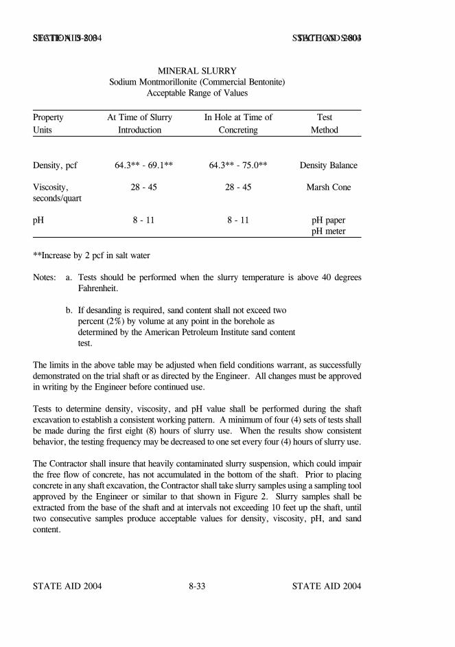
STATE AID 2004 STATE AID 2004
STATE AID 2004 STATE AID 20048-33
SECTION S-803 SECTION S-803
MINERAL SLURRYSodium Montmorillonite (Commercial Bentonite)
Acceptable Range of Values
Property At Time of Slurry In Hole at Time of TestUnits Introduction Concreting Method
Density, pcf 64.3** - 69.1** 64.3** - 75.0** Density Balance
Viscosity, 28 - 45 28 - 45 Marsh Coneseconds/quart
pH 8 - 11 8 - 11 pH paperpH meter
**Increase by 2 pcf in salt water
Notes: a. Tests should be performed when the slurry temperature is above 40 degreesFahrenheit.
b. If desanding is required, sand content shall not exceed twopercent (2%) by volume at any point in the borehole asdetermined by the American Petroleum Institute sand contenttest.
The limits in the above table may be adjusted when field conditions warrant, as successfullydemonstrated on the trial shaft or as directed by the Engineer. All changes must be approvedin writing by the Engineer before continued use.
Tests to determine density, viscosity, and pH value shall be performed during the shaftexcavation to establish a consistent working pattern. A minimum of four (4) sets of tests shallbe made during the first eight (8) hours of slurry use. When the results show consistentbehavior, the testing frequency may be decreased to one set every four (4) hours of slurry use.
The Contractor shall insure that heavily contaminated slurry suspension, which could impairthe free flow of concrete, has not accumulated in the bottom of the shaft. Prior to placingconcrete in any shaft excavation, the Contractor shall take slurry samples using a sampling toolapproved by the Engineer or similar to that shown in Figure 2. Slurry samples shall beextracted from the base of the shaft and at intervals not exceeding 10 feet up the shaft, untiltwo consecutive samples produce acceptable values for density, viscosity, pH, and sandcontent.
STATE AID 2004 STATE AID 2004
STATE AID 2004 STATE AID 20048-34
SECTION S-803 SECTION S-803
When any slurry samples are found to be unacceptable, the Contractor shall take whateveraction is necessary to bring the mineral slurry within specification requirements. Concreteshall not be poured until resampling and testing produce acceptable results.
Reports of all tests required above, signed by an authorized representative of the Contractor,shall be furnished to the Engineer on completion of each drilled shaft. The Engineer reservesthe right to perform comparison tests as determined necessary during mineral slurryoperations.
During construction, the level of mineral slurry in the shaft excavation shall be maintained ata level not less than four (4) feet above the highest expected piezometric pressure head alongthe depth of the shaft. If at any time the slurry construction method fails to produce thedesired final results, the Contractor shall discontinue this method and propose an alternatemethod for approval by the Engineer.
Drilling tools should contain vents to stabilize hydrostatic pressure above and below the toolduring extraction. The rate of tool extraction should not cause any noticeable turbulence in thehole.
In locations where saline or chemically contaminated groundwater exists, the slurry should beadjusted with appropriate chemical additives, or developed with a mineral material not affectedby such conditions.
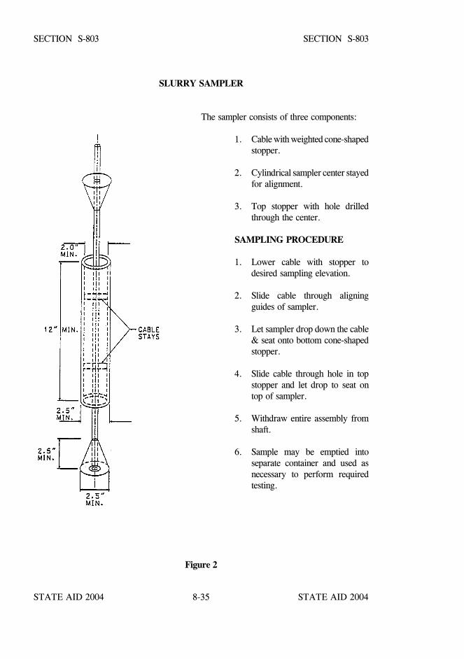
STATE AID 2004 STATE AID 2004
STATE AID 2004 STATE AID 20048-35
SECTION S-803 SECTION S-803
SLURRY SAMPLER
The sampler consists of three components:
1. Cable with weighted cone-shapedstopper.
2. Cylindrical sampler center stayedfor alignment.
3. Top stopper with hole drilledthrough the center.
SAMPLING PROCEDURE
1. Lower cable with stopper todesired sampling elevation.
2. Slide cable through aligningguides of sampler.
3. Let sampler drop down the cable& seat onto bottom cone-shapedstopper.
4. Slide cable through hole in topstopper and let drop to seat ontop of sampler.
5. Withdraw entire assembly fromshaft.
6. Sample may be emptied intoseparate container and used asnecessary to perform requiredtesting.
Figure 2

STATE AID 2004 STATE AID 2004
STATE AID 2004 STATE AID 20048-36
SECTION S-803 SECTION S-803
S-803.03.2.4--Excavation Inspection. The Contractor shall provide equipment for checkingthe dimensions and alignment of each drilled shaft excavation. The dimensions and alignmentshall be determined by the Contractor in the presence of the Engineer or the Engineer’sinspector. Final shaft depths shall be measured with a weighted tape or other approvedmethods after final cleaning. Unless otherwise stated on the plans, a minimum of 50 percentof the base of each shaft shall have less than 1/2 inch of sediment at the time of placement ofthe concrete. Shaft cleanliness will be determined by the Engineer, by visual inspection for dryshafts, or other methods deemed appropriate to the Engineer for wet shafts. In addition, fordry excavations, the maximum depth of water shall not exceed three (3) inches prior toconcrete pour.
S-803.03.2.5--Construction Tolerances. The following construction tolerances apply todrilled shafts unless otherwise stated in the contract documents.
(1) The drilled shaft shall be within three (3) inches of plan position in thehorizontal plan at the plan elevation for the top of the shaft.
(2) The vertical alignment of a vertical shaft excavation shall not vary from theplan alignment by more than 1/4 inch per foot of depth.
(3) After all the concrete is placed, the top of the reinforcing steel cage shall benot more than three (3) inches below plan elevation.
(4) All casing diameters shown on the plans refer to O.D. (outside diameter)dimensions. The dimensions of casings are subject to American PipeInstitute tolerances applicable to regular steel pipe. When approved, theContractor may elect to provide a casing larger in diameter than shown onthe plans.
(5) Bells shall be excavated to the plan bearing area and height shown on theplans as a minimum. The actual diameter of the bells shall not exceed three(3) times the specified shaft diameter. All other plan dimensions shown forthe bells may be varied, when approved, to accommodate the Contractor’sequipment.
(6) Top elevation of the shaft shall have a tolerance of plus one (1) inch orminus three (3) inches from the plan top of shaft elevation.
(7) Excavation equipment and methods shall be designed so that the completedshaft excavation will have a planar bottom. The cutting edges of excavationequipment shall be normal to the vertical axis of the equipment within atolerance of ±3/8 inch per foot of shaft diameter.
STATE AID 2004 STATE AID 2004
STATE AID 2004 STATE AID 20048-37
SECTION S-803 SECTION S-803
Drilled shaft excavations and completed shafts not constructed within the required tolerancesare unacceptable. The Contractor shall be responsible for correcting all unacceptable shaftexcavations and completed shafts to the satisfaction of the Engineer. Materials and worknecessary, including engineering analysis and redesign, to complete corrections for out oftolerance drilled shaft excavations shall be furnished without either cost to the Project or anextension of the completion dates of the project. Any redesign shall be performed by aprofessional engineer, registered in the State of Mississippi and engaged by the Contractor.Redesign drawings and computations prepared by the Contractor's engineer shall be signed andsealed.
Out of tolerance shaft holes shall be backfilled in an approved manner, when directed by theEngineer, until the redesign is complete and approved.
S-803.03.2.6--Reinforcing Steel Construction and Placement. The reinforcing steel cage,consisting of longitudinal bars, ties, cage stiffener bars, spacers, centralizers, and othernecessary appurtenances, shall be completely assembled and placed as a unit immediately afterthe shaft excavation is inspected and accepted, and prior to concrete placement. Details ofreinforcing steel will be as shown in the plans.
The reinforcing steel in the shaft shall be double-wire tied at all junctions and supported so thatthe reinforcing steel will remain within allowable tolerances given in S-803.03.1.5.1. Stiff tiewire may be required for long reinforcing steel cages. Free-rolling concrete centralizers orother approved noncorrosive rolling centralizer devices shall be used at sufficient intervals.The centralizers shall be attached to the reinforcing steel cage near the bottom, and at intervalsnot exceeding 10 feet up the shaft for shaft lengths less than 60 feet, and intervals notexceeding seven (7) feet for shaft lengths greater than 60 feet, to insure concentric spacingfor the entire cage length. Centralizers shall be constructed of approved material equal inquality and durability to the concrete specified for the shaft. The centralizers shall be ofadequate dimension to insure a minimum five (5) inch annular space between the outside of thereinforcing cage and the side of the excavated hole. Approved cylindrical feet (bottomsupports) shall be provided to insure that the bottom of the cage is maintained the properdistance above the base.
The elevation of the top of the steel cage shall be checked before and after the concrete isplaced. If the rebar cage is not maintained within the specified tolerances, corrections shall bemade by the Contractor to the satisfaction of the Engineer. No additional shafts shall beconstructed until the Contractor has modified the rebar cage support in a manner satisfactoryto the Engineer.
If the bottom of the excavated shaft elevation is lower than the bottom of the shaft elevationshown on the plans, all reinforcement required in the upper portion of the shaft shall beachieved by splicing the additional length at the bottom of the cage, to avoid congestion in theupper portion of the shaft.
STATE AID 2004 STATE AID 2004
STATE AID 2004 STATE AID 20048-38
SECTION S-803 SECTION S-803
S-803.03.2.7--Concrete Placement.
S-803.03.2.7.1--General. Drilled Shaft concrete shall meet the requirements in S-804.
Concrete placement during cold weather shall be allowed when ambient air conditions are ator expected to drop below 40oF, but protection of the fresh concrete shall be in accordancewith the provisions stated in S-804. The Contractor shall assume all responsibility forprotection of fresh concrete in cold weather.
Concrete shall be placed as soon as possible after reinforcing steel placement. Concreteplacement shall be continuous from the bottom to the top elevation of the shaft. Concreteplacement shall continue after the shaft excavation is full until good quality concrete is evidentat the top of the shaft. Concrete shall be placed either through a tremie, concrete pump or freefall. Free fall placement shall require prior written approval of the Engineer and shall berestricted for use in dry excavations only.
For tremied or pumped concrete, the elapsed time from the beginning of concrete placementin the shaft to the completion of the placement shall not exceed four (4) hours, except as notedbelow. Retarders and/or water reducers in the concrete mix shall be adjusted as approved forthe conditions encountered on the job, so that the concrete remains in a workable plastic statethroughout the four hour placement limit. This is defined as a minimum slump of four (4)inches existing everywhere within the concrete shaft after placement has been completed. Priorto concrete placement, the Contractor shall provide test results of a trial mix, set time test perAASHTO Designation: T 197, and a slump loss test using approved methods, to demonstratethat the concrete meets this four hour requirement. These tests shall be conducted by anapproved testing laboratory at least 30 days prior to initial concrete placement, with theMDOT’s Central Laboratory personnel or other approved Laboratory personnel present, attemperatures and conditions similar to those at the job site at the time of the shaft pour.However, the Contractor may request a longer placement time, provided a concrete mix issupplied that will maintain a slump of four (4) inches or greater over the longer placementtime, as demonstrated by trial mix, set time, and slump loss tests. A slump loss test shall beconducted from the concrete at the site for verification of slump loss requirements, using asample from a minimum batch size of four cubic yards of concrete.
In the event that free-fall concrete placement is approved and used, the four inch slump in fourhours requirement will be waived. However, a different trial mix must be approved with itscorresponding set time and slump loss tests.
The Contractor shall place the concrete within the approved time and temperature limitationsdetermined by the trial mix demonstration.

STATE AID 2004 STATE AID 2004
STATE AID 2004 STATE AID 20048-39
SECTION S-803 SECTION S-803
Before the casing is withdrawn, the level of fresh concrete shall be at such a level that the fluidtrapped behind the casing is displaced upward. As the casing is withdrawn, care shall beexercised to maintain the level of concrete within the casing so that the fluid trapped behind thecasing is displaced upward out of the shaft excavation without mixing with or displacing theshaft concrete.
S-803.03.2.7.2--Tremies. Tremies used for concrete placement in either wet or dryexcavations shall consist of a tube of sufficient length, weight, and diameter to dischargeconcrete at the shaft base elevation. The tremie shall not contain aluminum parts which willhave contact with the concrete. The tremie inside diameter shall be at least six (6) times themaximum size of aggregate used in the concrete mix but shall not be less than 10 inches. Theinside and outside surfaces of the tremie shall be clean and smooth to permit both flow ofconcrete and unimpeded withdrawal during concreting. The wall thickness of the tremie shallbe adequate to prevent crimping or sharp bends which restrict concrete placement.
The tremie used for wet excavation concrete placement shall be watertight. Underwaterplacement shall not begin until the tremie is placed at the bottom of the excavation. Valves,bottom plates, or plugs may be used only if concrete discharge can begin within one tremiediameter of the base. Plugs and plates shall either be removed from the excavation or be ofa material, approved by the Engineer, which will not cause a defect in the shaft if notremoved. The discharge end of the tremie shall be constructed to permit the free radial flowof concrete during placement operations. The tremie discharge end shall remain at theexcavation bottom as long as possible, and thereafter be immersed at least two shaft diametersbut not less than 10 feet in concrete at all times after starting the flow of concrete. The flowof concrete shall be continuous. The concrete in the tremie shall be maintained at a positivepressure differential at all times to prevent water or slurry intrusion into the shaft concrete.
If, at any time during the concrete pour in a wet excavation, the tremie line orifice is removedfrom the fluid concrete column and discharges concrete above the rising concrete level, theshaft shall be considered defective. In such case, the Contractor shall remove the reinforcingcage and concrete, complete all necessary sidewall removal directed by the Engineer andrepour the shaft. All costs of replacement of defective shafts shall be the responsibility of theContractor.
S-803.03.2.7.3--Pumping Concrete. Concrete pumps and lines may be used for concreteplacement in either wet or dry excavations. All pump lines shall have a minimum five (5) inchdiameter and be constructed with watertight joints. The use of aluminum pipe as a conveyancefor the concrete will not be permitted. Concrete placement shall not begin until the pump linedischarge orifice is at the bottom of the excavation.
For wet excavations, a plug or similar device shall be used to separate the concrete from thefluid in the hole until pumping begins. The plug shall either be removed from the excavationor be of a material, approved by the Engineer, which will not cause a defect in the shaft if notremoved.
STATE AID 2004 STATE AID 2004
STATE AID 2004 STATE AID 20048-40
SECTION S-803 SECTION S-803
The discharge orifice shall remain at least two shaft diameters but not less than 10 feet belowthe surface of the fluid concrete at all times after starting the flow of concrete. When liftingthe pump line during concreting, the Contractor shall temporarily reduce the line pressure untilthe orifice has been repositioned at a higher level in the excavation.
If, at any time during the concrete pour, the pump line orifice is removed from the fluidconcrete column and discharges concrete above the rising level, the shaft shall be considereddefective. In such case, the Contractor shall remove the reinforcing cage and concrete,complete all necessary sidewall removal directed by the Engineer and repour the shaft. Allcosts of replacement of defective shafts shall be the responsibility of the Contractor.
S-803.03.2.7.4--Free Fall Method. Placement of concrete by the free fall method will bepermitted only when approved in writing by the Engineer. Approval of concrete placementby the free fall method shall be contingent upon the following conditions:
(1) The clear opening inside the reinforcing cage is not less than 24 inches indiameter.
(2) The dry construction method is used in constructing the drilled shafts.
(3) The height of free fall placement shall not exceed 75 feet.
(4) Concrete shall fall directly to the placement location without contactingeither the reinforcing cage or shaft walls.
(5) A hopper shall be used at the top of the shaft to center and direct free fallplacement.
(6) The Engineer will observe the falling of the concrete within the shaft. TheContractor shall reduce the rate of concrete placement or reduce the heightof free fall as directed by the Engineer when the concrete strikes thereinforcing cage or shaft sidewalls, when there is excessive spatter from theimpact of the falling concrete, or when concrete placement causes the shaftexcavation to cave or slough.
(7) When in the opinion of the Engineer, placement cannot be satisfactorilyaccomplished by the free fall method, the Contractor shall change to eitherthe tremie or pumping method to accomplish the pour.
STATE AID 2004 STATE AID 2004
STATE AID 2004 STATE AID 20048-41
SECTION S-803 SECTION S-803
S-803.03.2.8--Drilled Shaft Load Tests. The methods required for the load testing of drilledshafts shall be Static and/or Static with Special Instrumentation. Load testing of drilled shaftsshall be completed before construction of any production drilled shafts, and the results used bythe Engineer to determine the drilled shaft lengths given on the order list. The method,number, and locations of load tests shall be as shown on the plans or as designated by theEngineer.
After completion of any load test, the order list providing the final production lengths will beprovided within two weeks of receiving the load test results. The production shaft lengthsprovided by the Engineer may differ from the individual shaft lengths shown on the plans.Requests for adjustment to the contract due to changes in shaft lengths shall be subject to theprovisions of S-104.02.1. Before any consideration will be given for an adjustment to thecontract, it must be determined that a significant change in the character of the work hasoccurred.
S-803.03.2.8.1--Static Load Tests. Static load testing shall not begin until the concrete hasattained a compressive strength of 3000 psi as determined from cylinder tests. During thecuring time, no other construction or operations which will induce excessive vibration levels,as previously discussed, shall be performed.
Static axial load tests shall be performed by personnel of the Geotechnical Branch of MDOTor other approved Lab assisted by the Contractor’s personnel using the procedures as describedin ASTM Designation: D 1143, quick test method. No weighted platforms to totally supply theaxial load are allowed.
The Contractor shall be responsible for furnishing the following:
(1) A reaction frame capable of resisting a total load of at least four (4) timesthe design load of the test shaft shall be provided. The frame shall consistof a beam(s) or girder(s) that will carry the required load while sustainingonly minor deflections in the reaction system. The beam or girder shall beattached to a system of anchor shafts or piles. The anchor piles shall not becloser than three (3) diameters measured from the center of the test shaft.
(2) A hydraulic jack that has been calibrated for the full range of anticipatedloads in accordance with AASHTO Designation: T 67 (ASTM Designation:E 4) at least once. The maximum anticipated load shall be assumed to befour (4) times the design load for the test shaft. The pressure gage shall becalibrated within one year preceding time of use. The Contractor shallfurnish a certificate of calibration for the hydraulic jack at the time of loadtesting.
STATE AID 2004 STATE AID 2004
STATE AID 2004 STATE AID 20048-42
SECTION S-803 SECTION S-803
(3) A measuring frame or reference beam for measuring the movement of thetest shaft during testing. Two dial gages, supplied by the Contractor, willbe attached to the test shaft during testing to monitor downward movement.Each dial gage will be actuated by its stem or by a stem attachment restingon the measuring frame. The supports for the measuring frame shall beplaced the maximum practical distance from the test pile and the anchorshafts or piles. In no case shall the measuring frame be affected bymovement of the test shaft or the anchor shafts or piles.
The Contractor will furnish the load cell, gages, any needed details of the shaft gage locationsand personnel to run the test. The MDOT Geotechnical Branch or other approved Lab shallbe responsible for reviewing and submitting the results to the Engineer. The Contractor shallsubmit a detailed plan for any jacks and load frame to the Engineer for evaluation. This planshould include the following:
(1) Size and type of the reaction beam or beams.
(2) Size, type, number, and length of reaction piles or shafts.
(3) Type and capacity of any jacks and their most recent calibration documents.
(4) A plan sheet shop drawing showing plan and profile of load frame details.Details should be shown for of how the reaction beam will be connected tothe reaction piles or shafts. A detail showing how the jack, load cell (6”height, 11” diameter, supplied by the Contractor), and bearing plates areto be arranged between the shaft top and the bottom of the reaction beam.
(5) Details of a protected work area, including provisions such as a tent or shedfor protection from inclement weather for the testing equipment, of a sizeand type required by the Engineer.
After testing is completed, the test shafts and any anchor shafts shall be cut off at an elevationtwo (2) feet below the finished ground surface. The portion of the shafts cut off and removedshall remain the property of the Contractor.
STATE AID 2004 STATE AID 2004
STATE AID 2004 STATE AID 20048-43
SECTION S-803 SECTION S-803
S-803.03.2.8.2--Load Testing of Drilled Shafts With Special Instrumentation.
S-803.03.2.8.2.1--General. When designated on the plans, a dedicated test shaft shall beconstructed as detailed in the plans with instrumentation and hydraulic jack(s) cast in theconcrete of the drilled shaft. The Contractor will be required to furnish all materials,equipment, labor, and incidentals necessary for conducting the load test and reporting theresults. The Contractor shall subcontract the instrumenting, conducting, and reporting of theload test to the company supplying the instrumentation with the cost included in prices bid fortest shaft.
No reaction systems and extra drilled shaft installations such as anchor shafts are required forconducting the load test. The load test is a non-destructive test, and if the test shaft designatedon the plans is a production shaft, it shall be left in a condition suitable for use as a productionshaft in the finished structure.
S-803.03.2.8.2.2--Materials. When called for in the plans, instrumentation shall be suppliedto meet the requirements set forth in the plans. Instrumentation required in the plans aresubject to prior approval by the Engineer. Additional equipment that may be required is asfollows.
(1) Materials sufficient to construct a stable reference beam system formonitoring deflection of the shaft during testing, supported at a minimumdistance of three (3) diameters from the center of the shaft to preventdisturbance of the reference system.
(2) Materials sufficient to construct a protected work area, including provisionssuch as a tent or shed for protection from inclement weather for the loadtest equipment, of size and type required by the Engineer.
Materials supplied which do not become a part of a finished structure shall be removed fromthe job site at the conclusion of the load test.
S-803.03.2.8.2.3--Equipment. The Contractor shall supply any additional equipment requiredto install the testing instrumentation and conduct the load test, remove the load test apparatus,and, if the test shaft is to become a production shaft at the conclusion of the test, restore theshaft to a condition suitable for use in the finished structure. This equipment includes, but isnot limited to:
(1) Electric power and welding equipment, as required, to assemble the testequipment, instrumentation, and prepare the work area.
(2) A suitable pressurized gas source consisting either of an approved aircompressor or of compressed nitrogen, i.e. four 230 cubic-foot cylinders ofnitrogen per load test.

STATE AID 2004 STATE AID 2004
STATE AID 2004 STATE AID 20048-44
SECTION S-803 SECTION S-803
(3) Equipment and operators for handling the instrumentation and reinforcingcage, if required, during the installation of the test shaft and during the test.This shall include, but is not limited to, a crane or other lifting device,manual labor, and hand tools.
(4) Equipment and labor sufficient to erect the protected work area andmonitoring reference beam system, to be constructed to the requirements ofthe Engineer and instrumentation supplier.
(5) Approved small piston type power grout pump with experienced operator,for grouting the cell upon completion of the test if required. Successfuldemonstration that the grout pumping system works as intended will berequired before placing the instrumentation in the test shaft hole.
(6) Approved small power mortar mixer with suitable mortar box to dischargegrout, if required, with an experienced operator.
(7) Screen with an approximately 1/4-inch mesh to screen grout prior toplacement in the grout pump to prevent clogging of the grout pump or thepiping.
(8) Suitable operating and reference level platforms, as required by theEngineer and/or instrumentation supplier, for testing over water or inotherwise unstable foundation conditions.
S-803.03.2.8.2.4--Procedure. The test shaft shall be constructed by the shaft constructiontechnique approved by the Engineer after trial shaft construction. The test shaft shall then beconstructed in accordance with the plans and at the direction of the Engineer.
The instrumentation shall be assembled and made ready for installation under the direction ofthe instrumentation supplier, in a suitable area, adjacent to the test shaft, to be provided by theContractor. When a reinforcing cage is required for the test shaft, the instrumentation shall beplaced as directed in the plans.
When the test shaft excavation has been completed and accepted by the Engineer, theContractor shall then install the instrumentation and, if required, the reinforcing cage assemblyin the test shaft under the direction of the Engineer. The Contractor shall use the utmost carein handling the reinforcing cage and test equipment assembly so as not to damage theinstrumentation during installation.
STATE AID 2004 STATE AID 2004
STATE AID 2004 STATE AID 20048-45
SECTION S-803 SECTION S-803
After the installation of the instrumentation, the test shaft shall be concreted in the mannerapproved from the trial shaft construction. Load testing shall not begin until the concrete hasattained a compressive strength of 3000 psi as determined from cylinder tests. During thecuring period, no other construction or operations which will induce excessive vibration levelsshall be performed.
After completion of the load test, and at the direction of the Engineer, the Contractor shallremove any equipment, material, etc. which are not to be a part of the finished structure.
The Contractor shall supply the Engineer with six (6) copies of the final load test report.
S-803.04--Method of Measurement.
S-803.04.1--Test Piles. Test piles will be measured per each complete-in-place. Pilesmeasured as test piles will not be included in the measurement of pay footage for permanentpiles.
Test piles constructed in accordance with the lengths indicated on the plans and which arerequired to be extended or built up will be measured as a percentage, calculated by dividingthe sum of the plan length plus the length of the ordered extension or build-up, by the planlength. Splices required for the extension(s) will not be measured for payment. Nomeasurement for payment will be made for cut-off of a test pile.
S-803.04.2--Conventional Static Pile Load Tests. Conventional static pile load tests will bemeasured by the actual number of static load tests conducted on either a test pile or permanentproduction pile in accordance with these specifications.
In the event a pile is reloaded in accordance with these specifications, the reloading will bemeasured for payment as 50 percent of a separate conventional static pile load test.
S-803.04.3--Pile Shoes. Pile shoes of approved design, ordered and used, will be measuredand paid as set out in S-803.05.3.
S-803.04.4--Piling. Piling, exclusive of those measured as test piles, will be measured by thelinear foot for each class and size of piling furnished and installed in accordance with lengthsshown on the plans or approved by the State Aid Bridge Engineer. Cut-offs for eachindividual pile will be measured and deducted as set forth in S-803.04.5.
Pile lengths in excess of those shown on the plans or approved by the State Aid BridgeEngineer will not be measured for payment unless such additional lengths below cut-off areapproved in writing by the State Aid Bridge Engineer for incorporation in the structure.
STATE AID 2004 STATE AID 2004
STATE AID 2004 STATE AID 20048-46
SECTION S-803 SECTION S-803
S-803.04.5--Cut-Off. The summation of all cut-offs shall be deducted at 50 percent todetermine the length for payment of in-place permanent piling.
The summation of all cut-offs for pile lengths in excess of those shown on the plans orapproved by the State Aid Bridge Engineer will be deducted at 100 percent to determine thelength for payment of in-place permanent piling.
An allowance will be made for prestressed concrete piling cut-offs in accordance with theprovisions of S-803.05.5. Cut-offs shall be measured for payment per each for each pilerequiring cut-off. All piling cut-offs shall become the property of and shall be disposed of bythe Contractor.
S-803.04.6--Extensions or Build-Ups. Extensions or build-ups will not be measured forpayment as such, but will be included in the length of piling remaining in the finishedstructure. In determining the amount to be included in piling footage, no allowance will bemade for cut-offs necessary to accomplish the extensions or build-ups.
S-803.04.7--Falsework and Defective Piles. No allowance will be made for furnishing ordriving of falsework piles, for piles driven out of place, for defective piles, or for piles whichare damaged by handling or driving.
S-803.04.8--Splices. Splices necessary for extensions or build-ups on bearing piles will bemeasured by the linear foot. For prestressed concrete piles, the number of linear feet will bedetermined by allowing seven linear feet of piling for each splice. For other piles, the numberof linear feet will be determined by allowing four linear feet of piling for each splice. The totalnumber of linear feet of piling to be paid for shall be determined by adding seven feet or fourfeet, as applicable, to the net length of piling for each splice in place in the finished structure.
No measurement or payment will be made for splices except those made at the direction andunder the supervision of the Engineer.
S-803.04.9--Pre-formed Pile Holes. Pre-formed pile holes, when included as a pay item onthe plans, will be measured by the linear foot. For trestle type bents, the footage for each holewill be determined by subtracting the elevation of the bottom of the hole shown on the itemizedlist from the elevation of the natural ground at the pile site or from the elevation of theexcavated section, whichever is lower. For foundations and end bents, the footage will bedetermined by subtracting the elevation of the bottom of the hole as shown on the itemized listfrom the elevation of the bottom of the footing or the bottom of the end bent caps, asapplicable.
S-803.04.10 thru S-803.04.12–Blank.
STATE AID 2004 STATE AID 2004
STATE AID 2004 STATE AID 20048-47
SECTION S-803 SECTION S-803
S-803.04.13--Pile Restrike. The pile restrike will be conducted as directed by the Engineerfor bearing determination on permanent or test piles and no additional compensation will beallowed.
S-803.04.14--Drilled Shaft. Drill shaft will be measured per linear foot. Measurement shallbe the authorized length in feet of the completed concrete drilled shaft, including bells, of thediameter and containing the reinforcement shown on the plans. The length shall be determinedas the difference between the plan top of shaft elevation and the final bottom of shaft elevation.
S-803.04.15--Test Shaft. Test shaft of the specified diameter will be measured per each.Such measurement shall be full compensation for excavating the test shaft through whatevermaterials are encountered to the bottom of the shaft elevation shown on the plans or asauthorized by the Engineer, concrete, reinforcement, required casings, special instrumentationload cell when required, conducting and reporting load test results, restoring the site asrequired, and all other expenses to complete the work.
S-803.04.16--Trial Shaft. Trial shaft of the specified diameter will be measured per linearfoot. Such measurement shall be full compensation for excavating the trial shaft hole throughwhatever materials are encountered to the bottom of shaft elevation shown on the plans or asauthorized by the Engineer, using mineral slurry as necessary, utilizing temporary casing asnecessary which is not a separate pay item, providing inspection facilities, backfilling the holes,setting reinforcement and placing concrete as required, restoring the site, and all otherexpenses necessary to complete the work.
S-803.04.17--Exploration. Exploration will be measured per linear foot of soil samplesand/or rock cores of the diameter and length required and authorized by the Engineer. Suchmeasurement shall be full compensation for drilling, extracting, packaging and classifying thesamples or cores, delivering them to the MDOT Lab or other approved Lab, furnishingconcrete to fill the core hole, and all other expenses necessary to complete the work.
S-803.04.18--Casing. Casing shall be measured per linear foot. Such measurement shall befull compensation for furnishing, placing, and removing when required, the casing in the shaftexcavation.
S-803.05--Basis of Payment.
S-803.05.1--Test Piles. Test piles, measured as prescribed above, will be paid for at thecontract unit price per each.
S-803.05.2--Conventional Static Pile Load Tests. Conventional static pile load tests,measured as prescribed above, will be paid for at the contract unit price per each.

STATE AID 2004 STATE AID 2004
STATE AID 2004 STATE AID 20048-48
SECTION S-803 SECTION S-803
S-803.05.3--Pile Shoes. If not covered by a contract item or otherwise required by the plans,metal shoes ordered by the Engineer will be paid for at double the invoice cost of the shoe.The cost of placing the pile shoes and driving piling with these additional requirements will notbe paid for directly, and the cost thereof shall be considered incidental to the respective piledriving pay item.
S-803.05.4--Piling. Piling of the type specified will be paid for at the contract unit price perlinear foot.
S-803.05.5--Cut-Offs. For permanent prestressed concrete piles required to be cut off and thecut-offs are not necessitated by damage to the pile or as a result of a pile furnished in a lengthgreater than that established by the pile list on the plans or furnished by the State Aid BridgeEngineer, the Contractor will be paid $60.00 per each pile cut-off for sizes smaller than 20inches and $80.00 per each pile cut-off for sizes 20 inches and larger.
S-803.05.6--Extensions or Build-Ups. Extensions or Build-ups will not be paid for directly,but will be included in payment for piling. No payment will be made for extensions orbuild-ups for test piles.
S-803.05.7--Blank.
S-803.05.8--Splices. Splices, measured as per S-803.04.8, will be paid for at the contract unitprice per linear foot for the particular type pile splices.
S-803.05.9--Pre-formed Pile Holes. Pre-formed pile holes of the sizes specified will be paidfor at the contract unit price per linear foot.
S-803.05.10 thru S-803.05.12-- Blank.
S-803.05.13--Pile Restrike. Pile restrikes, will not be paid for.
S-803.05.14--Drilled Shafts. Drilled shafts of the type specified, measured as prescribedabove, will be paid for at the contract unit price per linear foot, which price shall include thecost of concrete, reinforcing steel, and all labor, materials including mineral slurry, equipment,and incidentals necessary to complete the drilled shaft.
S-803.05.15--Test Shafts. Test shafts of the type specified, measured as prescribed above,will be paid for at the contract unit price per each, which price shall be full compensation forexcavating the test shaft through whatever materials are encountered to the bottom of the shaftelevation shown on the plans or as authorized by the Engineer, concrete, reinforcement,required casings, special instrumentation load cell if required, conducting and reporting loadtest results, restoring the site as required, and all other expenses to complete the work.
STATE AID 2004 STATE AID 2004
STATE AID 2004 STATE AID 20048-49
SECTION S-803 SECTION S-803
S-803.05.16--Trial Shaft. Trial shafts of the type specified, measured as prescribed above,will be paid for at the contract unit price per linear foot, which price shall be full compensationfor excavating the trial shaft through whatever materials are encountered to the bottom of theshaft elevation shown on the plans or as authorized by the Engineer, concrete, reinforcement,required casings, special instrumentation if required, conducting and reporting load test results,restoring the site as required, and all other expenses to complete the work.
S-803.05.17--Exploration. Exploration, measured as per S-803.04.17, will be paid for at thecontract unit price per linear foot, which price shall be full compensation for drilling,extracting, packaging and classifying the samples or cores, delivering them to the MDOT Labor other approved Lab, furnishing concrete to fill the core hole, and all other expensesnecessary to complete the work.
S-803.05.18--Casings. Casings, measured as per S-803.04.18, will be paid for at the contractprice per linear foot, which price shall be full compensation for furnishing, placing, andremoving (when required) the casing in the shaft excavation.
STATE AID 2004 STATE AID 2004
STATE AID 2004 STATE AID 20048-50
SECTION S-803 SECTION S-803
COMPENSATION
The prices thus paid shall be full compensation for all materials, tools, equipment, labor, andincidentals required to complete work.
Payment will be made under:
S-803-A: Test Pile - per each
S-803-B: Conventional Static Pile Load Test - per each
S-803-C: ___” Prestressed Concrete Piling - per linear foot
S-803-D: “ Cast-in-Place Concrete Piling (Steel Shell) - per linear foot
S-803-E: ___” Steel Piling - per linear foot
S-803-F: ___” Pre-formed Pile Hole - per linear foot
S-803-G: Blank
S-803-H: Blank
S-803-I: Blank
S-803-J: Blank
S-803-K: Drilled Shaft, ___” Diameter - per linear foot
S-803-L: Test Shaft, ___” Diameter - per each
S-803-M: Trial Shaft, ___” Diameter - per linear foot
S-803-N: Exploration - per linear foot
S-803-O: * Casing, ___” Diameter - per linear foot
* Temporary or Permanent
STATE AID 2004 STATE AID 2004
STATE AID 2004 STATE AID 20048-51
SECTION S-804 - CONCRETE BRIDGES AND STRUCTURES
S-804.01--Description. This work shall consist of constructing concrete bridges and structuresin accordance with these specifications and in reasonably close conformity with thedimensions, designs, lines, and elevations indicated on the plans or established.
Construction of box bridges shall be in accordance with S-601 and S-602.
S-804.02--Material.
S-804.02.1--General. Concrete produced and controlled from this specification shall beaccepted upon proper certification of concrete production through an approved quality controlprogram and verification by job site acceptance criteria. The Contractor shall develop andimplement a quality control program that will be used to maintain the required properties ofconcrete. Quality control and acceptance shall be achieved by individual test results. Forprojects less than or equal to 20 cubic yards, refer to the requirements of State Aid’s SOPSA-II-3-7.
The materials for concrete bridges and structures, when sampled and tested in accordance withS-700.03, shall meet the requirements of the following Subsections:
Portland Cement ........................................................ S-701.01 and S-701.02Admixtures .............................................................................. S-713.02Fly Ash .................................................................................. S-714.05Water ................................................................ S-714.01.1 and S-714.01.2Fine Aggregate .......................................................................... S-703.02Coarse Aggregate ....................................................................... S-703.03Curing Materials ........................................................................ S-713.01Joint Materials ............................................. S-707.01, S-707.02, and S-707.07Structural Steel Joints and Bearing Devices .......................................... S-717.01Sheet Copper .......................................................................... S-716.07.2Bronze Bearing Devices ................................................................ S-716.06Copper-Alloy Bearing Devices ...................................................... S-716.07.1Self-Lubricating Bearing Plates ....................................................... S-716.08Bearing Pads ............................................................................ S-714.10Wire Rope or Wire Cable for Prestressed Concrete .............. S-700.01 and S-711.03Sprayed Finish for Concrete Surface ................................................. S-714.12Reinforcing Steel ........................................................................ S-711.02

STATE AID 2004 STATE AID 2004
STATE AID 2004 STATE AID 20048-52
SECTION S-804 SECTION S-804
S-804.02.2--Use, Care and Handling. The use, care and handling of materials shall conformto the specific requirements of S-804.02.4 and S-804.02.5. Unless otherwise authorized, onlyfine aggregate or coarse aggregate of one type and from the same source shall be used in theconstruction of any one unit of a structure. Should the Contractor, with written permission ofthe Engineer, elect to substitute high early strength cement for cement of the type specified,the Contractor will not receive additional compensation for the substitution.
S-804.02.3--Sampling & Testing. Sampling and testing shall meet the requirements of thesespecifications.
S-804.02.4--Care and Storage of Concrete Aggregates. The handling and storage ofaggregates shall be such as to prevent segregation or contamination with foreign materials.The Engineer may require that aggregates be stored on separate platforms at satisfactorylocations.
When specified, coarse aggregates shall be separated into two or more sizes in order to securegreater uniformity of the concrete mixture. Different sizes of aggregate shall be stored inseparate stock piles sufficiently removed from each other to prevent the material at the edgesof the piles from becoming intermixed.
S-804.02.5--Storage of Cement. All cement shall be stored in suitable weather-proofbuildings or bins. These buildings or bins shall be placed in locations approved by theEngineer. Provision for storage shall be ample, and the shipments of cement as received shallbe stored separately or other provisions made to the satisfaction of the Engineer for easy accessfor the identification, inspection, and sampling of each shipment as deemed desirable. Storedcement shall meet the test requirements at any time after storage when a retest is ordered bythe Engineer.
On small jobs, open storage consisting of a raised platform and ample waterproof coveringmay be permitted by written authorization from the Engineer.
When specified, the Contractor shall keep accurate records of deliveries of cement and of itsuse in the work. Copies of these records shall be supplied in the form required by theEngineer.
STATE AID 2004 STATE AID 2004
STATE AID 2004 STATE AID 20048-53
SECTION S-804 SECTION S-804
S-804.02.6--Classification and Uses of Concrete. When a specific class of concrete is notspecified on the plans or in the contract documents, the structure or parts thereof shall beconstructed with the class of concrete as directed by the Engineer.
The classes and their uses are as follows:(1) Class AA - Concrete for bridge construction and concrete exposed to seawater.(2) Class A - Concrete for use where indicated.(3) Class B - General use, heavily reinforced sections, cast-in-place concrete piles,
and conventional concrete piles.(4) Class BB - Box Bridge Concrete(5) Class C - Massive sections or lightly reinforced sections.(6) Class D - Massive unreinforced sections and riprap.(7) Class DS - Drilled Shaft Concrete(8) Class F - Concrete for prestressed members.(9) Class FX - Extra strength concrete for prestressed members, as shown on plans.(10) Class S - For all seal concrete deposited under water.
S-804.02.7--Composition of Concrete. The composition of concrete mixtures shall meet therequirements of these specifications.
S-804.02.8--Laboratory Accreditation. The Contractor shall be responsible for furnishingthe laboratory used to perform concrete quality control tests. The laboratory may be theContractor’s facility, the concrete producer’s facility, or a certified independent testinglaboratory.
Only laboratories certified by the Mississippi Department of Transportation are qualified toperform material testing. Certification by AASHTO Accreditation Program (AAP) will beacceptable if the laboratory is listed in the latest AASHTO Accreditation Program publicationand maintains accreditation to completion of concrete work.
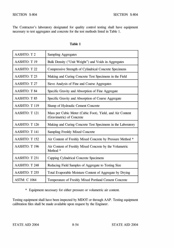
STATE AID 2004 STATE AID 2004
STATE AID 2004 STATE AID 20048-54
SECTION S-804 SECTION S-804
The Contractor’s laboratory designated for quality control testing shall have equipmentnecessary to test aggregates and concrete for the test methods listed in Table 1.
Table 1
AASHTO: T 2 Sampling Aggregates
AASHTO: T 19 Bulk Density (“Unit Weight”) and Voids in Aggregates
AASHTO: T 22 Compressive Strength of Cylindrical Concrete Specimens
AASHTO: T 23 Making and Curing Concrete Test Specimens in the Field
AASHTO: T 27 Sieve Analysis of Fine and Coarse Aggregates
AASHTO: T 84 Specific Gravity and Absorption of Fine Aggregate
AASHTO: T 85 Specific Gravity and Absorption of Coarse Aggregate
AASHTO: T 119 Slump of Hydraulic Cement Concrete
AASHTO: T 121 Mass per Cubic Meter (Cubic Foot), Yield, and Air Content(Gravimetric) of Concrete
AASHTO: T 126 Making and Curing Concrete Test Specimens in the Laboratory
AASHTO: T 141 Sampling Freshly Mixed Concrete
AASHTO: T 152 Air Content of Freshly Mixed Concrete by Pressure Method *
AASHTO: T 196 Air Content of Freshly Mixed Concrete by the VolumetricMethod *
AASHTO: T 231 Capping Cylindrical Concrete Specimens
AASHTO: T 248 Reducing Field Samples of Aggregate to Testing Size
AASHTO: T 255 Total Evaporable Moisture Content of Aggregate by Drying
ASTM: C 1064 Temperature of Freshly Mixed Portland Cement Concrete
* Equipment necessary for either pressure or volumetric air content.
Testing equipment shall have been inspected by MDOT or through AAP. Testing equipmentcalibration files shall be made available upon request by the Engineer.
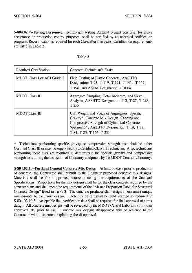
STATE AID 2004 STATE AID 2004
STATE AID 2004 STATE AID 20048-55
SECTION S-804 SECTION S-804
S-804.02.9--Testing Personnel. Technicians testing Portland cement concrete, for eitheracceptance or production control purposes, shall be certified by an accepted certificationprogram. Recertification is required for each Class after five years. Certification requirementsare listed in Table 2.
Table 2
Required Certification Concrete Technician’s Tasks
MDOT Class I or ACI Grade I Field Testing of Plastic Concrete, AASHTODesignation: T 23, T 119, T 121, T 141, T 152, T 196, and ASTM Designation: C 1064
MDOT Class II Aggregate Sampling, Total Moisture, and SieveAnalysis, AASHTO Designation: T 2, T 27, T 248,T 255
MDOT Class III Unit Weight and Voids of Aggregates, SpecificGravity*, Concrete Mix Design, Capping andCompressive Strength of Cylindrical ConcreteSpecimens*, AASHTO Designation: T 19, T 22, T 84, T 85, T 126, T 231
* Technicians performing specific gravity or compressive strength tests shall be eitherCertified Class III or may be supervised by a Certified Class III Technician. Also, techniciansperforming these tests are required to demonstrate the specific gravity and compressivestrength tests during the inspection of laboratory equipment by the MDOT Central Laboratory.
S-804.02.10--Portland Cement Concrete Mix Design. At least 30 days prior to productionof concrete, the Contractor shall submit to the Engineer proposed concrete mix designs.Materials shall be from approved sources meeting the requirements of the StandardSpecifications. Proportions for the mix designs shall be for the class concrete required by thecontract plans and shall meet the requirements of the “Master Proportion Table for StructuralConcrete Design” listed in Table 3. The concrete producer shall assign a permanent uniquemix number to each mix design. Each mix design shall be field verified as required inS-804.02.10.3. Acceptable field verification data shall be required for final approval of a mixdesign. All concrete mix designs will be reviewed by the MDOT Central Laboratory, or otherapproved lab, prior to use. Concrete mix designs disapproved will be returned to theContractor with a statement explaining the disapproval.

8-56
SECTION S-804 SECTION S-804
Table 3
MASTER PROPORTION TABLE FOR STRUCTURAL CONCRETE DESIGN
CLASS COARSEAGGREGATESIZE NO. *
MAXIMUM WATER/
CEMENTITIOUS RATIO **
SPECIFIEDCOMPRESSIVESTRENGTH (f’c)
MAXIMUM SLUMP ***
TOTALAIR
CONTENT
psi inches %
AA 57 or 67 0.45 4000 3 3.0 to 6.0
A 57 or 67 0.45 4000 3 3.0 to 6.0
BB 57 or 67 0.50 3500 4 3.0 to 6.0
B 57 or 67 0.50 3500 4 3.0 to 6.0
C 57 or 67 0.55 3000 4 3.0 to 6.0
D 57 or 67 0.70 2000 4 3.0 to 6.0
F 67 0.40 5000 3 ****
FX 67 (As required by special provisions) 3 ****
S 57 or 67 0.45 3000 8 3.0 to 6.0
DS 67 0.45 4000 ***** ****
* Maximum size aggregate shall conform to the concrete mix design for the specified aggregate.
** Maximum replacement of Portland cement by weight is 25% for fly ash or 50% for ground
granulated blast furnace slag. The addition of fly ash as a replacement for cement will not bepermitted in Type IP blended hydraulic cement, portland cement combined with groundgranulated blast furnace slag or Type III portland cement when specified in the contract.
*** The slump may be increased up to 6 inches with an approved mid-range water reducer or up to8 inches with an approved type F or G high range water reducer. A mid-range water reducer isclassified as a water reducer that reduces the mix water a minimum of 8% when compared toa control mix with no admixtures. Minus slump requirements shall meet those set forth in Table3 of AASHTO M157 specifications.
**** No entrained air except for pilings exposed to seawater.
***** Class DS Concrete for drilled shafts shall have an 8 ±1-inch slump. In the event the free fallmethod of concrete placement is used, the slump shall be 6 ±1-inch. No fly ash, groundgranulated blast furnace slag, or F or G high range water reducers allowed in drilled shaftconcrete. A slump retention admixture is required.
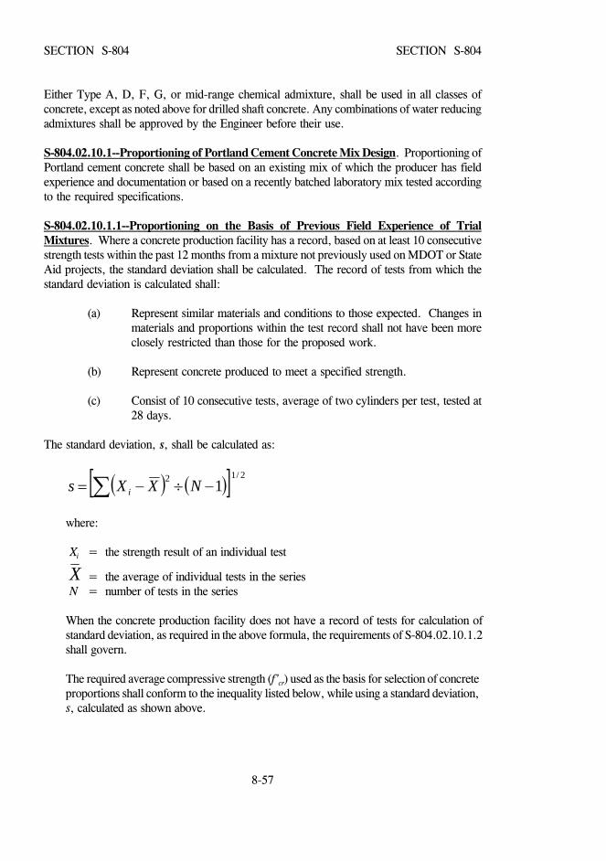
8-57
SECTION S-804 SECTION S-804
Either Type A, D, F, G, or mid-range chemical admixture, shall be used in all classes ofconcrete, except as noted above for drilled shaft concrete. Any combinations of water reducingadmixtures shall be approved by the Engineer before their use.
S-804.02.10.1--Proportioning of Portland Cement Concrete Mix Design. Proportioning ofPortland cement concrete shall be based on an existing mix of which the producer has fieldexperience and documentation or based on a recently batched laboratory mix tested accordingto the required specifications.
S-804.02.10.1.1--Proportioning on the Basis of Previous Field Experience of TrialMixtures. Where a concrete production facility has a record, based on at least 10 consecutivestrength tests within the past 12 months from a mixture not previously used on MDOT or StateAid projects, the standard deviation shall be calculated. The record of tests from which thestandard deviation is calculated shall:
(a) Represent similar materials and conditions to those expected. Changes inmaterials and proportions within the test record shall not have been moreclosely restricted than those for the proposed work.
(b) Represent concrete produced to meet a specified strength.
(c) Consist of 10 consecutive tests, average of two cylinders per test, tested at28 days.
The standard deviation, s, shall be calculated as:
( ) ( )[ ] 2/12 1∑ −÷−= NXXs i
where:
Xi = the strength result of an individual test
= the average of individual tests in the series X N = number of tests in the series
When the concrete production facility does not have a record of tests for calculation ofstandard deviation, as required in the above formula, the requirements of S-804.02.10.1.2shall govern.
The required average compressive strength (f’cr) used as the basis for selection of concreteproportions shall conform to the inequality listed below, while using a standard deviation,s, calculated as shown above.
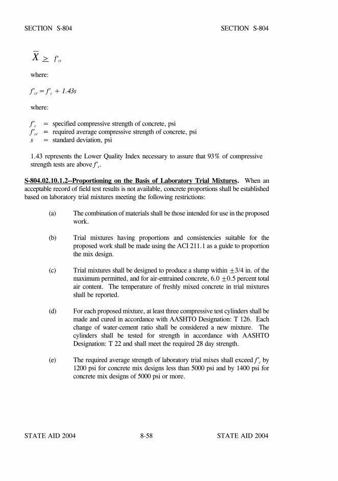
STATE AID 2004 STATE AID 2004
STATE AID 2004 STATE AID 20048-58
SECTION S-804 SECTION S-804
> f’crXwhere:
f’cr = f’c + 1.43s
where:
f’c = specified compressive strength of concrete, psif’cr = required average compressive strength of concrete, psis = standard deviation, psi
1.43 represents the Lower Quality Index necessary to assure that 93% of compressivestrength tests are above f’c.
S-804.02.10.1.2--Proportioning on the Basis of Laboratory Trial Mixtures. When anacceptable record of field test results is not available, concrete proportions shall be establishedbased on laboratory trial mixtures meeting the following restrictions:
(a) The combination of materials shall be those intended for use in the proposedwork.
(b) Trial mixtures having proportions and consistencies suitable for theproposed work shall be made using the ACI 211.1 as a guide to proportionthe mix design.
(c) Trial mixtures shall be designed to produce a slump within ±3/4 in. of themaximum permitted, and for air-entrained concrete, 6.0 ±0.5 percent totalair content. The temperature of freshly mixed concrete in trial mixturesshall be reported.
(d) For each proposed mixture, at least three compressive test cylinders shall bemade and cured in accordance with AASHTO Designation: T 126. Eachchange of water-cement ratio shall be considered a new mixture. Thecylinders shall be tested for strength in accordance with AASHTODesignation: T 22 and shall meet the required 28 day strength.
(e) The required average strength of laboratory trial mixes shall exceed f’c by1200 psi for concrete mix designs less than 5000 psi and by 1400 psi forconcrete mix designs of 5000 psi or more.
8-59
SECTION S-804 SECTION S-804
(f) The laboratory trial batch mixtures shall have been made within theprevious 12 months before being submitted for approval and shall not havebeen previously used on MDOT or State Aid projects.
S-804.02.10.2--Documentation of Average Strength. Documentation that the proposedconcrete proportions will produce an average strength equal to or greater than the requiredaverage shall consist of the strength test records from field tests or results from laboratory trialmixtures.
S-804.02.10.3--Field Verification of Concrete Mix Design. Concrete mix designs will onlybe tentatively approved pending field verification. Mix designs may be transferred to otherprojects without additional field verification testing, once the mix design has passed the fieldverification process.
The Contractor’s Certified Quality Control Technicians shall test each concrete mix designupon the first placement of the mix. Aggregates and concrete tests during the first placementshall be as follows:
Aggregates ConcreteBulk Specific Gravity Water ContentMoisture SlumpGradation Air Content
Unit WeightYield
The mix shall be verified to yield within 2.0% of the correct volume when all the mix wateris added to the batch, producing a slump within a minus 1½ inches tolerance, or minus 2½inches with Type F or G chemical admixture, of the maximum permitted and total air contentwithin a minus 1½ percent tolerance of the maximum allowable air content listed in Table 3.The mix shall be adjusted and retested, if necessary, on subsequent placements until the abovementioned properties are met. If the requirements of yield, slump, or air are not met after threeattempts, subsequent field verification testing shall not be permitted, and the mix design shallnot be used until the requirements listed above are met. Any mix design adjustments, changesin the mix proportions, are to be made by a Class III Certified Technician representing theContractor. After the mix design has been verified and adjustments made, verification testresults will be reviewed by the Engineer.
STATE AID 2004 STATE AID 2004
STATE AID 2004 STATE AID 20048-60
SECTION S-804 SECTION S-804
S-804.02.10.4--Adjustments of Mixtures Proportions. After ten compressive tests havebeen performed for which a standard deviation is calculated, the mix design may be adjusted
provided the average strength ( ) complies with the inequality in S-804.02.10.1.1 and theXadjusted mix design satisfies the water/cementitious ratio requirement listed in Table 3. Anyadjustments of the concrete mix design shall necessitate repeat of field verification procedureas described in S-804.02.10.3 and approval by the Engineer.
S-804.02.11--Concrete Batch Plants. The concrete batch plant and assigned mixer trucksshall be on the list of approved concrete batch plants and mixer trucks. For large quantityprojects the plant shall meet the requirements for an automatic system capable of recordingbatch weights. It shall also have automatically moisture compensation for the fine aggregate.
For projects, with the total volume less than two thousand(2000) cubic yards, the plant can beequipped for manual batching with a fine aggregate moisture meter visible to the plantoperator.
The concrete batch plant shall have available adequate facilities to cool concrete during hotweather.
S-804.02.12--Contractor’s Quality Control. The Contractor shall provide and maintain aquality control program that will provide reasonable assurance that all materials and productssubmitted to the Engineer for acceptance will conform to the contract requirements, whethermanufactured or processed by the Contractor or procured from suppliers, subcontractors, orvendors.
The Contractor's Quality Control program shall implement the minimum quality controlrequirements shown in Table 4, "Contractor’s MINIMUM REQUIREMENTS FORQUALITY CONTROL”. The quality control activities shown in the table are considered tobe normal activities necessary to control the production and placing of a given product ormaterial at an acceptable quality level. To facilitate the Engineer’s activities, all completedgradation samples shall be retained for a minimum of sixty (60) days by the Contractor or untilfurther disposition is designated by the Engineer.
The Contractor shall perform, or have performed, the inspections and tests required tosubstantiate product conformance to contract document requirements and shall also perform,or have performed, all inspections and tests otherwise required.
The Contractor’s Quality Control program shall encompass the requirements of AASHTODesignation: M 157 into concrete production and control, equipment requirements, testing, andbatch ticket information. The requirement of AASHTO Designation: M 157, Section 11.7shall be followed except, on arrival to the job site, a maximum of 1½ gallons of water percubic yard shall be allowed to be added to bring the slump within the required limits. Watershall not be added at a later time.
STATE AID 2004 STATE AID 2004
STATE AID 2004 STATE AID 20048-61
SECTION S-804 SECTION S-804
The Contractor's quality control inspections and tests shall be documented and shall beavailable for review by the Engineer throughout the life of the contract.
As set out in these specifications, quality control sampling and testing performed by theContractor will be used by the Engineer for determination of acceptability of the concrete.
The Contractor shall maintain standard equipment and qualified personnel as required to assureconformance to contract requirements.
S-804.02.12.1--Quality Control Plan. The Contractor shall prepare a Quality Control Planwhich shall identify the personnel responsible for the Contractor’s quality control including thecompany official who will act as liaison with the Engineer. The Quality Control Plan shall besubmitted in writing to the Engineer for approval 30 days prior to the production of concrete.
The class(es) of concrete involved will be listed separately. If an existing mix design(s) is tobe used, the mix design number(s) as previously approved shall be listed.
It is intended that sampling and testing be in accordance with standard methods and procedures,and that measuring and testing equipment be standard and properly calibrated. If alternativesampling methods and procedures, and inspection equipment are to be used, they shall bedetailed in the Quality Control Plan.
S-804.02.12.1.1--Elements of Plan. The Plan shall address all elements that affect the qualityof the structural concrete including, but not limited to, the following:
(a) Stockpile Management(b) Procedures for Corrective Actions for Noncompliance of Specifications (c) Procedure for Controlling Concrete Temperatures
S-804.02.12.2--Personnel Requirements. The Contractor’s Designated Certified Technicianshall perform and use quality control tests and other quality control practices to assure thatdelivered materials and proportioning meet the requirements of the mix design includingtemperature, slump, air content, and strength and shall periodically inspect all equipment usedin transporting, proportioning, and mixing.
The Contractor’s Designated Technician shall periodically inspect all equipment used placing,consolidating, finishing, and curing to assure it is operating properly and that placement,consolidation, finishing, and curing conform to the mix design and other contract requirements.
STATE AID 2004 STATE AID 2004
STATE AID 2004 STATE AID 20048-62
SECTION S-804 SECTION S-804
S-804.02.12.3--Documentation. The Contractor shall maintain adequate records of allinspections and tests. The records shall indicate the nature and number of observations made,the number and type of deficiencies found, date and time of samples taken, the quantitiesapproved and rejected, and the nature of corrective action taken as appropriate. TheContractor's documentation procedures will be subject to approval of the Engineer prior to thestart of the work and to compliance checks during the progress of the work.
All conforming and nonconforming inspections and test results shall be kept complete and shallbe available at all times to the Engineer during the performance of the work. Forms shall beon a computer-acceptable medium. Batch tickets and gradation data shall be documented inaccordance with State Aid requirements. Copies shall be submitted to the Engineer as the workprogresses.
Test data for Portland cement concrete, including gradation, shall be charted in accordance withthe applicable requirements.
The Contractor may use additional control charts as deemed appropriate. It is normallyexpected that testing and charting will be completed within 24 hours after sampling.
All charts and records documenting the Contractor's quality control inspections and tests shallbecome the property of the Engineer upon completion of the work.
S-804.02.12.4--Corrective Action. The Contractor shall take prompt action to correctconditions that have resulted, or could result, in the delivery to the Project of materials andproducts that do not conform to the requirements of the contract documents. All correctiveactions shall be documented.
S-804.02.12.5--Non-Conforming Materials. The Contractor shall establish and maintain aneffective and positive system for controlling non-conforming material, including procedures forits identification, isolation and disposition. Reclaiming or reworking of non-conformingmaterials shall be in accordance with procedures acceptable to the Engineer.
All non-conforming materials and products shall be positively identified to prevent use,shipment, and intermingling with conforming materials and products. Holding areas, mutuallyagreeable to the Engineer and the Contractor, shall be provided by the Contractor.
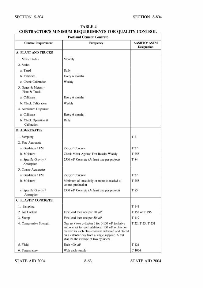
STATE AID 2004 STATE AID 2004
STATE AID 2004 STATE AID 20048-63
SECTION S-804 SECTION S-804
TABLE 4CONTRACTOR’S MINIMUM REQUIREMENTS FOR QUALITY CONTROL
Portland Cement Concrete
Control Requirement Frequency AASHTO/ ASTMDesignation
A. PLANT AND TRUCKS
1. Mixer Blades Monthly
2. Scales
a. Tared Daily
b. Calibrate Every 6 months
c. Check Calibration Weekly
3. Gages & Meters - Plant & Truck
a. Calibrate Every 6 months
b. Check Calibration Weekly
4. Admixture Dispenser
a. Calibrate Every 6 months
b. Check Operation & Calibration
Daily
B. AGGREGATES
1. Sampling T 2
2. Fine Aggregate
a. Gradation / FM 250 yd³ Concrete T 27
b. Moisture Check Meter Against Test Results Weekly T 255
c. Specific Gravity / Absorption
2500 yd³ Concrete (At least one per project) T 84
3. Coarse Aggregates
a. Gradation / FM 250 yd³ Concrete T 27
b. Moisture Minimum of once daily or more as needed tocontrol production
T 255
c. Specific Gravity / Absorption
2500 yd³ Concrete (At least one per project) T 85
C. PLASTIC CONCRETE
1. Sampling T 141
2. Air Content First load then one per 50 yd³ T 152 or T 196
3. Slump First load then one per 50 yd³ T 119
4. Compressive Strength One set ( two cylinders ) for 0-100 yd³ inclusiveand one set for each additional 100 yd³ or fractionthereof for each class concrete delivered and placedon a calendar day from a single supplier. A testshall be the average of two cylinders.
T 22, T 23, T 231
5. Yield Each 400 yd³ T 121
6. Temperature With each sample C 1064

STATE AID 2004 STATE AID 2004
STATE AID 2004 STATE AID 20048-64
SECTION S-804 SECTION S-804
S-804.02.13--Quality Assurance Sampling and Testing. Quality Assurance (QA) inspectionand testing will be provided by the Engineer to assure that the Contractor’s Quality Control(QC) testing meets the requirements of these specifications.
Acceptance of the material is based on the inspection of the construction, monitoring of theContractor's quality control program, QC test results, and the comparison of the QA testresults with the QC test results. The Engineer may use the results of the Contractor’s QC testsas a part of the acceptance procedures instead of the results of QA tests, provided:
(a) The Engineer's inspection and monitoring activities indicate that theContractor is following the approved Quality Control program and,respectively,
(b) For aggregates, the results from the Contractor's QC and the Engineer’sQA testing of aggregate gradations compare by both meeting the aggregatetype’s gradation requirements;
(c) For concrete, the Contractor's QC and Engineer’s QA testing of concretecompressive strengths compare within 990 psi provided both the QC andQA test results are equal to or exceed the minimum compressive strengthrequirements.
The minimum frequency for QA testing of aggregate and plastic concrete by the Engineer willfollow the frequencies listed in Table 5, “ MINIMUM REQUIREMENTS FOR QUALITYASSURANCE”.
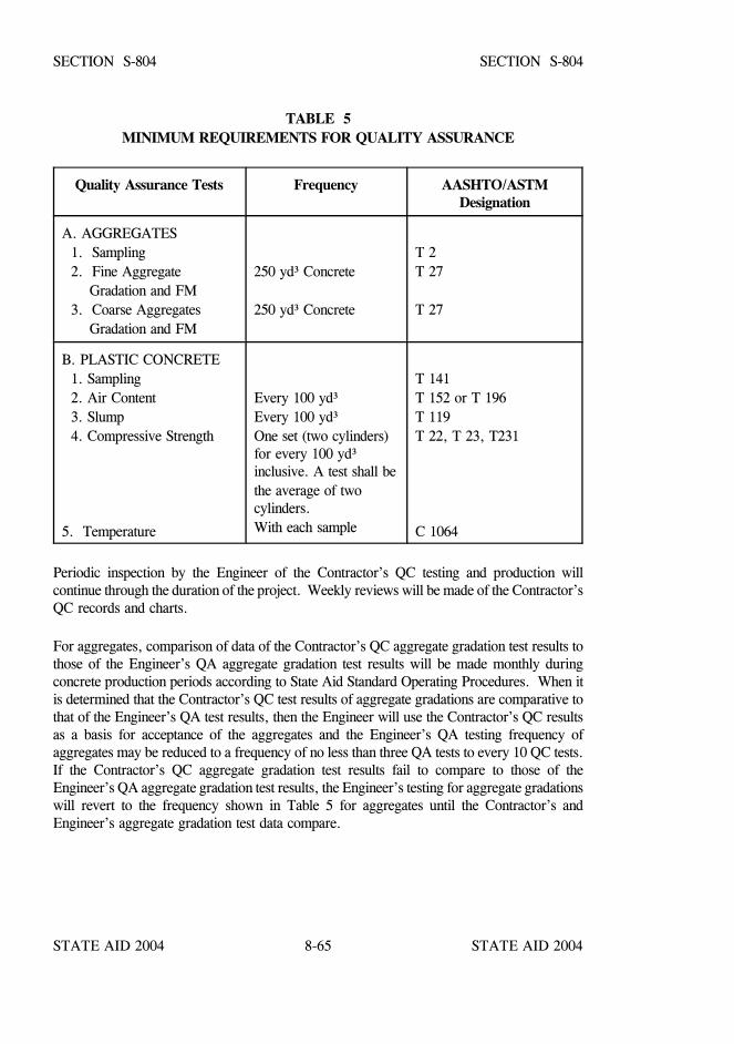
STATE AID 2004 STATE AID 2004
STATE AID 2004 STATE AID 20048-65
SECTION S-804 SECTION S-804
TABLE 5MINIMUM REQUIREMENTS FOR QUALITY ASSURANCE
Quality Assurance Tests Frequency AASHTO/ASTMDesignation
A. AGGREGATES 1. Sampling 2. Fine Aggregate Gradation and FM 3. Coarse Aggregates Gradation and FM
250 yd³ Concrete
250 yd³ Concrete
T 2T 27
T 27
B. PLASTIC CONCRETE 1. Sampling 2. Air Content 3. Slump 4. Compressive Strength
5. Temperature
Every 100 yd³Every 100 yd³One set (two cylinders)for every 100 yd³inclusive. A test shall bethe average of twocylinders.With each sample
T 141T 152 or T 196T 119T 22, T 23, T231
C 1064
Periodic inspection by the Engineer of the Contractor’s QC testing and production willcontinue through the duration of the project. Weekly reviews will be made of the Contractor’sQC records and charts.
For aggregates, comparison of data of the Contractor’s QC aggregate gradation test results tothose of the Engineer’s QA aggregate gradation test results will be made monthly duringconcrete production periods according to State Aid Standard Operating Procedures. When itis determined that the Contractor’s QC test results of aggregate gradations are comparative tothat of the Engineer’s QA test results, then the Engineer will use the Contractor’s QC resultsas a basis for acceptance of the aggregates and the Engineer’s QA testing frequency ofaggregates may be reduced to a frequency of no less than three QA tests to every 10 QC tests.If the Contractor’s QC aggregate gradation test results fail to compare to those of theEngineer’s QA aggregate gradation test results, the Engineer’s testing for aggregate gradationswill revert to the frequency shown in Table 5 for aggregates until the Contractor’s andEngineer’s aggregate gradation test data compare.
STATE AID 2004 STATE AID 2004
STATE AID 2004 STATE AID 20048-66
SECTION S-804 SECTION S-804
For concrete compressive strength, comparison of data of the Contractor’s QC compressivestrength test results to those of the Engineer’s QA compressive strength test results will bemade monthly during concrete production periods according to State Aid Standard OperatingProcedures. When it is determined that the Contractor’s QC test results of concretecompressive strengths are comparative to that of the Engineer’s QA test results, then theEngineer will use the Contractor’s QC results as a basis for acceptance of the concrete and theEngineer’s QA testing frequency of concrete compressive strengths may be reduced to afrequency of no less than three QA tests to every 10 QC tests. If the Contractor’s QCcompressive strength test results fail to compare to those of the Engineer’s QA compressivestrength test results, the Engineer’s testing will revert to the frequency shown in Table 5 forplastic concrete until the Contractor’s and Engineer’s compressive strength test data compare.
S-804.02.13.1--Basis of Acceptance.
S-804.02.13.1.1--Slump. Slump of plastic concrete shall meet the requirements of Table 3:MASTER PROPORTION TABLE FOR STRUCTURAL CONCRETE DESIGN. A checktest shall be made on another portion of the sample before rejection of any load.
S-804.02.13.1.2--Air. Total air content of concrete shall be within the specified range for theclass of concrete listed in Table 3: MASTER PROPORTION TABLE FOR STRUCTURALCONCRETE DESIGN. A check test shall be made on another portion of the sample beforerejection of any load.
S-804.02.13.1.3--Yield. If the yield of the concrete mix design is more than plus or minus 3%of the designed volume, the mix shall be adjusted by a Class III Certified Technicianrepresenting the Contractor to yield the correct volume plus or minus three percent (±3%).If batching of the proportions of the mix design varies outside the batching tolerance range ofthe originally approved proportions by more than the tolerances allowed in S-804.02.13.1, thenew proportions shall be field verified per S-804.02.10.3.
S-804.02.13.1.4--Temperature. Cold weather concreting shall follow the requirements ofS-804.03.16.1. Hot weather concreting shall follow the requirements of S-804.03.16.2 witha maximum concrete temperature of 95oF for Class DS concrete containing a slump retentionadmixture and for concrete mixes containing pozzolanic materials as a replacement of Portlandcement. For other classes of concrete without pozzolanic materials, the maximum concretetemperature shall be 90oF. Concrete with a temperature more than the maximum allowabletemperature shall be rejected and not used in State Aid work.
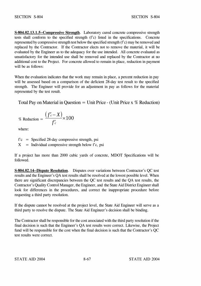
STATE AID 2004 STATE AID 2004
STATE AID 2004 STATE AID 20048-67
SECTION S-804 SECTION S-804
S-804.02.13.1.5--Compressive Strength. Laboratory cured concrete compressive strengthtests shall conform to the specified strength (f’c) listed in the specifications. Concreterepresented by compressive strength test below the specified strength (f’c) may be removed andreplaced by the Contractor. If the Contractor elects not to remove the material, it will beevaluated by the Engineer as to the adequacy for the use intended. All concrete evaluated asunsatisfactory for the intended use shall be removed and replaced by the Contractor at noadditional cost to the Project. For concrete allowed to remain in place, reduction in paymentwill be as follows:
When the evaluation indicates that the work may remain in place, a percent reduction in paywill be assessed based on a comparison of the deficient 28-day test result to the specifiedstrength. The Engineer will provide for an adjustment in pay as follows for the materialrepresented by the test result.
Total Pay on Material in Question = Unit Price - (Unit Price x % Reduction)
% Reduction = ( ) 100×
′−′
c
c
fXf
where:
f’c = Specified 28-day compressive strength, psi X = Individual compressive strength below f’c, psi
If a project has more than 2000 cubic yards of concrete, MDOT Specifications will befollowed.
S-804.02.14--Dispute Resolution. Disputes over variations between Contractor’s QC testresults and the Engineer’s QA test results shall be resolved at the lowest possible level. Whenthere are significant discrepancies between the QC test results and the QA test results, theContractor’s Quality Control Manager, the Engineer, and the State Aid District Engineer shalllook for differences in the procedures, and correct the inappropriate procedure beforerequesting a third party resolution.
If the dispute cannot be resolved at the project level, the State Aid Engineer will serve as athird party to resolve the dispute. The State Aid Engineer’s decision shall be binding.
The Contractor shall be responsible for the cost associated with the third party resolution if thefinal decision is such that the Engineer’s QA test results were correct. Likewise, the Projectfund will be responsible for the cost when the final decision is such that the Contractor’s QCtest results were correct.
STATE AID 2004 STATE AID 2004
STATE AID 2004 STATE AID 20048-68
SECTION S-804 SECTION S-804
S-804.03--Construction Requirements.
S-804.03.1--Measurement of Materials.
S-804.03.1.1--General. The accuracy for measuring materials shall be in accordance withAASHTO Designation: M 157.
S-804.03.1.2--Measurement by Weighing. Except when otherwise specified or authorized,materials shall be measured by weighing. The apparatus provided for weighing materials shallbe suitably designed and constructed for this purpose. Cement and aggregates shall beweighed separately. Cement in standard bags need not be weighed, but bulk cement shall beweighed. The mixing water shall be measured by volume or by weight. All measuringdevices shall be subject to approval.
S-804.03.2--Blank.
S-804.03.3--Blank.
S-804.03.4--Hand Mixing. Hand mixing of concrete will not be allowed.
S-804.03.5--Delivery. The plant supplying concrete shall have sufficient capacity andtransporting apparatus to insure continuous delivery at the rate required. The rate of deliveryshall be such as to provide for the proper continuity in handling, placing, and furnishing of theconcrete. The rate shall be such that the interval between batches shall not exceed 20 minutes.The methods of delivering and handling the concrete shall be that which will facilitate placingwith minimum rehandling and without damage to the structure or the concrete.
S-804.03.6--Handling and Placing Concrete.
S-804.03.6.1--General. Prior to placing concrete, all reinforcement shall have been accuratelyplaced in the position shown on the plans and fastened as set out in S-805. All sawdust, chips,and other construction debris and extraneous matter shall have been removed from the interiorof the forms. Temporary struts, braces, and stays holding the forms in correct shape andalignment shall be removed when the concrete placing has reached an elevation rendering theirservice unnecessary. These temporary members shall be entirely removed from the forms andshall not be buried in the concrete.
No concrete shall be placed until the forms and reinforcement have been inspected.
Except as provided for truck mixers and truck agitators, concrete shall be placed in the formswithin 30 minutes after the time that the cement is first added to the mix.
STATE AID 2004 STATE AID 2004
STATE AID 2004 STATE AID 20048-69
SECTION S-804 SECTION S-804
Concrete shall be placed so as to avoid segregation of materials and displacement ofreinforcement. The use of troughs, chutes, and pipes over 25 feet in length for gravityconveyance of concrete to the forms, will not be permitted except when authorized by theEngineer and subject to the production of quality concrete.
Only approved mechanical conveyors will be permitted.
Open troughs and chutes shall be metal or metal lined. The use of aluminum pipes, chutes,or other devices made of aluminum that come into direct contact with the concrete shall not beused. Where steep slopes are required, the chutes shall be equipped with baffles or be in shortsections that change the direction of movement.
All chutes, troughs, and pipes shall be kept clean and free from coatings of hardened concreteby thoroughly flushing with water after each run. Water used for flushing shall be dischargedclear of the structure.
When placing operations involve dropping the concrete more than five feet, it shall bedeposited through sheet metal or other approved pipes to prevent segregation and unnecessarysplashing. The pipes shall be made in sections to permit discharging and raising as theplacement progresses. A non-jointed pipe may be used if sufficient openings of the proper sizeare provided to allow for the flow of the concrete into the shaft. As far as practicable, thepipes shall be kept full of concrete during placing, and their ends shall be kept buried in thenewly placed concrete.
Except as hereinafter provided, concrete shall be placed in horizontal layers not more than 12inches thick. When, with the Engineer's approval, less than the complete length of a layer isplaced in one operation, it shall be terminated in a vertical bulkhead. Each layer shall beplaced and compacted before the preceding layer has taken its initial set and shall be compactedso as to avoid the formation of a construction joint with the preceding layer.
S-804.03.6.2--Consolidation. Concrete, during and immediately after depositing, shall bethoroughly consolidated by the use of approved mechanical vibrators and suitable spadingtools. Hand spading alone will be permitted on small structural members such as railing andsmall culvert headwalls. Mechanical vibration of concrete shall be subject to the following:
STATE AID 2004 STATE AID 2004
STATE AID 2004 STATE AID 20048-70
SECTION S-804 SECTION S-804
A. The vibration shall be internal unless special authorization of other methodsis given by the Engineer or as provided herein.
B. In general, vibrators shall be a type and design approved by the Engineer.They shall be capable of vibration frequencies of at least 4500 impulses perminute.
C. The intensity of vibration shall be such as to visibly affect a mass ofconcrete of one inch slump over a radius of at least 18 inches.
D. The Contractor shall provide sufficient vibrators to properly compact eachbatch immediately after it is placed in the forms.
E. Vibrators shall be manipulated so as to thoroughly work the concretearound the reinforcement and embedded fixtures and into the corners andangles of the forms.
Vibration shall be applied at the point of deposit and in the area of freshlydeposited concrete. The vibrators shall be inserted into and withdrawn outof the concrete slowly. The vibration shall be of sufficient duration andintensity to thoroughly compact the concrete, but shall not be continued soas to cause segregation. Vibration shall not be continued at any one pointto the extent that localized areas of grout are formed.
Application of vibrators shall be at points uniformly spaced and not fartherapart than twice the radius over which the vibration is visibly effective.
F. Vibration shall not be applied directly or through the reinforcement tosections or layers of concrete which have taken initial set. It shall not beused to make concrete flow in the forms over distances so great as to causesegregation, and vibrators shall not be used to transport concrete in theforms.
G. Vibration shall be supplemented by spading as necessary to insure smoothsurfaces and dense concrete along form surfaces, in corners, and inlocations impossible to reach with vibrators.
H. These provisions shall apply to the filler concrete for steel grid floors exceptthat the vibrator shall be applied to the steel.
I. These provisions shall apply to precast piling, concrete cribbing, and otherprecast members except that, if approved by the Engineer, themanufacturer's methods of vibrations may be used.
STATE AID 2004 STATE AID 2004
STATE AID 2004 STATE AID 20048-71
SECTION S-804 SECTION S-804
When hand spading is used for consolidation, a sufficient number of workmen with spadingtools shall be provided. They will be required to flush a thin layer of mortar to all the surfacesand thoroughly and satisfactorily consolidate the concrete.
The entire operation of depositing and consolidating the concrete shall be conducted so that theconcrete shall be smooth and dense and free from honeycomb or pockets of segregatedaggregate.
S-804.03.6.3--Discontinuance of Placing. When placing is temporarily discontinued, theconcrete, after becoming firm enough to retain its form, shall be cleaned of laitance and otherobjectionable material to a sufficient depth to expose sound concrete. To avoid visible jointsinsofar as possible upon exposed faces, the top surface of the concrete adjacent to the formsshall be smoothed with a trowel. Where a "feather edge" might be produced at a constructionjoint, such as in the sloped top surface of a wing wall, an inset form work shall be used in thepreceding layer to produce a blocked out portion that will provide an edge thickness of at leastsix inches in the succeeding layer. Work shall not be discontinued within 18 inches of the topof any face unless provision has been made for a coping less than 18 inches thick. In this caseand if permitted by the Engineer, the construction joint may be made at the under side of thecoping.
Immediately following the discontinuance of placing concrete, all accumulations of mortarsplashed on the reinforcement and the surface of forms shall be removed. Dried mortar chipsand dust shall not be puddled into the unset concrete. If the accumulations are not removedprior to the concrete becoming set, care shall be exercised not to break or injure theconcrete-steel bond at and near the surface of the concrete while cleaning the reinforcement.After initial set the forms shall not be jarred, and no strain shall be placed on the ends ofprojecting reinforcement until the concrete has sufficiently set to insure against any damage bysuch jarring or strain.
S-804.03.6.4--Placing Bridge Concrete. The method and sequence of placing concrete shallconform to the provisions and requirements set forth for the particular type of construction.
S-804.03.6.4.1--Foundations and Substructures. Concrete seals shall be placed inaccordance with S-804.03.9. All other concrete for foundations shall be poured in the dryunless otherwise stipulated or authorization is given in writing by the Engineer to do otherwise.Concrete shall not be placed in foundations until the foundation area has been inspected andapproved.
Unless otherwise specified, the placement of concrete in the substructure shall be in accordancewith the general requirements of S-804.03.6.
Unless otherwise directed, concrete in columns shall be placed in one continuous operation,and shall be allowed to set at least 12 hours before the caps are placed.
STATE AID 2004 STATE AID 2004
STATE AID 2004 STATE AID 20048-72
SECTION S-804 SECTION S-804
S-804.03.6.4.2--Superstructure. For simple spans, concrete shall preferably be deposited bybeginning at the center of the span and working toward the ends. For continuous spans,concrete shall be deposited as shown on the plans. Concrete in girders shall be uniformlydeposited for the full length of the girder and brought up evenly in horizontal layers.
Unless otherwise permitted by the Engineer, concrete shall not be placed in the superstructureuntil the column forms have been stripped sufficiently to determine the character of theconcrete in the columns. Unless otherwise permitted by the Engineer, the load of thesuperstructure shall not be placed on pile bents until the caps have been in place at least 7 daysand shall not be placed on other types of bents until the bents have been in place at least 14days.
In placing concrete around steel shapes, it shall be placed on one side of the shape until itflushes up over the bottom flange of the shape on the opposite side, after which it shall beplaced on both sides to completion.
Concrete in girder haunches less than three feet in height shall be placed at the same time asthat in the girder stem. Whenever a haunch or fillet has a height of three feet or more at theabutment or columns, the haunch and the girder shall be poured in three successive stages:first, up to the lower side of the haunch; second, to the lower side of the girder; and third, tocompletion.
Except when intermediate construction joints are specified, concrete in slab, T-beam, ordeck-girder spans shall be placed in one continuous operation for each span.
The floors and girders of through-girder superstructures shall be placed in one continuousoperation unless otherwise specified, in which case special shear anchorage shall be providedto insure monolithic action between girder and floor.
Concrete in box girders shall be placed as shown on the plans.
Concrete shall not be chuted directly into the forms of the span and shall be placedcontinuously with sufficient speed to be monolithic and to allow for finishing before initial set.
S-804.03.7--Pneumatic Placing. Pneumatic placing of concrete will be permitted only ifspecified in the contract or if authorized by the Engineer. The equipment shall be so arrangedthat no vibrations result which might damage freshly placed concrete.
STATE AID 2004 STATE AID 2004
STATE AID 2004 STATE AID 20048-73
SECTION S-804 SECTION S-804
Where concrete is conveyed and placed by pneumatic means the equipment shall be suitablein kind and adequate in capacity for the work. The machine shall be located as close aspracticable to the place of deposit. The position of the discharge end of the line shall not bemore than 10 feet from the point of deposit. The discharge lines shall be horizontal or inclinedupwards from the machine. At the conclusion of placement the entire equipment shall bethoroughly cleaned.
S-804.03.8--Pumping Concrete. Placement of concrete by pumping will be permitted onlyif specified in the contract or if authorized in writing by the Engineer. If used, the equipmentshall be arranged so that no vibrations result which might damage freshly placed concrete.
Where concrete is conveyed and placed by mechanically applied pressure, the equipment shallbe suitable in kind and adequate in capacity for the work. The operation of the pump shall besuch that a continuous stream of concrete without air pockets is produced. When pumping iscompleted, the concrete remaining in the pipe line, if it is to be used, shall be ejected in sucha manner that there will be no contamination of the concrete or separation of the ingredients.After this operation, the entire equipment shall be thoroughly cleaned.
The use of aluminum pipe as a conveyance for the concrete will not be permitted.
S-804.03.9--Depositing Concrete Under Water. Concrete shall not be deposited in waterexcept with the approval of the Engineer.
Concrete deposited under water shall be Class S.
Concrete deposited under water shall be carefully placed in a compact mass in its final positionby means of a tremie, a bottom dump bucket, or other approved method and shall not bedisturbed after being deposited. Special care shall be exercised to maintain still water at thepoint of deposit. No concrete shall be placed in running water and all form work designed toretain concrete under water shall be water-tight. The consistency of the concrete shall becarefully regulated, and special care shall be exercised to prevent segregation of materials.
Concrete seals shall be placed continuously from start to finish, and the surface of the concreteshall be kept as nearly horizontal as practicable at all times. To insure thorough bonding, eachsucceeding layer of a seal shall be placed before the preceding layer has taken initial set.
STATE AID 2004 STATE AID 2004
STATE AID 2004 STATE AID 20048-74
SECTION S-804 SECTION S-804
When a tremie is used, it shall consist of a tube having a diameter of at least 10 inches andconstructed in sections having flanged couplings fitted with gaskets. The means of supportingthe tremie shall be such as to permit the free movement of the discharge over the entire topsurface of the work and to permit it to be lowered rapidly when necessary to choke off orretard the flow of concrete. The discharge end shall be closed at the start of the work so as toprevent water entering the tube and shall be entirely sealed. The tremie tube shall be kept fullto the bottom of the hopper. When a batch is dumped into the hopper, the flow of concreteshall be induced by slightly raising the discharge end, always keeping it in the depositedconcrete. The flow is then stopped by lowering the tremie. The flow shall be continuous untilthe work is completed.
Depositing of concrete by the drop bottom bucket method shall conform to the following: Thetop of the bucket shall be open. The bottom doors shall open freely downward and outwardwhen tripped. The bucket shall be completely filled and slowly lowered to avoid backwash.It shall not be dumped until it rests on the surface upon which the concrete is to be depositedand when discharged shall be withdrawn slowly until well above the concrete.
Dewatering may proceed when the concrete seal is sufficiently hard and strong. As a generalrule, this time will be 48 hours for concrete made with high-early-strength cement and threedays for concrete made with other types of cement. All laitance and other unsatisfactorymaterial shall be removed from the exposed surface by scraping, chipping, or other meanswhich will not injure the surface of the concrete.
S-804.03.10--Construction Joints.
S-804.03.10.1--General. Unless otherwise approved by the Engineer, construction joints shallbe made only where located on the plans or shown in the pouring schedule. If not detailed onthe plans, or in the case of emergency, construction joints shall be placed as directed by theEngineer. Shear keys or inclined reinforcement shall be used where necessary to transmitshear or to bond the two sections together.
For continuous spans, bridge deck concrete shall be deposited as shown on the plans.Deviation from the pouring schedule shown in the plans is not permitted.
S-804.03.10.2--Bonding. Before depositing new concrete on or against concrete which hashardened, the forms shall be retightened. The surface of the hardened concrete shall beroughened as required by the Engineer and in a manner that will not leave loosened particlesof aggregate or damaged concrete at the surface. It shall be thoroughly cleaned of foreignmatter and laitance and saturated with water. When directed by the Engineer, the cleaned andsaturated surfaces, including vertical and inclined surfaces, shall first be thoroughly coveredwith a coating of mortar or neat cement grout against which the new concrete shall be placedbefore the grout has attained its initial set.
STATE AID 2004 STATE AID 2004
STATE AID 2004 STATE AID 20048-75
SECTION S-804 SECTION S-804
The placing of concrete shall be carried continuously from joint to joint. The face edges of alljoints which are exposed to view shall be carefully finished, true to line and elevation.
In order to bond successive courses suitable depressed or raised keys of the designated sizeshall be constructed. Raised keys shall be monolithic with the concrete of the lower course.
S-804.03.11--Concrete Exposed to Seawater. Unless otherwise specifically provided,concrete for structures exposed to seawater shall be Class AA concrete as referenced inS-804.02.10. The clear distance from the face of the concrete to the nearest face of reinforcingsteel shall be at least four inches. The mixing time and the water content shall be carefullycontrolled and regulated so as to produce concrete of maximum impermeability. The concreteshall be thoroughly compacted, and stone pockets shall be avoided. No construction jointsshall be formed between the levels of extreme low water and extreme high water as determinedby the Engineer. Between these levels, seawater shall not come in direct contact with the newconcrete until at least 30 days have elapsed. The surface concrete as left by the forms shall beleft undisturbed.
S-804.03.12--Blank.
S-804.03.13--Falsework. The Contractor shall submit to the Engineer two copies of structuraldesign analysis and detail drawings, which show the method of falsework or centering. Thesedesigns and detail plans shall be prepared and bear the seal of a Registered ProfessionalEngineer with experience in falsework design.
Falsework plans shall include falsework elevations together with all other dimensions anddetails which is considered necessary for the construction.
Other pertinent data needed is size and spacing of all falsework members and minimumbearing requirements for false piles.
Upon completion of falsework erection, the Registered Professional Engineer shall certify thatthe erected falsework is capable of supporting the load for construction.
Falsework piling shall be spaced and driven so that the bearing value of each pile is sufficientto support the load that will be imposed upon it. The bearing value of the piles should becalculated according to the appropriate formula given in S-803.
STATE AID 2004 STATE AID 2004
STATE AID 2004 STATE AID 20048-76
SECTION S-804 SECTION S-804
For designing falsework and centering, a weight of 150 pounds per cubic foot shall be assumedfor green concrete. All falsework shall be designed and constructed to provide the necessaryrigidity and to support the loads without appreciable settlement or deformation. TheContractor may be required to employ screw jacks or hardwood wedges to take up slightsettlement in the falsework either before or during the placing of concrete. An allowance shallbe made for anticipated compressibility of falsework and for the placement of shims, wedges,or jacks to produce the permanent structural camber shown on the plans. If duringconstruction, any weakness develops and the falsework shows any undue settlement ordistortion, the work shall be stopped, the part of the structure affected removed, and thefalsework strengthened before work is resumed. Falsework which cannot be founded on asatisfactory footing shall be supported on piling, which shall be spaced, driven, and removed,as referenced in S-804.03.15, in a manner approved by the Engineer.
All structures built across a public street or highway on which maintenance of traffic isrequired, shall have falsework so arranged that a vertical clearance of at least 12' 6" isprovided. Unless otherwise specified, a horizontal clearance of at least the width of thetraveled way shall be provided at all times. If the vertical clearance is less than 13' 6" or thehorizontal clearance is less than the full crown width of the roadway, the Contractor shallinstall and maintain appropriate safety devices, clearance signs and warning lights, and shallnotify the Engineer sufficiently in advance of restricting the clearance for the Engineer toadvise the appropriate authorities. All traffic control and safety devices shall be in accordancewith the Manual on Uniform Traffic Control Devices (MUTCD).
S-804.03.14--Forms.
S-804.03.14.1--General. Forms shall be wood, metal, or other material approved by theEngineer. All forms shall be built mortar-tight and sufficiently rigid to prevent distortion dueto pressure of the concrete and other loads incident to the construction operations. Forms shallbe constructed and maintained so as to prevent warping and the opening of joints due toshrinkage. The forms shall be substantial and unyielding and shall be so designed that thefinished concrete will conform to the proper dimensions and contours. The design of theforms shall take into account the effect of vibration of concrete as it is placed.
Minimum requirements for slab overhang forms shall be 3/4-inch plywood supported on 2-inchx 6-inch S4S wood timbers placed flatwise on 16-inch centers.
Adjustable brackets for support of slab overhang forms shall be spaced at a maximum distanceof 3' 0" center to center unless specifically approved otherwise. Grade points for forms shallcoincide with the location of the adjustable form brackets.
STATE AID 2004 STATE AID 2004
STATE AID 2004 STATE AID 20048-77
SECTION S-804 SECTION S-804
Forms for surfaces exposed to view shall be of uniform thickness with a smooth inside surfaceof an approved type. Joints in forms for exposed surfaces shall be closely fitted to eliminatefins, stone pockets, or other variations in the surface of the concrete which would mar asmooth and uniform texture.
Forms shall be filleted at all sharp corners and shall be given a bevel or draft in the case of allprojections, such as girders and copings, to insure easy removal.
Metal ties or anchorages within the forms shall be so constructed as to permit their removal,without injury to the concrete, to a depth of at least the reinforcing steel clearance shown onthe plans. In case ordinary wire ties are permitted, all wires, upon removal of the forms, shallbe cut back at least 1/4 inch from the face of the concrete with chisels or nippers. Nippersshall be used for green concrete. All fittings for metal ties shall be designed so that upon theirremoval the cavities which are left will be the smallest practicable size. The cavities shall befilled with cement mortar and the surface left sound, smooth, even, and uniform in color.
Forms shall be set and maintained to the lines designated until the concrete is sufficiently curedfor form removal. Forms shall remain in place for periods which shall be determined ashereinafter specified. If forms are deemed to be unsatisfactory in any way, either before orduring the placing of concrete, the Engineer will order the work stopped until the defects havebeen corrected.
The shape, strength, rigidity, water-tightness, and surface smoothness of reused forms shallbe maintained at all times. Warped or bulged lumber shall be resized before being reused.Forms which are unsatisfactory in any respect shall not be reused.Access to the lower portionsof forms for narrow walls and columns shall be provided for cleaning out extraneous materialimmediately before placing the concrete.
All forms shall be treated with an approved oil or saturated with water immediately beforeplacing the concrete. For rail members or other members with exposed faces, the forms shallbe treated only with an approved oil to prevent the adherence of concrete. Any material whichwill adhere to or discolor the concrete shall not be used.
When metal forms are used they shall be kept free from rust, grease, or other foreign matterwhich will discolor the concrete. They shall be of sufficient thickness and so connected thatthey will remain true to shape and line, and shall conform in all respects as herein prescribedfor mortar tightness, filleted corners, beveled projections, etc. They shall be constructed soas to insure easy removal without injury to concrete. All inside bolt and rivet heads shall becountersunk.
All chamfer strips shall be dressed, straight, and of uniform width and shall be maintained assuch at all times.
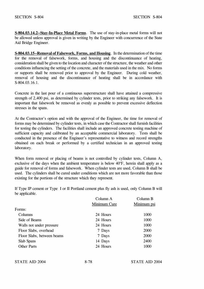
STATE AID 2004 STATE AID 2004
STATE AID 2004 STATE AID 20048-78
SECTION S-804 SECTION S-804
S-804.03.14.2--Stay-In-Place Metal Forms. The use of stay-in-place metal forms will notbe allowed unless approval is given in writing by the Engineer with concurrence of the StateAid Bridge Engineer.
S-804.03.15--Removal of Falsework, Forms, and Housing. In the determination of the timefor the removal of falsework, forms, and housing and the discontinuance of heating,consideration shall be given to the location and character of the structure, the weather and otherconditions influencing the setting of the concrete, and the materials used in the mix. No formsor supports shall be removed prior to approval by the Engineer. During cold weather,removal of housing and the discontinuance of heating shall be in accordance withS-804.03.16.1.
Concrete in the last pour of a continuous superstructure shall have attained a compressivestrength of 2,400 psi, as determined by cylinder tests, prior to striking any falsework. It isimportant that falsework be removed as evenly as possible to prevent excessive deflectionstresses in the spans.
At the Contractor's option and with the approval of the Engineer, the time for removal offorms may be determined by cylinder tests, in which case the Contractor shall furnish facilitiesfor testing the cylinders. The facilities shall include an approved concrete testing machine ofsufficient capacity and calibrated by an acceptable commercial laboratory. Tests shall beconducted in the presence of the Engineer’s representative to witness and record strengthsobtained on each break or performed by a certified technician in an approved testinglaboratory.
When form removal or placing of beams is not controlled by cylinder tests, Column A,exclusive of the days when the ambient temperature is below 40oF, herein shall apply as aguide for removal of forms and falsework. When cylinder tests are used, Column B shall beused. The cylinders shall be cured under conditions which are not more favorable than thoseexisting for the portions of the structure which they represent.
If Type IP cement or Type I or II Portland cement plus fly ash is used, only Column B willbe applicable.
Column A Column B Minimum Cure Minimum psi
Forms:Columns 24 Hours 1000Side of Beams 24 Hours 1000Walls not under pressure 24 Hours 1000Floor Slabs, overhead 7 Days 2000Floor Slabs, between beams 7 Days 2000Slab Spans 14 Days 2400Other Parts 24 Hours 1000
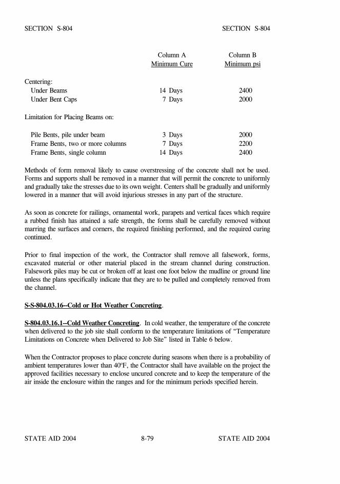
STATE AID 2004 STATE AID 2004
STATE AID 2004 STATE AID 20048-79
SECTION S-804 SECTION S-804
Column A Column BMinimum Cure Minimum psi
Centering:Under Beams 14 Days 2400Under Bent Caps 7 Days 2000
Limitation for Placing Beams on:
Pile Bents, pile under beam 3 Days 2000Frame Bents, two or more columns 7 Days 2200Frame Bents, single column 14 Days 2400
Methods of form removal likely to cause overstressing of the concrete shall not be used.Forms and supports shall be removed in a manner that will permit the concrete to uniformlyand gradually take the stresses due to its own weight. Centers shall be gradually and uniformlylowered in a manner that will avoid injurious stresses in any part of the structure.
As soon as concrete for railings, ornamental work, parapets and vertical faces which requirea rubbed finish has attained a safe strength, the forms shall be carefully removed withoutmarring the surfaces and corners, the required finishing performed, and the required curingcontinued.
Prior to final inspection of the work, the Contractor shall remove all falsework, forms,excavated material or other material placed in the stream channel during construction.Falsework piles may be cut or broken off at least one foot below the mudline or ground lineunless the plans specifically indicate that they are to be pulled and completely removed fromthe channel.
S-S-804.03.16--Cold or Hot Weather Concreting.
S-804.03.16.1--Cold Weather Concreting. In cold weather, the temperature of the concretewhen delivered to the job site shall conform to the temperature limitations of “TemperatureLimitations on Concrete when Delivered to Job Site” listed in Table 6 below.
When the Contractor proposes to place concrete during seasons when there is a probability ofambient temperatures lower than 40oF, the Contractor shall have available on the project theapproved facilities necessary to enclose uncured concrete and to keep the temperature of theair inside the enclosure within the ranges and for the minimum periods specified herein.
STATE AID 2004 STATE AID 2004
STATE AID 2004 STATE AID 20048-80
SECTION S-804 SECTION S-804
When there are indications of temperatures of less than 40oF during the first four days afterplacement of the concrete, the concrete shall be protected from cold temperatures bymaintaining a temperature between 50oF and 100oF for at least four days after placement andbetween 40oF and 100oF for at least three additional days. The Contractor shall use suchheating equipment such as stoves, salamanders, or steam equipment as deemed necessary toprotect the concrete. When dry heat is used, means of maintaining atmospheric moisture shallbe provided.
One or more of the aggregates and/or mixing water may be heated. The aggregates may beheated by steam, dry heat, or by placing in the mixing water which has been heated. Frozenaggregates shall not be used. When either aggregates or water are heated above 100oF, theaggregates and water shall be combined first in the mixer before the cement is added to avoidflash set. Cement shall not be mixed with water or with a mixture of water and aggregatehaving a temperature greater than 100oF.
The use of salt or other chemical admixtures in lieu of heating will not be permitted.
Before placing concrete, all ice or frost shall be removed from the forms and reinforcement.
In the case of concrete placed directly on or in the ground, such as for footings or bottomslabs, a sufficient supply of straw, hay, grass, or other suitable blanketing material shall beprovided to protect the work when the air temperature may be expected to drop below 35oF.The Contractor shall be responsible for the quality and strength of the concrete placed duringcold weather, and all concrete injured by frost action shall be removed and replaced at noadditional cost to the Project. The Engineer reserves the right to perform destructive ornondestructive testing for evaluation of damage caused by cold weather.
The Contractor shall assume all risk and added cost connected with the placing and protectingof concrete during cold weather. Permission given by the Engineer to place concrete duringsuch time will in no way relieve the Contractor of responsibility for satisfactory results.Should it be determined at any time that the concrete placed under such conditions isunsatisfactory, it shall be removed and replaced with satisfactory concrete by the Contractorwithout extra compensation.
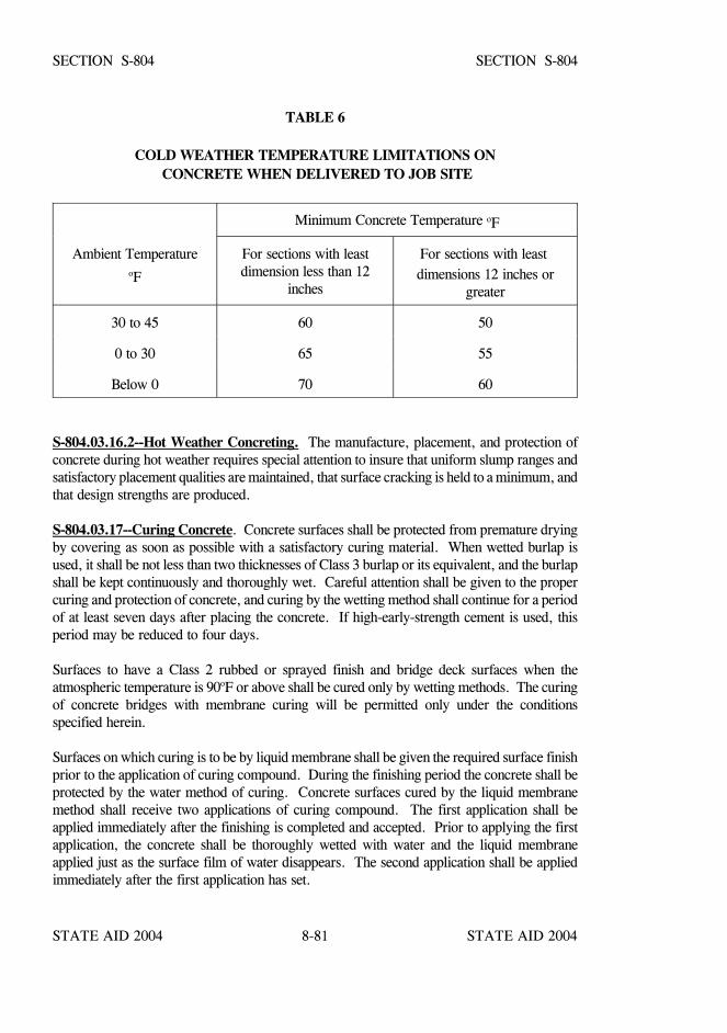
STATE AID 2004 STATE AID 2004
STATE AID 2004 STATE AID 20048-81
SECTION S-804 SECTION S-804
TABLE 6
COLD WEATHER TEMPERATURE LIMITATIONS ON CONCRETE WHEN DELIVERED TO JOB SITE
Minimum Concrete Temperature oF
Ambient TemperatureoF
For sections with leastdimension less than 12
inches
For sections with least dimensions 12 inches or
greater
30 to 45 60 50
0 to 30 65 55
Below 0 70 60
S-804.03.16.2--Hot Weather Concreting. The manufacture, placement, and protection ofconcrete during hot weather requires special attention to insure that uniform slump ranges andsatisfactory placement qualities are maintained, that surface cracking is held to a minimum, andthat design strengths are produced.
S-804.03.17--Curing Concrete. Concrete surfaces shall be protected from premature dryingby covering as soon as possible with a satisfactory curing material. When wetted burlap isused, it shall be not less than two thicknesses of Class 3 burlap or its equivalent, and the burlapshall be kept continuously and thoroughly wet. Careful attention shall be given to the propercuring and protection of concrete, and curing by the wetting method shall continue for a periodof at least seven days after placing the concrete. If high-early-strength cement is used, thisperiod may be reduced to four days.
Surfaces to have a Class 2 rubbed or sprayed finish and bridge deck surfaces when theatmospheric temperature is 90oF or above shall be cured only by wetting methods. The curingof concrete bridges with membrane curing will be permitted only under the conditionsspecified herein.
Surfaces on which curing is to be by liquid membrane shall be given the required surface finishprior to the application of curing compound. During the finishing period the concrete shall beprotected by the water method of curing. Concrete surfaces cured by the liquid membranemethod shall receive two applications of curing compound. The first application shall beapplied immediately after the finishing is completed and accepted. Prior to applying the firstapplication, the concrete shall be thoroughly wetted with water and the liquid membraneapplied just as the surface film of water disappears. The second application shall be appliedimmediately after the first application has set.
STATE AID 2004 STATE AID 2004
STATE AID 2004 STATE AID 20048-82
SECTION S-804 SECTION S-804
The rate of application of curing compound will be as prescribed by the Engineer with aminimum spreading rate per application of one gallon per 200 square feet of concrete surface.The coating shall be protected against marring for at least 10 days after the application of thecuring compound. The coating on bridge decks shall receive extra attention and may requireadditional protection as required by the Engineer. All membrane marred or otherwisedisturbed shall be given an additional coating. Should the surface coating be subjectedrepeatedly to injury, the Engineer may require that the water curing method be applied at once.
When using curing compound, the compound should be thoroughly mixed within an hourbefore use. If the use of curing compound results in a streaked or blotched appearance, themethod shall be stopped and water curing applied until the cause of defective appearance iscorrected.
Other precautions to insure the development of strength shall be taken as directed.
Adequate tarpaulins of ample size shall be on the project and used as necessary to protect thework in case of rain or other emergencies.
Conditions governing the placement of concrete and the requirements for the placement,protection, and curing of concrete during cold or hot weather shall conform to the limitations,conditions, and requirements stipulated in S-804.03.16 as applicable.
S-804.03.18--Expansion and Fixed Joints, Bearings, Anchor Bolts, Plates, Castings,Pipes, Drains, Conduits, Etc. All joints shall be constructed according to details shown onthe plans. The edges of the concrete at open or filled joints shall be chamfered or edged asindicated on the plans.
S-804.03.18.1--Open Joints. Open joints shall be placed in the locations shown on the plansand shall be constructed by the insertion and subsequent removal of a wood strip, metal plate,or other approved material. The insertion and removal of the template shall be accomplishedwithout chipping or breaking the corners of the concrete. Reinforcement shall not extendacross an open joint unless so specified on the plans.
S-804.03.18.2--Filled Joints. Poured expansion joints and joints to be sealed with premoldedmaterials shall be constructed similar to open joints. When premolded types are specified, thefiller shall be placed in correct position as the concrete on one side of the joint is placed.When the form is removed, the concrete on the other side shall be placed. Adequate waterstops of metal, rubber, or plastic shall be carefully placed as shown on the plans.
STATE AID 2004 STATE AID 2004
STATE AID 2004 STATE AID 20048-83
SECTION S-804 SECTION S-804
S-804.03.18.3--Premolded and Preformed Joint Seals. When preformed elastomericcompressive joint seals are specified, the previously formed and cured open joint shall bethoroughly cleaned of all foreign matter, the required adhesive uniformly applied, and the sealinstalled in accordance with the recommendations of the manufacturer of the seal.
When premolded filler is used for the joints in the roadway slab, the tops shall be adequatelysealed with poured joint filler in accordance with details on the plans. Premolded filler shallbe permanently fastened to an adjacent concrete surface by appropriate use of copper wire,copper nails, or galvanized nails.
S-804.03.18.4--Steel Joints. The plates, angles, or other structural shapes shall be accuratelyshaped at the shop to conform to the section of the concrete floor. Fabrication and paintingshall conform to the specifications covering those items. When called for on the plans or inthe special provisions, the material shall be galvanized in lieu of painting. Care shall be takento insure that the surface in the finished plane is true and free of warping. Positive methodsshall be employed in placing the joints to keep them in correct position during the placing ofthe concrete. The opening at expansion joints shall be that designated on the plans at normaltemperature, and care shall be taken to avoid impairment of the clearance in any manner.
S-804.03.18.5--Water Stops. Adequate water stops of metal, rubber, or plastic shall beplaced as shown on the plans. Where movement at the joint is provided for, the water stopsshall be of a type permitting movement without injury. They shall be spliced, welded, orsoldered to form continuous watertight joints.
S-804.03.18.6--Bearing Devices. Bearing plates, rockers, and other bearing devices shall beconstructed according to details shown on the plans. Unless otherwise specified or set inplastic concrete, they shall be set in grout to insure uniform bearing. Structural steel andpainting shall conform to the requirements of S- 810 and S-814. When specified, the materialshall be galvanized in lieu of painting. The rockers or other expansion bearing devices shallbe set, considering the temperature at the time of erection, so that the required position of thedevice is provided.
At all points of bearing contact, concrete members shall be separated from underlyingmembers by dimensioned bearing pads or by methods and/or materials specified on the plans.
When not otherwise specifically provided, contact areas between concrete super-structures andsubstructures shall be separated by three layers of No. 15, Type I, roofing felt.
S-804.03.18.7--Friction Joints. Metal friction joints shall consist of plates as indicated on theplans and shall be securely anchored in correct position. All sliding surfaces shall bethoroughly coated with an approved graphite grease. Movement shall not be impeded by theconcrete in which the plates are embedded.
STATE AID 2004 STATE AID 2004
STATE AID 2004 STATE AID 20048-84
SECTION S-804 SECTION S-804
S-804.03.18.8--Placing Anchor Bolts, Plates, Castings, Grillage, Conduits, Etc. All anchorbolts, plates, castings, grillage, conduits, etc. indicated on the plans to be placed in or on theconcrete shall be placed, set, or embedded as indicated or as directed. These items of theconstruction shall be set in portland cement mortar as referenced in S-714.11.5, except thatanchor bolts may, as permitted by the Engineer, be built into the masonry, set in drilled holes,or placed as the concrete is being constructed by inserting encasing pipe or oiled wooden formsof sufficient size to allow for adjustment of the bolts. After removal of the pipe or forms, thespace around the bolts shall be filled with portland cement mortar completely filling the holes.The bolt shall be set accurately and perpendicular to the plane of the seat.
Anchor bolts which are to be set in the masonry prior to the erection of the superstructure shallbe carefully set to proper location and elevation with a template or by other suitable means.
When bed plates are set in mortar, no superstructure or other load shall be placed thereon untilthis mortar has been allowed to set for a period of at least 96 hours, subject to the restrictionsfor cold weather concreting in S-804.03.16.1. The mortar shall be kept well moistened duringthis period.
Weep hole drains shall be installed in abutments and retaining walls, and roadway drains orscuppers shall be installed in the roadway slabs in accordance with the details shown on theplans.
Where backfill is to be made at weep holes or openings in the structure, sand or stonechimneys or French drains shall be constructed as specified and shall extend through theportion of the backfill to be drained. Except as otherwise provided, the sand, stone, or slagused in this construction shall meet the requirements of S-704.04.
S-804.03.19--Finishing Concrete Surfaces.
S-804.03.19.1--Classes of Finishes. Surface finishes of exposed concrete surfaces shall beclassified as follows:
Class 1 - Ordinary Surface Finish Class 2 - Rubbed or Spray Finish Class 3 - Tooled Finish Class 4 - Sand-Blast Finish Class 5 - Wirebrush or Scrubbed Finish Class 6 - Floated Surface Finish
STATE AID 2004 STATE AID 2004
STATE AID 2004 STATE AID 20048-85
SECTION S-804 SECTION S-804
S-804.03.19.2--Class 1, Ordinary Surface Finish. Immediately following the removal offorms, all fins and irregular projections shall be removed from all surfaces except from thosewhich are not to be exposed or not to be waterproofed. On all surfaces, the cavities producedby form ties and all other holes, honeycomb spots, broken corners or edges, and other defectsshall be thoroughly cleaned, and after having been kept saturated with water for at least threehours shall be carefully pointed and trued with a mortar of cement and fine aggregate mixedin the proportions used in the class of the concrete being finished. Mortar used in pointingshall be not more than one hour old. The mortar patches shall be cured as specified underS-804.03.17. All construction and expansion joints shall be left carefully tooled and free ofmortar and concrete. The joint filler shall be left exposed for its full length with clean and trueedges.
The resulting surfaces shall be true and uniform. All surfaces which cannot be repaired to thesatisfaction of the Engineer shall be given a Class 2 rubbed finish.
S-804.03.19.3--Class 2, Rubbed or Spray Finish.
S-804.03.19.3.1--Rubbed Finish. After removal of forms, the Class 1 finish shall becompleted and the rubbing of concrete shall be started as soon as its condition will permit.Immediately before starting this work, the concrete shall be kept thoroughly saturated withwater for at least three hours. Surfaces shall be rubbed with a medium course Carborundumstone using a small amount of mortar on its face. The mortar shall be composed of cement andsand mixed in the proportions used in the concrete being finished. Rubbing shall be continueduntil all form marks, projections, and irregularities have been removed, all voids are filled, anda uniform surface has been obtained. The paste produced by this rubbing shall be left in placeat this time.
After all concrete above the surface being treated has been cast, the final finish shall beobtained by rubbing with a fine Carborundum stone and water. This rubbing shall continueuntil the entire surface is of a smooth texture and uniform color.
After the final rubbing is completed and the surface has dried, it shall be rubbed with burlapto remove loose powder and objectionable marks.
S-804.03.19.3.2--Spray Finish. Prior to the spray finish, the concrete shall be given a Class1 finish in accordance with S-804.03.19.2, supplemented if necessary with a grout meeting therequirements of S--714.11 with fine aggregate modified to require 100 percent passing the No.16 Sieve.
Grout shall be applied with burlap pads or float sponges, and as soon as the grout has dried thesurface shall be brushed to remove all loose grout and the surface left smooth and free of airholes. Surfaces to be sprayed shall be free of efflorescence, flaking coatings, dirt, oil, andother foreign substances. Prior to application of the spray finish, the surfaces shall be free ofmoisture, as determined by sight and touch, and in a condition consistent with themanufacturer's published recommendations.

STATE AID 2004 STATE AID 2004
STATE AID 2004 STATE AID 20048-86
SECTION S-804 SECTION S-804
The spray finish material shall meet the requirements of S-714.12 and shall be listed onMDOT’s Approved Sources of Materials. The spray finish shall be applied with heavy dutyspray equipment capable of maintaining a constant pressure as necessary for properapplication. The material shall be applied as recommended by the manufacturer except the rateof application shall not be less than one gallon per 50 square feet of surface area without priorwritten approval of the Engineer.
The completed finish shall be tightly bonded to the structure and present a uniform appearanceand texture equal to or better than a rubbed finish. If necessary, additional coats shall besprayed to produce the desired surface texture and uniformity. Upon failure to adherepositively to the structure without chipping or cracking or to attain the desired surfaceappearance, the coatings shall be completely removed and the surface given a rubbed finish inaccordance with S-804.03.19.3.1, or other approved methods shall be used to obtain thedesired surface finish to the satisfaction of the Engineer without additional cost to the Project.
S-804.03.19.4--Classes 3, 4, and 5 Finishes. If required, specifications for these finishes willbe contained in the special provisions.
S-804.03.19.5--Class 6, Floated Surface Finish. After the concrete has been deposited inplace, it shall be consolidated and the surface shall be struck off by means of a strike board andfloated with a wooden or cork float. An edging tool shall be used on edges and expansionjoints. The surface shall not vary more than 1/8 inch under a 10-foot straightedge. Thesurface shall have a granular or matte texture which will not be slick when wet.
S-804.03.19.6--Required Finishes for Various Surfaces.
S-804.03.19.6.1--General. Unless otherwise specified, the top surface of sidewalks, the tophorizontal surfaces of footings, and top slabs of box bridges, box culverts, or other structuresshall be given a Class 6 finish. All formed concrete surfaces shall be given a Class 1 finish,except on surfaces which are completely enclosed, such as the inside surfaces of cells of boxgirders, the removal of fins and form marks and the rubbing of mortared surfaces to a uniformcolor will not be required.
In reference to finishing, exposed surfaces are surfaces or faces which may be seen after allbackfill has been placed. Exposed surfaces requiring a Class 2 finish shall be finished at leastone foot below the ground line or the low water elevation, whichever is higher.
The Class 2 finish shall be made upon a Class 1 finish. After the removal of forms the Class1 finish shall be completed and the rubbing of concrete shall be started as soon as the conditionof the concrete will permit.
Bridge floors shall be finished in accordance with S-804.03.19.7.
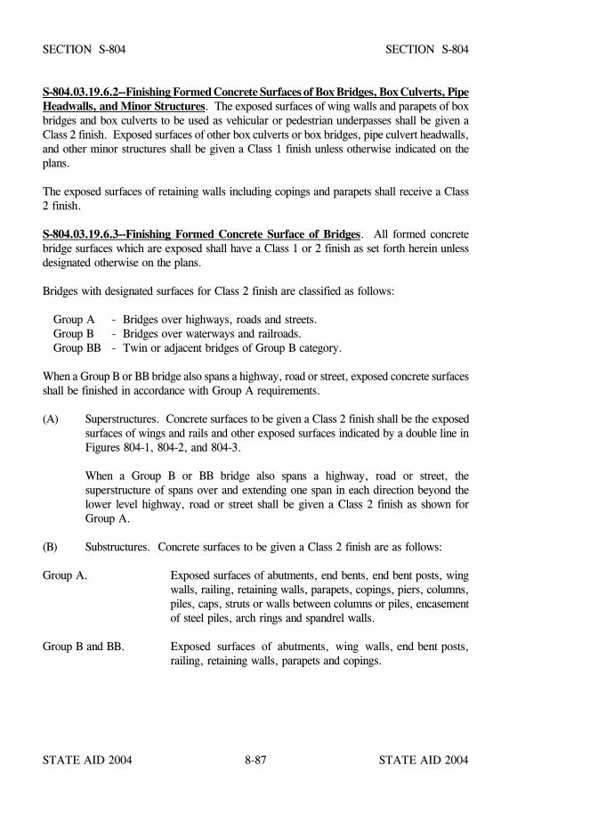
STATE AID 2004 STATE AID 2004
STATE AID 2004 STATE AID 20048-87
SECTION S-804 SECTION S-804
S-804.03.19.6.2--Finishing Formed Concrete Surfaces of Box Bridges, Box Culverts, PipeHeadwalls, and Minor Structures. The exposed surfaces of wing walls and parapets of boxbridges and box culverts to be used as vehicular or pedestrian underpasses shall be given aClass 2 finish. Exposed surfaces of other box culverts or box bridges, pipe culvert headwalls,and other minor structures shall be given a Class 1 finish unless otherwise indicated on theplans.
The exposed surfaces of retaining walls including copings and parapets shall receive a Class2 finish.
S-804.03.19.6.3--Finishing Formed Concrete Surface of Bridges. All formed concretebridge surfaces which are exposed shall have a Class 1 or 2 finish as set forth herein unlessdesignated otherwise on the plans.
Bridges with designated surfaces for Class 2 finish are classified as follows:
Group A - Bridges over highways, roads and streets.Group B - Bridges over waterways and railroads.Group BB - Twin or adjacent bridges of Group B category.
When a Group B or BB bridge also spans a highway, road or street, exposed concrete surfacesshall be finished in accordance with Group A requirements.
(A) Superstructures. Concrete surfaces to be given a Class 2 finish shall be the exposedsurfaces of wings and rails and other exposed surfaces indicated by a double line inFigures 804-1, 804-2, and 804-3.
When a Group B or BB bridge also spans a highway, road or street, thesuperstructure of spans over and extending one span in each direction beyond thelower level highway, road or street shall be given a Class 2 finish as shown forGroup A.
(B) Substructures. Concrete surfaces to be given a Class 2 finish are as follows:
Group A. Exposed surfaces of abutments, end bents, end bent posts, wingwalls, railing, retaining walls, parapets, copings, piers, columns,piles, caps, struts or walls between columns or piles, encasementof steel piles, arch rings and spandrel walls.
Group B and BB. Exposed surfaces of abutments, wing walls, end bent posts,railing, retaining walls, parapets and copings.
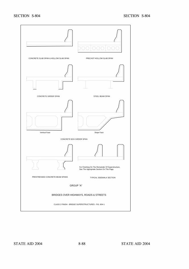
STATE AID 2004 STATE AID 2004
STATE AID 2004 STATE AID 20048-88
CONCRETE SLAB SPAN & HOLLOW SLAB SPAN PRECAST HOLLOW SLAB SPAN
CONCRETE GIRDER SPAN STEEL BEAM SPAN
Vertical Face Slope Face
CONCRETE BOX GIRDER SPAN
For Finishing On The Remainder Of Superstructure,See The Appropriate Section On This Page.
PRESTRESSED CONCRETE BEAM SPANS TYPICAL SIDEWALK SECTION
GROUP "A"
BRIDGES OVER HIGHWAYS, ROADS & STREETS
CLASS 2 FINISH - BRIDGE SUPERSTRUCTURES - FIG. 804-1
SECTION S-804 SECTION S-804
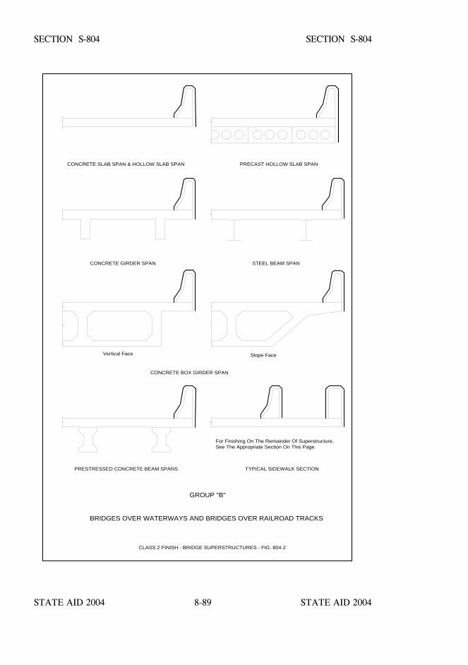
STATE AID 2004 STATE AID 2004
STATE AID 2004 STATE AID 20048-89
CONCRETE SLAB SPAN & HOLLOW SLAB SPAN PRECAST HOLLOW SLAB SPAN
CONCRETE GIRDER SPAN STEEL BEAM SPAN
Vertical Face Slope Face
CONCRETE BOX GIRDER SPAN
For Finishing On The Remainder Of Superstructure,See The Appropriate Section On This Page.
PRESTRESSED CONCRETE BEAM SPANS TYPICAL SIDEWALK SECTION
GROUP "B"
BRIDGES OVER WATERWAYS AND BRIDGES OVER RAILROAD TRACKS
CLASS 2 FINISH - BRIDGE SUPERSTRUCTURES - FIG. 804-2
SECTION S-804 SECTION S-804
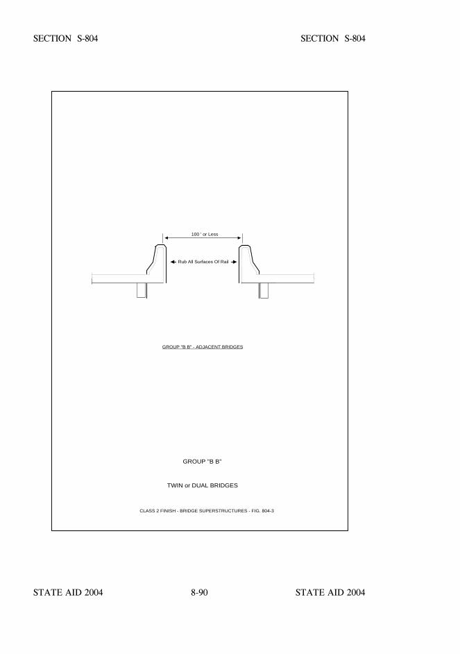
STATE AID 2004 STATE AID 2004
STATE AID 2004 STATE AID 20048-90
SECTION S-804 SECTION S-804
GROUP "B B" - ADJACENT BRIDGES
GROUP "B B"
TWIN or DUAL BRIDGES
CLASS 2 FINISH - BRIDGE SUPERSTRUCTURES - FIG. 804-3
Rub All Surfaces Of Rail
100 ' or Less
STATE AID 2004 STATE AID 2004
STATE AID 2004 STATE AID 20048-91
SECTION S-804 SECTION S-804
S-804.03.19.7--Finishing Bridge Floors.
S-804.03.19.7.1--General. Concrete bridge decks shall be struck off and finished by themethod(s) designated on the plans.
In the event a method is not designated, the Contractor may use either the longitudinal ortransverse method subject to the requirements contained in these specifications.
Except when indicated otherwise on the plans, the final surface texture of the bridge floor shallbe either a drag, belt, or broom finish. The surface texture specified and surface requirementsshall be in accordance with the following:
Final Strike-Off, Consolidation and Finishing.
Sequence. The sequence of operations shall be the strike-off and consolidation, floating andremoval of laitance, straight-edging, and final surface finish. If a finish is not designated, thefinish shall be a belt finish.
Concrete, as soon as placed, shall be struck off and screeded. An approved portable screedshall be used. A second screed shall be provided for striking off the bottom layer of concreteif reinforcement is used and the pavement is placed in two layers.
The screed for the surface shall be at least two feet longer than the maximum width of the slabto be struck off. It shall be of approved design, sufficiently rigid to retain its shape, and beconstructed of metal or of other suitable material shod with metal.
Consolidation shall be attained by the use of a suitable vibrator or other approved equipment.
In operation the screed shall be moved forward with a combined longitudinal and transverseshearing motion, and manipulated so that neither end is raised from the side forms during thestriking off process. If necessary, this shall be repeated until the surface is of uniform texture,true to grade and cross section, and free from porous areas.
In general, the addition of superficial water to the surface of the concrete to assist in finishingoperations will not be permitted. If the application of water to the surface is permitted, it shallbe applied as a fog spray by means of approved spray equipment.
STATE AID 2004 STATE AID 2004
STATE AID 2004 STATE AID 20048-92
SECTION S-804 SECTION S-804
Finishing at Joints. The concrete adjacent to joints shall be compacted or firmly placedwithout voids or segregation against the joint material, and also under and around all loadtransfer devices, joint assembly units, and other features designed to extend into the pavement.Concrete adjacent to joints shall be mechanically vibrated.
After the concrete has been placed and vibrated adjacent to the joints, the finishing machineshall be brought forward, operating in a manner to avoid damage or misalignment of joints.If uninterrupted operation of the finishing machine, to, over, and beyond the joints causessegregation of concrete, damage to, or misalignment of the joints, the finishing machine shallbe stopped when the front screed is approximately eight inches from the joint. Segregatedconcrete shall be removed from in front of and off the joint, and the front screed shall be liftedand set directly on top of the joint and the forward motion of the finishing machine resumed.When the second screed is close enough to permit the excess mortar in front of it to flow overthe joint, it shall be lifted and carried over the joint. Thereafter, the finishing machine may berun over the joint without lifting the screeds, provided there is no segregated concreteimmediately between the joint and the screed or on top of the joint.
Machine Finishing. Unless otherwise specified, full width vibration shall be performed. Ifuniform and satisfactory density of the concrete is not obtained by the vibratory method atjoints, along forms, at structures, and throughout the pavement, the Contractor shall furnishequipment and methods which will produce pavement conforming to the specifications.
Hand Finishing. Unless otherwise specified, hand finishing methods, other than the handfloating method described below, will not be permitted except under the following conditions:
In the event of breakdown of the mechanical equipment, hand methods may be used to finishthe concrete already deposited on the grade when the breakdown occurs.
Narrow widths or areas where operation of mechanical equipment is impractical may befinished by hand methods.
Floating. After the concrete has been struck off and consolidated, it shall be further smoothedand trued by means of a longitudinal float, using one of the following methods as specified:
(a) Hand Method. The hand-operated longitudinal float shall be at least 12 feet longand six inches wide, properly stiffened to prevent flexibility and warping. Thelongitudinal float, operated from foot bridges spanning but not touching theconcrete, shall be worked with a sawing motion while held in a floating positionparallel to the road centerline, and passing gradually from one side of the pavementto the other. Movement ahead along the centerline of the pavement shall be insuccessive advances of not more than one-half the length of the float. Excesswater and soupy material shall be wasted over the sides on each pass.
STATE AID 2004 STATE AID 2004
STATE AID 2004 STATE AID 20048-93
SECTION S-804 SECTION S-804
(b) Mechanical Method. The mechanical longitudinal float shall be of a designapproved by the Engineer, and shall be in good working condition. The float shallbe accurately adjusted to the required crown, and coordinated with the adjustmentsof the transverse finishing machine so that a small amount of mortar is carriedahead of the float at all times. The float shall pass over each area of pavement atleast two times, but excessive operation over a given area will not be permitted.Excess water and soupy material shall be wasted over the sides on each pass.
As an alternative to the mechanical method, the Contractor may use a machinecomposed of a cutting and smoothing float, or floats, suspended from and guidedby a rigid frame. The frame shall be carried by four or more visible wheelsriding on and constantly in contact with the side forms, or track line of aslip-form paver.
If necessary, following one of the preceding methods of floating, long-handled floats havingblades at least five feet long and six inches wide may be used to smooth and fill inopen-textured areas in the pavement. Long-handled floats shall not be used to float the entiresurface of the pavement in lieu of, or to supplement, one of the preceding methods of floating.When strike-off and consolidation are done by the hand method and the crown of the pavementwill not permit the use of the longitudinal float, the surface shall be floated transversely bymeans of the long-handled float. Care shall be taken not to work the crown out of thepavement during the operation. After floating, excess water and laitance shall be removedfrom the surface of the pavement by a straightedge 10 feet or more in length. Successive dragsshall be lapped one-half the length of the blade.
Straight-Edge Testing and Surface Correction. After the floating has been completed andwhile the concrete is still plastic, the surface of the concrete shall be tested with a 10 footstraightedge. For this purpose the Contractor shall furnish and use an accurate 10-footstraightedge swung from handles three feet longer than one-half the width of the slab. Thestraightedge shall be held in contact with the surface in successive positions parallel to the roadcenterline and the whole area gone over from one side of the slab to the other as necessary.Advance along the road shall be in successive stages of not more than one-half the length ofthe straightedge. All depressions found shall be immediately filled with freshly mixedconcrete, struck off, consolidated, and refinished. High areas shall be cut down and refinished.Special attention shall be given to assure that the surface across joints is smooth and to grade.Straightedge testing and surface corrections shall continue until the entire surface is found tobe free from observable departures from the straightedge, and the slab conforms to therequired grade and cross section.
Final Finish. The surface finish of the concrete shall be that designated on the plans and inthe bid schedule of the contract. If a finish is not designated, the finish shall be a belt finish.
STATE AID 2004 STATE AID 2004
STATE AID 2004 STATE AID 20048-94
SECTION S-804 SECTION S-804
Drag Finish. This finish shall consist of a uniform surface of gritty texture produced bydragging a seamless strip of damp burlap or cotton fabric longitudinally along the full widthof pavement. For pavement 16 feet or more in width, the drag shall be mounted on a bridgewhich travels on the forms or track line. The dimensions of the drag shall be such that a stripof burlap or fabric at least three feet wide is in contact with the full width of pavement surfacewhile the drag is used. The drag shall consist of at least two layers of burlap with the bottomlayer approximately six inches wider than the upper layer. The drag shall be maintained in acondition that will produce a surface of uniform appearance with corrugations approximatelyone-sixteenth inch in depth. Drags shall be maintained clean and free from encrusted mortar.Drags that cannot be cleaned shall be discarded and new drags substituted.
Broom Finish. A broom finish shall be applied when the water sheen has practicallydisappeared. The broom shall be drawn from the center to the edge of the pavement withadjacent strokes slightly overlapping. The brooming operations shall produce corrugations inthe surface that are uniform in appearance and not more than 1/16 inch in depth. Broomingshall be completed before the concrete has set to a degree that the surface will be torn orunduly roughened by the operation. The finished surface shall be free from rough and porousareas, irregularities, and depressions. Brooms shall be of the quality, size, and constructionand operated so as to produce a surface finish meeting the approval of the Engineer. Subjectto satisfactory results being obtained and approval of the Engineer, the Contractor will bepermitted to substitute mechanical brooming in lieu of manual brooming as herein described.
Belt Finish. When straight-edging is complete and the water sheen has practically disappearedand just before the concrete becomes nonplastic, the surface shall be belted with a two-plycanvas belt eight inches wide and at least three feet longer than the pavement width. Handbelts shall have suitable handles to permit controlled, uniform manipulation. The belt shall beoperated with short strokes transverse to the road centerline and with a rapid advance parallelto the center line. Subject to satisfactory results being obtained and approval of the Engineer,the Contractor will be permitted to substitute mechanical belting in lieu of manual belting asherein described.
Transverse Tine Finish. The surface shall first be given a drag finish. After completion ofthe drag finish, the pavement shall be given an additional texture by transverse tining.
The final surface texture shall be produced with a metal tine finishing device. The texturingdevice shall be so constructed and operated as to produce uniform parallel groovesperpendicular to the centerline of the pavement 1/2 inch on centers and having a depth of 1/8inch, plus or minus 1/32 inch.
The metal tine device shall be operated by approved mechanical means when texturing mainroadway pavement lanes. Manual methods may be used for texturing small irregular areasinaccessible to the texturing machine.
STATE AID 2004 STATE AID 2004
STATE AID 2004 STATE AID 20048-95
SECTION S-804 SECTION S-804
The depth of the finished grooves will be determined by the use of a standard commercial tiretread depth measuring gage with 1/32 inch graduations that can be easily and accurately read,a brass wire brush, and a steel straightedge approximately 1/4 inch x 1 inch x 12 inches. TheContractor shall furnish this equipment for use by and subject to the approval of the Engineer.
If for any reason the concrete hardens to the extent that the tining equipment does not providegrooving in accordance with these requirements, or if rainfall damages the finish and theEngineer permits the concrete to remain in place, the Contractor shall use other approveddevices such as saws to construct the grooves substantially in accordance with the requirementsspecified herein.
Transverse Grooved Finish. After the concrete has cured for a minimum of seven (7) days,areas to be transverse grooved shall be grooved with a sawing device. Grooves shall beperpendicular to the centerline of the roadway and extend as close as possible to the edge butin no case more that two (2) feet from the edge, gutter line, etc. The tolerance for the widthof the groove is +1/16" to -0" and the tolerance for the depth and spacing of the grooves is±1/16".
Edging at Forms and Joints. After the final finish, but before the concrete has taken itsinitial set, the pavement along each side of each slab, and on each side of transverse expansionjoints, formed joints, transverse construction joints, and emergency construction joints shall beworked with an approved tool and rounded to the radius required by the plans. A well-definedand continuous radius shall be produced and a smooth, dense, mortar finish obtained. Thesurface of the slab shall not be unduly disturbed by tilting of the tool during use.
At all joints, all tool marks appearing on the slab adjacent to the joints shall be eliminated bybrooming the surface. In doing this, the rounding of the corner of the slab shall not bedisturbed. All concrete on top of the joint filler shall be completely removed.
All joints shall be tested with a straightedge before the concrete has set, and correction madeif one side of the joint is higher than the other, or if they are higher or lower than the adjacentslabs.
S-804.03.19.7.2--Longitudinal Method. The longitudinal method requires that the strike-offscreed be supported on accurately graded and supported bulkheads or templates placed acrossthe full width at the end(s) of the pour. Before the concrete is placed, approved fixedtemplates or wooden bulkheads of not less than 1¼-inch lumber shall be placed perpendicularto the centerline of the roadway, or in the case of skew bridges at the angle of skew. Theupper surface of the template or bulkheads shall be accurately set to conform to the requiredgrade and crown.
STATE AID 2004 STATE AID 2004
STATE AID 2004 STATE AID 20048-96
SECTION S-804 SECTION S-804
Special attention shall be given to the gutter lines where the strike-off screed cannot reach. Thegutters shall be finished by hand and tested with the straight edge. Floor drains shall be setlower than the finished gutter line and finished over. After initial set, the concrete shall bedished out and finished around the drains to form an outlet.
After the concrete has been deposited and rough graded, it shall be struck off by means of astrike-off screed resting on the bulkheads or fixed templates. The strike-off screed shall be ofa type satisfactory to the Engineer and shall have sufficient strength to retain its shape underall working conditions. The final surface shall comply with the applicable requirements above,and unless otherwise specified in the contract, the final finish under this method shall be thebelt finish.
In general, the overall strike-off screed should be trussed, with bracing heavy enough tosupport the weight of a man without deflecting, and should be adjustable for camber andcorrection of sag.
The strike-off screed will ride on the bulkheads or fixed templates at the ends of the sectionbeing finished. Care shall be taken to see that the bulkhead or fixed template elevations areaccurately set since the entire span surface will be controlled by them. The manipulation ofthe screed shall be such that neither end is raised from the bulkheads or templates during theprocess.
The concrete shall be struck off by beginning at one curb and proceeding entirely across thespan. A slight excess of concrete shall be kept in front of the cutting edge at all times. Thisoperation shall be repeated at least three times. In each case, the strike-off screed shall bepicked up and carried back to the point of beginning. No backward strokes will be allowed.The strike-off screed shall be moved along the bulkheads or fixed templates with a combinedlongitudinal and transverse motion. This operation may be manual or mechanical. Standingor walking in the fresh concrete ahead of the strike- off screed will not be permitted.
S-804.03.19.7.3--Transverse Method. The transverse method requires that the screedingequipment be supported on accurately graded and supported rails placed beyond the gutter linesand parallel with the centerline of the bridge.
The machine shall be so constructed and operated as to produce a bridge floor of uniformdensity with minimum manipulation of the fresh concrete and achieved in the shortest possibletime. Manual transverse methods of screeding will not be permitted.
STATE AID 2004 STATE AID 2004
STATE AID 2004 STATE AID 20048-97
SECTION S-804 SECTION S-804
The finishing machine shall be supported on vertically adjustable rails set a sufficient distancefrom the gutter line to allow free movement of the screed from gutter line to gutter line.Satisfactory means of load distribution with minimum rail deflection shall be provided. Thescreed rails for a deck pour shall be completely in place for the full length of the pour and shallbe firmly secured prior to placing concrete. The screed rails shall be adjusted as necessary tocompensate for settlement and deflection occurring during the screeding operations. Supportsfor the screed rail shall be located directly over slab overhang support brackets as referencedin S-804.03.14.1.
At least one dry run shall be made the length of each pour with a "tell-tail" device attached tothe screed carriage to assure the specified clearance to the reinforcing steel.
The screed shall be equipped with a metal cutting edge or other approved mechanical meansfor accurately fine grading the plastic concrete to the required grade and surface smoothnessand shall be supported by a bridging structure sufficiently rigid and heavy to performoperations satisfactorily on concrete of minimum slump without vibration, distortion, andwrecking of forms. The screed shall be mechanically actuated to deliver the screeding actionand for travel in a longitudinal direction at a uniform rate along the bridge floor.
The screed shall complete sufficient passes to strike off all of the excessconcrete with ample mortar along the entire leading edge to assure filling oflow spots. Care shall be taken to remove all objectionable material from thegutters where final hand finishing will be required.
The selection of the transverse method may require the Contractor to furnish bridge deckconcrete which contains an approved water-reducing set retarding admixture in the quantitiesapproved by the Engineer at no additional cost to the Project. See S-713.02 for moreinformation.
Other finishing requirements shall be in accordance with the general requirements inS-804.03.19.7.1 and as specified on the plans.
S-804.03.19.7.4-Acceptance Procedure for Bridge Deck Smoothness. Bridges mustmeet a 1/8 inch in 10-foot straightedge requirement in longitudinal and transverse directions.
S-804.03.19.7.4.1--Grinding Bridge Decks.
S-804.03.19.7.4.1.1--Equipment. The grinding equipment shall be a power driven,self-propelled machine that is specifically designed to smooth and texture Portland cementconcrete pavement with diamond blades. The effective wheel base of the machine shall not beless than 12.0 feet. It shall have a set of pivoting tandem bogey wheels at the front of themachine and the rear wheels shall be arranged to travel in the track of the fresh cut pavement.The center of the grinding head shall be no further than 3.0 feet forward from the center of theback wheels.
STATE AID 2004 STATE AID 2004
STATE AID 2004 STATE AID 20048-98
SECTION S-804 SECTION S-804
The equipment shall be of a size that will cut or plane at least 3.0 feet wide. It shall also beof a shape and dimension that does not encroach on traffic movement outside of the work area.The equipment shall be capable of grinding the surface without causing spalls at cracks, joints,or other locations.
S-804.03.19.7.4.1.2--Grinding. The grinding areas will be determined by the Contractor,based on the 10 foot straightedge test, and approved by the Engineer. The Contractor shalldevelop and submit to the Engineer for approval a Grinding Plan. The Contractor shall allowup to 45 days for the Engineer to review the Plan prior to starting any grinding operations.This plan shall include as a minimum:
(1) Name of the project superintendent in responsible charge of the grindingoperation.
(2) List and description of all equipment to be used.(3) Maximum depth of each pass allowed by the grinding equipment.(4) Maximum width of each pass allowed by the grinding equipment.(5) Details of a sequence of the grinding operation.(6) Data showing reinforcing steel clearance in all areas to be ground.(7) A detailed drawing of the deck showing areas to be ground with station
numbers and grinding depths clearly indicated.(8) A description of grinding in areas where drains are in conflict with grind
areas.(9) Details of any changes in deck drainage, anticipated ponding, etc.
The Engineer will evaluate the grinding plan for conformance with the plans andspecifications, after which the Engineer will notify the Contractor of any additional informationrequired and/or changes that may be needed. Any part of the plan that is unacceptable will berejected and the Contractor shall submit changes for reevaluation. All approvals given by theEngineer shall be subject to trial and satisfactory performance in the field, and shall not relievethe Contractor of the responsibility to satisfactorily complete the work.
The construction operation shall be scheduled and proceed in a manner that produces a uniformfinished surface. Grinding will be accomplished in a manner that eliminates joint or crackfaults while providing positive lateral drainage by maintaining a constant cross-slope betweengrinding extremities in each lane. Auxiliary or ramp lane grinding shall transition as requiredfrom the mainline edge to provide positive drainage and acceptable riding surface.
The operation shall result in a finished surface that conforms as close as possible to the typicalcross-section and the requirements specified in S-804.03.19.7.4.1.3.
The Contractor shall establish positive means for removal of grinding residue. Residue shallnot be permitted to flow across lanes used by public traffic or into gutters or drainage facilities.
STATE AID 2004 STATE AID 2004
STATE AID 2004 STATE AID 20048-99
SECTION S-804 SECTION S-804
S-804.03.19.7.4.1.3--Final Surface Finish. The grinding process shall produce a finishsurface that is as close as possible to grade and uniform in appearance with a longitudinal linetype texture. The line type texture shall contain parallel longitudinal corrugations that presenta narrow ridge corduroy type appearance. The peaks of the ridges shall be approximately 1/16inch higher than the bottoms of the grooves with approximately 53 to 57 evenly spacedgrooves per foot. Grinding chip thickness shall be a minimum of 0.080 inches thick.
The finished bridge decks and bridge end slabs shall be retested for smoothness as perS-804.03.19.7.4.
S-804.03.19.8--Finishing Horizontal Surfaces of Footings or Top Slabs of Box Bridges,Culverts, or Other Structures. The finishing of horizontal surfaces of footing or top slabsof box bridges, culverts, or other structures shall be achieved by placing an excess of materialin the form and removing or striking off the excess with a template, forcing the coarseaggregate below the mortar surface. After the concrete has been struck off the surface shallbe given a Class 6 finish.
S-804.03.19.9--Finishing Exposed Surfaces of Sidewalks. After the concrete has beendeposited in place it shall be consolidated and the exposed surface shall be given a Class 6finish. An edging tool of the required radius shall be used on all edges and at all expansionjoints. The surface shall have a granular texture which will not be slick when wet.
Sidewalk surfaces shall be laid out in blocks with an approved grooving tool as shown on theplans or as directed.
S-804.03.20--Opening Bridges.
S-804.03.20.1--Public Traffic. Unless otherwise specified, concrete bridge floors shall beclosed to public highway traffic for a period of at least 21 days after placing concrete.
S-804.03.20.2--Construction Traffic. Unless otherwise specified, concrete bridge floors shallbe closed to construction traffic for a period of seven days after placing concrete and theminimum required compressive strength for the concrete placed is obtained.
S-804.03.21--Final Cleanup. Upon completion of the work all equipment, surplus materials,forms, and waste material shall be removed, the bridge cleaned, and the site of the work givena final cleanup.
STATE AID 2004 STATE AID 2004
STATE AID 2004 STATE AID 20048-100
SECTION S-804 SECTION S-804
S-804.03.22--Prestressed Concrete Bridge Members.
S-804.03.22.1--General. All installations and plants for the manufacture of prestressed bridgemembers shall be PCI (Prestressed Concrete Institute) Certified. Bridge membersmanufactured in plants or installations not so approved will not be accepted for use in thework. The Contractor or other manufacturer shall employ a technician skilled in the adoptedsystem of prestressing to supervise the manufacturing operations. This technician shall becertified according to the guidelines of this specification. The Contractor shall develop andimplement a Quality Control Program as per Division I of PCI Quality Control Manual, 4thEdition. The Quality Control Program shall be submitted to the MDOT District MaterialsEngineer for approval.
S-804.03.22.2--Stressing Requirements. The jacks for stressing shall be equipped withaccurate calibrated gages for registering the jacking pressure. Means shall be provided formeasuring elongation of strands to at least the nearest 1/16 inch.
Prior to beginning work, the Contractor or manufacturer shall have all jacks to be used,together with their gages, calibrated by an approved laboratory. All jacks and gages shall havean accuracy of reading within two percent. The testing agency shall furnish the Engineer astatement certifying that the jacks and gages meet this requirement. During the progress of thework, if a gage appears to be giving erratic results or if the gage pressure and elongationsindicate materially differing stresses, recalibration will be required.
Calibration of jacks and gages shall be repeated at intervals deemed necessary by the Engineer.These intervals for calibration shall not exceed one year.
Shop drawings of non-standard prestressed beams, including an erection plan, shall besubmitted in duplicate to the Engineer for approval, with concurrence of the State Aid BridgeEngineer, prior to manufacture of members.
S-804.03.22.2.1--Methods. Plans for the particular bridge members will show prestressingby one of the following methods:
(A) Pretensioning. The prestressing strands are stressed initially. After the concrete is placed,cured, and has attained the compressive strength shown on the plans, the stress is transferredto the member. The method used for pretensions shall be in accordance to Division V of PCIQuality Control Manual, 4th Edition.
(B) Posttensioning. The posttensioning tendons are installed in voids or ducts and are stressedand anchored after development of the compressive strength specified on the plans. The voidsor ducts are then pressure grouted.
STATE AID 2004 STATE AID 2004
STATE AID 2004 STATE AID 20048-101
SECTION S-804 SECTION S-804
(C) Combined Method. Part of the reinforcing is pretensioned and part posttensioned. Underthis method all applicable requirements for the two methods specified shall apply to therespective stressing elements being used.
S-804.03.22.2.2--Alternate Details for Prestressed Members. In the event that theContractor/ Manufacturer desires to use materials or methods that differ in any respect fromthose shown on the plans or described in these specifications, the Contractor shall submit forapproval full plan details on acceptable tracings suitable for reproduction and specificationswhich shall become the property of the Engineer. In order for alternate materials and/ormethods to be considered, they will be required to comply fully with the following:
A. Provisions equal to those stipulated in these specifications.B. Current AASHTO Specifications.C. Recommendations of materials manufacturer.D. Camber tolerance of beams and spans shown on plans.
Note: Alternate materials and methods will not be authorized on Federal-Aid Projects.
The Engineer shall be the sole judge as to the adequacy and propriety of any variation ofmaterials or methods.
S-804.03.22.2.3--Stressing Procedure.
(A) General. Stressing shall be performed by suitable jacks working against unyieldinganchorages and capable of maintaining the required stress for an indefinite periodwithout movement or yielding. Strands may be stressed singularly or in a group.
The tension to be applied to each strand shall be as shown on the plans. The tensionshall be measured by both jacking gages and elongations in the strands and the resultshall check within close limits.
It is anticipated that there will possibly be a difference in indicated tension betweenjack pressure and elongation of about five (5) percent. In this event, the discrepancyshall be placed on the side of slight overstress rather than understress.
In the event of an apparent discrepancy between gage pressure and elongation of asmuch as five (5) percent, the entire operation shall be carefully checked, and thesource of error determined before proceeding further.
STATE AID 2004 STATE AID 2004
STATE AID 2004 STATE AID 20048-102
SECTION S-804 SECTION S-804
Elongation is to be measured after the strands have been suitably anchored, and allpossible slippage at the anchorages has been eliminated.
In all stressing operations, the stressing force shall be kept as nearly symmetricalabout the vertical axis of the member as practicable.
(B) Pretensioning. All strands to be prestressed shall be brought to a uniform initialtension prior to being given their full pretensioning. This uniform initial tension ofapproximately 1000 to 2000 pounds shall be measured by suitable means such as adynamometer so that its value can be used as a check against elongation computedand measured.
After the initial tensioning, the strand or group shall be stressed until the requiredelongation and jacking pressure is within the limits specified.
When the strands are stressed in accordance with the plan requirements and thesespecifications and all other reinforcing is in place, the concrete shall be placed in theprepared forms.
Strand stress shall be maintained until the concrete between anchorages has attainedthe required compressive strength as determined by cylinder tests, after which thestrands shall be cut off flush with the ends of column members, and cut as shown onthe plans for beams, girders, etc. Strands shall be cut or released in such a mannerthat eccentricity of prestress will be kept to a minimum and no damage to themember will result. The strand cutting pattern shall be as shown on the plans or asapproved by the State Aid Bridge Engineer.
(C) Posttensioning. For all posttensioning tendons/bars the anchor plates shall set exactlynormal in all directions to the axis of the tendon/bar. Parallel wire anchorage conesshall be recessed within the beams. Tensioning shall not take place until the concretehas reached the compressive strength shown on the plans.
Elongation and jacking pressures shall make appropriate allowance for all possibleslippage or relaxation of the anchorage. Posttensioning tendons/bars shall be stressedin the order and manner shown on the plans.
The units shall be tensioned until the required elongations and jacking pressures areattained and reconciled within the limits specified in S-804.03.22.2.3(A) with suchoverstresses as approved by the Engineer for anchorage relaxation.
Independent references shall be established adjacent to each anchorage to indicate anyyielding or slippage that may occur between the time of initial stressing and finalrelease of the strands.
STATE AID 2004 STATE AID 2004
STATE AID 2004 STATE AID 20048-103
SECTION S-804 SECTION S-804
Straight tendons/bars may be tensioned from one end. Unless otherwise specified,curved tendons shall be stressed by jacking from both ends of the tendons.
(D) Combined Method. In the event that girders are manufactured with part of thereinforcement pretensioned and part posttensioned, the applicable portions of therequirements listed herein shall apply to each type.
S-804.03.22.3--Manufacture.
S-804.03.22.3.1--Forms. The forms used for prestressed bridge members shall meet therequirements of Division II of the PCI Quality Control Manual, 4th Edition.
S-804.03.22.3.2--Placing and Fastening Steel. Placing and fastening of all steel used forprestressed bridge members shall meet the requirements of Division V of the PCI QualityControl Manual, 4th Edition.
S-804.03.22.3.3--Holes for Prestressing Tendons/Bars. Holes provided in girders forprestressing tendons/bars shall be formed by means of inflatable rubber tubing, flexible metalconduit, metal tubing, or other approved means.
S-804.03.22.4--Placing and Curing Concrete.
S-804.03.22.4.1--Placing. The placing of concrete shall meet the applicable requirements ofDivision III of PCI Quality Control Manual, 4th Edition.
S-804.03.22.4.2--Curing. Initial and accelerated curing of all members shall meet theapplicable requirements of Division IV of PCI Quality Control Manual, 4th Edition except forthe following listed requirements.
The source of heat for accelerated cure shall be steam. Calibrated thermocouples shall beimplanted into the concrete members to monitor areas expected to have maximum andminimum heat. Curing methods and procedures listed in the prestress producer’s PCI QualitySystem Manual shall be approved by MDOT before their implementation.
S-804.03.22.4.3--Removal of Side Forms. Side forms may be removed after the concrete hasattained sufficient strength to maintain a true section. In order to obtain "sufficient strength",it may be necessary to cure members for 12 hours or more as prescribed in S-804.03.22.4.2,or to attain a minimum compressive strength of 1,000 psi.
STATE AID 2004 STATE AID 2004
STATE AID 2004 STATE AID 20048-104
SECTION S-804 SECTION S-804
If high-early-strength concrete is obtained by use of low slump (0 to 1.5-inch) concrete,vacuum process, or other approved methods, side forms may be removed earlier; however,approval of the methods and revision from normal schedules will be made only afterinspections by the MDOT District and MDOT Central Laboratories have determined thatsatisfactory results will be attained by the methods and schedules proposed.
S-804.03.22.4.4--Grouting. The holes through posttensioned members in which the tendonsare installed shall be equipped with approved grouting vents. All prestressing tendons to bebonded shall be free of dirt, loose rust, grease, or other deleterious substances. Beforegrouting, the ducts shall be free of water, dirt, and other foreign substances. The ducts shallbe blown out with compressed air until no water comes through the ducts. For long memberswith draped tendons an open tap at low points may be necessary. After completion ofstressing, the annular space between sides of tendon and sides of hole shall be grouted as setin the following paragraphs.
With the grouting vent open at one end of the core hole, grout shall be applied continuouslyunder moderate pressure at the other end until all entrapped air is forced out through the opengrout vent, as evidenced by a steady stream of grout at the vent. Whereupon, the open ventshall be closed under pressure. The grouting pressure shall be gradually increased to a refusalof at least 75 psi and held at this pressure for approximately 10 seconds, and the vent shall thenbe closed under this pressure.
Portland cement grout shall consist of a mixture of:
1 part Type 1 Portland cement1/4 part fly ash 3/4 part washed sand *
4 to 6 gallons of water per bag of cement.
* all passing No. 16 sieve and not more than 5% retained on No. 30
A plasticizing admixture, subject to approval by the Engineer, shall be used in accordance withthe manufacturer's recommendations.
The grout shall be mixed in a mechanical mixer, shall have the consistency of heavy paint, andshall be kept agitated until placed.Members shall not be moved before the grout has set, ordinarily at least 24 hours at 80oF orhigher.
STATE AID 2004 STATE AID 2004
STATE AID 2004 STATE AID 20048-105
SECTION S-804 SECTION S-804
S-804.03.22.5--Finishing and Marking. Units shall be given a Class 1 finish at the plant andshall be given a Class 2 finish after erection when required.
Recesses in girders at end of diaphragm bars, holes left by form ties, and other surfaceirregularities shall be carefully cleaned and patched with an approved non-shrink commercialgrout or a non-shrinkage mortar of the following composition:
1 part Type 1 cement1 1/2 to 2 parts fine sand1/2 to 3/4 ounces aluminum powder per bag of cementApproved admixture per S-713.02.Sufficient water to produce a workable but rather stiff mix.
The units shall be clearly marked in accordance with MDOT SOP.
S-804.03.22.6--Handling, Storage, and Installation. Posttensioned members may be handledimmediately after completion of stressing and grout has set. Pretensioned members may behandled immediately after release of tensioning. In either case, the members shall havedeveloped a minimum compressive strength of 4000 psi prior to handling. In the eventstressing is not done in a continuous operation, members shall not be handled before they aresufficiently stressed, as determined by the Engineer, to sustain all forces and bending momentsdue to handling. In the handling, storage, and transporting of beams or girders, they shall bemaintained in an upright position (position as cast) at all times and shall be picked up frompoints within distance from beam ends equal to beam depth or at pick-up points designated onthe plans. Disregard of this requirement and dropping of units may be cause for rejection,whether or not injury to the unit is apparent. Piles shall be picked up and loaded for shipmentat points shown by the suspension diagram on the plans. Extreme care shall be used inhandling and storing piles to prevent damage. The dropping of a pile may be cause forrejection of same, whether or not there is apparent injury to the member.
Care shall be exercised during the storage, hoisting, and handling of prestressed units toprevent damage. Damaged units shall be replaced by the Contractor at no additional costs tothe Project.
When members are stacked for storage, each layer shall be supported at or near the pick-uppoints. Supports shall be carefully placed in a vertical line in order that the weight of anymember will not stress an underlying member. To prevent damage in moving members it issuggested that rigid supports be covered with a cushion of wood or other resilient material.
Members shall not be transported until at least one day after the concrete has reached acompressive strength of 5,000 psi or greater strength when shown on the plans.

STATE AID 2004 STATE AID 2004
STATE AID 2004 STATE AID 20048-106
SECTION S-804 SECTION S-804
Piles used in salt water shall not be driven until concrete is seven days old, and air-entrainedconcrete shall be used in such piles.
After prestressed concrete voided slab units are set, doweled and bolted in their final positionthe keyways and dowel holes shall be filled with an approved non-shrink grout. Traffic shallnot be permitted on the spans for 24 hours after grouting, and heavy construction equipmentexceeding 15 tons will not be permitted on the spans for a period of 72 hours after grouting.
Adjacent slab units that mismatch more than one-fourth inch shall be adjusted prior to groutingof the shear keys. The maximum deviation from cross-section and grade (exclusive of camber)at any point shall not exceed one-fourth inch; and when the surface is checked with a ten-footstraightedge applied both parallel and perpendicular to the centerline, the variance shall notexceed one-fourth inch.
In addition to the requirements set out in this section, the applicable requirements of S-803shall apply.
S-804.03.22.7--Tolerances for Accepting Prestressed Concrete. Member shall meet thedimension tolerances set by Division VII of PCI Quality Control Manual, 4th Edition.
S-804.03.22.8--Testing of Materials. Concrete and aggregate testing shall meet therequirements of Division VI of PCI Quality Control Manual, 4th Edition, except that theconcrete mix design shall meet the requirements of S-804.02.10 “Portland Cement ConcreteMix Design”. Also, in addition to concrete compressive tests samples made for detensioningand 28-day strength, test samples shall be made and tested in order to prove compliance to therequirements of S-804.03.22.6 for handling and shipping prestressed members. Compressivestrength test cylinders for detensioning, handling and shipping shall receive the same typecuring as the prestressed members for which they represent. Compressive strength samplesshall be made each day for each prestress casting bed. S-804.03.22.9--Testing Personnel. Technicians testing Portland cement concrete used in theproduction of prestressed members shall be PCI Quality Control Technician/InspectorCertified. Each producer of prestressed members shall have at least one PCI Level II certifiedtechnician on site during production for State Aid projects.
S-804.03.22.10--Documentation. The Prestressed Producer for each Prestressed concretebridge member shall maintain documentation as set forth in MDOT SOPs. Testing andinspection record forms shall be approved by the MDOT Central Laboratory and as aminimum contain information listed in Division VI of PCI Quality Control Manual, 4thEdition.
STATE AID 2004 STATE AID 2004
STATE AID 2004 STATE AID 20048-107
SECTION S-804 SECTION S-804
S-804.03.22.11--Use in the Work. Before any Prestressed member is incorporated into thework, documentation as described in S-804.03.22.10 is required along with visual inspectionof the member at the bridge construction site. The Engineers personnel will make visualinspection of the prestressed member at the bridge construction site.
S-804.04--Method of Measurement. Concrete, complete and accepted, will be measured incubic yards. The concrete volume will be computed from the neat dimensions shown on theplans, except for such variations as may be ordered in writing by the Engineer. The quantityof concrete involved in fillets, scorings, and chamfers one square inch or less in cross-sectionalarea will be neglected. Deductions shall be made for the following:
(1) The volume of structural steel, including steel piling encased in concrete.(2) The volume of timber piles encased in concrete, assuming the volume to be 0.80
cubic foot per linear foot of pile.(3) The volume of concrete piles encased in concrete.
No deduction will be made for the volume of concrete displaced by steel reinforcement, floordrains, or expansion joint material that is one inch or less in width normal to the centerline ofthe joint. Where railing is bid as a separate item, that portion of the railing above the top ofthe curb, above the surface of the sidewalk, or above the bridge roadway, as the case may be,will not be included in the measurement of concrete, but will be measured as railing. Massivepylons or posts which are to be excepted from payment for railing and are intended to bemeasured for as concrete will be so noted on the plans.
When shown on the plans or directed by the Engineer, concrete placed as a seal for cofferdamswill be measured by the cubic yard actually in place, except that no measurement will be madeof seal concrete placed outside of an area bounded by vertical planes 18 inches outside the neatlines of the footing as shown on the plans or as directed and parallel thereto.
Reinforcing steel will be measured and paid for in pounds as set out in S-805.
Unless otherwise specified, structural steel will be measured and paid for as set out in S-810.
Excavation for bridges will be measured and paid for as in S-801.
Piling will be measured and paid for as set out in S-802 and S-803.
Railing will be measured and paid for as set out in S-813.
Prestressed concrete beams will be measured by the linear foot.
STATE AID 2004 STATE AID 2004
STATE AID 2004 STATE AID 20048-108
SECTION S-804 SECTION S-804
Prestressed concrete voided slab units, interior and exterior with railing, and precast concretecaps, intermediate and end cap with winged abutment wall, of the size and type specified willbe measured by the unit complete in place and accepted. Railing, winged abutment walls,grout, tie rods, nuts, washers, bearing pads and other appurtenances will not be measured forseparate payment.
S-804.05--Basis of Payment. Concrete will be paid for at the contract unit price per cubicyard for the class or classes specified, complete in place. Prestressed concrete beams will bepaid for at the contract unit per linear foot of specified size and type.
Concrete pile encasement will be paid for at the contract unit price per cubic yard for the classor classes specified, complete in place.
The quantity of concrete to paid for shall be the product of multiplying the total length encasedby the volume per cubic yard as set forth on applicable standard drawing(s).
Payment at the contract unit prices bid shall be full compensation for furnishing all materials,equipment, tools, labor and incidentals necessary to complete the work.
Payment will be made under:
S-804-A: Bridge Concrete, Class - per cubic yard
S-804-B: Box Bridge Concrete, Class - per cubic yard
S-804-C: ‘ Prestressed Concrete Beam, Type - per linear foot (Length)
S-804-D: Prestressed Concrete Modified Pile Beams - per linear foot (Size)
STATE AID 2004 STATE AID 2004
STATE AID 2004 STATE AID 20048-109
SECTION S-805 - REINFORCEMENT
S-805.01--Description. This work shall consist of furnishing and placing steel reinforcementfor bridges in accordance with these specifications and in reasonably close conformity with thedimensions, bending, spacing, and other requirements shown on the plans.
S-805.02--Materials. Materials used shall conform with the requirements of S-711.
Supports for bar reinforcement shall meet the requirements of S-711.02.7.
S-805.02.1--Order Lists. Before ordering reinforcement, all order lists and bending diagramsshall be furnished by the Contractor for the approval of the Engineer, and no materials shallbe ordered until the lists and bending diagrams have been approved. The approval of orderlists and bending diagrams by the Engineer shall in no way relieve the Contractor ofresponsibility for their correctness. All expense incidental to the revision of material furnishedin accordance with such lists and diagrams to make it comply with the design drawings shallbe borne by the Contractor.
Order lists for box bridges shall conform to the provisions and requirements of S-602.
S-805.03–Construction Requirements.
S-805.03.1--Protection of Material. Steel reinforcement shall be protected at all times fromdamage. Damaged material will not be approved for use in the work. When placed in thework and immediately prior to placing the concrete, the reinforcement shall be free from dirt,oil, paint, grease, and other foreign substances and shall be free of loose or thick rust ormillscale which could impair bond of the steel with the concrete.
S-805.03.2--Fabrication. Bent bar reinforcement shall be cold bent to the shapes shown onthe plans, and unless otherwise provided on the plans or by authorization, bends shall be madein accordance with S-711.02. Bars partially embedded in concrete shall not be field bentexcept as shown on the plans or permitted.
Bar reinforcement shall be shipped in standard bundles and tagged and marked in accordancewith Code of Standard Practice of the Concrete Reinforcing Steel Institute.
S-805.03.3--Placing and Fastening. Reinforcement shall be accurately placed in the positionsshown on the plans and firmly held during the placing and setting of concrete.
Bars shall be tied at all intersections; except where spacing is less than one foot in eachdirection, alternate intersections shall be tied.
STATE AID 2004 STATE AID 2004
STATE AID 2004 STATE AID 20048-110
SECTION S-805 SECTION S-805
Distances from the forms shall be maintained by means of stays, blocks, ties, hangers, or otherapproved supports. Blocks for holding reinforcement from contact with the forms shall be pre-cast mortar blocks of approved shape and dimensions or approved metal chairs. Layers ofbars shall be separated by precast mortar blocks or by other equally suitable devices. The useof pebbles, pieces of broken stone or brick, metal pipe, and wooden blocks will not bepermitted. The clear distance between parallel bars (except in columns and between multiplelayers of bars in beams) shall not be less than the nominal diameter of the bars, 1 1/3 times themaximum size of the coarse aggregate, nor one inch.
Where reinforcement in beams or girders is placed in two or more layers, the clear distancebetween layers shall not be less than one inch, and the bars in the upper layers shall be placeddirectly above those in the bottom layer.
In spirally reinforced and in tied columns, the clear distance between longitudinal bars shall notbe less than 1 ½ times the bar diameter, 1 ½ times the maximum size of the coarse aggregate,nor 1 ½ inches.
The clear distance between bars shall also apply to the clear distance between a contact spliceand adjacent splices or bars.
Reinforcement in any member shall be inspected and approved by the Engineer before theplacing of concrete begins. Concrete placed in violation of this provision may be rejected andremoval and replacement of concrete and reinforcement required.
If fabric reinforcement is shipped in rolls, it shall be straightened into flat sheets before beingplaced.
S-805.03.4--Splicing of Bars. All reinforcement shall be furnished in the full lengthsindicated on the plans. Splicing of bars, except when shown on the plans, will not bepermitted without the written approval of the Engineer. Splices shall be staggered insofar aspossible.
The minimum distance to the surface of the concrete shall be as specified on the plans.Reinforcement shall not be welded except if detailed on the plans or if authorized by theEngineer in writing.
Welding shall conform to the current AWS specifications for Recommended Practices forWelding Reinforcement Steel, Metal Inserts, and Connections in Reinforced ConcreteConstruction.
S-805.03.5--Lapping of Mesh or Mats. Sheets of mesh or bar mat reinforcement shalloverlap each other sufficiently to maintain a uniform strength and shall be securely fastened atthe ends and edges. The edge lap shall not be less than one mesh in width.
STATE AID 2004 STATE AID 2004
STATE AID 2004 STATE AID 20048-111
SECTION S-805 SECTION S-805
S-805.03.6--Substitutions. Substitutions of different size bars will be permitted only withspecific authorization by the Engineer. If steel is substituted, it shall have an area equivalentto the design area or larger.
S-805.03.7--Epoxy Coated Bars.
S-805.03.7.1--Repair of Damaged Epoxy Coating. When required, damaged epoxy coatingshall be repaired with patching material conforming to ASTM Designation: A 775. Repairshall be done in accordance with the patching material manufacturer’s recommendations.
S-805.03.7.2--Handling of Epoxy Coated Bars. The Contractor shall use padded ornon-metallic slings and padded straps to protect the coated reinforcement from damage. Thebundled bars shall not be dropped or dragged and must be stored on wooded cribbing. If, inthe opinion of the Engineer, the coated bars or plates have been damaged as a result of theContractor’s negligence, the material will be rejected. The Contractor may propose, for theapproval of the Engineer, alternate precautionary measures.
S-805.03.7.3--Placing of Epoxy Coated Bars. Epoxy-coated reinforcing bars supported fromformwork shall rest on coated wire bar supports, or on bar supports made of dielectric materialor other acceptable materials. Wire bar supports shall be coated with dielectric material for aminimum distance of two inches from the point of contact with the epoxy-coated reinforcingbars. In walls having reinforcing bars, spreader bars where specified by the Engineer shall beepoxy coated. Proprietary combination bar clips and spreaders used in walls with epoxy-coatedreinforcing bars shall be made of corrosion resistant material. Epoxy-coated reinforcing barsshall be fastened with nylon-, epoxy-, or plastic-coated tie wire or other acceptable materials.
COMPENSATION
S-805.04--Method of Measurement. Steel reinforcement incorporated in bridge concrete andaccepted will be measured in pounds based on the total computed weight for the sizes andlengths of bars, mesh or mats shown on the plans or authorized. Reinforcement for box bridgeconcrete will be measured and paid for in accordance with S-602.
Epoxy coated reinforcement bars, not included in other pay items, will be measured in poundsbased on the computed weight from the theoretical weight of plain round bars of the samenominal size as shown in the table of areas and weights in S-711.
The weight of mesh will be computed from the theoretical weight of plain wire. If the weightper square foot is given on the plan, that weight will be used.
STATE AID 2004 STATE AID 2004
STATE AID 2004 STATE AID 20048-112
SECTION S-805 SECTION S-805
The weight of plain or deformed bars, or bar mat, will be computed from the theoreticalweight of plain round bars of the same nominal size as shown in the table of area and weightsin S-711.
The weight for payment of structural steel reinforcement, incorporated in the work andaccepted, will be the theoretical weight of the material used.
The weight of reinforcement used in railings measured on a linear foot basis will not bemeasured. The weight of reinforcement in precast piles and other items where thereinforcement is included in the contract price for the item will not be measured.
No allowance will be made for clips, wire, separators, wire chairs, and other material used infastening the reinforcement in place. If bars are substituted upon the Contractor's request andas a result more steel is used than specified, only the bars specified will be measured.
When splices, other than those shown on the plans, are made for the convenience of theContractor, the extra steel will not be measured.
Concrete Encasement of Steel Piling. When shown on the plans or ordered, reinforcementplaced in connection with pile encasement will be measured in pounds.
Measurement of reinforcement will be based on field measurement to determine the approvedencased length.
The quantity of reinforcement per linear foot of encased piling shall be as indicated on theapplicable contract drawing(s).
S-805.05--Basis of Payment. Reinforcement will be paid for at the contract unit price perpound, which shall be full compensation for completing the work specified.
Reinforcement for pile encasement will be paid for a the contract unit price per pound. Theweight of reinforcement to be paid for shall be the product of multiplying the total approvedlength of piling encased by the weight per linear foot quantity as set fort on applicable contractdrawing(s).
Payment will be made under:
S-805-A: Reinforcement - per pound
S-805-B: Reinforcement, Epoxy Coated - per pound
STATE AID 2004 STATE AID 2004
STATE AID 2004 STATE AID 20048-113
SECTION S-806 - PRECAST CONCRETE BRIDGES
S-806.01--Description. This item shall consist of precast concrete caps, precast concrete spans(complete with post), bridge railing or concrete barrier rail and precast wings for bridges, allconstructed in accordance with these specifications for the items of the contract which constitutethe complete structure, all in reasonably close conformity with the dimensions and designindicated on the plans and placed on a prepared substructure to the lines and grades establishedby the Engineer.
S-806.02--Materials. The materials used in this construction, in addition to the generalrequirements of these specifications, shall conform (unless otherwise stipulated) to therequirements prescribed in S-700, for the particular kind and type of material specified.
S-806.02.1--Sampling and Testing. As referenced in S-106.03, approval of the source ofsupply of cement, fine and coarse aggregate, water, reinforcement and other materials used inthe construction of the caps, slabs, wings and barrier rails and the results of tests showing theirsuitability for use shall be obtained prior to their use in any construction. Samples shall besubmitted as directed.
The Contractor (or manufacturer), without extra compensation, shall supply the Engineer’srepresentative (plant inspector) with the necessary materials and representative concrete mixfor making a minimum of one (1) test cylinder of concrete for each seven (7) caps, slabs,wings or barrier rails, or a minimum of one (1) test cylinder per day if less than seven (7)caps, slabs, wings or barrier rails are constructed. Other test cylinders may be required by theEngineer to establish strength for handling these items. Cylinders are to be cured with thesame method used in curing the caps, slabs, wings or barrier rails, as the case may be. Onlythose caps, slabs, wings or barrier rails bearing identification marks of acceptance by theMDOT laboratory or other approved laboratories will be permitted for use in the construction.The acceptance of any precast concrete member at the production plant shall in no way be finaland further inspection will be made at the structure site before and after the member has beenplaced in its final position.
For casting facilities with PCI Certification, acceptance will be on the basis of Manufacture’sCertification as documented by the Engineer from reports issued by MDOT or other State Aidapproved laboratory. For casting facilities without PCI Certification, acceptance will be on thebasis of test reports issued by a State Aid approved laboratory.
S-806.03 Construction Requirements.
S-806.03.1--General. The methods of construction shall conform, unless otherwise stipulated,to the provisions and requirements prescribed in these specifications and indicated on the plansfor the several items which constitute the complete structure.

STATE AID 2004 STATE AID 2004
STATE AID 2004 STATE AID 20048-114
SECTION S-806 SECTION S-806
S-806.03.2--Substructure. The substructure shall be constructed in conformity with S-803and as indicated on the plans. Payment for same will be made under S-803, unless otherwiseindicated.
The piles shall be so driven that the cap may be placed in its proper location without excessivemanipulation of the piles.
Piles driven from the deck of the bridge under construction shall follow the constructionrequirements of S-806.03.5 below in regard to placing construction equipment on bridge.
S-806.03.3--Precast Caps, Slabs, Wings and Barrier Rails.
S-806.03.3.1--Proportioning and Mixing Concrete. The composition, proportioning andmixing of the concrete used in this construction shall be as specified in S-804, and shall be theclass specified on the plans, or as approved by the State Aid Engineer.
S-806.03.3.2--Reinforcing Steel. Reinforcing steel shall be of the quality, type, and sizespecified on the plans and placed as indicated. It shall meet the requirements set out inS-711.02, as applicable.
Separate payment will not be made for reinforcing steel.
S-806.03.3.3--Forms. All forms shall be of metal or wood. They shall be built mortar-tightand of sufficient rigidity to prevent any distortion due to pressure of the concrete and otherloads incident to the construction operations. The forms shall be substantial and unyielding andshall be so designed that the finished concrete will conform to the proper dimensions andcontours. The design of the forms shall take into account the effect of vibration of concreteas it is placed.
Forms shall be filleted at all sharp corners and shall be given a bevel or draft in the case of allprojections to ensure easy removal.
All forms shall be set and maintained true to the lines designated until the concrete issufficiently hardened or for periods as hereinafter specified.
Forms shall be treated with oil immediately before placing concrete in them. Any materialwhich will adhere to, or discolor, the concrete shall not be used. Extreme care shall beexercised to make sure that no oil gets on the reinforcing steel.
STATE AID 2004 STATE AID 2004
STATE AID 2004 STATE AID 20048-115
SECTION S-806 SECTION S-806
S-806.03.3.4--Handling and Placing Concrete. Prior to the placing of any concrete theforms shall be thoroughly cleaned of any construction debris and extraneous matter and thereinforcing bars (of the size and type indicated) placed and secured in the forms as indicatedon the plans. Concrete shall not be deposited in the forms until the inspector has checked theplacing of the reinforcement and has given his approval to proceed.
Ready mix concrete transported in a truck mixer or truck agitator shall be discharged at the siteof the work and placed in its final position in the forms within one hour after the introductionof the mixing water to the cement and aggregate or the cement to the aggregate whicheveroccurs first; except that in abnormal weather, or under other conditions contributing to thequick stiffening of the concrete, the Engineer may make a determination of a lesser time forplacement considering all factors affecting initial set of the concrete. When mixed concrete istransported in approved non-agitating trucks, the concrete shall be discharged at the work sitewithin thirty minutes after the introduction of the mixing water to the cement and aggregate.
The concrete shall be placed so as to avoid segregation of the materials and the displacementof the reinforcement. Open troughs and chutes used shall be of metal or metal lined and shallbe kept clean and free from coating of hardened concrete by flushing with water after eachpour. Water used for flushing shall be discharged clear of the forms.
S-806.03.3.5--Compaction. Concrete during and immediately after depositing shall bethoroughly compacted by the use of vibrators and suitable spading tools. Vibration shall beapplied at the point of deposit and in the area of freshly deposited concrete. The vibration shallbe internal and shall be of sufficient duration and intensity to thoroughly compact the concrete,but shall not be continued so as to cause segregation. Vibration shall not be continued at anyone point to the extent that localized areas of grout are formed.
The entire operation of depositing and consolidating the concrete shall be so conducted that theconcrete shall be smooth, dense and free from any honeycomb or pockets of segregatedaggregates. The roadway surface of slabs and tops of caps and wings shall be finished witha wood float.
Concrete in the precast members shall be placed in one continuous operation.
S-806.03.3.6--Placing Bolts, Drains, Bolt Holes, etc. All bolts, drains, bolt holes, etc.,indicated on the plans as necessary (or desirable) shall be placed in the concrete at the locationsindicated on the plans. They shall be formed by approved methods and operations and shallbe such as to ensure proper connections.
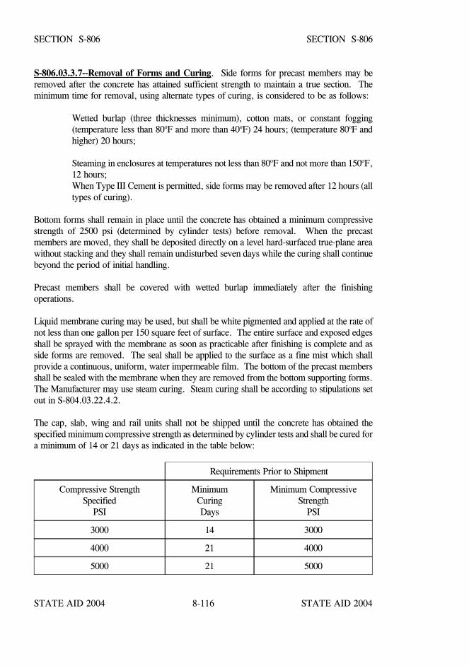
STATE AID 2004 STATE AID 2004
STATE AID 2004 STATE AID 20048-116
SECTION S-806 SECTION S-806
S-806.03.3.7--Removal of Forms and Curing. Side forms for precast members may beremoved after the concrete has attained sufficient strength to maintain a true section. Theminimum time for removal, using alternate types of curing, is considered to be as follows:
Wetted burlap (three thicknesses minimum), cotton mats, or constant fogging(temperature less than 80oF and more than 40oF) 24 hours; (temperature 80oF andhigher) 20 hours;
Steaming in enclosures at temperatures not less than 80oF and not more than 150oF,12 hours; When Type III Cement is permitted, side forms may be removed after 12 hours (alltypes of curing).
Bottom forms shall remain in place until the concrete has obtained a minimum compressivestrength of 2500 psi (determined by cylinder tests) before removal. When the precastmembers are moved, they shall be deposited directly on a level hard-surfaced true-plane areawithout stacking and they shall remain undisturbed seven days while the curing shall continuebeyond the period of initial handling.
Precast members shall be covered with wetted burlap immediately after the finishingoperations.
Liquid membrane curing may be used, but shall be white pigmented and applied at the rate ofnot less than one gallon per 150 square feet of surface. The entire surface and exposed edgesshall be sprayed with the membrane as soon as practicable after finishing is complete and asside forms are removed. The seal shall be applied to the surface as a fine mist which shallprovide a continuous, uniform, water impermeable film. The bottom of the precast membersshall be sealed with the membrane when they are removed from the bottom supporting forms.The Manufacturer may use steam curing. Steam curing shall be according to stipulations setout in S-804.03.22.4.2.
The cap, slab, wing and rail units shall not be shipped until the concrete has obtained thespecified minimum compressive strength as determined by cylinder tests and shall be cured fora minimum of 14 or 21 days as indicated in the table below:
Requirements Prior to Shipment
Compressive StrengthSpecified
PSI
MinimumCuringDays
Minimum CompressiveStrength
PSI
3000 14 3000
4000 21 4000
5000 21 5000
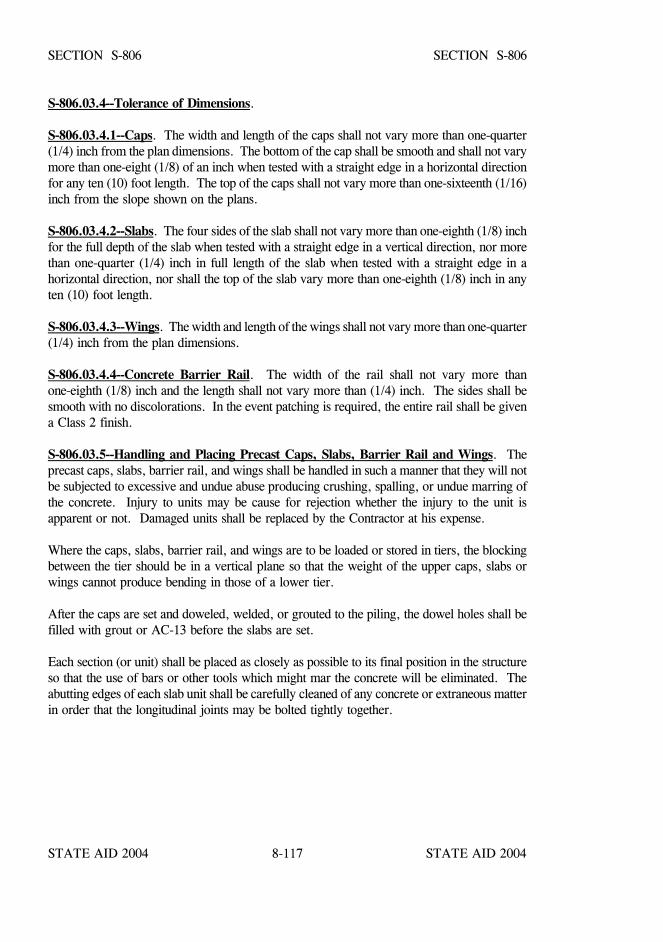
STATE AID 2004 STATE AID 2004
STATE AID 2004 STATE AID 20048-117
SECTION S-806 SECTION S-806
S-806.03.4--Tolerance of Dimensions.
S-806.03.4.1--Caps. The width and length of the caps shall not vary more than one-quarter(1/4) inch from the plan dimensions. The bottom of the cap shall be smooth and shall not varymore than one-eight (1/8) of an inch when tested with a straight edge in a horizontal directionfor any ten (10) foot length. The top of the caps shall not vary more than one-sixteenth (1/16)inch from the slope shown on the plans.
S-806.03.4.2--Slabs. The four sides of the slab shall not vary more than one-eighth (1/8) inchfor the full depth of the slab when tested with a straight edge in a vertical direction, nor morethan one-quarter (1/4) inch in full length of the slab when tested with a straight edge in ahorizontal direction, nor shall the top of the slab vary more than one-eighth (1/8) inch in anyten (10) foot length.
S-806.03.4.3--Wings. The width and length of the wings shall not vary more than one-quarter(1/4) inch from the plan dimensions.
S-806.03.4.4--Concrete Barrier Rail. The width of the rail shall not vary more thanone-eighth (1/8) inch and the length shall not vary more than (1/4) inch. The sides shall besmooth with no discolorations. In the event patching is required, the entire rail shall be givena Class 2 finish.
S-806.03.5--Handling and Placing Precast Caps, Slabs, Barrier Rail and Wings. Theprecast caps, slabs, barrier rail, and wings shall be handled in such a manner that they will notbe subjected to excessive and undue abuse producing crushing, spalling, or undue marring ofthe concrete. Injury to units may be cause for rejection whether the injury to the unit isapparent or not. Damaged units shall be replaced by the Contractor at his expense.
Where the caps, slabs, barrier rail, and wings are to be loaded or stored in tiers, the blockingbetween the tier should be in a vertical plane so that the weight of the upper caps, slabs orwings cannot produce bending in those of a lower tier.
After the caps are set and doweled, welded, or grouted to the piling, the dowel holes shall befilled with grout or AC-13 before the slabs are set.
Each section (or unit) shall be placed as closely as possible to its final position in the structureso that the use of bars or other tools which might mar the concrete will be eliminated. Theabutting edges of each slab unit shall be carefully cleaned of any concrete or extraneous matterin order that the longitudinal joints may be bolted tightly together.

STATE AID 2004 STATE AID 2004
STATE AID 2004 STATE AID 20048-118
SECTION S-806 SECTION S-806
When the abutment span is not a thirty-one foot (31') span and the total number of spans in thebridge is four or less, the Contractor shall set in place all precast units from the ground. TheContractor will be expected to drive piling and set units from the ground for the first two spansfrom each abutment, provided that the abutment span is a nineteen foot (19') span. When thebridge consists of a thirty-one foot (31') abutment span, or at any other time the Engineer hasdetermined that it is not feasible or possible to construct any additional spans from the ground,then he may permit construction to continue with equipment on the bridge deck subject to thefollowing:
(1) Contractor will set in place all span units; install and tighten all bolts; grout;wait for a period of at least seventy-two (72) hours after grouting; and, iftrack/crawler type crane is used, place appropriate construction mats on thedeck before putting crane on bridge.
(2) Construction mats for use with track/crawler type cranes shall be made oftimber with sufficient dimensions to prevent contact between the track andconcrete surface and to prevent undue marring of concrete slab.
(3) If pneumatic tire type crane is used, then it MUST be equipped withoutriggers. Outriggers ARE NOT to be set directly on precast concreteslabs. They are to be set on timber mats with minimum dimensions of 5'X 5' - 6" thick.
(4) After driving piling, the Contractor will set span units, install and tighten allbolts, grout and wait a minimum of seventy-two (72) hours before movingcrane onto next span.
(5) The seventy-two (72) hours minimum time period for placing equipment onbridge may be reduced to twelve (12) hours if approval is given toContractor by the Bridge Engineer to use an epoxy grout. If a non-shrinkcommercial type grout is used, it may be reduced to twenty-four (24) hours.
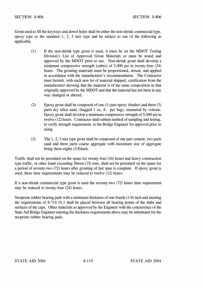
STATE AID 2004 STATE AID 2004
STATE AID 2004 STATE AID 20048-119
SECTION S-806 SECTION S-806
Grout used to fill the keyways and dowel holes shall be either the non-shrink commercial type,epoxy type or the standard 1, 2, 3 mix type and be subject to one of the following asapplicable.
(1) If the non-shrink type grout is used, it must be on the MDOT TestingDivision's List of Approved Grout Materials or must be tested andapproved by the MDOT prior to use. Non-shrink grout shall develop aminimum compressive strength (cubes) of 3,000 psi in twenty-four (24)hours. The grouting materials must be proportioned, mixed, and appliedin accordance with the manufacturer's recommendation. The Contractormust furnish, with each new lot of material shipped, certification from themanufacturer showing that the material is of the same composition as thatoriginally approved by the MDOT and that the material has not been in anyway changed or altered.
(2) Epoxy grout shall be composed of one (1) part epoxy (binder) and three (3)parts dry silica sand, (bagged 1 cu. ft. per bag), measured by volume.Epoxy grout shall develop a minimum compressive strength of 5,000 psi intwelve (12) hours. Contractor shall submit method of sampling and testing,to verify strength requirement, to the Bridge Engineer for approval prior tousing.
(3) The 1, 2, 3 mix type grout shall be composed of one part cement, two partssand and three parts coarse aggregate with maximum size of aggregatebeing three-eights (3/8)inch.
Traffic shall not be permitted on the spans for twenty-four (24) hours and heavy constructiontype traffic, or other loads exceeding fifteen (15) tons, shall not be permitted on the spans fora period of seventy-two (72) hours after grouting of last span is complete. If epoxy grout isused, these time requirements may be reduced to twelve (12) hours.
If a non-shrink commercial type grout is used the seventy-two (72) hours time requirementmay be reduced to twenty-four (24) hours.
Neoprene rubber bearing pads with a minimum thickness of one-fourth (1/4) inch and meetingthe requirements of S-714.10.1 shall be placed between all bearing points of the slabs andsurfaces of the caps. Other materials as approved by the Engineer with the concurrence of theState Aid Bridge Engineer meeting the thickness requirements above may be substituted for theneoprene rubber bearing pads.

STATE AID 2004 STATE AID 2004
STATE AID 2004 STATE AID 20048-120
SECTION S-806 SECTION S-806
S-806.03.5.1--Transverse Joints. When the completed bridge is to consist of more than onespan, there shall be placed in the joint between spans a bituminous premolded joint fillerone-quarter (1/4) inch in thickness. This joint filler shall be for the full thickness of theconcrete (less one inch at the top of the slab) and for the full width of the structure, includingthe curb. When the spans are completely in place and bolted the transverse joints shall besealed with AC-13 or other joint sealer approved by the Engineer.
S-806.03.5.2--Railing. The bridge railing shall be installed after all other work on the bridgehas been completed.
The material used shall meet the dimensions and requirements specified on the plans and therailing shall be constructed in conformity with the details indicated and to the lines and gradesestablished.
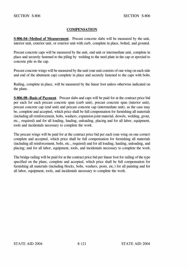
STATE AID 2004 STATE AID 2004
STATE AID 2004 STATE AID 20048-121
SECTION S-806 SECTION S-806
COMPENSATION
S-806.04--Method of Measurement. Precast concrete slabs will be measured by the unit,interior unit, exterior unit, or exterior unit with curb, complete in place, bolted, and grouted.
Precast concrete caps will be measured by the unit, end unit or intermediate unit, complete inplace and securely fastened to the piling by welding to the steel plate in the cap or epoxied toconcrete pile in the cap.
Precast concrete wings will be measured by the unit (one unit consists of one wing on each sideand end of the abutment cap) complete in place and securely fastened to the caps with bolts.
Railing, complete in place, will be measured by the linear foot unless otherwise indicated onthe plans.
S-806.08--Basis of Payment. Precast slabs and caps will be paid for at the contract price bidper each for each precast concrete span (curb unit), precast concrete span (interior unit),precast concrete cap (end unit) and precast concrete cap (intermediate unit), as the case maybe, complete and accepted, which price shall be full compensation for furnishing all materials(including all reinforcement, bolts, washers, expansion joint material, dowels, welding, grout,etc., required) and for all loading, hauling, unloading, placing and for all labor, equipment,tools and incidentals necessary to complete the work.
The precast wings will be paid for at the contract price bid per each (one wing on one corner)complete and accepted, which price shall be full compensation for furnishing all materials(including all reinforcement, bolts, etc., required) and for all loading, hauling, unloading, andplacing; and for all labor, equipment, tools, and incidentals necessary to complete the work.
The bridge railing will be paid for at the contract price bid per linear foot for railing of the typespecified on the plans, complete and accepted, which price shall be full compensation forfurnishing all materials (including blocks, bolts, washers, posts, etc.) for all painting and forall labor, equipment, tools, and incidentals necessary to complete the work.
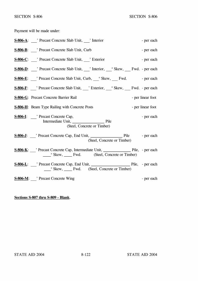
STATE AID 2004 STATE AID 2004
STATE AID 2004 STATE AID 20048-122
SECTION S-806 SECTION S-806
Payment will be made under:
S-806-A: ___’ Precast Concrete Slab Unit, ___’ Interior - per each
S-806-B: ___’ Precast Concrete Slab Unit, Curb - per each
S-806-C: ___’ Precast Concrete Slab Unit, ___’ Exterior - per each
S-806-D: ___’ Precast Concrete Slab Unit, ___’ Interior, ___o Skew, ___ Fwd. - per each
S-806-E: ___’ Precast Concrete Slab Unit, Curb, ___o Skew, ___ Fwd. - per each
S-806-F: ___’ Precast Concrete Slab Unit, ___’ Exterior, ___o Skew, ___ Fwd. - per each
S-806-G: Precast Concrete Barrier Rail - per linear foot
S-806-H: Beam Type Railing with Concrete Posts - per linear foot
S-806-I: ___’ Precast Concrete Cap, - per eachIntermediate Unit, Pile (Steel, Concrete or Timber)
S-806-J: ___’ Precast Concrete Cap, End Unit, Pile - per each (Steel, Concrete or Timber)
S-806-K: ___’ Precast Concrete Cap, Intermediate Unit, Pile, - per each o Skew, Fwd. (Steel, Concrete or Timber)
S-806-L: ___’ Precast Concrete Cap, End Unit, Pile, - per each o Skew, Fwd. (Steel, Concrete or Timber)
S-806-M: ___’ Precast Concrete Wing - per each
Sections S-807 thru S-809 - Blank.
STATE AID 2004 STATE AID 2004
STATE AID 2004 STATE AID 20048-123
SECTION S-810 - STEEL STRUCTURES
S-810.01--Description. This work shall consist of furnishing, fabricating, preparing,assembling, erecting, and painting structural steel and all accessories and other metal partsrequired in steel spans. This work shall be constructed as indicated on the plans, in reasonablyclose conformity with the lines, grades, dimensions, and design shown, and in accordance withthe applicable provisions and requirements in other sections of these specifications for thedifferent items which constitute the complete structure.
These specifications apply to bolted and welded construction.
FABRICATION
S-810.02--Materials.
S-810.02.1--General. Unless otherwise specified, structural steel, miscellaneous metals, andpaints shall conform to the applicable requirements of this section and S-710, S-716, S-717 andS-814. Unless otherwise specified, structural carbon steel shall be per ASTM Designation: A36.
S-810.02.2--Drawings. The Contractor shall prepare shop drawings for all materials to befabricated. The size of the sheets (36"x24") on which the drawings are prepared shall conformto the standard bridge sheet of the Office of State Aid Road Construction. Two complete setsof prints shall be submitted to the Engineer for approval, with concurrence of the State AidBridge Engineer, prior to ordering any materials for fabrication.
For all fabrication to be done by welding, two copies of welding procedures in accordance withthe provisions of ANSI/AASHTO/AWS D1.5 Bridge Welding Code, hereinafter referred toas the Welding Code, shall also be submitted to the Engineer for approval with concurrenceof the State Aid Bridge Engineer. After final approval of the shop drawings and weldingprocedures, if applicable, two complete sets of prints shall be submitted to the Engineer. Asrequired by special conditions, the Engineer shall be furnished with as many additional sets ofprints as may be necessary. Shop drawings for railroad bridges shall be prepared with ink onlinen tracing cloth or other approved equal, which shall be delivered to the Engineer prior tofinal acceptance of the project. No changes shall be made in a shop drawing after it has beenapproved, nor shall steel sections different from those shown on the plans be substituted exceptwith the written consent or direction of the Engineer.
Prior to the fabrication of any part of a structure, shop drawings and welding procedures forthat part of the structure shall have been given final, unconditional, approval by the Engineerwith concurrence of the State Aid Bridge Engineer. Work performed prior to approval ofdrawing and procedures may be rejected.
STATE AID 2004 STATE AID 2004
STATE AID 2004 STATE AID 20048-124
SECTION S-810 SECTION S-810
S-810.02.3--Shop Painting. Shop painting, unless otherwise designated or permitted, shallconsist of inorganic zinc primer, S-710, applied as specified in S-814. Machine finishedsurfaces of pins, pin rollers and bores shall be coated as soon as practicable after acceptancewith a heavy coat of Petrolatum meeting the requirements of ASTM Designation: D 217,NLGI Consistency grade 2 or 3 or other approved coating prior to removal from the shop.
S-810.02.4--Storage of Materials. Structural material, either plain or fabricated, shall bestored at the bridge shop above ground on platforms, skids, or other supports. It shall be keptfree from dirt, grease, and other foreign matter and shall be protected as far as practicablefrom corrosion.
S-810.02.5--Straightening Material. Rolled material, before being laid off or worked, mustbe straight. If straightening is necessary, it shall be done by methods that will not injure themetal. Heat straightening of ASTM Designation: A514/A517 steel shall be done only underrigidly controlled procedures and each application subject to the approval of the Engineer. Inno case shall the maximum temperature of the steel exceed 1125oF. Sharp kinks and bendswill be cause for rejection of the material.
S-810.02.6--Curving Rolled Beams and Welded Girders. Steels that are manufactured toa yield point greater than 50,000 psi shall not be heat curved.
S-810.02.6.1--Type of Heating. Beams and girders may be curved by either continuous orV-type heating as approved by the Engineer. For the continuous method, a strip along theedge of the top and bottom flange shall be heated simultaneously; the strip shall be of sufficientwidth and temperature to obtain the required curvature. For the V-type heating, the top andbottom flanges shall be heated in truncated triangular or wedge-shaped areas having their basesalong the flange edge and spaced at regular intervals along each flange; the spacing andtemperature shall be as required to obtain the required curvature, and heating shall progressalong the top and bottom flange at approximately the same rate.
For the V-type heating, the apex of the truncated triangular area applied to the inside flangesurface shall terminate just before the juncture of the web and the flange is reached. To avoidunnecessary web distortion, special care shall be taken when heating the inside flange surfaceso the heat is not applied directly to the web. When the radius of curvature is 1000 feet ormore, the apex of the truncated triangular heating pattern applied to the outside flange surfaceshall extend to the juncture of the flange and web. When the radius of curvature is less than1000 feet, the apex of the truncated triangular heating pattern applied to the outside flangesurface shall extend past the web for a distance equal to 1/8 of the flange or 3 inches, which-ever is less. The truncated triangular pattern shall have an included angle of approximately 15to 30 degrees, but the base of the triangle shall not exceed 10 inches. Variations in the patternsprescribed above may be made with the approval of the Engineer.
STATE AID 2004 STATE AID 2004
STATE AID 2004 STATE AID 20048-125
SECTION S-810 SECTION S-810
For both types of heating, the flange edges to be heated are those that will be on the inside ofthe horizontal curve after cooling. Heating both inside and outside flange surfaces is onlymandatory when the flange thickness is 1 1/4 inches or greater; in which case, the two surfacesshall be heated concurrently. The maximum temperature shall be as prescribed below.
S-810.02.6.2--Temperature. The heat-curving operation shall be conducted in such a mannerthat the temperature of the steel does not exceed 1150oF as measured by temperature indicatingcrayons or other suitable means. The girder shall not be artificially cooled until after naturallycooling to 600oF. The method of artificial cooling is subject to the approval of the Engineer.
S-810.02.6.3--Position for Heating. The girder may be heat-curved with the web in eithera vertical or a horizontal position. When curved in the vertical position, the girder shall bebraced or supported in such a manner that the tendency of the girder to deflect laterally duringthe heat-curving process will not cause the girder to overturn.
When curved in the horizontal position, the girder must be supported near its ends and atintermediate points, if required, to obtain a uniform curvature; the bending stress in the flangesdue to the dead weight of the girder must not exceed the usual allowable design stress. Whenthe girder is positioned horizontally for heating, intermediate safety catch blocks must bemaintained at the mid-length of the girder within two inches of the flanges at all times duringthe heating process to guard against a sudden sag due to plastic flange buckling.
S-810.02.6.4--Sequence of Operations. The girder shall be heat curved in the fabricationshop before it is painted. The heat curving operation may be conducted either before or afterall the required welding of transverse intermediate stiffeners is completed. However, unlessprovisions are made for girder shrinkage, connection plates and bearing stiffeners shall belocated and attached after heat curving. If longitudinal stiffeners are required, they shall beheat curved or oxygen cut separately and then welded to the curved girder. When cover platesare to be attached to rolled beams, they may be attached before heat curving if the totalthickness of one flange and cover plate is less than 2 ½ inches and the radius of curvature isgreater than 1000 feet. For other rolled beams with cover plates, the beams must beheat-curved before the cover plates are attached; cover plates must be either heat-curved oroxygen cut separately and then welded to the curved beam.
S-810.02.6.5--Camber. Girders shall be cambered before heat curving. Camber for rolledbeams may be obtained by heat-cambering methods approved by the Engineer. For plate gir-ders, the web shall be cut to the prescribed camber with suitable allowance for shrinkage dueto cutting, welding, and heat curving. The heat-curving process may tend to change thecervical camber present before heating. This effect will be most pronounced when the top andbottom flanges are of unequal widths on a given transverse cross section. However, subjectto the approval of the Engineer, moderate deviations from specified camber may be correctedby a carefully supervised application of heat.
STATE AID 2004 STATE AID 2004
STATE AID 2004 STATE AID 20048-126
SECTION S-810 SECTION S-810
S-810.02.6.6--Measurement of Curvature and Camber. Horizontal curvature and verticalcamber shall not be measured for final acceptance before all welding and heating operationsare completed, and the flanges have cooled to a uniform temperature. Horizontal curvatureshall be checked with the girder in the vertical position by measuring off-sets from a string lineor wire attached to both flanges or by using other suitable means. Camber shall be checkedby adequate means.
S-810.02.7--Finish. Portions of work exposed to view shall be finished neatly. Shearing,flame cutting, and chipping shall be done carefully and accurately.
S-810.02.8--Bolt Holes. All holes for bolts shall be either punched or drilled. Materialforming parts of a member composed of not more than five thicknesses of metal may bepunched 1/16 inch larger than the nominal diameter of the bolts whenever the thickness of themetal is not greater than 3/4 inch for structural steel, 5/8 inch for high strength steel, or ½ inchfor quenched and tempered alloy steel, unless subpunching and reaming is required underS-810.02.11.1.
When there are more than five thicknesses or when any of the main material is thicker than 3/4inch for structural steel, 5/8 inch for high strength steel, or 1/2 inch for quenched andtempered alloy steel, all holes shall either be subdrilled or drilled full size.
When required under S-810.02.11, all holes shall be either subpunched or subdrilled 3/16 inchsmaller and after assembling, reamed 1/16 inch larger or drilled full size to 1/16 inch largerthan the nominal diameter of bolts. Hole shall be subdrilled if thickness limitation governs.
S-810.02.9--Punched Holes. The diameter of the die shall not exceed the diameter of thepunch by more than 1/16 inch. If any holes must be enlarged to admit the bolts, such holesshall be reamed. Holes must be clean cut without torn or ragged edges. Poor matching ofholes will be cause for rejection.
S-810.02.10--Reamed or Drilled Holes. Reamed or drilled holes shall be cylindrical,perpendicular to the member, and shall comply with the requirements of S-810.02.8 as to size.Where practicable, reamers shall be directed by mechanical means. Burrs on the outsidesurfaces shall be removed. Poor matching of holes will be cause for rejection. Reaming anddrilling shall be done with twist drills. If required by the Engineer, assembled parts shall betaken apart for removal of burrs caused by drilling. Connecting parts requiring reamed ordrilled holes shall be assembled and securely held while being reamed or drilled and shall bematch marked before disassembling.
STATE AID 2004 STATE AID 2004
STATE AID 2004 STATE AID 20048-127
SECTION S-810 SECTION S-810
S-810.02.11--Preparation of Field Connections.
S-810.02.11.1--Sub-punching and Reaming of Field Connections. Unless otherwisespecified, holes in all field connections and field splices of main members of trusses, arches,continuous beam spans, bents, towers (each face), plate girders, and rigid frames shall besub-punched (or drilled if sub-drilling is required by S-810.02.8), and subsequently reamedwhile assembled or to a steel template, as required by S-810.02.16.
All holes for floorbeam and stringer field end connections shall be subpunched and reamed toa steel template or reamed while assembled.
Reaming or drilling full size of field connection holes through a steel template shall be doneafter the template has been located with utmost care as to position and angle and firmly boltedin place. Templates used for reaming matching members, or the opposite faces of a singlemember, shall be exact duplicates. Templates used for connections on like parts or membersshall be accurately located so that the parts or members are duplicates and require nomatch-marking.
For any connection, in lieu of subpunching and reaming or subdrilling and reaming, thefabricator may, at his option, drill holes full size with all thicknesses of material assembled inproper position.
If additional subpunching and reaming is required, it shall be as specified on the plans.
S-810.02.11.2--Numerically-Controlled Drilled Field Connections. Alternately, for anyconnection or splice designated in S-810.02.11.1, in lieu of sub-sized holes and reaming whileassembled, or drilling holes full-size while assembled, the Contractor shall have the option todrill bolt holes full-size in unassembled pieces and/or connections including templates for usewith matching sub-sized and reamed holes by means of suitable numerically-controlled (N/C)drilling equipment subject to the specific provisions contained in this article.
If N/C drilling equipment is used, the Engineer, unless otherwise stated in the specialprovisions or on the plans, may require the Contractor, by means of check assemblies, todemonstrate that this drilling procedure consistently produces holes and connections meetingthe requirements of S-810.02.13 and S-810.02.16.
STATE AID 2004 STATE AID 2004
STATE AID 2004 STATE AID 20048-128
SECTION S-810 SECTION S-810
The Contractor shall submit to the Engineer for approval with concurrence of the State AidBridge Engineer a detailed outline of the procedures that he proposes to follow inaccomplishing the work from initial drilling through check assembly, and, if required, toinclude the specific members of the structure that may be N/C drilled, the sizes of the holes,the location of common index and other reference points, composition of check assemblies, andall other pertinent information.
Holes drilled by N/C drilling equipment shall be drilled to appropriate size either throughindividual pieces or any combination of pieces held tightly together.
S-810.02.12--Accuracy of Punched and Drilled Holes. All holes punched full size,subpunched, or subdrilled shall be so accurately punched that after assembling (before anyreaming is done) a cylindrical pin 1/8 inch smaller in diameter than the nominal size of thepunched hole may be entered perpendicular to the face of the member, without drifting, in atleast 75 percent of the contiguous holes in the same plane. If this requirement is not fulfilled,the badly punched pieces will be rejected. If any hole will not pass a pin 3/16 inch smaller indiameter than the nominal size of the punched hole, this will be cause for rejection.
S-810.02.13--Accuracy of Reamed and Drilled Holes. When holes are reamed or drilled,85 percent of the holes in any contiguous group shall, after reaming or drilling, show no offsetgreater than 1/32 inch between adjacent thicknesses of metal.
All steel templates shall have hardened steel bushings in holes accurately dimensioned from thecenter lines of the connection as inscribed on the template. The center lines shall be used inaccurately locating the template from the milled or scribed ends of the members.
S-810.02.14--Fitting for Bolting. Surfaces of metal in contact shall be cleaned beforeassembling. The parts of a member shall be assembled, well pinned, and firmly drawntogether with bolts before reaming is commenced. Assembled pieces shall be taken apart, ifnecessary, for the removal of burrs and shavings produced by the reaming operation. Themember shall be free from twists, bends, and other deformation.
End connection angles, stiffener angles, and similar parts shall be carefully adjusted to correctposition and bolted, clamped, or otherwise firmly held in place until riveted.
Parts in the shop shall be secured by bolts, insofar as practicable, to prevent damage inshipment and handling.
STATE AID 2004 STATE AID 2004
STATE AID 2004 STATE AID 20048-129
SECTION S-810 SECTION S-810
S-810.02.15—Blank.
S-810.02.16--Shop Assembling.
S-810.02.16.1-General. The field connections of main members of trusses, arches,continuous beam spans, bents, towers (each face), plate girders, and rigid frames shall beassembled in the shop with milled ends of compression members in full bearing, and then shallhave their sub-size holes reamed to specified size while the connections are assembled.
Assembly shall be Full Truss or Girder Assembly unless Progressive Truss or GirderAssembly, Full Chord Assembly, Progressive Chord Assembly, or Special Complete StructureAssembly is specified in the special provisions or on the plans. Modifications to theseassemblies may be allowed when approved in writing by the Engineer with concurrence of theState Aid Bridge Engineer.
When required on the plans, check assemblies and N/C drilled field connections shall be inaccordance with the provisions of S-810.02.16.7.
Each assembly, including camber, alignment, accuracy of holes, and fit of milled joints, shallbe approved by the Engineer, with concurrence of the State Aid Bridge Engineer, beforereaming is commenced or before an N/C drilled check assembly is dismantled.
A camber diagram shall be furnished the Engineer by the Fabricator showing the camber ateach panel point of each truss, arch rib, continuous beam line, plate girder, or rigid frame. Fraction points of span lengths shall be 1/4 points minimum, 1/10 points maximum. Whenthe shop assembly is full truss or girder assembly or special complete structure assembly, thecamber diagram shall show the camber measured in assembly. When any of the other methodsof shop assembly is used, the camber diagram shall show calculated camber.
S-810.02.16.2--Full Truss or Girder Assembly. Full truss or girder assembly shall consistof assembling all members of each truss, arch rib, bent, tower face, continuous beam line,plate girder, or rigid frame at one time.
S-810.02.16.3--Progressive Truss or Girder Assembly. Progressive truss or girderassembly shall consist of assembling initially for each truss, arch rib, bent, tower face,continuous beam line, plate girder, or rigid frame at least three contiguous shop sections or allmembers in at least three contiguous panels but not less than the number of panels associatedwith three contiguous chord lengths (i.e., length between field splices) and not less than 150feet in the case of structures longer than 150 feet. At least one shop section or panel or asmany panels as are associated with a chord length shall be added at the advancing end of theassembly before any member is removed from the rearward end, so that the assembled portionof the structure is never less than that specified above.
STATE AID 2004 STATE AID 2004
STATE AID 2004 STATE AID 20048-130
SECTION S-810 SECTION S-810
S-810.02.16.4--Full Chord Assembly. Full chord assembly shall consist of assembling, withgeometric angles at the joints, the full length of each chord of each truss or open spandrel arch,or each leg of each bent or tower, then reaming their field connection holes while the membersare assembled and reaming the web member connection to steel templates set at geometric (notcambered) angular relation to the chord lines.
Field connection holes in web members shall be reamed to steel templates. At least one endof each web member shall be milled or shall be scribed normal to the longitudinal axis of themember and the templates at both ends of the member shall be accurately located from one ofthe milled end or scribed lines.
S-810.02.16.5--Progressive Chord Assembly. Progressive chord assembly shall consist ofassembling contiguous chord members in the manner specified for full chord assembly and inthe number and length specified for progressive truss or girder assembly.
S-810.02.16.6--Special Complete Structure Assembly. Special complete structure assemblyshall consist of assembling the entire structure, including the floor system. This procedure isordinarily needed only for complicated structures such as those having curved girders, orextreme skew in combination with severe grade or camber, and will be required only when soindicated on the plans.
S-810.02.16.7--Check Assemblies with Numerically Controlled Drilled Field Connections.When required, a check assembly shall be fabricated for each major structural type and shallconsist of at least three contiguous shop sections or, in a truss, all members in at least threecontiguous panels but not less than the number of panels associated with three contiguouschord lengths (i.e., length between field splices). Check assemblies should be based on theproposed order of erection, joints in bearings, special complex points, and similarconsiderations. Such special points could be the portals of skewed trusses, etc.
Use of either geometric angles (giving theoretically zero secondary stresses under dead-loadconditions after erection) or cambered angles (giving theoretically zero secondary stressesunder no-load conditions) should be designated on the plans or in the special provisions.
The check assemblies shall preferably be the first such section of each major structural type tobe fabricated.
No match-marking and no shop assemblies other than the check assemblies will be required.
If the check assembly fails in some specific manner to demonstrate that the required accuracyis being obtained, further check assemblies may be required by the Engineer for which thereshall be no additional cost to the Project.
STATE AID 2004 STATE AID 2004
STATE AID 2004 STATE AID 20048-131
SECTION S-810 SECTION S-810
S-810.02.17--Drifting of Holes. The drifting done during assembling shall be only such asto bring the parts into position and not sufficient to enlarge the holes or distort the metal. Ifany holes must be enlarged to admit the bolts, they shall be reamed.
S-810.02.18--Match-Marking. Connecting parts assembled in the shop for the purpose ofreaming holes in field connections shall be match-marked, and a diagram showing such marksshall be furnished to the Engineer.
S-810.02.19--Blank.
S-810.02.20--Bolts and Bolted Connections. Bolted connections fabricated with high strengthbolts shall conform to S-810.02.21.
S-810.02.20.1--General. Bolts shall be unfinished, turned, or ribbed bolts conforming to therequirements for Grade A Bolts or Specification for Low-Carbon Steel Externally andInternally Threaded Standard Fasteners, ASTM Designation: A 307. Bolted connections shallbe used only as indicated by the plans or special provisions. Bolts shall have single self-lockingnuts or double nuts unless otherwise shown on the plans or in the special provisions. Beveledwashers shall be used where bearing faces have a slope of more than 1:20 with respect to aplane normal to the bolt axis.
S-810.02.20.2--Unfinished Bolts. Unfinished bolts shall be furnished unless other types arespecified.
S-810.02.20.3--Turned Bolts. The surface of the body of turned bolts shall meet the ANSIroughness rating value of 125. Heads and nuts shall be hexagonal with standard dimensionsfor bolts of the nominal size specified or the next larger nominal size. Diameter of threads shallbe equal to the body of the bolt or the nominal diameter of the bolt specified. Holes for turnedbolts shall be carefully reamed with bolts furnished to provide for light driving fit. Threadsshall be entirely outside of the holes. A washer shall be provided under the nut.
S-810.02.20.4--Ribbed Bolts. The body of ribbed bolts shall be of an approved form withcontinuous longitudinal ribs. The diameter of the body measured on a circle through the pointsof the ribs shall be 5/64 inch greater than the nominal diameter specified for the bolts.
Ribbed bolts shall be furnished with round heads conforming to ANSI B 18.5 unless otherwisespecified. Nuts shall be hexagonal, either recessed or with a washer of suitable thickness.Ribbed bolts shall make a driving fit with the holes. The hardness of the ribs shall be such thatthe ribs do not mash down enough to permit the bolts to turn in the holes during tightening.If for any reason the bolt twists before drawing tight, the hole shall be carefully reamed andan oversized bolt used as a replacement.

STATE AID 2004 STATE AID 2004
STATE AID 2004 STATE AID 20048-132
SECTION S-810 SECTION S-810
S-810.02.21--Connections Using High Strength Bolts. This subsection covers the assemblyof structural joints using ASTM Designation: A 325 high strength bolts for structural steeljoints or ASTM Designation: A 490 quenched and tempered alloy bolts for structural steeljoints, or equivalent fasteners, tightened to a high tension. The bolts are used in holesconforming to the requirements of S-810.02.8, S-810.02.9 and S-810.02.10.
S-810.02.21.1 --Bolts, Nuts, Washers and Direct Tension Indicators (DTI). All bolts, nuts,washers and DTI shall conform to the requirements of S-717 for such items.
Unless otherwise shown on the plans, all threaded bolts shall be of sufficient length to provideat least full-thread engagement, as defined in S-810.04.4, immediately prior to final tensioning.
All markings on bolts, nuts, washers and direct tension indicators must include the symbol ofthe Manufacturer and not the Distributor or any other trading entity. This is spelled out in allASTM specifications covering these product categories. A325 bolts shall be marked "A325"and A490 bolts marked "A490". Type 1 A325 bolts shall be marked with three radial lines120o apart. Type 3 A325 bolts shall have A325 underlined plus other distinguishing marksindicating that the bolt is atmospheric corrosion resistant and of a weathering type. Type 2A325 bolts shall be marked with three radial lines 60o apart. Direct tension indicators shallalso be marked "325" in the case of Type "325" or "490".
S-810.02.21.2--Bolted Parts. The slope of surfaces of bolted parts in contact with the bolthead and nut shall not exceed 1:20 with respect to a plane normal to the bolt axis. Bolted partsshall fit solidly together when assembled and shall not be separated by gaskets or any otherinterposed compressible material.
When assembled, all joint surfaces, including those adjacent to the bolt heads, nuts, orwashers, shall be free of scale, except tight mill scale, and shall also be free of dirt, loosescale, burrs, other foreign material, and other defects that would prevent solid seating of theparts. Paint is permitted in bearing-type connections.
Contact surfaces within friction-type joints shall be free of oil, paint, lacquer or other coatings,except as listed below:
A. Hot dip galvanizing, if contact surfaces are scored by wire brushing orblasting after galvanizing and prior to assembly. The wire brushingtreatment shall be a light application of manual brushing, not power wirebrushing, that marks or scores the surface but removes relatively little of thezinc coating. The blasting treatment shall be a light "brush-off" treatmentwhich will produce a dull gray appearance. However, neither treatmentshould be severe enough to produce any break or discontinuity in the zincsurface.
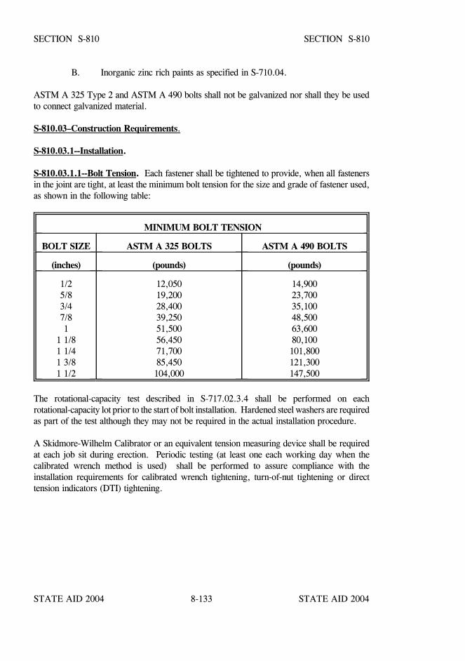
STATE AID 2004 STATE AID 2004
STATE AID 2004 STATE AID 20048-133
SECTION S-810 SECTION S-810
B. Inorganic zinc rich paints as specified in S-710.04.
ASTM A 325 Type 2 and ASTM A 490 bolts shall not be galvanized nor shall they be usedto connect galvanized material.
S-810.03–Construction Requirements.
S-810.03.1--Installation.
S-810.03.1.1--Bolt Tension. Each fastener shall be tightened to provide, when all fastenersin the joint are tight, at least the minimum bolt tension for the size and grade of fastener used,as shown in the following table:
MINIMUM BOLT TENSION
BOLT SIZE ASTM A 325 BOLTS ASTM A 490 BOLTS
(inches) (pounds) (pounds)
1/25/83/47/81
1 1/81 1/41 3/81 1/2
12,05019,20028,40039,25051,50056,45071,70085,450104,000
14,90023,70035,10048,50063,60080,100101,800121,300147,500
The rotational-capacity test described in S-717.02.3.4 shall be performed on eachrotational-capacity lot prior to the start of bolt installation. Hardened steel washers are requiredas part of the test although they may not be required in the actual installation procedure.
A Skidmore-Wilhelm Calibrator or an equivalent tension measuring device shall be requiredat each job sit during erection. Periodic testing (at least one each working day when thecalibrated wrench method is used) shall be performed to assure compliance with theinstallation requirements for calibrated wrench tightening, turn-of-nut tightening or directtension indicators (DTI) tightening.
STATE AID 2004 STATE AID 2004
STATE AID 2004 STATE AID 20048-134
SECTION S-810 SECTION S-810
The Contractor shall provide all wrenches necessary for obtaining the specified bolt tension,and shall also provide at his expense the necessary inspection wrenches and provisions forcalibration of such wrenches as specified in this subsection and in S-810.03.2.
Threaded bolts shall be checked for tension with properly calibrated wrenches, by theturn-of-nut method, or by the use of Direct Tension Indicators. When required because of boltentering and wrench operating clearances, tightening may be accomplished by turning the boltwhile the nut is prevented from rotating, provided the requirements of S-810.03.1.2 andS-810.03.1.5 are met.
Impact wrenches, if used, shall be of adequate capacity and sufficiently supplied with air toperform the required tightening of each bolt in approximately 10 seconds.
ASTM A490 and galvanized ASTM A325 bolts shall not be reused. Other ASTM A325 boltsmay be reused, but not more than once, if approved by the Engineer. Retightening previouslytightened bolts which may have been loosened by the tightening of adjacent bolts shall not beconsidered as a reuse.
Galvanized nuts shall be checked to verify that a visible lubricant is on the threads. Black boltsshall be "oily" to the touch when delivered and installed. Weathered or rusted bolts and nutsshall be cleaned and relubricated prior to installation. Bolt, nut and washer combinations asinstalled shall be from the same rotational-capacity lot, reference S-717.02.
S-810.03.1.2--Washers. All fasteners shall have a hardened washer under the element (nutor bolt head) turned in tightening except that ASTM A325 bolts installed by the turn of the nutmethod in holes which are not oversize or slotted may have the washer omitted. Hardenedwashers shall be used under both the head and nut regardless of the element turned in the caseof ASTM A490 bolts if the material against which it bears has a specified yield strength lessthan 40 ksi. When ASTM A 490 bolts over one inch in diameter are used in conjunction withshort slotted or oversized holes, the hardened washers shall be at least 5/16 inch thick.
Where an outer face of the bolted parts has a slope of more than 1:20 with respect to a planenormal to the bolt axis, a smooth beveled washer shall be used to compensate for the lack ofparallelism.
STATE AID 2004 STATE AID 2004
STATE AID 2004 STATE AID 20048-135
SECTION S-810 SECTION S-810
S-810.03.1.3--Calibrated Wrench Tightening. When calibrated wrenches are used toprovide the bolt tension specified in S-810.03.1.1, their setting shall be such as to induce a bolttension 5 percent to 10 percent in excess of this value. These wrenches shall be calibrated atleast once each working day by tightening, in a device capable of indicating actual bolt tension,not less than three typical bolts of each diameter to be installed. Power wrenches shall beadjusted to stall or cut-out at the selected tension. If manual force wrenches are used, the forceindication corresponding to the calibrating tension shall be noted and used in the installation ofall bolts of the tested lot. Nuts shall be in tightening motion when torque is measured. Whenusing calibrated wrenches to install several bolts in a single joint, the wrench shall be returnedto "touch up" bolts previously tightened, which may have been loosened by the tightening ofsubsequent bolts, until all are tightened to the specified tension.
The required torque for calibrated wrenches may be approximated by the following formula:T(inch-pounds) = 0.2 x Bolt Diameter (inches) x Bolt Tension (pounds)
S-810.03.1.4--Turn-of-Nut Tightening. When the turn-of-nut method is used to provide thebolt tension specified in S-810.03.1.1, there shall first be enough bolts brought to a "snugtight" condition to insure that the parts of the joint are brought into full contact with each other."Snug tight" is defined as the initial tightening of the nut such that a load in the bolt of not lessthan 10% of the specified proof load for each type and size bolt used is produced. Followingthis initial operation, bolts shall be placed in the remaining holes in the connection and broughtto snug tightness. All bolts in the joint shall then be tightened additionally by the applicablenut rotation specified in the following table with tightening progressing systematically from themost rigid part of the joint to its free edges. During this operation there shall be no rotationof the part not turned by the wrench.
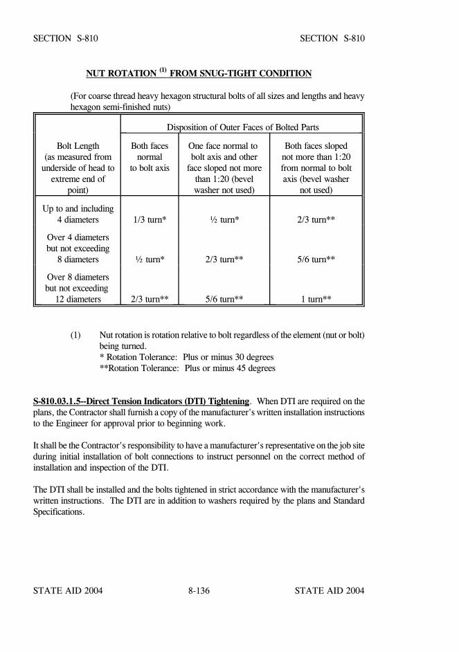
STATE AID 2004 STATE AID 2004
STATE AID 2004 STATE AID 20048-136
SECTION S-810 SECTION S-810
NUT ROTATION (1) FROM SNUG-TIGHT CONDITION
(For coarse thread heavy hexagon structural bolts of all sizes and lengths and heavyhexagon semi-finished nuts)
Disposition of Outer Faces of Bolted Parts
Bolt Length(as measured from
underside of head toextreme end of
point)
Both facesnormal
to bolt axis
One face normal to bolt axis and other
face sloped not morethan 1:20 (bevelwasher not used)
Both faces slopednot more than 1:20from normal to boltaxis (bevel washer
not used)
Up to and including4 diameters 1/3 turn* ½ turn* 2/3 turn**
Over 4 diametersbut not exceeding
8 diameters ½ turn* 2/3 turn** 5/6 turn**
Over 8 diametersbut not exceeding
12 diameters 2/3 turn** 5/6 turn** 1 turn**
(1) Nut rotation is rotation relative to bolt regardless of the element (nut or bolt)being turned.
* Rotation Tolerance: Plus or minus 30 degrees**Rotation Tolerance: Plus or minus 45 degrees
S-810.03.1.5--Direct Tension Indicators (DTI) Tightening. When DTI are required on theplans, the Contractor shall furnish a copy of the manufacturer's written installation instructionsto the Engineer for approval prior to beginning work.
It shall be the Contractor's responsibility to have a manufacturer's representative on the job siteduring initial installation of bolt connections to instruct personnel on the correct method ofinstallation and inspection of the DTI.
The DTI shall be installed and the bolts tightened in strict accordance with the manufacturer'swritten instructions. The DTI are in addition to washers required by the plans and StandardSpecifications.
STATE AID 2004 STATE AID 2004
STATE AID 2004 STATE AID 20048-137
SECTION S-810 SECTION S-810
DTI protrusions for all installations shall bear against a hardened unturned surface, normallyeither the underside of the bolt head or a hardened washer, and never directly against theturned element.
Prior to the final tightening of all high strength bolts, all the plies of steel shall be drawntogether by partially compressing DTI protrusions to ensure "snug tight" conditions. The finaltightening shall progress systematically from the most rigid part of the joint to its free edgesuntil the DTI on all bolts are closed to 0.005 inch.
DTI shall not be reused. If it becomes necessary to loosen a bolt previously tensioned, the DTIshall be discarded and replaced.
Bolts shall be of sufficient length to accommodate an indicator and washers made necessary byits use.
The Contractor shall furnish a Skidmore-Wilhelm device or approved equal capable ofmeasuring actual bolt tension. At least three typical bolts and direct tension indicators shall betightened in a device capable of determining their performance characteristics prior to the startof bolt placement. The device shall be made available thereafter during bolt placement forsimilar checks not to exceed intervals of one week unless directed otherwise by the Engineer.
High strength bolts, nuts, washers, and direct tension indicators shall be shipped to the projectsite in sealed metal containers or an approved equal. They shall be stored out of the weatherin a location approved by the Engineer. The containers shall remain unopened until thecontents are needed for erection. Bolts which, before use, have been exposed and becomedried out or rusty will be rejected and will not be used until they are cleaned and lubricated.
S-810.03.1.6--Lock-Pin and Collar Fasteners. The installation of lock-pin and collarfasteners shall be by methods and procedures approved by the Engineer.
STATE AID 2004 STATE AID 2004
STATE AID 2004 STATE AID 20048-138
SECTION S-810 SECTION S-810
S-810.03.2--Inspection. The Engineer will observe the installation and tightening of bolts todetermine that the selected tightening procedure is properly used and will determine that allbolts are tightened. When the calibrated wrench method of tightening is used, the Engineerwill have full opportunity to witness the calibration tests prescribed in S-810.03.1.3.
The following inspection shall be used unless a more extensive or different inspectionprocedure is specified.
S-810.03.2.1. Either the Engineer, or the Contractor in the presence of the Engineer, shalluse an inspecting wrench which may be either a torque wrench or a power wrench that can beaccurately adjusted in accordance with the requirements of S-810.03.1.3.
S-810.03.2.2 Three bolts of the same grade, size (length may be any length representativeof bolts used in the structure) and conditions as those under inspection shall be placedindividually in a calibration device capable of indicating bolt tension. There shall be a washerunder the part turned in tightening each bolt.
S-810.03.2.3. When the inspecting wrench is a torque wrench, each bolt specified inS-810.03.2.2 shall be tightened in the calibration device by any convenient means to theminimum tension specified for its size in S-810.03.1.1. The inspecting wrench then shall beapplied to the tightened bolt and the torque necessary to turn the nut or head five degrees(approximately one inch at 12 inch radius) in the tightening direction shall be determined. Theaverage torque measured in the tests of three bolts shall be taken as the job inspecting torqueto be used in the manner specified in S-810.03.2.5.
S-810.03.2.4. When the inspecting wrench is a torque wrench it shall be adjusted so that itwill tighten each bolt specified in S-810.03.2.2 to a tension at least 5 but not more than 10percent greater than the minimum tension specified for its size in S-810.03.1.1. This settingof wrench shall be taken as the job inspecting torque to be used in the manner specified in thefollowing paragraph.
S-810.03.2.5. Bolts represented by the sample prescribed in S-810.03.2.2 which have beentightened in the structure shall be inspected by applying, in the tightening direction, theinspecting wrench and its job inspecting torque to 10 percent of the bolts, but not less than twobolts, selected at random in each connection. If no nut or bolt head is turned by this appli-cation of the job inspecting torque, the connection shall be accepted as properly tightened. Ifany nut or bolt head is turned by the application of the job inspecting torque, this torque shallbe applied to all bolts in the connection, and all bolts whose nut or head is turned by the jobinspecting torque shall be tightened and re-inspected, or alternatively, the fabricator or erector,at no additional cost to the Project, may re-tighten all of the bolts in the connection in themanner required and subject to the limitations imposed for the initial tightening and thenresubmit the connection for the specified inspection.
STATE AID 2004 STATE AID 2004
STATE AID 2004 STATE AID 20048-139
SECTION S-810 SECTION S-810
S-810.03.2.6. When direct tension indicators are used, the Engineer’s inspector will check forcorrect tensioning by inserting a correct-thickness pointed feeler gage into the opening betweenadjacent flattened protrusions in accordance with the manufacturer's instructions andS-810.03.1.5. At least ten percent, but no less than two, of the bolts in each connection willbe examined.
A nil gap on ASTM A325 bolts is not cause for rejection. A nil gap for ASTM A490 boltsis not allowed.
S-810.03.2.7. The procedures for inspecting and testing the lock-pin and collar fasteners andtheir installation to insure that the required pre-load tension is provided shall be as approvedby the Engineer.
S-810.03.3--Blank.
S-810.03.4--Plate Cut Edges.
S-810.03.4.1--Edge Planing. Sheared edges of plates more than 5/8 inch in thickness andcarrying calculated stress shall be planed to a depth of 1/4 inch. Re-entrant cuts shall befilleted to a minimum radius of 3/4 inch before cutting.
S-810.03.4.2--Visual Inspection and Repair of Plate Cut Edges. Visual inspection andrepair of plate cut edges shall be in accordance with the Welding Code.
S-810.03.5--Welds. Welding of steel structures, when authorized on the plans or on approvedworking drawings, and pre-qualification of welding operators shall conform to the WeldingCode, current at the time of advertisement for bids.
Welding shall be tested by non-destructive methods as prescribed in the noted Welding Codeand as indicated on the plans. Edge blocks shall be used when radiographing butt weldsgreater than ½ inch thickness. The edge blocks shall have a length sufficient to extend beyondeach side of the weld centerline for a minimum distance equal to the weld thickness, but no lessthan 2 inches, and shall have a thickness equal to or greater than the thickness of the weld.The minimum width of the edge blocks shall be equal to half the weld thickness, but not lessthan 1 inch. The edge blocks shall be centered on the weld with a snug fit against the platebeing radiographed, allowing no more than 1/16 inch gap. Edge blocks shall be made ofradiographically clean steel and the surface shall have a finish of ANSI 125 µinch, orsmoother. Non-destructive testing shall be performed at the expense of the Contractor.
S-810.03.6--Oxygen Cutting. All oxygen cutting shall conform to the Welding Code.
STATE AID 2004 STATE AID 2004
STATE AID 2004 STATE AID 20048-140
SECTION S-810 SECTION S-810
S-810.03.7--Facing of Bearing Surfaces. The surface finish of bearing and base plates andother bearing surfaces that are to come in contact with each other or with concrete shall meetthe ANSI surface roughness requirements as defined in ANSI B 46.1, Surface Roughness,Waviness, and Lay, Part 1:
Steel Slabs ANSI 2,000Heavy plates in contact in shoes to be welded ANSI 1,000Milled ends and compression members, milled or ground ends of stiffeners, and fillers ANSI 500Bridge rollers and rockers ANSI 250Pins and pin holes ANSI 125Sliding bearings ANSI 125
S-810.03.8--Abutting Joints. Abutting joints in compression members and girder flanges,and in tension members where so specified on the drawings, shall be faced and brought to aneven bearing. Where joints are not faced, the opening shall not exceed 1/4 inch.
S-810.03.9--End Connection Angles. Floorbeams, stringers and girders having endconnection angles shall be built to the exact length shown on the plans measured between theheels of the connection angles, with a permissible tolerance of 0 inch to minus 1/16 inch.Where continuity is to be required, end connections shall be faced. The thickness of theconnection angles shall not be less than 3/8 inch or that shown on the detail drawings.
S-810.03.10--Lacing Bars. The ends of lacing bars shall be neatly rounded unless anotherform is required.
S-810.03.11--Fabrication of Members. Unless otherwise shown on the plans, steel plates formain members, not secondary members, shall be cut and fabricated so that the primarydirection of rolling is parallel to the direction of the main tensile and/or compressive stresses.
Fabricated members shall be true to line and free from twists, bends and open joints.
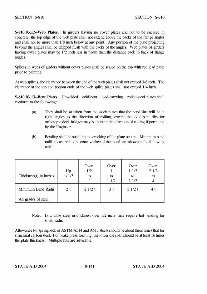
STATE AID 2004 STATE AID 2004
STATE AID 2004 STATE AID 20048-141
SECTION S-810 SECTION S-810
S-810.03.12--Web Plates. In girders having no cover plates and not to be encased inconcrete, the top edge of the web plate shall not extend above the backs of the flange anglesand shall not be more than 1/8 inch below at any point. Any portion of the plate projectingbeyond the angles shall be chipped flush with the backs of the angles. Web plates of girdershaving cover plates may be 1/2 inch less in width than the distance back to back of flangeangles.
Splices in webs of girders without cover plates shall be sealed on the top with red lead pasteprior to painting.
At web splices, the clearance between the end of the web plates shall not exceed 3/8 inch. Theclearance at the top and bottom ends of the web splice plates shall not exceed 1/4 inch.
S-810.03.13--Bent Plates. Unwelded, cold-bent, load-carrying, rolled-steel plates shallconform to the following:
(a) They shall be so taken from the stock plates that the bend line will be atright angles to the direction of rolling, except that cold-bent ribs fororthotopic deck bridges may be bent in the direction of rolling if permittedby the Engineer.
(b) Bending shall be such that no cracking of the plate occurs. Minimum bendradii, measured to the concave face of the metal, are shown in the followingtable:
Thickness(t) in inches
Upto 1/2
Over 1/2 to 1
Over1to
1 1/2
Over1 1/2
to2 1/2
Over 2 1/2
to4
Minimum Bend Radii All grades of steel
2 t 2 1/2 t 3 t 3 1/2 t 4 t
Note: Low alloy steel in thickness over 1/2 inch may require hot bending forsmall radii.
Allowance for springback of ASTM A514 and A517 steels should be about three times that forstructural carbon steel. For brake press forming, the lower die span should be at least 16 timesthe plate thickness. Multiple hits are advisable.
STATE AID 2004 STATE AID 2004
STATE AID 2004 STATE AID 20048-142
SECTION S-810 SECTION S-810
If a shorter radius is essential, the plates shall be bent hot at a temperature not greater than1200o F, except for ASTM A514/A517 steel. If ASTM A514/A517 steel plates to be bent areheated to a temperature greater than 1125oF, they must be requenched and tempered inaccordance with the producing mill's practice. Hot bent plates shall conform to requirement(a).
(c) Before bending, the corners of the plate shall be roundedto a radius of 1/16 inch throughout the portion of theplate at which the bending is to occur.
S-810.03.14--Fit of Stiffeners. End stiffeners of girders and stiffeners intended as supportsfor concentrated loads shall have full bearing (either milled, ground, or, on weldable steel incompression areas of flanges, welded as shown on the plans or specified) on the flanges towhich they transmit load or from which they receive load.
Stiffeners not intended to support concentrated loads shall, unless shown or specifiedotherwise, fit sufficiently tight to exclude water after being painted. Fillers under stiffenersshall fit within 1/4 inch at each end.
S-810.03.15--Eyebars. Pin holes may be flame cut at least two inches smaller in diameterthan the finished pin diameter. All eyebars that are to be placed side by side in the structureshall be securely fastened together in the order that they will be placed on the pin and boredat both ends while so clamped. Eyebars shall be packed and match marked for shipment anderection. All identifying marks shall be stamped with steel stencils on the edge of one head ofeach member after fabrication is completed so as to be visible when the bars are nested in placeon the structure. The eyebars shall be straight and free from twists and the pin holes shall beaccurately located on the centerline of the bar.
The inclination of any bar to the plane of the truss shall not exceed 1/16 inch to a foot. Theedges of eyebars that lie between the transverse centerline of their pin holes shall be cutsimultaneously with two mechanically operated torches abreast of each other, guided by a sub-stantial template, in such a manner as to prevent distortion of the plates.
S-810.03.16--Annealing and Stress Relieving. Structural members which are indicated to beannealed or normalized shall have finished machining, boring, and straightening donesubsequent to heat treatment. Normalizing and annealing (full annealing) shall be as specifiedin ASTM Designation: E 44. The temperatures shall be maintained uniformly throughout thefurnace during the heating and cooling so that the temperature at no two points on the memberwill differ by more than 100oF at any one time.

STATE AID 2004 STATE AID 2004
STATE AID 2004 STATE AID 20048-143
SECTION S-810 SECTION S-810
Members of ASTM A514/A517 steels shall not be annealed or normalized and shall be stressrelieved only with the approval of the Engineer.
A record of each furnace charge shall identify the pieces in the charge and show thetemperatures and schedule actually used.
Proper instruments, including recording pyrometers, shall be provided for determining at anytime the temperatures of members in the furnace. The records of the treatment operation shallbe available to and meet the approval of the Engineer. The holding temperature for stressrelieving ASTM A514/A517 steel shall not exceed 1125oF.
Members, such as bridge shoes, pedestals, or other parts which are built up by weldingsections of plate together shall be stress relieved in accordance with the procedure of theWelding Code.
S-810.03.17--Pins and Rollers. Pins and rollers shall be accurately turned to the dimensionsshown on the drawings and shall be straight, smooth, and free from flaws. Pins and rollersmore than nine inches in diameter shall be forged and annealed. Pins and rollers nine inchesor less in diameter may be either forged and annealed or cold-finished carbon-steel shafting.
In pins larger than nine inches in diameter, a hole not less than two inches in diameter shall bebored full length along the axis after the forging has been allowed to cool to a temperaturebelow the critical range under suitable conditions to prevent injury by too rapid cooling andbefore being annealed.
S-810.03.18--Boring Pin Holes. Pin holes shall be bored true to the specified diameter,smooth, and straight, at right angles with the axis of the member, and parallel with each otherunless otherwise required. The final surface shall be produced by a finishing cut.
The distance outside to outside of end holes in tension members and inside to inside of endholes in compression members shall not vary from that specified by more than 0.031 inch.Boring of holes in built-up members shall be done after the bolting is complete.
S-810.03.19--Pin Clearances. The diameter of the pin hole shall not exceed that of the pinby more than 0.020 inch for pins five inches or less in diameter or 0.031 inch for larger pins.
S-810.03.20--Threads for Bolts and Pins. Threads for all bolts and pins for structural steelconstruction shall conform to the Unified Standard Series UNC-ANSI B1.1, Class 2A forexternal threads and Class 2B for internal threads, except that pin ends having a diameter of1 3/8 inches or more shall be threaded six threads to the inch.
S-810.03.21--Pilot and Driving Nuts. Two pilot nuts and two driving nuts for each size ofpin shall be furnished, unless otherwise specified.
STATE AID 2004 STATE AID 2004
STATE AID 2004 STATE AID 20048-144
SECTION S-810 SECTION S-810
S-810.03.22--Notice of Beginning Work. The Contractor shall give the Engineer amplenotice of the beginning of work at the mill or in the shop so that inspection may be provided.The term "mill" means any rolling mill or foundry where material for the work is to bemanufactured. No material shall be manufactured or work done in the shop before theEngineer has been so notified.
Prior to any fabrication, the fabricator shall have on hand Shop Drawings, Weld Proceduresand a procedure for storage and handling of welding electrodes, wire and flux which have beenapproved by the Engineer with concurrence of the State Aid Bridge Engineer. No fabricationshall begin until a prefabrication conference has been held and the facilities have beeninspected and approved by the Engineer.
When ordering structural steel, the fabricator shall specify the current ASTM designation forthe material based on the date of advertisement for bids.
S-810.03.23--Facilities for Inspection. The Contractor shall furnish facilities for theinspection of material and workmanship in the mill and shop, and the inspectors shall beallowed free access to the necessary parts of the works.
Inspection at the mill and shop is intended as a means of facilitating the work and avoidingerrors, and it is expressly understood that it will not relieve the Contractor from anyresponsibility in regard to imperfect material or workmanship and the necessity for replacingsame.
S-810.03.24--Inspector's Authority. Inspectors shall have the authority to reject any materialor work which does not meet the requirements of these specifications. In case of dispute, theContractor may appeal to the Engineer, whose decision with the concurrence of the State AidEngineer shall be final.
The acceptance of any material or finished members by the inspector shall not be a bar to theirsubsequent rejection, if found defective. Rejected material and workmanship shall be replacedpromptly or made good by the Contractor.
Material and workmanship not previously inspected shall be inspected after its delivery to thesite of the work.
STATE AID 2004 STATE AID 2004
STATE AID 2004 STATE AID 20048-145
SECTION S-810 SECTION S-810
S-810.03.25--Working Drawings and Identification of Steel During Fabrication.
S-810.03.25.1--Working Drawings. Shop drawings and other required drawings shall besubmitted to the Engineer for approval with concurrence of the State Aid Bridge Engineer andsubject to the provisions of S-810.02.2.
Shop drawings for steel structures shall give full detailed dimensions and sizes of componentparts of the structure and details of all miscellaneous parts such as pins, nuts, bolts, drains, etc.
The Contractor shall expressly understand that the Engineer's approval of the workingdrawings cover the requirements for "strength and detail", and the Engineer assumes noresponsibility for errors in dimensions.
S-810.03.25.2--Identification of Steels During Fabrication.
S-810.03.25.2.1--Identification by Contractor. The Engineer shall be furnished with twocomplete copies of certified mill test reports showing chemical analysis and heat of steel for allmembers unless excepted by Engineer. Each piece of steel to be fabricated shall be properlyidentified for the Engineer.
Shop drawings shall specifically identify each piece that is to be made of steel other thanASTM A 36. Pieces made of different grades of steel shall not be given the same assemblingor erecting mark, even though they are of identical dimensions and detail.
The Contractor's system of assembly-marking individual pieces, required to be made of steelother than ASTM A 36, and the issuance of cutting instructions to the shop (generally by crossreferencing of the assembly-marks shown on the shop drawings with the corresponding itemcovered on the mill purchase order) shall be such as to maintain identify of the mill test reportnumber.
The Contractor may furnish from stock, material that he can identify by heat number and milltest report.
All excess material placed in stock for later use shall be marked with the mill test reportnumber and shall be marked with its ASTM A 6 specification identification color code (seetable below) if any, when separated from the full-size pieces furnished by the supplier.
STATE AID 2004 STATE AID 2004
STATE AID 2004 STATE AID 20048-146
SECTION S-810 SECTION S-810
S-810.03.25.2.2--Identification of Steels During Fabrication. During fabrication, up to thepoint of assembling members, each piece of steel, other than ASTM A 36, shall show clearlyand legibly its specification identification color code shown in table below.
Individual marked pieces of steel which are used in furnished size, or reduced from furnishedsize only by end or edge trim, that does not disturb the heat number or color code or leave anyusable piece may be used without further color coding provided that the heat number or colorcode remains legible.
Pieces of steel, other than ASTM A 36, which are to be cut to smaller size pieces shall, beforecutting, be legibly marked with the ASTM A 6 specification identification color code.
Individual pieces of steel, other than ASTM A 36, which are furnished in tagged lifts orbundles shall be marked with the ASTM A 6 specification identification color codeimmediately upon being removed from the bundle or lift.
Pieces of steel, other than ASTM A 36, which, prior to assembling into members, will besubject to fabricating operations such as blast cleaning, galvanizing, heating for forming, orpainting which might obliterate paint color code marking shall be marked for grade by steel diestamping or by a substantial tag firmly attached.
The following identification color code shall be used to identify material required to meet theindividual specifications listed in table below.
IDENTIFICATION COLOR CODES
ASTM A 36 WhiteASTM A 514 RedASTM A 517 Red and BlueASTM A 572, Grade 50 Green and YellowASTM A 588 Blue and YellowASTM A 852 Blue and Orange
Other steels, except ASTM A 36, not covered above nor included in the ASTM A 6Specification, shall have an individual color code which shall be established and on record forthe Engineer.
S-810.03.25.2.3--Certification of Identification. Upon request, the Contractor shall furnishan affidavit certifying that throughout the fabrication operation he has maintained theidentification of steel in accordance with this specification.

STATE AID 2004 STATE AID 2004
STATE AID 2004 STATE AID 20048-147
SECTION S-810 SECTION S-810
S-810.03.26--Full Size Tests. When full size tests of fabricated structural members or eyebarsare required, the plans or specifications will state the number and the nature of the tests, theresults to be attained, and the measurements of strength, deformation, or other performancethat are to be made. The Contractor shall provide suitable facilities, material, supervision, andlabor necessary for making and recording the tests. The members tested in accordance withthe contract will be measured for payment in accordance with S-810.04.
The cost of testing including equipment, handling, supervision, labor, and incidentals formaking the test shall be included in the contract price for the fabrication or fabrication anderection of structural steel, whichever is the applicable item in the contract, unless otherwisespecified.
S-810.03.27--Marking and Shipping. Each member shall be painted or marked with anerection mark for identification, and an erection diagram shall be furnished with erection marksshown thereon.
The Contractor shall furnish to the Engineer as many copies of material orders, shippingstatements, and erection diagrams as requested. The weights of the individual members shallbe shown on the statements. Members weighing more than three tons shall have the weightsmarked thereon. Structural members shall be loaded on trucks or cars in such a manner thatthey may be transported and unloaded at their destination without being excessively stressed,deformed, or otherwise damaged.
Bolts of one length and diameter and loose nuts or washers of each size shall be packedseparately. Pins, small parts, and packages of bolts, washers, and nuts shall be shipped inboxes, crates, kegs, or barrels, but the gross weight of any package shall not exceed 300pounds. A list and description of the contained material shall be plainly marked on the outsideof each shipping container.
When Direct Tension Indicators are required on plans, the bolts, nuts, washers and DTI shallbe shipped and stored in accordance with Subsection 810.03.1.5.
ERECTION
S-810.03.28--Erection of Structure. The Contractor shall erect the metal work, remove thetemporary construction, and do all work required to complete the bridge or bridges as coveredby the contract, including the removal of the old structure if stipulated, all in accordance withthe plans and these specifications.

STATE AID 2004 STATE AID 2004
STATE AID 2004 STATE AID 20048-148
SECTION S-810 SECTION S-810
S-810.03.28.1--Plans. If the fabrication and erection of the superstructure are done underseparate contracts, the County will furnish detail plans for the bridge or bridges to be erected,including shop details, camber diagrams, erection diagrams, list of bolts, and copy of shippingstatements showing a list of parts and their weights.
S-810.03.28.2--Plant. The Contractor shall provide the falsework and all tools, machinery,and appliances, including drift pins and fitting-up bolts necessary for the expeditiousprosecution of the work.
S-810.03.28.3--Delivery of Material. If the contract is for erection only, the Contractor shallreceive the materials entering into the finished structure, free of charge at the place designatedand loaded or unloaded as specified. The Contractor shall unload promptly upon delivery allmaterials delivered on railroad cars or barges which he is required to unload, otherwise heshall be responsible for demurrage charges.
S-810.03.28.4--Handling and Storing Materials. Material to be stored shall be placed onskids above the ground. It shall be kept clean and properly drained. Girders and beams shallbe placed upright and shored. Long members, such as columns and chords, shall be supportedon skids placed near enough together to prevent injury from deflection. If the contract is forerection only, the Contractor shall check the material turned over to him against the shippinglists and report promptly in writing all shortages or injuries discovered. He shall beresponsible for the loss of any material while in his care and for all damage caused to it afterbeing received by him.
S-810.03.28.5--Falsework. The falsework shall be properly designed and substantiallyconstructed and maintained for the loads which will come upon it. The Contractor, ifrequired, shall prepare and submit to the Engineer for approval, plans for falsework or forchanges in an existing structure necessary for maintaining traffic. Approval of theContractor's plans shall not be considered as relieving the Contractor of any responsibility.
S-810.03.28.6--Methods and Equipment. Before starting erection, the Contractor shallinform the Engineer fully as to the method of erection he proposes to follow and the amountand character of equipment he proposes to use, which shall be subject to the approval of theEngineer. The approval of the Engineer shall not be considered as relieving the Contractor ofthe responsibility for the safety of his method or equipment or from carrying out the work infull accordance with the plans and specifications. No work shall be done until the approval ofthe Engineer has been obtained.
STATE AID 2004 STATE AID 2004
STATE AID 2004 STATE AID 20048-149
SECTION S-810 SECTION S-810
S-810.03.28.7--Bearings and Anchorages. Masonry bearing plates shall not be placed uponbridge seat bearing areas which are improperly finished, deformed, or irregular. Bearingplates shall be set level in exact position and shall have a full and even bearing upon themasonry. Unless otherwise directed by the Engineer, they shall be placed on a layer of sheetlead one-eight inch in thickness.
Elastomeric bearing pads, if used, shall be set directly on the masonry.
The Contractor shall drill the holes and set the anchor bolts, except where the bolts are builtinto the masonry. The bolts shall be set accurately and fixed with Portland cement grout com-pletely filling the holes.
Location of anchors and setting of rockers or rollers shall take into account the variation frommean temperature at time of setting and anticipated lengthening of bottom chord or bottomflange due to dead load after setting, the intention being that, as near as practicable, at meantemperature and under dead load the rockers and rollers shall set vertical and anchor bolts atexpansion bearings will center their slots. Care shall be taken that full and free movement ofthe superstructure at the movable bearings is not restricted by improper setting or adjustmentof bearings or anchor bolt and nuts.
S-810.03.28.8--Straightening Bent Material. The straightening of plates, angles, othershapes, and built-up members, when permitted by the Engineer, shall be done by methods thatwill not produce fracture or other injury. Distorted members shall be straightened bymechanical means or, if approved by the Engineer, by the carefully planned and supervisedapplication of limited localized heat, except that heat straightening of ASTM A514/A517 steelmembers shall be done only under rigidly controlled procedures, each application subject tothe approval of the Engineer. In no case shall the maximum temperature of ASTMA514/A517 steel exceed 1125oF, nor shall the temperature exceed 950oF at the weld metal orwithin six inches of weld metal. Heat shall not be applied directly on weld metal. In all othersteels, the temperature of the heated area shall not exceed 1200oF, a dull red, as controlled bytemperature indicating crayons, liquids, or bimetal thermometers.
Parts to be heat straightened shall be substantially free of stress and from external forces,except stresses resulting from mechanical means used in conjunction with the application ofheat.
Following the straightening of a bend or buckle, the surface of the metal shall be carefullyinspected for evidence of fracture.
S-810.03.28.9--Cambering. Correction of errors in camber in welded beams and girders ofASTM A514/A517 material shall be done only under rigidly controlled procedures, eachapplication subject to approval of the Engineer.
STATE AID 2004 STATE AID 2004
STATE AID 2004 STATE AID 20048-150
SECTION S-810 SECTION S-810
S-810.03.28.10--Assembling Steel. The parts shall be accurately assembled as shown on theplans and any match-marks shall be followed. The material shall be carefully handled so thatno parts will be bent, broken, or otherwise damaged. Hammering which will injure or distortthe members shall not be done. Bearing surfaces and surfaces to be in permanent contact shallbe cleaned before the members are assembled.
Unless erected by the cantilever method, truss spans shall be erected on blocking so as to givethe trusses proper camber. The blocking shall be left in place until the tension chord splicesare bolted and all other truss connections pinned and bolted. Permanent bolts in splices of buttjoints of compression members and permanent bolts in railings shall not be tightened until thespan has been swung. Splices and field connections shall have one half of the holes filled withbolts and cylindrical erection pins (half bolts and half pins) before bolting with high strengthbolts. Splices and connections carrying traffic during erection shall have three-fourths of theholes so filled.
S-810.03.28.11--Blank.
S-810.03.28.12--Pin Connections. Pilot and driving nuts shall be used in driving pins. Theyshall be furnished by the Contractor without charge. Pins shall be so driven that the memberswill take full bearing on them. Pin nuts shall be screwed up tight and the threads burred at theface of the nut with a pointed tool.
S-810.03.28.13--Misfits. The correction of minor misfits involving harmless amounts ofreaming, cutting and chipping will be considered a legitimate part of the erection. However,any error in the shop fabrication or deformation resulting from handling and transportationwhich prevents the proper assembling and fitting up of parts by the moderate use of drift pinsor by a moderate amount of reaming and slight chipping or cutting shall be reportedimmediately to the Engineer and his approval of the method of correction obtained. Thecorrection shall be made in his presence. If the contract provides for complete fabrication anderection, the Contractor shall be responsible for all misfits, errors, and injury and shall makethe necessary corrections and replacements. If the contract is for erection only, the Engineer,with the cooperation of the Contractor, will keep a correct record of labor and materials used,and the Contractor shall render within 30 days an itemized bill for the approval of theEngineer.
S-810.03.29--Removal of Old Structures and Falsework. Unless the contract indicates thatan old structure is to remain in place, the Contractor shall dismantle and dispose of suchstructure in accordance with the methods and requirements set out in S-202.
Upon completion of the erection and before final acceptance, the Contractor shall remove allfalsework, excess excavation and useless materials. All excavated material or falsework placedin the stream channel during construction shall be removed by the Contractor before finalacceptance.
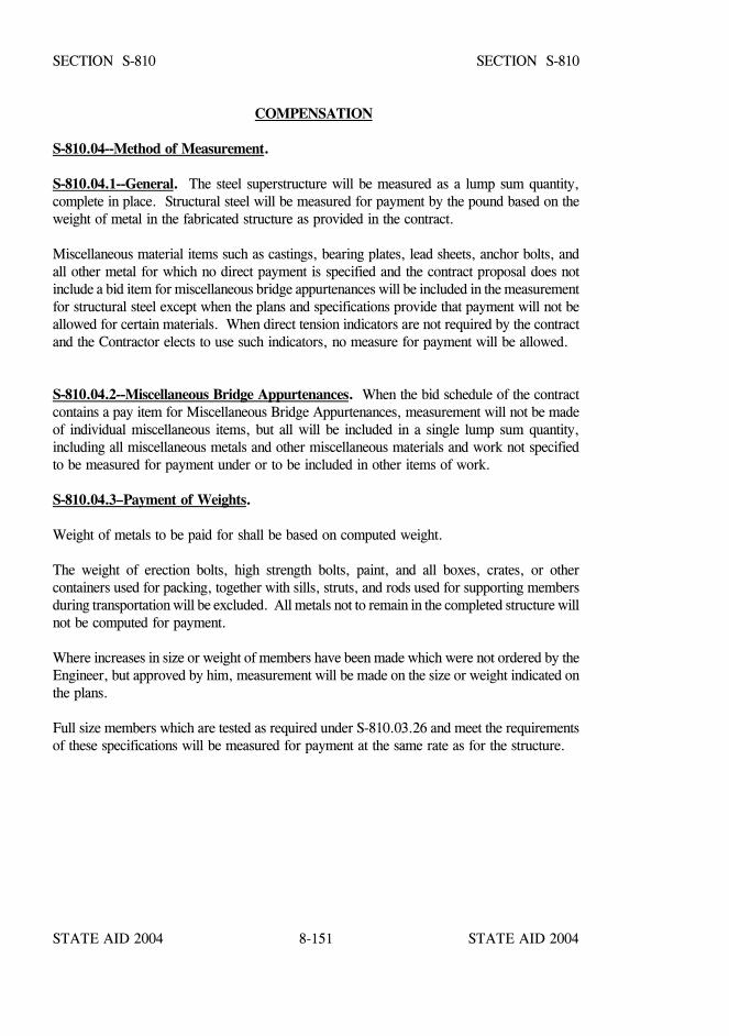
STATE AID 2004 STATE AID 2004
STATE AID 2004 STATE AID 20048-151
SECTION S-810 SECTION S-810
COMPENSATION
S-810.04--Method of Measurement.
S-810.04.1--General. The steel superstructure will be measured as a lump sum quantity,complete in place. Structural steel will be measured for payment by the pound based on theweight of metal in the fabricated structure as provided in the contract.
Miscellaneous material items such as castings, bearing plates, lead sheets, anchor bolts, andall other metal for which no direct payment is specified and the contract proposal does notinclude a bid item for miscellaneous bridge appurtenances will be included in the measurementfor structural steel except when the plans and specifications provide that payment will not beallowed for certain materials. When direct tension indicators are not required by the contractand the Contractor elects to use such indicators, no measure for payment will be allowed.
S-810.04.2--Miscellaneous Bridge Appurtenances. When the bid schedule of the contractcontains a pay item for Miscellaneous Bridge Appurtenances, measurement will not be madeof individual miscellaneous items, but all will be included in a single lump sum quantity,including all miscellaneous metals and other miscellaneous materials and work not specifiedto be measured for payment under or to be included in other items of work.
S-810.04.3–Payment of Weights.
Weight of metals to be paid for shall be based on computed weight.
The weight of erection bolts, high strength bolts, paint, and all boxes, crates, or othercontainers used for packing, together with sills, struts, and rods used for supporting membersduring transportation will be excluded. All metals not to remain in the completed structure willnot be computed for payment.
Where increases in size or weight of members have been made which were not ordered by theEngineer, but approved by him, measurement will be made on the size or weight indicated onthe plans.
Full size members which are tested as required under S-810.03.26 and meet the requirementsof these specifications will be measured for payment at the same rate as for the structure.
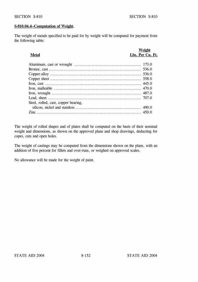
STATE AID 2004 STATE AID 2004
STATE AID 2004 STATE AID 20048-152
SECTION S-810 SECTION S-810
S-810.04.4--Computation of Weight.
The weight of metals specified to be paid for by weight will be computed for payment fromthe following table:
WeightMetal Lbs. Per Cu. Ft.
Aluminum, cast or wrought .................................................. 173.0Bronze, cast ..................................................................... 536.0Copper-alloy .................................................................... 536.0Copper sheet .................................................................... 558.0Iron, cast ........................................................................ 445.0Iron, malleable ................................................................. 470.0Iron, wrought ................................................................... 487.0Lead, sheet ...................................................................... 707.0Steel, rolled, cast, copper bearing, silicon, nickel and stainless ................................................. 490.0Zinc .............................................................................. 450.0
The weight of rolled shapes and of plates shall be computed on the basis of their nominalweight and dimensions, as shown on the approved plans and shop drawings, deducting forcopes, cuts and open holes.
The weight of castings may be computed from the dimensions shown on the plans, with anaddition of five percent for fillets and over-runs, or weighed on approved scales.
No allowance will be made for the weight of paint.

STATE AID 2004 STATE AID 2004
STATE AID 2004 STATE AID 20048-153
SECTION S-810 SECTION S-810
The weight of heads, nuts, single washers, DTIs when required and "threaded stick-through"of all high tensile strength shop bolts will be included on the basis of the following weights:
Diameter of BoltInches
Weight per 100Bolts, Pounds
1/25/83/47/8
1 1 1/81 1/41 3/81 1/2
19.7 31.7 52.4 80.4116.7165.1212.0280.0340.0
It shall be understood that the weight of the "threaded stick-through" of the bolts will be on thebasis of full-thread engagement. Full-thread engagement is defined as being accomplishedwhen the end of the bolt is flush with the outer face of the nut. The Contractor may at hisdiscretion furnish and use the next longer standard length of bolt than that necessary toaccomplish full-threaded engagement, at no additional cost to the Project.
S-810.04.5--Deduction for Fabrication Inspection Cost Overruns. Under separateagreement, the Engineer will contract with a private company to provide inspection servicesfor structural steel fabrication. By this agreement a maximum amount payable, including afixed fee will be established beyond which no funds will be authorized for payment without aSupplemental Agreement.
The structural steel fabrication inspection costs, not to exceed the established maximum amountpayable including the fixed fee and any additional amount authorized for payment bySupplemental Agreement, will be paid for from the Project Fund.
Structural steel fabrication inspection costs exceeding the above described amount will bededucted from monies due the Contractor under pay items S-810-A, S-810-B, and/or S-810-C,as the case may be.
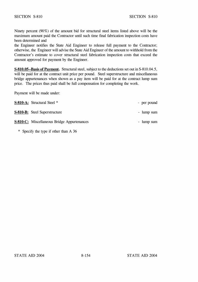
STATE AID 2004 STATE AID 2004
STATE AID 2004 STATE AID 20048-154
SECTION S-810 SECTION S-810
Ninety percent (90%) of the amount bid for structural steel items listed above will be themaximum amount paid the Contractor until such time final fabrication inspection costs havebeen determined andthe Engineer notifies the State Aid Engineer to release full payment to the Contractor;otherwise, the Engineer will advise the State Aid Engineer of the amount to withhold from theContractor’s estimate to cover structural steel fabrication inspection costs that exceed theamount approved for payment by the Engineer.
S-810.05--Basis of Payment. Structural steel, subject to the deductions set out in S-810.04.5,will be paid for at the contract unit price per pound. Steel superstructure and miscellaneousbridge appurtenances when shown as a pay item will be paid for at the contract lump sumprice. The prices thus paid shall be full compensation for completing the work.
Payment will be made under:
S-810-A: Structural Steel * - per pound
S-810-B: Steel Superstructure - lump sum
S-810-C: Miscellaneous Bridge Appurtenances - lump sum
* Specify the type if other than A 36
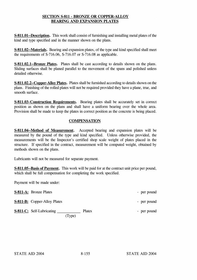
STATE AID 2004 STATE AID 2004
STATE AID 2004 STATE AID 20048-155
SECTION S-811 - BRONZE OR COPPER-ALLOYBEARING AND EXPANSION PLATES
S-811.01--Description. This work shall consist of furnishing and installing metal plates of thekind and type specified and in the manner shown on the plans.
S-811.02--Materials. Bearing and expansion plates, of the type and kind specified shall meetthe requirements of S-716.06, S-716.07 or S-716.08 as applicable.
S-811.02.1--Bronze Plates. Plates shall be cast according to details shown on the plans.Sliding surfaces shall be planed parallel to the movement of the spans and polished unlessdetailed otherwise.
S-811.02.2--Copper-Alloy Plates. Plates shall be furnished according to details shown on theplans. Finishing of the rolled plates will not be required provided they have a plane, true, andsmooth surface.
S-811.03–Construction Requirements. Bearing plates shall be accurately set in correctposition as shown on the plans and shall have a uniform bearing over the whole area.Provision shall be made to keep the plates in correct position as the concrete is being placed.
COMPENSATION
S-811.04--Method of Measurement. Accepted bearing and expansion plates will bemeasured by the pound of the type and kind specified. Unless otherwise provided, themeasurements will be the Inspector's certified shop scale weight of plates placed in thestructure. If specified in the contract, measurement will be computed weight, obtained bymethods shown on the plans.
Lubricants will not be measured for separate payment.
S-811.05--Basis of Payment. This work will be paid for at the contract unit price per pound,which shall be full compensation for completing the work specified.
Payment will be made under:
S-811-A: Bronze Plates - per pound
S-811-B: Copper-Alloy Plates - per pound
S-811-C: Self-Lubricating Plates - per pound (Type)

STATE AID 2004 STATE AID 2004
STATE AID 2004 STATE AID 20048-156
SECTION S-812 - STEEL GRID FLOORING
S-812.01--Description. This work shall consist of constructing steel grid flooring, open orconcrete-filled type as specified, in accordance with these specifications and in reasonably closeconformity to the lines and grades shown on the plans or established.
S-812.02--Materials. Materials used shall conform to the provisions of S-717.05.
S-812.02.1--Arrangement of Sections. Where the main elements are normal to centerline ofroadway, the units generally shall be of such length as to extend over the full width of theroadway up to 40 feet, but in every case the units shall extend over at least three panels.Where joints are required, the ends of the main floor members shall be welded at the jointsover their full cross-sectional area or otherwise connected to provide full continuity.
Where the main elements are parallel to centerline of roadway, the sections shall extend overat least three panels, and the ends of abutting units shall be welded over their fullcross-sectional area or otherwise connected to provide full continuity in accordance with thedesign.
S-812.02.2--Provisions for Camber. Unless otherwise provided on the plans, provision forcamber shall be made as follows:
Steel units so rigid that they will not readily follow the camber required shall becambered in the shop. To provide a bearing surface parallel to the crown of theroadway the stringers shall be canted or provided with shop-welded beveled bearingbars. If beveled bars are used, they shall be placed along the centerline of thestringer flange, in which case the design span length shall be governed by the widthof the bearing bar instead of by the width of the stringer flange.
Longitudinal stringers shall be mill cambered or provided with bearing strips so thatthe completed floor after dead-load deflection will conform to the longitudinal cambershown on the plans.
S-812.02.3--Welding. All shop and field welding shall be in accordance with S-810.03.5.
S-812.02.4--Repairing Damaged Galvanized Coatings. All galvanizing that has beenchipped off or damaged in handling or transporting or in welding or riveting shall be repairedby field galvanizing by the application of a paste composed of approved zinc powder and fluxwith a minimum amount of water. The places to be coated shall be thoroughly cleaned,including removal of slag on welds, before the paste is applied. The surface to be coated shallfirst be heated with a torch to a sufficient temperature so that all metallics in the paste aremelted when applied to the heated surface. Extreme care shall be taken to see that thegalvanized surfaces are not damaged by the torch. The flux in the paste will cause a blacksubstance to appear on the surface of the coated parts, and this black substance shall beremoved by wiping off with waste or by the quick application of cold water.
STATE AID 2004 STATE AID 2004
STATE AID 2004 STATE AID 20048-157
SECTION S-812 SECTION S-812
S-812.03–Construction Requirements.
S-812.03.1--Field Assembly. Areas of considerable size shall be assembled before the flooris welded to its supports. The main elements shall be made continuous, and sections shall beconnected together along their edges by welding of bars or by riveting them. The connectionsshall meet with the approval of the Engineer. The rivets may be cold driven.
S-812.03.2--Connection to Supports. The floor shall be connected to its steel supports bywelding. Before any welding is done, the floor shall either be loaded to make a tight joint withfull bearing, or it shall be clamped down. The location, length, and size of the welds shall besubject to the approval of the State Aid Engineer, but in no case shall they be less than themanufacturer's standards.
The ends of all the main steel members of the slab shall be securely fastened together at thesides of the roadway for the full length of the span by means of steel plates or angles weldedto the ends of the main members, or by thoroughly encasing the ends with concrete.
S-812.03.3--Concrete Filler. Floor types with bottom flanges not in contact shall be providedwith bottom forms of metal or wood to retain the concrete filler without excessive leakage.
If metal form strips are used they shall fit tightly on the bottom flanges of the floor membersand be placed in short lengths so as to extend only about one inch onto the edge of each sup-port, but in all cases the forms shall be such as will result in adequate bearing of slab on thesupport.
The concrete shall be mixed, placed, and cured in accordance with S-804. The concrete shallbe thoroughly compacted by vibrating the steel grid floor. The vibrating device and themanner of operating it shall be subject to the approval of the Engineer.
S-812.03.4--Painting. Flooring furnished without galvanizing but with a shop coat of paintshall be given field coats of paint in accordance with S-814.
When a structural steel plate is used on the bottom of a filled type floor, the bottom surface ofthe plate shall be given one shop coat, one field intermediate coat and one field top coat ofpaint in accordance with S-814.
STATE AID 2004 STATE AID 2004
STATE AID 2004 STATE AID 20048-158
SECTION S-812 SECTION S-812
COMPENSATION
S-812.04--Method of Measurement. Accepted steel grid floor will be measured by thesquare foot. This measurement shall include galvanizing or painting as specified and concretefilling when applicable.
S-812.05--Basis of Payment. This work will be paid for at the contract unit price per squarefoot of the type required, which shall be full compensation for completing the work specified.
Payment will be made under:
S-812-A: Steel Grid Floor (Open Type) - per square foot
S-812-B: Steel Grid Floor (Concrete Filled Type) - per square foot
STATE AID 2004 STATE AID 2004
STATE AID 2004 STATE AID 20048-159
SECTION S-813 - RAILING
S-813.01--General. This work shall consist of constructing bridge railing of the type specifiedin accordance with these specifications. Railing for bridges shall include all work constructedabove the top of the bridge deck, curb, or sidewalk surface, as applicable. Railing for precastbridges shall conform with S-806.
S-813.02--Materials. All materials shall conform to the requirements of S-700 or as specifiedin the special provisions or on the plans.
Unless otherwise specified, concrete shall be Class "B" meeting the requirements of S-804.
S-813.03–Construction Requirements.
S-813.03.1--Line and Grade. Lines and grades of railing shall be in reasonably closeconformity to that shown on the plans and shall not follow any unevenness in thesuperstructure. Unless otherwise specified or shown on the plans, the railing, posts, and curbson bridges, whether on horizontal grade, superelevated or not, shall be vertical.
S-813.03.2--Concrete Railing.
S-813.03.2.1--General. In no case shall concrete railings be placed until the centering orfalsework for the span has been released and the span is self-supporting.
S-813.03.2.2--Railings Cast-In-Place. The portion of the railing or parapet which is to becast in place shall be constructed in accordance with the requirements of S-804. Special careshall be exercised to secure smooth and tight-fitting forms which can be rigidly held to line andgrade and removed without injury to the concrete.
Steel forms, single width boards or other approved material shall be required for castingconcrete railing. Form joints in plane surfaces will not be permitted. The transition sectionof the rail is to be formed in accordance with the standard and not slip formed.
All moldings, panel work, and bevel strips shall be constructed according to the detail planswith neatly mitered joints, and all corners in the finished work shall be true, sharp, andclean-cut and shall be free from cracks, spalling, or other defects.
S-813.03.2.2.1--Slip Form Construction. The slip form method of construction may be usedfor cast-in-place rail construction with the approval of the Engineer.
If permitted, the equipment shall be self-contained, power propelled units with approvedautomatic control devices for maintaining both true line and elevation.
STATE AID 2004 STATE AID 2004
STATE AID 2004 STATE AID 20048-160
SECTION S-813 SECTION S-813
The concrete will be of a consistency so that there will be no slump or subsidence after thepassage of the forming equipment. It shall be the responsibility of the contractor to obtain aproper mix design for this type of placement prior to starting the work.
Joints will be sawed after the concrete has set and will be truly vertical. The location andwidth of the joints shall be as shown on the plans. The intermediate joints between the spanjoints are to be saw cut to a width of approximately 5/16 inch. The saw cut will leave a radiusat the bottom on the backside since the 24-inch radius blade will not completely pass over the32 inch high rail.
The span joints will be double cut to the exact width of the bridge deck span joint.
S-813.03.2.3--Surface Finish. The surfaces of concrete railings shall conform to therequirements of S-804.03.19.
S-813.03.2.4--Expansion Joints. Expansion joints shall be so constructed as to permitfreedom of movement. After all other work is completed, all loose or thin shells of mortarlikely to spall under movement shall be carefully removed from all expansion joints by meansof a sharp chisel.
S-813.03.3--Metal Railing.
S-813.03.3.1--Construction. Fabrication and erection of ferrous metal shall be in accordancewith the requirements of S-810. In the case of welded railings, all exposed joints shall befinished by grinding or filling to give a neat appearance.
Fabrication and erection of non-ferrous material shall be in general conformity with applicablerequirements of S-810 and the specific requirements shown on the plans.
Metal railings shall be carefully adjusted prior to fixing in place to insure proper matching atabutting joints and correct alignment and camber throughout their length. Holes for fieldconnections shall be drilled with the railing in place in the structure at the correct grade andalignment. Welding may be substituted for rivets in field connections with the approval of theEngineer.
Where galvanized ferrous metal railing is designated by the plans, the components shall be hotdip galvanized after fabrication in accordance with the requirements of the plans.
S-813.03.3.2--Painting. Painting shall conform to the requirements of S-710 and S-814.
S-813.03.4--Wood Railings. Wood railings will be constructed and paid for under theprovisions of S-820.
STATE AID 2004 STATE AID 2004
STATE AID 2004 STATE AID 20048-161
SECTION S-813 SECTION S-813
COMPENSATION
S-813.04--Method of Measurement. Accepted bridge railing will be measured by the linearfoot within the nominal measuring points of spans at bridge ends.
S-813.05--Basis of Payment. Bridge railing will be paid for at the contract unit price perlinear foot of the type specified, which shall be full compensation for completing the workspecified.
Payment will be made under:
S-813-A: Concrete Railing - per linear foot
S-813-B: Concrete-Steel Railing - per linear foot
S-813-C: Concrete-Aluminum Railing - per linear foot
S-813-D: Railing - per linear foot (Type)
STATE AID 2004 STATE AID 2004
STATE AID 2004 STATE AID 20048-162
SECTION S-814 - PAINTING METAL STRUCTURES
S-814.01--Description. This work consists of furnishing all materials and painting of metalstructures. It shall include, unless otherwise provided in the contract, the preparation of metalsurfaces, application, protection and drying of the paint coatings, supplying of all tackle,scaffolding and other essentials necessary to complete the work in reasonably close conformitywith the specifications and as indicated on the plans.
The Coating System will consist of one shop coat of inorganic zinc, one field intermediate coatof acrylic latex and one field top coat of acrylic latex. The shop coat, intermediate coat andtop coat shall each have a dry film thickness of not less than 3 mils nor more than 5 mils.
Touch-up paint for field repair of damaged areas in the inorganic zinc shop coat shall consistof epoxy mastic applied to a uniform dry film thickness of not less than 4 mils nor more than6 mills.
S-814.02--Material.
S-814.02.1--Shop Coat (Prime Coat). The paint shall be an inorganic zinc primer and meetthe requirements of S-710.04.1.
S-814.02.2--Acrylic Latex Intermediate Coat (Field Coat). The paint shall meet therequirements of S-710.04.3.
S-814.02.3--Acrylic Latex Top Coat (Field Coat). The paint shall meet the requirements ofS-710.04.3.
S-814.02.4--Epoxy Mastic Touch-up Paint. Field touch-up paint for repair of damagedinorganic zinc shop coat shall meet the requirements of S-710.04.2.
S-814.03--Construction Requirements:
S-814.03.1--Mixing of Paint. All paint shall be mixed in accordance with the manufacturer'sprinted instructions.
S-814.03.2--Weather Condition: Solvent base paint shall not be applied when thesurrounding air temperature is below 40oF. Waterborne paint shall not be applied when thesurrounding air temperature is below 50oF. Paint shall not be applied when the surroundingair temperature is expected to drop to 32oF prior to drying of the paint. Paint shall not beapplied when the metal is hot enough to cause blistering or produce a porous film. Paint shallnot be applied when the steel surface is less than 5oF above the dew point nor shall it beapplied in rain, snow, wind, fog, mist or when, in the opinion of the Engineer, conditions areotherwise unsatisfactory for the work.
STATE AID 2004 STATE AID 2004
STATE AID 2004 STATE AID 20048-163
SECTION S-814 SECTION S-814
S-814.03.3--Application:
S-814.03.3.1--Shop Coat. The coating shall be capable of being applied in accordance withspecification requirements and shall be applied in accordance with the manufacturer's printedinstructions.
After initial mixing, the paint shall be strained through a metal 30-60 mesh screen.
Stirring paddles on the mechanical mixing equipment shall reach to within one inch of thebottom of the paint container.
Airless spray equipment for application of inorganic zinc silicate paint shall provide pressureof not less than 2200 psi at the nozzle. The fluid hose between the pot and nozzle shall not beless than 3/8" inside diameter. Pressure may vary depending on tip size and pump.
Conventional spray equipment for application of inorganic zinc silicate paint shall providepressure of not less than 10 psi at the pot and 30 psi at the nozzle.
S-814.03.3.2--Acrylic Latex Intermediate and Top Coats (Field Coats). All applicationsof the acrylic latex intermediate and top coats shall be in accordance with the manufacturersprinted instructions. The primer coat and the intermediate coat shall have dried a minimumof eight hours under normal conditions prior to application for the intermediate and top coats,respectively. All surfaces shall be free of any soluble residue and surfaces on which theprimer coat has been applied shall be free of excessive amounts of loose zinc before asubsequent coat is applied. Dust and dirt which may have accumulated on the surface shall beremoved from the dried film with a soft brush or rag before application of a subsequent coat.When applied by brushing or spraying, the coating shall deposit a uniform dry film thicknesswithout running or sagging.
S-814.03.4--Removal of Paint. If any painting is unsatisfactory, it shall be removed and themetal thoroughly cleaned and repainted.
S-814.03.5--Thinning Paint. Paint shall be thinned only in strict accordance with themanufacturer's recommendations.
S-814.03.6--Painting Galvanized Surfaces. Prior to application of the acrylic latex fieldcoats, galvanized surfaces shall be primed with Epoxy Mastic Touch-Up Paint as specified inS-814.02.
S-814.03.7--Cleaning of Surfaces. Surfaces to be painted shall be thoroughly cleaned,removing rust, loose mill scale, dirt, oil or grease and other foreign substances.
STATE AID 2004 STATE AID 2004
STATE AID 2004 STATE AID 20048-164
SECTION S-814 SECTION S-814
All exposed and accessible surfaces of the metal shall be cleaned by sandblasting in accordancewith the requirements of Steel Structures Painting Council SSPC-SP-10, Near White BlastCleaning. The surface, regardless of starting condition, shall in the opinion of the Engineeror his designated representative be at least equal to the appearance of Pictorial SwedishStandard Sa 2 1/2 of SIS 05 59 00, SSPC-VIS 1.
All rust blooms shall be removed by reblasting before coating. The surface shall be constantlyand diligently examined ahead of the coating operations for any traces of rust, oil, grease orblemishes not permitted by the blast cleaning specifications.
S-814.03.8--Shop Painting: Unless otherwise specified, the shop coat shall be appliedimmediately after the steel work has been accepted by the inspector.
Shop contact surfaces shall not be painted. Field contact surfaces except for machine finishedpins and holes shall receive a shop coat with a minimum dry film thickness of 1 1/2 mils. Allother surfaces which will be inaccessible after assembly or erection shall be given all requiredcoats.
Surfaces which will be embedded or in contact with concrete shall not require painting unlessotherwise noted on the plans. They may be painted in whole or partially due to oversprayprovided the paint thickness does not exceed the requirements specified for adjacent areas.
Structural steel which is to be field welded shall not be shop painted within two inches of thefield welds.
All surfaces of iron and steel casting except for machine finished pins and holes shall be giventwo shop coats of paint.
Erection marks for field identification of members and weight marks shall be painted on areaspreviously painted with the shop coat. Material shall not be loaded for shipment until it isthoroughly dry and no sooner than 24 hours after the paint has been applied.
S-814.03.9--Field Painting. When the erection work is complete, including all bolting andstraightening of bent metal, all rust, scale, dirt, grease and other foreign material shall beremoved. As soon as the Engineer has approved all field welding and bolting, the surfacesfrom which the shop coat of paint has worn off or otherwise become defective shall be cleanedand reprimed with the specified touch-up paint prior to application of the intermediate coat.
STATE AID 2004 STATE AID 2004
STATE AID 2004 STATE AID 20048-165
SECTION S-814 SECTION S-814
Spans with concrete decks shall not be painted until after the deck is placed. All concrete spillsand stains shall be washed from the structural steel prior to the mortar taking a set.
Surfaces to be bolted in contact and surfaces which will be in contact with concrete shall nothave a field coat applied.
When the paint applied for retouching the shop coat has thoroughly dried and the field cleaninghas been satisfactorily completed, the intermediate coat shall be applied. After the intermediatecoat has thoroughly dried, the top coat shall be applied.
In no case shall a subsequent coat be applied until the previous coat has dried throughout thefull thickness of the paint film. To secure a maximum coating on edges of plates or shapes,bolt heads and other parts subjected to special wear and attack, the edges shall be stripped witha longitudinal motion and bolt heads with a rotary motion of the brush followed immediatelyby the general painting of the whole surface, including recoating of the edges and bolt heads.
If, in the opinion of the Engineer, traffic produces an objectionable amount of dust, theContractor shall, at his own expense, allay the dust for the necessary distance on each side ofthe bridge and take any other precautions necessary to prevent dust and dirt from coming incontact with freshly painted surfaces or surfaces prepared for painting.
The Contractor shall protect pedestrian, vehicular and other traffic upon or underneath thebridge and also all portions of the bridge superstructure and substructure against damage ordisfigurement by spatters, splashes and smirches of paint or paint material. Any suchdisfigurement shall be removed at the direction of and to the satisfaction of the Engineer.
S-814.03.10--Inspection. The completed shop coat shall be inspected by the Contractor forthickness by means of elcometer or other approved magnetic detector thickness gage.Detection of insufficiently coated sections shall be marked and shall be coated over or touchedup to establish the specified thickness.
All areas of the finished system deficient in thickness shall be coated over with the acrylic latextop coat paint to establish the specified thickness. Excessive thickness in the application of anycoating evidenced by mudcracking will be cause for the affected area to be blast-cleaned andrepainted.
Where rejection is due to poor workmanship or deficiency in the quality of the work ormaterials, the Contractor may be required to blast clean the entire defective sections of allpreviously applied materials prior to repainting.
STATE AID 2004 STATE AID 2004
STATE AID 2004 STATE AID 20048-166
SECTION S-814 SECTION S-814
Inspection shall be done in the presence of and to the satisfaction of the Engineer. TheEngineer shall be provided access to the work to allow for proper inspection of the cleaningand painting at both the fabrication plant and the construction site.
S-814.04--Method of Measurement. Unless shown as a separate pay item in the proposal,painting of metal structures or members will not be measured for separate payment and the costthereof shall be incidental to and included in the contract unit price(s) bid for other items.
S-814.05--Basis of Payment. When shown as a separate pay item in the proposal, paintingwill be paid for at the contract lump sum price which shall be full compensation for completingthe work.
Payment will be made under:
S-814-A: Painting of Metal Structure - lump sum
S-814-B: Painting of - lump sum (Description)
STATE AID 2004 STATE AID 2004
STATE AID 2004 STATE AID 20048-167
SECTION S-815 - RIP RAP AND SLOPE PAVING
S-815.01--Description. This work consists of furnishing and placing a protective covering oferosion resistant material including plastic filter fabric, where shown on the plans for pierfoundation protection, slope, or ditch protection. This work shall be in accordance with thesespecifications and in reasonably close conformity with the lines, grades and dimensions shownon the plans or established.
S-815.02--Materials. Materials shall conform to the following:
Geotextile fabric shall meet the requirements of S-714.13.
Aggregate for loose rip rap, stone rip rap for foundation protection, or that to be grouted shallconsist of field stone, broken concrete, or rough, unhewn quarry stone as nearly rectangularin section as is practicable. The stone shall be dense, free of clay or shale seams, resistant tothe action of air and water, and suitable in all other respects for the purpose intended. Qualityrequirements for rock to be furnished under these specifications will be checked or tested asdetermined by the MDOT Testing Engineer prior to use and subsequently if deemedappropriate.
Portland cement concrete aggregates, unless otherwise specified, shall conform to theapplicable requirements of S-703.
Cloth sacks for concrete riprap in bags shall be of suitable cloth or jute which will hold theconcrete mixture without leakage when handled. The sacks shall be of uniform size anddimensions, approximately 19½ x 36 inches measured inside the seams when the sack is laidflat. Sound reclaimed cloth sacks meeting the specified requirements may be used.
Paper sacks for concrete riprap in bags shall be a polyester fiber type of scrim reinforcedpaper. The top and bottom of the sacks shall have a pasted valve. When filled, they shallmeasure approximately 13 inches wide, 20 inches long, and five inches thick. Perforationsshall be overall on one-inch centers with a diameter of 3/32 inch to 1/8 inch per hole. Eachbag shall fill a space of approximately 0.71 cubic feet with 38 bags required per cubic yard.Pre-packaged riprap will be accepted on certification from the manufacturer.
Stones for rip rap, of the size specified, shall meet the requirements of S-705.04.
Material used for sediment control stone shall be crushed stone meeting the requirements ofSubsection 703.03 for Size No. 57.
STATE AID 2004 STATE AID 2004
STATE AID 2004 STATE AID 20048-168
SECTION S-815 SECTION S-815
S-815.03--Construction Requirements.
S-815.03.1--Construction Details. Prior to the construction of rip rap or slope paving, theslopes or ground surface shall be shaped to lines and grades indicated on the plans or directed,and shall be thoroughly compacted by the use of mechanical or hand tamps. Unless otherwisestipulated or directed, slopes shall not be steeper than the natural angle of repose of thematerial upon which rip rap is to be constructed.
The outer edges and the top of the rip rap or slope paving where the construction terminatesshall be formed so that the surface of the rip rap or slope paving will be embedded and evenwith the surface of the adjacent slope or ground, and the bottom of the rip rap or slope pavingshall be placed at least two feet below the natural ground surface unless otherwise directed.
All rip rap or slope paving shall be started at the bottom of the slope and constructed upward.
No grout, bag rip rap, or slope paving shall be placed during freezing weather or while thereis frost in the ground. In hot or dry weather grout and bag rip rap shall be kept moist and pro-tected from the sun for at least three days after placing. Slope paving shall be cured inaccordance with the provisions of S-815.03.7.4.
S-815.03.2--Installation of Geotextile Fabric. When required by the contract, geotextile shallbe placed in the manner and at locations shown on the plans. The area to receive the geotextileshall be prepared to a relatively smooth condition free of obstructions, depressions and debris.The geotextile shall be placed loosely without wrinkles or creases with the long dimensionperpendicular to the channel. The strips shall be placed to provide a minimum overlap of 18inches. Securing pins with washers shall be inserted through both strips of overlappedgeotextile at mid-point and not greater than two foot intervals. Additional pins shall beinstalled throughout the geotextile as necessary to prevent any slippage. The geotextile shallbe placed so that the upstream strip overlaps the downstream strip and the higher slope stripoverlaps the lower strip. Each securing pin shall be pushed through the geotextile until thewasher bears against the geotextile and secures it firmly.
The geotextile shall be protected from contamination and damage during installation andplacement of the specified cover material. Riprap shall not be dropped from a height greaterthan three feet. Contaminated geotextile shall be replaced, and damaged geotextile shall berepaired or replaced as directed at no cost to the Project.
The geotextile shall be covered with a layer of the specified material within 14 calendar daysafter placement. Geotextile not covered within this time period shall be removed and replacedat the Contractor's expense if damage or deterioration is evident, as determined by theEngineer.
STATE AID 2004 STATE AID 2004
STATE AID 2004 STATE AID 20048-169
SECTION S-815 SECTION S-815
S-815.03.3--Loose Riprap. The stones shall be placed upon a slope not steeper than thenatural angle of repose of the slope material. The stones shall be laid with close joints. Thecourses shall be laid from the bottom of the bank upward with the larger stones being placedin the lower courses. Interstices shall be filled with smaller stones and spalls.
S-815.03.4--Grouted Riprap. Grout for grouted riprap shall consist of one part of Portlandcement and three parts of approved sand thoroughly mixed with water to produce grout havinga thick, creamy consistency.
The stones shall be of the size designated in the bid schedule of the contract and shall be placedin the same manner as specified for loose riprap.
Care shall be taken during placement to keep earth or sand from filling the spaces between thestones. After the stones are in place, the spaces between them shall be completely filled withgrout from bottom to top and the surface swept with a stiff broom.
S-815.03.5--Stone Riprap for Foundation Protection. Stone riprap for pier and abutmentprotection shall range in size up to derrick stone and shall be graded from coarse to fine insuch a manner as to produce a minimum of voids. It shall be deposited where directed. Stonedeposited contrary to directions will be considered wasted and will not be paid for.
S-815.03.6--Concrete Riprap in Bags. Concrete riprap in bags shall consist of Class "D"concrete in approved bags and placed in conformity with contract requirements. Each bagshall be filled with approximately one cubic foot of concrete, securely tied, and immediatelyplaced in the work and lightly trampled to cause them to conform with the slope or sectionrequired with adjacent bags in place. Unless otherwise specified in the contract, the baggedconcrete shall be packed in such a manner as to give a reasonably uniform thickness ofapproximately 12 inches and shall be lapped and staggered as directed.
Pre-packaged riprap in paper bags shall be filled with kiln- dried mixture of portland cementand sand, or cement, sand and gravel with a ratio of three parts sand or sand and gravel to onepart portland cement. The bags shall be placed to conform with the slope or required sectionand with adjacent bags in place. The bags shall be lapped and staggered as directed.
When shown on the plans, pipe headwalls shall be constructed of riprap in bags in accordancewith these specifications and the plan details. In this construction, it is essential that thesuccessive tiers are securely "keyed" by lapping, and the bags of concrete shall be lapped byat least one-half their length, when practicable.
STATE AID 2004 STATE AID 2004
STATE AID 2004 STATE AID 20048-170
SECTION S-815 SECTION S-815
S-815.03.7--Slope Paving. Concrete slope paving shall be constructed in a single layer inconformity with the design dimensions and details indicated on the plans.
S-815.03.7.1--Forms. Forms shall be wood or metal of sufficient strength to withstand thepressure of the concrete without bulging. They shall be adequately and securely staked trueto line and grade.
S-815.03.7.2--Mixing and Placing Concrete. Unless otherwise stipulated, the concrete usedin this construction shall be Class "C", mixed and placed in accordance with the provisions andrequirements of S-804, except that volumetric batching may be used. Mixers of less than onebag rated capacity shall not be used.
S-815.03.7.3--Finishing. Concrete after spreading, shall be tamped and puddled until it iscompact and sufficient mortar has been flushed to the surface so that it can be finished smoothwith a wooden float. All edges shall be neatly edged using an approved short radius sidewalkedger.
S-815.03.7.4--Curing. After the concrete has set sufficiently, the surface shall be protectedfrom premature drying by covering as soon as possible with a satisfactory material such aswetted burlap or wetted cotton mats and kept moist for a minimum of three days, or cured byother approved methods. Other approved methods include liquid membrane compound as setout in S-713.01.2, and polyethylene sheeting (white) conforming with the requirements ofS-713.01.3. Both liquid membrane compound and polyethylene sheeting shall be maintainedin place and intact for a minimum period of three days.
S-815.03.7.5--Soil Sterilization. Prior to placing slope pavement, the areas beneath thepavement shall receive soil sterilization treatment as set out in S-616.04.
S-815.03.8--Cleaning Up. Upon completion of the work, the surface of the riprap or slopepaving shall be cleaned, surplus material and debris removed and disposed of as directed, andthe site of the work left in a neat presentable condition.
COMPENSATION
S-815.04--Method of Measurement. Loose rip rap complete in place and accepted will bemeasured in square yards or in tons, as specified. The pay area will be determined by usingthe outside dimensions of the area covered as directed. Tons or fraction thereof will bedetermined by railway weights or other satisfactory and approved method for determiningweight. Stone placed contrary to directions will not be paid for.
Measurement or payment will not be made for grout, and the cost thereof shall be included inthe compensation for grouted rip rap.
STATE AID 2004 STATE AID 2004
STATE AID 2004 STATE AID 20048-171
SECTION S-815 SECTION S-815
Concrete rip rap in bags will be measured in cubic yards as the quantity received ormanufactured at the site of the work and acceptably placed in bags as required, but from theamount received or manufactured at the site, there will be deducted all excess determined bythe Engineer to have been wasted or placed to unauthorized dimensions.The cubic yards ofpre-package riprap in paper bags will be determined from the actual count of bags placed andaccepted based on 38 bags per cubic yard.
Slope paving will be measured by the cubic yard computed using the dimensions shown on theplans, except that if authorized revisions are made in the finish grade or the configuration ofthe slope pavement, computations will be made considering the changed dimensions.
Geotextile complete in place and accepted will be measured by the square yard of surface areacovered. Any extra width of material installed and additional material required for laps orsewing will not be measured. No separate payment shall be made for shipping, handling,storage, protection, fabrication, securing pins, or installation; the cost of which shall beincluded in the contract price for geotextile fabric.
S-815.05--Basis of Payment. Loose riprap will be paid for at the contract unit price persquare yard or ton. Sediment control stone will be paid for at the contract unit price per cubicyard or ton. Grouted riprap will be paid for at the contract unit price per square yard.Concrete riprap in bags and concrete slope paving will be paid for at the contract unit price percubic yard. Geotextile will be paid for at the contract unit price per square yard. Suchpayment shall be full compensation for completing the work.
Payment will be made under:
S-815-A: Loose Riprap, lb. - per ton
S-815-A-1: Loose Riprap, lb. - per square yard
S-815-B: Grouted Riprap - per square yard
S-815-C: Concrete Riprap in Bags - per cubic yard
S-815-D: Concrete Slope Paving - per cubic yard
S-815-E: Geotextile under , Type * , AOS * - per square yard (Description)
S-815-F: Sediment Control Stone - per ton
S-815-F-1: Sediment Control Stone - per cubic yard
* When not designated, see S-714.13.
STATE AID 2004 STATE AID 2004
STATE AID 2004 STATE AID 20048-172
SECTION S-816 - MAINTENANCE PAINTING OF METAL STRUCTURES
S-816.01--Description. This work consists of furnishing all materials, equipment and laborfor the cleaning and painting of metal structures. It shall include, unless otherwise providedin the contract, the preparation of metal surfaces, the application, protection and drying of thepaint coatings, supplying all tackle, scaffolding and other essentials necessary to complete thework in accordance with the specifications and as specified on the plans.
S-816.02--Materials. The coating system selected for maintenance painting must be lead free,VOC compliant and must be listed on the MDOT's Approved List of Materials under“Approved Coating Systems for Upgrading Existing Coatings by Maintenance Forces”. Thecoating system shall consist of three coats as follows; an approved primer coat paint,intermediate coat paint and a top coat paint. The substitution of a primer, intermediate or topcoat paint from one approved coating system to another is not permitted. The integrity of eachapproved coating system must be maintained.
When the project requires the painting of both new and existing metal structures, the differentpainting systems selected shall be from the same manufacturer and shall have the same top coatcolor.
S-816.03--Construction Requirements.
S-816.03.1--Weather Limitations. Solvent base paint shall not be applied when thesurrounding air temperature is below 40oF. Waterborne paint shall not be applied when thesurrounding air temperature is below 50oF. Paint shall not be applied when the surroundingair temperature is expected to drop to 32oF prior to drying of the paint. Paint shall not beapplied when the metal is hot enough to cause blistering or produce a porous film. Paint shallnot be applied when steel surface is less than 5oF above the dew point nor shall it be appliedin rain, snow, wind, fog, mist or when, in the opinion of the Engineer, conditions areotherwise unsatisfactory for the work.
S-816.03.2--Pollution Control During Surface Preparation And Repainting. Generateddebris must be confined to the immediate area of the structure. Appropriate screens andbarriers must be erected to protect pedestrian and vehicular traffic during waterblasting andpainting operation. Overspray must be kept to a bare minimum.
S-816.03.3--Surface Preparation. Surface preparation will include waterblasting the entiresurface followed by spot cleaning with hand tools to remove any remaining loose or flakingpaint or rust, dirt, oil, grease and/or other deleterious matter from the steel surface. Tightlybonded paint is not to be removed and it is not necessary to remove tightly bonded rust.
STATE AID 2004 STATE AID 2004
STATE AID 2004 STATE AID 20048-173
SECTION S-816 SECTION S-816
In areas containing a heavy coating of oil, grease and/or deleterious material that cannot becleaned by waterblasting, use BIOACT AE-O or an approved biodegradable solvent that isenvironmentally equivalent. Brush or mop the solvent on the surface with a rubbing actionto loosen the film. Wipe off with a clean dry cloth and then rinse by waterblasting. Repeatas necessary until clean. The cleanliness of the surface shall be approved by the Engineer ora designated representative prior to beginning painting operations.
S-816.03.3.1--Waterblasting. The waterblasting unit must be capable of operating atpressures up to 4,000 psi at a water flow rate up to 10 gpm. The unit must be equipped witha water filter, pressure gage, nozzle with 1/8-inch orifice or one that will provide a jet streamof water, and sufficient length of hydraulic hose. The unit shall be equipped with a deadmancontrol valve or other control valves that will provide automatic shut-off by release of thetrigger. Water for blasting must be potable water to prevent damage to the pump and to insurea clean surface on the steel. During waterblasting operation, wood, insulation, electrical,instrumentation, etc., must be protected. After waterblasting, remove any remaining loosepaint, loose rust and rust scale with wire brushes or other methods as necessary. Using thewaterblast unit or compressed air, remove the loose debris generated from the hand toolcleaning operation. To prevent recontamination of the steel surface, the surface preparationoperation should not be completed more than eight hours in advance of the painting operation.Should any recontamination occur prior to painting, repeat surface preparation procedures asnecessary for removal. Before painting, the surfaces must be clean and dry. To enhancedrying of the surfaces, compressed air may be used.
S-816.03.3.2--Safety and Clean-Up. During the cleaning of the existing steel, the Contractormay be dealing with hazardous material and the Contractor will be responsible for the healthand safety of employees. The Contractor shall provide such items as protective clothing andrespirators and make certain that they are used. The Contractor shall also be responsible forthe maintenance and/or replacement of these items. The Contractor is advised that safetyprecautions for workers during each phase of work shall be in compliance with present OSHAstandards.
The Contractor shall take necessary precautions to prevent an excessive amount of removedmaterials from falling beneath the structure. General debris must be confined to the immediatearea of the structure. Appropriate measures shall be taken to protect the traveling publicduring surface preparation and painting operations.
The Contractor shall clean the area of excessive debris generated from cleaning and properlydispose of it at an approved landfill.
The Contractor shall take necessary steps to become familiar with any applicable Federal, Stateor local regulations and take the necessary actions for compliance when applicable to anyportion of the required work.

STATE AID 2004 STATE AID 2004
STATE AID 2004 STATE AID 20048-174
SECTION S-816 SECTION S-816
S-816.03.4--Packaging and Marking. Multiple component paints shall be furnished inpremeasured packages so as to form one unit of mixed paint when mixed with the vehicle inits container.
The containers for all paints shall be coated as necessary to prevent attack by the paint. Eachcontainer shall bear a label with the following information shown thereon: name and addressof manufacturer, trade mark or trade name, kind of paint, date of manufacture and lot number,mixing instructions and equipment clean up instructions. The Volatile Organic Compounds(VOC) content shall be stated either on the label, product data sheet, or Material Safety DataSheet.
S-816.03.5--Acceptance Procedure. Prior to use, the Contractor must furnish the Engineera certificate from the manufacturer, covering each lot of paint in the shipment, attesting thatthe paint in the shipment conforms to the same formula as that originally approved by MDOT.
Final acceptance of the paint will be based on Manufacturer’s Certification. The Engineerreserves the right to sample paint as he deems necessary. The use of any lot of paint prior tothe Engineer’s approval shall be prohibited.
S-816.03.6--Mixing, Thinning and Application. All paint shall be mixed and applied inaccordance with the manufacturer's printed instructions. Paint shall be thinned only underconditions which follow strict accordance with the manufacturer's recommendations.
At the Engineer's request, the paint manufacturer's technical representative who is certified bythe National Association of Corrosion Engineers (NACE) shall be present at the job site at thebeginning of each separate coating operation as needed to provide technical expertise in theapplication of the field coats. This technical expertise shall be provided without additional costto the Project. The Contractor shall be responsible for arranging for the presence of themanufacturer's technical representative.
Apply the paint to the Wet Film Thickness (WFT) that will obtain the Dry Film Thickness(DFT) required for the film being applied. The DFT required for each paint film of eachapproved coating system is set out in the MDOT's Approved List of Materials.
A subsequent coat shall not be applied until the previous coat has dried throughout the filmthickness.
To secure a maximum coating on edges of plates or shapes, rivets, bolt heads and other partssubjected to special wear and attack, the edges shall be stripped with a longitudinal motion andthe rivets and bolt heads with a rotary motion of a brush followed immediately by generalpainting of the whole surface, including recoating of the edges, rivets and bolt heads.
STATE AID 2004 STATE AID 2004
STATE AID 2004 STATE AID 20048-175
SECTION S-816 SECTION S-816
If, in the opinion of the Engineer, traffic produces an objectionable amount of dust, theContractor shall, at no additional costs to the Project, allay the dust for the necessary distanceon each side of the bridge and take any other precautions necessary to prevent dust and dirtfrom coming in contact with freshly painted surfaces or surfaces prepared for painting.
The Contractor shall protect pedestrian, vehicular and other traffic upon or underneath thebridge and also all portions of the bridge superstructure and substructure against damage ordisfigurement by splatters, splashes and smirches of paint or paint material. Any suchdisfigurement shall be removed at the direction of, and to the satisfaction of the Engineer.
S-816.03.7--Inspection. The Contractor shall measure the paint thickness with an elcometeror other approved magnetic detector thickness gages. All areas of the finished system deficientin thickness shall be coated over with the finish paint to establish the specified thickness.Excessive thickness in the application of either coating evidenced by mudcracking will be causefor the effected area to be stripped of paint, cleaned and repainted.
Where rejection is due to poor workmanship or deficiency in the quality of the work ormaterials, the Contractor may be required to strip the entire defective sections of all previouslyapplied materials and clean prior to repainting.
Inspection shall be done in the presence of and to the satisfaction of the Engineer.
S-816.04--Method of Measurement. Maintenance painting of structures and members willbe measured lump sum or per each as provided in the contract.
S-816.05--Basis of Payment. Maintenance painting of structures and members will be paidfor at the contract unit price per each or lump sum, which price will be full compensation forpreparation of the surface, for furnishing and applying all materials and for all labor, tools,equipment and incidentals necessary to complete the work.
Payment will be made under:
S-816-A: Maintenance Painting of Metal Structure - lump sum
S-816-B: Maintenance Painting of Metal Structure, - per each (Location / Description)
S-816-C: Maintenance Painting of - lump sum(Description)
Sections S-817 thru S-819 - Blank.
STATE AID 2004 STATE AID 2004
STATE AID 2004 STATE AID 20048-176
SECTION S-820 - TIMBER STRUCTURES
S-820.01--Description. This work consists of constructing timber structures in conformitywith these specifications and in accordance with lines, grades, dimensions, and details shownon the plans.
S-820.02--Materials.
S-820.02.1--Lumber and Timber. Lumber and timber shall conform to the requirements ofS-718, and in the case of exposed permanent structures shall be treated as set out therein.Certain portions of untreated timber shall be coated as set out hereinafter and as may be shownon the plans.
S-820.02.2--Rods, Plates, Eyebars, and Shapes. Rods, plates, eyebars, and shapes shall beof structural steel conforming to the requirements of S-717.
S-820.02.3--Castings. Castings shall be cast steel or gray-iron, as specified, conforming tothe requirements of S-716.02 or S-716.04.
S-820.02.4--Hardware. Machine bolts, drift bolts, and dowels may be either wrought ironor medium steel. Washers may be cast ogee or malleable castings, or they may be cut frommedium steel or wrought iron plate, as specified.
Unless otherwise specified, machine bolts shall have square heads and nuts. Nails shall be cutor round wire of standard form. Spikes shall be cut or wire spikes, or boat spikes, asspecified.
Nails, spikes, bolts, dowels, washers, and lag screws shall be galvanized unless otherwisespecified.
S-820.03--Construction Requirements.
S-820.03.1--Storage of Material. Lumber and timber stored on the site shall be kept inorderly piles or stacks. Untreated material shall be open-stacked on supports at least 12 inchesabove the ground surface to avoid absorption of ground moisture and to permit air circulation,and it shall be so stacked and stripped as to permit free circulation of air between the tiers andcourses. It will be advisable in particular cases for the Engineer to require protection from theweather by a suitable covering. On glued laminated structural members that are not to betreated, an approved end sealer shall be applied after end trimming of each completed member.
S-820.03.2--Installing Timber Piling.
S-820.03.2.1--Driving Piling. Timber piles shall be driven in accordance with therequirements of S-803.03.1, except as modified herein.
STATE AID 2004 STATE AID 2004
STATE AID 2004 STATE AID 20048-177
SECTION S-820 SECTION S-820
S-820.03.2.2--Pile Hammer Formula. Pile hammer formulas shall be per the requirementsof S-803.03.1.9.2, except the use of gravity or drop hammers shall be allowed. In the absenceof loading test, safe bearing values for piles driven with a gravity or drop hammer shall bedetermined by the following formula:
P = 2WH for gravity or drop hammersS+1.0
S-820.03.3--Timber Connectors. Timber connectors shall be one of the following types, asspecified on the plans: the split ring, the toothed ring, the shear plate, or the spike grid. Thesplit ring and the shear plate shall be installed in pre-cut grooves of dimensions as given hereinor as recommended by the manufacturer. The toothed ring and the spike grid shall be forcedinto the contact surface of the timbers joined by means of pressure equipment. All connectorsof this type at a joint shall be embedded simultaneously and uniformly.
Fabrication of all structures using connectors shall be done prior to treatment. Whenprefabricated from templates or shop details, bolt holes shall not be more than 1/16 inch fromrequired placement. Holes for round drift bolts shall be bored with a bit 1/16 inch less thanthe bolt to be used. The diameter for square drift bolts shall be equal to the least dimensionof the bolt. Holes for machine bolts shall be bored with a bit the same diameter as the bolt.Bolt holes shall be bored perpendicular to the face of the timber.
Timber after fabrication shall be stored in a manner which will prevent changes in thedimensions of the members before assembly.
Dimensions of material and details not otherwise specified shall meet with the approval of theEngineer.
S-820.03.4--Treated Timber.
S-820.03.4.1--Handling. Treated timber shall be carefully handled without sudden dropping,breaking of outer fibers, bruising, or penetrating the surface with tools. It shall be handledwith rope slings. Cant hooks, peaveys, spikes, or hooks shall not be used. Prior to driving,the timber piling shall not be handled in such a manner that it is subjected to excessive andundue abuse that might produce splitting, splintering or brooming of the wood.
S-820.03.4.2--Placement. All cutting, framing, and boring of treated timber shall be donebefore treatment insofar as practicable. When treated timbers are to be placed in watersinfected by marine borers, untreated cuts, borings, or other joint framings below high waterelevation shall be avoided.
STATE AID 2004 STATE AID 2004
STATE AID 2004 STATE AID 20048-178
SECTION S-820 SECTION S-820
S-820.03.4.3--Cuts and Abrasions. All cuts in treated piles or timbers, and all abrasions,after having been carefully trimmed, shall be covered with two applications of a mixture of 60percent creosote oil and 40 percent roofing pitch, or brush coated with at least two applicationsof hot creosote oil and covered with hot roofing pitch.
S-820.03.4.4--Bolt Holes. All bolt holes bored after treatment shall be treated with creosoteoil by means of an approved pressure bolt hole treater. Any unfilled holes, after being treatedwith creosote oil, shall be plugged with creosoted plugs.
S-820.03.4.5--Temporary Attachment. Whenever, with the approval of the Engineer, formsor temporary braces are attached to treated timber with nails or spikes, the holes shall be filledby driving galvanized nails or spikes flush with the surface or plugging holes as required forbolt holes.
S-820.03.5--Untreated Timber. In temporary structures of untreated timber the followingsurfaces shall be thoroughly coated with two coats of hot creosote oil before assembling: ends,tops, and all contact surfaces of sills, caps, floor beams, and stringers; and all ends, joints, andcontact surfaces of bracing and truss members. The back faces of bulkheads and all othertimber which is to be in contact with earth, metal or other timber shall be similarly treated.
Bolts passing through non-resinous wood shall be galvanized.
S-820.03.6--Treatment of Pile Heads. The heads of treated timber piles shall be protectedas specified on the plans. If not specified, the fabric covering shall be used. The heads oftimber piles, when the nature of the driving will unduly injure them, shall be protected bydriving caps. When the area of the head of a timber pile is greater than that of the face of thepile hammer, a suitable cap shall be provided to distribute the blow of the hammer throughoutthe cross section of the pile. Fresh heading of a timber pile is recommended prior to driving.The head shall be cut square and shall be shaped or chamfered to prevent splitting at itsperiphery. Heads of all piling shall be square and a driving cap shall be provided to hold theaxis of the pile in line with the axis of the hammer.
S-820.03.6.1--Cutting Off of Timber Piles. The tops of all piling shall be sawed to a trueplane, as shown on the plans, and at the elevation fixed by the Engineer. Piles which supporttimber caps or grillage shall be sawed to conform to the plane of the bottom of thesuperimposed structure. In general, the length of pile above the cut-off elevation shall besufficient to permit the complete removal of all material injured by driving, but piles driven tovery nearly the cut-off elevation shall be carefully adzed or otherwise freed from all broomed,splintered or otherwise injured material. Pile heads, after cutting to receive the caps and priorto placing the caps, shall be treated in accordance with S-820.03.6.
STATE AID 2004 STATE AID 2004
STATE AID 2004 STATE AID 20048-179
SECTION S-820 SECTION S-820
S-820.03.6.2--Defective Piles. All piles damaged because of internal defects or by improperdriving, driving out of the proper location, or driving below the specified elevation shall becorrected at no additional costs to the Project by one of the following methods approved by theEngineer for the pile in question:
A. The pile shall be withdrawn and replaced by a new, and if necessary, alonger pile.
B. A second pile shall be driven adjacent to the defective or low pile.
C. A sufficient portion of the footing shall be extended to properly embed thepile. Timber piles shall not be spliced except as indicated on the plans formaintenance type projects. All piles pushed up by the driving of adjacentpiles or by any other cause shall be driven down again.
S-820.03.6.3--Metal Covering. The sawed surface shall be covered with three applicationsof a mixture of 60 percent creosote oil and 40 percent roofing pitch or thoroughly brush-coatedwith three applications of hot creosote oil and covered with hot roofing pitch. Before placingthe cap, a sheet of 12 gage, 0.028-inch zinc of good commercial quality or a sheet of 26 gageiron or steel of the quality of ASTM Designation: A 525 and galvanized each side shall beplaced on each pile head. The sheet shall be of sufficient size to project at least four inchesoutside of the pile, and it shall be bent down, neatly trimmed and securely fastened to the faceof the pile with large headed galvanized roofing nails.
S-820.03.6.4--Fabric Covering. The heads of all piles shall be covered with alternate layersof hot pitch and loosely woven fabric similar to membrane waterproofing, using fourapplications of pitch and three layers of fabric. The cover shall measure at least six inchesmore in dimensions that the diameter of the pile and shall be neatly folded down over the pileand secured by large headed galvanized nails or by binding or serving with not less than sevencomplete turns of galvanized wire securely held in place by large-headed galvanized nails andstaples. The edges of the fabric projecting below the wire wrapping shall be trimmed to presenta workmanlike appearance.
The heads of untreated piles shall be given one of the following treatments, as may be specifiedor directed by the Engineer:
A. The sawed surface shall be thoroughly brush-coated with two applicationsof hot creosote oil.
B The sawed surface shall be heavily coated with paint, after which it shall becovered with cotton duck of a least eight-ounce weight, which shall befolded down over the sides of the pile and firmly secured thereto withlarge-headed roofing nails. The edges of the duck shall be trimmed to givea workmanlike appearance. The duck shall then be waterproofed by beingthoroughly saturated and coated with one or more applications of approvedpaint.
STATE AID 2004 STATE AID 2004
STATE AID 2004 STATE AID 20048-180
SECTION S-820 SECTION S-820
S-820.03.7--Holes for Bolts, Dowels, Rods and Lag Screws. Holes for round drift bolts anddowels shall be bored with a bit 1/16 inch less in diameter than the bolt or dowel to be used.The diameter of holes for square drift bolts or dowels shall be equal to the least dimension ofthe bolt or dowel.
Holes for machine bolts shall be bored with a bit the same diameter as the bolt, except asotherwise provided in S-820.03.3.
Holes for rods shall be bored with a bit 1/16 inch greater in diameter than the rods.
Holes for lag screws shall be bored with a bit not larger than the body of the screw at the baseof the thread.
S-820.03.8--Bolts and Washers. A washer, of the size and type specified, shall be used underall bolt heads and nuts which would otherwise come in contact with wood.
The nuts of all bolts shall be effectively locked after they have been finally tightened.
S-820.03.9--Framing. All lumber and timber shall be accurately cut and framed to a close fitin such manner that the joints will have even bearing over the entire contact surfaces. Mortisesshall be true to size for their full depth, and tenons shall fit snugly. No shimming will bepermitted in making joints, nor will open joints be accepted.
S-820.03.10--Pile Bents. Pile bents shall be constructed in accordance with applicableprovisions of S-803.
S-820.03.11--Framed Bents.
S-820.03.11.1--Mud Sills. Untreated timber used for mud sills shall be of heart cedar, heartcypress, redwood, or other durable timber. Mud sills shall be firmly and evenly bedded tosolid bearings and tamped in place.
S-820.03.11.2--Concrete Pedestals. Concrete pedestals for the support of framed bents shallbe carefully finished so that the sills or posts will take even bearing on them. Dowels of atleast 3/4-inch diameter and projecting at least six inches above the tops of the pedestals shallbe set in them when they are cast for anchoring the sills or posts.
S-820.03.11.3--Sills. Sills shall have true and even-bearing on mud sills, piles, or pedestals.They shall be drift-bolted to mud sills or piles with bolts of not less than 3/4-inch diameter andextending into the mud sills or piles at least six inches. When possible, all earth shall beremoved from contact with sills so that there will be free air circulation around them.
STATE AID 2004 STATE AID 2004
STATE AID 2004 STATE AID 20048-181
SECTION S-820 SECTION S-820
S-820.03.11.4--Posts. Posts shall be fastened to pedestals with dowels of not less than3/4-inch diameter extending at least six inches into the posts.
Posts shall be fastened to sills by one of the following methods, as indicated on the plans:
A. By dowels of not less than 3/4-inch diameter extending at least six inchesinto posts and sills.
B. By drift bolts of not less than 3/4-inch diameter driven diagonally throughthe base of the post and extending at least nine inches into the sill.
S-820.03.12--Caps. Timber caps shall be placed, with ends aligned, in a manner to secure aneven and uniform bearing over the tops of the supporting posts or piles. All caps shall besecured by drift bolts of not less than 3/4-inch diameter extending at least nine inches into theposts or piles. The drift bolts shall be approximately in the center of the post or pile.
S-820.03.13--Bracing. The ends of bracing shall be bolted through the pile, post or cap witha bolt of not less than 5/8-inch diameter. Intermediate intersections shall be bolted, or spikedwith wire or boat spikes, as indicated on the plans. In all cases spikes shall be used in additionto bolts.
S-820.03.14--Stringers. Stringers shall be sized at bearings and shall be placed in position sothat knots near edges will be in the top portions of the stringers.
Outside stringers may have butt joints with the ends cut on a taper, but interior stringers shallbe lapped to take bearing over the full width of the floor beams or cap at each end. The lappedends of untreated stringers shall be separated at least 1/2 inch for the circulation of air and shallbe securely fastened by drift-bolting where specified. When stringers are two panels in lengththe joints shall be staggered.
Cross-bridging between stringers shall be neatly and accurately framed and securely toe nailedwith at least two nails in each end. All cross-bridging members shall have full bearing at eachend against the sides of stringers. Unless otherwise specified in the contract, cross-bridgingshall be placed at the center of each span.
S-820.03.15--Plank Floors. Unless otherwise specified, planks used in this construction shallconform to the requirements set forth in S-820.02.1.
STATE AID 2004 STATE AID 2004
STATE AID 2004 STATE AID 20048-182
SECTION S-820 SECTION S-820
Single plank floor shall consist of a single thickness of plank supported by stringers or joists.The planks shall be laid heart side down, with 1/4-inch openings between them for seasonedmaterial and with tight joints for unseasoned material. Each plank shall be securely spiked toeach joist. The planks shall be carefully graded as to thickness and so laid that no two adjacentplanks shall vary in thickness by more than 1/4 inch.
Two-ply timber floors shall consist of two layers of flooring supported on stringers or joists.The lower course shall be pressure treated with creosote oil. The top course may be laid eitherdiagonally or parallel to the centerline of roadway as specified, and each floor piece shall besecurely fastened to the lower course. Joints shall be staggered at least three feet. If the topflooring is placed parallel to the centerline of the roadway, special care shall be taken tosecurely fasten the ends of the flooring. At each end of the bridge these members shall bebeveled.
S-820.03.16--Laminated or Strip Floors. The strips shall be of the grade required in S- 718.The strips shall be placed on edge at right angles to the centerline of the roadway. Each stripshall be spiked to the preceding strip at each end and at approximately 18-inch intervals withthe spikes driven alternately near the top and bottom edges. The spikes shall be of sufficientlength to pass through two strips and at least half-way through the third strip.
If timber supports are used, every other strip shall be toe-nailed to each timber support. Thesize of the spikes shall be as shown on the plans. When specified on the plans, the strips shallbe securely attached to steel supports by the use of approved galvanized metal clips. Care shallbe taken to have each strip vertical and tight against the preceding one and bearing evenly onall the supports.
S-820.03.17--Wheel Guards and Railing. Wheel guards and railing shall be accuratelyframed in accordance with the plans and erected true to line and grade. Unless otherwisespecified, wheel guards, rails and rail posts shall be surfaced four sides, S4S. Wheel guardsshall be laid in sections at least 12 feet long.
S-820.03.18--Countersinking. Countersinking shall be done wherever smooth faces arerequired. Horizontal recesses formed for countersinking shall be painted with hot creosote oil,and after the bolt or screw is in place shall be filled with hot pitch.
S-820.03.19--Painting. Rails and rail posts of untreated timber, or timber treated withpreservative salts, shall be painted with three coats of paint.
Parts of the structure, other than rails and rail posts, which are to be painted, will bedesignated on the plans or in the special provisions.
STATE AID 2004 STATE AID 2004
STATE AID 2004 STATE AID 20048-183
SECTION S-820 SECTION S-820
Metal parts, except hardware, shall be given one coat of shop paint and after erection two coatsof field paint as specified on the plans.
S-820.04--Method of Measurement. Timber remaining in the structure will be measured bythe thousand feet board measure (MBM) which shall include the cost of all hardware,galvanizing, paint and painting. Computations of the amount of lumber and timber in thestructure will be based on nominal sizes and the lengths indicated on the plans.
Piling will be measured in accordance with S-803.04.
Metal parts, other than hardware, will be measured in accordance with S-810.
S-820.05--Basis of Payment. Timber will be paid for at the contract unit price per thousandfeet board measure, which price shall be full compensation for completing the work.Acceptable piling will be paid for at the respective contract prices per linear foot for the typesand sizes specified, which price shall be full compensation for completing the work.
Payment will be made under:
S-820-A: Treated Timber - per MBM
S-820-B: Untreated Timber - per MBM
S-820-C: Untreated Timber Piling - per linear foot
S-820-D: Treated Timber Piling - per linear foot
Section S-821 - Blank.

STATE AID 2004 STATE AID 2004
STATE AID 2004 STATE AID 20048-184
SECTION S-822 - NEOPRENE EXPANSION JOINTS
S-822.01--Description. This work consists of furnishing and installing neoprene expansionjoints in accordance with these specifications and details shown on the plans.
S-822.02--Materials. Expansion joints shall meet the requirements of S-707.07.
S-822.03--Construction Methods. Expansion joints shall be installed in accordance with themanufacturer's recommendations. The expansion material shall seal the deck surface, guttersand curbs to prevent moisture or other contaminants from leaking through the joints. Anchorbolts shall be cast-in-place or drilled and grouted at a spacing recommended by themanufacturer. The expansion material shall be installed in such a manner that the top surfaceof the material will be parallel to but not protrude above the roadway or bridge surface.
S-822.04--Method of Measurement. Neoprene expansion joints of the types specified willbe measured in linear feet.
S-822.05--Basis of Payment. Neoprene expansion joints will be paid for at the contract unitprice per linear foot, which price shall be full compensation for completing the work.
Payment will be made under:
S-822-A: ___" Neoprene Expansion Joint, Type - per linear foot
Sections S-823 thru S-899 - Blank.
STATE AID 2004 STATE AID 2004
STATE AID 2004 STATE AID 20041
INDEX
A
Section orTopic Subsection Page
Abbreviations of Organizationsand Reference Materials,Definition of S-101.01 1-1
AcceptanceFinal S-105.16 1-40Final Payment S-109.11 1-89
Additive, Definition of S-101.02 1-3Adjustment of Castings,
Grading, UtilityAppurtenances S-613 6-58
Adjustments and Disputes,Claims for S-105.17 1-41
Admixture, Definition of S-101.02 1-3For Concrete S-713.02 7-85
Advancement on Materials S-109.06.2 1-84Advance on Materials
Payment for S-109.07 1-85Advertisement, Definition of S-101.02 1-3
For Bids S-102 1-14Affidavit, Non-Collusion S-102.06 1-17Aggregates S-703 7-20
Bedding Material for Pipe Culverts S-603.04 6-10Bedding Course, or Filter Material for Underdrains S-704 7-39Coarse, for Portland Cement
Concrete S-703.03 7-22 Dense-Graded Crushed
Stone for Bases S-703.04 7-25Filter Material S-704 7-39Fine, for Mortar Sand S-703.18 7-35Fine, for Portland Cement Concrete S-703.02 7-20For Bituminous Surface Treatments S-703.14 7-32For Granular Materials S-703.07 7-28For Hot Mix Asphalt S-703.06 7-26For Stabilizer S-703.20 7-35General S-703.01 7-20Mineral Filler S-703.16 7-34Tables of Gradation S-703.07.2 7-28
STATE AID 2004 STATE AID 2004
STATE AID 2004 STATE AID 20042
Section orTopic Subsection Page
Aggregate for Drainage S-704 7-39Agreement, Supplemental S-101.02 1-11
S-104.02 1-25Agricultural Limestone S-212 2-35
S-715.02.2.1 7-109Air-Entrained Concrete S-804.02.10.1.2 8-58Altered Quantities, Payment
& Compensation for S-109.03 1-81Alternate,
Design S-101.02 1-3Items S-101.02 1-3
Amounts Due Contractors S-109.01 1-78Anchorage for Guard Rail S-606.04 6-37Anionic Emulsified Asphalt S-702.07.2 7-13Approach Embankment
for Bridges S-203.05 2-11S-801.09 8-4
Approval of Contract S-103.07 1-24Arch Pipe and Horizontal
Elliptical Pipe, Concrete S-603 6-9Arch Pipe, Metal S-709.02 7-62Artifacts, Historical
of Archeological S-203.03 2-11Asphalt:
Application Temperatures Table IV S-702.11 7-16Cement(Petroleum) S-702.05 7-11Coated Fiber Glass Roving S-230 2-52Cutback S-702.06 7-13Emulsified S-702.07 7-13Pavement S-400 4-1Tack Coat S-407 4-41
Asphaltic Cement orPetroleum Asphalt S-702.12 7-17
Asphalt-Coated fiber Glass Roving S-230 2-52Assembling Steel S-810.03.28.10 8-150Audit, Right to S-109.12 1-89Authority & Duties of Inspectors S-105.10 1-37Authority of the Engineer S-105.09 1-37Availability of Plans & Proposals S-102.02 1-14Award:
And Execution of Contract S-103.02 1-21Cancellation of S-103.03 1-22Definition of S-101.02 1-3of Contract S-103.02 1-21
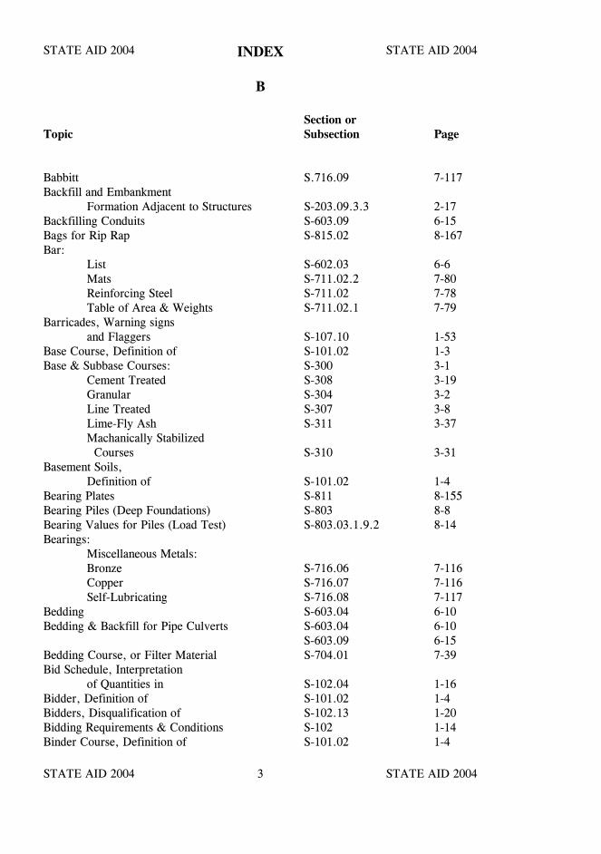
STATE AID 2004 STATE AID 2004
STATE AID 2004 STATE AID 20043
INDEX
B
Section orTopic Subsection Page
Babbitt S.716.09 7-117Backfill and Embankment
Formation Adjacent to Structures S-203.09.3.3 2-17Backfilling Conduits S-603.09 6-15Bags for Rip Rap S-815.02 8-167Bar:
List S-602.03 6-6Mats S-711.02.2 7-80Reinforcing Steel S-711.02 7-78Table of Area & Weights S-711.02.1 7-79
Barricades, Warning signsand Flaggers S-107.10 1-53
Base Course, Definition of S-101.02 1-3Base & Subbase Courses: S-300 3-1
Cement Treated S-308 3-19Granular S-304 3-2Line Treated S-307 3-8Lime-Fly Ash S-311 3-37Machanically Stabilized Courses S-310 3-31
Basement Soils,Definition of S-101.02 1-4
Bearing Plates S-811 8-155Bearing Piles (Deep Foundations) S-803 8-8Bearing Values for Piles (Load Test) S-803.03.1.9.2 8-14Bearings:
Miscellaneous Metals:Bronze S-716.06 7-116Copper S-716.07 7-116Self-Lubricating S-716.08 7-117
Bedding S-603.04 6-10Bedding & Backfill for Pipe Culverts S-603.04 6-10
S-603.09 6-15Bedding Course, or Filter Material S-704.01 7-39Bid Schedule, Interpretation
of Quantities in S-102.04 1-16Bidder, Definition of S-101.02 1-4Bidders, Disqualification of S-102.13 1-20Bidding Requirements & Conditions S-102 1-14Binder Course, Definition of S-101.02 1-4
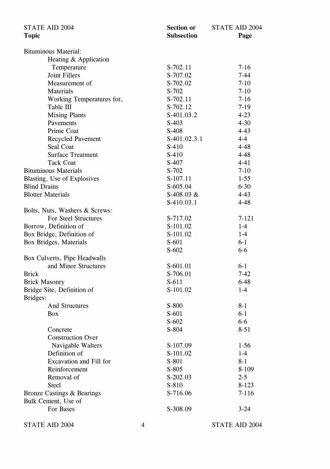
STATE AID 2004 STATE AID 2004
STATE AID 2004 STATE AID 20044
Section orTopic Subsection Page
Bituminous Material:Heating & Application Temperature S-702.11 7-16Joint Fillers S-707.02 7-44Measurement of S-702.02 7-10Materials S-702 7-10Working Temperatures for, S-702.11 7-16Table III S-702.12 7-19Mixing Plants S-401.03.2 4-23Pavements S-403 4-30Prime Coat S-408 4-43Recycled Pavement S-401.02.3.1 4-4Seal Coat S-410 4-48Surface Treatment S-410 4-48Tack Coat S-407 4-41
Bituminous Materials S-702 7-10Blasting, Use of Explosives S-107.11 1-55Blind Drains S-605.04 6-30Blotter Materials S-408.03 & 4-43
S-410.03.1 4-48Bolts, Nuts, Washers & Screws:
For Steel Structures S-717.02 7-121Borrow, Definition of S-101.02 1-4Box Bridge, Definition of S-101.02 1-4Box Bridges, Materials S-601 6-1
S-602 6-6Box Culverts, Pipe Headwalls
and Minor Structures S-601.01 6-1Brick S-706.01 7-42Brick Masonry S-611 6-48Bridge Site, Definition of S-101.02 1-4Bridges:
And Structures S-800 8-1Box S-601 6-1
S-602 6-6Concrete S-804 8-51Construction Over Navigable Walters S-107.09 1-56Definition of S-101.02 1-4Excavation and Fill for S-801 8-1Reinforcement S-805 8-109Removal of S-202.03 2-5Steel S-810 8-123
Bronze Castings & Bearings S-716.06 7-116Bulk Cement, Use of
For Bases S-308.09 3-24
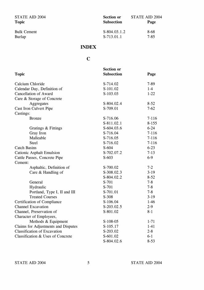
STATE AID 2004 STATE AID 2004
STATE AID 2004 STATE AID 20045
Section orTopic Subsection Page
Bulk Cement S-804.03.1.2 8-68Burlap S-713.01.1 7-85
INDEX
C
Section orTopic Subsection Page
Calcium Chloride S-714.02 7-89Calendar Day, Definition of S-101.02 1-4Cancellation of Award S-103.03 1-22Care & Storage of Concrete
Aggregates S-804.02.4 8-52Cast Iron Culvert Pipe S-709.01 7-62Castings:
Bronze S-716.06 7-116S-811.02.1 8-155
Gratings & Fittings S-604.03.6 6-24Gray Iron S-716.04 7-116Malleable S-716.05 7-116Steel S-716.02 7-116
Catch Basins S-604 6-23Cationic Asphalt Emulsion S-702.07.2 7-13Cattle Passes, Concrete Pipe S-603 6-9Cement:
Asphaltic, Definition of S-700.02 7-2Care & Handling of S-308.02.3 3-19
S-804.02.2 8-52General S-701 7-8Hydraulic S-701 7-8Portland, Type I, II and III S-701.01 7-8Treated Courses S-308 3-19
Certification of Compliance S-106.04 1-46Channel Excavation S-203.02.5 2-9Channel, Preservation of S-801.02 8-1Character of Employees,
Methods & Equipment S-108-05 1-71Claims for Adjustments and Disputes S-105.17 1-41Classification of Excavation S-203.02 2-8Classification & Uses of Concrete S-601.02 6-1
S-804.02.6 8-53
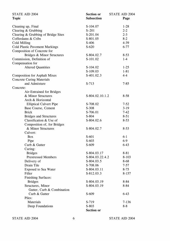
STATE AID 2004 STATE AID 2004
STATE AID 2004 STATE AID 20046
Section orTopic Subsection Page
Cleaning up, Final S-104.07 1-28Clearing & Grubbing S–201 2-2Clearing & Grubbing of Bridge Sites S-201.04 2-3Cofferdams & Cribs S-801.05 8-2Cold Milling S-406 4-39Cold Plastic Pavement Markings S-620 6-77Composition of Concrete for
Bridges & Minor Structures S-804.02.7 8-53Commission, Definition of S-101.02 1-4Compensation for
Altered Quantities S-104.02 1-25S-109.03 1-81
Composition for Asphalt Mixes S-401.02.3 4-4Concrete Curing Materials
and Admixture S-713 7-85Concrete:
Air-Entrained for Bridges& Minor Structures S-804.02.10.1.2 8-58Arch & Horizontal Elliptical Culvert Pipe S-708.02 7-52Base Course, Cement S-308 3-19Brick S-706.01 7-42Bridges and Structures S-804 8-51Classification & Use of S-804.02.6 8-53Composition of, for Bridges & Minor Structures S-804.02.7 8-53Culvert: Box S-601 6-1
Pipe S-603 6-9Curb & Gutter S-609 6-43Curing: Bridges S-804.03.17 8-81 Prestressed Members S-804.03.22.4.2 8-103Delivery of S-804.03.5 8-68Drain Tile S-708.06 7-57Exposed to Sea Water S-804.03.11 8-75Filler S-812.03.3 8-157Finishing Surfaces: Bridges S-804.03.19 8-84Structures, Minor S-804.03.19 8-84 Gutter, Curb & Combination Curb & Gutter S-609 6-43Piles: Materials S-719 7-136 Deep Foundations S-803 8-8
Section or

STATE AID 2004 STATE AID 2004
STATE AID 2004 STATE AID 20047
Topic Subsection Page
Sheet Piling S-802.02.1 8-6 Test Piles S-803.03.1.11 8-20
S-803.04.1 8-45Pipe: S-708 7-52 Cattle Pass S-708.03 7-57 Culverts S-603 6-9 Underdrains S-605 6-28Placement S-803.03.2.7 8-38Railing S-813 8-159Ready-Mix S-804.02.11 8-60Seal S-804.03.9 8-73Sewer Pipe S-603.06.2 6-14Sidewalks & Driveways S-608 6-40Steps & Minor Structures S-601 6-1Under Water S-804.03.9 8-73
Concreting:Cold Weather S-804.03.16.1 8-79Hot Weather S-804.03.16.2 8-81
Conduit:Drainage S-603 6-9
Conformity:Definition of S-101.02 1-5Determination of S-700.04 7-5With Plans and Specifications S-105.03 1-32
Consideration of Proposals S-103.01 1-21Construction Change Request,
Definitions of S-101.02 1-5Construction Joints:
Bituminous Pavements S-401.03.12 4-29Cement Treated Course(Construction Requirements-General) S-308.04 3-21Concrete Structures S-804.03.10 8-74
Construction Over Navigable Waters S-107.09 1-53Construction & Maintenance of Detours
and or Diversions S-104.04 1-26Construction Stakes, Lines & Grades S-105.08 1-37Contemplated Means Value (C.M.V.) S-700.02 7-2Contents of Proposal Forms S-102.02 1-14Contract:
Approval of S-103.07 1-24Award of S-103.02 1-21Bond: Requirement of S-103.05 1-22Default & Termination of S-108.08 1-74Execution of S-103.07 1-24
STATE AID 2004 STATE AID 2004
STATE AID 2004 STATE AID 20048
Section orTopic Subsection Page
Failure to Execute S-103.08 1-24Forms S-102.02 1-14Intent of S-104.01 1-25Payment Bond(Surety), Definition of(See Contract Bond) S-101.02 1-5Performance Bond, Definition of(See Contract Bond) S-101.02 1-7Subletting or Assignment of S-108.01 1-68Termination of Contract’s Responsibility S-108.10 1-77Time, Determination & Extension of S-108.06 1-72Contract Unit Price S-101.02 1-5
Contractor:Cooperation Between Contractors S-105.07 1-36Cooperation by S-105.05 1-33Definition of S-101.02 1-5Furnished Sources S-106.02.2 1-45Contractor’s Responsibility for Utility Property & Service S-107.18 1-59Contractor’s Responsibility For Work S-107.17 1-58 Termination of Responsibility S-108.10 1-77
Control of Materials S-106 1-44Control of Work S-105 1-31Controlling Work,
Definition of S-101.02 1-5Cooperation Between Contractors S-105.07 1-36Cooperation by Contractor S-105.05 1-33Cooperation with Utilities S-105.06 1-34Coordination of Plans
Specifications, Supplementalspecifications, Special Provisions,and Notice(s) to Bidders S-105.04 1-33
Copper Bearings & Sheet Copper S-716.07 7-116Corrugated Aluminum Pipe
Underdrains S-709.10 7-63Corrugated Metal Culvert Pipe
& Pipe Arches S-709.02 7-62Corrugated Metal Pipe for Underdrains S-709.06 7-63Corrugated Perforated Plastic Pipe S-708.17 7-58Cost of Repairs S-107.17 1-58County, Definition of S-101.02 1-6Creosote Oil & Creosote Coal
Tar Solution S-718.04 7-132Cross Slope, Definition of S-101.02 1-6
STATE AID 2004 STATE AID 2004
STATE AID 2004 STATE AID 20049
Section orTopic Subsection Page
Culvert, Definition of S-101.02 1-6Excavation S-603.03 6-10Pipe S-603 6-9Pipe Relaid S-603.07 6-14
Culverts and Storm Drains S-603 6-9Culverts, Box, Concrete S-601 6-1Curb & Combination Curb & Gutter S-609 6-43Curing Materials S-713.01 7-85Cutback Asphalts S-702.06 7-13
INDEX
D
Damage ClaimsResponsibility for S-107.14 1-57
Default & Terminationof Contract S-108.08 1-74
Defective Materials & Work S-105.12 1-38Definitions and Terms
Glossary of TermsMaterials & Tests S-700.02 7-1
Delivery of Proposal S-102.09 1-19Department, Definition of S-101.02 1-6Design Grade, Definition of S-101.02 1-6Design Soil, Definition of S-101.02 1-6Determination & Extension
of Contract Time S-108.06 1-72Determination of Conformity S-700.04 7-5Detour or Diversion, Construction
& Maintenance of S-104.04 1-26Director, Definition of S-101.02 1-6Disputes and Claims S-105.17 1-41Disqualification of Bidders S-102.13 1-20Documentation,
Definition of S-101.02 1-6Dowel Bars S-711.02.4 7-80Downspouts S-603 6-9Drain Tile S-708.06 7-57Drawings, Working S-105.02 1-31Driers for Paints S-710.01 7-66Drilled Shafts S-803.03.2 8-20Duties of the Inspector S-105.10 1-37
STATE AID 2004 STATE AID 2004
STATE AID 2004 STATE AID 200410
INDEX
E
Section orTopic Subsection Page
Earthwork S-203 2-8Earthwork, Maintenance of S-203.11 2-19Elastometric Bearings S-714.10 7-93Elements of Geometric
Design, Definition of S-101.02 1-6Eliminated Items S-109.05 1-83Embankments:
Areas, Preparation of S-203.09.2 2-14Compaction of S-203.09.4 2-18Construction S-203.09 2-14Formation of S-203.09.3 2-15
Emulsified Asphalt S-702.07 7-13Engineer:
Authority of S-105.01 1-31Definition of S-101.02 1-6
Environmental Protection S-107.22 1-61Erosion Control Fabrics S-231 2-54Estimates, Interpretation of S-102.04 1-16Examination of Plans, Specifications,
Special Provisions,Notice to Bidders, and Siteof Work S-102.05 1-16
Excavation:And embankment S-203 2-8And Fill for Bridges S-203.05 2-11Borrow S-203.02.4 2-8Channel S-203.02.5 2-9Classification of S-203.02 2-8Estimated On Site (E.O.S.E.) S-203.02.10 2-9Foundation Excavation for Bridges S-801.01 8-1Muck S-203.02.3 2-8Rock S-203.02.2 2-8Stripping S-203.02.9 2-9Structure excavation for Culverts, Boxes & Minor Structures S-206 2-24Surplus S-203.02.8 2-9Unclassified S-203.02.1 2-8
Excelsior, Blanket S-227 2-48Execution & Approval of
Contract S-103.07 1-24
STATE AID 2004 STATE AID 2004
STATE AID 2004 STATE AID 200411
Section orTopic Subsection Page
Explosives, Use of S-107.11 1-55Extension of Contract time S-108.06 1-72Extra Depth Excavation
for Bridges S-801.10 8-4S-801.11 8-5
Extra & Force Account Work,Payment for S-109.04 1-81
Extra Work S-109.04 1-81Extra Work, Definition of S-101.02 1-6Eyebars S-810.03.15 8-142
INDEX
F
Fabricated Bar or WireMesh Mats S-711.02 7-78
Failure to complete Workon Time S-108.07 1-73
Failure to Execute Contract S-103.08 1-24Failure to Maintain Roadway
or Structures S-105.15 1-40Falsework (for Bridges) S-804.03.13 8-75Falsework and Forms and
Housing, Removal of S-804.03.15 8-78Federal Aid Participation S-107.05 1-51Fertilizer for Plant Material S-212 2-35Fertilizers S-212.02 2-35Fertilizing S-212.05 2-36Figure 1-Pavement Structure S-100 1-93Filler, Mineral S-703.16 7-34Filter Material S-704 7-39Final Acceptance S-105.16 1-40Final Cleaning Up S-104.07 1-28Final Payment S-109.11 1-89Fine Aggregate for Portland
Cement Concrete S-703.02 7-20Finishing Concrete:
Bridge Floors S-804.03.19.7 8-91Surfaces: Bridges S-804.03.19.6.3 8-87 Sidewalks S-804.03.19.9 8-99 Structures, Minor S-804.03.19.6.2 8-87
Flaggers S-618.03.2 6-69
STATE AID 2004 STATE AID 2004
STATE AID 2004 STATE AID 200412
Section orTopic Subsection Page
Flared End Sections,Concrete S-708.04 7-57
Flowable Fill S-631 6-91Fly Ash S-714.05 7-91Force Account Work S-109.04 1-81Forest Protection S-107.13 1-56Foundation Excavation for Bridges S-801.01 8-1Frames, Grates, Covers and
Ladder Rungs S-714.08 7-93Freight Rates and Labor Rates S-109.09 1-88Fuel Adjustment S-109.08 1-85Furnishing Right-of-Way S-107.19 1-60
INDEX
G
Galvanized Pipe S-716.11 7-117General Provisions S-100 1-1Geogrid Embankment Stabilization S-240 2-66Geometric Design, Definition
of Elements of S-101.02 1-6Geotextile Fabrics S-714.13 7-104Glass Beads S-710.03.5 7-68Glossary of terms & Definitions: S-101.01 1-1
S-700.02 7-1Grade and Line S-105.08 1-37Grade Separation Structures S-107.08 1-52Granular Courses S-304 3-2Granular Materials for Subbase
and Base Courses S-304.02 3-2Gravel Aggregate for Concrete
and Bituminous Mixed S-703 7-20Gray Iron Castings S-716.04 7-116Grillage, Placing of S-804.03.18.8 8-84Ground Preparation S-212.04 2-35Grout S-714.11 7-98Grouting S-804.03.22.4.4 8-104Guard Post, Materials S-718 7-130Guard Post, Construction S-606.03 6-36Guard Rail S-606 6-35
S-712 7-84Guardrail Posts, Materials S-606.02.3 6-35
STATE AID 2004 STATE AID 2004
STATE AID 2004 STATE AID 200413
INDEX
H
Hammers for Piles S-803.03.1.7.3 8-11Hazardous or Toxic Waste S-107.25 1-66Header Curb S-609 6-43Headwalls:
Bag Rip Rap S-815.03.6 8-169Concrete S-601 6-1Precast Flared End Sections S-708.04 7-57
High Tensile Strength Bolts S-717.02 7-121High Voltage Overhead Lines S-105.06.1 1-35Highway, Definition of S-101.02 1-7Holes for Prestressing bars S-804.03.22.3.3 8-103Holidays S-101.02 1-7Hot Mix Asphalt Pavement S-403 4-30Hot Spray Paint Traffic Markings S-619 6-72Hourly Rental Schedule S-109.04 1-82Hydrated Lime S-714.03.2 7-89Hydraulic Cement S-701 7-8
INDEX
I
Imperfect Trench Method S-603.10 6-15Increment, Definition of S-700.02 7-2Inlets S-604 6-23Inspector, Authority of S-105.10 1-37
Definition of S-101.02 1-7Duties of S-105.10 1-37
Insurance, Public Liability S-103.06 1-22Items, Eliminated S-109.05 1-83Intent of Contract S-104.01 1-25Intent of Plans &
Specifications S-102.05 1-16Interpretation of Quantities
in Bid Schedule S-102.04 1-16Invitation for Bids,
Definition of S-101.02 1-8
STATE AID 2004 STATE AID 2004
STATE AID 2004 STATE AID 200414
INDEX
J
Section orTopic Subsection Page
Joining Conduit S-603.06 6-12Joint Bids S-102.01 1-14Joint Filler and Seals S-707 7-44Joint Materials S-707 7-44Joints:
Cleaning and Sealing S-413 4-71For Bituminous Pavement S-401.03.12 4-29
S-411.03.3.3.2 4-69For Sanitary Sewers S-603.06.2 6-14for Structures S-804.03.18 8-82
INDEX
L
Laboratory:Definition of S-101.02 1-8
Labor Rates S-109.04 & 1-81S-110.02 1-91
Lacing Bars S-810.03.10 8-140Laws to be Observed S-107.01 1-50Lead Plates, Pipe, etc. S-716.10 7-117Legal Relations & Responsibility
to Public S-107 1-50Legal Rights, No Waiver of S-107.21 1-60Liability, Personal, of Public
Officials S-107.20 1-60Licenses S-107.02 1-50Lime:
Application S-307.06 3-11Hydrated S-307.01 3-8Treated Courses S-307 3-8
Limestone, Agricultural S-212.02 2-35S-715.02.2.1 7-109
Limitations of Operations S-108.04 1-69Line and Grade S-105.08 1-37Linear Grading S-208 2-27
STATE AID 2004 STATE AID 2004
STATE AID 2004 STATE AID 200415
Section orTopic Subsection Page
Liquid Limit (L.L.)Definition of S-700.02 7-2
Liquid Membrane CuringCompound S-713.01.2 7-85
Load & Speed Restrictions S-105.13 1-39Loading Test for Piles S-803.03.1.9.4.2.1 8-15Local Materials Sources S-106.02 1-44Loess, Definition of S-700.02 7-2Loose Vehicular
Measurement S-109.01 1-78Lot, Definition of S-700.02 7-2Lumber S-718 7-130
INDEX
M
Maintain, Failure to S-105.15 1-40Maintenance:
of Earthwork S-203.11 2-19of Traffic S-104.04 1-27
S-618 6-66During Construction S-105.14 1-39
Malleable Castings S-716.05 7-116Manholes, Inlets and
Catch Basins S-604 6-23Manufacture of:
Prestressed Concrete Bridge Members S-804.03.22 8-100
Marginal Bars S-711.02.4 7-80Masonry Units S-706 7-42Masonry:
Blocks, Concrete S-706.03 7-42Brick S-706.01 7-42Brick, Concrete S-706.02 7-42Concrete S-604.03.2 6-24
Match Marking S-202.03 2-6Materials and Tests S-700 7-1Materials for Signing S-721 7-153Materials:
Contractor Furnished Sources S-106.02.2 1-45Control of S-106 1-44Defective S-105.12 1-38
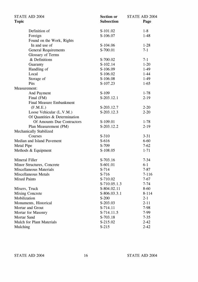
STATE AID 2004 STATE AID 2004
STATE AID 2004 STATE AID 200416
Section orTopic Subsection Page
Definition of S-101.02 1-8Foreign S-106.07 1-48Found on the Work, Rights In and use of S-104.06 1-28General Requirements S-700.01 7-1Glossary of Terms & Definitions S-700.02 7-1Guaranty S-102.14 1-20Handling of S-106.09 1-49Local S-106.02 1-44Storage of S-106.08 1-49Pits S-107.23 1-65
Measurement:And Payment S-109 1-78Final (FM) S-203.12.1 2-19Final Measure Embankment (F.M.E.) S-203.12.7 2-20Loose Vehicular (L.V.M.) S-203.12.3 2-20Of Quantities & Determination Of Amounts Due Contractors S-109.01 1-78Plan Measurement (PM) S-203.12.2 2-19
Mechanically StabilizedCourses S-310 3-31
Median and Island Pavement S-616 6-60Metal Pipe S-709 7-62Methods & Equipment S-108.05 1-71
Mineral Filler S-703.16 7-34Minor Structures, Concrete S-601.01 6-1Miscellaneous Materials S-714 7-87Miscellaneous Metals S-716 7-116Mixed Paints S-710.02 7-67
S-710.05.1.3 7-74Mixers, Truck S-804.02.11 8-60Mixing Concrete S-806.03.3.1 8-114Mobilization S-200 2-1Monuments, Historical S-203.03 2-11Mortar and Grout S-714.11 7-98Mortar for Masonry S-714.11.5 7-99Mortar Sand S-703.18 7-35Mulch for Plant Materials S-215.02 2-42Mulching S-215 2-42
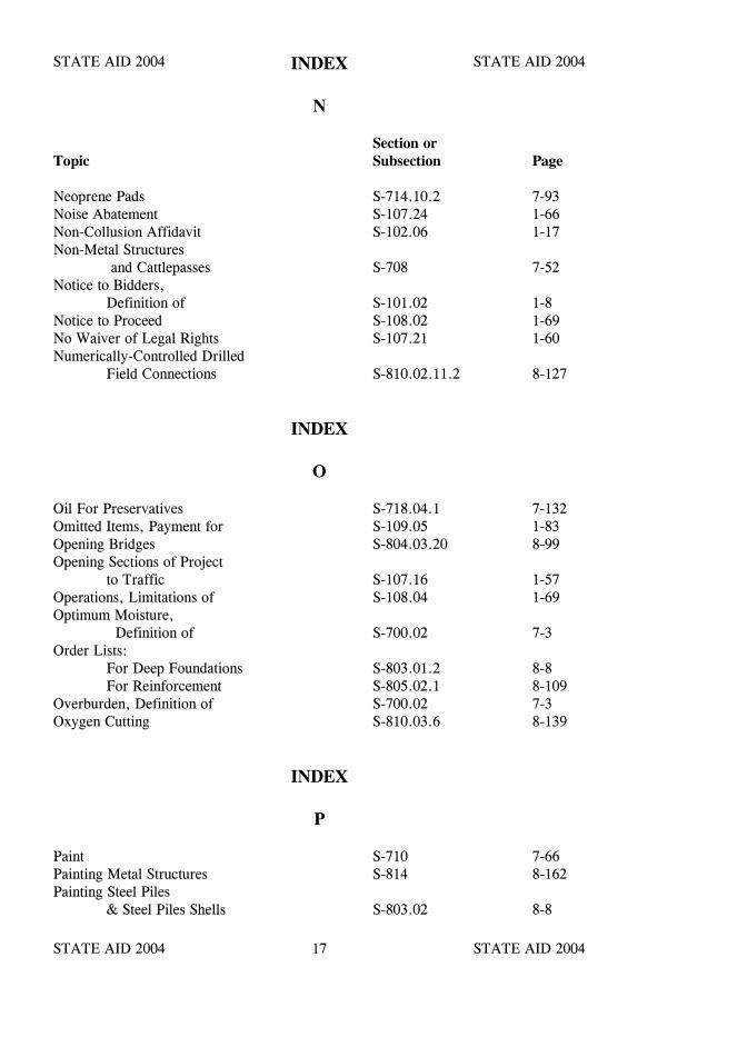
STATE AID 2004 STATE AID 2004
STATE AID 2004 STATE AID 200417
INDEX
N
Section orTopic Subsection Page
Neoprene Pads S-714.10.2 7-93Noise Abatement S-107.24 1-66Non-Collusion Affidavit S-102.06 1-17Non-Metal Structures
and Cattlepasses S-708 7-52Notice to Bidders,
Definition of S-101.02 1-8Notice to Proceed S-108.02 1-69No Waiver of Legal Rights S-107.21 1-60Numerically-Controlled Drilled
Field Connections S-810.02.11.2 8-127
INDEX
O
Oil For Preservatives S-718.04.1 7-132Omitted Items, Payment for S-109.05 1-83Opening Bridges S-804.03.20 8-99Opening Sections of Project
to Traffic S-107.16 1-57Operations, Limitations of S-108.04 1-69Optimum Moisture,
Definition of S-700.02 7-3Order Lists:
For Deep Foundations S-803.01.2 8-8For Reinforcement S-805.02.1 8-109
Overburden, Definition of S-700.02 7-3Oxygen Cutting S-810.03.6 8-139
INDEX
P
Paint S-710 7-66Painting Metal Structures S-814 8-162Painting Steel Piles
& Steel Piles Shells S-803.02 8-8
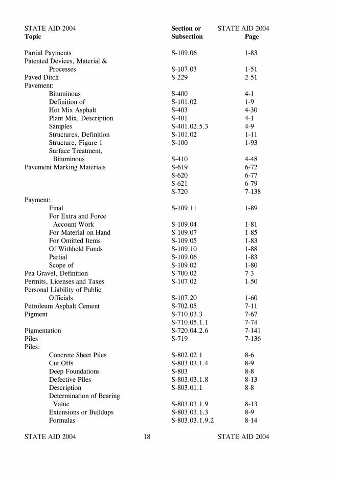
STATE AID 2004 STATE AID 2004
STATE AID 2004 STATE AID 200418
Section orTopic Subsection Page
Partial Payments S-109.06 1-83Patented Devices, Material &
Processes S-107.03 1-51Paved Ditch S-229 2-51Pavement:
Bituminous S-400 4-1Definition of S-101.02 1-9Hot Mix Asphalt S-403 4-30Plant Mix, Description S-401 4-1Samples S-401.02.5.3 4-9Structures, Definition S-101.02 1-11Structure, Figure 1 S-100 1-93Surface Treatment, Bituminous S-410 4-48
Pavement Marking Materials S-619 6-72S-620 6-77S-621 6-79S-720 7-138
Payment:Final S-109.11 1-89For Extra and Force Account Work S-109.04 1-81For Material on Hand S-109.07 1-85For Omitted Items S-109.05 1-83Of Withheld Funds S-109.10 1-88Partial S-109.06 1-83Scope of S-109.02 1-80
Pea Gravel, Definition S-700.02 7-3Permits, Licenses and Taxes S-107.02 1-50Personal Liability of Public
Officials S-107.20 1-60Petroleum Asphalt Cement S-702.05 7-11Pigment S-710.03.3 7-67
S-710.05.1.1 7-74Pigmentation S-720.04.2.6 7-141Piles S-719 7-136Piles:
Concrete Sheet Piles S-802.02.1 8-6Cut Offs S-803.03.1.4 8-9Deep Foundations S-803 8-8Defective Piles S-803.03.1.8 8-13Description S-803.01.1 8-8Determination of Bearing Value S-803.03.1.9 8-13Extensions or Buildups S-803.03.1.3 8-9Formulas S-803.03.1.9.2 8-14

STATE AID 2004 STATE AID 2004
STATE AID 2004 STATE AID 200419
Section orTopic Subsection Page
Loading Tests S-803.03.1.9.4.2.1 8-15Manufacture: Of Prestressed Concrete S-804.03.22 8-100Materials S-719 7-136Method of Driving S-803.03.1.7 8-10Order Lists for Deep Foundations S-803.01.2 8-8Pre-formed Pile Holes S-803.03.1.7.4.5 8-12Preparation for Driving S-803.03.1.6 8-10Preparation of Foundation For Footings S-801.04 8-1Pretensioning and Post- tensioning S-804.03.22 8-100Sheet Piling, Description of S-802.01 8-6Steel Sheet Piles S-719.05 7-137
S-802.02.2 8-6Storage & Handling of Prestressed Concrete S-804.03.22.6 8-105Test Piles S-803.03.1.11 8-20
Pin Clearance S-810.03.19 8-143Pin Connections S-810.03.28.12 8-150Pins and Rollers S-810.03.17 8-143Pipes:
Bedding S-603.04 6-10Bituminous Coated Corrugated Aluminum Alloy Culvert Pipe and Arches S-709.11 7-63Bituminous Coated Corrugated Metal Pipe and Pipe Arches S-709.03 7-62Bituminous Coated Corrugated Metal Pipe for Underdrains S-709.07 7-63Bituminous Coated Paved Invert Corrugated Aluminum Alloy Culvert Pipe and Arches S-709.12 7-63Bituminous Coated Paved Invert Corrugated Metal Pipe and Arches S-709.05 7-63Cast Iron Culvert Pipe S-709.01 7-62Concrete S-708.02 7-52Concrete Arch S-708.14 7-57Elliptical Concrete Culvert S-708.15 7-57Concrete Drain Tile S-708.06 7-57Concrete Pipe Cattlepass S-708.03 7-57Corrugated Aluminum Alloy Culvert Pipe & Arches S-709.09 7-63

STATE AID 2004 STATE AID 2004
STATE AID 2004 STATE AID 200420
Section orTopic Subsection Page
Corrugated Aluminum Alloy Pipe for Underdrains S-709.10 7-63Corrugated Metal Culvert Pipe & Pipe Arches S-709.02 7-62Corrugated Metal Pipe for Underdrains S-709.06 7-63Drain Tile S-708.06 7-57Galvanized S-709.02 7-62Nonreinforced Concrete Pipe S-708.02.4 7-54Perforated Plastic Pipe S-708.20 7-59Plastic Sewer Pipe and Fittings S-708.18 7-58Polymer Coated Corrugated Metal S-709.08 7-63Porous Concrete Pipe for Underdrains S-708.07 7-57Relaid S-603.07 6-14Reinforced Concrete Pipe S-708.02.5 7-54Reinforced Concrete Flared end Sections S-708.04 7-57Removed S-202.04 2-6Special Sections (Non-Metal) S-708.23 7-61Special Sections (Metal) S-709.18 7-64Underdrains S-605 6-28
Plans:Alteration of S-104.02 1-25And Working Drawings S-105.02 1-31Conformity with S-105.03 1-32Coordination of S-105.04 1-33Definition of S-101.02 1-9Examination of S-102.05 1-16Intent of S-102.05 1-16Specifications, Supple- mental Specifications, Special Provisions, Notice to Bidders, Coordination of S-105.04 1-33
Plant Inspection S-106.05 1-48Plant Mixtures, Bituminous S-400 4-1Plastic Filter Fabric S-714.13 7-104Plastic Limit (P.L.), Definition
of S-700.02 7-3Plasticity Index, Definition of S-700.02 7-3
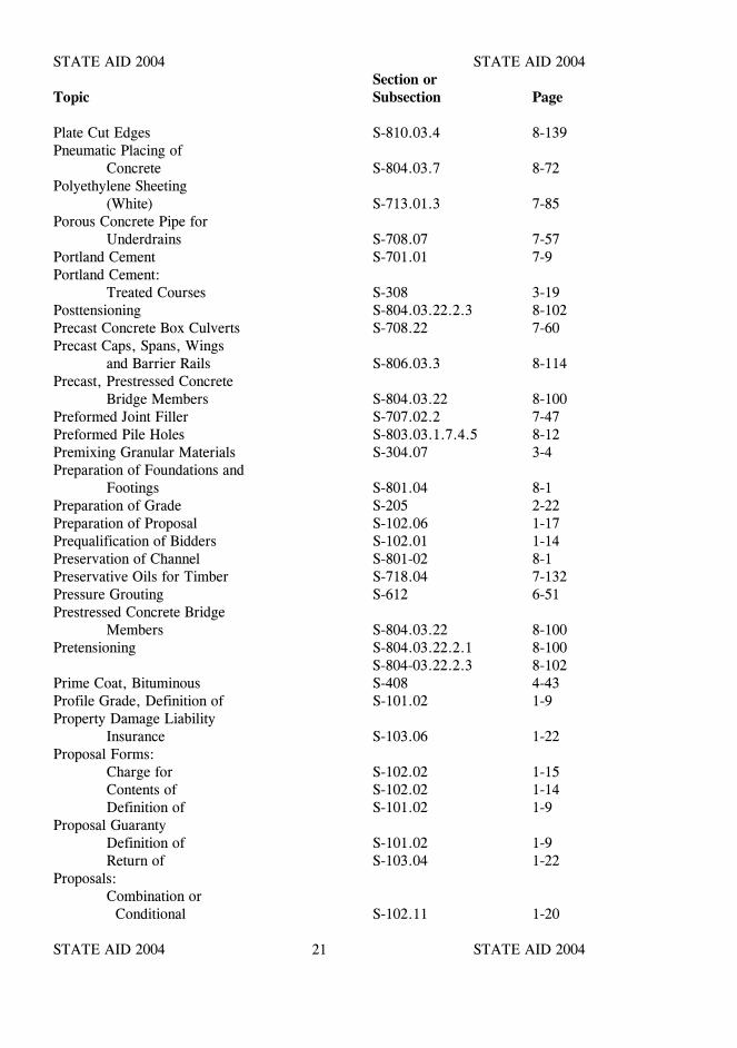
STATE AID 2004 STATE AID 2004
STATE AID 2004 STATE AID 200421
Section orTopic Subsection Page
Plate Cut Edges S-810.03.4 8-139Pneumatic Placing of
Concrete S-804.03.7 8-72Polyethylene Sheeting
(White) S-713.01.3 7-85Porous Concrete Pipe for
Underdrains S-708.07 7-57Portland Cement S-701.01 7-9Portland Cement:
Treated Courses S-308 3-19Posttensioning S-804.03.22.2.3 8-102Precast Concrete Box Culverts S-708.22 7-60Precast Caps, Spans, Wings
and Barrier Rails S-806.03.3 8-114Precast, Prestressed Concrete
Bridge Members S-804.03.22 8-100Preformed Joint Filler S-707.02.2 7-47Preformed Pile Holes S-803.03.1.7.4.5 8-12Premixing Granular Materials S-304.07 3-4Preparation of Foundations and
Footings S-801.04 8-1Preparation of Grade S-205 2-22Preparation of Proposal S-102.06 1-17Prequalification of Bidders S-102.01 1-14Preservation of Channel S-801-02 8-1Preservative Oils for Timber S-718.04 7-132Pressure Grouting S-612 6-51Prestressed Concrete Bridge
Members S-804.03.22 8-100Pretensioning S-804.03.22.2.1 8-100
S-804-03.22.2.3 8-102Prime Coat, Bituminous S-408 4-43Profile Grade, Definition of S-101.02 1-9Property Damage Liability
Insurance S-103.06 1-22Proposal Forms:
Charge for S-102.02 1-15Contents of S-102.02 1-14Definition of S-101.02 1-9
Proposal GuarantyDefinition of S-101.02 1-9Return of S-103.04 1-22
Proposals:Combination or Conditional S-102.11 1-20
STATE AID 2004 STATE AID 2004
STATE AID 2004 STATE AID 200422
Section orTopic Subsection Page
Consideration of S-103.01 1-21Contents S-102.02 1-14Definition of S-101.02 1-9Delivery of S-102.09 1-19Guaranty S-102.08 1-19Interpretation of Quantities S-102.04 1-16Irregular S-102.07 1-18Issuance of S-102.03 1-15Non-Collusion Affidavit S-102.06 1-17Preparation of S-102.06 1-17Public Opening of S-102.12 1-20Withdrawal or Revision of S-102.10 1-19
Prosecution and Progress S-108 1-68Protection and Restoration of
Property and Landscape S-107.12 1-55Public Convenience and
Safety S-107.07 1-52Public Officials, Personal
Liability of S-107.20 1-60Pumping Concrete S-803.03.2.7.3 8-39
S-804.03.8 8-73Pumping Foundations S-801.06 8-3
INDEX
Q
Quantities:Alteration of S-104.02 1-25Interpretation in Bid Schedule S-102.04 1-16Measurement of and Determination of Amounts Due Contractor S-109.01 1-78
INDEX
R
Railing S-813 8-159Railway-Highway Provisions S-107.08 1-52Railway Requirements S-107.08 1-52Raised Pavement markers S-627 6-83
STATE AID 2004 STATE AID 2004
STATE AID 2004 STATE AID 200423
Section orTopic Subsection Page
Rapid Curing CutbackAsphalt S-702.06.1 7-13
Rates, Labor, Materials andEquipment for ExtraWork S-109.04 1-81
Rates, Freight and Labor, NoAdditional Allowance for S-109.09 1-88
Reclaimed Asphalt Pavement (RAP) S-401.02.3.1 4-4Reflective Sheeting S-721.06 7-157Reflectorized Signs S-630 6-86Reinforced Concrete Pipe S-708.02.5 7-54Reinforcement S-711.01 7-78Reinforcing Steel S-711.02 7-78Reinforcement and Wire
Rope S-711 7-78Relaid Pipe S-603.07 6-14Removal of Falsework, Forms
& Housing S-601.09.3 6-2S-804.03.15 8-78
Removal of Structures andObstructions S-104.05 1-27
Removal of Unacceptable &Unauthorized Work S-105.12 1-38
Rental Rates S-109.04 1-82Responsibility for Damage
Claims S-107.14 1-57Responsibility for Work,
Contractor’s S-107.17 1-58Restoration of Surfaces
Opened by Permit S-107.04 1-51Right-of-Way, Definition of S-101.02 1-10Right-of-Way, Furnishing S-107.19 1-60Right-of-Way Markers S-617 6-64Rights In and Use of
Material Found on theWork S-104.06 1-28
Riprap:And Slope Paving S-815 8-167Concrete in Bags S-815.03.6 8-169Grouted S-815.03.4 8-169Size S-815.02 8-167Stone S-815.03.5 8-169
Roadbed, Definition of S-101.02 1-10Roadbed Reclamation S-632 6-94Roadside, Definition of S-101.02 1-10
STATE AID 2004 STATE AID 2004
STATE AID 2004 STATE AID 200424
Section orTopic Subsection Page
Roadside DevelopmentGeneral S-210 2-30Definition of S-101.02 1-10Materials S-715 7-107
Roadway, Definition of S-101.02 1-10Roadway Structure,
Definition of S-101.02 1-10Rock Excavation S-203.02.2 2-8Rolled Zinc S-716.12 7-117Rubber-Type Gaskets for
Joining Conduits S-707.04 7-49
INDEX
S
Salvage S-202.03 2-6Sample, Definition of S-700.02 7-3Samples, Tests & Cited
Specifications S-106.03 1-46Sampling and Testing S-700.03 7-5Sand, Definition of S-700.02 7-3Sand-Clay, Definition of S-700.02 7-3Sanitary Provisions S-107.06 1-52Screenings, Definition of S-700.02 7-3Scope of Payment S-109.02 1-80Scope of Work S-104 1-25Seal Coat S-410 4-48Seed S-715.03 7-109Seeding S-214 2-38Settlement by Blasting S-203.10 2-19Shale, Definition of S-700.02 7-3Shell S-703.20.2.2 7-36Sheet Piling S-802 8-6Shoulder, Definition of S-101.02 1-10Shoulders S-320 3-42Shrinkage Limit (S.L.)
Definition of S-700.02 7-3Sidewalk, Definition of S-101.02 1-10Sidewalks S-608 6-40Sieves, Definition of S-700.02 7-4Signs and Barricades S-107.10 1-53
S-630 6-86Siltation and Pollution S-107.12 1-55Silt, Definition of S-700.02 7-4
STATE AID 2004 STATE AID 2004
STATE AID 2004 STATE AID 200425
Section orTopic Subsection Page
Silt Fence S-233 2-58Slag, Definition of S-700.02 7-4Slag for Bases S-703.20.2.1 7-36Slurry Seal S-411 4-59Solid Sodding S-226 2-45Source of Supply & Quality
Requirements S-106.01 1-44Special Provisions,
Definition of S-101.02 1-10Specific Gravity,
Definition of S-700.02 7-4Specifications, Conformity With S-105.03 1-32
Definition of S-101.02 1-10Examination of S-102.05 1-16
Splicing of Reinforcement S-602.06.1 6-7Stabilization Fabric S-232 2-56Standard Density,
Definition of S-700.02 7-4Standard Operating Procedure,
Definition of S-101.02 1-11Standard Terms S-101.03 1-14State, Definition of S-101.02 1-11Steel:
Castings S-716.02 7-116Forgings S-716.03 7-116Grid Flooring S-812 8-156Identification During Fabrication S-810.03.25.2 8-145Piles S-719.04 7-137
S-803.02 8-8Post for Small Signs S-721.02.3 7-154Sheet Piling S-719.05 7-137
S-802.02.2 8-6Structural S-717 7-119 Fabrication by Numerically-Controlled Drilled Field Connections S-810.02.11.2 8-127Tightening High Strength Bolts S-810.02.20 8-131Members: Straightening Bent Material S-810.03.28.8 8-149 Cambering S-810.03.28.9 8-149Structures S-810 8-123Wire Fabric S-711.02.3 7-80
Stone Blanket Protection and

STATE AID 2004 STATE AID 2004
STATE AID 2004 STATE AID 200426
Section orTopic Subsection Page
Filter Blanket Materials S-705 7-40Structural Steel S-717 7-119Structural:
Concrete for Minor Structures S-601.01 6-1Steel S-717 7-119Timber and Lumber S-718 7-130
Structural Concrete S-601 6-1Structure Excavation for
Culverts & Minor Structures S-206 2-24
Structures, Definition of S-101.02 1-11Structures and Obstructions
Removal and Disposal of S-202 2-5Subbase Course, Definition
of S-101.02 1-11Subbases and Bases S-300 3-1Subcontractor, Definition of S-101.02 1-11Subgrade, Definition of S-101.02 1-11Subgrade, Preparation S-205 2-22Subletting of Contract S-108.01 1-68Substructure, Definition of S-101.02 1-11Superintendent, Definition of S-101.02 1-11Superstructure, Definition S-101.02 1-11Supplemental Agreement
Definition of S-101.02 1-11Supplemental Specifications,
Definition of S-101.02 1-11Surety, Definition of S-101.02 1-12Surface Treatment,
Bituminous S-410 4-48
INDEX
T
Tables:Coarse Aggregate for Cement Concrete S-703.03.2.4 7-24Composite Graduations for Mechanically Stabilized Courses S-703.08 7-31Deleterious Substances in Course Aggregate for Cement Concrete S-703.03.2.1 7-23
STATE AID 2004 STATE AID 2004
STATE AID 2004 STATE AID 200427
Section orTopic Subsection Page
Cover Aggregates for Bituminous Surface Treatments S-703.14.2.1 7-33Granular Materials for Subbases and Bases S-703.07.2 7-29Mechanically Stabilized Courses S-703.08 7-31Stabilizer Aggregate S-703.20.3 7-37Guide for Removal of False- work, Forms & Housing: Bridges S-804.03.15 8-78 Minor Structures S-601.09.3 6-2Liquidated Damages S-108.07 1-73Master Proportion Table for: Structural Concrete S-804.02.10 8-56Rates of Application of Seal Coats, Table 410-A S-410 4-56,
4-57 &4-58
Requirements for: Asphalt Cement (Petroleum), Table I S-702.12 7-17 Table II S-702.12 7-18Bituminous Materials, Specifications for prime-Table III S-702.12 7-19Surface Tolerance for Layers of Asphalt Pavement S-403.03.2 4-30Working Temperatures for-Table IV S-702.12 7-19
Tack Coat S-407 4-41Taxes S-107.02 1-50Temporary Structures,
Definition of S-101.02 1-12Temporary Suspension of
Work S-108.04.3 1-70Test Portion, Definition of S-700.02 7-4Test Result, Definition of S-700.02 7-4Test Value, Definition of S-700.02 7-4The Work, Definition of S-101.02 1-12Thinners for Paint S-710.01.1 7-66Timber and Lumber S-718 7-130Titles (or Headings),
Definitions of S-101.02 1-12
STATE AID 2004 STATE AID 2004
STATE AID 2004 STATE AID 200428
Section orTopic Subsection Page
Tolerances:Conformity S-700.04 7-5
Topsoil S-715.01 7-107Topsoiling S-211 2-31Township, Definition of S-101.02 1-12Traffic Island Pavement S-616 6-60Traffic, Maintenance of S-104.04 1-26
Detail Stripe S-619.06 6-74Traffic Markings, Painted S-619 6-72Traveled Way, Definition of S-101.02 1-12Treatment, Preservation Oils
for Timber S-718.04 7-132Trench, Imperfect S-603.10 6-15Truck Mixers and Truck
Agitators S-804.03.6.1 8-68Turn of the Nut Tightening S-810.03.1.4 8-135
INDEX
U
Unacceptable and Un-authorized Work, Removal of S-105.12 1-38
Unacceptable Materials S-106.10 1-49Unclassified Excavation S-203.02.1 2-8Underdrains S-605 6-28Use of Explosives S-107.11 1-55Utilities, Cooperation with S-105.06 1-34Utilities, Responsibility for S-107.18 1-59
INDEX
V
Value Engineering Incentive S-104.08 1-29Volume Change, Definition Of S-700.02 7-4
STATE AID 2004 STATE AID 2004
STATE AID 2004 STATE AID 200429
INDEX
W
Section orTopic Subsection Page
Warning Signs S-107.10 1-53 S-630 6-86
Water S-714.01 7-87Water-Cement Ratio,
Definition of S-700.02 7-4Welders, Qualification for S-810.03.5 8-139Welding S-812.02.3 8-156Wire Rope or Wire Cable
for Prestressed Concrete S-711 7-78Work:
Acceptance of S-105.16 1-40Character of S-104.02 1-25Control of S-105 1-31Extra S-109.04 1-81Failure to Complete on Time S-108.07 1-73Inspection of S-105.11 1-38Order, Definition of S-101.02 1-12Removal of Unacceptable& Unauthorized S-105.12 1-38Scope of S-104 1-25Temporary Suspension of S-108.04.3 1-70The, Definition of S-101.02 1-12
Working Day, Definition of S-101.02 1-12Working Drawings,
Definitions of S-101.02 1-13Working Temperature for
Bituminous MaterialsTable IV S-702.12 7-19
Workmen, Character of S-108.05 1-71

STATE AID 2004 STATE AID 2004
STATE AID 2004 STATE AID 2004

STATE AID 2004 STATE AID 2004
STATE AID 2004 STATE AID 2004

STATE AID 2004 STATE AID 2004
STATE AID 2004 STATE AID 2004
STATE AID 2004 STATE AID 2004
STATE AID 2004 STATE AID 2004
STA
TE
AID
- 2004


![Welcome [] U.S. 52/IL 64 OVER THE MISSISSIPPI RIVER U.S. 52/IL 64 OVER THE MISSISSIPPI RIVER. ... Proposed Tied-Arch Bridge. U.S. 52/IL 64 OVER THE MISSISSIPPI RIVER](https://static.fdocuments.in/doc/165x107/5ad6b5807f8b9a98098be348/welcome-us-52il-64-over-the-mississippi-river-us-52il-64-over-the-mississippi.jpg)