
miniCMTS200a Setup Notes v1 - ATV Research
24
Copyright © 2014 Pico DIgital Inc. All rights reserved This Document is Pico Digital proprietary and confidential not to be reproduced, used, sold or in any other way exploited or transferred to any third party without the prior written permission of Pico Digital. miniCMTS200a Setup Notes Application Note Pico Digital Inc. www.picodigital.com 18 December 2015 v1.3
Transcript of miniCMTS200a Setup Notes v1 - ATV Research
Copyright © 2014 Pico DIgital Inc. All rights reserved This Document is Pico Digital proprietary and confidential not to be reproduced, used, sold or in any other way exploited or transferred to any third party without the prior written permission of Pico Digital.
miniCMTS200a Setup Notes Application Note
Pico Digital Inc.
www.picodigital.com 18 December 2015 v1.3
miniCMTS200a Setup Notes v1.3
Application Note Page 1 of 23
Copyright © 2014 Pico Digital Inc. All rights reserved This Document is Pico Digital proprietary and confidential not to be reproduced, used, sold or in any other way exploited or transferred to any third party without the prior written permission of Pico Digital.
Revision History
Rev # Date Author Reason
0.8 10/01/14 R. Fajarit Initial Preliminary Release
0.9 10/16/14 R. Fajarit FAQ Addition, minor edits
0.95 02/13/14 R. Fajarit FAQ Addition, edits
1.0 03/10/15 R. Fajarit FAQ Additions
1.1 10/29/15 R. Fajarit FAQ Additions
1.2 11/11/15 R. Fajarit Trouble Shooting – Using the Snooping page
1.3 12/17/15 R. Fajarit FAQ Additions – DHCP/TFTP, Pubic IP Remote
Table 1: Revision History
Proprietary Notice
The information contained herein is property of Pico Digital Inc., or third party proprietary information
which Pico Digital Inc. is obliged to protect and shall not be disclosed in whole or in part without the
prior written permission of Pico Digital Inc. or the appropriate third party. Discussions contained in this
document are covered under NDA with PICO Digital Inc.

miniCMTS200a Setup Notes v1.3
Application Note Page 2 of 23
Copyright © 2014 Pico Digital Inc. All rights reserved This Document is Pico Digital proprietary and confidential not to be reproduced, used, sold or in any other way exploited or transferred to any third party without the prior written permission of Pico Digital.
Table of Contents
1 miniCMTS200a Quick Setup .................................................................................................................. 4
1.1 Introduction .................................................................................................................................. 4
1.2 Overview ....................................................................................................................................... 4
1.3 Equipment List .............................................................................................................................. 5
1.4 Down Channel and Up Channel Configuration Files ..................................................................... 6
1.5 Updating the unit .......................................................................................................................... 6
1.6 User manual .................................................................................................................................. 6
2 Basic setup ............................................................................................................................................ 8
2.1 Network Setup .............................................................................................................................. 8
2.2 Down Channel Configuration ........................................................................................................ 9
2.3 Up Channel Configuration ............................................................................................................. 9
2.4 Shared Secret – CM and CMTS connection ................................................................................. 10
2.5 Start Page – CM online Status ..................................................................................................... 13
3 Troubleshooting Tips .......................................................................................................................... 15
3.1 Common Issues ........................................................................................................................... 15
3.2 Snooping Page example – Checking RF connections .................................................................. 16
3.3 Flow Encoding ............................................................................................................................. 18
3.4 FAQ - Frequency Ask Questions .................................................................................................. 19
Table of Figures
Figure 1: Management IP Setup ................................................................................................................... 8
Figure 2: Down Channel Setup ..................................................................................................................... 9
Figure 3: Up Channel Setup ....................................................................................................................... 10
Figure 4: Shared Secret .............................................................................................................................. 11
Figure 5: CM Config file edit - Selecting Shared Secret .............................................................................. 12
Figure 6: CM Config File Edit – Entered Shared Secret Value must match CMTS value ............................ 12
Figure 7: Start Page – Overview of CM Status ........................................................................................... 13
Figure 8: Start Page CM Status Section ...................................................................................................... 13
Figure 9: Cable Modems Online ................................................................................................................. 14
Figure 10: Cable Modems Offline .............................................................................................................. 15

miniCMTS200a Setup Notes v1.3
Application Note Page 3 of 23
Copyright © 2014 Pico Digital Inc. All rights reserved This Document is Pico Digital proprietary and confidential not to be reproduced, used, sold or in any other way exploited or transferred to any third party without the prior written permission of Pico Digital.
Figure 11: Snooping output If RF connections are not properly connected .............................................. 16
Figure 12: Cable Modems are Discovered. Currently no DHCP is configured ........................................... 16
Figure 13: CMs starting to receive IP addresses ....................................................................................... 17
Figure 14: Cable Modems receiving IP addresses ...................................................................................... 17
Table of Tables
Table 1: Revision History ............................................................................................................................. 1
Table 2: miniCMTS200a Equipment List ..................................................................................................... 5
miniCMTS200a Setup Notes v1.3
Application Note Page 4 of 23
Copyright © 2014 Pico Digital Inc. All rights reserved This Document is Pico Digital proprietary and confidential not to be reproduced, used, sold or in any other way exploited or transferred to any third party without the prior written permission of Pico Digital.
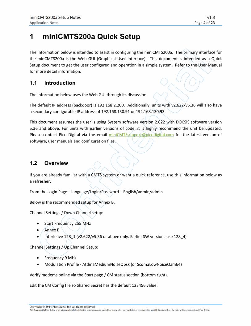
1 miniCMTS200a Quick Setup
The information below is intended to assist in configuring the miniCMTS200a. The primary interface for
the minCMTS200a is the Web GUI (Graphical User Interface). This document is intended as a Quick
Setup document to get the user configured and operation in a simple system. Refer to the User Manual
for more detail information.
1.1 Introduction
The information below uses the Web GUI through its discussion.
The default IP address (backdoor) is 192.168.2.200. Additionally, units with v2.622/v5.36 will also have
a secondary configurable IP address of 192.168.130.91 or 192.168.130.93.
This document assumes the user is using System software version 2.622 with DOCSIS software version
5.36 and above. For units with earlier versions of code, it is highly recommend the unit be updated.
Please contact Pico Digital via the email [email protected] for the latest version of
software, user manuals and configuration files.
1.2 Overview
If you are already familiar with a CMTS system or want a quick reference, use this information below as
a refresher.
From the Login Page - Language/Login/Password – English/admin/admin
Below is the recommended setup for Annex B.
Channel Settings / Down Channel setup:
• Start Frequency 255 MHz
• Annex B
• Interleave 128_1 (v2.622/v5.36 or above only. Earlier SW versions use 128_4)
Channel Settings / Up Channel Setup:
• Frequency 9 MHz
• Modulation Profile - AtdmaMediumNoiseQpsk (or ScdmaLowNoiseQam64)
Verify modems online via the Start page / CM status section (bottom right).
Edit the CM Config file so Shared Secret has the default 123456 value.

miniCMTS200a Setup Notes v1.3
Application Note Page 5 of 23
Copyright © 2014 Pico Digital Inc. All rights reserved This Document is Pico Digital proprietary and confidential not to be reproduced, used, sold or in any other way exploited or transferred to any third party without the prior written permission of Pico Digital.
1.3 Equipment List
The following equipment list summarizes a baseline CMTS setup. The optional equipment is not required
for the base setup, but provided as a reference for other Pico Digital Products that is compatible with
the miniCMTS200a.
The following is an example for ‘hard wiring’ the miniCMTS200a (CMTS).
• CMTS (Ethernet) � PC and/or DHCP server (via 192.168.2.200 – initial setup only)
• CMTS (RF Uplink and RF Downlink connectors) � 2 to 1 splitter � Cable Modems (Shared
Secret 123456)
• DHCP Server (Ethernet) � CMTS, PC, and modems and optional equipment
Note: Attenuating the signal. If the cabling is short, it is recommended that the signal be
attenuated. Recommend 30 to 40 dBm attenuation as a starting point.
miniCMTS200a Equipment List
Title Description Quantity Notes
CMTS miniCMTS200A 1 CMTS unit
DHCP Server Assign IP address to
modems
1 Condor DHCP Server
Optional
RF 2 to 1
Splitter
(diplexer)
Combine Uplink and
Downlink RF output to 1
splitter
1 Single output for
distribution to modems
PC Connector to DHCP Server
or directly to CMTS
1 Web Browser Software
recommended for initial
setup
1Gbit Switch Communication and data
transfer
1 or more 1 Gigibit per port, CAT5E or
CAT6 Ethernet Cables.
Cable Modem DOCSIS 2.0, DOCSIS 3.0
(recommended)
250 D3.0
max
400 CM maximum however
only 250 CM D3.0 Max.
Smartbox Satellite media to be
distributed
1 Optional
2PD1000 Encoder with IP option 1 Optional
Condor EPG and CAS system 1 Optional
Table 2: miniCMTS200a Equipment List
miniCMTS200a Setup Notes v1.3
Application Note Page 6 of 23
Copyright © 2014 Pico Digital Inc. All rights reserved This Document is Pico Digital proprietary and confidential not to be reproduced, used, sold or in any other way exploited or transferred to any third party without the prior written permission of Pico Digital.
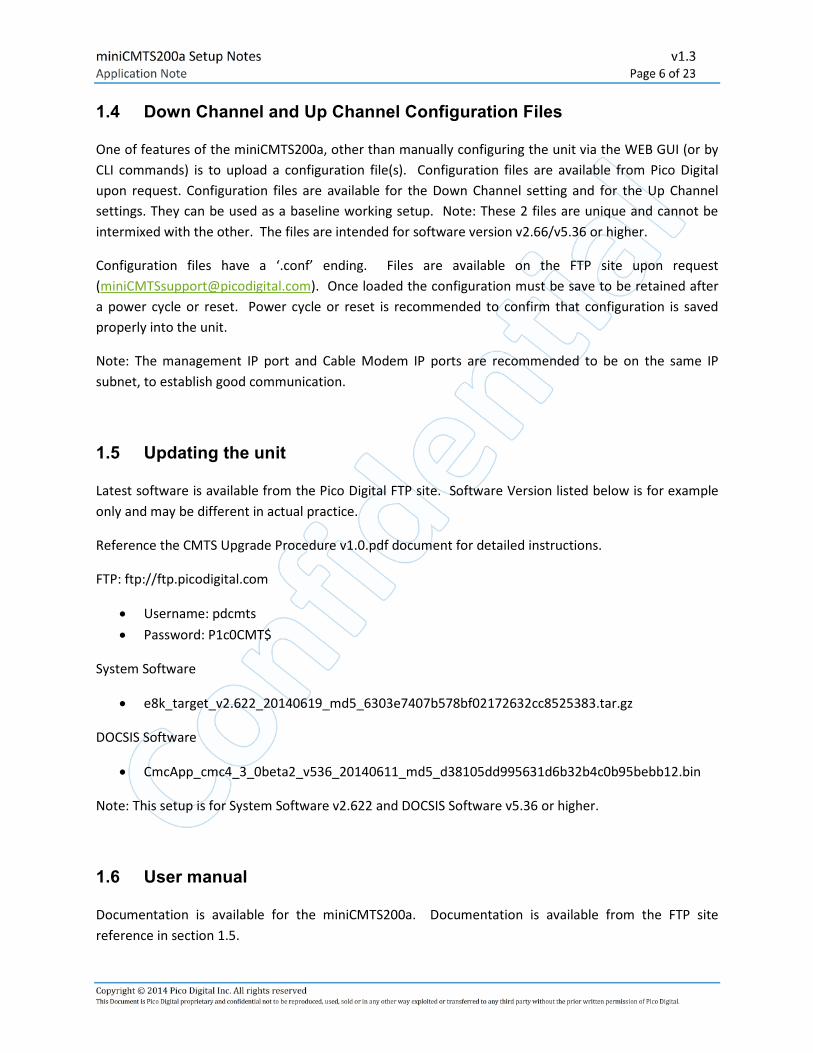
1.4 Down Channel and Up Channel Configuration Files
One of features of the miniCMTS200a, other than manually configuring the unit via the WEB GUI (or by
CLI commands) is to upload a configuration file(s). Configuration files are available from Pico Digital
upon request. Configuration files are available for the Down Channel setting and for the Up Channel
settings. They can be used as a baseline working setup. Note: These 2 files are unique and cannot be
intermixed with the other. The files are intended for software version v2.66/v5.36 or higher.
Configuration files have a ‘.conf’ ending. Files are available on the FTP site upon request
([email protected]). Once loaded the configuration must be save to be retained after
a power cycle or reset. Power cycle or reset is recommended to confirm that configuration is saved
properly into the unit.
Note: The management IP port and Cable Modem IP ports are recommended to be on the same IP
subnet, to establish good communication.
1.5 Updating the unit
Latest software is available from the Pico Digital FTP site. Software Version listed below is for example
only and may be different in actual practice.
Reference the CMTS Upgrade Procedure v1.0.pdf document for detailed instructions.
FTP: ftp://ftp.picodigital.com
• Username: pdcmts
• Password: P1c0CMT$
System Software
• e8k_target_v2.622_20140619_md5_6303e7407b578bf02172632cc8525383.tar.gz
DOCSIS Software
• CmcApp_cmc4_3_0beta2_v536_20140611_md5_d38105dd995631d6b32b4c0b95bebb12.bin
Note: This setup is for System Software v2.622 and DOCSIS Software v5.36 or higher.
1.6 User manual
Documentation is available for the miniCMTS200a. Documentation is available from the FTP site
reference in section 1.5.

miniCMTS200a Setup Notes v1.3
Application Note Page 7 of 23
Copyright © 2014 Pico Digital Inc. All rights reserved This Document is Pico Digital proprietary and confidential not to be reproduced, used, sold or in any other way exploited or transferred to any third party without the prior written permission of Pico Digital.
• miniCMTS200a-UserManual – Primary Manual for the Web GUI interface.

miniCMTS200a Setup Notes v1.3
Application Note Page 8 of 23
Copyright © 2014 Pico Digital Inc. All rights reserved This Document is Pico Digital proprietary and confidential not to be reproduced, used, sold or in any other way exploited or transferred to any third party without the prior written permission of Pico Digital.
2 Basic setup
The following is a more expanded example of basic functional setup. The following web pages is where
most of the configuration takes place.
• Network Settings / Manage IP
• Channel Settings / Down Channel
• Channel Setting / Up Channel
• Termination Management/ Shared Secret
• Start Page / CM Status (bottom right)
2.1 Network Setup
There are two network settings with the miniCMTS200a. The Backdoor IP address and the Management
IP address. The Backdoor IP address is intended for initial setup and if the user forgets the Management
port. It is not configurable and the IP address is 192.168.2.200.
The Management IP address is recommended to be configured and used for the CMTS application.
It can be configured in the Network Settings/ Manage IP Web interface section.
Figure 1: Management IP Setup

miniCMTS200a Setup Notes v1.3
Application Note Page 9 of 23
Copyright © 2014 Pico Digital Inc. All rights reserved This Document is Pico Digital proprietary and confidential not to be reproduced, used, sold or in any other way exploited or transferred to any third party without the prior written permission of Pico Digital.
2.2 Down Channel Configuration
The Down Channel setup is located in the Channel Settings / Down Channel section of the CMTS web
page. The recommended basic Down Channel Configuration for Annex B is shown in the figure below.
Click on the number and enter the appropriate change. Note the red triangles (dog ear) will appears
across a column indicating that a change has been entered and awaits confirmation. Select the ‘Save’
button icon to apply the changes to the CMTS.
Figure 2: Down Channel Setup
2.3 Up Channel Configuration
The Up Channel setup is located in the Channel Settings / Up Channel section of the CMTS web page.
The recommended basic Up Channel Configuration for Annex B is shown in the figure below. Click on the
number and enter the appropriate change. Note the red triangles (dog ear) will appears across a
column indicating that a change has been entered and awaits confirmation. Select the ‘Save’ button
icon to apply the changes to the CMTS.

miniCMTS200a Setup Notes v1.3
Application Note Page 10 of 23
Copyright © 2014 Pico Digital Inc. All rights reserved This Document is Pico Digital proprietary and confidential not to be reproduced, used, sold or in any other way exploited or transferred to any third party without the prior written permission of Pico Digital.
Figure 3: Up Channel Setup
2.4 Shared Secret – CM and CMTS connection
Communication between the Cable Modems (CM) and the miniCMTS200a will require a CM config file
and a ‘key’ otherwise known as a Shared Secret code.
The default value is 123456.
On the miniCMTS200a the ‘key’ can be determined and/or configured in the Terminal Management /
Shared Secret Web Page.

miniCMTS200a Setup Notes v1.3
Application Note Page 11 of 23
Copyright © 2014 Pico Digital Inc. All rights reserved This Document is Pico Digital proprietary and confidential not to be reproduced, used, sold or in any other way exploited or transferred to any third party without the prior written permission of Pico Digital.
Figure 4: Shared Secret
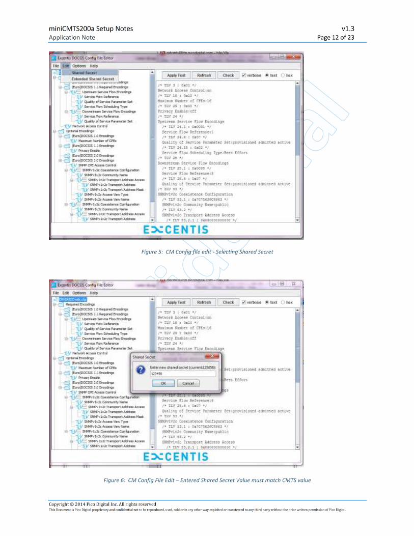
A CM configuration file must match the same Shared Secret number (123456) on the miniCMTS200a.
The example below uses the Excentis Editor to edit the Shared Secret number on the CM configuration
file. The Editor can be found at this link.
https://www.excentis.com/products/configfileeditor
Once installed
1. Go to the Edit/Shared Secret and select.
2. A pop up window will appear
3. Enter the Shared Secret value of 123456
4. Save the changes
5. Place the CM configuration file on a designated server.
miniCMTS200a Setup Notes v1.3
Application Note Page 12 of 23
Copyright © 2014 Pico Digital Inc. All rights reserved This Document is Pico Digital proprietary and confidential not to be reproduced, used, sold or in any other way exploited or transferred to any third party without the prior written permission of Pico Digital.
Figure 5: CM Config file edit - Selecting Shared Secret
Figure 6: CM Config File Edit – Entered Shared Secret Value must match CMTS value

miniCMTS200a Setup Notes v1.3
Application Note Page 13 of 23
Copyright © 2014 Pico Digital Inc. All rights reserved This Document is Pico Digital proprietary and confidential not to be reproduced, used, sold or in any other way exploited or transferred to any third party without the prior written permission of Pico Digital.
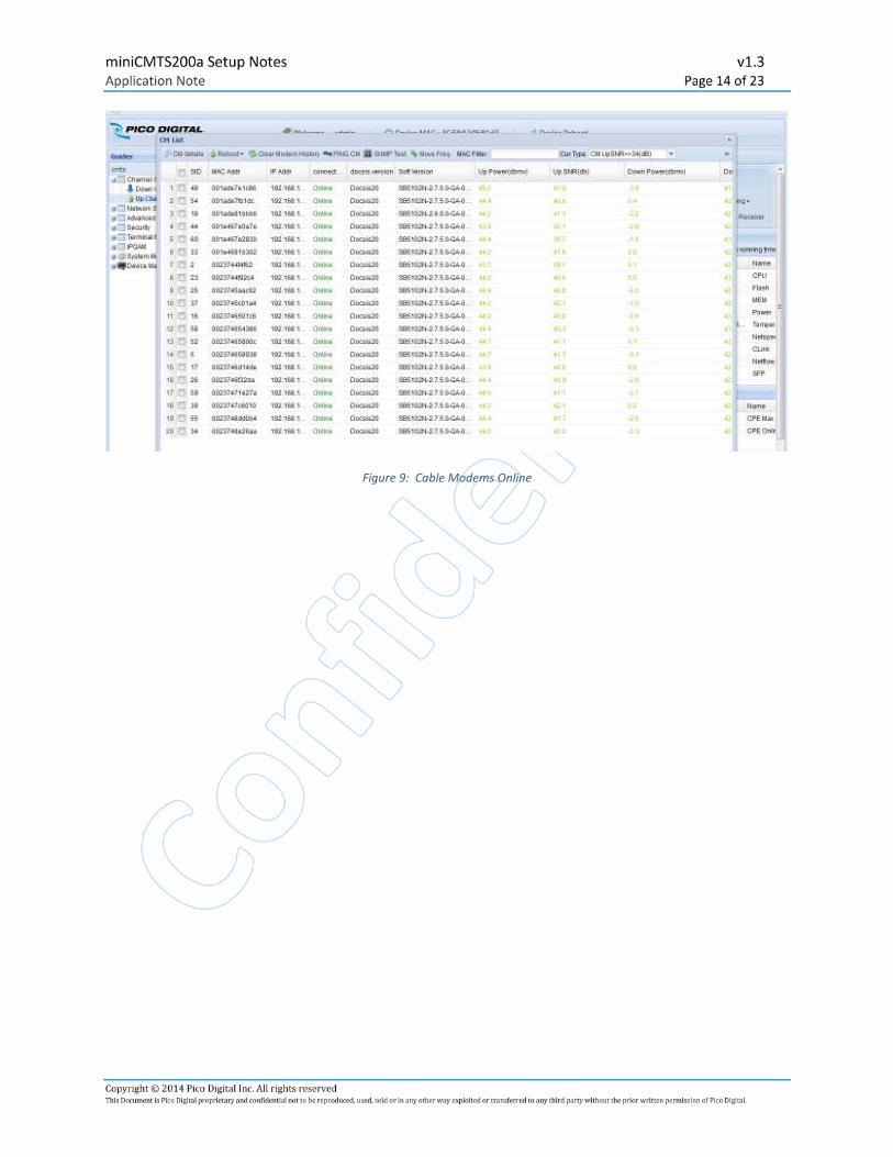
2.5 Start Page – CM online Status
Figure 7: Start Page – Overview of CM Status
Figure 8: Start Page CM Status Section
miniCMTS200a Setup Notes v1.3
Application Note Page 14 of 23
Copyright © 2014 Pico Digital Inc. All rights reserved This Document is Pico Digital proprietary and confidential not to be reproduced, used, sold or in any other way exploited or transferred to any third party without the prior written permission of Pico Digital.
Figure 9: Cable Modems Online

miniCMTS200a Setup Notes v1.3
Application Note Page 15 of 23
Copyright © 2014 Pico Digital Inc. All rights reserved This Document is Pico Digital proprietary and confidential not to be reproduced, used, sold or in any other way exploited or transferred to any third party without the prior written permission of Pico Digital.
3 Troubleshooting Tips
The following are some troubleshooting tips in setting up your system. Prior experience with CMTS
systems or advance network configuration is assumed.
Figure 10: Cable Modems Offline
3.1 Common Issues
There are many considerations when setting up the CMTS top consider.
• Frequencies greater than 99 MHz is recommended for initially testing the operation with the
cable modems.
• Signal Strength output is too strong for the Cable Modems if cable length is short. Recommend
attenuating the RF signal (at least 30 to 40 dbm).
• Setting up shared secret (matching CMTS code with CM config file) to complete CM
communication (bringing the CMs online).
• Download Channel Interleave configuration – Earlier versions of code is 128_4. Version 2.66 and
above uses interleave 128_1 for Annex B.
• Control (Management) Ethernet communication and CM (data) communication needs to be in
the same network for good Upload and Download Sync.
• DOCSIS 1.1 may require flow encoding.
miniCMTS200a Setup Notes v1.3
Application Note Page 16 of 23
Copyright © 2014 Pico Digital Inc. All rights reserved This Document is Pico Digital proprietary and confidential not to be reproduced, used, sold or in any other way exploited or transferred to any third party without the prior written permission of Pico Digital.
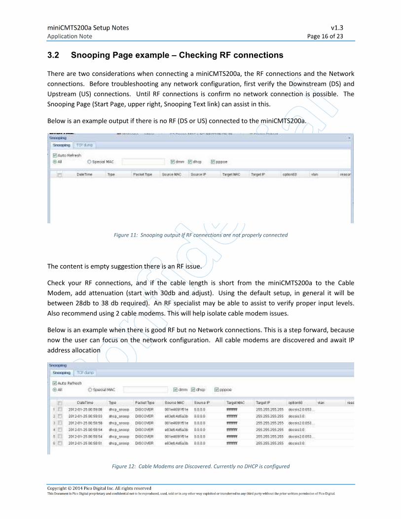
3.2 Snooping Page example – Checking RF connections
There are two considerations when connecting a miniCMTS200a, the RF connections and the Network
connections. Before troubleshooting any network configuration, first verify the Downstream (DS) and
Upstream (US) connections. Until RF connections is confirm no network connection is possible. The
Snooping Page (Start Page, upper right, Snooping Text link) can assist in this.
Below is an example output if there is no RF (DS or US) connected to the miniCMTS200a.
Figure 11: Snooping output If RF connections are not properly connected
The content is empty suggestion there is an RF issue.
Check your RF connections, and if the cable length is short from the miniCMTS200a to the Cable
Modem, add attenuation (start with 30db and adjust). Using the default setup, in general it will be
between 28db to 38 db required). An RF specialist may be able to assist to verify proper input levels.
Also recommend using 2 cable modems. This will help isolate cable modem issues.
Below is an example when there is good RF but no Network connections. This is a step forward, because
now the user can focus on the network configuration. All cable modems are discovered and await IP
address allocation
Figure 12: Cable Modems are Discovered. Currently no DHCP is configured

miniCMTS200a Setup Notes v1.3
Application Note Page 17 of 23
Copyright © 2014 Pico Digital Inc. All rights reserved This Document is Pico Digital proprietary and confidential not to be reproduced, used, sold or in any other way exploited or transferred to any third party without the prior written permission of Pico Digital.
Below is an example of the cable modems and miniCMTS200a communication where
discover/offer/request/acknowledge process is in full operation. This is the output prior to receiving IP
addresses from the DHCP server. This confirms that the network connections are working as expected.
Figure 13: CMs starting to receive IP addresses
Lastly, the cable modems are receiving IP addresses.
Figure 14: Cable Modems receiving IP addresses

miniCMTS200a Setup Notes v1.3
Application Note Page 18 of 23
Copyright © 2014 Pico Digital Inc. All rights reserved This Document is Pico Digital proprietary and confidential not to be reproduced, used, sold or in any other way exploited or transferred to any third party without the prior written permission of Pico Digital.
3.3 Flow Encoding
Below is an example of flow encoding (optional setup).
Note: Editing a CM file for Flow encoding using Excentis
Make a copy of the config file and open it with Excentis
(https://www.excentis.com/products/configfileeditor)
a) Upstream Service Flow Encoding
b) Downstream Service Flow Encoding.
Before Editing enter Share Secret Value '123456' under the Edit menu (This is the same value located on
the miniCMTS200a Termination Management /Shared Secret page. Both values need to match.)
Under the Upstream Service Flow Encoding,
• Right Click on the text.
• A Pop up window will open. Select Add.
• The Add option will give you a menu, select the Arrow button to view the 'drop down' menu.
• Once the arrow is selected you will be given several options. Chose an option. Example:
Selecting 'Upstream Peak Traffic Rate will place this option under the 'Upstream Service Flow
Encoding' Section.
• Click on text of the select option above and enter the rate you want (in this case 320000, then
select the Apply button.
Under The Downstream Service Flow Encoding
• Right Click on the text.
• A Pop up window will open. Select Add.
• The Add option will give you a menu, select the Arrow button to view the 'drop down' menu.
• Once the arrow is selected you will be given several options. Chose an option. Example:
Selecting 'Downstream Maximum Sustained Traffic Rate' will place this option under the
Downstream Service Flow Encoding' Section. (note Downstream Peak Traffic Rate option is also
available as well as several other configurable)
• Click on text of the select option above and enter the rate you want (in this case 4500000, then
select the Apply button.
Save a copy of the file when finish. There are several options to choose. Feel free to try different ones
to see which one meets your needs.
miniCMTS200a Setup Notes v1.3
Application Note Page 19 of 23
Copyright © 2014 Pico Digital Inc. All rights reserved This Document is Pico Digital proprietary and confidential not to be reproduced, used, sold or in any other way exploited or transferred to any third party without the prior written permission of Pico Digital.
3.4 FAQ - Frequency Ask Questions
1. What is the quickest way to get Cable Modems online? The miniCMTS200a is shipped already
configured for an Annex B setup. So…. it is possible to get Cable Modems online without making
any changes to the miniCMTS200a. This is referred to as a basic setup. This is highly
recommended to perform this test first to familiarize oneself with the miniCMTS200a before
moving on to a custom setup.
a) Set up the DHCP on the 192.168.130.x network. The miniCMTS200a fixed management IP
address is 192.168.130.93.
b) Place the Pico’s CM Config file from Pico’s FTP site (after confirming Share Secret is 123456)
into the DHCP/TFTP directory location
c) Reference the CM Config file on the DHCP server
d) For short cable length from miniCMTS200a to Cable Modems) (3 meters or less) recommend
starting with 30db attenuation.
e) Hardware setup – DHCP/TFTP server � Switch �miniCMTS200a �diplexer �attenuators
(optional)�Cable Modems. Apply power and check results.
f) See Setup Notes above for more details.
2. Is the CMTS a bridge or router? It is a bridge. Limit the communication within the same network
and/or provided an external router.
3. Do you have a sample of DHCP Server file and a TFTP file? Yes, this is available from Pico Digital
FTP site.
4. How are Cable Modems with 8 Downstream Channels Load balanced? They are eventually
distributed to the 16 channels or user enabled Downstream Channels.
5. How does the internal DHCP/TFTP server work (v3.76 or higher)? The DHCP/TFTP server is a
basic server which is useful for general tests and supplementing an existing Provisional DHCP
server system. It provides IP addresses and config files to the CMs. It does not, however provide
IP addresses to the CPEs, which require access to the external network gateway, resulting in the
requirement of an external Provisional DHCP Server. Any network functions that are not
included in setup for the internal DHCP/TFTP sever is intended for the external Provisional DHCP
Server.
6. After a software update the browser shows zero CMs online. Why? After an update, the system
will reboot requiring the user to re-login. Depending on browser in use, this may require the
user to refresh the window and then re-login, otherwise the 'old' browser window will display
'outdated' incorrect information.
7. How can I confirm that the Cable Modems can be ‘seen’ by the miniCMTS? On the Start page,
top right is the SNOOP text link. Select SNOOP link. IF the Cable Modems are connected
correctly, ‘DISCOVER’ text info will be display (regardless if DHCP/ TFTP server is connected). IF
not, then there is an RF link problem that needs to be resolve. Review attenuation, if applicable
and/or change to a different Cable Modem for comparison.
8. For remote technical support, how do I setup a Public IP address? To setup a public IP remote
access, do the following:

miniCMTS200a Setup Notes v1.3
Application Note Page 20 of 23
Copyright © 2014 Pico Digital Inc. All rights reserved This Document is Pico Digital proprietary and confidential not to be reproduced, used, sold or in any other way exploited or transferred to any third party without the prior written permission of Pico Digital.
a. Obtain a static public IP address assignment from your ISP and subsequently the IANA.
b. Setup on router ---> 'port forward' which tells the router to forward any incoming traffic
on a specific port to the one internal
IP address (via NAT) and to the miniCMTS. Recommend to check Router Manual for
'Port Forward' details.
c. Configure access for Port 80 (HTTP) and Port 22 (SSH).
d. Recommend checking with an IT specialist for specific details.
9. Does the CMTS support CLI? Yes. This is available from the Pico Digital FTP site. The GUI
interface is recommended as the primary interface for ease of initial configuration monitoring.
The CLI manual is available from the FTP site.
10. Why is my configuration not retained after loading a config file? Loading the config files is a 3
step process (Start Upload, Start Loading, Save). If the Save button is not selected, any reset to
the system will revert back to the previous configuration.
11. How can I save the entire configuration? There is more than one config save option available.
The 'global' config save option is on the Start Page (upper rights side), under the word 'Config'.
Upon selection, a drop down menu will appear. Select 'Export Configs' and save the file.
To load the 'global' config file, go to the same menu and Select 'Import Config (cover)'.
12. The CMTS Multicast bandwidth usage varies and appears to work fine, however if the
bandwidth usage is high, we have notice pixelization on the output. At low bandwidth the video
appears fine. What could cause this? It is possible that the switch in use, cannot handle the
larger packet sizes. In selecting a switch, verify it is 1 GigiBIt switch per port and each port can
handles that much traffic at the same time. Recommend the Alcatel - Lucent Omni Switch 6450
for high bandwidth usage.
13. What is the sequence of events in communicating with the Cable Modems? The web interface
only allows the operator to change what the miniCMTS does, like what channel it’s on etc.
The sequence of events is as follows:
e. The CM scans for the QAM channel and gets the information on where to transmit
f. The CMTS eventually acknowledges the CM requests and two way communications is
established.
g. The CM asks for an IP Address (via DHCP) from the provisioning server - this is based on
the MAC address.
h. The DHCP message contains a configuration file and location where to get it, the CM
downloads this from a TFTP server, and the file tells the CM what to do.
i. The CM sends some ‘magic’ numbers to the CMTS which are based on what is in the
configuration file, the CMTS then authorises the CM (this is called registration).
14. The CPE List (Online) shows one of the two IP address. What seems to be the problem? Most
likely the issue is the DHCP server configuration. Review the configuration and if needed,
compare the configuration with the DHCP server example from the FTP site.
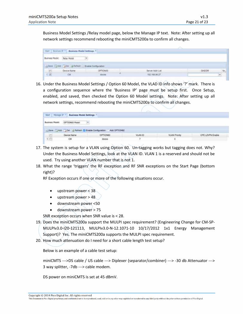
15. Under the Business Model Settings / Relay Model Section, the GIADDR does not show up in the
pull down? Only option is “Manage IP”? There is a configuration sequence where the 'Business
IP' page must be setup first. Once setup, enabled, and saved, the GIADDR will appear on the
miniCMTS200a Setup Notes v1.3
Application Note Page 21 of 23
Copyright © 2014 Pico Digital Inc. All rights reserved This Document is Pico Digital proprietary and confidential not to be reproduced, used, sold or in any other way exploited or transferred to any third party without the prior written permission of Pico Digital.
Business Model Settings /Relay model page, below the Manage IP text. Note: After setting up all
network settings recommend rebooting the miniCMTS200a to confirm all changes.
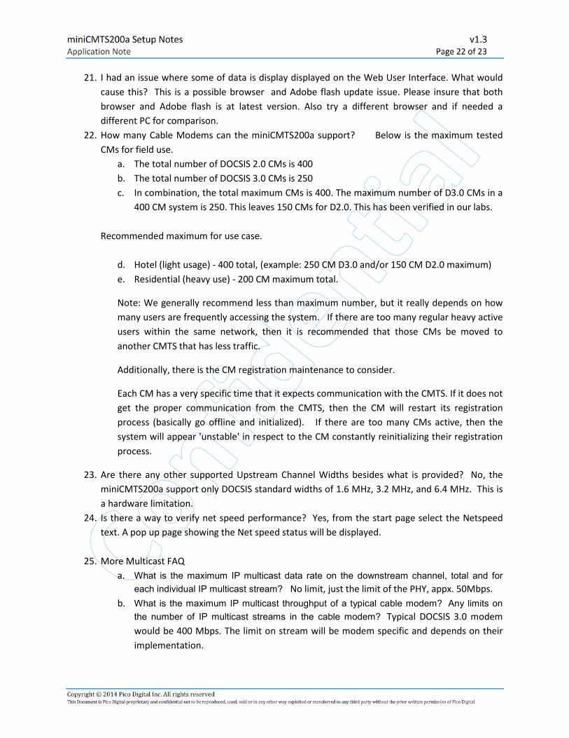
16. Under the Business Model Settings / Option 60 Model, the VLAD ID info shows ‘?’ mark. There is
a configuration sequence where the ‘Business IP’ page must be setup first. Once Setup,
enabled, and saved, then checked the Option 60 Model settings. Note: After setting up all
network settings, recommend rebooting the miniCMTS200a to confirm all changes.
17. The system is setup for a VLAN using Option 60. Un-tagging works but tagging does not. Why?
Under the Business Model Settings, look at the VLAN ID. VLAN 1 is a reserved and should not be
used. Try using another VLAN number that is not 1.
18. What the range ‘triggers’ the RF exception and RF SNR exceptions on the Start Page (bottom
right)?
RF Exception occurs if one or more of the following situations occur.
• upstream power < 38
• upstream power > 48
• downstream power <50
• downstream power > 75
SNR exception occurs when SNR value is < 28.
19. Does the miniCMTS200a support the MULPI spec requirement? (Engineering Change for CM-SP-
MULPIv3.0-I20-121113, MULPIv3.0-N-12.1071-10 10/17/2012 1x1 Energy Management
Support)? Yes. The miniCMTS200a supports the MULPI spec requirement.
20. How much attenuation do I need for a short cable length test setup?
Below is an example of a cable test setup:
miniCMTS --->DS cable / US cable ---> Diplexer (separator/combiner) ---> -30 db Attenuator --->
3 way splitter, -7db ---> cable modem.
DS power on miniCMTS is set at 45 dBmV.
miniCMTS200a Setup Notes v1.3
Application Note Page 22 of 23
Copyright © 2014 Pico Digital Inc. All rights reserved This Document is Pico Digital proprietary and confidential not to be reproduced, used, sold or in any other way exploited or transferred to any third party without the prior written permission of Pico Digital.
21. I had an issue where some of data is display displayed on the Web User Interface. What would
cause this? This is a possible browser and Adobe flash update issue. Please insure that both
browser and Adobe flash is at latest version. Also try a different browser and if needed a
different PC for comparison.
22. How many Cable Modems can the miniCMTS200a support? Below is the maximum tested
CMs for field use.
a. The total number of DOCSIS 2.0 CMs is 400
b. The total number of DOCSIS 3.0 CMs is 250
c. In combination, the total maximum CMs is 400. The maximum number of D3.0 CMs in a
400 CM system is 250. This leaves 150 CMs for D2.0. This has been verified in our labs.
Recommended maximum for use case.
d. Hotel (light usage) - 400 total, (example: 250 CM D3.0 and/or 150 CM D2.0 maximum)
e. Residential (heavy use) - 200 CM maximum total.
Note: We generally recommend less than maximum number, but it really depends on how
many users are frequently accessing the system. If there are too many regular heavy active
users within the same network, then it is recommended that those CMs be moved to
another CMTS that has less traffic.
Additionally, there is the CM registration maintenance to consider.
Each CM has a very specific time that it expects communication with the CMTS. If it does not
get the proper communication from the CMTS, then the CM will restart its registration
process (basically go offline and initialized). If there are too many CMs active, then the
system will appear 'unstable' in respect to the CM constantly reinitializing their registration
process.
23. Are there any other supported Upstream Channel Widths besides what is provided? No, the
miniCMTS200a support only DOCSIS standard widths of 1.6 MHz, 3.2 MHz, and 6.4 MHz. This is
a hardware limitation.
24. Is there a way to verify net speed performance? Yes, from the start page select the Netspeed
text. A pop up page showing the Net speed status will be displayed.
25. More Multicast FAQ
a. What is the maximum IP multicast data rate on the downstream channel, total and for
each individual IP multicast stream? No limit, just the limit of the PHY, appx. 50Mbps.
b. What is the maximum IP multicast throughput of a typical cable modem? Any limits on
the number of IP multicast streams in the cable modem? Typical DOCSIS 3.0 modem
would be 400 Mbps. The limit on stream will be modem specific and depends on their
implementation.
miniCMTS200a Setup Notes v1.3
Application Note Page 23 of 23
Copyright © 2014 Pico Digital Inc. All rights reserved This Document is Pico Digital proprietary and confidential not to be reproduced, used, sold or in any other way exploited or transferred to any third party without the prior written permission of Pico Digital.
c. Where are the IGMP messages from the end user devices processed? The CMTS
‘snoops’ these and forwards appropriately, they are also processed in the external
switch.
d. How does the CMTS decided when to start, and when to stop sending an IP multicast
stream on the downstream channel? Is this a dynamic process and if so, how is it
managed? By using the IGMP snooping. Go over the message exchange to initiate and
terminate IP multicast streams.
See http://en.wikipedia.org/wiki/Internet_Group_Management_Protocol all about
IGMP. Its basically using IGMP to start and keep the message alive, and to stop it when
no-one is requesting it.. What is the maximum IP multicast data rate on the downstream
channel, total and for each individual IP multicast stream? No limit, just the limit of the
PHY about 50Mbps.
e. Are there any limitation using Bridge Mode vs Router Mode? Presently, there are some
issues with Multicast joins when running cable modems in bridge mode.
End.