MILT-23125A(SHIPS) - TubesontheWeb.ComMILT-23125A(SHIPS) 27 ADril 196.L SUPERSEDING -...
273
MILT-231 25A(SHIPS) 27 ADril 196.L SUPERSEDING - MIL-T-23125.(SHIPS) 8 Decembr 1961 MILITARY SPECIFICATION TEST SET, ELECTRON TUSE, SEMI-ALITOMATIC AN/usM-118 ( ) 1. SCOPE 1.1 This specificationdestribes a semi-portable,semi-automaticpro- grammed instrument for performingquantitative and quslitative measurements of electron tube characteristicsunder shipboard environmental conditions, 2. APPLICABLE DOCDI$3NTS 2.1 The following documents, of the issue in effect on date of invitationfor bids or request for approvzl,form a part of this specifi- cation to the extent specified herein: SPECIFICATIONS MILITARY MIL-E-1 - Electron Tubes and Crystal Rectifiers. MIL-T-27 - Transformers and Inductors (Audio, Power MIL-S-901 - MIL-T-945 - MIL-M-103O4 MIL-M-15071 MIL-E-15090 ,MIL-E-164OO MIL-I-1691O MIL-E-17555 and Pulse). Shock Tests, H. 1. (High-Impact);Ship- board Mschinery, Equipment and Systems, Requirements for. Tes~ Equipment, For Use With Electronic Equipment: henerzl Specification. - Meters, Electrical Indicating, Psnel Type,Ruggedized. - Manuals, Equipment and Systems. - Enamel, Equipment, Light Grsy (FormulaNo.111). - Electronic Equipment, Naval Ship and Shore: General Specification. - InterferenceMeasuremem%;Radio, Methods and Limits; 14 Kilocycles to 1000 Megacycles. - Electronic and Electrical Equipment and As- sociated Repair Pmts, Preparation f6r Delivery of.
Transcript of MILT-23125A(SHIPS) - TubesontheWeb.ComMILT-23125A(SHIPS) 27 ADril 196.L SUPERSEDING -...
MILT-231 25A(SHIPS)27 ADril 196.LSUPERSEDING -MIL-T-23125.(SHIPS)8 Decembr 1961
MILITARY SPECIFICATION
TEST SET, ELECTRON TUSE, SEMI-ALITOMATIC
AN/usM-118 ( )
1. SCOPE
1.1 This specificationdestribes a semi-portable,semi-automaticpro-grammed instrument for performing quantitative and quslitative measurementsof electron tube characteristicsunder shipboard environmental conditions,
2. APPLICABLE DOCDI$3NTS
2.1 The following documents, of the issue in effect on date ofinvitation for bids or request for approvzl,form a part of this specifi-cation to the extent specified herein:
SPECIFICATIONS
MILITARYMIL-E-1 - Electron Tubes and Crystal Rectifiers.MIL-T-27 - Transformers and Inductors (Audio, Power
MIL-S-901 -
MIL-T-945 -
MIL-M-103O4
MIL-M-15071MIL-E-15090,MIL-E-164OO
MIL-I-1691O
MIL-E-17555
and Pulse).Shock Tests, H. 1. (High-Impact); Ship-board Mschinery, Equipment and Systems,Requirements for.Tes~ Equipment, For Use With ElectronicEquipment: henerzl Specification.- Meters, Electrical Indicating, Psnel
Type,Ruggedized.- Manuals, Equipment and Systems.- Enamel, Equipment, Light Grsy (FormulaNo.111).- Electronic Equipment, Naval Ship and Shore:
General Specification.- InterferenceMeasuremem%;Radio, Methods and
Limits; 14 Kilocycles to 1000 Megacycles.- Electronic and Electrical Equipment and As-
sociated Repair Pmts, Preparation f6rDelivery of.
~L-T-231 25A(SHIPS)
MILITARY (cent1d)MIL-S-19500 - Semi-conductor Devices; General
Specification for.MIL-T-20138 - Trsnsformers, Pulse, Low Power,
Genersl Specification
STANDARDS
FEDERALFED-STD-l51 - Metals; Test Methods.
MILITARY
For.
MIL-STD-I05 - Ssmpling Procedures and Tables forInspection by Attributes.
MIL-STD-l08 - Definitions of and Basic Requirementsfor Enclosures for Electric and Elec-tronic Equipment.
MIL-STD-200 - Electron Tubes; Selection and Use of.MIL-STD-LI5 - Test Points and Test Facilities, Design
Standard for.MIL-STD-701 - Preferred end Guidsuce List of Semiconductor
Devices.DRAWINGS
BUREAU OF SHIPSRX1OD236O - Case, Card Kit.FJ16~2005 - Power Cable Assembly. ●
(Copiesof spscifications, standards, drawings, and publicationsrequired by suppliers in connectionwith specific procurement functionsshould be obtained from the procuring activity or as directed by thecontractingofficer.)
3. REQUIREMENTS
3.1 Quelification.,-The test set furnished under this specificationshall be a product which has been tested and has passed the qualificationtests specified herein and has been listed on or approved for listing anthe applicable qualified products list.
I
3.2 Functional description.- The AN/USM-l18( ) test set shall be i.
a semi-portabletest set using punched card programming to provide quickand reliable means of evaluating operational capabilitiesof low end ,<medium power electron tubes (hereinaftercelled tubes) under test >conditi&sof MIL-E-1conditions.
2
which are’ based on the tube design specificationsand which more closely simulate, actual operatingOperation of the testbr and interpretation of
●
..d

MIL-T-23125A(sHIPs)
theresultsshallbe simplifiedtotheextentthatuntrainedpersonnelcanaccuratelydetermine theconditionofthe tubeunder test. AdditionalmanualcontrolsIo,catedin an auxiliary compartment shall permit performance ofspec@l tests by skilled personnel. The instrument shall be programmable foxself-test and calibration.
3.3. Composition. - This equipment shall consist of the following itemsand other component parts specified here in and as required to make up a completeequipment.
(a) Combination case (3. 6.5)(b) Panel (3. 6.6)(c) Indicating Meter (.3..8.3)(d) Card switch (3. 8.6)(e) Filament power supply (3. 4.4. 1)(f) Main B+ power supply (3.4.4.2)(9) A~iWy..B+ power SUPPIY(3.4.4.3)(h) Nmgitive bias supply (3.4.4.4)(i) E@s~ff supply (3.4.4.5)(j) Positive bias supply (3. 4 4.6)(k) AC powet supply (3.4.4.7)(1) Signal supply (3. 4.4, R)(m) Mutual conductance (GM) circuits (3. 4.4. 9).(n) Meter shunts and multipliers (3. 4.4. 10)(o) Decade resistance network (3. 4.4. 12)(p) Overload relay (3. 8.4)(q) Controls (3. 6.6. 3)(r) Indicators (3. 6.6. 4)(s) Accessories (3. 4.6)
3.4 Performance requtrements. -
3.4.1 Card switch operation. - The tester shall provide a card infor-mat ion storage and programming system for setting up tests on tubes inaccordance with the specified characterktics of the tubes. The card switch
3

MIL=T-23125A(SHIPS)
1.
●me’Vhanismshall permit manual operation of the switch contacts and useof hand-punched programming cards for special tests. Extensive self-tests and calibration shell be carried out using test cards providedfor the purpose.
3.4.2 General performance requirements--- The AN/USM-l18( ) testset shall be capable of performing the following tests with a minimum ofmanual operations. Testing shall be initiated by placing the tube in theproper socket and inserting the proper test.card for that tube type inthe progrsping switch slot. “’Eachpin of the tube-under-testsockets shallbe provided with one suitable ferrite bead to preclude oscillation of thetube under test. Each bead shall be on the lead, and immediately adjacentto the pin of the test socket at the load end of the lead.
3.4.2.1 Short s.- Gn completion of the above operations, theAN/USM-l18( ) test set shall indicate unmistakablythe existence of anyshorts between sny tube elements except between the heater and the cathode.
3.4.2.1.1 fihortindicator.- The short indicator shall consist of fiveneon lamps in a series string with the cathode connection at the positiveend of the string and the otheq_tube elements connected to the lamp junctionsin the following orde~: Control grid, suppressorgijd, screen grid, plate.-If the tube under test has no shorts no lamps shall light,“whilea short inthe tube shall light all lamps except those between the shorted elements.Multiple shorts in the tube shall give the same indicationsas a single shortbetween the farthest separated shorted elements in the lamp string. The lampbank when mounted on the panel of the equipment shall be arranged from left ●to right in the order of increasing positive potential at the junctions andthe panel shall be marked with the abbreviations of the tube elements intheir proper locations in the lamp string.
3..4.2.1.2 Short test voltage and sensitivity.- Voltages applied tothe tube elements for short testing shell not exceed the correspondingvoltage ratings for the tube type under test. Particular attention shallbe given to establishing the voltage gradient between grid and cathode ashigh as possible within the voltage rating of the tube in the proper’”polarity to allaw the indication of grid emission. The test shall indicateas a short a resistance of one megobm or less between adjacent elements. Aresistance of 2 megohms or more between adjscent elements shall not give ashort indication. Indication of shorts between non-adjacent elaments shallincrease in sensitivity so that between the farthest separated elements inthe short test series lamp string shorts shall be indicated for resistancesof 25 megohms & less,and shsll be not indicated for resistancesof greaterthan 50 megohms.
s
fvfIL-T-2312i4(SHIPS)
● 3.4. 2.1.3 Sensitive grid shorts. - The normal test for grid shortsshall have the same sensd ivity as the te et for short circuits between adjacentelements, (see 3.4.2.1. 2). A momentary switch in the auxiliary compartmentshall increase the sensitivity of the grid-cathode short test. When the switchis actuated, a resistance of 10 megohms or less between grid and cathode shallcause a short indication and a resistance of 20 megohms or more shall notcause a short indication.
3.4. 2.2 Heater-cathode leakage. - At the same time short-circuitsare indicated, the panel meter shall provide an accept-reject indication ofheater-cathode current. The applied voltage ehall be 100 volts. The cardswitch shall be capable of selecting shunts so that the meter will tnd icate~ire ject~ ~ when the leakage current exceeds the nominal Value fOr the selectedrange. The nominal range values shall be 10, 20, 50, 70, 100, 150, and 165microampere (us).
3.4.2.3 Gas. - The @“s”test shall be performed when the designatedpanel push-button s~s activated. The meter pointer shall indicate acceptor reject on a gas-test scale. The reject indication shall be displayed whenthe meter measures 3 us or more of current in the grid circuit while the tubeis operating at rated plate current and zero grid signaL For tubes havingmore stringent gas test require ments, a notation shall be made on the tube testcard. Any up-scale meter deflection from zero on the meter during gas tests
●of these tubes shaf.1 be cause for rejection.
3.4. 2.4 Cathode activity test. - Actuatirm of a push-button switchin the auxiliary compartment shall reduce filament voltage by 10 percent. Asubstantial change in Gm or plate current indicated by the meter will providea qualit@ive indication of cathode activity. The push-button switch shall belockable so that other measurements may be made under low filament voltageconditions. When the switch is actuated .a warning indicator lamP on the mainpanel shall be illuminated.
5
L
I
MIE-T-Z3125A(SHIPS)
3.4.3 Tube tests. - The equipment shall have the capabilities for ●uerformin~thetests specifiedhereinafteronthe tubeclassesindicatedand shall~ave facilitiesfor te=tingothertypesof tubesand otherspecialtestson thetube
classeslisted.The epecificteststowhich a tubeissubjectedshall be deter-mined by the tube test cards provided for perf o.rming tests on that tube tYPe.
3.4.3.1 Dicde and rectffier tests. -
3.4.3. 1.1 Full-wave power rec~fier. - Tubss such as the 5U4 and6X4 shall be tested in a ful 1 wave rectifier circuit, 500 volts a. c. shall beapplied plate -to-plate and a capacitively shunted programmable load resistancecapable of passing 200 milliamperes (ma) shall limit the output current to thetypical handbook ratings. This output current shall be measured by the meter.
3.4.3. 1.2 Half-wave power rectifier. - Tubes such as the 35W4shall be tested in a half-wave recttiier circuit. The tube shall be subiectedto its rated inverse voltage while the rated output current is measure~ by themeter through a programmable load resistance.
3.4.3. 1.3 Damper-type diodes. - Tubes such as the 6Ax4 shall betested in a. half-wave power rectifier circuit. The output current shall bemeasured. by the meter through a capacitively shunted programmable loadresistance while” the tube @ subjected to a large inverse voltage of the orderof 1200 volts.
3.4.3. 1.4 High-voltage low-current rectifiers. - Tubes such asthe 1X2 shall be teste~at a nofnt on the emission curve indicatedby tubemanufacturers’handbooks u,$tng a d. c. power supply. A Iiuiitingresistanceshallbe used to prevent tubes with higher than normal omission form readingoff scale on the meter.
3.4. 3.1.5 High perveance detector type diodes. - Types such as the6AL5 shall be tested” for pIate current in a low voltage d . c. circuit. A lowvoltage d. c. power source shall be used with sufficient circuit resistance toobtain end-of-life plate current correlation wi~ MIL-E-1.
6 .
MIL-T-23125A(SHIR3),
3.4. 3.1.6 Low perveance detector diodes. - Types such as the 6AV6,shall be te steal in a d. c. test circuit for plate current. A low voltage regulatedd. c. power source shall be used in series with a programmable resistance sothat at the specified reject plate current the specified voltage exists across thetube.
3 4.3 1.7 Gas-type diodes. - Tubes used for voltage requlatorpurposes such as the- 0~3-testedfor d. C. voltage drop across them atthe rated current level extremes. Voltage regulation ‘shall be determined fromthe difference in readings. Limits shall be shown on the app opriate tube cards.
iA 50-volt d. c. Leakage test shall precede the voltage drop te t. The voltage-drop test circuitry shall immediately. detect and indicate an en jumper withinthe tube.
3.4. 3.2 Trimle tests. -
3.4.3. 2.1 Mutual conductance. - The most common test applied to atriode shall be for mutual conductance under class A operation. Either aself-bias cathode resistor shunted by a 800 microfarad (uf) capacitor or a fixedgrid bias voltage shall be selected. Dual triodes with common cathodes shallhave both triodes operating while a mutual conductance measurement is beingmade on one tricde only. The 6J6 shall be tested in this manner.
3.4.3.2.2 Plate current. - This equipment shall have capabilities tomeasure plate curent under the following conditions:
(a) Class A operation with fixed bias.(b) Class A operation with self-bias.(c) Zero grid bias under reduced plate voltage conditions.(d) High negative grid bias with the plate ‘current cut off
(plate current measured in microampere).
3.4.3.2.3 Plate-cathode voltage drop. - It shall be possible to pro-gram measurement of plate -cath cde voltage drop at zero grid bias while thetube is conducting a specified plate current.
I ‘1
I ●
i . . A
MIL-T-23125f@HIP3)
3.4.3.3 Tetrodes and pentcdes. -
3.4.3.3.1 Mutuhl conductance. - The tests for tetrcde and pent-ode amplifier tubes shall employ the fixed or self biasing methods epecifiedin 3.4.3.2. The ‘screen and plate voltagffi shall be the same for class Aoperation, but the mutual cond uctsnce meter shall be in the plate circuit only.
3.4.3. 3.2 Plate current. - This equipment shall measure tetrodeand pentode plate current under the same conditions as triode plate currentconditions of 3.4.3.2.2.
3.4. 3.3.3 “Knee” test for horizontal deflection amplifiers. - Theplate current of horizontal deflection amplifiers such as type 6BQ6 shall bemeasured with a “Knee” test which provides a low voltage on ‘the plate, anormal voltage on the screen, and zero grid bias.
3 4.3.4 Hexwles and heptodes. - Hexcdes and heptodes shall besubjected to the types of tests described for triodes and pentodes and theadd itional tests listed herein.
3 4 3. 4.1 Mutual conductance. - The mutual conductance of twocontrol grid types of heptodes such as the 6DT6 shallhave the same biaeappliedtothefirstand thirdgridswith thesignalappliedonlytothefirstor Wlrd grid.
3.4. 3.4.2 oscillator transconductance. - Oscillator transcon-ductance tests shall also be made on mixer tubes wilh the screen and plateconnected in accordance with handbook recommendations.
3.4.3.5. Thyratrons. - Thyratron tubes (2D21, 884, and so forth)shall be tested for emission at zero grid bias. An anode-to -cathode voltagedrop (arc drop) measurement shall be made. An “off” or no-conductancetest shall be made by applying a negative grid voltage to prevent conduction.
3.4.3.6 Twin-section tubes. - Tubes having two sections with iden-tical characteristics shall be tested using a single test card. An indicator onthe main panel shall light to indicate that dual tests are to be performed. Whenthe dual-test momentary switch on the main panel is actuated, the second sectionshall undergo in the same manner the tests performed on the first section.
I
8
●
●
MIL-T-23125A(5HIPs). .
3.4.3.7 DC filament tubes. - Tubes having directly heated or,filamentary cathodesshall be tested as triodes or pentcdes except that d. c. ~
shall be applied to the fiLarnents of the tubes. During short tests erroneousindications of cathode to filament leakage may occur and shall be disregarded.The short test shall otherwise give the same indication of tube condition thatit does for indirectly heated tubes.
3. 4.3.8 Low plate-voltage tubes, - Tubes using 12 volts or simiiarlow voltages on theirplatesshallbe testealunder conditionsdesignedfortheiruse where inlow plateand screen voltagesare employed.
3.4.4 Circuit requirements. -
3 4.4.1 Filament power supply. -
3.4. 4.1.1 Voltage range. - The filament power supply shallurovide for selection of a. c. voltaues from O.1 volt to 119.9 volts in O. 1-volt steps. With the equipment op&ating from line power within the range of3.5.1 each open circuit fiiament voltage shall be within 1 percent of its nomimlvalue after fflament standardization adjustment.
3.4.4. 1.2 Voltage regulation. - The filament power supply shallbe capable of supplying 100 ma. from SJ.Ivoltage taPs uP ~0 the 119.9-
●volt tap with not more then 5 percent drop in the output voltage; 600 ma.up to the 20 volt tap with not more than a 5 percent drop; and 4 amperes5 volts with not more than a 15 ~ercent drop. These voltage drops are .Qxclu-sive of overload protection inse~tion loss.
3.4. 4.1.3 Overload protection. - The filament power supply shallbe protected against overlotis and short circuits. This protection sbail becompletely automatic so that any short circuit or overload shall not damageeither the protecting device or the supply while the equipment is connected toa source of f,iie voltage withii the range of 3.5.1, The overload protectionshall not cause an insertion loss greater than 5 percent with a 20 volt-: amperesload on the fiiament supply. The overload pfiotection shaii limit the powerdissipated in the filament power supply to 40 volt-amperes with the outputshort circuit.
* 9

~MIL-T-23125A(SHIPS)
3.4. 4.1.4 Cathode activity. - The design of the filament powersupply shall permit t%e proper reduction of filament voltage for the perform- ●ante of the cathode activity test of 3.4.2.4.
3.4.4. 1.5 Filament standardization adjustment. - A momen&Yswitch in the auxiliary compartment sha 11permit the fil a menf standard izationvoltage to be indicated on the meter. The standardization adjustment switchin the auxiliary compartment shall provide for standardization of the filamentvoltage for every 2.5 volts of line voltage variation from 104 to 125 volts.The switch position for 115 volts input shall be marked for routine testing.
3.4 4. 1.6 D.C. fil.amentpower.- A full-wave bridge rectifiercircuit operated from the a. c. filament power supply shall provide up tok ampere of d. c. filament current over the voltage range of O. 1 volt to50 volts. This circuit shall be protected bv a fuse with a blown fuse indicatoron the front panel of the equipment.
3.4.4.2 Main B+ power supply. -
3.4.4. 2.1 Volta e ran e - The main B+ power supply shall provided... voltages from l~the steps of table 1. When the equipmenthas been calibrated .at 20 volts, each other voltage shall be within 2 percent ofits nominal value, except that the 10 volt step shall be within 10 percent.
3.4.4.2.2 Output current. - The main B+ power supply shallfurnish the currents shown in table I,for the indicated voltage levels without ●overload ing or loss of regulation.
10
I
MIL-T-231.25 (SHIFS)
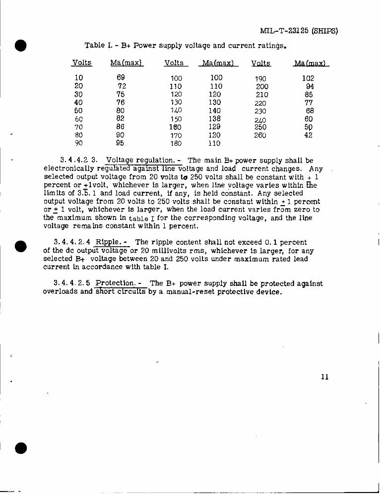
● Table I. - B+ Power suPply voltage and current ratings.
~ Ma (max) volts Ma(max) ~
10 69 100 10020
190 10272 110 110 200 94
30 75 120 120 21040 76 130 130 220 %50 60 140 140 230 6860 82 150 138 24070 86 160 129 250 $80 90 170 120 260 4290 95 180 110
3.4.4.2 3. Voltageregulation.- The main B+ power supplyshallbeelectronicallyre~ted againstlinevoltageand load current changes. Anyselected output voltage from 20 volts to 250 volts shall be constant with + 1percent or +lvolt, whichever is larger, when line voltage varies within fielimits of 3.%. 1 and load current, if any, is held constant. Any selectedoutput voltage from 20 volts to 250 volts shall be constant within ~ 1 percentor + I volt, whichever islarger,when theload currentvariesfrom zero tothe-maximum shown intable I forthecorrespondingvoltage,and thelinevoltageremains constantwithin1 percent.
.- The ripplecontentshallnotexceed O.1 percent● of ~3i~”S&&%~ge or zo mi~~ivo~ts rms, whichever is larger, for any
selected B+ voltage between 20 and 250 volts under maximum rated leadcurrent in accordance with table I.
3.4. 4.2.5 Protection. - The B+ power supply shall be protected againstoverloads and short circuits by a manual-reset protective device.
11
I ●
MIL-T-23125A(SHIFS)
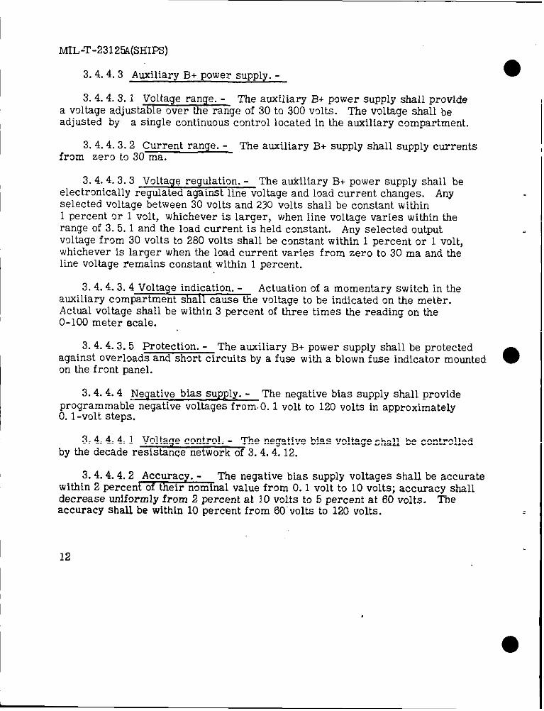
3. 4.4.3 Auxiliary B+ power supply.-
3.4.4.3.1 Voltagerange.- The auxiliaryB+ power supplyshzdlprovidea voltageadjustableover therange of30 to300 volts. The voltageshallbeadjustedby a singlecontinuouscontrollocatedin theauxiliarycompartment.
3. 4.4.3.2 Current range. - The auxiliary B+ supply shall supply currentsfrom zero to 30 ma.
3. 4.4.3.3 Voltage regulation. - The atiiliary B+ power supply shall beelectrically regulated against line voltage and load current changes. Anyselected voltage between 30 volts and 230 v~lts shall be constant within1 percent or 1 volt, whichever is larger, when line voltage varies within therange of 3.5. 1 and the load current is held cmstant. Any selectedoutputvoltage from 30 volts to 280 volts shall be constant withh 1 percent or 1 volt,whichever is larger when the load current varies from zero to30 ma and thelinevoltageremains constantwithin1 percent.
3. 4.4.3.4 Voltage indication. - Actuation of a momentary switch in theauxiliary compartment shall cause the voltage to be indicated on the meter.Actual voltage shall be within 3 percent of three times the reading on the0-100 meter ecale.
3. 4.4.3.5 Protection. - The auxiliary B+ power supply shall be protectedagainst overloads and short circuits by a fuss with a blown fuse indicator mountedon the front panel.
3.4. 4.4 Negative bias supply. - The negative bias supply shall provideprogrammable negative voltages from. O. 1 volt to 120 volts in approximatelyO. 1-volt steps.
3. 4.4.4.1 Voltage control. - The negative bias voltage shall be controlledby the decade resistance network of 3.4.4.12.
.- The negative bias supply voltages shall be accuratewithill~~&%%%%%%al value from 0.1 volt to 10 volts; accuracy shalldecrease uniformly from 2 percent at 10 volts to 5 percent at 60 volts. Theaccuracy shall be within 10 percent from 60’volts to 120 volts. =1
12 I

MIL-T-23125@IFS)
● 3.4.4. b Bias-off SUpplY.- A fixed negative voltage shall be providedof sufficiat volts ge to hold one eection of a dual section tube beyond cut~ffwhile the other eection is undergoing tests.
3.4.4.6 Positive bias supply. - A regulated fixed positive bias voltageof 7 1/2 volts + 1 percent shall be provided to allow the use of large self-biasresiskers in sf5?&al tube taste.
3.4.4.7 A. c. supplies .- An unregulated 250 volt a. c. supply and anunregulated 500 volt a. c. supply shall supply 200 ma for half-wave rectifiertests and 200 ma at 250 volts each side of the center tap for full-waverectifier tests. These supplies shall be protected by fuses installed in eachside of the power line to prevent damage from overloads or short circuits.
3.4.4.8 Signal SUPPIY.- The signal voltage shall be supplied from acalibrated and regulated source adjustable within O. 1 percent to 222 millivoltsat line power frequency. The signal voltage shall be constant witidn 1 percentwhen line voltage smd frequency vary within the range of 3.5.1.
3.4.4.9 Mutual conductance circuits. - The mutual conductance circuitsshall be capable of accurately measmring mutual conductance from 500 to128,000 micromhos in the presence of direct plate currents of less tkn 50 PS tomore than 100 ma.
3.4.4.9.1. Mutual conductance ranges. - The mutual conductance detec-tion bridge and the meter shunt and multiplier system shall be capable ofproviding the follpwing mutual conductance mid-scale values.
(a) 250 to 13,000 microtnlms mid scale in 50 micromho step.(b) 250 to 64,000 micranims mid scale in 250 micromh~ steps.
3.4.4.9.2 Accurac .---7---%
The equipment shall be capable of measuringmutual conductance o recel ng type electron tubes to witiln a basic toleranceof 3 percent. An inherent linear decrease in the mutual conductance reading asplate current increases shall be allowed. It shall be possible to maintain the3 percent tolerance on Gm by application of a correction factor to the meterreading in accordance with figure I.
13

MIL-T-23125A(SHIPS)
3.4. 4.9.3 Bridge balance. - The equipment shall provide for es@blish- ●ing bridge balance to elimimte d. c. current effects from Gm readings. Thebal.mwe controls and a swit,ch.to remove grid signal from the tube under testshall be located in the auxiliary compartment for use in special tests. Thebalance controls shall be marked to indicate the control settings for routinetesting.
3.4.4.9.4 Bridge protection. - A separate fuse with a blown fuse indicatorlocated on the front panel shall protect the bridge circuitry from excessivecurreate.
3.4.4, 10 Meter shunt and multiplier system. - A meter shunt systemskall be provided for making half-scale measurements in the ranqe of 50 uato 2.6 ma in 10 ya steps. Multipliers shall be provided for maki~g half-scalemeasurements from 50 us to 12.8 ma in 50 us steps and from 1 ma to 255 main 1 ma steps. All meter shunt and multiplier resistors shall be approvedtypee of 1 percent resistors.
3.4.4.11 Meter (voltage) multiplier system. - A meter multiplier systemshall be provided for making half-scale d. c. vol,tage measurements on 296 rangesin one-volt steps from 5 volts to 300 volts. The voltage measurements shall beaccurate within 2.5 percent of the mid-scale value.
3.4.4.12 Decade resistance network. - The decade resistance network shallprovide selected resistances from O ohm to 70, 000 ohms in 10 ohm steps.Each resistance value from 10 ohms to 10,000 ohms shall be within + 1 percent ●of the nominal selected value. Each resistance value between 10, 0~ ohms and70,000 ohms shall be with ~ 5 perc~t of thenominal selectedvalue. Allresistance values Up to 1000 ohms shall be capable of sustained operation at200 ma without damage. All resistance values from 1000 ohms to 70,000 ohmsshall be capable of sustained operation at 200 volts without damages.
3.4.4.13 Ca citors. - A non-polarized 4 pf capacitor with a d. c. voltagerating of a leas~ll be providedfmr by-passing resistance loadsduring tests of diode and rectifier tubes or special test circuit applications. Apolarized 800 @ ~0..volt capacitor shall be provided for by pasatng sd.f-resis -tance networka and special test circuit applications.
\
14
(
I

! MIL-T-23125A(SI-WFJ
● 3.4.5 Card programming system. - The system for eemi-automaticoperation of thls instrument shal 1 consist of a rugged card switch capableof performing all required operations without the use of relays or steppingswitches. The card switch shall be activated by the insertion of a pinchedcard, and deactivated by a manual operation which will release the cardfor retrmval from the switch.
3.4.5.1 Program capability. - The programming system shall be sodesigned as to allow flexible use of various circuit sections in performingmany types of tests. (This capability shall not be limited to &e tests specifiedherein but shall include types of tests which may be specified at a later date. )
3.4. 5.2 Fin selection. - A section of the card information storage andprogramming system shall be devoted to connecting the programmed testcircuit to the proper pins of the tube under test. Pin selection shall includepins 1 through 9, plus a cap for all tube test sockets specified in 3.6.6.5.
3.4.5.3 l%~gramming switch application. - The programming switchshall have the individual contact actuation levers arranued in the same manneras shown for the holes in the programming cards in F@re 2 with the individualswitches identified by the letter row and then the number row of the intsrceptpoint. The individual switch control of circuit values and intercomectionsshall be as follows:
● 3. 4.5.3.1 Tube test socket connections. - The tube sockets shsll beconnected as foll~ws:
Tube socket pin number Switches
1 ROWA switches 1 through 8.2 Row B switches 1 through 8.3 Row C switches 1 through 8.4 Rcw D switches 1 through 8.5 Row E switches 1 through 8.
15
I ●
MIL-T-23125A(SHIF@
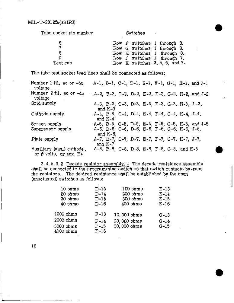
Tube socket pin number Switches
6 Row F switches 1 thrcmgh 8.7 Row G switches 1 through 8.8 Row H switches 1 through 8.9 Row J switches 1 through 7.
Test cap Row K switches 3, 4, 6, and 7.
The tube test socket feed linee shall be ccmnected as follows:
Number 1 fil, ac or +dcvoltage
Number 2 fil, ac or -dcvoltage
Grid supply
Cath~de supply
Screen supplySuppressor supply
Plate supply
Auxiliary (a~) cathode,~r fl volts, or aux B+
A-1, B-1, C-1, D-1, E-1, F-1, G-1, H-1, and J-1
A-2, B-2, C-2, D-2, E-2, F-2, G-2, H-2, ‘and J-2
A-3, B-3, C-3, D-3, E-3, F-3, G-3, H-3, J -3,and K-3
A-4, B-4, C-4, D-4, E-4, F-4, G-4, H-4, J-4,and K-4
A-5, B-5, C-5, D-5, E-5, F-5, G-5, H-5, and J-5A-6, B-6, C-6, D--6, E-6, F-6, G-6, H-6, J-6,
and K-6,A-7, B-7, C-7, D-7, E-7, F-7, G-7, H-7, J-7,
and K-7A-8, B-8, C-8, D-8, E-8, F-8, G-8, and H-8
3. 4.5.3.2 Decade resistor assembly. - The decade resistance assemblyshall be connected to the, pr~gramming switch so that switch contacts by-passthe resistors. The desired resistance shall be established by the open(unactuated) switches as follows:
10 ohms D-13 100 ohms E-1320 ohms D-14 200 ohms E-1430 ohms D-15 300 ohms E-1540 ohms D-16 400 ohms E-16
1000 ohms F-13 10j 000 ohms G-132000 ohms F-14 20,000 ohms G-143000 ohms F-15 30,000 ohms G-154000 ohms F-16

M_IL-T-23125A(SHI~)
● 3.4.5.3.3. Filament voltage.- The filament voltage shall k@establishedby actuating only the switches for the voltage required and the zero voltageswitch cm decades having a zero voltage rec@?ment.
Gne tenth volt decade
WILwge .Switch
0.0 A-II0.1 B-II0.2 C-II0.3 D-II0.4 E-II0.5 F-n0.6 G-II0.7 H-n0.8 J-110.9 K-1 1
One volt decade
Voltage Switch
o A-101 B-102 c-lo3 D-104 E-105 F-106 G .107 H-108 J-lo9 K-10
Ten volt decade
Voltage Switch
o A-910 B-920 c -930 D-940 E-950 F-960 G-970 H-980 J-990 K-9
100 L-9110 L-10
3.4. 5.3.4 Leakage current shunts. - During leakage tests theleakage current shall be selected singly or in combination to give a
●reject point current as follows:
Reject currentmicroam~eres
10205070
100150165
Switches actuated
NoneA-14B-14A-14; B-14C-14B-14; C-14A-14, B-l&, C-14
17
MIL-T-23125A(S~FS)
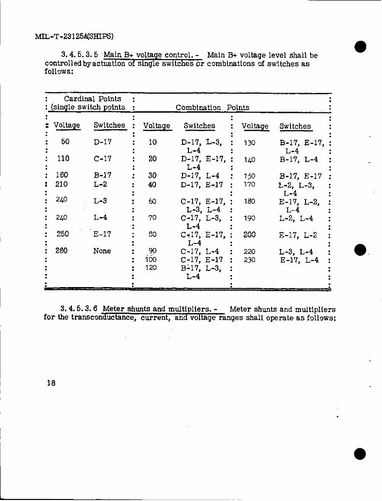
3.4.5.3.5 Main B+ voltage control. -controlled by actuation of single switches or combinations Qf switches as
Main B+ voltage level shall be●
follows: “
Cardinal Points : :: (single switch points : Combinaticm Points: : :: Voltage Switches : Voltage Switches : Voltage Switches :
: :: 50 D-17 : 10 D-17, L-3, : 130 B-17’, E-17, ;: L-4 L-4
C-17 ; 20 D-17> E-17, ; ILO:
: 110 B-17, L-4 :: L-4 :: 160 B-17 ; 30 D-17, L-4 : 150 B-1?, E-17 :: 210 L-2 : 40 D-17, E-17 : 170 L-2, L-3, :: .: 240
L-4L-3 : 60 C-17, E-17, i 160
:E-17, L-2, :
: : L-3, L-4 .: L-4: 240 L-4 70 C-17, L-3, : 190 L-2, L-4 :: : L-4: 250 E-17 : 80 C717, E-17, ;
:200 E-17, L-2 :
: : L-4 :: 260 None : .90 C-17, L-4 : 220 L-3, L-4 :
: 100 C-17, E-17 : 230 E-17, L-4 :: : 120 Bi17, L-3, : :: : L-4 : :
●
3.4.5.3.6 Meter shunts and multipliers. - Meter shunts and mtitipliersfor the transcon&ctance, current, and voltage ranges shall operate as follows:
18
●
m,-’r-23l 25A(SHIpS)
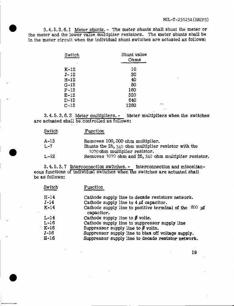
● 3.4.5 .3.6.1 Meter shunts. - The meter shunts shall shunt the meter orthe meter and the lower value multiplier resistors. The meter shunts shall bein the meter circuit when the individual shunt switches are actuated as follows:
Switch
‘o
K-12J-12H-12G-12F-12E-12D-12C-12
Shunt valueOhms
10204080
160320640
1280
3.4.5 .3.6.2 Meter multipliers. - Meter multipliers when the switchesare actuated shall be. controlled as follows:
Switch Function
A-13 Removes 100,000 ohm multiplier.L-7 Shunts the 25, 340 ohm multiplier resistor with the
1070 ohm multiplier resistor.L-12 Removes ‘1070ohm and 25,340 ohm multiplier resistor.
3.4.5.3.7 Interconnection switches, - Interconnection and miscellan-eous functions of individual switches when the switches are actuated shallbe as follows:
Switch
H-14J-14K-14
L-14L-16K-16J-16H-16
Function
Cathode supply line to decade resistors network.Cathode supply line to 4 @ capacitor.Cathode supply line to positive terminal of the 800 @
capacitor.Cathode suPply line to@ volts.Cathode supply line to suppressor supply lineSuppressor supply line to $ volts.Suppressor supply line to bias off voltage supply.Suppressor supply line to decade reststor network.
19
I●
MIL-T-23125A(SHIPS)
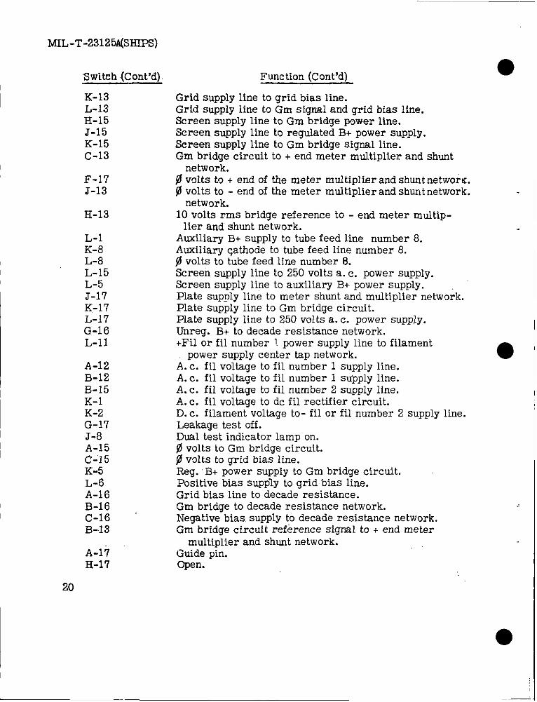
“Switch (Cent’d).
K-13L-13H-15J-15K-15C-13
F-17J-13
H-13
L-1K-8L-8L-15L-5J-17K-l 7L-17G-16L-II
A-12B-12B-15K-1K-2G-17J-8
I A-15C!-’i5K-5L-6A-16B-1 6(7-16B-13
A-I+H-17
20
Function(Cent’d)
Grid supplylinetogridbiasline.Grid supplylineto Gm signal and grid bias line,Screen supply line to Gm bridge power line.Screen supply line to regulated B+ power supply.Screen supply line to Gm bridge signal line.Gm bridge circuit to + end meter multiplier and shunt
network.~ volts to + end of the meter multiplier and shunt networ~.@volts to - end of the meter multiplier and shunt network.
network.10 volts rms bridge reference to - end meter multip-
lier and shunt network.Auxiliary B+ supply to tube feed line number 8.Auxiliary qathode to tube feed line number 8.fl volts to tube feed line number 8.Screen supply line to 250 volts a. c. power supply.Screen supply line to auxiliary B+ power supply.Plate supply line to meter shunt and multiplier network.Plate supply line to Gm bridge circuit.Plate supply line to 250 volts a. c. power supply.Unreg. B+ to decade resistance network.+Fil or fil number 1.power supply line to filament
power supply center tap network.A. c. fil voltage to fil number 1 supply line.A. c. fil voltage to fil number 1 supply line.A. c. fil voltage to fil number 2 supply line.A. c. fil voltage to dc fil rectifier circuit.D. c. filament voltage to- fil or fil number 2 supply line.Leakage test off.Dual test indicator lamp on.@volts to Gm bridge circuit.$ volts to grid bias line.Reg. B+ power supply to Gm bridge circuit.Positive bias supply to grid bias line.Grid bias line to decade resistance.Gm bridge to decade resistance network.Negative bias. supply to decade resistance network.Gm bridge circuit reference signal to + end meter
multiplier and shunt network.Guide pin.Open.
●
MIL-T-23125A(SHIPS)
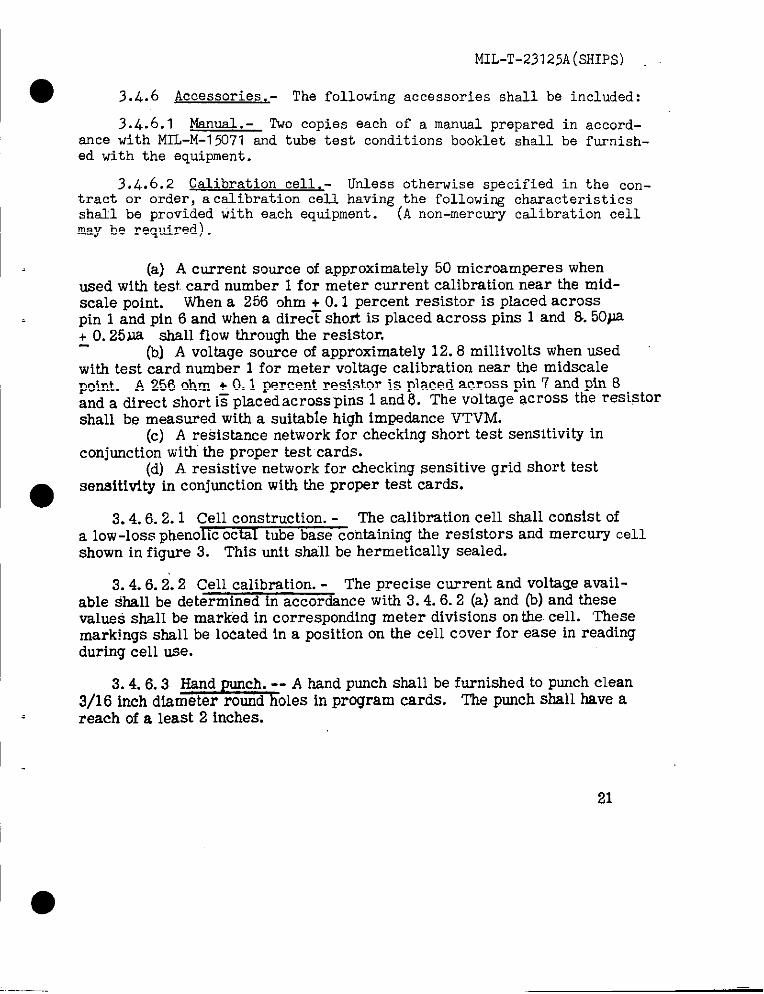
● 3.,L.6 Accessories. - The following accessories shall be included:
3.4.6.1 Manual .- Two copies each of a manual prepared in accord-ance with MIL-M-15071 and tube test conditions booklet shall be furnish-ed with the equipment.
3.4.6.2 Calibration cell .- Unless otherwise specified in the con-tract or order, a calibration cell having the following characteristicsshall be provided with each equipment. (A non-mercury calibration cellmay be required).
(a) A current source of approximately 50 microampere whenused with test. card number 1 for meter current calibration near the mid-scale point. When a 256 ohm + O.1 percent resistor is placed acrosspin 1 and pin 6 and when a direc~ shofi is placed across pins 1 and 8. 50PS~ O.25uzi shall flow through the resistor.
(b) A voltage source of approximately 12.8 millivolts when usedwith test card number 1 for meter voltage calibration near the midacalepoint. A 256 ohm + O. 1 percent resistor is. placed across pin 7 and pin 8and a direct short i= placed across pins 1 aud 8. The voltage across the resistorshall be measured with a suitable high impedance VTVM.
(c) A resistance network for checking short test sensitivity inconjunction with the proper test cards.
(d) A resistive network for checking sensitive grid short test
●sensitivity in conjunction with the proper test cards.
3.4.6.2.1 Cell construction. - The calibration cell shall consist ofa low-loss phenolic octal tube base containing the resistors and mercury cellshown in figure 3. This unit shall be hermetically sealed.
3. 4.6.2.2 Cell calibration. - The precise current and voltage avail-able shall be determined in accordance with 3. 4.6.2 (a) and (b) and thesevalues shall be marked in corresponding meter divisions on the. cell. ‘Thesemarkings shall be located in a position on the cell cover for ease in readingduring cell use.
3.4.6.3 Hand -- A hand punch shall be furnished to punch clean-3/1 6 inch dtameter round oles in program cards. The pumch shall have a
reach of a least 2 inches.
21
,
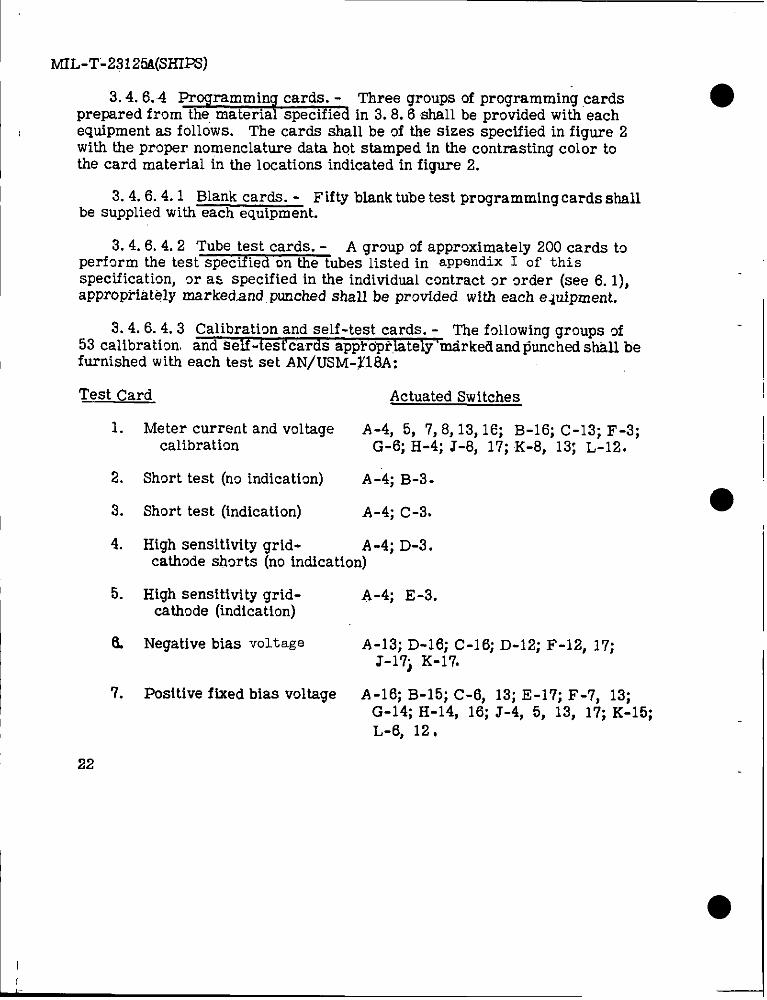
MIL-T-23125A(SHIPS)
3.4. 6.4 Programming cards. - Three groups of programming cards ●prepared from the material specified in 3.8.6 shall be provided with eachequipment as follows. The cards shall be of the sizes specified in figure 2with the proper nomenclature data hot stamped in the contrasting color tothe card material in the locations indicated in figtwe 2.
3. 4.6.4.1 Blank cards. - Fifty blank tube test programming cards shallbe supplied with each equipment.
3. 4.6.4.2 Tube test cards. - A group of approximately 200 cards toperform the test~ubes listed in appendix I of thisspecification, or as specified in the individual contract or mder (see 6. 1),appropriately markedxmd punched shall be prwided with each e~uipment.
3. 4.6.4.3 Calibration and self-test cards. - ne following groups of53 calibration and self -tesfcards appfdpriately “tirkefi and punched sh&ll tiefurnished with each test set AN/USM-~18A:
Test Card Actuated Switches
1.
2.
3.
4.
5.
8.
7.
22
Meter current and voltage A-4, 5, 7,8,13, 16; B-16; C-13; F-3;calibration G-6; H-4; J-8, 17; K-8, 13; L-12.
Short test (no indication) A-4; B-3.
Short test (indication) A-4; C-3.
High sensitivity grid- A-4; D-3.cathode shorts (no indication)
High sensitivity grid-cattmde (indication)
Negative bias voltage
Positive fixed bias voltage
A-4; E-3.
A-13; D-16; C-16; D-12; F-12, 17;J-17j K-17.
A-16; B-15; C-6, 13; E-17; F-7, 13;G-14; H-14, 16; J-4, 5, 13, 17; K-15;L-6, 12,
I
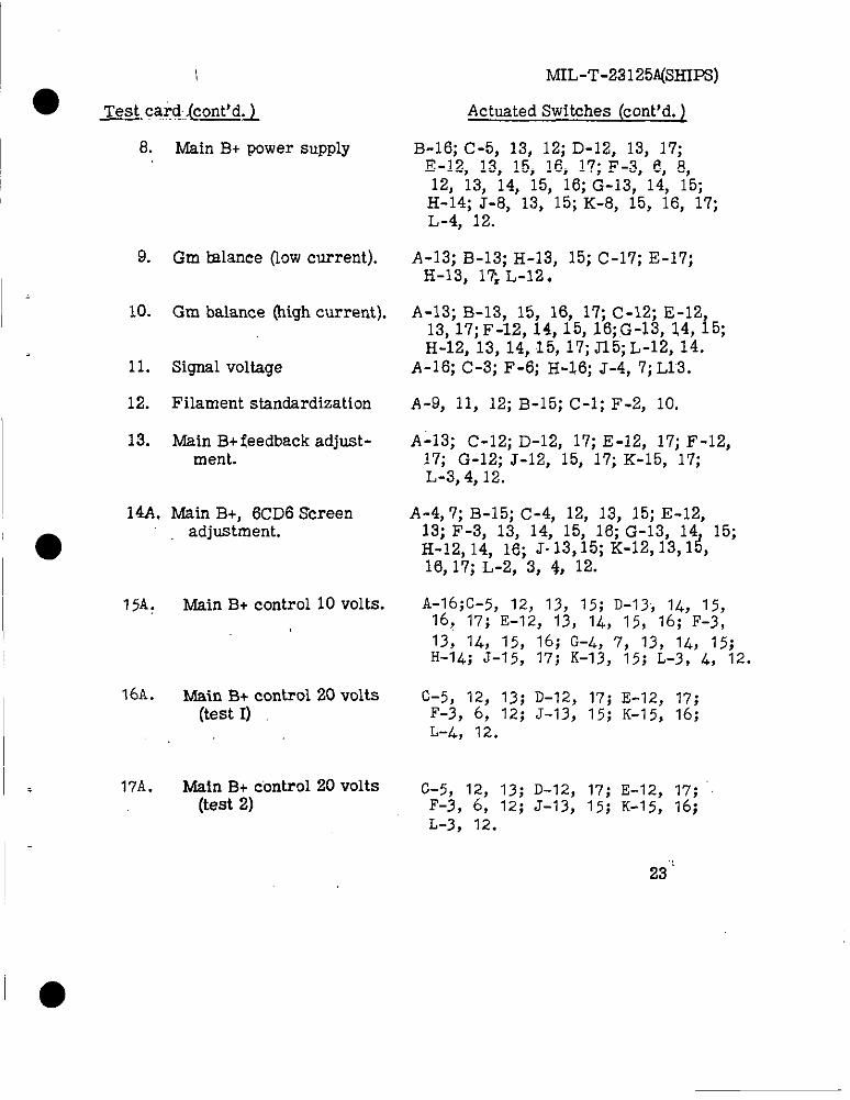
&Qca.rd,,(cont’d. )
8.
9.
10.
11.
12.
I 13.
Main B+ power supply
Gm tdance (low current).
Gm balance (high current).
Signal voltage
Filament standardization
Main B+ feedback adjust-ment.
1~. Win B+, 6cD6 Screenadjustment.
75A: Main B+ control10 volts.
16A. Main B+ control20 volts(test1)
17A. Main B+ control 20 volts(test 2)
MIL-T-23125A(SHIFS)
Actuated Switches (cent’d. ~
B-16; C-5, 13, 12; D-L?, 13, 17;E-12, 13, 15, 16, 17; F-3, ~, 8,12, 13, 14, 15, 16; G-13, 14, 15;
H-14; J-8, 13, 15; K-8, 15, 16, 17;L-4, 12.
A-13; B-13; H-13, 15; C-17; E-17;H-13, 13 L-12.
A-13; B-13, 15, 16, 17; C-12; E-1213, 17; F-12, 14, 15, 16; ,G-13, 14, i5;H-12, 13, 14, 15, 17; J15; L-12, 14.
A-16; C-3; F-6; H-16; J-4, 7; L13.
A-9, 11, 12; B-15; C-1; F-2, 10.
A-13; C-12; D-12, 17; E-12, 17; F-12,17; G-12; J-12, 15, 17; K-15, 17;L-3, 4, 12.
A-4, 7; B-15; C-4, 12, 13, 15; E-12,13; F-3, 13, 14, 15, 16; G-13, 14 15;H-12, 14, 16; J-13,15; K-12,13,1&16, 17; L-2, 3, ~, 12.
A-16;c-5, 12, 13, 15; D-13j 14, 15,16? 17; E-12, 13, 14, 15, 16; F-3,13, 14, 15, 16; G-4, 7, 13, 14, 15;H-14; J-15, 17; K-13, 15; L-3, 4, 12.
C-5, 12, 13; D-12, 17; E-12, 17;F-3, 6, 12j J-13, 15; K-15, 16;L-4, 12.
C-5, 12, 13; D-12, 17; E-12, 17;F-3, 6, 12; J-13, 15; K-15, 16;L-3, 12.
23”
MIL-T-23125A(SHII%)
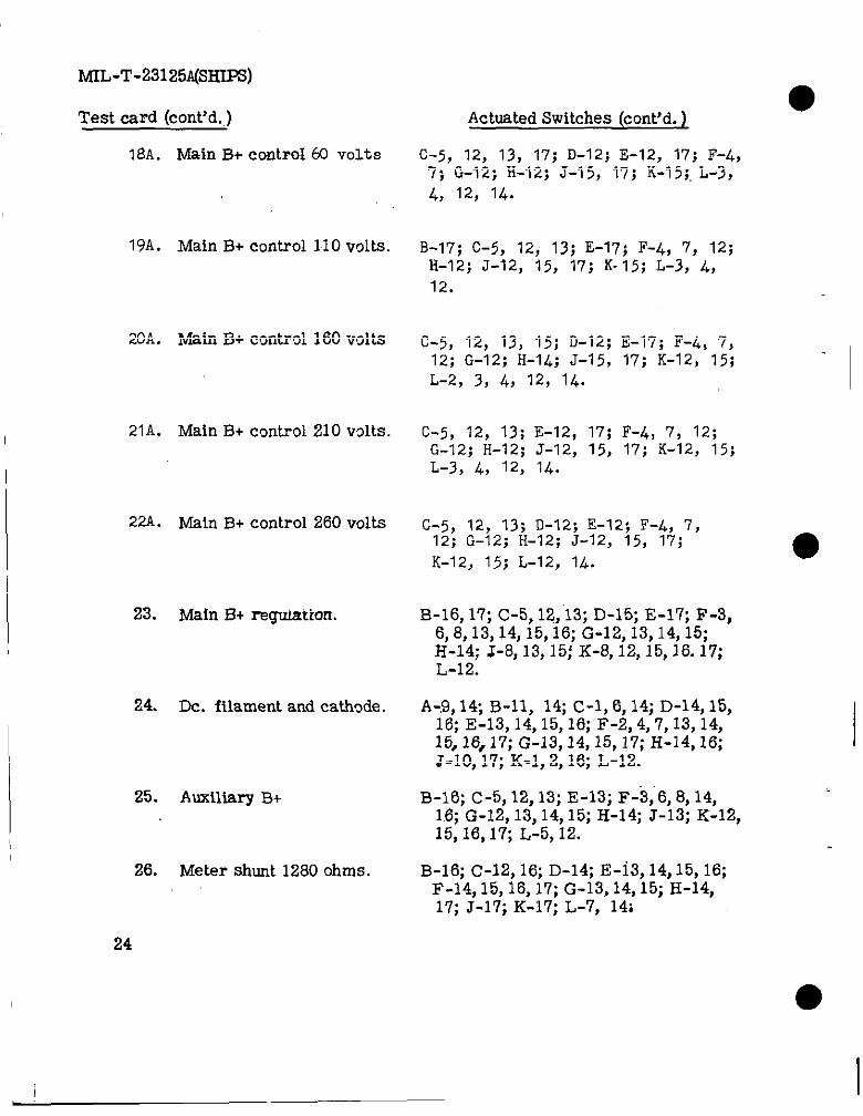
Test card (cent’d. )
18A. Main B+ CO?ltFOI60 volts
19A. Main B+ control110 volts.
20A. Main B+ ccmtrd 160 volts
21A. Main B+ control210 volts.I
22A. Main B+ control260 volts
23. Main B+ reg-umtton.
24. Dc. filament and cathode.
25. Auxiliary B+
26. Meter shunt 1280 ohms.
●Actuated Switches (cent’d. )
C-5, 12, 13, 17; D-12; E-12, 17; F-4,7; G-12; II-12; J-15, 17; K-15;. L-3,1$, 12, 14.
B-17; C-5, 12; 13; E-17; F-4, 7, 12;H-12; J-12, 15, 17; K-15; L-3, 4,
12.
C-5, 12, 13, 15; D-12; E-17; F-4, 7,12; G-12; H-14; J-15, 17; K-12, 15;L-2, 3, 4, 12, 14.
C-5, 12, 13; E-12, 17; F-4, 7, 12;G-12; H-12; J-12, 15, 17; K-12, 15;L-3, 4, 12, 14.
c-5, 12, 13; D-12; E-12; F-4, 7,12; G-12; H-12; J-12, 15, 17;K-12, 15; L-12, IL.
B-16, 17; C-5, 12, 13; D-15; E-17; F-3,6,8,13,14, 15,16; G-12, 13,14, 15;H-14; J-8, 13, 15; K-8, 12,15,16. 17;L-12.
A-,9, 14, B-11> 14; C-1, 6, 14; D-14, 15,16; E-13, 14,15, 16; F-2,4, 7,13,14,15, 16,17; G-13, 14,15, 17; H-14, 16;J-10, 17; K-1, 2, 16; L-12.
B-16; C-5, 12, 13; E-13; F-3;6, 8,14,16; G-12, 13,14, 15; H-14; J-13; K-12,15, 16,1fi L-5, 12.
B-16; C-12, 16; D-14; E-i3, 14,15, 16;F-14, 15,16, 17; G-13, 14, 15; H-14,17; J-17; K-17; L-7, 14;
I
24
I
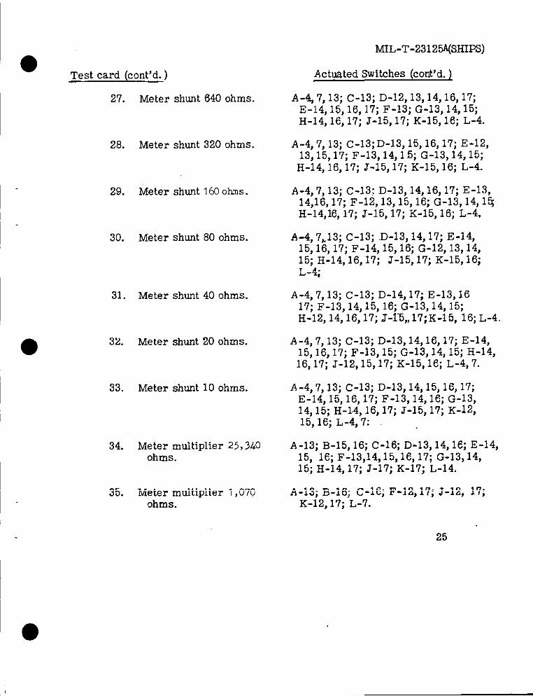
● “Test card (cent’d. )
27. Meter shont 640 ohms.
28. Meter shunt 320 ohms.
29. Meter shunt 163 ohms.
30. Meter shunt 80 ohms.
31. Meter shut 40 ohms.
32. Meter shunt 20 ohms.
33. Meter shunt 10 ohms.
34. Meter multiplierohms.
35. Meter multiplierohms.
25,340
1,070
MIL-T-2312@(SHIPS)
Actusted Switches (cent’d. )
A-4 7, 13; C-13; D-12, 13,14,16, 17;E-14,15, 16, 17; F-13; G-13, 14, 15;H-14, 16, 17; J-15, 17; K-15, 16; L-4.
A-4,7, 13; C-13; D-13, 15,16, 17; E-12,13, 15,17; F-13, 14,1.5; G-13,14, 15;
H-14, 16, 17; J-15, 17; K-15, 16; L-4.
A-4,7, 13; c-13; D-13, 14,16, 17; E-13,14,16, 17; F-12,13, 15, 16; G-13, 14, 1~H-14,16, 17; J-15, 17; K-15, 16; L-4,
A-4, 7>13; C-13; D-13, 14, 17; E-14,15,16, 17; F-14, 15, 16; G-12, 13,14,15; H-14,16, 17; J-15, 17; K-15,16;L-4;
A-4, 7,13; C-13; D-14,17; E-13,1617; F-13, 14,15, 16; G-13, 14, 15;H-12, 14,16, 17; J-1-5,, 17; K-15, 16; L-4.
A-4, 7, 13; C-13; D-13,14,16, 17; E-14,15,16, 17; F-13,15; G-13, 14, 15; H-14,16, 17; J-12,15,17; K-15,16; L-4, 7.
A-4,7, 13; C-13; D-13, 14,15, 16, 17;E-14, 15, 16, 17; F-13, 14,16; G-13,14, 15; H-1.4, 16, 17; J-15, 17; K-12,15,16; L-4,7; ,
A-13; B-15, 16; c-16; D-13, 14, 16; E-14,15, 16; F-13,14,15,16, 17; G-13,14,15; H-14, 17; J-17; K-17; L-14.
A-13; B-16; C-16; F-12,17; J-12, 17;K-12, 17; L-7.
25
MIL-T-231,25A(SHIPS)
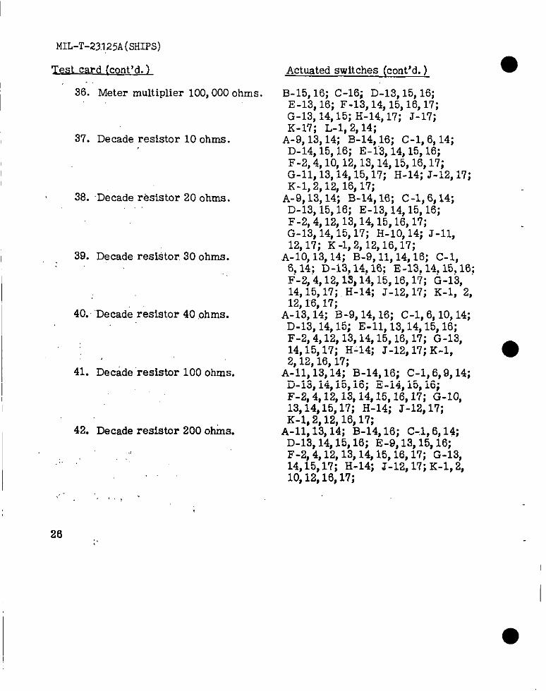
Test card (cent’d. ),..
I36. Meter multiplier 100,000 ohms.
37. Decade resistor 10 ohms.
38. Decade resistor 20 ohms.
I 39. Decade restitor. 30 ohms.:.
~40. ”‘Decade resistor 40 ,ohms.
41. Decade ‘resistor 100 ohms.
42. Decade resistor 200 oh&s.I
.,’
%“,’,,,;.
Actuated switches (cent’d. )
B-15, 16; C-16; D-13, 15, 16;E-13, 16; F-13, 14, 15,16, 17;G-13, 14, 15; H-14, 1’7; J-17;K-17; L-1. ”2.14:
A-9, 13, 14; ‘B~14; 16; C-1,6, 14;D-14, 15, 16; E-1-3, 14, 15, 16;F-2, 4,10, 12, 13,14,15,16, 17;G-II, 13,14,15, 17; H-14; J-12, 17;K-1, 2,12,16, 17;
A-9, 13, 14; B-14, 16; C-1, 6, 14;D-13, 15, 16; E-13, 14,15, 16;F-2, 4,12, 13,14,15,16, 17;G-13, 14,15, 17; H-10, 14; J-ll$12,17; K-1,2, 12,16,17;
A-10, 13, 14; B-9, 11, 14, 16; C-1,6, 14; D-13, 14, 16; E-13, 14,15, 16;F-2, 4,12, 13,14,15,16, 17; G-13,14,15, 17; H-14; J-12, 17; K-1, 2,12,16. 17;
A-i3, i4; B-9, 14, 16; C-1,6, 10, 14;D-13, 14, 15; E-n, 13,14,15, 16;F-2, 4,12, 13,14,15,16, 17; G-13,14,15, 17; H-14; J-12, 17; K-l,2,12,16, 17;
A-n, 13, 14; B-14, 16; C-1, 6,9, 14;D-13, 14,15, 16; E-14, 15, 16;F-2, 4,12,13,14,15,16, 17; G-10,13,14,15, 17; H-14; J-12, 17;K-1, 2,12,16, 17;
A-n, 13, 14; B-14, 16; C-l, 6, 14;D-13, 14,15, 16; E-9, 13,15, 16;F-2, 4,12,13,14,15,16, 17; G-13,14,15,1’7; H-14; J-12, 17; K-1,2,10,12,16, 17;
26 :,
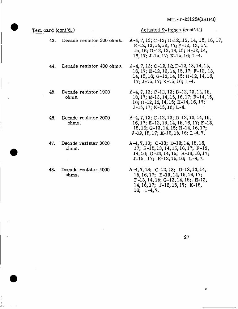
● Teat card (cent’d. )
43. Decade resistor 300 ohms.
44. Decade resistor 400 ~hms.
●
45. Decade resistor 1000ohms.
46. Decade resistor 2000ohms.
47. Decade resister 3000ohms.
48. Decade resistor 4000ohms.
MfL-T-23125@HIPS)
Actuated Switche~~c4.!t~d.
A-4, 7, 13; c-13; D-12,.13; 14, 15, 16, 17;E-12, 13,14,16, 17; F-12, 13, 14,15, 16; G-12, 13,14, 15; H-12,14,16, 17; J-15, 17; K-15, 16; L-4.
A-4,7,13; c-12,1 ~D-12,13,14,15,16, 17; E-12, 13,14,15, 17; F-12, 13,14,15,16; G-13,14,15; H-12,14,16,17; J-15, 17; K-15, 16; L-4.
A-4, 7, 13; c-12,13; D-12, 13,14,15,16,17; E-13,14,15,16,17; F-14,15, I16; G-12,13 14,15; H-14,16, 17;J-15, 17; K-15, 16; L-4.
A-4,7, 13; c-12,13; D-12, 13,14,15,16,17; E-12, 13,14,15,16, 17; F-13,15,16; G-13,14,15; H-14, 16, 17;
J-12, 15, 17; K-12, 15, 16; L-4, 7.
A-4, 7, 13; c-13; D-1~14, 15,16,17; E-12,13,14,15,16,17; F-13,14, 16; G-13,14, 15; H-14, 16,17;J-15, 17; K-12, 15, 16; L-4, 7.
A-4,7, 13; c-12, 13; D-12,13, 14,15,16,17; E-13,14,15,16,17;F-13,14, 15; G-13,14, 15; .H-12,14,16,17; J-12, 15,17; K-15,16; L-4, 7.
27
.
MIL-T-23125A(SHIPS)
I r.—, –- –.., ,. ...,., ,
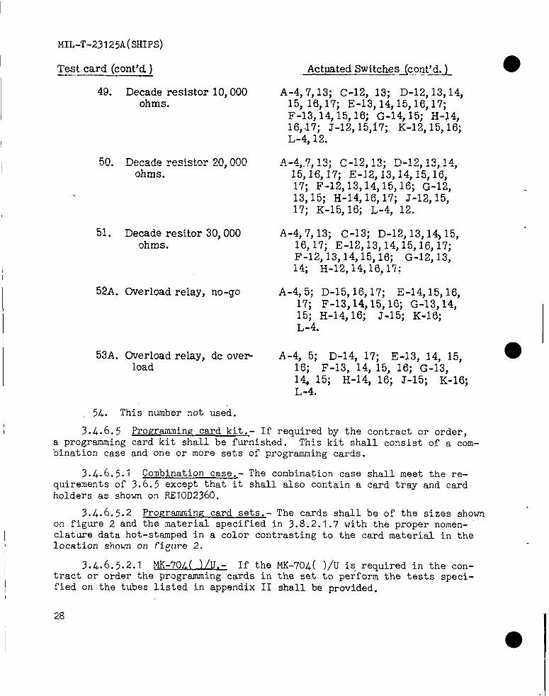
49. Decade resistor 10,000ohms.
50. Decade resistor 20,000ohms.
51. Decade resitor 30,000ohms.
I 52A. Overload relay, no-go
I53A. Overload relay, dc over
load
Actuated SwitchesJc,ont’d.~.—— ___ .._—.
A-4, 7,13; c-12, 13; D-12, 13,14,15, 16,17; E-13,14,15,16,17;F-137 ”14,15, 16; G-14, 15; H-14,16,.17; J-12, 15,17; K-12, 15, 16;L-4, 12.
A-4,.7, 13; c-12,13; D-12, 13,.14,15,16,17; E-12,13,14,15,16,17; F-12,13,14,15,16; G-12,13,15; H-14, 16,17; J-12, 15,17; K-15, 16; L-4, 12. “
A-4, 7, 13; c-13; D-12,13,1% 15,16,17; E-12,13,14,15,16,17;F-12,13,14,15,16; G-12,13,l% H-12,14,16,17;
A-4,5; D-15,16,17; E-14,15,16,17; F-13, 14,15, 16; G-13, 14,15; H-14, 16; J-15; K-16;L-4.
A-4, 5; D-14, 17; E-13, 14, 15,16; F-13, 14, 15, 16; G-13,l% 15; H-14, 16; J-15;L-4.
K-16;
order,
I 54. This number not used.I
3.4.6.5 prom-amine card kit. - If required by the contract ora programming card kit shall be furnished. This kit shall consist of a c&m-bination case and one or more sets of programming cards.
3.4.6.5.1 Combination case.- The combination case shall meet the re-quirements of 3.6.5 except that it shall also contain a card tray and cardholders as shown on KEIOD2360.
3.4.6.5.2 ProErsmming card sets.- The cards shall be of the sizes shownon figure 2 and the material specified in 3.8.2.1.7 with the proper nomen-
1 clature data hot-stamped in a color contrasting to the card material in theI location shown on figure 2.
3.4.6.5.2.I MK-70A( )/U.- If thetract or order the programming cards infied on the tubes listed in appendix II
MK-70L( )/U is reauired in the con-the set to pe<for~shall be provided.
the tests s,peci-
28
● 3.4.6 .5.2.2 MK- ( )/ u.-the programming cards in the settubes listed in appendti III.
MIL-T-23125A(SHIPS)
If the MK- ( )/U is required (see 6.I)shall perform the tests specified on “the
3.4.6.5.3 l.K- ( )/U. - If MC- ( )/U is required (see 6. I ) a setof programming cards shsll be provided to perform the tests specified onthe tubes listed in appendix IV.
3.5 Electrical requirements.-
3.5.1 Power source .- The test set shall operate from 115 volts ~ 10percent single phase input at m cps ~ 5 perCent, @ cps t 5 Perc@nt, Or 400cps, ~ 10 percent.
3.5.1.1 V~tap e trsn sients _- The equipment shell be capable of with-standing a “voltage transient of ~ 20 percent from any point within the ~ 10percent. steady-state tolerance band of 3.5.1, recoverable to this point with-in two seconds. Momentary impairment of operation during the transient ispermiasibl~ but the transient ahsll not prevent resumption of normal operation.
3.5.1,2 Frequency transients. - The equipment shall be capable ofoperation during frequency transients of ~ 3 percent, of which not morethan one percent is outside the steady-state tolerance band of frequencyas specified in 3.5.1. The transient shall recover to the steady-statefrequency within this band within 2 seconds. Momentary impairment ofoperation during the transient is permissible, but the transient shall
● not prevent resumption of normal operation.
3.5.2 Total power.- The maximum power required to operate the testset SW not axceed 250 watts. The power required to operate the testset with no card inserted in the card switch shall not exceed 80 wattswhen the equipment is operating from a 115 volt 63 CPS source. When theequipment is operating from a ED CPS or 400 cps source the power consumedshall be not more than 10 percent greater than the power consumed at @ cpsinput with other conditions remaining constant.
3.5.3 Overload protection.- A fuse shell be installed in each sideof the power line between the power source and the power switch circuit.
3.5.4 Radio interferencerequirements.- The equipment shall fneetthe applicable radio interferencerequirements of MIL-I-16910 for portableequipment. Ahy parts employed for the reduction of radio interferencesuch as capacitors and filters shall be approved by the Bureau of Ships.
3.5.4.1 Test socket wiring.- Test sockets shall be wired with appro-priate suppression devices for eltiination of parasitic oscillations duringtube tests.
29
MIL-T-23125A(SHIFE)
●
I 3.6 Mechanical requirements. -
3. 6.1 Size. - The over-all dimensions of the equipment, including thecover, handle, latches and feet shall not exceed 19- 1/2 inches wide by 10-incheshiqh by 17-1/4 inches deep. Dimensions excludina handle or hsmdles. latchesand feet shall not exceed i9-1/2 inches wide by 9-i/2 inches high by ~6-1/2
~inches deep.
I 3.6; 2 Weight. - The over-all weight of the equipment,. including the coverand accessories except the tube test cards, shall be held to a minimum consistentwith requirements specified herein and shall not exceed 50 pounds.
3.6.3 Finish. - The exterior finish of the instrument shall be gray enamelin accordan~ype III, class 2, of MIL-E-15090.
I
3“6”4-%% The construction shall allow maximum accessibilityto internal parts an su assemblies.
3.6.5 Combination case. - The equipment shall be enclosed in a combinationcase constructed in accordance with the requirements of MIL-T-945. Thecase shall be dripproof in accordance with ML -STD- 108. The cover shall beapproximately two inches in depth. The case shall be provided with two setsof four dimples, one set on the bottom and one set on the rear. Two trunk-type pull-down latches (hooks in the cover, latches in tAe case) and two separ-able hinges (hooks with cover cross -bar in the csse), shall be provided. Aone hinge metal handle mounted on the side between tbe latches, shall beprovided. No conductive projections or contacts on the outside of the caseshall be connected to the equipment ground.
3.6.5.1 Identification Plate. - The identification plate shall be =lxed tothe outside top of the combination case.
3.6. 5.2 Accessory stowage. - The technical manual, the calibration cell,the hand punch, tAe test program cards, and the blsnk program cards shallbe stowed in the cover of the combination case. The tube test program cardsshall be stowed in the case. Five sp=e fuses shall be stowed in an appropriate
1 container under the perforated power supply cwer.I
I 30
Ii

MIL-T-23125@HIl%)
3.6.6 Panel. - The layout of the panel shall be approved by the Bureau ofShips.
3. 6.6.1 Panel marking. - Panel markings shall be engraved, cast, oretched into the panel. Silk screen processes shall not be used. The psmelmarkings shall be filled yiti a permsnent white material.
3.6.6.2 Fluorescent fillinq. - When required (see 6. 1) fluorescentfilling shall be used in the P@l markhg, knob pointers, meter scales, andmeter pointer to facilitate operation in subdued light.
3. 6.6.3 Controls. - All controls necessary for normal operation of theequipment shaH be placed on the front panel. Controls for additional ‘tests tobe performed by skilled personnel shall be in an auxilisr y compartmentaccessible through a hinged cover plate in the front panel. If internal-externalconcentric controls are used, the internal knobs shall be of such design thatit will be possible for the operator to turn them wiiile wearihg gloves withoutturning the external knobs.
3.6. 6.3.1 Main panel. - Gnly”the following controls shall be required fornormal equipment operation by unskilled personnel.
3. 6.6.3.1.1 Power switch. -● In the off position,
The power switch shall be a toggle switch.it shall disconnect both sides of the power line from the
equipment by de-energizing the line slave relay. In the on position, it shallrestore power to tie instrument by momentarily energ{~ing the line slave relaycircuit.
3. 6.6.3.1.2 Test button number 2.- A test button besring the numeralshall actuate the quality or Gm test switch.
3. 6.6.3.1.3 Test button. number 3.- A test button bearing the numeral 3shall actuate the gas test switch.
3. &6.3. 1.4 Test button number 4.- A test button besring the numeral 4shall actuate a switch connecting the elements of the second section of a dual-section tube for testing when the tests of the first section have been completed.
31
MIL-T-23125A(SHIPS)
3.6.6 .3.1.5 Card release knob .- The card release knob shall open allcard switch contacts and release the program card.
3.6.6 .3.1.6 Power cable assemble. - The power cable assembly shall betype B in accordance with Drawing RE62D2005.
3.6..6.3.2Auxiliary compartment. - The following controls and adjustmentsshall be available in the auxilbry compartment for special tests and routinecalibrations to be performed by skilled personnel.
3.6.6 .3.2.1 Filament standardization pushbutton switch. - A pushbuttonswitch shall be provided to cause the relative filament mltage level to be indi -cated on the meter.
3. 6.6.3.2.2 Filament standardization adjustment. - A multi-position rotwyswitch shall control the filament voltage standardization.
3.6.6 .3.2.3 Sensitive grids shorts, pushbutton switch. - A pushbutton switchshall be available f=kasing h e sensitivity of the grid-to-cathode short test.
3. 6.6.3.2.4 Cathode activity test pushbutton switch. - A locking pushbuttonswitch shall be provided to, reduce filament voltage for a qualitative test Ofcathode activity.. This switch shall dkengage when any of the other auxiliary epushbutton switches sre actuated.
3. 6.6.3..2.5 Auxiliary B+ pushbutton switch. - A pushbutton switch shallbe provided to cause ti e obtput voltage of the auxiliary B+ power supply to beindicated on the meter.
3.6.6.3.2.6 AuxiliaryB+ adjustment.- A continuouslyvariablecontrolshallcontrolthe outputvoltageoftieauxiliaryB+ power supply.
32
III

MIL-T-23125!(sHII%)
3.6.6.3.2.’7 Grid signal pushbutton switch. - A locking pushbutton switchshall be provided to disconnect the grid signal from the tube under test whenGm bridge balsnce adjustments are made. This switch shall disengage whenany of the other pushbutton switches in the auxiliary compartment are actuated.
3. 6.6.3.2.8 Gm bridge balance adjustments. - Two continuously variablecontrols shall he provide~one for low current balance,tie other for high current balance.
‘3.6. 6.3.2.9 Short test calibration adjustments. - Two screwdriver-adjusted potentiom~st calibration, one forthe normal sensitivity range and one for the high sensitivity grid shorts range.
3.6.6.3.2.10 Bias voltage calibration adjustments. - Two screwdriver ad-iusted uotentiometers shall be cmovided for bias calibration. one for ~ositivekiss a“d one for the programmable negative bias. The nega~ive bias &alibrationadjustment shall be provided with a locking nut on the shaft.
3.6.6.3.2.11 Main B+calibration adjustment. - A screwdriver-adjustedpotentiometer shall be provided for calibration of the main B+ power supplyvoltage. The adjustment shall be ‘provided with a locking nut on the shaft,
● 3.6.6.3.2.12 Signal voltage calibration. - Two screwdriver-adjusted potentio-meters shall be urovided for calibration of the sicmal volt~e, one to adjust tieregulation of the’ signal voltage with line variatio& and on: to set the Signalvoltage amplitude. These adjustments shall be provided with a locking nuton the shafts.
3.6.6.3.2.13 Meter calibration. - A screwdriver-adjusted potentiometershall be provided for calibration of the millivolt range of the meter. Theadjustment shall be provided with a locking nut on the shaft.
3.6.6.3.2.14 Fltament standardization calibration. - A screwdriver-adi usted Potentiometer shall be urovided to adi ust the meter for Droper indication
I...
of tie st~dard filament voltage:. .
3.6.6.4 Indicators. - All indicator lamps and the meter shall be on tie frontpanel.
33
.
I
MIL-T-2312USHIPS)
3.6. 6.4.1 Pitdt light. - A pilot light shall ind~cate when the equipment is ●turned on.
3. 6.6,4.2 Blown fuse indicators. - Three blown fuse indicators shall beprovided, one for the Gm bridge fuse, one for the auxiliary B+ power SUDDIYfuse, and one for the d. c. filament supply fuse. Each ind~cator” shall be-rn&ntedadj scent to its associated fuse and shall light if its fuse fails..
3. 6.6.4.3 Grid signal off indicator. - A grid signal off lamp shall lightwhen the grid signal disconnect pushbutton switch in tie auxiliary compartmentis actuated.
3. 6.6.4.4 Cathode activity test indicator.- A cathode activity test indicatorlamp shall light when the cathode activity test pushbutton switch is actuatedlowering filament voltage.
3.6.6.45 Dual test indicator. - A neon lamp shall light when a dual-sectiontube is undergo~ at test button number 4 be used to test thesecond section.
3.6.6.4.6 Short test indicators. - The five neon short test lamps shall bemounted in line on the frent ~“ne=r a glare shield.
3.6. 6.5 Tube sockets. - Eleven tube sockets shall be supplied with theequipment . A jumbo 9-pin socket, an in-line subminiature socket and a round ●subminiature socket shall be installed on the front panel. A replaceable tubesocket plate shall carry a grid cap lead with a clip and the following tube sockets:
(a) 7-pin miniature (e) 7 pin(b) 9-pin miniature (f) 6 pin(c) Octal (g) 5 pin(d) Loctal (h) 4 pin
3.6.6.6 ‘Tube pin straighteners. - Pin straighteners for, 7-pin and 9-pinminiature tubes shall be mounted on the frc~ panek The straighteners shallhave sleeves above the straightening section to insure proper alignment of thepins with the tube shell.,.
I
● 3.6.6.7auxiliary B+
MIL-T-23125A(SHIPS)
Fuse recerhacles.- Receptacles for fuses for the Cm bridge,supply, d.c. filament supply and each side of the poiferline
shall be-mounted-on”the front panel. -
3.6.6.8 Instmction Dlate.- Aninstructions shall be fastened to the
3.6.6.9 Card switch.- The cardin the lower left-hand section of the
aluminum plate bearing brief operatinginside cover.
switch mechanism shali be installedDanel in a msnner to provide easy
insertion and removal of the test card;.
3.7 Environmental requirements. -
3.7.1 shock. vibration. and inclination .- ‘fhis equipment shall meetthe shock, vibration, and inclination requirements of MIL-E-16LO0.
3.7.1.1 ‘fhe test set shall withstand the grade A, Claas 1, type Ashock test for lightweight equipment in accordance with MIL-S-901.
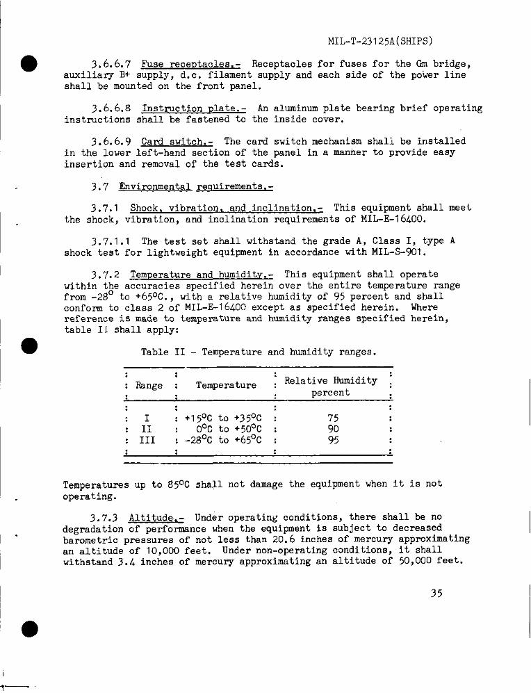
3.7.2 ‘femuerature and humiditv. - This equipment shall operatewithin the accuracies specified herein over the entira temperature rangefrom -28° to +65°C.. with a relative humiditv of 95 uercent and shallconform to class 2 of MIL-E-16400 except as specified herein.reference is made to temperature and humidity ranges specifiedtable I i shall apply:
Table II - Temperature and humidity ranges.
: Rsnge : Temperature : Relative Humidity ~percent
I : +15’3Cto +350C : 7511 Ooc to +500C : 90
: III ; -28°C to +65°C : 95
Temperatures up to 85°C shall not damage the equipment when itoperating.
Whereherein,
is not
3.7.3 Altitude.- Under operating conditions, there shall be nodegradation of perfomnance when the equipment is subject to dacreasedbarometric pressures of not less than 20.6 inches of mercury approximatingan altitude of 10,000 feet. Under non-operating ccmditiona, it shallwithstand 3.4 inches of mercury approximating an altitude of 50,000 feet.
35
MIL-T-23125A(SHIPS)
3.8 ~arts and materials requirements.- Regardless of any other ●requirements,materials, and parts containingmercury shall not be usedin this equipment unless specifically required or approved and unless thepresence of mercury is noted in that requirement or approval.
3.8.1 Materials.- The materials used in this equipment shall beselected in accordance with the requirements of MIL-E-16400.
3.8.1.1 Corrosion.- The equipment shall be protected from corrosionin accordance with MIL-E-164oo.
3.8.1.2 Flmzus.- The materials used in this equipment shill beselected in accordance with the fungus inert materials required ofMIL-E-I 6400. The gene ral fungus resistant treatment and the requirementfor coating soldered joints and wire with varnish as specified inMIL-T-945 shall not apply,
3.8.2 parts .- Unless otherwise specified herein, all parts usedin this equipment shall be selected in accordance with the requirementsOf MIL-E-1 6400.
3.8.2.1 Standard Darts, - Unless otherwise specified herein orotherwise approved by the Bureau of Ships, all parts shell be standardparts as defined in MIL-E-164oo.
3.$.2.1.1 Electron tubes and semiconductor devices. - Electron tubesand semi-conductor devices used in this equipment ehall be selected ●in accordance with the following documents:
(a) Electron tubes - MIL-STD-200 and Navy(b) Semiconductors (includingtransistors
diodes) - MIL-STD-701.
Supplement thereto.and semiconductor
3.g.2.1.2 Transformers and inductors.- All audio, power and pulsetransformers and inductors shall conform to grade 4 or 5, class R, S,OrT, life expectancy X, in accordance with MIL-T-27 and class 2 ofMIL-E-16400 except that low level pulse transformers shall conform toMIL-T-21038.
3.8.2.1.2.1 ‘frsnsformer dia<rsms.- A transformerdiagram shallbe printed on the case of each transformer,or on a plate attached tothe case. The diagram shall also be available in the technical manual.All other data pertinent to the transformer type shall be marked on thetransfonsercase ae required in MIL-T-27.
3.g.2.1.3 Capacitors.- All polarized filter capacitors shall be”octal plug-in types, and shall be clamped to avoid objectioneble vibrationwith the exception of the filter capacitor in the meter protectioncircuit and the differential capscitor in the GM bridge.
36

kilL-T-231 25A(.5HIps)
● 3.8.2.1.4 Indicatimz meter .- Except as speciried herein, theindicating meter shall meet the requirements of MIL-M-10304.
3.8.2 .1.4.1 Meter sensitivity .- The meter shall have a 10O-micro-ampere full-seals sensitivity. The meter shall be of a torsion (taut-band) construction. Friction ( jewel) bearings shall not be used.
3.8.2.1.4.2. Accuracy .- The accuracy of the meter shall be ~ 2 per-cent of full scale, except for the mid-seals point which shall beaccurate to ~1/2 percent of the full scale value.
3.8.2 .1.4.3 & The meter case shall be 4-1/2 inches in diameter.
3.8.2 .1.4.4 overload .- ‘fhe meter by itself shall be capable ofwithstanding a momentary overload of twenty-five times its full-scalecurrent value either up or down scale without sustaining mechanical orelectrical damage. Sudden positive or negative overloads of 163o ua. ,or more, from zero meter reading shall activate the solid-state meterprotection device which, in turn, will cause the slave relay tode-energize and to disconnect both sides of tk power line.
3.8.2 .1.4.5 Meter face. - The meter face shall have a white back-ground and four scales.
●3.8.2 .1.4.5.1 Meter scales. - The meter face shall have one
numerical scale reading from O to 100 having 100 equal divisions formaking quantitative measurements in terms of percentage of knownfull-scale values. The meter face shallarranged to indicate ‘tgood”and “reject!’and gas tests.
3.8.2.1.4.5.2 Meter scale colbrs.-in three colors, green for ‘good!!’areas,black for lettering, numbering, division
have three arc-type scalescondition for leakage, quality,
The scaleg shell be printedread for llreject” areas andmarkg and outlining.
3.8.2 .1.4.5.3 Meter resistances.- The meter resistance shall be256 ohms IIO percent. A series calibration adjustment shall be providedto set the effective meter resistance to 256 ohms.
3.8.2:1.5 Overload rslav circuit. - The overload relay shalldisconnect both sides of the power line in case of overloads in themain B+ power supply or ac power supply, and in case of upscaleor downscale meter overloads. The reley shell also serve as the mainpower-on switch.
3.8.2 .1.5.1 Overload relavs, - Two separate relays shall be pro-vided to senge overloads. The relays 9hall have tbe characteristicsspecified hereinafter.
\ 37

MIbT-23125A(SHIPS)
3.8.2 .1.5.1.1 Lineslaverelav.- Thelineslaverelayshallstitchbothsidesof thepowerline. Thisshallhe a dc operatedrelayandshallderiveitspowerfromthetransformersecondary.Thisrelayshallbe actuatedby thed.c. overloadrelay,solidstateprotectioncircuit,or theon-offstitch.
3.8.2 .1.5.1.2 D.c. overload ~ lav.- Thed.c. overloadrelayshallreleasetbelineslaverelaywhendirectcurrentsin excessof appmxlnately200milliamperesaredrahnfromthemain8+ supply.
3.8.2 .1.5.1.3 ON-OFF’switch.- Theon-offswitchshallbe a 4 pale3 positionoffnormaltype. ThisswitchshallmomentarilysupplyPuerto thecircuitto turn-onunitand shallreleasetheline slave relayto turn-offunit.
3.8.2.1.5.2 Selavcontacts,.Therelaycontactsshallbe self-wipingandhavemeansto e.djustrelaysensitivityif required.
3.8.2.1.6Cardswitch.- Thecardswitchshallconsistof thesameorderlyarrangementof witchesas showmforthetestcardholesinfigure2. Thestitchesshallbe normallyopensingle-polesingle-throwstitchesviththeactuationand stitchclosureoccuringwhereholesarenotpresentin tbetestcardinuse.
3.8.2.1.6.1Cardinsertionslot.- Thetestcardinsertionslotshall.alloweasein testcardinsertionandinsureproperalignmentoftestcardholeswiththeswitches.
3.8.2.1.6.2 ContactcharacterSties= The contacts used in thecard switch shall employ a self-wiping action and shall have thefollowingnominalratings:
(a) Current -10 amperes.(b) Pinto contactresistance- 0.00025ohm.(c) Contactto pinto contactresistance-0.00050ohms.
3.g.2.l.6.3 SnemzizineactlOn.- Completeinsertionof a programcardshallautomaticallyenergizetheswitchaction.Theenergizingactionshallbe so designedthatimproperinsertionof a programcardor a plaincardof thesamedimensions.!.sthecodecardshallnotactuatethewitch. Allswitchingof filamentpowr circuitsshalloccurpriorto applicationof filamentpowerta thetubeundertestto avoidcurrentegreaterthan0.5ampereathroughswitchcontactsduringswitching.
3.g.2.l.6.L Deactlvatinuaction.- Thep~g~ svitcbshall@deactivatedby a separatecontrolknob.
3.g.2.’l.6.5 SsndoDeration.- Thecardswitchshallbe designedsothathandoperationof eachindividualswitchshallbe possiblebyremovalof thecardswitchcoverand insertionof a specialcarddesignedfor the purpose. The individual switches shall then be actuated byinsertion of a 3/16inchdiameteror smallerrodthroughtheproperholein thetopwitch plate.
3.8.2.1.7 R-Ozram card mcierial.t - Tbe program cards shall be ‘iuadeof mylar sheet, material 0.01 O@ .001 inch thick.
●
●
38
MIL-T-Z12jA(SHIPS)
3.8.2.2 Nonstandardwarte. - If it is detrxmined that none of thepartw listed in the applicable specification permit confmm.mce with theother requirements of thin apeoif ication, the contractor shall furnishthe followfna Infommtlon concurrently with the information required infigure 6. -
(e.)(b)
(c)
(d)
Oetails about the critical parameters..%hematicdiagrams showing the applicablevoltages, currente, impedances,gain andisolation considerations.
complete procurementInformation in.ludinsany dratings or other requirements to beincluded or understood in the contractorspurchaaeorder. ‘Chis shall include a fulldescription of the quality control to beplaced .uponthe proposed part by both themanufacturerand the contractor.
A ~tatementby the manufacturerof the pr-oposedpart that appropriate specificationsheets (that is, MIL-2-19500for semiconductordevices, MH.-S-1 for tubes, M1&R- for ree.is-tnrs, and so forth) will be prepared andlfUrnishedto the Sureauof Ships vithin 60 days ofauthorization for the use of the nonstandard
‘part and that the proposed part till be m.mu-factured and inspected in acoordaoe tberewitb.This requirement 1S tip.sed tO aSSU= adequateq.alitY Contnl and tc assure that the proposedprt till be repmcuxable ,S needed to IW.intainthe equipment.
3.8~2.2.l Prnvioi&im on mmmtande.rdDarts.- khenproviaionlng
●documentationis required on authorized n.mmtandaxiiparts, copies ofthe parts data appm.ed by the Mu-e.” or agemy concerned prior toqualification testing shall be included with the provisioning documentation.
3.8.2.2.2 Changesin nonstandati Eartin.- If it becomesknown,aftmaPPIV=l of the parts, tbnt any specification or purchase description formy authorized mnstandm-dpart eho”ld be modified to a~sure suitabilityof that pm+.for the authorized we, the request for .authm.izationtogether vlth a clear description of the needed changes shall be resub-mitted .
3.9 Reliahilitv reauirements~ The equipr,ent will be subjected tocontinwxm use for long periode under~the varied and severe conditlon~of Milita~ service without overhaul and vith little maintenance. Ifit is to meet these c.ndltions, it is imperative that reliability ofOperation be considered of prh ~~rtin.e in the dea~m .nd ~“~actU_of the equipumt. ?he U.mUf&t”rer ;hall eumlovall met;ods nossiblein the pmcesmof manufacturewhichwill assire” quality and U.&=-”reliability .xnsia tent with the state of the art. In the functionalaDDlicatiOn of Darts ?.Cstill be provid;d by svalnes in order t
o equipmentcircuits, adequate factors of safetyuitable dere.thg. from the part specification
to ensu~ high equipment’reliability under .11 serviceconditicms. The design shall include .s11pmsible fea,turea which tillresult In reliable and stable operation with reduced requirenente foradjustment and alignment, reduced frequenc~ of failure, reduced requfre-menta for maintemmceand simplified malntermmx, thus reducingrequirements for highly ekilled maintenemcepersomel.
3.9.1 Service conditions .- The equipmentshall te designed togive optimumperformanceand reliable service during oontinuouo or inter-udttezi. operatlm perlode of at least 200hours under the conditionss~clf ied herein without the necessity of majorc.libr.tim .m aervfcingexcept for the routine adjustmentsthat .m be wadetith the mlf-c.li-bm.tlm te,at c.rd~.
39
MIL-T-231 25A(SHIPS)
3.10 lfsintainabilit~ requirements. - ●3.10.1 plug-in c0n9tructi0n. - Op’cimumuse shall be made of plug-in
construction.
3.10.2 ~ - Mechanical and electrical interchange-ability shall exist between similar assemblies, subassemblies, and replace-able parts, regardless of the manufacturer or supplier. Interchangeabilitydoes not, mean identity, but requires that substitution of such likeassemblies, subassemblies, and replaceable parts be easily affected withoutphysical or electrical modifications of any part of the equipmentincluding cabling, wiring and mounting. In the design of tbe equipment,provisions shall be made for design tolerance sufficient to accommodatevarious articles such ae tubes, resistors,and other parts having thelimiting dimensions and ch racteristics set forth in the specificationsfor the particular part involved without, departure from the specifiedperformance.
3.10.3 Calibration and trouble shooting. - Calibration and troubleshooting shall be accomplished through the use of special test and cali-bration cards. The procedures and operations shall involve a minimumamount of external test equipment.
3.11 Safetv requirements. - ‘fhis eq,lipment shall be designed tooptimize operator safety. Fuse and other safety. protection devices shallbe provided in accordance with NIL-E-16400 and as specified herein. ●
3.11.1 Fail safe .- Operator safety shall be maintained despite failure.01- any,, couqxments in thi S equipment.
3.12 ‘1’est uoints and test f eaturee. - Test points and test featuresshall be previded in accordance with MIL-ST04+15.
3.13 General requirements. - Unlees otherwise epecified herein, thisequipment shall meet the requirements of MIL-2-164oo.
3.14 Workmanship, - Workmanship shall be in accordance with MIL-E-16400.
4. QUALI’fyASSURANCEPREVISIONS
4.1 Responsibilityfor inspection.- Unless otherwise specified inthe contract or purchase order, the supplier is responsiblefor theperformance of all inspection requirementsas specified herein. Exceptas otherwise specified, the supplier may utilize his own facilities orany commercial laboratory acceptable to the Government. The Governmentreserves the right to perform any of the inspections set forth in thespecification where such inspectionsare deemed necessary to assuresupplies and services conform to prescribed requiremente.
Lo
●
●MIL-T-23125A(SH1PS)
4.2 General inspection.- Unless otherwise specified herein,sampling7examinationand testing of this equipment shall be inaccordance with MIL-&l 6400, and shall consist of the followingclassifications:
(a) Qualification tests (4.3).(b) Quality conformance inspection (see 4. 5).
(1) Production.(2) Production control.(3) fivironmental. ‘
4.3 Qualification test~- Qualification tests shall be comluctedat a laboratory satisfactory to the Bureau of Ships. Qualification testsshall consist of the tests specified in 4.5.3, 4.5.4, 4.5.5, and 4.5.6.Four models, built with approved parts, shall be furaished for quelif i cationpurp09es.
4.3.1 Three sets of the information on standard and nonstandardparts required by figure 6 and 3.8.2.2.1 shall be submitted for approval.One set of the parts information shall be on brown line reproduciblemaster or equal. Qualification tests on the product will not be authorizeduntil the parts data is acceptable.
4.3.2 The contractor shall perform the tests of 4.4, 4.5.3.5.4 and 4.5.5 on all four qualif icatiOn rnOdels. The tests Of 4.5.6
● ~hall be performed only cm two of the models. ‘fhe tests of 4.5.6maY be divided between the two models provided that at least thetemperature and humidity, altitude, and accelerated life tests are runon one of the models and at least shock and vibration tests are run onthe other model. The remaining tests of 4.5.6 mey be I’U on either ofthe ge two models.
4.4 Preliminary inspection, - Preliminary inspection during processof msnufacture shall include such visual, electrical, and mechanicalexamination and testing of the equipment, materials, subassembliess,partsand accessories (includingsource items) as msy be required to assurethat the complete equipment will meet all the requirementsof thespecification.
4.5 Quality conformance inspection. - @a lity conformance inspectionshell be conducted on all production lots.
4.5.1 Test accessories. - The eq~ipment, test accessories, tegtcards, and electron tubes specif i.ed hereinafter shell be provided forqualification testing and quslity conformance inspection.
~Application for Qualification testg shall be made in accordance with,,provisions (Jove~ing Qualif icat,ioni! (see 6.2 and 6.3 ).
41I
MIL-T-23125A(SHIPS)
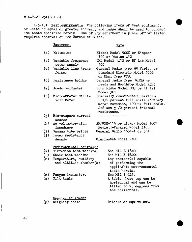
4.5.1.1 Test eauiument.- The following items of test equipment,●
or units of equal or greater accuracy and range shall be used to conduct~.hetests specified herein. Use of any equipment in place ofthat listealrequires approval of the Bureau of Ships.
(a)
(b)
(c)
(d)
(e)
(f)
(g)
(h)
(i)(j)
(k)(1)(m)
(n)(o)
Fquir)ment
Wattmeter
Variable frequencypower supplyVariable line trans-f0rmer
Resistance bridge
Ac-dc voltmeter
Microammeter milli-volt meter
Microampere currentsource
Ac voltmeter-highImpedance
Vacuum tube bridgePower resistancedecade
ZxeQ
Hickok Model 900C or Simpson390 or Weston 432OML Model 1430 or ~ Lab Model
500General Radio type W5Variac or
Standard Electric Model 500Bor Ghmi Type vT8.
General Radio Type 1652A orLeeds and Northrop Model 4735
John Fluke Model 803 or KintelModel 301.
Specially constructed, having a~1 /2 percent full scale accuracy
meter movement, 100 ua full scale,256 ~ti ~1/2 percent internalresistance.
---------------
AIJ/USM-l16 or Hickok Model 1601Hewlett-Packard Model 41OB
General Radio 1661-A or 561D
Clariostat Model 240C
Environmental eauiDmentVibration test machine See MIL-&l 64OOShock test maohine See MIL-E-16LO0Temperature, humidity Any chamber(s) capableand altitude chamber(s) of performing the
applicable environmentaltests herein.
Fungus incubator. See MIL-T-945.Tilt table A table whose top can be
horizontal and can be
Special eauioment(p) weighing scale
tilted to 75 degrees fromthe horizontal.
Datecto or equivalent.
42
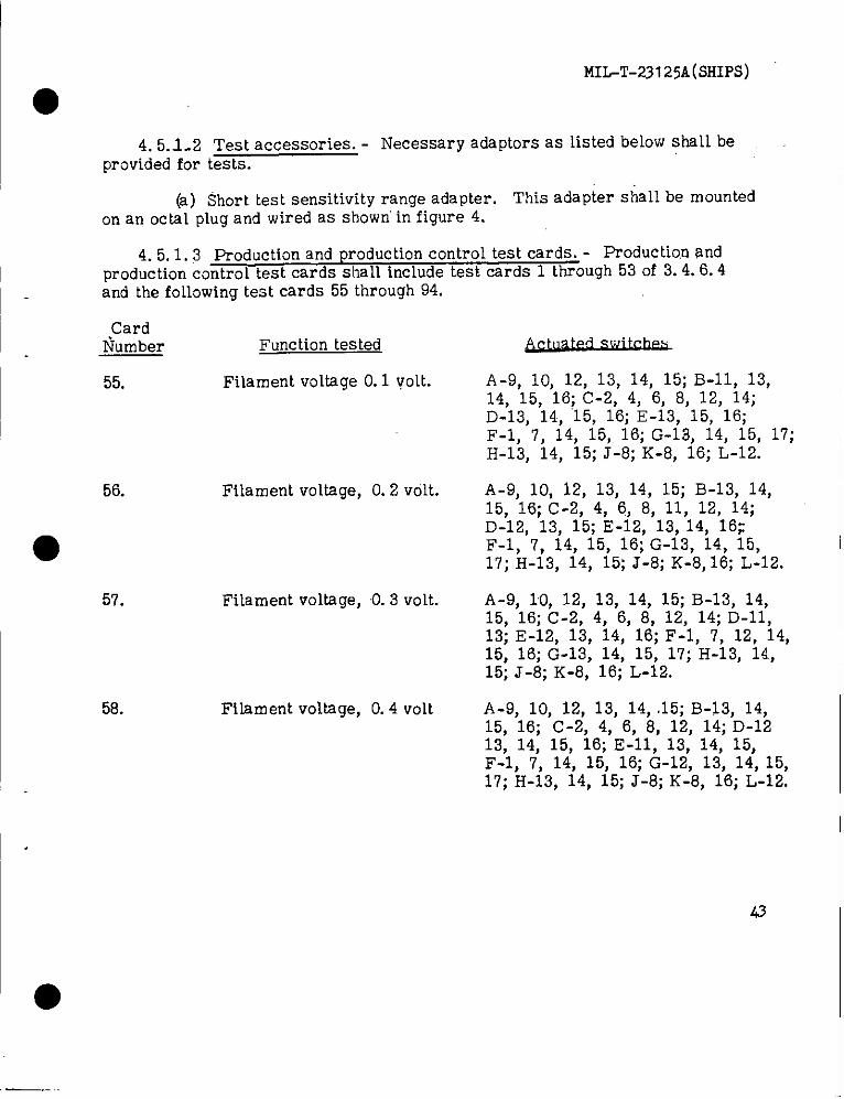
I
MIL-!K23125A(SHIPS)
●4. 5.1.2 Test accessories. - Necessary adaptors as listed below shall be
provided for tests.
(a) 5horttestsensitivityrange adapter. This adaptershallbe mountedon an octal plug and wired as shown’ in figure 4.
4. 5.1.3 Production and production control test cards. - Production andI production control test cards shall include test cards 1 through 53 of 3.4.6.4
and the following test cards 55 through 94.
CardNumber Functiontested
I 55. Filament voltage 0.1
56.
●
57.
58.
volt.
Filament voltage, O.2 volt.
Filament voltage, 0.3 vo~t.
Filament voltage, O.4 volt
~. .
A-9, 10, 12, 13, 14, 15; B-II, 13,14. 15. 16; C-2, 4, 6, 8, 12, “14;D-’13, ’14, ’15, i6; E-i3, “15, “16;F-1, 7, 14, 15, 16; G-13, 14, 15, 17;H-13, 14, 15; J-6; K-8, 16; L-12.
A-9, 10, 12, 13, 14, 15; B-13, 14,15, 16; C-2, 4, 6, 8, 11, 12, 14;D-12, 13, 15; E-12, 13, 14, 16;F-1, 7, 14, 15, 16; G-13, 14, 15>17; H-13, 14, 15; J-8; K-8, 16; L-12.
A-9, 10, 12, 13, 14, 15; B-13, 14,15, 16; C-2, 4, 6, 8, 12, 14; D-II,13; E-12, 13, 14, 16; F-1, 7, 12, 14,15, 16; G-13, 14, 15, 17; H-13, 14,15; J-8; K-8, 16; L-12.
A-9, 10, 12, 13, 14, .15; B-13, 14,15, 16; C-2, 4, 6, 6, 12, 14; D-1213, 14, 15, 16; E-ll, 13, 14, 15,F-1, 7, 14, 15, 16; G-12, 13, 14, 15,17; H-13, 14, 15; J-8; K-8, 16; L-12.
43
I●
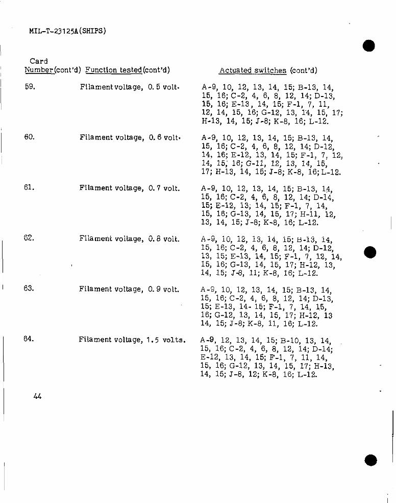
t.ilL-T-231 25A(.5HIpS)
CardNumber (cont’d) Function tested (cent’d)
59. Filament voltage, O.5 volt.
62.
II 63.
I 64.
60. Filament voltage, O.6 volt.
61. Filament voltage, O.7 volt.
Filament voltage, 0.8 volt.
Filament voltage, O.9 volt.
Filament voltage, 1.5 volts.
I 44
Actuated switches (cent’d)
A-9, 10, 12, 13, 14, 15;B-13, 14,15, 16;C-2, 4, 6, 8, 12, 14;D-13,15, 16; E-13, 14, 15;F-1, 7, 11,12, 14, 15, 16;G-12, 13, 14, 15, 17;H-13, 14, 15;J-8;K-8, 16;L-12.
A-9, 10, 12, 13, 14, 15;B-13, 14,15, 16;C-2, 4, 6, 8, 12, 14;D-12,14, 16;E-12, 13, 14, 15;F-1, 7, 12,14, 15; 16;G-n, 12, 13, 14, 15,17;H-13, 14, 15;J-8;K-8, 16;L-12.
A-9, 10, 12, 13, 14, 15; B-13, 1~,15, 16; C-2, 4,, 6, 8, 12, 14; D-14,15; E-12, 13; 14, 15; F-1, 7> 14,15, 16; G-13, 14, 15, 17; H-n, 12,13, 14, 15; J-8; K-8, 16; L-12.
A-9, 10, 12, 13, 14, 15;B-13, 14,15, 16;C-2, 4, 6, 8, 12, 14;D-12,13, 15;E-13, 1.4,15;F-1, 7, 12, 14,15; 16;G-13, 14, 15, 17;H-12, 13,14, 15; J-8, 11;K-8, 16; L-12.
A-9, 10, 12, 13, 14, 15; B-13, 14,15, 16; C-2, 4, 6, 8, 12, 14; D-13,15; E-13, 14- 15; F-1, 7, 14, 1.5,16; G-12, 13, 14, 15. 17: H-12. 1314; 15; J’-8; K-8; 11; 16;’ L-12.’
A-9, 12, 13, 14, 15;B-10, 13, 14,15, 16;C-2, 4, 6, 8, 12, 14;D-14;E-12, 13, 14, 15;F-1, 7> 11, 14,15, 16;G-12, 13, 14, 15, 17;H-13,14, 15;J-8, 12;K-8, 16;L-12.
●
_..L
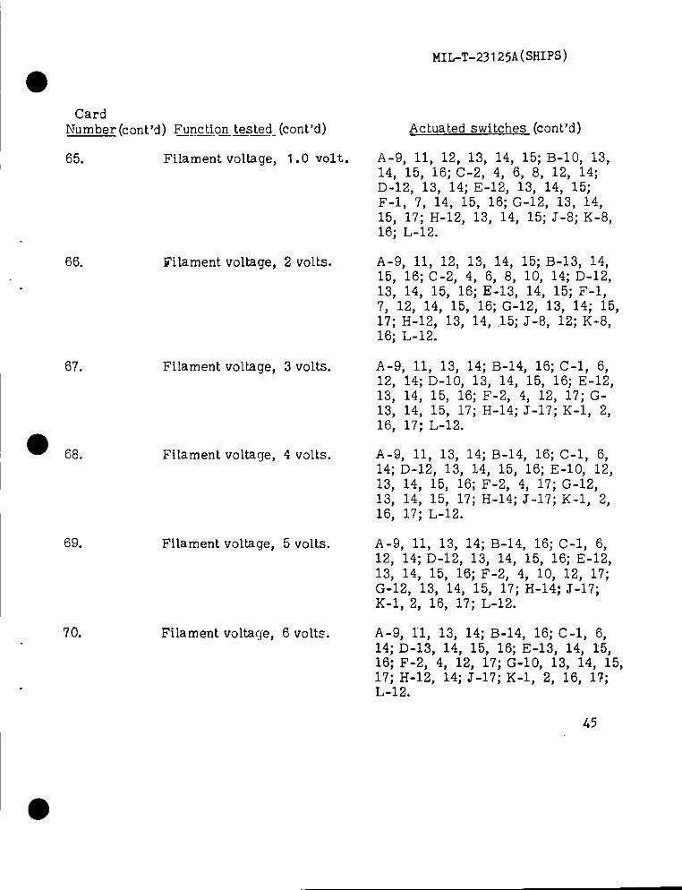
MIL-T-23125A(SHIpS)
●Card
Number (cent’d)Fflgctiontesteg.(cent’d)
65. Filament voltage,
66. Filament voltage,
69.
70.
Filament voltage,
Filament voltage,
Filament voltage,
1.0 volt.
2 volts.
3 volts.
4 volts.
5 volts.
Filament voltage, 6 volts.
Actuatedswitches (cent’d)
A-9, 11, 12, 13, 14, 15;B-10, 13,14, 15, 16;C-2, 4, 6, 8, 12, 14;D-12, 13, 14;E-12, 13, 14, 15;F-1, 7, 14, 15, 16;G-12, 13, 14,15, 17;H-12, 13, 14, 15;J-8;K-8,16; L-12.
A-9, 11, 12, 13, 14, 15; B-13, 14,15, 16; C-2, 4, 6, 8, 10, 14; D-12,13, 14, 15, 16; E-13, 14, 15; F-1,7, 12, 14, 15, 16; G-12, 13, 14; 15,17; H-12, 13, 14, .15; J-8, 12; K-8,16; L-12.
A-9, 11, 13, 14; B-14, 16; C-1, 6,12, 14; D-10, 13, 14, 15, 16; E-12,13, 14, 15, 16; F-2, 4, 12, 17; G-13, 14, 15, 17; H-14; J-17; K-1, 2,16, 17; L-12.
A-9, 11, 13, 14;B-14, 16;C-1, 6,14;D-12, 13, 14, 15, 16;E-10, 12,13, 14, 15, 16;F-2, 4, 17;G-12,13, 14, 15, 17;H-14; J-17;K-1, 2,16, 17; L-12.
A-9, 11, 13, 14;B-14, 16;C-1, 6,12.,14;D-12, 13, 14, 15, 16; E-12,13, 14, 15, 16;F-2, 4, 10, 12, 17;G-12, 13, 14, 15, 17;H-14; J-17;K-1, 2, 16, 17; L-12.
A-9, 11, 13, 14;B-14, 16;C-1, 8,14;D-13, 14, 15, 16;E-13, 14, 15,16;F-2, 4, 12, 17;G-10, 13, 14, 15,17;H-12, 14;J-17;K-1, 2, 16, 17;L-12.
f45
I ●
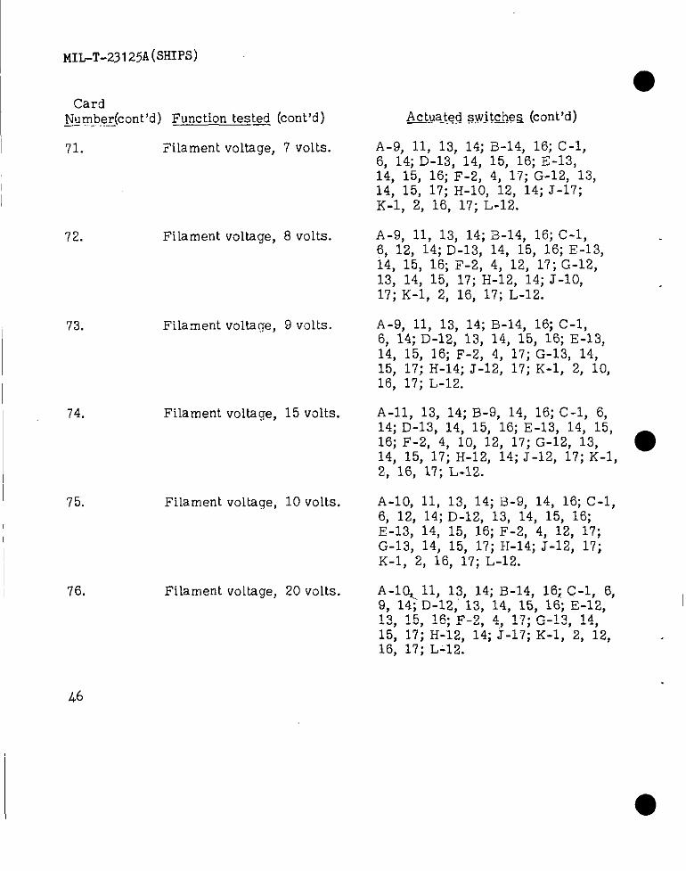
MIL-T-231 25A(S~pS)
CardNumber(ccmt’d) ~unction tested (cent’d)-- . .
71. Filament voltage, 7 volts.
72. Fi~ament voltage, 8 volts.
73. Filament voltage,9 volts.
74. Filament voltage,15 volts.
75. Filament voltage, 10 volts.
76. Filament voltage, 20 volts.
A&t.ua_ted.s,witinea(cent’d)
A-9, 11, 13, 14;B-14, 16;C-1,6, 14;D-13, 14, 15, 16;E-13,14, 15, 16;F-2, 4, 17; G-12, 13,14, 15, 17;H-10, 12, 14;J-17;K-1, 2, 18, 17; L-12.
A-9, 11, 13, 14;B-14, 16;C-1,6, 12, 14;D-13, 14, 15, 16; E-13,14, 15, 16; F-2, 4, 12, 17;G-12,13, 14, 15, 17;H-12, 14;J-10,17;K-1, 2, 16, 17; L-12.
A-9, 11, 13, 14;B-14, 16;C-1,6, 14;D-12, 13, 14, 15, 16; E-13,14, 15, 16; F-2, 4, 17;G-13, 14,15, 17;H-14; J-12, 17;K-1, 2, 10,16, 17; L-12.
A-11> 13, 14;B-9, 14, 16;C-1, 6,14;D-13, 14, 15, 16;E-13, 14, 15,16;F-2, 4, 10, 12, 17;G-12, 13, ●14, 15, 17;H-12, 14;J-12, 17;K-1,2, 16, 17;L-12.
A-10, 11, 13, 14; B-9, 14, 16;C-1,6, 12, 14;D-12, 13, 14, 15, 16;E-13, 14, 15, 16;F-2, 4, 12, 17;G-13, 14, 15, 17;H-14; J-12, 17;K-1, 2, 16, 17;L-12.
A-l C&n, 13, 14;B-14, 16;C-1, 6,9, 14;D-12, 13, 14, 15, 16; E-12, I13, 15, 16; F-2, 4, 17; G-13, 14,15, 17; H-12, 14; J-17; K-1, 2, 12, .16, 17; L-12.
(L6
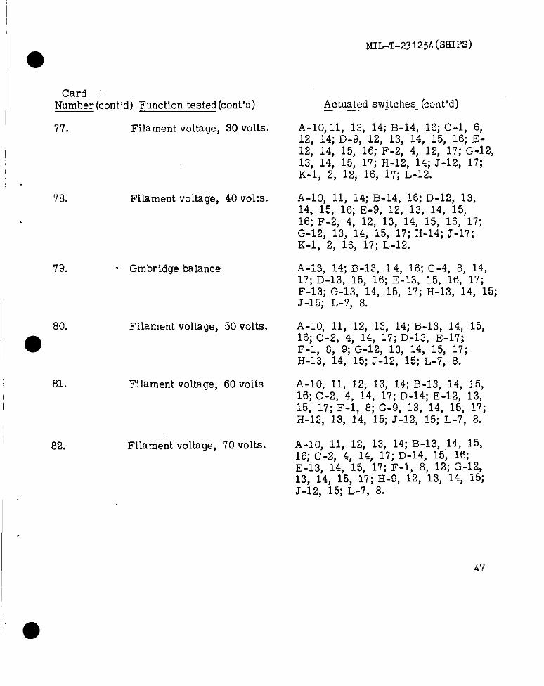
MIL-T-231 25A(SHIpS)
CardNumber (cent’d) Function tested (cent’d)
77. Filament voltage, 30 volts.
78. Filament voltage, 40 volts.
79. . Gmbridge balance
Filament voltage, 50 volts.
● 80”
81. Filament voltage, 60 volts
82. Filament voH.age, 70 volts.
Actuated switches (cent’d)—.
A-10, 11, 13, 14; B-14, 16; C-1, 6,12, 14; D-9, 12, 13, 14, 15, 16; E-12, 14, 15, 16; F-2, 4, 12, 17; G-12,13, 14, 15, 17; H-12, 14; J-12, 17;K-1, 2, 12, 16, 17; L-12.
A-10, 11, 14; B-14, 16; D-12, 13,14, 15, 16; E-9, 12, 13, 14, 15,16; F-2, 4, 12, 13, 14, 15, 16, 17;G-12, 13, 14, 15, 17; H-14; J-17;K-1, 2, 16, 17; L-12.
A-13, 14; B-13, 14, 16; C-4, 8, 14,17; D-13, 15, 16; E-13, 15, 16, 17;F-13; G-13, 14, 15, 17; H-13, 14, 15;J-15; L-7, 8.
A-10, 11, 12, 13, 14; B-13, 14, 15,16; C-2, 4, 14, 17; D-13, E-17;F-1, 8, 9; G-12, 13, 14, 15, 17;H-13, 14, 15; J-12, 15; L-7, 8.
A-10, 11, 12, 13, 14; B-13, 14, 15,16; C-2, 4, 14, 17; D-14; E-12, 13,15, 17; F-1, 8; G-9, 13, 14, 15, 17;H-12, 13, 14, 15; J-12, 15; L-7, 8.
A-10, 11, 12, 13, 14; B-13, ,14, 15,16; C-2, 4, 14, 17; D-14, 15, 16;E-13, 14, 15, 17; F-1, 8, 12; G-12,13, 14, 15, 17; H-9, 12, 13, 14, 15;J-12, 15; L-7, 8.
‘“●
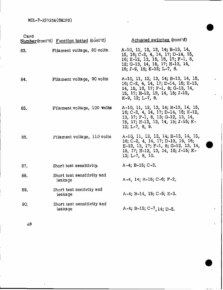
MIL-T-23125A(sHIPs)
I CardNumber (cent’d) Function tested (c~nt ‘d)
83. Filament voltage, 80 volts.
84. Filament voltage, 90 volts
85. Filament voltage, 100 volts
86. Filament voltage, 110 volts
87. Short tsst sensitivity.
88. Short test sensitivity andleakage
~ 89. Short test sentivity andleakage
90. Short test sensitivity andleakage
L8
Actuated switches (cent’d)
A-10, 11, 12, 13, 14; B-13, 14,15, 16; C-2, 4, 14, 17; D-14, 15,16; E-12, 13, 15, 16, 17; F-1, 8,12; G-13, ,14, 15, 17; H-13, 14,15; J-9, 15; K-12; L-7, 8.
A-10, 11, 12, 13, 14; B-13, 14, 15,16; C-2, 4, 14, 17; D-14, 15; E-13,14, 15, 16, 17; F-1, 8; G-13, 14,15, 17; H-12, 13, 14, 15; J-15,K-9, 12; L-7, 8.
A-10, 11, 12, 13, 14; B-13, 14, 15,16; C-2, 4, 14, 17; D-14} 15; E-12,13, 17; F-1, 8, 13; G-12, 13, 14,15, 17; H-12, 13, 14, 15; J-15; K-12; L-7, 8, 9.
A-10, 11, 12, 13, 14; B-13, 14, 15,16; C-2, 4, 14, 17; D-13, 15, 16;E-12, 13, 17; F-1, 8; G-12. 13, 14, ●15, 17; I-I-12, 13, 14, 15; J-15; K-12; L-7, 8, 10.
A-4; B-15; C-3,
A-4, 14;B-15; C-6; F-2,
A-4; B-14, 15; C-5; E-3.
A-4; B-15; C-7, 14; D.2.
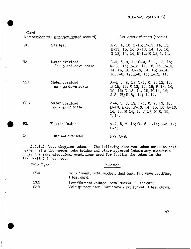
MIL-T-23 125A(SHIPS)
CardNumber (cent’d~F~gt.~Qu...tSteded.(COnt’d)
91. Gas test
92-1 Meter overloadGo up and down scale
92A Meter overloadno - go down scale
92B Meter overloadno - go up scale
● 93. Fuse indicator
$4. Filament overload
Actuatedswitche~ (cent’d)
A-3, 4, 16;c-16; D-13, 14, 15;E-13, 15; 16;F-13, 14, 15, 16;G-13, 14, 15;H-14; K-13; L-14.
A-4, 5, 6, 13;C-3, 6, 7, 13, 16;D-13,,16;E-13, 14, 15, 16;F-13,14, 15, 16;G-13, 14, 15;H-14,16;J-6, 17;K-6, 15;L-12, 14.
A-4, 5, 6, 13;C-3, 6, 7, 13, 16;D-15, 16; E-13, 15, 16;F-13, 14,15, 16;G-13, 14, 15;H-14, 16;J-6, 17;K-8, 15; L-14,
A-4, 5, 6, 13;C-3, 6, 7, 13, 16;D-16; L-16; F-13, 14, 15, 16;G-13,14> 15;H-14, 16;J-17;K-8, 15;L-14.
A-4, 5, 7, 16;C-15; H-14; K-5, 17;L-5;
F-9; G-9..
4.5.1.4 ‘fest electron tubes .- The following electron tubes shall be cali-brated using ths vacuum tube bridge and other approved laboratory standardsunder the same electrical conditions used for testing the tubes in theAN/lJSM-11~( ) test, set.
Tube Type Function
OZ4 No filament, octal socket, dual test, full wave rectifier,1 test card.
1B3 Low filamentvoltage,octalsocket,1 testcard.OA2 Voltageregulator,miniature7 pinsocket,4 testcards.

I MIL-T-23125A(fMIpS)
●Tube type (cent’d)
5U46A76AX46AL56CD6
6D66DT6
6J6
7TW12AX71213Y712AV62735W45(3C5
12CX6
8057026080
6111
Full wave rectifier, octal socket, 1 test card.Pentagrid converter, Large 7 pin socket, 2 test cards.Damper diode, octal socket, 1 test card.High perveance diode, miniature 7 pin socket, 1 test card.TV horizontal deflection amplifier, octal socket 2 test
card.Pentode, large 6 pin socket, 1 test card.Gating type pentode, suppressor test, miniature 7 pin
socket, 2 test cards.Dusl triode, both triodes operating, tniniature 7 pin
socket, 1 test card.Dusl triode, fixed bias, locktal socket, 1 test card.Dual triode, &ed ties miniature 9 pin socket, 1 test card.Pentode, high Gm, miniature 9 pin socket, 1 test card.Dual diode, miniature 7 pin socket, 2 test cards.Triode, fixed bias, 5 pin socket, 1 test card.Half-wave rectifier, miniature,. 7 pin socket, 1 test card.Power amplifier pentode, fixed bias, miniature 7 pin
socket, 1 test card.12 volt plate and screen pentode, miniature 7 pin socket,
1 test card.Full wave rectifier, 4 pin socket, 1 test card. ●Sub-miniature pentode inlinesocket, 1 testcard.Dusl triode, self bias, high current, octa~ socket, 3
test cards.Subminiature dual triode, subminiature 8 pin round
socket, 1 test card.
4. 5.2 Facilities. - The contractor shall furnish any additioml facilities,equipment and personnel required to assure that the equipment meets the
I requirements of this specification.
4. 5.3 Production inspection. - The production inspection specified hereinshall be performed on every unit delivered.
4.5. 3.1 Surface inspection. -high quality of:
Each production unit shall be. examined to assure
50
MIL-T-23i25A(SHIPS)
(a) VJorkmansl?ip, assembly and fit,mechanical safety and marking.(b) Materials, parts and finisi.
(c) Treatment for prevention of corrosion.(d) Accessibilityof components for replacement.
4.5.3.2 Specificoperating tests.- Each equipment shall be energized and
subjected to an operating test to insure qualitativelythe proper functioningofthe equipment and alloperating controls, hnd conformance with the safety re-quirements.
4. 5.3.2.1 Test equipment. - The following items of 4. 5.1.1 shall be usedfor production inspection:
(a) Microammeter, Mlllivoltmeter
(b) D. c . yoltmeter(c) Resistance bridge(d) A. c. voltmeter (high-impedance)(e) Variable line transformer (Variac)
4. 5.3.2.1.1 Test accessories. - The following items shall be used for● production inspection.
(a)b)
(c)
Calibration cell (3. 4. 6.2)Test cards 1, 2, 3, 4, 5, 6, 7, 8, 9, 10, 11, 12, 25, 52A, 53A,
87, 88, 89, 30, 91, 92-I, 92A,92B and 94 (3.4.6.4.3 and 4.5.1.3)Short testsensitivityran~e adapter (4.5.1.2)
4. 5.3.2.2 Test conditions. - Unless ot:~erwise specified herein all testsshall be performed under the following conditions.
(a) Ambient conditions. - The tests s lall be performed at factory orlaboratory atmospheric conditions.
(b) ,Input power. - The input power shall be 115 volts, 60 cps. a. c.(c) VJarmup. - The equipment shall be turned on and permitted to
warm up for. 5 minutes before any test is conducted.
51
MIL-T-23125A(SHIPS)
.4.5.3.3 Cell calibration.- The calibration cell to be provided ●as an accessory with the Squipment shall be tested as follows:
4.5.3.3.1 Cell current and voltaee.-
I (a)(b)
(c)
(d)
(e)
(f)
Connect pin number g to pin number 1 of the octal plug.Using the micmammeter, measure the current.between pinnumber 6 and pin number 1.The current shall be numerically equal, within 0.5
percent, to the “Press 2“ calibrationmrking on the cell.Using the millivolt meter measure the voltage fro!mpinnumber 7 to pin number 8.The voltage in millivolt shall be numerically equl,within O.5 percent, to the IvPress2 and 4~vcalihratj.onmarking on the cell multiplied by nominal meterresistance divided by 1000.Remove the connection between pins number 1 and number 8.
4. 5.3.3.2 Resistor calibration. -
(a) Using the resistance bridge connect the leads to pin number 1and pin number 3. The bridge shall measure 1 megohm ~ 5percent.
(b) Connect the bridge leads to pins number 1 and number 2 of theplug. The bridge shall measure 2 megohms + 5 percent. ●
(c) Connect the bridge leads to pins number 1 and n~mber 5 of theplug. The bridge shall measure 10 megohms ~ 5 percent.
(d~ Connect the bridge leads to pins number 1 and number 4 of theplug. The bridge shall measure 20 megohms ~ 5 percent.
4. 5.3.4 Equipment calibration and tests. -
4. 5.3.4.1 Meter calibration and short sensitivity tests. - These tests
Ishall be conducted using the calibration cell (3.4. 6. 2).
4. 5.3.4.1.1 Meter calibration. - The meter calibration shall be listedin the following manner:
I 52
● I
I
,

MIL-T-23125A(SHIpS)
(a) Insert calibration card number 1, meter, into the switch. Plugthe calibration cell into the octal test socket. The number 1Short lamp (countingfrom left to right) and the !!Repeat Tests!’lamp shall glow.
(b) F?ress button number 2 for check of meter microamp cal. Themeter shouM read within + 1 division of the figure written inthe top blank on the calibr~tion celi cover. If the reading isout of tolerance the meter shouId be checked against a meterstandard for 50 Vam P indication at mid-scale. If the error is
signi~lcant, the meter should be replacsd.(c) Hold down button number 2 and press button number 4 to check
meter millivolt sensitivity . The meter should read within+ 1 division of the figure written in the bottom blank on the
calibration cell cover. If the reading is out of tolerance,adjust the “METER CAL” control for proper reading (locatedin” the auxiliary control compartment).
4. 5.3.4.1.2 Short sensitivity test. - Maintain cell in test socket.
(a) Insert calibration card number 2, SHORTS 2 MEG. NO-GO.Observe that no short lamps are lighted. If any lamps
●are glowing adjust”LO SENS” short test control to justextinguish a 11 lam ps.
(b) Insert card number 3, SHORTS 1 MEG GO. The left fourIamps should glow. If they are not glowing re-adj ust theLO SENS control until they glow with card number 3 andare extinguished with card number 2, as listed above.
(c) Insert card number 4, SHORT 20 MEG NO-GO. PressSENSITTVE GRID SHORTS butiton located in the auxiliarycompartment. No short lamps should glow. (If any arelighted adjust the Hf SENS control).
(d) Inser card number 5, SHORT 10 MEG CO. Press SENSITIVE&GR SHORTS button located in the auxiliary compartment.
The number 4 lamp only (counting left to right) should glow.NOTE: The lamp may flicker or glow dimly as compared tothe LO SENS short indication. If the number four lamp isnot glowing re-adjust the HI SENS control until it gLows withcard number 5 and is extinguished with card number 4, asbefore.
53
●

MIL-T-23125A(SHIPS)
(e) Remove calibration cell from octal socket.
4. 5.3.4.2 Negative fixed bias. - The negative fixed bias shall be testedin the following manner,
(a) Insert card number 6, FEED BIAS CAL NEG. No short lampsshould glow.
(b) Press button number 2. Meter should read half scale. Ifreading is other than half scale, adjust “BIAS CAL NEG”control for proper indication.
(c) Test tolerances 49 to 51 divisions.
4. 5.3.4.3 Positive fixed bias. - The positive fixed bias shall be testedin the following manner.
(a) Insert card number 7. FIXED BIAS CAL POS. Short lamps 1and 2 should glow.
(b) Connect the d. c. voltmeter from pin number 3 to pin number6 of the octal socket with the positive meter lead to pinnumber 3. Any meter reading observed should be disregarded.
(c) Press button number 2, the d. c. voltmeter should read 7.5 voltsand the panel meter shall indicate 49 to 51 divisions. ●
(d) If the d. c. voltmeter reading is not proper, adjust “BIAS CALPOS” control (located in the auxiliary control compartment)for correct indication.
4. 5.3.4.4 Main B plus power su ~- The’ main B plus suppIy shall betested in the foTlow mg wanner.
(a)
(b)
(c)
Insert card number 8,MAIN B PLUS CAL. Short lamps 1, 2, 3and 5 should glow.
Maintain the d. c. voltmeter connections as in step (b) of4..5.3.4.3.
Fress button number 2, the d. c. voltmeter should read 20 voltsand the panel meter shall indicate 49 to 51 divisions.
5L
— .—
● ✌(d)
(e)
(f)
(9)
MIL-T-23125A(SHIPS)
If the d. c. voltmeter reading is not proper, adjust the MAINB PLUS CALcontrol (located in the auxiliary compartment)for correct indication.
Insert card number 23, MAIN B PLUS REG. Short lamps 1,2, 3 and 5 should glow.
Press button number 2. The pnel meter shall indicate 48 to52 divisions. Note the exact reading.
Fress buttons number2 and number 4. The meter shallindicatetheexactreadingofstep (f)~ 1 division.
4. 5.3.4.5 GM circuit balance. - The Gm circuit shall be tested in Uaefollowing manner. Check that the white dots on the Gm BAL RI lb and LO lbknobs are in line with the associated dots labeled NOM (Nomina~on the panel,
(a)
(b)
●4.5.3.4.
Insert card number 9 GM BAL LOW IB. Press button number 2.Meter should read zero, + 3 divisions or minus the equivalentof 3 divisions. If the reading is out of tolerance of LO lbcontrol may be adjusted for a zero reading and the knob reseton the control shaft to properly align the dots.
Insert card number 10, GM BAL HI IB. Press button number 2.The meter should read zero, + 3 divisions or minus the equivalentof 3 divisions. If the reading is out of tolerance the HI Ib controlmay be adjusted in manner noted for LO Ib above.
6 Signa 1 supply voltage. - The signal supply voltage shall be testedin the following manner.
(a) Connect theequipment to the power line through a variac andmonitor the voltage delivered to the instrument with an a. c.voltmeter.
(b) Connect a high-impedance a. c. voltmeter from pin number 3to pin number 6 of the octal socket.
(c) Insert card number 11, SIG, REG and AMP. Short lamp 1 shouldglow.
(d) Check for regulation of the signal supply voltage by holdingdown button number 2 and varying the line voltage from 105to 125 VOltS. Note reading indicated onmeter. The indicated voltage at 105 andidentical and shall not vary more than 1indicated voltage at 115 voltg line.
the high-impedance125 should bepercent from the
55

MIL-T-23125A(SHIP5)
(e) If the circuit is not regulating (variesmore than 1 percent)as an item (b), adjust ths SIGNAL CAL FCMULATION controlsnd vary the line voltage to attain the desired regulation.
(f) After the signal regulation is properly adjusted, set the exactlevel of O.222 volt rms by adjusting the SIGNAL CAL AMPLITUDEcontrol.
4. 5.3.4.7 Filament standardization. - The filament standardization shsllbe tested in the following manner.
(a)
(b)(c)
(d)
(e)
(f)
(9)
(h)
(i)
Maintaining the variac and a. c. voltmeter connections as in steps(a) and (b) of 4.5.3.4.6, set the line voltage to 115 volts.
Insert card number 12, FIIAMENT STD: ADJUSTMENT.Set the FIL4 MENT STD. ADJUSTMENT located in the auxiliary
control compartment, to the NOM 115v position (white dot onknob lines up with dot on panel). The high-impedance voltmetershould read 4.95 to 5.05 vOlts.
Press the FILAMENT STD. ADJUSTMENT push button. The Pnelmeter shall indicate 50 divisions.
If correction is necessary, adjust the FILAMENT STD. CALcontrol located in the upper right corner of the control compart-ment, for proper indication of 50 divisions.
Insert test card number 24 in the program switch. Cathode toplate short indication shall occur. ●
Actuate test switch number 2. The panel meter shall indicate47 to 53 divisions. The exact reading shall be noted.
Actuate the cathode activity test switch in the auxiliary compart-ment. The cathode activity test warning lamp on the main pmelshall light.
Actuate test switch number 2. The panel meter shall read 4 to 6divisions lower than the reading noted in (g) above.
4. 5.3.4.8 Auxiliary B plus power supply. - The auxiliary B plus powersupply range shall be tested as follows:
(a) Install test card number 25, auxiliary B plus reg. Short lamps1, 2, 3 and 5 shall glow.
(b) Actuate the auxiliary B plus read switch in the auxiliary compar-tment, vary the auxiliary B Plus range control in the auxiliarycompartment. and observe that the meter reading can be variedfrom less than 10 to more than 100 scale divisions.
56
I
I
MIL-T-23125A(SHIPS)
(c) Set the auxiliary E plus range control for a reading of 50divisions.
(d) Release the auxiliary B plus read button and actuate button number2. The meter shall read 49 to 51 divisions.
(e) Press button number 4 while “Iolding down button number 2. Themeter indication shall change less than 3 division from theindication obtained with only button actuated.
4. 5.3.4.9 Overload protection. - Overload protection shall be tested inthe following manner.
(a)
(b)
(c)
(d)(e)(f)
(9)
(h)
Insert test card number 52A, relay, No Go. Short lamps 1 and2 shall glow.
Actuate test switch number 2. The equipment overload deviceshall not operate.
Insert test card number 53A, relay Go. Short lamps 1 and 2 shaHglow. Cathode to suppression grid short indication shall occur.
Actuate test switch number 2. The overload device shall operate.Restore equipment opera tion.Insert test card number 92-1 meter overload. Disregard anydoting short lamps.
Observe the meter pointer while actuating test switch number 2.The meter pointer shall move beyond full scale and the overloadprotective relay shall operate.
Restore equipment opera tion.fij Observe the meter Dointer while actuatinq test switches number 4.,
0)(k)0)
and 2 simultaneously. The meter shall move down-scale fromzero and the overload protective reiay shall operate.
Restore equipment operation.Install test card number 92A.Fress test buttons number 2 and 4 simultaneously. The meter
pOiII& shal~ move dowmscale from zero and the overload relayshallnot operate.
(m) Remove test card number 92A and install test card number 92B.(n) press test button number 2. The meter pointer shall move beyond
full scale and the overload relay shall not operate.(o) Insert test card number 94, FIL OVERLOAD. The 100 watt iamp
shall light at once. This lamp is located under the front paneland shaU be observed through an opening in the auxiliary controlcompartment.
57
t4n,-T-231 25A(SHIPS)
4.5.3.4.10 Shorts and leakage test. - The shorts and leakage test shall betested in the following manner.
(a) Installtheshorttestsensitivityrange adapter (4. 5.3.4.1. 2) inthe octal test socket.
(b) Insert card number 87. Short lamps 1, 2, 3 and 4 shall glow.(c) Insert card number 88. Short lamps 1, 2 and 3 shall glow and
the pnel meter shall indicate 8 to 12 divisiona.(d) Insert card number 89. Short lamps 1 and 2 shall glow and the
panel meter shall indicate 8 to 12 divisions.(e) Insert card number 90. Short lamp 1 shall glow and the panel
meter shall indicate 8 to 12 divisions.
4.5.3.4.11 Gas test. - The gas test shall be tested in the following manner.
(a) Insert card number 91, gas test. Short lamps 1, 2, 3 and 4 shallglow .
(b) F?ress button number 3 and the meter shall indicate 45 to 55divisions.
4.5.3.4.12 Electron tube tests. - The electron tubes of 4.5.114 shall betested in the equipment. The readings on the O to 100 scale shall be within 5percent of the calibration values plus the correction of figure 1 and the readings ●shall be repea~ble of aH eq~ipments withh 3 percent.
4.5.4 Production control inspection. - Production control inspection shallbe conducted on a random sampling basis in accordance with the sampling planspecified herein. This inspection shall comprise such examination and testingas will prove satisfactory performance throughout the entire range of operation,detect deterioration of the design or deviations from approved processing ofmaterials and demonstrate that the equipment will function satisfactorily underadverse conditions.
4, 5.4.1 ,3ampling pkq. - From each lot which has passed the productioninspection, a ranciom sample of units shall be selected as specified and shall besubjected, to production control inspection. The number selected and lotacceptance level shall be based on table III. Reduced inspection may be instf’tutedat the discretion of the, inspector when the manufacturer has met the requirementsstated in MIL-STD-105.
58
L
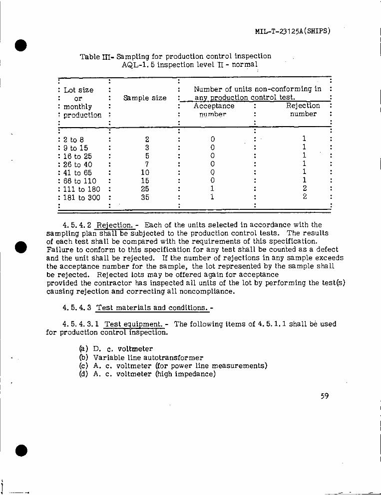
MIL-T-23125A(SHIPS)
Table In- Ssmpling for production Control inspectionAQL-1. 5 inspection level “E- normal
: Lot size : : Number of units non-conforming in :: or Sample size : any Preduction control test.: monthly : Acceptance : Rejection :: production : number number :
:2t08 2 0 :. 1:9to15 : 3 o“: 1:16t025 : 5 0 1:26t040 : 0 1:41t065 : 1: 0 1:66 to 110 : 15 0 1:111 to 160 : 25 1 2:181 to 300 : 35 1 2
4. 5.4.2 Rejection. - Each of the units selected in accordance with thesampling plan shall be subjected to the production control tests. The resultsof each test shall be compared with the requirements of this specification.
● Failure to conform to this specification for any test shall be courited as a defectand the unit shall be rejected. If the number of rejections in any sample exceedsthe acceptance number for the sample, the lot represented by the sample shallbe rejected. Rejected lots may be offered again for acceptanceprovided the contractor has inspected all units of the lot by performing the test(s)causing rejection and correcting all noncom p~iance.
4. 5.4.3 Test materials and conditions. -
4. 5.4.3.1 Test equipment. - The following items of 4. 5.1.1 shall be usedfor production control inspection.
(a) D. C. voltmeter(b) Variable line autotransformer(c) A. c. voltmeter (for power line measurements)(d) A. c. voltmeter (high impedance)
59
-.—— . —-— .

MIL-T-23125A(sms)
I
(e) Wattmeter(f) Variable frequency power source
4.5.4. 3.2 Test accessories and test cards. - The following item of 3.4.6and 4. 5.1.3 shaIl be used for production control inspection.
(a) Calibration cell (3. 4.6. 2)(b) Test cards 1, 11, 12, 15 through 51, 55 through 86, 93.
4. 5.4.3.3 Test conditions. - Unless otherwise specified herein, testconditions shall be the same as specified in 4.5.3.2.2.
4. 5.4.4 Specific production control tests. -
4. 5.4.4.1 Meter circuit test. -
4. 5.4.4.1.1 Meter calibration. - The meter calibration shall be tested asfoklows:
(a)b)(c)
(d)
Installthecalibrationcellin theoctaltestsocket.Inserttestcard number 1 in theprogram switch.Actuatetestswitchnumber 2. The meter shallindicatewithin1divisionthecurrentcalibrationvaluemarked on thecell.
Actuatetestswitchesnumber 2 and number 4. The meter shallindicatewittdn1 divisionof thedivisionsvalue marked on thecell.
4. 5.4.4.1.2 Meter shunts and multipliers. - The meter shunts and multipliersshall be tested using the cards listed herein. Actuating test switch number 2 aftereach test card is inserted shall give a meter indication of 48 to 52 divisions.
I
60
●
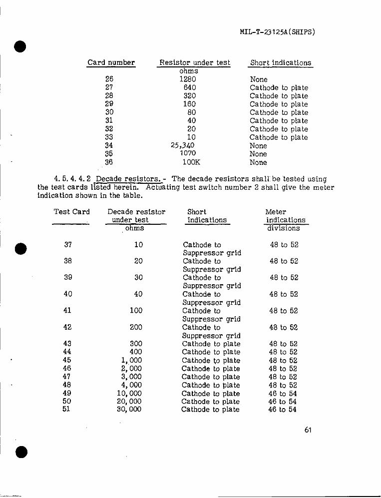
MIL-T-23 125A(SHIPS)
Card number
2627282930313233343536
Resistor under testohms1280
640320160
80402010
25,3401070lOOK
Short indications
NoneCathode to plateCathode to plateCathode to plateCathode to plateCathode to plateCathode to plateCathode to plateNoneNoneNone
4. 5.4.4.2 Decade resistors. - The decade resistors shall be ‘tested usingthe test cards listed herein. Actosting test switch number 2 shsll give the meterindication shown in the table.
Test Card
● 3’38
39
40
41
42
::45464748495051
Decade resistorunder test
ohms
10
20
30
40
100
200
300400
1,0002,0003,0004, (MO
10,00020,00030,000
Shortindications
Cathode toSuppressor gridCathode toSuppressor gridCathode toSuppressor gridCathode toSuppressor gridCathode toSuppressor gridCathode toSuppressor gridCathode to plateCathode to plateCathode to plateCathode to plateCathode to plateCathode to plateCathode to plateCathode to plateCathode to plate
Meterindicationsdivisions
46 to 52
46 to 52
48 to 52
48 to 52
48 to 52
48 to 52
48 to 5248 to 5248 to 5248 to 5248 to 5248 to 5246 to 5446 to 5446 to 54
61
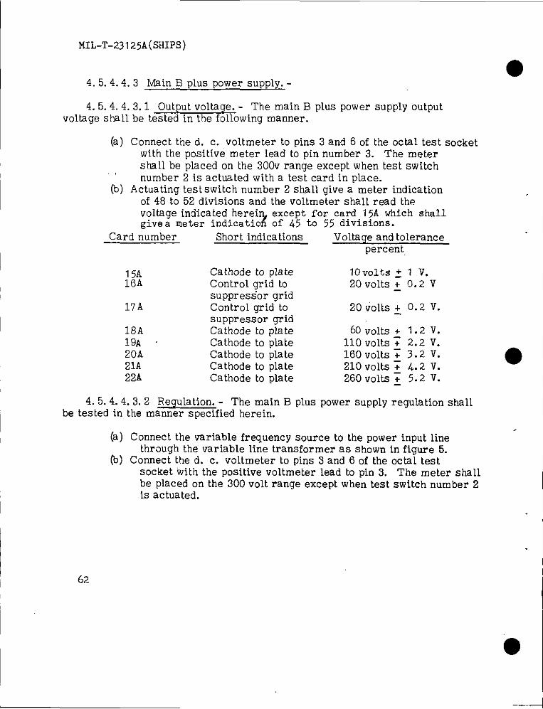
MIL-T-23125A(sH1Ps)
●4.5.4.4.3 Main B pluspower supply.-
4.5.4.4.3.1 Outputvoltage.- The main B plus power supply outputvoltage shall be tested in the following manner.
(a) Connect the d. c. voltmeter to pins 3 and 6 of the octal test socketwith the positive meter lead to pin number 3. The metershall be placed on the 300v range except when test switchnumber 2 is actuated with a test card in place.
(b) Actuating test switch number 2 shall give a meter indicationof 48 to 52 divisions and the voltmeter shall read the
give.a meter indicatio% of’ .L5 to 55 divisions.voltage indicated herei except for card 15A which shall
Card number Short indications Voltage and tolerancepercent,
15A Cathode toplate lovolts ~ 1 v.16A Controlgrid to 20 volts~ 0.2 v
suppressor grid17A Control grid to 20 volts + 0.2 v.
suppressor grid18A Cathode to plate 60 volts + 1.2 V.19A Cathode toplate 110 volts7 2.2 v.20A Cathode toplate 160 volts~ 3.2 V.21A Cathode toplate 210 volts~ 4.2 V.22A Cathode toplate 260 volts~ 5.2 V.
4.5.4.4.3.2 Regulation.- The main B plus power supply regulation shallbe tested in the manner specified herein.
(a) Connect the variable frequent y source to the power input linethrough the variable line transformer as shown in figure 5.
(b) Connect the d. c. vo~tmeter to pins 3 and 6 of the octal testsocket with the positive voltmeter lead to pin 3. The meter shallbe placed on the 300 volt range except when test switch number 2is actuated.
I62
● I
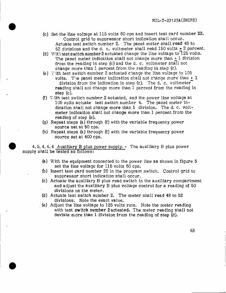
MIL-T-23125A(SHIPS)
(c) Set the line voltage at 115 volts 60 cps and insert test card number 23.Control grid to suppressor short indication shall occur.
Actuate test switch number 2. The panel meter shaH read 48 to52 divisions and the d. c. vottmeter shall read 150 volts + 2 percent.
(d) Wit:~test switch number2 actuated change the line voltage to~25 vo~ts.The panel meter indication shall not change more than ~ 1 divisionfrom the reading in step (c) and the cl. c. voltmeter shall notchange more than 1 percent frbm the reading in step (c).
(e) ‘J”ith test switch number 2 actuated change the line voltage to 105volts. Tile Wnel meter indication shall not change more than + 1
division from the indication in step (c). The d. c. voltmeter-readinq shall not change more than 1 percent from the reading instep (cj.
(f) K ith test switch number 2 actuated, and the power line voltage at105 volts actuate test switch number 4. The panel meter in-dication shall not change more than 1 division. The d. C. volt-meter indication shall not change more than 1 percent from thereading of step (e).
(g) Repeat steps (a) through (f) with the variable frequency powersource set at 50 cps.
(h) Repeat steps (a) through (f) with the variable frequency powersource set at 400 cps.
● 4.5.4.4.4 Auxiliary B plus power supply. - The auxiliary B plus powersupply shall be tested as follows:
(a)
(-b)
(c)
(d)
(e)
W’ith the equipment connected to the power line as shown in figure 5set the line voltage for 115 volts 60 cps.
Insert test card number 25 in the program switch. Control grid tosuppressor short indication ‘shall occur.
Actuate the auxiliary B plus read switch in the auxiliary compartmentand adjust the auxiliary B plus voltage control for a reading of 50divisions on the meter.
Actuate test switch number 2. The meter shall read 48 to 52divisions. Note the exact value.
Adjust the line voltage to 125 volts rms. Note the meter readingwith test switch number 2 actuated. The meter reading shall notdeviate more than 1 division from the reading of step (d).
63
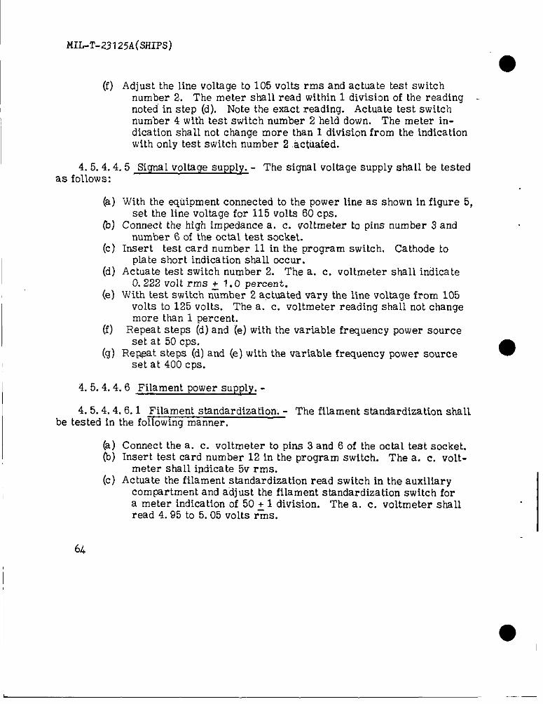
MIL-T-23 125A(SHIPS)
I
(f) Adjust the line voltage to 105 volts rms and actuate test switchnumber 2. The meter shall read within 1 division of the readingnoted’ in step (d). Note the exact reading. Actuate test switchnumber 4 with test switch number 2 held down. The meter in-dication shall not change more than 1 division from the indicationwith only test switch number 2 .ac~uated.
4.5.4.4.5 Signal voltage supply. - The signal voltage supply shalI be testedas follows:
(a)
0)
(c).
(d)
(e)
(f)
(9)
With the equipment connected to the power line as shown in figure 5,set the line voltage for 115 volts 60 cps.
Connect the high impedance a. c. voltmeter to pins number 3 andnumber 6 of the octal test socket.
Insert test card number 11 in the program switch. Cathode toplate short indication shall occur.
Actuate test switch number 2. The a. c. voltmeter shall indicate0.222 volt rms ~ 1.0 percent.
W’ith test switch number 2 actuated vary the line voltage from 105volts to 125 volts. The a. c. voltmeter reading shall not changemore than 1 percent.
Repeat steps (d) and (e) with the variable frequency power sourceset at 50 cps.
Re~at steps (d) and (e) with the variable frequency power source ●set at 400 cps.
I 4. 5.4.4.6 Filament power supply. -
4. 5.4.4.6.1 Filament standardization. - The fibment standardization shallbe tested in the following manner.
~(a) Connect the a. c. voltmeter to pins 3 and 6 of the octal test socket.(b) Insert test card number 12 in the program switch. Thea. c. volt-
meter shall ipdicate 5V rms.(c) Actuate the filament standardization read switch in the auxiliary
compartment and adjust the filament standardization switch fora meter indication of 50 + 1 division. The a, c. voltmeter shallread 4.95 to 5.05 volts r-ins.
6L
●I
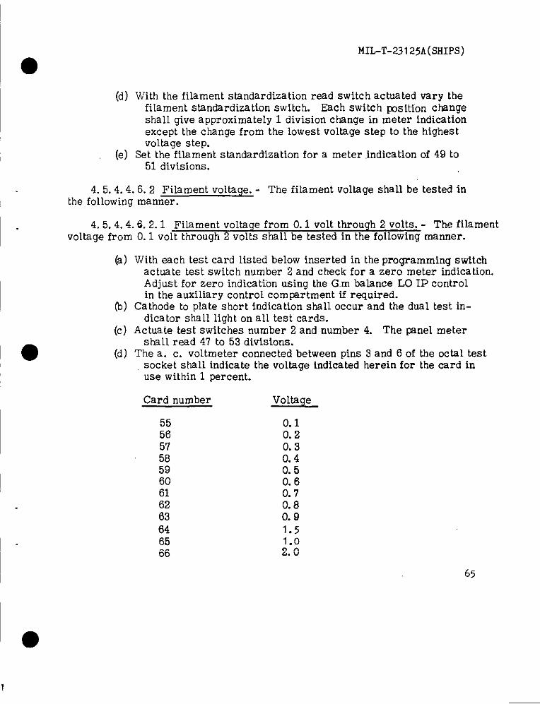
MIL-T-2S125A(SHIPS)
I ●
I
(d) With the filament standardization read switch actuated vary thefilament standardization switch. Each switch ~sitfon changeshall give approximately 1 division change in meter indicationexcept the change from the lowest voltage step to the highestvoltage step.
(e) Set the filament standardization for a meter indication of 49 to51 divisions.
4. 5.4.4.6.2 Filament voltage. - The filament voltage shall be tested inthe following manner.
4. 5.4.4.6.2.1 Filament voltxge from 0.1 volt through 2 volts. - The filamentvoltage from O.1 volt through 2 volts shall be tested in the following manner.
(a) With each test card listed below inserted in the pro~amming swttchactuate test switch number 2 and check for a zero meter indication.Adjust for zero indication using the G.m balance LO 1P controlin the auxiliary control compartment if required.
(b) Cathode to plate short indication shall occur and the dual test in-dicator shall light on all test cards.
(c) Actuate test switches number 2 and number 4. The pnel metershall read 47 to 53 divisions.
(d) The a. c. voltmeter connected between pins 3 and 6 of the octal testsocket shall indicate the voltage indicated herein for the card inuse within 1 percent.
Card number
555657585960616263646566
&E!&0.10.20.30.40.50.60.70.80.91.5
65
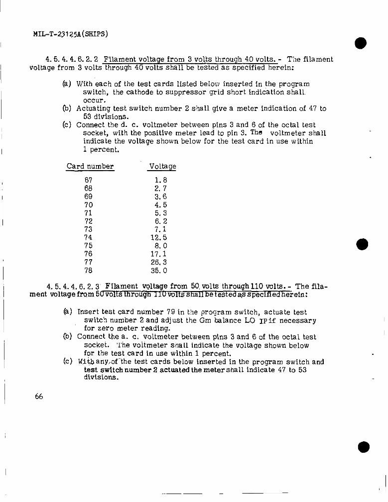
MIL-T-231 z5A(sHIPs)
I
4.5. 4.4.6.2.2 Filament voltage from 3 volts through 40 volts. - The filamentvoltage from 3 volts through 40 volts shall be tested as specified herein:
(a) With each of the test cards listed below inserted in the programswitch, the cathode to suppressor grid short indication shall.occur.
(b) Actuating test switch number 2 shall give a meter indication of 47 to53 divisions.
(c) Connect the d. c. voltmeter between pins 3 and 6 of the octal testsocket, with the positive meter lead to pin 3. Tha voltmeter shallindicate the voltage shown below for the test card in use within1 percent.
Card number -l@@
67 1.868 2.7’69 3.670 4.571 5.372 6.273 7.174 12.575 8.076 17.177 26.378 35.0
4.5.4.4.6.2.3’ Filament voltage from 50, volts through 110 volts. - The fila-ment voltage from 50 volts through 11u volts shall be tested@ specified erein:
(a) Insert test card number 79 in the program switch, actuate testswitch number 2 and adj uat the Gm balance LO IP if necessaryfor zero meter reading.
(b) Connect the a. C. vo~tmeter between pins 3 and 6 of the octal testsocket. The voltmeter s’hall indicate the voltage shown belowfor Me test card in use within 1 percent.
(c) IJjtb any.of’’the test cards below inserted in the program switch andtest switch number 2 actuated the meter shaU indicate 47 to 53divisions.
66

MIL-1’-23I25A(sH1ps)
Card number Voltage’’, . . .,).
80 5081 60 ,,, .82 7083 8084 9085 10086 110
4.5.4.4.7 Blown fuse indicators. - The blown fuse indicators shall betested as specified herein:
(a) Remove the d. c. filament fuse, Gm bridge fuse, and auxiliaryB plus fuse.
(b) Insert test card number 93 in the program switch. Cathod6 toplate short indication shall occur.
(c) Actuate test switch number 2 and observe that the three blownfuse indicators light.
4. 5.4.4.8 Power consumption tests. - The total wattage of the equipmentshall be tested as specified herein:
(a)
b)
(c)
Connect the equipment to the 115 volt 60 cycle power line throughthe wattmeter.
With no card insertedand theequipment on thepower shallnotexceed 80 watts.
With testcard number 52A installedandtestswitchnumber 2actuated the power shall not exceed 215 watts.
4. 5.4.4.9 Weiaht and dimensions.-The weight and size shall be measuredas specified hereinafter:
(a) Weighi the equipment including all accessories. The weight shallnot exceed 50 pounds.
b) Measure the squipment as required by, 3.6.1. The dimensions shallnot exceed the requirements of 3.6.1.
4.5.5 .~ddi:ional qualification test ~ Unless otherwise spec.if ied, the followingtests shall be performed only on the four qualification models. These tests shallbe conducted after successful conclusion of the production and preprodhction Controltests of 4. 5.3 and 4.5.4.
67
I ●
.-— -
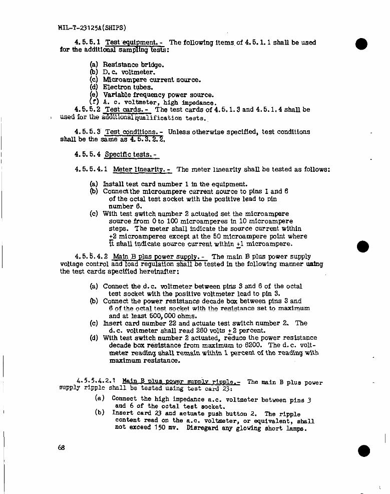
MILT-231 25A(smps)
4.5.5.1 Test equipment. - The following items, of 4.5. L 1 shall be usedfor the additional sampllng tests:
(a) Resistance bridge.(b) D. c. voltmeter.(c) Microamwre current source.(d) Electron tqbes.
E\ ~~:$f’~u~cYPQww SOU?W.oltieter, high lm.pedence.4.5.5.2 Test cards. - The test cards of 4.5.1.3 and 4.5.1.4 shall be
used for the additional lpalification tests.
4.5.5.3Test conditions. - Unless otherwise specified, test conditionsshall be tie same as 4.5.3.2.2,
4.5.5.4Specific tests. -
4.5.5.4.1Meter linearity. - The meter linearity shall be tested as follows:
(a) Install test card number 1 tn the equipment.~) co~e~the microampere current source to pins 1 and 6
of the octal test socket with the Wsitive lead to pinnumber 6.
(c) With test switch number 2 actuated set the microampereeource from Oto lCOmicroampere in 10 microamperesteps. The meter shall indicate the source current within:2 microampere except at the 50 microsmpme ~tnt whereit shall i!dlcate source torrent withh ~1 microampere.
4.5. ~. 4.2 Mafn B Plus power supply. - The main B Plus Pwer supplyvoltage control and load regulation shall be tested in the following manner o@ngthe test cards specified hereinafter:
(a) Connect the d. c. voltmeter between phis 3 and 6 of the octaltest socket with the positive voltmeter lead to pin 3.
(b) conned the power resistance decade b= between pins 3 and6 of the octal test socket with the resistance set to maximumand at least 500, 000 ohms.
(c) Insert card number 22 and actuate test switch number 2. Thed. c. voltmeter shall read 260 volts :2 percent.
(d) With test switch number 2 actuated, reduce tie power resistancedecade bos resistance from maximum to 6200. The d. c. volt-meter reading shall remain within 1 percent of the reading withmsximum resistance.
4.5.5 .4.2.1 l%alnB Dlua rmwer mDDly riuule. - The main B plus powersupply ripple shell be tested using test card .23:
(a) connect the high impedance a. c. voltmeter between pInS 3and 6 of the octal test socket.
(b) Insert card 23 and actuate push button 2. The ripplecontent read nn the a. c. voltinater, or equivalent, shallnot esceed 150 mv. Msreganf any glowing short lamps.
68
. - —.. -
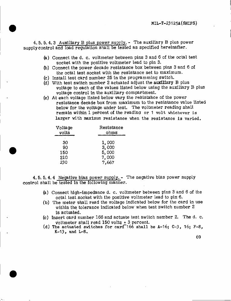
MIL-T-23125A(SHIPS)
4. 5.5.4.3 Auxiliary B plus power supply. - The auxi~iary B plus power
supply control and bad regulation stml~ be tested as specified hereinafter.
(a)
(b)
(c)(d)
(e)
4.5.5.4.
Connect the d. c. voltmeter between pins 3 and 6 of the octal testsocket with the positive voltmeter lead to pin 3.
Connect the power decade resistance box between pins 3 and 6 ofthe octal test socket with the resistance set to maximum.
InstsU test card number 25 in the programming switch.With test switch number 2 actuated adjust the auxflfary B plus
voltage to each of the values listed below using the auxiliary B plusvoltage control in the auxiliary compmtment.
At each voltage listed below vary the resistance of the powerresistance decade box from maximum to the resistance vahe listedbelow for the voltage. under test. The voltmeter reading shallremain within 1 percent of the reading or 1 volt whichever islarger with waximum resistance
Voltage Resistancevolts ohms
30 1,00090 3,000
150 5,000210 7,000230 7,667
when the resistance is varied.
4 Ne’@tive bias power supply. - The negative bias power S.UPPIYcontrol shall be tested in the following manner.
(a) Connect high-impedance d. c. voltmeter between pins 3 and 6 of theoctsl test socket with the positive voltmeter lead to pin 6.
(b) The meter shall read the voltage indicated below for the card in usewithin the tolerance indicated below when test switch number 2{s actuated.
(c) Insert card number 166 and actuate test switch number 2. The d. c.voltmeter shall read 150 volts + 3 percent.
(d) The actuated switches for card_l 66 shall be A-16; C-3, 16; F-8,K-13, and L$.
69
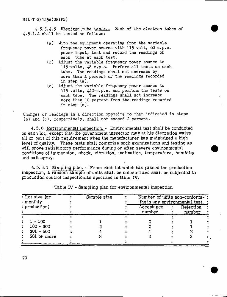
MIL-T-23125A(SHIPS)
4.5.5.4.5 Electron tube tests.- ~ch Of the electron tubes Of4.5.1.4 shall be tested as follows:
●
(a)
(b)
(c)
With the equipment operating from the variable.frequency power source with 11 5-volt, 60-c .p. s.power input, test and record the readings ofeach tube at each test.Adjust the variable frequency power source to115 -volts,@-c. p.s. Perform all tests on eachtube. The readings shall not decrease by.more than 4 percent of the readings recordedin step (a).
Adjust the variable frequency power source to115 volts, 440-c .P. s. and perform the tests onsach tube. Ths readines shall not increasemore tinan”10 percent f~om the readings recordedin step (a).
Chan~es of readings in a direction opposite to that indicated in steps(b) ~nd (c), resp~ctively, shall not-exceed 2 percent.
4.5.6 Environmental inspection.- Environmental testshallbe conductedon each lot,exceptthatthe government inspectormay at hk discretionwaiveallor partof thisrequirement when themanufacturer has maintaineda tdghlevelofquality.These testsshallcomprise such examimtions and testing aswill prove satisfactory performance during or after severe environmentalconditions of immersion, shock, vibration, inclination, temperature, humidity
●and salt spray.
I 4. 5.6.1 Sampling plan. - From each lot wtich has passed the productioninspection. a random sam~le of units shsll be selected and shall be subjected toproductio~ control inspect~on.as specified in table IV.
I Table IV - Sampling plan for environmental inspection
: Lot size (or Sample size : Number of units non-conform- :: month~y fng in any environmental test. :: production) Acceptance : Rejection :
: number ,number :: : :
1-100 1 0 1 :.100-300 2 0 1:
: 301-500 : 4 : 1 : 2 :501 o? more 8 : 2 : 3 :.
: .:
70
●
MIL-T-23125A(SHIPS)
4.5.6..1.1Rejection. - Each of the units selected in accordance with thesampling plan shall be subjected to the environmenhl tests. The resuIts ofeach test shall be compared with the requirements of this specification. Anydeviations from this specification for any such tests shall be counted as a defectand the unit shallbe rejected. Rejected lots may be offered again forinspection provided the cause of defect has been determined and corrected in allunits of the lot and the contractor has tested a random sample of reworked unitsto determine their compliance.
4. 5.6.2 Test equipment. - Test equipment for environmental testing shallbe selected in accordance with the requirements of this specification and ofMIL-E-16400.
4. 5.6.3 Specific environmental tests. - In addition to the satisfactoryopera tion tests specified hereinafter, the inspector may require performance ofany of the tests of 4.5.3, 4. 5.4 or 4. 5.5 as part of the temperature, humidity,shock, vibration and life tests described herein.
4.5.6.3.1 Satisfactory operation tests. - The check for satisfactory operationduring the course of environmental tests shall consist of the repetition of the testsspecified hereinafter when the equipment is operated in a controlled environmentchamber, input power connections shall be through sealed feed through connectionsin the chamber and the equipment shall be energized. The calibration controls
● located in the auxiliary compartment shall not be adjusted unless specified.
4. 5.6.3.1.1 Calibration tests. - The test of table V shall be performedprior to 4.5.6.3. 2(d). Any necessary calibrations shall be made by the contractor.Thereafter, the tests shall be performed without further adjustment except foradjustments with cards, through 10, not to exceed once every four cycles.
71
I ●
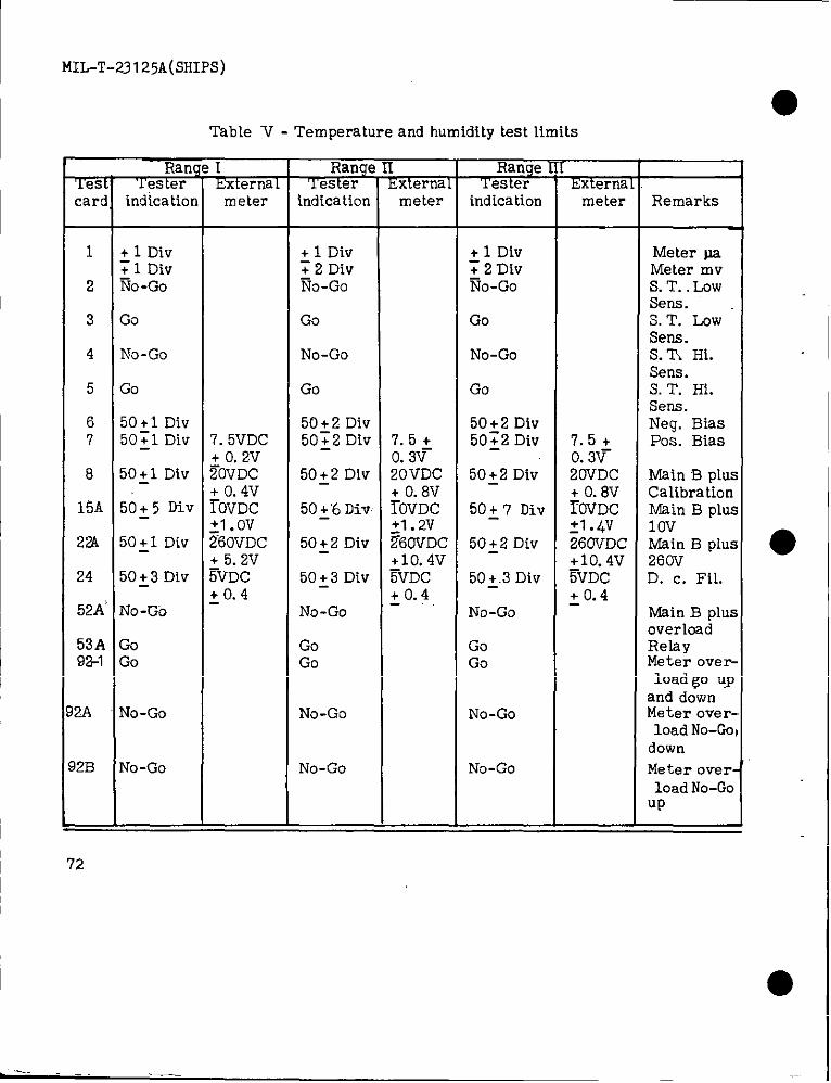
MIL-T-23125A(SHIPS)
mcar(
—
1
2
3
4
5
67
8
15A
22A
24
52A
53A92-1
2A
12B
=
RamLester
indication
~ 1 Div~ 1 DivNo-Go
Go
No-Go
Go
50+ 1 Div50~l DIV
50~1 Div
50~ 5 Div
50~1 Div
5033 Div
No-Go
GoGo
No-Go
No-Gc)
Table V - Temperature and humidity test limits
IIxternalmeter
7.5VDC+ o.2V~OVDC+ o. 4VrOVDC:1. OvZ60vDc+ 5. 2V%DC+0.4
T&Yindication
+ 1 Div~ 2 DivNo-Go
Go
No-Go
Go
50~2 Div50~2 Div
50:2 Div
50~’6Div
50+ 2 Div
50~3 Div
No -Go
GoGo
No-Go
No-Go
Lm-6Fii5
meter
7.5+o. 3v-20VDC+ O.8V~OVDC:1. 2VZ60VDC+10. 4V~VDC+0.4
--’&%-indication
+ 1 Div~ 2 DlvNo-Go
Go
No-Go
Go
50+2 Div50~2 Div
50~2 Div
50~ 7 Div
50~2 Div
50~.3Div
No-Go
GoGo
No-Go
No-Go
EEFimmeter
7.5+o. 3v-20VDC+ O.8V~OVDC31 .~v260VDC+10. 4V%DC+0.4
Remarks
Meter paMeter m vS.T. LOWSens.3.T. LOWSens.s. m H1.Sena.S. T. Hi.Sens.Neg. BiasPos. Bias
Main B pluCalibrationMain B plu1OvMain B plu;260vD. c. Fil.
Main B plwoverloadRelayMeter overloadgo UIand downMeter overloadNo-Gcdown
Meter over
loadNo-CCUP
●
72
●I
.—.
●
4.5.6.3.
(a)b)(c)
(d)
(e)
(f)
(9)
.2
MIL-T-23 125A(SRIPS)
Calibration ceH tests. -
Install calibration cell in actual test socket.Insert test card number 1 in the programming switch.Actuate test button number and record the panel meter reading.
The reading obtained shall meet the limits specified in table V.Actuate test buttons number “2and number 4 and record the panel
meter reading. The reading obtained shal~ meet the limitsspecified in table V.
Remove test card number 1 and install test card number 2. Theshort indicator shall indicate no shorts.
Remove test card number 2 and ins~l’1 test card number 3. Cathodeto control grid short indication shall occur.
Remove test card number 3 and install test card number 4. Actuatethe sensitive grid shorts switch in the auxiliary compartment. Noshort indicators shall light.
Remove test card number 4 and install test card number 5. Actuatethe sensitive grid shorts switch in the auxiliary compartment.Control grid to suppressor grid short indicator shall light.
(i) Remove test card number 5 and the calibration cell.4.5. 6.3.1.3 Voltage tests. - All voltage measurements shallbe made by
●actuatingtestbuttonnumber 2 and recordingthepanelmeter reading.
(a) Inslalltestcard number 6, actuatetestbuttonnumber 2. The readingobtainedshall be recorded and shall meet the limits specified intable V.
(’b) Remove test card number 6 and install test card number 7.(c) Connect the d. c. vo~tmeter from pin number 3 to pin number 6 of
the octal socket with the positive meter lead to pin number 3. Themeter reading observed shall be disregarded.
(d) Actuate test button number 2, the @nel meter and the d. c. voltmeter Ireadings obtained shall be recorded and stall meet the limitsspecified in table V.
(e) Remove test card number 7 and install test card number 8.(f) With the voltmeter connected as in step (c) actuate test button number
2, the panel meter and the d. c. voltmeter readings obtaifled shallbe recorded and shall meet the limits specified in table V.
(9) Remove test card number 8 and install test card number 15A.
73
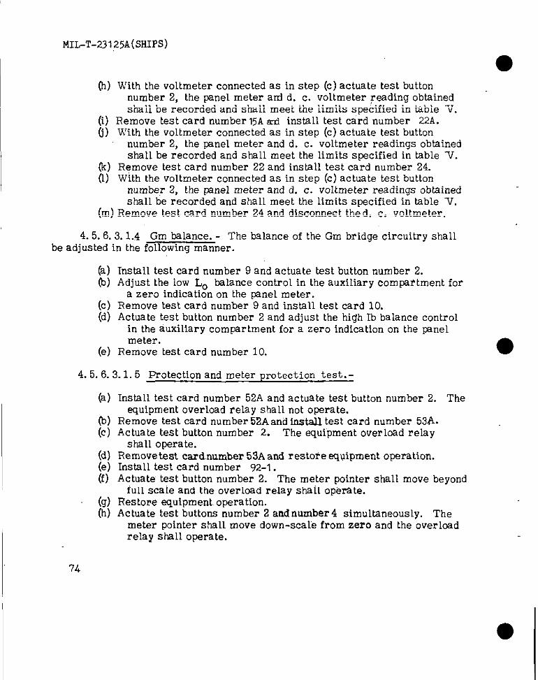
MIL-T-23125A(SHIPS)
(h) With the voltmeter connected as in step (c) actuate test buttonnumber 2, the panel meter ad d. c. voltmeter reading obtainedshall be recorded and shall meet the limits specified in table V.
(i) Remove test card number 15Ad install test card number 22A.(j) With the voltmeter connected as in step (c) actuate test button
number 2, the pane~ meter and d. c. voltmeter readings obtainedshal~ be recorded and shall meet the limits specified in table W.
(k) Remove test card number 22 and install test card number 24.(1) With the voltmeter connected as in step (c) actuate test button
number 2, the panel meter and d. c. voltmeter readings obtainedshall be recorded and shall meet the limits specified in table V.
(m) Remove test card number 24 and disconnect the d. c. voltmeter.
4.5.6 .3.1.4 Gm balance. - The balance of the Gm bridge circuitry shallbe adjusted in the following manner.
(a)b)
(c)(d)
(e)
Install test card number 9 and actuate test button number 2.Adjust the low Lo balance control in the auxiliary compartment for
a zero indication on the panel meter.Remove test card number 9 and install test card 10.Actuate test button number 2 and adjust the high Ib balance control
in the auxiliary compartment for a zero indication on the panelmeter.
Remove test card number 10.
4. 5.6.3.1.5 Protection and meter protection test. -
(a)
(-b)(c)
(d)(e)(f)
(9)(h)
Install test card number 52A and actuate test button number 2. Theequipment overload relay shall not operate.
Remove test card number 52A and install test card number 53A.Actuate teat button number 2. The equipment overload relay
shall operate.Remove test card,number 53A and restore .eqUipment operation.InstaH test card number 92-1.Actuate test button number 2. The meter pointer shalI move beyond
full scale and the over~oad relay shal~ oper’ate.Restore equipment operation.Actuate test buttons number 2 and number 4 simultaneously. The
meter pointer sha H move down-sca[e from zero and the overloadrelay shall operate.
●
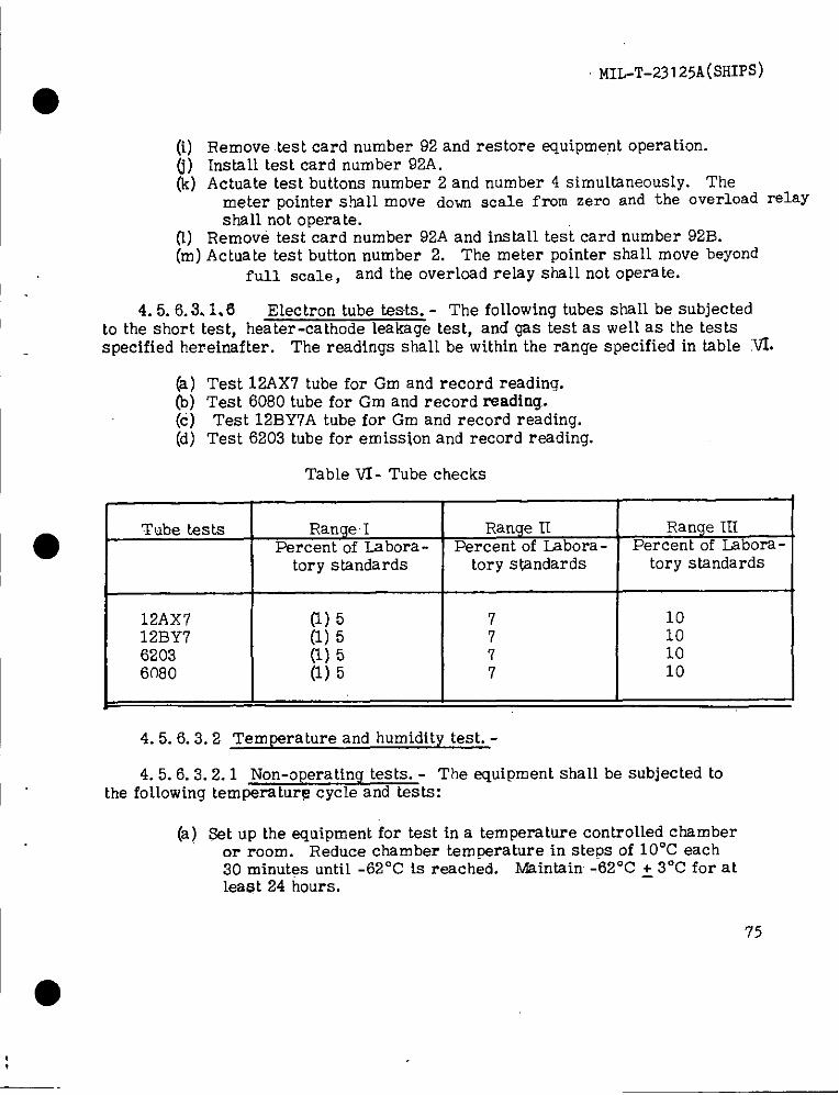
MIL-T-23125A(SHIPS)
(i) Remove test card number 92 and restore equipment oPeration.(I) Install test card number 92A.(k) Actuate test buttons number 2 and number 4 simuNaneously. The
meter pointer shall move dow scale from zero and the overload relayshall not operate.
(1) Remove test card number 92A and install test card number 92B.(m) Actuate test button number 2. The meter pointer shall move beyond
full scale, and the overkad relay shs~~ not operate.
4.5.6.3.1.6 Electron tube tests. - The following tubes shall be subjectedto the short test, heater-cathode leakage test, and gas test as well as the testsspecified hereimf ter. The readings shall be within the range specified in table ~.
(a)(b)(c)(d)
I
Test 12AX7 tube for Gm and record reading.Test 6080 tube for Gm and record reading.Test 12BY7A tube for Gm and record reading.
Test 6203 tube for emission and record reading.
Table VI- Tube checks
, 1 +
●Tube tests Range I Range H Range HI
Percent of Labora - Percent of Lsbora- Percent of Labora-tory standards tory standards tory standards
12AX7 (1) 5 7 1012BY7 (1) 5 7 106203 (1) 5 7 106080 (1) 5 7 10
4. 5.6.3.2 Temperature and humidity test. -
4. 5.6.3.2.1 Non-operating tests. - The equipment shall be subjected tothe following temperature cycle and tests:
(a) Set up the equipment for test in a temperature control~ed chamberor room. Reduce chamber temperature in steps of 10”C each30 minutes until -62°C is reached. Maintain -62°C ~ 3°C for atleast 24 hours.
75
I ●
—.
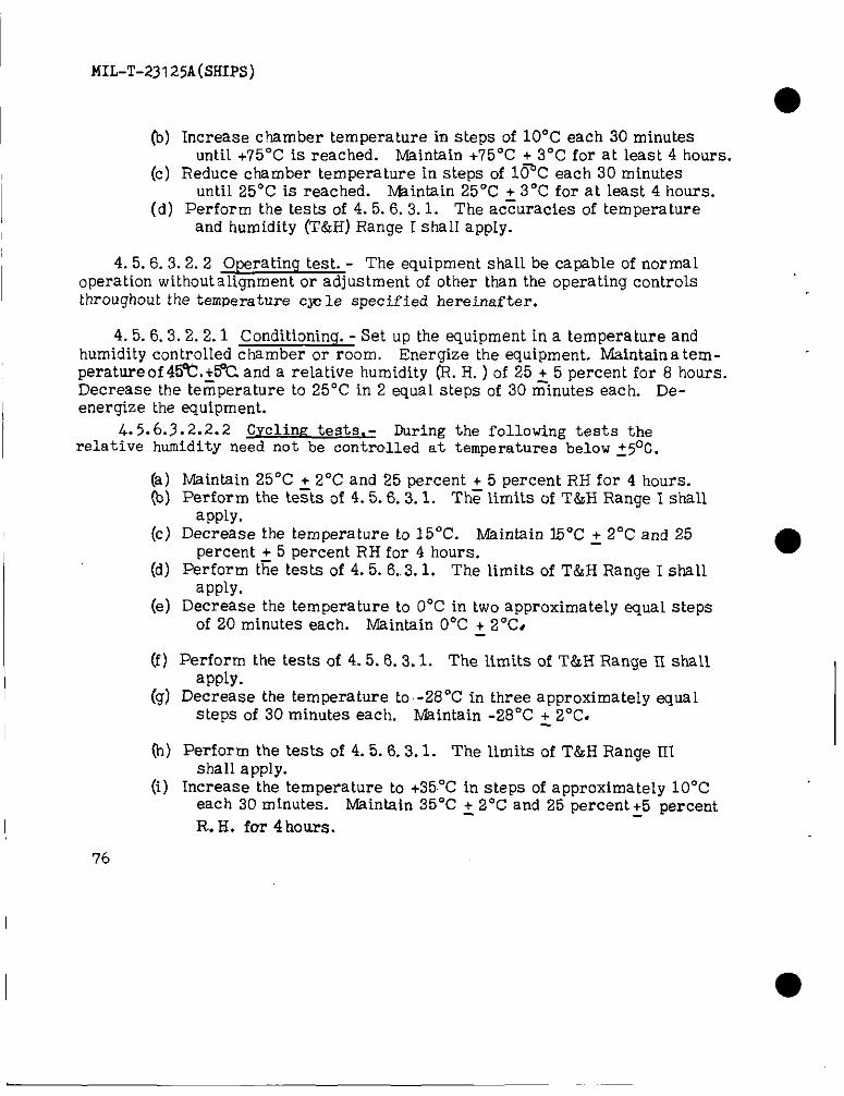
MIL-T-23125A(SHIPS)
●(b) Increase chamber temperature in steps of 10”C each 30 minutes
until +75°C is reached. Maintain +75°C + 3°C for at least 4 hours,(c) Reduce chsmber temperature in steps of l@C each 30 minutes
until 25°C is reached. Mainain 25°C ~ 3 “C for at least 4 hours.(d) Perform the tests of 4.5.6.3.1. The accuracies of temperature
and humidity (T&H) Range I shall apply.
4. 5.6.3.2.2 OWrating test. - The equipment shall be capable of normaloperation without alignment or adjustment of other than the operating controLsthroughout the temperature cw le specified hereinafter.
4. 5.6.3.2.2.1 Conditioning .- Set up the equipment in a temperature andhumidity controlled chamber or room. Energize the equipment. Maintain a tem-perature of 4~.+&C and a relative humiditv (R. H. ) of 25 + 5 Dercent for 8 hours.
IDecrease the te~perature to 25°C in 2 equ~l “steps’of 30 =ln~tes each. Re-energize the equipment.
4.5.6 .3.2.2.2 Cyclirw tests. - During the following tests therelative humidity need not be controlled at temperatures below ~5°C.
(a)(b)
(c)
(d)
(e)
(f)
(9)
h)
(i)
Maintain 25°C + 2°C and 25 percent + 5 percent RH for 4 hours.Perform the te~ts of 4.5.6.3.1. Th~ limits of T&H Range I shall
app~y.Decrease the temperature to 15”C. Msintain 15°C + 2°C and 25
percent ~ 5 percent RH for 4 hours. ●Perform the tests of 4.5.6..3.1, The limits of T&H Range I shall
apply.Decrease the temperature to O“C in two approximately equal steps
of 20 minutes each. Maintain O“C + 2“C,
Perform the tests of 4.5.6.3.1. The limits of T&H Range II shallapply.
Decrease the temperature to .-28°C in three approximately equal.StePSof 30 minutes each. Maintain .28°C + 2“C.
Perform the tests of 4.5.6.3.1. The limits of T&H Ranae IIIshall apply.
Increaae the temperature to +35°C in steps of approximately 10”Ceach 30 minutes. Maintain 35°C ~ 2°C and 25 percent~5 percent
R.. H. for 4hours,I
76
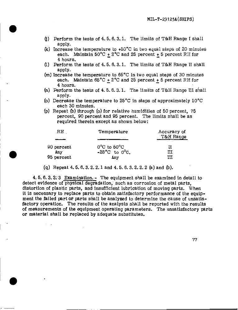
f.flL-T-23125A(sH1ps)
6) %a$~;m the tests of 4.5.6.3..1. The limits of T&H Range I shall
(Ii) Increas~ the temperature to+50”C in two equalstepsof 20 minuteseach. Maintain50”C ~ 2°C and 25 percent ~ 5 percent RH for4 hours.
(1) Perform the tests of 4.5.6.3.1. The limits of T&H Range II shallapply.
(m) Increase the temperature to 65°C in two equal steps of 30 minuteseach. Maintain 65°C ~ 2°C and 25 percent ~ 5 percent RH for4 hours.
I (n)
I (P)
Perform the tests of 4.5.6.3.1. The limits of T&H Range III s~allapply.
Decrease the temperature to 25°C in steps of approximately 10”Ceach 30 minutes.
Repeat (b) through (o) for relative humidities of 50 percent, 75percent, 90 percent and 95 percent. The limits shsH be asrequired. therein except as shown below:
RH Tern pers ture Accuracy ofT&H Range
90 percent O“c to50”CAny -28°C to O°C.
95 percent Any
IImm
(q) Repeat 4.5.6.3.2.2.1 and 4.5.6.3.2.2.2 (a) and (b).
4.5.6.3.2:3 Exsmimtion. - The equipment shall be examined in detail todetect evidence of physical degradation,’ such as corrosion of metal parts,distortion of plastic parts, and insufficient lubrication of moving parts. Ik:henit is necessary to replace parts to obtain satisfactory performance of the equip-ment the failed prt or parts shsIl be analyzed to determine the cause of unsatis-factory operation. The results of the analysis shall be reported with the resultsof measurements of the equipment operating prameters. The unsatisfactory prtsor material shall be replaced by adequate substitutes.
77
I ●
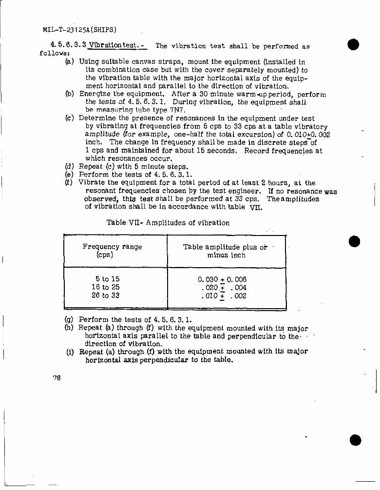
1 MIL-T-231 25A(sHIPs)
4.5.6.3.3 Vibration test. - The vibration test shall be perfomned asfOllows:
(a) Using siitablecanvas straps,mount theequipment (installedinitscombinationcase but with thecover separatelymounted) tothevibrationtablewith themajor horizontalaxisof theequip-ment horizontaland paralleltothedirectionofvibration.
(b) Energize theequipment. Aftera 30 minute warm-up period,performthetestsof4.5.6.3.1. During vibration,theequipment shallbe measuring tubetype7N7.
(c)Determine thepresence ofresonances in theequipment “undertestby vibratingatfrequenciesfrom 5 CPS to33 cps ata tablevibratoryamplitude (forexample, one-halfthetotalexcursion)ofO.010~0.002inch. The change infrequencyshallbe made in’discretestepsof1 cps and maintainedforabout 15 seconds. Record frequenciesatwhich resonances occur.
(d) Repeat (c) with 5 minute steps.
i
(e) Perform the tests of 4.5.6.3.1.(f) Vibrate the equipment for a totsl period of at least 2 hours, at the
resonant frequencies chosen by the test engineer. If no resonance wasobserved, th@ test shall be performed at 33 CPS. The amplitudesof vibration shall be in accordance with table ~.
Table VII- Amplitudes of vibration
&
Frsquency range Table amplitude plUS O* ●(Cps) minus inch
5 to 15 0.030 + O.00616 to 25 020,; .00426 to 33 :010: .002
(9) Perform the tests of 4.5.6.3.1.(h) Repeat (a) through (f) with the equipment mounted with iffi major
horizontal axis parallel to the tsble and perpendicular to the. ‘“direction of vibration.
(i) Repeat (a) through (f) with the equipment mounted with its majorhorizontal axis perpendicular to the table.
I
78
MIL-A-23125A(SHIPS)
(j) Acceptability will be contingent upon the ability of the equipmentto withstand tests specified above and the ability to perform its,principal functions during and after vibration tests. Minor damageor distortion will be permitted during test providLng such damageor distortion does not Lnany way impair the abil Ity of the equipmentto perform its principal functions. Nonrepetitive failures of suchparts as vacuum tubes, condensers, and wiring, which can beeasi~y replaced or repatred are generally considered mfnor failures.If minor failures occur the test shaH be stopped, the repatr made,and the entke test in that plane repeated. If major faihres occur,the test shall be discontinued and, after repairj the entire test shall‘be repeated, un~ess otherwise spectfied by the bureau or agencyconcerned. The manufacturer may, at hLs option, substitute anentirely new equipment for retest. If this option Ls taken, it shaILbe noted h the test report furnished as specified in 4.5.6.3.3.1.
4. 5.6.3.3.1 Test report. - The test report to be furnished the bureau oragency concerned by the testing Laboratory shall Lnclude detailed descriptionsof any damage or maLftmctioning incurred and at what stage in the tests itoccurred. Photoqaphs of physicaL damage .shal~ be included. Recommendationsare desired as to what corrective measure, ff any, should be taken. At thediscretion of the test engineer, it shall also fnclude other pertinent Information,such as the over aLl dimensions of the equipment, its weight, approximate Location
● of the center of gravity, and a sketch or photograph of tb~ methods used in mount-tng M on the test machines.
4. 5.6.3.4 Shock test. - Except as specified herein, each equipment shaH besubjected to the shock tests specified fn MIL-S-901. The following conditionsshall apply:
(a) The equipment shaLl be mounted with suitable canvas straps. Thecover shall be removed from the case and separately mounted tothe shock table.
(b) The tests of 4.5.6 .’3.1 shalL be performed before any blows andafter the 3 blows of each plane.
(c)3#ng the bLows, the equipment shaIL be measuring tubetype
(d) Th~ee blows shall be applied parallel to each of the threeprintipal exes of the apparatus being tested. The three blowein each horizontal direction shall be with heights of h~erdrop of 1 foot, 2 feet, and 3 feet, respectively,and thethree blows in the vertical direction shall be with heightsof 2 feet, 3 feet, and 4 feet, respectively.
4. 5.6.3.5 Accelerated life tests .-t.he following conditioning and test,s:
The equipment shall be sub j ect,ed to
79
MIL-T-23125A(SSIPS)
●4.5.6.3. S. 1 Conditioning. -
4. 5.6.3.5.1.1 Normal operation. - The equipment shall first be set up ina chamber in an ambient temperature of 25” ~ 5“C. with a relative humidity of50A 3 percent, and operated under nomihal conditions of line voltage andfrequency in accordance with 3.5.1. Foilowing warn-up, the test of 4.5.6.3.1shall be performed. The results shall be recorded as reference data.
4.5.6.3 .5.1.2 High temperature operation. - Chamber tern perature shal~ beincreased to 65” PLUSor ❑ inus 5“C. and not less than 90 percent relativehumidity. The eiuiprn ent shall be operated under nom inai supply voltage andfrequency, for a period of 2 hours. During the last 30 minutes the test of4. 5.6.3.1 shall be performed.
4. 5.6.3.5.2 Test cycUng. - Immediately follow!ng the high-temperatureconditioning the equipment shah be subjected to the following series of cycLeswhile operating in an ambient tern perature of 65” ~ 5“C. snd a relative humidityof not less than 90 percent.
(a) Increase &Iput voltage to 126.5 volts end operate in this con-dition for 1 hour and 15 minutes.
(b) Decrease ihput voltage to 103.5 volts and operate in this con-dition for 1 hour.
(c) Increase input voltage to l15volts,operate the equipment for 30m hmtes in this condition and then remove power for 15 minutes.During the iast 30 mfnutes of operation, repeat 4.5.6.3.1.
(d) At the end of the 15-m tnute shut-down period energize theequipment with 103.5 volts and operate in this condition for1 hour.
(e) Increase input voltages to 126.5 voks and operate in this con-dition for 1 hour and 15 minutes.
(f) Decrease input voitage to nominal and operate for 30 m iputesrepeating 4.5.6.3. L At the end of the 30 minhte period shutdown the equipment for 15 m fnutes.
(g) z~:~oa~$) through (f) without interruption for a period of
4. 5.6.3.5.3 Procedure in case of shut-down. - Shouid a single shut-downfor more than 1 hour or a total down time of 5 hours during the 200 hours ofcontinuous operation be ~eqessary, the continuation of the ~est shall be for200 hours from the time of resumption of the run.
80
MIL-T-23125A(SHIPS)
4.5. 6.3.5.4 Temperature measurement. - Temperature measurfng instrumentsshall be placed at critical points throughout t~e equipment, covering suspectedhot spots. Data shall be recorded at least once durtng each cycle, at the end ofthe period of high voltage operation.
4.5.6.3.6 Drip-p roof (enclosure) test for combination case. -
(a) Repeat 4.5.6.3.1.(b) Mount the equipment de-energized in its combination case with
cover installed in such fashion as to permit tMng of its verticalaxis h any direction to the extent of 75 degrees to the hor izont.zd.The equipment so mounted shaU be placed on the tilt tabledirectly below a hose with a 1-inch untform diameter nozzleinstaUed not less than 3 feet above the top of the equipment. Thenozzle shall be fitted with a domestic type sprinkling faucet.
(c) The enclosure of the equipment shall be tested by subjecting itto a.stream of water under a velocity head at the nozzle of 1 foot.The nozzle shall be directed downward to the test position.
(d) Durtng the test the unit shall be tilted in all directions andsubjected to the test in accordance with the following schedule:
(1) Stream dtrected unto top(with table horizontal) for 15minutes.
(2) Stream dtrected for 5 minutes onto each completelyclosed side containing controls, .p@els, cable entrances,louvers and. so forth (tflt. the table so thaithe side beingsprayed is 75 degrees from the horizontal ).
(e) Return the equipment to the horizontal (tilt table horizontal)and repeat 4.5.6.3.1. Remove the instrument from its combinationcase. Any leakage accumulated in pockets tn the bottom or in anyother part of the enclosure will constitute failure of this test.
4. 5.6.3.7 Post environmental tests. - The. specific operating tests of 4.5.3.2sha~l be repeated after all of the environmental tests of 4. 5.6.3.2 through 4. 5.6.3.6being performed on a given unit have been performed. Any unit failing to conformto the requirements of 4. 5.3.2 shall be counted as failtng to pass to the environmentaltest!and shall be rejected.
81
I ●
L-

MILTT-23125A(SHI.PS)
,, L.5.6..3.8 1+.uxzi test. - If required by the inspector parts of theequipment not completely in acco rdanie with MII,-E-I 6400 shall be testedin ac :ordaice with MIL-T-945 to assure compliance with 3.8.1.2.
L. 5.6.3.9 Salt sm-av test .- Parts of the equipment not in accordancewith MIL-E-16400 shall be subjected to a 100-hour saltspray.teSt in
accordance with FEO-STL!-151 as specified in MIL-E-I64oo.
4.5.6.3.10 Radio interference and ,undesired radiation t,est~, _fidio interference and undesired radiation tests for portable equipmentshall be conducted in accordance with MIL-I-1 6910.
4.5.6.3.11 weld test .- When required by the inspector, samplepieces representative of production, and welded on the machines usedtherefor, shall be tested to destruction to determine conformance withMIL-E-I 6400.
5. PFXPARATIONFOR DELIVERY
5.1 Domestic shiument and earl+ equipment installation and st,oraaeof onboard reuair parts. -
5.1.1 Test set, AN/USM-118( ).-
5.1.1.1 Preservation and packa~in~. - Preservation and packaging shallbe sufficient to afford adequate protection against corrosion, deterioration ●and physical damage during shipment from the supply source to the usingactivity and until early installation and may conform to the supplier!scommercial prsct.ice when such meets these requirements.
5.1.1.2 Packing.- Packing shall be accomplished in a m&mer whichwill insure acceptance by common carrier at the 10west rate and willafford protection agairmt physical or mechanical damag’eduring directghipment from the supply source to the using activity for early installationThe shipping containers or method of packing shall conform to the UniformFreight Classification Rules and Regulationsor other carrier regulationsas applicable to.the mode of transportationand may conform to theSupplierts commercial practice when such meets these requirements.
5.1.1.3 Marking.- Shipment marking information shall be provided ,on interior packages and exterior shipping containers in accordancewith the contractor!s commercial practice. ‘Theinformation shall includenomenclature,Federal stock number or manufacturer!s part number, contractor order number, contractor!s name and destination..
5.1.2 Onboard reuair uarts. - Onbomd repair parts shall be preservedand packaged level A; packed level C and marked in accordance with MIL-E-17555.
82
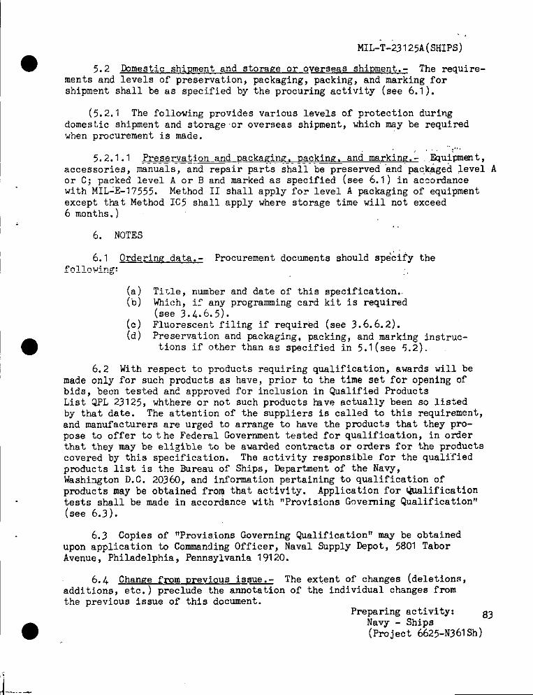
MIL-k-23125A(sHIps)
5.2 Domestic shipment and storwe or overseas shiDment. - The require-ments and levels of preservation, packaging, packing, and marking forshipment shall be as specified by the procuring activity (see 6.1 ).
(5. 2.1 The fOll@ing provides various levels of protection duringdomesLic shipment and storageor overseas shipment, which may be requiredwhen procurement is made.
..,.,5.2.1.1 preservation and Dackaginv, uackine. and markine.- ,jZqu+pment,
accessories, manuals, and repair parts shall be preserved ‘andpackaged levelor C; packed level A or B and marked as specified (see 6.1) in accordancewith MIL-E-17555. Method II shall apply for level A packaging of equipmentexcept that Method IC5 shall apply where storage time will not exceed6 months.)
.,6. NOTES
6.1 ~rin~ data.- Procurement documents should specify thefollowing: ,,
(a) Title, number and date of this specification..(0) mi,~h, if any programming card kit is required
(see 3.4.6.5).(c) Fluorescent filing if required (see 3.6.6.2).(d) Preservation and packaging, packing, and marking instruc-
tions if other than as specified in 5.1(see 5.2).
6.2 With respect to products requiring qualification,awards will bemade only for such products as have, prior to the time set for opening ofbids, bec?ntested ant?approved for inclusion in Qualified ProdmtsList QPL 23125, whthere or not such products have actually been so listedhy that date. The attention of the suppliers is called to this requirement,and uanufacturers are urged to arrange to have the products that they pro-pose to offer to t he Federal Government tested for qualification, in orderthat they may be eligible to be awarded contracts or orders for the productscovered by this specification. The activity responsible for the qualifiedproducts list is the Bureau of Ships, Departmentof the Navy,Washington D.C. 20360, and informationpertaining to qualification ofproducts may be obtained from that activity. Application for Qualificationtests shall be made in accordance with “ProvisionsGoverning Qualification”(see 6.3).
6.3 Copies of “Provisions Governing Qualification” may be obtainedupon application to Commanding Officer, Naval Supply Depot, 5801 TaborAvenue, Philadelphia, Pennsylvania 19120.
6.4 Chan#e from m-evious iss= The extent of changes (deletions,additions, etc. ) preclude the annotation of the individual changea fromthe previous issue of thig document.
A
Preparing activity:Navv - ShiDs
83
(P~ject ~625-N361Sh)
J----
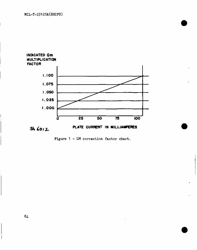
MIL-T-23125A(SHIPS)
a
INDICATEDGmI MULTIPLICATIONI FACTOR
I 1.100
I .075
I .050
1.025
1.000
Sk601L
1 Jo 25 50 75 100
PLATE CURRENT IN MILLIAMPERES
Figure 1 - GM correction factor chart.
I
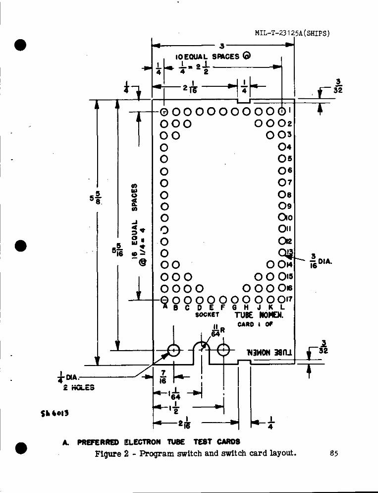
-m
MIL-T-231 ;5A(SHIPS)
i y’+-pit
TT’‘Qooooooooool000 000200 0030 040 050 06
—
+“ -m2NOLES
0000
:0000000000
07
08
0900011
o;
00 ol~oooo~
-www%m??’7SOCKET TlmE Nom.
- :OIA.
A. PREFER~ ELECTRON lUSE TEST CMOSFigure 2- Program switch and switch card layout. 85
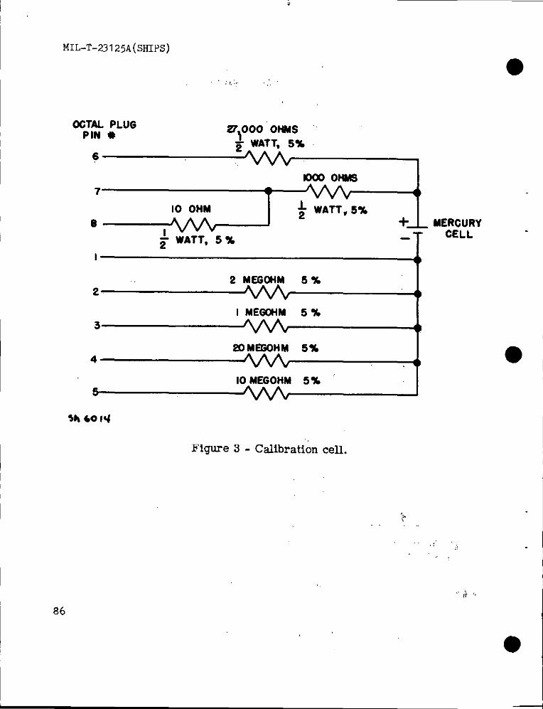
MIL-T-231 25A (SHIPS)
,’ ;r..:. “.
OOTALPLUGPIN #
61
1000ONMS7
10 OHM + WATT, 5%e MERCURY
CELL
2 MEGONM 5 %2
I MEGOHM 5 %3
20MEGOHM5%4
10 MEGOHM 5%I
$h 6014
Figure 3- Calibration cell.
I %6
●
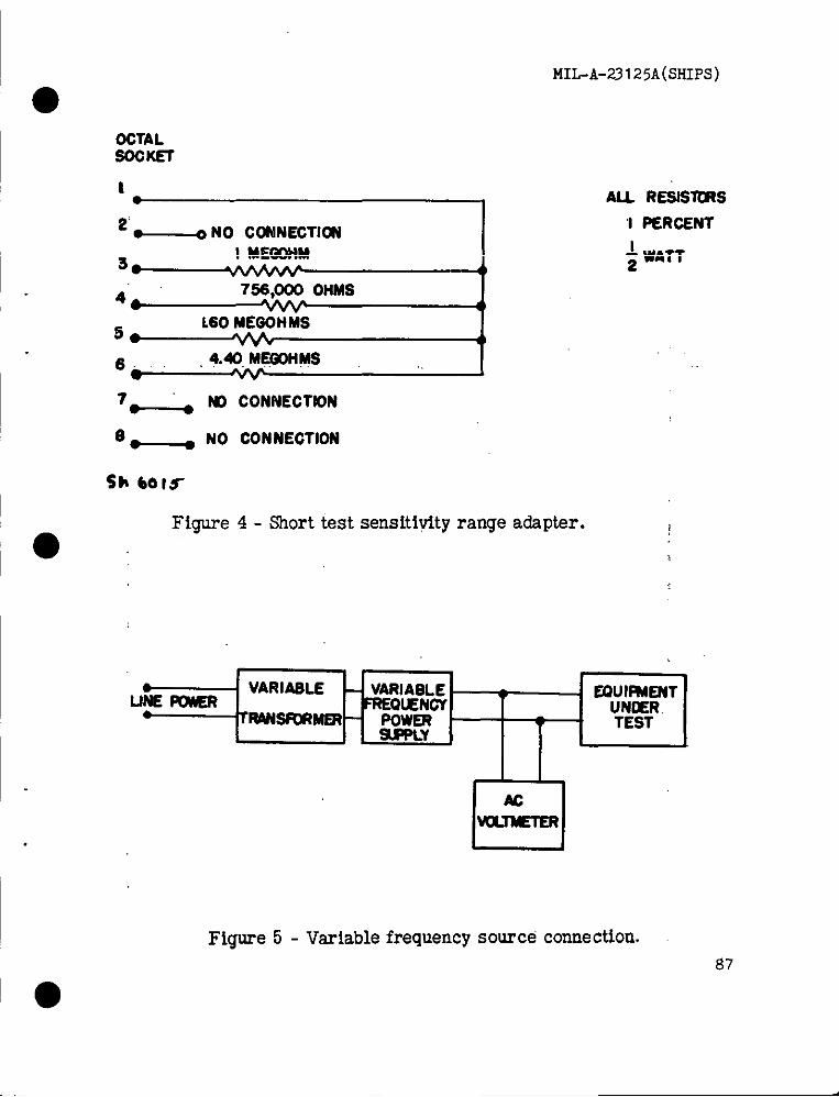
MIL-A-23125A(SHIPS)
●OCTALSOCKE7
1 AL RESIS~S
2 ~ NO CONNECTI~I PERCENT
3*I MEGOHM ~ WATT
dI
46 76S,000 OHMS( I
5*160 MEGOHMS
*6. 4.40 MQ3014W ,. !7- M CONNECTION
em ● NO CONNECTION
Sh 601S
Fi~e 4- Short test sensiti~t y range adapter.
0
I● VARIABLE - VARIABLE
LINEm FREQIENCY. EIWIUIIJT
Transformer – POWERL -Y
TEST
M
Figure 5- Variable frequency source connection.
87
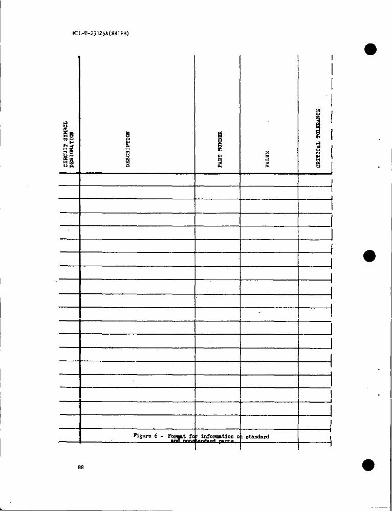
KIL-’P-231”25A(SHIPS)
.
—
—
—
.
—
—
—
—
—
—
—
.
—
.
.
—
—infomtion standard
I
1
I
1
I1
I
I
ea
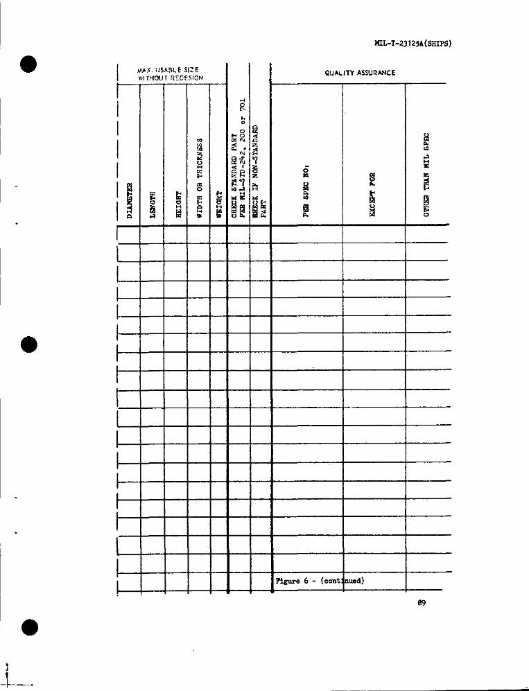
MIL-T-23125A(SKIPS)
1’y
I
I,!!f1-L_1-1-l–1-t-l–
El--1-1----Ft-E1-l--
—
—
—
—
—
—
—
—
—
—
—
—
—
—
—
—
—
—
—
—
—
—
—
—
—
—
—
—
—
—
—
—
—
—
—
—
—
—
—
—
—
—
—
—
—
—
—
—
—
—
E.&
—
—
—
—
—
—
—
—
—
—
—
—
—
—
—
—
—
—
—
QuALITYASSURANCE
I
I
=FI
II
‘iEur06- (cent ued)
89
I
●
- k-—---
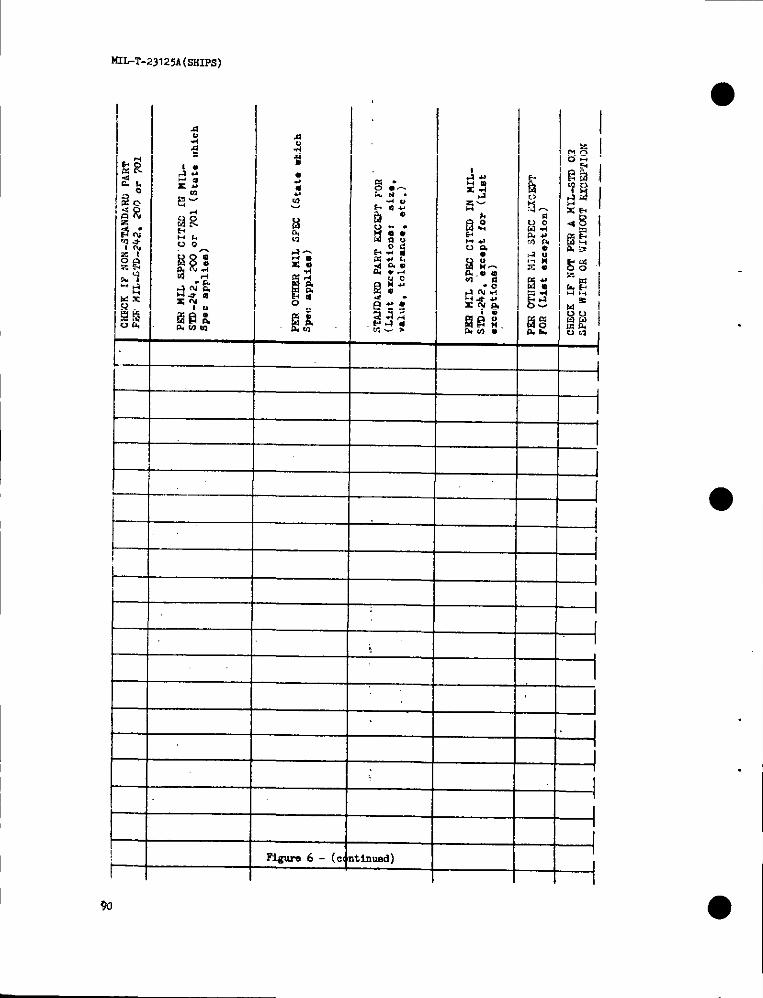
MIkT.23125A(L+IIps)
%
FiguIw6- (c, Inund)
—
—
—
—
--l11I-1-_.../-4--.-1--1--l1i--l-4–1--l---1-i
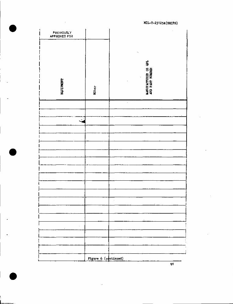
● ❉ pREVIOJSCf
iAPPRovEDFOR
I
I 4I
I
I
L.._.____...
I
I
I
t41L4.23125A(stiIps)
I
?igure 6 (c ntinued)
91
L.

~~T-231zsA(sHIPs)
.—..—
-..——
.
.——
92
—
—
—
—
.—
—
—
—
—
—
—
—
—
.
—
—
—
—
—
—
—
—
—
—
—
—
.
—
—
—
.
—-
—
—
—
—
.
—
—
; (c.
I
I
II
I
i
——.- ———————4
I---+I
I
timed) I
II
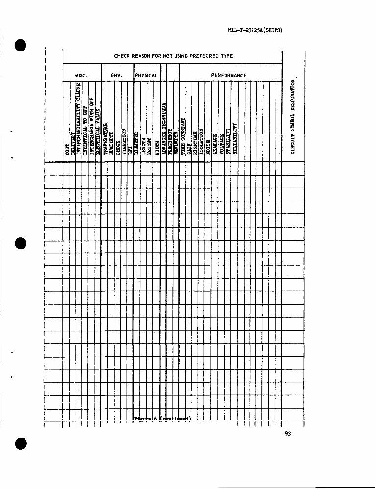
I I!WT-23125A[SEIIPS)
@i
ICUECKREASONFORNOTUSINGPREFERREDNPE
I MISC. I ENv. PHYSICAL I PE!?FORUANCE
1-
93
●

MIL-T-23 I 25A(SHIPS)
I 9/!$
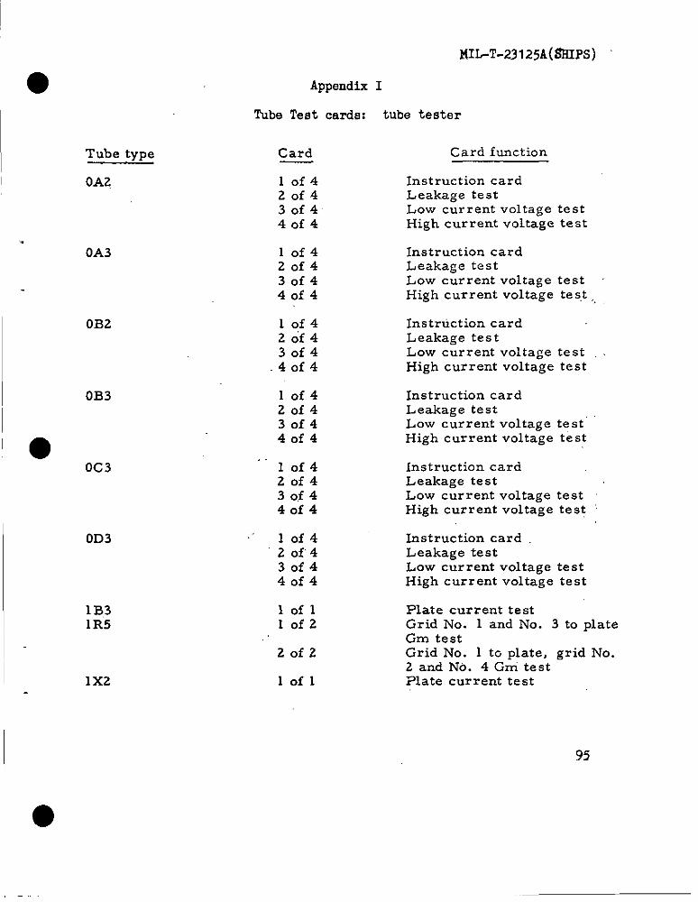
●
Tube type
OA2
OA3
0B2
0B3
Oc 3
0D3
1B31R5
1x2
Appendix I
Tube Test cards: tube
Card
10f420f430f440f4
lof420f430f44of4
10f42of43of44of4
10f42of430f44of4
10f420f43of44of4
lof42of43of440f4
loflIofz
20f2
lofl
MIL-T-23125A(tiIiIPS)
tester
Card function
InstructioncardLeakage testLow current voltage testHigh current voltage test
Instruction cardLeakage testLow current voltage testHigh current voltage teS.t ,,
Instruction cardLeakage testLow current voltage test
High current voltage test
Instruction cardLeakage testLow current voltage test’High current voltage test
Instruction cardLeakage testLow current voltage testHigh current voltage test ‘
Instruction cardLeakage testLow current voltage testHigh current voltage test
Plate current testGrid No. 1 and No. 3 to plateGm testGrid No. 1 to plate, grid No.2 and No. 4 Gni testPlate current test
95
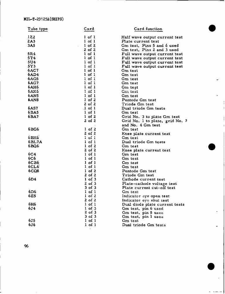
I
MIL-T-23125A@HIPS)
I
I
Tube type
lZ.22A33A5
5R45T45U45Y36AC76AD46AG56AG76AH66AK66AN5&4N8
6AS76BA56BA7
6BG6
6BI-16’6BL7A6BQ6
6G46C66cB6.y=:;”
6D4
6D66E5
61-266J4
6J56J6
Card
Iofllofl10f220f2loflloflloflloflIoflloflloflIofllofllofllofl10f220f2.1 of 1lofl10f220f2
10f2Zofzlofllofl10f220f2lofllofllofllofllofzZofz10f320f330f3loflIofzZofzlofl10f320f330f3lofllofl
Card function
Half wave output current testPlate current testGm test, Pins 5 and 6 usedGm test, Pins 2 and 3 usedFull wave output current testFull wave output current testFull wave output cur rent testFull wave output current testGm testGm testGm testGm testGm te~tGm testGm testPentode Gm testTriode Gm testDual triode Gm testsGm testGrid No. 3 to plate Gm testGrid No. 1 to plate, grid No. 2and No. 4 Gm testGm testKnee plate current testGm testDual triode Gm testsGm testKnee plate current testGm testGm testGm testGm testPentode Gm testTriode Gm testCathode current testPlate-cathode voltage testPlate current cut-off testGm testIndicator dye open testIndicator eye shut testDual diode plate current testsGm test, pin 6 usedGm test, pin 5 ustmGm test, pin 1 usesGm testDual triode Gm tests
I %
●
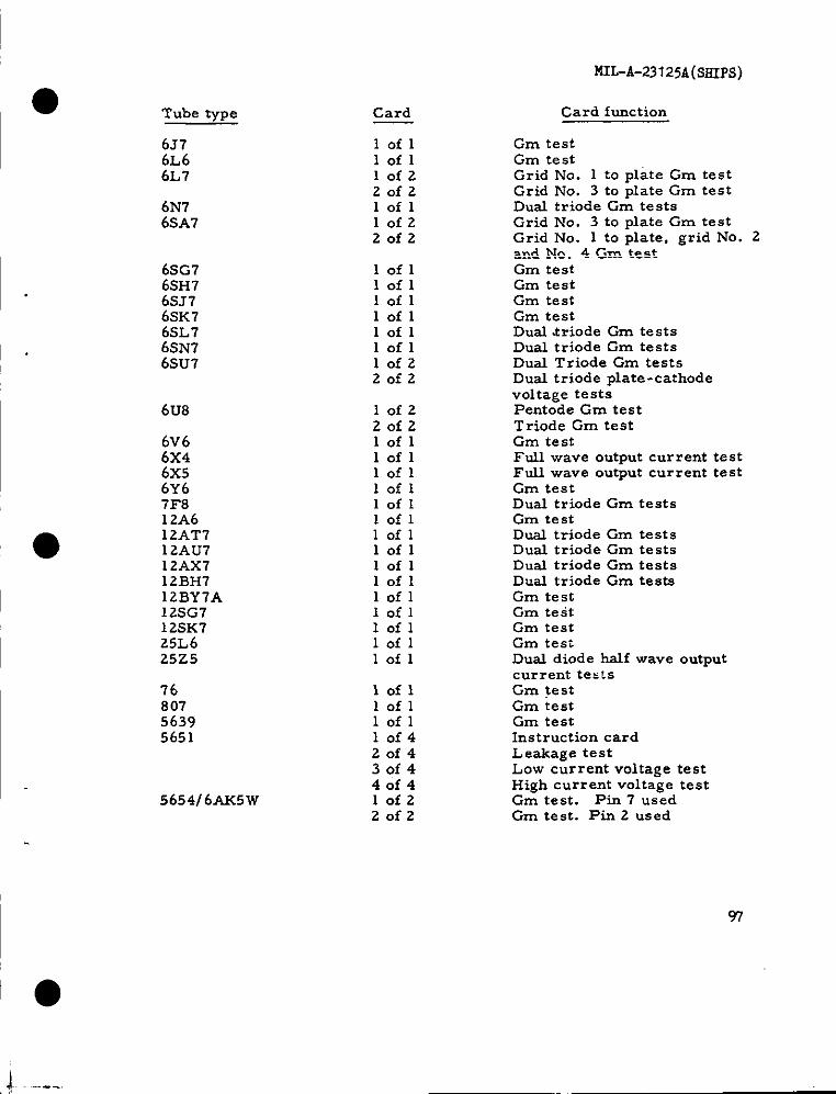
MIL-A-231 25A(SSIPS)
I
I
Tube type
6376L66L7
6N76.5A7
6SG76SH76.5J76SK76.%76SN76SU7
6u8
6V66X46x56Y67F812A612AT712AU712AX712BH712BY7A12SG712SK725L625z5
7680756395651
565416 AK5VJ
Card
lofllofllofzZofzIofllofzZofz
loflloflloflloflloflloflIofzZofz
lofzZofzIoflloflloflloflloflloflloflloflloflloflloflIoflIofllofllofl
lofllofllofl10f420f430f440f4lofzZofz
Card function
Gm testGm testGrid No. 1 to ulate Gm testGrid No. 3 to ~late Gm testDual triode Gm testsGrid No. 3 to plate Gm testGrid No. 1 to plate, grid No. Zand No. 4 Gm testGm testGm testGm testGm testDual .triode Gm testsDual triode Gm testsDual Triode Gm testsDual triode plate-cathodevoltage testsPentode Gm testTriode Gm testGm testFull wave output current testFull wave output current testGm testDual triode Gm testsGm testDual triode Gm testsDual triode Gm testsDual triode Gm testsDual triode Gm testsGm testGm testGm testGm testDual diode half wave outputcurrent testsGm testGm testGm testInstruction cardLeakage testLow current voltage testHigh current voltage testGm test. Pin 7 usedGm test. Pin 2 used
97
J.------

MIL-T-23125A(SHIPS)
Tube type
5663
567o5686
5687
5691569256935696
57025703
570457185719
572516AS6W
572616AL5W572712D21W
5744
5749] 6BA6W575016BE6W
57515763
5784
5814A5829584o
98
Card
10f3z0f330f3lofl10f320f330f310f220f2loflloflIofl1’ of 320f330f3lofl10f320f330f31 of 1lofl10f320f330f310f220f2lofl10f320f330f310f22of2lofl10f220f2
lofl10f220f210f220f2lofllofl10f320f330f3
Card function
Plate current testPlate-cathode voltage testPlate current cut-off testDual triode Cm testsGm testPlate current testPlate-cathode voltage testDual triode Gm testsDual tr’iode plate current testsDual triode Gm tests’Dual triode Gm testsGm testCathode kurrent testPlate -cathcde voltage testPlate current cut-off testGm testGm testPlate current testPlate cur rent cut -off testHalf wave output current testGm testGm testPlate current testPlate current cut-off testGrid No. 1 to plate Gm testGrid No. 3 to plate Gm testDual diode plate current testsPlate current testPlate - cathode voltage testPlate current cut-off testGm testPlate current cut-off testGm testGrid No. 3 to plate Gm testGrid No. 1 to plate, grid No. 2and No. 4 Gm. testDual triode Cm testsGm test. Pir. 9 used.Gm test. Pin S usedGrid No. 1 to plate Gm testGrid No. 3 to plate Cm testDual triode Gm. testsDual diode pla~e current testsGm testPlate current testPlate current cut -off test
. .
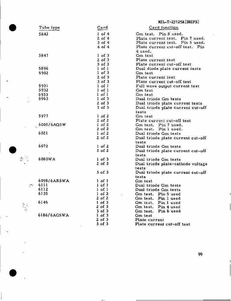
Tube type
5842
5847
58965902
5931593259335963
5977
, 6005/ 6AQ5w
6021
6072
-. .-,. 6080wA
6098 f6AR6wAa- 6111
61126135
6146
6186/ 6AG5wA
Card
10f42of430f440f4
10f320f330f3lofl10f32of330f3lofllofllofl10f320f330f3
lofz20f2lofzZofzlofzZofz
10f220f2
10f320f3
30f3
lofllofllofllofz20f210f320f330f310f320f330f3
MIL-’l’-23l25A(SJfIPS)Card function
Gm test. Pin 8 used.Plate current test. Pin 7 used.Plate current test. Pin 5 used.Plate durrent cut-off test. Pin4 used.Gm testPlate current testPlate current cut-off testDual diode plate current testsGm testPlate current testPlate current cut-off testFull wave output current testGm testGm testDual triode Gm testsDual triode plate current testsDual triode plate current cut-offtestsGm testPlate currcct cut-off testGm test. Pia 7 used.Gm test. Pin 1 used.Dual triode Gm testsDual triode plate current cut-offtestsDual triode Gm testsDual triode plate current cut-offtestsDual triode Gm testsDual triode plate-cathode voltagetestsDual triode plate current cut-offtestsGm testDual triode’ Gm testsDual triode Gm testsGm test. Pin 5 usedGm test. Pin 1 usedGm test. Pin 1 usedGm test. Pin 4 usedGm test. Pin 6 usedGm testPlate currentPlate current cut-off test
99

MILT-231 25A(SHIPS)
~
Tube type
9001
9003
I
Card
lofzZofzlofzZofz
Card function
Gm test. Pin 7 usedGm test. Pin 2 usedGrn test. Pin 7 usedGm test. Pin 2 used
●
100
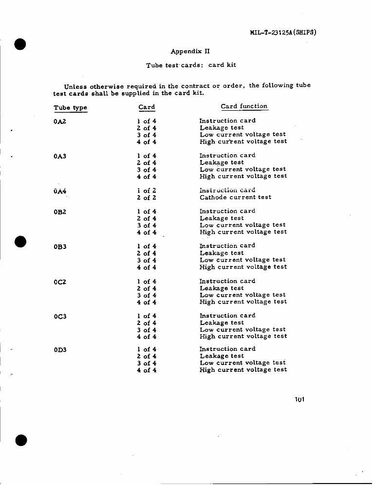
MIL-T-23125A(SHIPS)
Appendix 11
Tube test cards: card kit
Unless otherwiserequiredinthecontractor order, thefollowingtubetestcards shall be supplied in the card kit.
Tube type Card Card function
0A2 10f4 Instruction card20f4 Leakage test30f4 Low current voltage test40f4 High cur>ent voltage test
0A3 10f4 Instruction card20f4 Leakage test30f4 Low current voltage test4of4 High current voltage test
OA4 10f2 Instruction card20f2 Cathode current test
0B2 10f4 Instruction card20f4 Leakage test30f4 Low current vo~tage test40f4
●High current voltage test
0B3 10f4 ~struction card20f4 Leakage test30f4 Low current voltage test40f4 High current voltage test
0C2 10f4 Instruction card20f4 Leakage test30f4 Low current voltage test40f4 High current voltage test
0C3
0D3
10f420f430f440f4
10f420f430f440f4
Instruction cardLeakage testLow current voltage testHigh current voltage test
Instruction cardLeakage testLow current voltage testHigh current voltage test
101
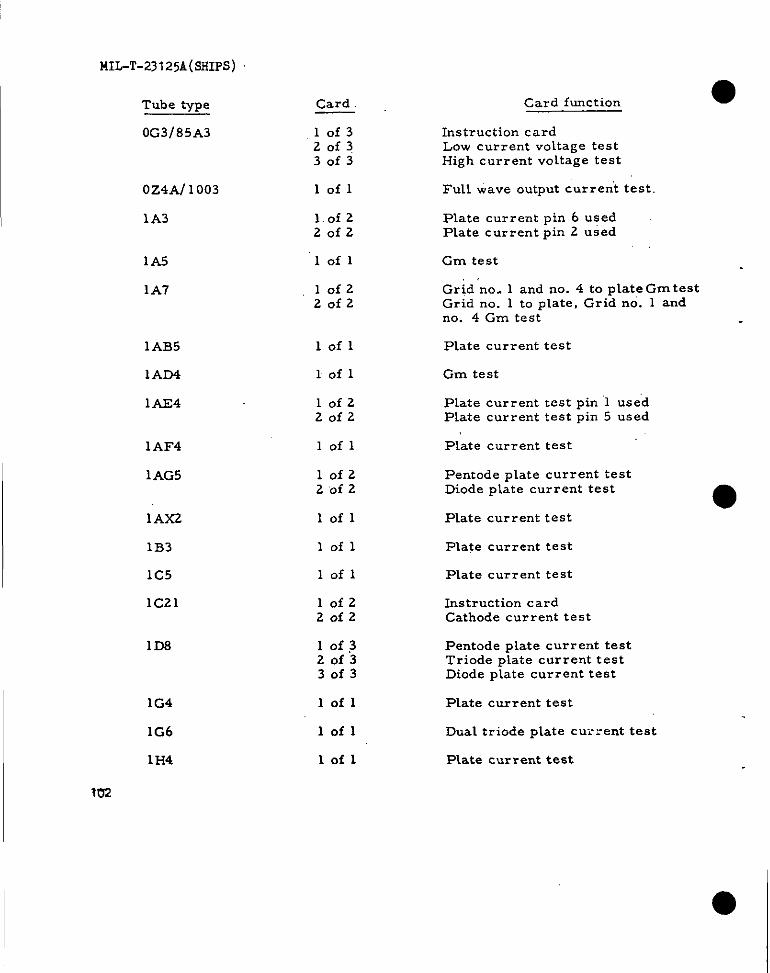
141L-T-23125A(SHIPS)
Card Card function
Instruction cardLow current voltage testHigh current voltage test
Full wave output current test
Tube type
0G3/85A3 .10f320f330f3
0z4At 1003
1A3
lofl
1.0f220f2
Plate current pin 6 usedPlate current pin 2 used
1A5
1A7
lofl Gm test
Grid ‘no. 1 and no. 4 to plate Gm testGrid no. 1 to plate, Grid no. 1 andno. 4 Gm test
,10f220f2
1AB5
1AD4
1AE4
lofl
1 of 1
Plate current test
Gm test
Plate current test pin 1 usedPlate current test pin 5 used
Plate current test
10f220f2
lofl1AI?4
1AG5 10f22 ‘of 2
lofl
Iofl
Pentode plate current testDiode plate current test
1AX2
1B3
1C5
1C21
Plate current test
Plate current test
lofl Plate current test
10f220f2
Instruction cardCathode current test
1D8 10f320f330f3
Pentode plate current testTriode plate current testDiode plate current test
1G4
1G6
1?34
lofl Plate current test
lofl
Lofl
Dual triode plate current test
Plate current test
I ?02

● Tube type
1H5
1J3
1K3
1L4
1L6
1LA4
lLA6 ‘“” “’
1LB4
1LC5
1LC6
● ‘ ~~~~1LD5 ,,
1LE3
1LH4
1LN5
1N5
.,,1P5
1Q5
lR4/1294
Card
lofzZofz
lofl
lofl
lofl
lofzZofz
lofl
l’0f2Zofz
lofl
lofl
lofzZofz
lofzZofz
lofl
lofzZofz
lofl
lofl
lofl
lofl
lofl
MIL-T-23125A(SHIPS)
Card function
Triode plate current testDiode plate current test
Plate current test
Plate current test
Gm test
Grid no. land no. 4to plate GmtestGrid no. lto plate, grid nO. 3 andno. 5 Gm test
Gm test
Grid no. 1 and no. 4 to plate Gm testGrid no. Lto p~ate, grid no. 3 andno. 5 Gm test
Gm test
Gm test
Grid no. 1 and no. 4to ptate GmtestGrid no. 1 to plate, Grid no. 3 andno. 5 Gm test
Pentode plate current testDiode plate current test
PLate current test
Triode plate current testDiode plate current te’st
Grn test
Gm test
Gm test
Plate current test
Plate current test
103
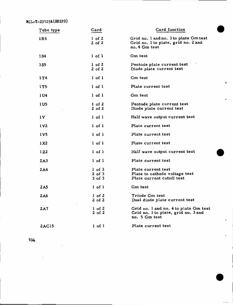
I llIL-T-23125A(SFl~S)
Tube type
1R5
1s4
1S5
1T4
1T5
1U4
1U5
lV
1V2
1V5
1x2
1Z2
2A3
2A4
2A5
2A6
2A7
2AC15
Iw
Card
10f220f2
lofl
10f220f2
lofl
lofl
lofl
10f220f2
lofl
lofl
lofl
lofl
lofl
lofl
10f320f330f3
lofl
Iofz20f2
10f220f2
lofl
Card function
Grid no. 1 and no. 3 to plate Gm testGrid no. 1 to plate, grid no. 2 andno. 4 Gm test
Gm test
Pentode plate current testDiode plate current test
Gm test
Plate current test
Gm test
Pentade plate current testDiode plate cur rent test
Half wave output current test
Plate current test
Plate current test
Plate current test
Half wave output current test
Plate current test
Plate current testPlate to cathode voltage testPlate current cutoff test
Gm test
Triode’Gm testDual diode plate current test
Grid no. 1 and no. 4 to plate Gm testGrid no. 1 to plate, grid no. 3 andno. 5 Gm test
Plate current test
●
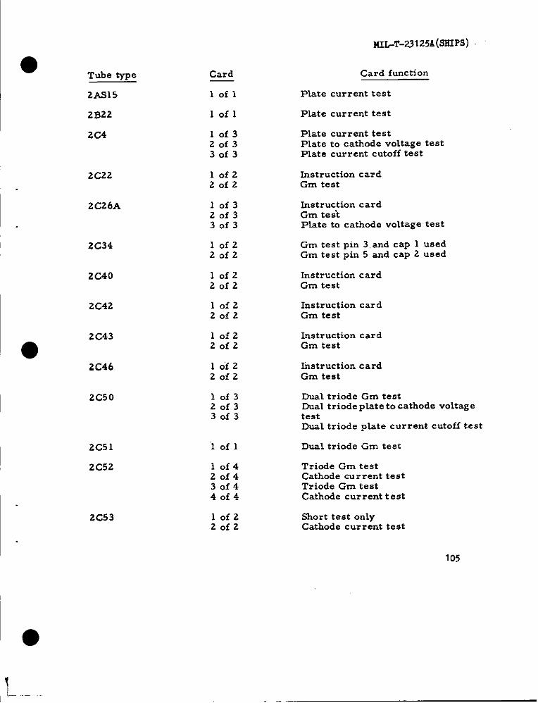
MI.-T-23l25ii(SSIPS)
●Tube type
2AS15
2B22
2C4
2C22
2C26A
2C34
2C40
2C42
2C43
2C46
2C50
2C51
2C52
2C53
Card
lofl
lofl
10f320f330f3
10f220f2
10f320f330f3
10f220f2
10f220f2
10f220f2
10f220f2
10f220f2
10f320f330f3
lofl
10f420f430f440f4
10f220f2
Card function
Plate current test
Plate current test
Plate current testPlate to cathode voltage testPlate current cutoff test
Instruction cardGm test
Instruction cardGm teskPlate to cathode voltage test
Gm test pin 3.and cap 1 usedGm test pin 5 and cap 2 used
Instruction cardGm test
Instruction car dGm test
Instruction cardGm test
Instruction cardGm test
Dual triode Gm testDual t riode pkte to cathode voitag etestDual triode plate current cutoff test
Dual triode Gm test
Triode Gm testCathode current testTriode Gm testCathode current test
Short test onlyCathode current test
105
,1.—

1“ MIL-T-23125A(s5ups)
Tube type
2D21
2E22
2E24
2E25
2E26
2E30
2E31
2E35
2GZ 1
2X2A
3A4
3A5
3B2
3B4
3B7
3B24
3D611299
Card
10f320f330f3
10f220f2
10f320f330f3
Iofl
1 ‘of” 320f330f3
lofl
lofl
lofl
10f220f2
lofl
10f220f2
10f220f2
lofl
10f220f2
lofl
10f22 of “2
lofl
Card function
Plate current testPlate to cathode voltage testPlate current cutoff test
Piate current testPlate to cathode voltage test
Plate c’urrent test pin 6 usedPlate ccrrent test pin 4 usedPlate to cathode voltage test
Plate current test
Gm test pin 6 us?dGm test pin 4 usedPlate to cathode voltage test
Plate current test
Plate current test
Plate current test
Pentode plate current testTriode plate current test
PLate current test
Gm test pin 6 usedGm test pin 2 used
Gm test pins 5 and 6 usedGm test pin 2 and 3 used
Plate current test
Plate current testScreen current test
Dual triode plate current test
Plate current test. >:IIS 1 and 2 usedP~ate ctirrent test. Pins 1 and 4 used
Plate current test
106
I
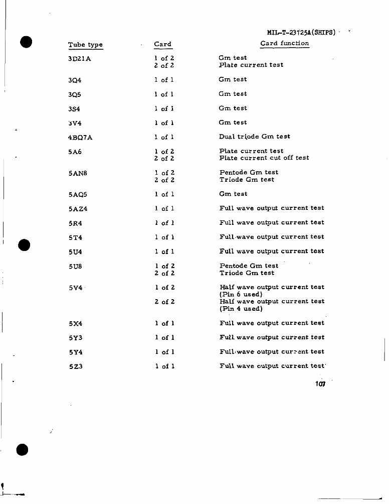
Tube type
3D21A
3Q4
3Q5
3.S4
3V4
4BQ7A
5A6
5AN8
5AQ5
5AZ4
5R4
●5T4
5U4
5u8
5V4
5x4
5Y3
5Y4
5Z3
Card
10f220f2
lofl
lofl
lofl
lofl
lofl
10f2z0f2
10f220f2
lofl
lofl
lofl
lofl
lofl
10f220f2
10f2
20f2
lofl
Iofl
lofl
iofl
MIL-T-231’25A(SSIPS) “
Card function
Gm testPlate current test
Gm test
Gm test
Gm test
Gm test
Dual tri.ode Gm test
Plate current testPlate current cut off test
Pentode Gm testTriode Gm test
Gm test
Futl wave output current test
Full wave ou@ut current test
Full wave output current test
Full wave output current test
Pentode Gm testTriode Gm test
Half wave output current test(Pin 6 used)HaLf wave output current test(Pin 4 used)
Full wave output current test
FuIL wave output current test
Full, wave output cur=ent test
Full wave output current test
Itm
I
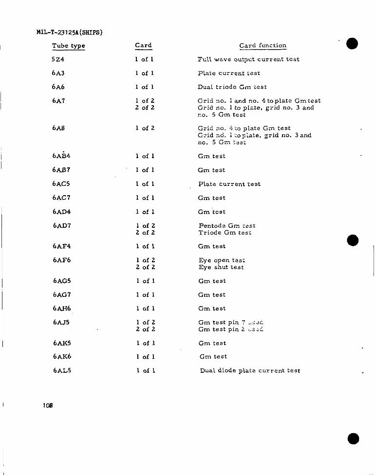
MILT-23I25Ji(smps)
Tube type
5Z4
Card
lofl
Card function
Ftll wave outpct current test
6A3
6A6
lofl
lofl
Plate cu:rent tzst
Dual triode Gm test
6A7 lofzZofz
C-ri5 :?0. i and no. 4top~ate GmtestGrid no. 1 to plzte, grid no. 3 andrm. 5 Gm test
6A8 lofz Grid ao. +20 plzte Gm testC.zid z6. i m~bte, grid no. 3 andno. 5 Gm tsst
Gm test6AB4
6AB7
6Ac5
6Ac 7
6AD4
6AD7
lofl
lofl
lofl
Gm test
Plate cur= ent test
lofl
lofl
Gm test
Gm test
lofzZofz
Pentode Gm testTriode Gm test
0,6AF4
6AF6
Iofl
lofzZofz
lofl
Gzn test
Eye open t..:Eye shut test
6AG5
6AG7
6AH6
6AJ5
Gm test
lofl
lofl
lofzZofz
Gm test
Gm test
Gm test pin 7 <s~tiGm test pin 2 ,Msi
6AK5
6AK6
6AL5
lofl
lofl
lofl
Gm test
Grn test
Dual diode plate current test
I 10S
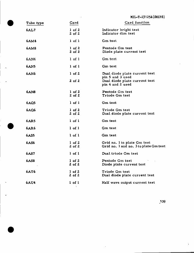
● Tube type
6AL7
MIL-T-23125A(SSIPS)
Card. function
Indicator bright testIndicator dim test
Card
10f220f2
6AM4
6A&f8
lofl Gm test
10f220f2
Pentode Gm testDiode plate current test
6AN4
6AN5
6AN6
lofl Gm test
lofl Gm test
10f2 Dual diode plate current testpin 5 and 3 usedDual diode plate current testpin 4 and 2 used
Pentode Gm testTriode Gm test
20f2
6AN8 10f220f2
6AQ5
6AQ6
lofl Gm test
10f220f2
Triode Gm testDual diode plate current test
6AR5
● 6AR6
lofl Gm test
lofl Gm test
6AS5
6AS6
lofl Gm test
Grid no. 1 to plate Gm testGrid no. 1 and no. 3 to plate Gmtest
10f220f2
6ASI
6AS8
lofl Dual triode Gm test
10f220f2
Pentode Gm testDiode plate current test
Triode Gm testDua~ diode plate current test
6AT6 10f220f2
6AU4 lofl Half wave output current test
.1Cq

MIL-T-23 125A(SHIPS)
Tube type
6AU5
Card
10f220f2
Card function “:
Grn testPlate current knee test
6AU6
6AU8
lofl Gm test
lofz2 Of.2
Pentode Gm testTriode Gm test
6AV5 10f220f2
Gm testPlate current test
6AV6,,.
6AX4
6AX5
6B4
6B7
10f220f2
Triode GIII testDuaL diode piate current test
lofl Half wave output current test
lofl Full wave output current test
Iofl Plate current test
10f220f2
Pentode Gm testDual diode plate current test
6B8 10f220f2
lofl
Pentode Gm testDual diode plate current test
6BA5
6BA7
Gm test
10f220f2
Grid no. 3 to plate Gm testGrid no. 1 to plate grid no. .2and no. 4 Gm test
6Bc4
6Bc5
6Bc7
lofl C-m test
lofl Gm test
lofz20f2
Diode plate current testDual diode plate current test
633D6
6BE6
lofl Gm test
10f220f2
Grid no. 3 to plate Gm testGrid no. 1 to plate. grid no. 2and no. 4 Gm test
110
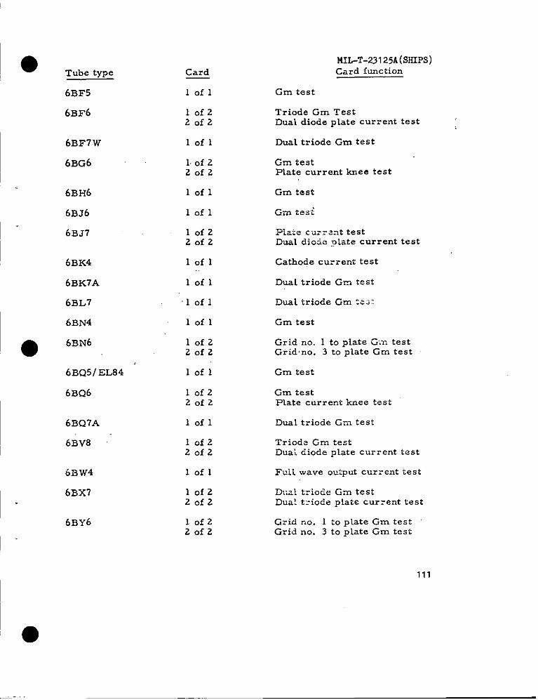
● Tube type Card
lofl
MIL-T-23125A(SHIPS)Card function
Cm test613F5
6BF6 lofz20f2
Triode Gm TestDual diode plate current test
Dual triode Gm test6BF7W
6BG6
Iofl
Gm testPlate current knee test
1 of 220f2
6BH6
6BJ6
6BJ7
lofl Gm test
Gin tesilofl
10f220f2
.Pla:e c.u:z-znt testDuaL dimic p:ate current test
6BK4
6BK7A
6BL7
6BN4
lofl
lofl
Cathode current test
Dual triode Gm test
,1of 1 Dual triodeGm ZCZ.:
lofl Gm test
6BN6●10f220f2
Grid no. 1 to plate Gm testGiidno. 3 to plate Gm test
6BQ51EL84
6BQ6
lofl Gm test
10f220f2
Gm testPlate current knee test
6BQ7A lofl Dual triode Grn test
6BV8 10f220f2
Triode Gm testDuai diode plate current test
6BW4
6BX7
lofl l%il wave output cur=ent test
lofz20f2
Dual triode C-m testDual t:iode plate current test
6BY6 lofz20f2
Grid no. 1 to plate Gm test “Grid no. 3 to plate Gm test
111
●

MIL-T-23 125A(SHIPS)
Tube type
6BZ6
6C4
6C5
6C6
6C8
6C336
6CD6
Card
lofl
lofl
Card function
Gm test
Gm test
Gm testIofl
lofl
lofl
lofl
lofz2of2
Gm test
Dual triode Gm test
Gm test
Gm testPlate current knee test
6GG7
6CL6
6GM6
6GM8
Dual triode Gm test
lofl Gm test
lofl Gm test
Pentode Gm testTriode Gm test
10f220f2
6CQ8 lofz20f2
Pentode Gm testTriode Gm test
6CS6 lofz20f2
Grid no. 1 to plate Gm testGrid no. 3 to plate Gm test
6CY5
6CZ5
6D4
Iofl Gm test
Gm testlofl
10f320f330f3
Cathode current testPlate to cathode voltage testP~at e :crient cut oif test
6D6
6DC6
6DE6
6DK6
lofl Gm test
lofl Gm test
lofl Gm test
IOfl Gm test
112
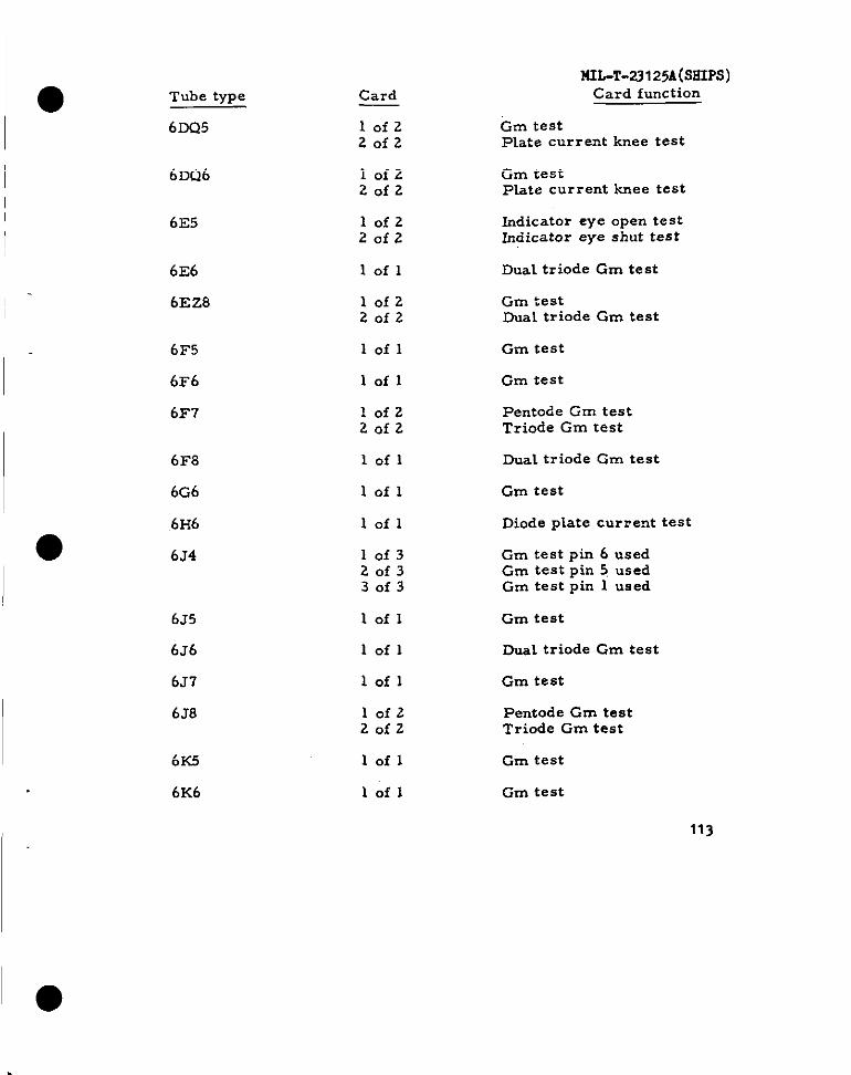
Tube type
6DQ5
Card
MU-T-23125A(ssm)Card function
Gm testPlate current knee test
lofzZofz
6DQ6 lofzZofz
Gm testPlate current knee test
6E5 lofzZofz
Indicator eye open testIndicator eye shut test
DuaL triode Gm test6E6
6Ez8
lofl
lofzZofz
Gm testDW1 triode Gm test
6F5
6F6
6F7
lofl Gm test
lofl Gm test
lofzZofz
Pentode Gm testTriode Gm test
Dual triode Gm test6F8
6G6
6H6
6J4
lofl
Gm test
Diode plate current test
lofl
lofl
10f320f330f3
Gm test pin 6 usedGm test pin 5 usedGm test pin 1 used
6J5
6J6
6J7
6J8
lofl Gm test
Dual triode Gm testlofl
lofl Gm test
lofzZofz
Pentode Gm testTriode Gm test
6K5
6K6
lofl Gm test
lofl Gm test
113
I ●
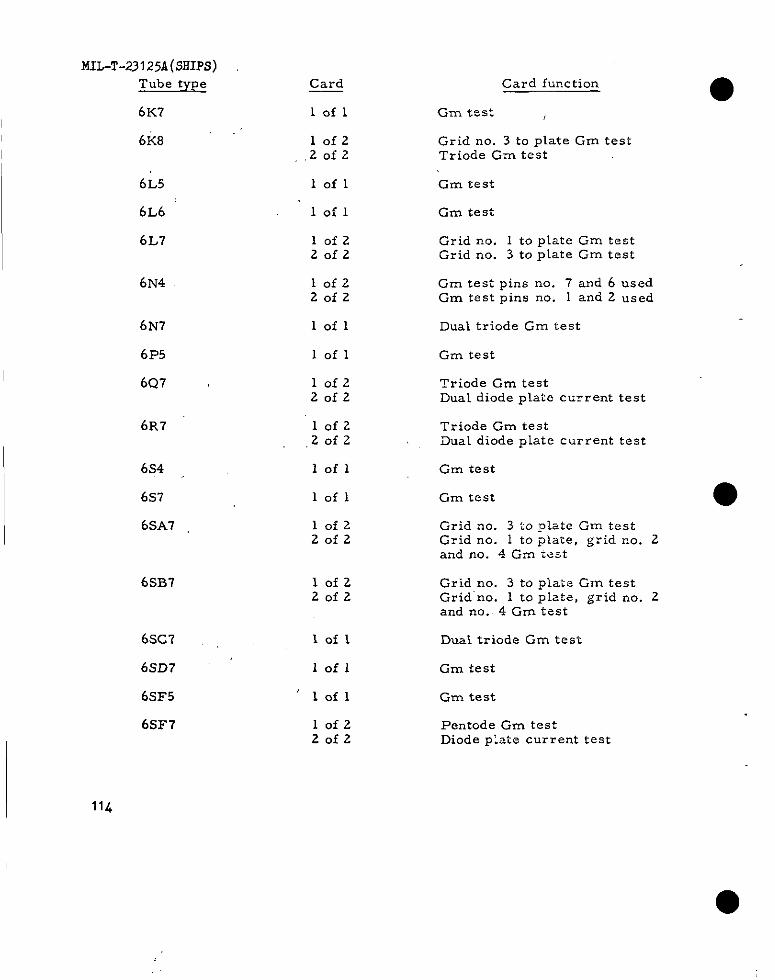
MIL-T-231 25A (SHIPS)
Tube type
6K7
Card
lofl
Card function
Gm test ,
6K8 lofz,,zofz
Grid no. 3 to plate Gm testTriode Gm test
6L5
6L6 ‘
6L7
lofl Gm test
Gm testlofl
lofzZofz
Grid no. 1 to plate Gm testGrid no. 3 to plate Gm test
6N4 lofzZofz
Gm test pins no. 7 and 6 usedGm testpinsno. 1 and 2 used
6N7
6F’5
6Q7 ~
lofl Dual triode Gm test
lofl Gm test
lofz20f2
Triode Gm testDual diode plate cu~rent test
6R7 lofz,Zofz
Iofl
lofl
Triode Gm testDual diode plate current test
6s4
6s7
6sA7
Gm test
Gm test
10f2Zofz
Grid rm. 3 to plate C-m testGrid no. 1 to plate, grid no. 2and no. 4 Gm test
6.5B7 lofzZofz
Grid no. 3 to plate Gm testGrid no. 1 to plate, grid no. 2and no.. 4 Gm test
6SC7
6sD7
6s3?5
6S3?7
lofl
lofl
‘ lofl
Dual triode Gm test
Gm test
Gm test
lofzZofz
Pentode Gm testDiode piate current test
L
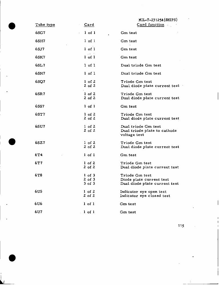
Tube type
6SG7
6SH7
6S.17
6SK7
6SL7
6SN7
6SQ7
6SR7
6SS7
6sT7
6SU7
● 6S27
6T4
6T7
6T8
6u5
6U6
6U7
@rg
lofl
lofl
1 oil
Iofl
lofl
lofl
10f220f2
10f22 of 2
lofl
10f220f2
10f22of2
10f220f2
lofl
10f220f2
10f320f330f3
10f220f2
lofl
lofl
MIL-T-23125A(sHIPs)Card function
Gm test
Gm test
Gm test
Gm test
Dual triode Gm test
Dual triode Gm test
Triode Gm testDual. diode plate current test
Triode Gm testDual diode ,pLate current test
Gm test
Triode Gm testDual diode plate current test
Dual triode Gm testDual triode plate to cathodevOLtage test
Triode Gm testDual diode plate current test
Gm test
Triode Gm testDual diode plate current test
Triode Gm testDiode plate current testDual diode plate current test
Indicator eye open testIndicator eye closed test
Gm test
Gm test
115
I ●
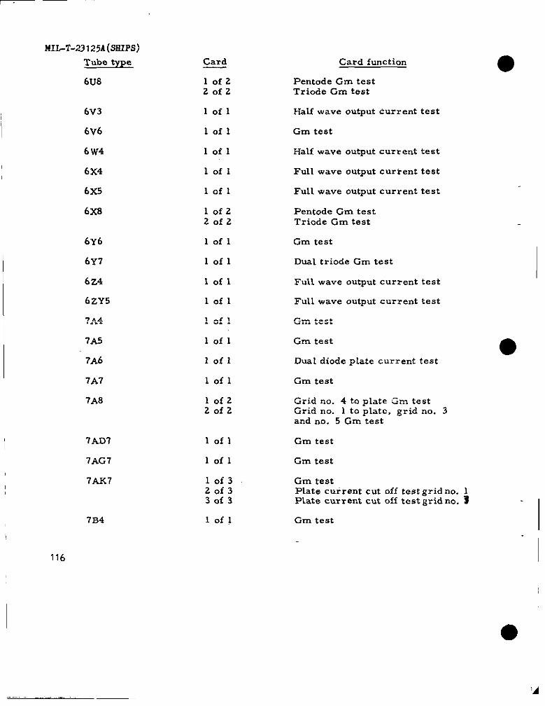
-
MIL-T-23125A(SHIPS)Tube type
6u8
6v3
6V6
6 W4
6x4
6x5
6x8
6yb
6Y7
6z4
6zY5
7A4
7AS
7A6
7A7
7A8
7AD7
7AG7
7AK7
7B4
116
Card
lofzZofz
lofl
lofl
lofl
lofl
lofl
lofz20f2
lofl
lofl
Iofl
lofl
lofl
lofl
Iofl
lofl
lofzZofz
lofl
lofl
10f320f330f3
lofl
Card function
Pentode Gm testTriode Gm test
Half wave output current test
Gm test
Half wave output curt ent test
Full wave output current test
Full wave output current test
Pentode Gm testTriode Gm test
Gm test
Dual triode Gm test
Full wave output current test
Full wave output current test
Gm test
Gm teat
Dual diode pIate current test
Gm test
Grid no. 4 to plate Gm testGrid no. 1 to plate, grid no. 3and rm. 5 Cm test
Gm test
Gm test
Gm testPlate cuirent cut off test grid no. 1Plate current cut off test grid no. 3
Gm test I
‘A
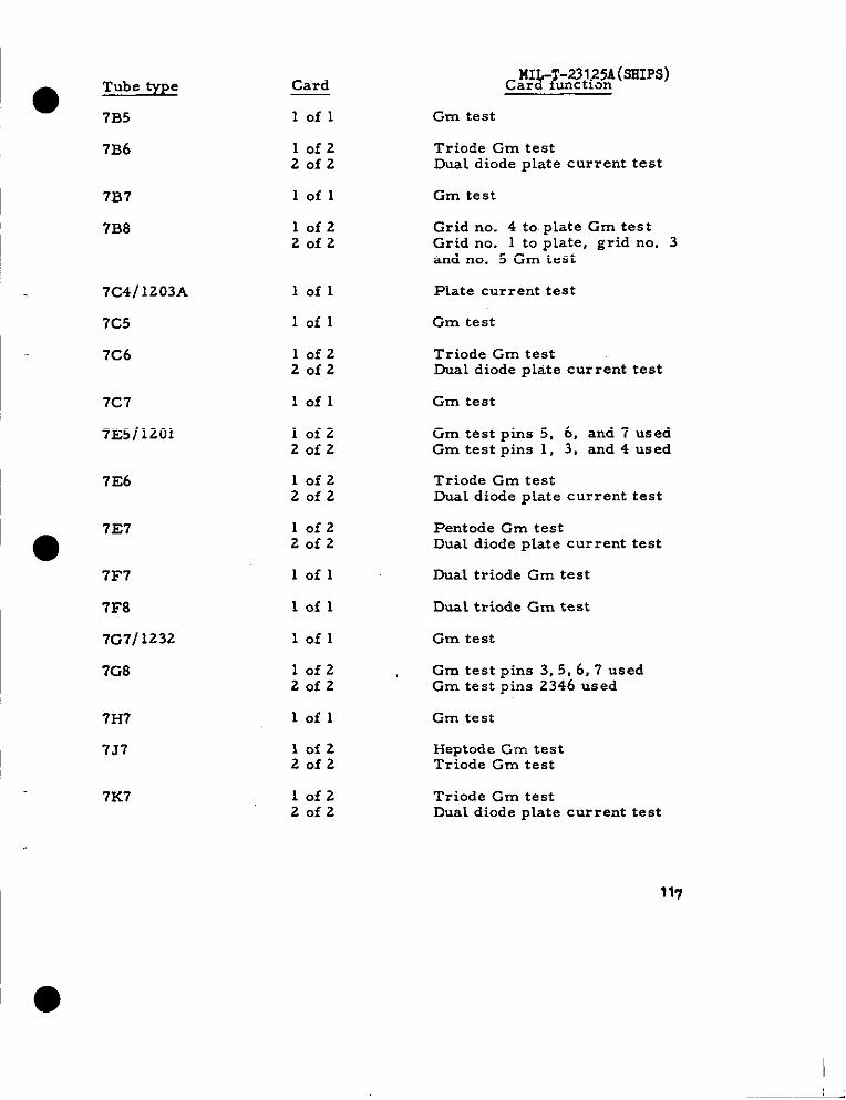
●Tube ~pe
7B5
Card
lofl Gm test
7B6 lofzZofz
Triode Gm testDual diode plate current test
7B7
713s
lofl Gm test
10f220f2
Grid no. 4 to plate Gm testGrid no. 1 to plate, grid no. 3and no. 5 Gm test
7C4/1203A
7C5
7C6
lofl Plate current test
lofl Gm test
lofzZofz
Triode Grn testDual diode plate current test
lofl Gm test7C7
7E5/1201 lofzZofz
Gm test pins 5, 6, and 7 usedGm test pins 1, 3, and 4 used
7E6 lofz20f2
Triode Gm testDual diode plate current test
7E7
●lofzZofz
Pentode Gm testDual diode plate current test
lofl Dual triode Gm test7F7
7F8
7G7/ 1232
7GS
lofl Dual triode Gm test
lofl Gm test
Gm test pins 3, 5, 6, 7 usedGm test pins 2346 used
lofz ,20f2
7H7
7J7
lofl C-m test
10f220f2
Heptode Gm testTriode Gm test
10f220f2
7K7 Triode Gm testDual diode plate current test
117
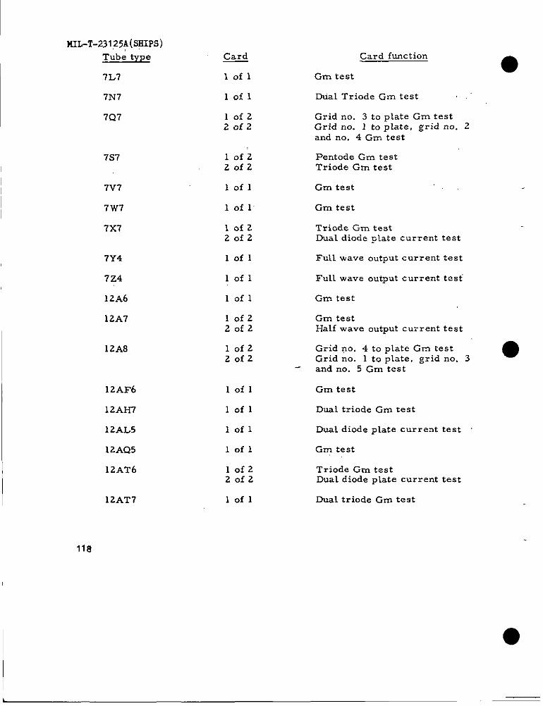
141L-T-23125A (SHIPS)
Tube type
7L7
7N7
7Q7
7s7
7V7
7W7
7X7
7Y4
7Z4
12A6
12A7
12A8
12AF6
12AH7
12AL5
12AQ5
12AT6
12AT7
118
~
lofl
lofl
10f220f2
1.of 22of2
lofl
1 of 1
10f220f2
lofl
lofl
lofl
10f220f2
10f220f2
lofl
lofl
lofl
lofl
10f220f2
lofl
Card function
Gm test
Dual Triode Gm test ,,.
Grid no. 3 to plate Gm testGrid no. 1 to plate, grid no. 2and no. 4 Gm test
Pentode Cm testTriode Gm test
Gm test
Gm test
Triode Gm testDual diode @ate current test
Full wave output current test
Full wave output current test
Gm test
Gm testHalf wave output current test
Grid no. 4 to plate Gm testGrid no. 1 to plate, grid no. 3 ●and no. 5 Gm test
Gm test
Duai triode Gm test
DuaL diode plate current test
Gm test
Triode Gm testDual diode plate current test
Dual triode Gm test
L
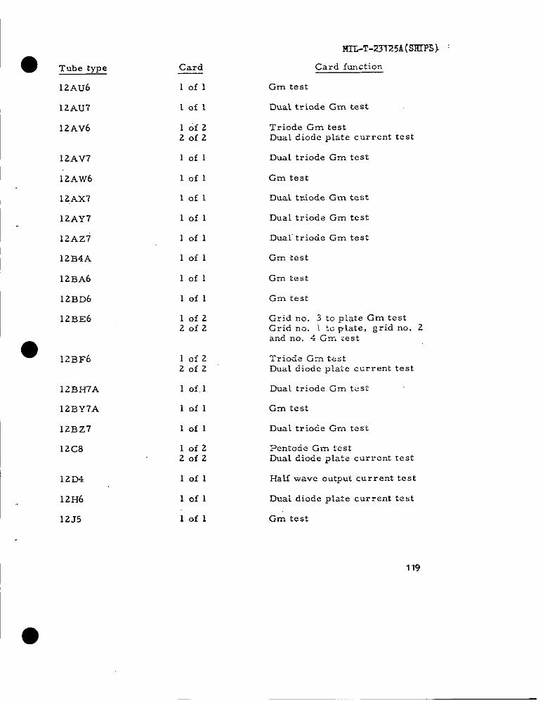
● ‘rub type
12AU6
12AU7
12AV6
12AV7
12Av?6
12Ax7
12AY7
12AZ7
12B4A
12BA6
12BD6
12BE6
● 1223F6
12BH7A
12BY7A
12Bz7
12C8
12D4
12H6
12J5
Card
lofl
lofl
10f220f2
lofl
lofl
lofl
lofl
lofl
lofl
lofl
lofl
10f220f2
10f220f2
1 Of.1
lofl
lofl
10f220f2
lofl
lofl
lofl
MTL-T-231Z51@HIF3) ‘
Card function
Gm test
Dust triode Gm test
Triode Gm testDual diode plate current test
Dual triode Gm test
Gm test
Dust tr.iode Gm test
Dual triode Gm test
Dualtriode Gm test
Gm tsst
Grn test
Grn test
Grid no. 3 to plate Gm testGrid no. 1 t-~ plate, grid no. 2and no. 4 Gn-. test
‘Triocie G= testDual diode plate ctirrent test
Dual triode Gm test
Gm iest
Dual triode Gm test
Pentorie Gm testDual diode plate current test
Half wave output current test
Duai diode p~ate current test
Gm test
119
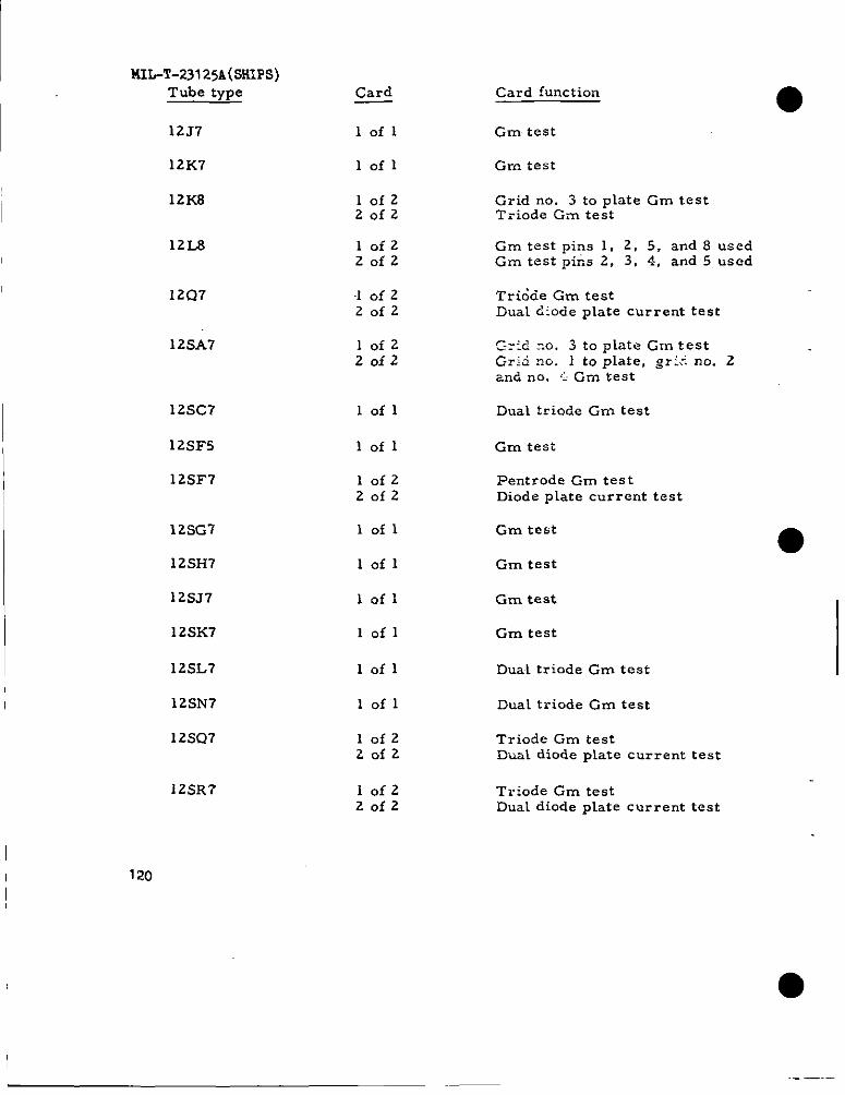
MIL-T-2312sA(SSXPS)Tube type
12J7
12K7
12K8
Card Card function
lofl Gm test
lofl Grn test
10f220f2
Grid no. 3 to plateGm testTriode Grn test
12L8 10f220f2
Gm testpins 1, 2, 5, and 8 usedGm test pim 2, 3, 4, and 5 used
12Q7 .1 of 220f2
Tri&ie Gm testDual &iocle plate current test
12sA7 10f220f2
C:::d :0. 3 to plateGm testGrki no. 1 toplate,griino. 2znd no. ‘1Gm test
12sC7
12SF5
12SF7
lofl Duai triode Gm test
lofl Gm test
lofz20f2
Pentrode Cm testDiode plate current test
12SG7
12sI-17
12SJ7
12SK7
12SL7
12sN7
12SQ7
lofl Gm test
lofl Gm test
lofl Gm test
lofl Gin test
lofl DuaL triode Gm test
lofl Dual triode Gm test
10f220f2
Triode Gm testDual diode plate current test
12SR7 10f220f2
Triode Gm testDual diode plate current test
120
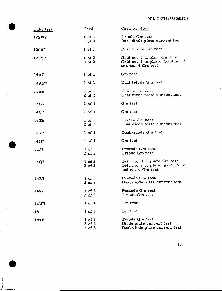
W+W3125A(SRIPS)
● Tube type
12SW7
Card f~action
T~iode Gzn testDual dioiep!atecurrenttest
Card
lofzZofz
12sx7
12SY7
lofl
IofzZofz
Grid no. ? tc plate Gm testGrid no. 1 to plate, Grid nO. 2and no. 4 Gm test
lofl Gm test14A7
14AF7
14B6
Dual triode Gm test
Triode Gm testDual diode piate current test
Iofl
lofzZofz
lofl Gm test14C5
14C7
14E6
‘1of 1 Gm test
Triode Gm testDual diode plate current test
lofzZofz
lofl DuaL triode Gm test14F7
●14H7
14J7
lofl Gm test
Pentode Gm testTriode Gm test
lofzZofz
lofzZofz
Grid no. 3 to ptate Gm testGrid no. 1 to plate, grid no. 2and no. 4 Gm test
14Q7
lofzZofz
Pentode Gm testDual diode plate current test
14R7
lofz20f2
Pentode Gm testT:-iode Gm test
14s7
14W7 1 of 1 Gm test
Gm test
Triode Gm testDiode plate current testDual diode pLate current test
.15 Iofl
10f320f3
19T8
30f3
121
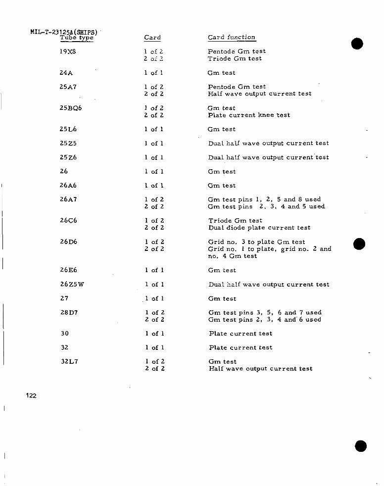
MIL-T-23125A(SHIPS)Tube type
19XS
Card
lcfi2oi?
Card function
PentodS Gm testTriode Gm test
24A
25A7
lofl Gm test
lofz20f2
Pentode Gm testI-IaLf wave output current test
25BQ6 IOfz2of2
Gm testPlate current knee test
25L6
25z5
25’z6
26
26A6
26A7
lofl
lofl
Grn test
Dual half wave output current test
lofl
lofl
lofl
Dual, ha:f wave output current ‘test
Gm test
Gm test
Gm test pins 1, 2, 5 and S usedGm test pins 2, 3, 4 and 5 used
lofzZofz
26C6 lofzZofz
Triode Gm testDual diode p~ate current test
Grid no. 3 to plate Gm testGrid no. I to piate, grid no. 2 and ●no. 4 Gm test
26D6 lofz20f2
26E6
26z5w
27
2SD7
lofl Gm test
lofl Dual half wave output current test
lofl Gm test
lofz20f2
Gm test pins 3, 5, 6 and 7 usedGm test pins 2, 3, 4 and’6 usedI
30
32
32L7
lofl Plate current test
lofl Plate current test
10f220f2
Gm testHalf wave output current test
122
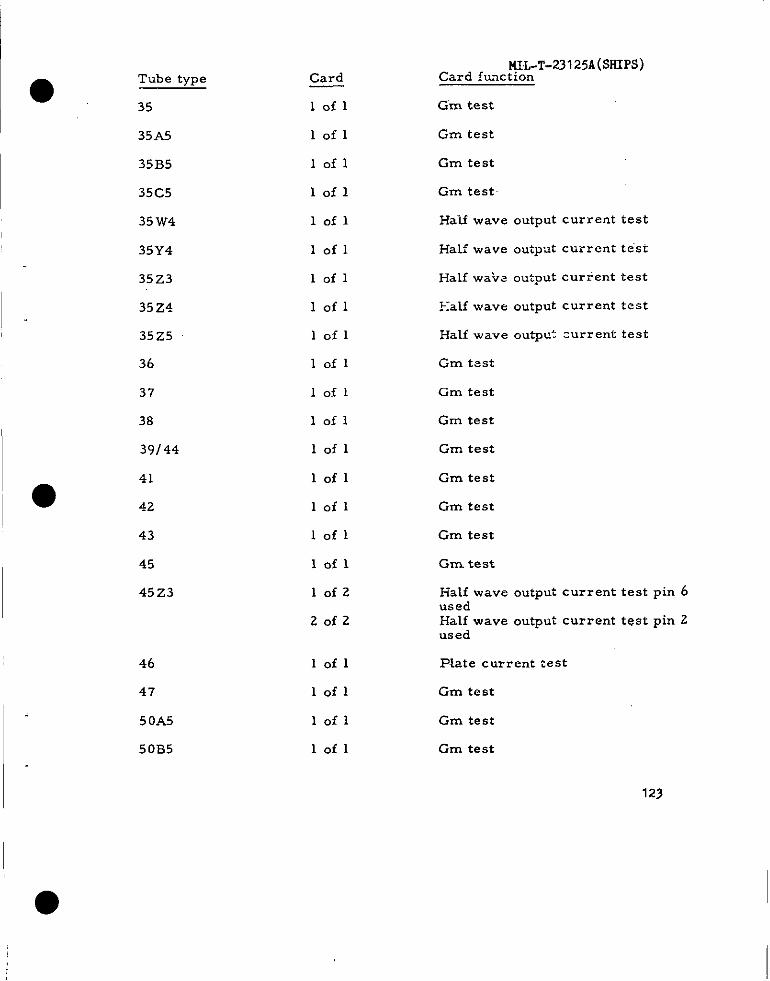
●
----
Tube type
35
35A5
35B5
35C5
35 W4
35Y4
35 Z3
35 Z4
35Z5
36
37
38
39/44
41
42
43
45
45Z3
46
47
5OA5
50B5
Card
lofl
lofl
lofl
lofl
lofl
lofl
lofl
lofl
lofl
lofl
lofl
lofl
lofl
lofl
lofl
lofl
lofl
10f2
Zofz
lofl
lofl
lofl
lofl
Gm test
Gm test
Gm test
Gm test
Ha-Lf wave output current test
Half wave output currenttest
Halfwa?s outputcurrenttest
~:alf ~ave output current test
Halfwave outputcurrenttest
Gm test
Gm test
Gm test
Gm test
Gm test
Gm test
Gm test
Gm. test
Ha~f wave output current test pin 6usedHalf wave output current test pin 2used
Plate current test
Gm test
Gm test
Gm test
123
I
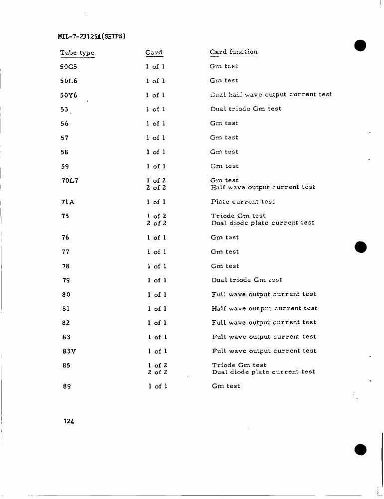
MIL-T-23125A(SHIFS)
Tube type
50C5
50L6
50Y6
53,
56
57
58
59
i’0L7
71A
7“5
76
77
78
79
so
S1
82
83
83V
85
89
Card
l.of 1
loii
lofl
lofl
lofl
lofl
lofl
lofl
IofzZofz
lofl
Iofz20f2
lofl
lofl
lofl
lofl
lofl
lofl
lofl
lofl
lofl
lofzZofz
lofl
Cam? f.<nction
Gm testi
Gm test
C.r.aLha;.! wave output current test
Dual tziaic+ Gm test
Gm test
am test
C-m test
Gm testHalf wave output current test
Plate cm-rent test
Triocle Gm testDual diode plate current test
Gm tc?st
Gm test
Gm test
Dual triode Gm iest
Fu’!i wave output cwrent test
Half wave output current test
Full wave outpu: current test
Full wave output current test
Full wave output current test
Triode Gm testDual diode plate current test
Gm test
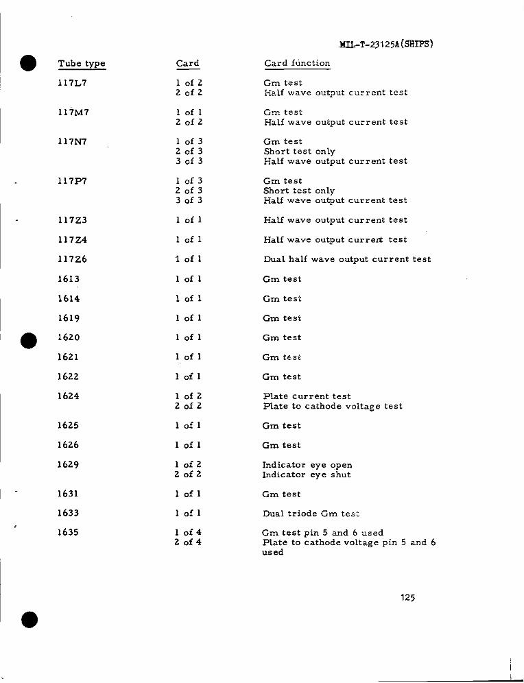
ML-T-231 25A(-
Card f tine tion
Gm testHalf wave output current test
● ‘rub. type Card
lofzZofz
117L7
117M7
117N7
117P?
117Z3
117Z4
117z6
1613
1614
1619
loflZofz
Gm. testHalf wave output current test
10f320f33of3
Gm testShort test onlyHalf wave output current test
10f320f330f3
Gm testShorttestonlyHatfwave outputcurrenttest
lofl Half wave output current test
lofl Half wave output current test
1 of 1 Dual half wave output current test
lofl Gm test
lofl Gm test
lofl Gm test
Gm test● 1620 lofl
1621
1622
1624
lofl Gm test
Gm testlofl
lofzZofz
Plate current testPlate to cathode voltage test
lofl Gm test
Gm test
625
626
629
631
lofl
lofzZofz
Indicator eye openIndicator eye shut
lofl Gm test
Dual triode Gm test1633 lofl
1635
●
10f420f4
Gm test pin 5 and 6 usedPlate to cathode voltage pin 5 and 6used
125

MIL-T-23125A(SSIPS)
Tube type
1635 (Conlt. )
1641
1851
2050
2051
5618
5636
5639
5641
5642
5643
5644
5647
Card
30f440f4
lofz
Zofz
lofl
10f320f330f3
10f320f330f3
lofl
lofzZofz
lofl
10f3
20f3
30f3
lofl
10f320f330f3
10f420f430f440f4
lofzZofz
Card function
Gm test pin 3 and 4 usedPlate to cathode voltage pin 3 and 4used
Half wave output current test Cap 1usedHalf wave output current test cap 2used
Gm test
Plate current testPlate, to cathode voltage testPlate current cutoff test
Plate current testPlate to cathode voltage testPIate current cutoff test
Gm test
Grid no. 1 to plate Gm testGrid no. 3 to plate Gm test
Gm test
Half wave output current test pin 8 ●usedHalf wave output current test pin 4used.
Half wave output current test
Plate current test
Plate current testPlate to cathode vo~tage testPlate current cutoff test
Instruction cardLeakage testLow current voltage testHigh current voltage test
Instruction cardHalf wave output current test
126
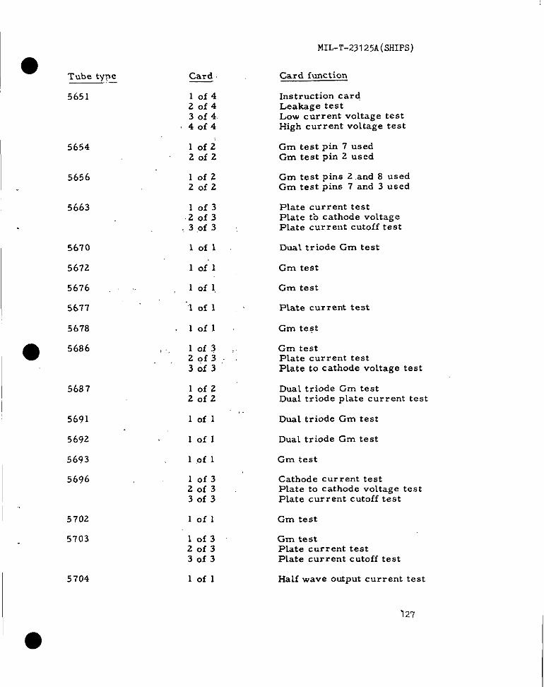
5651
5654
5656
5663
5670
5672
5676 ~~
5677
567’8
5687
5691
5692
5693
5696
5702
5703
5704
Card
10f420f430f440f4
lofz20f2
lofz20f2
10f3.20f3
,, 3 ,Of 3
lofl
lofl
1 of 1,
“’lof 1
lofl
, . 10f320f330f3
lofz20f2
lofl
lofl
1 .Of 1
10f320f330f3
Iofl
lof320f330f3
lofl
MIL-T-23125A(SHIPS)
Card function
Instruction cardLeakage testLow current voltage testHigh current voltage test
Gm test pin 7 usedGm test pin 2 used
Gm test pins 2 and 8 usedGm test pins 7 and 3 used
Plate current testPlate tb cathode voltageP~ate current cutoff test
Dual triode Gm test
Gm test
Gm test
Plate current test
Gm test
Gm testPlate current testPlate to cathode voltage test
Dual triode Cm testDuai triode plate current test
Dual triode Gm test
Dual triode Gm test
Cm test
Cathode current testPlate to cathode voltage testPlate current cutoff test
Cm test
Gm testPlate current testPlate current cutoff test
Half wave output current test
~27
I●
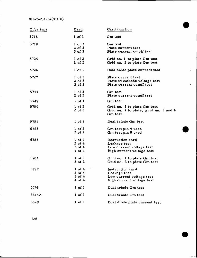
MIL-T-23125A(SHIPS)
Tube type
5718
5719
5725
5726
5727
5744
5749
5750
5751
5763
5783
5784
5787
‘5798
5814A
5829
Card
lofl
10f320f330f3
lofz20f2
lofl
10f320f330f3
lofz20f2
lofl
10f2‘?Ofz
Iofl
10f220f2
10f420f430f440f4
lofz20f2
10f42of430f440f4
lofl
lofl
lofl
Card function
Gm test
Gm testPlate current testPlate current cutoff test
Grid no. 1 to plate Gm testGrid no. 3 to plate Gm test
Dual diode plate current test
Plate current testPlate tci cathode voltage testPlate current cutoff test
Gm testPlate current cutoff test
Gm test
Grid no. 3 to plate Gm testGrid no. 1 to plate, grid no. 2 and 4Gm test
Dual triode Gm test
Gm test pin 9 usedGm test pin 8 used
Instruction cardLeakage testLow current voltage testHigh current voltage test
Grid no. 1 to plate Gm testGrid no. 3 to plate Gm test
Instruction cardLeakage testLow current voltage testHigh current voltage test
Dual triode Gm test
Dual triode Gm test
Dual diode plate ‘current test
128
●
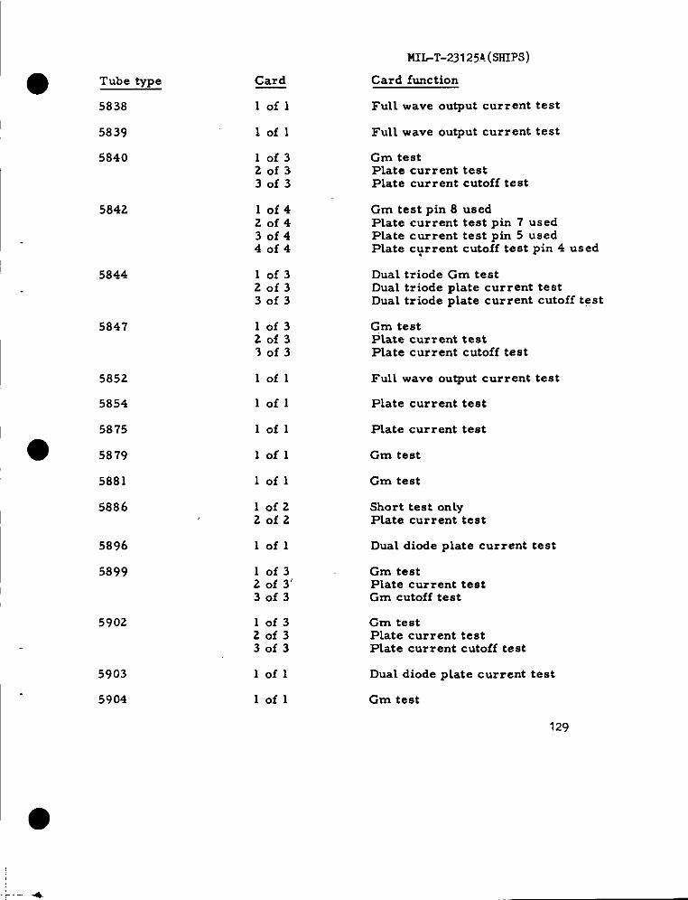
MIL-T-231 25A.(SSIPS)
Card function
Full wave output current test
● Tube ~pe
5838
Card
lofl
lofl Full wave output current test
Gm testPlate current testPlate current cutoff test
5839
5840 10f320f330f3
5842 10f420f430f440f4
Gm test pin 8 usedPlate current test pin 7 usedPlate current test pin 5 usedPlate c+rrent cutoff test pin 4 used
5844 10f320f330f3
10f320f330f3
Dual triode Gm testDual triode plate current testDual triode plate current cutoff test
5847 Gm testPlate current testPlate current cutoff test
5852 lofl Full wave output current test
5854 lofl Plate current test
5875
● 5879
lofl Plate current test
Gm testlofl
5881 lofl Gm test
Short test onlyPlate current test
5886 10f220f2
5896 lofl Dual diode plate current test
5899 10f32 of 3’30f3
Gm testPlate current testGm cutoff test
5902 10f320f330f3
Gm testPlate current testPlate current cutoff test
5903
5904
lofl Dual diode plate current test
lofl Gm test
129

ML-T-231 25A(.51fIPs)
Tube type
5905
5906
5915
5930
5931
5932
5933
5963
5964
5965
5977
5987
Card ‘
lof3z0f330f3
1.0f320f330f3
10f420f4”3of44 af’4
lofl
Iofl
lofl
‘,1 of 1’
10f32 of ‘330f3
10f320f330f3
10f320f330f3
lofzZ,ofz
1“of 3’20f330f3
5992 lofzZofz
5993 1 .Of 1
6004,.-
i0f2
!,Zofz
Card function
Gm testPLate current testPlate current cutoff test
Gm testPlate current testPLate current cutoff test
Gm testPlate current testPlate current cutoff testPlate current cutoff test
Plate current test
Fuli wave output current test
Gm test
Gm test
Dual triode Cm testDual triode plate current testDual triode plate current cutoff test
Dual triode Gm testDual triode plate current testDual triodeplate current cutoff test
Dual triode Gm testDud triode ptate current testDual triode plate current cutoff test
Gm testPlate current cutoff test
Gm test pin 8 usedGm test pin 4 usedPlate current test pin 2 used
Gm testPlate current test
Full wave output current test
Half wave output current testcap 1 usedHalf wave output current testcap 2 used
● ’
130
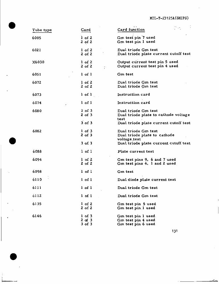
MIL-T-23125A(SHIPS)
>. .,. :Card function
Gm test pin”7 usedGm test pin .1 used
Tube type
6005
Card
iofz20f2
6021 10f220f2
Dual triode Gm testDual triode plate current cutoff test
x6030 lofz20f2
Output current test pin 5 usedOutput current test pin 4 used
6051
6072
lofl Gm test
10f2Zofz
Dual triode Gm testDual triode Gm test
6073
6074
6080
lofl Instruction card
lofl Instruction card
k0f320f3
Dual triode Cm testDual triode plate to cathode voltagetestDual triode plate current cutoff test30f3
6082 10f320f3
Dual triode Gm testDua~ triode plate to cathodevoltage ,testDual triode ptate current cutoff test● 30f3
6088
6094
lofl Plate current test
Gm test pins 9, 6 and 7 usedGm test pins 4, 1 and 2 used
lofzZofz
6098
6110
6111
0112
6135
lofl Gm test
lofl Dual diode plate current test
Dual triode Gm testlofl
Dual triode Gm test
10f220f2
Gm test pin 5 usedGm test pin.1 used
6L46 lof32af330f3
Gm test pin 1 usedGm test pin 4 usedGm test pin 6 used
131
— --
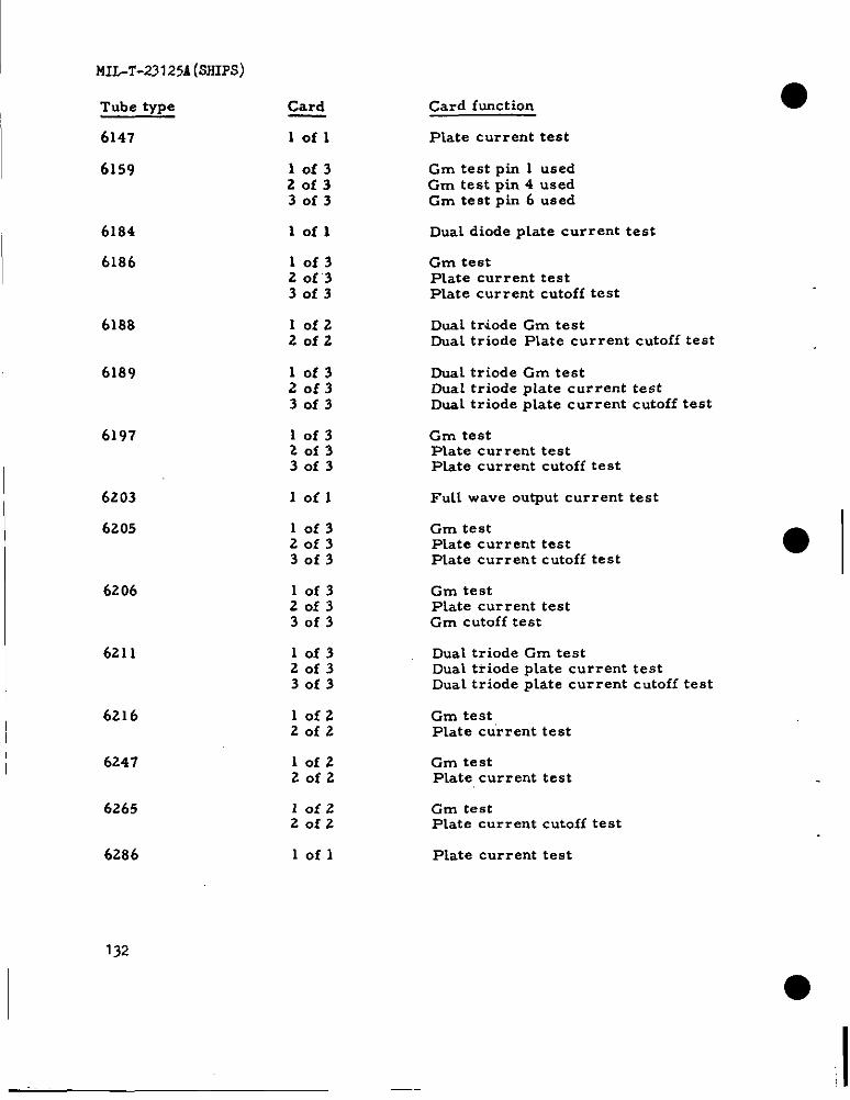
MIL-’L’-23I 254 (SSIPS)
Tube type
6147
6159
6184
6186
6188
6189
6197
6203
6205
6206
6211
6216
6247
6265
6286
Card
lofl
10f320f330f3
lofl
10f32 Of’330f3
lofzZofz
10f320f330f3
10f320f330f3
Iofl
10f320f330f3
10f320f330f3
10f320f330f3
lofz20f2
10f220f2
10f220f2
lofl
Card function
Plate current test
Gm test pin 1 usedGm test pin 4 usedGm test pin 6 used
Dual diode plate current test
Gm testPlate current testPlate current cutoff test
Dual triode Gm testDual triode Plate current cutoff test
Dual triode Gm testDual triode plate current testDual triode plate current cutoff test
Grn testPlate current testPlate current cutoff test
FuU wave output current test
Gm testPLate current testPLate current cutoff test
Gm testPLate current testGm cutoff test
Dual triode Gm testDuaL triode pLate current testDual triode pLate current cutoff test
Gm testPlate current test
Gm testPLate current test
Gm testPlate current cutoff test
Plate current test
●
132
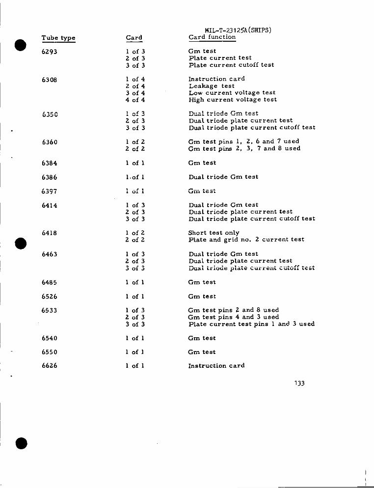
●Tube type
6293
6308
6350
6360
6384
6386
6397
6414
6418
●6463
6485
6526
6533
6540
6550
6626
Card
10f320f330f3
10f420f430f440f4
10f320f330f3
10f220f2
lofl
l.of 1
lofl
10f320f330f3
lofz20f2
10f320f330f3
lofl
lofl
10f320f330f3
lofl
lofl
lofl
MIL-T-23125A(smps)Card function
Gm testPlate current testPlate current cutoff test
Instruction cardLeakage testLow current voltage testHigh current voltage test
Dual triode Gm testDual triode ptate current testDual triode plate current cutoff test
Gm test pins 1, 2, 6 and 7 usedGm test pins 2, 3, 7 and 8 used
Gm test
Dual triode Gm test
Gm test
Dual triode Gm testDual triode plate current testDual triode plate current cutoff test
Short test onlyPlate and grid no. 2 current test
Dual triode Gm testDual triode plate current testDual triode plate current cutoff test
Gm test
Gm test
Gm test pins 2 and 8 usedGm testpins4 and 3 usedPlatecurrenttestpins 1 and 3 used
Gm test
Gm test
Instruction card
133
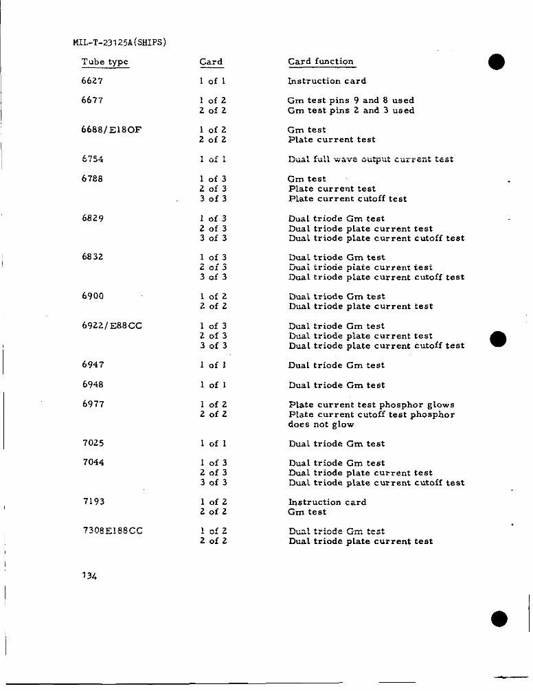
MIL-T-23125A(SHIPS)
Tube type
6627
6677
66881E180F
Card
lofl
10f220f2
10f2
Card function
Instruction card
Gm test pins 9 and 8 usedGm test pins 2 and 3 used
Gm testPlate current testZofz
loflI 6754 Dual full wave output current testI6788
6829
I 6832
6900
10f320f33of3
Gm testPlate current testPlate current cutoff test
10f320f330f3
Dual triode Gm testDual triode plate current testDual triode plate current cutoff test
10f320f3
Dust triode Gm testDual triode plate current testDual triode plate current cutoff test30f3
10f220f2
Dual triode Gm testDual triode plate current test
6922/ E88CC 10f320f330f3
Dual triode Gm testDual triode plate current testDual triode plate current cutoff test ●
6947
6948
6977
lofl Dual triode Gm test
Dual triode Gm testlofl
lofz20f2
Plate current test phosphor glowsPlate current cutoff test phosphordoes not glow
7025
7044
lofl Dual triode Gm test
10f320f330f3
Dual triode Gm testDual triode plate current testDual triode pLate current cutoff test
7193
7308 E188CC
10f220f2
Instruction cardGm test
lofzZofz
Dual triode Gm testDual triode plate current test
13&
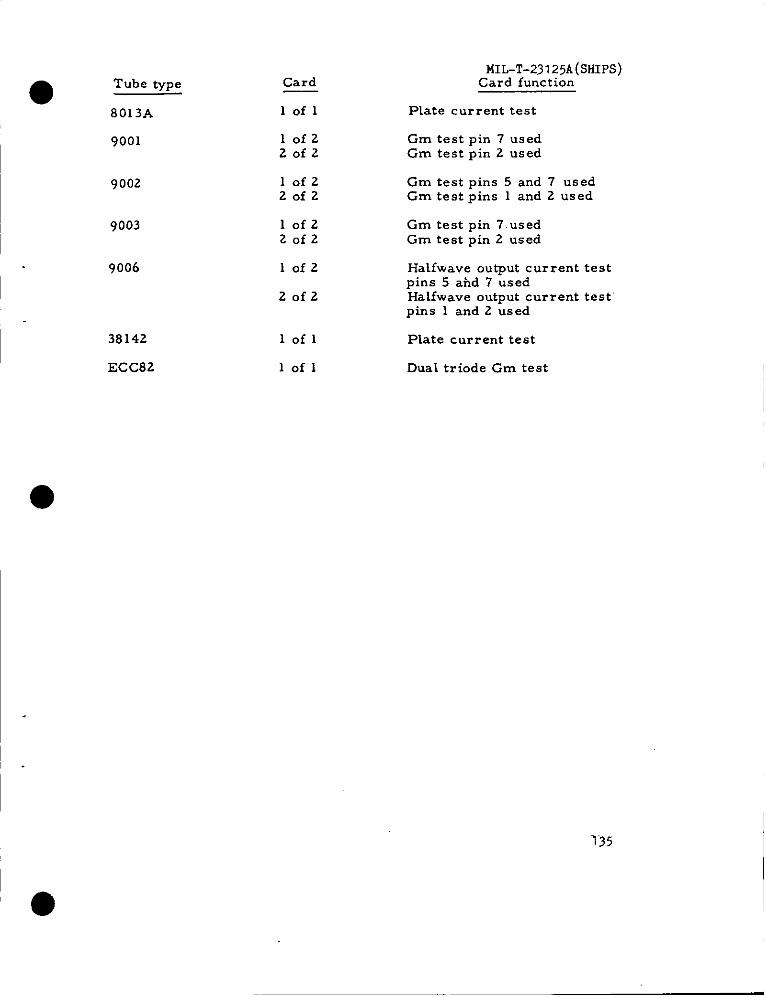
Tube type
● —8013A
9001
I 9002
I 9003
9006
38142
ECC82
Card
lofl
lofzZofz
lofzZofz
lofzZofz
lofz
Zofz
lofl
lofl
MIL-T-231 25A (SFiIPS3)Card function
Plate current test
Gm test pin 7 usedGm test pin 2 used
Gm testpins 5 and 7 usedGm testpins 1 and 2 used
Gm test pin 7.usedGm test pin 2 used
Halfwave output current testpins 5 ahd 7 usedHalfwave output current test”pins 1 and 2 used
Plate current test
Dual triode Gm test
“135

MIL-T-23125A(SHIPS)
136
.
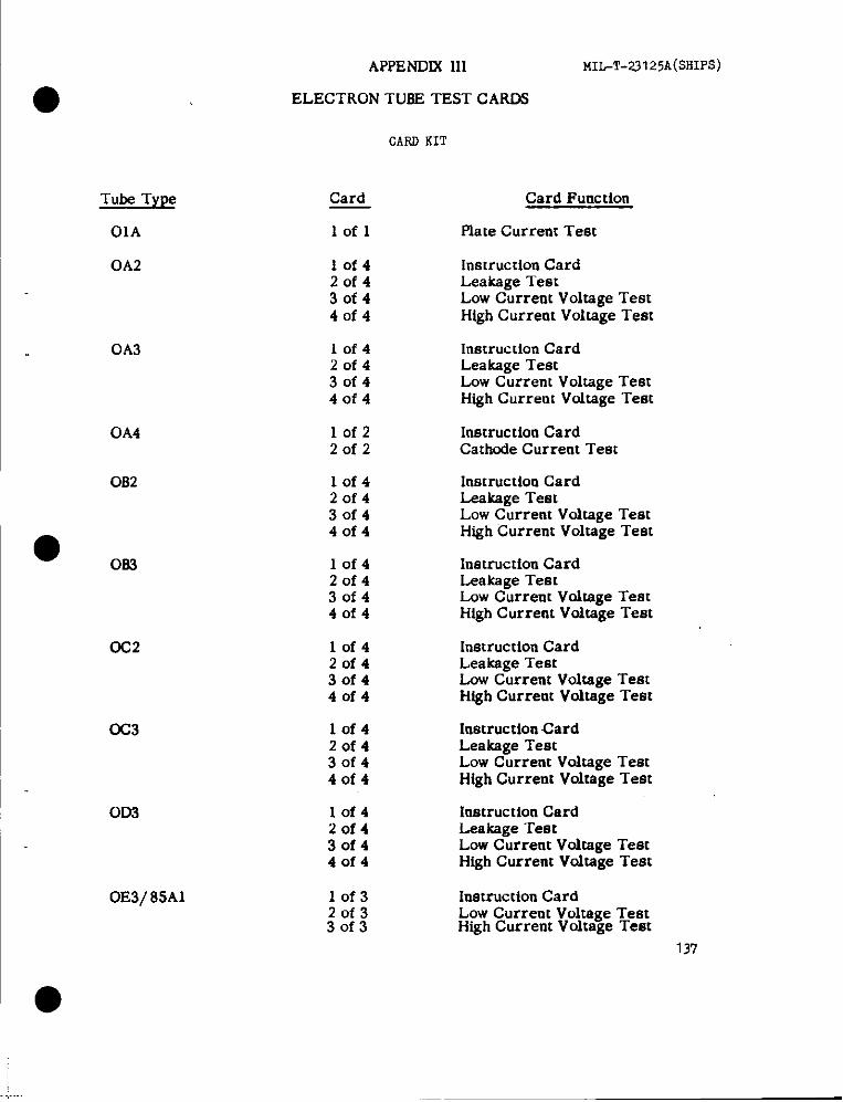
Tube TYLW
OIA
0A2
I 0A3
0A4
0B2
●063
0C2
0C3
0D3
0E3/ 85A1
APPENDIX111 MIL-T-23125A(SHIPS)
ELECTRON TU3E TEST CAROS
Card
lofl
10f420f43of440f4
10f420f430f44of4
10f2Zofz
lof420f430f44of4
10f420f430f440f4
10f42of430f440f4
lof42of430f44of4
10f42of43of440f4
10f320f330f3
CARIIKIT
Card Function
Pia[e Current Test
Instruction CardLeakage lestLow Current Voltage TestHigh Currem Voltage ‘Test
Instruction CardLeakage TestLow Current Voltage TestHigh Current Vultage Test
Instruction CardCathnde Current Test
Inmmction CardLeakage TestLow Current Voltage TestHigh Current Voltage Test
Instruction CardLeakage TestLow Current Vrdtage TestHigh Current Voitage Test
Instruction CardLeakage TestLow Currem Voltage TestHigh Current Voitage Test
htatruction CardLeakage TestLow Current Voltage TestHigh Current Voitage Test
Instruction CardLeakage TestLnw Current Voitage TestHigh Current Vnltage Test
Instruction CardLow Current Voltage TestHigh Current Voltage Test
137

. .. . - . . . . . . . . ... . . .MIL-I-ZjlZ~A(WilFSJ
Tube Type
0G3/ 85A2
0Z4
0Z4A/ 1003
Card
10f32of330f3
Card Function
Instruction CardLow Current Voltage TestHigh Current Voltage Teat
lofl Deal Diude Plate Current Test
.lof 1 Full Wave Output Current Teat
1A3 10f220f2
Plate Current Pin 6 usedPlate Current Pin 2 used
IA4 Iofl Plate Current Teat
Cm Test1A5
1A7 .
Iofl
lof220f2
Grid No. 1 and No. 4 to plate Cm TeatGrid No. 1 to plate, Grid No. 1 and
No. 4 Cm Teat
IoflIAB5
IAB6/DK96
Plate Current Teat
10f220f2
Grid No. 2 and Plate Current TestGrid No. 4 and Plate Current Teat
1AD4
lADS
IAE4
Iofl Cm Test
lofl Plate Current Test
.IofzZofz
Plate Current Test Pin 1 usedPlate Current Teat Pin 5 used
1AF4
IAG4 ,
1AG5
lofl Plate Current Teat
lofl Gm Test
lof220f2
Penmde Plate Current TestDiode Plate Current Test
1AH4
lAH5/DAF% ‘“
Iofl‘,
lof2,. 2 of 2
Cm Teat
Perttode Plate Current TestDiode plate Current Test
lAJ4/ DF% .,,
138
lofl plate Current Test
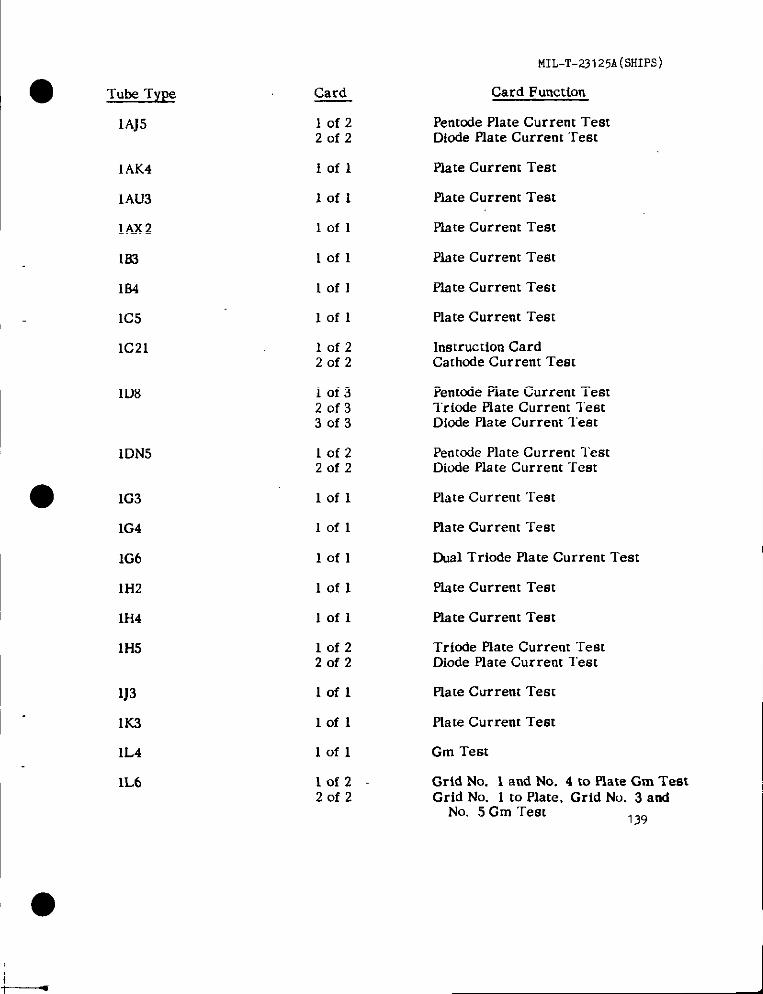
● Tube Type
1AJ5
1AK4
1AU3
1AX2
153
184
IC5
1C21
1D8
1DN5
1G3
1G4
1G6
1H2
1H4
1H5
1J3
IK3
1L4
1L6
Card
10f220f2
lofl
lofl
Iofl
lofl
lofl
lofl
10f220f2
10f320f330f3
10f220f2
lofl
Iofl
lofl
lofl
lofl
lofz20f2
lofl
lofl
lofl
10f220f2
MIL-T-23 125A(SliIR3 )
Card Function
Pentode Plate Current TestDiode Plate Current ‘rest
Plate Current Test
Plate Current Test
Plate Current Test
Plate Current Teat
Plate Current Test
Plate Current “rest
Instruction CardCathode Current Teat
Pentcde Plate Current TestTriode Plate Current TestDiode Plate Current lest
Penmde Plate Current lestDicxlePlate Current Test
Plate Current Test
Plate Current Test
Eval Trinde Plate Current Test
plate Current Test
Plate Current Test
Trbde Plate Current TeatDiode Plate Current Test
Plate Current Test
Plate Current Test
Gm Test
Grid No. 1 and No. 4 to Plate Gm TestGrid No. 1 to Plate, Grid No. 3 and
No. 5 Cm Test 139
I-
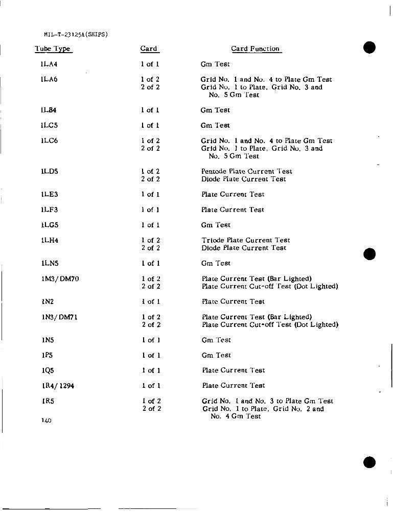
MIL-T-23I25A(SHIPSj
Tube Type
1LA4
1LA6
IL64
1LC5
1LC6
ILD5
1LE3
1LF3
lLG5
1LH4
1LN5
lM3/DM70
1N2
lN3/DM71
1N5
1P5
IQ5
lR4/ 1294
1R5
140
Card
Iofl
10f220f2
lofl
lofl
lofz20f2
lof220f2
lofl
Iofl
lofl
10f220f2
lofl
lofz20f2
Iofl
10f220f2
lofl
lofl
lofl
Iofl
lof220f2
Card Function
Gm Test
Grid No. 1 and No. 4 to Plate Gm TestGrid No. 1 to Plate, Grid No. 3 and
No. 5 Cm Test
Gm Test
Gm ‘rest
Grid No. 1 and No. 4 to Plate Cm l-estGrid No. 1 to Plate, Grid No. 3 and
No. 5 Gm Test
Pentnde Plate Current ‘lestDiode Plate Current Test
Plate Current Test
Plate Current Tes[
Cm Test
Triode Plate Current lestDiode Place Current “rest
Gm Test
Plate Curr&rt Test (Bar Lighted)Plate Current Cut-off “rest (DOILighted)
plate Current Test
Plate Current Test (Bar Lighted)Plate Current Cut-off l“est (Dot Lighted)
Gm ‘rest
Cm Test
Place Current Test
Plate Current Test
Grid No. 1 and No. 3 to Plate Cm TestGrid No. 1 to Plate, Grid No. 2 and
No. 4 Gm Test
●
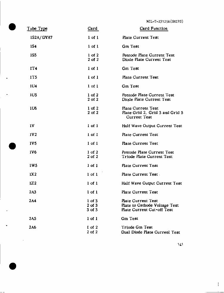
● Tube Type
M2A/ DY87
1s4
1s5
1T4
ITS
1U4
1U5
1U6
lV
1V2
1W5
1X2
lz2
2A3
2A4
2A5
2A6
Card
lofl
lofl
10f22of2
lofl
lofl
lofl
10f220f2
10f220f2
Iofl
Iofl
Iofl
10f22of2
lofl
lofl
lofl
lofl
10f320f330f3
lofl
10f220f2
MIL-T-23125A(sHIps)
Card Function
Plate Current Test
Gm Test
Pentode Plate Current TestDiode Plate Current Test
Gm Test
Plate Current Test
Gm Test
Pentcde Plate Current TestDiQdeplate Current Tem
Plate Current TestPlate Grid 2, Grid 3 and Grid 5
Current Test
Half Wave Output Current Test
Plate Current Test
Plate Current Test
Pentode Plate Current TestTriode Plate Current Test
Plate Current Teat
Plate Current Teat
Half Wave Output Current Teat
Plate Current Teat
Plate Current TestPlate to Cathode Voltage TestPlate Current Cut-off Test
Gm Test
Triode Gm TestDual Diode Plate Current Teat
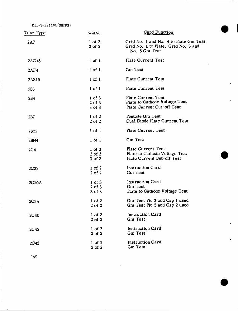
MIL-T-23125A(SHIPS)
Tube Type
2A7
2AC15
2AF4
2AS15
2B3
2B4
2B7
2B22
2BN4
2C4
2C22
2C26A
2C34
2C40
2C42
2C43
142
Card
10f220f2
lofl
‘1 of 1
lofl
lofl
10f320f330f3
lofz2of2
Iofl
lofl
10f320f330f3
lof2Zofz
10f320f33of3
10f220f2
10f220f2
lof22of2
lofz20f2
Card Function
Grid No. 1 and No. 4 to Plate Cm TestGrid No. 1 to Plate, Grid No. 3 and
No. 5 Cm Test
Plate Current Test
Gm Test
Plate Current Test
Plate Current Test
Plate Current TestPlate to Cathwie Voltage ‘restMate Current Cut-off Test
Penmde Gm TestDual Dinde Plate Current Test
Plate Current Test
Gm Test
Plate Current TestPlate to Cathcde Voltage TestPlate Current Cut-off Test
Instruction CardGm Test
Instruction CardGm ‘lestPlate to Cathnde Voltage Test
Gm Test Pin 3 and Cap 1 usedGm Test Pin 5 and Cap 2 used
Instruction CardGm “rest
Instruction CardGm Test
Instruction CardGm l-est
●
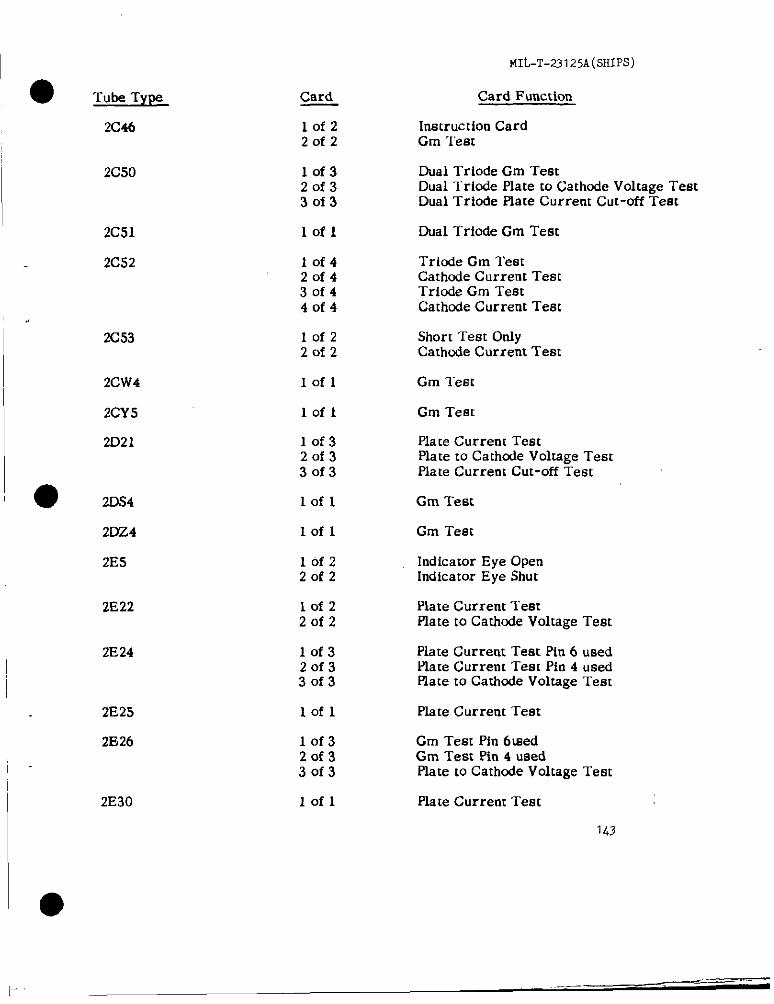
● Tube Type
2C46
2C50
2C51
2C52
2C53
2CW4
2CY5
2D21
● 2DS4
2DZ4
2E5
2!322
2E24
2E25
2E26
2E30
Card
lofz20f2
lof320f33of3
lofl
10f420f430f44of4
lofz20f2
Iofl
lofl
10f320f330f3
Lofl
Iofl
lofz2of2
lofz20f2
lof320f330f3
lofl
10f32of33of3
lofl
MILT-23125A(SHIPS)
Card Function
Instruction CardCm “1’est
Dual Triode Gm TestDual lriode Plate to Cathode Voltage TestDual Triode Piate Current Cut-off Test
Dual Triode Cm Test
Triode Gm TeatCathnde Current TestTricde Cm TestCathode Current Test
Short Test GniyCathode Current Test
Gm lest
Gm Teat
Pla [e Current TestPlate to Cathcde Voltage TestPlate Current Cut-off Test
Cm Test
Cm Test
Indicator Eye OpenIndicator Eye Shut
Piate Current TestPiate to Catimde Voltage Test
Piate Current Test Pin 6 usedPlate Current Test Pin 4 usedPlate to Carhcde Voltage Test
Piate Current Teat
Gm Test Pin 6medGm Test Ph 4 usedPlate to Cathcde Voltage Test
Hate Current Test
143
——-.l..
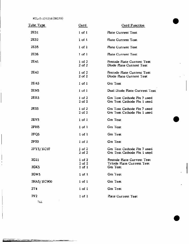
MIL-T-23125A(SHIW)
Tube Ty~
2E31
2E32
2E3S
2E36
2E41
Card Card Function
Plate Current Testlofl
Iofl Plate Current Test
lofl plate Current Test
lofl Plate Current Test
10f22of2
Pent&e Plate Current TestDiode Plate Current Test
2E42 Pentcde Plate Current TestDiode plate Current Test
10f2Zofz
2EAS
2EfWi
2ERS
Iofl Gm Test
Iofl Dual Diude Plate Current Test
Gm Test Cathnde Pin 7 usedGm Test Cathude Pin 1 used
lofz2of2
2ES5 lofz2of2
Gm Test Cathode Pin 7 usedGm Test Cathode Pin 1 used
2EV5
2FH5
2FQS
2FS5
2FY5/XC97
lofl Gm Test
lofl Gm Test
Gm Testlofl
lofl Gm lest
Gm ‘restCathodePin7 usedGm Test Cathode Pin 1 used
$Ofz20f2
2G21
2GK5
2GW5
2HAs/ xc 930
2T4
2V2
144
Pentode Plate Current TestTrio& Plate Current TestCm Test
Gm Test
Gm Test
lofz20f2lofl IIofl
lofl
Gm Testlofl
lofl Plate Current Test
a- ,—.-. = .- _ _.
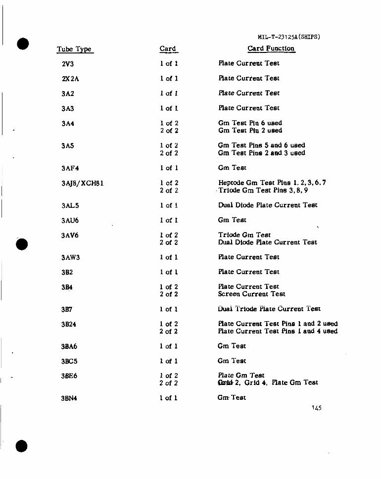
MIL-T-231 25A(SHIPS)
Card Fuoction
Plate Curreut Test
● Tube Type Card
lofl2V3
2X2A lofl Hate Current Teat
Flate Current Test3A2
Plate Current Test3A3 lofl
lofzZofz
lof2Zofz
lofl
Gm Teat Pin 6 usedGm Teat Pln 2 uned
Cm Teat Pins 5 and 6 usedGm Test Pin@2 and 3 used
Gm Test
3A4
3A5
3AF4
3AJ8/xcH81 lofzZofz
Heptode Gm Teat Pins 1.2,3.6,7Triode Gm Test Pins 3,8,9
Dual Diode Plate Current TeatI 3AL5 lofl
3AU6 Gm TestIofl
lofzZofz
lofl
lofl
Triode Gm TestDual Diode Plate Current Teat
Plate Current Test
3AV6
●3AW3
3B2
334
plate Current Test
lof2Zofz
plate Current Teat3creen Current Teat
Dual Triode Plate Current Test337
3024
lofl
lofz20f2
lofl
lofl
flate Current Teat Pins 1 and 2 usedplate Current Test Plna 1 and 4 used
Gm Teat3BA6
3BC5
3BE6
Gm Test
Plsre Gm TeetGrid 2, Grid 4, Plate Gm Teat
lofzZofz
lofl Gm Test1b?
3BN4
I—i—. —
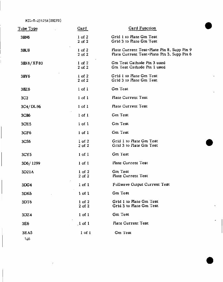
MIL-T-23125A(SHIPS)
Tube Type
3BN6
3BU8
38X6/XF80
3BY6
3KZ6
3C2
3C4/ DL96
3C86
3CE5
3CF6
3CS6
3CY5
306/ 1299
3D21A
3m4
3DK6
3DT6
3024
3E6
3EA5146
Card
lof220f2
10f220f2
10f220i2
lofz20f2
lofl
lofl
lofl
Iofl
lofl
Iofl
lofz20f2
lofl
Iofl
10f220f2
lofl
lofl
10f22of2
lofl
,lofl
lofl
Card Function
Grid 1 to Plate Gm TestGrid 3 to Plate Gm Test
Plate Current Test-Plate Pin 8, Supp Pin 9Plate Current Test-Plate Pin 3. Supp P1n6
Gm Test Cathode Pin 3 usedGm Test Cathode Pin 1 used
Grid 1 to Plate Gm TestGrid 3 to Plate Gm “rest
Gm Test
Plate Current Test
Plate Current Test
Cm Test
Cm Test
Gm Test
Grid 1 to Plate Cm TestGrid 3 to Plate Cm Test
Cm Test
Plate Current Test
Cm TestPlate Current Test
Fullwave Output Current Test
Cm Test
Grid 1 to Plate Cm TestGrid 3 to Plate Cm Test
Gm Test
Plate Current Test
Cm Test
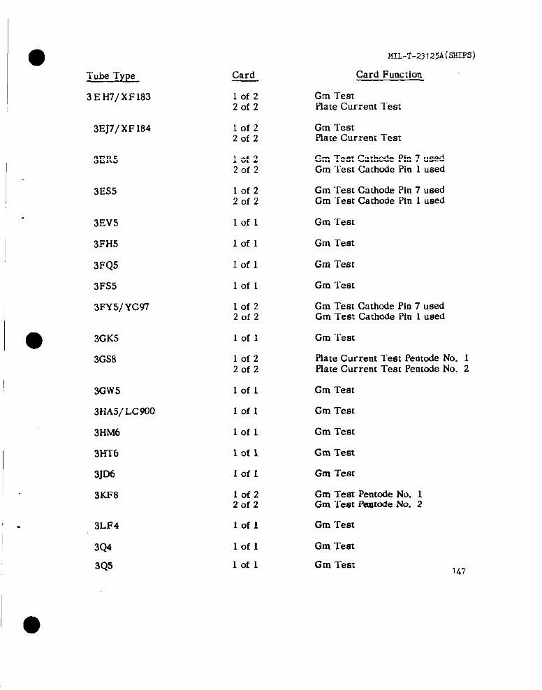
●Tube Type
3EH7/XF183
3EJ7/ XF 184
3ER5
3ES5
3EV5
3FH5
3FQ5
3FS5
3FY5/Yc97
● 3GK5
3GS8
3GW5
3HA5/ LC900
3HM6
3HT6
3JD6
3KF8
3LF4
3Q4
3Q5
Card
lofzZofz
lofzZofz
lofz20f2
lofzZofz
lofl
lofl
Iofl
lofl
lofzZofz
lofl
IofzZofz
lofl
lofl
lofl
lofl
Iofl
10f220f2
lofl
lofl
lofl
MIL-T-23125A(SHIPS)
Card Function
Gm TestPlate Current lest
Gm TestPlate Current Teat
Gm Test Cathode Pin 7 usedGm Test Cathode Pin 1 used
Gm Test Cathode Pin 7 usedGm “rest Cathode Pin 1 used
Gm Test
Gm Test
Gm Teet
Gm Test
Gm Test Cathnde Pin 7 usedGm Test Cathmie Pin 1 used
Gm Test
Plate Current Test Pentode No. 1Plate Current Test Penmde No. 2
Cm Test
Gm Test
Gm Test
Gm Test
Gm Test
Gm Test Pentode No. 1Gm Test Fmrtcde No. 2
Gm Test
Gm Test
Gm Test
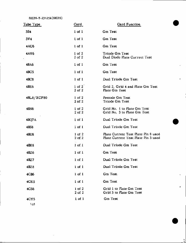
SHIPS-T-23125A(SltIpS)
Tube Type
3s4
3V4
4AU6
4AV6
Card
lofl
lofl
Card Function
Gm Test
Gm Test
lofl Cm Test
lofz20f2
Triude Gm TestDual Diode Piate Current Test
4BA6
4BC5
48C8
4BE6
lofl
lofl
Iofl
10f2’20f2
Gm ‘l-est
Gm Test
Dual “rriode Gm Test
Grid 2, Grid 4 and Plate Gm TestPlate Gm ‘lest
48L8/ XCF80 lofzZofz
Pent&e Gm TeatTriode Cm Test
Iofz20f2
Grid No. 1 to Plate Gm TestGrid No. 3 to Plate Gm Teat
4BQ7A
48S8
48U8
Dual Triode Gm Test●
Dual Trio& Gm Teat
lofl
lofl
10f2Zofz
Piate Current Test Hate Pin 8 usedPlate Current l-est Plate Pin 3 used
48X8
4i?Z6
4BZ7
4BZ8
4CJ36
4CE5
4CS6
Iofl Dual Triode Gm Teat
lofl Gm Test
lofl
lofl
Dual Triode Gm Test
Dual Triode Cm Test
lofl Gm Test
lofl Gm Test
Grid 1 to Plate Gm TestGrid 3 to Plate Gm Test
lof220f2
lofl Gm Test4CY51L9
● I
LI

● Tube T,LW
MIL-T-23125A(SFiIPS)
Card FunctionCard
4DE6
4DK6
4DT6
lofl Gm Test
lofl Gm Test
10f22of2
Grid 1 to Plate Gm TestGrid 3 to Plate Gm Test
4EH7/ YF 183 lofz20f2
Cm Test Cathode Pin 3 usedPlate Current Test Cathode Pin 1 used
4EJ7/ YF 184 Iofz20f2
Gm Test Cathode Pfn 3 usedPlate Current Test Cathode Pin 1 used
4ES8/XCC189
4EW6
4GK5
4GS8
lofl Dual Triode Gm Test
Iofl Gm Test
Gm Testlofl
10f220f2
Plate Current Test Plate No. 1Plate Current Test Plate No. 2
4GW.5
● 4GZ5
4HA5
Iofl Cm Test
lofl Gm Test
lofl Cm Test
Gm Test Plate No. 1Gm Test Plate No. 2
4HS8 10f220f2
4fiT6
4JD6
4KF8
lofl Gm Test
lofl Gm Test
lofzZofz
Cm Test Plate No. 1Gm Test Plate No. 2
5A6 lofz20f2
Plate Current TeatPlate Current Cut-Dff Test
I
I .lof220f2
Pentode Gm TestDicde Plate Current Test
5AM8
Penmde Gm TestTriode Cm Test
1L9
5AN8 10f220f2
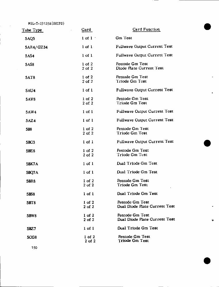
MIL-T-23125A(SHIPS)
Tube Type
I 5AQ5
Card
lofl’
Card Function
Gm Test
5AR4/Gz34
5AS4
5AS8
Fullwave Output Current Testlofl
Fuilwave Output Current Test
Pentode Gm TestDiode Piate Current Test
lofl
1 of. 220f2
5AT8 10f220f2
Pentode Gm TestTriode Cm Test
5AU4
5AV8
lofl Ftdlwave output Current Test
10f220f2
Pentode Cm TestTriode Gm Test
Fullwave output Current “lest5AW4
5AZ4
588
lofl
lofl Fullwave Output Current Test
10f220f2
Pentcde Gm TestTriode Gm “rest
Fullwave Output Current Test5BC3
5BE8
lofl
lofz2of2
Pentode Gm Test‘rriode Gm Test
Dual Trio& Gm Test
Dual Triode Gm Test
Penmde Gm TestTriode Gm Test
58K7A
58Q7A
SBR8
lofl
lofl
10f220f2
58S8
5BT8
lofl Dual Triode Gm Test
Penmde Gm TestDual Diode Flate Current Test
10f220f2
Pentode Gm TestDual Diode Plate Current Test
Dual Trio& Gm Test
5BW8 10f220f2
lofl5&?7
SG8
150
lofz20f2
Pentode Gm TestTriode Gm Test
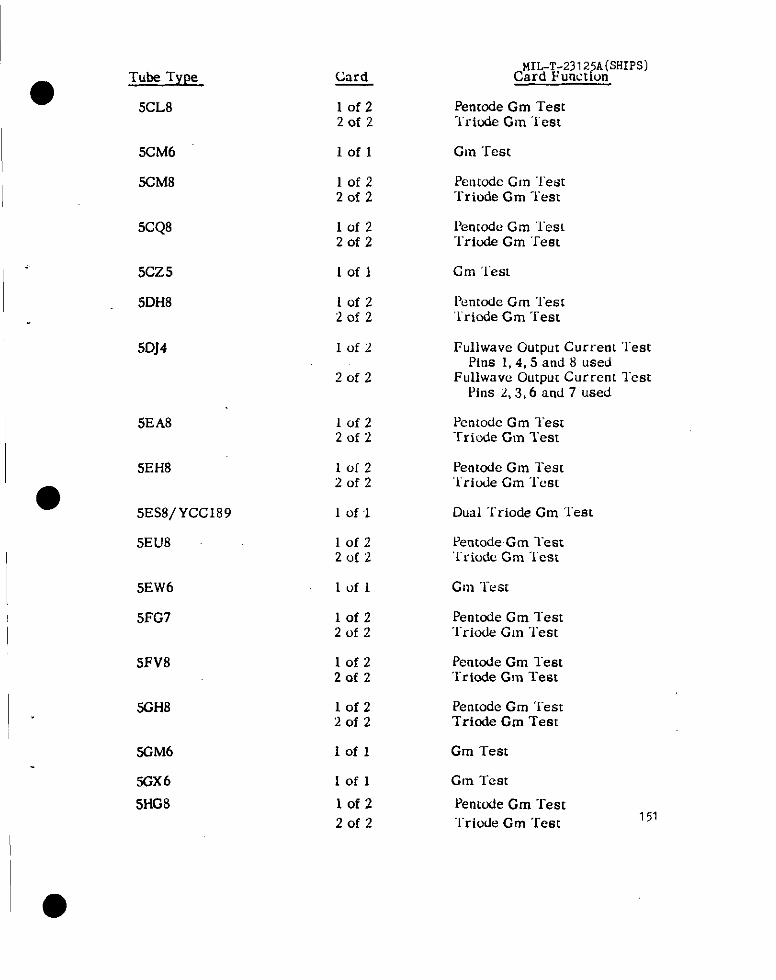
●Tube Type
5CL8
Card
10f220f2
MIL-T-2312:A(5HIPS)Card Functum
Penmde Gm Testli-ide G m Test
5CM6
SCM8
lofl Gnr “I_est
Pentode Gnr “lestl-riode Gm “lest
10f220f2
5CQ8 Iofz20f2
Pen[ode Gm ‘~esl‘Iriode Cm ‘Test
5CZ5
5DH8
Iofl Cm ‘lest
Iofz2of2
Pentode Gm ‘restTriode Cm Test
5DJ4 1of2 Fullwavc Output Currenl “TestPins 1, 4,5 and 8 used
Fullwavc Output Current lestPins 2,3,6 and 7 used
2rrf2
SEA8 Pentodc Gm Test“f’riwie Gnr ‘1’est
Irlfz2(.rf2
5EH8
5ES8/YCC189
10C220f2
Pentode Gm Test“Iricde Cm ‘lest
1 of 1 Dual Triode Gm ‘lest
5EU8 10f22clf2
Pentode Gm lest‘1’riodc Gm “lest
5EW6
5FG7
lofl
lofz2of2
Pentode Gm lest‘I”riode Gm Test
5FV8 lof220f2
Pentode Gm lestTriede Gm Test
Pentode Gm “I_estTriode Gm Test
Gm Test
Gm Test
Pentcde Gm Test“Iriode Gm Test 151
SGH8 Iofz20f2
5GM6
%X6
Iofl
Iofl
lof2
20f2
5HG8
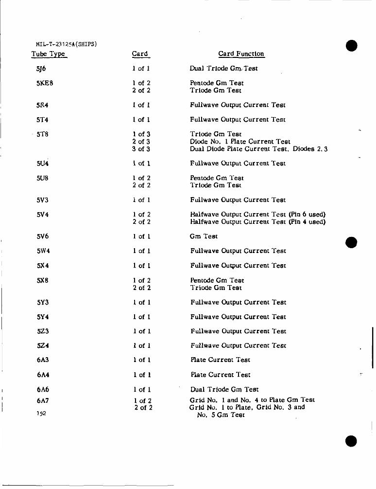
MIL-T-23I25A(sHIps)Tube Type Card
5J6 lofl
5KE8 lof22of2
5R4 Iofl
Card Function
Dual Triode Gm.Tesr
Penmde Gm TestTrio&e Gm Test
FulIwave Output Current Test
sr4 lofl Fullwave Output Current Test
5T8 10f320f33of3
Tricde Gm TestDide No. 1 Flare Current TestDual Diode Plate Current Test. Dicdes 2,3
5U4 lofl Fullwave Odtput Current Test
Pentode Gm TestTricde Gm Test
5U8 10f220f2
5V3 lofl Fullwave Output Current Test
Halfwave Output Current Test (Pin 6 used)Halfwave Output Current Test (Pin 4 used)
5V4 10f220f2
5V6 Iofl Gm Test
Fullwave Gutput Current Test5W4
5x4
5X8
lofl
lofl
10f220f2
Fullwave Output Current Test
Pentode Gm TeatTriode Gm Test
5Y3
5Y4
523
5Z4
6A3
6A4
Iofl FuUwave Output Current Test
Fullwave Output Current Testlofl
lofl
lofl
Fullwave Output Current Test
Fullwa weOutput Current Test
lofl Piate Current Test
Plate Current Testlofl
6A6 lofl Dual Trio& Cm Test
Grid No. 1 and No. 4 to Piate Gm TestGrid No. 1 to Plate, Grid No. 3 and
No. 5 Gm TestI 6A7
172
10f22of2
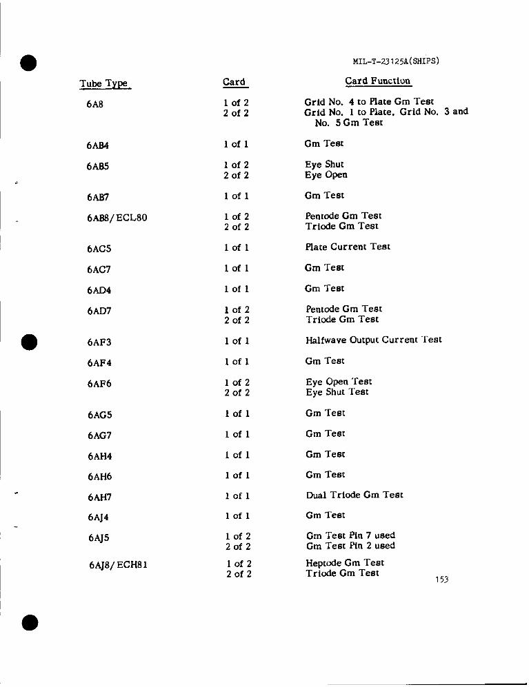
●Tube Type
6A8
6AB4
6A65
6AB7
6AB3/ECL80
6AC5
6AC7
6AD4
6AD7
● 6AF3
6AF4
6AF6
6AG5
6AG7
6AH4
6AH6
6AH7
6AJ4
6AJ5
6AJ8/EcH81
●
Card
lofz20f2
lofl
lofz2of2
lofl
lofz20f2
lofl
lofl
lofl
lofz20f2
lofl
lofl
lofzZofz
Iofl
lofl
Iofl
lofl
lofl
lofl
lofzZofz
10f2Zofz
MIL-T-23125A(SHI=)
Card Function
Grid No. 4 to Plate Gm TestGrid No. 1 to Plate, Grid No. 3 and
No. 5 Gm Test
Gm Test
Eye ShutEye Open
Gm Test
Pentode Gm TestTriode Gm Test
Plate Current Test
Gm Test
Gm Test
Pentode Gm TestTriode Gm Test
Halfwave Output Current “rest
Gm Test
Eye Open TestEye Shut ‘rest
Gm Test
Gm Test
Gm Test
Gm Test
Dusl Triode Gm Test
Gm Test
Gm Test pin 7 usedGm Test pin 2 used
Hepmde Gm TestTricde Gm Test
153
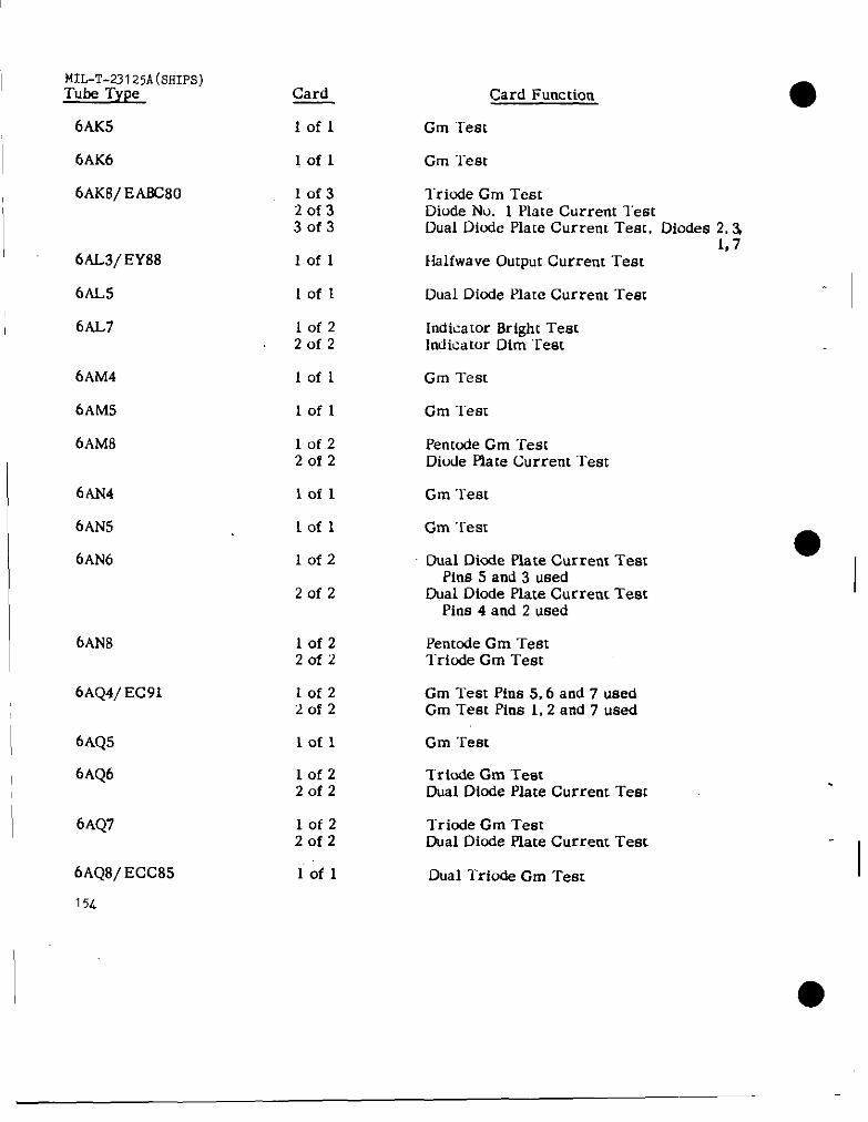
MIL-T-23125A(sHIps)Tube Type
6AK5
6AK6
6AK8/ EA6c80
6AL3/EY88
6tW5
6AL7
6AM4
6AM5
6AM8
6AN4
6AN5
6AN6
6AN8
6AQ4/ Ec91
6AQ5
6AQ6
6AQ7
6AQ8/ ECC85
15.L
Card
lofl
lofl
lof3‘20f330f3
lofl
lofl
lofzZofz
lofl
lofl
lof2Zofz
iofl
lofl
10f2
20f2
lof22of2
10f220f2
lofl
lofz20f2
lofzZofz
lofl
Card Function
Cm “Iest
Cm Test
l“riode Cm TestDiode No. 1 Plate Current TestDual Diode Plate Current Test, Diodes 2,3
1,7Halfwave Output Current ‘rest
Dual Diode Plate Current ‘rem
Indicator Bright TestIndicator Dim Test
Gm Test
Cm Teat
Penmde Cm ‘restDiode Plate Current Test
Cm ‘Test
Cm Test
Dual Dicde Plate Current TestPins 5 and 3 used
Dual Diode Plate Current TestPins 4 and 2 used
Penmde Cm Test“lriode Gm Test
Gm Teat Pins 5,6 and 7 usedCm Test Pins 1,2 and 7 used
Gm Test
Triode Gm TestDual Diode Plate Current Tem
Triode Cm TeatDual Diode Plate Current TesL
Dual Triode Cm Test
●I
I
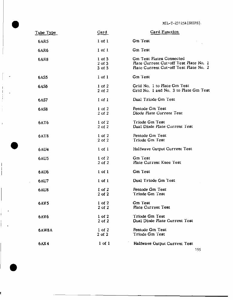
MIL-T-23125A(SHIPS)
Card
lofl
lofl
10f32of330f3
Card Function
Gm Test
Gm Test
Gm Test Plates ConnectedPlate Current Cut-off l“est Plate No. IPlate Current Cut-off Test Plate No. 2
Tube Type
6AR5
6AR6
6AR8
6AS5
6AS6
lofl Gm Test
Grid No. 1 to Plate Gm ‘l”estGrid No. 1 and No. 3 to Plate Gm Test
lofzZofz
Dual Triode Gm Test6AS7
6AS8
lofl
Penmde Gm TestDiode Plate Current Test
Iofz2of2
Triode Gm TestDual Diode Plate Current Test
6AT6 10f2Zofz
10f2Zofz
lofl
6AT8
● 6AU4
6AU5
Penmde Gm Test‘Irirrde Gm Test
HalfWaveOutput Current Test
lofz20f2
Gm TestPlsteCurrent Knee Test
6AU6
6AU7
6AU8
lofl Gm Test
Dual Triode Gm Testlofl
Iofz20f2
lofz20f2
Pentode Gm TestTriode Gm Test
6AV5 Gm TestPlate Current Test
6AV6 lofzZofz
Triode Gm TestDual Diode Plate Current Test
Pentude Gm TestTriode Gm Test
6AW8A lofz20f2
lofl Halfwave Output Current Test155
6AX4

MIL-T-23 I 25A(SHIPS)
Tube Type
6AX5
6AX7
6AX8
Card Function
Fullwave Output Current Teat
Card
lofl
loft Dual Triode Plate Current Test
Pentode Gm Testlriode Gm Test
10f220f2
6AY3
6AZ8
lofl Halfwave Output Current Test
lof22of2
Pentcde Gm TestTricde Cm Test
634
636
lofl Plate Current Test
Iofz2of2
Triode Gm Test
Dual Diode Plate Current TesL
Penmde Gm TestDual Dicde Plate Current Teat
6B7 lof220f2
10f220f2
lofl
Iofl
6B13 Penmde Gm TestDual Diode Plate Current Test
6BA3
6BA5
6BA6
6BA7
Halfwave Output Current Test
Gm Test
lofl Gm Test
IofzZofz
Grid No. 3 to Plate Cm TestGrid No. 1 to Plate Grid No. 2 and
No. 4 Gm Teat
6BA8 Penmde Gm TestTriode Cm Tem
Gm TestGm Test
10f220f2
6B.246BC5
6BC7
lofllofl
10f2Zofz
Diode Plate Current TestDual Diode Plate Current ‘i’eat
Dual Triode Gm Test6BC8
6BD4
6BD5
156
lofl
Iofl Cathode Current Test
Gm Tearplate Current Knee Test
lofzZofz
—.,.

● Tube Tyt)e
MIL-T-23125A(SHIPS)
Card Function
Cm Test
Triode Gm “remDual Dicde Plate Current Test
Card
lofl6BD6
6B07A/EtW8i 10f220f2
6BE6 10f22of2
Grid No. 3 to Piate Gm TestGrid No. 1 to Plste Grid No. 2 and
No. 4 Gm Test
Grid No. 1 to Plate Cm TestGrid No. 1 to Grids 2,3,4,5,6 &Piate Cm
Test
6BE7/ EQ80 lof220f2
Penmde Cm TestTriode Gm Test
Gm Teat
Trinde Gm Test~al Dicde Plate Current Test
6BE8 10f22of2
lofl6BF5
6BF6 10f22of2
6BF7W
6BF8
iofi Dual Triode Gm Test
lof320f330f3
Dual Diode Piate Current Test-Diodes 1,4Dual Diude Plate Current Test-Dimfes 2,5Dual Diode flare Current Test-Dicdes 3,6
Cm TestPlate Current Knee Test
Dual Triode Gm Test.
6BG6 lof220f2
6BG7
6BH3
6BH6
6BH8
Iofi
Iofl Halfwave Output Current Test
lofl Cm Teat
lofz20f2
Penmde Gm TestTriode Cm “rest
Gm Test6BJ5/N78
6BJ6
6BJ7
lofl
Iofl Gm Test
Piate Current Test pins 8 and 9 usedDual Dimie Piate Current Test
Triode Gm TestDual Dicde Plate Current Tesr
157
10f22of2
Iofz20f2
6BJ8
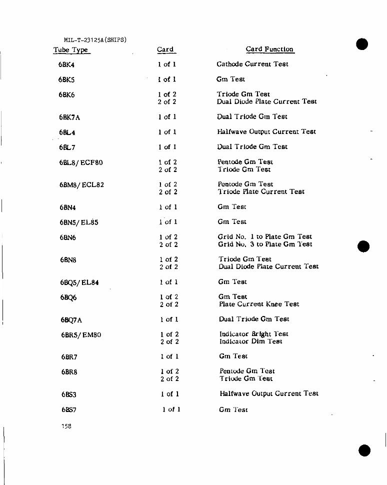
MIL-T-231 25A(SHIPS)
Tube TYF
68K4
6fiK5
6BK6
Card
lofl
Card Function
Cathode Current Test
lofl Gm Test
Triode Gm TestDual Diode Piate Current Test
Iofz2of2
6BK7A
6BL4
6i!L7
6BL8/ ECF80
lofl Dual Triode Gm Test
lofl Halfwave Output Current Test
Dual Triode Gm TestIofl
lofzZofz
Pentcde Cm TemTriode Gm Test
6BM8/ECL82 lof2Zofz
Penmde Gm Testlriode Plate Current Test
Gm Test
Gm Test
Grid No. 1 to Piate Gm TestGrid No. 3 to Plate Gm lest
6BN4
6BN5/EL85
6BN6
lofl
lofl
lofzZofz
6BN8 lofz20f2
Triode Gm TestDual Dicde Plate Current Test
Gm Test
Gm TestPiate Current Knee Test
Dual Triode Gm Test
6BQ5/EL84
6BQ6
lofl
10f220f2
6W7A
6BR5/ EM80
lofl
10f220f2
Indica[or Bright lestindicaior Dim Test
Gm Test
Pentode Cm TestTriode Gm Test
6EtR7
6BR8
lofl
lof2Zofz
68S3
6PS7
158
lofl Halfwave Output Current Test
IOfl Gm ‘J’esc
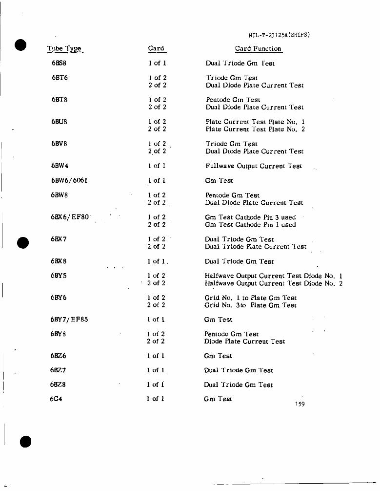
6BS8
6BT6
6rrr8
6BU8
68V8
6BW4
6Bw6/ 6061
6BW8
6Bx6/EF80”
● 6BX7
6BX8
6BY5
6BY6
6BY7/EF85
6BY8
6KZ6
6827
6BZ8
6C4
Card
Iofl
lofz2of2
10f2Zofz
10f220f2
lof22,0f 2
lofl
Iofl
lof22of2
lofzZofz”
Iofz’Zofz
lofl,
lofz2of2
lofz20f2
Iofl
lof220f2
of 1
of 1
of 1
of 1
MIL-T-23 125A(SHIPS)
Card Function
Dual “friode Gm lest
Trirxie Gm TestDual Diode Plate Current Test
Pentode Gm TestDual Diode Plate Current ‘1’esl
Plate Current Test Plate No. 1Plate Current ‘lest Plate No. 2
Triode Cm TestDual Diode Place Current Test
Fullwsve Output Current Test
Gm lest
Pentode Gm TestDual Diode Plate Current ‘l”est
Gm Test Cathode Pin 3 usedGm “I”estCathcde Pin I used
Dual Trio& Gm TestDu.=d“Iriode Plate Current l“est
Dual Triode Gm Test
Halfwave Output Current Test Diode No. 1Hslfwave Output Current ‘Test Dicde No. 2
Grid No. 1 to flate Gm TestGrid No. 3to Plate Gm Test
Gm Test
Pentode Gm TestDiode Plate Current Test
Gm Test
Dual l-riode Cm Test
Dual Triode Gm Test
Gm Test159
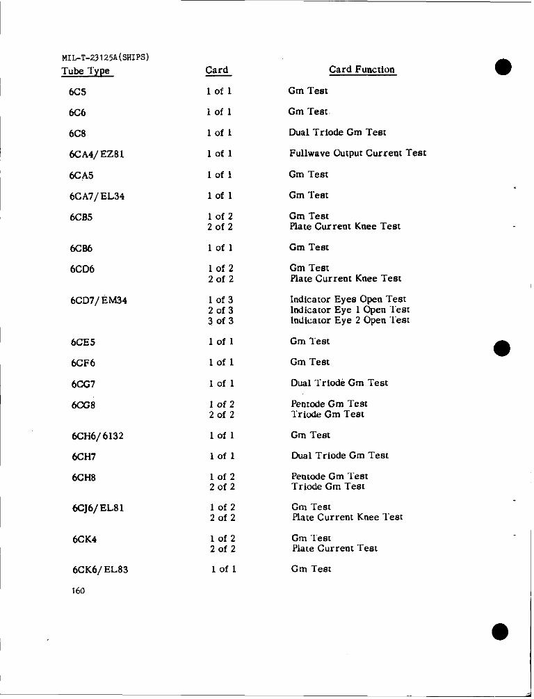
MIL-T-23125A(sHIps)
Tube Type
6CS
Card
lofl
Card Function
Cm Test
lofl Cm Test.
Dual Triode Cm Test
Fullwave Output Current Test
6C6
lofl
lofl
lofl
6C8
6CA4/EZ81
6CA5
6CA7/EL34
6CB5
Gm Test
lofl Gm Test
lofzZofz
Gm TestPlate Current Knee Test
lofl
10f2Zofz
10f320f33of3
Gm Test
Gm TestPiate Current Knee Test
6CB6
6CD6
6CD7/ EM34 Indicator Eyes Open TestIndicator Eye 1 Open “lestIndicator Eye 2 Open Test
6CE5
6CF6
6CG7
6CG8
lofl Gm Teat
lofl Gm Test
Dual Triocki Gm Testlofl
Iofz20f2
lofl
I Penmde Gm TestTriude Gm Test
6CH6/6132
6CH7
6CH8
Gm Test
Dual Triode Cm Testlofl
Penmde Gm TestTriode Gm Test
lofzZofz
lofz20f2
6cJ6/EL81 Gm TeatPiate Current Knee Test
Gm TestPlate Current “rest
Gm Test
6CK4 10f220f2
lofl6CK6/ EI-83
160
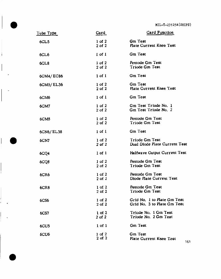
●Tube Type
6CL5
6CL6
6CL8
6Ctvf4/EC86
6cM5/ EL36
6CM6
6CM7
6CM8
6CN6/ EL38
● 6CN1
6CQ4
6CQ8
6CR6
6CR8
6CS6
6CS7
6CU5
6CU6
Card
lofzZofz
Iofl
lofzZofz
lofl
lofzZofz
lofl
lof220f2
lofzZofz
lofl
lofz2Qf2
Iofl
lofz20f2
lofz20f2
lof2Zofz
lofzZofz
lofz20f2
lofl
lofz20f2
MIL-T-23125A(SIIIPS)
Card Function
Gm TestPlate Current Knee Test
Gm Test
Penmde Gm TestTriode Gm Test
Gm Test
Gm TestPlate Current Knee Test
Gm Test
Gm Test Trlode No. 1Gm Test Triorie No. 2
Pentcde Gm TeatTriode Gm Test
Gm Test
“~ricde Gm TestDual Dbde Place Current Test
Haifwave Output Current Test
Pentode Gm TestTricde Gm Test
Pentode Gm TestDiode Plate Current Test
Pentode Gm TeatTriode Gm Test
Grid No. 1 to PIate Gm TestGrid No. 3 to Plate Gm Test
Triode No. 1 Gm TestTrlode No. 2 Gm Tes[
Gm Test
Gm ‘restPlste Current Knee Teat
161
—

MII,-~-23125A(SHIPS)
Tube Ty~
6CU8 “
6CW4
6CW5/ EL86
6CW7/ECC84 ‘
6CX8
6CY5 ,
6CY7
6CZ5
6D4
6D6
6DA4!
6DA5/EM81
6DA6/ EF89
6DA7
6DB5
6DB6
I6DC6
6Dc8/ EBF89
162
Card
lof220f2
Iofl
lofl
Iofl
10f220f2
Iofl
10f320f330f3
lofl
10f320f33of3
lofl
lofl
lof220f2
Iofl
10f320f330f3
10f22of2
10f220f2
Iofl
10f22 0f2
I ,),z,.,
~ ,;:,, $
.<\ -..<’,
I
Card Function
Pentode Gm TestTriode Gm Test
Gm Tes[
Gm Test
Dual Triode Gm Test
Pentode Gm TestTriode Gm Test ‘
Gm Test
Triode No. 1 Gm Testl-riode No. 2 Gm lestTricde No. 2 Plate Current Test
Gm Test
Cathode Current TestPla[e to Cathode Voltage TestFlate Current Cut-off Test
Gm Test
HslfwaveGutputCurrentTeat
Indicator Bright TestIndicator Dim Test
Gm Test
Triode No. 1 Gm Test“Iriode No. 2 Gm “lestlriode No. 2 Plate Current .Test
Gm Test Pins 1,6,7 and 9 usedGm “lest Pins 1,2,3 and 9 used
Grid 1 to Plate Gm TeatGrid 3 to Plate Gm “rest
Gm “rest
Penmde Gm Test...Dual Diode Plate Current Test
i.
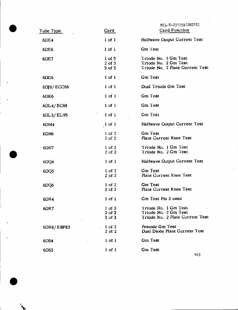
I
Tube Type
6DE4
6DE6
6DE7
6DG6
6DJ8/ ECC88
6DK6
6DL4/ EC88
6DL5/ EL95
6DM4
6DN6
6DN7
6DQ4
6DQ5
6DQ6
6DR4
6DR7
6DR8/ EBF83
6DS4
6DS5
Card
Iofl
lofl
lof32of33of3
lofl
lofl
lofl
lofl
lofl
,Iofl
10f220f2
10f220f2
lofl
lof220f2
10f22of2
lofl
10f320f33of3
lofz20f2
lofl
lofl
MIL-T-23125A(SHIFS)Card Function
Halfwave Output Current lest
Cm ‘lest
“[r{ode No. 1 Cm TestTrlode No. 2 Cm TestTriode No. 2 Plate Current Test
Gm lest
Dual Triocie Cm Test
Cm “lest
Cm lest
Gm ‘1’est
Halfwave Output Current Test
Cm TestPlate Current Knee Test
lriode No. 1 Cm TestTriode No. 2 Cm ‘lest
Halfwave Output Current Test
Cm TestPlate Current Knee Test
Gm TestPlate Current Knee Test
Cm Test Pin 5 used
Triode No, 1 Cm TeatTriode No. 2 Cm Test‘Iriode No. 2 Plate Current Test
Pentode Cm TestDual Diode Plate Current Test
Cm Test
Cm Test163
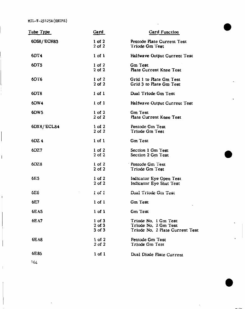
MIL-T-23125A(SflIPS)
Tube Type
6DS8/ ECH83
6DT4
6DT5
6DT6
6DT8
6DW4
6DW5
6Dx8/ ECL84
6DZ 4
6DZ7
6DZ8
6E5
6E6
6E7
6EAS
6EA?
6EA8
6EB5
1(4
Card Card Function
lof2 Petttode Plate Current Test2of2 Triode Cm Test
lofl HaIfwave Output Current Test
lofz Gm Test2of2 Plate Current Knee Test
10f2 Grid 1 to Plate Gm Test2of2 Grid 3 to place Cm Test
lofl Dual Triode Gm Test
Iofl Halfwave Output Current Test
10f2 Gm Test2of2 Rate Current Knee Test
10f2 Pentode Gm Test20f2 Triode Cm Test
lofl Gm Test
lof2 Section 1 Gm Teat2of2 Section 2 Gm Teat
10f2 Pentode Cm “1’est2of2 Triode Cm Test
lof2 Indicator Eye Open Test2of2 Indicator Eye Shut Test
Iofl Dual Triode Gm Test
Iofl Gm Test
lofl Gm Test
10f3 Triode No. 1 Cm Test2of3 Trbde No. 2 Cm Test3of3 Triode No. 2 Piate Current Test
lofz Pentode Cm TestZofz Triode Gm Test
lofl Dual Diode Plate Current
.—.
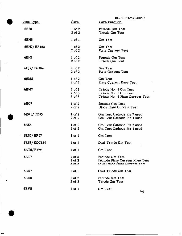
● Tube TYP
6E88
6EH5
6EH7/EF183
6EH8
6EJ7/EF184
6EM5
bEM7
6EQ7
●6ER5/EC95
6ES5
6Es6/EF97
6ES8/ ECC189
6ET6/EF98
6E’T7
6EU7
6EU8
Card
lofzZofz
Iofl
IofzZofz
IofzZofz
lofzZofz
lof220f2
1 of 320f330f3
lof220f2
lofzZofz
IofzZofz
lofl
lofl
lofl
lof320f330f3
lofl
lof2Zofz
lofl
MIL-T-23125A(SHIPS)Card Function
Penmde Gm TestTricde Gm Test
Gm Test
Cm TestPlate Current Test
Penmde Gm TestTriode Gm Test
Gm TestPlate Current Test
Gm TestPlate Current Knee Test
Triode No. 1 Cm TestTrinde No. 2 Gm TestTriode No. 2 Plate Current Test
Penmde Gm TestDicde Plate Current “lest
Cm Test Cathnde Pin 7 usedGm Test Cathcde Pin 1 used
Gm Test Cathcde Pin 7 usedGm Test Cathode Pin 1 used
Gm Test
Dual Triode Gm Test
Gm Test
PentcxleGm TestPentOde Plate Current Knee TestGual Dlnde Plate Current Test
Dual Triode Gm Test
Pentcde Gm TestTriode Gm Test
6EV5 Gm Test165
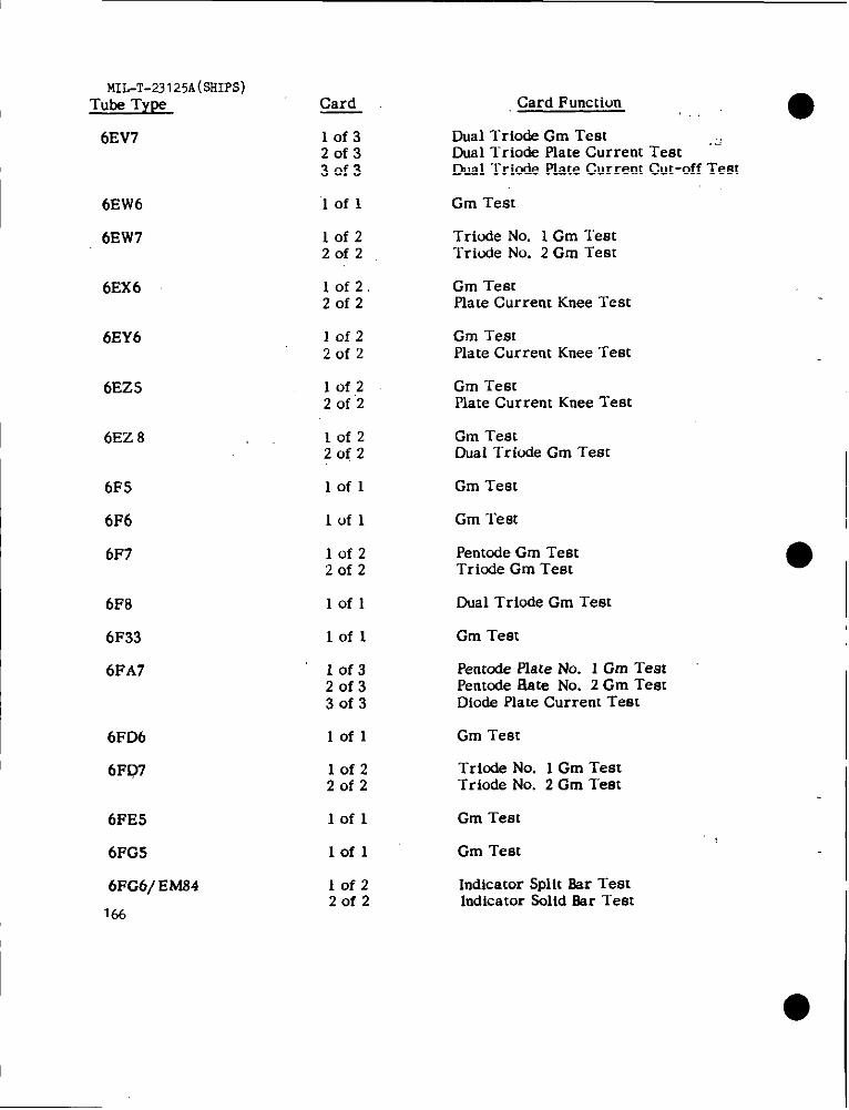
MIL-T-23125A(SHIPS)Tube Type Card
6EV7 10f320f330f3
6EW6
6EW7
6EX6
6EY6
6EZ5
6EZ 8
6F5
6F6
6F7
6F8
6F33
6FA7
6FD6
6FD7
6FE5
6FG5
6FG6/ EM84
166
lofl
10f220f2
10f2.20f2
lofz20f2
1 of ,220f2
Iofz20f2
lofl
lofl
lof22of2
lofl
lofl
lof320f330f3
lofl
10f220f2
lofl
lofl
lofz20f2
Card Function,.. . ●
Dual Triode Cm TestDual Triode Piate Current Test “’””Dual Triode Piate Current Cut-off Test
Cm Test
Triode No. 1 Cm TestTriude No. 2 Gm Test
Cm TestPiate Current Knee Test
Cm TestPlate Current Knee Test
Cm TestPlate Current Knee Test
Gm TestDual Triode Gm Test
Cm Teat
Gm Test
Pentode Cm TestTriurie Cm Test
Dual Trinde Cm Test
Gm Test
Pentode Plate No. 1 Gm TestPentnde Rate No. 2 Cm TestDiode Plate Current Test
Cm Test
Triode No. 1 Cm Test“Irinde No. 2 Gm Test
Cm Test
Gm Test
Indicator Split Ear TestIndicator Snlid Bar Test
● I

● Tube Type
6k?G7
6FH5
6FH6
6FH8
6FM8
6FQ5 ;
6FQ7
6FS5
6FV6
●6FV8
6FW5 ,
6FW8
6FY5/Ec97
6FY8 ‘
6GS
~“6 ‘
6GC5
6GC6
Card
Iofz20f2... ,
lofl
lof2Zofz
10f4,20f430f440f4
lofzZofz,., .
,: .,,.Iofl
,., ,,lofi
.;,
.’lofl
.. Iofl$,, .
lof22,0f 2,.
lofz,: .’ . ‘:’20f 2
lofl
Iofz2of2
iofzZofz
i ‘of2.,:Zofz
lofl
lofzZofz
IofzZofz
MIL-T-231 25A(SHIPS).
Card Function
PentOde Gm TestTriode Gm TesL
Gm Test
Gm TestPlate Current Knee Test
Tetrode Plate No. lGm Test‘Tetrode Plate No. 2Gm ‘restTetrcde Plate No. 3 Cm TestTriode Gm Test ,,.
‘I”riodeCm ‘Test13Ml Diode Plate Current Test.,
Cm Test
Dual Triode Cm Tt?m ‘“
Cm Test .,
‘Gm Test,,!<
Pentode Gm Teat,Triode Gm Test ,,,
Cm l“estPlate Current Knee Test “<
Dual Triode Cm Test : ,
Gm Test Cathode Pin 7 usedi:.Cm Test Cathode Pin 1 used
,; .:!Penmde Cm Testl-riode Cm Test
Indicator Eye Open TestIndicator Eye Closed Test
Gm Test
Cm TeatPlate Current Test
Gm TestPlate Current Knee Test ‘
167
—
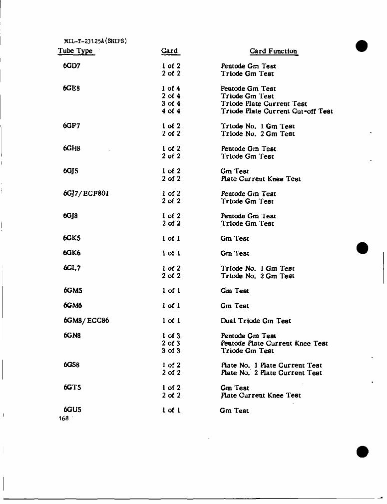
MIL-T-23125A(sSIPS)Tube T’YW
fiD7
Card
lofz20f2
Card Function
Peumde Gm TestTr@de Gm Test
Pemode Gm TeatTriode Gm ‘lestTriode Piate Current TestTriode Plate Current Cut-off Test
Triode No. 1 Gm TeatTriode No. 2 Gm Teat
Pentode Cm TestTr{ode Gm Test
lof420f43of44of4
lofz2of2
6GF7
GH8 lofzZclfz
6GJS lof22of2
Gm TestPlate Current Knee Teat
10f2Zofz
10f2Zofz
Pentode Gm TestTrfode Gm Test
6GJ8 PentOdeGm TestTriode Gm Test
Gm Test~K5
6GK6
6GL7
lofl
lofl Gm Teat
IofzZofz
lofl
Iofl
Tricde No. 1 Gm TestTriode No. 2 Gm Test I
6GMS
6GM66GMs/ECC86
6GN8
Cm Test
Gm Test
Dual Triode Cm Test
I
lofl
10f32of330f3
IofzZofz
Pentode Gm TestPentOdePlate Current Knea TestTricde Gm Test
6GS8 Plate No. 1 Elate Current Teatplate No. 2 Flate Current Teat
Gm TestWte Current Knee Test
(K3TS lof22of2
6GU5168
lofl Gm Test

MIL-T-23125A(sHIPs)●
Tube Type Card Function
Dual Triode Cm l-em
Card
lofl
10f320f33of3
lofl
6GU3
6Gv8/ ECL85 PentOdeGm TestPenmde Plate Current Knee l-emTrinde Gm ‘rest
6GW5
6GW6
Gm Test
IofzZofz
Gm TestPlate Current Knee Test
6Gw8/ ECL86 Penmde Gm TestTriode Gm Test
lofz20f2
Iofl
lofl
lof32of330f3
6Gx6
6GY6
6GY8
Gm Test
Gm Test
Triode No. 1 Plate Current TeatTrinde No. 2 Gm TestTriode No. 3 Cm Test
6H6
6HA5/ EC900
6H86
6HC8
lofl Dfude Plate Current Test
Gm Testlofl
lofzZofz
10f320f330f3
Gm TestPlate Current Knee Test
PentOdeGm TestPentnde Plate Current Knee TestTrio& Gm Teat
6HF8
6HG8/ ECF86
IofzZofz
Pentode Gm TestTrinde Gm Test
lofzZofz
Pentode Gm TestTrinde Gm Test
6HJ8
6HL8
lofzZofz
lofzZofz
Pemode Gm TestDiode Plate Current “1’est
Pentode Gm TestTrinde Gm Test
6HM6 lofl Gm Test169
6-

MIL-T-nI25A(SHIPs)
Tube Type
6HR6 ‘ :’
6HS6
6HS8, ...
6HT6
6HU6/ EM87
6HU8/ELL80
6HW8
6HZ6
6HZ8
6J4
6J5
6J6, .
6J7
6J8
6JA8
6J86
6JB8
170
Card
lofl
lofl
1 0f,220f2
lofl
10f22of2
10f22of2
10f320f330f3
Iofl
lof32of33 of 3,
1 of 3,20f330f3
lofl
lofl
lofl
lofz2of2
1 of 2’20f2
1 Of.220f2
1 0f,220f2
Card Function
Gm Test
Gm Test
plate No. 1 Gm TestPlate No. 2 Gm Test
Gm Test
Indicator Split Bar TestIndicator Solid Bar Test
Pentode NCI. 1 Gm TestPentode No. 2 Gm Test
Pentcde Gm TestPlate Current Cur-off Test (Plate No. 2)Plate Current Cut-off Test (Plate .No. 1)
Gm Test
Pentode Gm TestPentode Plate Current Knee TestTriode Cm Test
Gm Test Pin 6 usedGm “rest Pin 5 usedGm Test Pfn 1 used
Gm “rest
Dual TrMe Gm Test
Gm Test
Pentode Gm TestTrfode Gm Test
Tetrode Gm TestTriode Gm Test
Gm TestPlate Current Knee Test
Pentcde Gm TestTricde Gm Test

I
Tube TYW Card
6JC8 10f2Zofz
6JD6 lofl
6jE8 10f220f2
6JF8 10f32of330f3
6JH6 Iofl
6JH8 10f32of330f3
6JK8
6JT8
a6JU8
lofzZofz
lofzZofz
Iofz20f2
6JV8 10f220f2
6JX8/ ECH84 10f220f2
6K5 lofl
6K6 Iofl.,
6K7 lofl
6K8 lofzZofz
6KA8 lof220f2
MIL-T-23I2jA(5HIPs)
Card Function
Pentode Gm Test‘Iriode Gm Test
Gm lest
Pentode Gm ‘TestTrio& Gm Test
Pentnde Gm TestPentode Plate Current Knee TestDiode Halfwave Dutput Current Test
Gm Test
Pentode Gm ‘l-emPlate Current cur-off “rem (Plate No. 1)Plate Current Cut-off Test (Plate No. 2)
‘I”riodeNo. 1 Gm TestTriode No. 2 Gm ‘Test
Pent&e Gm “lest‘rriude Cm ‘Iest
Dual Diude Plate Current ‘rest (Diodes 1,3)Dual Diode Plate Current ‘Test (Dicdes 2,4)
Pentcde Gm Testl“riode Gm Test
Pentode Plate Current TestTriode Cm Test
Gm Test
Gm Test
Gm Test
Grid No. 3 to Plate Gm “restTriwle Gm ‘I”est
Pentode Gm Testlriude Gm Test
6KD8 iofz Pentode Gm ‘l-est2of2 “rriode Gm ‘Test 171
,.,’ ;/,
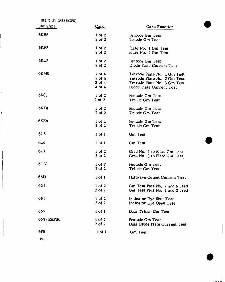
MIL-T.23125A(sHIPs)Tube Type
6KE8
Card
lof220f2
lof220f2
Card Function
Pemcde Gm Teat“TriodeGm Test
plate No. 1 Cm TestPlate No. 2 Cm Test
6KF8
6KL8 10f22of2
Penmde Gm TestDhXiePlate Current Test
6KM8 10f420f43of440f4
Tetrode Piate No. 1cm rest‘letrorie Plate No. 2 Gm ‘Test‘Fe[rode Plate No. 3 Gm ‘EestDiode Plate Current ‘ICSC
6KS8 lof220f2
10f220f2
Pentode Gm Test“Iriude Gm Test
6KT8 Peritode Gm Testlriwde Gm ‘lest
6KZ8 10f220f2
Penwr.ieCm ‘rest‘i’riude Cm “lest
6LS
6L6
6L7
lofl Gm Tea
Iofl
10f220f2
lofz20f2
Cm Test
Grid No. 1 to Plate Cm “restGrid No. 3 to Plate Gm ‘rest
Penmdc Gm ‘Iest“Iriude Gm “rest
6L88
6A43
6N4
lofl f-ialfwaveOutput Current Tem
10f2Zofz
Gm Test Pins No. 7 and 6 usedGm Test Pins No. 1 and 2 used
6N5 10f22of2
lofl
Indicator Eye Shut TestIndicator Eye Open Test
Dual Triode Cm ‘rest6N7
6Ns/E8F80
6P5
172
10f22of2
lofl
Pentode Cm TestDual Diode plate Current Test
Cm Test
... . .
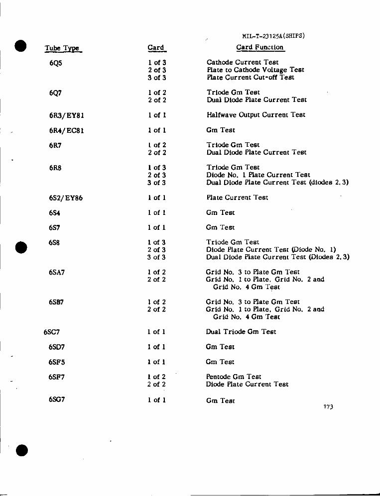
MIL-T-23125A(SHIPS)
Card Function
Cathcde Current TeatPlate to Cathode Voltage TestPke Current Cut-off Test
Trinde Cm TestDual Diode Plate Current Test
Card
lof320f33of3
6Q5
6Q7 lofzZofz
6R3/EY81
6R4/ EC81
6R7
lofl fialfwave Cutput Current Test
lofl Gm Teat
Triade Gm TestDual Diode Piate Current Test
Tricde Gm TeatDiode No. 1 Plate Current TestDual Diode Plate Current Test (diodes 2.3)
lofzZofz
6R8 lof32of330f3
6S2/EY86
6S4
6S7
Iofl Plate Current Test
Cm Testlofl
lofl Gm Test
● 6s8 lof32of330f3
Triode Gm TestDiode Plate Current Test (Diode No. 1)Dual Diode Plate Current Test (Dicdes 2,3)
Grid No. 3 to Plate Gm TestGrid No. 1 to Plate. Grid No. 2 and
Grid No. 4 Gm Test
6SA7 lofz20f2
6SB7 lofzZofz
Grid No. 3 to Plate Gm TestGrid No. 1 to Plate, Grid No. 2 and
Grid No, 4 Cm Test
Dual Triode Gm Teat6SC7
6SD7
6SF5
6SF7
6S437
lofl
Gm Teatlofl
lofl
lofz2of2
Gm Test
PentOdeCm TestDiode Plate Current Test
lofl Gm Tem173
1‘*
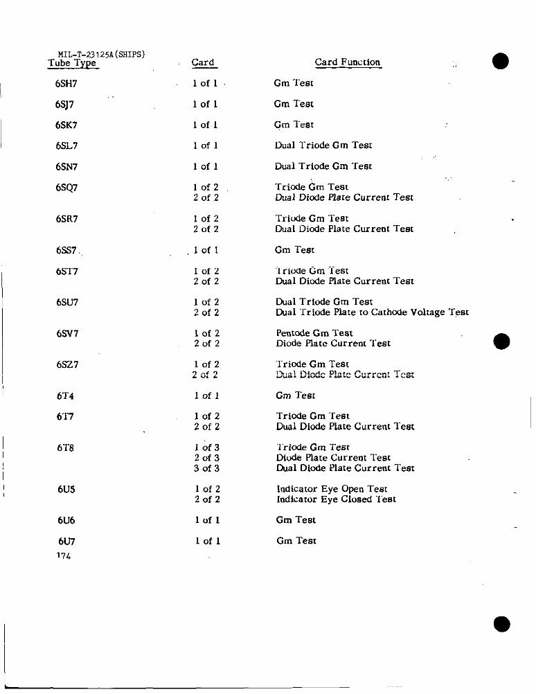
MIL-T-23I25A(5HIP5)Tube Type
! 6SH7I ,.
6SJ7
6SK7
6SL7
6SN7
6SQ7
6SR7
6SS7
6ST7
6SU7
6SV7
6SZ7
6T4
6T7
I 6T8
6U5
6U6
6U717L
Card
lofl
lofl
lofl
lofl
lofl
10f220f2
10f22r)f2
lofl
lofzZofz
10f220f2
lofz20f2
lofz20f2
lofl
10f220f2
10f320f330f3
10f22of2
lofl
lofl
., ●Card Function
Cm Test
Gm Test
Gm Test
Dual Triode Gm Test
Dual Triode Gm Test
Tricde Gm TestDual Diode Place Current Test
Tricde Gm TestDual Diode Plate Current Test
Gm Test
lriode Gm TestDual Diode Piate Current Test
Dual Triode Gm TestDual Triode Plate to Cathnde Voltage Test
Pen[ode Gm TestDiode Plate Current Test
Tride Gm TestDual Dinde Piate Current Test
Gm Test
Trinde Gm TestDUS1Diode Piate Current Test
‘1’riodeGm TestDiode Plate Current TestDual Diode Plate Current Test
Indicator Eye Open TestIndicator Eye Closed “I”est
Gm Test
Gm Test
I

● Tube TyPe CardMIL-T-23125A(%lIW)
Card Function
6U8 lof22of2
Pentode Cm TestTriode Cm l-CM <
6V3 lofl Halfwave Output Current ‘rest
6V4/ EZ80 Iofl Fullw.ave Output Current Test
6V6 lofl Gm Test
6V7 10f220f2
Tricde Gm TestDual Diode Plate Current lest
6V8 10f32of33of3
6w4 .,: Iofl,,
6W6 lofl
Triode Gm TeatDiode Plate Current Test (Oiode No. 1)Dual Diude Plate Current Test (Diodes 2,3)
Hslfwave Output Current Test
Gm Test
6W7 lofl.,
I 6X4 Iofl
Cm Test
Rullwave Output Current Test
Ftdlwave Output Current “lest
●6X5
6x6
lofl
Indicator Eye Open TeatIndicator Eye Closed “I_est
Pentode Cm TestTriode Gm ‘lest
‘10f2Zofz
6x8 “ Iofz20f2,..
6Y6 l’ofl Gm Test
6Y7 Iofl Dual Triode Gm Test ‘. ~ :
6Z4 Iofl FuUwave Output Current Test
Fullwave output Current Test6Z5/ 12Z5 lofl,!,
6ZY5 lofl Fullwave Otrtput Current Teat
7A4 lofl Cm Test
7A5 lofl. Gm Test
7A6 . Iofl Dual Diode Plate Current Teat175
L. -.
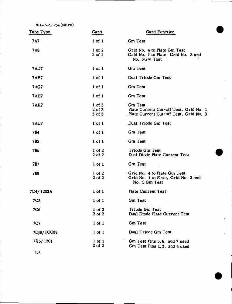
MIL-T-23125A(SHIPS)
Tube Type Card Card Function
Gm Test7A7 lofl
7A8 10f220f2
Grid No. 4 m Plate Gm “restGrid No. 1 to Flate, Grid No. 3 and
No. 5Gm Test
7AD7
7AF7
7AG7
7At17
7AK7
Iofl Gm Test
Iofl Dual Triode Cm Test
lofl Cm Teat
Iofl Gm Test
lof320f330f3
Gm Testplate Current Cut-off Test, Grid No. 1plate Current Cut-off “rest, Grid No. 3
Dual Triode Cm Test7Ai17
764
735
lofl
Iofl Cm Test
lofl Cm Teat
lof220f2
Triode Gm TestDual Diode Plate Current Test
73’7
738
Iofl Gm Test
Grid No. 4 to Plate Cm TestGrid No. 1 to Plate, Grid No. 3 and
No. 5 Cm Test
10f220f2
7C4/ 1203A
7C5
7C6
Iofl Plate Current Teat
lofl Gm Test
10f220f2
Triode Gm TestDual Dfnde Plate Current Teat
Iofl Gm Test7C7
7DJ8/ FCC88
7E5/ 1201
lofl Dual Trinde Cm Test
lof22of2
Gm Test Pins 5,6, and 7 usedGm Test Pins 1,3, and 4 used
176
●
L
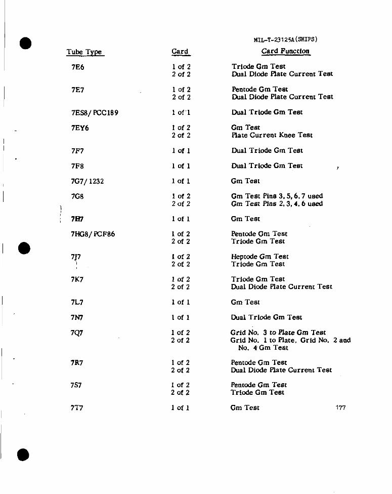
Tube Type
7E6
7E7
7Es3/ FCC189
7EY6
7F7
7P8
7G7/ 1232
7G8
i 7f37
7HG8/ FCF86
7K7
7L7
7N7
7Q7
7R7
7s7
717
Card
lofz2of2
IofzZofz
1 of”;
Iof220f2
lofl
lofl
lofl
IofzZofz
lofl
lofzZofz
IofzZofz
lofzZofz
lofl
lofl
IofzZofz
Iofz20f2
10f22of2
lofl
MU-T-23125A(SHIPS)
Card FuuccIon
Triode Cm TestDual Dfode Plate Current Teat
Pentode Gm TestCual Diode Plate Current Test
Dual Triode Gm Teat
Gm TestPlate Current Knee Test
Dual Triode Gm Test
Dual Triode Gm Test r
Gm Test
Gm Test Pins 3,5,6,7 usedGm Test pins 2,3,4,6 used
Gm Test
Penmde Gm TeatTriode Gm Teat
Iieptcde Gm TestTriode Gm Test
Triode Gm TestDual Diode Plate Current Test
Gm Test
Dual Triode Cm Test
Grid No. 3 to Plate Gm TeatGrid No. 1 to Plate, Grid No. 2 and
No. 4 Gm Test
PentOdeGm TestCad Diode Plate Current Test
Pentode Gm TestTricde Gm Test
Gm Test 177
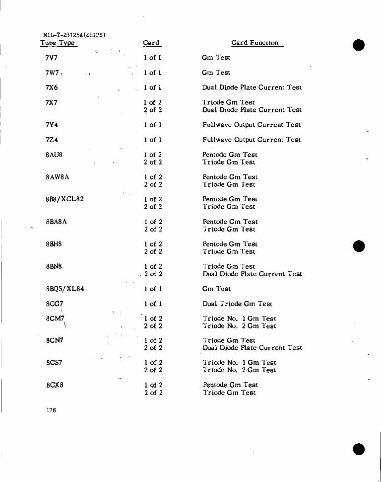
MIL-T-23125A(SHIPS)Tube Type
7V7
7W71 1,
7X6
7x7
7Y4
724
8AU8
8AW8A
888/ XCL82
I 8BA8A.
8BH8
8BN8
8BQ5/XL84
8CG7
8cMi
8CN7
,.8CS7
.!
8CX8
178
Card
lofl
lofl
lofl
lofzZofz
lofl
lofl
lof22of2
lofzZofz
lofzZofz
IofzZofz
IofzZofz
lofzZofz
lofl
lofl
lofzZofz
IofzZofz
lofzZofz
lof2Zofz
Card Function
Cm Test
Gm Test
Dual Diode Plate Current Test
Triode Gm TestDual Diode Plate Currem l-est
Fullwave Output Current Test
Ftdlwave Gutput Current Test
Pentmfc Gm TestT’rinde Gm Test
Penccde Gm Test‘I-ride Gm Test
Pent&e Gm Test‘rriode Gm Test
Pentode Gm Testlriode Gm “rest
Pentode Gm TestTriude Gm ‘rest
Triode Gm TestDual Diode Plate Current Test
Gm Test
Dual Triode Gm Test
Triode No. 1 Gm TestTriode No. 2 Gm lest
Triode Gm TestDual Diode Plate Current Test
Triode No. 1 Gm Testl’riode No. 2 Cm Test
.Pentode Cm TestTriode Gm Test
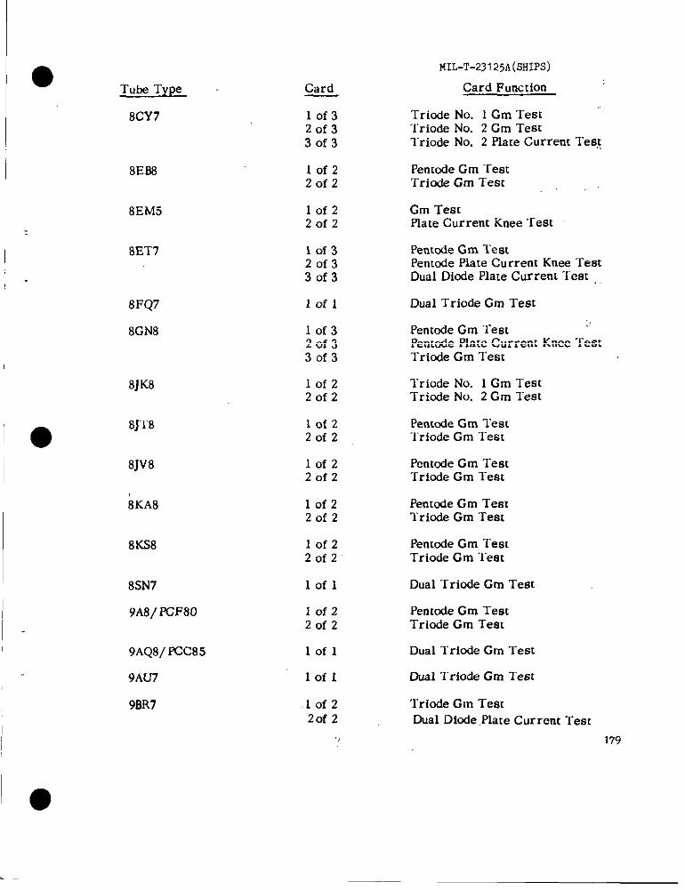
I 8CY7
8E88
8EM5
8ET7
8FQ7
8GN8
8JK8
8J18
8jv8
EKA8
8KS8
8SN7
9A8/ PCF80
9AQ8/ PCC85
9AU7
9BR7
Card
lof320f330f3
lofz2of2
lofz2of2
10f320f330f3
10f I
lof320f330f3
10f220f2
10f220f2
10f2Zofz
lofz20f2
lofzZofz
lofl
lof22of2
lofl
Iofl
,lofzZofz
141L-T-23125A(sHIps)
Card Function
Tricde No. 1 Gm TestTriode No. 2 Cm Teatlriode No. 2 Plate Current Test
Pentode Cm TestTrio& Gm Test
Gm TestPlate Current Knee Test
Penmde Gm TestPenmde Plate Current Knee TestDual Diode Plate Current “f’est .,
Dual Triode Gm Test
Pentcde Gm TestPentnde Plate Current Knee TestTricde Gm Test
Triude No. 1 Gm TestTricde No. 2 Gm Test
Pentcde Gm Test‘Iriode Gm l“est
Penmrie Gm TeatTricde Cm “rest
Pentcde Gm TestTriode Gm Test
PentOdeGm TestTriode Gm ‘lest
Dual “Iriode Gm Test
PentOdeGm TestTriode Gm Teat
Dual Triode Gm Test
Dual Triode Gm Test
Triode Gm TestDual Diude .Plate Current Test
179
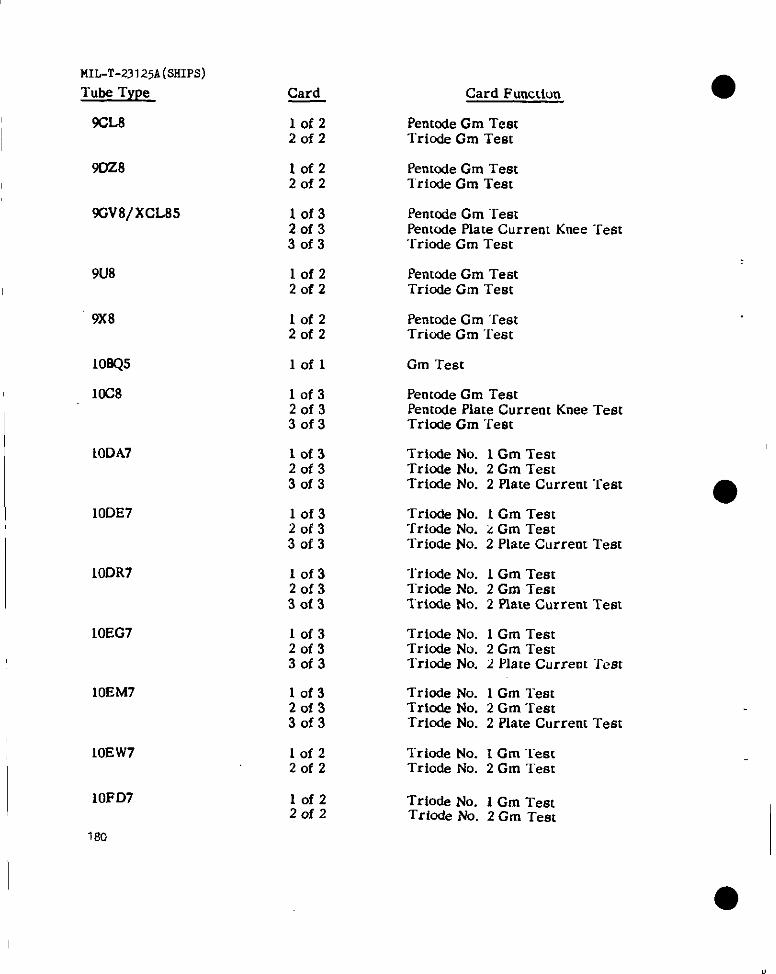
MIL-T-23125A(SSII%)
Tube Type
9CL8
9DZ8
9Gv8/xcL85
9U8
9X8
108Q5
10C8
10DA7
10DE7
10DR7
10EG7
10EM7
IOEW7
10FD7
1s0
Card
lof220f2
lof220f2
lof32of330f3
lof220f2
lof220f2
lofl
10f32of330f3
10f320f330f3
lof320f330f3
10f32of330f3
10f32of33of3
10f320f330f3
10f22of2
10f2Zofz
Card Function
Pentode Cm TestTrio& Gm Test
PentOdeCm Testlricde Cm Test
PentOdeGm “restPentode Plate Current Knee Test‘i-ride Gm Test
PentOdeGm TestTriode Cm Test
Penmde Gm ‘restTriode Cm ‘i’est
Gm Teat
PentOdeGm TestPentnde Plate Current Knee TestTriode Cm “1’est
Trirxie No. 1 Gm TestTriode No. 2 Gm TestTrinde No. 2 Plate Current Test
Triode No. 1 Gm TestTriode No. z Gm TestTriode No. 2 Piate Current Test
Trinde No. 1 Gm TestTriode No. 2 Gm TestTrinde No. 2 Plate Current Test
Triode No. 1 Gm TestTrio& No. 2 Gm TestTrio& No. 2 Plate Current ‘rest
Triode No. 1 Gm TeatTrinde No. 2 Gm TestTrinde No. 2 Plate Current Test
Trio& No. I Gm TestTriode No. 2 Gm Test
Trio& No. 1 Gm TestTrfode No. 2 Gm Test
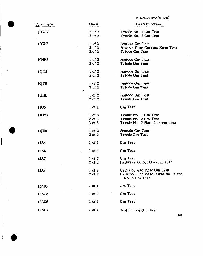
-l-me Type
10GF7
10GN8
10HF8
IOJT8
10JY8
IoL88
11C5
11CY7
11JE8
12A4
12A6
12A7
12A8
12A85
12AC6
12AD6
12AD7
MIL-T-23125A(SHIPS)
card Card Function
Iofz Trio& No. 1 Cm Test2of2 Triode No. 2 Gm “Jest
lof3 Pen[ode Gm Test2of3 Pent@dePlate Current Knee Test3.ef 3 Tricde Gm Test
lof2 Petrtale Gm Test20f2 Triode Gm Test
Iofz Pen[ode Gm TestZofz “l-ride Gm Test
lofz Pentode Gm Test2of2 Trio& Gm Test
10f2 Pentode Gm Test2of2 ‘rriode Gm Test
lofl Gm Test
10f3 Triode No. 1 Gm Test20f3 Triode No. 2 Gm ‘Test30f3 Triode No. 2 Plate Current Test
lofz Pen[ode Gm Test20f2 lriode Gm Test
lofl Gm Test
lofl Gm Test
10f2 Cm Test2of2 Hslfwave Output Current Test
lofz Grid No. 4 to Plate Gm Test20f2 Grid No. 1 to Plste. Grid No. 3 and
No. 5 Gm ‘Test
lofl Gm Test
lofl Gm Test
lofl Gm Teat
Iofl Dual Triode Gm Test181
..
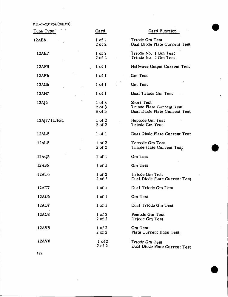
MIL-T-23 125A(SHIPS)
Tube Type_ ‘
12AE6
12AE7
12AF3
12AF6
12AG6
12AH7
12AJ6
12AJ7/HCH81
12AL5
12AL8
12AQ5
12AS5
12AT6
12AT7
12AU6
12AU7
12AU8
12AV5
12AV6
Card
lof2Zofz
lofz2of2
Iofl
lofl
lofl
lofl
lof320f330f3
10f220f2
lofl
1“of 220f2
lofl
lofl
lofz2of2
lofl
lofl
lofl
lofzZofz
10t220f2
1 0f220f2
Card Function
Trio& Gm TestDual Diude Plate Current Test
Triafe No. 1 Gm TestTriode No. 2 Cm Test
Hslfwave Output Current Test
Gm Test
Gm Test
Dual ‘rriode Cm Test
Short “restTriode Plate Current TeatDual Diude Plate Current Test
Heptode Cm Test“Iriode Gm ‘rest
Dual Diode Plate Current Test
Tetrucfe Gm TestI“riude Plate Current Te6:
Gm Test
Gm “rest
Triode Gm TestDual Diode Plate Current Test
Dual Triode Gm Test
Gm Test
Dual Triode Cm Test
Pemude Gm TestTriode Gm Test
Gm TestPlate Current Knee Test
Triode Gm TestDual Diude Plate Current Test
182

Tube Type
12AV7
12AW6
12AX4
12AX7
12AY3
12AY7
12AZ7
12&A
12BA6
12BA7
12BD6 -. .
12BE6
12BF6
12BH7A
12BK5
12BK6
12BL6
12BN6
12BQ6
12BR7
Card
I.of 1
1 of 1
lofl
lofl
lofl
,Iofl
“lofl
1 Ofl
lofl
10f220f2
lofl
lof 22of2
10f220f2
lofl
lofl
10f2Zofz
lofl
lofz20f2
10f220f2
lofz20f2
MII+T-23I25A(SHIPS)
Card Function
Dual Triode Cm Test
Gm Test
Nalfwave Output Current Test
Dual Triode Gm Test
HalfWaveOutput Current Test
Ousl Triode Gm Test
Dual Triode Cm Test
Gm’Test
Cm ‘rest
Grid No. 3 to Plate Gm Test ,:Grid No. 1 to Plate Gm Test
Gm Teat
Grid No. 3 to Plate Gm TeatGrid No. 1 to Plate, Grid No. 2 and
No. 4 Gm Test
Triodc Gm “restDual Diode Plate Current Test
Dual Triode Gm Test
Gm l’est
Triode Gm Teat~al Ditie Plate Current ‘rest
Cm ‘lest
Grid No. 1 co Plate Gm TestGrid No. 3 to Plate Gm ‘lest
Gm TestPlate Current Knee Test ;.
Trio& Gm TeatDual Diode Plate Current ‘rem
183
I ●
—
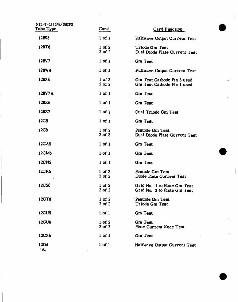
MILT-7.3 125A(sSIPS)Tube T’YW
128S3
12BT6
128V7
120W4
128X6
128Y7A
12=6
12&z7
12C5
12C8
12CA5
12CM6
12CN5
12CR6
12C36
12CT8
12CU5
12CU6
12CX6
12D41s4
Card
lofl
10f2Zofz
Iofl
lofl
IofzZofz
lofl
lofl
lofl
lofl
lof22of2
lofl
lofl
1 of, 1
10f22of2
lof220f2
lof22of2
lofl
10f2Zofz
lofl
lofl
Card Function
Hslfwave OutpuI Current Test
Trio& Gm TeetDual Diode Plate Current Test
Gm Test
Fuilwave Output Current Test
Gm Test Cathode Pfn 3 usedGm Teat Cathode Pin 1 used
Gm Test
Gm Teat
Dual Tricde Gm Teat
Gm Teat
Pentode Gm TestDuv.1Diode Place Current Test
Gm Test
Gm Test
Gm Test
Penmde Gm TestDiode Piate Current Teat
Grid No. 1 to Plate Gm TestGrid No. 3 to Piate Gm Test
Pentode Gm TestTriode Gm Test
Gm Test
Gm Testplate Current Knee Test
Gm Test
Halfwave Output Current Test
I.. -—
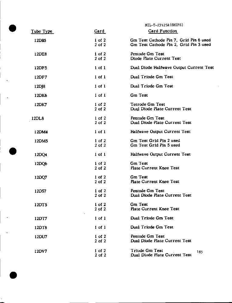
● Tube TypeMIL-T-23125A(SHIPS)
Card Function
Gm Test Cathode Pin 7, Grid pin 6 usedGm Tea Cathode Pin 2, Grid Pin 3 ueed
Card
Iofz2of2
12D8S
12DE8 Iofz20f2
Pentode Gm TestDiode Plate Current Test
Dual Diode HalfWaveOutput Current Test12DFS
12DF7
lofl
Dual Tricde Cm Testlofl
Dual Triode Cm Test
Gm Test
Tetrode Gm TestDIIaJDiode Plate Current Test
12DJ8
12DK6
12DK7
lofl
Iofl
10f220f2
12DL8 10f220f2
Penmde Gm TestDual Diode Plate Current Test
Hslfwave Dutput Current Test12DM4
12DM5
lofl
lofz2of2
Gm Test Grid Pin 2 usedGm Test Grid Pin 5 used
● 12DQ4 Iofl Hslfwave ~tput Current Test
12DQ6 lof220f2
Gm TestPlate Current Knee Test
12DQ7 10f2Zofz
Cm TeatPlate Current Knee Test
lofz2of2
Pentode Gm TeatD.Ial Diode Plate Current Test
Gm TestPlate Current Knee Teat
12DS7
12DT5 lof2Zofz
12DT7
12DT8
12DfJ7
lofl Dual Tricde Gm Test
Dual Triode Gm TestIofl
Pemode Gm TestDud Diode Plate Current Test
lof220f2
12DV7 10f22of2
Triude Gm Test 185Dual Diode Plate Currem Test
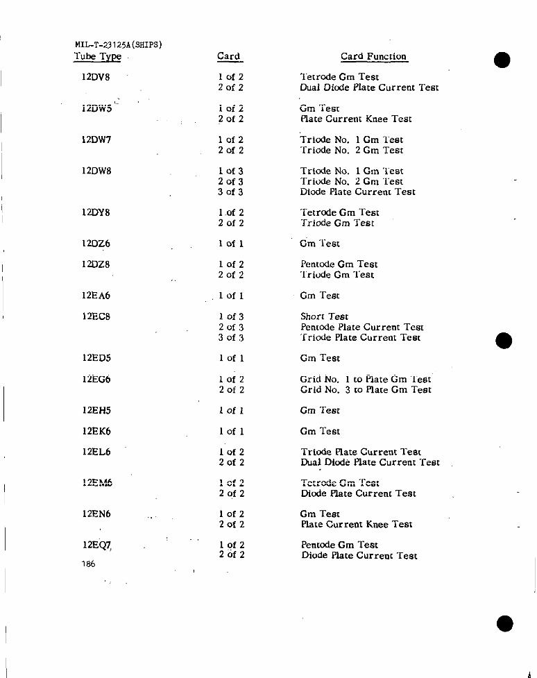
MIL-T-23125A(sIf1w)Tuk Type
I 12DV8
12DW5“;
12Dw7
12DW8
12DY8
12DZ6
12DZ8
12EA6
12EC8
12ED5
12EG6
12EH5
12EK6
12EL6
12EM6
12EN6
12EQ7
184
Card
10f22of2
lof22of2
10f22of2
lof32of330f3
1.Of220f2
lofl
10f220f2
lofl
10f320f330f3
lofl
lof220f2
lofl
Iofl
lof220f2
10f220f2
10f22of2
10f220f2
Card Funcrion
T’ecrcdeCm TestDual Dicde Plate Current Test
Gm TestPlate Currem Knee Test
Triode No. 1 Cm Test“rriode No. 2 Gm Test
Triode No. 1 Gm TestTriode No. 2 Cm “restDiode Plate Current Test
Tetrode Gm TestTriode Gm Test
Gm Test
Pentcde Gm Test‘Iriode Gm “lest
Gm Test
Short TestPenmde Plste Current Test‘rriode Plate Current Test
Cm Test
Grid No. 1 to Plate Gm TestGrid No. 3 to Plate Gm Test
Gm Test
Cm Test
Triode Plate Current TestDual Diode Plate Current Test
Tetrode Gm TestDimfe Plate Current Test
Cm TestPlate Cur rent Knee Test
Pent@deGm TestDiode Plate Current Test
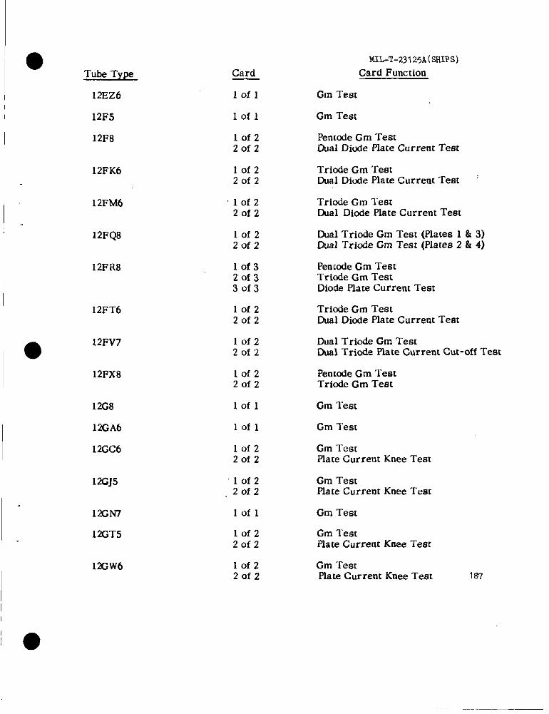
●Tube Type
12EZ6
12F5
12F8
12FK6
12FM6
12FQ8
12FR8
12FT6
●12FV7
12FX8
12G8
12GA6
12GC6
12GJ5
12GN7
12GT5
12GW6
Card
Iofl
Iofl
10f22of2
Iofz20f2
‘10f220f2
10f22of2
10f320f330f3
lofz20f2
lofz20f2
lof220f2
lofl
lofl
lof220f2
“lofz,20f2
lofl
lofz20f2
10f220f2
NIL-T-231 25A(SHIPS)
Card Function
Gm Test
Gm Test
Penuxie Gm TestDual Diude Plate Current Test
Triode Gm TestDual Diode Plate Current Test :
Triode Gm TestDual Diode Plate Current Test
Dual Triode Gm Teat (Plates 1 & 3)Cual Tricde Gm Test (PIares 2 & 4)
Penmde Gm TestTrinde Gm TestDiode Plate Current Test
Triode Gm TestDual Diode Plate Current Test
Dual Triode Gm TestDual Triede Plate Current Cut-off Test
Penmde Gm TeatTrinde Gm Test
Gm Test
Gm Test
Gm TestPiate Current Knee Teat
Gm TestPlate Current Knee Test
Gm Test
Gm TestPlate Current Knee Test
Gm TestPlate Current Knee Test 1s’/
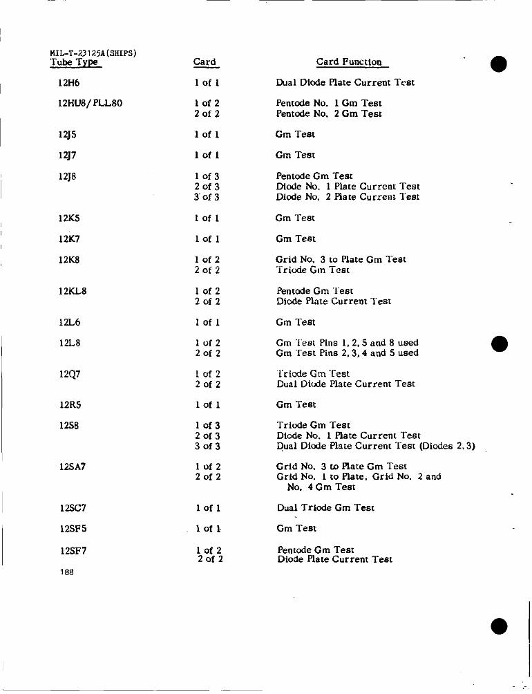
MI;~T-;3125A(sHIPs)YPe
12H6
12HU8/PLL80
12]5
12J7
12J8
12K5
12K7
12K8
12KL8
12L6
12L8
12Q7
12R5
12S8
12SA7
12SC7
12s2?5
12SF7
188
Card
lofl
Iofz2of2
Iofl
Iofl
10f32of330f3
Iofl
lofl
lofzZofz
lofzZofz
lofl
10f220f2
lofz20f2
lofl
lof32of330f3
10f2Zofz
lofl
1 of 1.
10f2Zofz
Card Function‘0
Dual Ditde plate Current Test
Pentcde No. 1 Cm TestPentOdeNo. 2 Gm Test
Gm Test
Gm Test
Penmde Gm TestDiode No. 1 Plate Current TestDiode No. 2 plate Current Test
Gm Test
Gm Test
Grid No. 3 to flate Gm TestTricde Cm Test
PentOdeGm TeetDiode PIate Current Teat
Gm Test
Gm “l’eatPins 1,2,5 and 8 usedGm Teat Pins 2,3,4 and 5 used
Triode Cm TestDual Diude Plate Current Test
Gm Test
Triode Cm TestDiode No. 1 Piate Current TestQual Dicde Plate Current Test (Diodes 2,3)
Grid No. 3 to Plate Gm TeatGrid No. 1 m plate, Grid No. 2 and
No. 4 Gm Test
Dual Triode Gm Test
Gm Test
Pentcde Gm TestDiode Plate Current Test
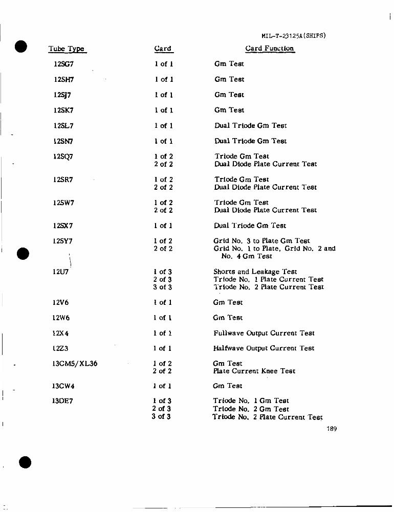
● -rub-eType
MIL-T-23125A(SHIPS)
Card
lofl
Card Function
Gm Test12SG7
12SH7
12Sj7
12SK7
12SL7
lofl Gm Test
Iofl Gm Test
Gm Teatlofl
lofl Dual Triode Gm Test
12SN7
12SQ7
lofl
10f22of2
Cual Triode Gm Test
Triode Gm TestDual Diode Plate Current Teat
12SR7 10f220f2
Triode Gm TeatDual Dinde Plate Current Teat
12SW7 lof220f2
‘rriode Cm TeatDual Dinde Plate Current Teat
123X7 Dual Triode Gm Teat
Grid No. 3 to Plate Gm TestGrid No. 1 to Plate, Grid No. 2 and
No. 4 Gm Test
Iofl
Iofz20f2
12SY7
●❉
12U7 lof320f330f3
Shorts and Leakage TestTrlode No. 1 Plate Current Testlrinde No. 2 Plate Current Teat
12V6
12W6
12X4
12Z3
13CM5/XL36
lofl Gm Test
lofl
lofl
lofl
Gm Test
Fullwave Output Current Teat
HaMwaveOutput Current Test
lof220f2
lofl
lof32of33of3
Gm TeatPlate Current Knee Teat
13CW4
13DE7
Cm Test
Triode No. 1 Gm TeatTriode No. 2 Gm TestTriode No. 2 Plate Current Test
1S9
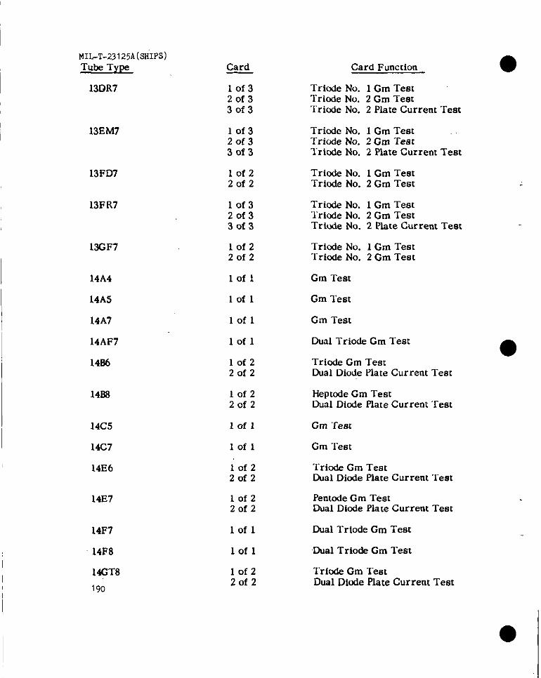
MIL-T-23125A(sHIpS)Tube Type
13DR7
13EM7
13FD7
13FR7
13GF7
14A4
14A5
14A7
14AF7
14B6
1468
14C5
14C7
14E6
14E7
14F7
14F8
14GT8
190
*
10f32of330f3
lof320f33of3
lof220f2
lof32of330f3
10f220f2
lofl
lofl
lofl
lofl
lofz20f2
10f22of2
lofl
Iofl
10f2Zofz
lofz20f2
lofl
lofl
10f22of2
Card Function
Triode No. 1 Gm TestTriode No. 2 Gm TestTriode No. 2 Plate Current Tem
Triode No. 1 Gm TestTriode No. 2 Gm TestTriodeNo. 2 PlateCurrentTest
Triode No. 1 Cm TestTriude No. 2 Gm Test
Triode No. 1 Gm Test‘lriode No. 2 Gm TestTriode No. 2 Plate Current Test
Triode No. 1 Gm Test“I”ricdeNo. 2 Gm Test
Gm Test
Gm Test
Gm Test
Dual Triode Gm Test
Triode Gm TestDual Diode Plate Current Test
Heptode Gm TestDual Diode Plate Current Test
Gm ‘rest
Gm Test
“~riode Gm Test~al Diode Plate Current Test
Pentode Gm TestDual Diode Plate Current Test
Dual Triode Gm Test
Dual Trio& Gm Test
Tricde Gm TemDual Diode Plate Current Test
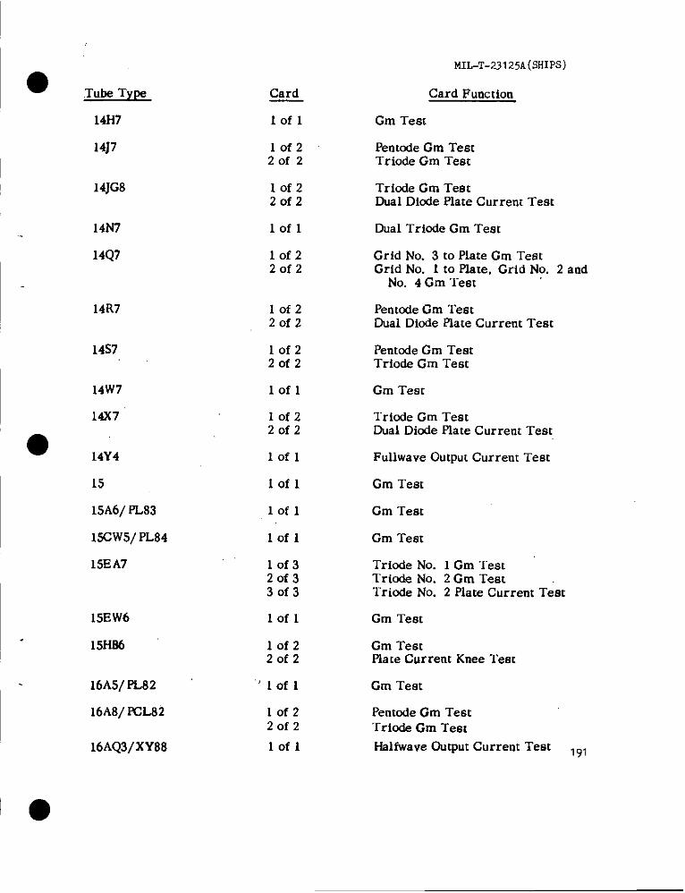
● Tube Type Card
14H7 lofl
14J7 10f220f2
14JG8 Iofz2of2
14N7 lofl
14Q7 lof220f2
14R7 lof22of2
14s7 lof22of2
14W7 lofl
14X7
● 14Y4
IofzZofz
lofl
15 Iofl
15A6/ PL83 lofl
lSCW5/ PL84 lofl
15EA7 10f320f33of3
15EW6 lofl
15H86 lofz20f2
16A5/ PL82 “lofl
16A8/ FCL82 lofz20f2
16AQ3/XY88 lofl
MIL-T-231 25A(SHIPS)
Card Function
Cm Test
Penmde Gm TestTriode Gm Teat
Triode Gm TestDual Diode Plate Current Test
Dual Triode Gm Test
Grid No. 3 to Plate Cm TeatGrid No. 1 to Plate, Grid No. 2 and
No. 4 Gm Test
Pentode Gm TestDual Diode Plate Current Test
Pentde Cm TestTriode Gm Test
Gm Tear
Triode Gm TestDual Diode Plate Current Teat
Fullwave Output Current Test
Gm Test
Gm Test
Gm Test
Tricde No. 1 Gm TestTrio& No. 2 Gm TestTriode No. 2 Plate Current Test
Gm Test
Cm Testflare Current Knee Test
Gm Test
Pentode Gm TestTriode Gm Test
Halfwave Output Current Test 191
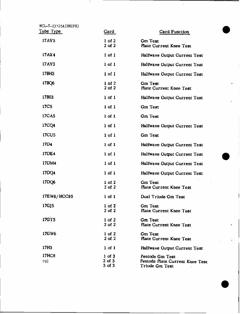
!.m,-T-23125A(smPs)Tube Type
17AV5
17AX4
17AY3
17BH3
17333
17CS
17CA5
17CQ4
17CU5
17D4
17Dli4
17DM4
17DQ4
17DQ6
17EWil/HCC85
17GJ5
17GT5
17GW6
17H3
17HC8192
Card
lof22of2
lofl
lofl
lofl
lof22of2
lofl
1 of .1
Iofl
lofl
lofl
lofl
lofl
lofl
lofl
1of22of2
lofl
lof220f2
lof22of2
10f220f2
lofl
10f320f330f3
Card Function
Gm TestPlste Current Knee Test
Hslfwave output Current Teat
HalfWaveoutput Current Test
Halfwave Output Current Test
Cm TeatPlate Current Knee Test
HalfWaveOutput Current Test
Cm Test
Gm Test
Halfwave Output Current Test
Gm Test
●
Halfwave Output Current Test
Hslfwave output Current Test ●Halfwave Output Current Test
Halfwave Output Current Test
Cm TeatPlate Current Knee Test
Dual Tricde Gm Teat
Gm TeatPlate Current Knee Test
Cm TeatPlate Current Knee Test
Gm TestPlate Current Knee Test
Hsifwave output Current Test
Pentcde Gm TestPentode Flate Current Knee TestTriode Gm Teat
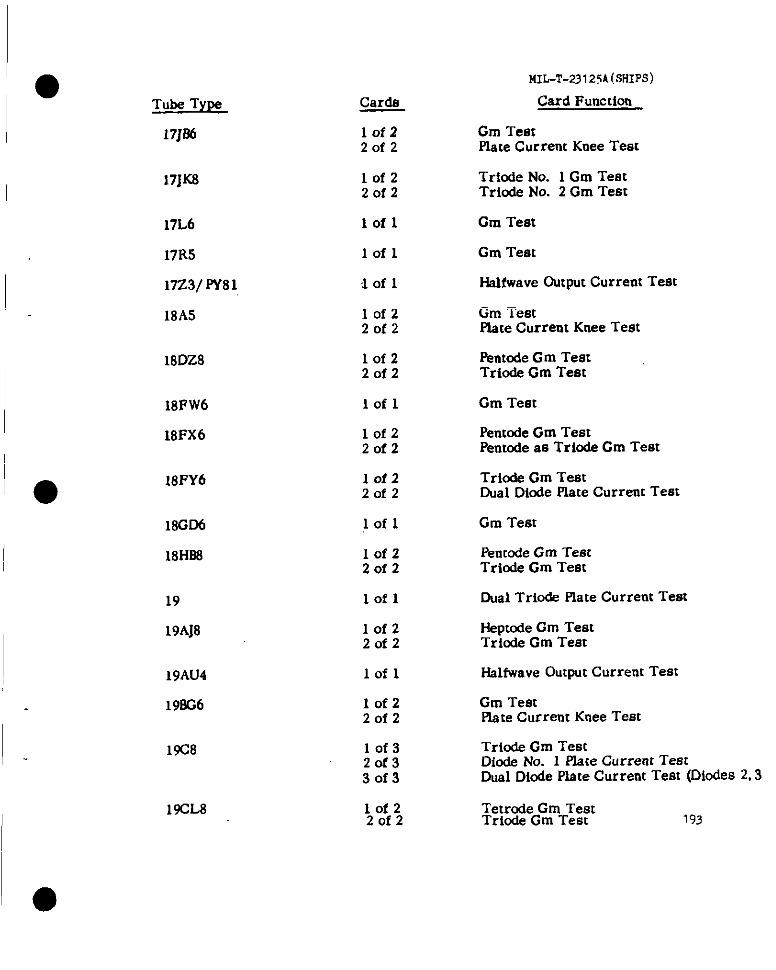
MIL-T-23125A(SHIPS)
Card Function
Gm Te8cPlate Current Knee Test
Tube Type
17J86
Cards
10f220f2
10f22of2
17JX8 Triode No. 1 Gm TeatTriode No. 2 Gm Test
17L6
17R5
17Z3/ PY81
18A5
lofl Gm Test
Gm Testlofl
Halfwave Output Current TeatIofl
lof22of2
lof220f2
Iofl
lof22of2
Gm TestPlate Current Knee Test
Pmtode Gm TestTriode Gm Test
18DZ.8
18PW6
18FX6
Gm Test
Pentode Gm TestPentode as Trlode Cm Test
Triode Gm TestOual Diode Plate Current Test
Gm Test
PertcodeGm TestTrio& Gm Test
18FY6 lofz20f2
lofl18GD6
18HB8 10f22of2
Dual Trio& Plate Current Testlofl19
19AJ8 Hepmde Gm TestTriode Gm Teat
lof22of2
Halfwave Output Current Test
Gm TestPlate Current Knee Test
19AU4
19=6
lofl
lof22of2
10f320f330f3
19C8 Trio& Gm TestDiode No. 1 Plate Current TestDual Diode Plate Current Teat (Diodea 2,3
1$CL8 10f22of2
Tetrode Gm TestTricde Gm Test 193
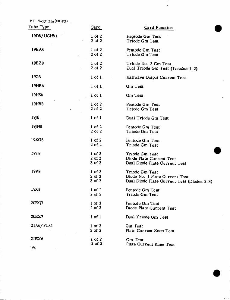
I
MILT-23125A(SHIPS)Tube Type Card
19D8/UCH81 lofzZofz
19EAtl lofzZofz
19EZ8 lofzZofz
1%3 Iofl
19HR6 lofl
19HS6 lofl
19HV8 IofzZofz
19J6 lofl
19JN8 lofzZofz
19KG8 lofzZofz
19T8 10f320f330f3
19V8 10f32of330f3
19X8 10f2Zofz
20EQ7 lofzZofz
20EZ7 lofl
2lA6/ PL81 lofzZofz
21EX6
194
lofzZofz
Card Func[ion
Hepmde Cm TestTriode Gm Test
Penmde Cm Test‘rriude Cm Test
‘Triode No. 3 Cm TeatDual Triode Gm Test (Triodes 1,2)
f-lslfwave output Current Test
Gm Test
Gm Test
Penmde Cm Test‘Triude Gm ‘rest
Dual Triode Cm Test
Pentode Gm TestTriode Gm Test
Pentode Gm Test“Iricde Gm Test
‘~riode Gm Test ●Diode Plate Current TestDual Diode Plate Current Teat
Triode Gm TestDiode No. 1 flare Current TestDual Diode Plate Current lest (Dicdes 2,3)
Pentode Gm TestTriodc Cm Teat
Pentode Cm TestDiode Plate Current Test
Dual Triode Gm Test
Gm Testplate Current Knee Test
Gm Testplate Current Knee Test
●
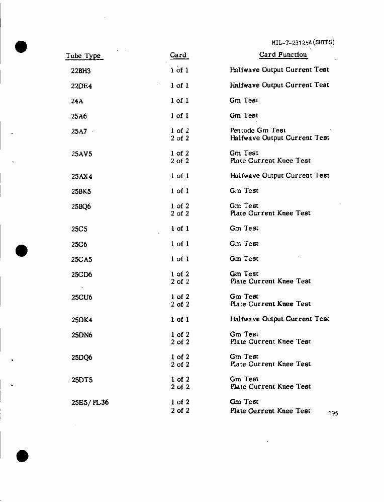
MIL-T-23125A(sHIps)
Card Function
Halfwave Output Current Test
●Tube ‘rype Card
22BH3 lofl
Halfwave output Current Test
Gm Test
Gm Test
22DE4 lofl
lofl24A
25A6
25A7
Iofl
10f220f2
Penmde Gm TestHalfwave Output Current Test
25AV5 lof220f2
Gm TestPla[e Current Knee Test
Iofl Halfwave Output Current Teat
Gm Test
25A)(4
25BK5
25BQ6
lofl
10f220f2
Gm TestPlate Current Knee Test
Gm Test25C5 lofl
Gm Test2S6 lofl
Gm Test
Gm TestPlate Current Knee Test
23CA5
25CD6
lofl
lof22of2
25CU6 10f22of2
Gm TeatPlate Current Knee Test
Halfwave Output Current Test25DK4
25DN6
lofl
Gm TestPlate Current Knee Test
Gm TestPlate Current Knee Test
lof220f2
25DQ6
2SDTS
25E5/ PL36
10f220f2
I iof220f2
Gm TestPlate Current Knee Test
Cm TestPlate Current Knee Test 195
10f22of2
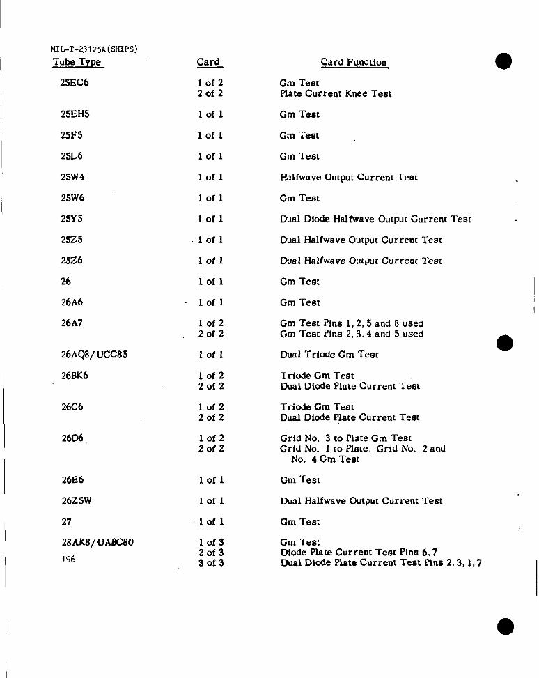
MIL-T-231 25A(SHIPS)
Tube Type
2SEC6
25EH5
25F5
25L6
25W4
25W6
25Y5
25Z5
25Z6
26
26A6
26A7
26AQ8/UCC85
26BK6
2606
26E6
26Z5W
27
28AK8/UA8C80
196
Card
lof2Zofz
lofl
Iofl
lofl
lofl
lofl
lofl
Iofl
lofl
lofl
lofl
lof220f2
Iofl
10f22of2
lofz20f2
10f2Zofz
Iofl
lofl
lofl
10f320f33of3
Gm TestPlate Current Knee Teat
Gm Test
Gm Teat
Gm Teat
Halfwave Output Current Teat
Gm Test
Dual Diode Halfwave Output Current lest
Dual Halfwave Output Current Test
Dual HalfwrrveOutput Current Test
Gm Test
Gm Teat
Gm Test Pins 1,2,5 and 8 usedGm Teat Pins 2.3.4 and 5 used
Dual Triode Gm Test
Triode Gm TeatDud Diode Plate Current Test
Triode Gm TeatDual Diode ~ate Current Test
Grid No. 3 to Plate Gm TeatGrid No. 1 to Plate, Grid No. 2 and
No. 4 Gm Teat
Gm Test
Dual Halfwave Output Current Test
Gm Test
Gm TeatDiode Plate Current Test Pins 67Dual Dicde Plate Current Test Pins 2.3, 1,7
-..

● Tube TyLM
MIL-T-23125A(sHIPs)
Card Function
Cm Test Pins 3,5,6 and 7 usedCm Test Pins 2,3,4 and 6 used
Plate Current Test
Card
lof220f2
28D7
30
31
32
32ET5
32L7
lofl
lofl Plate Current Test
lofl Plate Current Test
Cm Test G Pin 2 usedlofl
lofz2of2
Iofl
lofl
Gm TestHslfwave Output Current Test
Cm Test
Gm Test
34GD5
35
35A5
3505
35C5
lofl Gm Test
lofl Gm Test
lofl Cm Teat
Cm TestPlate Current Knee Teet
Pemode Cm TestTriode Cm Test
● 3SCD6 10f22of2
35DZ8 lof2
Zofz
35EHS
3XL6
35HB3
lofl Gm Test
lofl
lofz2of2
lofl
lofl
Gm Test
Pentode Cm TestTriode Cm Test
Gm Test
Halfwave Output Current Test
35L6
35W4
35Y4 HalfWaveOutput Current Teatlofl
3523
3324
Iofl Halfwave Ouqmt Current Test
HaMwaveOutput Current Test
1?-/
I

MIL-T-23125A(SHIPS)
Tube Type
3525
3526
36
36AM3
37
38
38.43/ UY85
39/ 44
40FR5
41
42
43
45
45Z3
46
47
48
50A5
5035
50BK5
50BM8/UCL82
50C5
50C6198
Card
Iofl
Card Function
Halfwave Output Current Test
lofl Dual Diode Halfwave Output Current Test
Gm Testlofl
lofl
lofl
fial~ Output Current Test
Gm Teat
lofl Gm Test
Halfwave Output Current Testlofl
lofl Gm Teat
Iofl
Iofl
lofl
lofl
Gm Test pin 2 used
Gm Test
Gm Test
Gm Test
●lofl Gm Teet
Halfwave Output Current Test Pin 6 usedHalfwave Gutput Current “Iest Pin 2 used
10f220f2
lofl
lofl
Plate Current Test
Gm Teet
lofl Gm Test
Gm Testlofl
Iofl Gm ‘Teat
Iofl
lof22of2
Gm Test
Pentmie Cm Test Pin 2.3.6 and 7Triode Plate Current Test pin 1,8,9
lofl Gm Test
lofl Gm Test
1\
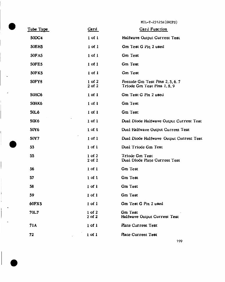
● Tube TYPS
MIL-T.23 I 25A(5HIPS)
Card Function
Halfwave Output Current Test
Card
Iofl500C4
.50EH5
SOFAS
50FE5
50FK5
Cm T’est G PiII 2 usedlofl
lofl
Iofl
Iofl
lof22of2
Gm Test
Gm Test
Cm Test
Pentode Gm Test Pins 2,3,6.7Triode Gm ‘rem Pina 1,8, 9
50FY8
50HC6 lofl Gm Teat G Pin 2 used
50HK6 Gm Testlofl
50L6 Gm TestIofl
lofl
lofl
lofl
50X6 Oual Dicde Halfwave Output Current Test
50Y6 Dual Halfwave Output Current Test
Oual Diode Halfwave Ou[put Current Test50Y7
● ,, lofl Dual Triude Gm Test
55 lof2Zofz
Triode Gm TestDual Dicde Plate Current Tem
56
57
58
59
60FX5
lofl
lofl
Iofl
Iofl
Gm Test
Gm Test
Gm Test
Cm Test
Gm Tem G Pin 2 usedlofl
70L7 lof2Zofz
lofl
Gm TestHalfwave Output Current Test
71A
72
Plate Current Test
lofl Place Current Test
199
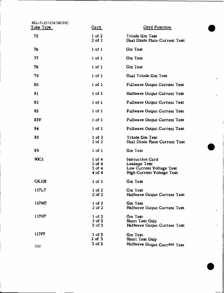
MIL-T-23125A(SSIPS)Tuke Type
75
76
77
78
79
80
81
82
83
83V
84
85
89
90C1
CK108
117L7
117M7
117N7
117P?
200
Card
Iofz2of2
lofl
Iofl
lofl
lofl
Iofl
lofl
Iofl
lofl
lofl
lofl
10f220f2
lofl
lof42of43of440f4
lofl
lof220f2
lofz20f2
lof32of330f3
10f320f330f3
Card Function ●Tricde Gm TestDual Dicde Plate Current Test
Gm Test
Gm Test
Gm Test
Dual Trio& Gm Test
Fullwave Output Current Test
Halfwave Output Current Test
FuUwsve Output Current Test
Fullwave Output Current Test
Ftdlwave Output Current Test
Fullwave Output Current Test
Triode Gm TeatDual Diode Flate Current Test
Gm Test
Instruction CardLeaksge TeatLow Current Voltage TestHfgh Current Voltsge Test
Gm Test
Gm l“estHalfwave Output Current Test
Gm TestHalfwave Output Current Test
Gm TeatShort Test OnlyHslfwave Output Current Test
Gm TestShort Test OtdyHalfwave out~t Current Teat

● Tube Type
117Z3
117Z4
117Z6
x 155
TS251
292A
303A
307A
311A
347A
●351A
384A
395A
502A
CK512AX
CK526AX
CK533AX
559
CK573AX
Card
lofl
Iofl
Iofl
Iofl
Iofz20f2
10f22of2
10f220f2
lofl
lofl
lofl
lofl
Iofz20f2
10f320f330f3
10f32of330f3
lofl
Iofl
lofl
.1of 1
lofl
MII.-T-23 I 25A(sHIpS)
Card Function
Hslfwave Output Current Test
Hslfwave Output Current Test
Oual Hslfwave Output Current ‘rest
Dual Triode Gm Teet
Penmde Gm Teat Pins 3.4,5,8HsMvave Output Current ‘I’eat Pins 1,6
Triode Gm TestPlate Current Test
Tricde Cm TeatOiode Plate Current Test
Plate Current Test
Gm Test
Gm Test
Fullwave Output Current Test
Instruction CardCm Test
Instruction CardScarcer Voltage DropAnode Voltage Drop
Cathode Current TestPlste to Cathode Voltage TestPlate Current Cut-off Test
Pentode as Triode Cm Test
Plate Current Teat
Rate Current Teat
PIate Current Test
Plate Current Teat201
●
1
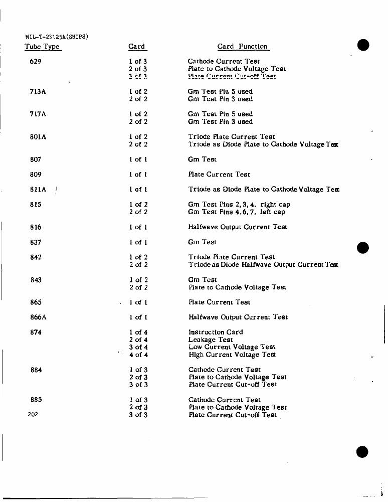
MIL-’T-23125A(SKIPS)
Tube Type
629
713A
717A
801A
807
809
811A J
815
816
837
842
843
865
866A
874
884
885
202
Card
10f320f330f3
lof22of2
10f220f2
lof220f2
Iofl
Iofl
lofl
10f220f2
Iofl
Iofl
10f220f2
lofz20f2
Iofl
Iofl
10f420f430f4,.40f4
10f320f330f3
10f32of33of3
Card Function
Cathode Current TestPlate to Cathode Voltage Testplate Current Cut-off Test
Cm Test P{rt5 usedCm TestPin3 used
Cm Test Pin 5 usedCm Test Pin 3 used
Triode Piate Current Testlriwie aa Diode Plate to Cathode Voltage T=
Cm Teat
Plate Current Test
Triode as Diode Plate to Cathode Voltage TeS
Cm Test Pins 2,3,4, right capCm Test Pins 4,6,7, left cap
Hslfwave Output Current Test
Cm Test●
Triode Phte Current TestTriode aa Diode Halfwave Output Current T=
Cm TestPlate to Cathode Voltage Test
Plate Current Test
Halfwave output Current Test
Instruction CardLeakage TestLow Current Voltage TestHigh Current Voltage Tet4
Cathode Cur rent TestFlate to Cathode Voltage TestPlate Current Cut-off Test
Cathode Current TestPlate to Cathcde Voltage TestPlate Current Cut-off Test
.i— .—
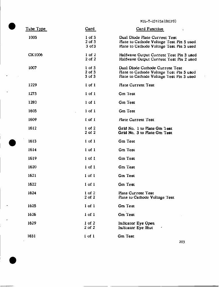
II
‘o
MIL-T-231 25A(SHIPS)
Card Function
Dual Diude Plate Current TestPlate to Cathcde Voltage ‘Test Pin 5 usedPiate to Cathode Voltage “TestP1n3 used
● Tube Type Card
10f320f33 of3
1005
CK1006 lof2
20f2Halfwave Output Current Teat Pin 3 usedHalfwave Output Current Test Pin 2 used
1007 10f32of33of3
Dual Diode Cathode Current TestPlate to Cathode Voltage l-caL Pin 5 usedPlate to Cathode Voltage l’est Pin 3 used
1229
1273
1280
1603
1609
1612
lofl Plate Current Teat
lofl Gm “rest
Gm Test
Gm Test
Iofl
Iofl
Iofl Piate Current Test
lofz2of2
Grid No. 1 to Plate Gm 1 aetGrid No. 3 to Piate Gm Test
● 1613
1614
lofl Gm Test
lofl Gm Teat
Cm Test
Cm Test
1619 lofl
1620 lofl
1621
1622
Cm Test
Iofl Gm Test
1624 lofz20f2
Plate Current TeatPiate to Catitcde Voltage “lest
Gm Test
Cm “Teat
1625
1626
lofl
Iofl
1629
1631
10f220f2
Indicator Eye OpenIndicator Eye Shut ~
lofl Cm Test203
.——.
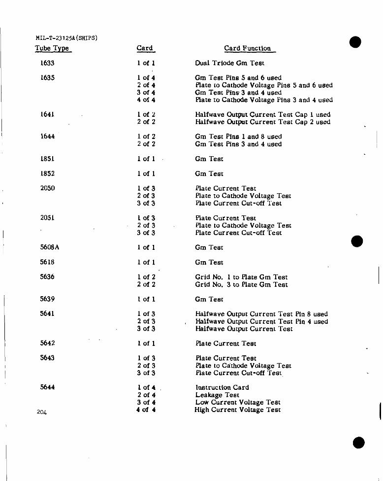
I
I
r.m-T-23I25A(sH1ps)
Tube Type
1633
1635
1641
1644
1851
1852
2050
2051
5608A
5618
5636
5639
5641
5642
5643
5644
204
Card
lofl
10f420f43of440f4
lof2Zofz
lofzZofz
lofl
lofl
10f320f330f3
Lof320f330f3
lofl
lofl
lof2Zofz
lofl
10f32of33of3
Iofl
lof320f330f3
10f42of430f440f4
Card Function
Oual Triode Gm Test
Cm Test Pina 5 and 6 usedPlate to Cathode Voltage Pins 5 and 6 usedGm Test Pins 3 and 4 usedPlate 10 Cathode Voltage Pins 3 and 4 used
Hslfwave Output Current Teat Cap 1 usedHalfwave Output Current Test Cap 2 used
Cm Teat Pins 1 and 8 usedGm Test Pins 3 and 4 used
Gm Test
Gm Test
Plate Current TeatPlate to Cathode Volmge TestPlate Current Cut-off Test
Plate Cur rent TestPlate m Cathode Voltage TestPlate Current Cut-off Test
Gm Teat
Gm Test
Grid No. 1 to Plate Gm TestGrid No. 3 to Plate Gm Test
Gm Test
Halfwave Output Current Test Pfn 8 usedHrdfwave Output Current Test Pfn 4 usedHslfwave Output Current Test
Plate Current Test
Plate Current TestPlate to Cathode Voltage TestPlate Current Cut-off Test
lnscruction CardLeakage TestLow Current Voltage TestHigh Current Voltage Test
I
I●
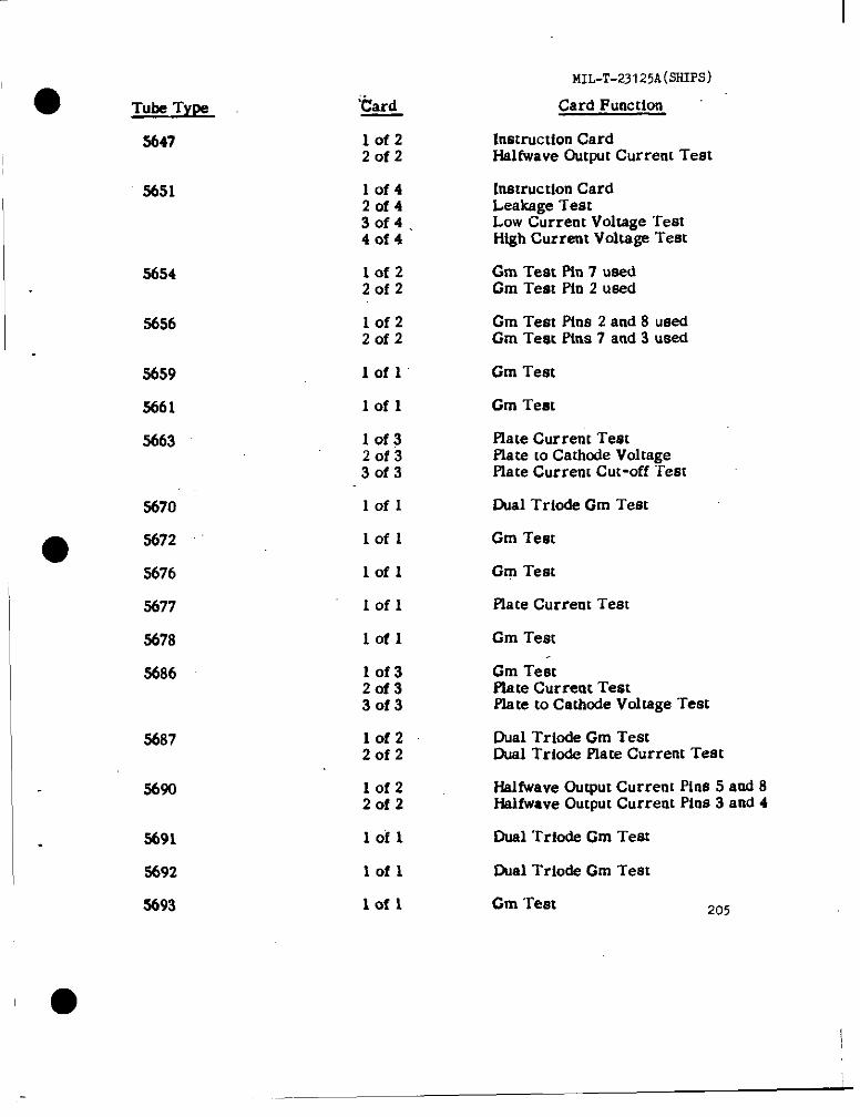
‘o Tube TYW
3647
3651
5654
5656
5659
5661
5663
5670
●5672
5676
5677
5678
3686
3687
5690
5691
%92
3693
‘Card
lof220f2
10f42of43of4.4of4
lof22of2
lof22of2
lofl”
lofl
lof32of33of3
lofl
Iofl
Iofl
lofl
lofl
lof32of330f3
10f22of2
lof220f2
lofl
lofl
Iofl
MIL-T-23125A@HIPS)
Card Function
Inatructlon CardHalfwave OutpuCCurrent Test
[netructlon CardLeakage TestLow Current Voltage TeatHigh Current Voltage Teat
Gm Test Pin 7 usedGm Test Pin 2 used
Gm Test Pins 2 and 8 usedGm Test Pltts 7 and 3 used
Gm Test
Gm Teat
Plate Current TestPlate to Cathode VoltagePlate Current Cut-off “Ieat
~al Trlode Gm Test
Gm Test
GgI Test
Flate Current Test
Gm Test
Gm TestPlate Curreot TestPlate to Cathode Voltage Teat
Oual Triode Gm TeatOual Trio& Plate Current Teat
Halfwsve Output Current Pins 5 and 8f-ialfwaveOutput Current Pins 3 and 4
Oual Trio& Gm Test
Oual Trio&Cm Test
Gm ‘rest 205
I
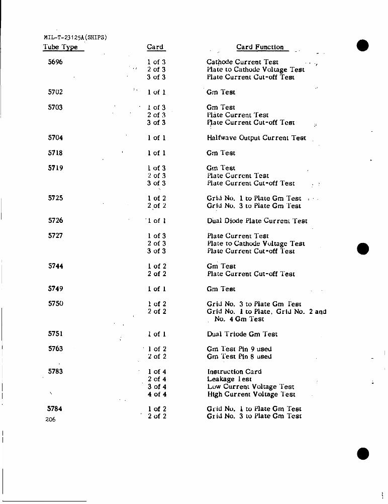
MIL-T-23125A(SHIPS)
Tube “fype
5696
Card Card Function
Cathode Current Test ~Plate co Cathode Voltage TestHate Current Cut-off Test
10f3. 20f3
30f3
:, Iofl
10f320f330f3
5702
5703
Gm Test
Cm TestPlate Current Test~te Current Cut-off Test
5704
5718
5719
Iofl Halfwave Output Current Test
lofl Gm Test
Gm TestPlate Current TestPlate Current Cut-off Test ~
10f320f330f3
5725 lof22 ,Of2
Grid No. 1 to Plate Gm Test ,Grid No. 3 to Plate Gm “Test
Did Diode Plate Curreni “~est5726
5727
‘Iofl
10f320f33of3
Plate Current l“estPlate to Cathode Voltage TestPlate Current Cut-off Teat
I 5744 Grn TestPlate Current Cut-off Test
10f2Zofz
lofl
10f220f2
5749
575fJ
Gm Test
Grid No. 3 m Plate Gm lestGrid No. 1 to Plate, Grid No. 2 and
No. 4 Gm l“est
5751
5763
lofl Dual Triode Gm Test
Gm Test Pin 9 usedGm “lest Pin 8 used
10f220f2
I 5783 10f420f430f44of4
10f22of2
Instruction CardLeakage i estLuw Current Voltage “lestHfgh Current Voltage ‘1’est\
5784206
Gl”id No. 1 to Plate Gm “restGI id No. 3 to Plate Gm Test
I

● Tube Type
5787
5798
5812
5814A
5829
5838
5839
5840
5842
●5844
5847
5852
5854
5875
5879
5881
5886
Card
lof42of430f44of4
Iofl
lofl
Iofl
lofl
lofl
Iofl
lof320f33of3
10f42of430f4
40f4
10f32of330f3
lof32of33of3
Iofl
.lofl
Iofl
lofl
lofl
10f2”20f2
lofl
MIL-T-231 25A(SlfIR3)
Card FulrctiOn
Instruction CardLeakage lestLow Current Voltage TestHigh Current Voltage Test
Dual Triode Gm Test
Plate Current Test
Dual Triode Gm Test
Dual Diode Plate Current Teat
Fullwave Dutput Current Test
Fullwave Output Current Test
Gm TestPiate Current TestPlate Current Cut-off Test
Gm Test Pin 8 usedPlate Current Test Pin 7 usedPlate Current Test Pin 5 usedPlate Current Cut-off Test Pin 4 used
Dual Triode Gm TestDual ‘fride Plate Current Test ~‘Dual “I_riodePlate Current Cut-off Test
Gm TestPlate Current TestPlate Current Cut-off Test
Fullwave Output Current Test
Plate Current Test
Plate Current Test
Cm Test’
Gm Test
Short Test OnlyPlate Current Test
Dual Diode Plate Current Test 207

MIL-T-23125A(SHIPS)
Tube Type
5899
5932
5903
5904
5905
5936
5907
5908
5910
5915
I 5920/E90CC
5930
5931
5932
5933
208
Card
lof32of33of3
10f32of330f3
lofl
lofl
10f32of330f3
10f32of33of3
10f32of33of3
10f2Zofz
10f22of2
lof420f43of440f4
lof32of330f3
Iofl
lofl
lofl
lofl
Card Function
Cm TestPlate Current TestGm Cut-off Test
Cm TestPlate Current lestPiate Current Cut-off Test
Dual Diode Plate Current Test
Cm Test
Cm TestPiate Current TestIlate Current Cut-off Test
Cm TestPlate Current TestPlate Current Cut-off Test
Gm Test Pin 8 usedCm Test Pin 4 usedFlace Current Test Pin 2 used
Gm TestPlate Current Test
Piate Current TestPlate Current Cut-off Test
Cm TestPlate Current TestPlate Currettt Cut-off TestPlate Current Cut-off Test
Dual Trlode Cm TestDual Triode Plate Current TestDual T’riode Plate Current Cut-off Test
Plate Current Test
Fullwave Gutput Current Test
Gm Test
Cm Test
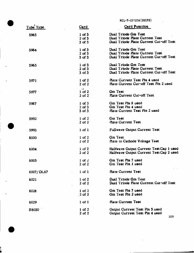
●Tube’Type
MIPT-23 I 25A(SI+IpLi)
Card Fuecclon
Dual Triode Gm TestOual Tri* Plate Currettt TestOusl Triode Piete Current Cut-off Test
Oual Triode Gm TestOusl Triode Piste Current TestW Triode Piste Current Cut-off Test
Card
lof32of33of3
5%3
5%4 lof320f33of3
lof32of33of3
5%5 Cual Triode Cm TestDual Trio& Plate Current TestDual Triode Plate Current Cut-off Test
Plate Current Test Pin 4 usedPlate Current Cut-off Test Pin 2 used
5971
5977
5987
lof220f2
1“;f 22of2
Cm TestPlate Current Cut-off Test
lof320f33of3
lofz20f2
Cm Test Pin 8 usedGm Test Pin 4 usedPlate Current Test Pin 2 used
5992 Cm TeatMate Current Test
Ftdlwave @twt Current Test5993
6000
lofl
Cm TestPlate coCathode Voltage Test
10f2i?ofz
lofz20f2
10f22of2
I 6004 Halfwave Output Current Test cap 1 usedHslfwave Output Current Test Csp 2 used
I 6005 Cm Test Pin 7 usedCm Test Pin 1 used
I 6007/ DL67
6021
lofl Plate Current Teat
Ouel Triode Gm TestIXal Triode Plate Current Cut-off Test
Gm Teat Pia 7 usedGm Test Fin 2 used
lof220f2
6028 10f22of2
~
6029
X6030
lofl Plate Curreat Test
Output Current Test Pfa S usedOutput Current Test Pin 4 used
209
lof220f2
I ●
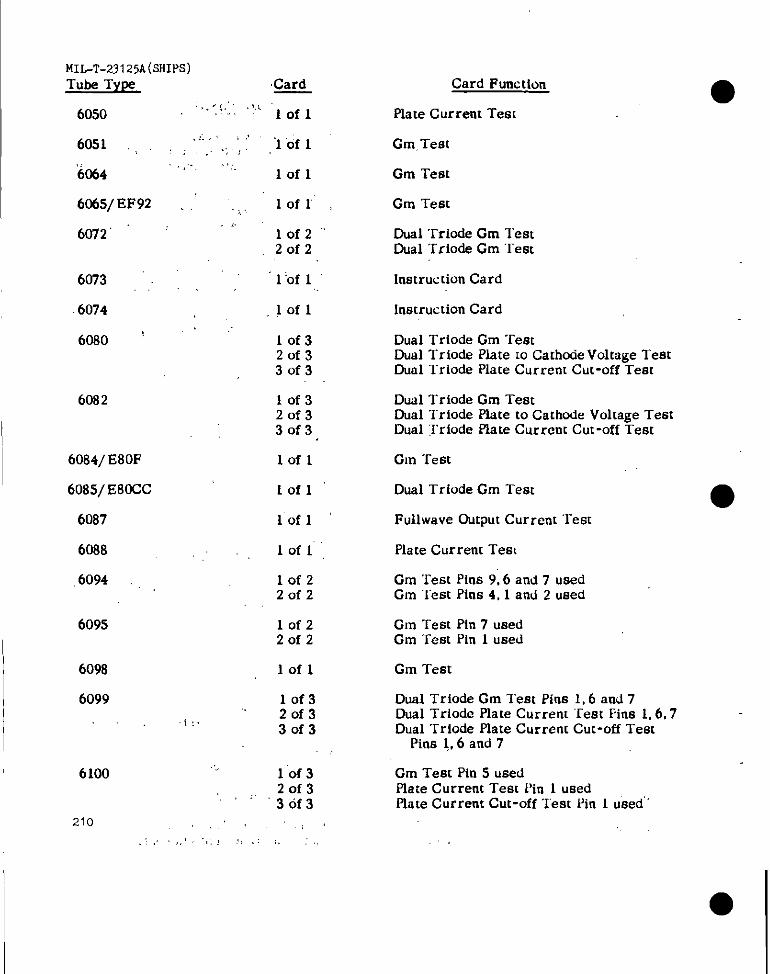
MIL-T-231 25A(SHIPS)
Tube TYP3 Card:.., ’’. ~,L-,!. lofl6050
6051 .,
6%4
6%5/ EF92
6072”
6073
.6074
6080 ‘
6082
6084/ E80F
6085/ E8CCC
6087
6088
.6094
6095
6098
6099
<.
,..
1:.
,,,’lofl... ;
,.,1011
,,. lofr.?
lof2°2012,,
1‘of 1
.1011
10f320133of3
10f3201330f3
lofl
1011
lofl
1011,
Iofz2of2
lofz20f2
lofl
10f320f330f3
6100
210.!,
10f320f3.,.3of3
,, .,:,,,, ,;,
Card Function
Plate Current Tes[
Gm,Test
Cm Test
Cm Test
Dual ‘rriode Cm TestDual Triode Cm “l-em
Instruc [ion Card
Instruction Card
Dual Triode Cm TestDual Triods Plate 10Cathtie Voltage TestDual ‘Triode Plate Current Cut-off Test
Dual Trio& Cm TestDual Triode Plate to Cathode Voltage TestDual :Iriode Plate Current Cut-off Test
Gm Test
Dual Triode Cm Test
Fullwave Gutput Current Test
Plate Current Test
Cm Test Pins 9,6 and 7 usedCm “lest Pins 4, 1 and 2 used
Cm Test Pin 7 usedCm “I_estPin 1 used
Cm Test
Dual Triode Cm Teat Pins 1,6 and 7Dual Triode Plate Current ‘Test Fins 1,6,7Dual Triode Plate Current Cut-off Test
Pins 1,6 and 7
Cm Test Pin 5 usedPlate Current Test Pin 1 usedPlate Current Cut-off Test Pin 1 uked”’
●
..=
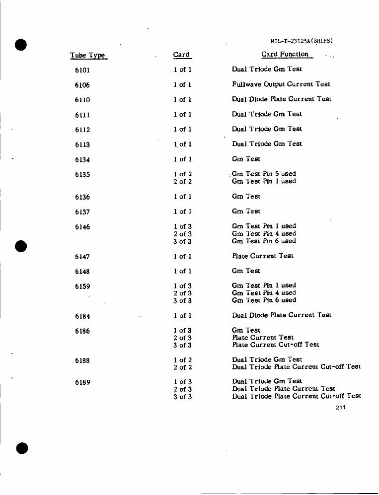
1.
Tube Type
6101
6106
6110
6111
6112
6113
6134
6135
6136
6137
6146
6147
6148
6159
6184
6186
6188
6189
Card
lofl
Iofl
lofl
lofl
lofl
I.of 1
iofl
10f220f2
lofl
Iofl
10f320f330f3
Iofl
lofl
10f320f330f3
lofl
10f32of330f3
lofz20f2
10f320f33of3
MIL-T-23 125A(:HIpS)
Card Function ,,
Dusl Triodc Cm Test
FuNwave Output Current Test
Dual Diode Plate Current Test
Dual Triode Gm Test
D.Ial Triode Cm Test
Dual Triode Cm Test
Cm Test
,Gm Teat Pin 5 usedGm Test Pin 1 used
Gm Teat
Gm Test
Gm Test Pin 1 usedGm Test Pin 4 usedGm Test Pin 6 used
Plate Current Test
Cm Teat
Cm Test Pin 1 usedGm Test Pin 4 usedCm Test Pin 6 used
Dual Diode Plate Current Test
Gm TeatPlate Current TestPlate Current Cut-off Teat
Dual Triode Gm TestDual Triode Plate Current Cut-off Test
Dual Triode Cm Teat@i l“riode Plate Current TestDual Trinde Plate Current Cut-off Test
211
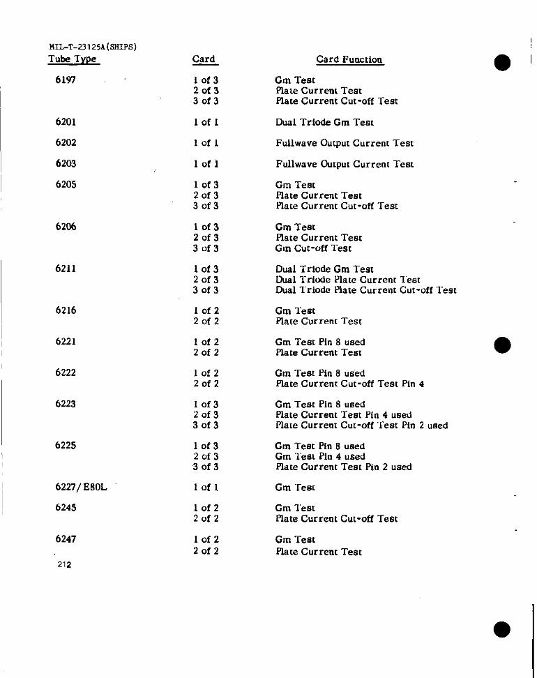
MIL-T-23 125A(SHIPS)
Tube Type
6197
6201
6202
6203
6205
6206
6211
6216
6221
6222
6223
6225
6227/ E80L
6245
6247
212
Card
10f32of33of3
lofl
lofl
lofl
lof320f33of3
lof32of33of3
lof32of330f3
lof22of2
lofz2of2
lof22of2
10f32of330f3
lof32of3‘3of 3
lofl
10f22of2
lofz2of2
Card Function
Cm TestPlate Current TestPlate Current Cut-off Test
Dual Triode Cm Test
Fullwave Dutput Current Test
Fullwave Output Current Test
Cm TestPlate Current TeatPlate Current Cut-off Test
Cm TestPlate Current TestGm Cut-off Test
Dual Triode Cm TestDual Triode Plate Current lestD@ T’rb& Piate Current Cut-off Test
Cm TestPlate Current Test
Gm Test Pin 8 usedPlate Current Teat
Cm Test Pin 8 usedPiate Current Cut-off Test Pin 4
Gm Test i% 8 usedPlate Current Test Pin 4 usedPlate Current Cut-off ‘rest Pin 2 used
Gm Test pin 8 usedCm lest Pin 4 usedElate Current Test Pin 2 used
Cm Test
Gm TestPlate Current Cut-off Test
Cm “restplate Current Test
● I
●
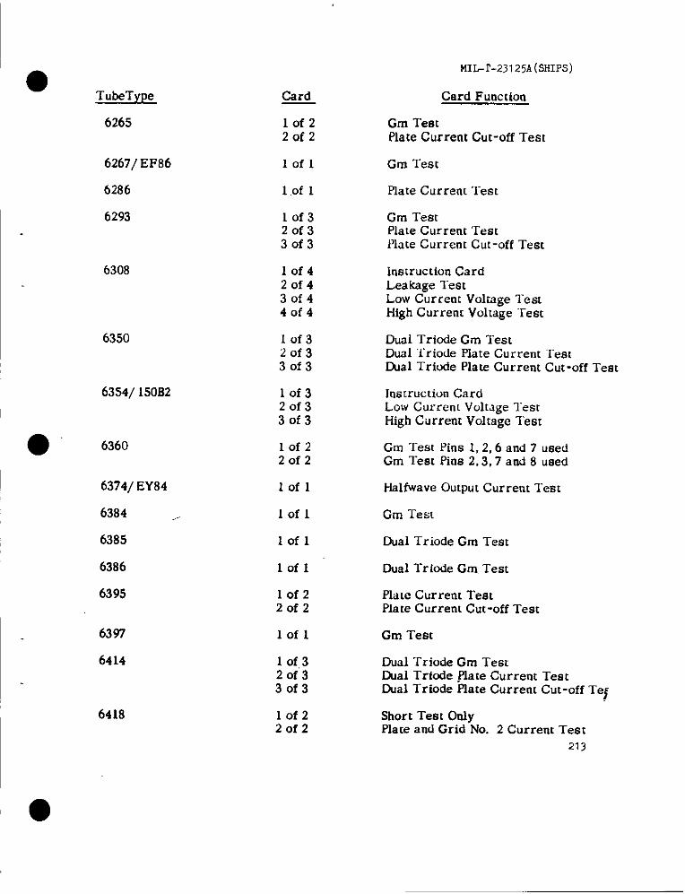
●TukType
6265
6267/EF86
6286
6293
6308
6350
6354/150B2
6360
6374/EY84
6384 ,.
6385
6386
6395
6397
6414
6418
card
lofzZofz
lofl
1 .Of I
lof32of330f3
10f42of430f440f4
lof320f330f3
10f32of330f3
lofzZofz
Iofl
lofl
lofl
lofl
lofzZofz
lofl
1 of,320f33of3
10f2Zofz
MI&r-23 125A(SHIPS)
Card Function
Gm TestPlate Current Cut-off Test
Gm Test
Plate Current Test
Gm TestPlate Current ‘IeatPlate Current Cut-off Test
instruction CardLeakage TestLow Current Voltage TeatHigh Current Voltage “rest
Dual Triode Gm TestDual Triode Piate Current lestthal Tricde Plate Current Cut-off Test
Instruction CardLow Currenl Voltage TestHigh Current Voltage Test
Gm ‘rest Pins 1,2,6 and 7 usedGm TestPine2,3,7and8 used
Halfivave Output Current Test
Gm Test
Dual l-riode Gm Test
Dual Triode Gm.Test
Plate Current TestPlate Current Cut -off Test
Gm Test
Oual ‘rriode Gm TestDual Trfode .Hate Current TestDual Triode Piate Current Cut-off TeJ
Short Test OrdyPlate and Grid No. 2 Current Test
213
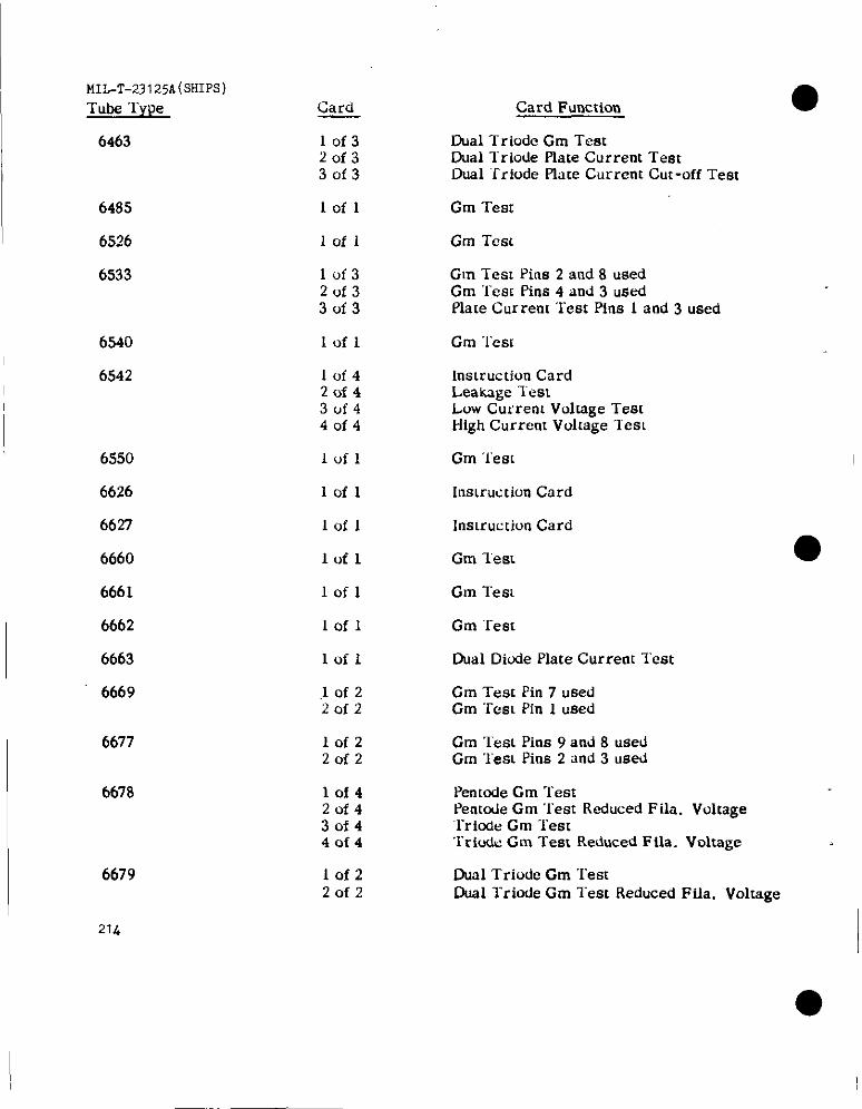
MII.-T-23125A(SHIPS)
Tubs Type
6463
6485
6526
6540
6542
6550
6626
6627
6660
6661
6662
6663
6669
6677
6678
6679
21L
Card
lof320f330f3
lofl
lofl
lof320133of3
lofl
lclf42of43uf440f4
lofl
1011
lofl
lofl
Iofl
1011
,1of220f2
101220f2
10142of430f44014
lof220f2
Card Function
Dual l-riode Gm TestDual l“riode Plate Current TestDual ‘Trlode Plate Current Cut-off Test
Cm “1’est
Cm Test
Gm Test Pins 2 and 8 usedCm “rest Pins 4 and 3 usedPlste Current “rest Pins 1 and 3 used
Gm “lest
Instruction CardLeakage lestLow Current Voltage TestHigh Current Voltage les[
Cm ‘lest
Insmmticm Card
instruc tiun Card
Gm lest
Gm Test
Cm Test
Dual Diode Plate Current Test
Gm Test Pin 7 usedGm “rest Pin 1 used
Cm ~esL Pins 9 and 8 usedGm “leSLPins 2 and 3 used
Penmde Cm TestPentude Gm Test Reduced F ikr. Voltage‘Triode Cm Test“l-riudeGm ‘i-est Reduced F fla. Voltage
Dual TrioLie Gm “rest~al Triode Gm Test Reduced Fiia. Voltage
I

MILT-23I25A(SHIPS)
Card Function
Dual Triode Cm “featDual Triode Cm Teat Reduced Fila. Voltsge
● Tube ‘1’ype
6680
Card
lofz20f2
6631
6686/E81L
Lofl Dual Triode Cm Teat
10f220f2
Cm Test Pin 6 usedPlate Current Teat Pin 1 used
Piste Current “1ef3tPlate Current Cut-off Teat Pin 1 usedpk?[e current Cut-off ‘lest pin ? u8ed
Cm ‘restPlate Current Test
Cm Test
6687/ E91H 10f32of330f3
6688/ E180F IofzZofz
6689/E83F
6754
6761
Iofl
Iofl Dual Ftdlwave Output Current Test
10f220f2
Gm ‘1’estPins 6,8 usedPlate Current “rest Pins 1,3 used
Cm “TeatPlateCurrent‘TeatplateCurrent Cut-off Test
Cm TestPlace Current ‘lestPlace Current Cut-off Tes[
lof32of33of3
lof32of330f3
6829 10f320f33of3
Dual Triode Gm ‘IestDual Triode Plate Cur rem TestDual Triode Plate Current Cut-off Test
Dual Triode Cm I“est~al “I”riode Plate Current TestDual l’riode Plate Current Cut-off Test
Cm “rest Pin 6,9 usedPlate Current “1est Pins 1,4 usedPlate Current Cut-off Test Pins 1,4 ufjed
6832 10f32of33of3
6877 10f320f330f3
6883 10f320f3
..! “’”30f3
Cm ‘rest Pin 1 usedCm “TestPin 4 usedCm Teat Pin 6 used
Plate “Current Test Diode No. 1:Plate Current Test Diode No. 2
215
5887 lof2Zofz
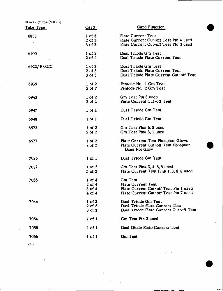
Card
MIL-T-23125A(SHIPs)
Card Function ●Piate Current TestPiate Current Cut-off Test Pin 4 usedPlate Current Cut-off Test Pin 3 used
Dual Triode Gm TestDual Triode Plate Current Test
Tube Type
6888 10f32of33of3
6900
6922/ E88CC
lof220f2
lof320f330f3
Dual Triode Gm TestDual Trio& Plate Current TeatDual Triode Plate Current Cut-off Test
Pentode No. 1 Gm TestPentode No. 2 Gm Teat
6939 lof22of2
Gm Teat Pin 8 usedPlate Current Cut-off Test
6943 10f220f2
6947
6948
6973
lofl Dual Triode Gm Test
Dual T riode Gm Teat
Gm Test Pins 6,8 usedGm Test Pfns 3,1 used
lofl
10f220f2
6977 lof220f2
Plate Current Test F?rosphorGlowsPlate Current Cut-off lest Phosphor
Does Not Glow a
7025
7027
Dual Triode Gm Test
Gm Test Pins 3,4,5,8 usedPlate Current Test Pins 1,3,6,8 used
Gm TestPlate Current TestPlate Current Cut-off Test Pin 1 usedPlate Current Cut-off Test Pin 7 used
lofl
I
10f22of2
lof420f43of440f4
7044 10f32of330f3
Dual Trio& Gm TestDual l-ride Plate Current TeatDual Trkrde Plate Current Cut-off Test
7054
7055
lofl Cm Test Pin 3 used
lofl Dual Dicde Plate Current Test
lofl Gm Test
216
●
✍✍
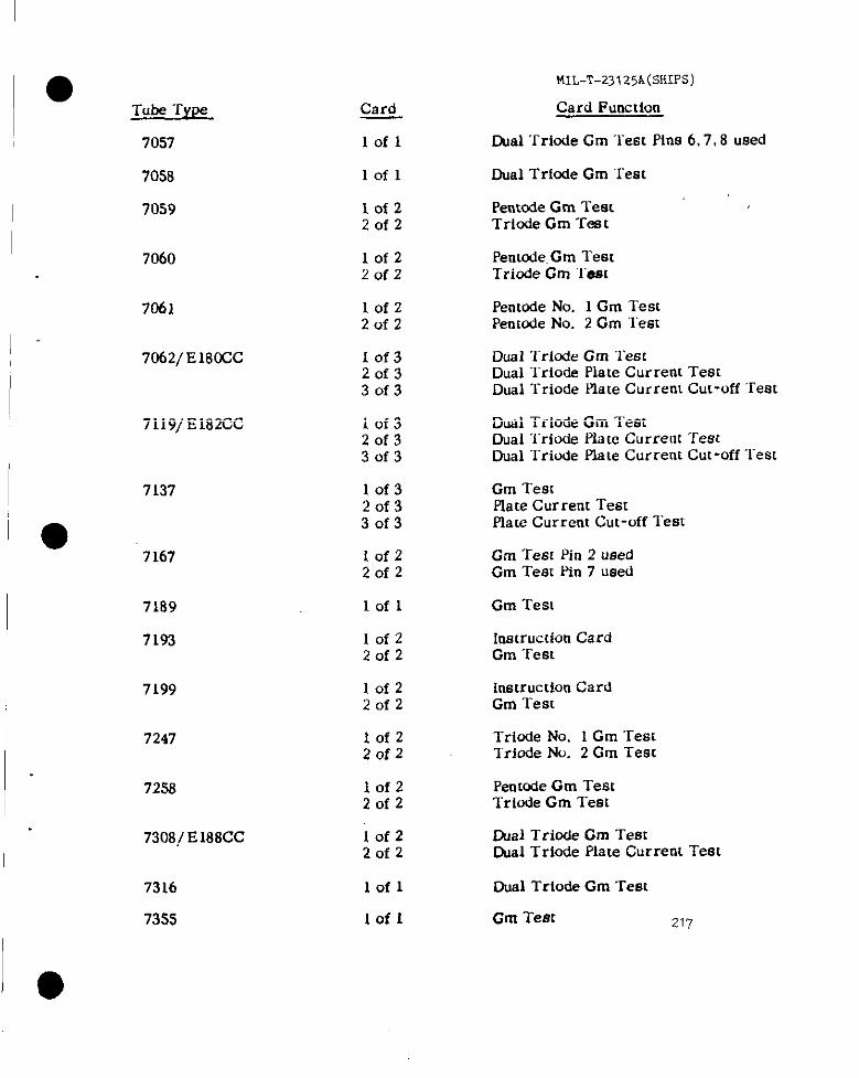
m,-T-231 25A (SHIPS)
Card Function
IAal ‘rriode Gm Test Pins 6,7,8 used
●Tube TYP.S
70s7
7058
70s9
Card
Iofl
lofl Dual Tricsfe Gm Teat
Pentode Gm TestTriode Gm Test
lofzZofz
Pentode. Gm Teal“riode Gm “l-em
Pentode No. 1 Gm TestPemode No. 2 Gm ‘Test
7060 lofz20f2
lof2Zofz
10f32of330f3
7061
7062/ E180CC Dual ‘I”riodeGm TestDual Triode Plate Current TestDual l“riode Plate Current Cut-off Test
Dual Triode Gm TestDUal“friOde plate Current TestDual Triode Piate Current Cut-off ‘l”est
7119/ E182CC 10f320f330f3
10f320f33of3
i0f220f2
Cm TestPiate Current TestPiate Current Cut-off Test
7137
7167 Gm Test Pin 2 usedGm Teat Pin 7 used
7189
7193
lofl Gm Test
Instruction CardGm Teat
10f220f2
lofz2of2
10f220f2
Instruction CardGm Test
Triode No. 1 Gm ‘restTriode No. 2 Gm Test
7199
7247
7258 Penmde Gm TeatTriode Gm Test
lhal Triode Gm Tem~al Triode Piate Current Test
lofz20f2
7308/ E188CC 10f220f2
Dual Triode Gm Test
Cm Teec
7316
73ss
iofl
lofl 217
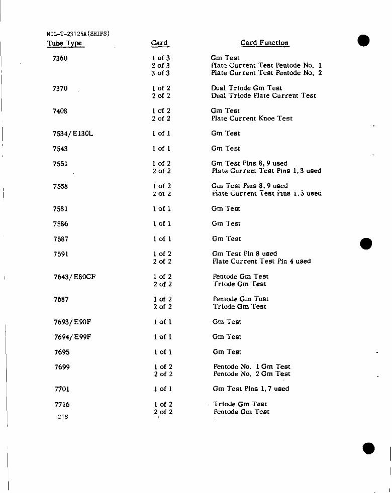
MIL-T-23125A(SIIIPS)
Tube TYW Card Card Function
7360 10f320f330f3
Gm TestRate Current Test Pentnde No. 1Plate Cur rent Test PentOde No, 2
10f22of2
Cual Triode Gm TestDual ‘Mode Plate Current Test
7370
7408 Iofz20f2
Gm TestPlate Current Knee Test
7534/E 130L
7543
7551
lofl Gm Test
lofl Gm Test
Gm Test Pins 8, 9 usedl% te Current Test Pins 1.3 used
10f220f2
7558 10f22of2
Gm “TestPins 8,9 usedPlate Current Test Ptns 1,3 used
7581
7586
7587
7591
lofl Gm Test
lofl Gm Test
lofl Gm Test
Gm Teat Pin 8 usedPlate Current Test Pin 4 used
10f220f2
7643/ E8CCF lofz20f2
Pentode Gm Test“Sriode Gm Test
7687 10f220f2
Pent&e Gm TestTricrde Gm Test
7693/E90F
7694/E99F
7695
7699
lofl Gm Tem
Iofl Gm Teat
Gm Teatlofl
10f220f2
Pentode No. 1Gm TestPenmde No. 2 Gm Test
Gm Test Pins 1,7 used7701
7716
218
Iofl
10f220f2,.
Tricde Gm TeatPentode Gm Teat

●Tube TY@?
7717
7719
MIL-T-23125A(sHIps)
Card Function
Gm Test
Card
lofl
10f220f2
Gm Test Pins 6,7 usedPlate Current Test Pins 1,2 used
Gm Test Pin 1 used
~
7722/E280F
7724
lofl
Tricde Gm TestDusl Diode Piste Current Test
Cual I’riode Cm Test
Dual Triode Gm Test
lof220f2
lofl
lofl
lofl
Iofz2of2
I 7728
7729
7730
7731
Dual Trlode Gm Test
Penmde Gm TestTriode Gm Test
Gm “rest7732
7733
7734
lofl
lofl Gm Test
10f420f43of44of4
lofz20f2
Pentode Gm TestTriocle Gm TentTriude Plste Current Test“I-ride Plate Current Cut-off Test
Gm Test Pin 3 usedplate Current Test Pin 1 used
7737/ EM6F
7754
7759
lofl Gm Test
lofz20f2
Iofl
‘lof 1
Dual Triode Gm TestDusl TriOde Plate Current Cut-off Test
7760
7761
7762
Duel Triode Gm Test
Gm Test
10f320f330f3
Gm Test Pin 8 usedPlate Current Test Pin 4 usedplate Current Cut-off Test
7788/ E810F 10f22of2
Gm “restPlate Current Test
219
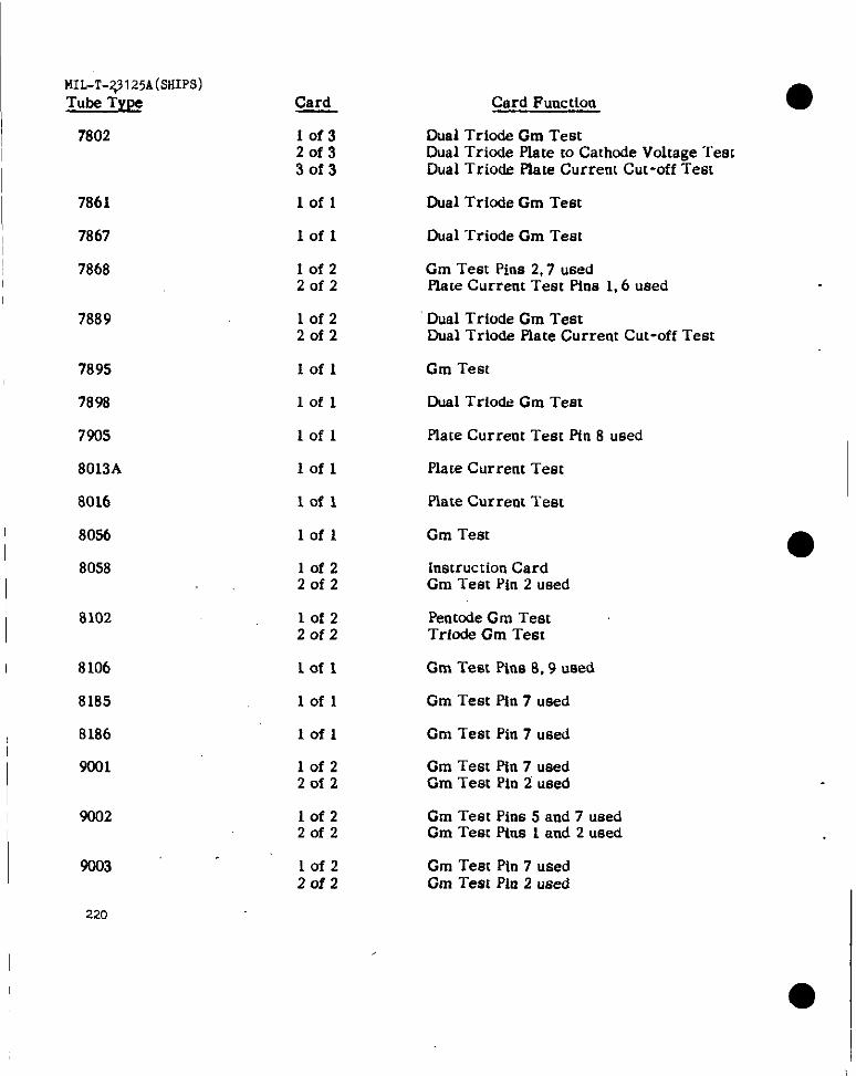
I MIL-T-~125A(SIUPS)
I
Tube Type
7802
7861
7867
7868
7889
7895
7898
7905
8013A
8016
8056
8058
8102
8106
8185
8186
9001
9002
9003 “
Card
lof320f33of3
Iofl
Iofl
IofzZofz
lofz2of2
Iofl
lofl
Iofl
lofl
lofl
lofl
lofzZofz
lofz
Zofz
Lofl
lofl
Iofl
lofz20f2
IofzZofz
Iofz2of2
Card Functioo
Dual Triode Gm TestDual Triode Plate to Cathode Voltage ‘restDual Trio& Piate Current Cut-off Test
Dual Triode Gm Teat
Dual Triode Gm Teat
Cm Test Pina 2,7 usedPlate Current Test Pins 1,6 used
Dual Triode Gm TestDUal‘rrio& Plate Current Cut-off Test
Gm Teat
Dual Triode Gm Test
Plate Curreot Teat Pin 8 used
Plate Current Test
Piate Current ‘rest
Gm Test
Instruction CardGm Test Pin 2 used
Pent@deCm TeatTriode Gm Test
Gm Test PiIIs 8,9 used
Gm Tetx Pin 7 used
Gm Test Pin 7 used
Cm Test Pin 7 usedCm Test Pin 2 ueed
Cm Teat Pins 5 and 7 usedGm Test Pius 1 and 2 used
Gm Test Pln 7 usedGm Test Pin 2 used
●
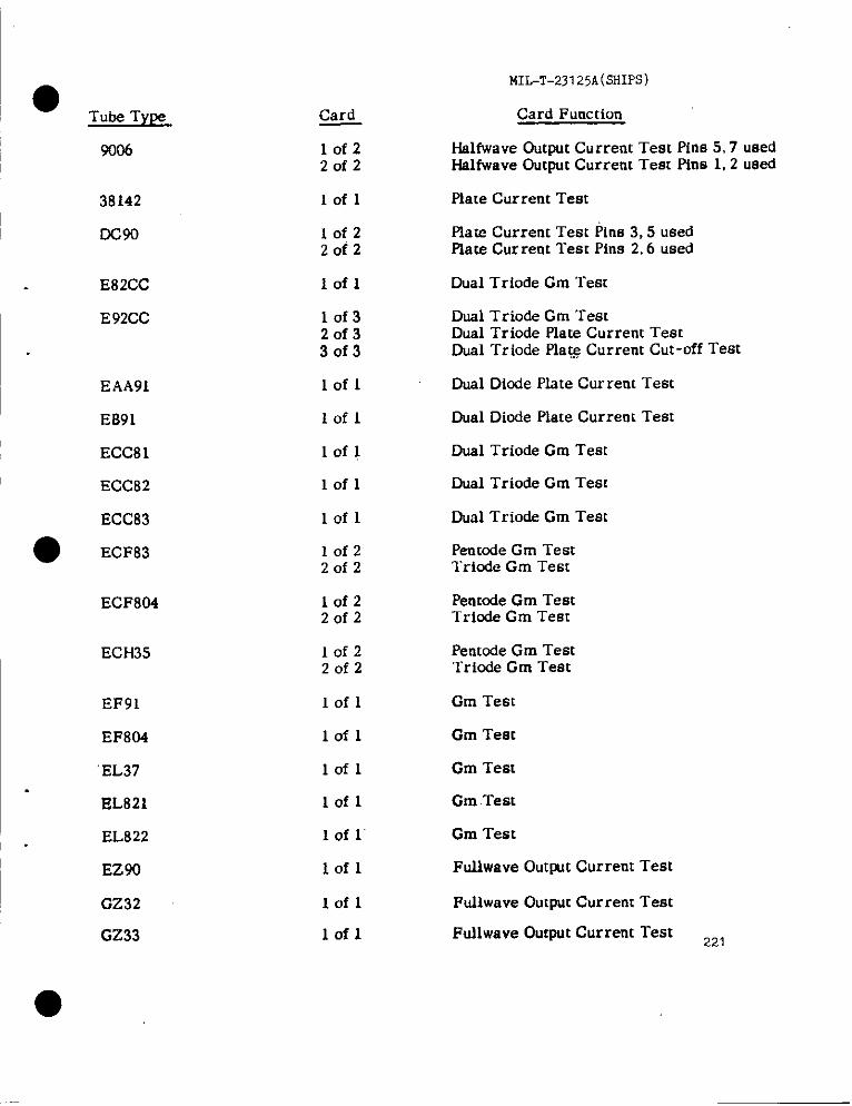
Tube TytM
9006
38142
DC90
E82CC
E 92CC
EAA91
EB91
ECC81
ECC82
ECC83
ECF83
ECF804
ECH35
EF91
EF804
EL37
EL821
EL822
EZ90
GZ32
GZ33
Card
lofzZofz
Iofl
lofzZofz
lofl
10f320f33of3
Iofl
Iofl
lofl
lofl
lofl
lofzZofz
IofzZofz
lofzZofz
Iofl
lofl
lofl
lofl
lof 1’
Iofl
lofl
lofl
MIL-T-23125A(SHIPS)
Card Function
Halfwave Output Current Test Pins 5,7 usedHaifwave Output Current Teat Pins 1,2 used
Plate Current Test
flaw Current Test Pins 3,5 usedPlateCurrent Teat Pins 2,6 used
Dual Triode Cm Test
Dual Triode Gm TestDual Triode Piate Current TestDual Triode Piatg Current Cut-off Test
Dual Diode Plate Current Test
Oual Diode Plate Current Test
Dual Triode Cm Test
Dual Triode Gm Test
Duai Triode Cm Test
Pentcde Gm TeatTriode Gm Teat
PentOdeGm TestTriode Gm Teat
Pentode Gm TeatTriode Gm Test
Gm Test
Cm Test
Gm Test
Cm Test
Gm Test
FuUwave Output Current Test
Fullwave Output Current Test
Fuilwave Output Current Test 221
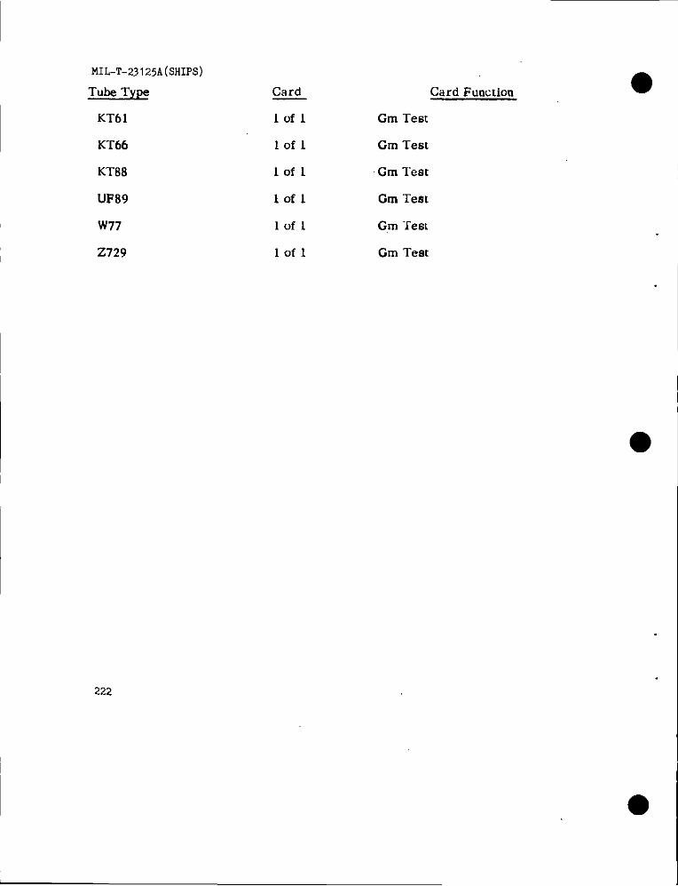
MIL-T-231 25A(SHIPS)
Tube Type
KT61
Kr66
KT88
UF89
W77
2729
222
Card
lofl
lofl
lofl
lofl
Iofl
lofl
Card Function
Gm Test
Cm Test
Cm Test
Cm Test
Gm “rest
Cm Test
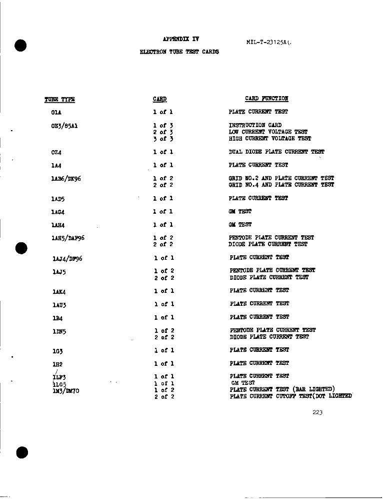
APFsliDxIv
ELECTRONTOM - CARD9
MIL-T-23125A(.
g
lofl
CARD FGlicTI021
PLATEcuRREnTm
TOBETYF3
Ou
0E3/85Al 10f320f33of3
12isTRU01’IOMCARD2.UVC02UIEBTVOLTAGETE9THIGHWRREl?l VO~AGE TEST
024
1A4
lAB6/D296
lefl DUALDIODDPLATE CURREIiTTEST
lofl PLATE CURRE2?2TEST
10f22of2
WIID2i0.2 AND PLATE C~ TESTGRIDNO.4MC PLATECCRREHTTFST
lAD5
lAG4
lofl PLATE CUREE?3TTlK42
lofl QfTEsT
W lofl GM TEST
IAE5/DAP96
●lAJ4/DP96
10f220f2
PDWK)DEPLATECOI12RfTTESTDIODEPLATECOER142WT=
lofl PLATDcU2REm T1292
1AJ5 10f220f2
lofl
lofl
PEI?NJDBPLATECD2BENI’TD9TDIODEPLATE CURRE6TT!Ml’
PLATE COREE2?ITkWrx
1AU5
2.B4
lDn5
PLATEcoBREl?rTEST
lofl PLATECmlrm?rTEST
10f220f2
lofl
lofl
Pmrom P2ATEccriBxmTESTDIODEPLATE CUIREliT=
PLATEcoBREl?rTE9TlG3.
P2ATBWFfU2?lTESTlE2
i&lumlo
lofl PLATEcuRm2iTTESTG$!TES2PLATEcwRRR?r‘imT (BARLIml’Em)PLATE C~ CCTOFPT2ST(IDT LIGETED
lofl10f220f2
223
—

MIL-T-23125A(SHIPS)
TUEE TYPB
12?2
lR@l’71
lS2A/DY81
1u6
1v6
lv15
2AF4
2B3
2s4
2B7
2BE4
2CW4
2LX5
2DS4
2D24
2E5
2E52
2E>6
2E41
2s42
lof220f2
10?220f2
lofz20f2
lofl
lofl
lot-l
10f320f53of3
10f220f2
lofl
lofl
lofl
Iofl
lofl
10f22of2
lofl
lofl
10f220f2
Iofz2 of 2.
CMD POXCTIOh
PLATE CURSmTTs9P
PLATS cUmxl?’r TEST (RAE LIQI..””,PU17i C~ cW20PPT131 (101 LIGSTBD)
PLATEcoRRmiTTc?9P
PLATS coRRP2fPTPSrP2.A~, cSID 2, GRID 3 ~ 12BID3
cuRR22mTE.?P
PEiiTODEPLATS C~ TESlTRIODEPLATE cURSEm Tmr
PLATEcOB2G2iTTESTPLATE TO CATSODEVOLTAGETESTPLi171CORKEt?pCOT(X9 T~
Fml’ODRGHTEsTDUALDIODEPLAl% C~ TEST
GMTEST
CMTEST
GMTEST
an TEsT
GMTSST
INDICATOREVE OP~INDICATOREYE SRW2
PMT% C~ TSGT
PUm C~ TE.T
PECVTOD!IPLATS CUSRERI’TS9PDIODEPLATECOSRE2WTEST
PEtilWE PLATE cu2frmTTzwDIODEPLATE C~ =
224
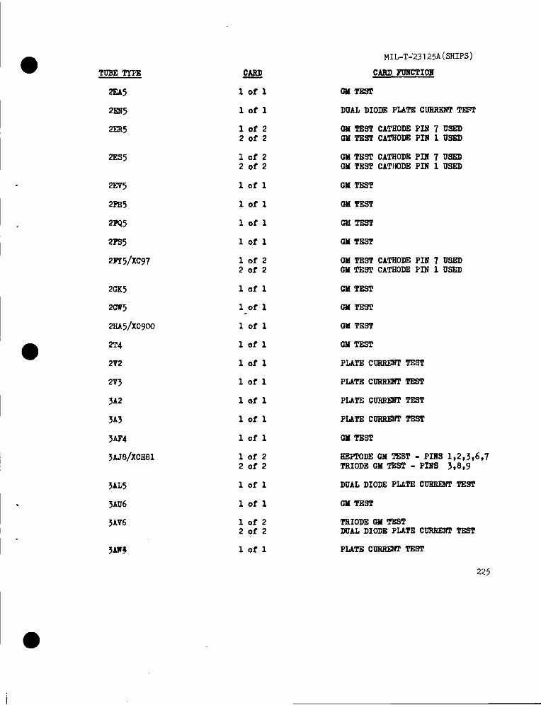
I ● TUSD TYPE
mA5
2~5
2ER5
2ES5
2sv5
2m5
2N15
2PS5
2~5/XC97
20s5
20W5
2HA5/XC900
2T4
2V2
2V3
3.A2
>A3
xlP4
3AJ8/XCH81
3AL5
3AU6
3AV6
QARIJ
lofl
lofl
lofz20f2
10f220f2
lofl
lofl
lofl
lofl
10f220f2
lofl
lofl
lofl
lofl
lofl
lofl
lofl
lofl
lofl
lofz20f2
lofl
lofl
10f22er2
MIL-T-’23125A(sHIPs)
CARD PC2iCTIOS
0MT292
DUAL DIOIEPLATECUTIREWTTEST
OIATESTCATHODEPIU 7 US3DOM TESTCATSODEPIN 1 USED
CM TDST CATSODEPIl!7 USDOM TESTCATHODEPXH 1 U9ED
GM TEST
OM TEST
OIATEST
W TEST
OM TESTCATSODEPIil7 DSRCOH TEST CATHODEPIN 1 U~
OM TEST
OM TEST
OM TEST
CM TSST
PLATScusREm TSST
PLATSCURRWT ~T
PLATSCossm T2sT
PLAT2ccrlRmffTEST
CM TEST
EEPTODEGM TsST - PIIIS1,2,J,6,7TSIODEOM TOST - P121S3,8,9
DUALDIODEPLATECUSEENTTIWl
on TEST
TRIODEW TESTDCAL DIODEPLATECCRBENTTWT
I ●
lofl PLATEcoRB12r2TSST
225
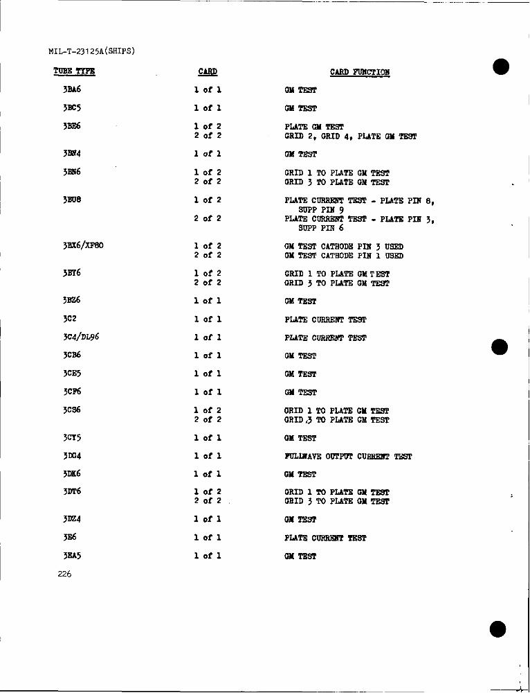
MIL-T-23125A(SHIPS)
TOBST2P2
3SA6
5SC5
3BE6
W!2
lofl
CARD PIJXCTIC.N
ml mm
lofl ON TEST
lofz20f2
lofl
lofz2of2
PLATE ONmmGRID 2, GRID 4, PLATEGM -
JSE4
3R2i6 CRID 1 TO PI.ATS GMTEWoRID 3 TO PLATEGM TEST
lof2 PIATScDRFOmPmm . PLATEPIN 8,SUPPPIN 9
PLATE CORREBITEST - PLATE PIK ~,SOPPPm 6
20f2
32ix6/xF80 10f220f2
10f2Zofz
GMTSSTCATHODEPIx 3 USEDGMTESTCATHODEFIM1 USED
jSY6 GRID 1 TO PLATE OMTEST13RID3 TOPLATS13MTE92
5s26
3C2
3C41DW6
Jcl%
3CE5
}CF6
TCS6
lofl ON TRW
lofl PLATEcuRsEm mm
lofl
lofl
lofl
PU’2E C~ TEsT
GM TssT
ON TEST
lofl w TEST
lof220f2
13RID1 TO PLATE CMTESPGRID,3TO PLATSON TEST
3cY5
5tc4
3DK6
3uf6
lofl
lofl
OM TEST
FDLINAVEO~POT CURREMITEST
lofl OMTEST
lofz20f2
GRID 12’0PLATSOM TE92OSID j TO PLATS OHTEST
3m4
JE6
3EA5
226
lefl 0MTB9P
lofl PLATEcosRmrr‘rNsT
lofl oHmsT
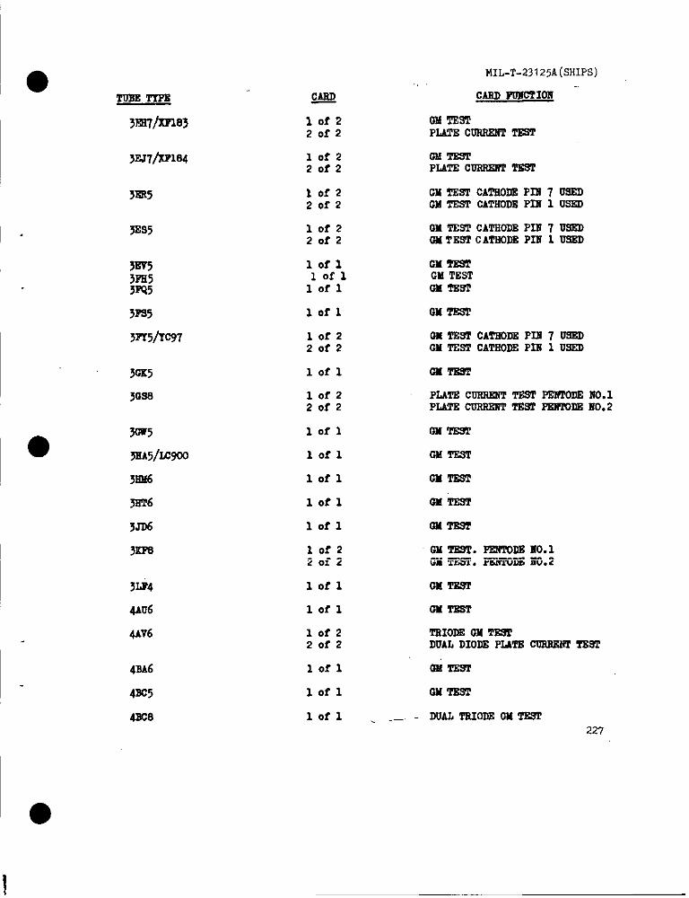
Tum T’fP2
3Ri?/xP183
3EJ7/xF184
yKR5
5ES5
3BV5;Fl&
3PS5
Wv5/Tc97
3oK5
31xl.9
W5
5EA5/Lc900
3BM
5ST6
3Jr6
3iiPa
3ti4
4AU6
4AV6
4B.A6
4Bc5
4248
10f220f2
10f220f2
lofz20f2
lofz20f2
lofllofllofl
lofl
10f22of2
lofl
10f220f2
lofl
lofl
lofl
lofl
lofl
10f22of2
lofl
lofl
10f220f2
lofl
lofl
lofl
MIL-T-23I25A(SHIPS)
cm 202icTIOl!-
OblTESTPLATEC0212XW2TEST
oM’rEmPLATEcuRRE2f2TEST
CM TE2T CATHODEPDi7 OSEDGM TEST CATSODEPIE 1 USED
W T222TCATSODEPIN7 Di%Dw TESTCATHODSPIE 1 USED
CMTESTOMTEST12M~sT
w TEST
OXTE91CATHODEPIE 7 USEDOHTSS2CATSODEP12i1 USXD
Oum
PLATEcuRsmTTEsTPm?roDEIio.1PLATEcossmiTTE9TFEr?20DEE002
Ommm
GMTEST
OMTEST
GMTEST
QH’mlsr
GMTB9T.PE2iTQD2Ho.1m TEST.PK!?roDElm.2
OMT12m
GMTEST
17110~m eDUALDIODEHATSCOFOWNTT2W
onTEm
GM‘lzsT
DUALTFUODEOMTE92227

MIL-T-Z125A(SSIPS)
TURETTPE
4B126
@.a/xc260
4SR6
4B98
4m
=
10f220f2
QRID2, GRID 4,8ndPL&TE‘W TESTPLATSGM TiW
lofzZofz
PmToDEG2JT2mTRIOI13GM H
10f220f2
GRID NO. 1 TO PIMP, CMT217113EID 2i0. S TU PLATE GM TEST
lofl DUALTRIODEGMl’EsT
10f220f2
PLATEcuRsE2trTmTPLATEPm 8 USEDPLATECQRRWf TP.STPINE PIR 3 USED
42X8
4B26
4s21
4Em
4CB6
@E3
4CS6
4cY5
4D=
4D26
4Dr6
4mi7m83
42J7/YFlo4
4EsR/xcc189
4EX6
4G225
228
,1of 1 DUALTRIODJ2GMTEST
GETliCIlofl
lofl DUALTRIODEGM~
lofl DUALTRIODEIX TEGT
lofl GilTEST
Iofl W mm
lot-z20f2
GRID 1 TO P2NT2GM TESTORID 3 TOPLATEORTEST
OM’ms’rIIlorl GM TEST
lorl w Twr
10f22of2
GRID1 TO PLATEG21TE9TGRID 3 TO PI-WEIX TRST
lofzZofz
CM TEShCATIIODiiPIR J USEDPLATSCORRD~TESLCATROD2PIE 1 USED
10f220f2
GM TE9&CATKODE-P2EJ USEDPLATSCURRR2iTT22?JI- CATIJ3DEP12 1 USEU
lofl DUAL TRIODEGM TEST
lofl
lofl GM mm
I
..-
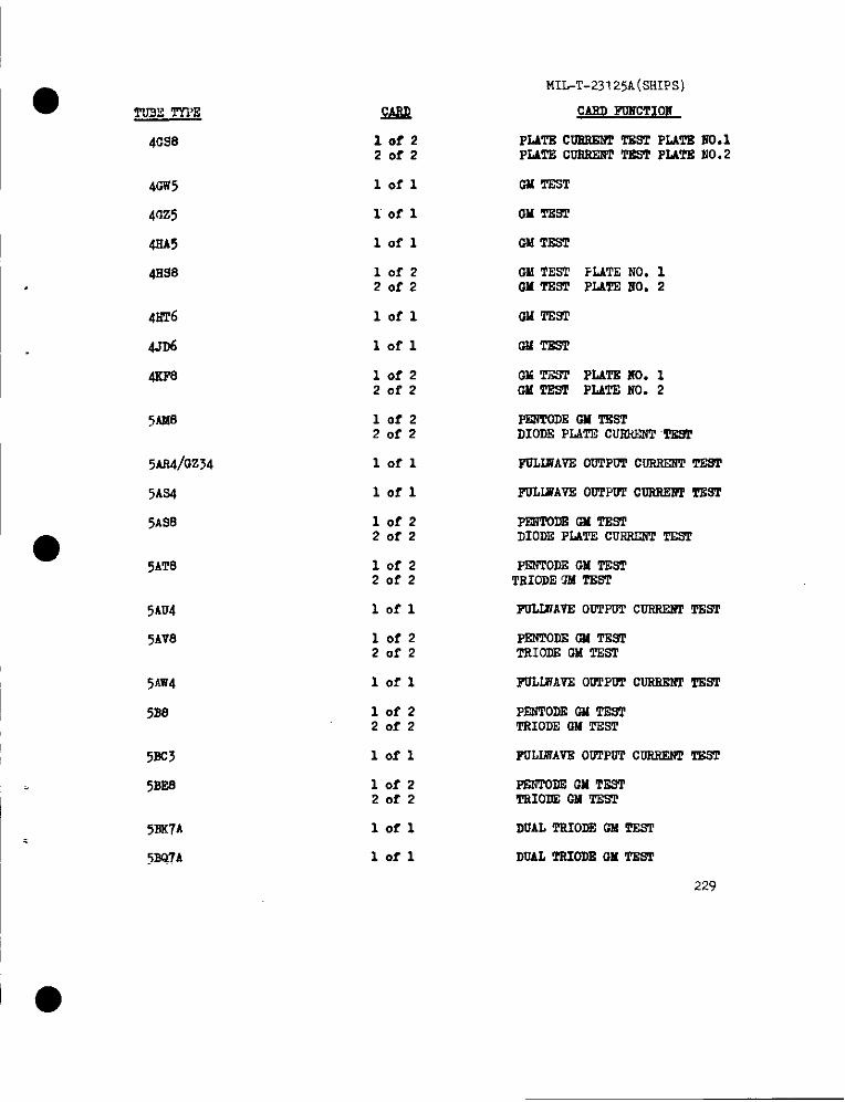
● TD3Z TYI’E
4CS8
MIGT-23125A(sHIPs)
CAKDPOliOTIONwPL4TS c02miW TEST PLATS m.1PLATE COS2W+TTDsT PLWE MO.2
lofzZofz
40W5
4az5
41M5
4sS8
41?T6
4JD6
4ZF8
lofl GM TEsT
lofl OM TEV2
lofl GM TEST
IofzZofz
OM TEST FLATENO. 1GMTDSTPLATD2i0.2
lofl GM mm
lofl CUTEST
lofzZofz
GM TZST PLATSHo. 1OMT2ST PLATENo. 2
lofzZofz
FmTom GM mmDIODEPLATECUSSENT‘~
5AM8
xs4/o’A34 lofl PUIJMAVS00TPOTC100tEWITRW
5AS4 lofl POLUPAVE00TW’PC0RSE2?lTZST
5.4s8 lofzZofz
PmToDz GHTEsTDIODEPLATECUSSEJWTIX?l
●5AT8 lofz
ZofzPIWTODEGM TEsTTBIODEGM TSST
5AU4
5AV8
lofl PULLWAVEO~POT CORSEIWTEST
lofzZofz
PENTODSm! TESTTSIODECM TEST
lofl
lofzZofz
FOLIHAVEOWPPOTCOSSE2f2T2WI5m14
5B8 PEWPODDGM ‘mm’TSIODEOM TEST
5E5
5B28
lofl POLWAV2 00TPOTCOSSPJWTEST
lofzZofz
PEmoDE GM mTEIOEAOM TEST
5sK7A
5SQ7A
lofl DUALTSIODEO!dTEST
lofl DOALTS2022BOX TZST
229
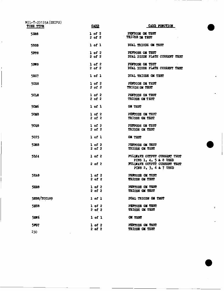
MI~T-23125A(SHIPS)T~ TIPS
Sma
gAJQ
lof220r2
PT2BTQDEOMTB82TRmm (x msT
5BS8
5sTe
lofl DUALTSIODZW TZST
10f22of2
10f220f2
FmToDzGMmmDUALDIOI!3PLATSCUSRS8TTEST
PES90DEOM TESTDUALDIODEPLATSCUSREW2TE92
5mIo
5BZ7
5CG8
lofl DUALTRIODBOM TZ9T
lofz20f2
PE2mms onTEST‘nrloDEw TEm
5C218 lofz2of2
PESTODEGM T2STT210DEGM TESI
lofl
10f220f2
w TzsT50M6
5CH8 Psm’ormOM ‘mmTRIODECM T2ST
5CQ8 10f220f2
PF2iYODEGM TESTTRIODEGM TE9T
5CZ5
5DS.9
lofl Gm!ms2
● I10f220f2
10f2
20f2
PmmDB GM TESTTSIODEGM TZS2
I51U4 P02MAVE oulTmCoss2m TEST
PIIisl,4,5&e usEDFM.IE’AV2OUTPVlCUSSSB’2TEW
P12fS2,3,6Lk7 USED
PZB20D20MTZSTmom OHT22m
5PM 10f220f2
5ES8 10f22of2
lofl
10f220f2
PElmDEoM!Pzsl!mIoD8GM TR?2
DoALT210DEw TIm52S8@189
5ED8 PmTomoMm29TTluoDEoMmm
5w6
5m7
230
0MTE%2lofl
10f220f2
FEtmDzon TzmTRIom w TES2
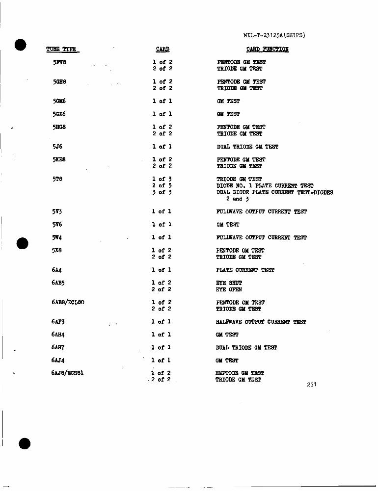
● Tum T’xm
MIL-T-23125A(sHIPs)
5~8 lofz20f2
mDE au mmTsIODSGM TIST
50E8 lofzZofz
PENToDEoMTEmTEIODEOM lZ9T
5cn6
50X6
52C8
lofl 0X T20T
10?1 OH TES’I
10r2Zofz
lofl
lofz20f2
PKsTODEGM TEOTTsIODEOH T2ST
5J6
5xm
DUALTSIODXCM TSSP
EmTom GM TEEITsIODEW TEST
5T8 10f3Zof>30f5
T210DEOM TEsTDIODEMO. 1 PLATEC~ TXUIDUALDIODEPLATECORREIWTEST-DIODkE
2~d3
5V5
5Y6
lofl PULUVAVSODTP~ COSREIVTT?lVl
lofl GM TEsT
lofl FTLLWAVEOmPDT C_ TsST
10f220f2
PF27TODSOM TESTTRIODEGM TEST
6A4
6A25
lofl PIATScusF@lTTEST
lofzZofz
Er2s2uTm 0PF2J
6A28/2cL80 lofzZofz
PI12VIQDEGM TEST~IODE CM =
6AP3
6AH4
6AR7
6AJ4
6AJIA/ECE81
lofl KALHiAVE00TP02CU- TEST
lofl
lofl
lofl
w TD9’I
DUALTSIODEOM TE.?l
CIATE9T
lofz,20f2
EEW3D2 (m Tl?9TTSIODEGM mm
231
—
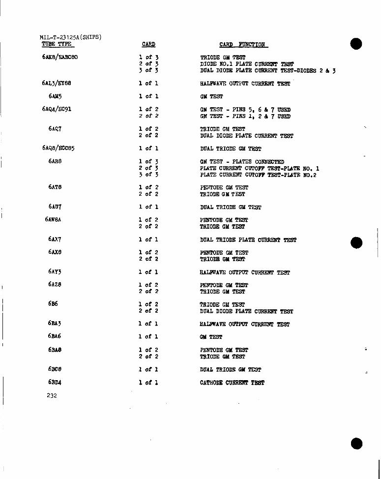
MIL-T-23125A(SHIPS)Tus2TrPE
6AK8/EAro30
6AL@88
6M15
6~Q4/Ec91
6AQ7
6AQ8/E12c85
6AH8
6AT8
6AU7
6m3A
6AX7
6AX8
6AY5
6AZ8
6s6
61M3
6SA6
6SA8
6m%
6BD4
232
Q&4
lof~20f3>0f3
lofl
lofl
lof2Zofz
10f220f2
lofl
10f3zof~~of~
10f2Zofz
lofl
10f220f2
lofl
lofz20f2
lofl
lofz20f2
lofz20f2
lofl
lofl
lofz20f2
lofl
lofl
s~ PDTfCTIOli
TRIODEw TESTD1ODE2?0.1PLATSCORRQ?TTESTDUALDIODSPLATECCRREW2TEST-DIODES2 & J
RALEWAVEOUTPCTCOP.RERIT13sT
ml TEST
GM TEST -PIlfS3,6h7US3!DGMTEST -P117S1,267 USED
TRIODECMTESTDUALDIODEPLATE CURREliTTEST
DUALTRIOD2CMTSST
CMTEST - PLA’I’W coifffmmPLATEcoRRRfr CWTOPPTSST-P2ATENo. 1PLVTEcoRRENrCOPOFPTEST-PLATENO.2
PENTODEGM TESTTRIODEGM TEST
DUALTHIODEGM TSST
PEBTOD13GM TESTTSIODECM TE91
IIUALTRIODEPLATsCORREliTTEST
PEN20DECMTESTTRIolmml TE9T
EALFWAVS00TPW2CCRRRWTEST
PSNTODSGMTESTTSIODEGM TE9T
TRIODEGklTESTDUALDIODEPL4TECDRRRITTEST
HAL2TAVE0U2FTT~ TEST
CM TEST
PERTODEGM T23TTRIOD2GM TEST
DUAL TRIODEGM TECT
CATHODECU= TEsT
● I
●
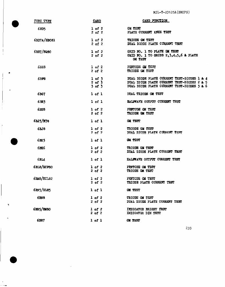
MIL-T-23 I 25A(SHIpS)
QruJ
@
2’OBETYPE
6BD5
CASDmm 0sI
10f220f2
GM mm’PLATEc22TUtEmSSzE TssT
61n7@Bc81 10f220f2
TSIODBGM TESlDUALDIODEPLATECURREliTT?39T
GRIDNO. 1 TOPLATSW TESTCS2DITO.1 TO0S2DS2,>,4,5,6 h PLATE
OHT2t711
PmToDEa TE9TTRIODECMTEST
DUALDIODEPLATSCOSSEIWTSST-DIODE91 h 4DUALDIODP,PLATECDSRSSTTB9T-DIODES2 A 5DUALDIODEPLATECORBXI?TTEST-DIODDS3 b 6
DUALTSIO16iGMTEST
SALIWAVSOWTPDTCOBSEtlTTE9T
6sE7/EQ80 lof220f2
6ss8
.
6Brn
lofzZofz
10f J20f330f3
6s07 lofl
6EU
6BS8
lofl
lofz20f2
PEmoDs 2s TmTTEIODSon ‘fEm
6SJ5/li78
6SJ8
lofl 012TB9T
TSIODEW TSSPDUALDIODEPLATEC~ TEST
OMTDST
TS20DSOH TESTDUALDIODEPL4TBCOFOWIT~
SALIWAVEOUTPOTCDRES2?ITE9T
PESTormw TESTTSIODECMTEST
lof22of2
lofl
10f220f2
● 6SS5
6ss6
6BL4
6BL8/SCF80
lofl
10f220f2
61?AdFXLJ32 10f2Zofz
PmTom m TESTTs20m PLATEc- TE9T
6BN5/E1435 lofl OMTSST
TRIODECM2!E.WDUALDIODEP2JTDCDFOWWTTS9T
IRDICATORBSIOSTTESTINDICATORDD.1TEST
0X9EST
233
6ss.9 10f220f2
,
6ss5/mO 10f220f2
6SS7 lafl
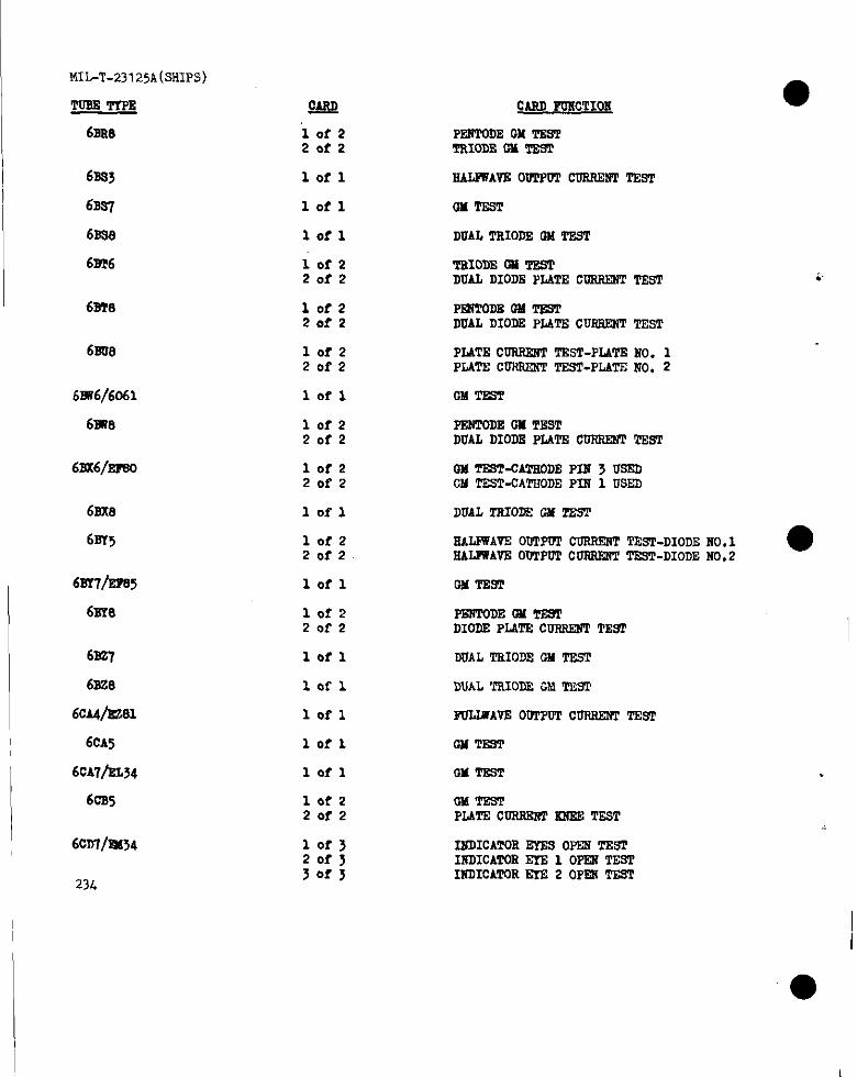
MIL-T-23125A(SHIPS)
TuBSTYPS
6ss8
6ss3
6BSI
6SSS
6m6
I 6BT8
6BU8
62w6/6061I
6m8
6Bs6/smo
62x8
6s?5
6BY7/EFS5
6BY8
6EZ7
6ss8
6CA4/ES81
6cA5
6cA7/BL54
6CB5
I6z2rf/sl#34
234
~
“1of 2Zofz
lofl
lofl
lofl
lofzZofz
lofz20f2
lofzZofz
lofl
lofz20f2
lofzZofz
lofl
lofzZofz
lofl
10f22ef2
lofl
lofl
lofl
lofl
lofl
lofz20f2
10f320f3j0f3
CAU PoNc’PIOE
PENTODECM TNSTTRIODEON TEST
NALITAVE0~~ ~ TEST
OMTDST
DUALTRIODEUN TEST
TSIODEOu TEsTDUAL DIODEPLATECDNIWITT2sT
P131’20DECN TESTDUALDIODSPIATECURRNNTTEST
PLATECURRENTTEsT-PIATENO. 1PIATSCURRiTNTTEST-PLATENO, 2
CM TPsT
PENTODEW TNSTDUALDIODSPLATECURN2fPTEST
GN TS9T-CATSODEPIN 3 USEDGMTESWCATSODEPIN 1 USED
DUALTRIODEOMTEST
SAIJWA?E00TPUPCORR12WTEST-DIODE110,1 ●RAJJWAVSOU1’POTCOPRENTTSST-DIODENO.2
GMmm
I%NTODEOMTE9TDIODNPLAT2 CURRE2?PTEW
DUALTRIODSONTEST
PULWAVEOU1’~ CURREt?TTDST
CMTEST
W TSsT
OMTESTPIATE CURRSRTSRESTEST
INDICATORINE9 OPENTES1’INDICATOREfE 1 OPRi TESTINDICATOREIE 2 OPRIT23T
I
–L.

I ,
●TusET’fPs
6CE5
6CF6
6CG8
6CH6/6132
6CS7
6CIV3
6cJ6/EL91
6cK4
6CK6/EL83
6CL5
6CLE
613@22C86
6CM5/EL36
60u7
602J6/EL38
6c217
6CQ4
60s6
6CS8
6CSl
QARQ
lofl
lofl
10f2Zofz
10I-1
lofl
10f220f2
lofz20f2
10f2Zofz
lofl
10f220f2
10f220f2
lofl
10f220f2
10f220f2
lofl
10f22of2
lofl
10f220f2
10f220f2
10f220f2
;.MIL-T-23125A(SHIPS):
cABDFONCTIOB
0MTE9T
GM TEsT
PPA?TODSOH TESTTMO~ GM TEST
GM TSST
DUALTSIODEGM ‘TEST
PF27TODEOH TESTTRIODEGM T2ST
GM TESTPLATECusmm Mmlsmm
OH TEsrPLATSCufrlml’1TssT
GMTBST
OMTESTPLATECmlsmmsREl?TEST
PERTOD2w ‘mm’TRIODEcmmm’
GMmm
GM TESTPLATEcussE2fTSXEsTEST
GM TEST- TWODE2f0. 1CMTEST - TMODENO. 2
GM’TEST
TSIODEGM msTDUALDIODEPLATSCUsSSl?TTR3T
S.UJWAVEOWPUT CURSENT=
Fm?ToDEoMTEsTDI07MPLATEC~ TE91
PE2?lQDEGM TESTTRIODEGM TES?
~10~ 2i0. 1 GMTESTTS1OM _MO.2 GM TESI
23!j.-
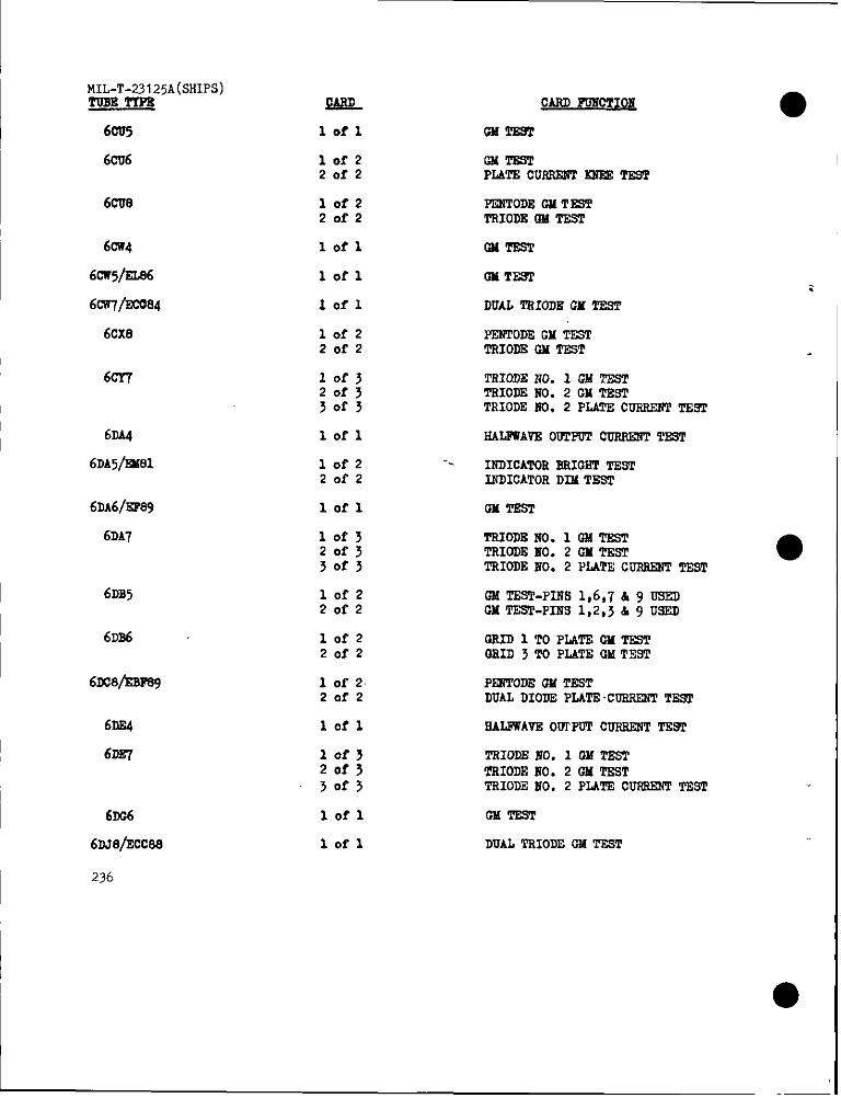
MIL-T-23 I 25A(SHIP5)TUBB27PS Q&L CARDF02iCTI02i
6CU5 lofl OX TSBT
102’220f2
GM mmPLATECURRENTIofEsTwr
6CU8 10f2 PENTODEW TSST20f2 TRIODR13MTEST
~
6ix4 lotl CMTEST
6c@2a6 lofl m TESTI 6ca7/sco04 Iofl DUALTRIODE(2HTE6T
6CX8 lofz20f2
PEI$PODEGM TEsTTRIODJICMTEST
60Y7 10f3Zofj50f3
TFUODE NO. 1 GM TESTTRIODENO. 2 GM TEsTTRIODEKO. 2 PLATECURRENTTEST
6DA4
6DA5@31
lofl SALPWAVEOUTPOTCWWS2!TTEST
lofz -.Zofz
INDICATORBRIGBTTESTINDICATORDIM TEST
6DA6/EP89
6DA7
lofl W T2ST
10f32of33of3
TRIOD8NO. 1 UM TSRTTRIODEuO. 2 GM TEST ●TRIODEHO. 2 llATE CURRENTTEST
6DB5 lofz20f2
CMTEST-PINS 1,6,7 & 9 USEDGMTEST-PINS 1,2,5 & 9 USED
6D56
61C@mF89
lofz2of2
QRIDITO PLATECM TEZ+TGRID 3 TO PL4TEGM T?X3T
1 of 220f2
P2NTODEUMTESTDUALDIODDPLATECURRENTTESI
6DE4 lofl SALFWAVEOUTPUTCURREIJTTE9T
I 6DE7 lof3 TRIODE EO. 1 OX TEST20f3 TRIODE170.2 W TEST!J0f3 TRIODE2f0. 2 PLATSCURRRiTTEST
lofl OMTssT
lofl DUALTRIODDGM TESTI 6r06
6DJ8/2cc8e
I 236
I
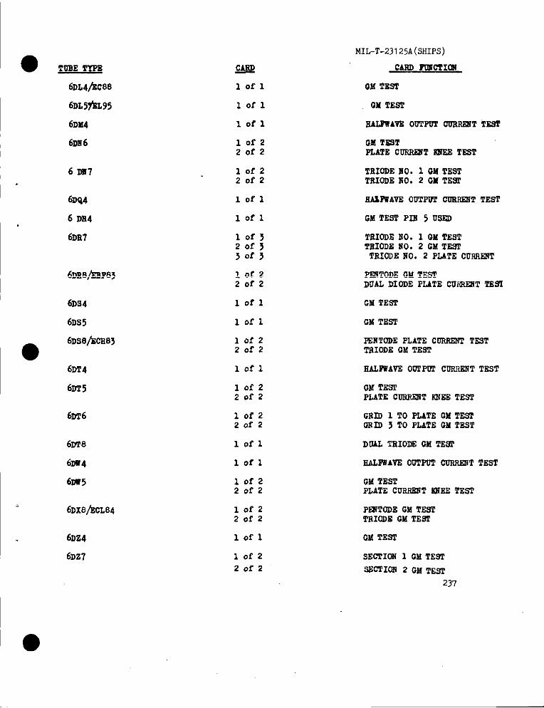
MIL-~-23 I 25A(SHIPS)
CARDF’CWOTI@lW?Plofl
Iofl
6DL4bC88
6DL5?’JCL95
6DX4
6DE6
UM TH’T
OH TES1’
lofl sALPWAV2OUTPOT00R~T T2sT
lofzZofz
GM TESTPLATECONRRITW TEST
6 DS7 10f220f2
‘2RIODEHO. 1 OMTES’ITRI03EMO. 2 GM TESf
6DQ4
6 Da4
6DE7
lofl NAL3%’AVEOUTPUICUSFUZ9TTEST
lofl GM TEsT PIN 5 USZD
lof>zof~3or3
TEIODECiO. 1 QM TESTTEIODENO. 2 CM TESTTRIODENO. 2 PLATE CURSIOW
lofzZofz
PZSTODEGMTESTDUALDIODE PLATE CUfREIiTTZS2
6D54
6DS5
lofl GM TEST
lofl CM TEST
●6DS8/kCE83 10f2
ZofzE%IITODEPLATE COSSENTTz9TTRIODEOM TEST
6DT4
6DT5
lofl SAL~AVZ 00TPW1’CUNR2RTTEST
10f220f2
GM TESTPLATE C-T NM2ZTEsT
6DT6 10f220f2
GEID 1 TO HATE GM TE=GRID 3 TO PLATE CMTEST
lofl6DT8
6DR4
6US5
DUAL TRIOIISGM TEST
lofl ZALFWAVZ OUTPUT CORRE2JTTEST
GM TESTPLATE CUSNESTS32S TEST
lofz20f2
6DX8/ZCL84 lofz20f2
PRiTODEGM TEsTTRIODECM TEST
6DZ4
6DZ7
lofl GM TEST
lofz
ZofzsECTION1 GM TEST
SWTION 2 GM TEST
237
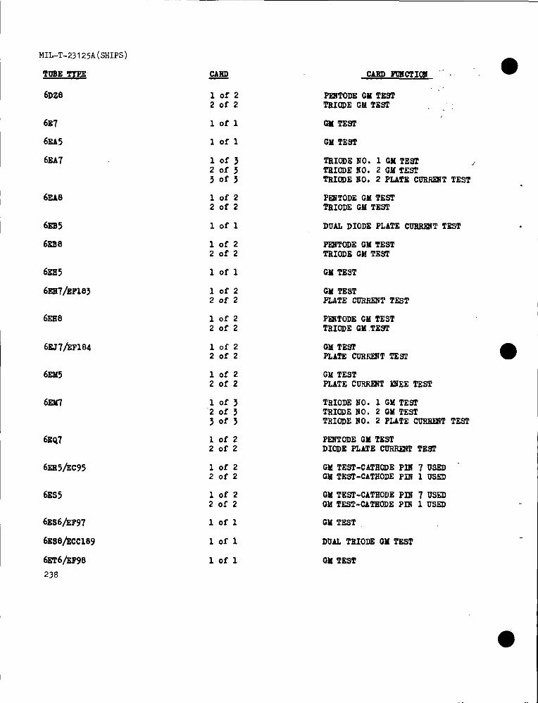
MIL-T-23125A(SHIPS)
~TOSE TfPZ
I 6DZ8
687
I 6EA5
I 6EA7
6EA8
I 6ES5
62s8
6ES5
6Es7/EFvs3
6ss8
I 6EJ7/kF184
I 6EM5
I 6En7
I6BQ7
I 6s2s5hc95
I 6ES5
6ES6jXP97
6JLSfJ/ECC189
6Er6/kF98
238
ML??
10f2Zofz
lofl
lofl
10f3Zofj30f3
lofz20f2
lofl
10f220f2
lofl
lofz2of2
lofz20f2
lofzZofz
lofzZofz
10f3“2of 330f3
lofz20f2
10f220f2
lofzZofz
lofl
lofl
lofl
OAF@ PGIICTI~ “’
P~TODE GM TESTTEIODEGM TESf
GM TEsT
GM TEW
TSIOOEHO. 1 cx TEST )TSIODE!S0. 2 GM TESTTRIODE110.2 PLATE CUSPRJTTEST
PRSTODEGMTESTTRIODE GMTEW
DUAL DIODEPLATE CUESHT TSST
Pi2fTODEGMTESTTSIIODEGMTEST
GMTEST
GMTESTPLATE COSSENTTEST
F’~TODE GMTESTTRIODECM.TEST
CMTESTPLATE COSSINTTESI
GM TESTPLATE cussmT 52JEETEST
TRIODENO. 1 GM TESTTSIODENO. 2 GM TESTTRIODENO. 2 PLATECURSSSTTEST
PE2iTODEGM TEsTDIODEPLATE CUST@?TTEsT
GMTEST-CATE@E Pll!7 USSIICM TE~-CATNODE PIif1 US2D
GM TEST-OATSODEP21i7 USSDGM TzsT-CATSODEPm 1 USED
GM TEST
DUAL TRIOLE3GM TEsT
W TEST
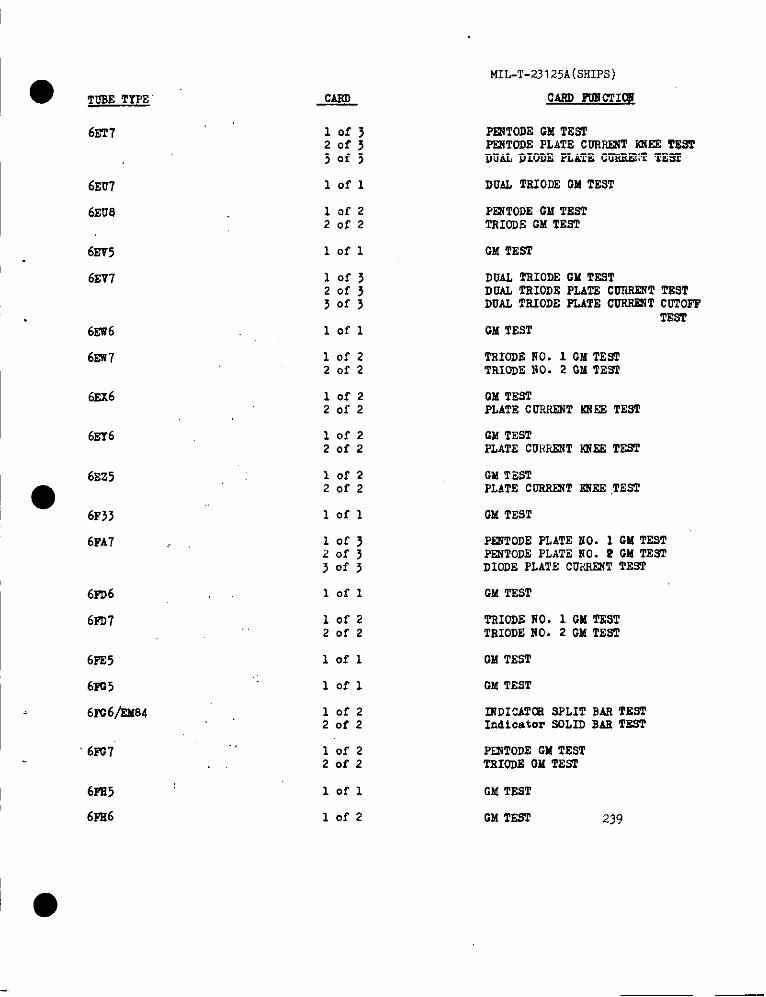
MIL-T-23 125A(SHIPS)
● TUBE TYPE CARD RJECTIf2i
‘,
lof}20f33of3
lofl
6E’N P~TODE GM TESTF%NTODEPLATE CDRIUXTiCiEETESTDUAL DIODE PLATE CCREEX’T‘IEs?!
6EU7
6EU8
DUAL l’RIOCEOM TEST
lof220!’2
PENTODEGM TESTTRIODECM ‘fEsT
61375
6EV7
lofl OM TEST
10f320f3Sof>
DUAL TRIODEGM TESTDUAL TRIODEPLATECURRENTTESTDUAL TRIODEPLATECURR2XTCGTOI’P
TESTGM TEST6EW6
6w7
lofl
1OI-220f2
TRIODENO. 1 GM TEsITRIODENO. 2 W TEST
QM TESTPLATECCRHSNT~ES TESl
6EX6 10f220f2
6EY6 10f220f2
GM TESTPLATE CURPXNTsNE3TEST
6EZ5
●6F33
10f220f2
GM TESTPLATE CCRRENTEKES.TEST
lofl GM TEST
6FA7 10f320f3
PEWTODEPLATEMO. 1 GM TESTPFNTODEPLATZNO. P GM TESTDIODE PLATE CCKRENTTEST30fj
lofl
lofz20f2
GM TEST6PD6
6m7 TRIODE170.1 GM TESTTRIODENO. 2 GM TEST
6PE5
6PG5
6PC6/Ef684
lofl GM TEST
OM TEST10:1
10f2,. 20f2
.,10f220f2
~DICAT~ SPLIT BAR TESTIndicator SOLLDRAE TEST
6i+v7 PENTODEGM TESTTRIOD2iOMTEST
6FI15
6pE6
lofl OMTEST
10f2 OtATEST 239
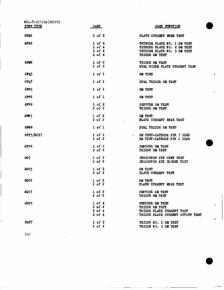
MIL-T-23125A(SHIPS)I .TDSETTPE
6FE6
6PSL7
I62?48
62w5
6FQ7
62%5
6F-?6
6P?8
6m 5
61W8
6P’r5/EC97
6PY8
6C5
6GC5
6CC6
6CD7
60E8
64F7
2L0
Zofz
10f420f43or44of4
lofzZofz
lofl
Iofl
lofl
lofl
lofzZofz
lofz20f2
lofl
lofz20f2
lofzZofz
10f220f2
lof220f2
lofzZofz
lofz20s2
10f42of430f440f4
lofzZofz
CARDPoxmm?
PLATECORilRiTF3!SST.RSP
TETRODEPLATEUO. 1 GM TESITETRODEPLATE HO. 2 CMTESTTETRODEPLATENO. 3 GM TESTTRIODE13MTEST
TRIODEGMTESTDUALDIODE PLATE C-T TESl
GM !l’EST
DUAL TRIODEGM TE5T
GMTE9T
P2WTODEGM TESTTRIODEGM TEST
GM TESTSLATE CORRRJTIMEETEST
DUAL TRIODE GM TEST
, CMTEST-CAT210DEPLN 7 US~GMTEST-CATEODEP2N 1 USED
PSWCODEGM TES2TRIODEGM TEST
RIDICATOREYE OPEN TESI’2RDICATOREYE U,QS~ TEST
GM TESTPLATECURRSGTTEST
CM TESTPLATECURRRITiGi2ETEST
P~TODE GM TE91’TRIODEGM TEST
●
PR?TODEGM TE91TRIODEGM TESTTRIODEPLATE CURRENTTNSTTRIODEPLATE CORRk2iTCUTOFPTEST
TRIODENO. I GM TESTTRIOIJENO, 2 CM TEST
●
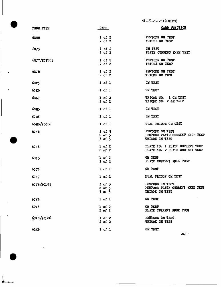
● TUBE TYPE
MIL-T-23 1254(SHIPS)
pAr!ll 3uECTIOI!
PRiTODECMTEsTTRIODECMT~T
6Gt18 10f22of2
6035 lofz20f2
CM TESTPLATECURRESTsWEETEsT
6CJ7/ECP801 lofzZofz
PE2TTODEGM TEsTTRIODEGM ZES’I
6GJ8 10f220f2
PEGTODEGMTESTTRIODE GMTEsT
6UK5
6GK6
6GL7
lofl GMTEST
lofl CMTEST
TRIODEliO. 1 GMTESTTRIODENO. 2 CMTESC
10f220f2
60M5
6CM6
6cx8/Ecc86
6Gl?8
lofl GMTEST
lofl GMTEST
DUALTRIODE CMTESTlofl
lofj20f330f3
PENTODEOM TESTPRSTODEPLATE CURSRiT~EE TESTTRIODEHA TEST●
6GS8 10f220f2
PLATERO. 1 PLATECUSIUXTTESTPLATEfIOS2 PLATE COIUWNTTSST
lofz20f2
CM TESPPLATE CtOGWST12WETEST
6GT5
6GU5
6GU7
60v8~cL85
lofl CM TEST
DUAL TRIODECM TsSTlofl
PENTODECL!TSSTP~TODE PLATE CURREX’TFWE TS92TEIODEGM TEST
lofl CM TEST60W5
6GV6 lofzZofz
GMTESTPLATE COTWENTXNEETEs’2
PW20DB GM TEsTTRIODEGM TEST
.me/kcL86 10f220f2
6CX6 lofl OM TESTal
I.*4-.

MIL-T-23125A(SHIPS)TUSETYPE
,. ,.
6GY6
6oYe
6RA5/lsc900
>6m6\,
6HC8
@3
6Ec8/hcP86
CARD PUNCTICN
lofl GM TEST
lof> TRIOOEuO. 1 PLATE CORRE2iTTSST20f5 TRIODEEIO. 2 OMTESl>Ofj TRIODEfiO. 3 GM TEST
lofl GM TEST
10f2 OM TESTZofz PLATE COERENTNNEETSST
10f J20f J3of3
PF2VfODEW TESTP12iTODEPLATE CORR121T~EE TEN2TRIOOECM TES2
lof220f2
PF2iTODEOMTEsTTRIODECMTEST
10f220f2
PRiTODEOX TESTTNIODEOM TEST
6NJ8 10f220f2
PENTODEW TENTDIODE PLATECDHRSNTTENT
6RL8 1OI-220[2
P~TODE GM TEsTTRIODEGM TE6T
6SM6 lofl Oh!TEST
6qs6 Iofl
., lofl
OM TE92
6ss6 GM TEST
6ss8 10f220f2
FIJTENO. 1 OM TESTPLATENO. 2 OM TEST
6RT6 lofl OM TEST
6ED6/hls7
6NI@ZLLS0 .,.
6EW8
!,,,
6EZ6 ,,,
6HZ8 .,,
w.
10f2Zofz
~DICATOS SPLITBAs TESTIGDICATOESOL2JIBAN TEST
lofz20f2
PENTODENO. 1 OM TENIPR7TODENO. 2 W TEST
..,’1 10f320f JJ0f3
lo.fl
10f3
CM ‘mm
PE2JTODEGilTEsT
~ToDE -E CURRENTKNEETEST
●

MIL-T-23125A(SHIPSJCARD FGSCTIOH
>Ory
lof2201-2
TEIODEGM TESI6EZ8
I 6JAa TETRCDEGM TEsTTRIODEGM TES2
GM TESTPLATECW.SRR?TIOTEETEST
6JB6 10!-220?2
6JR8
1- 6JC8
1OI-220f2
PE3fTODECMTESTTRIODEGM TWf
lofz20f2
PENTOUEGM T2STTEIODEGM TEST
lofl
10f220f2
GM TEST6JD6
6JE8 PENTODEW TESTTRIODECM TEST
I 6JF8 10f320f3>of~
PEXTODE CM TESTP12iTODEPLATECUPOIE:T tCWRTESTDIODE EAUWAVE OUTPUTCUIIUXTTERI
GM TER1’6.w6 lofl
IoC32of5jofj
PEI?PODEGM TEST
PLATE CGRR~T CO’KJPFT~~[pl.te 21PLATE CUR!WRTCDTOF’PTEST Plate1I 6JE8
a0f220f2
TRIODENO. 1 CM TESTTRIODENO. 2 CM TEs’I
PENTODEGM TESTTRIoDECM TEST
6JTe lofz20f2
I 6JU8 10f2 DUAL DIODE PLATECDRRENTTESP(DIOOES1 ma 3)
20f2 DUiL DIODE PLATE-CORHENTTEST(DIODES2 and 4)
6JV’9
6JX13/ECE84
6KA8
10f220f2
Pk2JTODECM TEsPTEIODEGM TE=
10f220f2
PENTODEPLATECURRENTTESTTRIOiJEGM TFSTI
10f22cf2
PRITODECM TESTTRIODEGM TEST
Z3
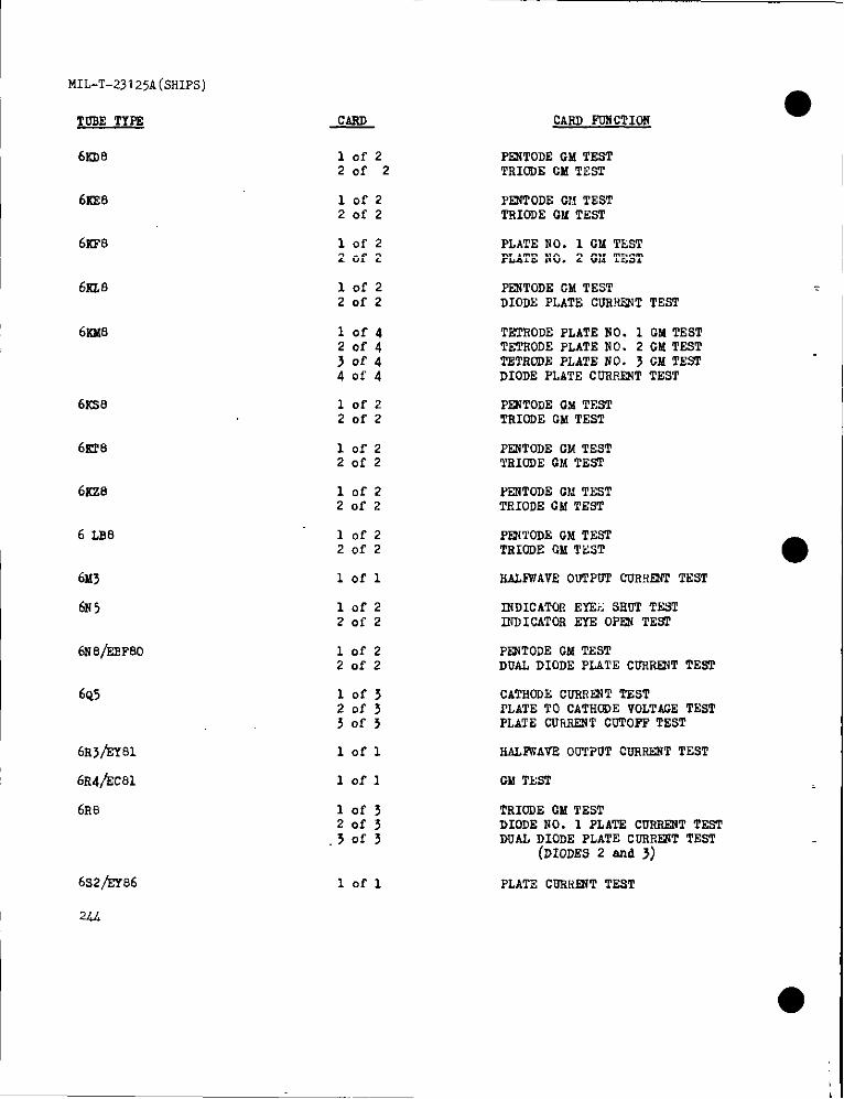
MIL-T-23I25A(5HIPS)
TORETYPE
6KD8
6KE.9
6KP8
6s7,8
CARD PDNCTION
10!-220f2
PENTODECMTESTTRIODECM TEST
1OI-220f2
IWTODE Cl!TESTTRIODEQM TEST
1OI-220f2
PLATENO. 1 CM TESTPLATENO. 2 W TEST
lofz20f2
FXNTODEGMTESTDIODEPLATE CDR~T TEST
61LM.9 10f4Zof ’1J0f44oi’4
TETRODEPLATENO. 1 GM TESTTETRODEPLATENO. 2 CM TESTTETRODEPLATE NO. 3 CM TESTDIODE PLATE CDRRQ4TTEST
6SS8
6FJ18
6s28
6 LB8
6x>
6N5
6Na/ERP80
6Q5
6FW%Y81
lofz20f2
PE2iTODEGM TESTTRIODECM TEST
10f220f2
PF,WTODECM TESTl’RICDECM TEST
lofz20f2
H7NTODEGM TESTTHODE CM TEsT
10f220f2
PBXTODEGM TESITRIODEGM TEST
lofl RAL~AVE OUTPOT CUR!U2ffTHT
10f220f2
IJDICATOi+EYEE SHOT TESTINDICATOREYE 0PF2JTEST
10f220f2
PFXTODEGM TESTDUAL DIODE PLATE CURRENTTEsT
lof32of3~ofs
CATMODECNRN~T TESTPLATE TO CATHODEVOLTACETESTPLATE CDm12iTCDTOPPTEST
HALFWAVS00TPUT CNRRENTTEST
GMTMT
lofl
lofl
6R8
6s2/EY86
2u
lof~Zofj.30f3
TRIODECM TESTDIODENO. 1 pLA~ CURRSNTTESTDUAL DIODE PLATE CORRSNTTEST
(DIODES2 md 3)
lofl PLATECDRWiT TEST
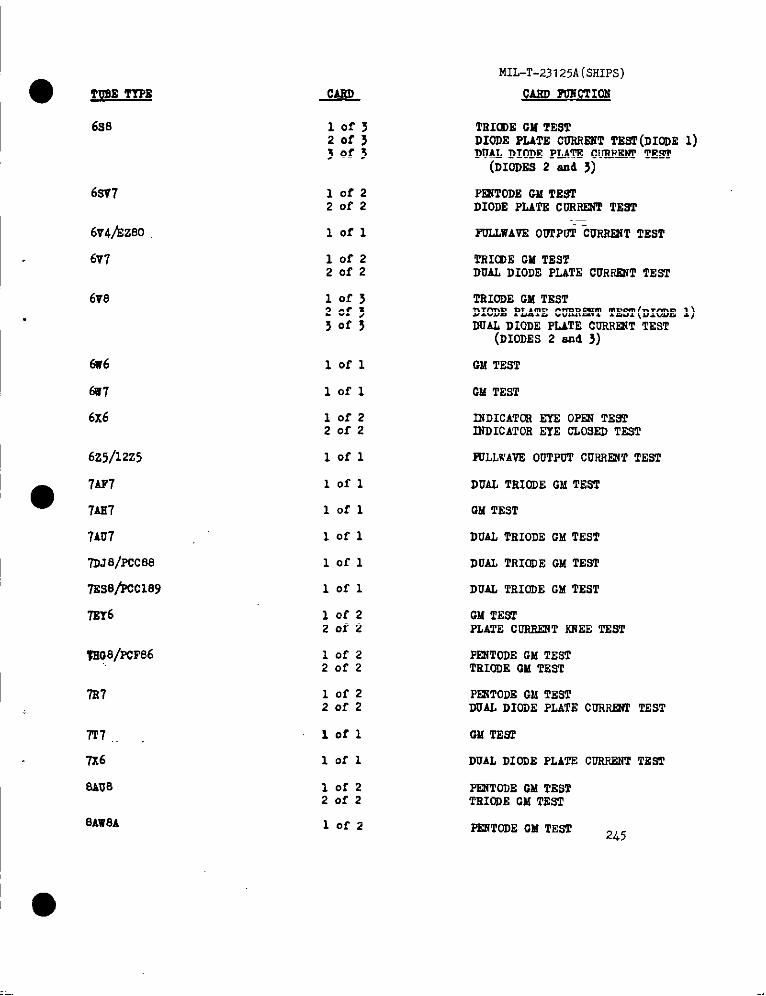
● ym TTPL’
6s8
6SV7
6v4/zz80
6v7
6V8
6H6
6W7
6x6
6z5/12z5
●7AP7
lA2fl
7LU7
7DJ8/Pcc88
7Es8/R2c189
7E16
w38/PcF86
7R7
m ,
7x6
sAlJ8
8Aw8A
~
10f320f3>ofj
10f220f2
lofl
10f220f2
10f320f330f3
lofl
J.ofl
10f220f2
lofl
lofl
lofl
lofl
lofl
lofl
10f220f2
lofz2of2
lofz20f2
lofl
lofl
10f220f2
lofz
MIL-T-23125A(5HIPS)
CARD FUWCTIOS
TRICDECM TESTDIODE PLATE CURRESTT22~(DIODE1)DUAL DIODE PLATE CUEPJW1’TEsT
(D10D252 and 3)
PR2TODECM TESTDIODE PLATE CORRRiTTEST
FQLLWAVEOUfPti:U5R22iTTEST
TRICIDEOM TES?DUAL DIODE PLATE CURRWI TEsT
TRIODEGM TESTDIODE PLATE CURRHT TEST(DIODE1)DUAL DIODE PLATE CORRR?TTEST
(DIODES2 md 3)
CM TEST
OM TEsT
f32DICATCREYE OPEW TE9TISDICATOREYE CLOSEDTEST
KILLwA.VEOUTPUTCURRENTTEST
DUAL TRIODEGM TEST
GM TEST
DUAL TRIODEOM TEST
DUAL TRIODEGM TEsT
DUAL TRIODEGM TEST
GM TESTPLATECURRENTkTCdSTEST
PEIITODEGM TESTTEIODECM TES7
PEliTODEGM TESTDUAL DIODE PLATE CDRREZT2TEST
DUAL DIODE PLATE CUEREWTTZWI
PR7TODEGM TESTTRIfd)EGM TEST
PESTODECM TEST 245
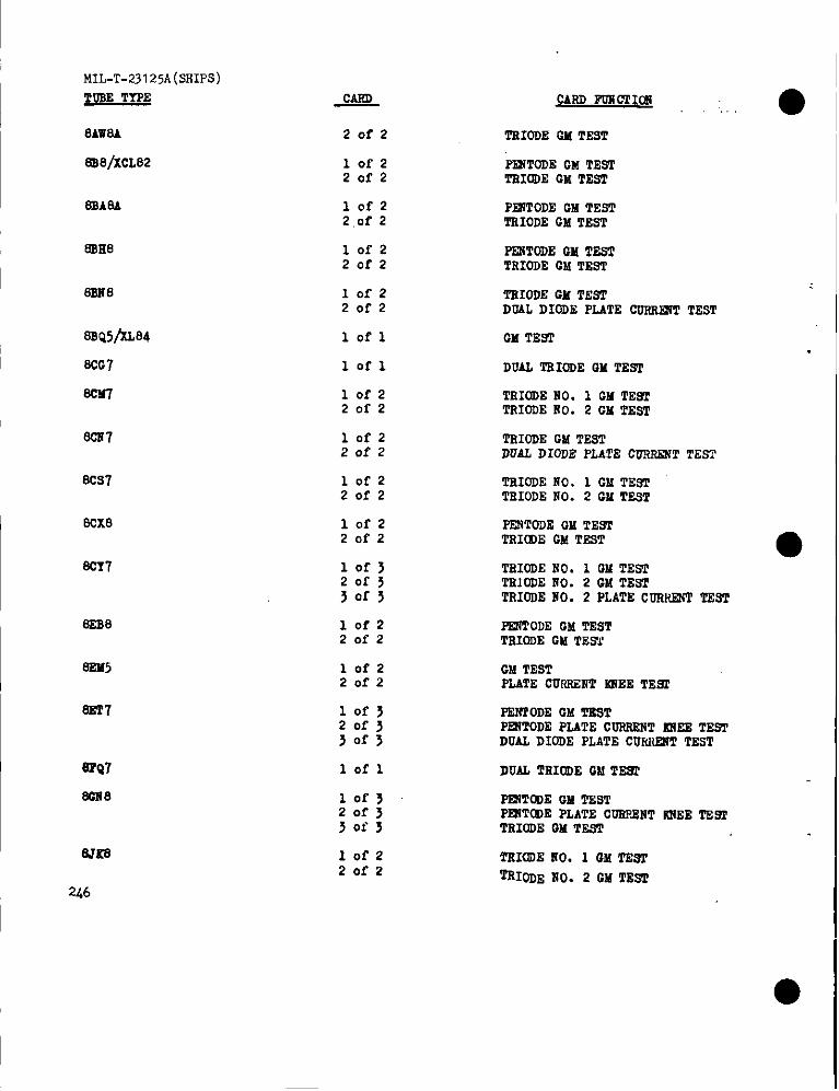
MIL-T-23I25A(SHIPS)
~uSE TYPE
8AWA
El18/XCL82
SBASA
SSR8
EES8
SSQ5/kL84
8CG7
SCM-l
SCS7
8CS7
SCX8
scr7
SSS8
EE2i5
SsTl
SPQ7
SGn8
am
246
20f2
10f220f2
10f22.of 2
10f220f2
10f220f2
lofl
lofl
lofz20f2
10f220f2
10f220f2
10f220f2
lofj20f530f3
10f2Zofz
10f2Zofz
lof>20f330f3
lofl
10f J20f33of3
lot-zZofz
CARD POSCTIm,. ●
TSIODEGM TEST
“%iTODEGM TESTTSICOECIATEST
P~ODE W TESTTRIODEGM TEST
PENTODEGM TESTTRIODE CM TEST
TSIODEGM TE$TDoAL DIODE PLATE CDRRRJTTEST
GM TEsT
DUAL TEIoDEGM TEW
TRIODEHO. 1 GM TESTTRIODERO. 2 CM TEST
TRIODEGM TESTDUAL DIODE PLATE CNHSENT TEST
TsIODENO. 1 GM TESTTSIODENO. 2 W TEST
PENTDDEw TR91TRICS)EGM TEST ●—TSIODENO. 1 GM TESTTRIODENO. 2 GM TEsTTRIODENO. 2 PLATECURP.RWTEST
-ODE GM TESTTRIODEGM TESY
GM TESTPLATECURRENT~EE TE9f
PSNTODEOM TESTPRITODEPLATECDIMINNT2DiEETESTDUAL DIODE PLATECUMWT TEST
DUAL TRIoDEGM TES2
=CDE CM TESTPESTODEPLATECGRPJWTIUIEETESlTRIODEGM TEST
TRIODEKO. 1 GM TE211
‘fRIODExo. 2 GM TESI
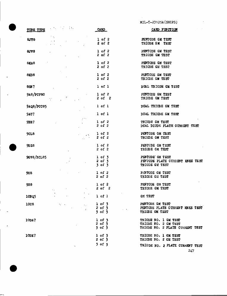
● TUBE TIPE ‘“” ‘“MIL-T-23I25A(SHIPS)
CARDPONCTI~
FENTODEGM TESTTRIODECM TEW
PENTODEGM TEsTTRIODECM TEST
PENTODECM TESTTRIODEG?.!TEST
PSNTODEQM TESfTRICDEGM TEST
DUAL TRIODE GM TEST
PENTODEGM TESTTRIODEGM TEST
DUALTRIODEGM TE9T
DUAL TRIODEGM TE9f
CARD
SJT8 ,;,,.
8JV8
lofz201-2
lofzZofz
8KA8 lofz20f2
82s8 lofzZofz
8=7
9A8~CFS0
102-1
lofzZofz
iAiQ8/p0205 lofl
9AU7 lofl
9SR7 10f2Zofz
TRIODEGM TE=DUALDIODE FLATECORRRJTTE92’
9CL8 .,, lofzZofz
PFETODEGM TESTTRIODEGM TEST
PENTCDEGM TE9fTRIODEGM TEsT
FZSTODE’OMTESTPENTODEPLATE CUF.RmTioim TESTTRIOI)E GMTEST
PsNTODECMTESTTRIODECl! TEST
lofz20f2
9GV8/XCL85
lofz20f2
9U8
9X8 lofzZof 2
PENTODEGM TESTTEIODEGM TEST
10SQ5 lofl CM TEST
10c8 ‘, lof32of330f3
PESTODEGM TESTP32V20DEPLATECU3N?ENTWSE TESTTRICDEOM TEST
TRIODENO. 1 GM TE91TRIODEHO. 2 GM TESTTRIOIIENO. 2 PLATECUIWESTTESI’
10DA7 10f320f330f3
10DE7 10f320f3
TRIODENO. 1 GM TEs2TRIODENO. 2 GM TEST
30fj TRIODENO. z PLATECUslimiTTSS’2
2.47
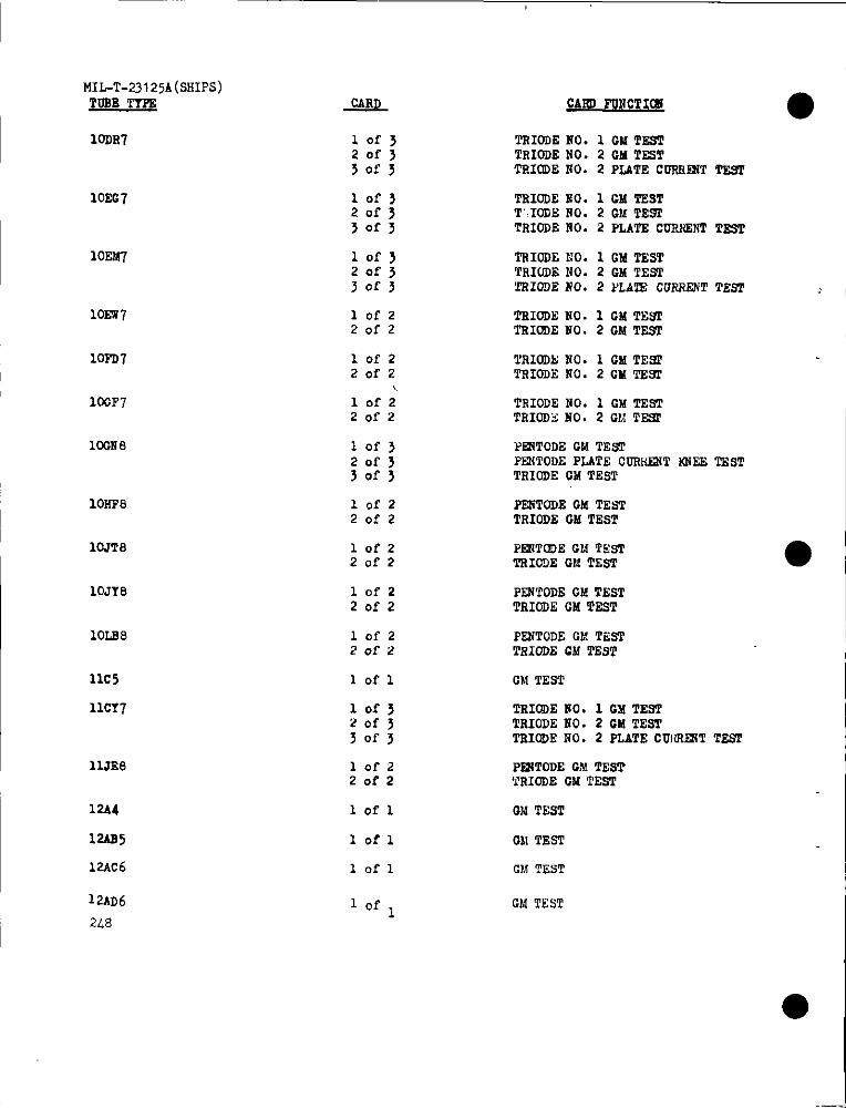
m-T.231 25A(SHIPS)TOSE TYPE
10DR?
10EC7
10EW
10ES7
10PD7
IOOF7
10GI?8
10W8
10JT8
10JY8
10LS8
11C5
llcr7
11JE8
12A4
12AS5
12Ac6
12AD6
2/+8
JANL
lofjZof>Tofy
10f3201-5>Ofy
10f32of3~of~
lofzZofz
10f220f2
lofz20f2
10f3Zofy30f3
10f2Zofz
10f220f2
10?2Zofz
10f220f2
102-1
lofj?Ofy3of3
10f2Zofz
lofl
lofl
lofl
mm PQNCTW ●TNIODENO. 1 GM TEST‘PRIODENO. 2 CM TESTTSIODENO. 2 PLATE COFRIXTTEST
TRIOOEMO. 1 GMT2STT“.I03E NO. 2 GMl!ESi’TRIODEiiO. 2 PLATECURNENTTEST
‘ITcIODENO. 1 GM TESTTR1ODE1{0. 2 GM TEST‘TRIODENO. 2 PLA7S CURRENTTEET
TRIODENO. 1 GM TESTTSIODENO. 2 GM TEST
TRIODENO. 1 GM TEWTRIODENO. 2 CM TNST
TRIODENO. 1 GM T2?7TTRIODSNO, 2 GM T=
PENTODEGM TEsIPECiTODEPLATE CON!!T IOWETESTTRIODEGM TEST
PENTODEGM TEsITRIODEGM TEsT
PENTOOECl{TESTTRICDEGldTEsT
PENTODEGM TESTTRIODEGM TEST
P2NTODEGM TESTTRICDECM TEsT
GM TEST
TRICDEEO. 1 CM TESTTRIODENO. 2 CM TESPTNICDENO. 2 PLATECOrfRIXTTESI
p~TODE cM TESTTN1ODEGM TEST
GldTEST
GN TEST
GM TEST
CM TEST
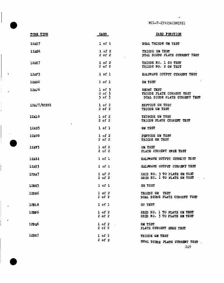
MIhT-231 25A (SHIPS)
ToM TYPE CARDPORCTI~
12AD7
12AE6
10 I-1 DOAL TRIODEOM TEST
10f220f2
TRIOIWGM TESTDUAL DIODE PLATE CGRFL!NTTSST
12AE7 10f220f2
TRIODENO. 1 GM TESTTRIODENO. 2 GM TEST
12AH
12AG6
12AJ6
lofl SALP#AVEODTPDTCURRF2JTTEST
lofl GM TEST
SHORTTSSTTRIODEPLATE CORRSNTTESTDUAL DIODE PLATE CUSF.FIITTBBT
12AJ7/NCE81 REPPODECM TESTTRIODEGM TEST
10f220f2
12AL8 10f220f2
TETRODEGM TESTTSIODEPLATE CUNRF2?PTESf
12AS5 1OI-1 CM TESI
12AU8 10f220f2
2TMTODEGM TEsTTRIODEGM TEST
●12AV5 lofz
20f2GM TESTPLATE CIJR1,ZNTIOIEETBST
12AX4
12AY3
12BA7
lofl NAIJWAVEODTPUTCURRSNITES1’
SALPUA?EOUTPGTCLOU%RPTE92Iofl
1of22of2
GRID NO. 3 TO PLATE 12MTE~GRID2i0.1 TO PLATEGM TEST
12BK5
U?BK6
lofl GM TEST
lofz20f2
TRIC4)EGM TESTDGALDIODEPLATECURIW3TTE9f
12SL6
12sN6
lofl
10f220f2
GSID NO. 1 TO PLATE GM TESTCR~ HO. 3TO PLATE GM TEW
10f220f2
CM TESTPLATECGTMNT SSEETESI
123B7 1 of 220f2
TRIODEGM TEST
DUAL DIODE PLATE CORREMTl’EsT
249
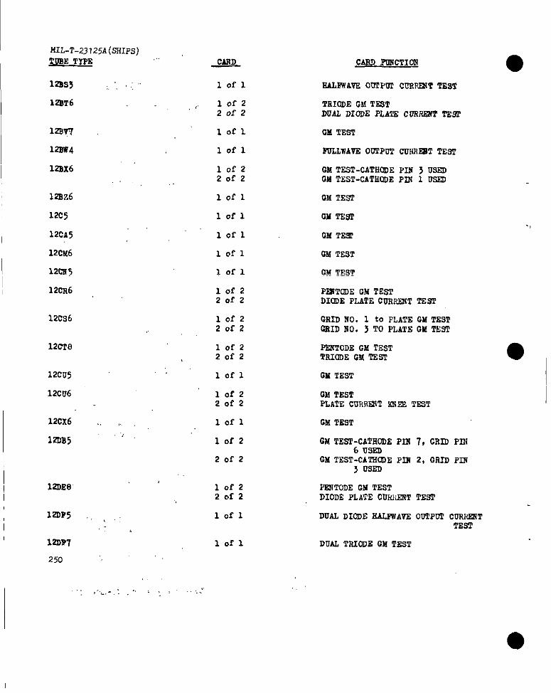
MIL-T-23 125A(sHIPs)TUSE TYPE
122.s3
12sT6
12BV7
12SW4
122x6
lofl EAIJWAVEO~P!llc~~T TEsT
lofzZofz
TRIODEHI TRSTDUAL DIODE PLA’ZE CDRSEST TE9
GM TESTlofl
lofl ~LWAVE OUTPUTcunRmTTES’2
lofz20f2
CM TEST-CATHODEPIM 3 USSllOM TEST-CATHQGEPLN 1 _
12sz6
12c3
I12cA5
1 OX-1 GM TEST
lofl
lofl
12cM6
12CW5
12CR6
12cs6
12CT8
12cu5
12cw6
lofl fJFdTEST
lofl
lofz20f2
CMTEST
PEXTODEGM TESTDIODEPLATECOffF~TTEEfl
lofzZofz
GRIDno. 1 to PLATEOM TEST~ID no. 3 TO pLATE GMmm
lofzZofz
PEI?TODEGM TESTTRIODEm.fTEST ●
Ilofl
lofzZ.afz
GM TEST
GM TESTPLATE CUR@lT ~E3 TEST
12CX6 ,, ,,
laB5.,
12DE8’
12GF5 ., , ,
I ,-,12D?7
25o
I “’’’””’
,.,
lofl GM TEST
1OI-2
Zofz
GM TEST-CATEODEPIS 7, CRLO PIN6 USEO
GM TNST-CA~~E pm 2, 17RD Pm3 USED
lofz20f2
lofl
PEWTODEGM TESTDIDDE PLATE CUiOIEWTTEST
DUW DIODESfALPWAVS00TPGTCUSWRTTEST
lofl Du~ TRIODEGM TEST
..,,,
I
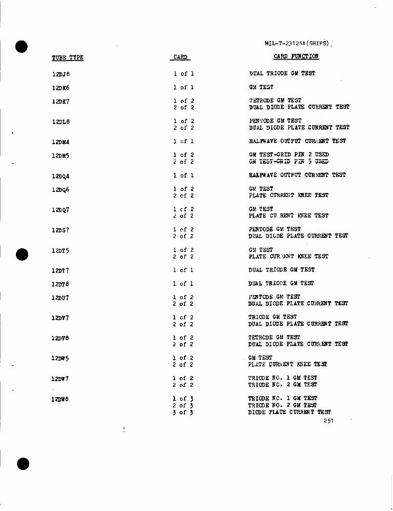
MIL-T-23125A(SHIPS)
CARD POWCTIOfiTUSE TYPE
12DJ8
12DK6
12DK7
lofl
lofl
DUALTRIODECMTEST
C!i TEST
ThTEoDECMTESTDUALDIODEPLATE CURSE?(T7!EWT
10f22of2
1211L8 10f220f2
Pk21i’ODEGM TESTDUAL DIODE PLATECURRENTTEST
HALEwAVE002PUT CUMJWT TEST
GM TEST-GRIDPIN 2 USSDGM TEsT-GRIOPIR 5 USED
RALEWAVEODTPOTCUWENT TEST
GA!TESTPLATE CURRENTRNE2 TEST
12DM4
12DM5 lofz20f2
12DQ4
12DQ6
lofl
10f22@f2
12W47 lcf220f2
GM TESTPLATE CU..M2JTKW2ETEsT
12DS7 lof220f2
PENTODEC!!TESTDUAL DIGDE PLATECURRENTTESf
GilTESTPLATE CUR:~W!WTIUWETEST
DUAL TRIODEGM TEST
DOAL TRIODEG?ATEST
I’5XTODEGtJTESTDUAL DIODE PLATECUNRENTTEWf
TRIODEW TESTDUAL DIODE PLATECUR-T TEST
●12DT5 10f2
20f2
12DT7
12DT8
12DU7
lofl
lofl
10f2Zofz
12DV7 lcf22of2
12DV6 10f22of2
TETRODECM TEWTDUAL DI03E PLATSCDFfiEiTTERI
lofz20f2
GM TEsTPLATS CORhENTtOiEETE=
12DW5
12DW7 10f22of2
TRIODENO. 1 CM TESTTRIODEfiC.2 GM TE9T
12DW8 lofj20f3~or>
TRIODENC. 1 GM TEsTTRIODENO. 2 GM TESCDIODE PL4TECUP~lNT2’SS2
251
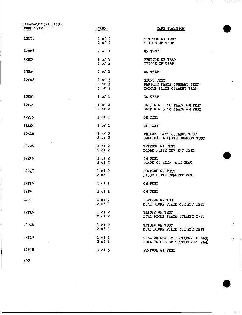
I MIL-T-23I25A(sHIPs)WISE Tms CARD iWUCTION
I 12DY8 lofz20f2
TETRODEGM TESTTRIODEGM TEST
CM TFX3T
P2MTODEGM TESTTHIODEGM TEST
GM TEST
siiol?TTEST
I 12Dz6
12DZ’9 lofz201-2
~
122A6
12EC8
lofl
lof>Zof}3of3
PSNXODEPLATE CORRRJT TESTTRIODEPLATECDRWT TEST
12ED5 lofl GM TEST
GRID f?O. 1 TO PLATECM TESfORIU NO. 3 TO PLATE GM ‘TEST
GM TESl
GM TEST
TRIODEPLATE CDSkiWTTESTDUAL DIODE pLATE CWRX~T TEST
TETRODEGilTESTDIODE PLATECDR1>UINTTESI’
GM TESTPLATECIY:REXT~EE TEST
12SG6
122Ei5
I 12EK6
12EL6
1ZSM6
12Eii6
lofzZofz
lofl
lofl
lofzZofz
lofz20f2
lofzZofz
12EQ7 lofzZofz
?12iTODEGM TEsTDIODSPLATE CGRELNTTEST
12Ez6
12F5
12F8
lofl GM TES7
GM TE91
PE2+TODEGA!TESTDUAL DIODE PLATECOMG:;TTEW
TRIODEGM TEsTDUAL DIODE PLATE CUHWNT TES2
lofl
1OI-2Zofz
I 12FK6 lofzZofz
I 12FM6 lofzZofz
TRI02EGklTEL31DUAL DIDDE PLATE CURERiTTEST
12FQ8 10f2Zofz
DUAL mODE CM TEST(pLATEsLA>DUAL TEIODEOh!TEST(PLATEs2&4)
PKUTODEGM Th’sP12FR8
252
lof>
●
___
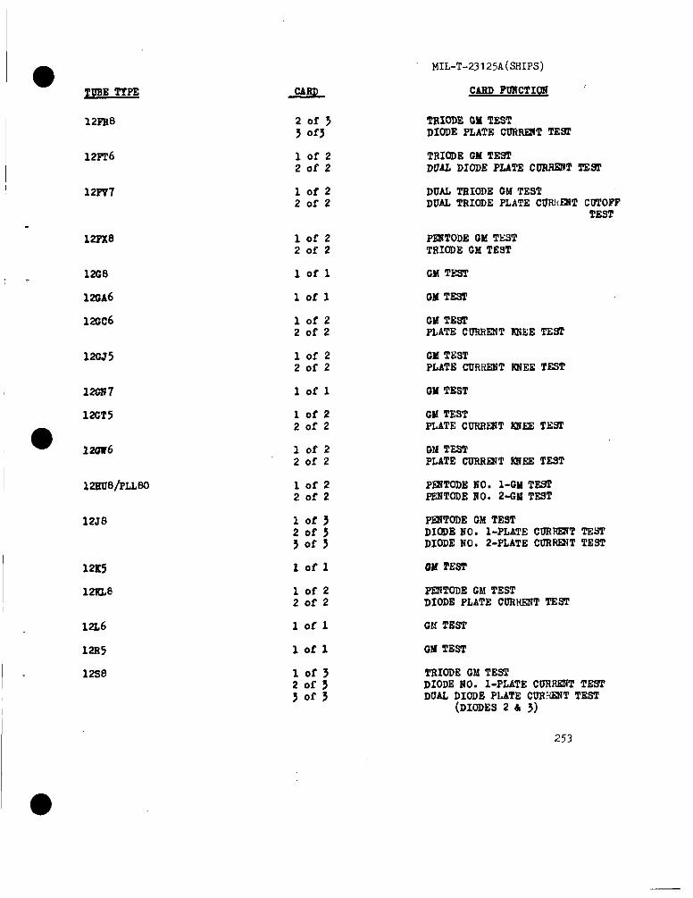
MIL-T-23125A(SHIPS)
●mm TfFE CARD FDNCTION
122%8 TRIODEGM TXYTDIODE PLATE CON~T TES2
12FT6 1OI-220f2
TRIODEOMTE.WDUAL DIODE PLATECONHSN’TTE=
12FP7 10f220r2
DUAL TEIODE CMTESTDUAL TRIODEFLATE CUNI<SNTCOTOPF
TEST
122’28 1OA-220f2
PISITODECL!TESTTRIODEGM TEST
GM TEsTlofl
lofl
12s8
r2DA6
120c6
QM TEST
10f220f2
GM TE22PLATE CURRENTK?EE TES2
10f220f2
GM TESTPLATEcDRHENTNliEETEST
120J5
121m7 1OL-1 GM TEST
CM TESTPLATE CURRENT2MEETEYT
12CT5 lofz20f2
lofz20f2
GM TESTPLATE CDSNE2TTNNEE TEST
12su8/PLLBc
12S8
10f220f2
PFXTODEHO. l-GMTNS1’PRNTODE2i0.2-W TN9T
PERTODE0!6TESTDIODENO. l-PLATECURRENTTN5TDIODENO. 2-PLATECOR~T TEsT
12S5
12NL8
OM PERT
10f220f2
PENTODEGM TESTDIODE PLATE CON!WT TEST
lofl GM TEST12L6
12s5
12s0
lofl GM TEST
10f320f5jofs
TRIODEGM TE.71DIODENO. l-PLATECURRENTTESTDUAL DIODE PLATE COE:?S2TTTEST
(DIODES24 3)
253

I
MIL-T-23125{(SHIPS)
~ . .
12u7
12v6
12u6
1224,
12Z3
13cM5/xL>6
13CN4
13DE7
13DR7
13EN7
13FD7
13PR7
14A4
14A5
14s8
14s7
14F8
14CT8
25L
~
lof~20f J30f~
lofl
lofl
lofl
lofl
lofz20f2
lofl
10f JZof>>Ofj
lofj20f JSofy
lofzZofz
10f JZofj3of3
lofzZofz
lofl
lofl
lofzZofz
10f220f2
lofl
Iofz20f2
GAND FTIu2T1CW ..,.
ZZORTSAND LSANACETESTTRIODERO. 1 PLATE CURRENTTEST”TRIODERO. 2 PLATE CUSRSNTTEST
GM TEST
OM TEST .,
FOLLWAVN00TPw2CUN~T TESI’
EALFWAVNOUTPUTOURRRTTTE~
W TESTPLATE CURRENTNEEETEST
GM TENI’
TRIoDEMO. 1 CM TZNCT210DENO. 2 CM TEsTTRIoDENO. 2 PLATE CURRSN?TTEST
TRIODEEO. 1 12MTENTTsIODENO. 2 CM TESTTRIODE110.2 PLATE CURRENTTEST
TNIODENO. 1 OX TNSTRIODENO. 2 CM TEN2TRIODEHO. ~ PLATECUFRSNTTEST
TRICDENO. 1 QM TESTT1710DENO. 2 CM TEST
TNIODENO. 1 CM TESTTEIODENO..2 CM TESTTRIODENO. 2 PLATE CU2REWTTEs2
TZIODENO. 1 GM TESTTRIODENO. 2 CM TEST
GM TEST
CM TZ9T
EEPTODEGM TESTDUALDIODE PLATECURRENTT=
FENTODEC!dTEsTDUAL DIODE PLATECUNF.EYTTESI
DUAL TRIODEGM TZST
TZIODEGM TESfDUAL DIODE PLATECCCi2@tTTEsT
●
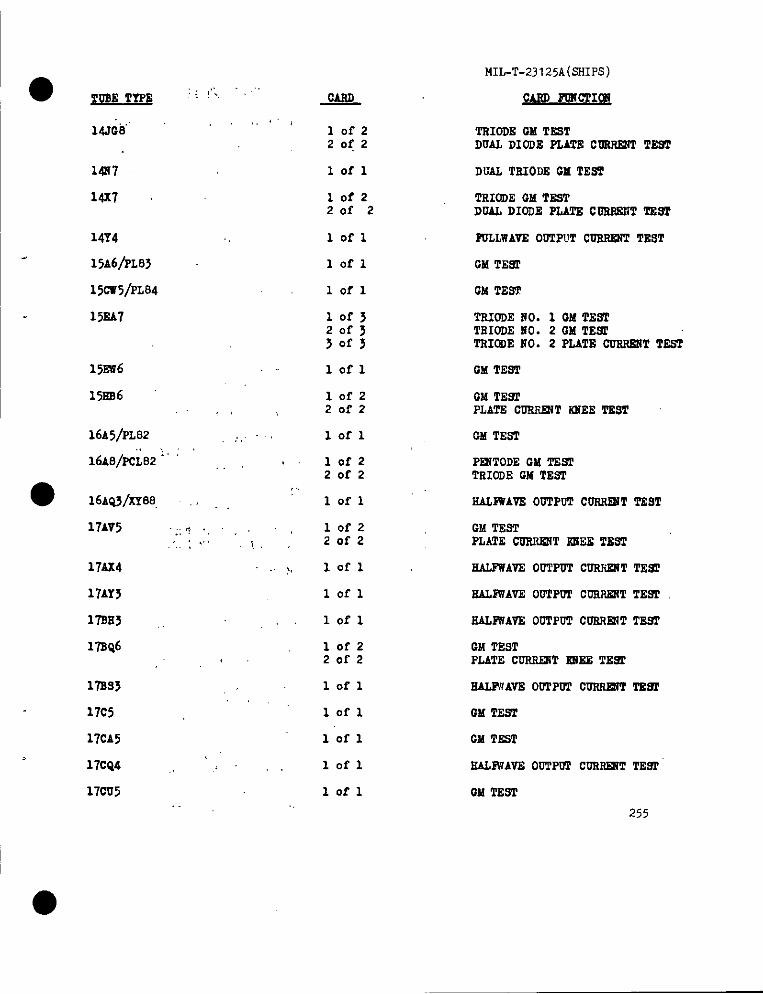
w E TWE; .: !,’,,
M.&l”
M57
14X7
14Y4
15A6/PL83
15cw5/PL84
15EA7
15Ef?6
15RB6,,
16A5/PL82 ,.,,
16A8/PcL82: ;
16AQ3/xY88, .,
17AV5 .;:? .,. . ... .i
17AX4
17AY3
17SE5 ,,
17SQ6‘.
17ss3
17C5
17CA5
17ce4 ‘ ,
17CD5
-&Q
lofzZofz
Iofl
10f2Zofz
loi-1
lofl
lofl
10f3Zofj~of~
lofl
10f220f2
lofl
10f2Zofz
,lofl
lofzZofz
lofl
lofl
lofl
10f2Zofz
lofl
lofl
lofl
lofl
Iofl
MIL-T-23125A(SHIPS)
w~~w I
TRIODEGM TESTDUAL DIODE PLATE CWIRIT TE9T
DUAL TSIODE GMTESI
TRIODEGMTE5TDUALDIODE PLATE C0256WTTHAT
2WLLWAVR001!PuT~ TEsT
CM TEST
TRIODE2?0.1 OM TEi?lTRIODENO. 2 GM TE~TRIODENO. 2 PLATE ~T TE5T
CM TEST
QM TE91PLATE C-T KJTEETSST
GM TEST
PRITODEGM TESTTRIODECM TEST
SAHWAVE 00TPuTC-T TEST
GM T&92PLATE COSilWJT2UiEETEST
RALPWAVE00’lPO’2CIFilWiTTE.W
RALIW’AVEOGTPWPCOliIWIT TEW
RALPWAVS00TPOT CWOIR?TTESI
GM TESTPLATECORRR3T2GJEETE9P
OM TES’I
GM TE5T
RALPUAWE00’f~ CDR~T TEW
QM TEST
255
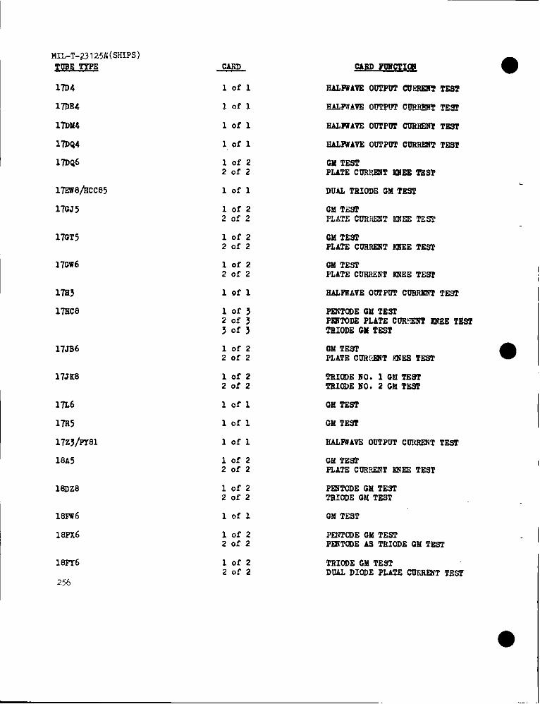
MIL-T-Z3I25A(SHIPS)
2~E -
17D4
17DE4
17DM4
17DQ4
170Q6
171vi?8ftlcc85
170.75
170T5
17Gw6
17s3
17SC8
17JB6
17JK8
17L6
17s5
17zj/FT81
18A5
1SDZ8
113FU6
18Px6
18Pr6
256
~
1OI-1
102-1
lofl
lot-l
10f220f2
lofl
Iofz20f2
lofzZofz
Iofz20f2
Iofl
lofjZofj30f>
lo f-zZofz
lofzZofz
Iofl
lofl
lofl
lofz20f2
lofzZofz
lofl
lofz20f2
10f2Zofz
SAIJWAVSODTPGTCVt21ElVTTZST
SALFWAVZ ODTPOTCDSS5TTE91
EALPWAVEODTPWfCDESSN’2TEST
EALFWAVE00TPUTCURSEXTTEST
GMTESTPLATECOTOIR?T~EE TEST
DUAL TSIODEGM TEW2
GMT.z.WPLATE COTIREI!TtOH2E‘2SS2
GM TEWPLATECOS~T WXEETSS2
GM TEsTP2,ATECOSSENTK2iEETES2
SAWVAVE 00T~ CDFOISNTTEWI
~TODE OM TESL’~TODS PLATECOR!TXTEJEETA@TSIODEGM TEST
W TESTPLATECDRF12iTiCWETEST
TSIODEHO. 1 GM TESTTEICI)EIiO. 2 GM TE9T
GM TEST
GMTESI
EACJNAVEODTPOTCORSSNTTEsT
GM TE9PPLAT2 COR?~T WEE TEST
PRITODE GM TESTTSIODEGM TIvET
GMTEST
PFLWTODEGM TESTPEIWODEAS TsIODEOM TEST
TRIODECM TESTDUAL DIODEPLATE CDIWICTTESP
●
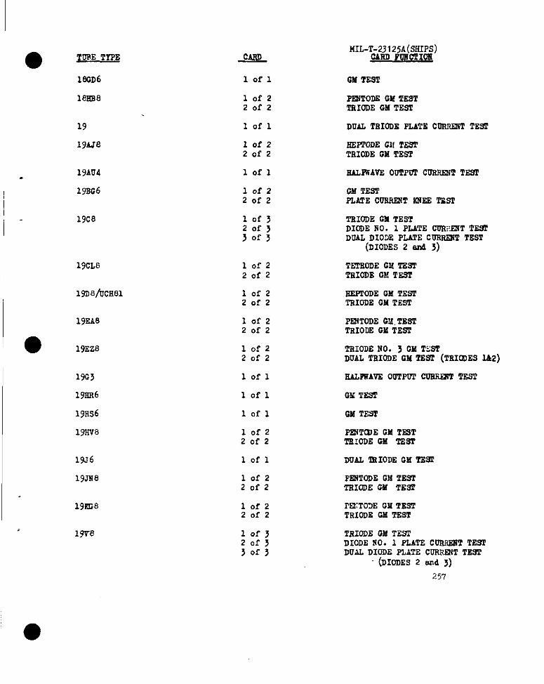
● TORE TYPEMIL-Tti2~l 255(~HIPS)
lscD6
18Rs8
Iofl GM TEST
lofzZorz
=ODS W TESTTRIODEGM TEsT
19
19AJ8
lofl DUAL TRIODE PLATE COmRiT TESI’
lofzZofz
SEFTODEGM 2’ESTTRIODEGM TEsT
19AU4
19EG6
lofl EAIJWAVZ00TPoTCORMMT TES1’
lofzZofz
GM TESTPLATE CUR~T INTEETSST
19c8 lofj2015jof>
TEIODEGM TESTDIODENO. 1 PLATE COl@NT lWS1’DOAL DIOIE PLATECORRE2?TTEST
(D10DE524 3)
,-
19CL8 lofzZofz
TE2SODEGM T&9PTEIODEC!!TEST
lma/lJcE81 lofzZofz
EEPPODEGM TESTTRIGDEGM T.ssT
19EA8
~o 19Eza
lofzZofz
PRITODSW, TESTTsIODEGM TES2
lofzZofz
TRIODENO. 3 GMTESTDUALIfRIODEGMmm (TRIfDE5Liz)
EALPwAVE00TPOTCDERINTTEST19G3
1921R6
1911s6
19RV8
lofl
lofl
lofl
G!ATEST
GM TEST
lofz20f2
P~T~E GM TEST‘LWODEGM TEST
19J6
19JN8
lofl
lofz20f2
DUAL IRIODEGM T2=
PE2TTODEGM TES7TRIODEGM TE92
19KG8 lofzZofz
i’EKT02EGMTESTTRIOMCGM TEST
19T8 lof~20f33of3
TRIODEGM T.HI’DIODENO. 1 PLATE CORRKSTTESTDUAL DIODE PLATE CORRRJTTEsT
(DIODES2 =d >)
257
‘a

MIL-T-23125A(sHIps),,
~ CAHOFOMCTIOF
20sQ7 1OI-2Zofz
FS2TTODEGM TESlDIO!JEPLATE CDSS~T TEsT
20SZ7
21A6/FL81
lofl DUAL TSIODS.W TE9T
lofz20f2
GM TESTPLATE CURRESTsSSSTE9P
21E26 lofz20f2
lofl
OM TESTPLATE CUSRE4TIO?EETEST
228E3
22Ds24
25A6
25Av5
SAL2WAVE00TPOT CUSRENTTSST
lofl SAL2WAVE00TPIY2CURF!2!iTTEST
lofl GM TE9T
1OI-2Zofz
GM TE92PLATECUSSENTitJEETEST
EAIAWAVXOUTPOTCDSSENTTE9T25Ax4
25sK5
25C5
25c6
25cA5
25cD6
25cu6
lofl
lofl GM TSST
lofl GMTEST
● Ilofl GM TEST
lofl G!dTE5T
lofzZofz
GM TESTPLATECOSREKTA?IEETEST
lofzZofz
OM TP9T2ZATECQRBEN!C&i~ TE91
25DK4
25fIE6
lofl SALFUAVEOUfPOTCOR~T TEST
10P220f2
lofzZofz
GM TE92PLATE CORFJ2iTloi~TEST,.
25DQ6
25DT5
OM TE91PLATE COS8EFT 2NEE TEsT
lofzZofz
0!4TESTPLATECDER~T IU?EETEST
2W5/FL56 ,. 10f220f2
GM TESTPLATECOW21T iUiEETEST
25Ec6
258
10f2Zofz
OM TESTPLATECORHENT~EE TEST
_—— .-h
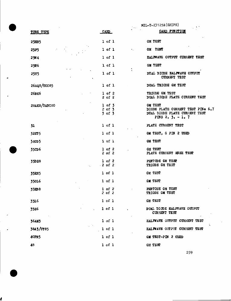
●TDSE TYFE
MGT-23 I 25A (SHIPS) $,gARDFURCII~J&L
lofl
lofl
23SS5
25P5
23W4
25W6
25Y5.
CM TEST
,, GM TSET
lofl
lofl
lofl
SAUWAVS OGTPWL’S0S!! TEST
CM TE9T
DUAL DIODE fLU~AVB 0WTP02CDRRE2?TTZSI’
26AQ8/VCC85
26BK6
lofl DUALTSIODE GMTEST
10f220f2
TRIODEGM TESTDUAL DIODE PLATECDRR2RTTEST
25AK8/DAscoo CM TESTDIODEPLATECDRREW2TESTPINs 6,7DUALDIODEPLATECORRENTTEST
PI17S2, 3, - 1, 7
31
32ZT5
34GD5
Iofl PLATECDRRERTTEST
CMTEST, G Pm 2 OS~
G!dTEST
lofl
lofl
lofz20f2● 352D6 GM TEST
PLATE CDRfWT E21EETEW
3X)28 lofz20f2
352s5 Iofl CM TEST
3!XL6 Iofl GM TES2
PESTOOEGM TESTTRIODECM TEST
35ES8
35L6
35z6
56Af63
3sA5/or85
4om5
48
10f220f2
lofl GMTEST
lofl DUAL DIODEEALRTAVE00TPI?ICOR.RE3TTE=
lofl SAUWAVE OU1’PWl’CORIIZUTTEST
lofl
lofl
lofl
EAIIWAVEOUPP’~CORWGT TEST
GM TZST-PfS2 OSED
GM TES2
259
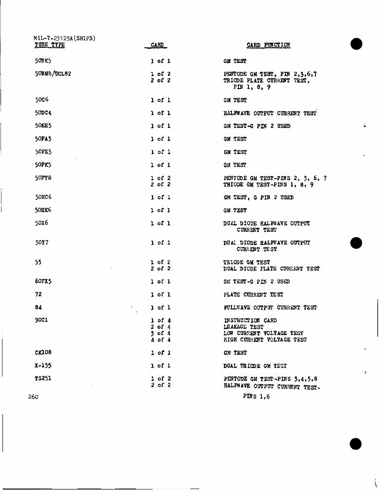
I
IMIL-T-23125A[SHIPS)TOSE TYPE
I 50SK5
50SM8fiCLE12
50C6
50DC4
50ss5
50PA5
5CPE5
50FK5
5oPYfl
I 50Kc6
50EK6
50X6
50Y7
55
60Px5
72
84
90C1
cS208
X-155
TS251
I 26o
lofl
lofz20f2
lofl
Iofl
lofl
lofl
102’1
lofl
lofzZofz
lofl
lofl
lofl
lofl
lofz20f2
Iorl
Iofl
lofl
10f420f4~of’1bof4
lofl
lofl
lofz20f2
IMm POSCfIOU
GM TE9T
PENYODEGM TE9T, PIX 2,>,6,7TSIODEPLATE C~FM21TTEsI..
PIN 1, 8, 9
GM TEST
SALFWAVE00TPOTCOSIWT TEST
CMTEST-0 PRl 2 m
GM TEST
GMTEST
GM TEST
PENTODEGM TEST-PISS2, >, 6, 7‘ffUODEGMTEST-PIXS1, 8, 9
GM TEST, G PIN 2 USED
CM TEST
DUAL DIODE SAL2WAVE00TPOTCUWWT TEST
DUAi DIODE SALFWAVE00TPUYCWLU3XTTSST
l?BIOOEGMTESTDUALDICDE IZATS CUW’T TES’I
CM TEST-GP2H 2 USSD
PUTE CVRRE21TTZST
PJIJJ:AVE00TPW Cnfi~T TEST
INSTSUCTIOXClifll)f,sAictm!fEsTLCW COS?MT VULTAOETES’TEICIIC~:~ VOLTACETEsT
GM T5sT
DUAL TSI~E GM TEST
PRiT~E GM TESP-PINS3,4,5,0SALWAVS00TPOTCmml?f mjw-
pflis 1,6

● nmETrm
292A
303A
307A
312A
347A
352A
3W
395A
502A
●CXS26AX
C2533AX
559
cK573Ax
629
713A
717A
W2A
807
w10f220f2
10f2Zofz
lefl
lofl
lofl
lofl
lofzZofz
1 0f,320f33of3
lofj20f330fj
lofl
lofl
lofl
lofl
lofl
10f320f330f3
10f220f2
lofz2 ef2
lofz20f2
iofl
lofl
MIL-T-23125A(SHIPS)
CARD Po21CTI~
mom a -PLATS 002umT TEm
TSIOD2 oilTESTDIODEPLATECUSRENTTEST
PUTS cLmRml TmT
DMT222
ammsr
PULL4AVS OUITWICDEiESTT2BT
221WEWTIM! CASD@’mm
IN92SUCTI~CASU91’A2iTk21VOLTA022DSOPA20D2VO~AGE DROP
CAT220DScussmv2TESTPLATETO CATEODEV02.IIAOETE91P2.4PEcussRv2cmn TEST
PRiTODES TSIO~ GM TSST
PLATScu2um?2TEsT
PLAT22CLM+E2PITEST
PLATECORmi’Tmm
PLATEcus2mT T2sT
CAT20DECUFRRV2TW2PLATSTO CATSOI&VOLTAOET~PLATECURRENTcuroFPTEST
CM TSSTPIW5 USEDUMTESTPI?i> USED
0MTDSTP125 USEDUMT292P1230SSD
TRIOD22PLAl%~ TESlTBIOD2AS DIODEPLATETO CAT20DE
VOLTAOE TEST
Oumm
PLATE cufmEn2 TmT 261
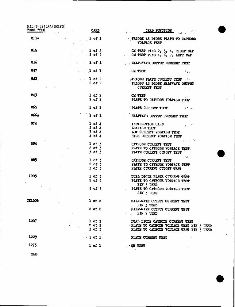
MIL-T-23125A(sHIP5)TOSETYPE
sllA,:
815,.
816 .,
837
.942
865
866A
W4
.994
S85
1005
02w%
100’I
1229
1273
262.
QA&
lorl
10f2Zorz
lofl
:1of 1
lof220f2
lofzZofz
lofl
iOfl
10f4Z0f430?440f4
10f J20f330f3
lof320f330f3
10f320f3
30f3
10f2
20f2
10f320f33of3
lofl
10?1
TRIODEAS DIODEP2&TliTU CATHODEVOLTAGE‘PEST
OM TESTP2N9 2, 3, 4, RIOETCAP02Al%STPINS4,6,7, LEPrCAP
EALP-WAm 00TPUTS0- TEST
,T2UODEPLATECOSUO?NTTE9T f~~TRXODEAS DIODEEALFWAVEOU1’PTYl
cU- T29T
OmTEsTPLATETO cATSODEVOLTACE&
PLATEODRsENPTEsT j.,
IliWSUCTI02?CAliD ,-LEAKAGE173sTW CURW2VIVO~AOE ~THIGH 00R52WfVOLTAGET2w
,1 . “’”Cimom CuRm2fPTE9TP2@2 TO CATROLEV02/lAOET&STPLATECURRSRTCOTOFVTEsT
CATRO?32CKC+5E2Wm ‘“PLATETO CATSODEVOLTAOEmPLATScoRRm?rCDTOPPT2sr
DUALDIODSPLATEC~ T&T;PLATETO CA~ODE VOLTAGET2W
P1215USEDPLATETO CATHODEVOLTACETEsT
PIU3USBD
EALV-WAV12O- CU- mP2213U9ED
RALV=AVEOUTPUPC02U@?lTESIPIN2 Um
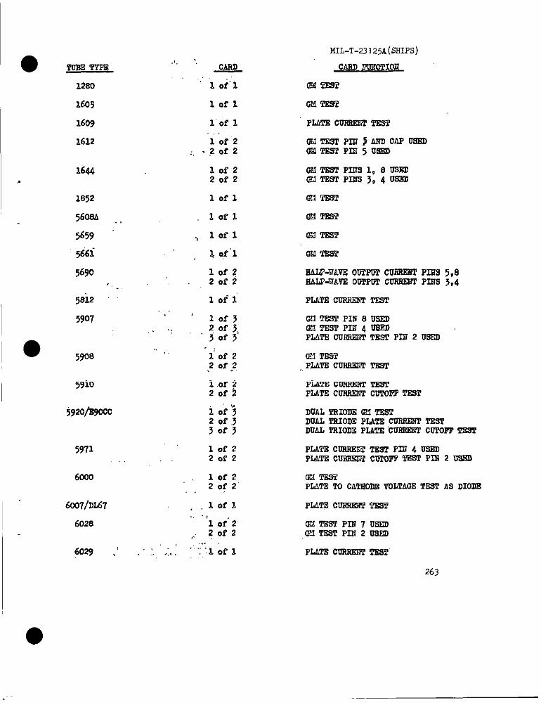
● ✎�✎Tus2TYPE
1644
1852
56OSA ,,
5659
5i6i
569o
● 5908
5910
5920/B900c
5971
6020
6c07/DL67
6028
6029 ,’ :. .:.
MIL-T-23I25A(SHIPS)
Wmw
PLATE cUrUIEETTSSl
G$JTDSTPIN 3AKDCAPUSEU@MTsS2Pm5u5D
W?TESTPIITS1,8UWDlmTEsTPms304u9m
GH’mm
OM’rml
C13TSSI
OM 53s?
SAW-WAVE00ITUfCUSREilTP2M9 5,8EALP-WAVEOCTP~C~ PIHS3,4
PLATDCUSSESTTEST
Clf TEST PIS8 USEDc%llTEsTP12J4u5sDPLATE CUFMEFTTEST PIE 2 USED
u?lTEsT,PLATSCUSSSMTT’m2
PLATE CORSE2?2T2sTPLATS COSSSIWCuTom TEsT
DUALTSIODECM TsSTDUALlTIIODEPLATECUSRE3TT!3STDUALTSIODEPLATE“CU2RERTCWPOPFTSST
PLATDcusFc+mTEm Pm 4 UmPINPSCussmwCUTOFFTEs’rPss 2 UssD
OMTEWPIJM!ETO CATHODEVOLTAGETESTAS DIODE
PLATRcurtsLnTTEST
cMTEsTPIN70sED,O?iTESTPIR 2 USED
PLATECORSE2FPTEST
263
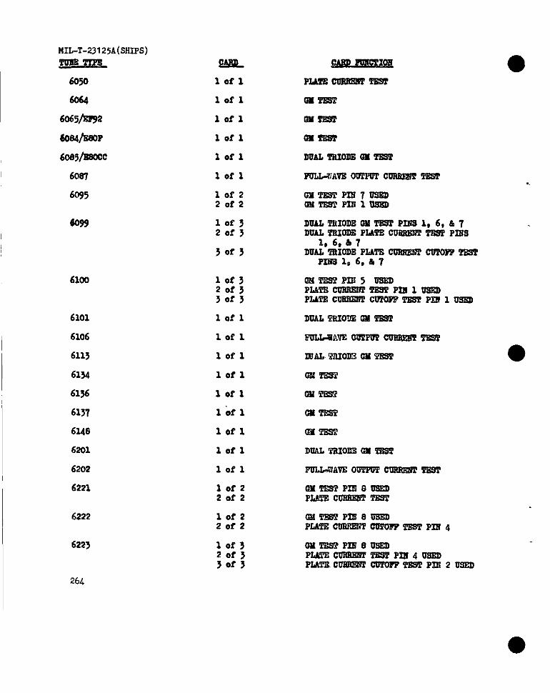
MIL-T-23125A(SSIPS)
‘Fwz=2Jrm
6050
w
6065~2
6os4/sBoP
60S5/ESWC
60s7
6095
6100
6101
6106
6113
6154
6136
6137
6u8
62o1
62o2
6221
6222
622>
WIL
lofl
lofl
lofl
lofl
lofl
lofl
10f220f2
lof~20f3
30f3
lof32Df330f3
lofl
lofl
lofl
lofl
lofl
lofl
lofl
lofl
lofl
lofz20f2
10f220f2
10f320f350f3
WWQ!2
PLAm2DRssm2’2ssT
D22ms’i!
Dn’fml
Qxmsi
DuALmIollsum’m2m
PoLL=A~ OVITOTC~ ~
oMTssTPm7usmaMT6sTPnJlusm
DUANliIODBGSa=PIZiSl ,6,&7DUALTBIODEPL4TS2uSsSl?rmsf PR2S
1,6, b7DUALTRIODEPIATECUSSE6TCWPOF7-
PIB31,6,.S7
@A’llzSi?PIE5mPLA’A’220usB5TT129rPn21mPLATscusrlEnTclnoJ?TS9PPxElussD
DUAL‘ITIIODSCM m
6iJW=SAVEW2PO?~TSS3
123AL?aIOlrBc22TEs’r’
0MTE2T
w-
GH TWf
Q.MTS22
DUALmoi2s cm ms2
FULIDWAVE0UTPF72URRWW2TSST
@i22EsTrJIl?c+ossDPLATECollsmrTEST
OM’rEs’lm80s2DPLATEcusssiWOvPOFFTAWP2224
GXTWf PIt?eusEDPLATD2USSEETTEST PIU40SQPldmclJEBEsTcs%OrPf%s2m2 usEn
●
26L
●
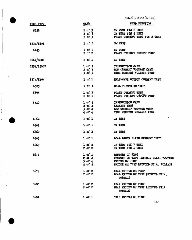
I_
1’,-
6225
6221/EsoL
6245
6267/EPa6
6354/150S2
6374/EY84
6542
● 6660
6661
6662
6663
6669
6678
6679
66eo
66s1
10f320s330f3
lofz20f2
Iofz20f2
Iofl
MIL-T-23125A(sSIPS)
CARD J3J2k7fICLS
@2iTSSTPni8ussDGMTESTP12s4usi2DPLATs.cmwlEsPfTrWrP22i2 usEn
m-lwr
@24TEsTPLAmCusRQvfmm TmT
mm
121STSU6TIOSiCASD2.0?7COSRRiTVOLTAOETESTmm CIlsmm VOUPAOE‘mm
EALWUAW+ 00TPWilCOSSESTTXiT
DUALVSIODE@l TWf
PLATEculU@liTWASPPmm cIOOiEHTOWrOPFTsss
E%9PSUCTIOI?CARDLm.KAoEms’rUIW OUSRBSTVOLTACETESTXOIIQUW@Pf VOLTAOETEST
Ims’PEs?
Lm’mm’
CM’PEm
DOAL1210DEPLATE CUSSENTl12ST
Pi2mDEcnmsTPPWPODEW T29TSEDUCEDPILA.VOLTACETRIODDCM’FESTTSIODSW TSSTSEDDCEDPILA.VOIICACS
DVALTsIODSGMTESTDUAL9sIODROHTESTS3DVCETIFILA.
VOLTAGE
DOALTPtW21E622TsSTDUALTSIODECM TESTSEDWEllFILA.
VOLTACE
DOAL TsIODECM TFL9’f
265
●
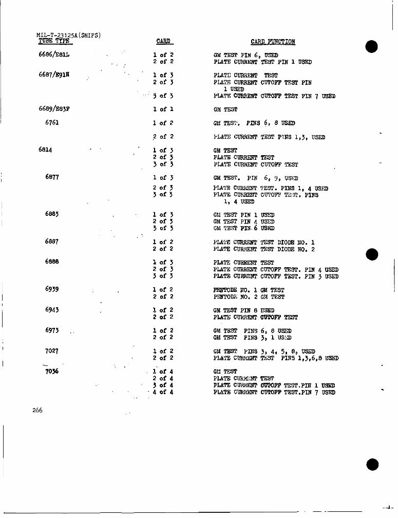
F#&T-#5A(SHIPS)
6686&lL
6687/s9Nl
6761
6814
687’I
6887
6888
6939
6943
6973
7027
7036
266
WL
lofz20f2
lofj20f3
~of>
lofl
10f2
Zofz
10f3Zofs>0f3
10f J
zof~30f5
10f3Zof>30f>
IofzZofz
10f320f330f3
IofzZofz
Iofz20f2
IofzZofz
10f220f2
i0f420f430f440f4
I
4X-2TEST PIN 60 USEDPLATECUFRSNTTEsrPIN 1 USED
PLATECURSE3T ‘PESTPLATECUSRENTcUTOPFTSS2 PIN
1 WEDPLATEoOTW6NTCUTQNFTEST PIN 7 USND
OM TEST
CM TEST. Pnis 6, 8 USED
I’LATNCUNSEWPTNST PIIJS1,3,USED
GM TESTPLATECURSESITTESTPLATXCINO@liTCUTOFPTEST
GM TNST. PIN 6, 9, USICI
[email protected] 1, 4 USEDPIATECUF.S3NTcUTOFTTAM’.PINS
1, 4 USXII
GM TNSTPIN 1 TJ3EDR6TEsf PIN~usEDGM TESTPIN.6 USED
PLATECORSENTTEST DIODNNO. 1PLA?ECUSJi132fTTNSTDIODENO. 2
●PLATECNSSERITESTPLATECONRJE4TCOTOPPTEST.PIN 4 NSEDPIATECU8SENTc~OFF TEST.PIN 3 USED
PEWTODE2?0.X OM TNSTPENTODENO. 2 G!lTEST
GM TEST PIN 8 LISEDPLATSCu-tlsmONTw’PTEST
GM TEST PINs 6, 8 USNDOM TEST PINS 3, 1 USXD
GMT8ST PINS3, 4, 5, 8P USEDPLATECNSRSWPlWSP PINS1,5,6,s U=
GM TESTPLATECWIPP [email protected] 1 USSDPLATNCU8RNNTCUTOFFTNST.PIN7 Osm
-4-
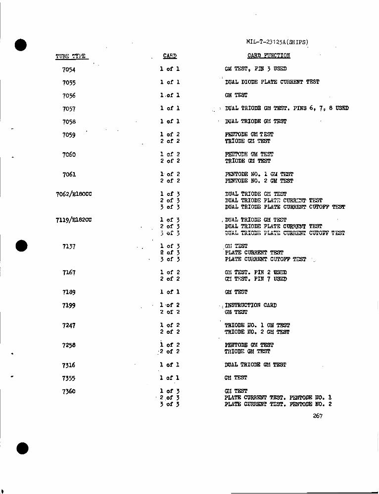
TIJ?ETYPE
7054
7055
7056
7057
7058
7059 ‘
7060
7061
Q@
lofl
lofl
l.of1
lofl
lofl
lofz20f2
Iofz20f2
1 of 220f2
7062/EIOOCC
7119/E18200
7167
7189
7199
7247
7258.
7316
7355
7360
lofjQ0f3
10f220f2
lofl
1 of 220f2
10f220f2
i0f2,2 of 2
Iofl
lofl
10f32.0f33of3
MIL-T-23125A(9IIPS)
Gb!TEST,FIR 5 US2J)
DUALDIODSPLATE CUFRERT~T
GM TE6T
: DUALTRIODEGMTEST. PIl?S 6, 7, 8 DSRD
DUALTSIODEOH TEST
PENTODEGM TESTmom G’JTRsT
PmTom OIAmmTsIODE6X ‘PEST
PF2PPODENO. 1 GldTESTPEMTODEI?0.2GMTEST
DUALTSIODECll TESTDUALTRIODEPLUT CCOOC3TTESTDUALTRIODEPLATE CURWWTCIJTOPPTF9T
,DUALTSIOIE@i TESSDUALTSIODEPL4TECOEKE!TTR9T‘JUALTRIODEPLATECURRIWfCWPOFFTEST
G!JTFSTPL4TE cUSRmT TESTPLATECUiWEliTCbTOPF‘PEE
CM TEST.PIN 2 US~OMTEST. PIN7 USED
(NJTEST
.: INWPSUCTIONCASDw TEST
TsIODEIJO.1 CM TESTmom No. 2 CM TRsT
PmToDE QATE9TTRIODE(W!TSSP
IUJALTSIODSOM TEST
w! TEST
0?3TESTPLATECUSREWITEST.PENTODR2J0.1PLATRcuFroINTTzST.mm Eo. 2
267

MILeT-23125P.(sSIPS)TUSETTPS
1370
1408
7554b150L
7545
7551
7558
7581
7586
7587
7591
7643h~F
7607
I7693/~
7694/E99?
7695
76w
7701
7716
7717
7719
7722/S260i+
7724
268
QIQ
let220f2
10f220f2
lofl
lofl
10f22of2
lofzZofz
lofl
Iofl
lofl
10f220r2
10f220f2
10f220f2
lofl
lofl
lofl
10f22of2
lofl
10f220f2
lofl
lof22.af2
1 ‘of1
10f22ef2
&4iUlI)LW’IION ●DUALTAIODSGM‘21?STDUALTSI~ PLAIT!CUFOWWPTSST
w-PwTE cDsr&2wF21FxTsul
OM TEST
OMlzm
GMTss PINS8, 9 UsmPLr2Ecmwmm’msTPINsl,30sm
0UTESTPIN8,90SEDPLATECUSSENTTEST PINS 1, j USED
GNT2ST
GM TEST
ON TEST
fJMTmTPIN8mPLATE CUBR12?2TSST PIN 4 OSEU
PmmDEoMTEsTTsIODEOMTSST
PEMPODEGM TESTTSIODS~ ‘PSS2
OMTWP
Gmmm
FENPOXISNO. 1 GM TBPPF2iToml?o.2oMTEsT
GM TEW’.PINsl,7usLll
TSIO~ ~ TESTFEUTODSGM TEST
OMTSST
0MTE2T.PIEs6,7USE3FLV2ECUSRZtWTESTPIB 1, 2 USIZl
GXT2STPIIilu9ml
TSIODSGU TSSTDUALDKK4?FIATECORRENP-

MIhTm23125A(SHIPS)
~
Iofl
lofl
CARD FOiCC’TIOi4
DUAL TRIODEGM TEW7728
?729
7730
?751
DUAL TRIODE6SITSST
Iofl DOAL TTiIODE62iTESS
10f220f2
~ToDE GM TESTT21@E 6A!TEST
GM TEST7732
7733
7794
lofl
lofl
10f420f4s0f44of4
Cl!TEE5
P22JTODEGM TESTTRIOJIEGM TiSTTRIODEPLATEC020@iTTESTTRIOOEPLATE CUSHE22TCUTOFFTEST
7737/sls61? 10f2Zofz
G!.fTESPIN5UREDPLATECDRRKW T.E?T-PZW1 USED
7154
7759
Iofl W T2ST
lofzZofz
DUAL TRICDIiGM T.2SFDUAL TRIOI)EFLATECD2..SXT
CUTOFFTE91
. 7760
7761
lofl
lofl
DUAL T210DEW TEST
GM TEST
7762 lofsZofjj0f3
Q!iTES2-P22+8 US~PLATECORFJXTTEST-PIM4 USQPLATECORREXTCUTOFFTEST
778S/R810P
7802
lofz20r2
CM TERTPLATEC0f152sTTEST
DU.4f,TRIODEGM TIL5TDUAL TRIODEPLhTETO CATRODE
VULTACE~=Dm TRIODEPLATE ~
COTOFFTEST
10f320f3
30f3
DUM, TRIODEGM TEST. 7861
7867.
7e’se
lorl
lofl DOAL TIIODE GM TEST
10f2Zofz
GM TEST PLh’S2, 7 u2~PLATECDRFJ21TTEST P2!w 1,6 Usm
7ss9 10f2Zofz
DUALTifIODE CMTESTDUALTRIODEFLATE IX’S.F=L’ CDTOFP
269 TE51!
—

MIL-T-23 125A(SHIPS)TUEE TYPE
7895
7890
7905
8016
@256
8058
8102
8106
CASD FOXCTIC24
lofl GM T.EST ,.
lofl DOAL TSICTJEGM TE91
PLATECUSSE2?TTEST, PIi? 8 IJSI%O
lofl PLATE CDSSENTTEST
GM TESTlofl
10f220f2
IRSTRUCTIOSCAI?DGM TEST,Px!i2 USED
lofz20f2
lofl
PmToDE CM TESTTBIODEGM TEST
GM TEsT,PINs 8, 9 USF.O
8185 lofl GM TEsT, PIN 7 USED
GMTEsT, Pm 7 USSXI8106
DC90
E82cc
E92CC
EAA91
Es91
ECC81
ECC83
ECF83
ECF804
ECE35
EF91
lofl
lofz20f2
PLATE COSS2NTTE92, PINS 3,3 USEDPL&TECDILSENTTESI, P211S2,6 USED
lofl DUALTBWDE GMTEST
10f3 DUALTEIODE OCJTESTDUAL T2110DEPLATE CUSRiU{TTESIDUAL TRIODEPLATE COSN2NT ●
CUTOFF TEST
20f330f3
lofl DUAL DIODE PLATE COSRSNTTEST
lof 1 DUAL DIODEPLATE CURIIRiTTE91
DUAL TSIODECM TEsTlofl
lofl DUAL TRIODEOklTSST
10f22of2
PENTODEGM TEST‘PSIODEGM TE5T
lofzZofz
FENTODEGM TESTTBIODEGM TEsT
10f2
20f22f2iTODEQM TESTTSIODEGM TBST
lofl w T2!sT
I 270
I—

TOSE TYPE
EFW4
SL>7
EL821
EL822
EZ90
Gz>2
GZ33
mr61
ST66
Icrt%
UIW9
W77
z729
1OI-1
lafl
lofl
lofl
lofl
lofl
lofl
lofl
lofl
lofl
~of~
lofl
lofl
MIL-T-23125A(SHIFS)
CAFD FoRcTIOW
CM TEST
GM TEST
GM TEST
O!,lTEST
FOLLWAVE00TPoTCUSIWT TESI
FOLLWAVX00TPITlCOSHINTTES2
FOLLWAVE0W2POTC~~T TEST
GM T&sT
GM TEST
CM TEST
CM TEST
GM TEST
GX TEST
271
oPFtcluUwaus●cauw mm HIWATK Ua UOO
Commander, Naval Ship Engineering CenterCode 6124, Center BuildingPrince Ceorge’s CenterEyattsville, ND20782
POul
..
‘
I ●
I
I
I‘[
OMB APP3v.1N., 22.R255
1NSTRUCTIONS The purpose o{ this form is to solicit beneficial comments which will help achieve CIrocure-ment of suitable products at reasonable cost and minimum delay, or will otherwise enhance use of the document.DoD contractors, ~overnment activities, or manufacturers/ vendors who are prospective supplier. of the product.,. invited to submit comments to the govemme.t. Fold on lines on reverse side, staple in corner, a.d send toPr.p,.ri. g activity. C.mme. t. submitted on this form do not c..sti:ute or imply authorization to waive ..YP.rt:.n of the :. f.r...ed d..ume. t(.) of to amend c..tr..l..l rewreme.ts. Attach any pertinent data whichmay be of use M improving this document. If there are additional papers, .Itach to form and place both M anenvelope addressed to preparing activity.
,OC” MENT ,oENT, F,ER AND TITLE
IAME OF ORGANIZATION AND ADDRESS CONTRACT NuMBER
MATERIAL PROCURED UNDER A
D ‘lRECT cOv ERNMENT CoNT:.ACT m $. B. O. TR.CHAS ANY PART OF THE DOCUMENT CREATED PROBLEMS OR REQUIRED INTERPRETATION IN PROCUREMENT
USE7
A. .,”. PA RAG. APW N.Me ER ..0 WORDING
COMMENTS ON ANY DOCUMENT REOUIREMENT CONSIDERED TOO RIGID
IS THE DOCUMENT RESTRICTIVE?
D ,.s rJ No (u w-..-, 1. hat way?>
JBMITTED BY (Prl”t.d ., ,W.d .m. and &ldr..e - OPtlOml) TELEPHONE No,
DATE