MIH4.2ESDX 50Hz - Generac Mobile Products
28
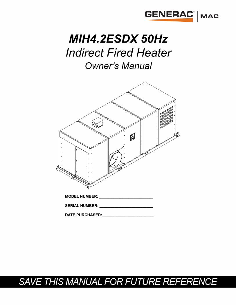
SAVE THIS MANUAL FOR FUTURE REFERENCE MIH4.2ESDX 50Hz Indirect Fired Heater Owner’s Manual MODEL NUMBER: _________________________ SERIAL NUMBER: _________________________ DATE PURCHASED:________________________
Transcript of MIH4.2ESDX 50Hz - Generac Mobile Products
SAVE THIS MANUAL FOR FUTURE REFERENCE
MIH4.2ESDX 50HzIndirect Fired Heater
Owner’s Manual
MODEL NUMBER: _________________________
SERIAL NUMBER: _________________________
DATE PURCHASED:________________________

ii Owner’s Manual for Indirect Fired Heater
(000004)
WARNINGCalifornia Proposition 65. Engine exhaust and some of its constituents are known to the state of California to cause cancer, birth defects, and other reproductiveharm.
(000005)
WARNINGCalifornia Proposition 65. This product contains or emits chemicals known to the state of California to cause cancer, birth defects, and other reproductive harm.

Table of Contents
Section 1: Introduction and SafetyIntroduction ..................................................................1
Read This Manual Thoroughly ....................................1
Safety Rules .................................................................1How to Obtain Service .................................................1
General Hazards ...........................................................2Explosion and Fire Hazards ........................................2Electrical Hazards ........................................................2Safety and Operating Decals ......................................3
Section 2: General InformationSpecifications................................................................5Component Locations ..................................................6Control Panel.................................................................7Fuel System ..................................................................8Electrical Connection ..................................................8
Section 3: OperationTheory of Operation .....................................................9Placement .....................................................................9Before Starting .............................................................9
Pre-Start Checklist .......................................................9
Ducting Guidelines ......................................................9Heater Startup ..............................................................9
General Overview ......................................................10Operational Procedure ..............................................10
Adjusting Heater Output ............................................10Thermostat .................................................................10
Thermostat Control ....................................................10
Heater Shutdown .......................................................11Emergency Shutdown ...............................................11
Section 4: MaintenanceMaintenance ...............................................................13Maintenance Tasks ....................................................13
Daily Walk Around Inspection ....................................13
Maintenance Schedule ..............................................13Maintenance Schedule...............................................14
Other Maintenance Checks .......................................14
Section 5: TroubleshootingGeneral Troubleshooting Guide ................................15
Section 6: Installation DiagramsBlower Panel (1 of 2)...................................................17Wiring Diagram ...........................................................19
Owner’s Manual for Indirect Fired Heater iii

This page intentionally left blank.
iv Owner’s Manual for Indirect Fired Heater

Introduction and Safety
Section 1: Introduction and SafetyIntroductionThank you for purchasing a Generac Mobile Products,LLC product. This unit has been designed to providehigh-performance, efficient operation, and years ofquality use when maintained properly.The MIH4.2ESDX 50Hz indirect air heater is designedand built for sustained, reliable heat production inindustrial operating conditions and environments. TheMIH4.2ESDX 50Hz is built to withstand frequent handlingunder these conditions. The fully enclosed designprotects the operating components, allowing all-weatherstorage and operation.The information in this manual is accurate based onproducts produced at the time of publication. Themanufacturer reserves the right to make technicalupdates, corrections, and product revisions at any timewithout notice.
Read This Manual Thoroughly
If any section of the manual is not understood, contactyour nearest Generac Mobile Products (GMP)Authorized Service Dealer (ASD), or contact GeneracMobile Products Customer Service at 800-926-9768, orvisit http://www.generacmobileproducts.com with anyquestions or concerns.The owner is responsible for proper maintenance andsafe use of the equipment.SAVE THESE INSTRUCTIONS for future reference. Thismanual contains important instructions for the unit thatshould be followed during installation, operation, andmaintenance of the unit. ALWAYS supply this manual toany individual that will use this unit.
Safety RulesThe manufacturer cannot anticipate every possiblecircumstance that might involve a hazard. The alerts inthis manual, and on tags and decals affixed to the unit,are not all inclusive. If using a procedure, work method,or operating technique that the manufacturer does notspecifically recommend, verify that it is safe for othersand does not render the equipment unsafe.Throughout this publication, and on tags and decalsaffixed to the unit, DANGER, WARNING, CAUTION, and
NOTE blocks are used to alert personnel to specialinstructions about a particular operation that may behazardous if performed incorrectly or carelessly. Observethem carefully. Alert definitions are as follows:
NOTE: Notes contain additional information important toa procedure and will be found within the regular text ofthis manual.These safety alerts cannot eliminate the hazards thatthey indicate. Common sense and strict compliance withthe special instructions while performing the action orservice are essential to preventing accidents.
How to Obtain ServiceWhen the unit requires servicing or repairs, contact aGMP ASD for assistance. Service technicians arefactory-trained and are capable of handling all serviceneeds. Go to http://www.generacmobileproducts.com/parts-service/find-service for assistance locating adealer.When contacting a GMP ASD about parts or service,always supply the complete model and serial number ofthe unit as given on its data decal located on the unit.Record the model and serial numbers in the spacesprovided on the inside front cover of this manual.
(000100a)
WARNINGConsult Manual. Read and understand manualcompletely before using product. Failure to completely understand manual and productcould result in death or serious injury.
(000001)
DANGERIndicates a hazardous situation which, if not avoided, will result in death or serious injury.
(000002)
WARNINGIndicates a hazardous situation which, if not avoided,could result in death or serious injury.
(000003)
CAUTIONIndicates a hazardous situation which, if not avoided,could result in minor or moderate injury.
Owner’s Manual for Indirect Fired Heater 1

Introduction and Safety
General Hazards Explosion and Fire Hazards
Electrical Hazards
WARNINGRisk of injury. Do not operate or service this machine if not fully alert. Fatigue can impair the ability to service this equipment and could result in death or serious injury.
(000215)
CAUTION
(000291)
Equipment damage. Do not attempt to start or operate a unit in need of repair or scheduled maintenance. Doing so could result in serious injury, death, or equipment failure or damage.
WARNING
(000107)
WARNINGHearing Loss. Hearing protection is recommended when using this machine. Failure to wear hearing protection could result in permanant hearing loss.
(000111)
WARNINGMoving Parts. Keep clothing, hair, and appendages away from moving parts. Failure to do so could result in death or serious injury.
(000108)
WARNINGHot Surfaces. When operating machine, do not touch hot surfaces. Keep machine away from combustibles during use. Hot surfaces could result in severe burns or fire.
(000377)
WARNINGVision loss. Eye protection is required when servicing unit. Failure to do so could result in vision loss or serious injury.
CAUTION
(000229)
Equipment or property damage. Do not block air intake or restrict proper air flow. Doing so could result in unsafe operation or damage to unit.
(000105)
DANGERExplosion and Fire. Fuel and vapors are extremely flammable and explosive. Add fuel in a well ventilated area. Keep fire and spark away. Failure to do so will result in death or serious injury.
(000147)
WARNINGRisk of Fire. Unit must be positioned in amanner that prevents combustible materialaccumulation underneath. Failure to do socould result in death or serious injury.
(000145)
DANGERElectrocution. In the event of electrical accident, immediately shut power OFF. Use non-conductive implements to free victim from live conductor. Apply first aid and get medical help. Failure to do so will result in death or serious injury.
(000104)
DANGERElectrocution. Water contact with a power source, if not avoided, will result in death or serious injury.
(000152)
DANGERElectrocution. Verify electrical system isproperly grounded before applying power.Failure to do so will result in death or seriousinjury.
DANGERElectrocution. Do not use unit if electrical wiring is cut or worn through. Doing so willresult in death or serious injury.
(000378)
(000155)
WARNINGOnly a trained and licensed electrician should performwiring and connections to unit. Failure to follow properinstallation requirements could result in death, seriousinjury, and damage to equipment or property.
2 Owner’s Manual for Indirect Fired Heater

Introduction and Safety
Safety and Operating DecalsSee Figure 1-1. This unit features numerous safety andoperating decals. These decals provide importantoperating instructions and warn of dangers and hazards.The following diagrams illustrate decal locations anddescriptions.Replace any missing or hard-to-read decals and use carewhen washing or cleaning the unit. Decal part numberscan be found in the parts manual, available at http://www.generacmobileproducts.com.
ID Description
A Hot Surface Warning: Do Not Enter Intake
B Diesel Fuel Hazards
C Ultra Low Sulfur Fuel Only
D Moving Parts: Do Not Remove Screen
E Lifting Eye/Tie-Down Location: Right
F Forklift Pocket Location
G Lifting Eye/Tie-Down Location: Left
H Keep Doors Closed
I Thermostat Instructions
J Operating Instructions
Owner’s Manual for Indirect Fired Heater 3

Introduction and Safety
Figure 1-1. External Decals
004791
J
THERMOSTAT CONTROL1. PRESS AND HOLD MENU UNTIL DISPLAY CHANGES TO “SP”.2. PRESS UP AND DOWN ARROWS TO REACH DESIRED FUNCTION. SP - SET POINT TEMPERATURE DIF - DIFFERENTIAL TEMPERATURE Example: SP is at 180 and DIF is at 10 Temperature will rise to 180 , shutting off burner. The heater cools to 170 , turning the burner back on.3. PRESS MENU TO DISPLAY FUNCTIONS CURRENT VALUE.4. PRESS UP AND DOWN ARROWS UNTIL DESIRED VALUE IS REACHED.5. PRESS MENU TO SAVE NEW VALUE. DISPLAY RETURNS TO SENSOR TEMPERATURE.
NOTE: PRESS MENU AGAIN TO SAVE THE NEW SETTINGS!
I
KEEP DOORSCLOSEDDURING
OPERATION
H
G
E
F
DANGERGEFAHRPELIGRODANGER
DIESEL
CULTRA LOW
SULFUR FUEL ONLYB
G
E
F
A
A
F
D
4 Owner’s Manual for Indirect Fired Heater

General Information
Section 2: General InformationSpecifications
Heater 4,225,500 BTU/hr (1,238.4 kW/hr) maximum
Type Indirect fired
Power 30 hp electric motor
Fan Operating Speed 1,460 rpm
Air Volume 21,000 CFM (35,679 m3/hour)
Static Pressure 3 in H2O (0.75 kPa)
Air Outlet 36 in (91.4 cm)
Electrical 380V, 50Hz incoming line
Burner Riello, RL 130/M
Burner Type 2 Stage/modulating
Burner Fuel Diesel
Fuel Tank Capacity 160 gal (606 L)
Burner Fuel Rate (at 100% prime) 31.3 gph (118 Lph)
Total Maximum Run Time 5.1 hrs
Temperature Rise 180 °F (82 °C)
Fan Class 2, SWSI, 300 BC
Duct Diameter 36 in (91.4 cm)
Maximum Duct Length 30 ft (9.1 m)
Estimated Heater Efficiency 85%
Dimensions 289 in x 102 in x 118 in (7.34 m x 2.59 m x 2.99 m)
Weight 14,260 lbs (6,468.2 kg) operating weight, skid mounted
Owner’s Manual for Indirect Fired Heater 5

General Information
Component Locations
Figure 2-1. External Component Locations
A Exhaust stack E Forklift pocketB Fan access door F Diesel fuel fillC Lifting eye G Air outletD Air inlet H Burner access door (not shown)
004615
A
B
C
CD
F
G
C
E
E
H
6 Owner’s Manual for Indirect Fired Heater

General Information
Control Panel
Figure 2-2. Control Panel Component Locations
A Main power disconnect switch D Fan on/off switchB Reset button E Lights on/off switchC Burner on/off switch
!
004790
RESETLIGHTS FAN BURNER
OFF ON OFF ON OFF ON
Arc Flash Hazard.
Appropriate PPE Required.
Failure to Copmly Can Result In Death or Injury.
Refer to NFPA 70E.
On
Off
Reset
Trip
A
B
C
D
E
Owner’s Manual for Indirect Fired Heater 7

General Information
Fuel System
This burner is designed to operate with diesel fuel.
NOTE: Comply with all laws regulating the storage and handling of fuels.
Follow these guidelines:• Use ultra-low-sulfur diesel fuel only.• When temperatures are at or below freezing, use
No. 1D diesel fuel.• When temperatures are above freezing, use No.
2D diesel fuel.• In some areas of the country, climatized fuel—a
mixture of 1D and 2D—may also be used.
Electrical Connection
IMPORTANT NOTE: The unit is powered with threeline power cables routed through the incoming elec-trical port and connected to the distribution block in-side the control panel. Incoming power must be 380V50Hz.IMPORTANT NOTE: Inrush amperage to start theblower is 237A at 57kW. Amperage will drop to oper-ating levels once fan is running.
(000168)
DANGERExplosion and Fire. Fuel and vapors are extremely flammable and explosive. Keep fire and spark away. Failure to do so will result in death or serious injury.
(000204)
DANGERExplosion and Fire. Do not overfill fuel tank. Overfilling may cause fuel to leak and ignite or explode, resulting in death or serious injury.
(000145)
DANGERElectrocution. In the event of electrical accident, immediately shut power OFF. Use non-conductive implements to free victim from live conductor. Apply first aid and get medical help. Failure to do so will result in death or serious injury.
DANGERElectrocution. Do not use unit if electrical wiring is cut or worn through. Doing so willresult in death or serious injury.
(000378)
(000152)
DANGERElectrocution. Verify electrical system isproperly grounded before applying power.Failure to do so will result in death or seriousinjury.
(000155)
WARNINGOnly a trained and licensed electrician should performwiring and connections to unit. Failure to follow properinstallation requirements could result in death, seriousinjury, and damage to equipment or property.
8 Owner’s Manual for Indirect Fired Heater

Operation
Section 3: OperationTheory of OperationWhen the thermostat is set at a temperature, the indirectheater generates heat when the burner unit is turned on.This combustion heats the blast box, and the hot air thenradiates through the transition. A fan pulls cool airthrough the intake and pushes it over and through theheat exchanger. The heated air flows out of the dischargeand through the ducting.
Placement• Unit must be placed on firm, flat, dry ground.• Do not place unit on an incline.• Use the lifting eyes and proper lifting equipment to
move the unit.• Do not operate unit on a flat bed trailer or transport
device.• Place unit a minimum of 10 ft (3 m) away from
structures and barricades.
Before Starting
Pre-Start Checklist
• Remove all flammable materials and fire hazardswithin 10 ft (3 m) of the unit.
• Keep unit a minimum of 10 ft (3 m) from structuresor barricades.
• Inspect inside and outside the unit for leaking fuel.• Verify the following are clear of debris and obstruc-
tions:– Burner air intake– Exhaust stack– Outlets and fan intakes
• Verify air duct hose is securely fastened to outletduct assembly.
• Inspect fuel supply assembly for proper installationand security.
• Verify fuel valves are open.• Verify tank return line is clear of obstructions.• Verify burner mounting system is secure.
• Inspect electrical wiring, components, and controlsfor abnormalities.
• Verify all burner and fan compartment electricalswitches and disconnects are OFF.
• Verify fan motor mount security and alignment.• Inspect fan shaft and bearing for security and
proper installation.
Ducting Guidelines
• Place ducting in desired configuration before oper-ating unit. Tightly secure ducting end to outlet.
• Avoid sharp bends or 90° turns in ducting.• Verify that ducting is not a high traffic area, and will
not impede workers or other machinery. Careshould be taken to prohibit the need to step orclimb over ducting.
• DO NOT place ducting over combustible materials.• DO NOT place ducting over surfaces that may
damage it or reduce performance, such as water,sharp rocks or glass, electrical wiring, and piping.
• DO NOT place or drape anything over ducting suchas covers, insulation, blankets or cloth, electricalwires, etc.
Heater Startup
(000108)
WARNINGHot Surfaces. When operating machine, do not touch hot surfaces. Keep machine away from combustibles during use. Hot surfaces could result in severe burns or fire.
WARNINGBurn hazard. Do not remove ducting until all air pressure has been emptied from hose duct. Failure to do so could result in severe injury.
(000288)
(000145)
DANGERElectrocution. In the event of electrical accident, immediately shut power OFF. Use non-conductive implements to free victim from live conductor. Apply first aid and get medical help. Failure to do so will result in death or serious injury.
DANGERElectrocution. Do not use unit if electrical wiring is cut or worn through. Doing so willresult in death or serious injury.
(000378)
Owner’s Manual for Indirect Fired Heater 9

Operation
General OverviewHeater and fan behavior are driven by several user-defined benchmarks. The fan starts when the fan motorbreaker and fan motor switch are ON.
Operational Procedure1. Place ducting in desired configuration.2. Make all necessary electrical connections to power
the unit.3. Perform walk around inspection; verify blower
intake and burner chimney are clear.4. Open fuel supply and return valves.5. Turn main power disconnect switch to ON.6. Turn fan switch ON.
IMPORTANT NOTE: Fan must be started beforeburner is started.
7. Turn burner switch ON. Wait for purge cycle tocomplete and watch for burner ignition.
8. Adjust high and low temperature settings on ther-mostats.
9. Close all access doors while unit is operating.
IMPORTANT NOTE: All doors on the unit must beclosed when operating.
Adjusting Heater OutputHeater output is adjusted using the up and down arrowson the thermostat to set the desired temperature.
ThermostatThe thermostat is located inside the burner access door.Record the set temperature for future reference.
Figure 3-1. Thermostat Features
Thermostat ControlProceed as follows to access the advanced menu andedit operating parameters, such as temperature units.
1. Press the MENU button.2. Press the up or down arrow buttons to reach
desired function.3. Press the MENU button to display the current value
of the function.4. Press the up or down arrow buttons until desired
value is reached.5. Press the MENU button to save the new value. The
display will show the next parameter code.6. Press and hold the up and down arrow buttons to
return to the main screen.
NOTE: If the MENU button is not pressed after changingthe function value, the new value will not be saved.
(000152)
DANGERElectrocution. Verify electrical system isproperly grounded before applying power.Failure to do so will result in death or seriousinjury.
(000108)
WARNINGHot Surfaces. When operating machine, do not touch hot surfaces. Keep machine away from combustibles during use. Hot surfaces could result in severe burns or fire.
CAUTION
(000291)
Equipment damage. Do not attempt to start or operate a unit in need of repair or scheduled maintenance. Doing so could result in serious injury, death, or equipment failure or damage.
WARNING
CAUTION
(000229)
Equipment or property damage. Do not block air intake or restrict proper air flow. Doing so could result in unsafe operation or damage to unit.
A Temperature offset indicator
B Temperature units indicator
C Operating mode indicator
D Liquid Crystal Display (LCD)
E MENU button
F Up arrow button
G Down arrow button
H Output relay status indicator LED
MENU
FBIN°
004794
A
D
E
F
H
G
B
C
10 Owner’s Manual for Indirect Fired Heater

Operation
NOTE: If no buttons are pressed for 30 seconds whileprogramming the thermostat, the display returns to thedefault temperature display. Any changes made are notsaved.
See Table 3-1 for thermostat functions.
NOTE: See thermostat manual for more information.
Heater Shutdown1. Turn burner switch to OFF.2. Allow five minutes of fan operation for cool down
cycle, then turn fan motor switch to OFF.
NOTE: Turning the fan off before the burner has cooledcould result in shorter burner unit life.
3. Turn fan switch to OFF.4. Turn main power disconnect switch to OFF.5. Close fuel supply and return valves.6. Detach ducting and return to storage.7. Close and secure access doors.
Emergency ShutdownRemove power at the incoming power source for the unitin emergency situations.
Table 3-1. Thermostat Function Ranges and Settings
Function Range Factory Setting
On = Relay On Temperature
-40–212 °F(-40–100 °C)
High/Low Flame: 145 °F (63 °C)
Threshold Thermostat:
100 °F (38 °C)
OFF = Relay Off Temperature
-40–212 °F(-40–100 °C)
High/Low Flame:150 °F (66 °C)
Threshold Thermostat:
180 °F (82 °C)
ASd = Anti-short Cycle Delay
0 to 12 minutes 0
SF = Sensor Failure Operation
0 = output de-energized
1 = output energized
0
Owner’s Manual for Indirect Fired Heater 11

Operation
This page intentionally left blank.
12 Owner’s Manual for Indirect Fired Heater

Maintenance
Section 4: MaintenanceMaintenanceRegular maintenance will improve performance andextend engine/equipment life. Generac Mobile Products,LLC. recommends that all maintenance work be per-formed by a Generac Mobile Products Authorized Ser-vice Dealer (GMP ASD). Regular maintenance,replacement, or repair of the emissions control devicesand systems may be performed by any repair shop orperson of the owner’s choosing. To obtain emissionscontrol warranty service free of charge, the work must beperformed by a GMP ASD. See the emissions warranty.
Maintenance Tasks
Daily checks must be performed when the unit isoperated continuously for extended periods of time. Dailychecks and routine monthly checks can be performed byan authorized operator.
NOTE: Normal maintenance, service, and replacementof parts are the responsibility of the owner and are notconsidered defects in materials or workmanship withinthe terms of the warranty. It is strongly recommendedthat equipment be periodically checked by a GMP ASD.
Daily Walk Around InspectionInspect for conditions that could hinder performance orsafety, such as (but not limited to) fuel leakage, blockedvents, loose or missing hardware, and improper electricalconnections. Check for foreign matter blocking the ventsand on top of the unit.
• Inspect outer cover for significant damage beyondscuffs and small nicks.
• Inspect for wire abrasion.• Inspect electrical connectors and ground points for
loose or missing hardware and improper electricalconnections.
• Inspect all fuel hoses for deterioration.• Verify hoses are not crushed, bent, or twisted.• Verify there are no cracks or corrosion.
Maintenance SchedulePeriodic inspection, service, and maintenance of this unitis critical to ensuring reliable operation. The following isthe manufacturer’s recommended maintenance sched-ule. The maintenance items need to be performed morefrequently if the unit is used in severe applications (suchas very high or very low ambient conditions or extremelydirty or dusty environments). Use the unit hour meter orcalendar time, whichever occurs first, from the previousmaintenance interval to determine the next requiredmaintenance interval.
NOTE: Some checks are based on hours of operation.
Follow all applicable safety alerts in this manual or theengine service manual before performing any mainte-nance checks or service.This maintenance schedule reflects the minimum tasksneeded to verify the unit remains operational. Some ofthe tasks can be performed by an authorized operator,and others must be performed by a GMP ASD.
NOTE: An authorized operator is one who has beentrained by a GMP ASD in proper operation and inspec-tion of this unit.
(000377)
WARNINGVision loss. Eye protection is required when servicing unit. Failure to do so could result in vision loss or serious injury.
Owner’s Manual for Indirect Fired Heater 13

Maintenance
Maintenance Schedule
Other Maintenance ChecksThe following inspections should be performed by anauthorized service technician, or a properly trainedauthorized operator. These maintenance items require ahigh level of experience and skill to evaluate and correct.
• Inspect hoses and connections.• Inspect fuel supply system.
Daily• Drain water from fuel filters.• Inspect burner assembly for damage or impurities.• Verify burner screws are properly tightened.
Every 3 Months• Change in-line fuel burner filter.• Verify burner lockout feature is functioning. See burner manual.
Every 12 Months • Complete a combustion check on burner. Contact a GMP ASD.
Every 500 Hours• Remove and replace fuel filter elements.• Test thermostat opening temperature.
As Required
• Check fuses.• Inspect electrical wiring and connections.• Test burner pump delivery pressure.• Test burner lockout feature functionality.• Replace burner nozzles; do not clean. Verify combustion after change, between 2-
3 years.• Purge fuel system.• Clean photocell glass cover.• Clean flame inspection window.• Inspect line, pump, and nozzle filter boxes. Clean or replace as necessary.• Remove water or impurities from the bottom of the fuel tank using a separate
pump every five years.
NOTE: For more information, see the burner manual.
14 Owner’s Manual for Indirect Fired Heater

Troubleshooting
Section 5: TroubleshootingGeneral Troubleshooting Guide
Problem Cause Solution
Excessive fuel consumption
Leaks in fuel supply system. Locate source of leak and repair as required.
Poor fuel quality; improper type of fuel. Drain fuel and replace with proper grade and quality of fuel for operating condition.
Electronic control system problem or basic burner problem. Contact a GMP ASD.
Low-pressure fuel system — fuel pressure low
Restricted fuel filter. Replace fuel filter.
Restricted fuel line. Locate restriction, repair as required.
Faulty transfer pump. Contact a GMP ASD.
Burner emits black, gray, or blue smoke
Unused fuel. Adjust the screws at top of the cam to adjust the air damper. See burner manual for more information.Insufficient oxygen.
Burner overheatsFaulty or wrong type of thermostats. Test thermostat opening temperature,
replace thermostats as required.
Incorrect grade of fuel. Drain fuel and replace with proper grade and quality of fuel for operating condition.
Burner doesn’t light Faulty thermostat(s) (does not close; no call for heat).
Test thermostat(s); replace thermostat(s) as required.
Entire electrical system does not function Blown fuse. Replace fuse.
NOTE: See the burner manual for more information about burner fault symbols.
Owner’s Manual for Indirect Fired Heater 15

Troubleshooting
This page intentionally left blank.
16 Owner’s Manual for Indirect Fired Heater

Installation Diagrams
Section 6: Installation DiagramsBlower Panel (1 of 2)
Owner’s Manual for Indirect Fired Heater 17
Installation Diagrams
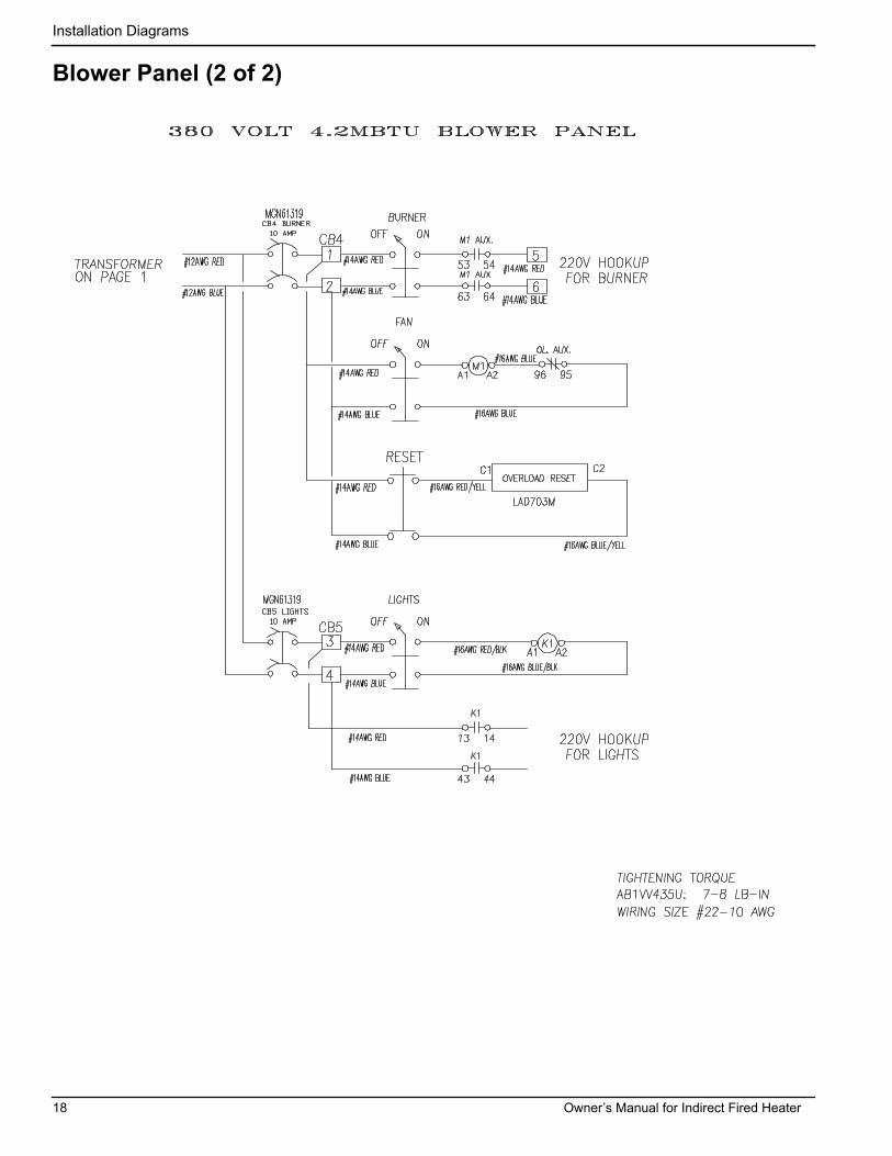
Blower Panel (2 of 2)
18 Owner’s Manual for Indirect Fired Heater

Installation Diagrams
Wiring Diagram
Owner’s Manual for Indirect Fired Heater 19

Installation Diagrams
This page intentionally left blank.
20 Owner’s Manual for Indirect Fired Heater

Owner’s Manual for Indirect Fired Heater 21
Installation Diagrams
This page intentionally left blank.

22 Owner’s Manual for Indirect Fired Heater
Installation Diagrams
This page intentionally left blank.


Part No. 10000012115 Rev. A 05/05/17©2017 Generac Mobile ProductsAll rights reserved.Specifications are subject to change without notice.No reproduction allowed in any form without prior written consent from Generac Mobile Products.
Generac Mobile Products215 Power Drive, Berlin, WI 54923
GeneracMobileProducts.com │800-926-9768 │920-361-4442