MIG-28A* - esabna.com equipment/wire feeders/mig 28a_wire... · The SEC-7A Control contains a solid...
12
INSTRUCTIONS for MIG-28A* WIRE FEEDER These INSTRUCTIONS are for experienced operators. If you are not fully familiar with the principles of operation and safe practices for arc welding equipment we urge you to read our booklet Precautions and Safe Practices for Arc Welding, Cutting and Gouging, Form 52-529. Do NOT permit untrained persons to install, operate or maintain this equipment. Do NOT attempt to install or operate this equipment until you have read and fully understand these instructions. If you do not fully understand these instructions contact your supplier for further information. Be sure to read the Safety Precautions on page 2 before installing or operating this equipment. Be sure this information reaches the operator. You can get extra copies through your supplier. SPECIFICATIONS Torch Capacity (100% duty) .................................. 250 amps DC Torch Weight, approx ..... 3 Ibs. 1.4 kg, (less wire; service lines) Control Weight, approx ........................................ 16 lbs. (7.2 kg) Primary Power Required ..................... 115 volts, 50/60 Hz, 1 ph. Wire Feed Speed Range .................. 79-709 ipm (33-300 mm/s) Wires Accommodated ....................... 030- through .045-in. hard .030- through 1/16-in. soft Dimensions, in. Torch Control Length ........... 15 (381 mm) Length. .............. 14.7 (373 mm) Width ........... 3-1/4 (82 mm) Width ................. 10.7 (272 mm) Height ............. .8 (203 mm) Height ................ 10.2 (260 mm) Handle Dia ....... .1-3/4 mm) F-12-728-C February, 1995 I. INTRODUCTION The MIG-28A Wire Feeder can be used for either short arc or spray arc welding with a constant potential (CP) or a constant current (CC) power supply. A flip of a selector switch readies the control for use with either type of welding power. The control operates from a 115 volt AC 50/60 Hz power source. The MlG-28A consists of two basic units: an SEC-7A Control and an ST-23 Torch. This instruction booklet covers the installation and operation of the complete MIG-28A (torch and control). For installation of torch accessories and torch maintenance, refer to Form 14- 353, ‘Instructions for ST-23A Mig Welding Torch’.** A. DESCRIPTION The SEC-7A Control contains a solid state governor to maintain wire feed rate for constant potential welding, and to regulate arc voltage for constant current welding. Most of the control circuits in the SEC-7A are incorpo- rated on one printed circuit board which is mounted inside the control for easy access and removal. The control circuitry contains a dynamic brake which quickly stops wire feed, to eliminate freezing of wire in the weld puddle for the vast majority of conditions. In addi- tion, an optional Anti-Stick Kit is also available for the SEC-7A to adjust the amount of wire burnback after wire feed stops, to further prevent any freezing of welding wire in the weld puddle. The ST-23 Torch is an air cooled, spool-on-gun type manual mig welding torch with a maximum current ca- pacity of 250 amperes DC continuous duty. The torch contains a complete gearmotor in the handle which pulls the welding wire from a 4-in. diameter spool, mounted in a molded case on the rear of the torch, and delivers it to the torch nozzle. The case is molded from a rugged, flame retardant, glass-reinforced polyester compound. II. SETTING UP THE MIG-28A A. EQUIPMENT SUPPLIED The MIG-28A (Series A) is available in a welding outfit under P/N 19163. Contents of the outfit are listed in Table 1. F-12-728-C
Transcript of MIG-28A* - esabna.com equipment/wire feeders/mig 28a_wire... · The SEC-7A Control contains a solid...

INSTRUCTIONS for
MIG-28A*
WIRE FEEDER
These INSTRUCTIONS are for experienced operators. If youare not fully familiar with the principles of operation and safepractices for arc welding equipment we urge you to read ourbooklet Precautions and Safe Practices for Arc Welding,Cutting and Gouging, Form 52-529. Do NOT permit untrainedpersons to install, operate or maintain this equipment. Do NOTattempt to install or operate this equipment until you have readand fully understand these instructions. If you do not fullyunderstand these instructions contact your supplier for furtherinformation. Be sure to read the Safety Precautions on page 2before installing or operating this equipment.
Be sure this information reaches the operator.You can get extra copies through your supplier.
SPECIFICATIONS
Torch Capacity (100% duty) .................................. 250 amps DCTorch Weight, approx ..... 3 Ibs. 1.4 kg, (less wire; service lines)Control Weight, approx ........................................ 16 lbs. (7.2 kg)Primary Power Required ..................... 115 volts, 50/60 Hz, 1 ph.Wire Feed Speed Range .................. 79-709 ipm (33-300 mm/s)Wires Accommodated ....................... 030- through .045-in. hard
.030- through 1/16-in. soft
Dimensions, in.Torch ControlLength ........... 15 (381 mm) Length. .............. 14.7 (373 mm)Width ........... 3-1/4 (82 mm) Width ................. 10.7 (272 mm)Height ............. .8 (203 mm) Height ................ 10.2 (260 mm)Handle Dia ....... .1-3/4 mm)
F-12-728-CFebruary, 1995
I. INTRODUCTION
The MIG-28A Wire Feeder can be used for either shortarc or spray arc welding with a constant potential (CP) ora constant current (CC) power supply. A flip of a selectorswitch readies the control for use with either type ofwelding power. The control operates from a 115 volt AC50/60 Hz power source.
The MlG-28A consists of two basic units: an SEC-7AControl and an ST-23 Torch. This instruction bookletcovers the installation and operation of the completeMIG-28A (torch and control). For installation of torchaccessories and torch maintenance, refer to Form 14-353, ‘Instructions for ST-23A Mig Welding Torch’.**
A. DESCRIPTIONThe SEC-7A Control contains a solid state governor tomaintain wire feed rate for constant potential welding,and to regulate arc voltage for constant current welding.Most of the control circuits in the SEC-7A are incorpo-rated on one printed circuit board which is mountedinside the control for easy access and removal.
The control circuitry contains a dynamic brake whichquickly stops wire feed, to eliminate freezing of wire in theweld puddle for the vast majority of conditions. In addi-tion, an optional Anti-Stick Kit is also available for theSEC-7A to adjust the amount of wire burnback after wirefeed stops, to further prevent any freezing of welding wirein the weld puddle.
The ST-23 Torch is an air cooled, spool-on-gun typemanual mig welding torch with a maximum current ca-pacity of 250 amperes DC continuous duty. The torchcontains a complete gearmotor in the handle which pullsthe welding wire from a 4-in. diameter spool, mounted ina molded case on the rear of the torch, and delivers it tothe torch nozzle. The case is molded from a rugged,flame retardant, glass-reinforced polyester compound.
II. SETTING UP THE MIG-28A
A. EQUIPMENT SUPPLIEDThe MIG-28A (Series A) is available in a welding outfitunder P/N 19163. Contents of the outfit are listed in Table1.
F-1
2-72
8-C


3
Table 1 - Contents of MIG-28A Outfit, P/N 19163
Description Qty. Part No.
SEC-7A Control 1 2075159ST-23A Torch/30-ft. service lines 1 19164Control Cable, 6-ft., 6-cond., 19 pin 1 36618Gas Hose, 12-1/2-ft. 1 40V77Contact Tip (.030" Hard & Soft) 3 996994Contact Tip (.035" Hard & Soft) 3 996995Contact Tip (3/64" Soft & .045" Hard) 3 996999Contact Tip (1/16" Soft) 3 996997Feed Roll (.030" & .035" Hard & Soft) 1 636343Torch Liner (.030 & .035 Wire) 1 19166No. 8 Nozzle Std. Duty 3 999471No. 10 Nozzle Std. Duty 2 999472
B. REQUIRED COMPANION EQUIPMENT ANDACCESSORIES
1. R-5007 Argon Regulator-Flowmeter, P/N 998124.2. 2/0 Welding Cable (customer supplied) in suitable
lengths to connect the power supply to the control andworkpiece. Terminal lug with fiber cover, P/N 81F64,is available for connecting the cable to the powersupply.
3. Gas Hose Coupling, P/N 11N17 permits you to extendgas hose by ordering additional hose (40V77).
4. One of the following types of power supplies: a. A D.C. Rectifier-Type Constant Potential Power
Supply (such as VI-206, VI-300, VI-450, etc.) asshown in Figure 2.
b. A D.C. Generator or D.C. Rectifier-Type ConstantCurrent Power Supply which does not have a built-
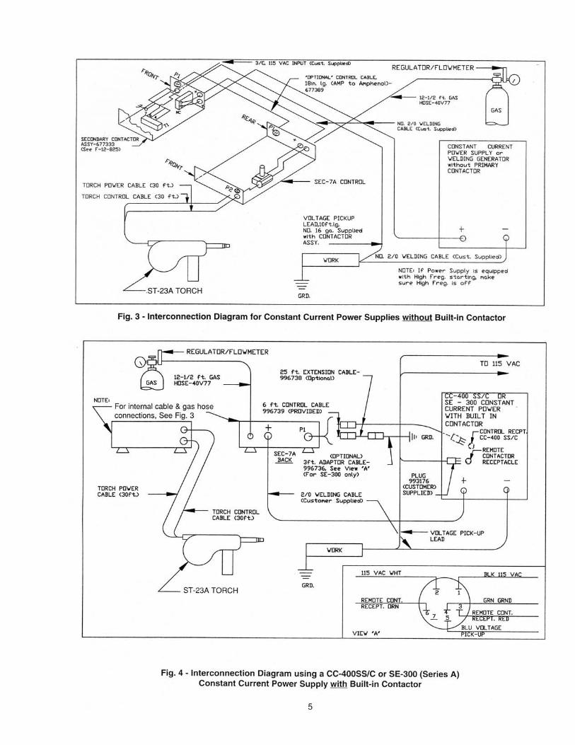
in contactor. For this type unit, a 300 Amp. Second-ary Contactor Assembly (P/N 677333) will be re-quired to interrupt the welding current between theSEC-7A Control and the power source as shown inFigure 3. (Refer to Form 12-825 for completeinstallation instructions.)
c. A D.C. Rectifier-Type Constant Current PowerSupply that contains a built-in contactor with a115-volt coil. This type unit can be operated di-rectly from the SEC-7 control as shown in Figure 4.
d. A Heliarc 306/Heliarc 350 AC/DC Power Supply mayalso be used; however, in this case an Adaptor Kit(P/N 995313) will be required. (Refer to Form 12-324 for complete installation instructions.)
5. Standard Welders Helmet with proper shade ofglass. A No. 12 glass should be used for currentsof 75 to 200 amperes.
C. OPTIONAL ACCESSORIES1. Torch Control Cable Extension Assy., (30-ft.) P/N
636968. Used to extend the length of the torch cables(see Fig. 5)
2. Torch Power and Gas Extension Adaptor, P/N 993457.This adaptor is used in conjunction with extension636968 above. Both parts enable you to extend thetorch service lines up to 60-ft. (See Fig. 5.)
3. Control Adaptor Cable (3-ft., 6-cond.) P/N 996736.Required to connect the control to any power supplywhich does not contain a remote contactor recep-tacle.
4. Control Extension Cable (25-ft.) P/N 996738. Used toextend the control to power supply cable (see Fig. 2).
Fig. 1 - Interior View of SEC-7A Control
WELD POWERSELECTOR SWITCH
SWITCH ON P/C BOARD
CONSTANTPOTENTIAL
CONSTANTCURRENT
PRINTED CIRCUIT BOARD
P.C. Board location ofSLOW INCH DOWN TRIMPOT(See Section IV-D-2.)
TRANSFORMER
POWER CABLE / GAS CONNECTIONS
WIRE INCH RELAY
TORCH SWITCH RELAY

4
5. Anti-Stick Kit, P/N 2075076. Kit permits precise ad-justment of amount of burnback after wire feed stops,to eliminate freezing of wire in weld puddle. Forinstallation refer to Section III-B
III. INSTALLATION
A. HOSE AND ELECTRICAL CONNECTIONS
CAUTION: Be sure the Main Line Switch (MLS) on thecontrol cabinet and the power supply are OFFbefore making any connections.
Depending on the type of power supply used, make thenecessary cable and hose connections in accordancewith one of the following interconnection diagrams.
Fig. 2 - Interconnection Diagram for Constant PotentialWelding
Fig. 3 - Interconnection Diagram for Constant CurrentPower Supplies without Built-in Contactor.
Fig. 4 - Interconnection Diagram when using a Con-stant Current Power Supply/Built-in Contactor.
REGULATOR/FLOWMETER
GAS
P2
SEC-7AFRONT
TORCH POWERCABLE (30 ft.)
TORCH CONTROLCABLE (30 ft.)
CONSTANT POTENTIALPOWER SUPPLY(Customer Supplied)
GRD.
WORK
2/0 WELDING CABLE(Customer Supplied)
SEC-7ABACK
P1
ST-23A TORCH
25 ft. EXTENSIONSCABLE - 996738Optional
6 ft. CONTROL CABLE-996739 (Provided)
Fig. 2 - Interconnection Diagram for Constant Potential Welding
NOTE:For Internal power cable & gas hoseconnections, See Fig. 3
B. ANTI-STICK KIT
All components of the Anti-Stick Kit are mounted on a PCboard connected to the anti-stick potentiometer. Toinstall the kit simply insert potentiometer through knock-out on back panel. Then with hardware provided tightenpotentiometer, and install knob. For electrical connec-tions refer to Figure 10.
IV. ADJUSTMENTS AND OPERATION
A. SHIELDING GAS FLOW
The torch trigger switch controls the flow of shielding gasset by the flowmeter. To check the flow, first deenergizethe control by placing the Main Line Switch (MLS) in theOFF position. Then depress the torch switch. Aftermaking the necessary adjustments to the flowmeter,place the Main Line Switch in the ON position.
B. TORCH CONTROLS
Wire feed power is provided by the permanent-magnettype DC motor in the ST-23A torch. Wire may be inchedby pressing the button on the bottom of the torch handle
CAUTION: Do not allow metal-to-metal contact between the wire feeder (control) cabinet and a metal surfaceconnected in any way to a welding ground. Without insulation, a poor work lead connection may create adifference in potential that sends part of the welding current through the safety ground wiring in the controlcable and wire feeder, resulting in burnout of that wiring and/or damage to wire feeder circuitry. If safetyground burns out, the operator may be exposed to 115 V. shock hazard.
12-1/2 ft. GASHOSE-40V77

6
2/0 WELDING CABLE(Customer Supplied)
12-1/2 ft. GASHOSE-40V77
SEC-7AFRONT
TORCH POWERCABLE (30 ft.)
POWER CABLEADAPTOR - 993457
Fig. 5 - Extending Torch Service Lines
Wire feed speed during the welding cycle is controlled bythe potentiometer on the torch.
In constant potential welding, the wire begins to feedthe instant the torch trigger is fully depressed. This isdesirable when welding with CP or CP slope controlpower. During CP operation, the potentiometer on thetorch regulate the welding current by means of the wirefeed speed. Turning the potentiometer in a clockwisedirection will increase the welding current (increase wirefeed speed); turning counterclockwise will decreasewelding current (decrease wire feed speed). An initialsetting should be low to reduce the possibility of burningthrough the plate.
In constant current welding, full torch switch depres-sion immediately initiates a slow inch down sequenceuntil the wire touches the work and stops. After the arc isestablished, normal welding speed is regulated from thetorch potentiometer. During constant current welding,the torch potentiometer controls the arc voltage. Turningthe potentiometer clockwise will decrease the arc volt-age by increasing the wire feed speed; turning it counter-clockwise will increase the arc voltage by decreasing thewire feed speed. Thus, wire feed speed is regulated thesame way in CC as in CP welding. An initial settingshould be high to avoid burnbacks.
C. CONTROL SWITCH SETTINGS (see Figs. 6- 8)1. Place the Weld Power Selector Switch inside the
control (on the PC board) to the proper position withrespect to the type of power supply being used. Referto Figure 8 for correct position of the switch.
2. Place the Main Line Switch in the ON position.3. If the optional Anti-Stick Kit has been installed, set the
potentiometer to the desired setting depending on theamount of burnback desired. The higher the setting,the greater the amount of time that the contactor isheld in to allow the wire to burn back out of the weldpuddle.
IMPORTANT: If the power supply you are using isequipped for high frequency starting,make sure that the HF. Control is in the‘OFF ’position.
D. WELDING OPERATION
With the control Main Line Switch in the ON position andthe torch, shielding gas, and power supply properlyadjusted, welding action will begin as follows:
1. In CP Welding, partial depression of the torch switchopens the gas flow valve in the torch (for preflow) andfull depression energizes the welding contactor andinitiates wire feed at welding speed to strike an arc.
REGULATOR/FLOWMETER
ST-23A TORCH
30 ft. EXTENSIONCABLE- 636968
TORCH CONTROLCABLE (30 ft.)

7
Welding will continue as long as the arc is maintainedand the torch switch is fully depressed.
2. In CC Welding, partial depressing of the torch switchopens the gas flow valve in the torch to provideshielding gas preflow. Full torch switch depressionenergizes the contactor and initiates an automaticslow inch down wire sequence. This sequence imme-diately feeds electrically hot wire at a slow inch speedand stops when the wire touches the work. After thearc is established, normal welding speed is regulatedfrom the torch potentiometer. Welding will continue aslong as the arc is maintained and the torch switch isfully depressed. The touch starting feature providedby the “slow-inch” sequence allows the operator tohold his torch position and eliminates the out-of-position problems caused by scratch starting with anextended wire.
NOTE: The slow inch control in CC welding is providedby an adjustable trimpot that has been added inthe upper right-hand portion of all PC boards(997245) manufactured after September, 1980.The wire inch speed can be varied by readjust-ing the trim pot; however, if you still prefer theoriginal scratch-starting mode of operation, sim-ply set the trim pot to its minimum setting.
To stop the welding action in CC or CP welding, slowly(for postflow) release the trigger switch until the arc isextinguished. Partially depressing the trigger switch al-lows shielding gas to continue to flow. Flow will stop whenswitch is fully released.
V. OPERATING SEQUENCE
Normal1. Partially close torch switch
—Gas valve opens (for preflow).2a. Fully close torch switch (Constant Potential Weld-
ing)—Gas valve remains open, torch switch relay ener-gizes, weld contactor closes, wire feed motor runs.
2b Fully close torch switch (constant current weld-ing)—Gas valve remains open, torch switch relay ener-gizes, weld contactor closes, and wire feed motorruns at slow inch down speed until wire toucheswork. After the arc is established, motor runs atnormal welding speed.
3. Partially release torch switch—Torch switch relay opens, weld contactor opens,wire feed motor deenergizes, brake circuit activates,gas valve remains open (for postflow).
4. Fully release torch switch—Gas valve closes.
With Optional Anti-Stick Kit InstalledSame as normal except when the torch switch is re-
leased the weld contactor is held in for a short period oftime to allow the wire to burnback out of the weld puddle.The duration of this time is controlled by the anti-stickpotentiometer.
VI. TROUBLESHOOTING
If this equipment does not operate properly, stopwork immediately and investigate the cause of themalfunction. Maintenance work must be performedby an experienced person, and electrical work by atrained electrician. Do not permit untrained personsto inspect, clean, or repair this equipment. Use onlyrecommended replacement parts.
Listed below are a number of trouble symptoms, eachfollowed by the checks or action suggested to determinethe cause. Listing of checks and/or actions is in “mostprobable” order, but is not necessarily 100% exhaustive.Always follow this general rule: Do not replace a printedcircuit (PC) board until you have made all the followingchecks. Make sure that the PC board is in good contactwith its receptacle when making the following checks.Always put the main power switch in “OFF” positionbefore removing or installing a PC board. Take great carenot to grasp or pull on components when removing a PCboard.
A. SYMPTOM: No arc.1. Welding cable circuit may be broken.2. Welding work lead connection may be poor.3 Contactor does not come in when torch switch is
closed (see B below).4. Check main power fuses and power supply.
B. SYMPTOM: Contactor does not energize whentorch switch is closed.1. Control cable may be faulty.2. Contactor coil may be open.3. Torch switch relay (TSR) may be bad; replace if
necessary (see C below).C. SYMPTOM: Torch Switch Relay (TSR) does not
energize when torch switch is closed.1. Main Line Switch on control in ‘OFF’ position.2. Fuse F1 in control may be blown.3. Torch cable or cable connections may be faulty.4. Torch Switch Relay coil may be open; check
resistance of coil; should be from 250 to 300 ohms.5. Torch switch may be faulty.
D. SYMPTOM: No wire inch.1. Main Line Switch on control in ‘OFF’ position.2. Fuse F1 in control may be blown.3. Torch cable or cable connections may be faulty.4. Wire Inch Relay (WIR) coil may be open; check
resistance of coil; should be from 250 to 300 ohms.E. SYMPTOM: Welding with CP power, wire feed
motor does not run when torch switch closed.1. Make sure Weld Power Selector Switch (WPSS) is
in "CP" position.

8
4. Motor armature may be shorted to feed roll. Replacemotor.
5. Replace PC board.
G. SYMPTOM: Wire sticks in puddle.
1. Motor brake defective; check contacts 3 and 7 onTorch Switch Relay.
2. The Optional Anti-Stick Kit may be necessary.
VII. MAINTENANCE
A. GENERAL MAINTENANCE
Little maintenance is required to keep the wire feeder intop operating condition. It is important, however, thatmoving parts such as feed and pressure rolls, wire feedmotor, etc., be kept clean and free of dust or dirt.Cleaning is best accomplished by regularly blowing offthese parts with dry compressed air. This should bedone once for every eight hours of operating time, moreoften if necessary. Refer to the torch instructions bookletF-14-353 for general torch maintenance.
Fig. 6 - SEC-7A Control, P/N 2975159 (Front View)
2. Check both TSR and WIR as described in C and D.3. If TSR and WIR check out OK; check motor brushes.
Refer to torch instructions booklet F-14-353.4. Transistors Q4 and Q5 may be defective replace if
necessary.5. Resistors R17 and R18 may be burnt; replace if
necessary.6. Replace PC board.
F. SYMPTOM: Welding with CC power, wire feedmotor does not run when torch switch closed.
1. Wire should immediately begin a slow inch downsequence. If it does not, the trimpot is either in mini-mum setting or is defective — check setting or replacePC board.
2. If motor still does not run after an arc is established,refer back to the proper interconnection diagram forcorrect cable connections.
3. Check (with ohmmeter, PC board removed) for pos-sible ground in torch switch, inch switch or motor leadconnections.
VIII. REPLACEMENT PARTS
1. Replacement parts are keyed on the illustrations which follow. Order replacement parts by part number andpart name as shown on the illustrations. DO NOT ORDER BY PART NUMBER ALONE.
2. When ordering, be sure to state quantity of each part needed.3. Always state the series or serial number of the machine on which the parts are to be used. The serial number
is stamped on the unit's nameplate.4. Indicate any special shipping instructions.5. Order replacement parts from your ESAB distributor or from ESAB Welding & Cutting Products, Customer
Service Department, Florence, SC.
COVER - 2075163
* Replace Decal if it BecomesExcessively Worn or Lost.
HANDLE - 48N65
(4) FOOT - 99W32
F1, FUSE - 82W43FUSEHOLDER - 182W15
MLS, MAIN LINESWITCH - 97W64
P2, TORCH RECEPTACLE-647233
(Ref.) Opening for TorchPower/Gas Cable. Includes:SNAP BUSHING - 647345
SILKSCREEN CABINET -679593
WARNING DECAL*2091514

9
(Ref.) Knockout Plug forOptional Anti-Stick Kit -2075076
P1, POWER SUPPLYRECEPTACLE - 634772
(Ref.) Opening for GasLine Connection. Includes:SNAP BUSHING -639533
(Ref.) Opening for PowerSupply Pos (+) OutputCable. Includes:SNAP BUSHING -647345
Fig. 7 - SEC-7A Control (Rear View)
VIEW “A”
SWITCH ONP/C BOARD
Fig. 8 - SEC-7A Control (Inside View)
ANTI STICK
CONSTANTCURRENT
CONSTANTPOTENTIAL
PC BOARD ASSY. - 997245
(Ref.) WELD POWER SELECTORSWITCH (See View “A”)
TPI, TIE POINT - 94W84
(Ref.) SLOW INCH TRIMPOT.
P3, PC BOARD RECEPTACLE636608
Q4, TRANSISTOR - 2062221(Under Heatsink)
MOUNTING BRACKET - 995297
TP2, TIE POINT - 94W84
R17, RESISTOR - 17120001
C1, CAPACITOR - 993539
HEATSINK - 2075164
MOUNTING CLAMP - 993540
POWER CABLE ADAPTOR BLOCK - 674156
(Ref.) 7/8 - 14NF - 2B - LH THREADS
(+), POWER/GAS CONNECTION ADAPTOR - 2075165(Ref.) 5/8-18NF - 2BTHREADS
TB1, TERMINAL BLOCK - 91W66
TR1, TRANSFORMER - 2062227
TSR, TORCH SWITCHRELAY - 97W55
R18, RESISTOR -17120001
TP3, TIE POINT -94W84
Q5, TRANSISTOR2062221(Under Heatsink)
WIR, WIRE INCHRELAY - 97W55
TP4, TIE POINT -94W84
HEATSINK - 2075164
POWER SUPPLYCABLE
GAS
“+”WELDING CABLE

10
ELECTRICAL PARTS LIST
Symbol
Part No.
Description
C1
993539
Capacitor, 1,500 uf, 50 WVDC
F1
82W43
Fuse, 1 Amp Standard
MLS
97W64
Switch, DPST, 15A/125V, Cutler Hammer No.
7560K5
P1
634772
Receptacle, Amphenol No. MS-3102A-18-12P
P2
647233
Receptacle, Amphenol No. MS-3102A-18-8S
P3
636608
Receptacle, PC Board
Q4, 5
2062221
Transistor, International Rectifier No. 1R3772
R-17, 18
17120001
Resistor, 1/2 Watt, 1 Ohm
TB1
91W66
Terminal Block
TP1-4
94W84
Tie Point
TR1
2062227
Transformer, 115V/25V, JWL Asso. P/N 1000-25-
20
TSR, WIR
97W55
Relay, Potter & Brumfield No. PRD11DY0
LOCATED ON ST-23
TORCH
LOCATED ON ST-23
TORCH
TORCH
MOTOR
NOTE:
1.
CONNECTION FOR P/C BOARD
ANTI-STICK OPTION
PI-F
" - "
WORK
" + "
ARCVIO
P3
P2-G
P2-F
YEL
RED
BLK MLS
(1)
(2)
1 AMP
FI
TB1-5
BLK
120 VAC
SEE NOTE 1
23
REDTSRBLU
PI-C
WC
PI-D
PI-A
GRN
PI-E ORN
(1)
(2)
(3)
(4)25.2 VACRED
RED
GND STUD
PI-B WHT MLS
(3)
(4)
RED
RED
YEL
YEL
YEL
YEL
YEL
BRN
BRN
TB1-1
GRN
4
WIR
TSR - +
1500 uF
50 VDC
GRY
TBI-8
TBI-7
BLU
BRNBLU
BLU
BLU
GRY
TSR
73
P2-D
P2-E
TSR
GRY
GRY
Q5
RIB
1/2 W
IW
3 35 7GRY
1/2 W
IW
TB1-2
R17
TB1-6
TB1-3
VIO
21
GRY
WIS
P2-B
TS
SEE NOTE 1
1 RED
21
P2-A
VIO
P3
15 12
22 13
11
18 19 10
4 32
14
9
117
WIR
WIR
ORN
BLK
TB1-4
C
C1
BLK
Q4
P2-H
C
Fig
. 9 -
Sch
emat
ic D
iag
ram
, SE
C-7
A C
on
tro
l

11
POWER SUPPLY WITH
Fig
. 10
- W
irin
g D
iag
ram
, SE
C-7
A C
on
tro
l

F-12-728-C 2/95 Printed in U.S.A.


![SAW [Wire/Flux Combination] 99 - argonarcwelding.co.zaargonarcwelding.co.za/images/HYUNDAI WELDING C.,LTD... · SAW [Wire/Flux Combination] 99 GMAW [Solid Wire & Stainless MIG Wire]](https://static.fdocuments.in/doc/165x107/5ab797e07f8b9a684c8baf2b/saw-wireflux-combination-99-welding-cltdsaw-wireflux-combination-99.jpg)