WIRE FEED MIG WELDER - · PDF fileWIRE FEED MIG WELDER Model No. 196.205680 / ... Selecting...
52
Owner's Manual I (RRFTSMRN1 WIRE FEED MIG WELDER Model No. 196.205680 / CAUTION: Before using this product, read this manual and follow all its Safety Rules and Operating Instructions. EspaSol p.27 Sears, Roebuck and Co., Hoffman Estates, IL 60179 U.S.A. www.sears.com/craftsman
Transcript of WIRE FEED MIG WELDER - · PDF fileWIRE FEED MIG WELDER Model No. 196.205680 / ... Selecting...
Owner's Manual
I (RRFTSMRN1
WIRE FEED MIG WELDER
Model No.196.205680
/
CAUTION: Before using thisproduct, read this manual andfollow all its Safety Rules andOperating Instructions.
EspaSol p.27
Sears, Roebuck and Co., Hoffman Estates, IL 60179 U.S.A.www.sears.com/craftsman
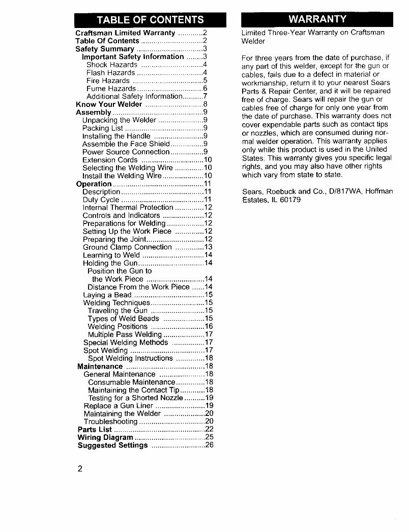
Craftsman Limited Warranty ............ 2Table Of Contents .............................. 2Safety Summary ................................ 3
Important Safety Information ........ 3Shock Hazards .............................. 4Flash Hazards ................................ 4Fire Hazards .................................. 5Fume Hazards ................................ 6Additional Safety Information .......... 7
Know Your Welder ............................ 8Assembly ............................................ 9
Unpacking the Welder ...................... 9Packing List ...................................... 9Installing the Handle ........................ 9Assemble the Face Shield ................ 9Power Source Connection ................ 9Extension Cords .............................. 10
Selecting the Welding Wire .............. 10Install the Welding Wire .................... 10
Operation ............................................ 11Description ........................................ 11Duty Cycle ........................................ 11Internal Thermal Protection .............. 12Controls and Indicators .................... 12Preparations for Welding .................. 12Setting Up the Work Piece .............. 12Preparing the Joint ............................ 12Ground Clamp Connection .............. 13Learning to Weld .............................. 14Holding the Gun ................................ 14
Position the Gun tothe Work Piece ............................ 14
Distance From the Work Piece ...... 14
Laying a Bead .................................. 15Welding Techniques .......................... 15
Traveling the Gun .......................... 15Types of Weld Beads .................... 15Welding Positions .......................... 16Multiple Pass Welding .................... 17
Special Welding Methods ................ 17Spot Welding .................................... 17
Spot Welding Instructions .............. 18Maintenance ...................................... 18
General Maintenance ...................... 18Consumable Maintenance .............. 18Maintaining the Contact Tip ............ 18Testing for a Shorted Nozzle .......... 19
Replace a Gun Liner ........................ 19Maintaining the Welder .................... 20Troubleshooting ................................ 20
Parts List ............................................ 22Wiring Diagram .................................. 25Suggested Settings .......................... 26
2
Limited Three-Year Warranty on CraftsmanWelder
For three years from the date of purchase, ifany part of this welder, except for the gun orcables, fails due to a defect in material orworkmanship, return it to your nearest SearsParts & Repair Center, and it will be repairedfree of charge. Sears will repair the gun orcables free of charge for only one year fromthe date of purchase. This warranty does notcover expendable parts such as contact tipsor nozzles, which are consumed during nor-mal welder operation. This warranty appliesonly while this product is used in the UnitedStates. This warranty gives you specific legalrights, and you may also have other rightswhich vary from state to state.
Sears, Roebuck and Co., D/817WA, HoffmanEstates, IL 60179
Everycraftsmanrespectsthe toolswithwhichtheywork.They knowthat the toolsrepresent years of constantly improveddesigns and developments. The true crafts-man also knows that tools are dangerous ifmisused or abused.
Reading this operator's manual before usingthe welder will enable you to do a better,
safer job. Learn the welder's applicationsand limitations as well as the specific poten-tial hazards peculiar to welding.
IMPORTANT SAFETYINFORMATION
The following safety information is providedas guidelines to help you operate your newwelder under the safest possible conditions.Any equipment that uses electrical powercan be potentially dangerous to use whensafety or safe handling instructions are notknown or not followed. The following safetyinformation is provided to give the user theinformation necessary for safe use andoperation.
A procedure step preceded by aWARNING is an indication that the next stepcontains a procedure that might be injuriousto a person if proper safety precautions arenot heeded.
A procedure preceded by a CAUTION is anindication that the next step contains aprocedure that might damage the equipmentbeing used.
A NOTE may be used before or after a pro-cedure step to highlight or explain somethingin that step.
READ ALL SAFETY INSTRUCTIONSCAREFULLY before attempting to install,operate, or service this welder. Failure tocomply with these instructions couldresult in personal injury and/or property dam-
age.
RETAIN THESE INSTRUCTIONS FORFUTURE REFERENCE.
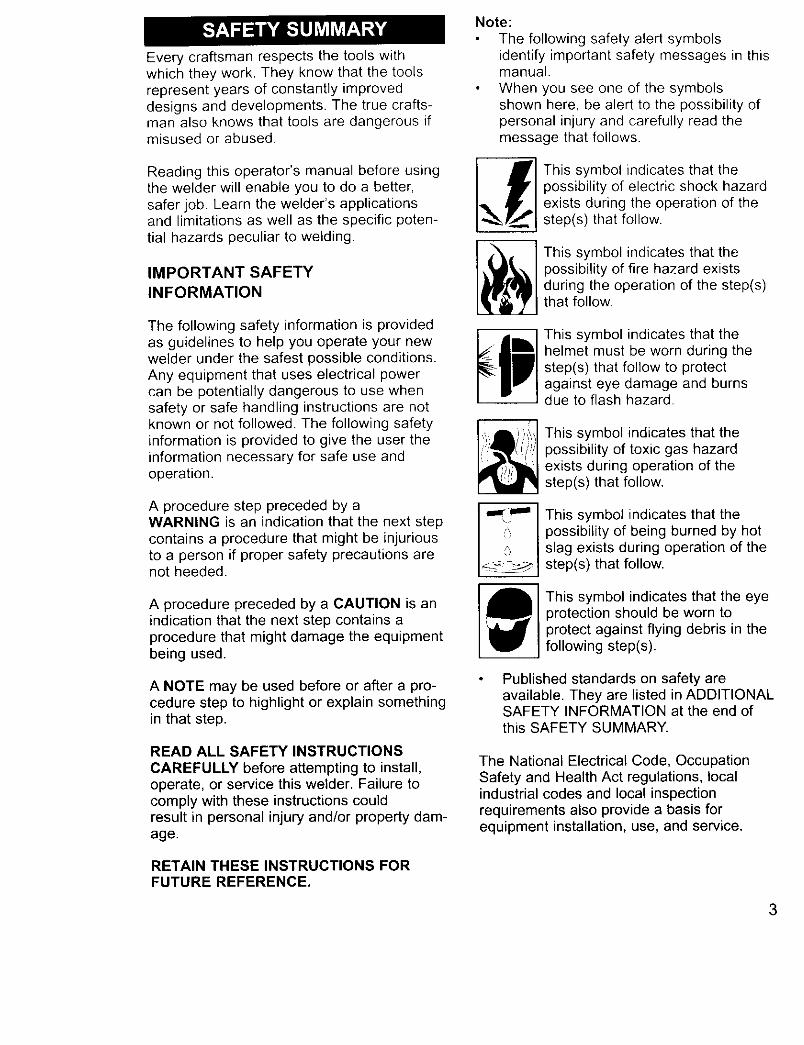
Note:
The following safety alert symbolsidentify important safety messages in thismanual.
When you see one of the symbolsshown here, be alert to the possibility ofpersonal injury and carefully read themessage that follows.
_'] This symbol indicates that the
I possibility of electric shock hazard,,_ Ii' I exists during the operation of the
•_J step(s) that follow.
This symbol indicates that thepossibility of fire hazard existsduring the operation of the step(s)that follow.
This symbol indicates that thehelmet must be worn during thestep(s) that follow to protectagainst eye damage and burnsdue to flash hazard.
This symbol indicates that thepossibility of toxic gas hazardexists during operation of thestep(s) that follow.
This symbol indicates that thepossibility of being burned by hotslag exists during operation of thestep(s) that follow.
This symbol indicates that the eyeprotection should be worn toprotect against flying debris in thefollowing step(s).
Published standards on safety areavailable. They are listed in ADDITIONALSAFETY INFORMATION at the end ofthis SAFETY SUMMARY.
The National Electrical Code, OccupationSafety and Health Act regulations, localindustrial codes and local inspectionrequirements also provide a basis forequipment installation, use, and service.
3
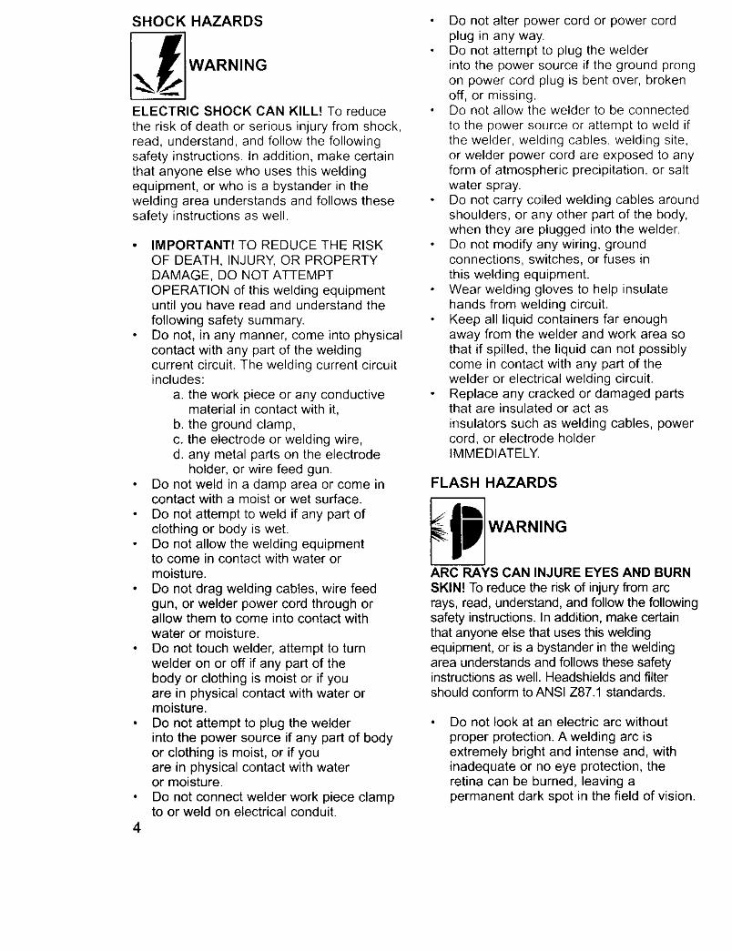
SHOCK HAZARDS
I.__ ]WARN' OELECTRIC SHOCK CAN KILL! To reduce
the risk of death or serious injury from shock,read, understand, and follow the followingsafety instructions. In addition, make certainthat anyone else who uses this weldingequipment, or who is a bystander in thewelding area understands and follows thesesafety instructions as well.
4
IMPORTANT! TO REDUCE THE RISKOF DEATH, INJURY, OR PROPERTYDAMAGE, DO NOT ATTEMPTOPERATION of this welding equipmentuntil you have read and understand thefollowing safety summary.Do not, in any manner, come into physicalcontact with any part of the weldingcurrent circuit. The welding current circuitincludes:
a. the work piece or any conductivematerial in contact with it,
b. the ground clamp,c. the electrode or welding wire,d. any metal parts on the electrode
holder, or wire feed gun.Do not weld in a damp area or come incontact with a moist or wet surface.
Do not attempt to weld if any part ofclothing or body is wet.Do not allow the welding equipmentto come in contact with water ormoisture.Do not drag welding cables, wire feedgun, or welder power cord through orallow them to come into contact withwater or moisture.
Do not touch welder, attempt to turnwelder on or off if any part of thebody or clothing is moist or if youare in physical contact with water ormoisture.
Do not attempt to plug the welderinto the power source if any part of bodyor clothing is moist, or if youare in physical contact with wateror moisture.
Do not connect welder work piece clampto or weld on electrical conduit.
Do not alter power cord or power cordplug in any way.Do not attempt to plug the welderinto the power source if the ground prongon power cord plug is bent over, brokenoff, or missing.Do not allow the welder to be connected
to the power source or attempt to weld ifthe welder, welding cables, welding site,or welder power cord are exposed to anyform of atmospheric precipitation, or saltwater spray.Do not carry coiled welding cables aroundshoulders, or any other part of the body,when they are plugged into the welder.Do not modify any wiring, groundconnections, switches, or fuses inthis welding equipment.Wear welding gloves to help insulatehands from welding circuit.Keep all liquid containers far enoughaway from the welder and work area sothat if spilled, the liquid can not possiblycome in contact with any part of thewelder or electrical welding circuit.Replace any cracked or damaged partsthat are insulated or act asinsulators such as welding cables, powercord, or electrode holderIMMEDIATELY.
FLASH HAZARDS
_p] WARNING
ARC RAYS CAN INJURE EYES AND BURN
SKIN! To reduce the risk of injury from arcrays, read, understand, and follow the followingsafety instructions. In addition, make certainthat anyone else that uses this weldingequipment, or is a bystander in the weldingarea understands and follows these safetyinstructions as well. Headshields and filtershould conform to ANSI Z87.1 standards.
Do not look at an electric arc without
proper protection. A welding arc isextremely bright and intense and, withinadequate or no eye protection, theretina can be burned, leaving apermanent dark spot in the field of vision.
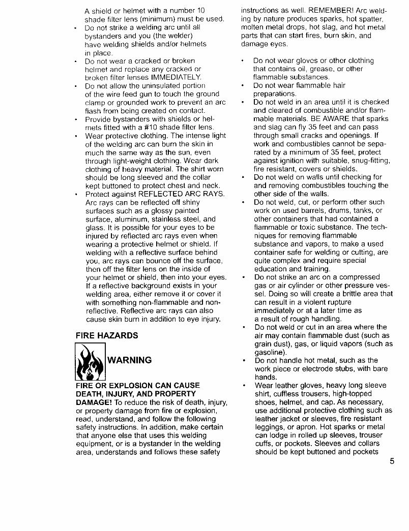
A shieldor helmetwitha number10shadefilter lens (minimum)mustbe used.Donot strikea weldingarc untilallbystandersand you (the welder)haveweldingshieldsand/orhelmetsin place.Donot wear a crackedor brokenhelmetand replaceanycrackedorbrokenfilter lensesIMMEDIATELY.Do notallow the uninsulatedportionof the wire feedgun to touchthe groundclampor groundedwork to preventan arcflash from beingcreatedon contact.Providebystanderswithshieldsor hel-metsfitted witha #10 shadefilter lens.Wearprotectiveclothing.The intenselightof the weldingarc canburnthe skin inmuchthe samewayas the sun, eventhroughlight-weightclothing.Weardarkclothingof heavymaterial.The shirtwornshouldbe long sleevedand the collarkeptbuttonedto protectchestand neck.ProtectagainstREFLECTEDARCRAYS.Arc rayscan be reflectedoff shinysurfacessuchas a glossy paintedsurface,aluminum,stainlesssteel,andglass. It is possiblefor youreyesto beinjuredby reflectedarc raysevenwhenwearinga protectivehelmetor shield. Ifweldingwitha reflectivesurfacebehindyou,arc rayscanbounceoff the surface,thenoff thefilter lens on the insideofyour helmetor shield,then intoyoureyes.If a reflectivebackgroundexists in yourweldingarea,eitherremoveit or cover itwithsomethingnon-flammableand non-reflective.Reflectivearcrayscan alsocauseskin burn inadditionto eye injury.
FIRE HAZARDS
WARNING
FIRE OR EXPLOSION CAN CAUSE
DEATH, INJURY, AND PROPERTYDAMAGE! To reduce the risk of death, injury,or property damage from fire or explosion,read, understand, and follow the followingsafety instructions. In addition, make certainthat anyone else that uses this weldingequipment, or is a bystander in the weldingarea, understands and follows these safety
instructions as well. REMEMBER! Arc weld-ing by nature produces sparks, hot spatter,molten metal drops, hot slag, and hot metalparts that can start fires, burn skin, anddamage eyes.
Do not wear gloves or other clothingthat contains oil, grease, or otherflammable substances.Do not wear flammable hairpreparations.Do not weld in an area until it is checkedand cleared of combustible and/or flam-
mable materials. BE AWARE that sparksand slag can fly 35 feet and can passthrough small cracks and openings. Ifwork and combustibles cannot be sepa-rated by a minimum of 35 feet, protectagainst ignition with suitable, snug-fitting,fire resistant, covers or shields.Do not weld on walls until checking forand removing combustibles touching theother side of the walls.
Do not weld, cut, or perform other suchwork on used barrels, drums, tanks, orother containers that had contained aflammable or toxic substance. The tech-
niques for removing flammablesubstance and vapors, to make a usedcontainer safe for welding or cutting, arequite complex and require specialeducation and training.Do not strike an arc on a compressedgas or air cylinder or other pressure ves-sel. Doing so will create a brittle area thatcan result in a violent ruptureimmediately or at a later time asa result of rough handling.Do not weld or cut in an area where the
air may contain flammable dust (such asgrain dust), gas, or liquid vapors (such asgasoline).Do not handle hot metal, such as thework piece or electrode stubs, with barehands.Wear leather gloves, heavy long sleeveshirt, cuffless trousers, high-toppedshoes, helmet, and cap. As necessary,use additional protective clothing such asleather jacket or sleeves, fire resistantleggings, or apron. Hot sparks or metalcan lodge in rolled up sleeves, trousercuffs, or pockets. Sleeves and collarsshould be kept buttoned and pockets
5
eliminated from the shirt front.Have fire extinguisher equipment handyfor immediate use! A portable chemicalfire extinguisher, type ABC, isrecommended.
Wear ear plugs when welding overheadto prevent spatter or slag from fallinginto ear.
Make sure welding area has a good,solid, safe floor, preferably concrete ormasonry, not tiled, carpeted, or made ofany other flammable material.Protect flammable walls, ceilings,and floors with heat resistant coversor shields.
Check welding area to make sure itis free of sparks, glowing metal or slag,and flames before leaving the weldingarea.
FUME HAZARDS
WARNING
FUMES, GASSES, AND VAPORS CANCAUSE DISCOMFORT, ILLNESS, ANDDEATH! To reduce the risk of discomfort, ill-ness, or death, read, understand, and followthe following safety instructions. In addition,make certain that anyone else that uses thiswelding equipment or is a bystander in thewelding area, understands and follows thesesafety instructions as well.
6
Do not weld in an area until it is checkedfor adequate ventilation as described inANSI standard #Z49.1. If ventilation is
not adequate to exchange all fumes andgasses generated during the weldingprocess with fresh air, do not weld unlessyou (the welder) and all bystanders arewearing air-supplied respirators.Do not heat metals coated with, or thatcontain, materials that produce toxicfumes (such as galvanized steel), unlessthe coating is removed. Make certain thearea is well ventilated, and the operatorand all bystanders are wearing air-sup-plied respirators.Do not weld, cut, or heat lead, zinc,cadmium, mercury, beryllium, or similarmetals without seeking professional
advice and inspection of the ventilation ofthe welding area. These metals produceEXTREMELY TOXIC fumes which cancause discomfort, illness, and death.Do not weld or cut in areas that are nearchlorinated solvents. Vapors from chlori-nated hydrocarbons, such astrichloroethylene and perchloroethylene,can be decomposed by the heat of anelectric arc or its ultraviolet radiation.These actions can cause PHOSGENE, aHIGHLY TOXIC gas to form, along withother lung and eye-irritating gasses. Donot weld or cut where these solventvapors can be drawn into the work areaor where the ultraviolet radiation can penetrate to areas containing even verysmall amounts of these vapors.Do not weld in a confined area unless it
is being ventilated or the operator (andanyone else in the area) is wearing anair-supplied respirator.Stop welding if you develop momentaryeye, nose, or throat irritation as this indi-cates inadequate ventilation. Stop workand take necessary steps to improveventilation in the welding area. Do notresume welding if physical discomfortpersists.
ADDITIONAL SAFETYINFORMATIONFor additional information concerningwelding safety, refer to the followingstandards and comply with them as
applicable.
ANSI Standard Z49.1 SAFETY INWELDING AND CUTTING - obtainable
from the American Welding Society, 550NW Le Jeune Road, Miami, FL 33126Telephone (800) 443-9353,Fax (305) 443-7559 - www.amweld.orgor www.aws.orgANSI Standard Z87.1 - SAFE PRAC-TICE FOR OCCUPATION AND EDUCA-TIONAL EYE AND FACE PROTECTION- obtainable from the American NationalStandards Institute, 11 West 42nd St.,New York, NY 10036Telephone (212) 642-4900,Fax (212) 398-0023 - www.ansi.orgNFPA Standard 51B - CUTTING ANDWELDING PROCESS - obtainable fromthe National Fire Protection Association,1 Batterymarch Park, P.O. Box 9101,Quincy, MA 02269-9101Telephone (617) 770-3000Fax (617) 770-0700 - www.nfpa.org
OSHA Standard 29 CFR, Part 1910,Subpart Q., WELDING, CUTTING ANDBRAZING - obtainable from your stateOSHA office or U.S. Dept. of LaborOSHA, Office of Public Affairs, RoomN3647, 200 Constitution Ave.,Washington, DC 20210 - www.osha.govCSA Standard W117.2 - Code for SAFE-TY IN WELDING AND CUTTING. -obtainable from Canadian StandardsAssociation, 178 Rexdale Blvd.,Etobicoke, Ontario M9W 1R3 -www.csa.ca
American Welding Society StandardA6.0. WELDING AND CUTTING CON-TAINERS WHICH HAVE HELD COM-BUSTIBLES. - obtainable from the
American Welding Society, 550 NW LeJeune Road, Miami, FL 33126Telephone (800) 443-9353,Fax (305) 443-7559 - www.amweld.orgor www.aws.org
7
HandleGun Cable
Wire Speed
Power"Switch
J
WeldingGun Voltage Clamp
Selector Gr( undCable
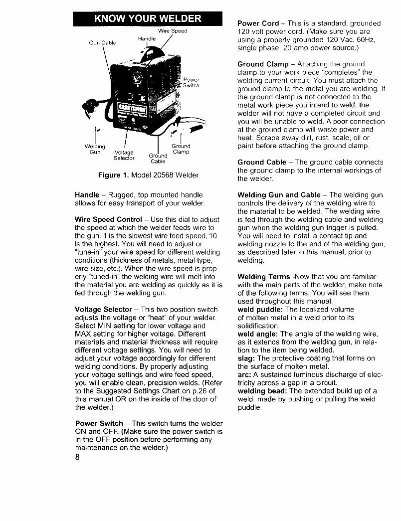
Figure 1. Model 20568 Welder
Handle - Rugged, top mounted handleallows for easy transport of your welder.
Wire Speed Control - Use this dial to adjustthe speed at which the welder feeds wire tothe gun. 1 is the slowest wire feed speed, 10is the highest. You will need to adjust or"tune-in" your wire speed for different weldingconditions (thickness of metals, metal type,wire size, etc.). When the wire speed is prop-erly "tuned-in" the welding wire will melt intothe material you are welding as quickly as it isfed through the welding gun.
Voltage Selector - This two position switchadjusts the voltage or "heat" of your welder.Select MIN setting for lower voltage andMAX setting for higher voltage. Differentmaterials and material thickness will requiredifferent voltage settings. You will need toadjust your voltage accordingly for differentwelding conditions. By properly adjustingyour voltage settings and wire feed speed,you will enable clean, precision welds. (Referto the Suggested Settings Chart on p.26 ofthis manual OR on the inside of the door ofthe welder.)
Power Switch - This switch turns the welder
ON and OFF. (Make sure the power switch isin the OFF position before performing anymaintenance on the welder.)8
Power Cord - This is a standard, grounded120 volt power cord. (Make sure you areusing a properly grounded 120 Vac, 60Hz,single phase, 20 amp power source.)
Ground Clamp - Attaching the groundclamp to your work piece "completes" thewelding current circuit. You must attach theground clamp to the metal you are welding. Ifthe ground clamp is not connected to themetal work piece you intend to weld, thewelder will not have a completed circuit andyou will be unable to weld. A poor connectionat the ground clamp will waste power andheat. Scrape away dirt, rust, scale, oil orpaint before attaching the ground clamp.
Ground Cable - The ground cable connectsthe ground clamp to the internal workings ofthe welder.
Welding Gun and Cable - The welding guncontrols the delivery of the welding wire tothe material to be welded. The welding wireis fed through the welding cable and weldinggun when the welding gun trigger is pulled.You will need to install a contact tip andwelding nozzle to the end of the welding gun,as described later in this manual, prior towelding.
Welding Terms -Now that you are familiarwith the main parts of the welder, make noteof the following terms. You will see themused throughout this manual.weld puddle: The localized volumeof molten metal in a weld prior to itssolidification.weld angle: The angle of the welding wire,as it extends from the welding gun, in rela-tion to the item being welded.slag: The protective coating that forms onthe surface of molten metal.
arc: A sustained luminous discharge of elec-tricity across a gap in a circuit.welding bead: The extended build up of aweld, made by pushing or pulling the weldpuddle.
Thefollowingproceduresdescribetheprocessrequiredto assemble,install,maintain,and pre-pareto weldwithyournewwirefeedacwelder.UNPACKING THE WELDER1. Removeanycartonsor bagscontaining
parts/accessories.(Mostpartsareshippedinside thewelderdoor.)
2. Openthecartonsorbagspackedwithyourwelderandinspecttheircontentsfordamage.
3. Layoutthe partsand comparethemtothe the packinglist in Table1tofamiliarizeyourselfwith the partsandwhat theyare called.Thiswill helpyouwhenreadingthe manual.
PACKING LISTTable 1 contains a list of the items you willfind packed in the carton.
Table 1. Packing List
ITEM QTY.
Welder 1Face Shield 1Face Shield Handle 1Handle Screws 2Shaded Lens 1Welder Handle 1Wire Brush/Hammer 1
Parts Bag 1Contact Tip 0.030 5Contact Tip 0.040 5Nozzle 2
Wire .030 Fluxcore (1/2lb.)Manual, Instruction 1
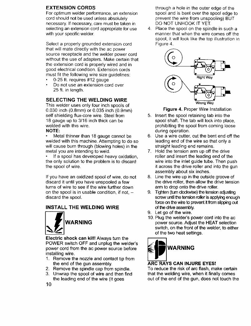
INSTALLING THE HANDLE1. Insert the tabs of the welder handle into
the slots provided on the top of the welder.2. Insert a large flat head screw (included in
the accessories bag) into each hole onthe top of the welder handle.
3. With a flat tip screwdriver, securelytighten both screws. (see Figure 2)
I 1
! !Figure 2. Handle Installation
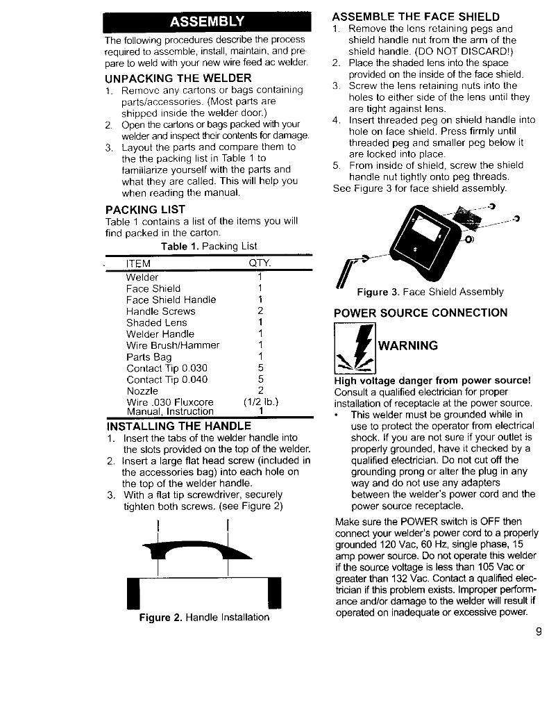
ASSEMBLE THE FACE SHIELD
1. Remove the lens retaining pegs andshield handle nut from the arm of theshield handle. (DO NOT DISCARD!)
2. Place the shaded lens into the spaceprovided on the inside of the face shield.
3. Screw the lens retaining nuts into theholes to either side of the lens until theyare tight against lens.
4. Insert threaded peg on shield handle intohole on face shield. Press firmly untilthreaded peg and smaller peg below itare locked into place.
5. From inside of shield, screw the shieldhandle nut tightly onto peg threads.
See Figure 3 for face shield assembly.
Figure 3. Face Shield Assembly
POWER SOURCE CONNECTION
High voltage danger from power source!Consult a qualified electrician for properinstallation of receptacle at the power source.
This welder must be grounded while inuse to protect the operator from electricalshock. If you are not sure if your outlet isproperly grounded, have it checked by aqualified electrician. Do not cut off thegrounding prong or alter the plug in anyway and do not use any adaptersbetween the welder's power cord and thepower source receptacle.
Make sure the POWER switch is OFF then
connect your welder's power cord to a properlygrounded 120 Vac, 60 Hz, single phase, 15amp power source. Do not operate this welderif the source voltage is less than 105 Vac orgreater than 132 Vac. Contact a qualified elec-trician if this problem exists. Improper perform-ance and/or damage to the welder will result ifoperated on inadequate or excessive power.
9
EXTENSION CORDS
For optimum welder performance, an extensioncord should not be used unless absolutelynecessary. If necessary, care must be taken inselecting an extension cord appropriate for usewith your specific welder.
Select a properly grounded extension cordthat will mate directly with the ac powersource receptacle and the welder power cordwithout the use of adapters. Make certain thatthe extension cord is properly wired and ingood electrical condition. Extension cordsmust fit the following wire size guidelines:
0-25 ft. requires #12 gaugeDo not use an extension cord over
25 ft. in length.
SELECTING THE WELDING WIRE
This welder uses only four inch spools of0.030 inch (0.8mm) or 0.035 inch (0.9mm)self shielding flux-core wire. Steel from18 gauge up to 3/16 inch thick can bewelded with this wire.NOTE:
Metal thinner than 18 gauge cannot bewelded with this machine. Attempting to do sowill cause burn through (blowing holes) in themetal you are intending to weld.
If a spool has developed heavy oxidation,the only solution to the problem is to discardthe spool of wire.
If you have an oxidized spool of wire, do notdiscard it until you have unspooled a fewturns of wire to see if the wire further down
on the spool is in usable condition, if not, -discard the spool.
INSTALL THE WELDING WIRE
Electric shock can kill! Always turn thePOWER switch OFF and unplug the welder'spower cord from the ac power source beforeinstalling wire.1. Remove the nozzle and contact tip from
the end of the gun assembly.2. Remove the spindle cap from spindle.3. Unwrap the spool of wire and then find
the leading end of the wire (it goes10
.
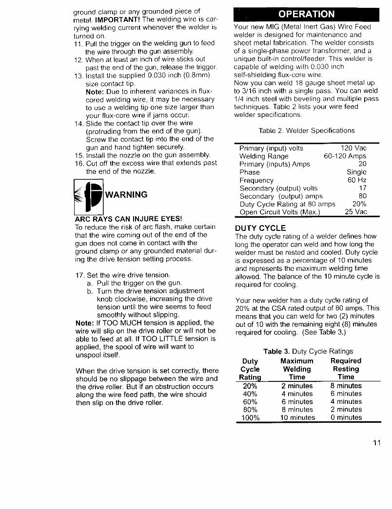
through a hole in the outer edge of thespool and is bent over the spool edge toprevent the wire from unspooling) BUTDO NOT UNHOOK IT YET.
Place the spool on the spindle in such amanner that when the wire comes off thespool, it will look like the top illustration inFigure 4.
Wrong Way
Figure 4. Proper Wire Installation
5. Insert the spool retaining tab into thespool shaft. The tab will lock into place,prohibiting the spool from coming looseduring operation.
6. Use a wire cutter, cut the bent end off theleading end of the wire so that only astraight leading end remains.
7. Hold the tension arm up off the driveroller and insert the leading end of thewire into the inlet guide tube. Then pushit across the drive roller and into the gunassembly about six inches.
8. Line the wire up in the outside groove ofthe drive roller, then allow the drive tensionarm to drop onto the drive roller.
9. Tighten (turn clockwise) the tension adjustingscrew until the tension roller is applying enoughforce on the wire to prevent it from slipping outof the drive assembly.
9. Let go of the wire.10. Plug the welder's power cord into the ac
power source. Adjust the HEAT selectionswitch, on the front of the welder, to eitherof the two heat settings.
ARC RAYS CAN INJURE EYES!To reduce the risk of arc flash, make certainthat the welding wire, when it finally comesout of the end of the gun, does not touch the
ground clamp or any grounded piece ofmetal. IMPORTANT! The welding wire is car-
rying welding current whenever the welder isturned on.11. Pull the trigger on the welding gun to feed
the wire through the gun assembly.12. When at least an inch of wire sticks out
past the end of the gun, release the trigger.13. Install the supplied 0.030 inch (0.8mm)
size contact tip.Note: Due to inherent variances in flux-cored welding wire, it may be necessaryto use a welding tip one size larger thanyour flux-core wire if jams occur.
14. Slide the contact tip over the wire(protruding from the end of the gun).Screw the contact tip into the end of the
gun and hand tighten securely.15. Install the nozzle on the gun assembly.16. Cut off the excess wire that extends past
the end of the nozzle.
ARC RAYS CAN INJURE EYES!To reduce the risk of arc flash, make certain
that the wire coming out of the end of thegun does not come in contact with theground clamp or any grounded material dur-ing the drive tension setting process.
17. Set the wire drive tension.
a. Pull the trigger on the gun.b. Turn the drive tension adjustment
knob clockwise, increasing the drivetension until the wire seems to feed
smoothly without slipping.Note: If TOO MUCH tension is applied, thewire will slip on the drive roller or will not beable to feed at all. If TOO LITTLE tension is
applied, the spool of wire will want tounspool itself.
When the drive tension is set correctly, thereshould be no slippage between the wire andthe drive roller. But if an obstruction occurs
along the wire feed path, the wire shouldthen slip on the drive roller.
Your new MIG (Metal Inert Gas) Wire Feedwelder is designed for maintenance andsheet metal fabrication. The welder consists
of a single-phase power transformer, and aunique built-in control/feeder. This welder iscapable of welding with 0.030 inchself-shielding flux-core wire.Now you can weld 18 gauge sheet metal upto 3/16 inch with a single pass. You can weld1/4 inch steel with beveling and multiple passtechniques. Table 2 lists your wire feedwelder specifications.
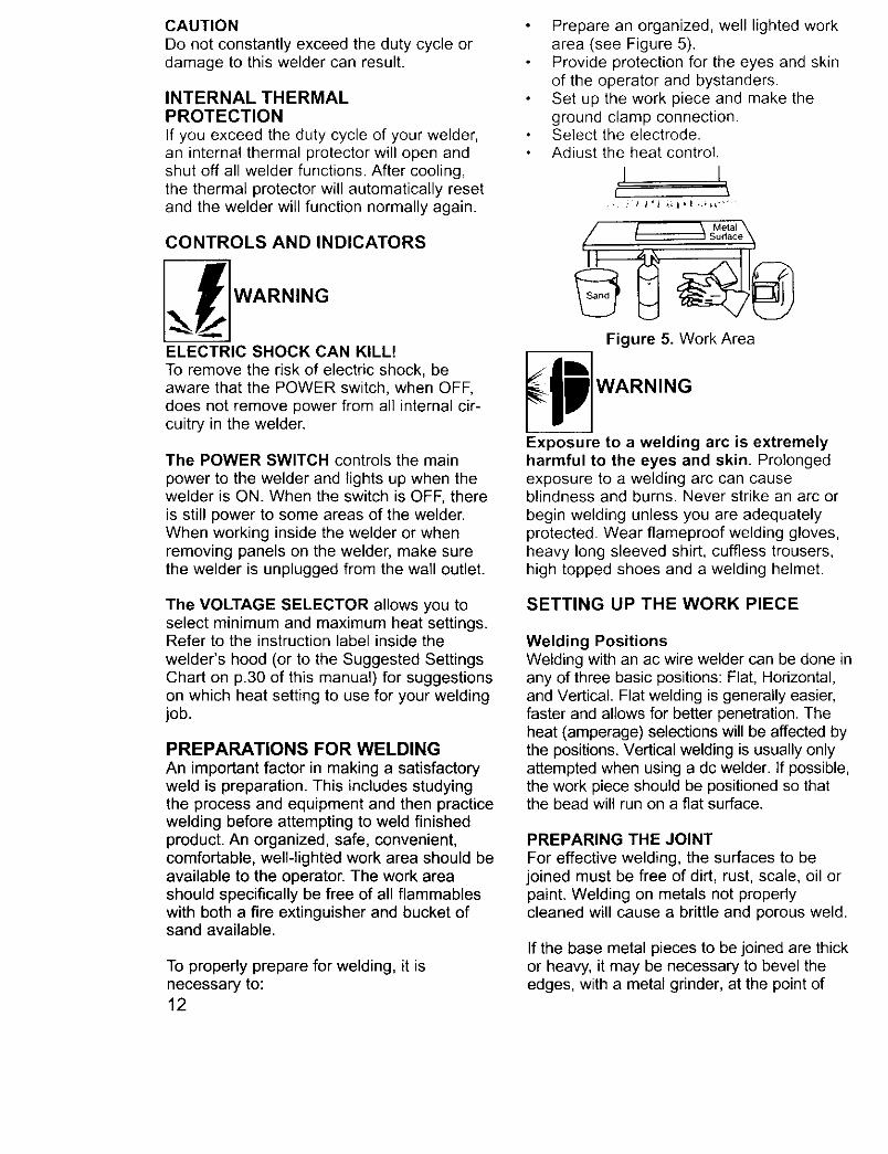
Table 2. Welder Specifications
Primary (input) volts 120 VacWelding Range 60-120 AmpsPrimary (inputs) Amps 20Phase SingleFrequency 60 HzSecondary (output) volts 17Secondary (output) amps 80Duty Cycle Rating at 80 amps 20%
Open Circuit Volts/Max.! 25 Vac
DUTY CYCLE
The duty cycle rating of a welder defines howlong the operator can weld and how long thewelder must be rested and cooled. Duty cycleis expressed as a percentage of 10 minutesand represents the maximum welding timeallowed. The balance of the 10 minute cycle isrequired for cooling.
Your new welder has a duty cycle rating of20% at the CSA rated output of 80 amps. Thismeans that you can weld for two (2) minutesout of 10 with the remaining eight (8) minutesrequired for cooling. (See Table 3.)
Table 3. Duty Cycle Ratings
Duty Maximum RequiredCycle Welding RestingRating Time Time
20% 2 minutes 8 minutes40% 4 minutes 6 minutes60% 6 minutes 4 minutes80% 8 minutes 2 minutes100% 10 minutes 0 minutes
11
CAUTIONDo not constantly exceed the duty cycle ordamage to this welder can result.
INTERNAL THERMALPROTECTIONIf you exceed the duty cycle of your welder,an internal thermal protector will open andshut off all welder functions. After cooling,the thermal protector will automatically resetand the welder will function normally again.
Prepare an organized, well lighted workarea (see Figure 5).Provide protection for the eyes and skinof the operator and bystanders.Set up the work piece and make theground clamp connection.Select the electrode.Adiust the heat control.
I I
CONTROLS AND INDICATORS
_ WARNING
ELECTRIC SHOCK CAN KILL!To remove the risk of electric shock, beaware that the POWER switch, when OFF,does not remove power from all internal cir-cuitry in the welder.
The POWER SWITCH controls the main
power to the welder and lights up when thewelder is ON. When the switch is OFF, thereis still power to some areas of the welder.When working inside the welder or whenremoving panels on the welder, make surethe welder is unplugged from the wall outlet.
Figure 5. Work Area
_1 WARNING
Exposure to a welding arc is extremelyharmful to the eyes and skin. Prolongedexposure to a welding arc can causeblindness and burns. Never strike an arc or
begin welding unless you are adequatelyprotected. Wear flameproof welding gloves,heavy long sleeved shirt, cuffless trousers,high topped shoes and a welding helmet.
The VOLTAGE SELECTOR allows you toselect minimum and maximum heat settings.Refer to the instruction label inside the
welder's hood (or to the Suggested SettingsChart on p.30 of this manual) for suggestionson which heat setting to use for your weldingjob.
PREPARATIONS FOR WELDING
An important factor in making a satisfactoryweld is preparation. This includes studyingthe process and equipment and then practicewelding before attempting to weld finishedproduct. An organized, safe, convenient,comfortable, well-lighted work area should beavailable to the operator. The work areashould specifically be free of all flammableswith both a fire extinguisher and bucket ofsand available.
To properly prepare for welding, it isnecessary to:12
SETTING UP THE WORK PIECE
Welding PositionsWelding with an ac wire welder can be done inany of three basic positions: Flat, Horizontal,and Vertical. Flat welding is generally easier,faster and allows for better penetration. Theheat (amperage) selections will be affected bythe positions. Vertical welding is usually onlyattempted when using a dc welder. If possible,the work piece should be positioned so thatthe bead will run on a flat surface.
PREPARING THE JOINT
For effective welding, the surfaces to bejoined must be free of dirt, rust, scale, oil orpaint. Welding on metals not properlycleaned will cause a brittle and porous weld.
If the base metal pieces to be joined are thickor heavy, it may be necessary to bevel theedges, with a metal grinder, at the point of
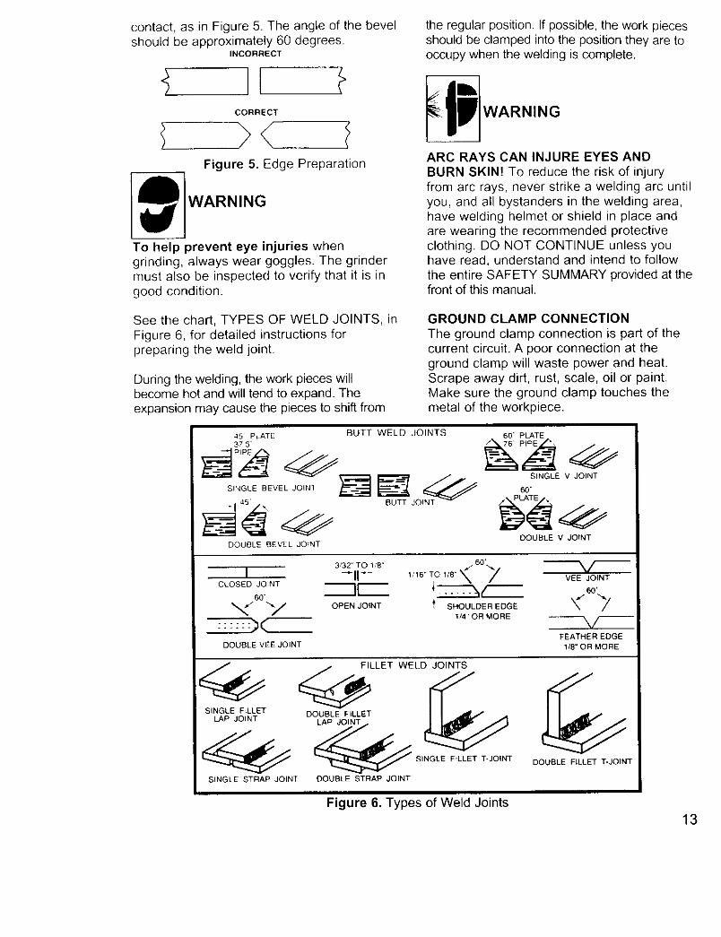
contact,as in Figure5. Theangleof the bevelshouldbeapproximately60degrees.
INCORRECT
CORRECT
)< /Figure 5. Edge Preparation
WARNING
To help prevent eye injuries whengrinding, always wear goggles. The grindermust also be inspected to verify that it is ingood condition.
the regular position. If possible, the work piecesshould be clamped into the position they are tooccupy when the welding is complete.
ARC RAYS CAN INJURE EYES ANDBURN SKIN! To reduce the risk of injuryfrom arc rays, never strike a welding arc untilyou, and all bystanders in the welding area,have welding helmet or shield in place andare wearing the recommended protectiveclothing. DO NOT CONTINUE unless youhave read, understand and intend to followthe entire SAFETY SUMMARY provided at thefront of this manual.
See the chart, TYPES OF WELD JOINTS, in
Figure 6, for detailed instructions forpreparing the weld joint.
During the welding, the work pieces willbecome hot and will tend to expand. Theexpansion may cause the pieces to shift from
GROUND CLAMP CONNECTION
The ground clamp connection is part of thecurrent circuit. A poor connection at theground clamp will waste power and heat.Scrape away dirt, rust, scale, oil or paint.Make sure the ground clamp touches themetal of the workpiece.
45 PLATE BUTT WELD JOINTS37 5'
DOUBLE BEVEL JOfNT
" PLATE
SINGLE V JOINT
60"
DOUBLE V JOINT
3/32" TO YB" 1/16" TO 118' *_I --I1"- VEEJOINTCLOSED JOINT I[ _o.
60.
_,/ "*-/ OPEN JOINT _' SHOULDER EDGE _" _//
FEATHER EDGEDOUBLE VEE JOINT 1/8" OR MORE
FILLET WELDJOINT_
_ SINGLE F{LLET T-JOINT DOUBLE FILLET T-JOINT
SINGLE STRAP JOINT DOUBLE STRAP JOINT
Figure 6. Types of Weld Joints13
LEARNING TO WELD
MIG (Metal Inert Gas) welding is the processof uniting metallic parts by heating andallowing the metals to flow together throughthe use of an electrical arc. The electrical arcis created between a continuous consumablewire electrode (the welding wire) and thework piece. An inert shielding gas is used toprotect the weld puddle from contaminationand enhance the welding capabilities of theelectrical arc.
Whether you have welded before or not, it isimportant that you become familiar with yournew welder, its controls, and the results
achieved at different settings. We stronglyrecommend that you practice with your newwelder on scrap metal trying different heatsettings, base metal thicknesses, and weld-ing positions for each type and size of wireyou will be using. By doing this you will gaina feel for how changes in these weldingvariables affect the weld.
Of course, if you have not welded before,you will need to develop welding skills andtechniques as well.
The self-taught welder learns through aprocess of trial and error. The best way toteach yourself how to weld is with shortperiods of practice at regular intervals. Allpractice welds should be done on scrapmetal that can be discarded. Do not attemptto make any repairs on valuable equipmentuntil you have satisfied yourself that yourpractice welds are of good appearance andfree of slag or gas inclusions. What you failto learn through practice will be learnedthrough mistakes and re-welds later on.
HOLDING THE GUN
The best way to hold the welding gun is theway that feels most comfortable to you.While practicing to use your new welder,experiment holding the gun in differentpositions until you find the one that seems towork best for you.
Position the Gun to the Work PieceThere are two angles of the gun nozzle inrelation to the work piece that must be con-sidered when welding.
14
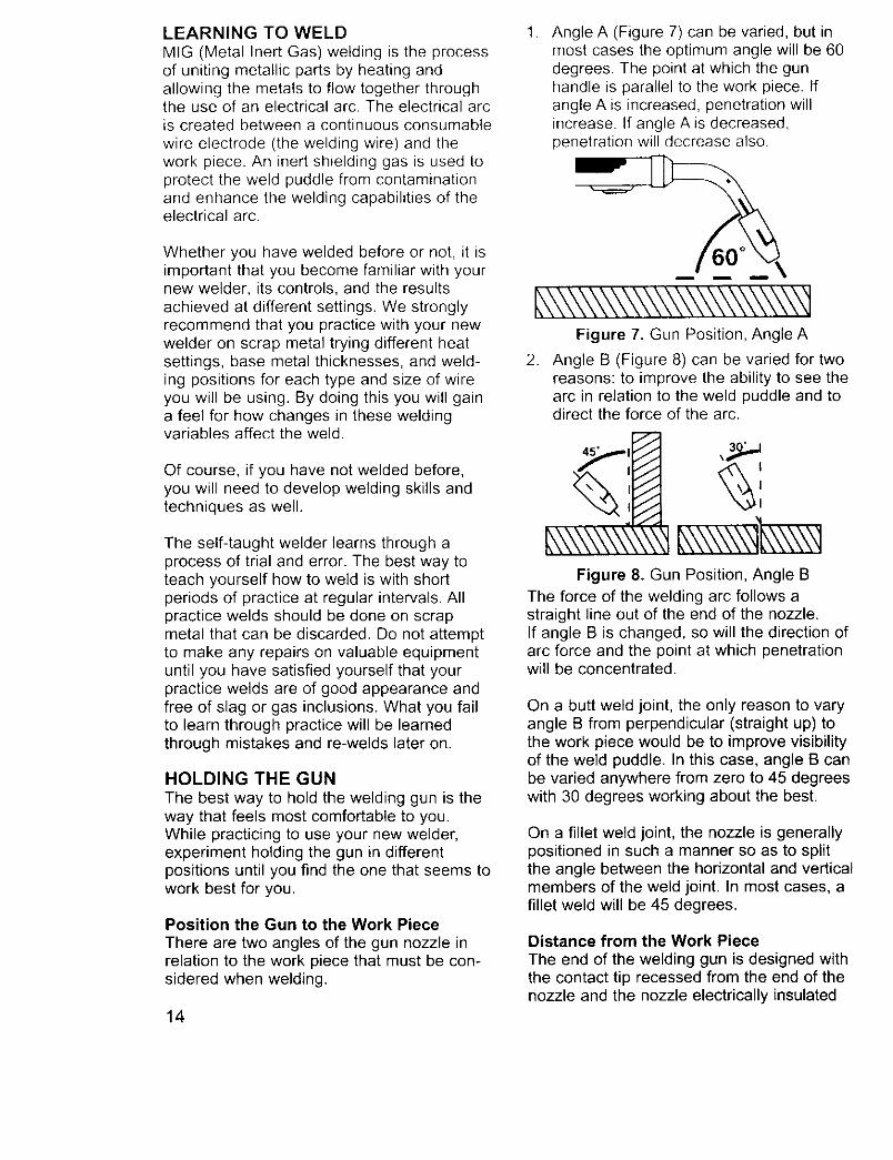
1. Angle A (Figure 7) can be varied, but inmost cases the optimum angle will be 60degrees. The point at which the gunhandle is parallel to the work piece. Ifangle A is increased, penetration willincrease. If angle A is decreased,penetration will decrease also.
L\\\\\\\\\\\\\\\\\\\\\\\qFigure 7. Gun Position, Angle A
. Angle B (Figure 8) can be varied for tworeasons: to improve the ability to see thearc in relation to the weld puddle and todirect the force of the arc.
45 ° I
#,\\\\\\\\\\\'tFigure 8. Gun Position, Angle B
The force of the welding arc follows astraight line out of the end of the nozzle.If angle B is changed, so will the direction ofarc force and the point at which penetrationwill be concentrated.
Qn a butt weld joint, the only reason to varyangle B from perpendicular (straight up) tothe work piece would be to improve visibilityof the weld puddle. In this case, angle B canbe varied anywhere from zero to 45 degreeswith 30 degrees working about the best.
On a fillet weld joint, the nozzle is generallypositioned in such a manner so as to splitthe angle between the horizontal and verticalmembers of the weld joint. In most cases, afillet weld will be 45 degrees.
Distance from the Work Piece
The end of the welding gun is designed withthe contact tip recessed from the end of thenozzle and the nozzle electrically insulated
fromthe restof the gun.Thispermitstheoperatorto actuallyrestthe nozzleon theworkpieceand dragit alongwhilewelding.Thiscanbeveryhelpfulto beginningweldersto steadythe gun,allowingthe welderto con-centrateonweldingtechnique.If the nozzleisheldoff the workpiece,thedistancebetweenthe nozzleand theworkpieceshouldbekeptconstantandshouldnotexceed1/4 inchorthearcmaybeginsputtering,signalinga lossinweldingperformance
LAYING A BEAD
EXPOSURE TO A WELDING ARC ISEXTREMELY HARMFUL TO THE EYES
AND SKIN! Prolonged exposure to the weld-ing arc can cause blindness and burns.Never strike an arc or begin welding until youare adequately protected. Wear flameproofwelding gloves, a heavy long sleeved shirt,cuffless trousers, high topped shoes and awelding helmet.
_ WARNING
ELECTRIC SHOCK CAN KILL! To preventELECTRIC SHOCK, do not perform anywelding while standing, kneeling, or lyingdirectly on the grounded work.
WELDING TECHNIQUES
TRAVELING THE GUNGun travel refers to the movement of the gunalong the weld joint and is broken into two ele-ments: Direction and Speed. A solid weld beadrequires that the welding gun be movedsteadily and at the right speed along the weldjoint. Moving the gun too fast, too slow, orerratically will prevent proper fusion or create alumpy, uneven bead.
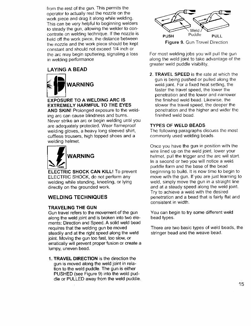
1. TRAVEL DIRECTION is the direction the
gun is moved along the weld joint in rela-tion to the weld puddle. The gun is eitherPUSHED (see Figure 9) into the weld pud-dle or PULLED away from the weld puddle.
PUSH Puddle PULL
Figure 9. Gun Travel Direction
For most welding jobs you will pull the gunalong the weld joint to take advantage of thegreater weld puddle visibility.
, TRAVEL SPEED is the rate at which the
gun is being pushed or pulled along theweld joint. For a fixed heat setting, thefaster the travel speed, the lower thepenetration and the lower and narrowerthe finished weld bead. Likewise, the
slower the travel speed, the deeper thepenetration and the higher and wider thefinished weld bead.
TYPES OF WELD BEADS
The following paragraphs discuss the mostcommonly used welding beads.
Once you have the gun in position with thewire lined up on the weld joint, lower yourhelmet, pull the trigger and the arc will start.In a second or two you will notice a weldpuddle form and the base of the beadbeginning to build. It is now time to begin tomove with the gun. If you are just learning toweld, simply move the gun in a straight lineand at a steady speed along the weld joint.Try to achieve a weld with the desiredpenetration and a bead that is fairly flat andconsistent in width.
You can begin to try some different weldbead types.
There are two basic types of weld beads, thestringer bead and the weave bead.
15
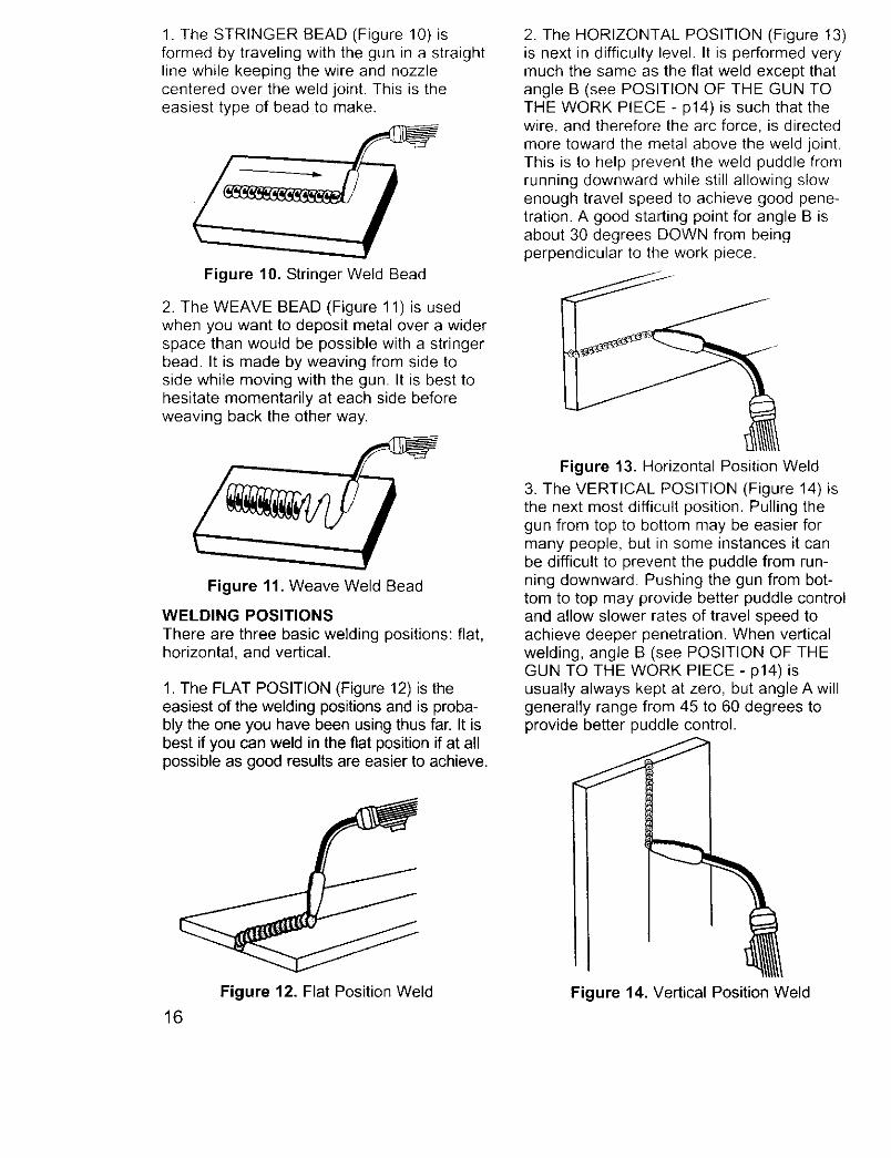
1. The STRINGER BEAD (Figure 10) isformed by traveling with the gun in a straightline while keeping the wire and nozzlecentered over the weld joint. This is theeasiest type of bead to make.
Figure 10. Stringer Weld Bead
2. The WEAVE BEAD (Figure 11) is usedwhen you want to deposit metal over a widerspace than would be possible with a stringerbead. It is made by weaving from side toside while moving with the gun. It is best tohesitate momentarily at each side beforeweaving back the other way.
Figure 11. Weave Weld Bead
WELDING POSITIONS
There are three basic welding positions: flat,horizontal, and vertical.
1. The FLAT POSITION (Figure 12) is theeasiest of the welding positions and is proba-bly the one you have been using thus far. It isbest if you can weld in the fiat position if at allpossible as good results are easier to achieve.
2. The HORIZONTAL POSITION (Figure 13)is next in difficulty level. It is performed verymuch the same as the flat weld except thatangle B (see POSITION OF THE GUN TOTHE WORK PIECE - p14) is such that thewire, and therefore the arc force, is directedmore toward the metal above the weld joint.This is to help prevent the weld puddle fromrunning downward while still allowing slowenough travel speed to achieve good pene-tration. A good starting point for angle B isabout 30 degrees DOWN from beingperpendicular to the work piece.
Figure 13. Horizontal Position Weld
3. The VERTICAL POSITION (Figure 14) isthe next most difficult position. Pulling thegun from top to bottom may be easier formany people, but in some instances it canbe difficult to prevent the puddle from run-ning downward. Pushing the gun from bot-tom to top may provide better puddle controland allow slower rates of travel speed toachieve deeper penetration. When verticalwelding, angle B (see POSITION OF THEGUN TO THE WORK PIECE - p14) isusually always kept at zero, but angle A willgenerally range from 45 to 60 degrees toprovide better puddle control.
Figure 12. Flat Position Weld
16
Figure 14. Vertical Position Weld
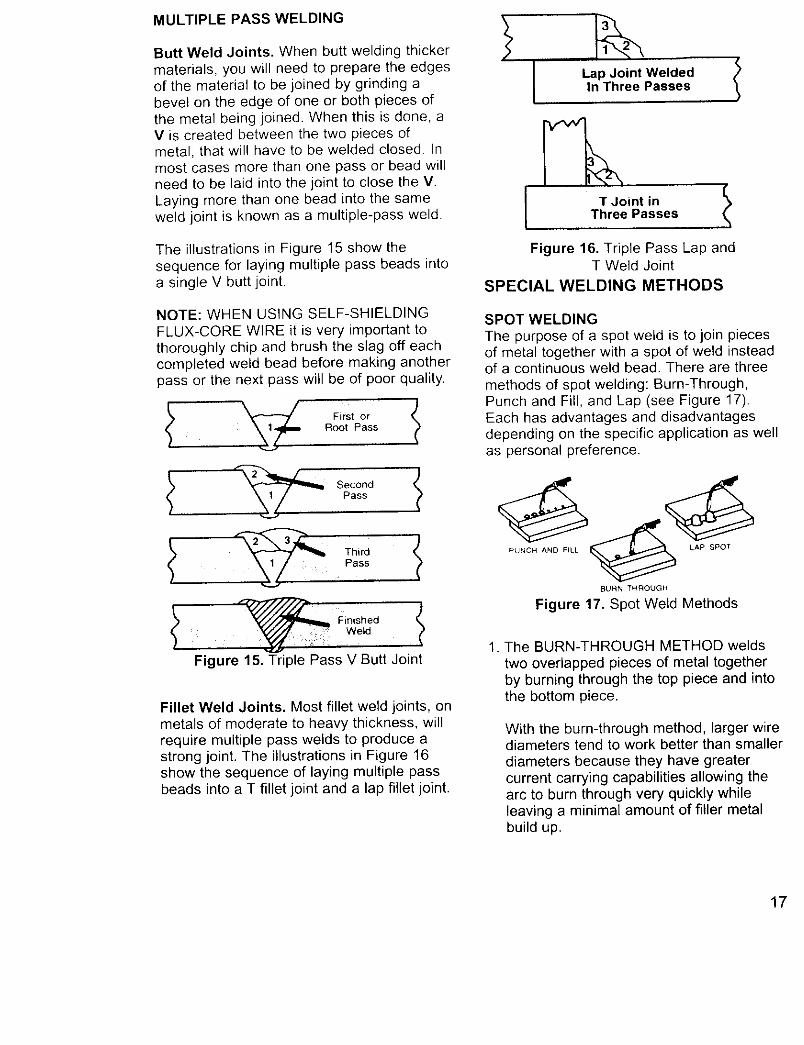
MULTIPLE PASS WELDING
Butt Weld Joints. When butt welding thickermaterials, you will need to prepare the edgesof the material to be joined by grinding abevel on the edge of one or both pieces ofthe metal being joined. When this is done, aV is created between the two pieces ofmetal, that will have to be welded closed. Inmost cases more than one pass or bead willneed to be laid into the joint to close the V.Laying more than one bead into the sameweld joint is known as a multiple-pass weld.
The illustrations in Figure 15 show thesequence for laying multiple pass beads intoa single V butt joint.
NOTE: WHEN USING SELF-SHIELDINGFLUX-CORE WIRE it is very important tothoroughly chip and brush the slag off eachcompleted weld bead before making anotherpass or the next pass will be of poor quality.
First orRoot Pass
FinishedWeld
Figure 15. Triple Pass V Butt Joint
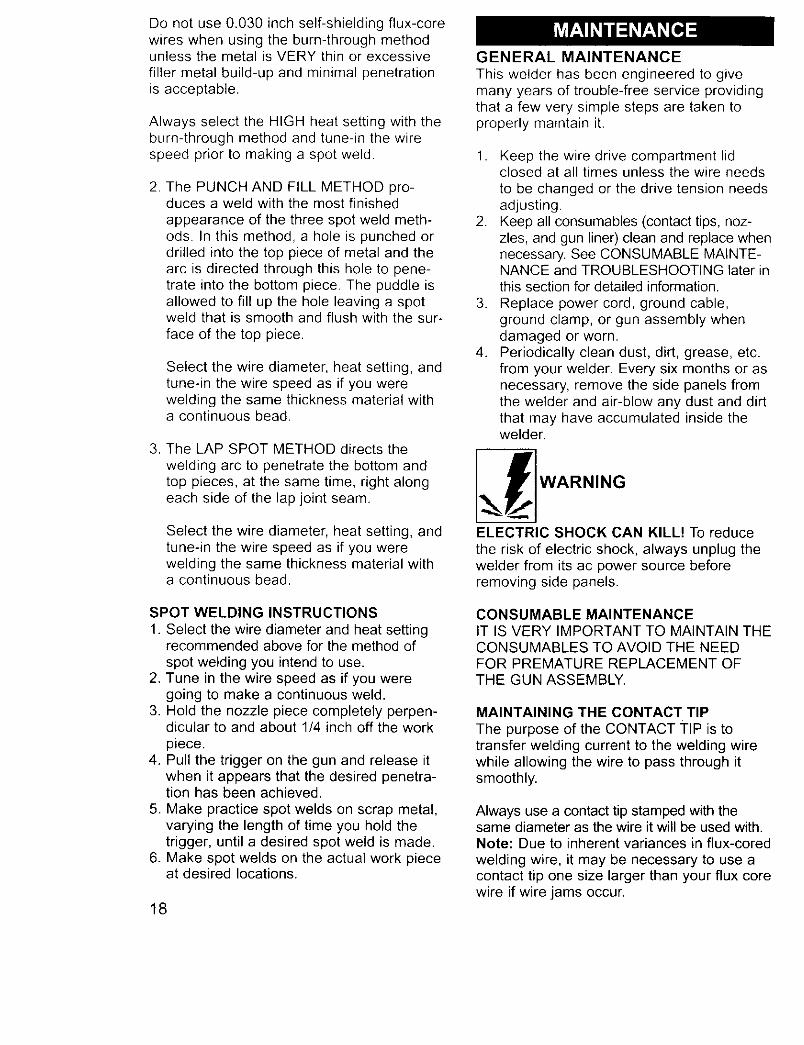
Fillet Weld Joints. Most fillet weld joints, onmetals of moderate to heavy thickness, willrequire multiple pass welds to produce astrong joint. The illustrations in Figure 16show the sequence of laying multiple passbeads into a T fillet joint and a lap fillet joint.
Lap Joint WeldedIn Three Passes
f
T Joint inThree Passes
Figure 16. Triple Pass Lap andT Weld Joint
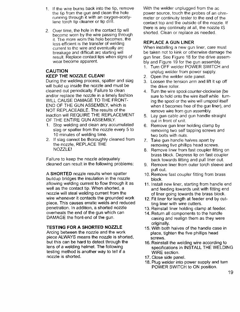
SPECIAL WELDING METHODS
SPOT WELDINGThe purpose of a spot weld is to join piecesof metal together with a spot of weld insteadof a continuous weld bead. There are three
methods of spot welding: Bum-Through,Punch and Fill, and Lap (see Figure 17).Each has advantages and disadvantagesdepending on the specific application as wellas personal preference.
PUNCH AND FILL _ LAP SPOT
BURN THROUGH
Figure 17. Spot Weld Methods
1. The BURN-THROUGH METHOD weldstwo overlapped pieces of metal togetherby burning through the top piece and intothe bottom piece.
With the burn-through method, larger wirediameters tend to work better than smallerdiameters because they have greatercurrent carrying capabilities allowing thearc to burn through very quickly whileleaving a minimal amount of filler metalbuild up.
17
Do not use 0.030 inch self-shielding flux-corewires when using the burn-through methodunless the metal is VERY thin or excessivefiller metal build-up and minimal penetrationis acceptable.
Always select the HIGH heat setting with theburn-through method and tune-in the wirespeed prior to making a spot weld.
2. The PUNCH AND FILL METHOD pro-duces a weld with the most finished
appearance of the three spot weld meth-ods. In this method, a hole is punched ordrilled into the top piece of metal and thearc is directed through this hole to pene-trate into the bottom piece. The puddle isallowed to fill up the hole leaving a spotweld that is smooth and flush with the sur-
face of the top piece.
Select the wire diameter, heat setting, andtune-in the wire speed as if you werewelding the same thickness material witha continuous bead.
3. The LAP SPOT METHOD directs thewelding arc to penetrate the bottom andtop pieces, at the same time, right alongeach side of the lap joint seam.
Select the wire diameter, heat setting, andtune-in the wire speed as if you werewelding the same thickness material witha continuous bead.
SPOT WELDING INSTRUCTIONS
1. Select the wire diameter and heat settingrecommended above for the method of
spot welding you intend to use.2. Tune in the wire speed as if you were
going to make a continuous weld.3. Hold the nozzle piece completely perpen-
dicular to and about 1/4 inch off the workpiece.
4. Pull the trigger on the gun and release itwhen it appears that the desired penetra-tion has been achieved.
5. Make practice spot welds on scrap metal,varying the length of time you hold thetrigger, until a desired spot weld is made.
6. Make spot welds on the actual work pieceat desired locations.
18
GENERAL MAINTENANCE
This welder has been engineered to givemany years of trouble-free service providingthat a few very simple steps are taken toproperly maintain it.
1. Keep the wire drive compartment lidclosed at all times unless the wire needsto be changed or the drive tension needsadjusting.
2. Keep all consumables (contact tips, noz-zles, and gun liner) clean and replace whennecessary. See CONSUMABLE MAINTE-NANCE and TROUBLESHOOTING later inthis section for detailed information.
3. Replace power cord, ground cable,ground clamp, or gun assembly whendamaged or worn.
4. Periodically clean dust, dirt, grease, etc.from your welder. Every six months or asnecessary, remove the side panels fromthe welder and air-blow any dust and dirtthat may have accumulated inside thewelder.
flWARNIN G
ELECTRIC SHOCK CAN KILL! To reduce
the risk of electric shock, always unplug thewelder from its ac power source beforeremoving side panels.
CONSUMABLE MAINTENANCEIT IS VERY IMPORTANT TO MAINTAIN THECONSUMABLES TO AVOID THE NEEDFOR PREMATURE REPLACEMENT OFTHE GUN ASSEMBLY.
MAINTAINING THE CONTACT TIP
The purpose of the CONTACT TIP is totransfer welding current to the welding wirewhile allowing the wire to pass through itsmoothly.
Always use a contact tip stamped with thesame diameter as the wire it will be used with.Note: Due to inherent variances in flux-coredwelding wire, it may be necessary to use acontact tip one size larger than your flux corewire if wire jams occur.
, If the wire burns back into the tip, removethe tip from the gun and clean the holerunning through it with an oxygen-acety-lene torch tip cleaner or tip drill.
. Over time, the hole in the contact tip willbecome worn by the wire passing throughit. The more worn this hole becomes, theless efficient is the transfer of weldingcurrent to the wire and eventually arcbreakage and difficult arc starting willresult. Replace contact tips when signs ofwear become apparent.
CAUTIONKEEP THE NOZZLE CLEAN!
During the welding process, spatter and slagwill build up inside the nozzle and must becleaned out periodically. Failure to cleanand/or replace the nozzle in a timely fashionWILL CAUSE DAMAGE TO THE FRONT-END OF THE GUN ASSEMBLY, which isNOT REPLACEABLE. The results of theinaction will REQUIRE THE REPLACEMENTOF THE ENTIRE GUN ASSEMBLY.
1. Stop welding and clean any accumulatedslag or spatter from the nozzle every 5 to10 minutes of welding time.
2. If slag cannot be thoroughly cleaned fromthe nozzle, REPLACE THENOZZLE!
Failure to keep the nozzle adequatelycleaned can result in the following problems:
A SHORTED nozzle results when spatterbuildup bridges the insulation in the nozzleallowing welding current to flow through it aswell as the contact tip. When shorted, anozzle will steal welding current from thewire whenever it contacts the grounded workpiece. This causes erratic welds and reducedpenetration. In addition, a shorted nozzleoverheats the end of the gun which canDAMAGE the front-end of the gun.
TESTING FOR A SHORTED NOZZLE
Arcing between the nozzle and the workpiece ALWAYS means the nozzle is shorted,but this can be hard to detect through thelens of a welding helmet. The followingtesting method is another way to tell if anozzle is shorted.
With the welder unplugged from the acpower source, touch the probes of an ohm-meter or continuity tester to the end of thecontact top and the outside of the nozzle. Ifthere is any continuity at all, the nozzle ISshorted. Clean or replace as needed.
REPLACE A GUN LINER
When installing a new gun liner, care mustbe taken not to kink or otherwise damage thegun liner. See Figure 18 for the drive assem-bly and Figure 19 for the gun assembly.1. Turn OFF welder POWER SWITCH and
unplug welder from power supply.2. Open the welder side panel.3. Loosen the tension arm and lift it up off
the drive roller.
4. Turn the wire spool counter-clockwise (besure to hold onto the wire itself while turn-
ing the spool or the wire will unspool itselfwhen it becomes free of the gun liner), andremove wire from gun assembly.
5. Lay gun cable and gun handle straightout in front of unit.
6. Remove gun liner holding clamp byremoving two self tapping screws andtwo bolts with nuts.
7. Take gun handle halves apart byremoving five phillips head screws.
8. Remove liner from fast coupler fitting onbrass block. Depress lip on fast couplerback towards fitting and pull liner out.
9. Remove liner from outer torch sleeve and
pull out.10. Remove fast coupler fitting from brass
block.
11. Install new liner, starting from handle endand feeding towards unit with fitting endof liner going towards the brass block.
12. Fit liner for length at feeder end by cut-ting liner with wire cutters.
13. Reinstall liner holding clamp at feeder.14. Return all components to the handle
casing and realign them as they wereoriginally.
15. With both halves of the handle case in
place, tighten the five phillips headscrews.
16. Reinstall the welding wire according tospecifications in INSTALL THE WELDINGWIRE section.
17. Close side panel.18. Plug welder into power supply and turn
POWER SWITCH to ON position.19
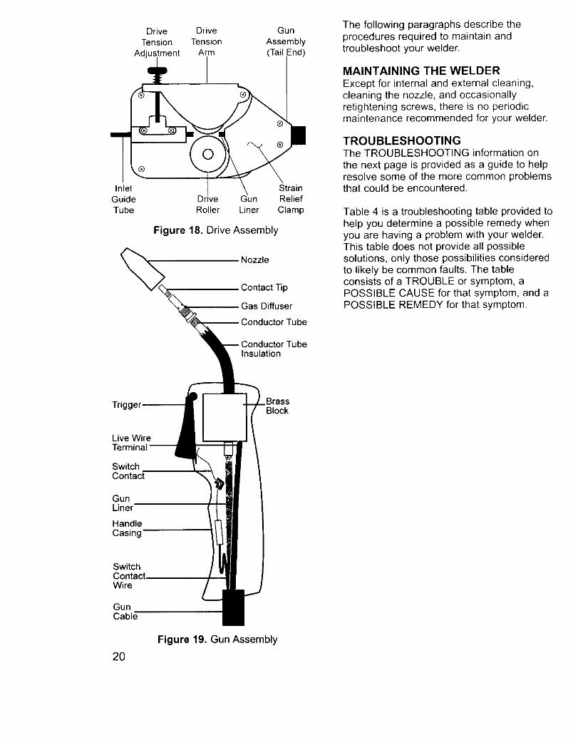
InletGuide
Tube
Drive DriveTension Tension
Adjustment Arm
Gun
Assembly(Tail -nd)
Strain
Drive Gun Relief
Roller Liner Clamp
Figure 18. Drive Assembly
Nozzle
Contact Tip
Gas Diffuser
3onductor Tube
TubeInsulation
The following paragraphs describe theprocedures required to maintain andtroubleshoot your welder.
MAINTAINING THE WELDER
Except for internal and external cleaning,cleaning the nozzle, and occasionallyretightening screws, there is no periodicmaintenance recommended for your welder.
TROUBLESHOOTINGThe TROUBLESHOOTING information on
the next page is provided as a guide to helpresolve some of the more common problemsthat could be encountered,
Table 4 is a troubleshooting table provided tohelp you determine a possible remedy whenyou are having a problem with your welder.This table does not provide all possiblesolutions, only those possibilities consideredto likely be common faults. The tableconsists of a TROUBLE or symptom, aPOSSIBLE CAUSE for that symptom, and aPOSSIBLE REMEDY for that symptom.
Trigger 3rassBlock
Live Wire
SwitchContact
GunLiner
HandleCasing
SwitchContact.Wire
GunCable
20
Figure 19. Gun Assembly
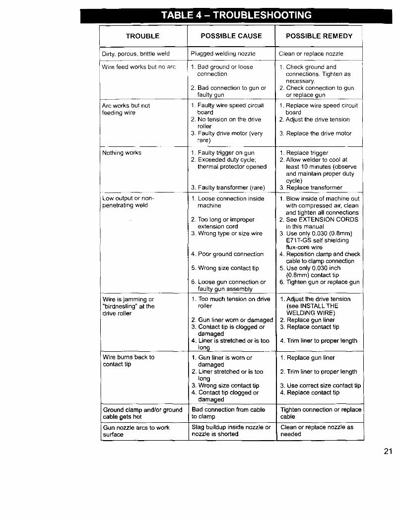
TROUBLE
Dirty, porous, brittle weld
Wire feed works but no arc
Arc works but not
feeding wire
Nothing works
Low output or non-)enetrating weld
Wire is jamming or"birdnesting" at thedrive roller
Wire burns back to
i contact tip
POSSIBLE CAUSE
Plugged welding nozzle
1. Bad ground or looseconnection
2. Bad connection to gun orfaulty gun
1. Faulty wire speed circuitboard
2. No tension on the driveroller
3. Faulty drive motor (veryrare)
1. Faulty trigger on gun2. Exceeded duty cycle;
thermal protector opened
3. Faulty transformer (rare)
1. Loose connection insidemachine
2. Too long or improperextension cord
3. Wrong type or size wire
4. Poor ground connection
5. Wrong size contact tip
6. Loose gun connection orfaulty gun assembly
1. Too much tension on drivemiler
2. Gun liner worn or damaged3. Contact tip is clogged or
damaged4, Liner is stretched or is too
long1. Gun liner is worn or
damaged2. Liner stretched or is too
long3. Wrong size contact tip4. Contact tip clogged or
damaged
POSSIBLE REMEDY
Clean or replace nozzle
1 Check ground andconnections. Tighten as
necessary.2. Check connection to gun
or replace gun
1. Replace wire speed circuitboard
2. Adjust the drive tension
3. Replace the drive motor
1. Replace trigger2. Allow welder to cool at
least 10 minutes (observeand maintain proper dutycycle)
3. Replace transformer
1. Blow inside of machine outwith compressed air, cleanand tighten all connections
2. See EXTENSION CORDSin this manual
3. Use only 0.030 (0.8mm)E71T-GS self shieldingflux-core wire
4. Reposition clamp and checkcable to clamp connection
5. Use only 0.030 inch(0.8mm) contact tip
6. Tighten gun or replace gun
1. Adjust the drive tension(see INSTALL THEWELDING WIRE)
2. Replace gun liner3. Replace contact tip
4. Tdm liner to proper length
1. Replace gun liner
2. Trim liner to proper length
3. Use correct size contact tip4. Replace contact tip
Ground clamp and/or ground Bad connection from cable -Rghtenconnectionor replacecable gets hot to clamp cable
Gun nozzle arcs to work Slag buildup inside nozzle or Clean or replace nozzle assurface nozzle is shorted needed
21

No. Code Description Qty.
01 WE20568-2160003602 WE20568-0500006203 WE20568-0500006104 WE20568-3372010805 WE20568-0500006306 WE20568-0500006407 WE20568-4412010008 WE20568-4413509709 WE20568-0460010809a WE20568-2169027010 WE20568-2240008311 WE20568-0460011312 WE20568-2220003613 WE20568-2220003514 WE20568-4440001815 WE20568-2300008016 WE20568-2271000117 WE20568-2022001818 WE20568-2160501019 WE20568-4321014720 WE20568-2211000521 WE20568-2169000122 WE20568-2169031023 WE20568-0460014424 WE20568-3380507425 WE20568-2169027826 WE20568-2102001727 WE20568-2102001828 WE20568-2103001029 WE20568-2102000830 WE20568-2102002631 WE20568-2103500232 WE20568-2102501133 WE20568-2102005734 WE20568-2102005635 WE20568-2102005936 WE20568-2100000537 WE20568-2102502938 WE20568-2102004739 WE20568-7760031440 WE20568-2190500241 WE20568-2190500742 WE20568-21905011
Welder Handle 1Right Upper Panel 1FronVLower Panel 1Dividing Panel 1Left Side Panel 1Removable Access Panel 1Transformer 60Hz 115V 50x70AL 1Choke _3.9 40x25AL 1Kit Spool Holder for _16 Spools-Comp. 1Locking Pin for Spool Holder 1Rectifier PMS 30B F/1 Type 1Complete Thermostat 100 ° +Support 1Red Voltage Switch 1Yellow Power Switch 16A-250V 1Plastic Wire Feeder _28 06-08 ROL 1Gun 8mm 2 1EC. Board E0585.1 220V 1Power Cord 3x4WG14 MT. 2.5 1Cable Clamp For Hole 020 2Ground Cable 10MM 2 1Ground Clamp 120A 1Gun Grommet on Front Panel 1Red Wire Feed Speed Knob 1Wire Feeding Motor _28 +Pinion 1Wire Feed Roller _7x25.023-.030 1Gun Pressure Cover 1Self-Tapping Screw for Cabinet 16Self-Tapping Screw for Transformer &Choke 8Washer for Transformer & Choke 8Self-Tapping Screw for Thermostat 2Self-Tapping Screw for Spool Holder 1Gear Washer for Spool Holder 5Hex Nut for Rectifier 1Self-Tapping Screw for Wire Feeder 2Self-Tapping Screw for Wire Feeder 2Self-Tapping Screw for Wire Feeder 1TE Screw 1Hex Nut 2Self-Tapping Screw for Handle 2Suggested Settings Label 1Plastic Welding Mask 1Dark Glass for Welding Mask 1Hammer Brush 1
22
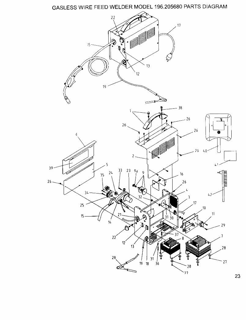
GASLESS WIRE FEED WELDER MODEL 196.205680 PARTS DIAGRAM
22
13
12
1
26
33 23 9a24
26
,1710
11
29
1213
2'7
23
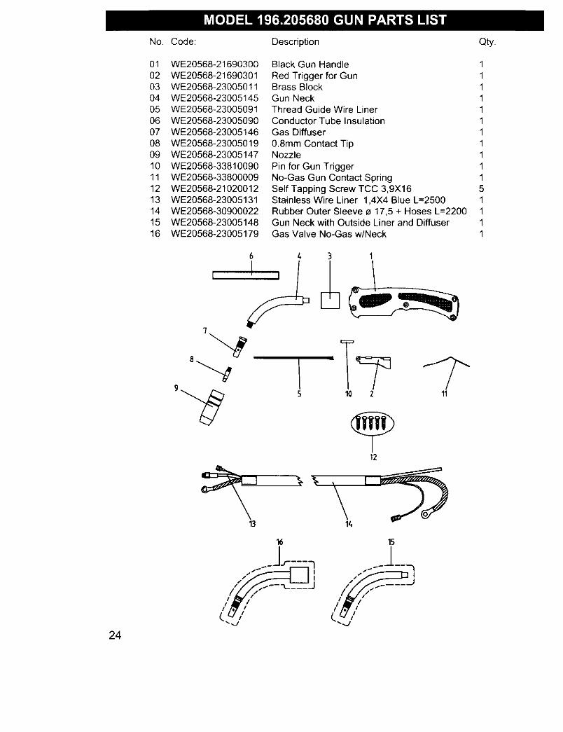
No. Code: Description Qty.
01 WE20568-2169030002 WE20568-2169030103 WE20568-2300501104 WE20568-2300514505 WE20568-2300509106 WE20568-2300509007 WE20568-2300514608 WE20568-2300501909 WE20568-2300514710 WE20568-3381009011 WE20568-3380000912 WE20568-2102001213 WE20568-2300513114 WE20568-3090002215 WE20568-2300514816 WE20568-23005179
Black Gun Handle 1
Red Trigger for Gun 1Brass Block 1Gun Neck 1Thread Guide Wire Liner 1Conductor Tube Insulation 1Gas Diffuser 1
0.8mm Contact Tip 1Nozzle 1
Pin for Gun Trigger 1No-Gas Gun Contact Spring 1Self Tapping Screw TCC 3,9X16 5Stainless Wire Liner 1,4X4 Blue L=2500 1Rubber Outer Sleeve _ 17,5 + Hoses L--2200 1Gun Neck with Outside Liner and Diffuser 1Gas Valve No-Gas w/Neck 1
3 1
12
13
24
16
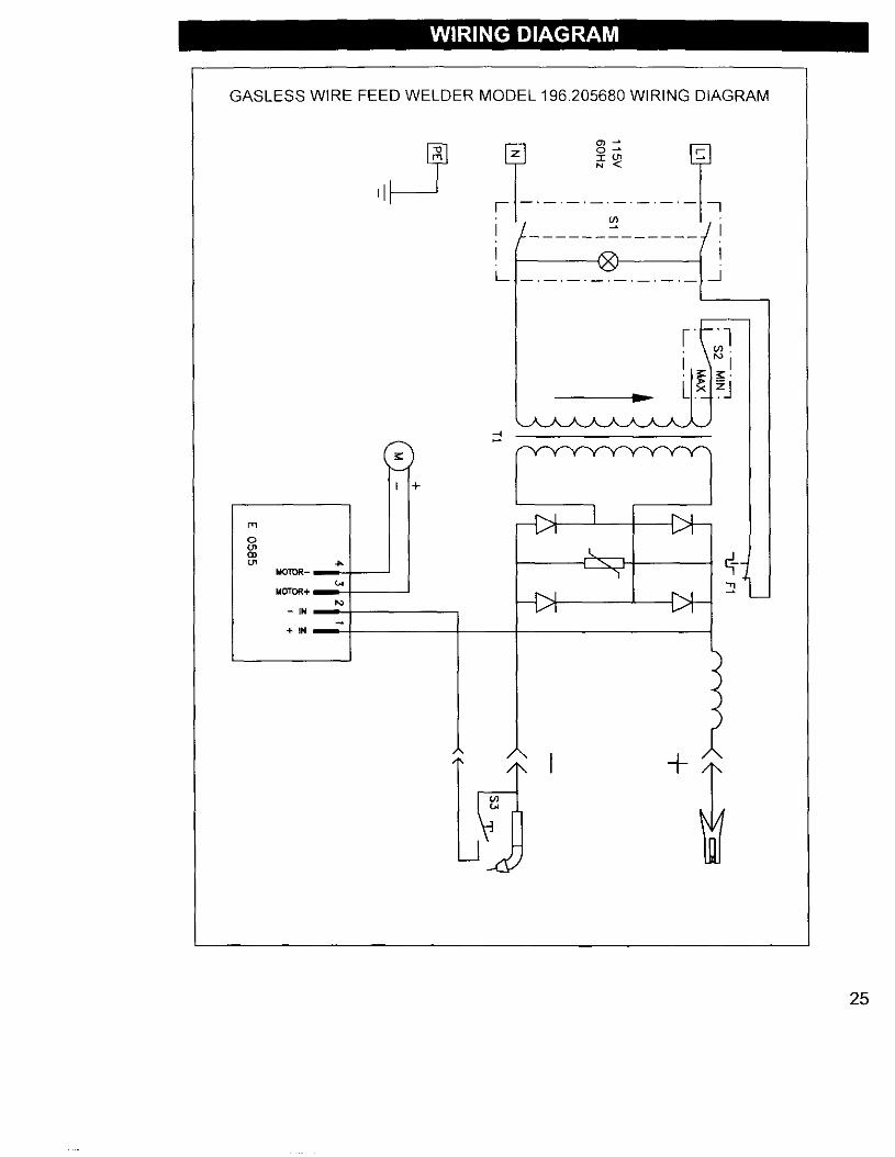
GASLESS WIRE FEED WELDER MODEL 196205680 WIRING DIAGRAM
m
oolCoc.n _,
MOTOR-
MOTOR+
- IN --
'+IN
......W ............... I _
i
I +
25
Poo_
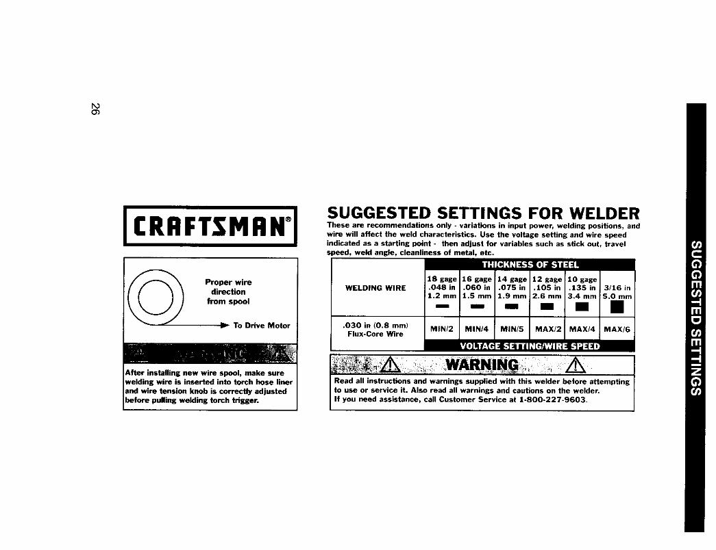
JCRRFTSMAN°ISUGGESTED SETTINGS FOR WELDERThese are recommendations only - variations in input power, welding positions, andwire will affect the weld characteristics. Use the voltage setting and wire speedindicated as a starting point - then adjust for variables such as stick out, travelspeed, weld angle, cleanliness of metal, etc.
Proper wiredirection
from spool
_-_ To Drive Motor
After installing new wire spool, make surewelding wire is inserted into torch hose linerand wire tension knob is correctly adjustedbefore pulling welding torch trigger,
WELDING WIRE
.O3O in (0.8 mm) MIN/2 MINI4 MIN/5 MAX/2 MAX/4 MAX/6Flux-Core Wire
I 'L0] II L'TH =1_'1_111d :[eA','Jl:it-1_:_ _
Read all instructions and warnings SUpplied with this welder before attemptingto use or service it. Also read all warnings and cautions on the welder.If you need assistance, call Customer Service at 1-800-227-9603.
Garantia limitada de Craftsman ............ 27indice ........................................................ 27Resumen de Seguridad .......................... 28
Informacion Importante deSeguridad ............................................ 28
Riesgos de Choque Electrico .............. 29Riesgos de Destello del Arce .............. 29Riesgos de Incendio ............................ 30Riesgos de Vapores ............................ 31Informaci6n Adicional de Seguridad ..32
Conozca su Soldadora .......................... 33Ensamblaje .............................................. 34
Desembalaje de la Soldadora .............. 34Lista de Empaque .................................. 34Instalacion del Asa ................................ 34Ensamblaje de la Careta para Soldar ..34Conexion al Suministro Electrice .......... 34Cordenes de Extension ........................ 35Selecci6n del Alambre Soldador .......... 35Instalaci6n del Alambre soldador .......... 35
Operacion ................................................ 36Descripcion ............................................ 36Ciclo de Funcionamiento ...................... 36Pretecci6n Termica Interna .................. 37Controles e Indicadores ........................ 37Preparaciones para Soldar .................... 37Preparacion de la Pieza de Trabajo ......37Preparaci6n de la Junta ........................ 37Conexi6n de la Pinza a Tierra .............. 38Aprendiendo a Soldar ............................ 39Come Sujetar la Pistola ........................ 39
Posici6n de la Pistola con laPieza de Trabajo ................................ 39Distancia de la Pieza de Trabajo ........ 39
Come Formar el Cord6n de Soldadura 40Tecnicas para Soldar .......................... 40
Desplazamiento de la Pistola .............. 40Tipos de Cordones de Seldadura ......40Posiciones para Soldar ...................... 41Soldadura de Pasadas MUltiples ........ 42
Metodos Especiales para Soldar .......... 42Soldadura de Puntos ............................ 42
Instrucciones para laSoldadura de Puntes .......................... 43
Mantenimiento ........................................ 43Mantenimiento General ........................ 43
Mantenimiento de Insumos ................ 43Mantenimiento de laPunta de Contacto .............................. 43Prueba de Cortocircuito en laBoquilla .............................................. 44
Cambio del Forro de la Pistola ............ 44Mantenimiento de la Soldadura ............ 45Diagn6stico de Problemas .................... 46
Lista de Piezas ........................................ 47Diagrama de Cableado .......................... 50Graduaciones Sugeridas ...................... 51
Garantia limitada de Tres Aries de la SoldadoraCraftsman
Si cualquier parte de esta soldadora, exceptoper la pistola o los cables, fallase debido a undefecto de materiales o de fabricacion durantetres afios a partir de la fecha de compra,devolverla al Centro de Reparaciones yRepuestos de Sears mas cercano y Sears lareparara sin costo alguno. Sears reparara lapistola o los cables sin costo alguno solodurante el periodo de un afio a partir de lafecha de compra. Esta garantia no cubre laspiezas que se gastan como las puntas decontacto o boquillas, que se consumen durantela operaci6n normal de la soldadura. Estagarantia se aplica solo cuando la unidad seusa en los Estados Unidos. Esta garant[aotorga derechos especificos y usted tambienpodria tener otros derechos que varian de unEstado a otro.
Sears, Roebuck and Co., D/817WA, HoffmanEstates, IL 60179
27
Todo artesano respeta las herramientas con lasque trabaja. Sabe que las herramientas
representan a6os de mejoras y desarrolloconstantes. Un verdadero artesano tambien
sabe que las herramientas son peligrosas si seusan mal o se maltratan.
La lectura de este Manual del Operador antes deusar la soldadora, permitir_l hacer un trabajomejor y mas seguro. Aprenda los usos yIimitaciones de la soldadora, asf como lospeligros relacionados con el trabajo desoldadura.
INFORMACION IMPORTANTEDE SEGURIDAD
A continuacion se proveen pautas de seguridadpara ayudarle a operar su soldadora nuevabajo las condiciones m_ls seguras posibles.Cualquier equipo que use energia electricapuede ser potencialmente peligroso cuando nose siguen o se desconocen las instruccionesde seguridad y de manipulaci6n.A continuacion se provee la informaci6nnecesaria para que el usuario opere y use launidad en forma segura.
Un aviso de ADVERTENCIA precediendo unpaso de un procedimiento indica que elsiguiente paso podria lesionar a la persona sies que no se cumplen con las precauciones deseguridad apropiadas.
Un aviso de PRECAUCION precediendo unpaso de un procedimiento indica que elsiguiente paso podria dal_ar el equipo en uso.
Se puede usar una NOTA antes o despues deun paso en un procedimiento para remarcar oexplicar algo propio de ese paso.
LEER TODAS LAS INSTRUCCIONES DESEGURIDAD CUIDADOSAMENTE antes deintentar instalar, operar o darle servicio a estasoldadora, Ignorar estas instrucciones, podriacausar lesiones personales y/o da5os a lapropiedad.
CONSERVAR ESTAS INSTRUCCIONESPAPA REFERENCIA FUTURA,
28
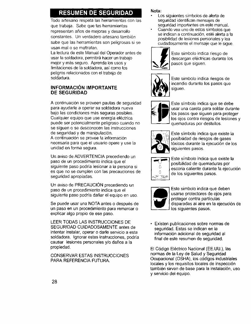
Nota:Los siguientes sfmbolos de alerta deseguridad identifican mensajes deseguridad importantes en este manual.Cuando vea uno de estos simbolos quese indican a continuaci6n, est6 alerta a laposibilidad de lesiones personales y leacuidadosamente el mensaje que le sigue.
s e--ores odedescargas electricas durante lospasos que siguen.
Este simbolo indica riesgos deincendio durante los pasos quesiguen.
Este simbolo indica que se debeusar una careta para soldar durantelos pasos que siguen para protegerlos ojos contra riesgos de lesiones yquemaduras por destellos,
Este simbolo indica que existe laposibilidad de riesgos de gasest6xicos durante la ejecuci6n de lossiguientes pasos.
IT Este simbolo indica que existe laposibilidad de quemaduras porescoria caliente durante la ejecuci6nde los siguientes pasos.
Este simbolo indica que debenusarse protectores de ojos paraproteger contra partfculasdisparadas al aire en la ejecuci6n delos siguientes pasos.
• Existen publicaciones sobre normas deseguridad. Estas se indican en lainformaci6n adicional de seguridad alfinal de este resumen de seguridad.
El C6digo Electrico Nacional (EE.UU.), lasnormas de la Ley de Salud y SeguridadOcupacional (OSHA), los c6digos industrialeslocales y los requisitos locales de inspecci6ntambien sirven de base para la instalaci6n, usoy servicio del equipo.
RIESGOS DE CHEQUE ELECTRICO
_ ADVERTENCIA
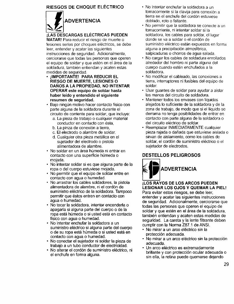
iLAS DESCARGAS ELECTRICAS PUEDENMATAR! Para reducir el riesgo de muerte olesiones serias per cheques electricos, se debeleer, entender y acatar las siguientesinstrucciones de seguridad. Adicionalmente,cerciorarse que todas las personas que operenel equipo de soldar y que esten en el area de lasoldadura, tambien entiendan y acaten estasmedidas de seguridad.• ilMPORTANTE! PARA REDUCIR EL
RIESGO DE MUERTE, LESIONES ODANES A LA PROPIEDAD, NO INTENTAROPERAR este equipo de soldar hastahaber leido y entendido el siguienteresumen de seguridad.
• Bajo ningt_n motive hacer contacto fisico conparte alguna de la soldadora durante elcircuito de corriente para soldar, que incluye:
a. La pieza de trabajo o cualquier materialconductor en contacto con esta,
b. La pinza de conexion a tierra,c. El electrode o alambre de soldar,d. Cualquier otra pieza metalica en el
sujetador del electrode o pistolaalimentadora de alambre.
• No soldar en un area ht]meda ni entrar encontacto con una superficie hQmeda omojada.
• No intentar soldar si es que alguna parte de laropa o del cuerpo estuviese mojada.
• No permitir que el equipo de soldar entre encontacto con agua o humedad.
• No arrastrar los cables soldadores, la pistolaalimentadora de alambre, ni el cord6n desuministro electdco de la soldadora. Tampocopermitir que estos entren en contacto conagua o humedad.
• No tocar la soldadora, intentar encenderla oapagarla si alguna parte del cuerpo o de laropa est& ht]meda o si usted esta en contactofisico con agua o humedad.
• No intentar enchufar la soldadora a unsuministro electrico si alguna parte del cuerpoo de su ropa est_ hOmeda o si usted esta encontacto con agua o humedad.
• No conectar el sujetador ni soldar la pieza detrabajo a un tube conductor de electricidad.
• No alterar el cordon de suministro el6ctrico, niel enchufe en forma alguna.
• No intentar enchufar la soldadora a untomacorriente si la clavija para conexion atierra en el enchufe del cordon estuviesedoblado, rote o faltante.
• No permitir que la soldadora se conecte a untomacorriente, ni intentar soldar si lasoldadora, los cables para soldar, el lugardonde se va a soldar o el cordon de
suministro electrico estan expuestos en formaalguna a precipitacion atmosferica,salpicaduras o chorros de agua salada.
• No cargar los cables de soldadura enrolladosalrededor del hombre ni parte alguna delcuerpo cuando esten enchufados a lasoldadora.
• No modificar el cableado, las conexiones atierra, interruptores ni fusibles del equipo desoldar.
• Usar guantes de soldar para ayudar a aislarlas manes del circuito de soldadura.
• Mantener todos los envases con liquidosalejados Io suficiente de la soldadora y de lazona de trabajo, de mode que si el liquido sederrama no tenga posibilidades de entrar encontacto con parte alguna de la soldadora odel circuito electrico de soldar.
• Reemplazar INMEDIATAMENTE cualquierpieza rajada o dafiada que estuviese aislada osirvan de aislamiento, come los cables desoldar, el cord6n de suministro electrico o elsujetador de electrodes.
DESTELLOS PELIGROSOS
p ADVERTENCIA
iLOS RAYOS DE LOS ARCOS PUEDENLESIONAR LOS OJOS Y QUEMAR LA PIEL!Para evitar estos riesgos, se debe leer,entender y acatar las siguientes instruccionesde seguridad. Adicionalmente, cerciorarse quetodas las personas que operen el equipo desoldar y que esten en el _rea de la soldadura,tambien entiendan y acaten estas medidas deseguridad. La careta y la lente filtrante debencumplir con la Norma Z87.1 de ANSI.• No mirar a un arco el6ctrico sin la
proteccion adecuada.• No mirar a un arco el6ctrico sin la protecciSn
adecuada.• Un arco el_ctrico es extrernadamente
bdllante y con protecci6n ocular adecuada osin ella, la retina puede quemarse dejando
29
una mancha negra permanente en el campode vision. Debe usarse una careta con unlente oscuro No. 10 (minimo).
• No encender el arco de soldar hasta quetodos los observadores y usted (el soldador)tengan puesta su careta de soldar.
• No usar cascos ni caretas rajadas o rotas, yreemplazar inmediatamente los lentesfiltrantes.
• No permita que la parte no aislada de lapistola alimentadora de alambre hagacontacto con la pinza de conexion a tierra ola pieza de trabajo conectada a tierra paraevitar que se forme un arco al hacercontacto.
• Proveer caretas con lente filtrante No. 10 alos observadores.
• Usar ropa protectora. La luz intensa del arcode soldadura puede quemar la piel de lamisma forma que el sol, aun a traves de ropaliviana. Use ropa oscura de material pesade.La camisa que se use debe ser de mangalarga y el cuelle debe mantenerse abotonadepara proteger el peche y el cuelle.
• Preteccion contra los reflejos de los rayos delarco. Los rayos del arco pueden reflejarseen superficies brillantes come las superficiescon pintura brillante, de aluminio, aceroinoxidable y vidrio. Es posible que sus ojosse lesionen per los reflejos de los rayos delarco, aQn cuando se use careta protectora.Si suelda con una superficie reflexiva atr_ssuyo, los rayos del arco pueden rebotar de lasuperficie, luego de los lentes filtrantes alcostado de su careta y de ahi a sus ojos. Siexiste un rondo reflexive en la zona deltrabajo de soldadura, saquelo o cQbralo conalgo no inflamable y no reflexive. Los rayosque reflejan de los arcos tambien puedencausar quemaduras de la piel, ademas delesiones a los ojos.
RIEGOS DE INCENDIO
ADVERTENCIA
iLOS INCENDIOS O EXPLOSIONES PUEDENCAUSAR MUERTE, LESIONES Y DANOS ALA PROPIEDAD! Para evitar estos riesgos, sedebe leer, entender y acatar las siguientesinstrucciones de seguridad. Adicionalmente,cerciorarse que todas las personas que operenel equipo de soldar y que esten en el area dela soldadura, tambien entiendan y acaten estas
30
medidas de seguridad, iRECUERDE! Per sunaturaleza, los arcos de soldar producenchispas, gotean metal derretido y escoriacaliente y pedazos de metal caliente quepueden iniciar incendios, quemar la piel ylesionar los ojos.• No usar guantes ni ropa que contenga aceite,
grasa u otras sustancias inflamables.• No usar preparaciones inflamables en el
cabello.• No soldar en un area hasta haber verificado
que no existan materiales combustibles y/oinflamables. TENER EN CUENTA que laschispas y la escoria puede velar 11 m (35') ypasar per pequeSas rajaduras o aberturas.Si su trabajo y los materiales combustiblesno pueden mantenerse separados un minimode 11 m (35'), protegerlos adecuadamentepara que no se enciendan, colocandolescubiertas protectoras resistentes al fuego.
• No soldar en paredes hasta haber revisadoque no existan materiales combustibleshaciendo contacto al otro lade de las
paredes, y si las hubiese, sacarlas.• No soldar, cortar, ni realizar trabajos similares
en tambores, cilindros, tanques, ni otroscontenedores que hayan contenidosubstancias inflamables o t6xicas. Lastecnicas para evacuar las sustancias yvapores inflamables para que un contenedorquede seguro para soldar o cortar, sonbastante complejas y requierenentrenamiento y capacitacion especial
• No format un arco electrico en un cilindro de
gas o de aire comprimido, ni en contenedorpresurizado alguno; porque se creara un &teaquebradiza que podria causar una rupturaviolenta inmediatamente o en el future comeconsecuencia de una manipulaci6n ruda.
• No soldar ni cortar en una zona donde el aire
pueda contener polvo inflamable (come polvode granos), gases, liquidos o vapores (comede gasolina).
• No agarrar metales calientes come la piezade trabajo o los restos de electrodes con lasmanes desnudas.
• Usar guantes de cuero, camisa gruesa demanga larga, pantalones sin dobladillo obasta, botines que cubran los pies hastaarriba, casco, careta y capa.
• Segun fuese necesario, usar ropa protectoraadicional come saco con mangas de cuero,polainas o mandil resistentes al fuego. Laschispas o metales calientes pueden alojarseen dobladillo de las mangas, la basta de los
pantaloneso losbolsillos.Lospu6osy loscuellosde lascamisasdebenmantenerseabotonadasy sedebeeliminarlosbolsillosdelpechode lacamisa.
• iTenerequiposextintoresde incendioamanoparauso inmediato!SerecomiendaunextintorportatildequimicotipoABC.
• Cuandose sueldeen posicionesporencimade lacabeza,usartaponesdeoidosparaevitarquelaschispaso laescoriacalientecaigandentrode losoidos.
• Asegurarsequeel areadondesesueldatengaunpisobueno,s61idoy seguro,preferiblementedeconcretoo mamposteria,sin Iosetas,alfombrasniotrosmaterialesinflamables.
• Protegerlasparedes,cieloraso,y lospisosdematerialesinflamablesconcobertoresresistentesal calor.
• Antesdeabandonarel Areadondese hasoldado,revisarquenoquedenchispas,metaleso escoriacaliente,ni llamas.
RIESGOS DE VAPORES
ADVERTENCIA
iLAS EMANACIONES, GASES Y VAPORES
PUEDEN CAUSAR INCOMODIDAD,ENFERMEDAD O MUERTE! Para evitar estos
riesgos, se debe leer, entender y acatar lassiguientes instrucciones de seguridad.
Adicionalmente, cerciorarse que todas las
personas que operen el equipo de soldar y queesten en el Area de la soldadura, tambien
entiendan y acaten estas medidas deseguridad.
• No soldar en un area si no hasta despu6s dehaber verificado que tenga ventilacionadecuada seg_n Io descrito en la NormaZ49.1 de ANSI. Si la ventilaci6n no es
adecuada para intercambiar los vapores ygases generados durante el proceso desoldadura con aire fresco, no soldar a menosque usted (el soldador) y todas las otraspersonas en el area de la soldadura usenequipos respiradores autocontenidos.
• No calentar metales cubiertos con o quecontengan materiales que produzcanvapores toxicos (como acero galvanizado), a
menos que primero se saque elrecubrimiento. Asegurarse que el area estebien ventilada y que el operador y todas lasotras personas en el area de la soldadurausen equipos respiradores autocontenidos.
• No soldar, cortar ni calentar plomo, zinc,cadmio, mercurio, berilio, ni metales similaressin asesoramiento profesional y sin haberinspeccionado la ventilaci6n del area dondese va a soldar. Estos metales producenvapores EXTREMADAMENTE TOXICOS quepueden causar incomodidad, enfermedad omuerte.
• No soldar ni cortar en areas donde existansolventes clorinados. Los vapores de loshidrocarbones clorinados tales como el
tricloroetileno y percloroetileno, puedendescomponerse con el calor de un arcoel_ctrico o su radiaci6n ultravioleta. Esto
puede generar fosgeno, un gas altamentetoxico y otros gases irritantes de los ojos ylos pulmones. No soldar ni cortar cuandoestos vapores puedan ingresar al area detrabajo o donde la radiaci6n ultravioletapueda penetrar alas areas que contienenaunque sea peque_as cantidades de esosvapores.
• No soldar en un area confinada a menos queeste bien ventilada o el operador y todas lasotras personas en el area de la soldadurausen equipos respiradores autocontenidos.
• Si se desarrolla una irritaci6n momentanea
de los ojos, nariz o garganta, deje de soldarporque esto significa que la ventilaci6n no esadecuada. Paralice el trabajo y tome lasmedias necesarias para mejorar laventilacion en el area de la soldadura.No reinicie la soldadura si la incomodidadfisica persiste.
31
INFORMACION ADICIONALDE SEGURIDAD
Para informaci6n adicional referente a la
seguridad para soldar, referirse a las siguientesNormas y cumpla con Io que sea aplicable.
• Norma Z49.1 de ANSI-Seguridad para Soldary Cortar: Se puede obtener en la SociedadAmericana de Soldadura, 550 NW Le Jeune,Miami, FL. 33126,telefono (800) 443-9353,fax (305) 443-7559;www.amweld.org o www.aws.org
• Norma Z87.1 de ANSI, Practicas Seguraspara el Trabajo y Educaci6n para laProtecci6n de los Ojos y la Cara:Se puede obtener en elInstituto Nacional Americano de Normas,11 West 42nd Street, New York,New York 10036,telefono (212) 642-4900,fax (212) 398-0023,www.ansi.org
• Norma 51B NSTA, Proceso de Corte ySoldadura: Se puede obtener en laAsociaci6n Nacionalde Protecci6n Contra Incendios,
1 Batterymarch Park,EO. Box 9101, Quince,Ma. 02269-9101,telefono (6t7) 770-3000,fax (617) 770-0700,www.nfpa.org
Norma 29CFR de OSHA, parte 1910,Secci6n Q, Soldadura, Corte y SoldaduraFuerte: Se puede obtener en la oficina deOSHA en su estado, o en la Secretaria deTrabajo de EE.UU.Oficina de Relaciones Publicas,Room N3847, 200 Constitucion Ave.,Washington D.C. 20210,www.osha.gov
Norma W117.2 de CSA, C6digo deSeguridad para Soldar y Cortar:Puede obtenerse de la Asociaci6nCanadiense de Normas,178 Rexdale Boulevard,Etobicoke, Ontario, M9W 1R3,www.csaca
• Norma A6.0 de la Asociaci6n Americana deSoldadura - Soldadura y Corte deContenedores que han ContenidoCombustible:
Se puede obtener de la SociedadAmericana de Soldadura,550 NW Le Jeune Road,Miami, FL 33126,telefeno (800) 443-9353,fax (305) 443-7759,www.amweld.org o www.aws.org
32
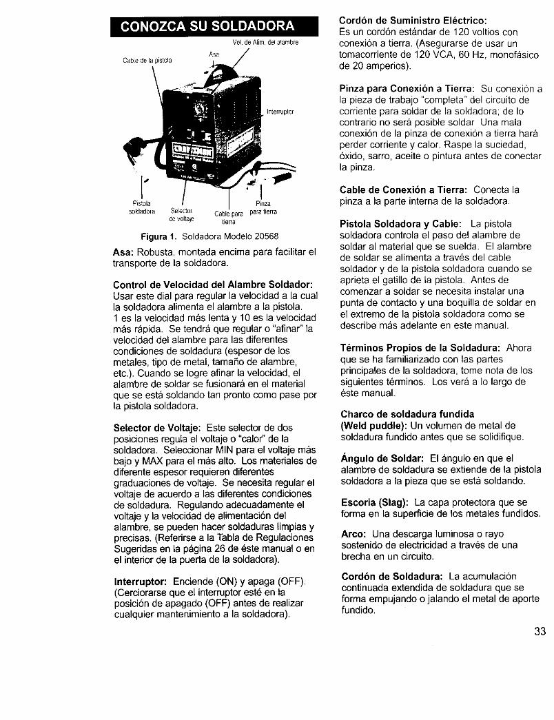
As8CabLe de la pistola
Vel de Alim del aqambre
Interrupter
Pistola
soldadoraPinza
Selector Cablepara paratierrade voltaje tierra
Figura 1. Soldadora Modelo 20568
Asa: Robust& montada encima para facilitar eltransporte de la soldadora.
Control de Velocidad del Alambre Soldador:
Usar este dial para regular la velocidad a la cualla soldadora alimenta el alambre a la pistola.1 es la velocidad mas lenta y 10 es la velocidadmas r_pida. Se tendra que regular o "afinar" lavelocidad del alambre para las diferentescondiciones de soldadura (espesor de losmetales, tipo de metal, tamafio de alambre,eta). Cuando se Iogre afinar la velocidad, elalambre de soldar se fusionara en el material
que se esta soldando tan pronto come pase perla pistola soldadora.
Selector de Voltaje: Este selector de dosposiciones regula el voltaje o "calor" de lasoldadora. Seleccionar MIN para el voltaje masbajo y MAX para el mas alto. Los materiales dediferente espesor requieren diferentesgraduaciones de voltaje. Se necesita regular elvoltaje de acuerdo alas diferentes condicionesde soldadura. Regulando adecuadamente elvoltaje y la velocidad de alimentaci6n delalambre, se pueden hacer soldaduras limpias yprecisas. (Referirse a la Tabla de RegulacionesSugeridas en ta pagina 26 de este manual o enel interior de la puerta de la soldadora).
Interrupter: Enciende (ON) y apaga (OFF).(Cerciorarse que el interrupter est_ en laposici6n de apagado (OFF) antes de realizarcualquier mantenimiento a la soldadora).
Cordon de Suministro Electrico:Es un cord6n estandar de 120 voltios con
conexion a tierra. (Asegurarse de usar untomacorriente de 120 VCA, 60 Hz, monofasicode 20 amperies).
Pinza para Conexion a Tierra: Su conexion ala pieza de trabajo "completa" del circuito decorriente para soldar de la soldadora; de Iocontrario no ser& posible soldar Una malaconexi6n de la pinza de conexi6n a tierra haraperder corriente y calor. Raspe la suciedad,6xido, sarro, aceite o pintura antes de conectarla pinza.
Cable de Conexibn a Tierra: Conecta la
pinza a la parte interna de la soldadora.
Pistola Soldadora y Cable: La pistolasoldadora controla el paso del alambre deseldar al material que se suelda. El alambrede seldar se afimenta a trav6s del cablesoldador y de la pistola soldadora cuando seaprieta el gatillo de la pistola. Antes decomenzar a soldar se necesita instalar una
punta de contacto y una boquilla de soldar enel extreme de la pistola soldadora come sedescribe mas adelante en este manual.
Terminos Propios de la Soldadura: Ahoraque se ha familiarizado con las partesprincipales de la soldadora, tome nora de lossiguientes terminos. Los vera a Io largo deeste manual.
Charco de soldadura fundida
(Weld puddle): Un volumen de metal desoldadura fundido antes que se solidifique.
Angulo de Soldar: El angulo en que elalambre de soldadura se extiende de la pistolasoldadora a la pieza que se esta soldando.
Escoria (Slag): La capa protectora que seforma en la superficie de los metales fundidos.
Arco: Una descarga luminosa o rayosostenido de electricidad a traves de unabrecha en un circuito.
Cordbn de Soldadura: La acumulaci6ncontinuada extendida de soldadura que seforma empujando o jalando el metal de aportefundido.
33
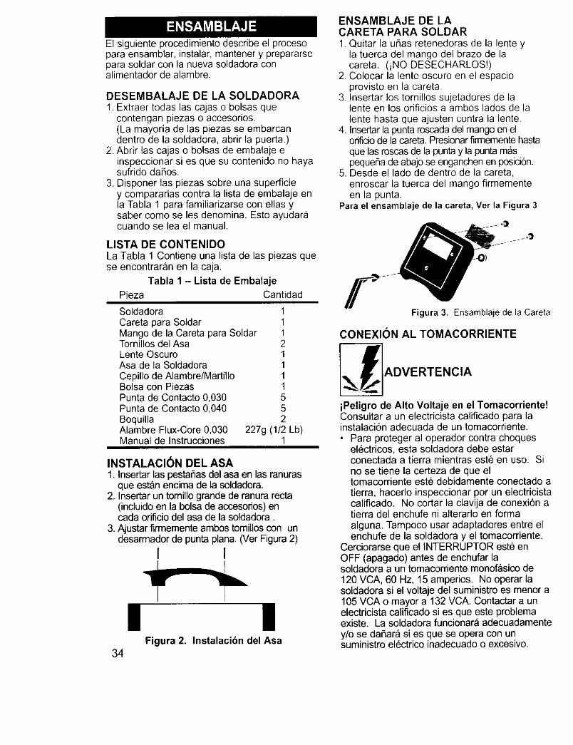
El siguiente procedimiento describe el procesopara ensamblar, instalar, mantener y prepararsepara soldar con la nueva soldadora conalimentador de alambre.
DESEMBALAJE DE LA SOLDADORA1. Extraer todas las cajas o bolsas que
contengan piezas o accesorios.(La mayoria de las piezas se embarcandentro de la soldadora, abrir la puerta.)
2. Abrir las cajas o bolsas de embalaje einspeccionar si es que su contenido no hayasufrido daflos.
3. Disponer las piezas sobre una superficiey compararlas contra la lista de embalaje enla Tabla 1 para familiarizarse con elias ysaber come se les denomina. Esto ayudaracuando se lea el manual.
LISTA DE CONTENIDOLa Tabla 1 Contiene una lista de las piezas quese encontraran en la caja.
Tabla 1 - Lista de EmbalajePieza Cantidad
Soldadora 1Careta para Soldar 1Mango de la Careta para Soldar 1Tornillos del Asa 2Lente Oscuro 1Asa de la Soldadora 1Cepillo de Alambre/Martillo 1Bolsa con Piezas 1Punta de Contacto 0,030 5Punta de Contacto 0,040 5Boquilla 2Alambre Flux-Core 0,030 227g (1/2Manual de Instrucciones 1
Lb)
INSTALACION DEL ASA1. Insertar las pestaSas del asa en las ranuras
que est_n encima de la soldadora.2. Insertar un tomillo grande de ranura recta
(incluido en la bolsa de accesorios) encada orificie del asa de la soldadora.
3. Ajustar firrnemente ambos tomillos con undesarmador de punta plan& (Ver Figura 2)
I 1
| |Figura 2. Instalacibn del Asa
34
ENSAMBLAJE DE LACARETA PARA SOLDAR1. Quitar la u_as retenedoras de la lente y
la tuerca del mango del braze de lacareta. (iNO DESECHARLOS!)
2. Colocar la lente oscuro en el espacioprovisto en la careta
3. Insertar los tornillos sujetadores de lalente en los orificios a ambos lades de lalente hasta que ajusten contra la lente.
4. Insertar la punta roscada del mango en elorificio de la careta. Presionar firmemente hastaque las roscas de la punta y la punta maspequeBa de abajo se enganchen en posici6n.
5. Desde el lade de dentro de la careta,enroscar la tuerca del mango firmementeen la punta.
Para el ensamblaje de la careta, Ver la Figura 3
Figura 3. Ensamblaje de la Careta
CONEXION AL TOMACORRIENTE
_],ADVERTENCIA
iPeligro de Alto Voltaje en el Tomacorriente!Consultar a un electricista calificado para lainstalaci6n adecuada de un tomacorriente.• Para proteger al operador contra cheques
electricos, esta soldadora debe estarconectada a tierra mientras este en use. Sino se tiene la certeza de que eltomacorriente este debidamente conectado atierra, hacerlo inspeccionar per un electricistacalificado. No cortar la clavija de conexi6n atierra del enchufe ni alterarlo en formaalguna. Tampoco usar adaptadores entre elenchufe de la soldadora y el tomacorriente.
Cerciorarse que el INTERRUPTER este enOFF (apagado) antes de enchufar lasoldadora a un tomacorriente monof_sico de120 VCA, 60 Hz, 15 amperios. No operar lasoldadora si el voltaje del suministro es menor a105 VCA o mayor a 132 VCA. Contactar a unelectricista calificado si es que este problemaexiste. La soldadora funcionara adecuadamentey/o se daflara si es que se opera con unsuministro electrico inadecuado o excesivo.
CORDONES DE EXTENSION
Para el rendimiento 6ptimo de la soldadora, no sedeben usar cordones de extensi6n a menos quesea absolutamente necesario. Si este fuese elcaso, tener cuidado de seleccionar el cord6n deextensi6n adecuado para la soldadora especificaen uso.
Seleccionar un cordon de extension que conectedebidamente a tierra directamente en eltomacorriente yen el enchufe de la soldadora sinusar adaptadores. Cerciorarse que el cordon deextension sea de los alambres adecuados y queeste en buenas condiciones electricas. Lasespecificaciones de los cordones de extensi6ndeben cumplir con las siguientes pautasgenerales:
• 0 a 7,6m / 25' requiere alambre calibre 12.• No usar cord6n de extension de mAs de
7,6m/25'.
SELECClON DEL ALAMBRESOLDADOR
Esta soldadora usa t_nicamente alambresoldador de nucleo fundente autoprotegido de0,8mm (0,030") o 0,9mm (0,035") en carretesde 10cm (4"). Con este alambre se puedesoldar acero desde calibre 18 (1,2mm) hastade 4,8mm (3/16") de espesor.NOTA:
Con esta soldadora no se debe soldar metalde un espesor menor a calibre 18. Si Iointenta Io atravesara perforando orificios enel metal.Si el alambre en el carrete estuviese muyoxidade, la Qnica seluci6n al problema esdesechar el carrete de alambre.
Si tiene un carrete con alambre oxidado, no Iodeseche hasta haber desenrollado unascuantas vueltas de alambre y ver si el alambreque esta mas adentro en el carrete esta encondiciones de usarse, de Io contrario,desechar el carrete.
INSTALACION DEL ALAMBRESOLDADOR
iLAS DESCARGAS ELIeCTRICAS PUEDENMATAR!Siempre apagar la soldadora poniendo elinterruptor en la posici6n "OFF" y desenchufardel tomacorriente antes de instalar el alambre.1. Sacar la boquilla y la punta de contacto
del extreme de la pistola soldadora.
2. Quitarle la tapa al eje.3. Desenrollar el alambre del carrete y encontrar
su extremo (pasa por el orificio en el bordeexterior del carrete y esta doblado para evitarque el alambre de desenrolle). PERO NODESENGANCHARLO AUN.
Forma incorrecta
Figura 4. InstalacionCorrecta del Alambre
4. Colocar el carrete en el eje de modo queel alambre al salir del carrete quede comeen la ilustraci6n superior en la Figura 4.Figura 4. Instalaci6n Correcta del Alambre
5. Insertar la ufia retenedora del carrete enel eje. La ufia se asegurara en posicionimpidiendo que el carrete se sueltedurante la operacion.
6. Colocar el extremo doblado del alambre conuna tenaza para que el extremo quede recto.
7. Sostener el brazo tensor arriba, alejado delpropulsor del carrete e insertar el extremodel alambre en la entrada del tube guia.Luego empujarlo pasando el rodillo deavarice y hasta que entre unos 15 cm. (6")en la pistola soldadora.
8. Alinear el alambre con la ranura exteriordel rodillo de avance y permitir que el brazetensor caiga sobre el rodillo de avance.
9. Regular la tensi6n girando el tornillo tensor(en el sentido del reloj) hasta que el rodillotensor aplique suficiente fuerza al alambrepara evitar que resbale fuera de la pistol&
10. Soltar el alambre11. Enchufar el cord6n de la soldadora al
tomacorriente. Colocar el selector decalor (HEAT) que esta en el frente de lasoldadora a cualquiera de las dosgraduaciones de temperatura.
_1_ ADVERTENCIA
Para reducir el riesgo per destellos del arco,asegurarse que al salir el alambre soldador de lapistol& no haga contacto con la pinza de
35
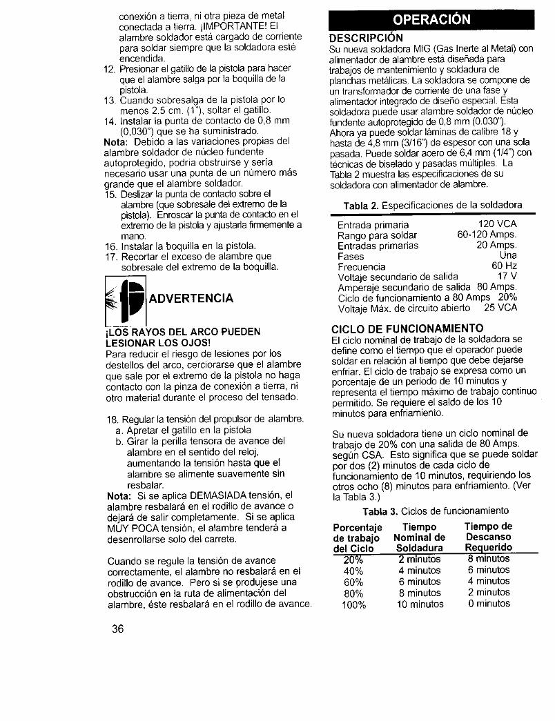
conexi6n a tierra, ni otra pieza de metalconectada a tierra, ilMPORTANTE! Elalambre soldador est& cargado de cordentepara soldar siempre que la soldadora est_encendida.
12. Presionar el gatillo de la pistola para hacerque el alambre salga per la boquilla de lapistola.
13. Cuando sobresalga de la pistola per Iomenos 2,5 cm. (1"), soltar el gatillo.
14. Instalar la punta de contacto de 0,8 mm(0,030") que se ha suministrado.
Nota: Debido alas variaciones propias delalambre soldador de nucleo fundenteautoprotegido, podria obstruirse y serianecesario usar una punta de un nOmero masgrande que el alambre soldador.15. Deslizar la punta de contacto sobre el
alambre (que sobresale del extreme de lapistola). Enroscar la punta de contacto en elextreme de la pistola y ajustada firmemente amane.
16. Instalar la boquilla en la pistola.17. Recortar el exceso de alambre que
sobresale del extreme de la boquilla.
gwi ADVERTENCIA
iLOS RAYOS DEL ARCO PUEDENLESIONAR LOS OJOS!Para reducir el riesgo de lesiones per losdestellos del arco, cerciorarse que el alambreque sale per el extreme de la pistola no hagacontacto con la pinza de conexi6n a tierra, niotro material durante el proceso del tensado.
18. Regular la tensi6n del propulsor de alambre.a. Apretar el gatillo en la pistolab. Girar la perilla tensora de avarice del
alambre en el sentido del reloj,aumentando la tensi6n hasta que elalambre se alimente suavemente sinresbalar.
Nota: Si se aplica DEMASIADAtensi6n, elalambre resbalara en el rodillo de avance odejara de salir completamente. Si se aplicaMUY POCA tensi6n, el alambre tender_ adesenrollarse solo del carrete.
Cuando se regule la tensi6n de avancecorrectamente, el alambre no resbatar_& en elrodillo de avance. Pero si se produjese unaobstrucci6n en la ruta de alimentacion delalambre, este resbalara en el rodillo de avarice.
36
DESCRIPCION
Su nueva soldadora MIG (Gas Inerte al Metal) conalimentador de alambre esta diseflada paratrabajos de mantenimiento y soldadura deplanchas metalicas. La soldadora se compone deun transformador de corriente de una fase yalimentador integrado de disefio especial. Estasoldadora puede usar alambre so/dador de nL_cleofundente autoprotegido de 0,8 mm (0.030").Ahora ya puede soldar laminas de calibre 18 yhasta de 4,8 mm (3/16") de espesor con una solapasada. Puede soldar acero de 6,4 mm (1/4") contecnicas de biselado y pasadas multiples. LaTabla 2 muestra las especificaciones de susoldadora con alimentador de alambre.
Tabla 2. Especificaciones de la soldadora
Entrada primaria 120 VCARange para soldar 60-120 Amps.Entradas primarias 20 Amps.Fases UnaFrecuencia 60 HzVoltaje secundario de salida 17 VAmperaje secundario de salida 80 Amps.Ciclo de funcionamiento a 80 Amps 20%Voltaje Max. de circuito abierto 25 VCA
CICLO DE FUNCIONAMIENTOEl ciclo nominal de trabajo de la soldadora sedefine come el tiempo que el operader puedesoldar en relaci6n al tiempo que debe dejarseenfriar. El cido de trabajo se expresa come unporcentaje de un periode de 10 minutes yrepresenta el tiempo m&ximo de trabajo continuepermitido, Se requiere el saldo de los 10minutes para enfriamiento.
Su nueva soldadora tiene un ciclo nominal detrabajo de 20% con una salida de 80 Amps.segQn CSA. Esto significa que se puede soldarper dos (2) minutes de cada ciclo defuncionamiento de 10 minutes, requiriendo losotros echo (8) minutes para enfriamiento. (Verla Tabla 3.)
Tabla 3. Ciclos de funcionamiento
Porcentaje Tiempo Tiempo dede trabajo Nominal de Descansodel Cicio Soldadura Requerido
20% 2 minutes 8 minutes40% 4 minutes 6 minutes60% 6 minutes 4 minutes80% 8 minutes 2 minutes
100% 10 minutes 0 minutes
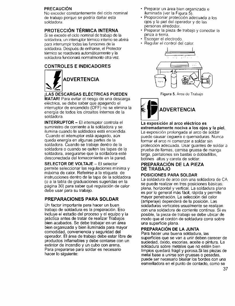
PRECAUCIONNoexcederconstantementedelciclonominalde trabajoporquese podriada_arestasoldadora
PROTECCION TI_RMICA INTERNASi se excede el ciclo nominal de trabajo de lasoldadora, un interruptor termico intemo se abrirapara interrumpir todas las funciones de lasoldadora Despues de enfriarse, el Protectortermico se reactivara automaticamente y lasoldadora funcionar& normalmente otra vez.
CONTROLES E INDICADORES
iLAS DESCARGAS ELI_CTRICAS PUEDENMATAR! Para evitar el riesgo de una descargaelectrica, se debe saber que apagando elinterruptor de encendido (OFF) no se elimina laenergia de todos los circuitos internos de lasoldadora.
INTERRUPTOR - El interruptor controla elsuministro de corriente a la soldadora y seilumina cuando la soldadora esta encendida.Cuando el interruptor est_ apagado, aOn
queda energ[a en algunas partes de lasoldadora. Cuando se trabaje dentro de lasoldadora o cuando se quiten las tapas de lasoldadora, asegurarse que la soldadora est6desconectada del tomacorriente en la pared.
SELECTOR DE VOLTAJE - El selectorpermite seleccionar las regulaciones minima ymaxima de calor. Referirse a la etiqueta deinstrucciones dentro de la tapa de la soldadora(o a la tabla de graduaciones sugeridas en lapagina 30) para saber que regulaci6n de calordebe usar para su trabajo.
PREPARACIONES PARA SOLDAR
Un factor importante para hacer un buentrabajo de soldadura es la preparaci6n. Esoincluye el estudio del proceso y el equipo y lapractica antes de tratar de realizar Trabajosbien acabados. Se debe trabajar en un areabien organizada y bien iluminada para mayorcomodidad, conveniencia y seguridad deloperador. El area de trabajo debe estar libre deproductos inflamables y debe contarse con unextintor de incendio y un cubo con arena.Para prepararse para soldar es necesariohacer Io siguiente:
• Preparar un area bien organizada eiluminada (ver la Figura 5).
• Proporcionar proteccion adecuada a losojos y la piel del operador y de laspersonas alrededor.
• Preparar la pieza de trabajo y conectar lapinza a tierra.
• Escoger el electrodo.• Regular el control del calor.
2 2 _
/
Figura 5. Area de Trabajo
!_p ADVERTENCIA
La exposicion al arco electrico esextremadamente nociva a los ojos y la piel.La exposici6n prolongada al arco de soldarpuede causar ceguera o quemaduras. Nuncaformar el arco ni comenzar a soldar sinproteccion adecuada. Usar guantes de soldar aprueba de llamas, camisa gruesa de mangalarga, pantalones sin bastas o dobladillos,botines altos y careta de soldar.PREPARACION DE LA PIEZADE TRABAJO
POSICIONES PARA SOLDARLa soldadura de arco con una soldadora de CAse puede realizar en tres posiciones basicas:plan& horizontal y vertical. La soldadura planaes por Io general mas facil, rapida y permitemayor penetraci6n. La selecci6n del calor(amperaje) dependera de la posici6n. Lassoldaduras verticales usualmente se realizancon una soldadora de corriente continua. Si esposible, la pieza de trabajo se debe ubicar demodo que el cord6n de soldadura corra sobreuna superficie plana.
PREPARACION DE LA JUNTAPara hacer una buena soldadura, lassuperficies que se van a unir deben carecer desuciedad, oxido, escorias, aceite o pintura. Lasoldadura sobre metales que no est6n bienlimpios quedara fragil y porosa.Si las piezas demetal base a unirse son gruesas o pesadas,puede ser necesario biselar los bordes con unaesmeriladora en el punto de contacto, como se
37
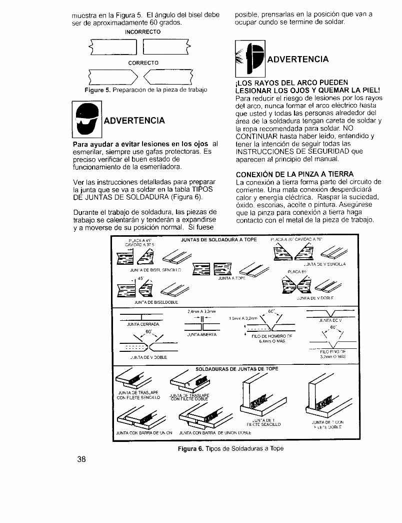
muestra en la Figura 5. El angulo del bisel debeset de aproximadamente 60 grados.
INCORRECTO
CORRECTO
>< IFigure 5. Preparaci6n de la pieza de trabajo
ADVERTENCIA
Para ayudar a evitar lesiones en los ojos alesmerilar, siempre use gafas protectoras. Espreciso verificar el buen estado defuncionamiento de la esmeriladora.
Ver las instrucciones detalladas para prepararla junta que se va a soldar en la tabla TIPOSDE JUNTAS DE SOLDADURA (Figura 6).
Durante el trabajo de soldadura, las piezas detrabajo se calentaran y tenderan a expandirsey a moverse de su posiciEn normal. Si fuese
posible, prensarlas en la posici6n que van aocupar cundo se termine de soldar.
iLOS RAYOS DEL ARCO PUEDENLESIONAR LOS OJOS Y QUEMAR LA PIEL!Para reducir el riesgo de lesiones por los rayosdel arco, nunca formar el arco electrico hastaque usted y todas las personas alrededor del_rea de la soldadura tengan careta de soldar yla ropa recomendada para soldar. NOCQNTINUAR hasta haber leido, entendido ytener la intencion de seguir todas lasINSTRUCCIONES DE SEGURIDAD queaparecen al principio del manual.
CONEXION DE LA PINZA A TIERRALa conexiEn a tierra forma parte del circuito decorriente. Una mala conexi6n desperdiciaracalory energia electrica. Raspar la suciedad,oxido, escorias, aceite o pintura. Asegt]reseque la pinza para conexion a tierra hagacontacto con el metal de la pieza de trabajo.
PLACA A 45
CAVIDAD A 37 5 _
JUNTA DE BISEL SENCILLO
JUNTA DE BISELDOBLE
JUNTAS DE SOLDADURA A TOPE PLACA A 60 CAVIDAD A 76
JUNTA DE V SENCILLA
PLACA 60
JUNTA DE V OOBLE
2,4mm A 32mm _ 60".,.,,.
I -I1- ,Er mA32,.m\ 7JUNTA I[
60"
_/ "-._j JUNTA ABIERTA _' FILO DE HOMBRO DE64mm O MAS
JUNTA DE V DOBLE
JUNTA DE v
60"
FILO FINO DE
32mm O MAS
SOLDADURAS DE JUNTAS DE TOPE
JUNTA DE TRASLAPEJ NTA D TRASLAPE
CON FILETE SENCILLO cUoN FII_TE OOBLE
_ JUNTA DE TFILETE SENCILLO
JUNTA CON BARRA DE UNION JUNTA CON BARRA DE UNION OOBLE
JUNTA DE T CON
FILETE DOBLE
38
Figura 6. Tipos de Soldaduras a Tope
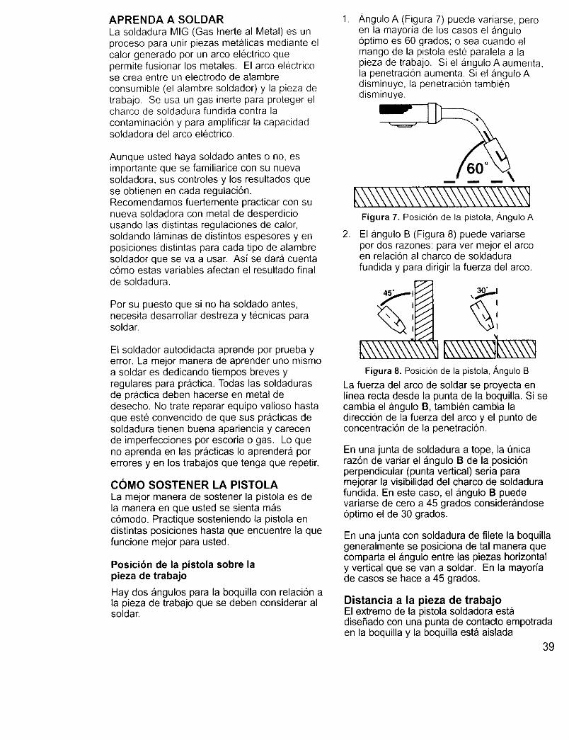
APRENDA A SOLDAR
La soldadura MIG (Gas Inerte al Metal) es unproceso para unir piezas metalicas mediante elcalor generado pot un arco electrico quepermite fusionar los metales. El arco electricose crea entre un electrodo de alambreconsumible (el alambre soldador) y la pieza detrabajo, Se usa un gas inerte para proteger elcharco de soldadura fundida contra la
contaminacion y para amplificar la capacidadsoldadora del arco electrico,
Aunque usted haya soldado antes o no, esimportante que se familiarice con su nuevasoldadora, sus controles y los resultados quese obtienen en cada regulaci6n.Recomendamos fuertemente practicar con sunueva soldadora con metal de desperdiciousando las distintas regulaciones de calor,soldando laminas de distintos espesores y enposiciones distintas para cada tipo de alambresoldador que se va a usar. Asi se dara cuentac6mo estas variables afectan el resultado finalde soldadura.
Per su puesto que si no ha soldado antes,necesita desarrollar destreza y tecnicas parasoldar.
El soldador autodidacta aprende por prueba yerror. La meier manera de aprender uno mismoa soldar es dedicando tiempos breves yregulares para practica. Todas las soldadurasde prg_ctica deben hacerse en metal dedesecho. No trate reparar equipo valioso hastaque este convencido de que sus practicas desoldadura tienen buena apariencia y carecende imperfecciones pot escoria o gas. Lo queno aprenda en las practicas Io aprendera porerrores yen los trabajos que tenga que repetir.
COMO SOSTENER LA PISTOLA
La mejor manera de sostener la pistola es dela manera en que usted se sienta masc6modo. Practique sosteniendo la pistola endistintas posiciones hasta que encuentre la quefuncione mejor para usted.
Posicibn de la pistola sobre lapieza de trabajo
Hay dos angulos para la boquilla con relacidn ala pieza de trabajo que se deben considerar alsoldar.
Angulo A (Figura 7) puede variarse, peroen la mayoria de los casos el angulooptimo es 60 grados; o sea cuando elmango de la pistola este paralela a lapieza de trabajo. Si el angulo A aumenta,la penetracion aumenta. Si el angulo Adisminuye, la penetracion tambicndisminuye.
Figura 7. Posicion de la pistola, ,&ngulo A
2. El angulo B (Figura 8) puede variarsepor dos razones: para ver mejor el arcoen relacion al charco de soldadurafundida y para dirigir la fuerza del arco.
Figura 8. Posicion de la pistol&/_ngulo B
La fuerza del arco de soldar se proyecta enlinea recta desde la punta de la boquilla. Si secambia el angulo B, tambien cambia ladireccion de la fuerza del arco y el punto deconcentraci6n de la penetraci6n.
En una junta de soldadura a tope, la t]nicaraz6n de variar el angulo B de la posici6nperpendicular (punta vertical) seria paramejorar la visibilidad del charco de soldadurafundida. En este caso, el angulo B puedevariarse de cero a 45 grados considerandoseoptimo el de 30 grados.
En una junta con soldadura de filete la boquillageneralmente se posiciona de tal manera quecomparta el angulo entre las piezas horizontaly vertical que se van a soldar. En la mayoriade casos se hace a 45 grados.
Distancia a la pieza de trabajoEl extremo de la pistola soldadora estadisefiado con una punta de contacto empotradaen la boquilla y la boquilla esta aislada
39
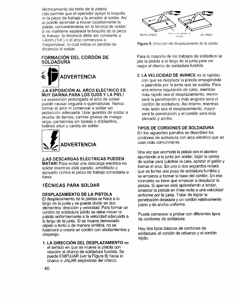
_lectricamentedelrestode lapistola.Estopermitequeeloperadorapoyelaboquilla_nla piezadetrabajoy laarrastreal soldar.Asi_epuedeaprendera moverestablementela_istola,concentrandoseen la tecaicadesoldar.Sise mantieneseparadalaboquillade lapiezaJetrabajo,ladistanciadebeserconstantea3,4mm(1/4")o el arcocomenzaraa:hisporrotear,Iocualindicaunperdidade_ficienciaal soldar.
FORMACION DEL CORDON DESOLDADURA
ADVERTENCIA
iLA EXPgSICION AL ARCO ELECTRICO ESMUY DANINA PARA LOS OJOS Y LA PIEL!La exposicion prolongada al arco de soldarpuede causar ceguera o quemaduras. Nuncaformar el arco ni comenzar a soldar sinproteccion adecuada. Usar guantes de soldar aprueba de llamas, camisa gruesa de mangalarga, pantalones sin bastas o dobladillos,botines altos y careta de soldar.
_] ADVERTENCIA
iLAS DESCARGAS EL#CTRICAS PUEDENMATAR! Para evitar una descarga electrica nosoldar mientras este parado, arrodillado oapoyado contra la pieza de trabajo conectada atierra.
TECNICAS PARA SOLDAR
DESPLAZAMIENTO DE LA PISTOLAEl desplazamiento de la pistola se hace a Iolargo de la junta y se puede dividir en doselementos: direcciOn y velocidad. Para formar uncordon de soldadura sOlido se debe mover lapistola uniformemente a la velocidad adecuada aIo largo de la junta. Si se mueve demasiadorapido o lento o de manera err_tica, no sefusionara o creara un cordon con abultamientos ydisparejo.
1. LA DIRECCION DEL DESPLAZAMIENTO esel sentido en que se mueve la pistola conrelacion al charco de soldadura fundida. Sepuede EMPUJAR (ver la Figura 9) hacia elcharco o JALAR alejandose del charco.
40
EMPUJANDO CIi.rr_ dl ",n_d_ldura JALANDOf_l_ldlda
Figura 9. Direccion del desplazamiento de la pistola
Para la mayoria de los trabajos de soldadura sejala la pistola a Io largo de la junta para vermejor el charco de soldadura fundida.
2. LA VELOClDAD DE AVANCE es la rapidezcon que se desplaza la pistola empujandolao jalandola por la junta que se suelda. Parauna misma regulaciOn de calor, mientrasmas rapido sea el desplazamiento, menorsera la penetraci6n y mas angosto sera elcordon de soldadura. Asi mismo, mientrasm_s lento sea el desplazamiento, mayorsera la penetracion y el cordon sera maselevado y ancho.
TIPOS DE CORDONES DE SOLDADURA
En los siguientes parrafos se describen loscordones de soldadura con arco elOctrico que seusan mas comunmente.
Una vez que acomode la pistola con el alambreapuntando a la junta por soldar, bajar la caretade soldar para cubrirse la cara, apretar el gatillo yformar el arco. En uno o dos segundos notaraque se forma una poza de soldadura fundida yse empieza a formar la base del cordon. En esemomento se tiene que empezar a desplazar lapistola. Si apenas esta aprendiendo a soldar,arrastrar la pistola en linea recta a una velocidaduniforme por la junta. Tratar de Iograr lapenetraciOn deseada y un cordon relativamentepiano y de ancho uniforme.
Puede comenzar a probar con diferentes tiposde cordones de soldadura.
Hay dos tipos basicos de cordones desoldadura, el cordon de refuerzo y el cordontejido.
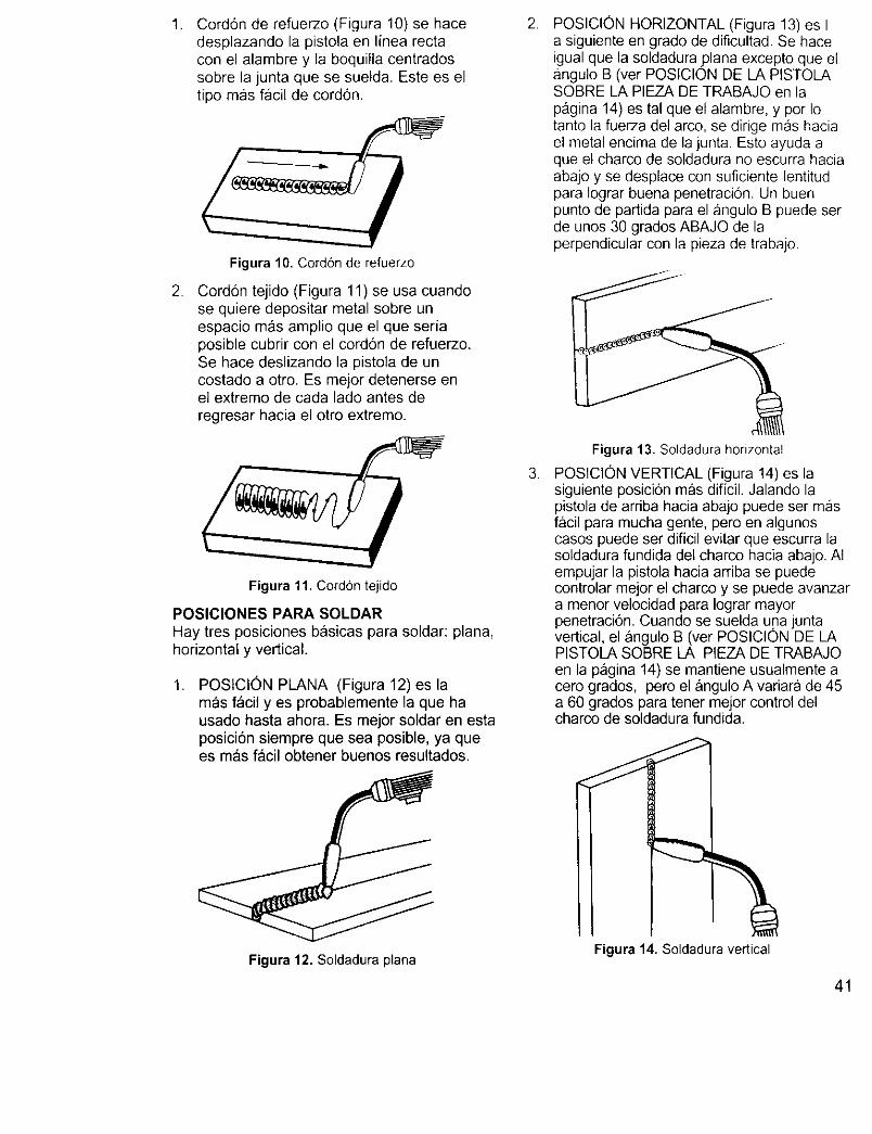
. Cord6n de refuerzo (Figura 10) se hacedesplazando la pistola en linea rectacon el alambre y la boquilla centradossobre la junta que se suelda. Este es eltipo mas facil de cord6n.
Figura 10. Cord6n de refuerzo
. Cordon tejido (Figura 11) se usa cuandose quiere depositar metal sobre unespacio mas amplio que el que seriaposible cubrir con el cordon de refuerzo.Se hace deslizando la pistola de uncostado a otro. Es mejor detenerse enel extremo de cada lado antes deregresar hacia el otro extremo.
Figura 11. CordOn tejido
POSIClONES PARA SOLDAR
Hay tres posiciones basicas para soldar: plana,horizontal y vertical.
, POSlCION PLANA (Figura 12) es lamas f_cil yes probablemente la que hausado hasta ahora. Es mejor soldar en estaposici6n siempre que sea posible, ya quees m&s facil obtener buenos resultados.
Figura 12. Soldadura plana
.
.
POSICION HORIZONTAL (Figura 13) es Ia siguiente en grado de dificultad. Se haceigual que la soldadura ?lana excepto que elangulo B (ver POSIClON DE LA PISTOLASOBRE LA PIEZA DE TRABAJO en lapagina 14) es tal que el alambre, y por Iotanto la fueFza del arco, se dirige mas haciael metal encima de la junta. Esto ayuda aque el charco de soldadura no escurra haciaabajo y se desplace con suficiente lentitudpara Iograr buena penetracion. Un buenpunto de partida para el angulo B puede serde unos 30 grados ABAJO de laperpendicular con la pieza de trabajo.
Figura 13. Soldadura horizontal
POSICION VERTICAL (Figura 14) es lasiguiente posicion mas dificil. Jalando lapistola de arriba hacia abajo puede ser masf&cil para mucha gente, pero en algunoscasos puede set dificil evitar que escurra lasoldadura fundida del charco hacia abajo. AIempujar la pistoia hacia arriba se puedecontrolar mejor el charco y se puede avanzara menor velocidad para Iograr mayorpenetraci6n. Cuando se suelda una juntavertical, el angulo B (ver POSICION DE LAPISTOLA SOBRE LA PIEZA DE TRABAJOen la pagina 14) se mantiene usualmente acero grados, pero el angulo A variara de 45a 60 grados para tener mejor control delcharco de soldadura fundida.
Figura 14. Soldadura vertical
41
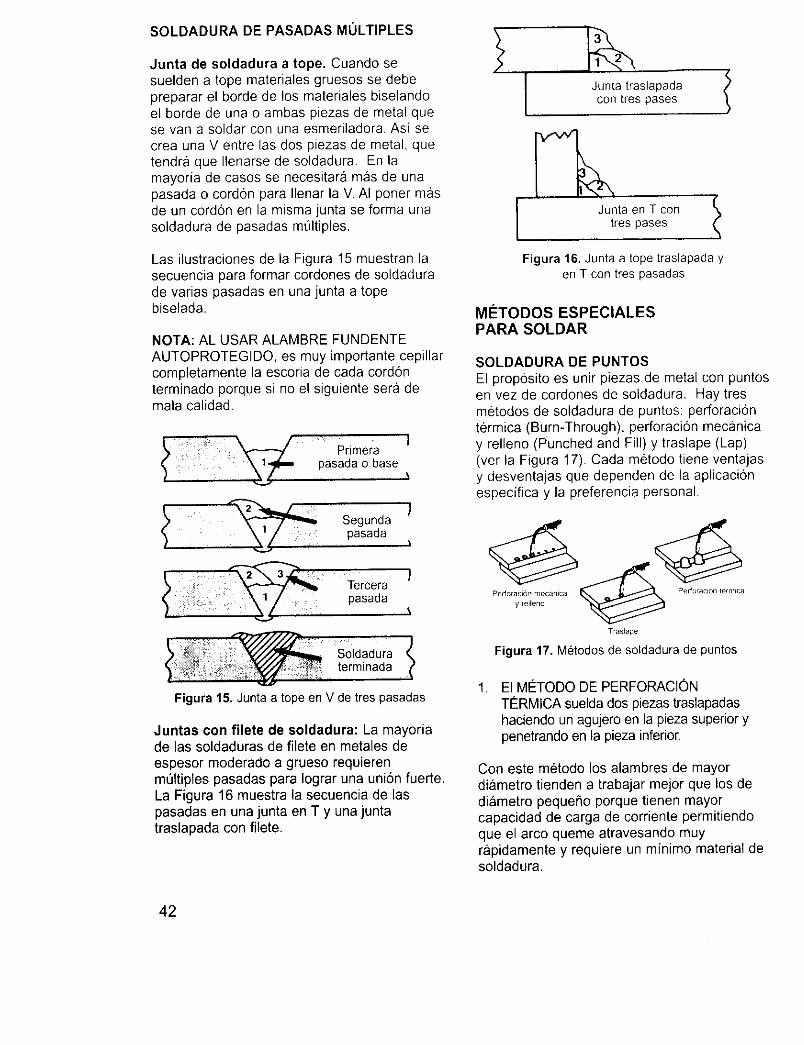
SOLDADURA DE PASADAS MULTIPLES
Junta de soldadura a tope. Cuando sesuelden a tope materiales gruesos se debepreparar el borde de los materiales biselandoel borde de una o ambas piezas de metal quese van a soldar con una esmeriladora. Asi secrea una V entre las dos piezas de metal, quetendra que Ilenarse de soldadura. En lamayoria de casos se necesitara mas de unapasada o cord6n para Ilenar la V. AI poner masde un cord6n en la mismajunta se forma unasoldadura de pasadas mt_ltiples.
Las ilustraciones de la Figura 15 muestran lasecuencia para formar cordones de soldadurade varias pasadas en una junta a topebiselada.
NOTA: AL USAR ALAMBRE FUNDENTEAUTOPROTEGIDO, es muy importante cepillarcompletamente la escoria de cada cordonterminado porque si no el siguiente sera demala calidad.
: Primerapasada o base
_ Segundapasada
I
\
!
Tercera Jpasada
\
Figura 15. Junta a tope en V de tres pasadas
Juntas con filete de soldadura: La mayoriade ias soldaduras de filete en metales deespesor moderado a grueso requierenmt_ltiples pasadas para Iograr una uni6n fuerteLa Figura 16 muestra la secuencia de laspasadas en una junta en T y una juntatraslapada con filete.
Junta traslapada /con tres pases
I Junta en T con
tres pases
Figura 16. Junta a tope traslapada yen T con tres pasadas
METODOS ESPECIALESPARA SOLDAR
SOLDADURA DE PUNTOSEl prop6sito es unir piezas de metal con puntosen vez de cordones de soldadura. Hay tresmetodos de soldadura de puntos: perforaci6ntermica (Burn-Through), perforaci6n mec&nicay relleno (Punched and Fill) y traslape (Lap)(ver la Figura 17). Cada metodo tiene ventajasy desventajas que dependen de la aplicaci6nespecifica y la preferencia personal.
Per f °ray'6ele'_n_°ecanica _ Perf°racl6£ 'e ......
Traslape
Figura 17. Metodos de soldadura de puntos
. El MC:TODO DE PERFORACIONTERMICA suelda dos piezas traslapadashaciendo un agujero en la pieza superior ypenetrando en la pieza inferior.
Con este metodo los alambres de mayordiametro tienden a trabajar mejor que los dediametro pequefio porque tienen mayorcapacidad de carga de corriente permitiendoque el arco queme atravesando muyrapidamente y requiere un minimo material desoldadura.
42

No se debe usar alambre de 0,80mm (0.030")de n0cleo fundente autoprotegido en el metodode perforacion termica, a menos que el metalsea MUY delgado o acepte una acumulacionexcesiva de material de soldadura conpenetracion minima.
Siempre seleccionar la regulacion ALTA de calorantes de soldar con este metodo y afinar lavelocidad del alambre antes de soldar porpuntos.
2. El MC:TODO DE PERFORACl0NMEC,g,NICA Y RELLENO produce lasoldadura de mejor acabado de estostres metodos. En este metodo se haceun agujero con un troquel o taladro en lapieza superior y se dirige el arco parapenetrar por este agujero hasta la piezainferior. Se deja que el metal fundidoIlene el agujero dejando un punto liso yraso en la superficie de la pieza superior.
Seleccionar el diametro del alambre, laregulaci6n de calory afinar la velocidaddel alambre como si se fuera a soldarmaterial del mismo espesor con uncord6n continuo.
3. En el MI_TODO DE SOLDADURA DEPUNTOS EN JUNTA TRASLAPADA sedirige el arco para que penetre laspiezas superior e inferior a la misma veza cada lado del traslape.
Seleccionar el diametro del alambre, laregulaci6n de calory afinar la velocidadcomo si se fuera a soldar material delmismo espesor con un cord6n continuo.
INSTRUCCIONES PARASOLDADURADE PUNTOS
1. Seleccionar el diametro del alambre y laregulaci6n de calor recomendadaantedormente para el metodo de soldadura porpuntos que se va a usar.2. Afinar la velocidad el alambre como si se fuesea hacer un cord6n continuo de soldadura.
3. Sostener la boquilla completamenteperpendicular a la pieza de trabajo, a unadistancia de 6,4ram (1/4").
4. Apretar el gatillo y soltado cuando se Iogre lapenetraci6n deseada.
5. Hacer puntos de soldadura de practica en metalde desecho, vadando el tiempo que aprieta elgatillo, hasta Iograr el punto de soldaduradeseado.
6. Hacer los puntos de soldadura en lasposiciones deseadas en las piezas de trabajo.
MANTENIMIENTO GENERALEsta soldadora esta disefiada para ofrecermuchos afios de servicio sin problemas siempre ycuando se sigan unos pasos sencillos demantenimiento.
1. Mantener cerrada la tapa del compartimientodel alambre en todo momento a menos quetenga que cambiar el alambre o regular latension del alambre.
.
,
4.
Conservar limpios todos los materialesconsumibles (puntas de contacto y boquillas) ycambiarlas cuando sea necesario. Si deseainformaci6n detallada, referirse a la secci6n deMANTENIMIENTO Y LIMPIEZA mas adelanteen esta seccion.
Reemplazar el cable de suministro, el cable deconexi6n y la pinza de conexion a tierra o lapistola cuando se noten daBos o desgaste.
Limpiar peri6dicamente el polvo, la suciedad,la grasa, etc. de su soldadora. Cada seismeses o cuando sea necesario, quitar lascubiertas laterales de la soldadora y sopletearcon aire a presi6n la suciedad acumuladadentro de la soldadora.
iLAS DESCARGAS EL#CTRICAS PUEDENMATAR! Para reducir el riesgo de descargaelectrica, siempre desconectar la soldadora deltomacorriente (CA) antes de quitar lascubiertas laterales.
MANTENIMIENTO DE INSUMOSEL MANTENIMIENTO DE LOS ARTiCULOSDE CONSUMO ES MUY IMPORTANTE PARAEVITAR EL REEMPLAZO PREMATURO DE LAPISTOLA SOLDADORA.
MANTENIMIENTO DE LA PUNTA DECONTACTOEl prop6sito de la punta de contacto es transferir lacorriente de la soldadura al alambre soldador a lavez que permitir que el alambre pase suavemente.
Siempre usar una punta de contacto estampadacon el mismo di&metro que el alambre que seusar&
Nota: Debido alas variaciones propias delalambre soldador de nQcleo fundenteautoprotegido, podria obstruirse y seria necesariousar una punta de un nt)mero m&s grande que elalambre soldador.
43
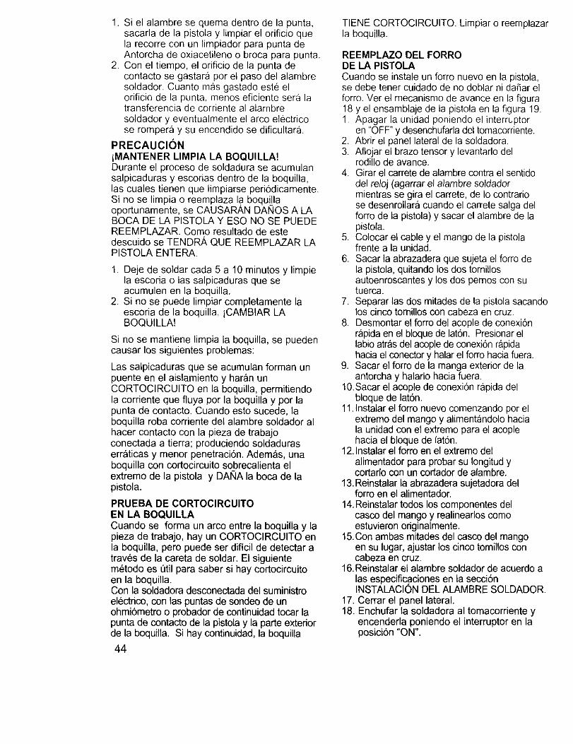
1. Si el alambre se quema dentro de la punta,sacarla de la pistola y limpiar el orificio quela recorre con un limpiador para punta deAntorcha de oxiacetileno o broca para punta.
2. Con el tiempo, el orificio de la punta decontacto se gastara per el paso del alambresoldador. Cuanto mas gastado este elorificio de la punta, menos eficiente sera latransferencia de corriente al alambresoldador y eventualmente el arco electricose rompera y su encendido se dificultara.
PRECAUCION
iMANTENER LIMPIA LA BOQUILLA!Durante el proceso de soldadura se acumulansalpicaduras y escorias dentro de la boquilla,las cuales tienen que limpiarse periodicamente.Si no se limpia o reemplaza la boquillaoportunamente, se CAUSARAN DANES A LABOCA DE LA PISTOLA Y ESO NQ SE PUEDEREEMPLAZAR. Come resultado de estedescuido se TENDR, _, QUE REEMPLAZAR LAPISTOLA ENTERA.
1. Deje de soldar cada 5 a 10 minutes y limpiela escoria o las salpicaduras que seacumulen en la boquilla.
2. Si no se puede limpiar completamente laescoria de la boquilla, iCAMBIAR LABOQUILLA!
Si no se mantiene limpia la boquilla, se puedencausar los siguientes problemas:
Las salpicaduras que se acumulan forman unpuente en el aislamiento y haran unCORTOCIRCUITO en la boquilla, permitiendola corriente que fluya per la boquilla y per lapunta de contacto. Cuando esto sucede, laboquilla roba corriente del alambre soldador alhacer contacto con la pieza de trabajoconectada a tierra; produciendo soldaduraserraticas y menor penetraci6n. Ademas, unaboquilla con cortocircuito sobrecalienta elextreme de la pistola y DANA la boca de lapistola.
PRUEBA DE CORTOCIRCUITOEN LA BOQUILLA
Cuando se forma un arco entre la boquilla y lapieza de trabajo, hay un CORTOCIRCUITO enla boquilla, pero puede ser dificil de detectar atrav6s de la careta de soldar. El siguientem_todo es =3tilpara saber si hay cortocircuitoen la boquilla.Con la soldadora desconectada del suministroelectdco, con las puntas de sondeo de unohmi6metro o probador de continuidad tocar lapunta de contacto de la pistola y la parte exteriorde la boquilla. Si hay continuidad, la boquilla
44
TIENE CORTOCIRCUITO. Limpiar o reemplazarla boquilla.
REEMPLAZO DEL FORRODE LA PISTOLACuando se instale un forro nuevo en la pistola,se debe tener cuidado de no doblar ni da_ar elferro. Ver el mecanismo de avance en la figura18 y el ensamblaje de la pistola en la figura 19.1. Apagar la unidad poniendo el interrupter
en "OFF" y desenchufarla del tomacorriente.2. Abrir el panel lateral de la seldaclera.3. Aflojar el braze tensor y levantarlo del
rodillo de avance.4. Girar el carrete de alambre contra el sentido
del reloj (agarrar el alambre soldadormientras se gira el carrete, de Io contrariose desenrollara cuando el carrete salga delforre de la pistola) y sacar el alambre de lapistola.
5. Colocar el cable y el mango de la pistolafrente a la unidad.
6. Sacar la abrazadera que sujeta el forro dela pistola, quitando los dos tornillosautoenroscantes y los dos pernos con sutuerca.
7. Separar las dos mitades de la pistola sacandolos cinco tomillos con cabeza en cruz.
8. Desmontar el forro del acople de conexi6nrapida en el bloque de lat6n. Presionar ellabio atr_s del acople de conexi6n rapidahacia el conector y halar el forro hacia fuera.
9. Sacar el forte de la manga exterior de laantorcha y halarlo hacia fuera.
t 0. Sacar el acople de conexi6n rapida delbloque de lat6n.
11. Instalar el forro nuevo comenzando per elextreme del mango y alimentandolo haciala unidad con el extreme para el acoplehacia el bloque de laton.
12. Instalar el forro en el extreme delalimentador para probar su Iongitud ycortarlo con un cortador de alambre.
13. Reinstalar la abrazadera sujetadora delforte en el alimentador.
14. Reinstalar todos los componentes delcasco del mango y realinearlos comeestuvieron originalmente.
15. Con ambas mitades del casco del mangoen su lugar, ajustar los cinco tornillos concabeza en cruz.
16. Reinstalar el alambre soldador de acuerdo alas especificaciones en la secci6nINSTALACION DEL ALAMBRE SOLDADOR.
17. Cerrar el panel lateral.18. Enchufar la soldadora al tomacorriente y
encenderla poniendo el interrupter en laposici6n "ON".
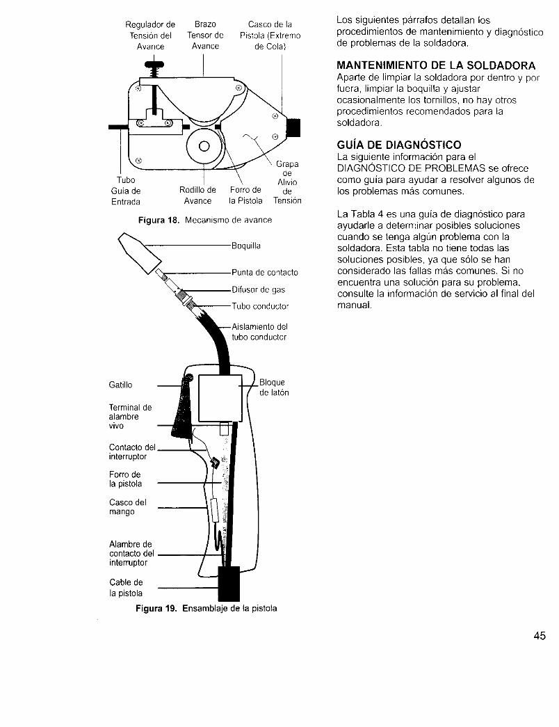
Regulador de Brazo Casco de laTensiondel Tensor de Pistola (Extremo
Avance Avance de Cola)
®pa
deTubo Alivio
Guia de Rodillo de Forro de de
Entrada Avance la Pistola Tension
Figura 18. Mecanismo de avance
Boquilla
Punta de contacto
Difusor de gas
conductor
deltubo conductor
Los siguientes parrafos detallan losprocedimientos de mantenimiento y diagn6sticode problemas de la soldadora.
MANTENIMIENTO DE LA SOLDADORA
Aparte de limpiar la soldadora por dentro y porfuera, limpiar la boquilla y ajustarocasionalmente los tornillos, no hay otrosprocedimientos recomendados para lasoldadora.
GUJA DE DIAGNOSTICO
La siguiente informacion para elDIAGNOSTICQ DE PROBLEMAS se ofrece
como guia para ayudar a resolver algunos delos problemas mas comunes.
La Tabla 4 es una guia de diagnostico paraayudarle a determinar posibles solucionescuando se tenga algOn problema con lasoldadora. Esta tabla no tiene todas las
soluciones posibles, ya que s61o se hanconsiderado las fallas mas comunes. Si no
encuentra una solucion para su problema,consulte la informaci6n de servicio al final delmanual.
Gatillo . Bloquede lat6n
Terminaldealambrevivo
Contacto del__interruptor
Forro dela pistola
Casco delmango
Alambre decontacto delinterruptor
Cable dela pistola
Figura 19. Ensamblaje de la pistola
45
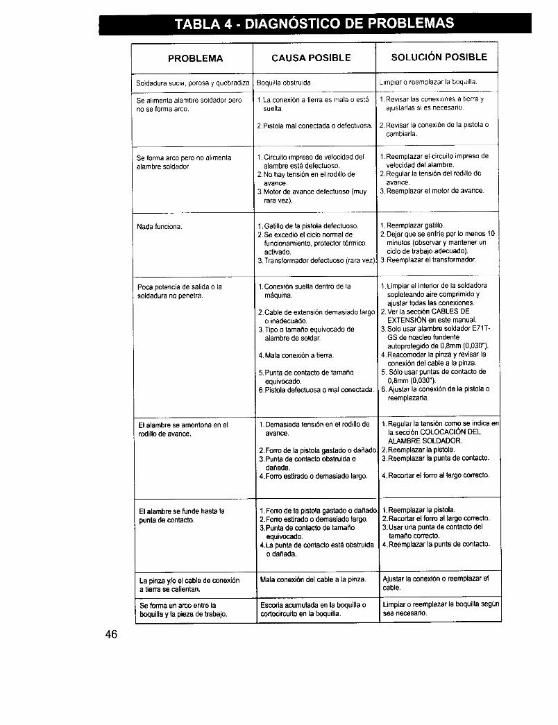
PROBLEMA
Soldadura sucia, porosa y quebradiza
Se alimenta alambre soldador perono se forma arco.
Se forma arco pero no alimentaalambre soldador
Nada funciona.
Poca potencia de salida o lasoldadura no penetra.
El alambre se amontona en elrodillo de avanco,
CAUSA POSIBLE
Boqui!la obstruida
1La conexi6n a tierra es mala o estasuelta
2.Pistola real conectada o defectuosa.
1. Circuito impreso de velocidad delalambre est_ defectuoso.
2No hay tensi6n en el rodillo deavarice
3. Motor de avanca defectuoso (muyrara vez).
1,Gatillo de la pistola defectuoso.2, Se excedio el ciclo normal de
funcionamiento, protector t6rmicoactivado.
3 Transformador defectuoso (rara vez)
1,Conexi6n suelta dentro de la
m_quina.
2 Cable de extensibn demasiado largoo inadecuado.
i 3 Tipo o tamafio equivocado dealambre de soldar
4. Mala conexi6n a tierra.
5.Punta de contacto de tamafioequivocado,
6.Pistola defectuosa o mal conectada,
1. Demasiada tensi6n en el rodillo de
avaRce.
SOLUCION POSIBLE
Limpiar o reemplazar la boquilla
1 Revisar las conexiones a tierra yajustarlas sqes necesario
2. Revisar la conexide de la pistola ocambiarla
1. Reemplazar et circuito impresodevelocidad del alambre.
2. Regular la tensibn del rodillo deavarice.
3. Reemplazar el motor de avance
!. Reemplazar gatillo2 Dejar que se enfrie por Io menos 10
minutos (observar y mantener uncielo de trabajo adecuado).
3 Reemplazar el transformador.
1 Limpiar el interior de Is soldadorasopleteando aire comprimido yajustar todas las conexiones.
2 Vet la seccion CABLES DEEXTENSION en este manual,
3 Solo usar alambre soldador E71T-GS de noeeleo fundenteautoprotegido de 0,8mm (0,030").
4.Reacomodar la pinza y revisar laconexi6n del cable a la pinza.
5. $61o usar puntas de contacto de0,Smm (0,030").
6 AJustar la conexi6n de la pistola oreemplazarla
1.Regular la tension come se indica erla secci6n COLOCAClON DELALAMBRE SOLDADOR,
2.Reemplazar la pistola.3.Reemplazar la punta de contacto.
2.Forro de la pistola gastado o daflado.3,Punta de contacto obstruidao
daflada.4.Forro estirado o demasiado largo. 4, Recortar el forro al largo correcto.
El alambre se funde hasta la 1.Forro de la pistola gastado o dafiado 1.Reem plazar la pistola.
punta de contacto. 2.Form estirado o demasiado largo. 2.Recortar el form al largocorrecto.3.Punta de contacto de tamafio 3.Usar una punta de contacto del
equivocado. LamafiocorTecto.4.La punta de contacto est_ obstruida 4.Reemplazar la punta de contacto.
o dafiada.
La pinza y/o el cable de conexi6n Mala conexibn del cable a la pinza. Ajustar la conexi6n o reempl_zar ela tierra se calientan, cable.
, Se forma un arco entre Is Escoda acumulada en la boqeilla o Limpiar o reemplazar la boquilla seg0=
boquilla y la pieza de trabajo, cortocircuito en la boquilla, sea necosario.
46
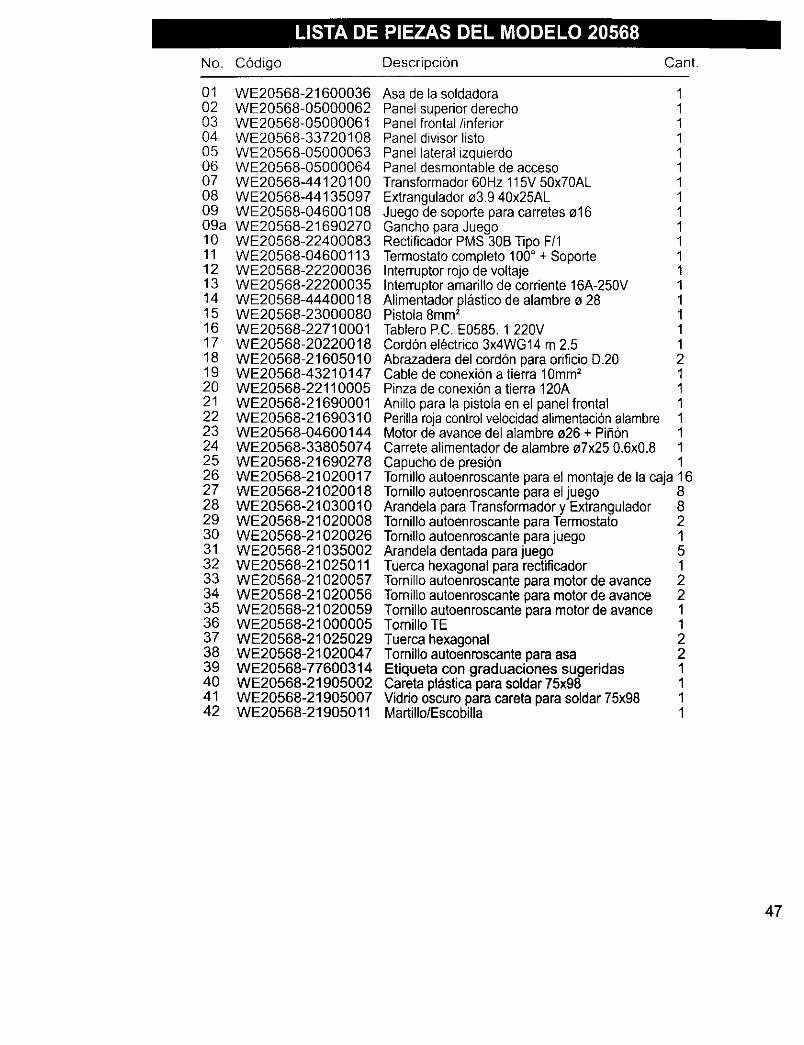
No. C6digo Descripci6n Cant.
01 WE20568-2160003602 WE20568-0500006203 WE20568-0500006104 WE20568-3372010805 WE20568-0500006306 WE20568-0500006407 WE20568-4412010008 WE20568-4413509709 WE20568-0460010809a WE20568-2169027010 WE20568-2240008311 WE20568-0460011312 WE20568-2220003613 WE20568-2220003514 WE20568-444000t815 WE20568-2300008016 WE20568-2271000117 WE20568-2022001818 WE20568-2160501019 WE20568-4321014720 WE20568-2211000521 WE20568-2169000122 WE20568-2169031023 WE20568-0460014424 WE20568-3380507425 WE20568-2169027826 WE20568-2102001727 WE20568-2102001828 WE20568-2103001029 WE20568-2102000830 WE20568-2102002631 WE20568-2103500232 WE20568-2102501133 WE20568-2102005734 WE20568-2102005635 WE20568-2102005936 WE20568-2100000537 WE20568-2102502938 WE20568-2102004739 WE20568-7760031440 WE20568-2190500241 WE20568-2190500742 WE20568-21905011
Asa de la soldadora 1Panel superior derecho 1Panel frontal/inferior 1Panel divisor listo 1Panel lateral izquierdo 1Panel desmontable de acceso 1Transformador 60Hz 115V 50x70AL 1Extrangulador o3.9 40x25AL 1Juego de soporte para carretes o16 1Gancho para Juego 1Rectificador PMS 30B Tipo F/1 1Termostato completo 100° + Soporte 1Interruptor rojo de voltaje 1Interruptor amarillo de corriente 16A-250V 1Alimentador plastico de alambre o 28 1Pistola 8mm2 1Tablero EC. E0585. 1 220V 1Cord6n electrico 3x4WG 14 m 2.5 1Abrazadera del cord6n para orificio D.20 2Cable de conexi6n a tierra 10mm 2 1Pinza de conexi6n a tierra 120A 1Anillo para la pistola en el panel frontal 1Perilla roja control velocidad alimentaci6n alambre 1Motor de avance del alambre o26 + Pifi6n 1Carrete alimentador de alambre o7x25 0.6x0.8 1Capucho de presi6n 1Tomillo autoenroscante para el montaje de la caja 16Tomillo autoenroscante para el juego 8Arandela para Transformador y Extrangulador 8Tornillo autoenroscante para Termostato 2Tornillo autoenroscante para juego 1Arandela dentada para juego 5Tuerca hexagonal para rectificador 1Tornillo autoenroscante para motor de avance 2Tornillo autoenroscante para motor de avance 2Tomillo autoenroscante para motor de avance 1Tomillo TE 1Tuerca hexagonal 2Tornillo autoenroscante para asa 2Etiqueta con graduaciones sugeridas 1Careta pl_stica para soldar 75x98 1Vidrio oscuro para careta para soldar 75x98 1Martillo/Escobilla 1
47
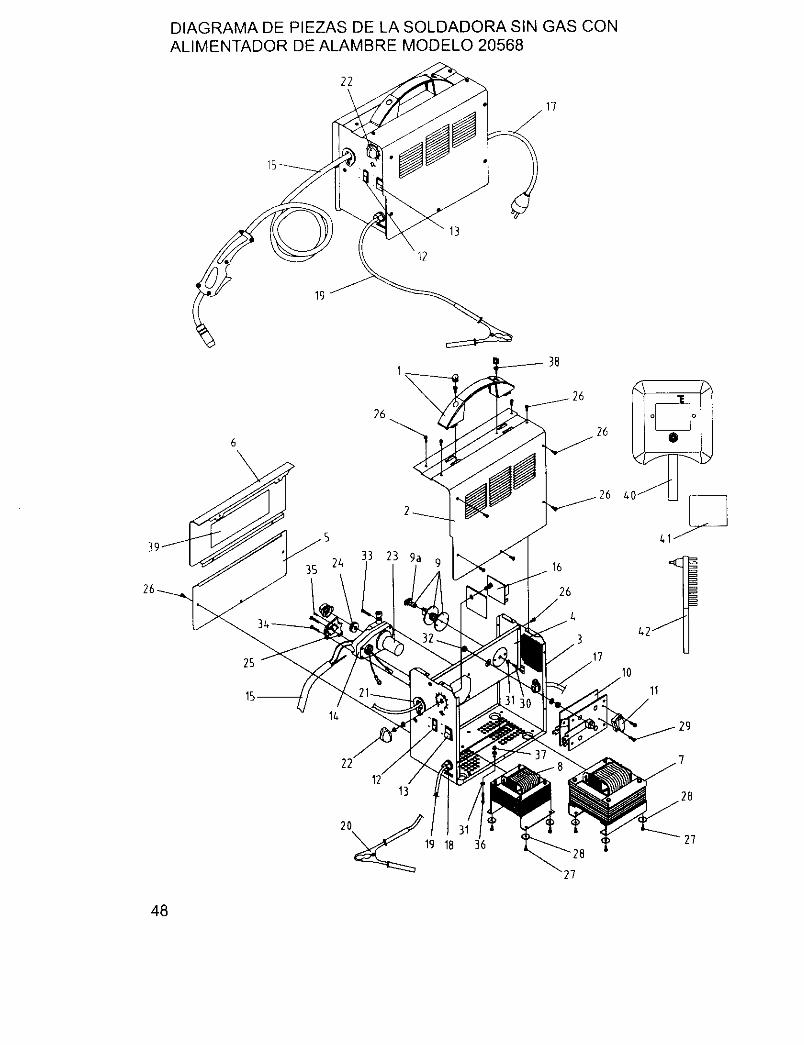
DIAGRAMADE PIEZAS DE LASOLDADORASIN GAS CONALIMENTADOR DE ALAMBRE MODELO 20568
22
13
12
6
\
25
26
33 23 ga35 16
26
11
13
20_19 1836
48
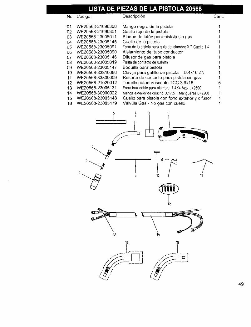
No. C6digo: Descripci6n Cant.
01 WE20568-2169030002 WE20568-2169030103 WE20568-2300501104 WE20568-2300514505 WE20568-2300509106 WE20568-2300509007 WE20568-2300514608 WE20568-2300501909 WE20568-2300514710 WE20568-3381009011 WE20568-3380000912 WE20568-2102001213 WE20568-2300513114 WE20568-3090002215 WE20568-2300514816 WE20568-23005179
Mango negro de la pistola 1Gatillo rojo de la pistola 1Bloque de lat6n para pistola sin gas 1Cuello de la pistola 1Forrode la pistolaparaguia delalambre XT Cuello 14 1Aislamiento del tubo conductor 1
Difusor de gas para pistola 1Puntade contactode 0,8ram 1Boquilla para pistola 1Clavija para gatillo de pistola D.4x16 ZN 1Resorte de contacto para pistola sin gas 1Tornillo autoenroscante TCC 3.9x16 5
Forroinoxidableparaalambre 1,4X4Azul L=2500 1Mangaexteriorde caucho D.17.5+ ManguerasL=2200 1Cuello para pistola con forro exterior y difusor 1Valvula Gas - No gas con cuello 1
10 2 11
÷12
16
i /S --''----J
*_.,g
15
49
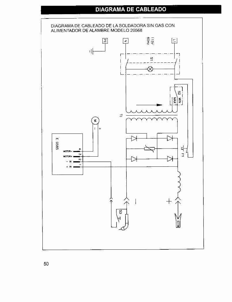
DIAGRAMA DE CABLEADO DE LA SOLDADORA SIN GAS CONALIMENTADOR DE ALAMBRE MODELO 20568
r'q
OO"IO_
Ido'IrOR-
MOTOR+
-IN
L
] [ I:>I-
Ii>l-
\ -I-
5O
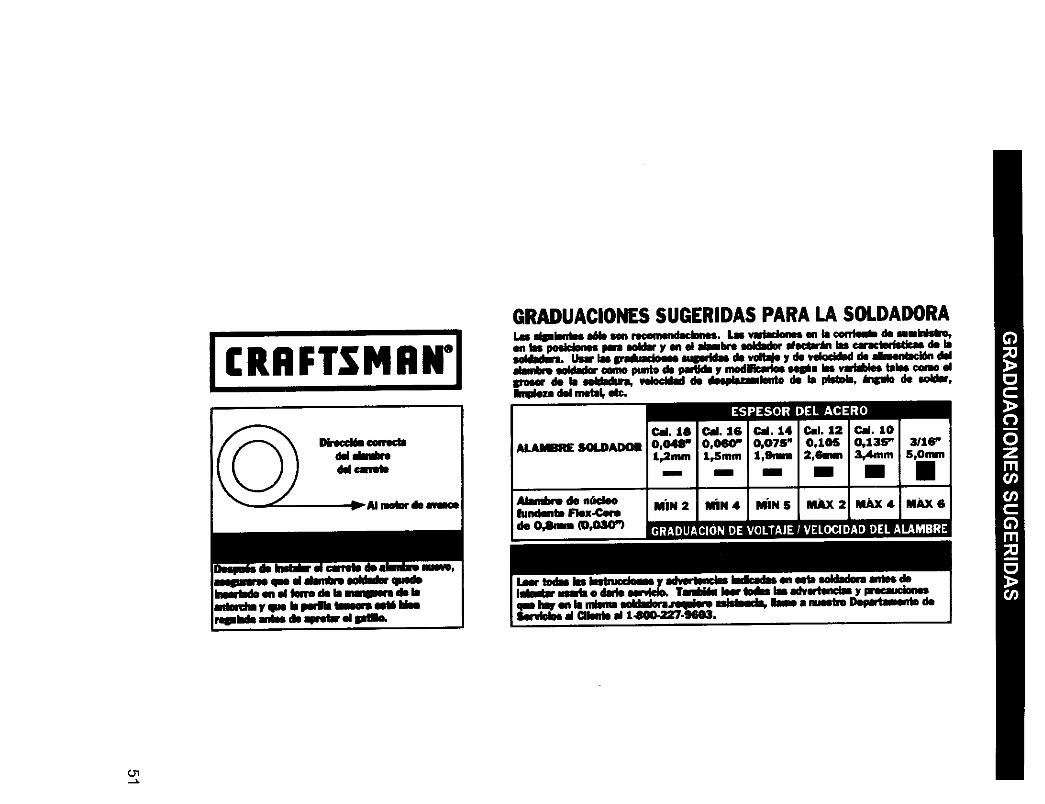
GRADUACIONESSUGERIDAS PARA LA SOLDADORAI._ slplen_ al441osm rl_nmMacl_. Ln vadadenesen la €on'lea_de umlnhdm,en lu posid_ im Nldar yen el alambremklader also,in lascaracterlstl_ de lasddlad_ Usarlasip.aduadom mqm.klasde vd_e y de vdocidmdde drmeedac_ ddalmnl_ wldador oonmpuntode padldoy modllk:adoes4_m ks vadaldestales€_ elm'mmrde b _4dadu.,, velocld_ddo abspb,mmlentode '., idstob, _mdo de .okbr,Iknude_dd me_l, etc.
Dk.eccimcew*oc_dd dadxedd cm'_te
w(mr diem
ALAMBRI£SOLDA.DOII

Get it fixed, at your home or ours!
Your Home
For repair-in your home- of all major brand appliances,lawn and garden equipment, or heating and cooling systems,
no matter who made it, no matter who sold it!
For the replacement parts, accessories and
owner's manuals that you need to do-it-yourself.
For Sears professional installation of home appliancesand items like garage door openers and water heaters.
1-800-4-MY-HOME ® Anytime, day or night
(1-800-469-4663) (U.S.A. and Canada)www.sears.com www.sears.ca
Our Home
For repair of carry-in products like vacuums, lawn equipment,and electronics, call or go on-line for the nearest
Sears Parts and Repair Center.
1-800-488-1222 Anytime, day or night (U.S.A. only)
www.sears.com
To purchase a protection agreement (U.S.A.)or maintenance agreement (Canada) on a product serviced by Sears:
1-800-827-6655 (u.s_.) 1-800-361-6665 (Canada)
Para pedir servicio de reparaci6na domicilio, y para ordenar piezas:
1-888-SU-HOGAR si(1-888-784-6427)
Au Canada pour service en franq, ais:
1-800-LE-FOYER Mc
(1-800-533-6937)www.sears.ca
8E/A/R6©S_r_ _and Co.
® Registered Trademark / TMTrademark / SMService Mark of Sears, Roebuck and Co.® Marca Registrada / TMMarca de F&brica / su Marca de Servicio de Sears, Roebuck and Co.MC MDMarque de commerce / Marque depos_e de Sears, Roebuck and Co.