Microprocessor-Based System. What is it? How simple can a microprocessor-based system actually be?...
20
Microprocessor-Based System
-
Upload
michael-henderson -
Category
Documents
-
view
225 -
download
0
Transcript of Microprocessor-Based System. What is it? How simple can a microprocessor-based system actually be?...
Microprocessor-Based System
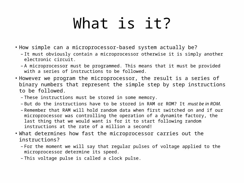
What is it?• How simple can a microprocessor-based system actually be?
– It must obviously contain a microprocessor otherwise it is simply another electronic circuit.
– A microprocessor must be programmed. This means that it must be provided with a series of instructions to be followed.
• However we program the microprocessor, the result is a series of binary numbers that represent the simple step by step instructions to be followed. – These instructions must be stored in some memory. – But do the instructions have to be stored in RAM or ROM? It must be in ROM.– Remember that RAM will hold random data when first switched on and if our
microprocessor was controlling the operation of a dynamite factory, the last thing that we would want is for it to start following random instructions at the rate of a million a second!
• What determines how fast the microprocessor carries out the instructions? – For the moment we will say that regular pulses of voltage applied to the microprocessor
determine its speed. – This voltage pulse is called a clock pulse.
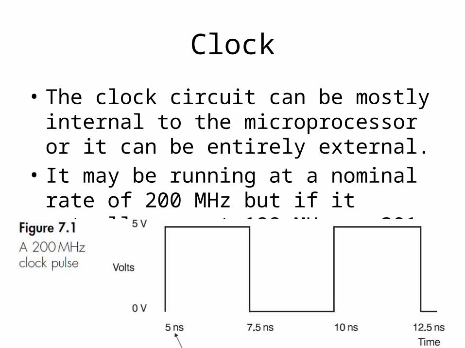
Clock
• The clock circuit can be mostly internal to the microprocessor or it can be entirely external.
• It may be running at a nominal rate of 200 MHz but if it actually ran at 199 MHz or 201 MHz there would be no great panic.
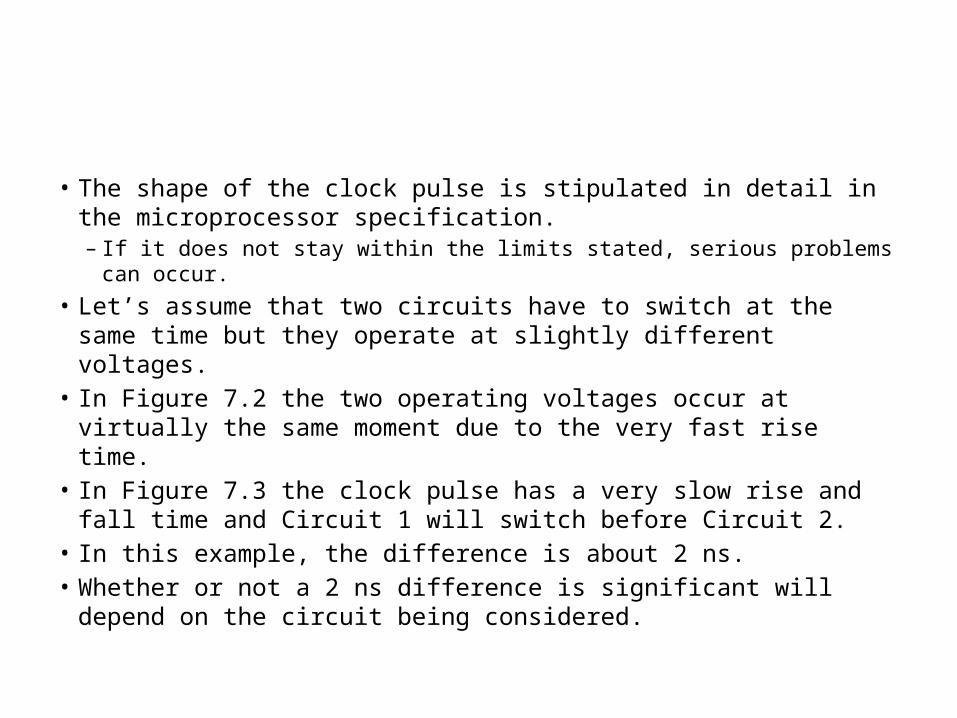
• The shape of the clock pulse is stipulated in detail in the microprocessor specification. – If it does not stay within the limits stated, serious problems can occur.
• Let’s assume that two circuits have to switch at the same time but they operate at slightly different voltages.
• In Figure 7.2 the two operating voltages occur at virtually the same moment due to the very fast rise time.
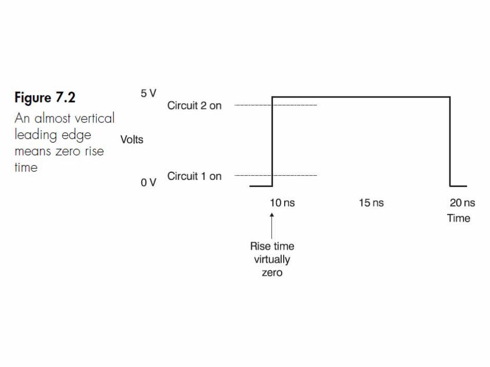
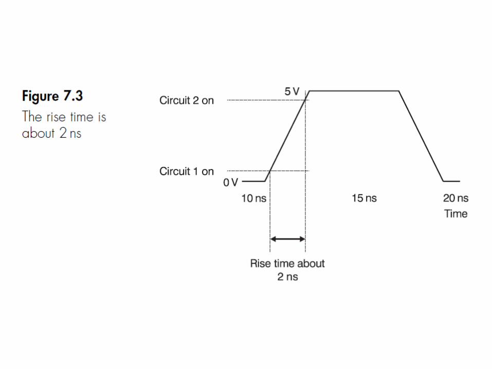
• In Figure 7.3 the clock pulse has a very slow rise and fall time and Circuit 1 will switch before Circuit 2.
• In this example, the difference is about 2 ns. • Whether or not a 2 ns difference is significant will depend on the
circuit being considered.

• All microprocessor technical data will stipulate the maximum rise time and fall time and between which voltages it is being measured.
• For example, the Intel 80386 has a supply voltage of 0–5 V and must have a rise time (and fall time) of less than 2 ns when measured between 0.8 V and 4.2V.
• If the rise time (written as tr or trise) is not shown, it is normally measured between 10 and 90% values of the supply voltage. Each microprocessor has a maximum frequency for the clock pulses and a minimum value.
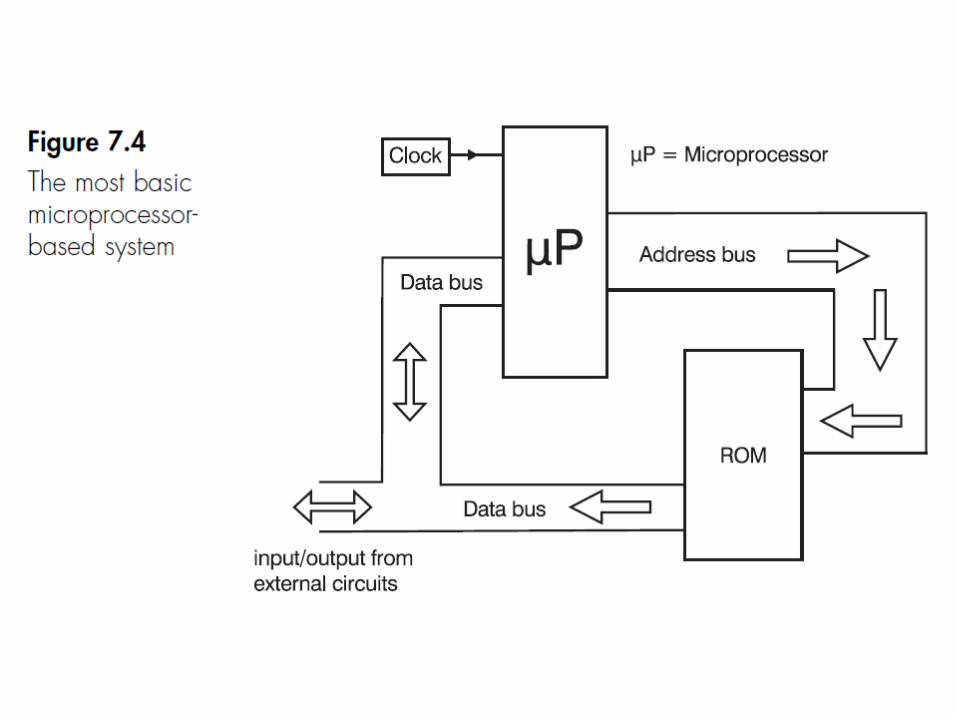

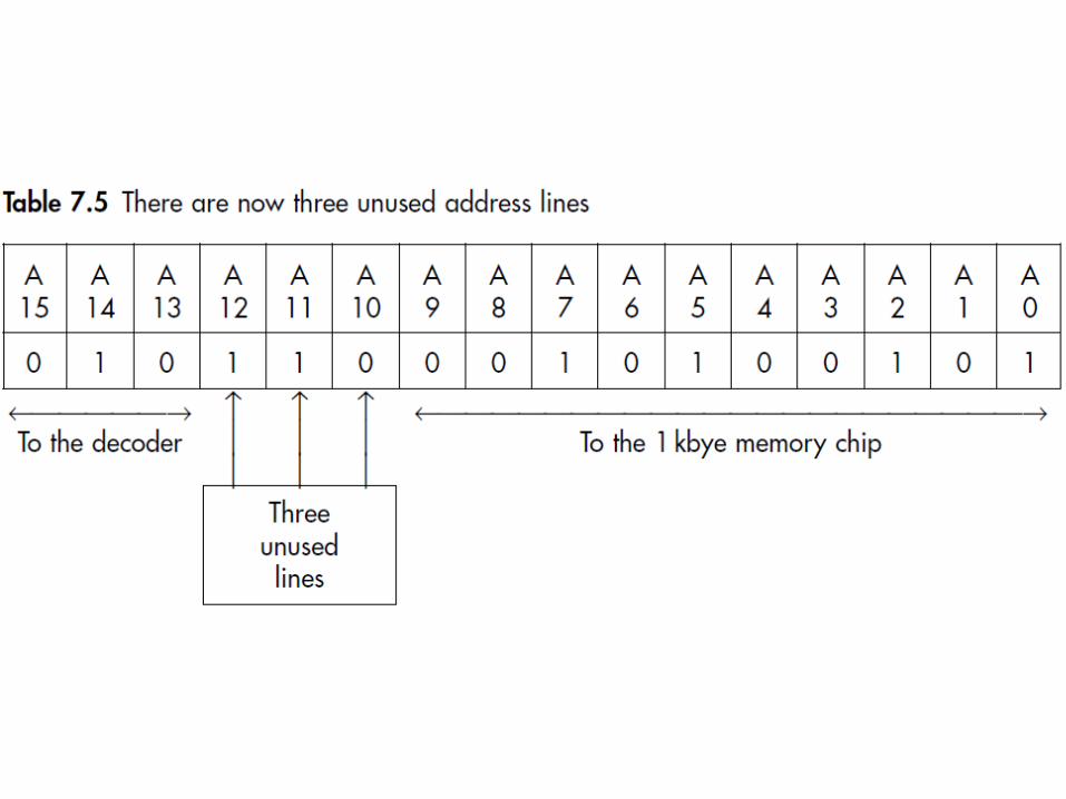
Buses
• A bus is a collection of conductors providing a similar function.– For example, an 8-bit microprocessor normally uses 8 connectors
to carry the data between the microprocessor and the memory.• In a microprocessor-based system we have three main
buses: – the data bus, the address bus and a control bus. – The data bus is a two-way bus carrying data around the system. – The address bus carries addresses and is a one-way bus from the
microprocessor to the memory or other devices. – The control bus is just an association of all the other necessary
connections such as those to the chip select and read/write pins.
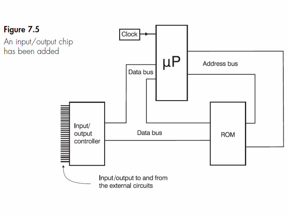
Input/output circuits
• The signal on the data bus has only a very low power level and to be of use it must be amplified.
• If we wanted to send a signal to a printer at 1 ms intervals:– It would be much better to tell the output chip to
do its own timing and thus release the microprocessor for more important jobs.
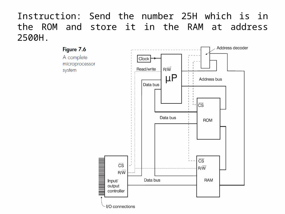
Instruction: Send the number 25H which is in the ROM and store it in the RAM at address 2500H.
• The microprocessor has to collect the instruction from an address in ROM. It does this by putting the address onto the address bus.
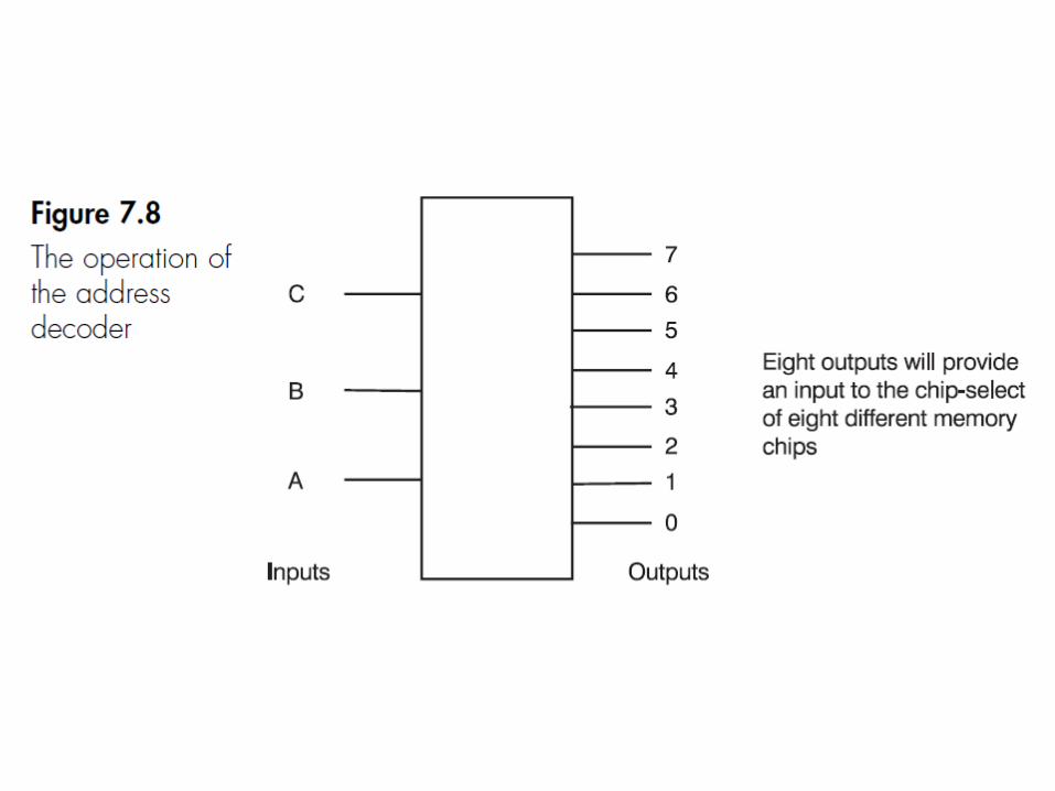
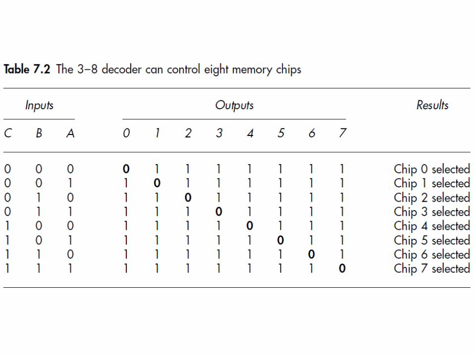
• When the logic gates within the address decoder responds to the input from the address bus the result will be that the ROM is switched on and the other two are kept off.
• Switching on the ROM will mean that it takes in the address from the address bus. As soon as the information is read, the chip select will switch the ROM chip off.
Instruction: Send the number 25H which is in the ROM and store it in the RAM at address 2500H.
• The information which is now on the data bus is read by the microprocessor. It is an instruction which can be interpreted as ‘go to address F600H and read the number that is stored in that address’.
• In response to this instruction, the microprocessor puts the address F600H onto the address bus.
• The address decoder applies this number to its logic gates and this results in the chip select of the ROM chip being switched on again. The ROM chip accepts the address F600H into its row and column decoders and then puts the number 25H onto the data bus.
Instruction: Send the number 25H which is in the ROM and store it in the RAM at address 2500H.
• This number is stored temporarily in the microprocessor.
• The microprocessor then puts the number 2500H onto the address bus and the address decoder puts a signal on the chip select of the RAM chip to switch it on. It then sends a logic 1 on the read/write line. The RAM is switched on and it is told to read the data on the data bus.
Instruction: Send the number 25H which is in the ROM and store it in the RAM at address 2500H.