06 Microprocessor Based Traffic Light Control
37
06 Microprocessor based traffic light control 107 Microprocessor based bank token display 108 Microprocessor based irrigation contro PROJECT REPORT ON “MICROCONTROLLER BASED HOME SECURITY SYSTEM” ABSTRACT Engineering is not only a theoretical study but it is a implementation of all we study for creating something new and making things more easy and useful through practical study. It is an art which can be gained with systematic study, observation and practice. In the college curriculum we usually get the theoretical knowledge of industries, and a little bit of implementation knowledge that how it is works? But how can we prove our practical knowledge to increase the productivity or efficiency of the industry? Don‟t take the chance of becoming victim of burglary, which is often accompanied by violence. Protect our family and valuables with this microcontroller based security system that will let us rest our head knowing that should anyone trying to break into our home, an alarm will go off and the police will be alerted immediately.
Transcript of 06 Microprocessor Based Traffic Light Control

8/2/2019 06 Microprocessor Based Traffic Light Control
http://slidepdf.com/reader/full/06-microprocessor-based-traffic-light-control 1/37
06 Microprocessor based traffic light control107 Microprocessor based bank token display108 Microprocessor based irrigation contro
PROJECT REPORT
ON
“MICROCONTROLLER BASED HOME
SECURITY SYSTEM”
ABSTRACT
Engineering is not only a theoretical study but it is a implementation of all we study for creating
something new and making things more easy and useful through practical study. It is an art
which can be gained with systematic study, observation and practice. In the college curriculum
we usually get the theoretical knowledge of industries, and a little bit of implementation
knowledge that how it is works? But how can we prove our practical knowledge to increase the
productivity or efficiency of the industry?
Don t take the chance of becoming victim of burglary, which is often accompanied by violence.
Protect our family and valuables with this microcontroller based security system that will let us
rest our head knowing that should anyone trying to break into our home, an alarm will go off and
the police will be alerted immediately.

8/2/2019 06 Microprocessor Based Traffic Light Control
http://slidepdf.com/reader/full/06-microprocessor-based-traffic-light-control 2/37
The transmitter section continuously transmits IR rays which are received by the receiver
section. The received signal is further amplified and given to the PLL section, where its
frequency is locked to the transmitted frequency.
When the IR signal is interrupted, the microcontroller starts working as per the program burnt
into the EPROM and control the siren, telephone and cassette player via the respective relays.
CONTENTS:
ChapterChapter: 1. Introduction.Chapter: 2. Circuit description.Chapter: 3. Working of the circuit.Chapter: 4. Used Components.
4.1. Microcontroller (AT89C51)4.2. NE555 IC.4.3. MCT2E Optocouploer.4.4. Regulator (7805, 7809).
Chapter: 5. Other Important Used Components.5.1. BC548 NPN Transistor.5.2. Relay (12V, 200ohm).
Chapter: 6. ApplicationsSummery.Reference.
Chapter: 1
1. Introduction:
Protect our family and valuables with this microcontroller based security system knowing that
should anyone trying to break into our home, an alarm will go ON and the police will be alerted
immediately.
The microcontroller based security system consists of transmitter, receiver, phase locked loopand processing section.

8/2/2019 06 Microprocessor Based Traffic Light Control
http://slidepdf.com/reader/full/06-microprocessor-based-traffic-light-control 3/37
The transmitter section continuously transmits IR rays which are received by the receiver
section. The received signal is further amplified and given to the PLL section, where its
frequency is locked to the transmitted frequency. The transmitter and receiver are arranged such that
the transmitted IR rays fall directly onto the phototransistor LI4GI of the receiver. The signal received by
T2 is amplified by transistor T3 and operational amplifier µA741 (IC2). Series input resistor R8 and
feedback resistor R9 determine the gain of op amplifier IC2. The amplified single so applied to pin 3 of
PLLLM567 (IC3) through capacitor C4.
ICLM567 is highly stable PLL with synchronous AM lock detection and power output circuitry it is
primarily used as frequency decoder which drives a load whenever a sustained frequency falling within itsdetection band is present in its self biased input. The centre frequency of the determined by external
components.
In the absence of any input single, the center frequency of PLL s eternal free running, current control
oscillator is determined by resistor R12 abed capacitor C8.

8/2/2019 06 Microprocessor Based Traffic Light Control
http://slidepdf.com/reader/full/06-microprocessor-based-traffic-light-control 4/37
Preset VR2 is used for tuning IC3 to the desired center frequency in the 6-10 kHz range,
Which should match the modulating frequency of the transmitter? Capacitor C6 and C7 are used as low
pass filter. Ned out filter respectively when the received signal is locked to frequency of transmitter signal
pin 8 of IC3 goes low and LED 1 glows. Since pin 8 is connected to the base of transistor T4 through R13its collector voltage rises. As a result T5 is forward biased to energies the relay RL5 the pole and
normally closed contact of really contact of RL5 are connected to +5v.
When the IR signal is interrupted, the microcontroller starts working as per the program burnt
into the EPROM and control the siren, telephone and cassette player via the respective relays.
Chapter: 2
2. Circuit Description:
8/2/2019 06 Microprocessor Based Traffic Light Control
http://slidepdf.com/reader/full/06-microprocessor-based-traffic-light-control 5/37
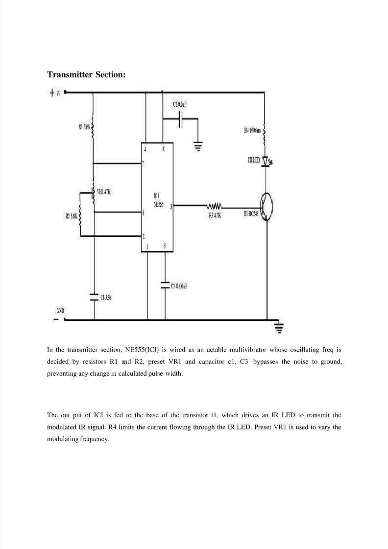
Transmitter Section:
In the transmitter section, NE555(ICI) is wired as an actable multivibrator whose oscillating freq is
decided by resistors R1 and R2, preset VR1 and capacitor c1, C3 bypasses the noise to ground,
preventing any change in calculated pulse-width.
The out put of ICI is fed to the base of the transistor t1, which drives an IR LED to transmit the
modulated IR signal. R4 limits the current flowing through the IR LED. Preset VR1 is used to vary the
modulating frequency.
8/2/2019 06 Microprocessor Based Traffic Light Control
http://slidepdf.com/reader/full/06-microprocessor-based-traffic-light-control 6/37
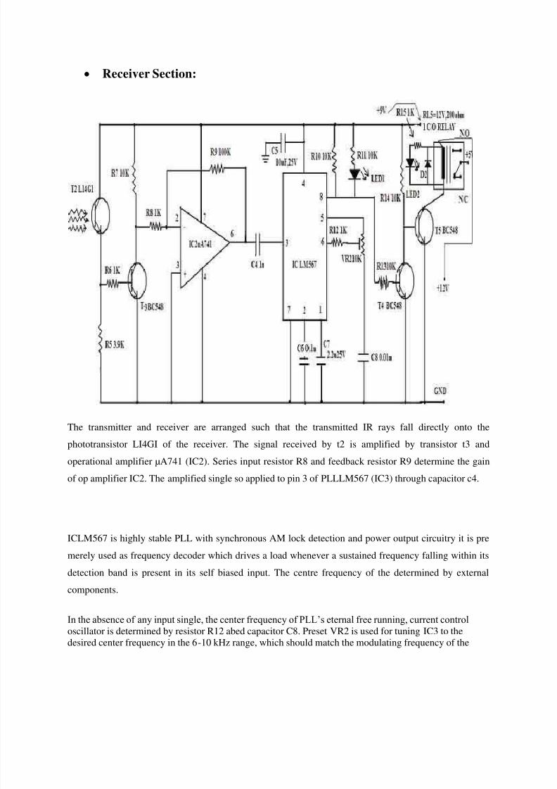
Receiver Section:
The transmitter and receiver are arranged such that the transmitted IR rays fall directly onto the
phototransistor LI4GI of the receiver. The signal received by t2 is amplified by transistor t3 and
operational amplifier µA741 (IC2). Series input resistor R8 and feedback resistor R9 determine the gain
of op amplifier IC2. The amplified single so applied to pin 3 of PLLLM567 (IC3) through capacitor c4.
ICLM567 is highly stable PLL with synchronous AM lock detection and power output circuitry it is pre
merely used as frequency decoder which drives a load whenever a sustained frequency falling within its
detection band is present in its self biased input. The centre frequency of the determined by external
components.
In the absence of any input single, the center frequency of PLL s eternal free running, current controloscillator is determined by resistor R12 abed capacitor C8. Preset VR2 is used for tuning IC3 to thedesired center frequency in the 6-10 kHz range, which should match the modulating frequency of the

8/2/2019 06 Microprocessor Based Traffic Light Control
http://slidepdf.com/reader/full/06-microprocessor-based-traffic-light-control 7/37
transmitter? Capacitor C6 and C7 are used as low pass filter. Ned out filter respectively when the receivedsignal is locked to frequency of transmitter signal pin 8 of IC3 goes low and LED 1 glows. Since pin 8 isconnected to the base of transistor T4 through R13 its collector
voltage rises. As a result T5 is forward biased to energies the relay RL5 the pole and normally closed
contact of really contact of RL5 are connected to +5v.
The low order multiplex address and data lines AD0 though AD7 of IC4 are connected to the EPROM
(IC5) through the latch(IC6), while its high order address line A8 through A10 are directly connected to
the EPROM. Address lines A0 through A7. Are separated from data lines D0 through D7 by latch enable
single.
Address latch – enable pin 30 of the microcontroller is connected to latch enable pin 11 Ic6. When ale
high the latch us transparent. The output changes according the input data when ALE goes low, the low
order address is latched at the input of IC6.
Data lines D0 throughD7 of microcontroller are connected to dated lines of IC5 and IC7 each. Chip sleets
signal for IC5 is generated by RD and IO/M lines with the help of NAND gate. The inverted IO/M signal
provides CS signal through IC7.
IC AT89C51 is general purpose programmable device compatible with most microcontrollers. It has three
programmable ports, any of which can be ports and the remaining eight bits as port c.
The eight bits of ports c can be used as individual bits or grouped in two 4-bits ports namely, c (upper)
and c (lower). Ports A and C are configured as input ports and port B is configured as output port A. is
used for inter detection,portB for activating the siren, cassette player, telephone cradle switch and redial
button and port C for polarity reversal detection.

8/2/2019 06 Microprocessor Based Traffic Light Control
http://slidepdf.com/reader/full/06-microprocessor-based-traffic-light-control 8/37
The circuit for detecting the polarity reversal detection the telephone line is built around optocoupler IC8
and IC9. Normally, TIP is positive with respect to RING lead of telephone line. With the handset in off
position a nominal loop current of 10 mA is assumed to flow through the telephone line. Resistor R23 is
selected as 120 ohms to develop the voltage of
1.2v. when the the dc lines voltage polarity reversal occurs, optocoupler IC8 s internal LED conducts and
LED3 glows to indicate polarity reversal occurs. Simultaneously, optocoupler IC9 s internal LED goes
off and its pin 5 (collector) goes high to provide line – reversal sense signal to AT89C51.
Fig.3 shows the power supply circuit. The AC mains are stepped down by transformer X1 to deliver a
secondary output of 12V AC at 300 ma. The transformer output is rectified by a full-wave bridge rectifier.
Comprising diodes D7 through D10. Capacitor C12 acts as a filter to eliminate ripples. IC10 and IC11
provide regulated 5v and 9V power supplies, respectively. Capacitors C13 and C14 bypass any ripple
present in the regulated out- us. Switch S2 acts as an „on / off switch.
Relay connections:
The cradle switch in the telephone instrument is a double pole, two-way switch. Replace this cradle
switch with the contacts of DPDT relay RL3 as shown in fig.2.Now relay RL3 is
Used to implement the action of lifting the telephone handset.
There are four pads on the PCB of the telephone instrument where cradle switch is connected. The two
pads which are shorted when the telephone handset is placed on the cradle are connected to the normally
closed (N/O) contacts of relay RL3, while the other two pads which are shorted when the handset is off-
hook are connected to to the normally o0pen (N/O) contacts of relay RL3.

8/2/2019 06 Microprocessor Based Traffic Light Control
http://slidepdf.com/reader/full/06-microprocessor-based-traffic-light-control 9/37
Relay RL2 is connected in parallel to the redial button of the telephone instrument. When relay RL3
emerges to emulate lifting of the handset, relay RL2 is energized to switch on the redial button and the
already loaded telephone number of the police station or any other help provider is automatically dialed.
Relay RL4 activates the siren whenever the IR signal being received is interrupted iron soundscontinuously until the user presses the reset button.
Relay RL1 is used to switch on the audio cassette player, in which the user s residential address and alert
message to be conveyed to the police station are prerecorded. The speaker output of the cassette player is
connected to the telephone s microphone to convey the alert message to the police station. The player gets
switched off when the message is over.
Chapter: 3
3. Working of the Circuit:
The transmitting IR LED1 and phototransistor T2 of the receiver are fitted to the gate such the IR rays
emitted by the LED directly fall on the phototransistor.
The IR LED transmits a train of IR pulses. These pulses are received by the receiver and amplified byIC2. Output pin 8 of the PLL (IC3) is low when the PLL network is locked to the transmitter frequency
and relay RL5 energies to make PA line of IC7 low.
When someone walks through the gate to enter your home, the transmitted signal is interrupted. Output
pin 8 of the PLL network goes high and relay RL5 de-energies to make PA0 line of IC7 high. Now the
microprocessor starts working as per the program loaded in the EPROM.
Relay RL4 energies to activate the siren. At the same time, relay RL3 energizes to emulate lifting the
telephone handset off the cradle to provide the dial tone. After a few seconds, relay RL2 energies to short
the redial button contacts. After the loaded number is dialed, it switches off relay RL2. Then relay RL1
turns on the audio player.
Here we have provided the same polarity-reversal detection facility so that the audio player turns on only
when polarity-reversal is detected.

8/2/2019 06 Microprocessor Based Traffic Light Control
http://slidepdf.com/reader/full/06-microprocessor-based-traffic-light-control 10/37
The actual-size, double-size track lay-outs for solder and component sides of the PCB for the 8085
microprocessor-based home security system are shown in figs5 and figs6 , respectively, and their
component layout in fig.7.
Software Program:
Fig. shows the flow-chart of the Assembly language program. The device interface IC (IC7) is initializedwith control word 99H. Ports A and C of IC7 act as input ports, while port B becomes the output port.

8/2/2019 06 Microprocessor Based Traffic Light Control
http://slidepdf.com/reader/full/06-microprocessor-based-traffic-light-control 11/37

8/2/2019 06 Microprocessor Based Traffic Light Control
http://slidepdf.com/reader/full/06-microprocessor-based-traffic-light-control 12/37
After initialization, the AT89C51 microcontroller reads the status of port A. If port A is high, siren is
activated. The telephone goes in off-hook condition and the emergency number is dialed through the
redial button. Redial button gets switched off after the number is dialed. Now the microprocessor reads
the status of port C and checks for the polarity reversal of the telephone line. When polarity reversal is
detected, the audio player turns on to play the message. Otherwise, the process repeats from activation of
the siren followed by emergency number dialing and so on. After delivering the message, the player
automatically gets turned off. The siren sounds until the reset switch is pressed.
Chapter: 4
4. Used Components:
AT89C2051
NE555
uA741 Operational Amplifier
MCT2E Optocoupler
Regulator (7805,7809) BC 548 NPN Transistor
L14G1 Photo Transistor
1N4148 Switching Diode
LED’s ( Red, IR)
Resistor’s
Capacitor’s
Relay’s
Battery’s
These are important components with is use in this projects. Other components like
resistors, capacitors, transistors, inductors used PCB’s etc are not described here.

8/2/2019 06 Microprocessor Based Traffic Light Control
http://slidepdf.com/reader/full/06-microprocessor-based-traffic-light-control 13/37
The details of the important IC’s:
4.1. AT89C51:
Features
• Compatible with MCS- 51™ Products
• 4K Bytes of In-System Reprogrammable Flash Memory – Endurance: 1,000
Write/Erase Cycles
• Fully Static Operation: 0 Hz to 24 MHz
• Three-level Program Memory Lock
• 128 x 8-bit Internal RAM
• 32 Programmable I/O Lines
• Two 16-bit Timer/Counters
• Six Interrupt Sources
• Programmable Serial Channel
• Low-power Idle and Power-down Modes
Description:
The AT89C51 is a low-power, high-performance CMOS 8-bit microcomputer with 4Kbytes of
Flash programmable and erasable read only memory (PEROM). The devices manufactured using
Atmel shigh -density nonvolatile memory technology and incompatible with the industry

8/2/2019 06 Microprocessor Based Traffic Light Control
http://slidepdf.com/reader/full/06-microprocessor-based-traffic-light-control 14/37
standardMCS-51 instruction set and pin out. The on-chip Flash allows the program memory to
be reprogrammed in-system or by a conventional nonvolatile memory programmer. By
combining a versatile 8-bit CPU with Flash on a monolithic chip, the Atmen AT89C51 is a
powerful microcomputer which provides a highly-flexible and cost-effective solution to many
embedded control applications .
Pin Configuration:
Block Diagram:
8/2/2019 06 Microprocessor Based Traffic Light Control
http://slidepdf.com/reader/full/06-microprocessor-based-traffic-light-control 15/37
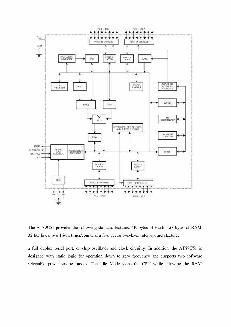
The AT89C51 provides the following standard features: 4K bytes of Flash, 128 bytes of RAM,32 I/O lines, two 16-bit timer/counters, a five vector two-level interrupt architecture,
a full duplex serial port, on-chip oscillator and clock circuitry. In addition, the AT89C51 is
designed with static logic for operation down to zero frequency and supports two software
selectable power saving modes. The Idle Mode stops the CPU while allowing the RAM,

8/2/2019 06 Microprocessor Based Traffic Light Control
http://slidepdf.com/reader/full/06-microprocessor-based-traffic-light-control 16/37
timer/counters, serial port and interrupt system to continue functioning. The Power-down Mode
saves the RAM contents but freezes the oscillator disabling all other chip functions until the next
hardware reset .
Pin Description:
VCC:
Supply voltage.
GND:
Ground.
Port 0
Port 0 is an 8-bit open-drain bi-directional I/O port. As an output port, each pin can sink eight
TTL inputs. When 1s are written to port 0 pins, the pins can be used as high impedance inputs.
Port 0 may also be configured to be the multiplexed low order address/data bus during accessesto external program and data memory. In this mode P0 has internal pull-ups. Port 0 also receives
the code bytes during Flash programming, and outputs the code bytes during program
verification. External pull-ups are required during program verification.
Port 1
Port 1 is an 8-bit bi-directional I/O port with internal pull-ups. The Port 1 output buffers can
sink/source four TTL inputs. When 1s are written to Port 1 pins they are pulled high by the
internal pull-ups and can be used as inputs. As inputs, Port 1 pins that are externally being pulled
low will source current (IIL) because of the internal pull-ups. Port 1 also receives the low-order
address bytes during Flash programming and verification.

8/2/2019 06 Microprocessor Based Traffic Light Control
http://slidepdf.com/reader/full/06-microprocessor-based-traffic-light-control 17/37

8/2/2019 06 Microprocessor Based Traffic Light Control
http://slidepdf.com/reader/full/06-microprocessor-based-traffic-light-control 18/37
RST
Reset input. A high on this pin for two machine cycles while the oscillator is running resets the
device.
ALE/PROG
Address Latch Enable output pulse for latching the low byte of the address during accesses to
external memory. This pin is also the program pulse input (PROG) during Flash
Programming. In normal operation ALE is emitted at a constant rate of 1/6 the oscillator
frequency, and may be used for external timing or clocking purposes. Note, however, that one
ALE pulse is skipped during each access to external Data Memory. If desired, ALE operation
can be disabled by setting bit 0 of SFR location 8EH. With the bit set, ALE is active only during
a MOVX or MOVC instruction. Otherwise, the pin is weakly pulled high. Setting the ALE-
disable bit has no effect if the microcontroller is in external execution mode.
PSEN
Program Store Enable is the read strobe to external program memory. When the AT89C51 is
executing code from external program memory, PSEN is activated twice each machine cycle,
except that two PSEN activations are skipped during each access to external data memory.
EA/VPP
External Access Enable. EA must be strapped to GND in order to enable the device to fetch code
from external program memory locations starting at 0000H up to FFFFH. Note, however, that if
lock bit 1 is programmed, EA will be internally latched on reset. EA should be strapped to
VCC for internal program executions. This pin also receives the 12-volt programming enable
voltage (VPP) during Flash programming, for parts that require 12-volt VPP.
XTAL1

8/2/2019 06 Microprocessor Based Traffic Light Control
http://slidepdf.com/reader/full/06-microprocessor-based-traffic-light-control 19/37
Input to the inverting oscillator amplifier and input to the internal clock operating circuit.
XTAL2
Output from the inverting oscillator amplifier. Unconnected while XTAL1 is driven as shown inFigure 2. There are no requirements on the duty cycle of the external clock signal, since the input
to the internal clocking circuitry is through a divide-by-two flip-flop, but minimum and
maximum voltage high and low time specifications must be observed.
Idle Mode
In idle mode, the CPU puts itself to sleep while all the on chip peripherals remain active. The
mode is invoked by software. The content of the on-chip RAM and all the special functions
registers remain unchanged during this mode. The idle mode can be terminated by any enabled
interrupt or by a hardware reset. It should be noted that when idle is terminated by a hard ware
reset, the device normally resumes program execution, from where it left off, up to two machine
cycles before
The internal reset algorithm takes control. On-chip hardware inhibits access to internal RAM in
this event, but access to the port pins is not inhibited. To eliminate the possibility of an
unexpected write to a port pin when Idle is terminated by reset, the instruction following the one
that invokes Idle should not be one that writes to a port pin or to external memory.
Programming Algorithm:
Before programming the AT89C51, the address, data and control signals should be set up
according to the Flash programming mode table and Figure 3 and Figure 4. To program the
AT89C51, take the
Following steps:
1. Input the desired memory location on the address lines.
2. Input the appropriate data byte on the data lines.

8/2/2019 06 Microprocessor Based Traffic Light Control
http://slidepdf.com/reader/full/06-microprocessor-based-traffic-light-control 20/37
3. Activate the correct combination of control signals.
4. Raise EA/VPP to 12V for the high-voltage programming mode.
5. Pulse ALE/PROG once to program a byte in the Flash array or the lock bits. The byte-writecycle is self-timed and typically takes no more than 1.5 ms. Repeat steps 1 through 5, changing
the address and data for the entire array or until the end of the object file is reached.
Data Polling:
The AT89C51 features Data Polling to indicate the end of a write cycle. During a write cycle, an
attempted read of the last byte written will result in the complement of the written datum on
PO.7. Once the write cycle has been completed, true data are valid on all outputs, and the nextcycle may begin. Data Polling may begin any time after a write cycle has been initiated.
Ready/Busy:
The progress of byte programming can also be monitored by the RDY/BSY output signal. P3.4 is
pulled low after ALE goes high during programming to indicate BUSY. P3.4 is pulled high again
when programming is done to indicate READY.
Program Verify:
If lock bits LB1 and LB2 have not been programmed, the programmed code data can be read
back via the address and data lines for verification. The lock bits cannot be verified directly.
Verification of the lock bits is achieved by observing that their features are enabled.
Chip Erase:
The entire Flash array is erased electrically by using the proper combination of control signals
and by holding ALE/PROG low for 10 ms. The code array is written with al l “1”s. The chip
erase operation must be executed before the code memory can be re-programmed.

8/2/2019 06 Microprocessor Based Traffic Light Control
http://slidepdf.com/reader/full/06-microprocessor-based-traffic-light-control 21/37
Reading the Signature Bytes:
The signature bytes are read by the same procedure as a normal verification of locations 030H,
031H, and 032H, except that P3.6 and P3.7 must be pulled to a logic low. The values returned
are as follows.
(030H) = 1EH indicates manufactured by Atmel
(031H) = 51H indicates 89C51
(032H) = FFH indicates 12V programming
(032H) = 05H indicates 5V programming
Programming Interface
Every code byte in the Flash array can be written and the entire array can be erased by using the
appropriate combination of control signals. The write operation cycle is self timed and once
initiated, will automatically time itself to completion. All major programming vendors offer
worldwide support for the Atmen microcontroller series. Please contact your local programming
vendor for the appropriate software revision.
4.2. NE555 IC:
Features:
• High Current Drive Capability (200mA)

8/2/2019 06 Microprocessor Based Traffic Light Control
http://slidepdf.com/reader/full/06-microprocessor-based-traffic-light-control 22/37
• Adjustable Duty Cycle
• Temperature Stability of 0.005%/°C
• Timing from μ Sec to Hours.
• Turn off Time Less than 2μSec
Applications:
• Precision Timing
• Pulse Generation
• Time Delay Generation
• Sequential Timing
Description:
The LM555/NE555/SA555 is a highly stable controller capable of producing accurate timing
pulses. With monostable operation, the time delay is controlled by one external resistor and onecapacitor. With astable operation, the frequency and duty cycle are accurately controlled with
two external resistors and one capacitor.
Internal Block Diagram:

8/2/2019 06 Microprocessor Based Traffic Light Control
http://slidepdf.com/reader/full/06-microprocessor-based-traffic-light-control 23/37
Monostable Operation:
Monoatable Circuit:

8/2/2019 06 Microprocessor Based Traffic Light Control
http://slidepdf.com/reader/full/06-microprocessor-based-traffic-light-control 24/37
Waveforms of Monostable Operation
Resistance and Capacitance vs.
Time delay (td)
4.3. MCT2E Optocouploer:
8/2/2019 06 Microprocessor Based Traffic Light Control
http://slidepdf.com/reader/full/06-microprocessor-based-traffic-light-control 25/37
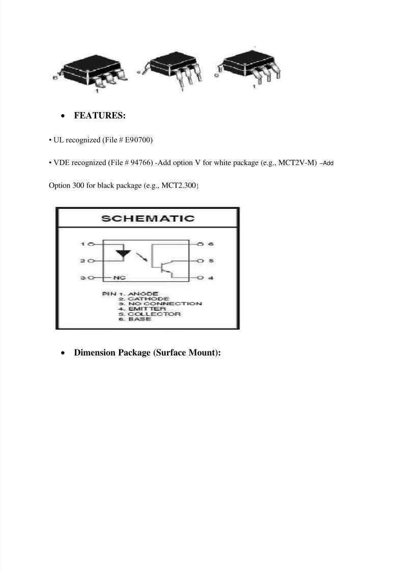
FEATURES:
• UL recognized (File # E90700)
• VDE recognized (File # 94766) -Add option V for white package (e.g., MCT2V-M) –Add
Option 300 for black package (e.g., MCT2.300 )
Dimension Package (Surface Mount):
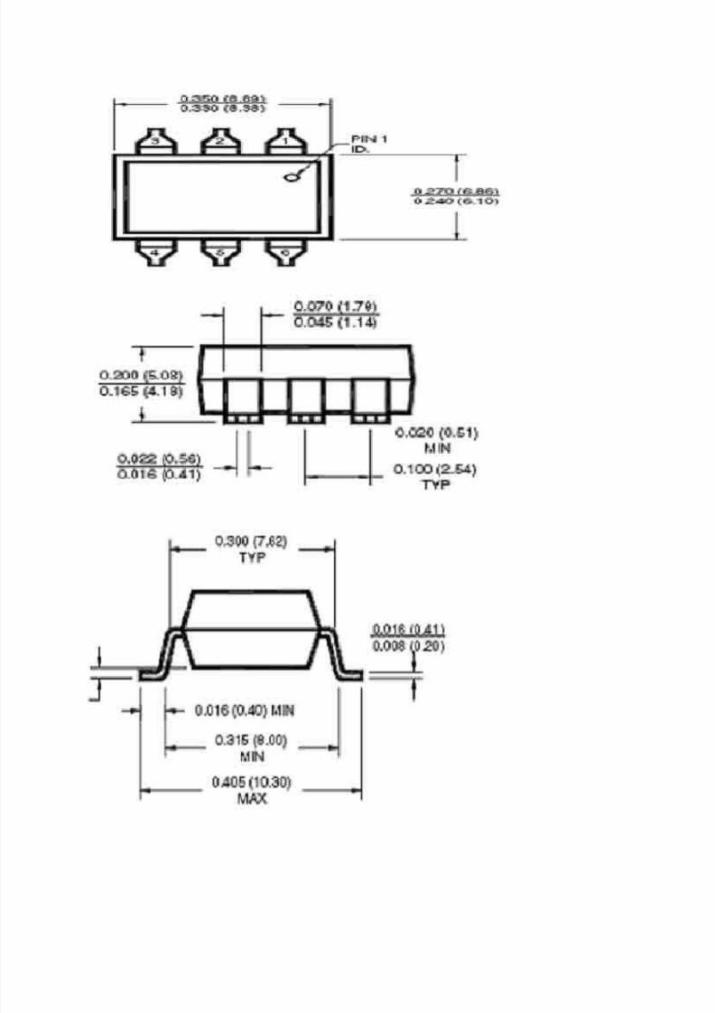
8/2/2019 06 Microprocessor Based Traffic Light Control
http://slidepdf.com/reader/full/06-microprocessor-based-traffic-light-control 26/37

8/2/2019 06 Microprocessor Based Traffic Light Control
http://slidepdf.com/reader/full/06-microprocessor-based-traffic-light-control 27/37
• MCT2 and MCT2E are also available in white package by specifying -M suffix, e.g. MCT2M
APPLICATIONS:
• Power supply regulators
• Digital logic inputs
• Microprocessor inputs
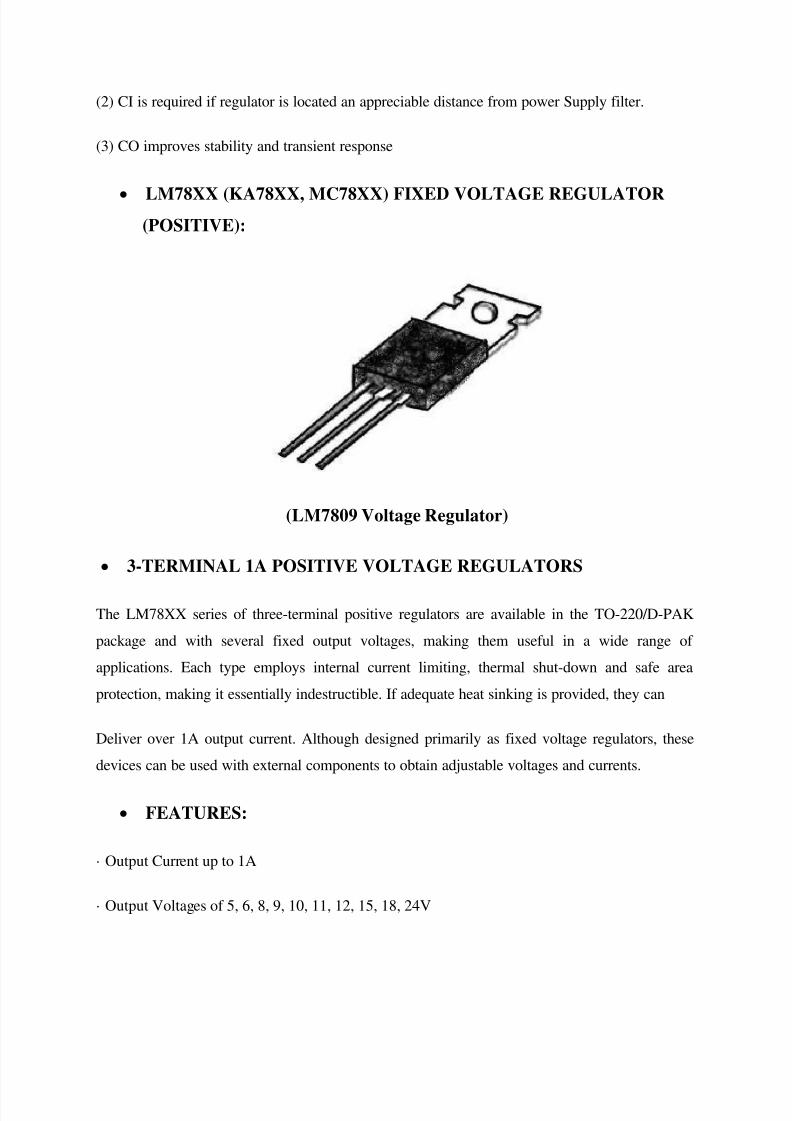
4.4. Voltage Regulator (7805, 7809):
Features:

8/2/2019 06 Microprocessor Based Traffic Light Control
http://slidepdf.com/reader/full/06-microprocessor-based-traffic-light-control 28/37
• Output Current up to 1A
• Output Voltages of 5, 6, 8, 9, 10, 12, 15, 18, 24V
• Thermal Overload Protection
• Short Circuit Protection
• Output Transistor Safe Operating Area Protection
The MC78XX/LM78XX/MC78XXA series of three terminal positive regulators are available in
the TO-220/D-PAK package and with several fixed output voltages, making them useful in a

8/2/2019 06 Microprocessor Based Traffic Light Control
http://slidepdf.com/reader/full/06-microprocessor-based-traffic-light-control 29/37
wide range of applications. Each type employs internal current limiting, thermal shut down and
safe operating area protection, making it essentially indestructible. If adequate heat sinking is
provided, they can deliver over 1A output current. Although designed primarily as fixed voltage
regulators, these devices can be used with external components to obtain adjustable voltages and
currents.
Internal Block Diagram:
Typical Applications:
DC PARAMETERS

8/2/2019 06 Microprocessor Based Traffic Light Control
http://slidepdf.com/reader/full/06-microprocessor-based-traffic-light-control 30/37
LOAD REGULATION
Constant Current Regulator
Notes :
(1) To specify an output voltage. Substitute voltage value for "XX." A common ground isrequired between the input and the
Output voltage. The input voltage must remain typically 2.0V above the output voltage even
during the low point on the input ripple voltage.
8/2/2019 06 Microprocessor Based Traffic Light Control
http://slidepdf.com/reader/full/06-microprocessor-based-traffic-light-control 31/37
(2) CI is required if regulator is located an appreciable distance from power Supply filter.
(3) CO improves stability and transient response
LM78XX (KA78XX, MC78XX) FIXED VOLTAGE REGULATOR(POSITIVE):
(LM7809 Voltage Regulator)
3-TERMINAL 1A POSITIVE VOLTAGE REGULATORS
The LM78XX series of three-terminal positive regulators are available in the TO-220/D-PAK
package and with several fixed output voltages, making them useful in a wide range of
applications. Each type employs internal current limiting, thermal shut-down and safe area
protection, making it essentially indestructible. If adequate heat sinking is provided, they can
Deliver over 1A output current. Although designed primarily as fixed voltage regulators, these
devices can be used with external components to obtain adjustable voltages and currents.
FEATURES:
· Output Current up to 1A
· Output Voltages of 5, 6, 8, 9, 10, 11, 12, 15, 18, 24V

8/2/2019 06 Microprocessor Based Traffic Light Control
http://slidepdf.com/reader/full/06-microprocessor-based-traffic-light-control 32/37
· Thermal Overload Protection
· Short Circuit Protection
· Output Transistor SOA Protection
BLOCK DIAGRAM:
Chapter: 5
5. Other Used Components:
5.1. BC548 NPN Transistor:

8/2/2019 06 Microprocessor Based Traffic Light Control
http://slidepdf.com/reader/full/06-microprocessor-based-traffic-light-control 33/37
This device is designed for use as general purpose amplifiers and switches requiring collector
currents to 300 mA. Sourced from Process 10. See PN100A for characteristics.
NOTES :
1) These ratings are based on a maximum junction temperature of 150 degrees C.
2) These are steady state limits. The factory should be consulted on applications involving pulsed
or low duty cycle operations.
Absolute Maximum Ratings
5.2. Relay (12V, 200 ohm):

8/2/2019 06 Microprocessor Based Traffic Light Control
http://slidepdf.com/reader/full/06-microprocessor-based-traffic-light-control 34/37
A relay is an electrical switch that opens and closes under control of another electrical circuit. In
the original form, the switch is operated by an electromagnet to open or close one or many sets
of contacts. It was invented by Joseph Henry in 1835. Because a relay is able to control an output
circuit of higher power than the input circuit, it can be considered, in a broad sense, to be a form
of electrical amplifier.
Operation:
When a current flows through the coil, the resulting magnetic field attracts an
armature that is mechanically linked to a moving contact. The movement either makes
or breaks a connection with a fixed contact. When the current to the coil is switched
off, the armature is returned by a force that is half as strong as the magnetic force to
its relaxed position. Usually this is a spring, but gravity is also used commonly in
industrial motor starters. Relays are manufactured to operate quickly. In a low voltageapplication, this is to reduce noise. In a high voltage or high current application, this is
to reduce arcing.

8/2/2019 06 Microprocessor Based Traffic Light Control
http://slidepdf.com/reader/full/06-microprocessor-based-traffic-light-control 35/37
If the coil is energized with DC, a diode is frequently installed across the coil, to
dissipate the energy from the collapsing magnetic field at deactivation, which would
otherwise generate a spike of voltage and might cause damage to circuit components.
If the coil is designed to be energized with AC, a small copper ring can be crimped tothe end of the solenoid. This "shading ring" creates a small out-of-phase current,
which increases the minimum pull on the armature during the AC cycle. [1]
The contacts can be either Normally Open (NO) , Normally Closed (NC) , or
change-over contacts.
Normally-open contacts connect the circuit when the relay is activated; the circuit is
disconnected when the relay is inactive. It is also called Form A contact or "make"
contact. Form A contact is ideal for applications that require to switch a high-current
power source from a remote device.
Normally-closed contacts disconnect the circuit when the relay is activated; the circuit is
connected when the relay is inactive. It is also called Form B contact or "break" contact. Form B
contact is ideal for applications that require the circuit to remain closed until the relay is
activated.
Change-over contacts control two circuits: one normally-open contact and one normally-closed
contact with a common terminal. It is also called Form C contact or "transfer" contact.
By analogy with the functions of the original electromagnetic device, a solid-state
relay is made with a thyristor or other solid-state switching device. To achieve
electrical isolation, a light-emitting diode (LED) is used with a photo transistor.
APPLICATION’S:
Basically this project is use as a security purpose. We are using here this
project for providing the security to our home, similarly we can use this
8/2/2019 06 Microprocessor Based Traffic Light Control
http://slidepdf.com/reader/full/06-microprocessor-based-traffic-light-control 36/37
project to protect any restricted area like power plant security, Border
security etc.
Project can be use to operate any device automatically, in this application
the interruption of the infrared waves is use to operate the device. It can use for military purpose.
It can be use as “Power supply regulators”.
Summary:
The microcontroller based security system consists of transmitter, receiver, phase locked loop
and processing section.
The transmitter section continuously transmits IR rays which are received by the receiver
section. The received signal is further amplified and given to t6he PLL section, where its
frequency is locked to the transmitted frequency. The transmitter and receiver are arranged such that
the transmitted IR rays fall directly onto the phototransistor LI4GI of the receiver. The signal received by
t2 is amplified by transistor t3 and operational amplifier µA741 (IC2). Series input resistor R8 and
feedback resistor R9 determine the gain of op amplifier IC2. The amplified single so applied to pin 3 of
PLLLM567 (IC3) through capacitor c4.
ICLM567 is highly stable PLL with synchronous AM lock detection and power output circuitry it is pre
merely used as frequency decoder which drives a load whenever a sustained frequency falling within its
detection band is present in its self biased input. The centre frequency of the determined by external
components.
In the absence of any input single, the center frequency of PLL s eternal free running, current control
oscillator is determined by resistor R12 abed capacitor C8.
Preset VR2 is used for tuning IC3 to the desired center frequency in the 6-10 kHz range,
Which should match the modulating frequency of the transmitter? Capacitor C6 and C7 are used as low
pass filter. Ned out filter respectively when the received signal is locked to frequency of transmitter signal
pin 8 of IC3 goes low and LED 1 glows. Since pin 8 is connected to the base of transistor T4 through R13

8/2/2019 06 Microprocessor Based Traffic Light Control
http://slidepdf.com/reader/full/06-microprocessor-based-traffic-light-control 37/37
its collector voltage rises. As a result T5 is forward biased to energies the relay RL5 the pole and
normally closed contact of really contact of RL5 are connected to +5v.
When the IR signal is interrupted, the microcontroller starts working as per the program burnt
into the EPROM and control the siren, telephone and cassette player via the respective
Reference:
Electronics for you ( Oct. 2004 )
http://www.atmel.com
http:/ /www.electronics4u.com
http:/ /www.ttransenergie.com.au
Microprocessors And Interfacing( Programming & Hardware)-Douglas V.
Hall
Vedam Subrahmanayam- Power Electronics.