Microprocessor Architecture
52
UNIT -1 MICROPROCESSOR ARCHITECTURE
-
Upload
sasidhar-nagisetty -
Category
Documents
-
view
226 -
download
2
description
very usefull
Transcript of Microprocessor Architecture
UNIT -1MICROPROCESSOR ARCHITECTURE
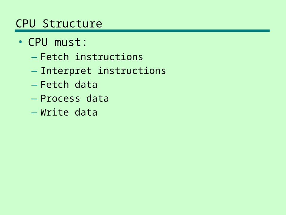
CPU Structure
• CPU must:—Fetch instructions—Interpret instructions—Fetch data—Process data—Write data
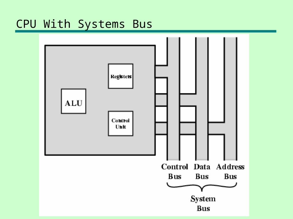
CPU With Systems Bus
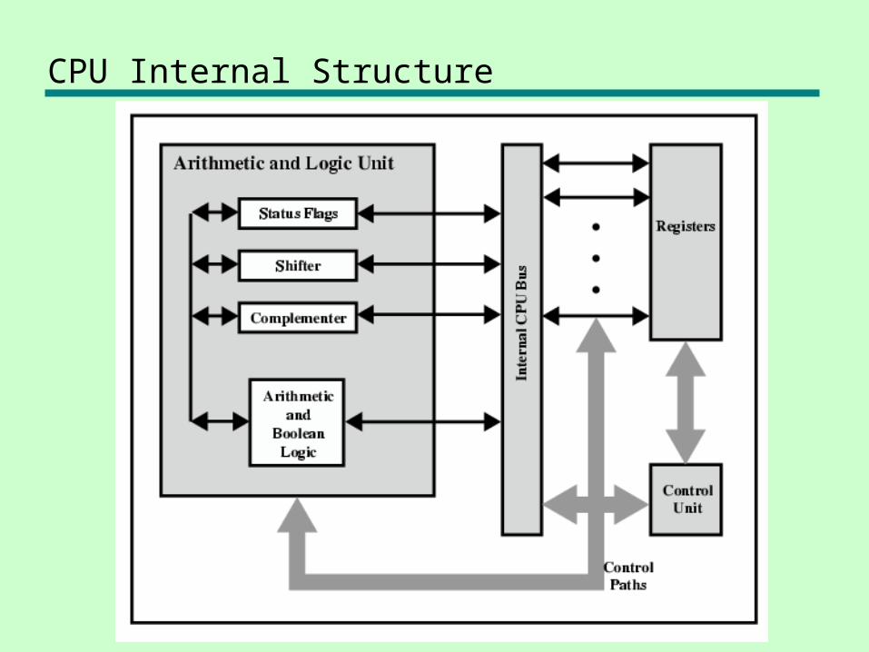
CPU Internal Structure
Registers
• CPU must have some working space (temporary storage) called registers
• Number and function vary between processor designs - One of the major design decisions
• Top level of memory hierarchy
User Visible Registers
• General Purpose• Data• Address• Condition Codes
General Purpose Registers (1)
• May be true general purpose• May be restricted• May be used for data or addressing• Data
—Accumulator
• Addressing—Segment
General Purpose Registers (2)
• Make them general purpose—Increase flexibility and programmer options—Increase instruction size & complexity
• Make them specialized—Smaller (faster) instructions—Less flexibility
How Many GP Registers?
• Between 8 - 32• Fewer = more memory references
How big?
• Large enough to hold full address• Large enough to hold full word• Often possible to combine two data
registers
Condition Code Registers
• Sets of individual bits—e.g. result of last operation was zero
• Can be read (implicitly) by programs—e.g. Jump if zero
• Can not (usually) be set by programs
Control & Status Registers
• Program Counter• Instruction Decoding Register• Memory Address Register• Memory Buffer Register
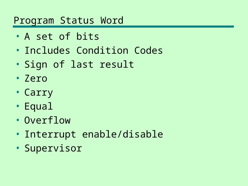
Program Status Word
• A set of bits• Includes Condition Codes• Sign of last result• Zero• Carry• Equal• Overflow• Interrupt enable/disable• Supervisor
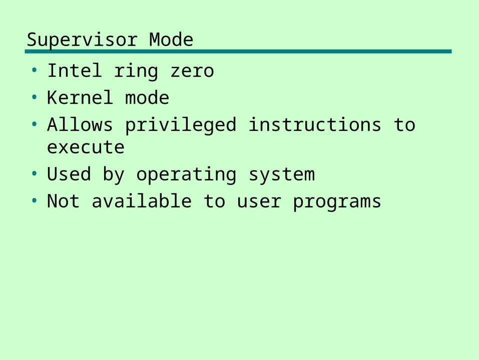
Supervisor Mode
• Intel ring zero• Kernel mode• Allows privileged instructions to execute• Used by operating system• Not available to user programs
Other Registers
• May have registers pointing to:—Process control blocks —Interrupt Vectors
• CPU design and operating system design are closely linked
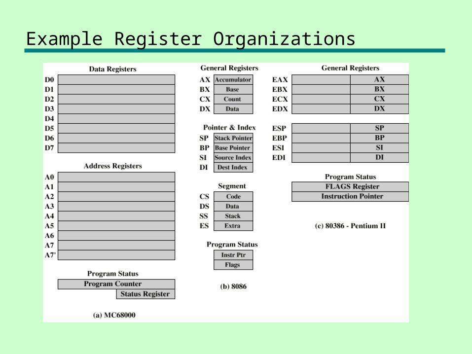
Example Register Organizations
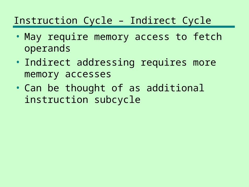
Instruction Cycle – Indirect Cycle
• May require memory access to fetch operands
• Indirect addressing requires more memory accesses
• Can be thought of as additional instruction subcycle

Instruction Cycle with Indirect
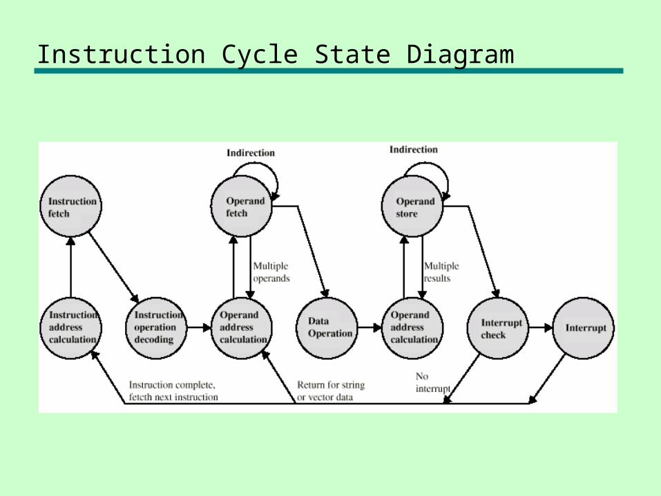
Instruction Cycle State Diagram
Data Flow (Instruction Fetch)
• Depends on CPU design• In general:
• Fetch—PC contains address of next instruction—Address moved to MAR—Address placed on address bus—Control unit requests memory read—Result placed on data bus, copied to MBR,
then to IR—Meanwhile PC incremented by 1
Data Flow (Data Fetch)
• IR is examined• If indirect addressing, indirect cycle is
performed—Right most N bits of MBR transferred to MAR—Control unit requests memory read—Result (address of operand) moved to MBR

Data Flow (Fetch Diagram)
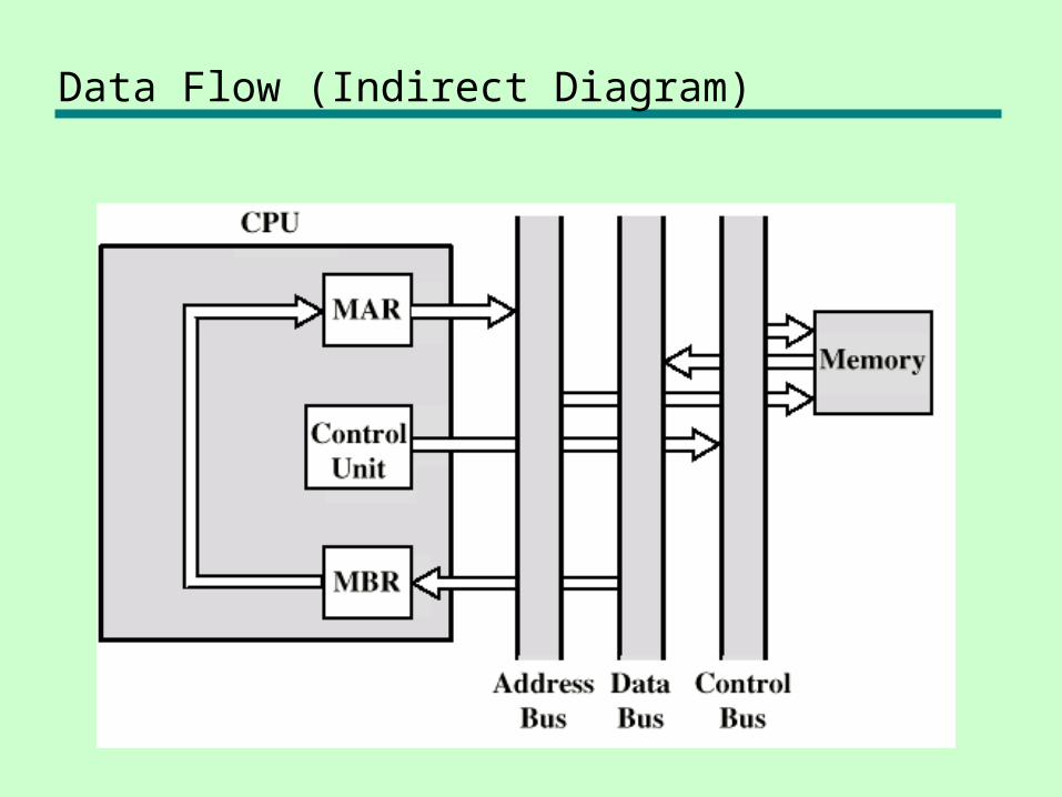
Data Flow (Indirect Diagram)
Data Flow (Execute)
• May take many forms• Depends on instruction being executed• May include
—Memory read/write—Input/Output—Register transfers—ALU operations
Data Flow (Interrupt)
• Simple• Predictable• Current PC saved to allow resumption
after interrupt• Contents of PC copied to MBR• Special memory location (e.g. stack
pointer) loaded to MAR• MBR written to memory• PC loaded with address of interrupt
handling routine• Next instruction (first of interrupt handler)
can be fetched
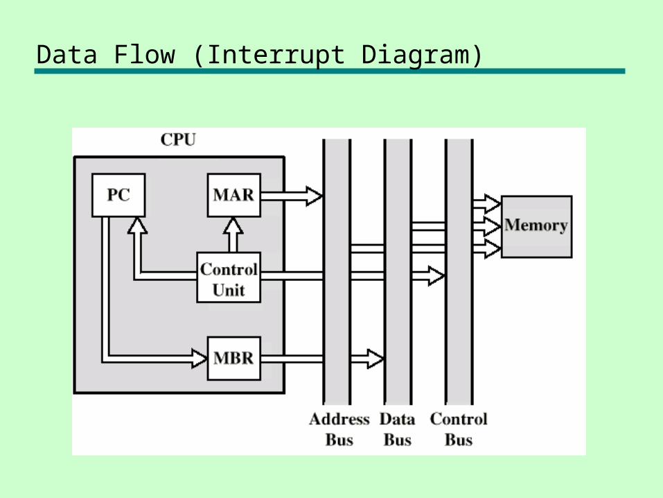
Data Flow (Interrupt Diagram)
Prefetch
• Fetch accessing main memory• Execution usually does not access main
memory• Can fetch next instruction during
execution of current instruction• Called instruction prefetch
Improved Performance
• But not doubled:—Fetch usually shorter than execution—Any jump or branch means that prefetched
instructions are not the required instructions
• Add more stages to improve performance
Pipelining
• Fetch instruction• Decode instruction• Calculate operands (i.e. EAs)• Fetch operands• Execute instructions• Write result
• Overlap these operations
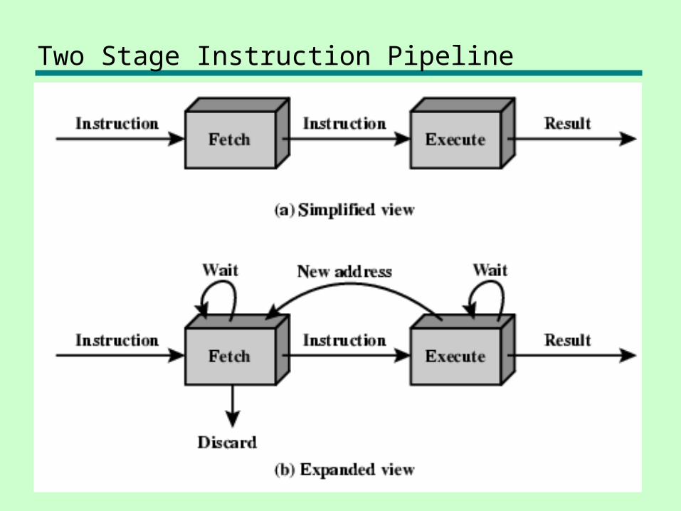
Two Stage Instruction Pipeline
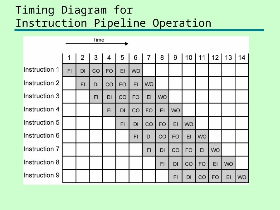
Timing Diagram for Instruction Pipeline Operation
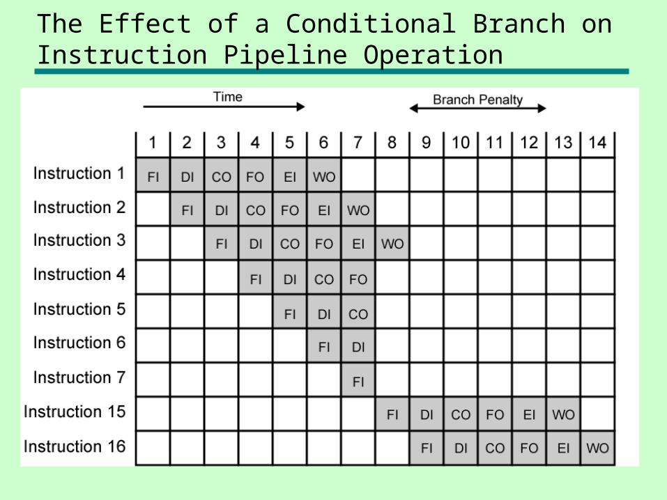
The Effect of a Conditional Branch on Instruction Pipeline Operation
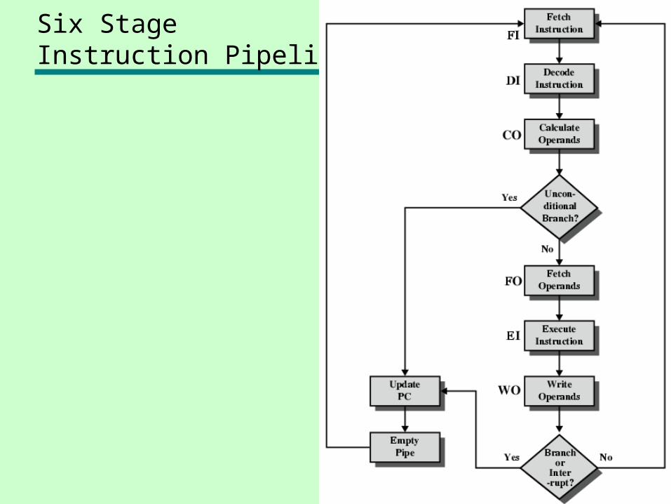
Six Stage Instruction Pipeline
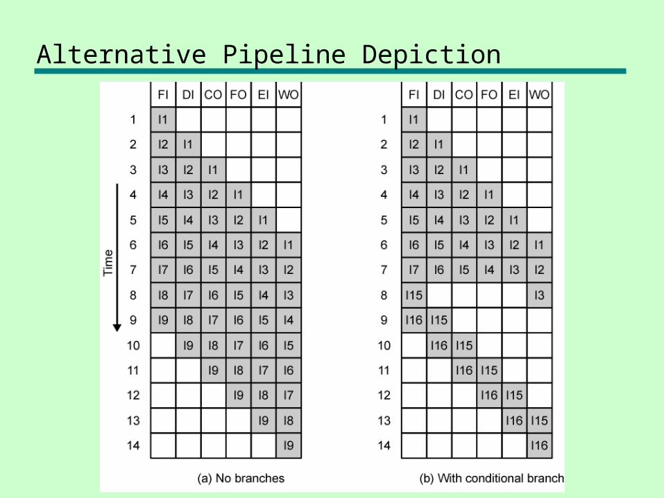
Alternative Pipeline Depiction
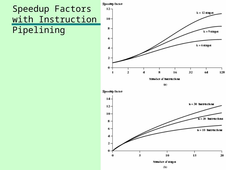
Speedup Factorswith InstructionPipelining
Pipeline Hazards
• Pipeline, or some portion of pipeline, must stall
• Also called pipeline bubble• Types of hazards
—Resource—Data—Control
Resource Hazards• Two (or more) instructions in pipeline need same resource• Executed in serial rather than parallel for part of pipeline• Also called structural hazard• E.g. Assume simplified five-stage pipeline
— Each stage takes one clock cycle• Ideal case is new instruction enters pipeline each clock cycle• Assume main memory has single port• Assume instruction fetches and data reads and writes performed
one at a time• Ignore the cache• Operand read or write cannot be performed in parallel with
instruction fetch• Fetch instruction stage must be idle for one cycle fetching I3
• E.g. multiple instructions ready to enter execute instruction phase• Single ALU
• One solution: increase available resources— Multiple main memory ports— Multiple ALUs
Data Hazards• Conflict in access of an operand location• Two instructions to be executed in sequence• Both access a particular memory or register operand• If in strict sequence, no problem occurs• If in a pipeline, operand value could be updated so as to
produce different result from strict sequential execution• E.g. x86 machine instruction sequence:
• ADD EAX, EBX /* EAX = EAX + EBX• SUB ECX, EAX /* ECX = ECX – EAX
• ADD instruction does not update EAX until end of stage 5, at clock cycle 5
• SUB instruction needs value at beginning of its stage 2, at clock cycle 4
• Pipeline must stall for two clocks cycles• Without special hardware and specific avoidance
algorithms, results in inefficient pipeline usage
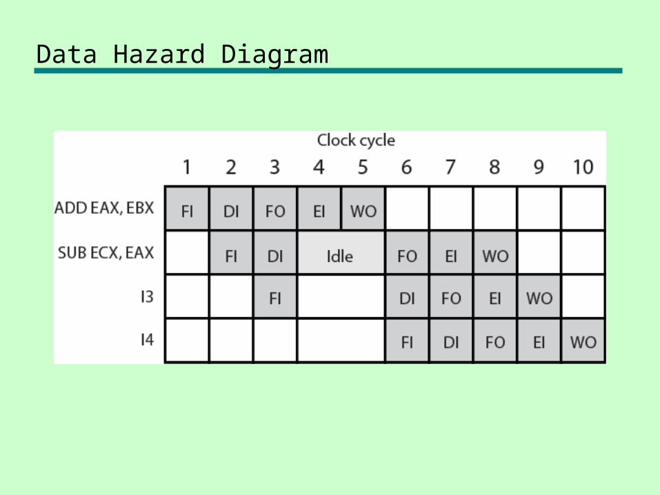
Data Hazard Diagram
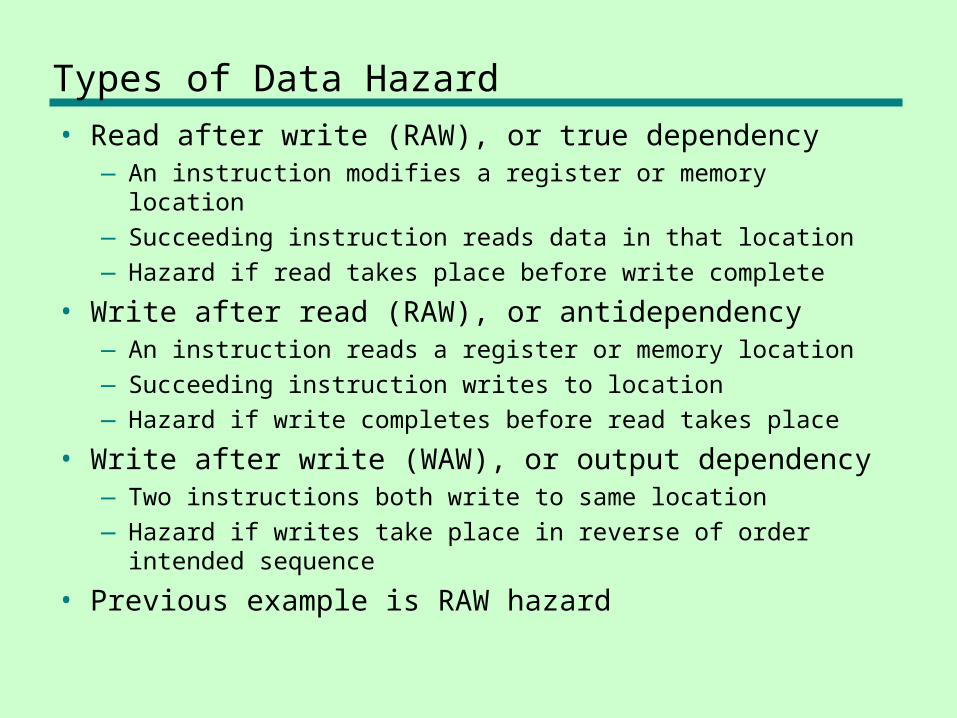
Types of Data Hazard
• Read after write (RAW), or true dependency—An instruction modifies a register or memory location—Succeeding instruction reads data in that location—Hazard if read takes place before write complete
• Write after read (RAW), or antidependency—An instruction reads a register or memory location —Succeeding instruction writes to location—Hazard if write completes before read takes place
• Write after write (WAW), or output dependency—Two instructions both write to same location—Hazard if writes take place in reverse of order intended
sequence
• Previous example is RAW hazard
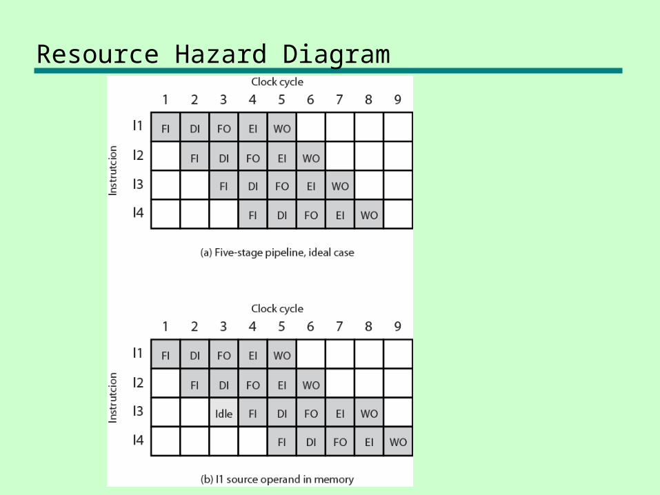
Resource Hazard Diagram
Control Hazard
• Also known as branch hazard• Pipeline makes wrong decision on branch
prediction• Brings instructions into pipeline that must
subsequently be discarded• Dealing with Branches
—Multiple Streams—Prefetch Branch Target—Loop buffer—Branch prediction—Delayed branching
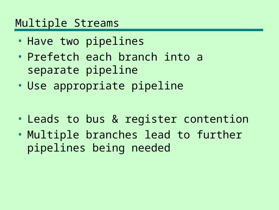
Multiple Streams
• Have two pipelines• Prefetch each branch into a separate
pipeline• Use appropriate pipeline
• Leads to bus & register contention• Multiple branches lead to further pipelines
being needed
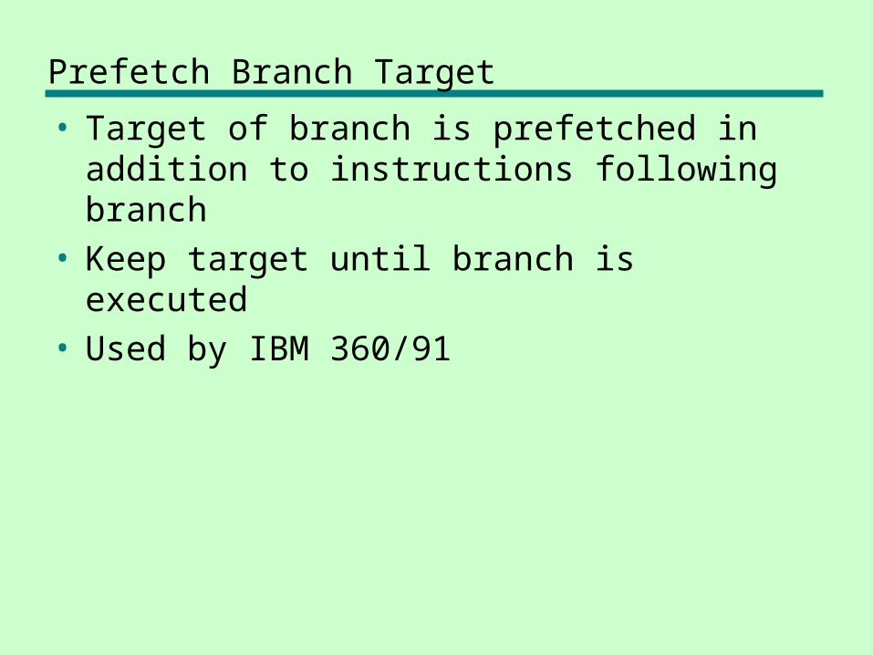
Prefetch Branch Target
• Target of branch is prefetched in addition to instructions following branch
• Keep target until branch is executed• Used by IBM 360/91
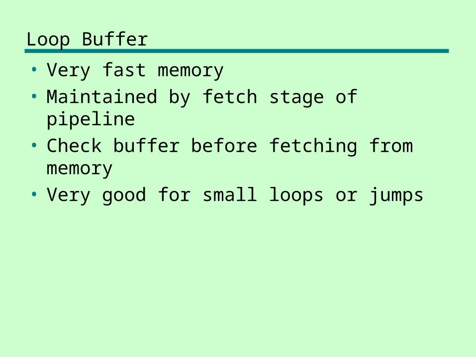
Loop Buffer
• Very fast memory• Maintained by fetch stage of pipeline• Check buffer before fetching from memory• Very good for small loops or jumps
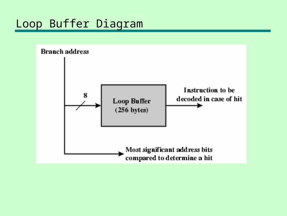
Loop Buffer Diagram
Branch Prediction (1)
• Predict never taken—Assume that jump will not happen—Always fetch next instruction
• Predict always taken—Assume that jump will happen—Always fetch target instruction
Branch Prediction (2)
• Predict by Opcode—Some instructions are more likely to result in a
jump than others—Can get up to 75% success
• Taken/Not taken switch—Based on previous history—Good for loops—Refined by two-level or correlation-based
branch history
• Correlation-based—In loop-closing branches, history is good
predictor—In more complex structures, branch direction
correlates with that of related branches– Use recent branch history as well
Branch Prediction (3)
• Delayed Branch—Do not take jump until you have to rearrange
instructions
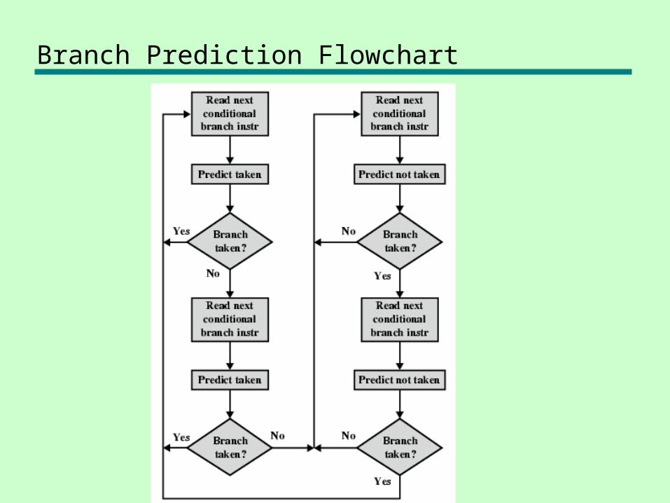
Branch Prediction Flowchart
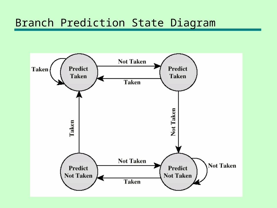
Branch Prediction State Diagram
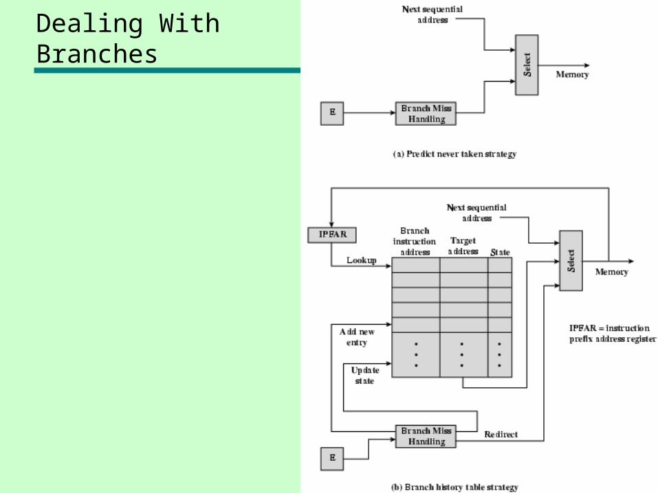
Dealing With Branches