Microneedle Based ECG – Glucose Painless MEMS Sensor with ...
17
HAL Id: hal-01629596 https://hal.inria.fr/hal-01629596 Submitted on 6 Nov 2017 HAL is a multi-disciplinary open access archive for the deposit and dissemination of sci- entific research documents, whether they are pub- lished or not. The documents may come from teaching and research institutions in France or abroad, or from public or private research centers. L’archive ouverte pluridisciplinaire HAL, est destinée au dépôt et à la diffusion de documents scientifiques de niveau recherche, publiés ou non, émanant des établissements d’enseignement et de recherche français ou étrangers, des laboratoires publics ou privés. Distributed under a Creative Commons Attribution| 4.0 International License Microneedle Based ECG – Glucose Painless MEMS Sensor with Analog Front End for Portable Devices Miguel Teixeira, Camilo Velez, Dian Li, João Goes To cite this version: Miguel Teixeira, Camilo Velez, Dian Li, João Goes. Microneedle Based ECG – Glucose Painless MEMS Sensor with Analog Front End for Portable Devices. 8th Doctoral Conference on Computing, Electrical and Industrial Systems (DoCEIS), May 2017, Costa de Caparica, Portugal. pp.463-478, 10.1007/978-3-319-56077-9_45. hal-01629596
Transcript of Microneedle Based ECG – Glucose Painless MEMS Sensor with ...
HAL Id: hal-01629596https://hal.inria.fr/hal-01629596
Submitted on 6 Nov 2017
HAL is a multi-disciplinary open accessarchive for the deposit and dissemination of sci-entific research documents, whether they are pub-lished or not. The documents may come fromteaching and research institutions in France orabroad, or from public or private research centers.
L’archive ouverte pluridisciplinaire HAL, estdestinée au dépôt et à la diffusion de documentsscientifiques de niveau recherche, publiés ou non,émanant des établissements d’enseignement et derecherche français ou étrangers, des laboratoirespublics ou privés.
Distributed under a Creative Commons Attribution| 4.0 International License
Microneedle Based ECG – Glucose Painless MEMSSensor with Analog Front End for Portable Devices
Miguel Teixeira, Camilo Velez, Dian Li, João Goes
To cite this version:Miguel Teixeira, Camilo Velez, Dian Li, João Goes. Microneedle Based ECG – Glucose PainlessMEMS Sensor with Analog Front End for Portable Devices. 8th Doctoral Conference on Computing,Electrical and Industrial Systems (DoCEIS), May 2017, Costa de Caparica, Portugal. pp.463-478,�10.1007/978-3-319-56077-9_45�. �hal-01629596�
Microneedle Based ECG – Glucose Painless
MEMS Sensor with Analog Front End for
Portable Devices
Miguel Lima Teixeira1,2, Camilo Velez2, Dian Li3 and João Goes1,
1 Centre for Technologies and Systems (CTS) – UNINOVA, Dept. of Electrical Engineering
(DEE), Faculty of Sciences and Technology (FCT NOVA), NOVA University of Lisbon,2829-
516, Monte da Caparica, Portugal
[email protected] 2 Electrical and Computer Engineering Dept. (ECE), University of Florida,
32611, Gainesville, Florida, USA 3 Schepens Eye Research Institute, Massachusetts Eye and Ear,
02114, Boston, Massachusetts, USA
Abstract. A portable microelectromechanical system (MEMS) for mobile
phones, or other portable devices, that measures body electrical signals, as well
as, extracts transdermal biological fluid for invivo analysis is proposed. This
system integrates two sensing methods: three points finger electrocardiography
(ECG) and glucose monitoring, through one electrode with a microneedle-
array. This work presents the: (1) device modeling and microneedle-array’
fabrication method, (2) signal processing and biasing circuitry’ design and
simulation, (3) Analog Front End (AFE) for measured signals, and (4) Glucose
sensor characterization. Design parameters and geometries are obtained by
solving the capillarity model inside the microneedles and running optimization
numeric methods. The AFE consists in a differential band pass filter that
provides amplification, filtering, and noise rejection. This work presents clear
technological innovation, for its miniaturization and integration of known
biological signals’ measurement methods in a portable Smart System, which
points in the direction of Internet of Things’ goals.
Keywords: Electrocardiogram, ECG, Glucose, Sensor, Microneedles, MEMS,
Electrodes, Mobile Phones, Cellphones, Electronics, Biological Signals,
Healthcare, Portable
1 Introduction
Many organs in human body, such as heart, brain, and muscles, produce measurable
electrical signals [1] and their detection is necessary to collect clinical information
that permits health diagnosis that many times prevent body failures. In order to
monitor health conditions such as Diabetes, it is also necessary to evaluate enzyme’s
concentration in body fluid [2].
458 M. L. Teixeira et al.
According to the World Health Organization, cardiovascular diseases are the main
cause of death in the world and 422million people worldwide had diabetes in 2015,
causing an average of 1.5milion deaths per year, as in 2012
(http://www.who.int/diabetes/en/). Portable sensors that can measure biological
signals related with those illnesses and prevent body failure, are desired to be
integrated in our normal life. Further more, the healthcare’ current and future trend is
to give patients the ability to monitor their biological signals, making health diagnosis
and at certain times preventing serious health conditions, during their normal day life,
reducing significantly the hospital costs. Mobile phones are excellent candidates to be
carriers of such portable sensors, due to their omnipresence in our daily lives and
because general population keeps them near themselves, as much as possible, for
communication purposes. This work intends to combine those facts proposing a
MEMS system that integrates both sensing methods (ECG - Glucose) in one
electrode, using microneedles.
One of the most important techniques to measure electrical signals in clinic and
biomedical application is the ECG (electrocardiogram), which records the electrical
activities of the heart over time [1][3][4][5][6][7]. The standard commercial ECG
electrodes utilize an electrolytic gel to form conductive interface between skin and
electrode. Using modern microsystem design techniques, it is possible to eliminate the
use of gel by creating and using microneedles as electrodes [1][4][8]. At the same
time, those microneedles can be used to extract interstitial fluid (ISF) to perform
enzyme based diagnostic test, as shown in [9][10][11][12]. Due to careful
microneedle array design the sensor is painless, because the length of microneedles is
less than 500µm and so they don’t reach the pain sensitive dermis’ area, which will be
explained in section 3.2.1. These concepts were applied in this device.
This work is divided in three main areas: microneedle fabrication, microfluidics for
glucose sensor, and sensors’ and AFE’ electrical characterization. The microneedles
for ECG electrodes and glucose electrodes share the same fabrication process. In this
approach the microfluidic and electric models can be separated, because the ISF is
static inside the channel during the glucose measurement. The link between both
electrical sensors is the reference signal. A circuit for amplifying, eliminating noise
and filtering is proposed for both systems, to connect them with a microcontroller.
The PhD study in which this work is being developed has the following research
question and hypothesis: Research question: What would be a suitable way to do a
low power system on chip (100s of µW) that performs advanced computations for
low frequency signals (below 10kHz) as the brain does, as for example pattern
recognition - namely Electrocardiogram (ECG) complete Arrhythmia detection, or
fully implanted closed loop Brain Machine Interface (BMI) with brain signals’
complex interpretation; without the use of a general purpose CPU? Hypothesis: One
possible way is to develop a system on chip inspired in the brain that uses
neurotechnology and neuromorphic circuits, creating an amplitude to time conversion
with an Integrate and Fire circuit, which gives a stream of pulses. That system can
then use pulse processing to do computations with the output pulses, for example with
an automaton - without using conventional digital signal processing (DSP). If such
kind of system is designed and prototyped then it may do these advanced
computations with power consumption below 100µW. Because its pulse timing

Microneedle Based ECG 459
structure only has information for relevant input amplitudes defined by the user,
reducing the redundancy and lowering the hardware specifications.
The motivation of this work is presented next: With this power consumption, the
system could be implanted in the Brain as a battery less standalone device to
compensate for loss brain function, or could be used as a small ECG recording and
arrhythmia detection device that is in contact with the patient chest. Currently these
kinds of devices don’t exist for ECG, or have very simple functions in the case of
BMI, due to the limitation in computation power of such systems on chip.
2 Contribution to Smart Systems
This work presents clear technological innovation in a portable cellphone with smart
sensors that measure body signals of the upmost importance, as for its miniaturization
and integration of known biological signals’ measurement methods in a portable
Smart System, which points in the direction of Internet of Things’ goals.
Moreover, the present work shows a clear contribution to Smart Systems as it
paves the path of integrating healthcare and fitness solutions directly in mobile
devices, that are one of the most used nodes to access Internet of things (IoT). In an
IoT era, these are important developments to improve humans’ daily life.
3 Device Design
The system was divided in four major modules to facilitate the design process: the
microfluidic model that governs the microneedle fabrication, the glucose sensor, the
ECG electrode, and the AFE for both physical measurements. Every module is
independent from the others in terms of modeling, simulations and development
predictions. The microfluidic model and the glucose sensor can be independent,
because the method described in this document to monitor the glucose is for zero flow
measurements. In the other hand, the ECG and the glucose sensor can be independent,
because they will only share the reference electrode and the voltage in this electrode
can be set as a design parameter for both modules.
3.1 Capillarity Modeling
Every microneedle that will be inserted inside the dermis of the human skin will
experiment a capillarity drawn action. As explained in [9], [13], and [14], the ISF
inside the dermis area of the skin will have a different pressure as compared with the
atmosphere. Difference in pressures and the interactions of the fluid with the needle
walls will create forces (van der Waals, dipole-dipole interaction, London dispersion–
fluctuating induced pole, and hydrogen bonds) that will contribute to changes on the
surface tension of the fluid at the interface. Changes on the surface tension will
generate the so-called capillarity drawn. Equation (1) shows the pressure difference in

460 M. L. Teixeira et al.
terms of liquid-gas surface tension (γlg) the contact angle between the liquid (θ), the
volume and the solid (Asl) and liquid area (Alg).
.
(1)
Figure 5.4, page 96, of reference [14] presents the capillary rise in a vertically
standing cylindrical microchannel. As shown in that figure, the liquid will flow inside
the needle until it reaches the distance h. A simplified model for h was demonstrated
in [13] and can be expressed as:
h = (2∙γlg∙cos(θ))/(ρ∙g∙a) . (2)
Where ρ is the fluid density, g the gravity constant, and a the needle’ radius.
This maximum drawn distance h will be used later in this paper to optimize the
design geometry.
3.2 Glucose Sensor
3.2.1 Operating Principles
The relationship between glucose concentrations in ISF and blood was studied in the
past. In reference [15] the author compared the venous, capillary blood glucose and
ISF glucose concentration in one subject during 3 days. A strong correlation was
found which could lead to the useful method of measuring the glucose concentration
from ISF instead of directly from blood. As the ISF can be extracted from the first
layers of the skin, the measurement of glucose concentration from ISF can be
painless. This is accomplished by making the microneedles for extraction of ISF
smaller than 500µm long so they don’t touch nerve cells when inserted in the skin.
This is not possible in the extraction of blood that is always a process with some
degree of pain. Thus, a small microneedle based glucose sensor can be designed. This
is a major advantage of ISF glucose sensors as they can be painless, if designed
properly. Comparing to usual commercially available blood glucose meters, for which
the sample extraction is painful and can cause sensibility and irritation in the area of
skin where the sample was taken, possibly making the user to have to switch the
measurement location, between measurements.
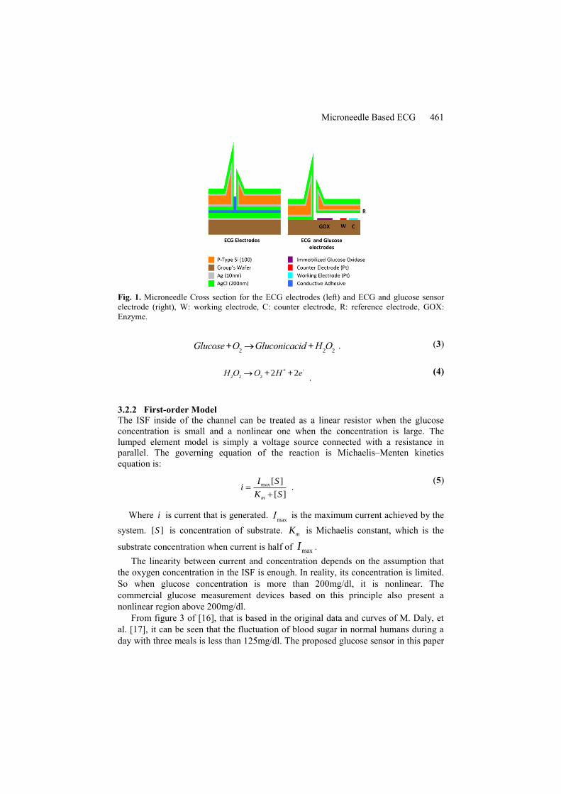
Fig. 1 presents the glucose sensor’ cross section view. The interstitial fluid (ISF)
collected by the microneedle first flows over glucose oxidase (GOX), which is
immobilized in the channel, Fig. 1. GOX will catalyze the glucose oxidation process
to generate gluconic acid and hydrogen peroxide, equation (3). Then hydrogen
peroxide when in contact with the working electrode will be decomposed into water
and electrons, equation (4). Such electrons increase the ISF’s electrical conductivity.
A 0.7V potential difference is added between the working electrode and the reference
electrode that will induce a current. According to the whole reaction’s equation the
concentration of glucose in ISF is proportional to this current amplitude [10].
Microneedle Based ECG 461
Fig. 1. Microneedle Cross section for the ECG electrodes (left) and ECG and glucose sensor
electrode (right), W: working electrode, C: counter electrode, R: reference electrode, GOX:
Enzyme.
Glucose+O2®Gluconicacid +H
2O
2 . (3)
H2O
2®O
2+ 2H
++ 2e
-
. (4)
3.2.2 First-order Model
The ISF inside of the channel can be treated as a linear resistor when the glucose
concentration is small and a nonlinear one when the concentration is large. The
lumped element model is simply a voltage source connected with a resistance in
parallel. The governing equation of the reaction is Michaelis–Menten kinetics
equation is:
max [ ]
[ ]m
I Si
K S
. (5)
Where i is current that is generated. Imax
is the maximum current achieved by the
system. [ ]S is concentration of substrate.
mK is Michaelis constant, which is the
substrate concentration when current is half of maxI .
The linearity between current and concentration depends on the assumption that
the oxygen concentration in the ISF is enough. In reality, its concentration is limited.
So when glucose concentration is more than 200mg/dl, it is nonlinear. The
commercial glucose measurement devices based on this principle also present a
nonlinear region above 200mg/dl.
From figure 3 of [16], that is based in the original data and curves of M. Daly, et
al. [17], it can be seen that the fluctuation of blood sugar in normal humans during a
day with three meals is less than 125mg/dl. The proposed glucose sensor in this paper
462 M. L. Teixeira et al.
will work properly, because the linear region of the sensor is larger than the ordinary
human glucose concentration region: 3mg/dl to 125mg/dl [16], [17]. Moreover, when
the blood sugar is at higher values, it is still possible to make a measurement by using
a table stored in the micro controller memory.
3.2.3 Glucose Sensor Device Performance
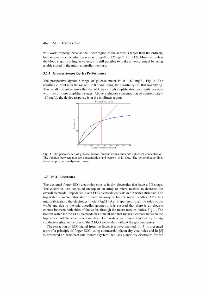
The prospective dynamic range of glucose meter is: 0—180 mg/dl, Fig. 2. The
resulting current is in the range 0 to 0.86nA. Thus, the sensitivity is 0.0048nA*dl/mg.
This small current requires that the AFE has a high amplification gain, only possible
with two or more amplifiers stages. Above a glucose concentration of approximately
180 mg/dl, the device response is in the nonlinear region.
0 50 100 150 200 250 300 350 4000
0.5
1
1.5Michaelis Menten kinetics
Substrate concentration Unit: mg/dL
Curr
ent
unit:n
A
Fig. 2. The performance of glucose sensor, current versus substrate (glucose) concentration.
The relation between glucose concentration and current is in blue. The perpendicular lines
show the prospective dynamic range
3.3 ECG Electrodes
The designed finger ECG electrodes consist in dry electrodes that have a 3D shape.
The electrodes are deposited on top of an array of micro needles to decrease the
overall electrode’ impedance. Each ECG electrode consists in a 2-wafer structure. The
top wafer is micro fabricated to have an array of hollow micro needles. After this
microfabrication, the electrodes’ metal (AgCl +Ag) is sputtered in all the sides of the
wafer and due to the microneedles geometry it is ensured that there is an electric
contact between both sides of the wafer, through the micro needles’ holes, Fig. 1. The
bottom wafer for the ECG electrode has a metal line that makes a contact between the
top wafer and the electronic circuitry. Both wafers are joined together by an Ag
conductive glue, in the case of the 2 ECG electrodes, without the glucose sensor.
The extraction of ECG signal from the finger is a novel method. In [3] is presented
a proof a principle of finger ECG, using commercial planar dry electrodes and in [5]
is presented an heart beat rate monitor system that uses planar dry electrodes for the
Microneedle Based ECG 463
fingers. The micro needle based electrode for ECG is also a novel approach.
Reference [8] shows the microneedle device with a chamber, in the back of the
microneedle structure, containing a conductive gel, to improve the conductance of
these type of electrodes. It has been shown that dry microneedle electrodes are
capable of acquiring signals from ECG, electromyography (EMG) and even electro
encephalography (EEG), signals that are lower voltage signals, than ECG and EMG,
and so require a very low impedance electrode, [1] and [4]. These microneedles’s
electrodes were designed to record ECG in the human chest. As an ECG measurement
device has never been integrated directly in a cell phone.
The first order model for the ECG measurement and the lumped element model for
the skin and electrode is presented in [1] and [18]. To do an ECG measurement it is
required to use two active electrodes, in two fingers, or one finger and hand, and a
third reference electrode in the other hand, or in another finger, or in a different zone.
3.3.1 ECG Device Performance
An estimate of the ECG electrodes’ device performance was made. The electrode area
is the area of the whole device, without electronic circuitry, as the electrode metal
layer is deposited over all the microneedles in the array: electrode
area=3.8mm*2.5mm with a AgCL layer, 25nm thick.
The maximum input signal range is -1mV to 1mV. The ECG electronic circuitry
performs an amplification of 500 times, it has to have a linear response from 0.05Hz
until 500Hz, that is half of the sampling frequency so it can measure accurately each
one of the peaks that make the ECG QRSPT complex, and measure a minimum
detectable signal of 5µV. These and other specifications are presented in the next
tables:
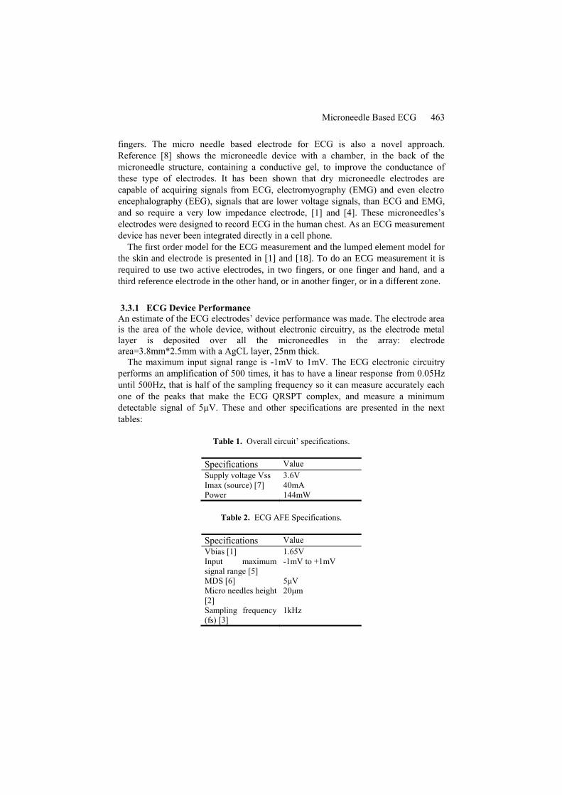
Table 1. Overall circuit’ specifications.
Specifications Value
Supply voltage Vss 3.6V
Imax (source) [7] 40mA
Power 144mW
Table 2. ECG AFE Specifications.
Specifications Value
Vbias [1] 1.65V
Input maximum
signal range [5]
-1mV to +1mV
MDS [6] 5μV
Micro needles height
[2]
20μm
Sampling frequency
(fs) [3]
1kHz

464 M. L. Teixeira et al.
To accomplish these circuit requirements it is important that the circuit has low
noise. More details about the electronic circuits are given in section 5.
3.4 Design Optimization
In order to obtain the geometry values to generate the proper mask for the fabrication
process it is necessary to analyze the behavior of the microfluidic module and its
interaction with the human skin. Every microneedle will experiment the capillarity
drawn for the ISF. It is necessary to design the system with the proper length so the
ISF can fill the needle and the micro channel covering the electrodes. This will be the
most important parameter to be considering for the mask design. Considering this
parameter an optimization problem can be written in order to maximize the fluid
volume inside the needle (cylinder volume) and the channel (rectangular channel).
Fig. 3 shows the distances for the fluidic module.
Fig. 3. Left: . Standard format for the optimization problem. Objective Function, constraints
(from 1 to 3) and boundaries (4 to 6). Right: Microneedle inserted in human skin. Geometry
variables used in the optimization process. Main dimension constrains related with skin
interaction are shown.
The optimization problem can be written in the standard format as in Fig.3.
Constrains for this problem include: 1) the capillarity equation shown in (2) with the
ISF ρ=1060 kg/m3 [18], the ISF surface tension Γ=60mJ/m2 [19], and the contact
angle θ=110° [20] between ISF and needle walls. 2) Represent the wafer thickness. 3)
Is the maximum needle’ dimension in order to avoid reaching dermis’ pain sensitive
area according to [6]. 4) is the dermis typical thickness for human skin. This area
contains the ISF. 5) is the stratum corneum thickness for human skin. And 6) is a
fabrication limitation by the 20mm head of the Heidelberg laser stepper available in
the University of Florida’s Nanoscale Research Facility (NRF) clean room that will
be used in this fabrication process. The Matlab® optimization results obtained, after
rounding the numbers to fit the fabrication requirements on the available clean room,
are: microneedle chamber length L3=170µm and microneedle diameter d1=20µm.

Microneedle Based ECG 465
4. Device Fabrication
Device fabrication is summarized next:
A. Backside deep reactive ion etching (DRIE) Bosh process (360µm) using
Aluminum (Phosphoric – Acetic - Nitric (PAN) etched) and Photoresist as mask.
B. Backside reactive ion etching (RIE) process (15µm) using Aluminum (PAN
etched).
C. Front side DRIE Bosh process (170µm) using thick Photoresist as mask.
D. Sharpening etching (HNA solution)
E. Backside metal deposition (Ag) using sputtering and electrochemical deposition
(TSV).
F. Front side metal deposition (Ag) using sputtering and electrochemical deposition
(through-silicon via (TSV)) [9].
G. FeCl3 chemical oxidation to generate the AgCl and finalize the Ag/AgCl
deposition of the TSV on both sides.
H. Metal deposition for electrodes on the Group’s Wafer. For electrodes in the
glucose sensor.
I. Glucose immobilization.
J. Silicon/Silicon anodic bounding for glucose sensor and conductive adhesive
bounding for ECG electrodes.
5 Integration and Packaging
5.1 Mounting and Packaging
The device is integrated in a System in Package (SiP) that is inside the cellphone. The
system is controlled by the ultra-low power microcontroller MSP430FR5739, from
Texas Instruments [21], [22]. The biosensor device, as was previously explained,
consists in three different electrode structures: two dry ECG sensors and a third wet
sensor for ECG and Glucose detection. One of the dry ECG electrodes (active
electrode) is integrated in the system in package with the signal processing electronic
circuitry. The other dry electrode (reference electrode) is also inside the cellphone,
but is connected with a cable to the SiP. The third sensor includes an active ECG
electrode and Glucose sensor, this last sensor is disposable and a platform similar to a
SD card platform is used to change this disposable sensor. A cable connects this
sensor to the electronic circuitry in the SiP. The disposition of these three sensors is
shown in Fig. 4.

466 M. L. Teixeira et al.
Fig. 4. Schematic example of Sensors and SiP disposition in the mobile phone
As was referred before both ECG dry electrodes and the glucose and ECG sensor
consist in two Si wafers. The bottom wafer for the ECG electrode has a metal line that
makes a contact between the top wafer and the bottom wafer and then connects to the
electronic circuitry. Both wafers are joined together by an Ag conductive glue, in the
case of the 2 ECG electrodes, without the glucose sensor. The contact in the bottom
wafer is wire bonded to a wafer with the electronic circuitry and the microcontroller.
In the glucose and ECG sensor, the two wafers are joined by anodic bonding and
the bottom wafer contains metal lines that are connect to a cable connector by wire
bonding, this system is all inside the SD card platform.
5.2 Signal Processing Electronic Circuitry
The two active ECG electrodes are connected to the electronic signal processing
circuitry similar to the one shown in figure 2 of [23], these are connected to a
differential amplifier that is connected to a high pass filter amplifier that eliminates
the DC voltage and then the signal goes through a high gain low pass filter amplifier
that connects to and ADC channel of the microcontroller. The overall total gain of this
amplifier is 500. Spice simulations were made using BSIM 3 models for MOSIS
350nm technology. A band pass filter with two amplifier stages and a capacitor
feedback configuration was designed, Fig. 5.

Microneedle Based ECG 467
Fig. 5. Single ended Band Pass filter with Capacitor feedback for ECG AFE.
This circuit is a band pass filter. The negative feedback loop defined by R2 and C2
gives the high pass frequency of the circuit and R1 C1 plus the low pass filter
behavior of the amplifier (any non ideal amplifier due to the devices, transistors and
the way they behave in the amplifier stages has intrinsically a Gain roll of frequency
that gives a low pass filter behavior) define the low pass frequency. The feedback
gain is defined by Cin/Cf=C1/C2, being Cin the input capacitance and Cf the
feedback capacitance [24] and [25], and in this example it is 100, note for just one
amplifier stage. This structure is very common in bio amplifiers and provides good
results [25]. R2 and R4 are pseudoresistors to achieve a high resistance value. Each
amplifier stage consists in a single ended dual input, PMOS and NMOS input, current
mirror Output Transconductance Amplifier (OTA) presented in Fig. 6.
Fig. 6. Single ended dual input, PMOS and NMOS input, current mirror OTA.

468 M. L. Teixeira et al.
The glucose sensors are also connected to electronic circuitry. Fig. 6 As the
glucose sensor has 100 microneedles the signals from each electrode are connected in
parallel (working electrodes’ signals are connected in parallel, and reference
electrodes’ signals are connected in parallel). This way the measured current is
approximately 100 times the current of a single microneedle, so in the order of
100nA. This is considering that the reaction in all microneedles is approximately at
same stage and in the maximum current reaction point, of 1nA per microneedle. The
overall signal of the working electrodes and the signal from the reference electrode
are then connected to the signal processing circuitry. The current from the working
electrodes is converted to a voltage in a transimpedance amplifier and then it is
connected to a differential amplifier together with the signal from the reference
electrodes. The signal is then amplified in a high gain low pass filter amplifier and
connected to another channel of the microcontrollers ADC. The overall gain of this
amplification circuit should be in the order of 90dB, considering the total gain of the
three amplification blocks.
The interface circuitry has a major influence in the system performance, because
the sensors are measuring very small signals, the minimum detectable signal (MDS)
of ECG is 5µV and the current detected in the glucose sensor array is of the order of
100nA. In this sense, noise is one of the main issues. To minimize noise: the system
must have well designed fully differential amplifiers, the gain of the first amplifier
stage should be maximized for each amplifier comparatively with the other stages.
Also there should be a good electromagnetic insulation from the cellphone circuitry,
especially from RF.
6. Results
A numeric optimization for the microfluidic parameters was done and the obtained
results are: microneedle chamber length L3=170µm and microneedle diameter
d1=20µm.
The layout of the fabrication masks for the glucose sensor device with the
microneedle array for all the material layers and respective fabrication steps was
made using the Ledit® software. Considering the fabrication process and as result of
the optimization solution obtained using fmincon in Matlab®, the masks show in Fig.
7 were created using Ledit® software for layout design.

Microneedle Based ECG 469
Fig. 7. Array of 10 needles by 10 needles design layout, made with Ledit® software, and close-
up of a single microneedle’ layout with its own glucose sensor electrodes.
Fig. 7 presents the final layout of the sensors array with the array of 10 needles by
10 needles, the electrical pads for the glucose sensing and the interconnection
channels with a general outlet for generating the pressure difference. Alignment
marks for the mask (global alignment, vernier and photoresists development) were
also included in this layout. The final system (glucose sensor) area is 3.8mm x
2.5mm.
The AFE simulations results met the design specifications. Fig. 8 presents the
transient analysis with a real ECG noisy signal with typical signal wander due to
movement and variation in the electrodes’ contact with skin. And Fig. 9 presents the
AFE Bode plot from the AC analysis. Table 3 presents the AFE simulation results.
Fig. 8. Transient AFE Simulation Results – Top: input signal ECG in blue with noise and
signal wander, Bottom: AFE signal output in red.

470 M. L. Teixeira et al.
Fig. 9. AFE band pass filter Bode plot for the two stages together.
Table 3. ECG AFE Simulated Specifications.
Specifications Value
Supply Voltage Vdd 3.3V
Imax (source) 2mA
Power 6.6mW
Input maximum
signal range
-1mV to +1mV
Vbias and Vcm
(common mode)
1.65V
Gain 49dB (282x)
3dB Bandwidth 77kHz
Common Mode
Rejection Ratio
(CMRR)
52dB (391x)
7. Conclusion
A novel minimal invasive micro needle based ECG and Glucose sensor was designed.
The whole sensor can be integrated on smart phone using a system in package
approach. The extraction of ECG signal from the finger with a microneedle array is a
novel approach. The ECG AFE has 2mW power consumption that can be further
reduced, by reducing the band pass filter bandwidth. Considering the design
constraints and fabrication tools, a Matlab® design optimization was made for the
microneedle array obtaining a microneedle chamber length L3=170um and a
microneedle diameter d1=20um. The fabrication steps and respective micro and nano
fabrication masks were developed. The final glucose sensor area, that consists in in a
array of 10 by 10 microfabricated microneedles is 3.8mm x 2.5mm. The sensor has a

Microneedle Based ECG 471
0.0048nA*dl/mg sensitivity for glucose sensing and an estimated dynamic range of
0—180 mg/dl and so it is suited to be used for daily ISF sugar monitoring. The ECG
AFE was designed and simulated complying with all the design specifications. It has
a Gain of 49dB and a good CMRR of 52dB.
Some future challenges are:
1. How to expand the linear range of glucose sensor. (oxygen integrated). A
possible way is to integrate some spare oxygen in an air bag, which is soluble to ISF.
Making the saturation region smaller.
2. The cost per sensor is high due to electrode material and fabrication process.
Ways to minimize cost should be studied and developed.
3. Also a method to avoid microneedle loss because of breakage, or use the option
of making all sensors disposable should be considered and studied
4. The pseudo resistors used in the ECG AFE are not a definitive solution, because
their value is not accurate enough, it is quite sensitive to process, voltage and
temperature variations (PVT). It changes with process variation from chip to chip,
with the slight differences in feature size and for the same reason the simulated values
are different than the actual values on chip, making the band filter 3dB corner
frequency slightly different than simulated and expected. This is specially an issue for
the low pass frequency that should to be in the tight range of 0.05Hz to 0.5Hz.
This work shows a clear contribution to Smart Systems as it paves the path of
integrating healthcare and fitness solutions directly in mobile devices, that are one of
the most used nodes to access Internet of things (IoT). In an IoT era, these are
important developments to improve humans’ daily life.
References
1. O’Mahony C, Pini F, Blake A, Webster C, O’Brien J, McCarthy KG (2012) Microneedle-
based electrodes with integrated through-silicon via for biopotential recording. Sensors
Actuators A Phys 186:130–136. doi: 10.1016/j.sna.2012.04.037
2. Newman JD, Turner APF (2005) Home blood glucose biosensors: a commercial
perspective. Biosens Bioelectron 20:2435–2453. doi: 10.1016/j.bios.2004.11.012
3. Lourenço A, Silva H, Fred A (2011) Unveiling the biometric potential of finger-based ECG
signals. Comput Intell Neurosci 2011:1–8. doi: 10.1155/2011/720971
4. Forvi E, Bedoni M, Carabalona R, Soncini M, Mazzoleni P, Rizzo F, O’Mahony C,
Morasso C, Cassarà DG, Gramatica F (2012) Preliminary technological assessment of
microneedles-based dry electrodes for biopotential monitoring in clinical examinations.
Sensors Actuators A Phys 180:177–186. doi: 10.1016/j.sna.2012.04.019
5. Raju M (2007) Heart-Rate and EKG Monitor Using the MSP430FG439.
6. Sarpeshkar R (2010) Ultra Low Power Bioelectronics Fundamentals, Biomedical
Applications, and Bio-Inspired Systems. doi:
http://dx.doi.org/10.1017/CBO9780511841446
7. Fulford-Jones TRF, Wei G-Y, Welsh M (2004) A portable, low-power, wireless two-lead
EKG system. In: Conf. Proc. 26th Annu. Int. Conf. IEEE EMBS. pp 2141–2144
8. Yu LM, Tay FEH, Guo DG, Xu L, Nyan MN, Chong FW, Yap KL, Xu B (2008) A
MEMS-based bioelectrode for ECG measurement. In: 2008 IEEE Sensors. Ieee, pp 1068–
1071

472 M. L. Teixeira et al.
9. Mukerjee EV, Collins SD, Isseroff RR, Smith RL (2004) Microneedle array for transdermal
biological fluid extraction and in situ analysis. Sensors Actuators A Phys 114:267–275. doi:
10.1016/j.sna.2003.11.008
10. Wang PM, Cornwell M, Prausnitz MR (2005) Minimally invasive extraction of dermal
interstitial fluid for glucose monitoring using microneedles. Diabetes Technol Ther 7:131–
141. doi: 10.1089/dia.2005.7.131
11. Zimmermann S, Fienbork D, Stoeber B, Flounders AW, Liepmann D (2003) A
microneedle-based glucose monitor: fabricated on a wafer-level using in-device enzime
inmobilization. In: 12th Int. Conf. Solid State Sensors, Actuators Microsystems. pp 99–102
12. Zhao Y, Li S, Davidson A, Yang B, Wang Q, Lin Q (2007) A MEMS viscometric sensor
for continuous glucose monitoring. J Micromechanics Microengineering 17:2528–2537.
doi: 10.1088/0960-1317/17/12/020
13. H.Bruss (2008) Theoretical Microfluidics. Oxford University Press
14. Bruus H (2006) Theoretical microfluidics, Third Fall. Lect Notes Fall 2006. doi:
10.1111/j.1574-6968.2009.01808.x
15. Thennadil SN, Rennert JL, Wenzel BJ, Hazen KH, Ruchti TL, Block MB (2001)
Comparison of Glucose Concentration in Interstitial Fluid, and Capillary and Venous Blood
During Rapid Changes in Blood Glucose Levels. 357–365. doi:
10.1089/15209150152607132
16. Suckale J, Solimena M (2008) Pancreas islets in metabolic signaling - focus on the Beta-
cell. 7156–7171.
17. Daly ME, Vale C, Walker M, Littlefield A, George K, Alberti MM, Mathers JC (1998)
Acute effects on insulin sensitivity and diurnal metabolic profiles of a high-sucrose
compared with a high-starch diet. Am J Clin Nutr 67:1186–1196.
18. Dorgan SJ, Reilly RB (1999) A Model for Human Skin Impedance During Surface
Functional Neuromuscular Stimulation. 7:341–348.
19. Cutnell J, Johnson K (1998) Physics, Fourth. Wiley
20. ASM International (2009) Materials and Coatings for Medical Devices: Cardiovascular.
ASM International
21. Texas Instruments (2013) Texas Instruments MSP430FR5739 Mixed Signal
Microcontroller. http://www.ti.com/product/msp430fr5739.
22. Texas Instruments (2013) MSP430FR573x MSP430FR572x Mixed Signal Microcontroller
datasheet.
23. Msp MR (2007) Heart-Rate and EKG Monitor Using the MSP430FG439. 1–12.
24. Xiao Z (2013) Low Power Circuits and Systems for Brain Machine Interface. University of
Florida
25. Wattanapanitch W, Fee M, Sarpeshkar R (2007) An Energy-Efficient Micropower Neural
Recording Amplifier. IEEE Trans Biomed Circuits Syst 1:136–147. doi:
10.1109/TBCAS.2007.907868