Microcontroller Programs
64
10ESL47 Microcontrollers Lab I. Programming Using 8051 Dept. of ECE, B.I.T., Mangalore 2012-13 1
-
Upload
yagnesh-ashar -
Category
Documents
-
view
30 -
download
5
description
consist of all the standard microcontroller 8051 programs with algorithms
Transcript of Microcontroller Programs

10ESL47 Microcontrollers Lab
I. Programming Using 8051
1. Write an assembly language program to transfer N = ___ bytes of data from location A:_______h to location B:_______h (without overlap).
Dept. of ECE, B.I.T., Mangalore 2012-13 1
10ESL47 Microcontrollers Lab
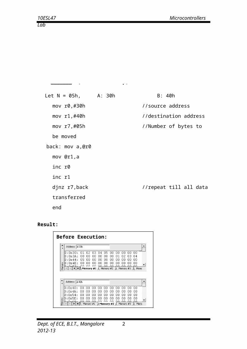
Let N = 05h, A: 30h B: 40h
mov r0,#30h //source address
mov r1,#40h //destination address
mov r7,#05h //Number of bytes to be moved
back: mov a,@r0
mov @r1,a
inc r0
inc r1
djnz r7,back //repeat till all data transferred
end
Result:
2. Write an assembly language program to exchange N = ___h bytes of data at location A : _____h and at location B : _____h.
Dept. of ECE, B.I.T., Mangalore 2012-13 2
Before Execution:
After Execution:

10ESL47 Microcontrollers Lab
Let N = 05h, A: 30h, B: 40h
mov r0,#30h //source address
mov r1,#40h //destination address
mov r7,#05h //count, the number of data to be exchanged
back: mov a,@r0
mov r4,a
mov a,@r1
mov @r0,a
mov a,r4
mov @r1,a
inc r0
inc r1
djnz r7,back
end
Result:
Dept. of ECE, B.I.T., Mangalore 2012-13 3
Before Execution:
After Execution:

10ESL47 Microcontrollers Lab
3. Write an assembly language program to find the largest element in a given array of N =___ h bytes at location 9000h. Store the largest element at location 4062h.
Let N = 06h
mov r3,#6 //length of the array mov dptr,#4000H //starting address of array movx a,@dptr mov r1,a
nextbyte: inc dptr movx a,@dptr clr c //reset borrow flag mov r2,a //next number in the array subb a,r1 //other Num-Prev largest no. jc skip // JNC FOR SMALLEST ELEMENT mov a,r2 //update larger number in r1 mov r1,a
skip: djnz r3,nextbyte mov dptr, #4062H //location of the result-4062h mov a,r1 //largest number movx @dptr,a //store at #4062H end
Result:
Before Execution:
After Execution:
Dept. of ECE, B.I.T., Mangalore 2012-13 4

10ESL47 Microcontrollers Lab
4. Write an assembly language program to sort an array of N =____ h bytes of data in ascending/descending order stored from location 9000h. (Using bubble sort algorithm)
Let N = 06h
mov R0,#05H //count (N-1) array size = N loop1:mov dptr, #9000h //array stored from address 9000h
mov r1,#05h //initialize exchange counter loop2:movx a, @dptr //get number from array and store in B register
mov b, a inc dptrmovx a, @dptr //next number in the arrayclr c //reset borrow flagmov r2, a //store in R2subb A, b //2nd-1st No.,since no compare instruction in 8051jnc noexchg // JC - FOR DESCENDING ORDERmov a,b //exhange the 2 noes in the arraymovx @dptr,adec dpl //DEC DPTR - instruction not presentmov a,r2movx @dptr,ainc dptr
noexchg: djnz r1,loop2 //decrement compare counterdjnz r0,loop1 //decrement pass counter
end
Result:
Before Execution:
After Execution :( Ascending order)
Note :
Analyze the bubble sort algorithm for the given data. Also try with different sorting algorithms.
Dept. of ECE, B.I.T., Mangalore 2012-13 5

10ESL47 Microcontrollers Lab
5. Write an assembly language program to perform the addition of two 16-bit numbers.
mov r0,#34h //lower nibble of No.1 1 2 3 4mov r1,#12h //higher nibble of No.1 +f e d cmov r2,#0dch //lower nibble of No.2 -----------mov r3,#0feh //higher nibble of No.2 1 1 1 1 0clr c // -----------mov a,r0add a,r2mov 22h,amov a,r1addc a,r3mov 21h,amov 00h,cend
Result:
Dept. of ECE, B.I.T., Mangalore 2012-13 6

10ESL47 Microcontrollers Lab
6. Write an assembly language program to perform the subtraction of two 16-bit numbers.
mov r0,#0dch //lower nibble of No.1 f e d cmov r1,#0feh //higher nibble of No.1 -1 2 3 4mov r2,#34h //lower nibble of No.2 ------------mov r3,#12h //higher nibble of No.2 e c a 8clr c // -------------mov a,r0subb a,r2mov 22h,amov a,r1subb a,r3mov 21h,amov 00h,cend
Result:
Note: Try with different data. Ex: (Smaller number) – (larger number).
Dept. of ECE, B.I.T., Mangalore 2012-13 7

10ESL47 Microcontrollers Lab
7. Write an assembly language program to perform the multiplication of two 16-bit numbers.
mov r0,#34h // 5678*1234mov r1,#12hmov r2,#78hmov r3,#56hmov a,r0mov b,r2mul abmov 33h,amov r4,bmov a,r0mov b,r3mul abadd a,r4mov r5,amov a,baddc A,#00hmov r6,amov a,r1mov b,r2mul abadd a,r5mov 32h,amov a,baddc a,r6mov 00h,cmov r7,amov a,r3mov b,r1mul abadd a,r7mov 31h,amov a,baddc A,20hmov 30h,aend
Result:
Note: Write the logic of the program. Try with some other logic.
Dept. of ECE, B.I.T., Mangalore 2012-13 8

10ESL47 Microcontrollers Lab
8. Write an assembly language program to find the square of a given number N.
Let N = 05
mov a,#05 // a=N=05mov b,amul abmov 30h,a // result is stored in 30h and 31hmov 31h,bend
Result:
Input: Output:
9. Write an assembly language program to find the cube of a given number.
mov r0,#0fh // ro=given number to find the cube of it.mov a,r0mov b,r0mul abmov r1,bmov b,r0mul abmov 32h,amov r2,bmov a,r1mov b,r0mul abadd a,r2mov 31h,amov a,baddc A,#00hmov 30h,a //result is stored in 30h, 31h, 32hend
Result:
Input: Output:
Dept. of ECE, B.I.T., Mangalore 2012-13 9

10ESL47 Microcontrollers Lab
10. Write an ALP to compare two eight bit numbers NUM1 and NUM2 stored in external memory locations 8000h and 8001h respectively. Reflect your result as: If NUM1<NUM2, SET LSB of data RAM location 2FH (bit address 78H). If NUM1>NUM2, SET MSB of location 2FH (bit address 7FH). If NUM1 = NUM2, then Clear both LSB & MSB of bit addressable memory location 2FH.
mov dptr,#8000hmovx a,@dptrmov r0,ainc dptrmovx a,@dptrclr csubb a,r0jz equaljnc smallsetb 7fhsjmp end1
small:setb 78hsjmp end1
equal: clr 78hclr 7fh
end1: end
Result :
1) Before Execution: X: 8000h = & X: 8001 = After Execution: D: 02FH =2) Before Execution: X: 8000h = & X: 8001 = After Execution: D: 02FH =3) Before Execution: X: 8000h = & X: 8001 = After Execution: D: 02FH =
11. Write an assembly language program to count number of ones and zeros in a eight bit number.
mov r1,#00h // to count number of 0smov r2,#00h // to count number of 1smov r7,#08h // counter for 8-bitsmov a,#97h // data to count number of 1s and 0s
again: rlc ajc next
inc r1sjmp here
next: inc r2here: djnz r7,again
end
]Result:Input: Output: Number of zero’s = r2 =
Number of one’s = r1 =
Dept. of ECE, B.I.T., Mangalore 2012-13 10

10ESL47 Microcontrollers Lab
12. Write an assembly language program to find whether given eight bit number is odd or even. If odd store 00h in accumulator. If even store FFh in accumulator.**
mov a,20h // 20h=given number, to find is it even or oddjb acc.0, oddmov a,#0FFhsjmp ext
odd: mov a,#00h ext: end
Result:
Input: Output:20h: a:
13. Write an assembly language program to perform logical operations AND, OR, XOR on two eight bit numbers stored in internal RAM locations 21h, 22h.
MOV A, 21H //do not use #, as data ram 21h is to be accessedANL A, 22H //logical AND operationMOV 30H, A //AND operation result stored in 30hMOV A, 21HORL A, 22H //logical OR operationMOV 31H, A //OR operation result stored in 31hMOV A, 21HXRL A, 22H //logical XOR operationMOV 32H,A // XOR operation result stored in 32h
END
Result:
1) Before Execution: D: 21H = 22H =
After Execution: D: 030H = //AND operation
D: 031H = //OR operation
D: 032H = //XRL operation
Dept. of ECE, B.I.T., Mangalore 2012-13 11

10ESL47 Microcontrollers Lab
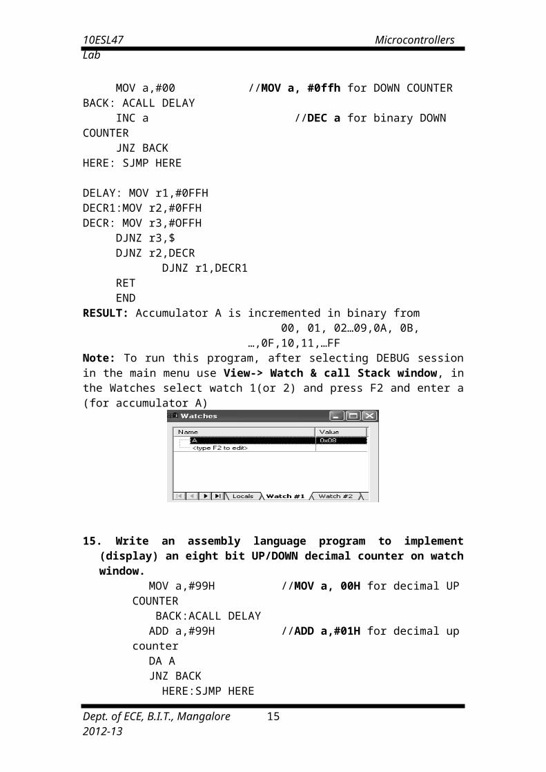
14. Write an assembly language program to implement (display) an eight bit UP/DOWN binary (hex) counter on watch window.
MOV a,#00 //MOV a, #0ffh for DOWN COUNTERBACK: ACALL DELAY
INC a //DEC a for binary DOWN COUNTERJNZ BACK
HERE: SJMP HERE
DELAY: MOV r1,#0FFHDECR1:MOV r2,#0FFHDECR: MOV r3,#OFFH
DJNZ r3,$DJNZ r2,DECR
DJNZ r1,DECR1RETEND
RESULT: Accumulator A is incremented in binary from 00, 01, 02…09,0A, 0B,…,0F,10,11,…FF
Note: To run this program, after selecting DEBUG session in the main menu use View-> Watch & call Stack window, in the Watches select watch 1(or 2) and press F2 and enter a (for accumulator A)
15. Write an assembly language program to implement (display) an eight bit UP/DOWN decimal counter on watch window.
MOV a,#99H //MOV a, 00H for decimal UP COUNTER BACK:ACALL DELAY
ADD a,#99H //ADD a,#01H for decimal up counter DA AJNZ BACK
HERE:SJMP HERE DELAY:MOV r1,#0FFH DECR1:MOV r2,#0FFH DECR:MOV r3, #0FFH
DJNZ r3,$DJNZ r2, DECRDJNZ r1, DECR1RETEND
RESULT: Accumulator A is incremented in BCD from 99,98,97,……….,00.
**Note: Show the Delay Calculations and measure on the system.
Dept. of ECE, B.I.T., Mangalore 2012-13 12

10ESL47 Microcontrollers Lab
16. Write an assembly language program to convert a BCD number into ASCII.
mov a, #09h //the BCD number to be converted to ASCIImov r0,aswap amov dptr,#9000h // output will be in 9000h and 90001hacall asciimov a,r0acall asciisjmp $
ascii: anl a,#0fhadd a,#30hmovx @dptr,ainc dptrretend
Result:
17. a. Write an assembly language program to convert a ASCII number into Decimal.
mov dptr,#9000h //ASCII number to be converted to decimal is stored in // 9000h
movx a,@dptr subb a,#30h
mov 50h,aend //Converted decimal data will be in 50h
Result:
Input: 9000h: Output: 50h:
17.b. Write an assembly language program to convert a decimal number into ASCII.
mov dptr,#9000h //Decimal number to be converted to ASCII is store inmovx a,@dptr // 9000hadd a,#30hmov dptr,#9002 // ASCII will be saved in 9002hmovx @dptr,aend
Result: Input: Output:
Dept. of ECE, B.I.T., Mangalore 2012-13 13
10ESL47 Microcontrollers Lab
18. a. Write an assembly language program to convert a binary (hex) number into decimal.
mov a,#0feh //binary number to be converted to decimalmov b,#0ahdiv abmov r0,bmov b,#0ahdiv abmov 30h,a
mov a,b swap A orl a,r0 mov 31h,A end
Result:
Input: Output:
18.b. Write an assembly language program to convert a decimal number into binary(hex).
mov a,#95h //a = Decimal number to be converted to the binary mov b,#10hdiv abmov r1,bmov b,#0ahmul abadd a,r1mov 30h,aend
Result:
Input: Output:
Dept. of ECE, B.I.T., Mangalore 2012-13 14
10ESL47 Microcontrollers Lab
19. Conduct an experiment to configure 8051 microcontroller to transmit characters “MICROCONTROLLERS LAB BIT” to a PC using the serial port and display on the serial window. ******
Note: To use result of this program, after selecting DEBUG session in the main menu use View-> serial window #1. On running & halting the program, the data is seen in the serial window.
mov tmod,#20h //setting Timer-1 in mode-2mov scon,#70hmov th1,#-3setb tr1
again: mov r0,#03hmov dptr,#8000h
nextchar: movx a,@dptracall transferinc dptrdjnz r0,nextcharsjmp again
transfer: mov sbuf,await: jnb ti,wait
clr tiretend
RESULT:
MICROCONTROLLERS LAB BIT is printed on the serial window each time the program is executed.
Theory:
In serial transmission as opposed to parallel transmission, one bit at a time is transmitted. In serial asynchronous transmission, the data consists of a Start bit (high), followed by 8 bits of data to be transmitted and finally the stop bit. The byte character to be transmitted is written into the SBUF register. It transmits the start bit. The 8-bit character is transferred one bit at a time. The stop bit is transferred. After the transmission, the TI flag = 1 indicating the completion of transmission. Hence in the subroutine wait until TI is set. Later clear the TI flag and continue with transmission of the next byte by writing into the SBUF register. (The program can also be written in interrupt mode). The speed of the serial transmission is set by the baud rate which is done with the help of timer 1. Timer1 must be programmed in mode 2 (that is, 8-bit, auto reload).Baud rate Calculation: Crystal freq/ (12*32) = (11.0592MHz)/(12*32) = 28800.Serial communication circuitry divides the machine cycle frequency (11.0592MHz)/(12) by 32 before it is being used by the timer to set the baud rate.To get 9600, 28800/3 is obtained by loading timer1 with -3 (i.e., FF – 3 = FD) for further clock division. For 2400 baud rate, 28800/12 => -12 = F4 in TH1.
Dept. of ECE, B.I.T., Mangalore 2012-13 15

10ESL47 Microcontrollers Lab
20. Conduct an experiment to generate 1second delay continuously using on chip timer.
mov tmod,#02hmov th0,#00hclr P1.0clr asetb tr0
again: mov r7,#0ffhloop: mov r6,#14dwait: jnb tf0, wait
clr tf0djnz r6,waitdjnz r7,loopcpl P1.0sjmp againend
RESULT:
Accumulator A is incremented in binary from 00, 01,02…09,0A, 0B, …, 0F, 10, 11, …FF every 1 second (for 33MHz clock setting & every 3 seconds for 11.0598MHz)
Dept. of ECE, B.I.T., Mangalore 2012-13 16

10ESL47 Microcontrollers Lab
II. Programming Using MSP430
Dept. of ECE, B.I.T., Mangalore 2012-13 17

10ESL47 Microcontrollers Lab
21. Write an assembly language program to transfer N = ___ bytes of data from location A:_______h to location B:_______h (without overlap).
A=0x8000, B=0x9000, N=5
#include "msp430.h" ; #define controlled include file NAME main ; module name PUBLIC main ; make the main label visible outside this module ORG 0FFFEh DC16 init ; set reset vector to 'init' label RSEG CSTACK ; pre-declaration of segment RSEG CODE ; place program in 'CODE' segmentinit: MOV #SFE(CSTACK), SP ; set up stackmain: NOP ; main program MOV.W #WDTPW+WDTHOLD,&WDTCTL ; Stop watchdog timer MOV.W #0x8000, R5 MOV.W #0x9000,R6 MOV.B #5,R7again: MOV.W @R5+,0(R6) INCD.W R6 DEC R7 JNZ again JMP $ END
Result:
Input:
Output:
Dept. of ECE, B.I.T., Mangalore 2012-13 18

10ESL47 Microcontrollers Lab
22. Write an assembly language program to exchange N = ___h bytes of data at location A : _____h and at location B : _____h.
A=0x8000, B=0x9000, N=5
#include "msp430.h" ; #define controlled include file NAME main ; module name PUBLIC main ; make the main label visible outside this module ORG 0FFFEh DC16 init ; set reset vector to 'init' label RSEG CSTACK ; pre-declaration of segment RSEG CODE ; place program in 'CODE' segmentinit: MOV #SFE(CSTACK), SP ; set up stackmain: NOP ; main program MOV.W #WDTPW+WDTHOLD,&WDTCTL ; Stop watchdog timer
MOV.W #0x8000, R5 MOV.W #0x9000,R6 MOV.B #5,R7again: MOV.W @R5,R8 MOV.W @R6,0(R5) MOV.W R8,0(R6) INCD.W R6 INCD.W R5 DEC R7 JNZ again JMP $ END
Result: Input: Output:
Dept. of ECE, B.I.T., Mangalore 2012-13 19

10ESL47 Microcontrollers Lab
23. Write an assembly language program to perform the addition of two 32-bit numbers.
#include "msp430.h" ; #define controlled include file NAME main ; module name PUBLIC main ; make the main label visible outside this module ORG 0FFFEh DC16 init ; set reset vector to 'init' label RSEG CSTACK ; pre-declaration of segment RSEG CODE ; place program in 'CODE' segmentinit: MOV #SFE(CSTACK), SP ; set up stackmain: NOP ; main program MOV.W #WDTPW+WDTHOLD,&WDTCTL ; Stop watchdog timer
MOV.W #0X9000,R4 //NUM1:FFFF9000 MOV.W #0XFFFF,R7 //NUM2:FFFFFFFF ADD.W R4,R7 MOV.W #0XFFFF,R5 MOV.W #0XFFFF,R6 ADDC R5,R6
JMP $ ENDResult:
Input: Output:
24. Write an assembly language program to perform the subtraction of two 32-bit numbers.
#include "msp430.h" ; #define controlled include file NAME main ; module name PUBLIC main ; make the main label visible outside this module ORG 0FFFEh DC16 init ; set reset vector to 'init' label RSEG CSTACK ; pre-declaration of segment RSEG CODE ; place program in 'CODE' segmentinit: MOV #SFE(CSTACK), SP ; set up stackmain: NOP ; main program MOV.W #WDTPW+WDTHOLD,&WDTCTL ; Stop watchdog timer
MOV.W #0X9000,R4 MOV.W #0XFFFF,R7 SUB.W R4,R7 MOV.W #0XFFFF,R5 MOV.W #0XFFFF,R6 SUBC R5,R6 JMP $ END Result:
Input: Output:
Dept. of ECE, B.I.T., Mangalore 2012-13 20

10ESL47 Microcontrollers Lab
25. Write an assembly language program to perform the multiplication of two 16-bit numbers.
#include "msp430.h" ; #define controlled include file NAME main ; module name PUBLIC main ; make the main label visible outside this module ORG 0FFFEh DC16 init ; set reset vector to 'init' label RSEG CSTACK ; pre-declaration of segment RSEG CODE ; place program in 'CODE' segmentinit: MOV #SFE(CSTACK), SP ; set up stackmain: NOP ; main program MOV.W #WDTPW+WDTHOLD,&WDTCTL ; Stop watchdog timer
MOV.W #0XFFFF, R4 ; R4= FFFF MOV.W R4, R8 MOV.W #0X1234, R7 ; R7= 1234, (FFFF x 1234) MOV.W #00, R5 MOV.W #00, R10 ; PRODUCT LOWER 16 BIT (DB98) MOV.W #00, R9 ; PRODUCT UPPER 16 BIT (1233) CLRC INC.W R5
UP: ADD.W R4, R8 ; SUCCESSIVE ADDITION JNC COPY INC.W R9
COPY:INC.W R5 CLRC CMP.W R5, R7 JNE UP MOV.W R8, R10 JMP $ ; (endless loop)
END
Result: Input: Output:
Note: For square of a number give both the numbers same value. Assignment: Find the cube of a number.
Dept. of ECE, B.I.T., Mangalore 2012-13 21

10ESL47 Microcontrollers Lab
26. Write an assembly language program to perform the division of two 16-bit numbers.
#include "msp430.h" ; #define controlled include file NAME main ; module name PUBLIC main ; make the main label visible outside this module ORG 0FFFEh DC16 init ; set reset vector to 'init' label RSEG CSTACK ; pre-declaration of segment RSEG CODE ; place program in 'CODE' segmentinit: MOV #SFE(CSTACK), SP ; set up stackmain: NOP ; main program MOV.W #WDTPW+WDTHOLD,&WDTCTL ; Stop watchdog timer
MOV.W #0XFFFF, R4 ; 16 BIT DIVIDEND MOV.W #0XAA01, R7 ; 16 BIT DIVISOR (FFFF/AA01) MOV.W #00, R5 MOV.W #00, R9 ; R9 IS QUOTIENT CLRC ; Clear Carry FlagUP: MOV.W R4, R10 ; R10 IS REMAINDER SUB.W R7, R4 ; SUCCESSIVE SUBSTRACTION JNC DONE INC.W R9 COPY: CMP.W R5, R4 JNZ UPDONE: JMP $ ; (endless loop) END
Result: Input: Output:
Dept. of ECE, B.I.T., Mangalore 2012-13 22

10ESL47 Microcontrollers Lab
27. Write an assembly language program to sort an array of N =____ h bytes of data in ascending/descending order stored from location 9000h.(use bubble sort algorithm)
#include "msp430.h" ; #define controlled include file NAME main ; module name PUBLIC main ; make the main label visible outside this module ORG 0FFFEh DC16 init ; set reset vector to 'init' label RSEG CSTACK ; pre-declaration of segment RSEG CODE ; place program in 'CODE' segmentinit: MOV #SFE(CSTACK), SP ; set up stackmain: NOP ; main program MOV.W #WDTPW+WDTHOLD,&WDTCTL ; Stop watchdog timer
MOV.W #04,R4 ; count (N-1) ARRAY SIZE=N UP: MOV.W #0x9000,R10 ;array stored from address 9000h
MOV.W #00,R11 MOV.W R4, R5 ; initialize exchange counter
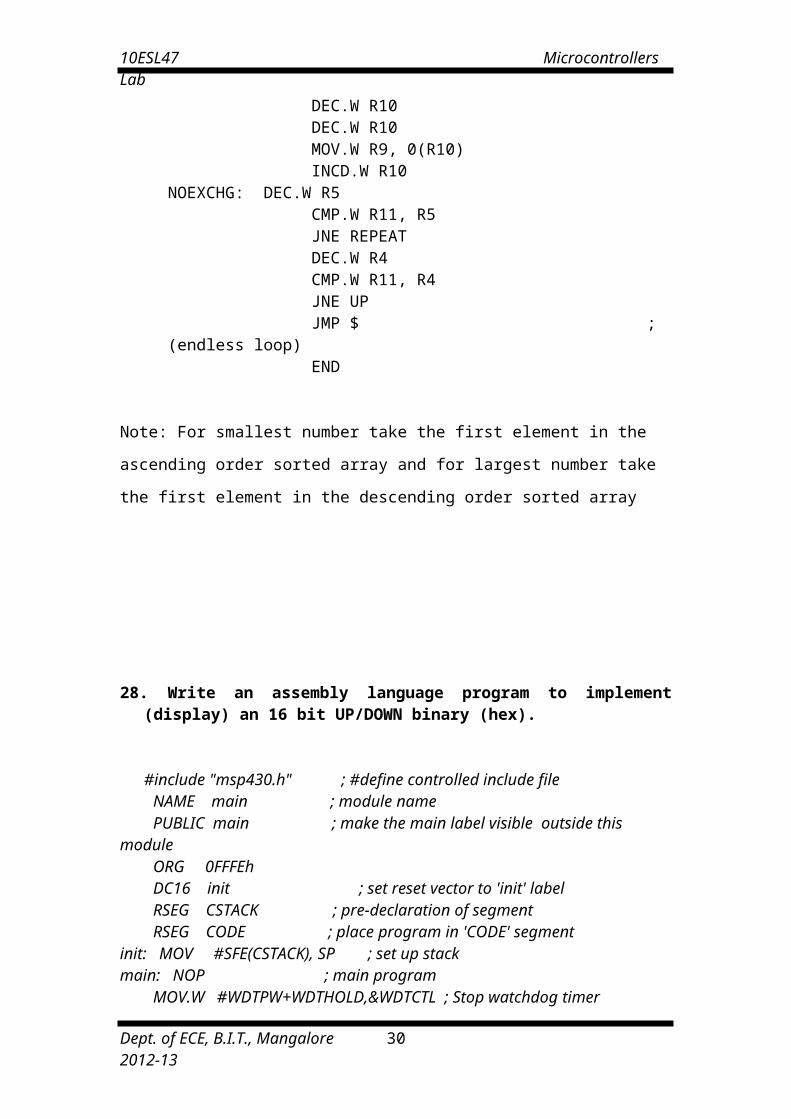
REPEAT: MOV.W @R10+, R6 ; Get 1st Number from Array MOV.W R6, R8 MOV.W @R10, R7 ; Get 2nd Number from Array MOV.W R7, R9 SUB.W R7, R6 JNC NOEXCHG ; JC - FOR DESCENDING ORDER MOV.W R8, 0(R10) ; //Exchange The 2 No’s In The Array DEC.W R10 DEC.W R10 MOV.W R9, 0(R10) INCD.W R10
NOEXCHG: DEC.W R5 CMP.W R11, R5 JNE REPEAT DEC.W R4 CMP.W R11, R4 JNE UP JMP $ ; (endless loop) END
Note: For smallest number take the first element in the ascending order sorted array
and for largest number take the first element in the descending order sorted array
Dept. of ECE, B.I.T., Mangalore 2012-13 23

10ESL47 Microcontrollers Lab
28. Write an assembly language program to implement (display) an 16 bit UP/DOWN binary (hex).
#include "msp430.h" ; #define controlled include file NAME main ; module name PUBLIC main ; make the main label visible outside this module ORG 0FFFEh DC16 init ; set reset vector to 'init' label RSEG CSTACK ; pre-declaration of segment RSEG CODE ; place program in 'CODE' segmentinit: MOV #SFE(CSTACK), SP ; set up stackmain: NOP ; main program MOV.W #WDTPW+WDTHOLD,&WDTCTL ; Stop watchdog timer
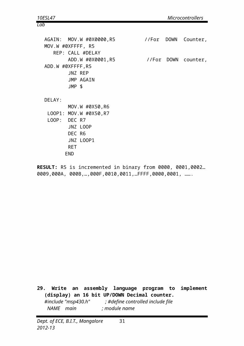
AGAIN: MOV.W #0X0000,R5 //For DOWN Counter, MOV.W #0XFFFF, R5 REP: CALL #DELAY ADD.W #0X0001,R5 //For DOWN counter, ADD.W #0XFFFF,R5 JNZ REP JMP AGAIN JMP $
DELAY: MOV.W #0X50,R6 LOOP1: MOV.W #0X50,R7 LOOP: DEC R7 JNZ LOOP DEC R6 JNZ LOOP1 RET END
RESULT: R5 is incremented in binary from 0000, 0001,0002…0009,000A, 000B,…,000F,0010,0011,…FFFF,0000,0001, …….
Dept. of ECE, B.I.T., Mangalore 2012-13 24
10ESL47 Microcontrollers Lab
29. Write an assembly language program to implement (display) an 16 bit UP/DOWN Decimal counter. #include "msp430.h" ; #define controlled include file
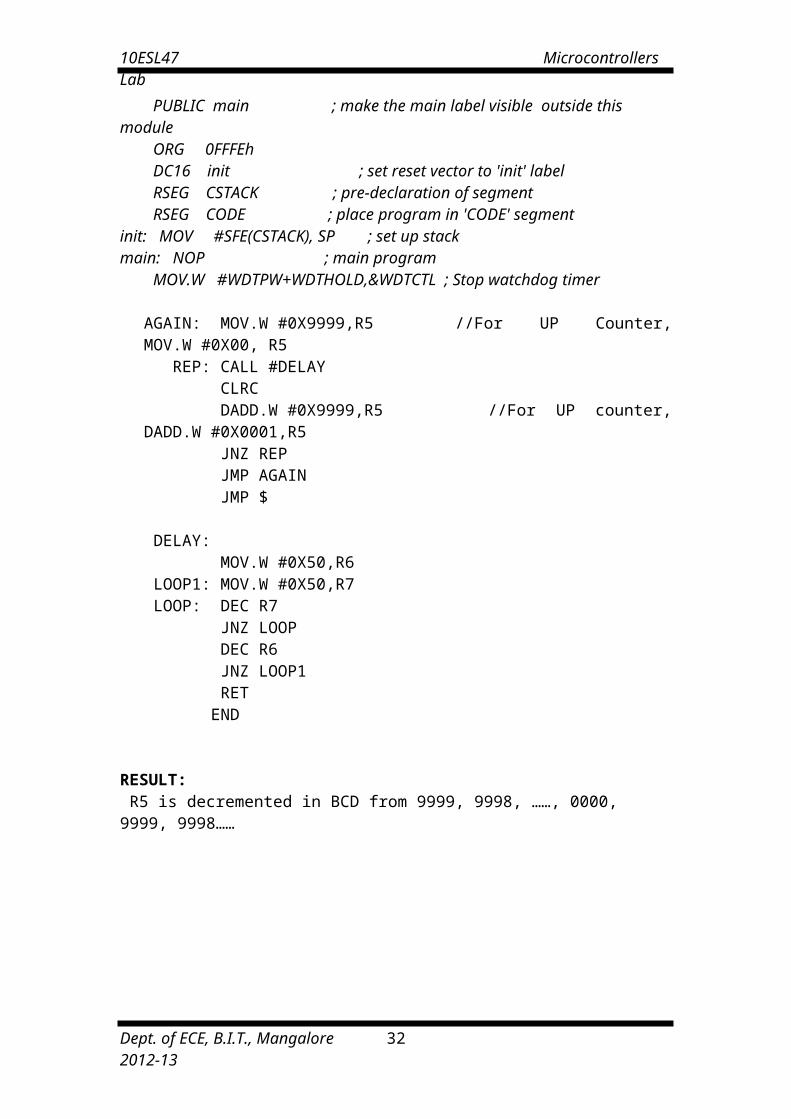
NAME main ; module name PUBLIC main ; make the main label visible outside this module ORG 0FFFEh DC16 init ; set reset vector to 'init' label RSEG CSTACK ; pre-declaration of segment RSEG CODE ; place program in 'CODE' segmentinit: MOV #SFE(CSTACK), SP ; set up stackmain: NOP ; main program MOV.W #WDTPW+WDTHOLD,&WDTCTL ; Stop watchdog timer
AGAIN: MOV.W #0X9999,R5 //For UP Counter, MOV.W #0X00, R5 REP: CALL #DELAY CLRC DADD.W #0X9999,R5 //For UP counter, DADD.W #0X0001,R5 JNZ REP JMP AGAIN JMP $ DELAY: MOV.W #0X50,R6 LOOP1: MOV.W #0X50,R7 LOOP: DEC R7 JNZ LOOP DEC R6 JNZ LOOP1 RET END
RESULT: R5 is decremented in BCD from 9999, 9998, ……, 0000, 9999, 9998……
Dept. of ECE, B.I.T., Mangalore 2012-13 25

10ESL47 Microcontrollers Lab
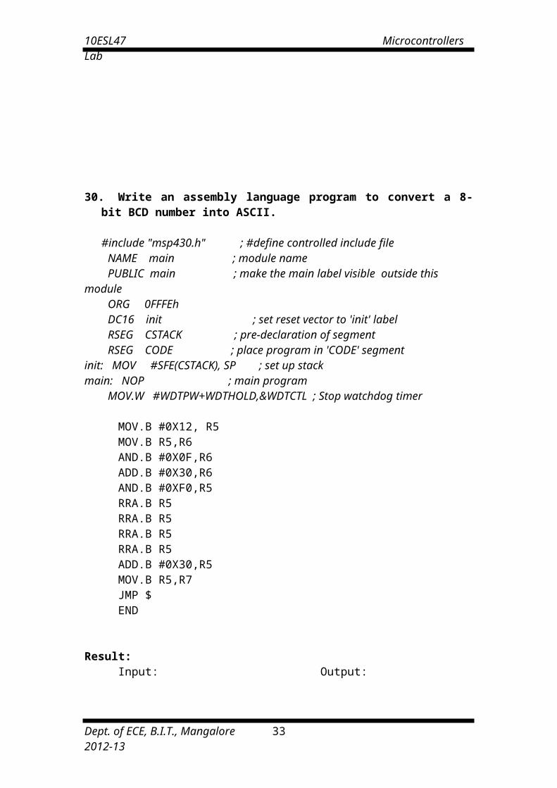
30. Write an assembly language program to convert a 8-bit BCD number into ASCII.
#include "msp430.h" ; #define controlled include file NAME main ; module name PUBLIC main ; make the main label visible outside this module ORG 0FFFEh DC16 init ; set reset vector to 'init' label RSEG CSTACK ; pre-declaration of segment RSEG CODE ; place program in 'CODE' segmentinit: MOV #SFE(CSTACK), SP ; set up stackmain: NOP ; main program MOV.W #WDTPW+WDTHOLD,&WDTCTL ; Stop watchdog timer
MOV.B #0X12, R5 MOV.B R5,R6 AND.B #0X0F,R6 ADD.B #0X30,R6 AND.B #0XF0,R5 RRA.B R5 RRA.B R5 RRA.B R5 RRA.B R5 ADD.B #0X30,R5 MOV.B R5,R7 JMP $ END
Result: Input: Output:
Dept. of ECE, B.I.T., Mangalore 2012-13 26

10ESL47 Microcontrollers Lab
31. A. Write an assembly language program to convert a ASCII number into Decimal.
#include "msp430.h" ; #define controlled include file NAME main ; module name PUBLIC main ; make the main label visible outside this module ORG 0FFFEh DC16 init ; set reset vector to 'init' label RSEG CSTACK ; pre-declaration of segment RSEG CODE ; place program in 'CODE' segmentinit: MOV #SFE(CSTACK), SP ; set up stackmain: NOP ; main program MOV.W #WDTPW+WDTHOLD,&WDTCTL ; Stop watchdog timer
MOV.B #0X35, R5 SUB.B #0X30,R5 MOV.B R5,R6 JMP $ END
Result:
Input: Output:
31. B. Write an assembly language program to convert a Decimal number into ASCII.
#include "msp430.h" ; #define controlled include file NAME main ; module name PUBLIC main ; make the main label visible outside this module ORG 0FFFEh DC16 init ; set reset vector to 'init' label RSEG CSTACK ; pre-declaration of segment RSEG CODE ; place program in 'CODE' segmentinit: MOV #SFE(CSTACK), SP ; set up stackmain: NOP ; main program MOV.W #WDTPW+WDTHOLD,&WDTCTL ; Stop watchdog timer
MOV.B #0X05, R5 ADD.B #0X30,R5 MOV.B R5,R6 JMP $ END
Result:
Input: Output:
Dept. of ECE, B.I.T., Mangalore 2012-13 27

10ESL47 Microcontrollers Lab
32. A. Write an assembly language program to convert a binary (hex) number into decimal.
#include "msp430.h" ; #define controlled include file NAME main ; module name PUBLIC main ; make the main label visible outside this module ORG 0FFFEh DC16 init ; set reset vector to 'init' label RSEG CSTACK ; pre-declaration of segment RSEG CODE ; place program in 'CODE' segmentinit: MOV #SFE(CSTACK), SP ; set up stackmain: NOP ; main program MOV.W #WDTPW+WDTHOLD,&WDTCTL ; Stop watchdog timer MOV.B #0XFE,R5 MOV.B #0X0A,R6 CALL #AA MOV.B R5,R9 MOV.B R7,R5 CALL #AA AND.W #0X00FF,R7 SWPB R7 RLA.B R5 RLA.B R5 RLA.B R5 RLA.B R5 ADD.W R5,R7 ADD.W R9,R7 JMP $ AA: MOV.B #0XFF,R7LOOP: INC R7 SUB.B R6,R5 JC LOOP ADD.W #0x0A,R5 RET END
Result:
Input: Output:
Dept. of ECE, B.I.T., Mangalore 2012-13 28

10ESL47 Microcontrollers Lab
32. B. Write an assembly language program to convert a decimal number into binary(hex).
#include "msp430.h" ; #define controlled include file NAME main ; module name PUBLIC main ; make the main label visible outside this module ORG 0FFFEh DC16 init ; set reset vector to 'init' label RSEG CSTACK ; pre-declaration of segment RSEG CODE ; place program in 'CODE' segment
init: MOV #SFE(CSTACK), SP ; set up stackmain: NOP ; main program
MOV.W #WDTPW+WDTHOLD,&WDTCTL ; Stop watchdog timer
MOV.B #0X99,R5 MOV.B #0X10,R6 MOV.B #0XFF,R7LOOP: INC R7 SUB.B R6,R5 JC LOOP ADD.B #0x10,R5 AND.W #0X00FF,R7 MOV.B #0X00,R8AGAIN:ADD.B #0X0A,R8 DEC R7 JNZ AGAIN ADD.B R5,R8 JMP $ END
Result:
Input: Output:
Dept. of ECE, B.I.T., Mangalore 2012-13 29
10ESL47 Microcontrollers Lab
33. Write an assembly language program to perform logical operations AND, OR, XOR on two 16 bit numbers.
#include "msp430.h" ; #define controlled include file NAME main ; module name PUBLIC main ; make the main label visible outside this module ORG 0FFFEh DC16 init ; set reset vector to 'init' label RSEG CSTACK ; pre-declaration of segment RSEG CODE ; place program in 'CODE' segment
init: MOV #SFE(CSTACK), SP ; set up stackmain: NOP ; main program
MOV.W #WDTPW+WDTHOLD,&WDTCTL ; Stop watchdog timer
MOV.W #0X1234, R5 MOV.W #0XABCD,R6 MOV.W R6,R7 MOV.W R6,R8 AND.W R5,R6 //R6=R5 AND R6 XOR.W R5,R7 //R7=R5 XOR R7 INV.W R8 //R8=NOT R8 INV.W R5 AND.W R8,R5 INV.W R5 //R5=R8 OR R5 JMP $ END
Dept. of ECE, B.I.T., Mangalore 2012-13 30
10ESL47 Microcontrollers Lab
III. Interfacing
Dept. of ECE, B.I.T., Mangalore 2012-13 31
10ESL47 Microcontrollers Lab
34. a. Write a C program to generate square wave of amplitude ___ V of frequency _________Hz using DAC. Display the waveform on the CRO.
35. a. Write a C program to generate square wave of amplitude ___ V of frequency _________Hz using DAC. Display the waveform on the CRO.
Circuit Diagram for wave form generation:
Dept. of ECE, B.I.T., Mangalore 2012-13 32
8 0 5 1
U5
U3
DAC0800
Ch1
CRO
Ch2
P0.0..
P0.7
P1.0..
P1.7
B1..
B8
DAC0800
B1..
B8
Yout
Xout
Dual DAC
10ESL47 Microcontrollers Lab
Program:#include <REG51xD2.H>void delay(unsigned int x) /* delay routine */{ for(;x>0;x--);}
main(){ unsigned char on = 0x7f,off=0x00; unsigned int fre = 230; while(1) { P0=P1=on; /* write apmlitude to port */ delay(fre); P0=P1=off; /* clear port */ delay(fre);
}}
DESIGN:
Let f = 2 kHz, Therefore T = 1/f= 0.5msec, Count value for the delay is (T/ 1clock cycle period) = 0.5 x 10⁻³sec/1.085 x 10-6secHence Count value is =460. Hence for 50% Duty cycle the Count value is half of the Count value=230.Note: Delay produced by the program will depend on the microcontroller you are using, so frequency of the waveform generated may not match with the given frequency.
34. b. Write a C program to generate ramp wave of amplitude ___ V using DAC. Display the waveform on the CRO. Program:
#include <REG51xD2.H>main(){unsigned char amp = 0xff;unsigned char i=0; P0=P1=0x00; /* P0 as Output port */ while(1) { { for(i=0;i<amp;i++) /* Generate ON pulse */ P0=P1=i; } }}34.c. Write a C program to generate triangular wave of amplitude ___ V using
Dept. of ECE, B.I.T., Mangalore 2012-13 33

10ESL47 Microcontrollers Lab
DAC. Display the waveform on the CRO. Program: #include <REG51xD2.H>main(){ unsigned char i=0; P0=P1=0x00; /* P0 as Output port */ while(1) { for(i=0x00;i<0xff;i++) /* Generate ON pulse */ P0=P1=i; for(i=0xff;i>0x00;i--) /* Generate OFF pulse */ P0=P1=i; }}
34.d Program for dual DAC interfacing to generate sine waveform.
To generate a sine wave, we first need a table whose values represent the
magnitude of the sine of angles between 0 360 degrees. The values for the sine
function vary form -1.0 to +1.0 for 0- to 360- degree angles. Therefore, the table
values are integer numbers representing the voltage magnitude for the sine of theta.
This method ensures that only integer numbers are output to the DAC by the 8051
microcontroller. Table below shows the angles, the sine values, the voltage
magnitudes, and the integer values representing the voltage magnitude for each angle.
To generate table, we assumed the full-scale voltage of 10 V for DAC output. Full-
scale output of the DAC is achieved when all the data inputs of the DAC are high.
Therefore, to achieve the full-scale 10 V output, we use following equation.
Vout=5V+(5V*Sinθ)
Angle ‘θ’ in degrees
Sinθ Vout=5V+(5V*Sinθ)Values sent to
DAC(decimal) Vout*25.6010.......
350360
Program:
Dept. of ECE, B.I.T., Mangalore 2012-13 34

10ESL47 Microcontrollers Lab
#include <REG51xD2.H>void main(){unsigned char i,wave[36]={128,148,171,192,209,225,238,245,253,255,253, 245,238,225,209,192,171,128,104,82,64,43,28,15,07,01,00,01,07,15,28,43,64,82,104};P0 = 0x00;while(1){for (i=0; i<36; i++) P0=P1=wave[i];}}
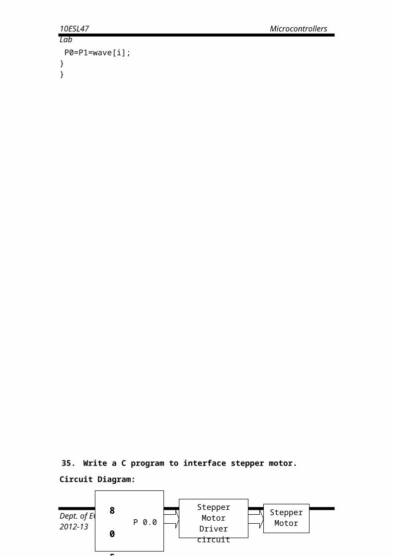
35. Write a C program to interface stepper motor.
Dept. of ECE, B.I.T., Mangalore 2012-13 35

10ESL47 Microcontrollers Lab
Circuit Diagram:
Theory:
Stepper motor is an electromechanical device which converts electrical pulses into discrete mechanical movements. The shaft or spindle of a stepper motor rotates in discrete step increments when electrical command pulses are applied to it in the proper sequence. The motors rotation has several direct relationships to these applied input pulses. The sequence of the applied pulses is directly related to the direction of motor shafts rotation. The speed of the motor shafts rotation is directly related to the frequency of the input pulses and the length of rotation is directly related to the number of input pulses applied.
Stepper Motor Advantages:
1. The rotation angle of the motor is proportional to the input pulse. 2. The motor has full torque at standstill (if the windings are energized)3. Precise positioning and repeatability of movement since good stepper motors have an accuracy of 3 – 5% of a step and this error is non cumulative from one step to the next.4. Excellent response to starting/stopping/reversing.5. Very reliable since there are no contact brushes in the motor. Therefore the life of the motor is simply dependant on the life of the bearing.6. The motors response to digital input pulses provides open-loop control, making the motor simpler and less costly to control.1. It is possible to achieve very low speed synchronous rotation with a load that is
directly coupled to the shaft.2. A wide range of rotational speeds can be realized as the speed is proportional to
the frequency of the input pulses.
Stepper Motor Disadvantages:
1. Resonances can occur if not properly controlled.2. Not easy to operate at extremely high speeds.
Open Loop Operation:
One of the most significant advantages of a stepper motor is its ability to be accurately controlled in an open loop system. Open loop control means no feedback information about position is needed. This type of control eliminates the need for expensive sensing and feedback devices such as optical encoders. Your position is known simply by keeping track of the input step pulses.
Stepper Motor Types:
• Variable-reluctance • Permanent-magnet • Hybrid// Program to interface stepper motor
Dept. of ECE, B.I.T., Mangalore 2012-13 36
8 P 0.0 0 5 P 0.7 1
StepperMotor
Driver circuit
StepperMotor

10ESL47 Microcontrollers Lab
#include <REG51xD2.H>void delay (unsigned int x) /* Delay Routine */{ for(;x>0;x--); return;}main ( ){ unsigned char Val, i; P0=0x00;while(1){ Val = 0x11; for (i=0;i<4;i++)
{ P0 = Val; Val = Val<<1; /* Val= Val>>1; for clockwise direction*/ delay (500); }
}}
Motor Specifications:Step Angle = 1.8 degreesStep angle accuracy = 5%Holding Torque = 40NcmRotor Inertia = 115grcm2
Weight = 0.5KgInsulation = Class B
36. Write a C program to interface LCD and keypad
Block Diagram:
Dept. of ECE, B.I.T., Mangalore 2012-13 37

10ESL47 Microcontrollers Lab
Keyboard:
HEX values of the keys:
LABLE ON THE KEYTOP
HEX CODE
LABLE ON THE KEYTOP
HEX CODE
0 0 - 0C1 1 * 0D2 2 / 0E3 3 % 0F4 4 AC 105 5 CE 116 6 CHK 127 7 = 138 8 MC 149 9 MR 15. 0A M 16+ 0B M+ 17
Dept. of ECE, B.I.T., Mangalore 2012-13 38
8 0 5 1
LCDP1.0
.
.P1.7
KEY BOARD
P2
P0

10ESL47 Microcontrollers Lab
Program to interface LCD and KEYPAD :
#include <REG51xD2.H>#include "lcd.h"unsigned char getkey();void delay(unsigned int);main(){ unsigned char key,tmp; InitLcd(); //Initialise LCD WriteString("Key Pressed="); // Display msg on LCD while(1) { GotoXY(12,0); //Set Cursor Position key = getkey(); //Call Getkey method } } unsigned char getkey() { unsigned char i,j,k,indx,t; P2 = 0x00; //P2 as Output port
indx = 0x00;//Index for storing the 1st value of scanline for(i=1;i<=4;i<<=1) //for 4 scanlines { P2 = 0x0f & ~i; //write data to scanline t = P0; //Read readlines connected to P0 t = ~t; if(t>0) //If key press is true { delay(6000); //Delay for bouncing for(j=0;j<=7;j++) //Check for 8 lines { t >>=1; if(t==0) //if get pressed key {
k = indx+j; //Display that by converting to Asciit = k>>4; t +=0x30;
WriteChar(t); //Write upper nibble t = k & 0x0f; if(t > 9) t+=0x37; else t+=0x30; WriteChar(t); //write lower nibble return(indx+j); //Return index of the key pressed
} } } indx += 8; //If no key pressed increment index
} }void delay(unsigned int x) //Delay routine { for(;x>0;x--); }
Dept. of ECE, B.I.T., Mangalore 2012-13 39

10ESL47 Microcontrollers Lab
Additional Programs1. Program to check whether given number is palindrome or not.
mov 30h,#81hmov r0,30hmov r1,#08hmov 31h,#00hclr c
back: mov a,30hrlc amov 30h,amov a,31hrrc amov 31h,adjnz r1,backcjne a,00h,npalmov a,#0ffhsjmp next
npal: mov a,#00h next: sjmp $
end
2. Program to find the average of N eight-bit numbers.
Mov dptr, #9000hMov r0, #04hMov r1, #00hMov r2, #00hClr cMov r4, #04h
Back: mov a, @dptr Mov r3, a Inc dptr Mov a, r1 Add a, r3 Jnc ahead Inc r2Ahead: mov r1,a Djnz r0,back Mov r5, #00h Clr c Mov a,r1Again:subb a, r4 Inc r5 Jc next Sjmp againNext:cjne r2,#00,loc Dec r5
Dept. of ECE, B.I.T., Mangalore 2012-13 40
Add a,r4Movx @dptr,aMov a,r5Inc dptrMovx @dptr, aSjmp end1Loc: dec r2Sjmp againEnd1:lcall 0003hend

10ESL47 Microcontrollers Lab
3. Program to generate first ten Fibonacci numbers.Mov dptr, #9000hMov r3, #08hMovx a, @dptrMov r0,aInc dptrMovx a, @dptr
Back: xch a, r0 Add a,r0
Inc dptrMovx @dptr,aDjnz r3,backLcall 0003h
4. Program to add multibyte numbers.Mov dptr,#9000hMov r1,#04hMov r2,#90hMov r3,#91hMov r4,#92hClr cMov dph,r2Back: movx a, @dptrMov r5,aMov dph,r3Movx a,@dptrAddc a,r5 //Note:For multibyte subtraction put subb a,r5Mov dph,r4Movx @dptr,aInc dptrDjnz r1,backJnc end1Mov a,#01hMovx @dptr, aEnd1:lcall 0003hEnd
5. Program to search a key element in an array and display its position if it is found else display 00h to indicate not found.
Mov dptr,#9000hMov f0,#02Mov r1,#0aMov r2,#00Next:movx a,@dptrInc r2Cjne a,f0,downMov dpl,#50Mov a,#ffMovx @dptr,aMov a,r2Inc dptr
Dept. of ECE, B.I.T., Mangalore 2012-13 41
Movx @dptr,aSjmp end1Down:inc dptrDjnz r1,nextMov a ,#00Mov dpl,#50Movx @dptr,aEnd1:lcall 0003End

10ESL47 Microcontrollers Lab
Viva Questions
1. What do you mean by Embedded System? Give examples.2. Why are embedded Systems useful?3. What are the segments of Embedded System?4. What is Embedded Controller?5. What is Microcontroller?6. List out the differences between Microcontroller and Microprocessor.7. How are Microcontrollers more suitable than Microprocessor for Real Time
Applications?8. What are the General Features of Microcontroller?9. Explain briefly the classification of Microcontroller.10. Explain briefly the Embedded Tools.11. Explain the general features of 8051 Microcontroller.12. How many pin the 8051 has?13. Differentiate between Program Memory and Data Memory.14. What is the size of the Program and Data memory?15. Write a note on internal RAM. What is the necessity of register banks? Explain.16. How many address lines are required to address 4K of memory? Show the
necessary calculations.17. What is the function of accumulator?18. What are SFR’s? Explain briefly.19. What is the program counter? What is its use?20. What is the size of the PC?21. What is a stack pointer (SP)?22. What is the size of SP?23. What is the PSW? And briefly describe the function of its fields.24. What is the difference between PC and DPTR?25. What is the difference between PC and SP?26. What is ALE? Explain the functions of the ALE in 8051.27. Describe the 8051 oscillator and clock.28. What are the disadvantages of the ceramic resonator?29. What is the function of the capacitors in the oscillator circuit?30. Show with an example, how the time taken to execute an instruction can be
calculated.31. What is the Data Pointer register? What is its use in the 8051?32. Explain how the 8051 implement the Harvard Architecture?33. Explain briefly the difference between the Von Neumann and the Harvard
Architecture.34. Describe in detail how the register banks are organized.35. What are the bit addressable registers and what is the need?36. What is the need for the general purpose RAM area?37. Write a note on the Stack and the Stack Pointer.38. Why should the stack be placed high in internal RAM?39. Explain briefly how internal and external ROM gets accessed.40. What are the different addressing modes supported by 8051 Microcontroller ?41. Explain the Immediate Addressing Mode.42. Explain the Register Addressing Mode.43. Explain the Direct Addressing Mode.
Dept. of ECE, B.I.T., Mangalore 2012-13 42

10ESL47 Microcontrollers Lab
44. Explain the Indirect Addressing Mode.45. Explain the Code Addressing Mode.46. Explain in detail the Functional Classification of 8051 Instruction set47. What are the instructions used to operate stack?48. What are Accumulator specific transfer instructions?49. What is the difference between INC and ADD instructions?50. What is the difference between DEC and SUBB instructions?51. What is the use of OV flag in MUL and DIV instructions?52. What are single and two operand instructions?53. Explain Unconditional and Conditional JMP and CALL instructions.54. Explain the different types of RETURN instructions.55. What is a software delay?56. What are the factors to be considered while deciding a software delay?57. What is a Machine cycle?58. What is a State?59. Explain the need for Hardware Timers and Counters?60. Give a brief introduction on Timers/Counter.61. What is the difference between Timer and Counter operation?62. How many Timers are there in 8051?63. What are the three functions of Timers?64. What are the different modes of operation of timer/counter?65. Give a brief introduction on the various Modes.66. What is the count rate of timer operation?67. What is the difference between mode 0 and mode 1?68. What is the difference Modes 0,1,2 and 3?69. How do you differentiate between Timers and Counters?70. Explain the function of the TMOD register and its various fields?71. How do you control the timer/counter operation?72. What is the function of TF0/TF1 bit73. Explain the function of the TCON register and its various fields?74. Explain how the Timer/Counter Interrupts work.75. Explain how the 8051 counts using Timers and Counters.76. Explain Counting operation in detail in the 8051.77. Explain why there is limit to the maximum external frequency that can be
counted.78. What’s the benefit of the auto-reload mode?79. Write a short note on Serial and Parallel communication and highlight their
advantages and disadvantages.80. Explain Synchronous Serial Data Communication.81. Explain Asynchronous Serial Data Communication.82. Explain Simplex data transmission with examples.83. Explain Half Duplex data transmission with examples.84. Explain Full Duplex data transmission with examples.85. What is Baud rate?86. What is a Modem?87. What are the various registers and pins in the 8051 required for Serial
communication? Explain briefly.88. Explain SCON register and the various fields.89. Explain serial communication in general (synchronous and asynchronous). Also
explain the use of the parity bit.
Dept. of ECE, B.I.T., Mangalore 2012-13 43

10ESL47 Microcontrollers Lab
90. Explain the function of the PCON register during serial data communication.91. How the Serial data interrupts are generated?92. How is data transmitted serially in the 8051? Explain briefly.93. How is data received serially in the 8051? Explain briefly.94. What are the various modes of Serial Data Transmission? Explain each mode
briefly.95. Explain with a timing diagram the shift register mode in the 8051.96. What is the use of the serial communication mode 0 in the 8051?97. Explain in detail the Serial Data Mode 1 in the 8051.98. Explain how the Baud rate is calculated for the Serial Data Mode 1.99. How is the Baud rate for the Multiprocessor communication Mode calculated?100. Explain in detail the Multiprocessor communication Mode in the 8051.101. Explain the significance of the 9th bit in the Multiprocessor communication Mode.102. Explain the Serial data mode 3 in the 8051.103. What are interrupts and how are they useful in Real Time Programming?104. Briefly describe the Interrupt structure in the 8051.105. Explain about vectored and non-vectored interrupts in general.106. What are the five interrupts provided in the 8051?107. What are the three registers that control and operate the interrupts in 8051?108. Describe the Interrupt Enable (IE) special function register and its various bits.109. Describe the Interrupt Priority (IP) special function register and its need.110. Explain in detail how the Timer Flag interrupts are generated.111. Explain in detail how the Serial Flag interrupt is generated.112. Explain in detail how the External Flag interrupts are generated.113. What happens when a high logic is applied on the Reset pin?114. Why the Reset interrupt is called a non-maskable interrupt?115. Why do we require a reset pin?116. How can you enable/disable some or all the interrupts?117. Explain how interrupt priorities are set? And how interrupts that occur simultaneously are handled.118. What Events can trigger interrupts, and where do they go after getting triggered?119. What are the actions taken when an Interrupt Occurs?110. What are Software generated interrupts and how are they generated?111. What is RS232 and MAX232?112. What is the function of RS and E pins in an LCD?113. What is the use of R/W pin in an LCD?114. What is the significance of DA instruction?115. What is packed and unpacked BCD?116. What is the difference between CY and OV flag?117. When will the OV flag be set?118. What is an ASCII code?
Dept. of ECE, B.I.T., Mangalore 2012-13 44
10ESL47 Microcontrollers Lab
MICROCONTROLLER- LAB QUESTION BANK
1. a) Write an ALP to move a Block of N-data starting at location X to location Y.b) Write a C program to interface stepper motor to 8051.
2. a) Write an ALP to exchange two blocks of data present at location X and Y respectively.b) Write a C program to generate Sine waveform using DAC. Display the waveform on CRO.
3. a) Write an ALP to arrange a set of N 8-bit numbers starting at location X in ascending/descending order.b) Write a C program to generate triangular wave of amp = ____ using DAC. Display the waveform on CRO.
4. a) Write an ALP to perform 16-bit addition/subtraction.b) Write a C program to interface DC motor to 8051.
5. a) Write an ALP to perform 16-bit multiplication.b) Write a C program to generate Ramp wave of amp = ____ using DAC. Display the waveform on CRO.
6. a) Write an ALP to find square/cube of given 8-bit data.b) Write a C program to interface stepper motor to 8051.
7. a) Write an ALP to count number of 1’s and 0’s in the given 8-bit data.b) Write a C program to interface Elevator to 8051.
8. a) Write an ALP to find whether given number is even or odd.b) Write a C program to interface LCD panel and Hex keypad to 8051.
9. a) Write an ALP to implement a binary/decimal ______ counter.b) Write a C program to interface stepper motor to 8051.
10. a) Write an ALP to convert given ASCII number to its equivalent Decimal number.b) Write a C program to interface Elevator to 8051.
11. a) Write an ALP to convert given Decimal number to its equivalent ASCII.b) Write a C program to interface LCD panel and Hex keypad to 8051.
12. a) Write an ALP to convert given Hexadecimal number to its equivalent Decimal number.b) Write a C program to interface DC motor to 8051.
13. a) Write an ALP to convert given Decimal number to its equivalent Hexadecimal.b) Write a C program to interface DC motor to 8051.
14. a) Write an ALP to convert two digit BCD number to its equivalent ASCII value.b) Write a C program to generate square wave of amp = ____ using DAC. Display the waveform on CRO.
15. a) Write an ALP to find the largest / smallest element in an array.b) Write a C program to interface stepper motor to 8051.
Dept. of ECE, B.I.T., Mangalore 2012-13 45

10ESL47 Microcontrollers Lab
Dept. of ECE, B.I.T., Mangalore 2012-13 46

10ESL47 Microcontrollers Lab
Instruction set
Dept. of ECE, B.I.T., Mangalore 2012-13 47

10ESL47 Microcontrollers Lab
Dept. of ECE, B.I.T., Mangalore 2012-13 48

10ESL47 Microcontrollers Lab
Dept. of ECE, B.I.T., Mangalore 2012-13 49
Practice does not make perfect. Only perfect practice makes
perfect.