Microcontroller Hands-on Workshop #3 Ahmad Manshad New Mexico State University Institute of...
25
Microcontroller Microcontroller Hands-on Workshop Hands-on Workshop #3 #3 Ahmad Manshad New Mexico State University Institute of Electrical and Electronics Engineers November 7, 2009
-
Upload
kevin-watkins -
Category
Documents
-
view
216 -
download
3
Transcript of Microcontroller Hands-on Workshop #3 Ahmad Manshad New Mexico State University Institute of...
Microcontroller Hands-Microcontroller Hands-on Workshop #3on Workshop #3
Ahmad ManshadNew Mexico State University
Institute of Electrical and Electronics Engineers
November 7, 2009
2
Agenda for TodayQuick ReviewMore sensors (Infrared)Introduction to pulse width modulation
(PWM)Controlling motors with the ArduinoBegin working on robot
3
Today’s Kit1. Arduino Microcontroller/ USB Cable
2. Breadboard
3. 1x Red LED
4. Infrared Sensor
5. Wires
6. Soldering Iron w/ solder
7. Freeduino Motor Controller
4
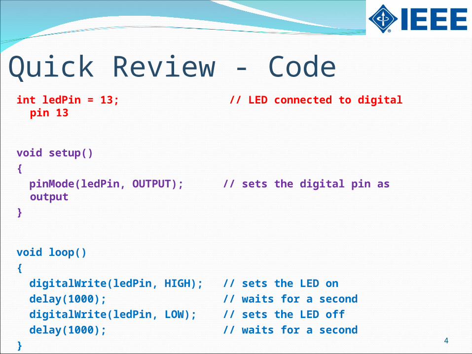
Quick Review - Codeint ledPin = 13; // LED connected to digital pin 13
void setup(){ pinMode(ledPin, OUTPUT); // sets the digital pin as output}
void loop(){ digitalWrite(ledPin, HIGH); // sets the LED on delay(1000); // waits for a second digitalWrite(ledPin, LOW); // sets the LED off delay(1000); // waits for a second}
5
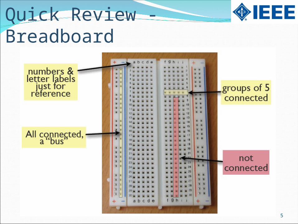
Quick Review - Breadboard

6
Infrared Proximity SensorSend infrared light through IR-LEDs, which is then
reflected by any object in front of the sensor.
7
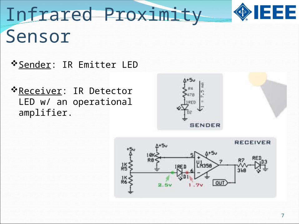
Infrared Proximity SensorSender: IR Emitter LED
Receiver: IR Detector LED w/ an operational amplifier.
8
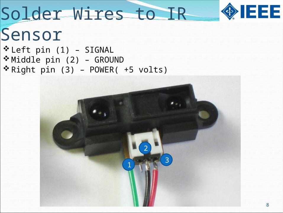
Solder Wires to IR SensorLeft pin (1) – SIGNALMiddle pin (2) – GROUNDRight pin (3) – POWER( +5 volts)
1
2
3
9
How to Solder Wires to IR Sensor
1. Warm up the iron
2. Prepare a moisten sponge
3. Apply heat to the lead.
4. Apply solder to the lead
5. Allow solder to cool down
6. Inspect the connection
10
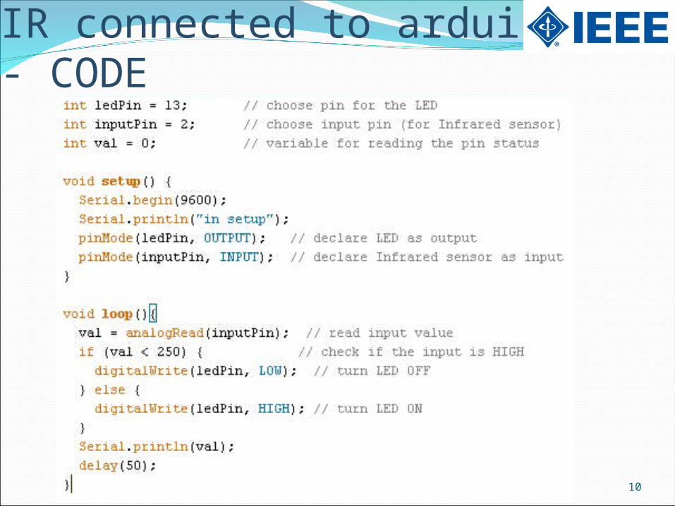
IR connected to arduino - CODE
11
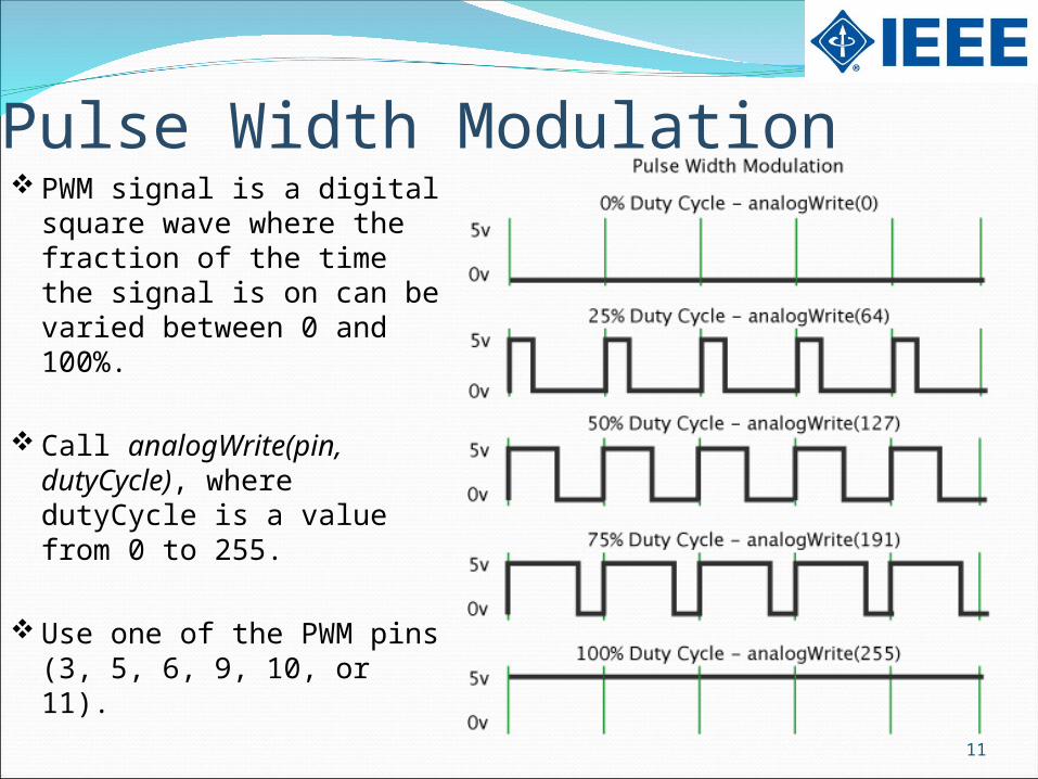
Pulse Width Modulation PWM signal is a digital square
wave where the fraction of the time the signal is on can be varied between 0 and 100%.
Call analogWrite(pin, dutyCycle), where dutyCycle is a value from 0 to 255.
Use one of the PWM pins (3, 5, 6, 9, 10, or 11).
12
Applications of Pulse Width ModulationDimming an LED
Generating audio signals.
Generating a modulated signal, for example to drive an infrared LED for a remote control.
Providing variable speed control for motors.
13
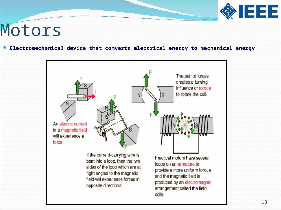
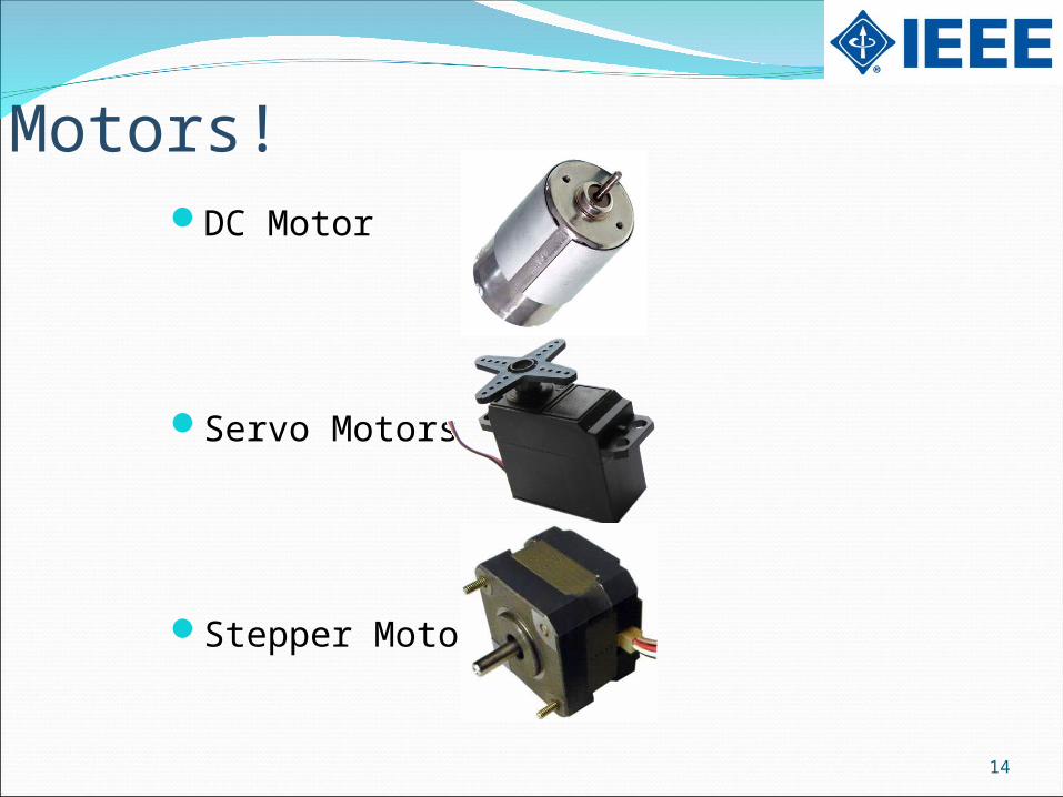
Motors Electromechanical device that converts electrical energy to mechanical energy
14
Motors!DC Motor
Servo Motors
Stepper Motor
15
DC Motor
ProsSimple & cheap (only 2 wires)Fast & can be geared down for higher torqueEasy to reverseSpeed control through PWM
ConsNo built-in feedback
16
Servo Motor (DC motor w/ feedback)
ProsSimple (3 wire) and “Standard”accurate even under loadHigh torque
ConsSlowerMore expensive
17
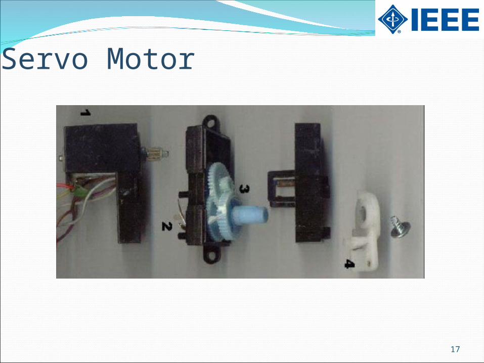
Servo Motor
18
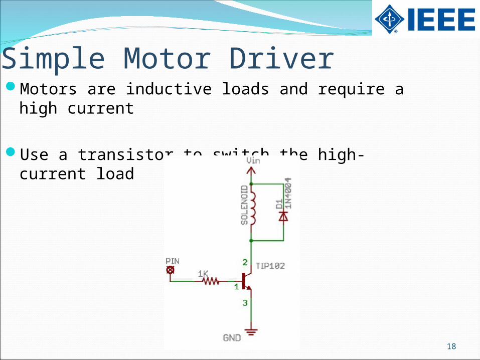
Simple Motor DriverMotors are inductive loads and require a high
current
Use a transistor to switch the high-current load
19
H-Bridge
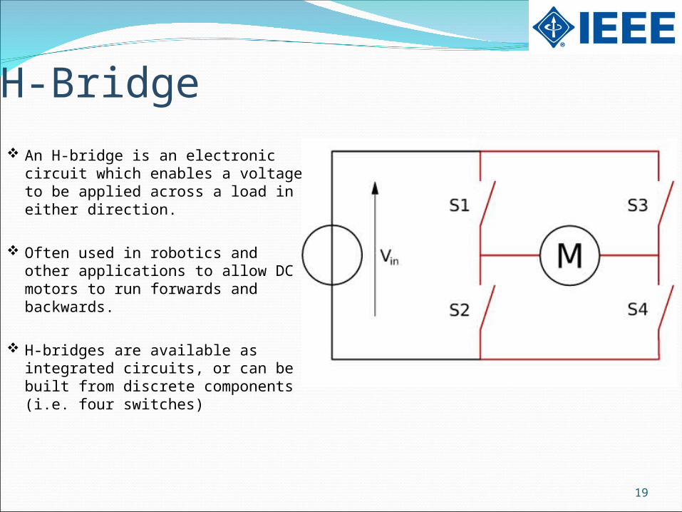
An H-bridge is an electronic circuit which enables a voltage to be applied across a load in either direction.
Often used in robotics and other applications to allow DC motors to run forwards and backwards.
H-bridges are available as integrated circuits, or can be built from discrete components (i.e. four switches)
20
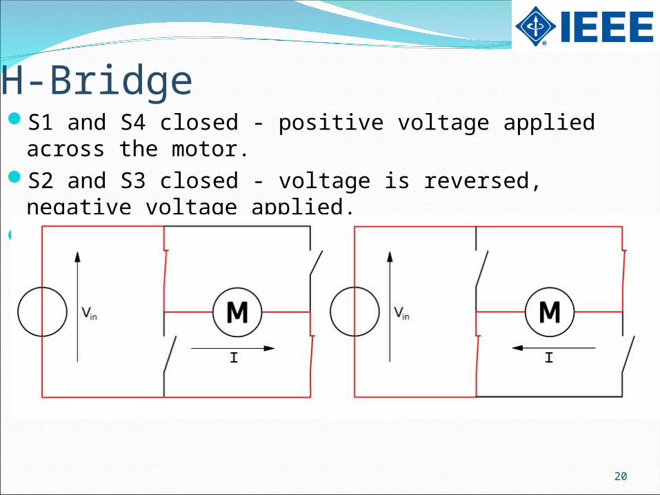
H-BridgeS1 and S4 closed - positive voltage applied across
the motor. S2 and S3 closed - voltage is reversed, negative
voltage applied.S1 and S2 (or S3 and S4) closed – short circuit!
21
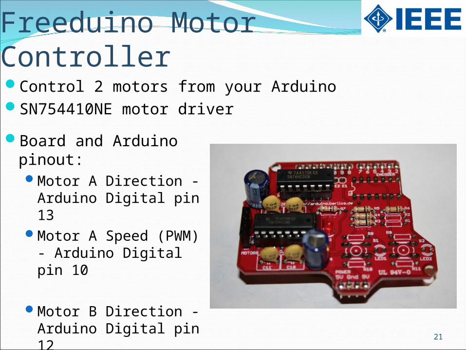
Freeduino Motor ControllerControl 2 motors from your ArduinoSN754410NE motor driver
Board and Arduino pinout:Motor A Direction -
Arduino Digital pin 13Motor A Speed (PWM)
- Arduino Digital pin 10
Motor B Direction - Arduino Digital pin 12
Motor B Speed (PWM) - Arduino Digital pin 9
22
Assembling Freeduino Motor Controller
GO TO: WWW.GOOGLE.COMTYPE: FREEDUINO MOTORCLICK ON THE FIRST LINK
CLICK THE LINK: “THIS GUIDE”
Or Type the following in the address bar:http://mcukits.com/2009/03/12/assembling-the-freeduino-
arduino-motor-shield/
23
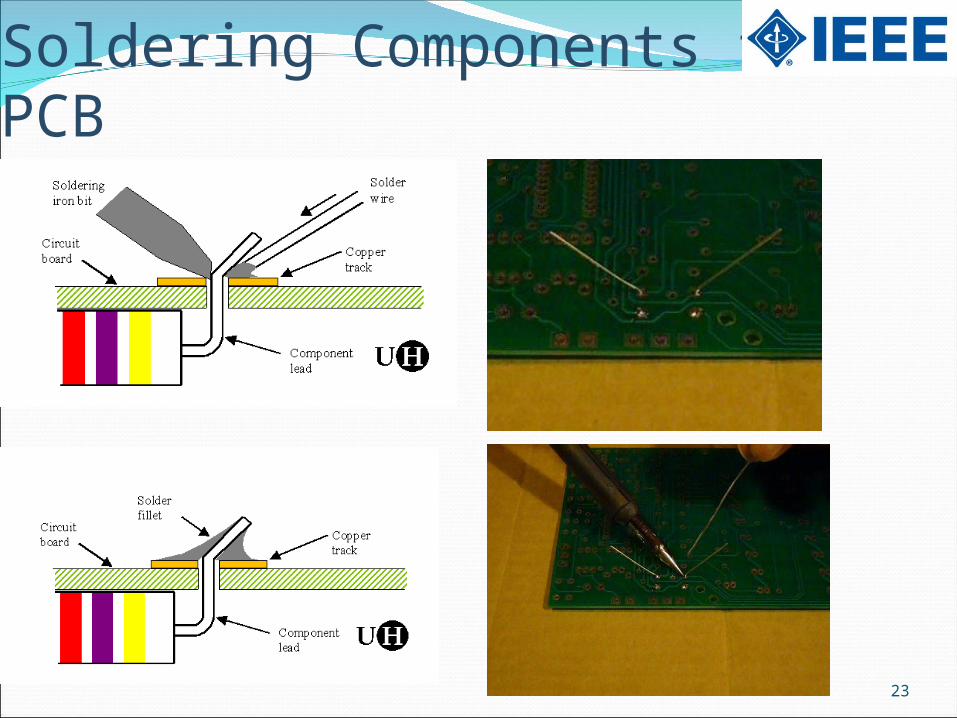
Soldering Components to PCB

24
Robot Design
Discuss Robot Plans with Team Members!

25
Questions or
Comments?