micro controllers project
77
AUTOMATIC SLOT INDICATOR CAR PARKING USING AT89C51 MICROCONTROLLER 1
description
Our demonstration facility presents a miniature model of an automated car parking system that regulates the number of cars that can be parked in a given space at any given time based on the parking space availability.
Transcript of micro controllers project
AUTOMATIC SLOT INDICATOR CAR
PARKING USING AT89C51
MICROCONTROLLER
1
content
CONTENTS Page No.
Abstract 4
1. Introduction 5
2. Flow diagram 8
3. Hardware description
(i). AT89C51 microcontroller
(ii). IR Sensors
(iii). Amplifying circuit
(a). NPN 547 Transistor
(b).Resistor
(c).Voltage supply
(iv). 16X2 LCD
4. Software description 39
5. Schematic connections 47
6. Advantages 49
7. Uses and implementation 50
8. Future scope 51
9. Conclusion 52
10. Reference 53
2
ABSTRACT
Due to the increase in the number of vehicles on the road, traffic
problems are bound to exist. This is due to the fact that the current
transportation infrastructure and car park facility developed are unable to
cope with the influx of vehicles on the road. To alleviate the fore
mentioned problems, the smart card parking system has been developed.
With the implementation of the parking system, patrons can easily locate
and secure a vacant parking space at any car park deemed convenient to
them.
In this car parking system slots are allocated to the cars. Empty and filled
slots can be displayed on the LCD and the various problems related to
parking can be easily solved. There would be no traffic jam and no
wasting of time in searching of different parking areas.
This system is effectively in use in most of the European countries and
many of the American states. This design is mainly comprised of low
manual operation as well as efficient equipment can be installed any of
the commercial, industrial, apartments, institutions/universities, etc.
Hence it is a low cost apparatus as it mainly uses a microcontroller which
is programmable, which is easy to install in any of the above places
mentioned
3
INTRODUCTION
Automobiles are synonyms for mobility and freedom. An amazing
increase in the growth of population in this world leads to the rapid
increase in the number of vehicle being used. With the growing number
of vehicles and the consequent shortage of parking space, there is
haphazard and totally unregulated parking of vehicles all over. In densely
populated areas they are real challenge for city planners, architects and
developers. The need to offer sufficient parking spaces is a task for
specialists. This situation calls for the need for an automated parking
system that not only regulates parking in a given area but also keeps the
manual control to a minimum. Automatic car parking systems is the sole
solution to park as many cars as possible in as little space as possible.
Automatic car parking systems are based on the most modern technology
of storage systems.
Our demonstration facility presents a miniature model of an automated
car parking system that regulates the number of cars that can be parked in
a given space at any given time based on the parking space availability.
It requires no attendants and is more cost-effective than conventional
garages, and allows more cars to be parked in less space. The automation
technology is used to typically double to triple the capacity of
conventional parking garages. The main objective of this system is to
optimize the ground space available, for parking. In places where more
than 100 cars need to be parked, this system proves to be very useful.
Automatic Car Parking System enables the parking of vehicles, floor after
floor, by displaying the available slots thus reducing the ground space
used. Here any number of cars can be parked according to the
requirement, making the system modernized and a space-saving one.
4
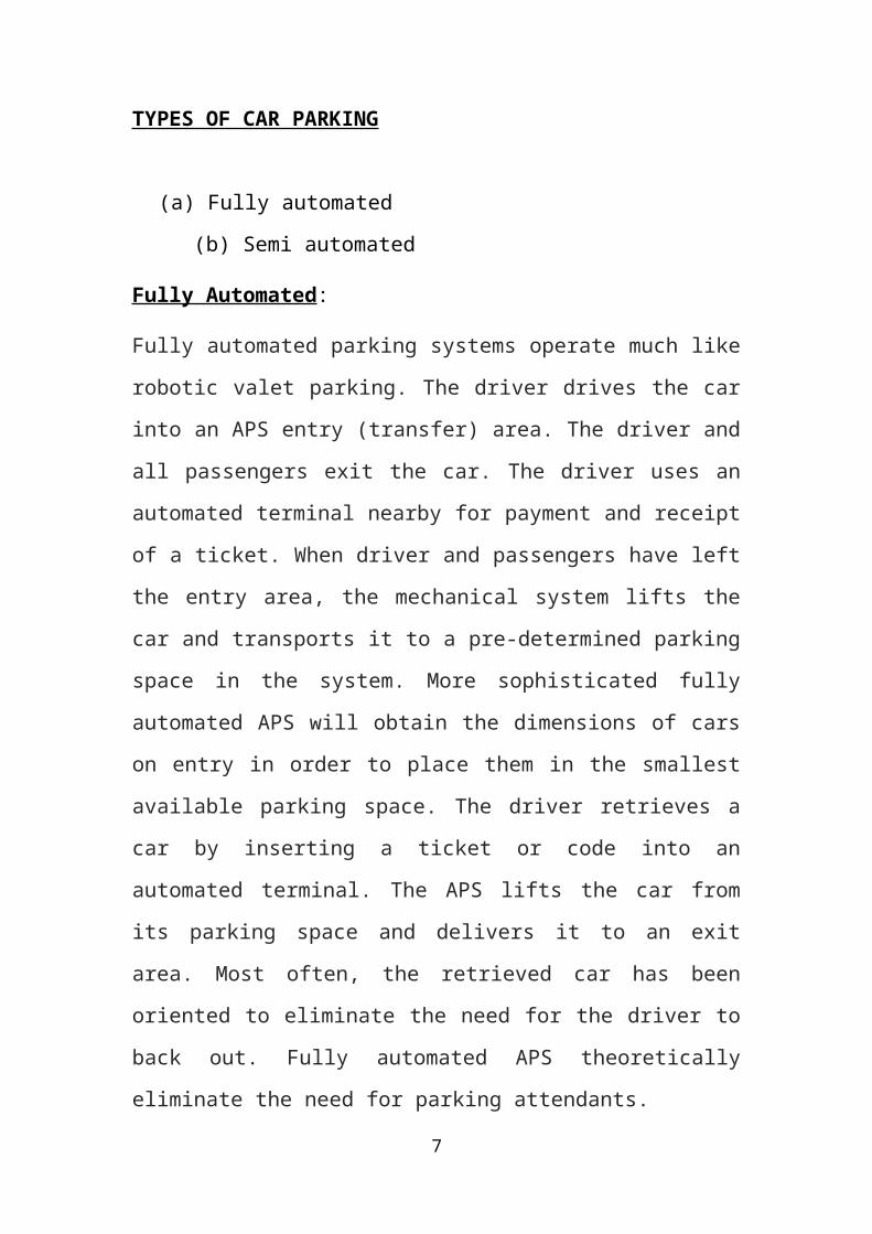
TYPES OF CAR PARKING
(a) Fully automated
(b) Semi automated
Fully Automated:
Fully automated parking systems operate much like robotic valet parking.
The driver drives the car into an APS entry (transfer) area. The driver and
all passengers exit the car. The driver uses an automated terminal nearby
for payment and receipt of a ticket. When driver and passengers have left
the entry area, the mechanical system lifts the car and transports it to a
pre-determined parking space in the system. More sophisticated fully
automated APS will obtain the dimensions of cars on entry in order to
place them in the smallest available parking space. The driver retrieves a
car by inserting a ticket or code into an automated terminal. The APS lifts
the car from its parking space and delivers it to an exit area. Most often,
the retrieved car has been oriented to eliminate the need for the driver to
back out. Fully automated APS theoretically eliminate the need for
parking attendants.
Semi Automated:
Semi-automated APS also use a mechanical system of some type to move
a car to its parking space, however putting the car into and/or the
operation of the system requires some action by an attendant or the
driver.
The choice between fully and semi-automated APS is often a matter of
space and cost, however large capacity (> 100 cars) tend to be fully
automated
5
Characteristics of automatic car parking system suitable for Indian
environment
On the basis of critical study of automatic and semi automatic car parking
systems, it can be concluded that automatic car Parking System Suitable
for Indian Environment should have following Characteristics:
1. The car parking system should be semi automatic to minimize the cost.
2. The car parking system should multistoried to minimize the floor space
required per car.
3. A lift has to be provided to take the car to the upper stories.
4. Two doors have to be provided in the car lift for entry and exit of
vehicle.
5. LED and LCD display screen on each floor will be provided to display
data about available and non available parking slots.
6. An addition lift is provided which connects all the floors for the driver
to return to ground floor after parking the car.
6
2. FLOW DIAGRAM
TTT
7
Transmitter- Receiver Sensor
Amplifier Circuit
Microcontroller Circuit
Display Unit
3. HARDWARE DESCRIPTION
In this project we use many hardware materials. Every hardware
component have its own functions and own specifications. Every
component performs different functions. These components can be
implanted in many instruments by different means. Now, here we will
discuss the different hardware components used in our project.
(i). AT89C51 Microcontroller
(ii). IR Sensors
(iii). Amplifying circuit
(a). NPN transistor
(b). Resistors
(c). Voltage supply
iv. 16X2 LCD
Now we will describe every component used in project in detail.
(i) MICROCONTROLLER - AT89C51
Microcontroller is a single chip computer or A CPU with all peripherals
like RAM,ROM,I/O PORTS,ADC,TIMERS etc. on same chip. For ex:
intel's 8051, Motorola's 6811 etc.
The block diagram of the 8051 shows all of the features unique to
microcontrollers:
1. Internal ROM and RAM
2. I/O ports with programmable pins
3. Timers and counters
4. Serial data communication
8
The block diagram also shows the usual CPU components program
counter, ALU, working registers, and the clock circuits.
The 8051 architecture consists of these specific features:
1. 8 bit CPU with registers A and B
2. 16 bit PC &data pointer (DPTR)
3. 8 bit program status word (PSW)
4. 8 bit stack pointer (SP)
5. Internal ROM or EPROM (8751) of 0(8031)to 4k(8051)6. Internal RAM of 128 bytes.
7. 4 register banks, each containing 8 registers
8. 80 bits of general purpose data memory
9. 32 input/output pins arranged as four 8 bit ports: P0-P3
10. Two 16 bit timer/counters: T0-T1
11. Two external and three internal interrupt sources
12. Oscillator and clock circuits
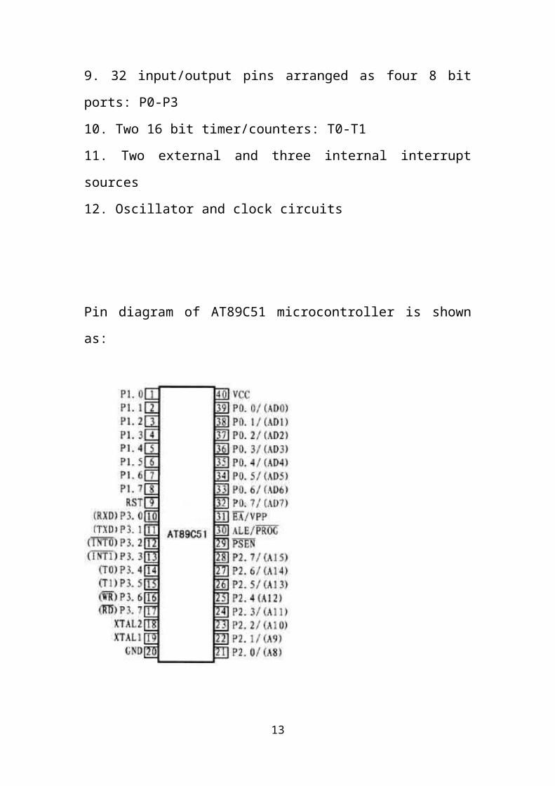
Pin diagram of AT89C51 microcontroller is shown as:
9
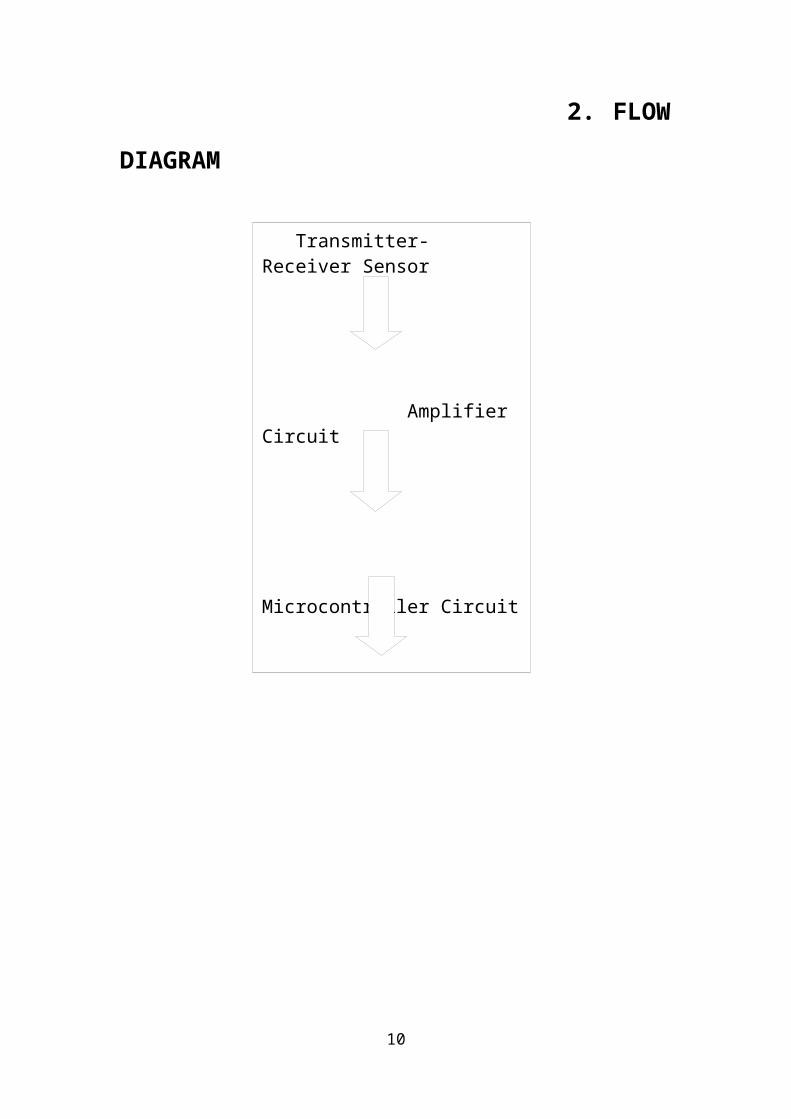
Figure1: Pin diagram of AT89C51
Now we will briefly describe every part of the microcontroller:
AT89C51 is an 8-bit microcontroller and belongs to Atmel's 8051 family.
ATMEL 89C51 has 4KB of Flash programmable and erasable read only
memory (PEROM) and 128 bytes of RAM. It can be erased and program
to a maximum of 1000 times.
In 40 pin AT89C51, there are four ports designated as P1, P2, P3 and P0.
All these ports are 8-bit bi-directional ports, i.e., they can be used as both
input and output ports. Except P0 which needs external pull-ups, rest of
the ports have internal pull-ups. When 1s are written to these port pins,
they are pulled high by the internal pull-ups and can be used as inputs.
These ports are also bit addressable and so their bits can also be accessed
individually port P0 and P2 are also used to provide low byte and high
10
byte addresses, respectively, when connected to an external memory. Port
3 has multiplexed pins for special functions like serial communication
hardware interrupts, timer inputs and read/write operation from external
memory. AT89C51 has an inbuilt UART for serial communication. It can
be programmed to operate at different baud rates. Including two timers&
hardware interrupts, it has a total of six interrupts. Pins can be described
as follows:
VCC
Positive (+ve) Dc Supply voltage which is normally between 3V to 5V
Dc.
GND
0 Volt ground. This pin is connected to -ve dc supply voltage.
PORTS
Ports are generally used by computers to communicate to the outside
world. Microcontrollers use port to read input from another device or to
send output to another device. At89C51 has four ports for
communication.
Port 0, Port 1, Port 2, Port 3
These ports are 8-bit bi-directional I/O ports. They can be used for both
input and output ports. As an output port, each pin can sink eight TTL
inputs. Port can be used as an input when they are made to read data from
another device (which can be a component or a sensor) or as an output
when they are used to send a signal to another device. They basically
understand two logic states that are 1s and 0s.
RST
11
Reset input. This pin is used to reset the microcontroller. If a high
remains on this pin for two machine cycles while the oscillator is running,
the microcontroller is reset.
ALE/PROG
Address Latch Enable output pulse for latching the low byte of the
address during accesses to external memory. This pin is also the program
pulse input (PROG) during flash programming. This pin is used to
control microcontroller. Setting the ALE-disable bit has no effect if the
microcontroller is in external execution mode.
PSEN
Program Store Enable is the read strobe to external program memory.
When the AT89C51 is executing code from external program memory,
PSEN is activated twice each machine cycle, except that two PSEN
activations are skipped during each access to external data memory.
EA/VPP
External Access Enable (EA) must be strapped to GND in order to enable
the device to fetch code from external program memory locations starting
at 0000H up to FFFFH. Note, however, that if lock bit 1 is programmed,
EA will be internally latched on reset. EA should be strapped to VCC for
internal program executions. This pin also receives the 12-volt
programming enable voltage (VPP) during Flash programming, for parts
that require 12 volt VPP.
XTAL1
Input to the inverting oscillator amplifier and input to the internal clock
operating circuit. This pin is connected to the external crystal oscillator
together with XTAL2.
XTAL2
Output from the inverting oscillator amplifier
12
Registers
In the CPU, registers are used to store information temporarily. That
information could be a byte of data to be processed, or an address
pointing to the data to be fetched. The vast majority of 89C51 register an
address pointing to the data to be fetched. The vast majority of 89C51
registers are 8-bit registers. In the 8051 there is only one data type: 8 bits.
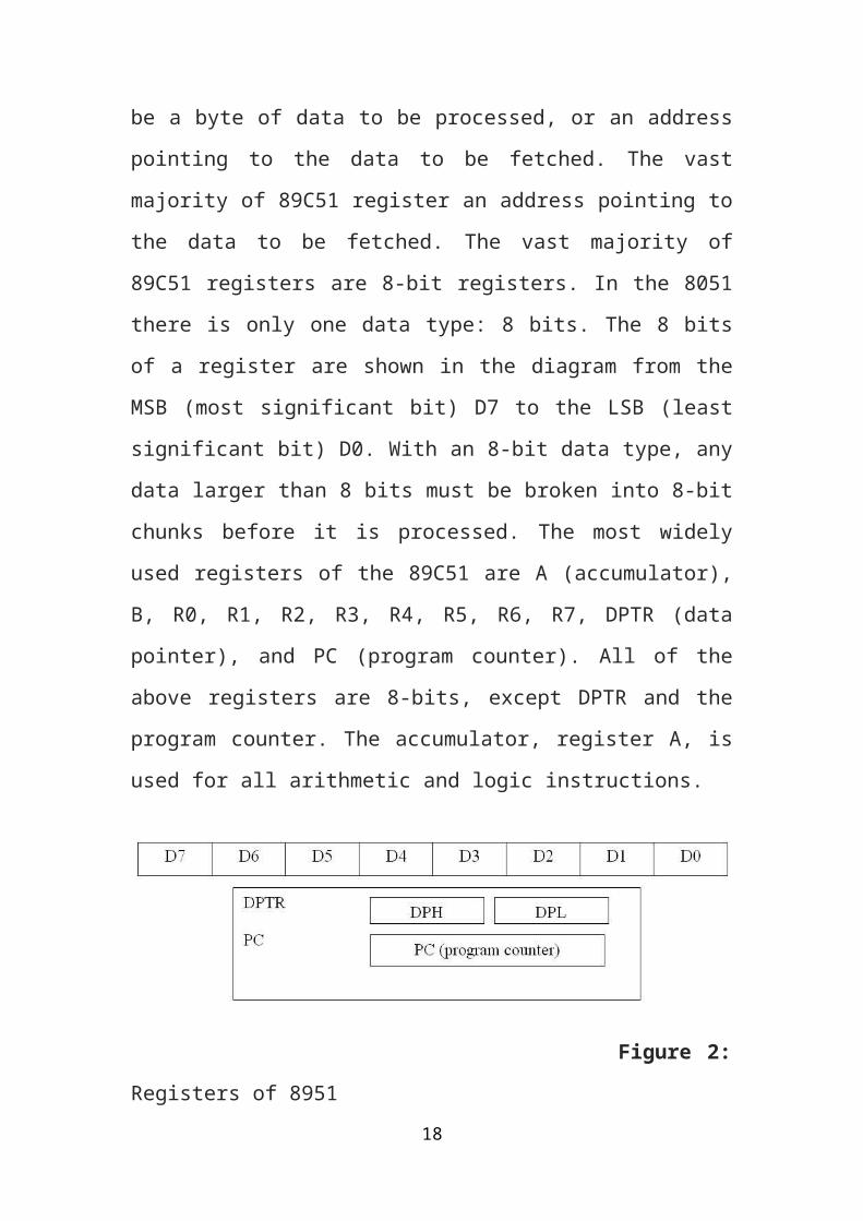
The 8 bits of a register are shown in the diagram from the MSB (most
significant bit) D7 to the LSB (least significant bit) D0. With an 8-bit data
type, any data larger than 8 bits must be broken into 8-bit chunks before it
is processed. The most widely used registers of the 89C51 are A
(accumulator), B, R0, R1, R2, R3, R4, R5, R6, R7, DPTR (data pointer),
and PC (program counter). All of the above registers are 8-bits, except
DPTR and the program counter. The accumulator, register A, is used for
all arithmetic and logic instructions.
Figure 2: Registers of 8951
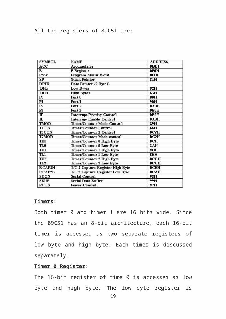
All the registers of 89C51 are:
13
Timers:
Both timer 0 and timer 1 are 16 bits wide. Since the 89C51 has an 8-bit
architecture, each 16-bit timer is accessed as two separate registers of low
byte and high byte. Each timer is discussed separately.
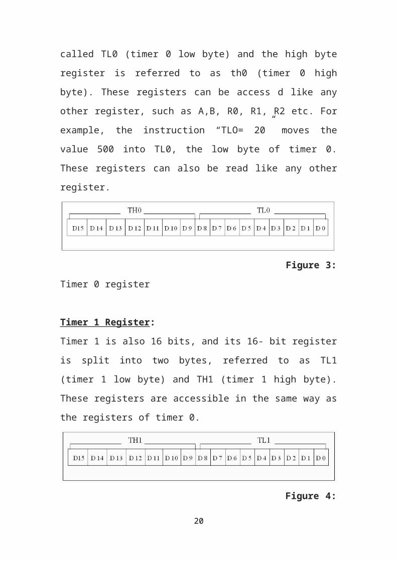
Timer 0 Register:
The 16-bit register of time 0 is accesses as low byte and high byte. The
low byte register is called TL0 (timer 0 low byte) and the high byte
register is referred to as th0 (timer 0 high byte). These registers can be
access d like any other register, such as A,B, R0, R1, R2 etc. For
example, the instruction “TLO= 20” moves the value 500 into TL0, the
low byte of timer 0. These registers can also be read like any other
register.
14
Figure 3: Timer 0 register
Timer 1 Register:
Timer 1 is also 16 bits, and its 16- bit register is split into two bytes,
referred to as TL1 (timer 1 low byte) and TH1 (timer 1 high byte). These
registers are accessible in the same way as the registers of timer 0.
Figure 4: Timer 1 register
TMOD (Timer Mode) Register:
Both timers 0 and 1 uses the same register, called TMOD, to set the
various timer operation modes. TMOD is an 8-bit register in which the
lower 4 bits are set aside for timer 0 and the upper 4 bits are set aside for
timer 1. In each case, the lower 2 bits are used to set the timer mode and
the upper 2 bits to specify the operation.
Mode 2 Programming:
The following are the characteristics and operations of mode 2.
1-It is an 8-bit timer; therefore, it allows only values of 00 to FFH to be
loaded into the timer’s register TH.
2-After TH is loaded with the 8-bit value, the 8051 gives a copy of it to
TL. Then the timer must be started. This is done by the instruction
“SETB TR0” for timer 0 and “SETB TR1” for timer 1. This is just like
15
mode 1.
3-After the timer started, it starts to count up by incrementing the TL
register. It counts up until it reaches its limit of FFH. When it rolls over
from FFH to 00, it sets high the TF (timer flag). If we are using timer 0,
TF0 goes high; if we are using timer 1, TF1 is raised.
4-When the TL registers rolls from FFH to 0 and TF is set to 1, TL is
reloaded automatically with the original value kept by the TH register. To
repeat the process, we must simply clear TF and let it go without any
need by the programmer to reload the original value. This makes mode 2
and auto-reload, in contrast with mode 1 in which the programmer has to
reload TH and TL.
It must be emphasized that mode 2 is an 8-bit timer. However, it has an
auto-reloading capability in auto reload. TH is loaded with the initial
count and a copy of it is given to TL. This reloading leaves TH
unchanged, still holding a copy of original value. This mode has many
applications, including setting the baud rate in serial communication.
SBUF (Serial Buffer) Register:
SBUF is an 8-bit register used solely for serial communication in the
89C51. For a byte of data to be transferred via the TxD line, it must be
placed in the SBUF register. Similarly, SBUF holds the byte of data when
it is received by the 89C51 RxD line. SBUF can be accessed like any
other register in the 89C51.The moment a byte is written into SBUF, it is
framed with the start and stop bits and transferred serially via the TxD
pin. Similarly, when the bits are received serially via RxD, the 89C51
deframes it by eliminating the stop and start bits, making a byte out of the
data received, and then placing it in the SBUF. Some baud rates are
shown below:
Baud Rate= 9600 TH1(Decimal)=-3 TH1(HEX)=FD
Baud Rate= 4800 TH1(Decimal)=-6 TH1(HEX)=FA
16
Baud Rate= 2400 TH1(Decimal)=-12 TH1(HEX)=F4
Baud Rate= 1200 TH1(Decimal)=-24 TH1(HEX)=E8
SCON (Serial Control) Register:
The SCON register is an 8-bit register used to program the start bit, stop
bit, and data bits of data framing, among other things. Following SCON
bits are explained; SMO SCON.7 Serial port mode specifier
SM1/ SCON.6= Serial port mode specifier
SM2/ SCON.5= Used for multiprocessor communication (Make it 0)
REN/ SCON.4= Set / cleared by software to enable / disable reception.
TB8/ SCON.3= Not widely used.
RB8/ SCON.2= Not widely used.
T1/ SCON.1= Transmit interrupt flag. Set by hardware at the beginning
of the stop bit in mode1must by cleared by software.
R1/ SCON.0= Receive interrupt flag. Set by hardware halfway through
the stop bit time in mode1must be cleared by software.
Bit-Addressable RAM:
Of the 128-byts internal RAM of the 8051, only 16 bytes of it are bit
addressable. The rest must be accessed in byte format. The bit –
addressable RAM locations are 20H to 2FH. These 16 bytes provide 128
bits of RAM bit – address ability since 16 x 8 = 128. They are addressed
as 0 to 127 (in decimal) or 00 to 7FH. Therefore, the bit addresses 0 to 7
are for the first byte of internal RAM location 20H, and 8 to 0FH are the
bit addresses of the second byte, RAM location 21H, and so on. The last
byte of 2FH has bit address byte of 2FH has bit addresses of 78H to 7FH.
Note that internal RAM locations 20-2FH are both byte-addressable and
bit addressable. Notice from figure that bit addresses 00 – 7FH belong to
RAM byte addresses 20 – 2FH, and bit addresses 80 – F7H belong to
SFR P0, P1 etc.
17
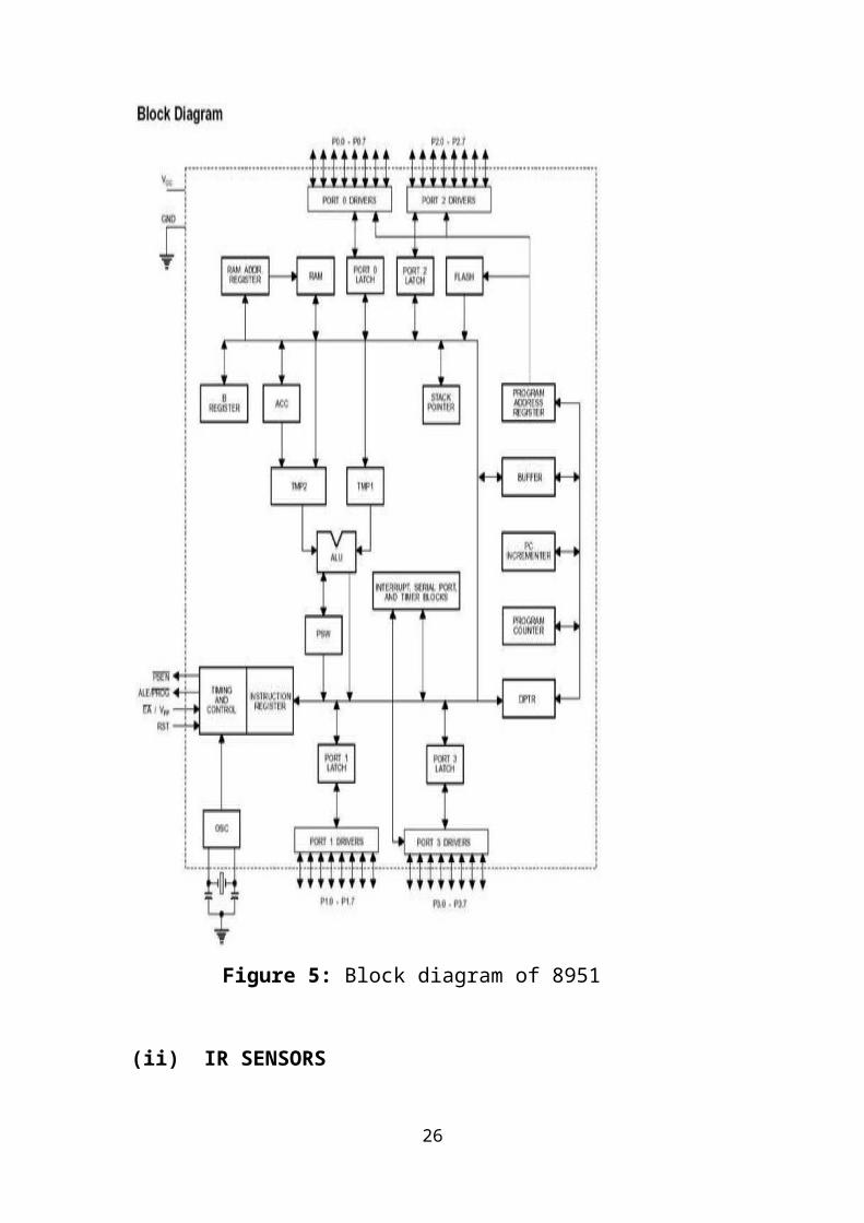
Block diagram of 8951 can viewed as:
Figure 5: Block diagram of 8951
18
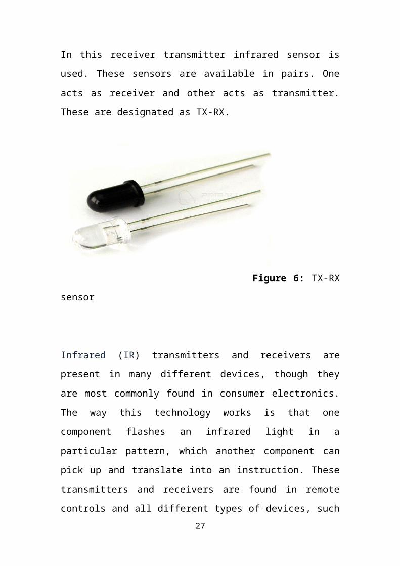
(ii) IR SENSORS
In this receiver transmitter infrared sensor is used. These sensors are
available in pairs. One acts as receiver and other acts as transmitter.
These are designated as TX-RX.
Figure 6: TX-RX sensor
Infrared (IR) transmitters and receivers are present in many different
devices, though they are most commonly found in consumer electronics.
The way this technology works is that one component flashes an infrared
light in a particular pattern, which another component can pick up and
translate into an instruction. These transmitters and receivers are found in
remote controls and all different types of devices, such as televisions and
DVD players. Peripheral devices that include this technology can also
allow a computer to control various other consumer electronics. Since
infrared remotes are limited to line of sight operation, some products can
be used to extend the signals over a hardwired line or radio frequency
(RF) transmissions.
19
Most common consumer electronic remote controls use infrared light.
They typically generate infrared using light emitting diodes (LEDs), and
the main component of a receiver unit is usually a photodiode. A remote
control flashes a pattern of invisible light, which is picked up and then
turned into an instruction by the receiver module. The parts necessary to
construct transmitter and receiver are typically inexpensive, but these
systems are limited to line of sight operation.
Infrared Sensors are of two types: Thermal & Quantum:
Thermal type sensors have no wavelength dependence. They use the
infrared energy as heat and their photosensitivity is independent of
wavelength. Thermal detectors don’t require cooling but have
disadvantages that response time is slow & detection time is low.
Common types of thermal type IR detectors are:
Thermocouple-Thermopile:
A detector that converts temperature into an electrical signal is commonly
known as a thermocouple. The junction of dissimilar metals generates a
voltage potential, which is directly proportional to the temperature. This
junction can be made into multiple junctions to improve sensitivity. Such
a configuration is called a thermopile. The active or ‘Hot’ junctions are
blackened to efficiently absorb radiation. The reference or ‘Cold’
junctions are maintained at the ambient temperature of the detector. The
absorption of radiation by the blackened area causes a rise in temperature
in the ‘hot’ junctions as compared to the ‘cold’ junctions of the
thermopile. This difference in temperature across the thermocouple
junction causes the detector to generate a positive voltage. If the active or
‘hot’ junction were to cool to a temperature less than the reference or
‘cold’ junction the voltage output would be negative.These detectors has
20
a relatively slow response time, but offers the advantages of DC stability,
requiring no bias, and responding to all wavelengths.
Bolometer:
A bolometer is a simple thermal or total power detector. A bolometer
changes resistance when incident infrared radiation interacts with the
detector. This thermally sensitive semiconductor is made of a sintered
metal oxide material. It has a high temperature coefficient of resistance
It essentially consists of two main elements: a sensitive thermometer and
an absorptive element and a heat sink. Absorber is connected by a weak
thermal link to a heat sink (at temperature T0). Incoming energy increases
the temperature of the absorptive element above that of a heat sink and
rise in temperature is measured by a thermometer.
Delta T = T - T0 = E/C
Figure 7: Bolometer
Bolometer use metals or semiconductor/superconductors as absorptive
elements.
Pyroelectric detector:
Pyroelectric detectors use PZT having pyroelectric effect, a high resistor
and a low noise FET, hermetically sealed in a package. Pyroelectric
materials are crystals, such as lithium tantalate, which exhibit
spontaneous polarization, or a concentrated electric charge that is
temperature dependent. PZT is spontaneously polarized in dark state. As
21
infrared radiation strikes the detector surface, the change in temperature
causes a current to flow. This results in change of polarization state which
is reflected in terms of voltage change at the output.
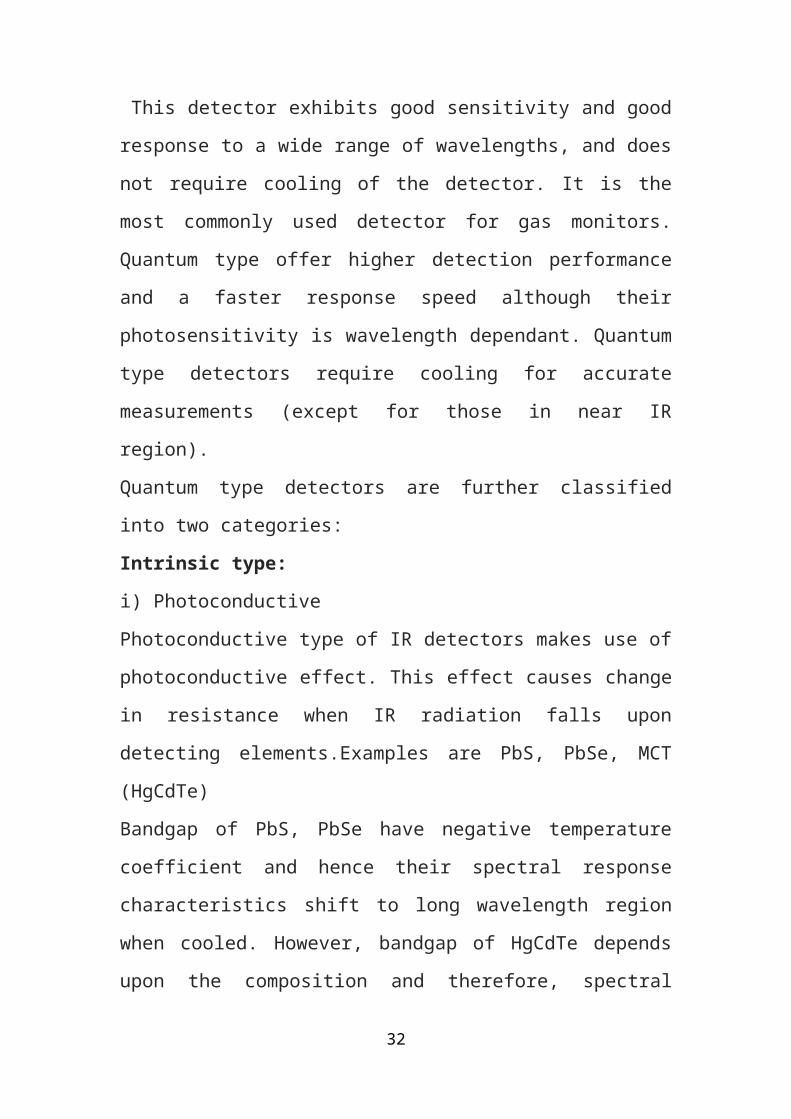
This detector exhibits good sensitivity and good response to a wide range
of wavelengths, and does not require cooling of the detector. It is the
most commonly used detector for gas monitors. Quantum type offer
higher detection performance and a faster response speed although their
photosensitivity is wavelength dependant. Quantum type detectors require
cooling for accurate measurements (except for those in near IR region).
Quantum type detectors are further classified into two categories:
Intrinsic type:
i) Photoconductive
Photoconductive type of IR detectors makes use of photoconductive
effect. This effect causes change in resistance when IR radiation falls
upon detecting elements.Examples are PbS, PbSe, MCT (HgCdTe)
Bandgap of PbS, PbSe have negative temperature coefficient and hence
their spectral response characteristics shift to long wavelength region
when cooled. However, bandgap of HgCdTe depends upon the
composition and therefore, spectral response characteristics can be
tailored to suit the requirements.
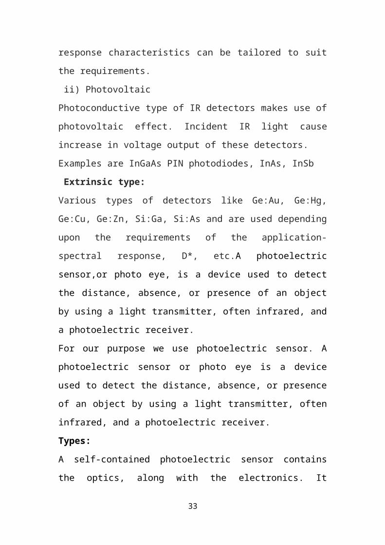
ii) Photovoltaic
Photoconductive type of IR detectors makes use of photovoltaic effect.
Incident IR light cause increase in voltage output of these detectors.
Examples are InGaAs PIN photodiodes, InAs, InSb
Extrinsic type:
Various types of detectors like Ge:Au, Ge:Hg, Ge:Cu, Ge:Zn, Si:Ga,
Si:As and are used depending upon the requirements of the application-
spectral response, D*, etc.A photoelectric sensor,or photo eye, is a device
used to detect the distance, absence, or presence of an object by using a
22

light transmitter, often infrared, and a photoelectric receiver.
For our purpose we use photoelectric sensor. A photoelectric sensor or
photo eye is a device used to detect the distance, absence, or presence of
an object by using a light transmitter, often infrared, and a photoelectric
receiver.
Types:
A self-contained photoelectric sensor contains the optics, along with the
electronics. It requires only a power source. The sensor performs its own
modulation, demodulation, amplification, and output switching. Some
self-contained sensors provide such options as built-in control timers or
counters. Because of technological progress, self-contained photoelectric
sensors have become increasingly smaller.
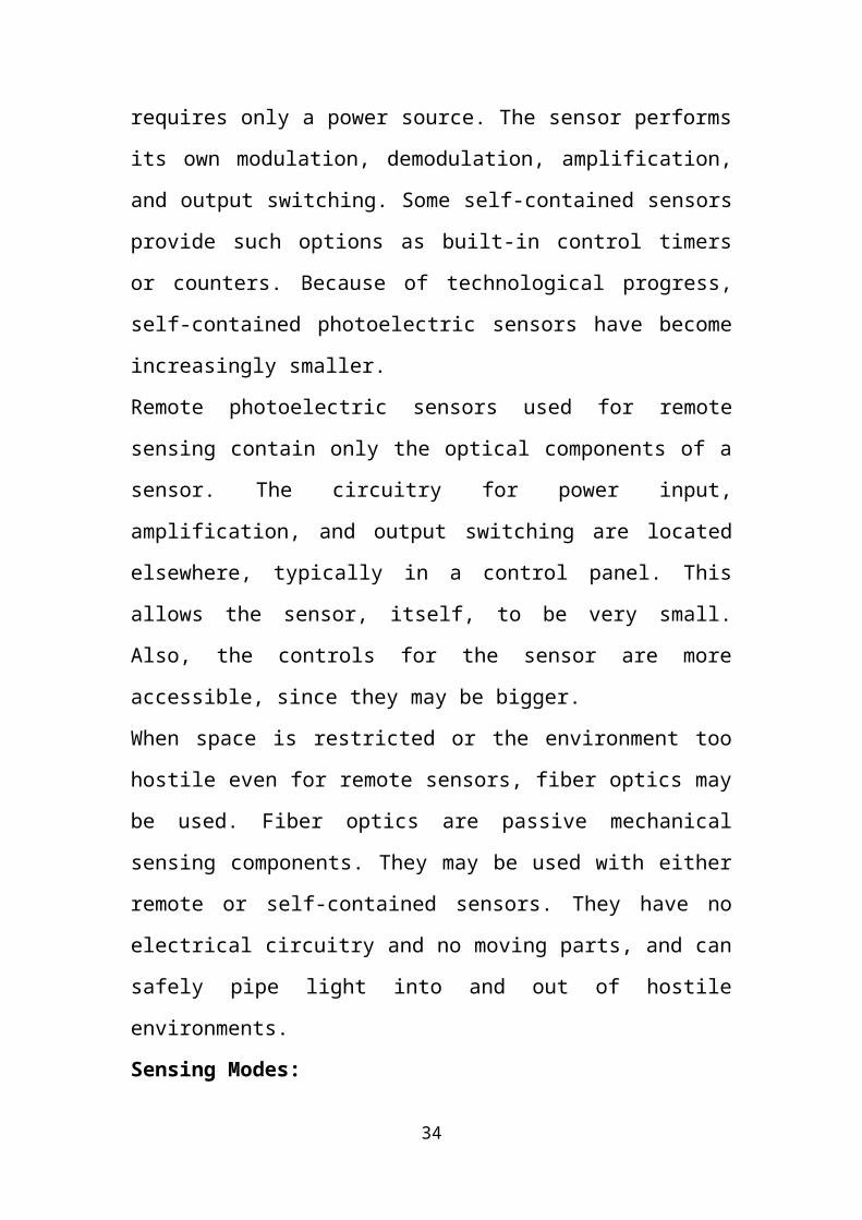
Remote photoelectric sensors used for remote sensing contain only the
optical components of a sensor. The circuitry for power input,
amplification, and output switching are located elsewhere, typically in a
control panel. This allows the sensor, itself, to be very small. Also, the
controls for the sensor are more accessible, since they may be bigger.
When space is restricted or the environment too hostile even for remote
sensors, fiber optics may be used. Fiber optics are passive mechanical
sensing components. They may be used with either remote or self-
contained sensors. They have no electrical circuitry and no moving parts,
and can safely pipe light into and out of hostile environments.
Sensing Modes:
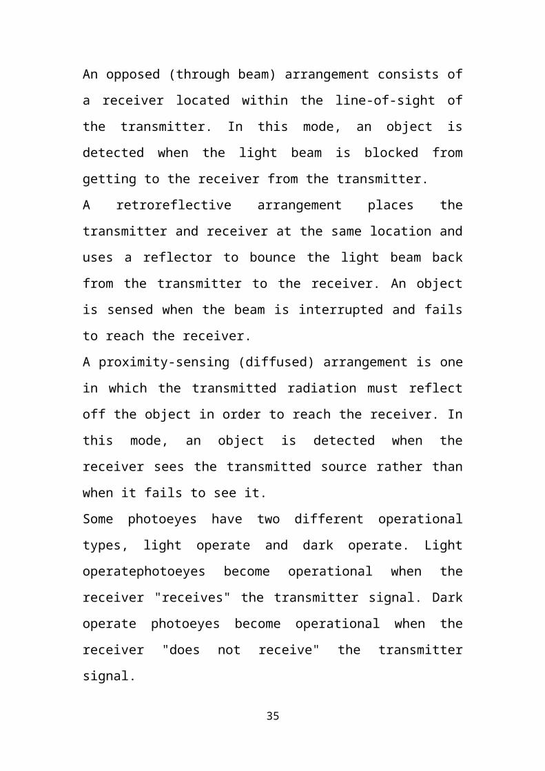
An opposed (through beam) arrangement consists of a receiver located
within the line-of-sight of the transmitter. In this mode, an object is
detected when the light beam is blocked from getting to the receiver from
the transmitter.
A retroreflective arrangement places the transmitter and receiver at the
same location and uses a reflector to bounce the light beam back from the
23
transmitter to the receiver. An object is sensed when the beam is
interrupted and fails to reach the receiver.
A proximity-sensing (diffused) arrangement is one in which the
transmitted radiation must reflect off the object in order to reach the
receiver. In this mode, an object is detected when the receiver sees the
transmitted source rather than when it fails to see it.
Some photoeyes have two different operational types, light operate and
dark operate. Light operatephotoeyes become operational when the
receiver "receives" the transmitter signal. Dark operate photoeyes become
operational when the receiver "does not receive" the transmitter signal.
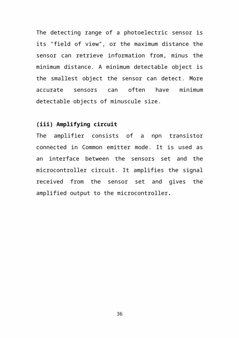
The detecting range of a photoelectric sensor is its "field of view", or the
maximum distance the sensor can retrieve information from, minus the
minimum distance. A minimum detectable object is the smallest object
the sensor can detect. More accurate sensors can often have minimum
detectable objects of minuscule size.
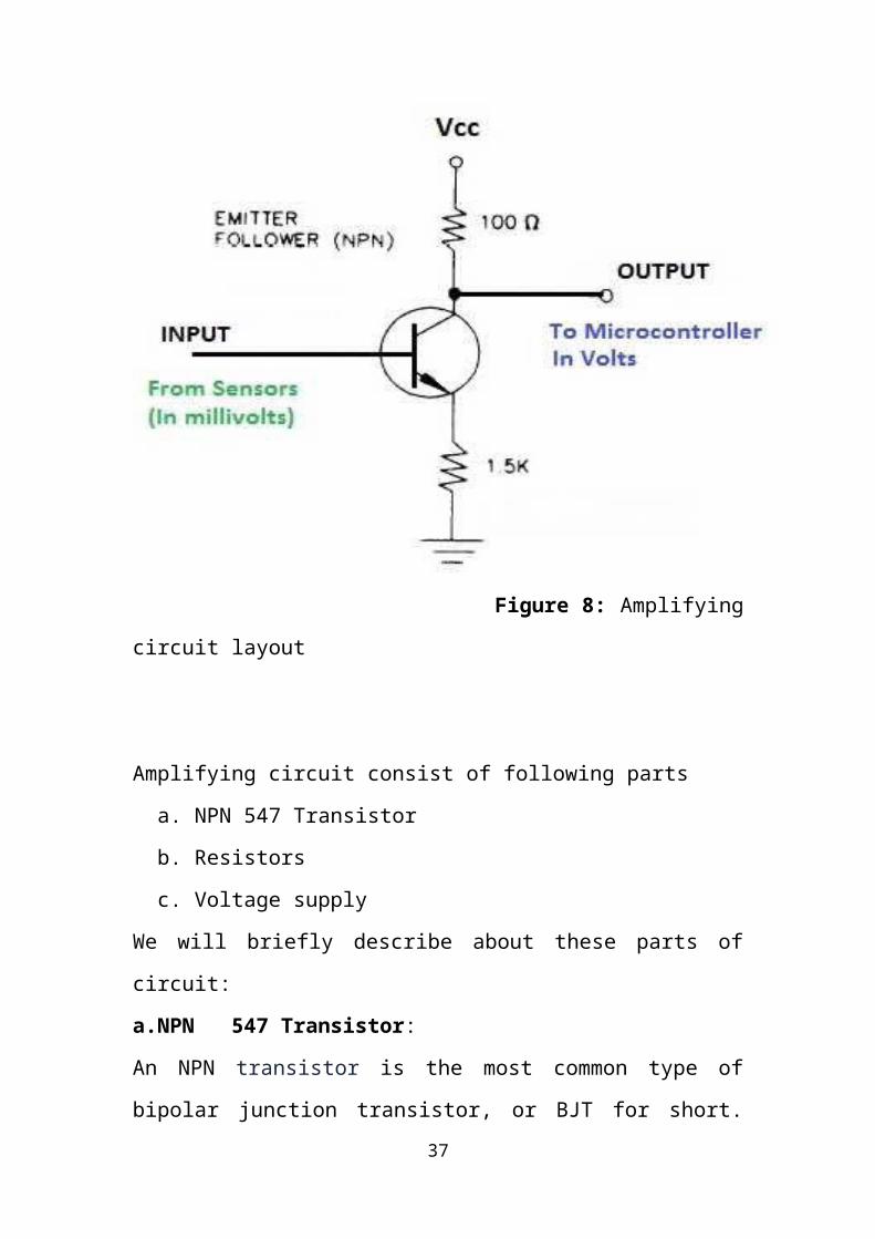
(iii) Amplifying circuit
The amplifier consists of a npn transistor connected in Common emitter
mode. It is used as an interface between the sensors set and the
microcontroller circuit. It amplifies the signal received from the sensor
set and gives the amplified output to the microcontroller.
24
Figure 8: Amplifying circuit layout
Amplifying circuit consist of following parts
a. NPN 547 Transistor
b. Resistors
c. Voltage supply
We will briefly describe about these parts of circuit:
a.NPN 547 Transistor:
An NPN transistor is the most common type of bipolar junction
transistor, or BJT for short. BJTs are often referred to simply as
transistors, and come in two main types: the NPN and the PNP. The "N"
represents a negatively charged layer of material and the "P" represents a
positively charged layer. NPN transistors have a positive layer located in-
25
between two negative layers. Transistors are typically used in circuits for
amplifying or switching electrical signals that pass through them.
The NPN transistor has a shared base used by both the collector and the
emitter layers. The collector and emitter layers are also asymmetrical,
meaning the amount of impurity in one layer does not match the amount
in the other. Impurities are created when forming the material for the
layers because these impurities create the required positive or negative
charge. This process of creating a certain charge by producing impurities
in the material is known as doping.The NPN transistor is commonly used
because it is so easy to produce. For a transistor to work properly, it needs
to be formed from a semiconductor material. Semiconductors include
materials that fall somewhere near the middle on a scale measuring good
and bad conducting materials. Semiconductors can carry some electric
current, but not as much as extremely conductive materials such as metal.
Silicon is one of the most commonly used semiconductors, and NPN
transistors are the easiest transistors to make out of silicon.One
application for an NPN transistor is on a computer's circuit board.
Computers require all their information be translated into binary code,
and this process is accomplished through a plethora of tiny switches
flipping on and off on the computer’s circuit boards. NPN transistors can
be used for these switches. A strong electric signal turns the switch on
while a lack of a signal turns the switch off. Here we use BC547 NPN
Transistor. BC547 is an NPN bi-polar junction transistor. A transistor,
stands for transfer of resistance, is commonly used to amplify current. A
small current at its base controls a larger current at collector & emitter
terminals.BC547 is mainly used for amplification and switching
purposes. It has a maximum current gain of 800. Its equivalent transistors
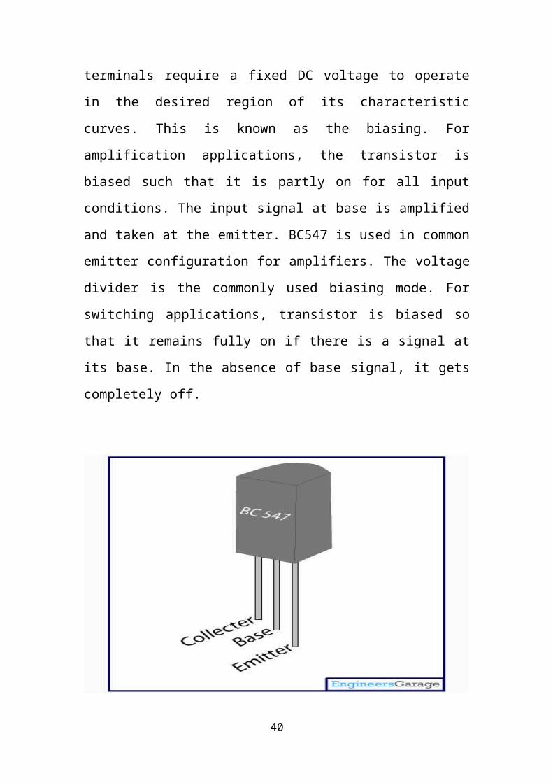
are BC548 and BC549.The transistor terminals require a fixed DC
voltage to operate in the desired region of its characteristic curves. This is
26
known as the biasing. For amplification applications, the transistor is
biased such that it is partly on for all input conditions. The input signal at
base is amplified and taken at the emitter. BC547 is used in common
emitter configuration for amplifiers. The voltage divider is the commonly
used biasing mode. For switching applications, transistor is biased so that
it remains fully on if there is a signal at its base. In the absence of base
signal, it gets completely off.
Figure 9: Pin diagram of BC547 NPN Transistor
b. Resistors:
A resistor is a passive two terminal electric component that implementsas
electrical resistance a circuit element. Resistors act to reduce current
flow, and, at the same time, act to lower voltage levels within circuits.
Resistors may have fixed resistances or variable resistances, such as those
found in thermistor, varistors, trimmers, photoresistors etc.
The current through a resistor is in direct proportion to the voltage across
27
the resistor's terminals. This relationship is represented by Ohm’s Law:
Where I is the current through the conductor in units of amperes, V is the
potential difference measured across the conductor in units of volts, and R
is the resistance of the conductor in units of ohms(symbol: Ω).
The ratio of the voltage applied across a resistor's terminals to the
intensity of current in the circuit is called its resistance, and this can be
assumed to be a constant (independent of the voltage) for ordinary
resistors working within their ratings.
Resistors are common elements of electrical networks and electronic
circuits and are ubiquitous in electronic equipment. Practical resistors can
be composed of various compounds and films, as well as resistance wires
(wire made of a high-resistivity alloy, such as nickel-chrome). Resistors
are also implemented within integrated circuits, particularly analog
devices, and can also be integrated into hybrid and printed circuits. The
electrical functionality of a resistor is specified by its resistance: common
commercial resistors are manufactured over a range of more than nine
orders of magnitude. When specifying that resistance in an electronic
design, the required precision of the resistance may require attention to
the manufacturing tolerance of the chosen resistor, according to its
specific application. The temperature coefficient of the resistance may
also be of concern in some precision applications. Practical resistors are
also specified as having a maximum power rating which must exceed the
anticipated power dissipation of that resistor in a particular circuit: this is
mainly of concern in power electronics applications. Resistors with
higher power ratings are physically larger and may require heat sinks. In
a high-voltage circuit, attention must sometimes be paid to the rated
28
maximum working voltage of the resistor. While there is no minimum
working voltage for a given resistor, failure to account for a resistor's
maximum rating may cause the resistor to incinerate when current is run
through it.
Practical resistors have a series inductance and a small parallel
capacitance; these specifications can be important in high-frequency
applications. In a low noise amplifier or pre-amp, the noise characteristics
of a resistor may be an issue. The unwanted inductance, excess noise, and
temperature coefficient are mainly dependent on the technology used in
manufacturing the resistor. They are not normally specified individually
for a particular family of resistors manufactured using a particular
technology[1].A family of discrete resistors is also characterized
according to its form factor, that is, the size of the device and the position
of its leads (or terminals) which is relevant in the practical manufacturing
of circuits using them.
Units used for resistance: The ohm(symbol:Ω) is the SI unit of electrical
resistance, named after Georg Simon Ohm. An ohm is equivalent to a volt
per ampere. Since resistors are specified and manufactured over a very
large range of values, the derived units of milliohm (1 mΩ = 10−3 Ω),
kilohm (1 kΩ = 103 Ω), and megohm (1 MΩ = 106 Ω) are also in common
usage.The reciprocal of resistance R is called conductance G = 1/R and is
measured in Siemens (SI unit), sometimes referred to as a mho. Hence,
siemens is the reciprocal of an ohm: . Although the concept of
conductance is often used in circuit analysis, practical resistors are always
specified in terms of their resistance (ohms) rather than conductance.
29
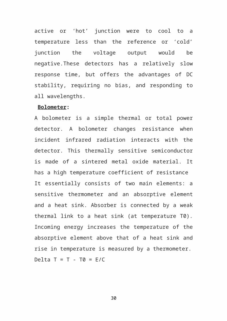
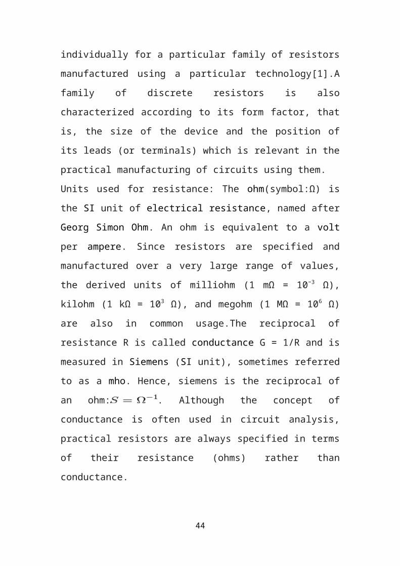
Figure 10: Resistors
For amplifying circuit resistors of 10 ohm and 1.5 kilo ohms are used.
c. Voltage supply:
A voltage source is a two terminal device which can maintain a fixed
voltage. An ideal voltage source can maintain the fixed voltage
independent of the load resistance or the output current. However, a real-
world voltage source cannot supply unlimited current. A voltage source is
the dual of a current source. Real-world sources of electrical energy, such
as batteries, generators, and power systems, can be modeled for analysis
purposes as a combination of an ideal voltage source and additional
combinations of impedence element.
Voltage supply can be applied to the circuit by using batteries or adapters.
A 5V supply is given to the circuit.
(iv) 16X2 LCD
An HD44780 Character LCD is a de facto industry standard liquid crystal
display (LCD) display device designed for interfacing with embedded
systems. These screens come in a variety of configurations including 8x1,
which is one row of eight characters, 16x2, and 20x4. The most
commonly manufactured configuration is 40x4 characters, which requires
30
two individually addressable HD44780 controllers with expansion chips
as the HD44780 can only address up to 80 characters. These LCD screens
are limited to text only and are often used in copiers, fax machines, laser
printers, industrial test equipment, networking equipment such as routers
and storage device
F F
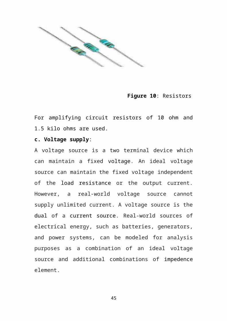
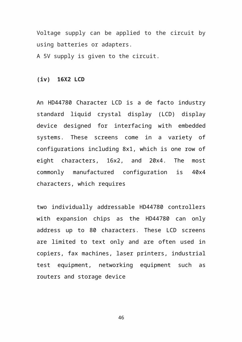
Figure 11: 16X2 LCD
These LCD screens are limited to text only and are often used in
copiers, fax machines, laser printers, industrial test equipment,
networking equipment such as routers and storage devices. Character
LCDs can come with or without backlights, which may be LED,
fluorescent, or electroluminescent.
31
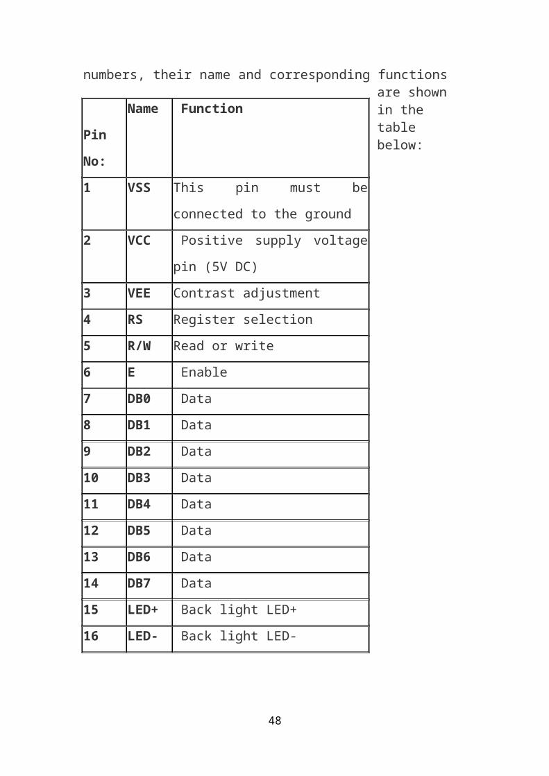
Character LCDs use a standard 14-pin interface and those with backlights have 16 pins. The pin numbers, their name and corresponding functions
are shown in the table below:
32
Pin No:
Name Function
1 VSS This pin must be connected to the
ground
2 VCC Positive supply voltage pin (5V
DC)
3 VEE Contrast adjustment
4 RS Register selection
5 R/W Read or write
6 E Enable
7 DB0 Data
8 DB1 Data
9 DB2 Data
10 DB3 Data
11 DB4 Data
12 DB5 Data
13 DB6 Data
14 DB7 Data
15 LED+ Back light LED+
16 LED- Back light LED-
VEE pin is meant for adjusting the contrast of the LCD display and the
contrast can be adjusted by varying the voltage at this pin. This is done by
connecting one end of a POT to the Vcc (5V), other end to the Ground
and connecting the center terminal (wiper) of the POT to the VEE pin.
See the circuit diagram for better understanding. The JHD162A has two
built in registers namely data register and command register. Data
register is for placing the data to be displayed, and the command register
is to place the commands. The 16×2 LCD module has a set of commands
each meant for doing a particular job with the display. We will discuss in
detail about the commands later. High logic at the RS pin will select the
data register and low logic at the RS pin will select the command register.
If we make the RS pin high and the put a data in the 8 bit data line (DB0
to DB7), the LCD module will recognize it as a data to be displayed. If
we make RS pin low and put a data on the data line, the module will
recognize it as a command. R/W pin is meant for selecting between read
and write modes. High level at this pin enables read mode and low level
at this pin enables write mode. E pin is for enabling the module. A high to
low transition at this pin will enable the module. DB0 to DB7 are the data
pins. The data to be displayed and the command instructions are placed
on these pins. LED+ is the anode of the back light LED and this pin must
be connected to Vcc through a suitable series current limiting resistor.
LED- is the cathode of the back light LED and this pin must be connected
to ground.
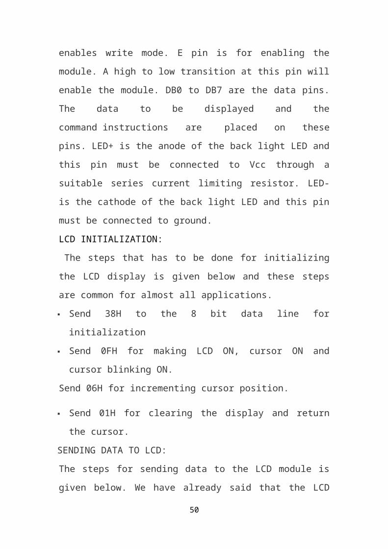
LCD INITIALIZATION:
The steps that has to be done for initializing the LCD display is given
below and these steps are common for almost all applications.
Send 38H to the 8 bit data line for initialization
Send 0FH for making LCD ON, cursor ON and cursor blinking ON.
Send 06H for incrementing cursor position.
33
Send 01H for clearing the display and return the cursor.
SENDING DATA TO LCD:
The steps for sending data to the LCD module is given below. We have
already said that the LCD module has pins namely RS, R/W and E. It is
the logic state of these pins that make the module to determine whether a
given data input is a command or data to be displayed.
Make R/W low.
Make RS=0 if data byte is a command and make RS=1 if the data byte
is a data to be displayed.
Place data byte on the data register.
Pulse E from high to low.
Repeat above steps for sending another data.
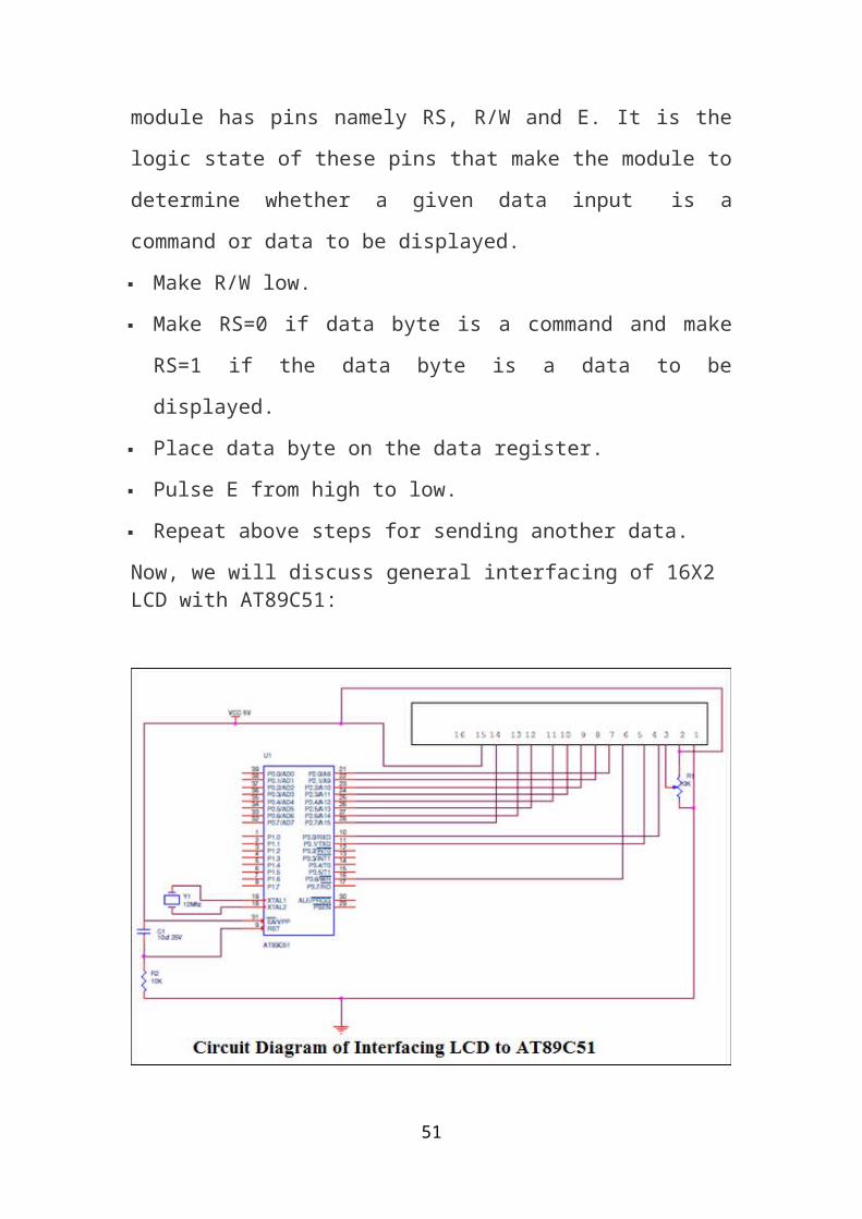
Now, we will discuss general interfacing of 16X2 LCD with AT89C51:
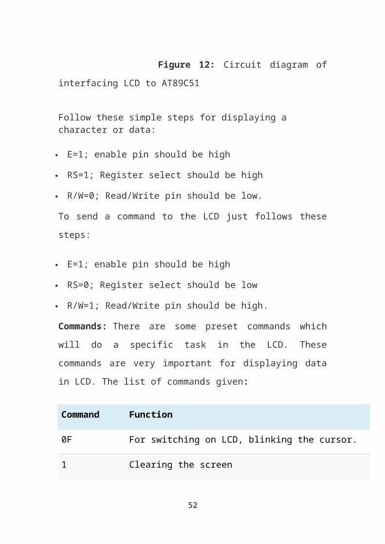
Figure 12: Circuit diagram of interfacing LCD to AT89C51
34
Follow these simple steps for displaying a character or data:
E=1; enable pin should be high
RS=1; Register select should be high
R/W=0; Read/Write pin should be low.
To send a command to the LCD just follows these steps:
E=1; enable pin should be high
RS=0; Register select should be low
R/W=1; Read/Write pin should be high.
Commands: There are some preset commands which will do a specific
task in the LCD. These commands are very important for displaying data
in LCD. The list of commands given:
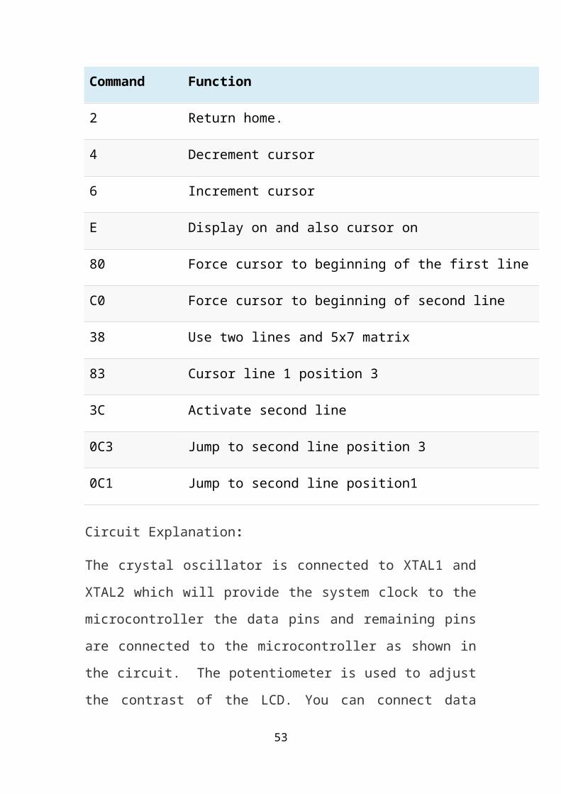
Command Function
0F For switching on LCD, blinking the cursor.
1 Clearing the screen
2 Return home.
4 Decrement cursor
6 Increment cursor
E Display on and also cursor on
80 Force cursor to beginning of the first line
C0 Force cursor to beginning of second line
38 Use two lines and 5x7 matrix
35
Command Function
83 Cursor line 1 position 3
3C Activate second line
0C3 Jump to second line position 3
0C1 Jump to second line position1
Circuit Explanation:
The crystal oscillator is connected to XTAL1 and XTAL2 which will
provide the system clock to the microcontroller the data pins and
remaining pins are connected to the microcontroller as shown in the
circuit. The potentiometer is used to adjust the contrast of the LCD. You
can connect data pins to any port. If you are connecting to port0 then you
have to use pull up registers. The enable, R/W and RS pins are should be
connected to the 10, 11 and 16 (P3.3, P3.4 and P3.5).
Programming LCD to 8951:
Coming to the programming you should follow these steps:
STEP1: Initialization of LCD.
STEP2: Sending command to LCD.
STEP3: Writing the data to LCD.
Initializing LCD: To initialize LCD to the 8051 the following instruction
and commands are to be embed in to the functions
0×38 is used for 8-bit data initialization.
36
0X6H for incrementing the cursor which will help to display another
character in the LCD
0x1H for clearing the LCD.
Sending data to the LCD:
E=1; enable pin should be high
RS=1; Register select should be high for writing the data
Placing the data on the data registers
R/W=0; Read/Write pin should be low for writing the data.
Uses of LCD:
Clocks: Alarm clocks and wall clocks commonly use LCDs to create
simplistic, easy-to-read screens. Modern LCD clocks use the liquid crystal
display to create decorative colors and images behind the date and time.
While the numbers are typically simplistic, LCD alarm clocks often offer
customization options for a stylized display.
Calculators: Calculators use LCDs because of its light and compact
design. This allows the screen to be as large as practical while requiring
little casing space and keeping the weight to a minimum. According to
IEEE, LCD is the most common form of display in modern hand-held
calculator devices.
Television: LCD technology is common in television screens for its light-
weight design and cost effectiveness. According to MSNBC, since 2007,
LCD sales have surpassed that of the traditional vacuum tube televisions
and offer competition to plasma television sales as well. In addition, Flat
Panel TV.org states that an LCD TVs screen lifespan is upward of 60,000
hours, making it more cost effective than other TV screens. LCD
37
4. SOFTWARE DESCRIPTION
Figure 14: Block diagram
The software used for the procedure is KIEL. The software codes used
are as follows:
//Program for Automatic Parking Slot Indicator
//using AT89C51
#include<reg51.h>
sbit slot1=P1^0;
38
sbit slot2=P1^1;
sbit slot3=P1^2;
sbit slot4=P1^3;
sbit led1=P3^0;
sbit led2=P3^1;
sbit led3=P3^2;
sbit led4=P3^3;
sbit rs=P0^0;
sbit rw=P0^1;
sbit en=P0^2;
void delay(int itime)
{
int i,j;
for(i=0;i<=itime;i++)
for(j=0;j<=1275;j++);
}
");
lcdcmd(0x39); void lcdcmd(unsigned char value)
{
rs=0;
rw=0;
en=1;
P2=value;
39
delay(1);
en=0;
}
void lcddata(unsigned char *value)
{
int i;
for(i=0;value[i]!='\0';i++)
{
rs=1;
rw=0;
en=1;
P2=value[i];
delay(1);
en=0;
}
}
void lcdnum(unsigned char slot)
{
rs=1;
rw=0;
en=1;
P2=slot;
delay(1);
en=0;
}
void main()
{
int x;
unsigned char a[4]={'1','2','3','4'};
40
unsigned char b[4]={'1','2','3','4'};
unsigned int c[4];
P3=0x00;
P1=0x00;
lcdcmd(0x08);
delay(1);
lcdcmd(0x38);
delay(1);
lcdcmd(0x0e);
delay(1);
lcdcmd(0x01);
delay(1);
lcdcmd(0x06);
delay(1);
lcdcmd(0x39);
delay(1);
lcddata("Welcome to
lcdcmd(0x80);
lcddata("Automatic Parking Indicator");
delay(500);
lcdcmd(0x01);
lcddata("Initialising.");
delay(50);
lcddata(".");
delay(50);
lcddata(".");
delay(50);
while(1)
{
41
if(slot1==0)
{
led1=1;
delay(1);
c[0]=1;
delay(10);
}
else
{
led1=0;
delay(1);
c[0]=0;
delay(10);
}
If (slot2==0)
{
led2=1;
delay(1);
c[1]=1;
delay(10);
}
else
{
led2=0;
delay(1);
c[1]=0;
delay(10);
}
if(slot3==0)
42
delay(1);
c[2]=1;
delay(10);
}
else
{
led3=0;
delay(1);
c[2]=0;
delay(10);
}
if(slot4==0)
{
led4=1;
delay(1);
c[3]=1;
delay(10);
}
else
{
led4=0;
delay(1);
c[3]=0;
delay(10);
}
lcdcmd(0x01);
lcdcmd(0x0e);
lcddata("Filled:");
delay(50);
43
lcdcmd(0x01);
lcdcmd(0x39);
for(x=0;x<=4;x++)
{
if(c[x]==1)
{
lcdnum(a[x]);
lcddata(",");
delay(50);
}
}
delay(50);
lcdcmd(0x01);
lcdcmd(0x0e);
lcddata("Available:");
delay(50);
lcdcmd(0x01);
lcdcmd(0x39);
for(x=0;x<=4;x++)
{
if(c[x]==0)
{
lcdnum(b[x]);
lcddata(",");
delay(20);
}
}
y: if(P1==0x00)
{
44
P3=0xFF;
lcdcmd(0x01);
lcddata("Parking Full");
delay(50);
lcdcmd(0x01);
goto y;
}
} //while(1) ends here
} //main() ends here
45
5. SCHEMATIC CONNECTIONS
FIGURE 14: Schematic layout
46
The connections are made in Proteus software. The C file id first
compiled in Keil Software and a hex file is created from Keil. The Hex
file is embedded in the microcontroller in the simulation work and also
virtually. In proteus sensors are replaced by switches and data is
displayed by using LED’S and LCD.
In the schematic layout circuit of AT89C51 the ports P1.0 – P1.3 are
connected to the output of the receiver transmitter sensors. These sensors
will detect the coming obstacle and will send information to
microcontroller using these ports. When the sensor is blocked by any
obstacle it will send 1 to the ports i.e it is in off state which indicates that
the car entered the parking area and one of the slots is filled. When there
is no obstacle, the sensors are in on state and will send 0 to the
microcontroller. The pins P3 are connected to the LCD which will
indicate the availability of space in the parking area. If parking is full it
will show that there is no space for incoming vehicle. LED connected to
the port P2 are used as indicator for the empty slots. It shows the
available space for incoming cars.
General circuit of amplifier circuit:
Figure 15: Amplifier circuit
47
Amplifier circuit amplifies the voltage and the output of the circuit is
given to the microcontroller. The input from the IR sensors is given to the
amplifier circuit. Main components of the amplifier circuit are
1. NPN Transistor
2. Resistances of 100 Ohm and 1.5 KiloOhm
3. Sensors
6. ADVANTAGES
Advance car parking is becoming famous day by day. It is far better than the
old methods of parking as it is helpful in many ways. here are some
advantages of advance car parking using slot indicator:
1.Efficiency:
Automatic Car Parking System provides car parking solutions
accommodating maximum cars in minimum space
2. Cost effective:
Automatic Car Parking System improves financial viability of
commercial and residential developments
3. Saves Time: Automatic Car Parking System reduces parking and
retrieval time. Saves time spend in searching for empty parking slots and
48
time spend is searching the parked car. Retrieval on average is 2 to 3
minutes
4.Easy and cost effective maintenance
Automatic Car Parking System is cost effective in terms of maintenance
over the conventional parking systems.
5 Car safety
Automatic Car Parking System provides improved security, safety for the
cars. Cars parked are free from theft and damages that can e caused while
parking and retrieving.
6. Safer for drivers
Drivers collect their cars from secure waiting areas; thus they do not have
to walk through a car park alone and are less vulnerable
7.Environment friendly
Automatic Car Parking System is environment friendly. As the car
engines are shut during the automatic parking process there is no
pollution.
8.Aesthetics
State of the art modular design makes the system look very attractive.
9. Rush
Automatic car parking avoids rush and traffic jams in the parking area as
searching for empty parking slots become easy.
7. USES AND IMPLANTATION IN
VARIOUS CITIES
Automatic car parking can be used in:
Malls
49
Multistory buildings
Cinema halls
Offices
Implantation in cities:
As automatic car parking is very beneficial it is used in many countries of
world. Initially it was developed in Paris, France. Then other countries
had adopted their idea and use this system to make their life easy and
comfortable. America, England, China, Singapore etc. have this
automatic car parking facility. India also have automatic car parking
system in some cities. These cities are Delhi, Chennai and Pune
.
8. FUTURE SCOPE
Advance car parking has many benefits over normal parking system. So
due to its unlimited benefits and very few disadvantages it will become
famous in every city and every town in next few years.
Automatic Car Parking System enables the parking of vehicles, floor after
floor, by displaying the available slots thus reducing the ground space
used. Here any number of cars can be parked according to the
requirement, making the system modernized and a space-saving one.
When a vehicle arrived for parking, there is a chance of probability to
extend this system along with the identity cards .The LCD
displays the empty spaces availability of that particular rack.
Then user has to enter his password, provided the first digit must be the
empty space in which he wishes to park his vehicle thus ensuring
protection. Again if he entered correct password then only the exit
50
gate will be opened for him. If the person
removes another vehicle then the sensors that are provided
beneath every parking place gives a buzzer sound which is being
provided and automatically the exit gate gets closed providing security to
vehicle owner. B y t h i s i m p l e m e n t a t i o n i n t h e c i r c u i t ,
p a r k i n g p r o b l e m i s s o l v e d a n a l s o i t p r e v e n t s vehicle
thefts. Person can also use its credit card to pay parking fee. The
criteria of advance booking of parking slots can also be
implanted to save the time of public.
9. CONCLUSION
By the end of this project
1. Connections and testing in Proteus is studied.
2. Coding and compiling of a C program in Keil u Vision software is
studied.
3. Hardware implementation by connecting Schematic
4. The hardware kit is tested successfully by embedding the C program –
Hex file in the AT89C51 Microcontroller.
5. The operation of microcontroller is analyzed in simulation and
practically.
At the end of this project hence we concluded that automatic car parking
is very beneficial and can be easily implanted.
51
REFERENCES
1. The 8051 microcontroller and embedded system by Muhammad Ali
Mazidi
2. en.wikipedia.org/wiki/Car_Parking_System
3. www.roboticparking.com/robotic_parking_how_it_works.html
4. www.slideshare.net/.../automatic-car-parking-system-16237748
5. en.wikipedia.org/wiki/Automated_parking_system
6. www.scribd.com
7. www.sgrlaw.com › Our Clients › Client Profiles
8.www.studymode.com/.../scope-and-delimitation-in-parking-
systemww.edgefxkits.com/rfid
9.www.eccos.com.hr/.../partneri/.../Skidata._!Brochure._Car_Parks-
EN.pd
10.www.scribd.com/doc/29013195/Automatic-Car-Parkingconcept-
based-paid-car-parking
11. www.projectsof8051.com/automatic-car-parking-indicator-system/
grietinfo.in/projects/MINI/EEE/DOC-A.8-Automatic%20parking.pdf
12. embedded-electronics.blogspot.com/p/at89c51-programming.html
13. www.savepageaspdf.com
14. projectus.freehost7.com
52
APPENDIX A
53
APPENDIX B
54


![Micro Processors & Micro Controllers Lecture Notesgopalmic.weebly.com/uploads/6/0/3/4/6034310/mpi_full_document.pdfMicro Processors & Micro Controllers Lecture Notes (As Per JNTUK-[R07]](https://static.fdocuments.in/doc/165x107/5aa2476a7f8b9a1f6d8d063d/micro-processors-micro-controllers-lecture-processors-micro-controllers-lecture.jpg)