MiCOM H35x - s; E
42
MiCOM H35x H35x/EN GL/C23 Global Documentation
Transcript of MiCOM H35x - s; E

MiCOM H35x
H35x/EN GL/C23
Global Documentation

Global Documentation H35x/EN GL/C23 MiCOM H35x Page 1/38
CONTENTS
1. SAFETY AND HANDLING 5
1.1 Health and safety 5 1.2 Symbols 6 1.3 Installing, commissioning and servicing 6 1.4 De-commissioning and disposal 7 1.5 Technical specifications for safety 8 1.5.1 Protective fuse rating 8 1.5.2 Protective class 8 1.5.3 Installation category 8 1.5.4 Environment 8 1.6 Handling of Electronic Equipment 8 1.7 Packing and Unpacking 9 1.8 Guarantees 9 1.9 Copyrights & Trademarks 10 1.9.1 Copyrights 10 1.9.2 Trademarks 10 1.9.3 Warnings regarding use of Schneider Electric products 10
2. INTRODUCTION 11
2.1 MiCOM Switches Product Range 11 2.2 Naming of MiCOM Ethernet Switches 11 2.3 MiCOM H35x 11
3. FUNCTIONAL DESCRIPTION 12
3.1 MiCOM H35x Product Range 12 3.2 Fast redundant ring capability 12 3.2.1 Self-healing ring principle 12 3.2.2 MiCOM Hx5x Ethernet switch with self-healing ring facilities 13 3.2.3 Schneider Electric Ethernet ring redundancy 13 3.2.4 Performance 14 3.2.5 Benefits 15 3.3 MiCOM H35x functional composition 15 3.4 Power management 15 3.5 Ethernet Port Switching Features 15 3.5.1 10Base Tx and 100Base Tx 15 3.5.2 100Base Fx 15

H35x/EN GL/C23 Global Documentation Page 2/38 MiCOM H35x 3.6 Ethernet Management 16 3.6.1 Address lookup 16 3.6.2 Auto-negotiation and speed-sensing 16 3.6.3 Forwarding 16 3.6.4 Priority tagging 16 3.6.5 SNMP v2 16
4. TECHNICAL DATA 18
4.1 MiCOM H35x Range 18 4.2 CONFORMITY 18 4.3 Ethernet Port Characteristics 18 4.3.1 10/100BaseTx Port 18 4.3.2 100BaseFx Multimode Port (H352) 18 4.3.3 100BaseFx Single Mode Port (H354) 18 4.3.4 100BaseFx Multimode Port (H356, H358) 19 4.3.5 100BaseFx Single Mode Port (H358 ring connector) 19 4.4 General Characteristics 19 4.4.1 Mechanical 19 4.4.2 Auxiliary Power Supply 19 4.4.3 Auxiliary Fault Relay 19 4.4.4 Ethernet Management 20 4.5 Environmental Characteristics 20 4.5.1 Electrical 20 4.5.2 Isolation 20 4.5.3 Climatic 21 4.5.4 Electromagnetic Compatibility 21 4.5.5 Mechanical 22
5. HUMAN MACHINE INTERFACE (HMI) 23
5.1 H352-V2 HMI 23 5.2 H356/H358 HMI 23 5.3 H35x LEDs 24
6. INSTALLATION 25 7. CONNECTION 26
7.1 Connection of the protective conductor (earth) 26 7.2 Cable fitting 26 7.3 Power supply wiring 27 7.4 Fail-safe contacts 28
Global Documentation H35x/EN GL/C23 MiCOM H35x Page 3/38 7.5 Ethernet Connection 29 7.5.1 Ethernet cable type 29 7.5.2 Ethernet optical fiber 29
8. SETTINGS 31
8.1 Dip switch description 31 8.2 Address of the repeater 31 8.2.1 Configuring the address 31 8.2.2 Example: defining address “10” 31 8.3 IP Address of the repeater 32 8.4 Power supply alarm 32 8.5 Label 32
9. MAINTENANCE 33
9.1 Scope 33 9.2 Recommendation before maintenance operations 33 9.3 Maintenance period 33 9.4 Diagnosis facilities 34 9.5 Method of repair 34 9.5.1 Replacing the MiCOM H3xx 34
10. APPLICATIONS 35
10.1 Fiber Optic budget calculations 35 10.1.1 Example 1: between repeaters 36 10.1.2 Example 2: between repeaters with patch panel 36
11. GLOSSARY 37

H35x/EN GL/C23 Global Documentation Page 4/38 MiCOM H35x
FIGURES
FIGURE 1: SELF-HEALING RING MECHANISM 12
FIGURE 2: INTERNAL ARCHITECTURE OF MiCOM HX5X 13
FIGURE 3: NOMINAL REDUNDANT ETHERNET RING ARCHITECTURE WITH MiCOM HX5X SWITCHES 14
FIGURE 4: ETHERNET RING ARCHITECTURE WITH MiCOM HX5X SWITCHES AFTER FAILURE 14
FIGURE 5: MiCOM H352 15
FIGURE 6: H35X MIB STRUCTURE 16
FIGURE 7: 10/100BASETX PORT 18
FIGURE 8: 100BASEFX MULTIMODE PORT (H352) 18
FIGURE 9: 100BASEFX SINGLE MODE PORT (H354) 18
FIGURE 10: 100BASEFX MULTIMODE PORT (H356, H358) 19
FIGURE 11: 100BASEFX SINGLE MODE PORT (H358 RING CONNECTOR) 19
FIGURE 12: H352-V2 HMI 23
FIGURE 13: H356/H358 HMI 23
FIGURE 14: EARTHING CABLE EXAMPLE 26
FIGURE 15: POWER SUPPLY WIRING 27
FIGURE 16: FAIL-SAFE CONTACTS WIRING 28
FIGURE 17: RJ45 CONNECTOR 29
FIGURE 18: ETHERNET OPTICAL FIBER – ST 29
FIGURE 19: ETHERNET OPTICAL FIBER – SC 30
FIGURE 20: DIP SWITCHES 31
FIGURE 21: DIP SWITCHES EXAMPLE 32
FIGURE 22: IP ADDRESS 32
FIGURE 23: MiCOM H35X LABEL 32
FIGURE 24: POWER SUPPLY CONNECTOR 33
FIGURE 25: FIBER BUDGET 35
FIGURE 26: FIBER BUDGET EXAMPLE 35
Global Documentation H35x/EN GL/C23 MiCOM H35x Page 5/38
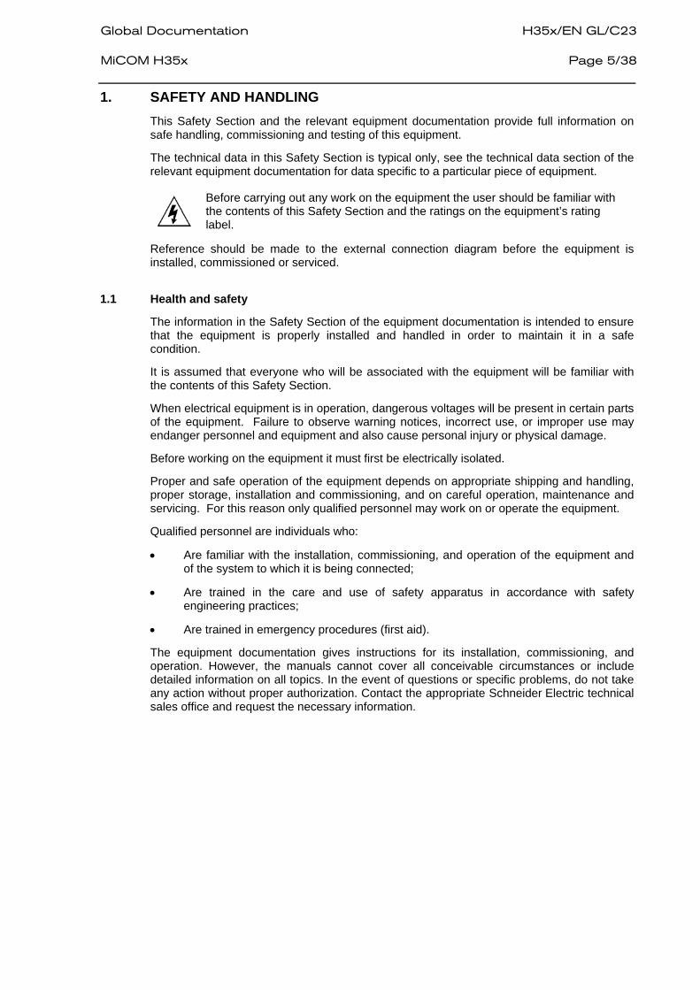
1. SAFETY AND HANDLING This Safety Section and the relevant equipment documentation provide full information on safe handling, commissioning and testing of this equipment.
The technical data in this Safety Section is typical only, see the technical data section of the relevant equipment documentation for data specific to a particular piece of equipment.
Before carrying out any work on the equipment the user should be familiar with the contents of this Safety Section and the ratings on the equipment’s rating label.
Reference should be made to the external connection diagram before the equipment is installed, commissioned or serviced.
1.1 Health and safety
The information in the Safety Section of the equipment documentation is intended to ensure that the equipment is properly installed and handled in order to maintain it in a safe condition.
It is assumed that everyone who will be associated with the equipment will be familiar with the contents of this Safety Section.
When electrical equipment is in operation, dangerous voltages will be present in certain parts of the equipment. Failure to observe warning notices, incorrect use, or improper use may endanger personnel and equipment and also cause personal injury or physical damage.
Before working on the equipment it must first be electrically isolated.
Proper and safe operation of the equipment depends on appropriate shipping and handling, proper storage, installation and commissioning, and on careful operation, maintenance and servicing. For this reason only qualified personnel may work on or operate the equipment.
Qualified personnel are individuals who:
• Are familiar with the installation, commissioning, and operation of the equipment and of the system to which it is being connected;
• Are trained in the care and use of safety apparatus in accordance with safety engineering practices;
• Are trained in emergency procedures (first aid).
The equipment documentation gives instructions for its installation, commissioning, and operation. However, the manuals cannot cover all conceivable circumstances or include detailed information on all topics. In the event of questions or specific problems, do not take any action without proper authorization. Contact the appropriate Schneider Electric technical sales office and request the necessary information.

H35x/EN GL/C23 Global Documentation Page 6/38 MiCOM H35x 1.2 Symbols
For safety reasons the following symbols which may be used on the equipment or referred to in the equipment documentation, should be understood before it is installed or commissioned.
Caution: refer to equipment documentation
Caution: risk of electric shock
Protective Conductor (*Earth) terminal
Functional/Protective Conductor (*Earth) terminal
Note: This symbol may also be used for a Protective Conductor (Earth) terminal if that terminal is part of a terminal block or sub-assembly e.g. power supply.
*NOTE: THE TERM EARTH USED THROUGHOUT THIS TECHNICAL MANUAL IS THE DIRECT EQUIVALENT OF THE NORTH AMERICAN TERM GROUND.
1.3 Installing, commissioning and servicing
Equipment connections Personnel undertaking installation, commissioning or servicing work for this equipment should be aware of the correct working procedures to ensure safety. The equipment documentation should be consulted before installing, commissioning, or servicing the equipment. Terminals exposed during installation, commissioning and maintenance may present a hazardous voltage unless the equipment is electrically isolated. Any disassembly of the equipment may expose parts at hazardous voltage, also electronic parts may be damaged if suitable electrostatic voltage discharge (ESD) precautions are not taken. If there is unlocked access to the rear of the equipment, care should be taken by all personnel to avoid electric shock or energy hazards. The equipment must be connected in accordance with the appropriate connection diagram. Protection Class I Equipment
- Before energizing the equipment it must be earthed using the protective conductor terminal, if provided, or the appropriate termination of the supply plug in the case of plug connected equipment.
- The protective conductor (earth) connection must not be removed since the protection against electric shock provided by the equipment would be lost.
- When the protective (earth) conductor terminal (PCT) is also used to terminate cable screens, etc., it is essential that the integrity of the protective (earth) conductor is checked after the addition or removal of such functional earth connections. For M4 stud PCTs the integrity of the protective (earth) connections should be ensured by use of a locknut or similar.

Global Documentation H35x/EN GL/C23 MiCOM H35x Page 7/38
The recommended minimum protective conductor (earth) wire size is 2.5 mm² (3.3 mm² for North America) unless otherwise stated in the technical data section of the equipment documentation, or otherwise required by local or country wiring regulations. The protective conductor (earth) connection must be low-inductance and as short as possible. Before energizing the equipment, the following should be checked:
- Voltage rating/polarity (rating label/equipment documentation); - Protective fuse rating; - Integrity of the protective conductor (earth) connection (where
applicable); - Voltage rating of external wiring, applicable to the application.
Equipment use If the equipment is used in a manner not specified by the manufacturer, the protection provided by the equipment may be impaired.
Equipment operating conditions The equipment should be operated within the specified electrical and environmental limits.
Insulation and dielectric strength testing Insulation testing may leave capacitors charged up to a hazardous voltage. At the end of each part of the test, the voltage should be gradually reduced to zero, to discharge capacitors, before the test leads are disconnected.
Insertion of modules and PCB cards Modules and PCB cards must not be inserted into or withdrawn from the equipment whilst it is energized, since this may result in damage.
Fiber optic communication Where fiber optic communication devices are fitted, these should not be viewed directly. Optical power meters should be used to determine the operation or signal level of the device.
Cleaning The equipment may be cleaned using a lint-free cloth dampened with clean water, when no connections are energized. Contact fingers of test plugs are normally protected by petroleum jelly, which should not be removed.
1.4 De-commissioning and disposal
De-commissioning The supply input (auxiliary) for the equipment may include capacitors across the supply or to earth. To avoid electric shock or energy hazards, after completely isolating the supplies to the equipment (both poles of any dc supply), the capacitors should be safely discharged via the external terminals prior to de-commissioning.
Disposal It is recommended that incineration and disposal to water courses is avoided. The equipment should be disposed of in a safe manner. Any equipment containing batteries should have them removed before disposal, taking precautions to avoid short circuits. Particular regulations within the country of operation, may apply to the disposal of the equipment.

H35x/EN GL/C23 Global Documentation Page 8/38 MiCOM H35x 1.5 Technical specifications for safety
Unless otherwise stated in the equipment technical manual, the following data is applicable.
1.5.1 Protective fuse rating
The recommended maximum rating of the external protective fuse for equipments is 16A, high rupture capacity (HRC) Red Spot type NIT, or TIA, or equivalent. The protective fuse should be located as close to the unit as possible.
1.5.2 Protective class
IEC 60255-27: 2005 Class I (unless otherwise specified in the EN 60255-27: 2005 equipment documentation). This equipment requires a protective conductor (earth) connection to ensure user safety.
1.5.3 Installation category
IEC 60255-27: 2005 Installation category III (Overvoltage Category III): EN 60255-27: 2005 Distribution level, fixed installation. Equipment in this category is qualification tested at 5 kV peak, 1.2/50 µs, 500 Ω, 0.5 J, between all supply circuits and earth and also between independent circuits.
1.5.4 Environment
The equipment is intended for indoor installation and use only. If it is required for use in an outdoor environment then it must be mounted in a specific cabinet or housing allowing it to meet the requirements of IEC 60529 with the classification of degree of protection IP54 (dust and splashing water protected).
Pollution Degree - Pollution Degree 2 Compliance is demonstrated by reference to safety Altitude - Operation up to 2000m standards.
IEC 60255-27:2005 EN 60255-27: 2005
1.6 Handling of Electronic Equipment
A person’s normal movements can easily generate electrostatic potentials of several thousand volts.
Discharge of these voltages into semiconductor devices when handling circuits can cause serious damage, which often may not be immediately apparent but the reliability of the circuit will have been reduced.
The electronic circuits of Schneider Electric products are immune to the relevant levels of electrostatic discharge when housed in their cases. Do not expose them to the risk of damage by withdrawing modules unnecessarily.
Each module incorporates the highest practical protection for its semiconductor devices. However, if it becomes necessary to withdraw a module, the following precautions should be taken in order to preserve the high reliability and long life for which the equipment has been designed and manufactured.
1. Before removing a module, ensure that you are at the same electrostatic potential as the equipment by touching the case.
2. Handle the module by its front-plate, frame, or edges of the printed circuit board. Avoid touching the electronic components, printed circuit track or connectors.
3. Do not pass the module to any person without first ensuring that you are both at the same electrostatic potential. Shaking hands achieves equipotential.
4. Place the module on an antistatic surface, or on a conducting surface that is at the same potential as you.
5. Store or transport the module in a conductive bag.

Global Documentation H35x/EN GL/C23 MiCOM H35x Page 9/38
More information on safe working procedures for all electronic equipment can be found in IEC 60147-0F and BS5783.
If you are making measurements on the internal electronic circuitry of any equipment in service, it is preferable that you are earthed to the case with a conductive wrist strap.
Wrist straps should have a resistance to ground between 500k – 10M Ohms. If a wrist strap is not available you should maintain regular contact with the case to prevent the build up of static. Instruments used for making measurements should be earthed to the case whenever possible.
Schneider Electric strongly recommends that detailed investigations on the electronic circuitry, or modification work, should be carried out in a Special Handling Area such as described in IEC 60147-0F or BS5783.
1.7 Packing and Unpacking
All MiCOM Hxxx devices are packaged separately in their own cartons and shipped inside outer packaging. Use special care when opening the cartons and unpacking the device, and do not use force. In addition, make sure to remove from the inside carton the supporting documents supplied with each individual device and the type identification label.
The design revision level of each module included with the device in its as-delivered condition can be determined from the list of components. This list should be carefully saved.
After unpacking the device, inspect it visually to make sure it is in proper mechanical condition.
If the MiCOM Hxxx device needs to be shipped, both inner and outer packaging must be used. If the original packaging is no longer available, make sure that packaging conforms to ISO 2248 specifications for a drop height ≤0.8m.
1.8 Guarantees
The media on which you received Schneider Electric software is guaranteed not to fail executing programming instructions, due to defects in materials and workmanship, for a period of 90 days from date of shipment, as evidenced by receipts or other documentation. Schneider Electric will, at its option, repair or replace software media that do not execute programming instructions if Schneider Electric receive notice of such defects during the warranty period. Schneider Electric does not guarantee that the operation of the software shall be uninterrupted or error free.
A Return Material Authorization (RMA) number must be obtained from the factory and clearly marked on the package before any equipment acceptance for guarantee work. Schneider Electric will pay the shipping costs of returning to the owner any parts that are covered by warranty.
Schneider Electric believe that the information in this document is accurate. The document has been carefully reviewed for technical accuracy. In the event that technical or typographical errors exist, Schneider Electric reserves the right to make changes to subsequent editions of this document without prior notice to holders of this edition. The reader should consult Schneider Electric if errors are suspected. In no event shall Schneider Electric be liable for any damages arising from or related to this document or the information contained in it.
Except as specified herein, Schneider Electric makes no guarantees, express or implied and specifically disclaims any guarantee of merchantability or suitability for a particular purpose. Customer's rights to recover damages caused by fault or negligence on the part Schneider Electric shall therefore be limited to the amount paid by the customer. Schneider Electric will not be liable for damages resulting from loss of data, profits, use of products or incidental or consequential damages even if advised of the possibility thereof. This limitation of the liability of Schneider Electric will apply regardless of the form of action, whether in contract or tort, including negligence. Any action against Schneider Electric must be brought within one year after the cause of action accrues. Schneider Electric shall not be liable for any delay in performance due to causes beyond its reasonable control. The warranty provided herein does not cover damages, defects, malfunctions, or service failures caused by owner's failure to follow Schneider Electric installation, operation, or maintenance instructions, owner's modification of the product; owner's abuse, misuse, or negligent acts;

H35x/EN GL/C23 Global Documentation Page 10/38 MiCOM H35x
and power failure or surges, fire, flood, accident, actions of third parties, or other events outside reasonable control.
1.9 Copyrights & Trademarks
1.9.1 Copyrights
Under the copyright laws, this publication may not be reproduced or transmitted in any form, electronic or mechanical, including photocopying, recording, storing in an information retrieval system, or translating, in whole or in part, without the prior written consent of Schneider Electric.
1.9.2 Trademarks
PACiS, PACiS SCE, PACiS ES, PACiS OI, PACiS SMT, Schneider Electric, pacis.biz and pacis.com - are trademarks of Schneider Electric. Product and company names mentioned herein are trademarks or trade names of their respective companies.
1.9.3 Warnings regarding use of Schneider Electric products
Schneider Electric products are not designed with components and testing for a level of reliability suitable for use in connection with surgical implants or as critical components in any life support systems whose failure to perform can reasonably be expected to cause significant injuries to a human.
In any application, including the above reliability of operation of the software products can be impaired by adverse factors, including - but not limited to - fluctuations in electrical power supply, computer hardware malfunctions, computer operating system malfunctions, software suitability, suitability of compilers and development software used to develop an application, installation errors, software and hardware compatibility problems, malfunctions or failures of electronic monitoring or control devices, transient failures of electronic systems (hardware and/or software), unanticipated uses or misuses, or errors by the user or application designer (adverse factors such as these are collectively termed "System failures").
Any application where a system failure would create a risk of harm to property or persons (including the risk of bodily injuries and death) should not be reliant solely upon one form of electronic system due to the risk of system failure to avoid damage, injury or death, the user or application designer must take reasonable steps to protect against system failure, including - but not limited - to back-up or shut-down mechanisms, not because the end-user's system is customized and differs from Schneider Electric testing platforms but also because a user or application designer may use Schneider Electric products in combination with other products. These actions cannot be evaluated or contemplated by Schneider Electric. Thus, the user or application designer is ultimately responsible for verifying and validating the suitability of Schneider Electric products whenever they are incorporated in a system or application, even without limitation of the appropriate design, process and safety levels of such system or application.

Global Documentation H35x/EN GL/C23 MiCOM H35x Page 11/38
2. INTRODUCTION The MiCOM Ethernet range is designed to deal with the needs of a wide range of electric plants. Emphasis has been placed on strong compliance with standards, scalability, modularity and open architecture.
Theses features facilitate the use of MiCOM products in several applications, from the most basic to the most demanding. They also ensure interoperability with existing components.
Schneider Electric philosophy is to provide a range of Ethernet products such as switches, taking into account the compulsory requirements of electrical substations, including power supply and immunity to environmental constraints.
It also provides solutions to specific requirements such as network redundancy management.
Each of these products can be used independently, or can be integrated to form a PACiS system, which is a Digital Control System (DCS).
2.1 MiCOM Switches Product Range
Driven by calls from all over the world for advanced substation applications for Automation control and monitoring, Schneider Electric is committed to provide a comprehensive range of Ethernet-based products that respond to our customers' needs.
Standard Ethernet products rarely meet the constraints of electrical plants: environmental, power supply, redundancy, etc.
The new MiCOM Hxxx series has been specifically tailored to respond to all of these requirements, and is compatible with the PACiS system. The MiCOM Hxxx range is designed to address different kinds of architectures and installations.
The MiCOM H series is split into three major ranges:
• MiCOM Hx4x Ethernet Switches designed for Simple Ethernet Star architecture
• MiCOM Hx5x Ethernet Switches designed for Redundant Optical Ring architecture with fast Self-Healing technology
• MiCOM Hx6x Ethernet Switches designed for Dual Ethernet Star architecture with Dual Homing technology
2.2 Naming of MiCOM Ethernet Switches
The Ethernet devices naming convention depends on its mechanical features and the number of copper or optical ports.
The existing devices are:
• MiCOM H1xx PCI Board (the power supply is from the PCI BUS)
• MiCOM H3xx DIN mounting case and Redundant power supply
• MiCOM H6xx 19’’ Rack with up to 4 switches and Redundant power supply
2.3 MiCOM H35x
The MiCOM H35x range is a set of standalone switches, embedded with the Self Healing Mechanism to provide redundancy.
The MiCOM H35x range relies on managed switches that are easy to install and operate, designed to be implemented in an electrical plant environment (IEC 61000-4 & 60255-5).
On the media side, MiCOM H35x supports 10BaseT, 100BaseTX and 100BaseFX as specified by the IEEE 802.3 standard.
The MiCOM H35x is a plug-and-play device. It can run with the factory settings. However, to adapt the switch to your application, you only need to configure the switch number using the DIP switches. (see chapter 8: Settings).
H35x/EN GL/C23 Global Documentation Page 12/38 MiCOM H35x
3. FUNCTIONAL DESCRIPTION The MiCOM H35x is designed to be an Ethernet switch with a DIN RAIL mounting.
3.1 MiCOM H35x Product Range
The MiCOM H35x range is dedicated to ultra fast redundant Ethernet rings, and is defined by the type of Ethernet connector. All the MiCOM H35x equipment range has at least two copper connections via RJ45 connectors, with speed automatically adjusted by the external emitters to 10 or 100 Mbps.
Ethernet copper links are limited in distance and subject to interference. The redundant Ethernet ring is based on optical inter-switch connection. The user has the choice between using Multimode Fiber optic for short distances, or Single mode Fiber Optic for long distances.
The table below describes the MICOM H35x range, detailing the connectivity used.
Model Description Connectors
MiCOM H 352 Fast Ethernet industrial switch Multimode 1310 nm
6 x RJ45 2 x ST (for Ring)
MiCOM H 354 Fast Ethernet industrial switch Single mode 1310 nm
6 x RJ45 2 x SC
MiCOM H 356 Fast Ethernet industrial switch Multimode 1310 nm
2 x LC (for Ring Multimode) 4 x LC - Multimode 2 RJ45
MiCOM H 358 Fast Ethernet industrial switch Single mode 1310 nm
2 x LC (for Ring Single mode) 4 x LC - Multimode 2 RJ45
3.2 Fast redundant ring capability
3.2.1 Self-healing ring principle
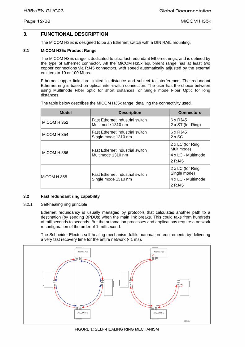
Ethernet redundancy is usually managed by protocols that calculates another path to a destination (by sending BPDUs) when the main link breaks. This could take from hundreds of milliseconds to seconds. But the automation processes and applications require a network reconfiguration of the order of 1 millisecond.
The Schneider Electric self-healing mechanism fulfils automation requirements by delivering a very fast recovery time for the entire network (<1 ms).
S0204ENa
MiCOM H35
MiCOM H15
MiCOM H35
MiCOM H15
FIGURE 1: SELF-HEALING RING MECHANISM

Global Documentation H35x/EN GL/C23 MiCOM H35x Page 13/38 3.2.2 MiCOM Hx5x Ethernet switch with self-healing ring facilities
The MiCOM Hx5x is a standard IEEE802.3 Ethernet switch enhanced with the self-healing manager (SHM). The diagram below shows the internal architecture of such a device.
Ethernet 100BaseFx
SWITCH
SHM Self-healing ring
manager
PHY
Ethernet Ports 10/100 Base TX
FLASH
Port MII
No. Fail-safe output relays
PHY
To 2 Optical Ring
Primary ring
Secondary ring
Ring EpRs
S0205ENb
Ring RpEs
FIGURE 2: INTERNAL ARCHITECTURE OF MiCOM HX5X
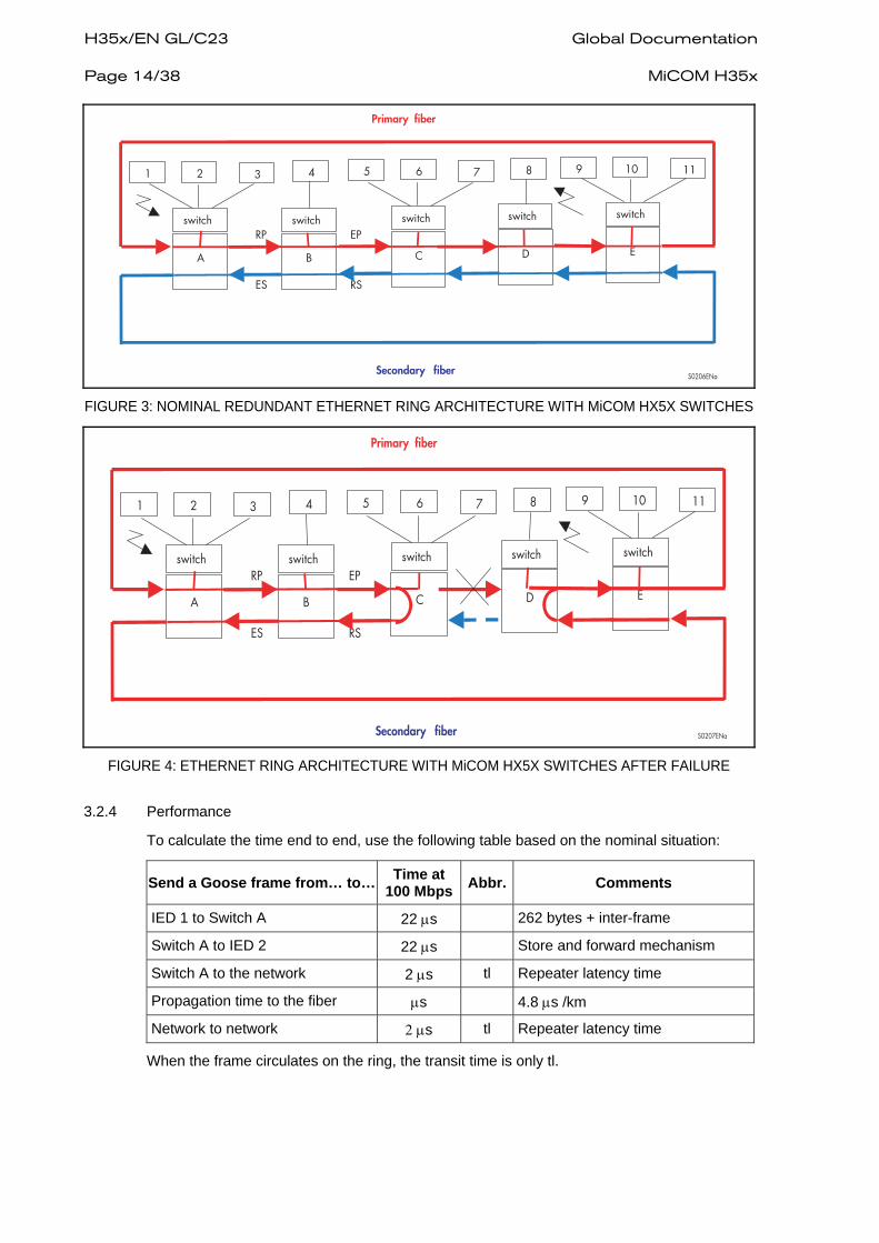
3.2.3 Schneider Electric Ethernet ring redundancy
The SHM functions manage the ring. If the connection between two devices is broken the network continues to run correctly.
Normally Ethernet packets travel on the primary fiber in the same direction, and only a control frame (4 bytes) is sent every 5 µs on the secondary fiber in the opposite direction.
If the link is down, both SHMs immediately start the network self-healing. On one side of the break, received messages are no longer sent to the primary fiber but are sent to the secondary fiber. On the other side of the break, messages received on the secondary fiber are sent to the primary fiber and the new topological loop is closed in less than 1 ms.
It is therefore possible to extend the number of devices, or the size of a substation without stopping the network. The loop is opened and new equipment is connected (which closes the loop).
To increase reliability, some specific mechanisms are used:
• The quality of transmission is monitored. Each frame (Ethernet packet or control frame) is controlled by the SHM. If a high error rate is detected, self-healing starts and the fault is eliminated.
• Even if there is no traffic on the primary link, the secondary link is still supervised by sending out control frames every 5 µs.
Initially, the network architecture is as shown on figure 3.
H35x/EN GL/C23 Global Documentation Page 14/38 MiCOM H35x
S0206ENa
EP
RS
RP
ES
Primary fiber
Secondary fiber
A B C D E
1 2 3 5 6 7 9 10 1184
switch switch switch switch switch
FIGURE 3: NOMINAL REDUNDANT ETHERNET RING ARCHITECTURE WITH MiCOM HX5X SWITCHES
S0207ENa
EP
RS
RP
ES
Primary fiber
Secondary fiber
A B C D E
1 2 3 5 6 7 9 10 1184
switch switch switch switch switch
FIGURE 4: ETHERNET RING ARCHITECTURE WITH MiCOM HX5X SWITCHES AFTER FAILURE
3.2.4 Performance
To calculate the time end to end, use the following table based on the nominal situation:
Send a Goose frame from… to… Time at 100 Mbps Abbr. Comments
IED 1 to Switch A 22 μs 262 bytes + inter-frame
Switch A to IED 2 22 μs Store and forward mechanism
Switch A to the network 2 μs tl Repeater latency time
Propagation time to the fiber μs 4.8 μs /km
Network to network 2 μs tl Repeater latency time
When the frame circulates on the ring, the transit time is only tl.

Global Documentation H35x/EN GL/C23 MiCOM H35x Page 15/38 3.2.5 Benefits
• Ultra fast ring redundancy capability (<1 ms reconfiguration)
• Ultra fast propagation in the ring
• Specific frame control mechanism (store and forward)
• Ring management
• Watchdog relay for supervision
3.3 MiCOM H35x functional composition
The figure below shows the MiCOM H35x main functional blocks.
FIGURE 5: MiCOM H352
The central part manages the switching of up to eight Ethernet links. A FLASH Memory stores the switching algorithm and manages the minimum parameters of the Ethernet switching algorithm.
The board has two to six copper connections and two to six optical connections (multi mode or single mode).
LEDs and alarm contacts are defined to check that the product operates correctly.
A redundant power supply provides the device with AC and/or DC voltage; the supported ranges are the most common in electrical plants.
3.4 Power management
If a cable is not connected to a port, most of the circuitry for that port is disabled to save power.
3.5 Ethernet Port Switching Features
Due to auto-negotiation, MiCOM H35x automatically determines the speed of its transmission layer, 10/100 Mbps, half or full duplex.
3.5.1 10Base Tx and 100Base Tx
The copper ports are half/full duplex and auto-sense the transmission speed. They will auto-negotiate with the connected device to determine the optimal speed. When the connected device is only capable of transmitting at 10 Mbps, the MiCOM H35x follows at 10 Mbps.
3.5.2 100Base Fx
The fiber optic ports are full duplex at 100 Mbps.

H35x/EN GL/C23 Global Documentation Page 16/38 MiCOM H35x 3.6 Ethernet Management
3.6.1 Address lookup
Each Ethernet device inserts its unique “MAC address” into each message it sends. The port on the MiCOM H35x used for a given MAC address is automatically learnt when a frame is received from that address.
Once an address is learnt, the MiCOM H35x will forward frames to the appropriate port.
Up to 1024 MAC addresses can be stored and monitored at any time.
3.6.2 Auto-negotiation and speed-sensing
All six RJ45 ports of the MiCOM H352/354 independently support auto-negotiation for speeds in the 10BaseT and 100BaseTx modes. Operation is according to the IEEE 802.3u standard.
3.6.3 Forwarding
MiCOM H35x supports the store and forward mechanism. MiCOM H35x forwards messages with known addresses to the appropriate port. Messages with unknown addresses, broadcast messages and multicast messages are forwarded out to all ports except the source port.
3.6.4 Priority tagging
802.1p priority is enabled on all ports.
3.6.5 SNMP v2
Simple Network Management Protocol is the network protocol developed to manage devices in an IP network. SNMP v2 relies on a Management Information Base (MIB) that contains information about parameters to supervise. A MIB's format is a tree structure, with each node identified by a numerical Object IDentifier (OID). Each OID identifies a variable that can be read or set via SNMP with the appropriate software. The information in MIBs is standardized.
3.6.5.1 H35x MIB Structure
The SNMP MIB consists of distinct OIDs, each of which refers to a defined collection of specific information used to manage devices on the Schneider Electric ring. The Schneider Electric MIB uses three types of OID.
System:
Address Name 0 Ccitt 1 ISO 3 Org 6 DOD 1 Internet 2 mgmt 1 Mib-2 1 sys 1 sysDescr Schneider Electric repeater 3 sysUpTime xday yh:zm:zzs:yyms 4 sysName
FIGURE 6: H35X MIB STRUCTURE

Global Documentation H35x/EN GL/C23 MiCOM H35x Page 17/38
RMON:
Address Name 0 Ccitt 1 ISO 3 Org 6 DOD 1 Internet 2 mgmt 1 Mib-2 16 Rmon 1 stat 1 etherstat 1 9 Port number (*) 10 etherStatsIndex etherStatsUndersizePkts 12 etherStatsIndex etherStatsOversizePkts 13 etherStatsIndex etherStatsJabbers 14 etherStatsIndex etherStatsCollisions 15 etherStatsIndex etherStatsPkts64Octets 16 etherStatsIndex etherStatsPkts65to127Octets 17 etherStatsIndex etherStatsPkts128to255Octets 18 etherStatsIndex etherStatsPkts256to511Octets 19 etherStatsIndex
etherStatsPkts512to1023Octets
*Port number: 1 to 6 for the RJ45, port 7 management, port 8 ring
3.6.5.2 SNMP Software
Various “SNMP Client software” tools can be used with the MiCOM H35x range. Schneider Electric does not provide such tools.
Any MIB Browser Software performing the basic SNMP operations (such as GET, GETNEXT, GETRESPONSE…) can work with the MiCOM H range.
H35x/EN GL/C23 Global Documentation Page 18/38 MiCOM H35x
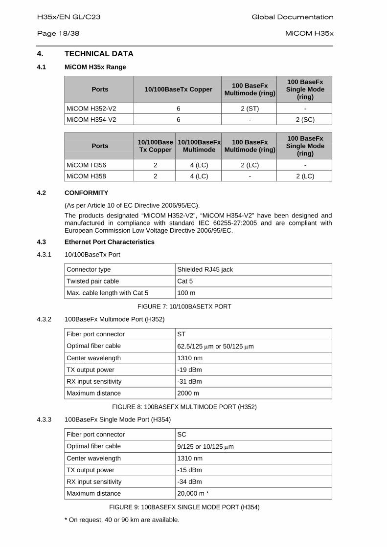
4. TECHNICAL DATA 4.1 MiCOM H35x Range
Ports 10/100BaseTx Copper 100 BaseFx Multimode (ring)
100 BaseFx Single Mode
(ring)
MiCOM H352-V2 6 2 (ST) -
MiCOM H354-V2 6 - 2 (SC)
Ports 10/100BaseTx Copper
10/100BaseFx Multimode
100 BaseFx Multimode (ring)
100 BaseFx Single Mode
(ring)
MiCOM H356 2 4 (LC) 2 (LC) -
MiCOM H358 2 4 (LC) - 2 (LC) 4.2 CONFORMITY
(As per Article 10 of EC Directive 2006/95/EC). The products designated “MiCOM H352-V2”, “MiCOM H354-V2” have been designed and manufactured in compliance with standard IEC 60255-27:2005 and are compliant with European Commission Low Voltage Directive 2006/95/EC.
4.3 Ethernet Port Characteristics
4.3.1 10/100BaseTx Port
Connector type Shielded RJ45 jack
Twisted pair cable Cat 5
Max. cable length with Cat 5 100 m
FIGURE 7: 10/100BASETX PORT
4.3.2 100BaseFx Multimode Port (H352)
Fiber port connector ST
Optimal fiber cable 62.5/125 μm or 50/125 μm
Center wavelength 1310 nm
TX output power -19 dBm
RX input sensitivity -31 dBm
Maximum distance 2000 m
FIGURE 8: 100BASEFX MULTIMODE PORT (H352)
4.3.3 100BaseFx Single Mode Port (H354)
Fiber port connector SC
Optimal fiber cable 9/125 or 10/125 μm
Center wavelength 1310 nm
TX output power -15 dBm
RX input sensitivity -34 dBm
Maximum distance 20,000 m *
FIGURE 9: 100BASEFX SINGLE MODE PORT (H354)
* On request, 40 or 90 km are available.
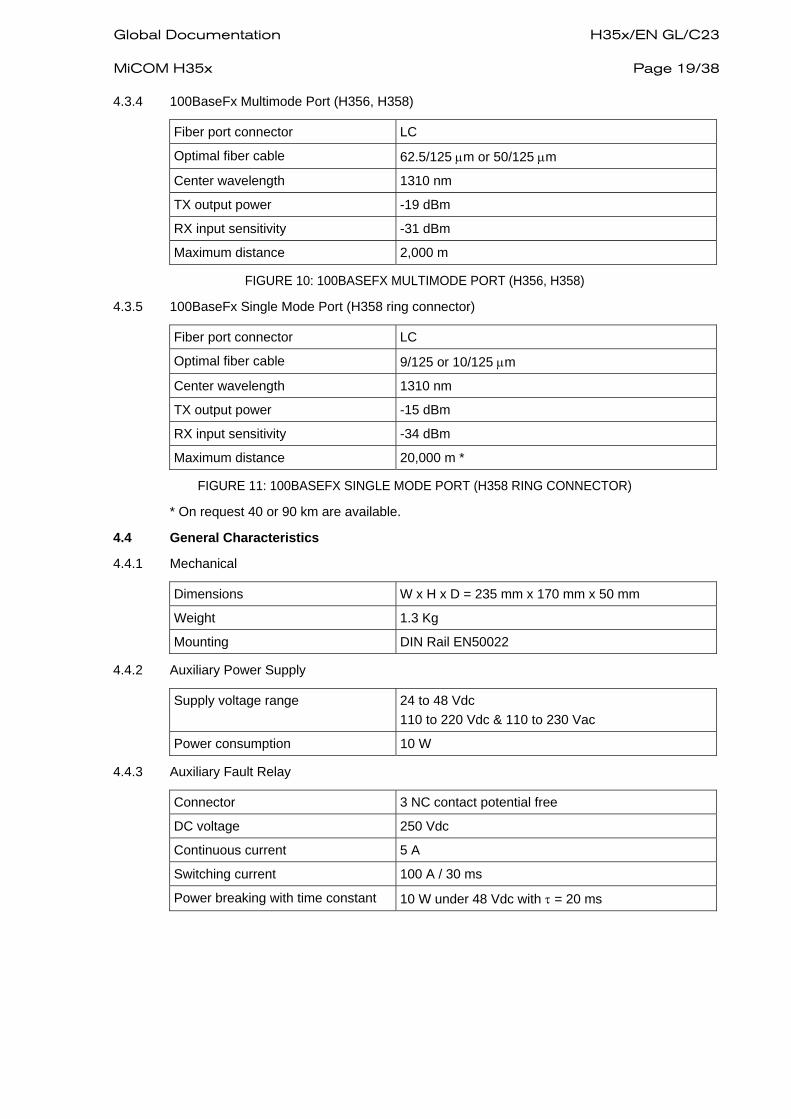
Global Documentation H35x/EN GL/C23 MiCOM H35x Page 19/38 4.3.4 100BaseFx Multimode Port (H356, H358)
Fiber port connector LC
Optimal fiber cable 62.5/125 μm or 50/125 μm
Center wavelength 1310 nm
TX output power -19 dBm
RX input sensitivity -31 dBm
Maximum distance 2,000 m
FIGURE 10: 100BASEFX MULTIMODE PORT (H356, H358)
4.3.5 100BaseFx Single Mode Port (H358 ring connector)
Fiber port connector LC
Optimal fiber cable 9/125 or 10/125 μm
Center wavelength 1310 nm
TX output power -15 dBm
RX input sensitivity -34 dBm
Maximum distance 20,000 m *
FIGURE 11: 100BASEFX SINGLE MODE PORT (H358 RING CONNECTOR)
* On request 40 or 90 km are available.
4.4 General Characteristics
4.4.1 Mechanical
Dimensions W x H x D = 235 mm x 170 mm x 50 mm
Weight 1.3 Kg
Mounting DIN Rail EN50022
4.4.2 Auxiliary Power Supply
Supply voltage range 24 to 48 Vdc
110 to 220 Vdc & 110 to 230 Vac
Power consumption 10 W
4.4.3 Auxiliary Fault Relay
Connector 3 NC contact potential free
DC voltage 250 Vdc
Continuous current 5 A
Switching current 100 A / 30 ms
Power breaking with time constant 10 W under 48 Vdc with τ = 20 ms

H35x/EN GL/C23 Global Documentation Page 20/38 MiCOM H35x 4.4.4 Ethernet Management
Standards IEEE802.3, 802.3u, 802.3x, 802.1p
Forwarding mode Store and forward
Memory bandwidth 2 Gbps
MAC Address 1K
Address learning Automatic
Broadcast storm protection Limited to 5%
Illegal frame Dropped per 802.3
Late collision Dropped after 512 bit times
Latency 4 μs measured at 75% load between two ports at 100 Mbs
4.5 Environmental Characteristics
4.5.1 Electrical
Type Test Name Conditions Type Test Standard
Voltage tolerance DC -20 to + 20% AC -20 to + 20%
IEC 60255-6
DC Supply interruption 0.88 Vmin for 2 to 100 ms IEC 60255-11
AC Supply interruption 0.4 Vn for 10 to 1000 ms IEC 61000–4-11
AC Supply Main frequency fluctuation
44 to 66 Hz IEC 60255-6
DC Supply Overvoltage 1.32 Vn 100 ms IEC 60255-6
DC Supply Inrush current HR46-R-01-4 DICOT
DC Supply Ripple 15% Un 100 Hz IEC61000-4-17
Overcurrent protection Non-changeable fuse
4.5.2 Isolation
Type Test Name Conditions Type Test Standard
Dielectric strength Aux. Power RJ45 ports
3 kVdc for 1 minute 1.5 kVdc for 1 minute
IEC 60255-5
Insulation resistance 100 MΩ at 500 V IEC 60255-5
Impulse voltage 5 kV common mode 1 kV differential mode
IEC 60255-5

Global Documentation H35x/EN GL/C23 MiCOM H35x Page 21/38 4.5.3 Climatic
Type Test Name Conditions Type Test Standard
Extended dry heat – Operating
Test Ca: +55 °C / 20d, +70 °C 24h
IEC 60068-2-2 / 1993
Cold Test - Operating Test Ab: -40 °C / 96h IEC 60068-2-1 / 1993
Cold Test - Storage Test Ad: -40 °C / 96h Powered On at –25 °C (for information) Powered On at –40 °C (for information)
IEC60068-2-1 / 1993
Dry Heat Test – Operating +70 °C / 24h IEC 60068-2-2 / 1993
Dry Heat Test – Storage Test Bd: +70 °C / 96h Powered On at +70 °C
IEC 60068-2-1 / 1993
Humid heat Test - Operating 40 °C, 93% RH, 10 day NFC 20-703 / 1986
Enclosure Protection IP = 20 IEC 60529 4.5.4 Electromagnetic Compatibility
Type Test Name Conditions Type Test Standard
Electrostatic discharge Class 4: 8 kV contact / 15 kV air
IEC 60255-22-2 IEC 61000-4-2 /2001
Radio frequency impulse Class 3: 10 V/m – 80 to 1000 MHz & spot tests 35 V/m – 25 to 1000 MHz
IEC 60255-22-3 IEC 61000-4-3 / 2002 IEEE C37.90.2
Fast transient burst Class 4: 4 kV – 2.5 kHz (CM)
IEC 60255-22-4 IEC 61000-4-4 / 2001 IEEE C37.90.1
Surge Immunity Class 4: 4 kV (CM) – 2 kV (DM)
IEC 61000-4-5 / 2001
High frequency conducted immunity
Class 3: 10 V, 0.15 – 80 MHz
IEC 61000-4-6 / 2001
Power Frequency Magnetic Field Immunity
Class 5: 100 A/m 1000 A/m
IEC 61000-4-8 / 2001
Pulse Magnetic Field Immunity
Class 5: 1000 A/m IEC 61000-4-9 / 2001
Damped oscillatory magnetic field immunity
Class 5: 100 kHz & 1 MHz – 100 A/m
IEC 61000-4-10 /2000
Oscillatory waves immunity Class 4: 2.5 kV (CM) – 1 kV (DM)
IEC 61000-4-12 /2001
Conducted emission Gr. I, class A and B: from 0.15 to 30 MHz
EN 55022 / 2003
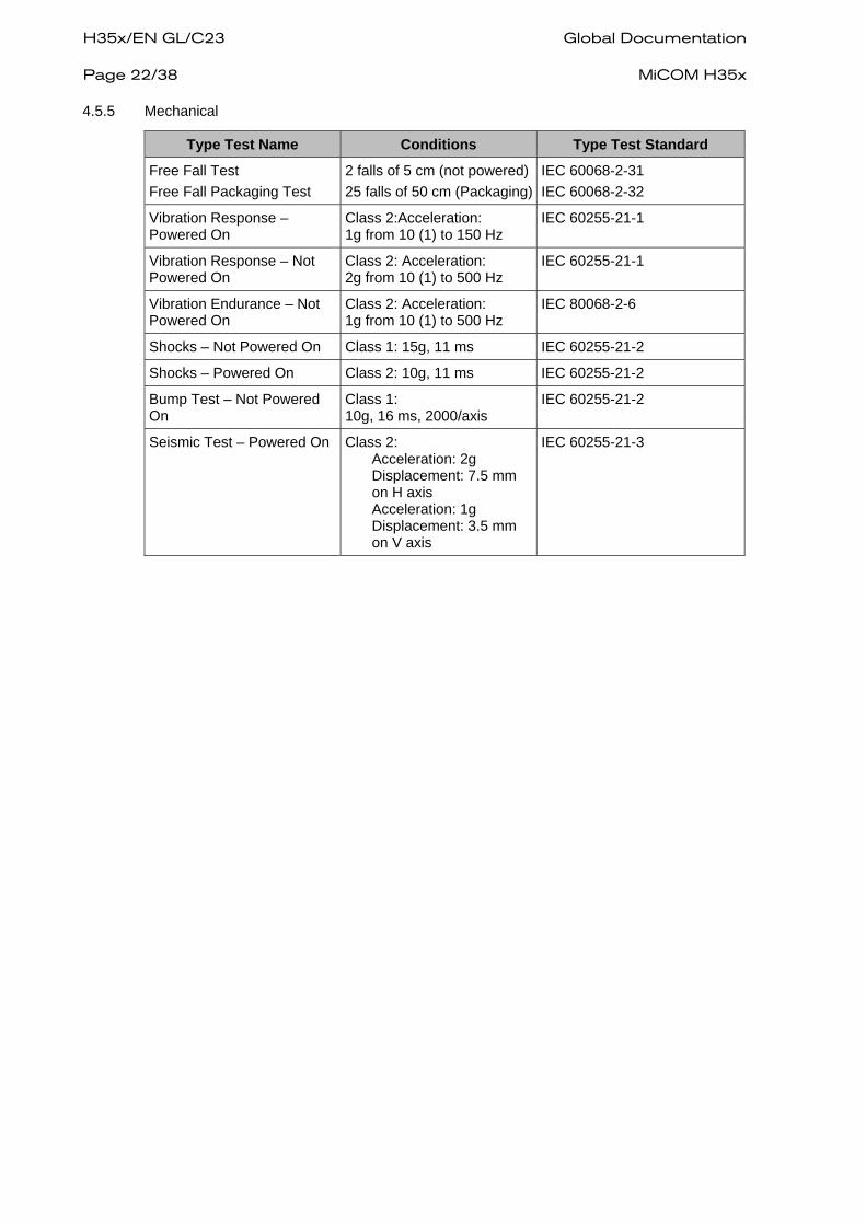
H35x/EN GL/C23 Global Documentation Page 22/38 MiCOM H35x 4.5.5 Mechanical
Type Test Name Conditions Type Test Standard
Free Fall Test Free Fall Packaging Test
2 falls of 5 cm (not powered)25 falls of 50 cm (Packaging)
IEC 60068-2-31 IEC 60068-2-32
Vibration Response – Powered On
Class 2:Acceleration: 1g from 10 (1) to 150 Hz
IEC 60255-21-1
Vibration Response – Not Powered On
Class 2: Acceleration: 2g from 10 (1) to 500 Hz
IEC 60255-21-1
Vibration Endurance – Not Powered On
Class 2: Acceleration: 1g from 10 (1) to 500 Hz
IEC 80068-2-6
Shocks – Not Powered On Class 1: 15g, 11 ms IEC 60255-21-2
Shocks – Powered On Class 2: 10g, 11 ms IEC 60255-21-2
Bump Test – Not Powered On
Class 1: 10g, 16 ms, 2000/axis
IEC 60255-21-2
Seismic Test – Powered On Class 2: Acceleration: 2g Displacement: 7.5 mm on H axis Acceleration: 1g Displacement: 3.5 mm on V axis
IEC 60255-21-3
Global Documentation H35x/EN GL/C23 MiCOM H35x Page 23/38
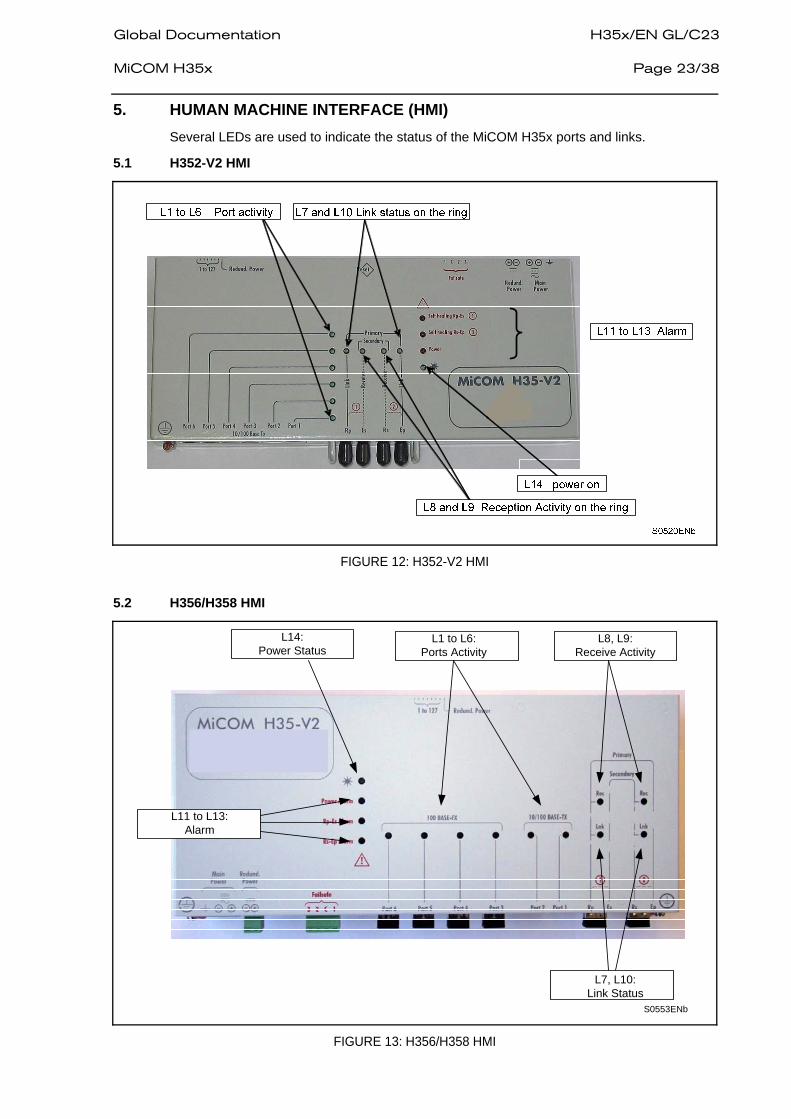
5. HUMAN MACHINE INTERFACE (HMI) Several LEDs are used to indicate the status of the MiCOM H35x ports and links.
5.1 H352-V2 HMI
FIGURE 12: H352-V2 HMI
5.2 H356/H358 HMI
L14:Power Status
L1 to L6:Ports Activity
L8, L9:Receive Activity
L7, L10:Link Status
L11 to L13:Alarm
S0553ENb
FIGURE 13: H356/H358 HMI
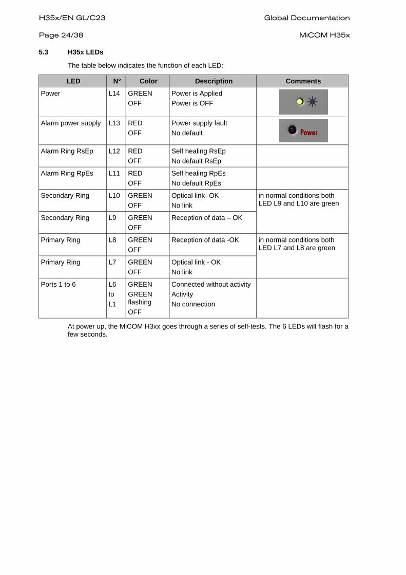
H35x/EN GL/C23 Global Documentation Page 24/38 MiCOM H35x 5.3 H35x LEDs
The table below indicates the function of each LED:
LED N° Color Description Comments
Power L14 GREEN OFF
Power is Applied Power is OFF
Alarm power supply L13 RED
OFF Power supply fault No default
Alarm Ring RsEp L12 RED
OFF Self healing RsEp No default RsEp
Alarm Ring RpEs L11 RED OFF
Self healing RpEs No default RpEs
Secondary Ring L10 GREEN OFF
Optical link- OK No link
Secondary Ring L9 GREEN OFF
Reception of data – OK
in normal conditions both LED L9 and L10 are green
Primary Ring L8 GREEN OFF
Reception of data -OK
Primary Ring L7 GREEN OFF
Optical link - OK No link
in normal conditions both LED L7 and L8 are green
Ports 1 to 6 L6 to L1
GREEN GREEN flashing OFF
Connected without activity Activity No connection
At power up, the MiCOM H3xx goes through a series of self-tests. The 6 LEDs will flash for a few seconds.

Global Documentation H35x/EN GL/C23 MiCOM H35x Page 25/38
6. INSTALLATION The MiCOM H35x can be easily mounted on a standard DIN Rail.
S0
55
4E
Na

H35x/EN GL/C23 Global Documentation Page 26/38 MiCOM H35x
7. CONNECTION MiCOM H3xx must be connected to the earth according to product safety standard EN60255-27:2005 clause 5.1.5, using the protective conductor (earth) terminal located on the bottom of the case.
7.1 Connection of the protective conductor (earth)
The MiCOM H3xx must be earthed, for safety reasons, by connecting the protective conductor (earth) to the M4 threaded stud which is marked with the symbol shown.
WARNING – TO PRESERVE THE EQUIPMENT'S SAFETY FEATURES THE PROTECTIVE CONDUCTOR (EARTH) MUST NOT BE DISTURBED WHEN CONNECTING OR DISCONNECTING FUNCTIONAL EARTH CONDUCTORS, SUCH AS CABLE SCREENS, TO THE PCT STUD.
THE PROTECTIVE CONDUCTOR MUST BE CONNECTED FIRST, IN SUCH A WAY THAT IT IS UNLIKELY TO BE LOOSENED OR REMOVED DURING INSTALLATION, COMMISSIONING OR MAINTENANCE. THIS MAY BE ACHIEVED BY USE OF AN ADDITIONAL LOCKING NUT.
The protective conductor (earth) must be as short as possible, with low resistance and inductance. The best electrical conductivity must be maintained at all times, particularly the contact resistance of the plated steel stud surface. The resistance between the MiCOM H3xx protective conductor (earth) terminal (PCT) and the protective earth conductor must be less than 10 mΩ at 12 Volt, 100 Hz.
C0047ENb
Good conductor surface
Cable crimp
Copper cable minimum section: 2.5mm²
FIGURE 14: EARTHING CABLE EXAMPLE
7.2 Cable fitting
Use of the following cables is recommended:
• Screened multi-strand cable must be used for digital input-output signals. For cables within the cubicle, the cable screen can be connected to the earth at both ends of the cable. If the cable is taken beyond the system cubicle, the cable screen should be earthed at one end only to prevent current flowing in the screen due to any difference in ground potential.
• A screened twisted pair must be used for analog input-output signals. The screen is connected to the earth at the end on the Bay Module side.
• One or two screened twisted pairs must be used for lower communication signals. The screen is connected to the earth by two cable ends.
It is recommended to group the cables and link them together to the nearest earth plane, or to an element of the earth wire-mesh.

Global Documentation H35x/EN GL/C23 MiCOM H35x Page 27/38 7.3 Power supply wiring
Connection to the power supply (main and/or redundant) requires 4 mm² screw type terminals. The diagram is identical for AC and DC power. Both power supplies are isolated from each other.
FIGURE 15: POWER SUPPLY WIRING
MANDATORY SAFETY WIRING RECOMMENDATIONS:
− The power supply earth cable must be screwed onto the connector (3 points). (as shown on Figure 15 BIS).
FIGURE 15 BIS: POWER SUPPLY WIRING
− The full plastic cover must be installed on the power supply connector. (as shown on Figure 15 TER).
− The plastic cover must be attached with the cable tie supplied. (with the white cable tie around the connector, as shown on Figure 15 TER).
FIGURE 15 TER: POWER SUPPLY COVER AND CABLE TIE
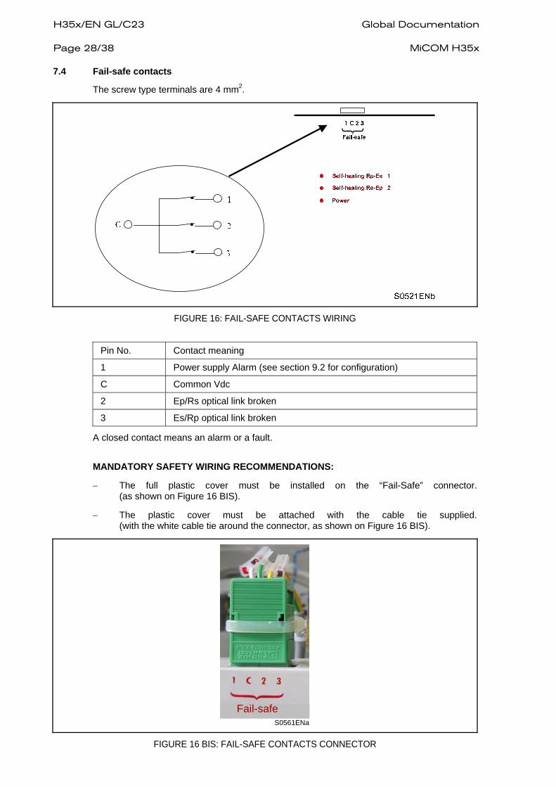
H35x/EN GL/C23 Global Documentation Page 28/38 MiCOM H35x 7.4 Fail-safe contacts
The screw type terminals are 4 mm2.
FIGURE 16: FAIL-SAFE CONTACTS WIRING
Pin No. Contact meaning
1 Power supply Alarm (see section 9.2 for configuration)
C Common Vdc
2 Ep/Rs optical link broken
3 Es/Rp optical link broken
A closed contact means an alarm or a fault.
MANDATORY SAFETY WIRING RECOMMENDATIONS:
− The full plastic cover must be installed on the “Fail-Safe” connector. (as shown on Figure 16 BIS).
− The plastic cover must be attached with the cable tie supplied. (with the white cable tie around the connector, as shown on Figure 16 BIS).
Fail-safeS0561ENa
FIGURE 16 BIS: FAIL-SAFE CONTACTS CONNECTOR

Global Documentation H35x/EN GL/C23 MiCOM H35x Page 29/38 7.5 Ethernet Connection
The Ethernet-based communication available in the MiCOM H35x uses either optical fiber media (ST/SC/LC connector) or 4 twisted pair cable.
If the equipment is located at a long distance (>100 m for RJ45) from the communication equipment or multiplexer, or if the cables run through a noisy area, then optical communication should be used to interconnect the IEDs and the communication equipment.
7.5.1 Ethernet cable type
Only the cable insulated category 5 (FTP: Foil Twisted Pair) or insulated (STP – Shielded Twisted Pair) with RJ45 connectors must be used.
FIGURE 17: RJ45 CONNECTOR
The standard is:
1 = white / orange 2 = orange 3 = white / green 4 = blue (not used) 5 = white / blue (not used) 6 = green 7 = white / brown (not used) 8 = brown (not used)
Looking at the RJ45 connector head on, flat side on bottom and side tab on top, then pin 1 is on the left and pin 8 on the right.
The MiCOM H35x supports star or tree network topology.
The maximum authorized cable length for 10/100BaseTx without using a repeater is 100 meters.
7.5.2 Ethernet optical fiber
The optical fiber cables are connected to the corresponding optical fiber elements.
The H352-V2 P/N 2071684 A01 (multimode fiber) has a type ST connector.
FIGURE 18: ETHERNET OPTICAL FIBER – ST

H35x/EN GL/C23 Global Documentation Page 30/38 MiCOM H35x
The H354-V2 P/N 2071684 A02 (single mode fiber) has a type SC connector.
FIGURE 19: ETHERNET OPTICAL FIBER – SC
The H356-V2 P/N 2071767 A03 (multimode fiber) has a type LC connector.
The H358-V2 P/N 2071767 A04 (single mode fiber) has a type LC connector.
FIGURE 19 BIS: ETHERNET OPTICAL FIBER – LC

Global Documentation H35x/EN GL/C23 MiCOM H35x Page 31/38
8. SETTINGS 8.1 Dip switch description
8 - Power Supply Alarm
1 to 7 - Repeater Address
ON = 0
OFF = 1
S0522ENb
FIGURE 20: DIP SWITCHES
Name Function
Repeater address Define the repeater address on the ring
Power supply alarm Generate alarm if there is no redundant power supply
8.2 Address of the repeater
Each repeater in the ring has a specific address. Each address must be unique and included between 1 and 127.
8.2.1 Configuring the address
The address is equal to the sum of the « OFF bits ».
At the beginning address = 0
If 1 = OFF address = address + 1 If 1 = ON address = address + 0 If 2 = OFF address = address + 2 If 2 = ON address = address + 0 If 3 = OFF address = address + 4 If 3 = ON address = address + 0 If 4 = OFF address = address + 8 If 4 = ON address = address + 0 If 5 = OFF address = address + 16 If 5 = ON address = address + 0 If 6 = OFF address = address + 32 If 6 = ON address = address + 0 If 7 = OFF address = address + 64 If 7 = ON address = address + 0
8.2.2 Example: defining address “10”
J7-1 = ON address = address + 0 J7-2 = OFF address = address + 2 J7-3 = ON address = address + 0 J7-4 = OFF address = address + 8 J7-5 = ON address = address + 0 J7-6 = ON address = address + 0 J7-7 = ON address = address + 0
Address = 10

H35x/EN GL/C23 Global Documentation Page 32/38 MiCOM H35x
FIGURE 21: DIP SWITCHES EXAMPLE
8.3 IP Address of the repeater
The repeater IP address is established in the following way:
Default 254
Repeater numberIP Network Base
S0524ENa
FIGURE 22: IP ADDRESS
There are two tools to configure the IP address, the Schneider Electric_Switch_manager Software or the Schneider Electric_Switch_Ip_Repeater Software.
Note: It is important to note that the Schneider Electric_Switch_manager Software forces the third IP byte field to take the value “254”.
8.4 Power supply alarm
The power supply alarm DIP switch position indicates the role of the Fail contact output:
When positioned to “ON”, “Fail-safe” contact 1 indicates the redundant power supply status.
When positioned to “OFF”, “Fail-safe” contact 1 is unused.
8.5 Label
A rectangular label on top of MiCOM H35x behind Auxiliary Power input J1 J2, gives two major indications:
• Type: H35C2 : Code C for nominal power supply (110 - 220 VDC or VAC) Code B for nominal power supply (24 - 48 VDC or VAC)
• Multimode or Single mode optical fiber supported.
FIGURE 23: MiCOM H35x LABEL

Global Documentation H35x/EN GL/C23 MiCOM H35x Page 33/38
9. MAINTENANCE 9.1 Scope
This chapter describes the maintenance procedure for the MiCOM H3xx.
9.2 Recommendation before maintenance operations
BEFORE CARRYING OUT ANY WORK ON THE EQUIPMENT, THE USER SHOULD BE FAMILIAR WITH THE CONTENTS OF THE SAFETY AND TECHNICAL DATA CHAPTERS (SCHNEIDER ELECTRIC SAFETY GUIDE: SFTY/4L M/C11 OR LATER ISSUE) AND THE RATINGS ON THE EQUIPMENT'S RATING LABEL.
READING THE “SAFETY AND HANDLING” CHAPTER OF THIS DOCUMENT IS MANDATORY BEFORE ANY MAINTENANCE OPERATION.
− All power supply connectors must be disconnected from the device prior to any
maintenance operation.
− When the MiCOM H3xx device is connected to dual external electrical sources, both power supply connectors (main and redundant) should be disconnected prior to any maintenance operation.
FIGURE 24: POWER SUPPLY CONNECTOR
9.3 Maintenance period
Schneider Electric products should be monitored periodically after their installation. Deterioration may occur over time. Because of the electrical and heavy-interference environment, the MiCOM Hxxx should be checked at regular intervals to confirm that it is operating correctly.
The Schneider Electric MiCOM Hxxx has been designed for a life cycle of over 15 years.
MiCOM H3xx is self-supervising and therefore requires less maintenance than previous products. Most problems will lead to an alarm so that fast and appropriate action can be taken. However, some periodic checks should be done to ensure that the external wiring is in proper condition.
If the customer’s organization has a Preventive Maintenance Policy, then the recommended product checks should be included in the regular program.

H35x/EN GL/C23 Global Documentation Page 34/38 MiCOM H35x 9.4 Diagnosis facilities
When a maintenance action is planned, the operator should prepare, act and report.
The minimum preparation is to obtain the commissioning Record Sheet of installed device in order to check the product configuration and its history. The user should also apply personal experience in addition to this manual.
On a first level, the product provides several methods to identify the context of the fault. The main ones are:
• Power LEDs
• Fail-Safe alarm indication
The LEDs and fail-safe indications are described in the chapter Human Machine Interface.
9.5 Method of repair
IN CASE OF DEVICE FAILURE, THE PREFERRED METHOD IS TO REPLACE THE COMPLETE MiCOM H3XX, AS THIS ENSURES THAT THE INTERNAL CIRCUITRY IS PROTECTED AGAINST ELECTROSTATIC DISCHARGE AND PHYSICAL DAMAGE AT ALL TIMES.
9.5.1 Replacing the MiCOM H3xx
The case and connectors have been designed for ease of use, so removing the MiCOM H3xx is very simple.
9.5.1.1 Uninstalling the MiCOM H3xx
Before any disconnection, check that the labels correctly define the connectors and match the description you have.
Otherwise, note the dip-switch positions in order to prepare the new MiCOM H3xx installation.
1. Disconnect both power supply connectors (when wired):
2. Disconnect the MiCOM H3xx Fail-Safe Alarm Connector:
3. Disconnect the Ethernet RJ45 connectors
4. Disconnect the Ethernet optical connectors
5. Disconnect the protective earth connection
6. Withdraw the MiCOM H3xx from the DIN rail carefully, paying attention to its weight.
9.5.1.2 Installing a fresh MiCOM H3xx
To reinstall the repaired or the new MiCOM H3xx:
− Set the new MiCOM H3xx IP address (dip switches)
− Follow the above procedure in reverse.

Global Documentation H35x/EN GL/C23 MiCOM H35x Page 35/38
10. APPLICATIONS 10.1 Fiber Optic budget calculations
Optical power is expressed in Watts. However, the common unit of power measurement is the dBm, defined by the following equation: Power (dBm) = 10 log Power (mW) / 1 mW.
The fiber optic budget is the difference between the power emitted into the fiber and the sensitivity (minimum amount of power required) of the receiver connected through the fiber optic cable.
Link Power Budget = Transmitter Power (dBm) - Receiver Sensitivity (dBm)
FIGURE 25: FIBER BUDGET
Example:
The following example shows the calculation of the maximum range for various types of fiber.
FIGURE 26: FIBER BUDGET EXAMPLE
Fiber type Multimode Single mode
62.5/125 micron 9/125 micron
Power coupled into fiber -19 dBm -15 dBm
Sensitivity -31 dBm -34 dBm
Link budget 12 dB 19 dB

H35x/EN GL/C23 Global Documentation Page 36/38 MiCOM H35x 10.1.1 Example 1: between repeaters
Link budget 12 dB 19 dB
Connector loss (2) 0.8 dB 0.8 dB
Safety Margin 4 dB 4 dB
Allowed link attenuation 6.4 dB 13.4 dB
Typical cable attenuation 1 dB/km 0.4 dB/km
Maximum range 6.4 km 33 km 10.1.2 Example 2: between repeaters with patch panel
Link budget 12 dB 19 dB
Connector loss (6) 0.8 dB 0.8 dB
Patch loss (2) 2 dB 1 dB
Safety Margin 4 dB 4 dB
Allowed link attenuation -0.8 dB 8.2 dB
Typical cable attenuation 1 dB/km 0.4 dB/km
Maximum range 0 20 km
The values given above are only approximate ones. Always use cable and connector losses as specified by the manufacturer.

Global Documentation H35x/EN GL/C23 MiCOM H35x Page 37/38
11. GLOSSARY
100Base Fx The fiber optic ports are full/half duplex at 100 Mbps only.
10Base Tx and 100Base TX
The copper ports are full/half duplex and auto-sense the transmission speed. They will auto-negotiate with the connected device to determine the optimal speed. When the connected device is only capable of transmitting at 10 Mbps, the MiCOM H35x follows the 10 Mbps.
Cat. 5 Category 5 unshielded twisted pair (UTP) cabling. An Ethernet network operating at 10 Mbits/second (10BASE-T) will often tolerate low quality cables, but at 100 Mbits/second (10BASE-Tx) the cable must be rated as Category 5, or Cat 5 or Cat V, by the Electronic Industry Association (EIA). This rating is printed on the cable jacket. Cat 5 cable contains eight conductors, arranged in four twisted pairs, and terminated with an RJ45 type connector. In addition, there are restrictions on maximum cable length for both 10 and 100 Mbits/second networks.
Fast Ethernet An Ethernet system that is designed to operate at 100 Mbps.
Half-duplex A system that allows packets to be transmitted and received, but not at the same time. Contrast with full-duplex.
MAC address The Media Access Control address is a unique 48-bit hardware address assigned to every network interface card. Usually written in the form 01:23:45:67:89:ab.
MIB See “Management Information Base” in section 4.6.5.1.
PHY The OSI Physical Layer: The physical layer provides for transmission of cells over a physical medium.
Power management If there is no cable on a port, most of the circuitry for that port is disabled to save power.
RMON Short for remote monitoring, a network management protocol that allows network information to be gathered at a single workstation. Whereas SNMP gathers network data from a single type of Management Information Base (MIB), RMON 1 defines nine additional MIBs that provide a much richer set of data about network usage. For RMON to work, network devices, such as hubs and switches, must be designed to support it. The newest version of RMON, RMON 2, provides data about traffic at the network layer in addition to the physical layer. This allows administrators to analyze traffic by protocol.
Simple Network Management Protocol
SNMP is the protocol governing network management and the monitoring of network devices and their functions.
H35x/EN GL/C23 Global Documentation Page 38/38 MiCOM H35x
BLANK PAGE


Customer Care Centre
http://www.schneider-electric.com/CCC
© 2
011
Sch
neid
er E
lect
ric. A
ll rig
hts
rese
rved
.
Schneider Electric 35 rue Joseph Monier 92506 Rueil-Malmaison FRANCE
Phone: +33 (0) 1 41 29 70 00 Fax: +33 (0) 1 41 29 71 00 www.schneider-electric.com Publishing: Schneider ElectricPublication: H35x/EN GL/C23 05/2011