Michael Gentile, Site Acquisition Centerline ...
48
Michael Gentile, Site Acquisition c/o New Cingular Wireless, PCS LLC (AT&T) Centerline Communications, LLC 95 Ryan Drive, Suite 1 Raynham, MA 02767 Mobile: (508) 844-9813 [email protected] January 22, 2016 Melanie A. Bachman Acting Executive Director Connecticut Siting Council 10 Franklin Square New Britain, CT 06051 RE: Notice of Exempt Modification // Site Number: CT1066 213 High Street, Portland, CT 06480 (Name: Portland) N 41.580833333333// W -72.623888888889 Dear Ms. Bachman: New Cingular Wireless, PCS, LLC (“AT&T”) currently maintains nine (9) antennas at the 77-foot level of the existing 80-foot self-support lattice tower at 213 High Street, Portland, CT 06480 (Please note, this address is also known as 97 High Street in the Portland, CT Assessor Database). The tower is owned by New Cingular Wireless PCS, LLC (“AT&T”). The property is also owned by AT&T. AT&T now intends to replace three (3) of its existing antennas with three (3) new LTE (700/1900 band) antennas for its LTE upgrade, as well as relocate three (3) others. These antennas would be installed at the 77-foot level of the tower. AT&T also intends to install three (3) remote radio units and three (3) remote radio unit modules as well as one (1) DC Surge Suppressor. The current proposal involves an antenna swap only (three for three); no antennas will be added. Prior conditions do not pertain. Please accept this letter as notification pursuant to Regulations of Connecticut State Agencies § 16-50j-73, for construction that constitutes an exempt modification pursuant to R.C.S.A. § 16- 50j-72(b)(2). In accordance with R.C.S.A. § 16-50j-73, a copy of this letter is being sent to Susan Bransfield, First Selectwoman for the Town of Portland, as well as the property owner and tower owner, which are both AT&T in this case. The planned modifications to the facility fall squarely within those activities explicitly provided for in R.C.S.A. § 16-50j-72(b)(2). Attached to accommodate this filing are construction drawings dated January 21, 2016 by ComEx Consultants, a structural analysis dated December 17, 2015 by B&T Group and an Emissions Analysis Report dated January 10, 2016 by EBI Consulting.
Transcript of Michael Gentile, Site Acquisition Centerline ...

Michael Gentile, Site Acquisition
c/o New Cingular Wireless, PCS LLC (AT&T)
Centerline Communications, LLC
95 Ryan Drive, Suite 1
Raynham, MA 02767
Mobile: (508) 844-9813
January 22, 2016
Melanie A. Bachman
Acting Executive Director
Connecticut Siting Council
10 Franklin Square
New Britain, CT 06051
RE: Notice of Exempt Modification // Site Number: CT1066
213 High Street, Portland, CT 06480 (Name: Portland)
N 41.580833333333// W -72.623888888889
Dear Ms. Bachman:
New Cingular Wireless, PCS, LLC (“AT&T”) currently maintains nine (9) antennas at the
77-foot level of the existing 80-foot self-support lattice tower at 213 High Street, Portland, CT
06480 (Please note, this address is also known as 97 High Street in the Portland, CT Assessor
Database). The tower is owned by New Cingular Wireless PCS, LLC (“AT&T”). The property is
also owned by AT&T. AT&T now intends to replace three (3) of its existing antennas with three
(3) new LTE (700/1900 band) antennas for its LTE upgrade, as well as relocate three (3) others.
These antennas would be installed at the 77-foot level of the tower. AT&T also intends to install
three (3) remote radio units and three (3) remote radio unit modules as well as one (1) DC Surge
Suppressor.
The current proposal involves an antenna swap only (three for three); no antennas will be added.
Prior conditions do not pertain.
Please accept this letter as notification pursuant to Regulations of Connecticut State Agencies §
16-50j-73, for construction that constitutes an exempt modification pursuant to R.C.S.A. § 16-
50j-72(b)(2). In accordance with R.C.S.A. § 16-50j-73, a copy of this letter is being sent to Susan
Bransfield, First Selectwoman for the Town of Portland, as well as the property owner and tower
owner, which are both AT&T in this case.
The planned modifications to the facility fall squarely within those activities explicitly provided
for in R.C.S.A. § 16-50j-72(b)(2).
Attached to accommodate this filing are construction drawings dated January 21, 2016 by
ComEx Consultants, a structural analysis dated December 17, 2015 by B&T Group and an
Emissions Analysis Report dated January 10, 2016 by EBI Consulting.

1. The proposed modifications will not result in an increase in the height of the existing structure.
2. The proposed modifications will not require the extension of the site boundary.
3. The proposed modifications will not increase noise levels at the facility by six decibels or
more, or to levels that exceed state and local criteria.
4. The operation of the replacement antennas will not increase radio frequency emissions at the
facility to a level at or above the Federal Communications Commission safety standard.
5. The proposed modifications will not cause a change or alteration in the physical or
environmental characteristics of the site.
6. The existing structure and its foundation can support the proposed loading as shown in the
attached structural analysis by B&T Group, dated December 17, 2015.
For the foregoing reasons, AT&T respectfully submits that the proposed modifications to the
above referenced telecommunications facility constitute an exempt modification under R.C.S.A.
§ 16-50j-72(b)(2).
Sincerely,
_____________________________________
Michael Gentile, Site Acquisition
c/o New Cingular Wireless, PCS LLC (AT&T)
Centerline Communications, LLC
95 Ryan Drive, Suite 1
Raynham, MA 02767
Mobile: (508) 844-9813
Attachments
cc: Susan Bransfield, Town of Portland - as elected official
New Cingular Wireless PCS, LLC - as tower owner
New Cingular Wireless PCS, LLC - as property owner

EBI Consulting environmental | engineering | due diligence
21 B Street . Burlington, MA 01803
. Tel: (781) 273.2500
. Fax: (781) 273.3311
RADIO FREQUENCY EMISSIONS ANALYSIS REPORTEVALUATION OF HUMAN EXPOSURE POTENTIAL
TO NON-IONIZING EMISSIONS
AT&T Existing Facility
Site ID: CT1066
Portland213 High Street
Portland, CT 06480
January 10, 2016
EBI Project Number: 6216000143
Site Compliance Summary
Compliance Status: COMPLIANT
Site total MPE% of
FCC general public
allowable limit: 11.58 %

EBI Consulting environmental | engineering | due diligence
21 B Street . Burlington, MA 01803
. Tel: (781) 273.2500
. Fax: (781) 273.3311
January 10, 2016
AT&T Mobility – New England
Attn: Cameron Syme, RF Manager
550 Cochituate Road
Suite 550 – 13&14
Framingham, MA 06040
Emissions Analysis for Site: CT1066 – Portland
EBI Consulting was directed to analyze the proposed AT&T facility located at 213 High Street,
Portland, CT, for the purpose of determining whether the emissions from the Proposed AT&T Antenna
Installation located on this property are within specified federal limits.
All information used in this report was analyzed as a percentage of current Maximum Permissible
Exposure (% MPE) as listed in the FCC OET Bulletin 65 Edition 97-01and ANSI/IEEE Std C95.1. The
FCC regulates Maximum Permissible Exposure in units of microwatts per square centimeter ( W/cm2).
The number of W/cm2 calculated at each sample point is called the power density. The exposure limit
for power density varies depending upon the frequencies being utilized. Wireless Carriers and Paging
Services use different frequency bands each with different exposure limits, therefore it is necessary to
report results and limits in terms of percent MPE rather than power density.
All results were compared to the FCC (Federal Communications Commission) radio frequency exposure
rules, 47 CFR 1.1307(b)(1) – (b)(3), to determine compliance with the Maximum Permissible Exposure
(MPE) limits for General Population/Uncontrolled environments as defined below.
General population/uncontrolled exposure limits apply to situations in which the general public may be
exposed or in which persons who are exposed as a consequence of their employment may not be made
fully aware of the potential for exposure or cannot exercise control over their exposure. Therefore,
members of the general public would always be considered under this category when exposure is not
employment related, for example, in the case of a telecommunications tower that exposes persons in a
nearby residential area.
Public exposure to radio frequencies is regulated and enforced in units of microwatts per square 2). The general population exposure limits for the 700 and 850 MHz Bands are
approximately 4 2 and 5 2 respectively. The general population exposure limit for the
1900 MHz (PCS), 2100 MHz (AWS) and 2300 MHz (WCS) bands 2. Because each carrier
will be using different frequency bands, and each frequency band has different exposure limits, it is
necessary to report percent of MPE rather than power density.

EBI Consulting environmental | engineering | due diligence
21 B Street . Burlington, MA 01803
. Tel: (781) 273.2500
. Fax: (781) 273.3311
Occupational/controlled exposure limits apply to situations in which persons are exposed as a
consequence of their employment and in which those persons who are exposed have been made fully
aware of the potential for exposure and can exercise control over their exposure. Occupational/controlled
exposure limits also apply where exposure is of a transient nature as a result of incidental passage through
a location where exposure levels may be above general population/uncontrolled limits (see below), as
long as the exposed person has been made fully aware of the potential for exposure and can exercise
control over his or her exposure by leaving the area or by some other appropriate means.
Additional details can be found in FCC OET 65.
CALCULATIONS
Calculations were done for the proposed AT&T Wireless antenna facility located at 213 High Street,
Portland, CT, using the equipment information listed below. All calculations were performed per the
specifications under FCC OET 65. Since AT&T is proposing highly focused directional panel antennas,
which project most of the emitted energy out toward the horizon, all calculations were performed
assuming a lobe representing the maximum gain of the antenna per the antenna manufactures supplied
specifications, minus 10 dB, was focused at the base of the tower. For this report the sample point is the
top of a 6 foot person standing at the base of the tower.
For all calculations, all equipment was calculated using the following assumptions:
1) 2 UMTS channels (850 MHz) were considered for each sector of the proposed installation.
These Channels have a transmit power of 30 Watts per Channel.
2) 2 UMTS channels (PCS Band – 1900 MHz) were considered for each sector of the proposed
installation. These Channels have a transmit power of 30 Watts per Channel.
3) 2 LTE channels (700 MHz) were considered for each sector of the proposed installation.
These Channels have a transmit power of 60 Watts per Channel.
4) 2 LTE channels (PCS Band – 1900 MHz) were considered for each sector of the proposed
installation. These Channels have a transmit power of 60 Watts per Channel.
5) 2 GSM channels (850 MHz) were considered for each sector of the proposed installation.
These Channels have a transmit power of 30 Watts per Channel.
6) 2 GSM channels (PCS Band – 1900 MHz) were considered for each sector of the proposed
installation. These Channels have a transmit power of 30 Watts per Channel.

EBI Consulting environmental | engineering | due diligence
21 B Street . Burlington, MA 01803
. Tel: (781) 273.2500
. Fax: (781) 273.3311
7) All radios at the proposed installation were considered to be running at full power and were
uncombined in their RF transmissions paths per carrier prescribed configuration. Per FCC
OET Bulletin No. 65 - Edition 97-01 recommendations to achieve the maximum anticipated
value at each sample point, all power levels emitting from the proposed antenna installation
are increased by a factor of 2.56 to account for possible in-phase reflections from the
surrounding environment. This is rarely the case, and if so, is never continuous.
8) For the following calculations the sample point was the top of a six foot person standing at
the base of the tower. The maximum gain of the antenna per the antenna manufactures
supplied specifications minus 10 dB was used in this direction. This value is a very
conservative estimate as gain reductions for these particular antennas are typically much
higher in this direction.
9) The antennas used in this modeling are the Kathrein 800-10121, CCI HPA-65R-BUU-H6
and the KMW AM-X-CD-16-65-00T-RET for transmission in the 700 MHz, 850 MHz
and1900 MHz (PCS) frequency bands. This is based on feedback from the carrier with
regards to anticipated antenna selection. Maximum gain values for all antennas are listed in
the Inventory and Power Data table below. The maximum gain of the antenna per the antenna
manufactures supplied specifications, minus 10 dB, was used for all calculations. This value
is a very conservative estimate as gain reductions for these particular antennas are typically
much higher in this direction.
10) The antenna mounting height centerline of the proposed antennas is 75 feet above ground
level (AGL).
11) Emissions values for additional carriers were taken from the Connecticut Siting Council
active database. Values in this database are provided by the individual carriers themselves.
All calculations were done with respect to uncontrolled / general public threshold limits.

EBI Consulting environmental | engineering | due diligence
21 B Street . Burlington, MA 01803
. Tel: (781) 273.2500
. Fax: (781) 273.3311
AT&T Site Inventory and Power Data
Sector: A Sector: B Sector: C
Antenna #: 1 Antenna #: 1 Antenna #: 1
Make / Model: Kathrein 800-10121 Make / Model: Kathrein 800-10121 Make / Model: Kathrein 800-10121
Gain: 11.45 / 14.45 dBd Gain: 11.45 / 14.45 dBd Gain: 11.45 / 14.45 dBd
Height (AGL): 75 feet Height (AGL): 75 feet Height (AGL): 75 feet
Frequency Bands850 MHz /
1900 MHz (PCS)Frequency Bands
850 MHz /
1900 MHz (PCS)Frequency Bands
850 MHz /
1900 MHz (PCS)
Channel Count 4 Channel Count 4 Channel Count 4
Total TX Power(W): 120 Total TX Power(W): 120 Total TX Power(W): 120
ERP (W): 2,509.49 ERP (W): 2,509.49 ERP (W): 2,509.49
Antenna A1 MPE% 2.38 Antenna B1 MPE% Kathrein 800-10121 Antenna C1 MPE% Kathrein 800-10121
Antenna #: 2 Antenna #: 2 Antenna #: 2
Make / Model:CCI
HPA-65R-BUU-H6Make / Model:
CCI
HPA-65R-BUU-H6Make / Model:
CCI
HPA-65R-BUU-H6
Gain: 11.95 / 14.75 dBd Gain: 11.95 / 14.75 dBd Gain: 11.95 / 14.75 dBd
Height (AGL): 75 feet Height (AGL): 75 feet Height (AGL): 75 feet
Frequency Bands700 MHz /
1900 MHz (PCS)Frequency Bands
700 MHz /
1900 MHz (PCS)Frequency Bands
700 MHz /
1900 MHz (PCS)
Channel Count 4 Channel Count 4 Channel Count 4
Total TX Power(W): 240 Total TX Power(W): 240 Total TX Power(W): 240
ERP (W): 5,462.56 ERP (W): 5,462.56 ERP (W): 5,462.56
Antenna A2 MPE% 5.75 Antenna B2 MPE% 5.75 Antenna C2 MPE% 5.75
Antenna #: 3 Antenna #: 3 Antenna #: 3
Make / Model:
KMW
AM-X-CD-16-65-
00T-RET
Make / Model:
KMW
AM-X-CD-16-65-
00T-RET
Make / Model:
KMW
AM-X-CD-16-65-
00T-RET
Gain: 13.85 / 15.25 dBd Gain: 13.85 / 15.25 dBd Gain: 13.85 / 15.25 dBd
Height (AGL): 75 feet Height (AGL): 75 feet Height (AGL): 75 feet
Frequency Bands850 MHz /
1900 MHz (PCS)Frequency Bands
850 MHz /
1900 MHz (PCS)Frequency Bands
850 MHz /
1900 MHz (PCS)
Channel Count 4 Channel Count 4 Channel Count 4
Total TX Power(W): 120 Total TX Power(W): 120 Total TX Power(W): 120
ERP (W): 3,465.76 ERP (W): 3,465.76 ERP (W): 3,465.76
Antenna A3 MPE% 3.46 Antenna B3 MPE% 3.46 Antenna C3 MPE% 3.46
Site Composite MPE%Carrier MPE%
AT&T – Max per sector 11.58 %
No Additional Carriers NA
Site Total MPE %: 11.58 %
AT&T Sector 1 Total: 2.28 %
AT&T Sector 2 Total: 2.64 %
AT&T Sector 3 Total: 2.10 %
Site Total: 11.58 %
AT&T _ Per Sector # ChannelsWatts ERP
(Per Channel)
Height
(feet)
Total Power
Density
( W/cm2)
Frequency
(MHz)
Allowable
MPE
( W/cm2)
Calculated %
MPE
AT&T 850 MHz UMTS 2 418.91 75 6.33 850 567 1.12 %
AT&T 1900 MHz (PCS) UMTS 2 835.84 75 12.62 1900 1000 1.26 %
AT&T 850 MHz LTE 2 940.05 75 14.20 700 467 3.04 %
AT&T 1900 MHz (PCS) LTE 2 1791.23 75 27.05 1900 1000 2.71 %
AT&T 700 MHz GSM 2 727.98 75 10.99 850 567 1.94 %
AT&T 1900 MHz (PCS) GSM 2 1004.90 75 15.18 1900 1000 1.52 %
Total: 11.58 %
EBI Consulting environmental | engineering | due diligence
21 B Street . Burlington, MA 01803
. Tel: (781) 273.2500
. Fax: (781) 273.3311
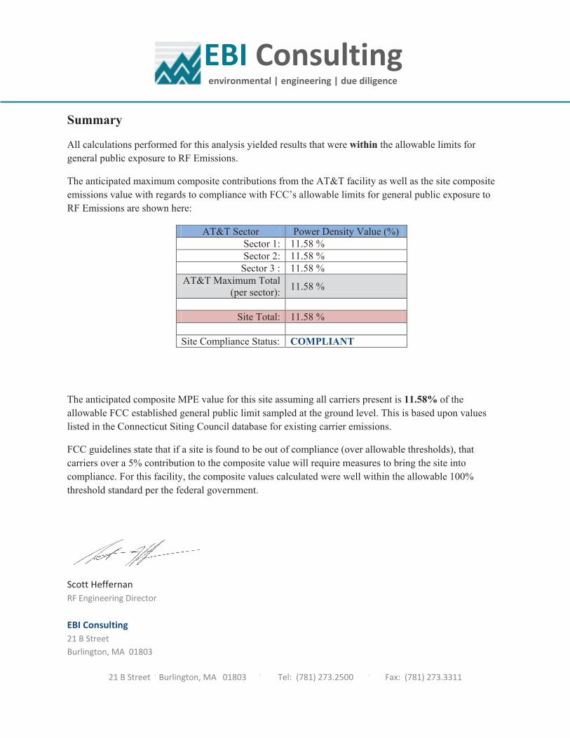
Summary
All calculations performed for this analysis yielded results that were within the allowable limits for
general public exposure to RF Emissions.
The anticipated maximum composite contributions from the AT&T facility as well as the site composite
emissions value with regards to compliance with FCC’s allowable limits for general public exposure to
RF Emissions are shown here:
AT&T Sector Power Density Value (%)
Sector 1: 11.58 %
Sector 2: 11.58 %
Sector 3 : 11.58 %
AT&T Maximum Total
(per sector):11.58 %
Site Total: 11.58 %
Site Compliance Status: COMPLIANT
The anticipated composite MPE value for this site assuming all carriers present is 11.58% of the
allowable FCC established general public limit sampled at the ground level. This is based upon values
listed in the Connecticut Siting Council database for existing carrier emissions.
FCC guidelines state that if a site is found to be out of compliance (over allowable thresholds), that
carriers over a 5% contribution to the composite value will require measures to bring the site into
compliance. For this facility, the composite values calculated were well within the allowable 100%
threshold standard per the federal government.
Scott Heffernan
RF Engineering Director
EBI Consulting
21 B Street
Burlington, MA 01803


80 Ft Self-Support Tower Structural Analysis
Portland, 59359
ANALYSIS RESULTS:
Table 1 - Section Capacity (Summary)
Table 2 - Tower Component Stresses vs. Capacity
Notes:
1)
Recommendations:
N/A
The base foundation could not be analyzed as part of this analysis, as foundation and geotechnical information was not available. It is
assumed that the foundation was designed with capacities similar to the tower itself and is therefore considered sufficient for the purposes
of this analysis.
1 Base Foundation
% Capacity
Base -- --
Component
December 17, 2015
B+T Project No: 103654.001.01
Page 2
Pass / Fail
Pass / Fail
15.9
Pass
Diagonal (T5) 84.9 Pass
Elevation (ft)Notes
Component (Tower Section) % Capacity
6.6 Pass
Secondary Horizontal (T5) 65.3 Pass
Horizontal (T1)
Leg (T5) 71.4
Bolt Checks 36.8 Pass
Top Girt (T4) Pass
-
84.9%Structure Rating (max from all components) =
Base 36.7 PassAnchor Rods

80 Ft Self-Support Tower Structural Analysis
Portland, 59359
ANALYSIS PROCEDURE:
Table 3 - Documents Provided
ANALYSIS METHOD:
ASSUMPTIONS:
1. Tower and structures were built in accordance with the manufacturer's specifications.
2. The tower and structures have been maintained in accordance with the manufacturer's specifications.
3. The configuration of antennas, transmission cables, mounts and other appurtenances are as specified in
Appendix A of this report.
4. Mount areas and weights are assumed based on photographs provided.
5. Refer to the base level drawing for transmission line distribution.
6.
7.
Siterra
6/14/2012 On File
tnxTower, a commercially available analysis software package, was used to create a three-dimensional model of the
tower and calculate member stresses for various loading cases. Selected output from the analysis is included in
Appendix B.
LoadingEquipment Modification Form; LTE MOD ADD_11-
20-2015
B+T Project 84420.001; MOD LTE W3
B+T Project 84420.001; MOD LTE W3 6/14/2012
December 17, 2015
B+T Project No: 103654.001.01
Page 3
N/A N/A
N/AN/A
Source
On File
Foundation Information Information Not Available
11/24/2015
On File
Geotech Report Information Not Available
4/26/2012
All proposed loading was taken from the Equipment Modification Form.
If any of these assumptions have been made in error, B+T Group should be notified to determine the effect on the
structural integrity of the tower.
Previous Structural Analysis
Date
All other existing/reserved loading was taken from the previous analysis unless otherwise noted.
Document Description
Tower Data BTE Project 15085

APPENDIX A
TOWER ANALYSIS LOADING

80 F
t S
elf-S
upport
Tow
er
Str
uctu
ral A
naly
sis
Port
land,
59359
TO
WE
R A
NA
LY
SIS
LO
AD
ING
:
Exis
tin
g /
Reserv
ed
Lo
ad
ing
An
ten
na
Ow
ne
r
Mount
Heig
ht
(ft)
Ante
nna
CL
(ft)
Qu
an
tity
Manufa
ctu
rer
Mo
de
lQ
ua
nti
tyT
yp
eQ
ua
nti
tyS
ize
(in
)
AT
&T
77.5
77.5
6K
ath
rein
800-1
0121
3R
ing
w/
Secto
red
Fra
me
12
7/8
"
AT
&T
77.5
77.5
3*
KM
WA
MT
-X-C
D16-6
5-0
0T
23/4
"
AT
&T
77.5
77.5
6A
DC
CG
I1900W
850B
P1
1/2
"
AT
&T
77.5
77.5
6C
CI
DT
MA
BP
7819V
G12A
AT
&T
77.5
77.5
3E
ricsso
nR
RU
S-1
1
AT
&T
75.5
75.5
1R
aycap
DC
6-4
8-6
0-1
8-F
Ab
an
do
ned
77.5
--3
7/8
"
Ab
an
do
ned
77.5
--3
1-5
/8"
*Equip
ment
to b
e R
em
oved
Pro
po
sed
Lo
ad
ing
An
ten
na
Ow
ne
r
Mount
Heig
ht
(ft)
Ante
nna
CL
(ft)
Qu
an
tity
Manufa
ctu
rer
Mo
de
lQ
ua
nti
tyT
yp
eQ
ua
nti
tyS
ize
(in
)
AT
&T
77.5
77.5
3C
CI
HP
A-6
5R
-BU
U-H
6
AT
&T
77.5
77.5
3E
ricsso
nR
RU
S-1
2
AT
&T
77.5
77.5
3E
ricsso
nR
RU
S A
2 M
od
ule
Note
: S
ee B
ase L
evel D
raw
ing F
or
Tra
nsm
issio
n L
ine D
istr
ibution
Fu
ture
Lo
ad
ing
An
ten
na
Ow
ne
r
Mount
Heig
ht
(ft)
Ante
nna
CL
(ft)
Qu
an
tity
Manufa
ctu
rer
Mo
de
lQ
ua
nti
tyT
yp
eQ
ua
nti
tyS
ize
(in
)
Decem
ber
17,
2015
B+
T P
roje
ct
No:
103654.0
01.0
1
An
ten
na
Mo
un
tT
ran
smis
sio
n L
ine
An
ten
na
Mo
un
tT
ran
smis
sio
n L
ine
An
ten
na
Mo
un
tT
ran
smis
sio
n L
ine

APPENDIX B
CALCULATIONS

B+T Group 1717 S. Boulder, Suite 300
Tulsa, OK 74119 Phone: (918) 587-4630
FAX: (918) 587-4630
Job:103654.001.01 - Portland, CT (USID# 59359)
Project: LTE MOD ADD_11-20-2015Client: Centerline Communications Drawn by: Shashank.S.Rao App'd:
Code: TIA/EIA-222-F Date: 12/17/15 Scale: NTS Path:
C:\Users\Sumanth\Desktop\December 2015\17-12-2015\RUSH_Compile_103654_CT1066_10035005_Portland--Shahsank--Pangal\Tnx_001_01\103654_001_01_Portland_CT.eri
Dwg No. E-1
80.0 ft
66.0 ft
54.0 ft
24.0 ft
14.8 ft
0.0 ft
REACTIONS - 85 mph WIND
TORQUE 15 kip-ft
19 K
SHEAR
920 kip-ft
MOMENT
15 K
AXIAL
38 mph WIND - 0.750 in ICE
TORQUE 4 kip-ft
5 K
SHEAR
265 kip-ft
MOMENT
28 K
AXIAL
SHEAR: 7 K
UPLIFT: -46 K
SHEAR: 8 K
DOWN: 53 K
MAX. CORNER REACTIONS AT BASE:
S
ectio
nT
1T
2T
3T
4T
5
L
eg
sL
4x4
x3
/8L
5x5
x7
/16
L
eg
Gra
de
A3
6
D
iag
on
als
L2
1/2
x2
x3
/16
L3
x3
x3
/16
D
iag
on
al G
rad
eA
36
T
op
Gir
tsL
2x2
x3
/16
L3
x3
x3
/16
L2
1/2
x2
1/2
x3
/16
L2
1/2
x2
x3
/16
N.A
.
H
ori
zo
nta
lsL
3 1
/2x3
1/2
x1
/4N
.A.
S
ec.
Ho
rizo
nta
ls2
L4
x4
x1
/4x3
/8N
.A.
L1
1/2
x1
1/2
x1
/8
F
ace
Wid
th (
ft)
5.3
75
6.7
91
67
10
.33
33
11
.42
45
13
.16
67
#
Pa
ne
ls @
(ft
)4
@ 3
.52
@ 6
4 @
7.5
1 @
9.2
51
@ 1
4.6
66
7
W
eig
ht
(K)
1.6
1.0
2.9
1.1
1.5
8.2
Lighting Rod 5/8" x 8' (E) 84(2) 800 10121 (E) 77.5(2) 800 10121 (E) 77.5(2) 800 10121 (E) 77.5(2) CG1900W850BP (E) 77.5(2) CG1900W850BP (E) 77.5(2) CG1900W850BP (E) 77.5(2) DTMABP7819VG12A (E) 77.5(2) DTMABP7819VG12A (E) 77.5(2) DTMABP7819VG12A (E) 77.5RRUS-11 (E) 77.5RRUS-11 (E) 77.5RRUS-11 (E) 77.5HPA-65R-BUU-H6 (P) 77.5HPA-65R-BUU-H6 (P) 77.5HPA-65R-BUU-H6 (P) 77.5RRUS-12 (P) 77.5RRUS-12 (P) 77.5RRUS-12 (P) 77.5RRUS-A2 (P) 77.5RRUS-A2 (P) 77.5RRUS-A2 (P) 77.5Dual Ring Halo (E) 77.5Sector Mount [SM 301-3] (E) 77.5(3) 10' x 2" Mount Pipe (E-Per Photo) 77.5(3) 10' x 2" Mount Pipe (E-Per Photo) 77.5(3) 10' x 2" Mount Pipe (E-Per Photo) 77.5DC6-48-60-18-8F (E) 75.5Dual Ring Halo (E) 75.5Dual Ring Halo (E) 68Cat walk (E) 51DESIGNED APPURTENANCE LOADING
TYPE TYPEELEVATION ELEVATION
Lighting Rod 5/8" x 8' (E) 84
(2) 800 10121 (E) 77.5
(2) 800 10121 (E) 77.5
(2) 800 10121 (E) 77.5
(2) CG1900W850BP (E) 77.5
(2) CG1900W850BP (E) 77.5
(2) CG1900W850BP (E) 77.5
(2) DTMABP7819VG12A (E) 77.5
(2) DTMABP7819VG12A (E) 77.5
(2) DTMABP7819VG12A (E) 77.5
RRUS-11 (E) 77.5
RRUS-11 (E) 77.5
RRUS-11 (E) 77.5
HPA-65R-BUU-H6 (P) 77.5
HPA-65R-BUU-H6 (P) 77.5
HPA-65R-BUU-H6 (P) 77.5
RRUS-12 (P) 77.5
RRUS-12 (P) 77.5
RRUS-12 (P) 77.5
RRUS-A2 (P) 77.5
RRUS-A2 (P) 77.5
RRUS-A2 (P) 77.5
Dual Ring Halo (E) 77.5
Sector Mount [SM 301-3] (E) 77.5
(3) 10' x 2" Mount Pipe (E-Per Photo) 77.5
(3) 10' x 2" Mount Pipe (E-Per Photo) 77.5
(3) 10' x 2" Mount Pipe (E-Per Photo) 77.5
DC6-48-60-18-8F (E) 75.5
Dual Ring Halo (E) 75.5
Dual Ring Halo (E) 68
Cat walk (E) 51
MATERIAL STRENGTHGRADE GRADEFy FyFu Fu
A36 36 ksi 58 ksi
TOWER DESIGN NOTES1. Tower is located in Middlesex County, Connecticut.2. Tower designed for a 85 mph basic wind in accordance with the TIA/EIA-222-F Standard.3. Tower is also designed for a 38 mph basic wind with 0.75 in ice. Ice is considered to increase
in thickness with height.
4. Deflections are based upon a 50 mph wind.5. TOWER RATING: 84.9%

B+T Group 1717 S. Boulder, Suite 300
Tulsa, OK 74119 Phone: (918) 587-4630
FAX: (918) 587-4630
Job:103654.001.01 - Portland, CT (USID# 59359)
Project: LTE MOD ADD_11-20-2015Client: Centerline Communications Drawn by: Shashank.S.Rao App'd:
Code: TIA/EIA-222-F Date: 12/17/15 Scale: NTS Path:
C:\Users\Sumanth\Desktop\December 2015\17-12-2015\RUSH_Compile_103654_CT1066_10035005_Portland--Shahsank--Pangal\Tnx_001_01\103654_001_01_Portland_CT.eri
Dwg No. E-7
Feed Line Plan
Round Flat App In Face App Out Face
A
B
C
D
(15) LDF5-50A(7/8") (12E+3AB)
(2) ASU9330TYP01(3/4") (E)
LDF4P-50A(1/2") (E)
(3) LDF7-50A(1 5/8") (AB)
Feedline Ladder (Af) (E)
3/4" conduit (E)

B+T Group 1717 S. Boulder, Suite 300
Tulsa, OK 74119 Phone: (918) 587-4630
FAX: (918) 587-4630
Job:103654.001.01 - Portland, CT (USID# 59359)
Project: LTE MOD ADD_11-20-2015 Client: Centerline Communications Drawn by: Shashank.S.Rao App'd:
Code: TIA/EIA-222-F Date: 12/17/15 Scale: NTS Path:
C:\Users\Sumanth\Desktop\December 2015\17-12-2015\RUSH_Compile_103654_CT1066_10035005_Portland--Shahsank--Pangal\Tnx_001_01\103654_001_01_Portland_CT.eri
Dwg No. E-7
Feed Line Distribution Chart
0' - 80'Round Flat App In Face App Out Face Truss Leg
Face A
66'
54'
24'
14'9"
0'
80'
Ele
va
tio
n (
ft)
Face B
77'6"77'6"77'6"77'6"77'6"
50'
Face C
77'6"77'6"77'6"77'6"77'6"
50'
(15
) L
DF
5-5
0A
(7/8
") (
12
E+
3A
B)
(2)
AS
U9
33
0T
YP
01
(3/4
") (
E)
LD
F4
P-5
0A
(1/2
") (
E)
(3)
LD
F7
-50
A(1
5/8
") (
AB
)
Fe
ed
line
La
dd
er
(Af)
(E
)
3/4
" co
nd
uit (
E)
Face D
66'
54'
24'
14'9"
0'
80'
77'6"77'6"77'6"77'6"77'6"
50'

B+T Group 1717 S. Boulder, Suite 300
Tulsa, OK 74119 Phone: (918) 587-4630
FAX: (918) 587-4630
Job:103654.001.01 - Portland, CT (USID# 59359)
Project: LTE MOD ADD_11-20-2015Client: Centerline Communications Drawn by: Shashank.S.Rao App'd:
Code: TIA/EIA-222-F Date: 12/17/15 Scale: NTS Path:
C:\Users\Sumanth\Desktop\December 2015\17-12-2015\RUSH_Compile_103654_CT1066_10035005_Portland--Shahsank--Pangal\Tnx_001_01\103654_001_01_Portland_CT.eri
Dwg No. E-2
Base Elev=0'
15' 15'
43'2"
13'2"
6'7" 6'7"
43
'2"
15
'1
5'
13
'2"
6'7
"6
'7"
Plot PlanTotal Area - 0.04 Acres

B+T Group 1717 S. Boulder, Suite 300
Tulsa, OK 74119 Phone: (918) 587-4630
FAX: (918) 587-4630
Job:103654.001.01 - Portland, CT (USID# 59359)
Project: LTE MOD ADD_11-20-2015 Client: Centerline Communications Drawn by: Shashank.S.Rao App'd:
Code: TIA/EIA-222-F Date: 12/17/15 Scale: NTS Path:
C:\Users\Sumanth\Desktop\December 2015\17-12-2015\RUSH_Compile_103654_CT1066_10035005_Portland--Shahsank--Pangal\Tnx_001_01\103654_001_01_Portland_CT.eri
Dwg No. E-3
<- Minimum -0 Maximum ->
<- Minimum -0 Maximum ->
-50
-50
-100
-100
-150
-150
50
50
100
100
150
150
TIA/EIA-222-F - 85 mph/38 mph 0.750 in Ice
Leg Capacity Leg Compression (K)
80' 80'
66' 66'
54' 54'
24' 24'
14'9" 14'9"
0' 0'
Ele
va
tio
n (
ft)

B+T Group 1717 S. Boulder, Suite 300
Tulsa, OK 74119 Phone: (918) 587-4630
FAX: (918) 587-4630
Job:103654.001.01 - Portland, CT (USID# 59359)
Project: LTE MOD ADD_11-20-2015Client: Centerline Communications Drawn by: Shashank.S.Rao App'd:
Code: TIA/EIA-222-F Date: 12/17/15 Scale: NTS Path:
C:\Users\Sumanth\Desktop\December 2015\17-12-2015\RUSH_Compile_103654_CT1066_10035005_Portland--Shahsank--Pangal\Tnx_001_01\103654_001_01_Portland_CT.eri
Dwg No. E-4
0
0
5
5
10
10
15
15
20
20
Global Mast Shear (K)
80'
66'
54'
24'
14'9"
0'
Ele
va
tio
n (
ft)
0
0
500
500
1000
1000
Global Mast Moment (kip-ft)
80'
66'
54'
24'
14'9"
0'
TIA/EIA-222-F - 85 mph/38 mph 0.750 in Ice Maximum Values
Vx Vz Mx Mz

B+T Group 1717 S. Boulder, Suite 300
Tulsa, OK 74119 Phone: (918) 587-4630
FAX: (918) 587-4630
Job:103654.001.01 - Portland, CT (USID# 59359)
Project: LTE MOD ADD_11-20-2015Client: Centerline Communications Drawn by: Shashank.S.Rao App'd:
Code: TIA/EIA-222-F Date: 12/17/15 Scale: NTS Path:
C:\Users\Sumanth\Desktop\December 2015\17-12-2015\RUSH_Compile_103654_CT1066_10035005_Portland--Shahsank--Pangal\Tnx_001_01\103654_001_01_Portland_CT.eri
Dwg No. E-5
TIA/EIA-222-F - Service - 50 mph Maximum Values
0
0
0.5
0.5
1
1
Deflection (in)
80'
66'
54'
24'
14'9"
0'
Ele
va
tio
n (
ft)
0
0
0.05
0.05
0.1
0.1
Tilt (deg)0
0
0.05
0.05
0.1
0.1
Twist (deg)
80'
66'
54'
24'
14'9"
0'

ttnnxxTToowweerrJob
103654.001.01 - Portland, CT (USID# 59359)
Page
1 of 20
B+T Group1717 S. Boulder, Suite 300
Project
LTE MOD ADD_11-20-2015
Date
16:22:39 12/17/15
Tulsa, OK 74119
Phone: (918) 587-4630
FAX: (918) 587-4630
Client
Centerline Communications Designed by
Shashank.S.Rao
Tower Input Data
The main tower is a 4x free standing tower with an overall height of 80' above the ground line.
The base of the tower is set at an elevation of 0' above the ground line.
The face width of the tower is 5'4-1/2'' at the top and 13'2'' at the base.
This tower is designed using the TIA/EIA-222-F standard.
The following design criteria apply:
Tower is located in Middlesex County, Connecticut.
Basic wind speed of 85 mph.
Nominal ice thickness of 0.750 in.
Ice thickness is considered to increase with height.
Ice density of 56.000 pcf.
A wind speed of 38 mph is used in combination with ice.
Temperature drop of 50.000 °F.
Deflections calculated using a wind speed of 50 mph.
Pressures are calculated at each section.
Stress ratio used in tower member design is 1.333.
Local bending stresses due to climbing loads, feed line supports, and appurtenance mounts are not considered.
Options
Consider Moments - Legs Distribute Leg Loads As Uniform Treat Feedline Bundles As Cylinder
Consider Moments - Horizontals Assume Legs Pinned Use ASCE 10 X-Brace Ly Rules
Consider Moments - Diagonals Assume Rigid Index Plate Calculate Redundant Bracing Forces
Use Moment Magnification Use Clear Spans For Wind Area Ignore Redundant Members in FEA
Use Code Stress Ratios Use Clear Spans For KL/r SR Leg Bolts Resist Compression
Use Code Safety Factors - Guys Retension Guys To Initial Tension All Leg Panels Have Same Allowable
Escalate Ice Bypass Mast Stability Checks Offset Girt At Foundation
Always Use Max Kz Use Azimuth Dish Coefficients Consider Feedline Torque
Use Special Wind Profile Project Wind Area of Appurt. Include Angle Block Shear Check
Include Bolts In Member Capacity Autocalc Torque Arm Areas Poles
Leg Bolts Are At Top Of Section SR Members Have Cut Ends Include Shear-Torsion Interaction
Secondary Horizontal Braces Leg Sort Capacity Reports By Component Always Use Sub-Critical Flow
Use Diamond Inner Bracing (4 Sided) Triangulate Diamond Inner Bracing Use Top Mounted Sockets
Add IBC .6D+W Combination Use TIA-222-G Tension Splice Capacity
Exemption

ttnnxxTToowweerrJob
103654.001.01 - Portland, CT (USID# 59359)
Page
2 of 20
B+T Group1717 S. Boulder, Suite 300
Project
LTE MOD ADD_11-20-2015
Date
16:22:39 12/17/15
Tulsa, OK 74119
Phone: (918) 587-4630
FAX: (918) 587-4630
Client
Centerline Communications Designed by
Shashank.S.Rao
Leg C Leg D
Face A
Face B
Face D
Square Tower
Face C
Wind 0
Wind 90
Wind
45
Leg A Leg B
Z
X
Tower Section Geometry
Tower
Section
Tower
Elevation
ft
Assembly
Database
Description Section
Width
ft
Number
of
Sections
Section
Length
ft
T1 80'-66' 5'4-1/2'' 1 14'
T2 66'-54' 5'4-1/2'' 1 12'
T3 54'-24' 6'9-1/2'' 1 30'
T4 24'-14'9'' 10'4'' 1 9'3''
T5 14'9''-0' 11'5-3/32'' 1 14'9''
Tower Section Geometry (cont’d)
Tower
Section
Tower
Elevation
ft
Diagonal
Spacing
ft
Bracing
Type
Has
K Brace
End
Panels
Has
Horizontals
Top Girt
Offset
in
Bottom Girt
Offset
in
T1 80'-66' 3'6'' Double K No Yes 0.000 0.000
T2 66'-54' 6' X Brace No No 0.000 0.000
T3 54'-24' 7'6'' X Brace No No 0.000 0.000
T4 24'-14'9'' 9'3'' X Brace No No 0.000 0.000
T5 14'9''-0' 14'8'' X Brace No Yes 0.000 1.000
Tower Section Geometry (cont’d)
Tower
Elevation
ft
Leg
Type
Leg
Size
Leg
Grade
Diagonal
Type
Diagonal
Size
Diagonal
Grade

ttnnxxTToowweerrJob
103654.001.01 - Portland, CT (USID# 59359)
Page
3 of 20
B+T Group1717 S. Boulder, Suite 300
Project
LTE MOD ADD_11-20-2015
Date
16:22:39 12/17/15
Tulsa, OK 74119
Phone: (918) 587-4630
FAX: (918) 587-4630
Client
Centerline Communications Designed by
Shashank.S.Rao
Tower
Elevation
ft
Leg
Type
Leg
Size
Leg
Grade
Diagonal
Type
Diagonal
Size
Diagonal
Grade
T1 80'-66' Single Angle L4x4x3/8 A36
(36 ksi)
Single Angle L2 1/2x2x3/16 A36
(36 ksi)
T2 66'-54' Single Angle L4x4x3/8 A36
(36 ksi)
Single Angle L2 1/2x2x3/16 A36
(36 ksi)
T3 54'-24' Single Angle L5x5x7/16 A36
(36 ksi)
Single Angle L2 1/2x2x3/16 A36
(36 ksi)
T4 24'-14'9'' Single Angle L5x5x7/16 A36
(36 ksi)
Single Angle L3x3x3/16 A36
(36 ksi)
T5 14'9''-0' Single Angle L5x5x7/16 A36
(36 ksi)
Single Angle L3x3x3/16 A36
(36 ksi)
Tower Section Geometry (cont’d)
Tower
Elevation
ft
Top Girt
Type
Top Girt
Size
Top Girt
Grade
Bottom Girt
Type
Bottom Girt
Size
Bottom Girt
Grade
T1 80'-66' Single Angle L2x2x3/16 A36
(36 ksi)
Single Angle A36
(36 ksi)
T2 66'-54' Single Angle L3x3x3/16 A36
(36 ksi)
Single Angle A36
(36 ksi)
T3 54'-24' Single Angle L2 1/2x2 1/2x3/16 A36
(36 ksi)
Flat Bar A36
(36 ksi)
T4 24'-14'9'' Single Angle L2 1/2x2x3/16 A36
(36 ksi)
Flat Bar A36
(36 ksi)
Tower Section Geometry (cont’d)
Tower
Elevation
ft
No.
of
Mid
Girts
Mid Girt
Type
Mid Girt
Size
Mid Girt
Grade
Horizontal
Type
Horizontal
Size
Horizontal
Grade
T1 80'-66' None Flat Bar A36
(36 ksi)
Single Angle L3 1/2x3 1/2x1/4 A36
(36 ksi)
Tower Section Geometry (cont’d)
Tower
Elevation
ft
Secondary
Horizontal Type
Secondary Horizontal
Size
Secondary
Horizontal
Grade
Inner Bracing
Type
Inner Bracing Size Inner Bracing
Grade
T1 80'-66' Double Angle 2L4x4x1/4x3/8 A36
(36 ksi)
Single Angle A36
(36 ksi)
T5 14'9''-0' Single Angle L1 1/2x1 1/2x1/8 A36
(36 ksi)
Single Angle A36
(36 ksi)

ttnnxxTToowweerrJob
103654.001.01 - Portland, CT (USID# 59359)
Page
4 of 20
B+T Group1717 S. Boulder, Suite 300
Project
LTE MOD ADD_11-20-2015
Date
16:22:39 12/17/15
Tulsa, OK 74119
Phone: (918) 587-4630
FAX: (918) 587-4630
Client
Centerline Communications Designed by
Shashank.S.Rao
Tower Section Geometry (cont’d)
Tower
Elevation
ft
Gusset
Area
(per face)
ft2
Gusset
Thickness
in
Gusset Grade Adjust. Factor
Af
Adjust.
Factor
Ar
Weight Mult. Double Angle
Stitch Bolt
Spacing
Diagonals
in
Double Angle
Stitch Bolt
Spacing
Horizontals
in
T1 80'-66' 0.000 0.000 A36
(36 ksi)
1.05 1 1.05 0.000 0.000
T2 66'-54' 0.000 0.000 A36
(36 ksi)
1.05 1 1.05 0.000 0.000
T3 54'-24' 0.000 0.000 A36
(36 ksi)
1.05 1 1.05 0.000 0.000
T4 24'-14'9'' 0.000 0.000 A36
(36 ksi)
1.05 1 1.05 0.000 0.000
T5 14'9''-0' 0.000 0.000 A36
(36 ksi)
1.05 1 1.05 0.000 0.000
Tower Section Geometry (cont’d)
K Factors1
Tower
Elevation
ft
Calc
K
Single
Angles
Calc
K
Solid
Rounds
Legs X
Brace
Diags
X
Y
K
Brace
Diags
X
Y
Single
Diags
X
Y
Girts
X
Y
Horiz.
X
Y
Sec.
Horiz.
X
Y
Inner
Brace
X
Y
T1 80'-66' Yes No 1 1
1
1
1
1
1
1
1
1
1
1
1
1
1
T2 66'-54' Yes No 1 1
1
1
1
1
1
1
1
1
1
1
1
1
1
T3 54'-24' Yes No 1 1
1
1
1
1
1
1
1
1
1
1
1
1
1
T4 24'-14'9'' Yes No 1 1
1
1
1
1
1
1
1
1
1
1
1
1
1
T5 14'9''-0' No No 1 1
1
1
1
1
1
1
1
1
1
0.5
0.5
1
1 1Note: K factors are applied to member segment lengths. K-braces without inner supporting members will have the K factor in the out-of-plane direction applied to
the overall length.
Tower Section Geometry (cont’d)
Tower
Elevation
ft
Leg Diagonal Top Girt Bottom Girt Mid Girt Long Horizontal Short Horizontal
Net Width
Deduct
in
U Net Width
Deduct
in
U Net Width
Deduct
in
U Net
Width
Deduct
in
U Net
Width
Deduct
in
U Net
Width
Deduct
in
U Net
Width
Deduct
in
U
T1 80'-66' 0.000 1 0.000 0.75 0.000 0.75 0.000 0.75 0.000 0.75 0.000 0.75 0.000 0.75
T2 66'-54' 0.000 1 0.000 0.75 0.000 0.75 0.000 0.75 0.000 0.75 0.000 0.75 0.000 0.75
T3 54'-24' 0.000 1 0.000 0.75 0.000 0.75 0.000 0.75 0.000 0.75 0.000 0.75 0.000 0.75
T4 24'-14'9'' 0.000 1 0.000 0.75 0.000 0.75 0.000 0.75 0.000 0.75 0.000 0.75 0.000 0.75
T5 14'9''-0' 0.000 1 0.000 0.75 0.000 0.75 0.000 0.75 0.000 0.75 0.000 0.75 0.000 0.75

ttnnxxTToowweerrJob
103654.001.01 - Portland, CT (USID# 59359)
Page
5 of 20
B+T Group1717 S. Boulder, Suite 300
Project
LTE MOD ADD_11-20-2015
Date
16:22:39 12/17/15
Tulsa, OK 74119
Phone: (918) 587-4630
FAX: (918) 587-4630
Client
Centerline Communications Designed by
Shashank.S.Rao
Tower Section Geometry (cont’d)
Tower
Elevation
ft
Leg
Connection
Type
Leg Diagonal Top Girt Bottom Girt Mid Girt Long Horizontal Short Horizontal
Bolt Size
in
No. Bolt Size
in
No. Bolt Size
in
No. Bolt Size
in
No. Bolt Size
in
No. Bolt Size
in
No. Bolt Size
in
No.
T1 80'-66' Sleeve DS 0.625
A325N
12 0.625
A325N
2 0.625
A325N
2 0.000
A325N
0 0.625
A325N
0 0.625
A325N
2 0.625
A325N
0
T2 66'-54' Sleeve DS 0.625
A325N
12 0.625
A325N
2 0.625
A325N
1 0.000
A325N
0 0.625
A325N
0 0.625
A325N
0 0.625
A325N
0
T3 54'-24' Sleeve DS 0.625
A325N
12 0.625
A325N
2 0.625
A325N
2 0.000
A325N
0 0.625
A325N
0 0.625
A325N
0 0.625
A325N
0
T4 24'-14'9'' Sleeve DS 0.625
A325N
0 0.625
A325N
2 0.625
A325N
2 0.000
A325N
0 0.625
A325N
0 0.625
A325N
0 0.625
A325N
0
T5 14'9''-0' Flange 1.250
A36
4 0.625
A325N
2 0.625
A325N
0 0.625
A325N
0 0.625
A325N
0 0.625
A325N
0 0.625
A325N
1
Feed Line/Linear Appurtenances - Entered As Round Or Flat
Description Face
or
Leg
Allow
Shield
Component
Type
Placement
ft
Face
Offset
in
Lateral
Offset
(Frac FW)
# #
Per
Row
Clear
Spacing
in
Width or
Diameter
in
Perimeter
in
Weight
klf
LDF5-50A(7/
8'')
(12E+3AB)
C Yes Ar (CfAe) 77'6'' - 0' 0.000 0 15 4 0.750 1.090 0.000
ASU9330TYP
01(3/4'')
(E)
C Yes Ar (CfAe) 77'6'' - 0' 0.000 0.1 2 2 0.750 0.700 0.000
LDF4P-50A(1
/2'')
(E)
C Yes Ar (CfAe) 77'6'' - 0' 0.000 -0.03 1 1 0.500 0.630 0.000
LDF7-50A(1
5/8'')
(AB)
C Yes Ar (CfAe) 77'6'' - 0' 0.000 0.06 3 3 0.750 1.980 0.001
Feedline
Ladder (Af)
(E)
C Yes Af (CfAe) 77'6'' - 0' 0.000 0 1 1 3.000 3.000 12.000 0.008
*&&*
*&&*
3/4'' conduit
(E)
C Yes Ar (CfAe) 50' - 0' 0.000 0.3 1 1 0.750 0.750 0.003
*&&*
Feed Line/Linear Appurtenances - Entered As Area
Description Face
or
Leg
Allow
Shield
Component
Type
Placement
ft
Total
Number
CAAA
ft2/ft
Weight
klf
*&&*

ttnnxxTToowweerrJob
103654.001.01 - Portland, CT (USID# 59359)
Page
6 of 20
B+T Group1717 S. Boulder, Suite 300
Project
LTE MOD ADD_11-20-2015
Date
16:22:39 12/17/15
Tulsa, OK 74119
Phone: (918) 587-4630
FAX: (918) 587-4630
Client
Centerline Communications Designed by
Shashank.S.Rao
Feed Line/Linear Appurtenances Section Areas
Tower
Section
Tower
Elevation
ft
Face AR
ft2
AF
ft2
CAAA
In Face
ft2
CAAA
Out Face
ft2
Weight
K
T1 80'-66' A
B
C
D
0.000
0.000
11.816
0.000
0.000
0.000
2.875
0.000
0.000
0.000
0.000
0.000
0.000
0.000
0.000
0.000
0.000
0.000
0.190
0.000
T2 66'-54' A
B
C
D
0.000
0.000
12.330
0.000
0.000
0.000
3.000
0.000
0.000
0.000
0.000
0.000
0.000
0.000
0.000
0.000
0.000
0.000
0.199
0.000
T3 54'-24' A
B
C
D
0.000
0.000
32.450
0.000
0.000
0.000
7.500
0.000
0.000
0.000
0.000
0.000
0.000
0.000
0.000
0.000
0.000
0.000
0.570
0.000
T4 24'-14'9'' A
B
C
D
0.000
0.000
10.083
0.000
0.000
0.000
2.313
0.000
0.000
0.000
0.000
0.000
0.000
0.000
0.000
0.000
0.000
0.000
0.179
0.000
T5 14'9''-0' A
B
C
D
0.000
0.000
16.078
0.000
0.000
0.000
3.688
0.000
0.000
0.000
0.000
0.000
0.000
0.000
0.000
0.000
0.000
0.000
0.286
0.000
Feed Line/Linear Appurtenances Section Areas - With Ice
Tower
Section
Tower
Elevation
ft
Face
or
Leg
Ice
Thickness
in
AR
ft2
AF
ft2
CAAA
In Face
ft2
CAAA
Out Face
ft2
Weight
K
T1 80'-66' A
B
C
D
0.825 0.000
0.000
10.541
0.000
0.000
0.000
15.841
0.000
0.000
0.000
0.000
0.000
0.000
0.000
0.000
0.000
0.000
0.000
0.606
0.000
T2 66'-54' A
B
C
D
0.806 0.000
0.000
10.846
0.000
0.000
0.000
16.504
0.000
0.000
0.000
0.000
0.000
0.000
0.000
0.000
0.000
0.000
0.000
0.625
0.000
T3 54'-24' A
B
C
D
0.765 0.000
0.000
31.245
0.000
0.000
0.000
41.126
0.000
0.000
0.000
0.000
0.000
0.000
0.000
0.000
0.000
0.000
0.000
1.630
0.000
T4 24'-14'9'' A
B
C
D
0.750 0.000
0.000
9.751
0.000
0.000
0.000
12.665
0.000
0.000
0.000
0.000
0.000
0.000
0.000
0.000
0.000
0.000
0.000
0.503
0.000
T5 14'9''-0' A
B
C
D
0.750 0.000
0.000
15.549
0.000
0.000
0.000
20.195
0.000
0.000
0.000
0.000
0.000
0.000
0.000
0.000
0.000
0.000
0.000
0.802
0.000
Feed Line Shielding

ttnnxxTToowweerrJob
103654.001.01 - Portland, CT (USID# 59359)
Page
7 of 20
B+T Group1717 S. Boulder, Suite 300
Project
LTE MOD ADD_11-20-2015
Date
16:22:39 12/17/15
Tulsa, OK 74119
Phone: (918) 587-4630
FAX: (918) 587-4630
Client
Centerline Communications Designed by
Shashank.S.Rao
Section Elevation
ft
Face AR
ft2
AR
Ice
ft2
AF
ft2
AF
Ice
ft2
T1 80'-66' A
B
C
D
0.000
0.000
0.000
0.000
0.000
0.000
2.793
0.000
0.000
0.000
2.573
0.000
0.000
0.000
4.712
0.000
T2 66'-54' A
B
C
D
0.000
0.000
0.000
0.000
0.000
0.000
2.068
0.000
0.000
0.000
1.817
0.000
0.000
0.000
3.305
0.000
T3 54'-24' A
B
C
D
0.000
0.000
0.000
0.000
0.000
0.000
3.666
0.000
0.000
0.000
3.249
0.000
0.000
0.000
5.988
0.000
T4 24'-14'9'' A
B
C
D
0.000
0.000
0.000
0.000
0.000
0.000
1.117
0.000
0.000
0.000
1.158
0.000
0.000
0.000
2.130
0.000
T5 14'9''-0' A
B
C
D
0.000
0.000
0.000
0.000
0.000
0.000
1.266
0.000
0.000
0.000
1.209
0.000
0.000
0.000
2.224
0.000
Feed Line Center of Pressure
Section Elevation
ft
CPX
in
CPZ
in
CPX
Ice
in
CPZ
Ice
in
T1 80'-66' 3.981 0.236 2.307 0.066
T2 66'-54' 6.380 0.380 4.173 0.144
T3 54'-24' 8.699 0.715 6.760 0.647
T4 24'-14'9'' 9.247 0.789 7.293 0.746
T5 14'9''-0' 12.117 1.036 9.880 1.011
Discrete Tower Loads
Description Face
or
Leg
Offset
Type
Offsets:
Horz
Lateral
Vert
ft
ft
ft
Azimuth
Adjustment
°
Placement
ft
CAAA
Front
ft2
CAAA
Side
ft2
Weight
K
Lighting Rod 5/8'' x 8'
(E)
C None 0.000 84' No Ice
1/2'' Ice
1'' Ice
2'' Ice
4'' Ice
0.500
1.314
2.144
3.613
5.683
0.500
1.314
2.144
3.613
5.683
0.031
0.037
0.047
0.084
0.227
*&&*
(2) 800 10121
(E)
A From Leg 4.000
0'
0'
0.000 77'6'' No Ice
1/2'' Ice
1'' Ice
2'' Ice
5.448
5.871
6.304
7.194
3.285
3.632
3.985
4.753
0.046
0.079
0.117
0.207

ttnnxxTToowweerrJob
103654.001.01 - Portland, CT (USID# 59359)
Page
8 of 20
B+T Group1717 S. Boulder, Suite 300
Project
LTE MOD ADD_11-20-2015
Date
16:22:39 12/17/15
Tulsa, OK 74119
Phone: (918) 587-4630
FAX: (918) 587-4630
Client
Centerline Communications Designed by
Shashank.S.Rao
Description Face
or
Leg
Offset
Type
Offsets:
Horz
Lateral
Vert
ft
ft
ft
Azimuth
Adjustment
°
Placement
ft
CAAA
Front
ft2
CAAA
Side
ft2
Weight
K
4'' Ice 9.079 6.524 0.454
(2) 800 10121
(E)
B From Leg 4.000
0'
0'
0.000 77'6'' No Ice
1/2'' Ice
1'' Ice
2'' Ice
4'' Ice
5.448
5.871
6.304
7.194
9.079
3.285
3.632
3.985
4.753
6.524
0.046
0.079
0.117
0.207
0.454
(2) 800 10121
(E)
C From Leg 4.000
0'
0'
0.000 77'6'' No Ice
1/2'' Ice
1'' Ice
2'' Ice
4'' Ice
5.448
5.871
6.304
7.194
9.079
3.285
3.632
3.985
4.753
6.524
0.046
0.079
0.117
0.207
0.454
(2) CG1900W850BP
(E)
A From Leg 4.000
0'
0'
0.000 77'6'' No Ice
1/2'' Ice
1'' Ice
2'' Ice
4'' Ice
1.285
1.438
1.600
1.950
2.753
0.313
0.411
0.518
0.757
1.339
0.012
0.019
0.028
0.053
0.133
(2) CG1900W850BP
(E)
B From Leg 4.000
0'
0'
0.000 77'6'' No Ice
1/2'' Ice
1'' Ice
2'' Ice
4'' Ice
1.285
1.438
1.600
1.950
2.753
0.313
0.411
0.518
0.757
1.339
0.012
0.019
0.028
0.053
0.133
(2) CG1900W850BP
(E)
C From Leg 4.000
0'
0'
0.000 77'6'' No Ice
1/2'' Ice
1'' Ice
2'' Ice
4'' Ice
1.285
1.438
1.600
1.950
2.753
0.313
0.411
0.518
0.757
1.339
0.012
0.019
0.028
0.053
0.133
(2) DTMABP7819VG12A
(E)
A From Leg 4.000
0'
0'
0.000 77'6'' No Ice
1/2'' Ice
1'' Ice
2'' Ice
4'' Ice
1.139
1.284
1.437
1.769
2.538
0.391
0.488
0.595
0.833
1.414
0.019
0.026
0.036
0.060
0.140
(2) DTMABP7819VG12A
(E)
B From Leg 4.000
0'
0'
0.000 77'6'' No Ice
1/2'' Ice
1'' Ice
2'' Ice
4'' Ice
1.139
1.284
1.437
1.769
2.538
0.391
0.488
0.595
0.833
1.414
0.019
0.026
0.036
0.060
0.140
(2) DTMABP7819VG12A
(E)
C From Leg 4.000
0'
0'
0.000 77'6'' No Ice
1/2'' Ice
1'' Ice
2'' Ice
4'' Ice
1.139
1.284
1.437
1.769
2.538
0.391
0.488
0.595
0.833
1.414
0.019
0.026
0.036
0.060
0.140
RRUS-11
(E)
A From Leg 4.000
0'
0'
0.000 77'6'' No Ice
1/2'' Ice
1'' Ice
2'' Ice
4'' Ice
3.249
3.491
3.741
4.268
5.426
1.373
1.551
1.738
2.138
3.042
0.048
0.068
0.092
0.150
0.310
RRUS-11
(E)
B From Leg 4.000
0'
0'
0.000 77'6'' No Ice
1/2'' Ice
1'' Ice
2'' Ice
4'' Ice
3.249
3.491
3.741
4.268
5.426
1.373
1.551
1.738
2.138
3.042
0.048
0.068
0.092
0.150
0.310
RRUS-11
(E)
C From Leg 4.000
0'
0'
0.000 77'6'' No Ice
1/2'' Ice
1'' Ice
2'' Ice
4'' Ice
3.249
3.491
3.741
4.268
5.426
1.373
1.551
1.738
2.138
3.042
0.048
0.068
0.092
0.150
0.310
DC6-48-60-18-8F A From Leg 4.000 0.000 75'6'' No Ice 1.467 1.467 0.019

ttnnxxTToowweerrJob
103654.001.01 - Portland, CT (USID# 59359)
Page
9 of 20
B+T Group1717 S. Boulder, Suite 300
Project
LTE MOD ADD_11-20-2015
Date
16:22:39 12/17/15
Tulsa, OK 74119
Phone: (918) 587-4630
FAX: (918) 587-4630
Client
Centerline Communications Designed by
Shashank.S.Rao
Description Face
or
Leg
Offset
Type
Offsets:
Horz
Lateral
Vert
ft
ft
ft
Azimuth
Adjustment
°
Placement
ft
CAAA
Front
ft2
CAAA
Side
ft2
Weight
K
(E) 0'
0'
1/2'' Ice
1'' Ice
2'' Ice
4'' Ice
1.667
1.878
2.333
3.378
1.667
1.878
2.333
3.378
0.037
0.057
0.105
0.239
HPA-65R-BUU-H6
(P)
A From Leg 4.000
0'
0'
0.000 77'6'' No Ice
1/2'' Ice
1'' Ice
2'' Ice
4'' Ice
10.360
10.927
11.502
12.680
15.137
6.450
6.913
7.384
8.469
10.777
0.051
0.114
0.183
0.342
0.745
HPA-65R-BUU-H6
(P)
B From Leg 4.000
0'
0'
0.000 77'6'' No Ice
1/2'' Ice
1'' Ice
2'' Ice
4'' Ice
10.360
10.927
11.502
12.680
15.137
6.450
6.913
7.384
8.469
10.777
0.051
0.114
0.183
0.342
0.745
HPA-65R-BUU-H6
(P)
C From Leg 4.000
0'
0'
0.000 77'6'' No Ice
1/2'' Ice
1'' Ice
2'' Ice
4'' Ice
10.360
10.927
11.502
12.680
15.137
6.450
6.913
7.384
8.469
10.777
0.051
0.114
0.183
0.342
0.745
RRUS-12
(P)
A From Leg 4.000
0'
0'
0.000 77'6'' No Ice
1/2'' Ice
1'' Ice
2'' Ice
4'' Ice
3.669
3.926
4.191
4.747
5.963
1.488
1.673
1.866
2.280
3.211
0.058
0.081
0.108
0.171
0.344
RRUS-12
(P)
B From Leg 4.000
0'
0'
0.000 77'6'' No Ice
1/2'' Ice
1'' Ice
2'' Ice
4'' Ice
3.669
3.926
4.191
4.747
5.963
1.488
1.673
1.866
2.280
3.211
0.058
0.081
0.108
0.171
0.344
RRUS-12
(P)
C From Leg 4.000
0'
0'
0.000 77'6'' No Ice
1/2'' Ice
1'' Ice
2'' Ice
4'' Ice
3.669
3.926
4.191
4.747
5.963
1.488
1.673
1.866
2.280
3.211
0.058
0.081
0.108
0.171
0.344
RRUS-A2
(P)
A From Leg 4.000
0'
0'
0.000 77'6'' No Ice
1/2'' Ice
1'' Ice
2'' Ice
4'' Ice
2.392
2.600
2.816
3.275
4.296
0.542
0.675
0.816
1.125
1.845
0.022
0.035
0.050
0.088
0.202
RRUS-A2
(P)
B From Leg 4.000
0'
0'
0.000 77'6'' No Ice
1/2'' Ice
1'' Ice
2'' Ice
4'' Ice
2.392
2.600
2.816
3.275
4.296
0.542
0.675
0.816
1.125
1.845
0.022
0.035
0.050
0.088
0.202
RRUS-A2
(P)
C From Leg 4.000
0'
0'
0.000 77'6'' No Ice
1/2'' Ice
1'' Ice
2'' Ice
4'' Ice
2.392
2.600
2.816
3.275
4.296
0.542
0.675
0.816
1.125
1.845
0.022
0.035
0.050
0.088
0.202
Dual Ring Halo
(E)
C None 0.000 77'6'' No Ice
1/2'' Ice
1'' Ice
2'' Ice
4'' Ice
10.500
11.100
11.700
12.900
15.300
10.500
11.100
11.700
12.900
15.300
0.298
0.326
0.353
0.408
0.518
Sector Mount [SM 301-3]
(E)
C None 0.000 77'6'' No Ice
1/2'' Ice
1'' Ice
29.610
39.800
49.990
29.610
39.800
49.990
1.302
1.843
2.383

ttnnxxTToowweerrJob
103654.001.01 - Portland, CT (USID# 59359)
Page
10 of 20
B+T Group1717 S. Boulder, Suite 300
Project
LTE MOD ADD_11-20-2015
Date
16:22:39 12/17/15
Tulsa, OK 74119
Phone: (918) 587-4630
FAX: (918) 587-4630
Client
Centerline Communications Designed by
Shashank.S.Rao
Description Face
or
Leg
Offset
Type
Offsets:
Horz
Lateral
Vert
ft
ft
ft
Azimuth
Adjustment
°
Placement
ft
CAAA
Front
ft2
CAAA
Side
ft2
Weight
K
2'' Ice
4'' Ice
70.370
111.130
70.370
111.130
3.465
5.628
(3) 10' x 2'' Mount Pipe
(E-Per Photo)
A From Leg 4.000
0'
3'
0.000 77'6'' No Ice
1/2'' Ice
1'' Ice
2'' Ice
4'' Ice
2.000
3.025
4.067
5.702
8.257
2.000
3.025
4.067
5.702
8.257
0.080
0.096
0.117
0.181
0.394
(3) 10' x 2'' Mount Pipe
(E-Per Photo)
B From Leg 4.000
0'
3'
0.000 77'6'' No Ice
1/2'' Ice
1'' Ice
2'' Ice
4'' Ice
2.000
3.025
4.067
5.702
8.257
2.000
3.025
4.067
5.702
8.257
0.080
0.096
0.117
0.181
0.394
(3) 10' x 2'' Mount Pipe
(E-Per Photo)
C From Leg 4.000
0'
3'
0.000 77'6'' No Ice
1/2'' Ice
1'' Ice
2'' Ice
4'' Ice
2.000
3.025
4.067
5.702
8.257
2.000
3.025
4.067
5.702
8.257
0.080
0.096
0.117
0.181
0.394
*&&*
Dual Ring Halo
(E)
C None 0.000 75'6'' No Ice
1/2'' Ice
1'' Ice
2'' Ice
4'' Ice
10.500
11.100
11.700
12.900
15.300
10.500
11.100
11.700
12.900
15.300
0.298
0.326
0.353
0.408
0.518
Dual Ring Halo
(E)
C None 0.000 68' No Ice
1/2'' Ice
1'' Ice
2'' Ice
4'' Ice
10.500
11.100
11.700
12.900
15.300
10.500
11.100
11.700
12.900
15.300
0.298
0.326
0.353
0.408
0.518
*&&*
Cat walk
(E)
B From Leg 0.000
0'
0'
0.000 51' No Ice
1/2'' Ice
1'' Ice
2'' Ice
4'' Ice
27.500
39.500
51.500
75.500
123.500
27.500
39.500
51.500
75.500
123.500
1.587
2.182
2.777
3.967
6.347
*&&*
Load Combinations
Comb.
No.
Description
1 Dead Only
2 Dead+Wind 0 deg - No Ice
3 Dead+Wind 45 deg - No Ice
4 Dead+Wind 90 deg - No Ice
5 Dead+Wind 135 deg - No Ice
6 Dead+Wind 180 deg - No Ice
7 Dead+Wind 225 deg - No Ice
8 Dead+Wind 270 deg - No Ice
9 Dead+Wind 315 deg - No Ice
10 Dead+Ice+Temp
11 Dead+Wind 0 deg+Ice+Temp

ttnnxxTToowweerrJob
103654.001.01 - Portland, CT (USID# 59359)
Page
11 of 20
B+T Group1717 S. Boulder, Suite 300
Project
LTE MOD ADD_11-20-2015
Date
16:22:39 12/17/15
Tulsa, OK 74119
Phone: (918) 587-4630
FAX: (918) 587-4630
Client
Centerline Communications Designed by
Shashank.S.Rao
Comb.
No.
Description
12 Dead+Wind 45 deg+Ice+Temp
13 Dead+Wind 90 deg+Ice+Temp
14 Dead+Wind 135 deg+Ice+Temp
15 Dead+Wind 180 deg+Ice+Temp
16 Dead+Wind 225 deg+Ice+Temp
17 Dead+Wind 270 deg+Ice+Temp
18 Dead+Wind 315 deg+Ice+Temp
19 Dead+Wind 0 deg - Service
20 Dead+Wind 45 deg - Service
21 Dead+Wind 90 deg - Service
22 Dead+Wind 135 deg - Service
23 Dead+Wind 180 deg - Service
24 Dead+Wind 225 deg - Service
25 Dead+Wind 270 deg - Service
26 Dead+Wind 315 deg - Service
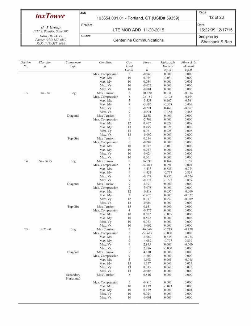
Maximum Member Forces
Section
No.
Elevation
ft
Component
Type
Condition Gov.
Load
Comb.
Force
K
Major Axis
Moment
kip-ft
Minor Axis
Moment
kip-ft
T1 80 - 66 Leg Max Tension 3 4.395 -0.039 -0.041
Max. Compression 3 -6.496 -0.053 -0.052
Max. Mx 6 -0.893 -0.591 -0.019
Max. My 6 -1.318 -0.018 0.589
Max. Vy 2 0.920 -0.326 0.016
Max. Vx 2 -0.922 0.011 0.331
Diagonal Max Tension 5 2.504 0.000 0.000
Max. Compression 5 -2.963 0.000 0.000
Max. Mx 10 -0.235 -0.010 0.000
Max. Vy 10 0.009 0.000 0.000
Horizontal Max Tension 4 1.134 0.008 0.000
Max. Compression 8 -1.134 0.000 0.000
Max. Mx 13 -0.091 0.015 0.000
Max. My 4 -0.210 0.008 0.000
Max. Vy 13 0.021 0.015 0.000
Max. Vx 4 -0.000 0.000 0.000
Secondary
Horizontal
Max Tension 4 0.586 0.000 0.000
Max. Compression 8 -0.411 0.000 0.000
Max. Mx 10 0.191 0.084 0.000
Max. Vy 10 -0.063 0.000 0.000
Top Girt Max Tension 13 0.106 0.000 0.000
Max. Compression 1 0.000 0.000 0.000
Max. Mx 10 0.039 -0.022 0.000
Max. Vy 10 0.017 0.000 0.000
T2 66 - 54 Leg Max Tension 5 13.297 -0.007 -0.009
Max. Compression 5 -16.666 -0.060 -0.174
Max. Mx 5 13.268 0.183 0.075
Max. My 9 13.116 0.077 0.184
Max. Vy 5 -0.061 0.183 0.075
Max. Vx 9 -0.062 0.077 0.184
Diagonal Max Tension 6 2.084 0.000 0.000
Max. Compression 6 -2.141 0.000 0.000
Max. Mx 5 1.697 0.025 -0.003
Max. My 2 -2.065 -0.002 -0.005
Max. Vy 12 -0.015 0.021 0.004
Max. Vx 13 -0.002 0.000 0.000
Top Girt Max Tension 2 0.112 0.000 0.000
ttnnxxTToowweerrJob
103654.001.01 - Portland, CT (USID# 59359)
Page
12 of 20
B+T Group1717 S. Boulder, Suite 300
Project
LTE MOD ADD_11-20-2015
Date
16:22:39 12/17/15
Tulsa, OK 74119
Phone: (918) 587-4630
FAX: (918) 587-4630
Client
Centerline Communications Designed by
Shashank.S.Rao
Section
No.
Elevation
ft
Component
Type
Condition Gov.
Load
Comb.
Force
K
Major Axis
Moment
kip-ft
Minor Axis
Moment
kip-ft
Max. Compression 2 -0.046 0.000 0.000
Max. Mx 10 0.034 -0.031 0.000
Max. My 10 0.034 0.000 0.002
Max. Vy 10 -0.023 0.000 0.000
Max. Vx 10 -0.001 0.000 0.000
T3 54 - 24 Leg Max Tension 5 30.370 0.031 -0.014
Max. Compression 5 -36.159 -0.173 -0.194
Max. Mx 5 -3.553 0.467 -0.361
Max. My 9 -3.596 -0.358 0.465
Max. Vy 5 -0.221 0.467 -0.361
Max. Vx 9 -0.221 -0.358 0.465
Diagonal Max Tension 6 2.658 0.000 0.000
Max. Compression 6 -2.709 0.000 0.000
Max. Mx 12 0.407 0.029 0.008
Max. My 13 0.495 0.026 0.008
Max. Vy 13 0.021 0.028 0.008
Max. Vx 13 -0.002 0.000 0.000
Top Girt Max Tension 6 0.214 0.000 0.000
Max. Compression 6 -0.207 0.000 0.000
Max. Mx 10 0.037 -0.041 0.000
Max. My 10 0.037 0.000 0.002
Max. Vy 10 -0.024 0.000 0.000
Max. Vx 10 0.001 0.000 0.000
T4 24 - 14.75 Leg Max Tension 5 36.092 0.164 0.159
Max. Compression 5 -42.814 0.091 0.001
Max. Mx 5 -4.433 0.835 -0.774
Max. My 9 -4.433 -0.777 0.839
Max. Vy 5 -0.174 0.835 -0.774
Max. Vx 9 -0.174 -0.777 0.839
Diagonal Max Tension 9 3.391 0.000 0.000
Max. Compression 9 -3.078 0.000 0.000
Max. Mx 12 -0.518 0.057 -0.009
Max. My 2 -2.626 0.003 -0.022
Max. Vy 12 0.031 0.057 -0.009
Max. Vx 13 -0.004 0.000 0.000
Top Girt Max Tension 13 0.651 0.000 0.000
Max. Compression 4 -0.577 0.000 0.000
Max. Mx 10 0.502 -0.085 0.000
Max. My 10 0.502 0.000 0.005
Max. Vy 10 0.033 0.000 0.000
Max. Vx 10 -0.002 0.000 0.000
T5 14.75 - 0 Leg Max Tension 5 46.066 -0.219 -0.178
Max. Compression 5 -53.687 -0.000 0.000
Max. Mx 5 -4.082 0.835 -0.774
Max. My 9 -4.082 -0.777 0.839
Max. Vy 9 2.895 0.000 -0.000
Max. Vx 5 2.886 -0.000 0.000
Diagonal Max Tension 9 4.170 0.000 0.000
Max. Compression 9 -4.609 0.000 0.000
Max. Mx 5 1.998 0.061 -0.015
Max. My 13 1.377 0.060 0.025
Max. Vy 13 0.033 0.060 0.025
Max. Vx 13 -0.005 0.000 0.000
Secondary
Horizontal
Max Tension 5 0.816 0.000 0.000
Max. Compression 5 -0.816 0.000 0.000
Max. Mx 10 0.139 -0.073 0.000
Max. My 10 0.139 0.000 0.004
Max. Vy 10 0.024 0.000 0.000
Max. Vx 10 -0.001 0.000 0.000

ttnnxxTToowweerrJob
103654.001.01 - Portland, CT (USID# 59359)
Page
13 of 20
B+T Group1717 S. Boulder, Suite 300
Project
LTE MOD ADD_11-20-2015
Date
16:22:39 12/17/15
Tulsa, OK 74119
Phone: (918) 587-4630
FAX: (918) 587-4630
Client
Centerline Communications Designed by
Shashank.S.Rao
Maximum Reactions
Location Condition Gov.
Load
Comb.
Vertical
K
Horizontal, X
K
Horizontal, Z
K
Leg D Max. Vert 7 50.006 5.641 -5.361
Max. Hx 7 50.006 5.641 -5.361
Max. Hz 3 -44.225 -5.048 4.813
Min. Vert 3 -44.225 -5.048 4.813
Min. Hx 3 -44.225 -5.048 4.813
Min. Hz 7 50.006 5.641 -5.361
Leg C Max. Vert 5 53.198 -5.405 -6.037
Max. Hx 9 -45.105 4.813 5.295
Max. Hz 9 -45.105 4.813 5.295
Min. Vert 9 -45.105 4.813 5.295
Min. Hx 5 53.198 -5.405 -6.037
Min. Hz 5 53.198 -5.405 -6.037
Leg B Max. Vert 3 51.797 -5.436 5.715
Max. Hx 7 -42.434 4.738 -4.973
Max. Hz 3 51.797 -5.436 5.715
Min. Vert 7 -42.434 4.738 -4.973
Min. Hx 3 51.797 -5.436 5.715
Min. Hz 7 -42.434 4.738 -4.973
Leg A Max. Vert 9 52.677 6.015 5.383
Max. Hx 9 52.677 6.015 5.383
Max. Hz 9 52.677 6.015 5.383
Min. Vert 5 -45.626 -5.317 -4.835
Min. Hx 5 -45.626 -5.317 -4.835
Min. Hz 5 -45.626 -5.317 -4.835
Tower Mast Reaction Summary
Load
Combination
Vertical
K
Shearx
K
Shearz
K
Overturning
Moment, Mx kip-ft
Overturning
Moment, Mz kip-ft
Torque
kip-ft
Dead Only 15.144 0.000 -0.000 -8.361 -15.219 0.000
Dead+Wind 0 deg - No Ice 15.144 -0.245 -16.333 -818.852 3.736 13.665
Dead+Wind 45 deg - No Ice 15.144 12.916 -12.916 -628.719 -635.577 6.781
Dead+Wind 90 deg - No Ice 15.144 16.333 0.245 10.594 -825.711 -5.693
Dead+Wind 135 deg - No Ice 15.144 13.262 13.262 638.803 -662.383 -14.665
Dead+Wind 180 deg - No Ice 15.144 0.245 16.333 802.130 -34.174 -13.665
Dead+Wind 225 deg - No Ice 15.144 -12.916 12.916 611.997 605.138 -6.781
Dead+Wind 270 deg - No Ice 15.144 -16.333 -0.245 -27.316 795.272 5.693
Dead+Wind 315 deg - No Ice 15.144 -13.262 -13.262 -655.525 631.945 14.665
Dead+Ice+Temp 27.961 0.000 -0.000 -13.805 -33.377 0.000
Dead+Wind 0 deg+Ice+Temp 27.961 -0.051 -4.284 -226.741 -29.432 3.269
Dead+Wind 45 deg+Ice+Temp 27.961 3.406 -3.406 -177.565 -197.138 1.352
Dead+Wind 90 deg+Ice+Temp 27.961 4.284 0.051 -9.859 -246.314 -1.694
Dead+Wind 135 deg+Ice+Temp 27.961 3.478 3.478 155.536 -202.718 -3.709
Dead+Wind 180 deg+Ice+Temp 27.961 0.051 4.284 199.131 -37.323 -3.269
Dead+Wind 225 deg+Ice+Temp 27.961 -3.406 3.406 149.956 130.383 -1.352
Dead+Wind 270 deg+Ice+Temp 27.961 -4.284 -0.051 -17.750 179.559 1.694
Dead+Wind 315 deg+Ice+Temp 27.961 -3.478 -3.478 -183.145 135.963 3.709
Dead+Wind 0 deg - Service 15.144 -0.085 -5.652 -288.808 -8.660 4.728
Dead+Wind 45 deg - Service 15.144 4.469 -4.469 -223.018 -229.876 2.346
Dead+Wind 90 deg - Service 15.144 5.652 0.085 -1.802 -295.666 -1.970

ttnnxxTToowweerrJob
103654.001.01 - Portland, CT (USID# 59359)
Page
14 of 20
B+T Group1717 S. Boulder, Suite 300
Project
LTE MOD ADD_11-20-2015
Date
16:22:39 12/17/15
Tulsa, OK 74119
Phone: (918) 587-4630
FAX: (918) 587-4630
Client
Centerline Communications Designed by
Shashank.S.Rao
Load
Combination
Vertical
K
Shearx
K
Shearz
K
Overturning
Moment, Mx kip-ft
Overturning
Moment, Mz kip-ft
Torque
kip-ft
Dead+Wind 135 deg - Service 15.144 4.589 4.589 215.571 -239.151 -5.074
Dead+Wind 180 deg - Service 15.144 0.085 5.652 272.086 -21.778 -4.728
Dead+Wind 225 deg - Service 15.144 -4.469 4.469 206.296 199.437 -2.346
Dead+Wind 270 deg - Service 15.144 -5.652 -0.085 -14.920 265.228 1.970
Dead+Wind 315 deg - Service 15.144 -4.589 -4.589 -232.293 208.713 5.074
Solution Summary
Load
Comb.
Sum of Applied Forces Sum of Reactions
% Error PX
K
PY
K
PZ
K
PX
K
PY
K
PZ
K
1 0.000 -15.144 0.000 -0.000 15.144 0.000 0.000%
2 -0.245 -15.144 -16.333 0.245 15.144 16.333 0.000%
3 12.916 -15.144 -12.916 -12.916 15.144 12.916 0.000%
4 16.333 -15.144 0.245 -16.333 15.144 -0.245 0.000%
5 13.262 -15.144 13.262 -13.262 15.144 -13.262 0.000%
6 0.245 -15.144 16.333 -0.245 15.144 -16.333 0.000%
7 -12.916 -15.144 12.916 12.916 15.144 -12.916 0.000%
8 -16.333 -15.144 -0.245 16.333 15.144 0.245 0.000%
9 -13.262 -15.144 -13.262 13.262 15.144 13.262 0.000%
10 0.000 -27.961 0.000 -0.000 27.961 0.000 0.000%
11 -0.051 -27.961 -4.284 0.051 27.961 4.284 0.000%
12 3.406 -27.961 -3.406 -3.406 27.961 3.406 0.000%
13 4.284 -27.961 0.051 -4.284 27.961 -0.051 0.000%
14 3.478 -27.961 3.478 -3.478 27.961 -3.478 0.000%
15 0.051 -27.961 4.284 -0.051 27.961 -4.284 0.000%
16 -3.406 -27.961 3.406 3.406 27.961 -3.406 0.000%
17 -4.284 -27.961 -0.051 4.284 27.961 0.051 0.000%
18 -3.478 -27.961 -3.478 3.478 27.961 3.478 0.000%
19 -0.085 -15.144 -5.652 0.085 15.144 5.652 0.000%
20 4.469 -15.144 -4.469 -4.469 15.144 4.469 0.000%
21 5.652 -15.144 0.085 -5.652 15.144 -0.085 0.000%
22 4.589 -15.144 4.589 -4.589 15.144 -4.589 0.000%
23 0.085 -15.144 5.652 -0.085 15.144 -5.652 0.000%
24 -4.469 -15.144 4.469 4.469 15.144 -4.469 0.000%
25 -5.652 -15.144 -0.085 5.652 15.144 0.085 0.000%
26 -4.589 -15.144 -4.589 4.589 15.144 4.589 0.000%
Maximum Tower Deflections - Service Wind
Section
No.
Elevation
ft
Horz.
Deflection
in
Gov.
Load
Comb.
Tilt
°
Twist
°
T1 80 - 66 0.560 20 0.052 0.013
T2 66 - 54 0.401 20 0.049 0.010
T3 54 - 24 0.282 20 0.040 0.007
T4 24 - 14.75 0.069 22 0.019 0.002
T5 14.75 - 0 0.032 22 0.011 0.001
Critical Deflections and Radius of Curvature - Service Wind

ttnnxxTToowweerrJob
103654.001.01 - Portland, CT (USID# 59359)
Page
15 of 20
B+T Group1717 S. Boulder, Suite 300
Project
LTE MOD ADD_11-20-2015
Date
16:22:39 12/17/15
Tulsa, OK 74119
Phone: (918) 587-4630
FAX: (918) 587-4630
Client
Centerline Communications Designed by
Shashank.S.Rao
Elevation
ft
Appurtenance Gov.
Load
Comb.
Deflection
in
Tilt
°
Twist
°
Radius of
Curvature
ft
84' Lighting Rod 5/8'' x 8' 20 0.560 0.052 0.013 258212
77'6'' (2) 800 10121 20 0.531 0.052 0.012 258212
75'6'' DC6-48-60-18-8F 20 0.508 0.052 0.012 258212
68' Dual Ring Halo 20 0.423 0.050 0.010 109346
51' Cat walk 22 0.255 0.038 0.007 93907
Maximum Tower Deflections - Design Wind
Section
No.
Elevation
ft
Horz.
Deflection
in
Gov.
Load
Comb.
Tilt
°
Twist
°
T1 80 - 66 1.578 5 0.142 0.037
T2 66 - 54 1.140 5 0.134 0.028
T3 54 - 24 0.806 5 0.111 0.021
T4 24 - 14.75 0.198 5 0.055 0.006
T5 14.75 - 0 0.094 5 0.032 0.004
Critical Deflections and Radius of Curvature - Design Wind
Elevation
ft
Appurtenance Gov.
Load
Comb.
Deflection
in
Tilt
°
Twist
°
Radius of
Curvature
ft
84' Lighting Rod 5/8'' x 8' 5 1.578 0.142 0.037 103310
77'6'' (2) 800 10121 5 1.498 0.142 0.035 103310
75'6'' DC6-48-60-18-8F 5 1.434 0.141 0.034 103310
68' Dual Ring Halo 5 1.200 0.137 0.029 43722
51' Cat walk 5 0.729 0.106 0.019 35747
Bolt Design Data
Section
No.
Elevation
ft
Component
Type
Bolt
Grade
Bolt Size
in
Number
Of
Bolts
Maximum
Load per
Bolt
K
Allowable
Load
K
Ratio
Load
Allowable
Allowable
Ratio
Criteria
T1 80 Leg A325N 0.625 12 1.083 12.885 0.084
1.333 Bolt DS
Diagonal A325N 0.625 2 1.252 4.792 0.261
1.333 Member Block
Shear
Horizontal A325N 0.625 2 0.567 6.443 0.088
1.333 Bolt Shear
Top Girt A325N 0.625 2 0.049 4.112 0.012
1 Member Block
Shear
T2 66 Leg A325N 0.625 12 2.778 12.885 0.216
1.333 Bolt DS
Diagonal A325N 0.625 2 1.042 4.792 0.217
1.333 Member Block
Shear
Top Girt A325N 0.625 1 0.112 5.098 0.022
1.333 Member Bearing
T3 54 Leg A325N 0.625 12 6.027 12.885 0.468
1.333 Bolt DS

ttnnxxTToowweerrJob
103654.001.01 - Portland, CT (USID# 59359)
Page
16 of 20
B+T Group1717 S. Boulder, Suite 300
Project
LTE MOD ADD_11-20-2015
Date
16:22:39 12/17/15
Tulsa, OK 74119
Phone: (918) 587-4630
FAX: (918) 587-4630
Client
Centerline Communications Designed by
Shashank.S.Rao
Section
No.
Elevation
ft
Component
Type
Bolt
Grade
Bolt Size
in
Number
Of
Bolts
Maximum
Load per
Bolt
K
Allowable
Load
K
Ratio
Load
Allowable
Allowable
Ratio
Criteria
Diagonal A325N 0.625 2 1.329 4.792 0.277
1.333 Member Block
Shear
Top Girt A325N 0.625 2 0.107 4.792 0.022
1.333 Member Block
Shear
T4 24 Diagonal A325N 0.625 2 1.696 5.132 0.330
1.333 Member Block
Shear
Top Girt A325N 0.625 2 0.260 4.792 0.054
1 Member Block
Shear
T5 14.75 Leg A36 1.250 4 11.517 23.488 0.490
1.333 Bolt Tension
Diagonal A325N 0.625 2 2.085 5.132 0.406
1.333 Member Block
Shear
Secondary
Horizontal
A325N 0.625 1 0.816 2.130 0.383
1.333 Member Block
Shear
Compression Checks
Leg Design Data (Compression)
Section
No.
Elevation
ft
Size L
ft
Lu
ft
Kl/r Fa
ksi
A
in2
Actual
P
K
Allow.
Pa
K
Ratio
P
Pa
T1 80 - 66 L4x4x3/8 14' 3'6'' 53.3
K=1.00
18.056 2.860 -6.496 51.639 0.126
T2 66 - 54 L4x4x3/8 12'1/2'' 6'1/4'' 91.7
K=1.00
14.003 2.860 -16.666 40.048 0.416
T3 54 - 24 L5x5x7/16 30'1-1/4'' 7'6-5/16'' 91.6
K=1.00
14.014 4.180 -36.159 58.579 0.617
T4 24 - 14.75 L5x5x7/16 9'3-3/8'' 9'3-3/8'' 113.0
K=1.00
11.269 4.180 -42.814 47.103 0.909
T5 14.75 - 0 L5x5x7/16 14'9-5/8'' 7'10-17/3
2''
95.9
K=1.00
13.494 4.180 -53.687 56.403 0.952
Diagonal Design Data (Compression)
Section
No.
Elevation
ft
Size L
ft
Lu
ft
Kl/r Fa
ksi
A
in2
Actual
P
K
Allow.
Pa
K
Ratio
P
Pa
T1 80 - 66 L2 1/2x2x3/16 4'4-31/32'
'
3'8-29/32'
'
112.6
K=1.07
11.319 0.809 -2.963 9.157 0.324
T2 66 - 54 L2 1/2x2x3/16 8'9-11/16'
'
4'2-5/8'' 119.0
K=1.00
10.432 0.809 -2.038 8.440 0.241
T3 54 - 24 L2 1/2x2x3/16 12'5-1/16'
'
6'11/32'' 157.7
K=0.93
6.004 0.809 -2.709 4.857 0.558
T4 24 - 14.75 L3x3x3/16 14'3-15/3
2''
7'3/8'' 136.5
K=0.96
8.016 1.090 -3.078 8.737 0.352

ttnnxxTToowweerrJob
103654.001.01 - Portland, CT (USID# 59359)
Page
17 of 20
B+T Group1717 S. Boulder, Suite 300
Project
LTE MOD ADD_11-20-2015
Date
16:22:39 12/17/15
Tulsa, OK 74119
Phone: (918) 587-4630
FAX: (918) 587-4630
Client
Centerline Communications Designed by
Shashank.S.Rao
Section
No.
Elevation
ft
Size L
ft
Lu
ft
Kl/r Fa
ksi
A
in2
Actual
P
K
Allow.
Pa
K
Ratio
P
Pa
T5 14.75 - 0 L3x3x3/16 19'1-7/8'' 9'11-5/32'
'
199.9
K=1.00
3.737 1.090 -4.609 4.073 1.132
Horizontal Design Data (Compression)
Section
No.
Elevation
ft
Size L
ft
Lu
ft
Kl/r Fa
ksi
A
in2
Actual
P
K
Allow.
Pa
K
Ratio
P
Pa
T1 80 - 66 L3 1/2x3 1/2x1/4 5'4-1/2'' 4'7-3/4'' 85.6
K=1.67
14.723 1.690 -1.134 24.883 0.046
Secondary Horizontal Design Data (Compression)
Section
No.
Elevation
ft
Size L
ft
Lu
ft
Kl/r Fa
ksi
A
in2
Actual
P
K
Allow.
Pa
K
Ratio
P
Pa
T1 80 - 66 2L4x4x1/4x3/8 5'4-1/2'' 5'1/2'' 84.2
K=1.74
14.536 3.880 -0.411 56.398 0.007
T5 14.75 - 0 L1 1/2x1 1/2x1/8 12'2-3/4'' 11'9-3/4'' 239.3
K=0.50
2.608 0.359 -0.816 0.937 0.871
Top Girt Design Data (Compression)
Section
No.
Elevation
ft
Size L
ft
Lu
ft
Kl/r Fa
ksi
A
in2
Actual
P
K
Allow.
Pa
K
Ratio
P
Pa
T2 66 - 54 L3x3x3/16 5'4-1/2'' 4'9-5/8'' 108.3
K=1.12
11.728 1.090 -0.046 12.784 0.004
T3 54 - 24 L2 1/2x2 1/2x3/16 6'9-1/2'' 6'3/4'' 136.6
K=0.93
8.005 0.902 -0.207 7.220 0.029
T4 24 - 14.75 L2 1/2x2x3/16 10'4'' 9'6-1/4'' 210.8
K=0.79
3.362 0.809 -0.577 2.720 0.212
KL/R > 200 (C) - 122
Tension Checks
Leg Design Data (Tension)

ttnnxxTToowweerrJob
103654.001.01 - Portland, CT (USID# 59359)
Page
18 of 20
B+T Group1717 S. Boulder, Suite 300
Project
LTE MOD ADD_11-20-2015
Date
16:22:39 12/17/15
Tulsa, OK 74119
Phone: (918) 587-4630
FAX: (918) 587-4630
Client
Centerline Communications Designed by
Shashank.S.Rao
Section
No.
Elevation
ft
Size L
ft
Lu
ft
Kl/r Fa
ksi
A
in2
Actual
P
K
Allow.
Pa
K
Ratio
P
Pa
T1 80 - 66 L4x4x3/8 14' 3'6'' 34.1 21.600 2.860 4.395 61.776 0.071
T2 66 - 54 L4x4x3/8 12'1/2'' 6'1/4'' 58.7 21.600 2.860 13.297 61.776 0.215
T3 54 - 24 L5x5x7/16 30'1-1/4'' 7'6-5/16'' 58.3 21.600 4.180 30.369 90.288 0.336
T4 24 - 14.75 L5x5x7/16 9'3-3/8'' 9'3-3/8'' 71.9 21.600 4.180 36.092 90.288 0.400
T5 14.75 - 0 L5x5x7/16 14'9-5/8'' 1'' 0.6 21.600 4.180 46.066 90.288 0.510
Diagonal Design Data (Tension)
Section
No.
Elevation
ft
Size L
ft
Lu
ft
Kl/r Fa
ksi
A
in2
Actual
P
K
Allow.
Pa
K
Ratio
P
Pa
T1 80 - 66 L2 1/2x2x3/16 4'4-31/32'
'
3'8-29/32'
'
82.8 29.000 0.501 2.504 14.537 0.172
T2 66 - 54 L2 1/2x2x3/16 8'3-21/32'
'
3'11-25/3
2''
83.6 29.000 0.501 2.084 14.537 0.143
T3 54 - 24 L2 1/2x2x3/16 11'3/4'' 5'4-1/2'' 111.5 29.000 0.501 2.658 14.537 0.183
T4 24 - 14.75 L3x3x3/16 14'3-15/3
2''
7'3/8'' 92.4 29.000 0.712 3.391 20.649 0.164
T5 14.75 - 0 L3x3x3/16 19'1-7/8'' 9'11-5/32'
'
126.9 29.000 0.712 4.170 20.649 0.202
Horizontal Design Data (Tension)
Section
No.
Elevation
ft
Size L
ft
Lu
ft
Kl/r Fa
ksi
A
in2
Actual
P
K
Allow.
Pa
K
Ratio
P
Pa
T1 80 - 66 L3 1/2x3 1/2x1/4 5'4-1/2'' 4'7-3/4'' 55.5 29.000 1.127 1.134 32.679 0.035
Secondary Horizontal Design Data (Tension)
Section
No.
Elevation
ft
Size L
ft
Lu
ft
Kl/r Fa
ksi
A
in2
Actual
P
K
Allow.
Pa
K
Ratio
P
Pa
T1 80 - 66 2L4x4x1/4x3/8 5'4-1/2'' 5'1/2'' 48.4 21.600 3.880 0.586 83.808 0.007
T5 14.75 - 0 L1 1/2x1 1/2x1/8 12'2-3/4'' 11'9-3/4'' 304.7 29.000 0.199 0.816 5.777 0.141

ttnnxxTToowweerrJob
103654.001.01 - Portland, CT (USID# 59359)
Page
19 of 20
B+T Group1717 S. Boulder, Suite 300
Project
LTE MOD ADD_11-20-2015
Date
16:22:39 12/17/15
Tulsa, OK 74119
Phone: (918) 587-4630
FAX: (918) 587-4630
Client
Centerline Communications Designed by
Shashank.S.Rao
Section
No.
Elevation
ft
Size L
ft
Lu
ft
Kl/r Fa
ksi
A
in2
Actual
P
K
Allow.
Pa
K
Ratio
P
Pa
Top Girt Design Data (Tension)
Section
No.
Elevation
ft
Size L
ft
Lu
ft
Kl/r Fa
ksi
A
in2
Actual
P
K
Allow.
Pa
K
Ratio
P
Pa
T1 80 - 66 L2x2x3/16 5'4-1/2'' 4'7-3/4'' 98.1 29.000 0.431 0.098 12.493 0.008*
T2 66 - 54 L3x3x3/16 5'4-1/2'' 4'9-5/8'' 64.4 29.000 0.712 0.112 20.649 0.005
T3 54 - 24 L2 1/2x2 1/2x3/16 6'9-1/2'' 6'3/4'' 99.6 29.000 0.571 0.214 16.560 0.013
T4 24 - 14.75 L2 1/2x2x3/16 10'4'' 9'6-1/4'' 198.4 29.000 0.501 0.520 14.537 0.036*
* DL controls
Section Capacity Table
Section
No.
Elevation
ft
Component
Type
Size Critical
Element
P
K
SF*Pallow
K
%
Capacity
Pass
Fail
T1 80 - 66 Leg L4x4x3/8 3 -6.496 68.835 9.4 Pass
T2 66 - 54 Leg L4x4x3/8 58 -16.666 53.385 31.2 Pass
T3 54 - 24 Leg L5x5x7/16 78 -36.159 78.086 46.3 Pass
T4 24 - 14.75 Leg L5x5x7/16 118 -42.814 62.788 68.2 Pass
T5 14.75 - 0 Leg L5x5x7/16 134 -53.687 75.186 71.4 Pass
T1 80 - 66 Diagonal L2 1/2x2x3/16 13 -2.963 12.206 24.3 Pass
T2 66 - 54 Diagonal L2 1/2x2x3/16 63 -2.038 11.250 18.1 Pass
T3 54 - 24 Diagonal L2 1/2x2x3/16 87 -2.709 6.475 41.8 Pass
T4 24 - 14.75 Diagonal L3x3x3/16 128 -3.078 11.647 26.4 Pass
T5 14.75 - 0 Diagonal L3x3x3/16 142 -4.609 5.429 84.9 Pass
T1 80 - 66 Horizontal L3 1/2x3 1/2x1/4 43 -1.134 33.168 3.4
6.6 (b)
Pass
T1 80 - 66 Secondary Horizontal 2L4x4x1/4x3/8 35 -0.411 75.179 0.5 Pass
T5 14.75 - 0 Secondary Horizontal L1 1/2x1 1/2x1/8 146 -0.816 1.249 65.3 Pass
T1 80 - 66 Top Girt L2x2x3/16 6 0.098 12.493 0.8
0.9 (b)
Pass
T2 66 - 54 Top Girt L3x3x3/16 23 0.112 27.525 0.4
1.6 (b)
Pass
T3 54 - 24 Top Girt L2 1/2x2 1/2x3/16 83 -0.207 9.624 2.2 Pass
T4 24 - 14.75 Top Girt L2 1/2x2x3/16 122 -0.577 3.626 15.9 Pass
Summary
Leg (T5) 71.4 Pass
Diagonal
(T5)
84.9 Pass
Horizontal
(T1)
6.6 Pass
Secondary
Horizontal
(T5)
65.3 Pass
Top Girt 15.9 Pass

ttnnxxTToowweerrJob
103654.001.01 - Portland, CT (USID# 59359)
Page
20 of 20
B+T Group1717 S. Boulder, Suite 300
Project
LTE MOD ADD_11-20-2015
Date
16:22:39 12/17/15
Tulsa, OK 74119
Phone: (918) 587-4630
FAX: (918) 587-4630
Client
Centerline Communications Designed by
Shashank.S.Rao
Section
No.
Elevation
ft
Component
Type
Size Critical
Element
P
K
SF*Pallow
K
%
Capacity
Pass
Fail
(T4)
Bolt Checks 36.8 Pass
RATING = 84.9 Pass
Program Version 6.1.4.1

at&tMOBILITY
SITE NUMBER: CT1066SITE NAME: PORTLAND
AT&T
VICINITY MAP
at&tMOBILITY
FA CODE: 10035005SITE NUMBER: CT1066SITE NAME: PORTLAND
PROJECT TEAM
DRAWING INDEX REV.
APPROVALS
GENERAL NOTES
CLIENT REPRESENTATIVE
SITE ACQUISITION:
RF ENGINEER:
CONSTRUCTION MANAGEMENT:
PROJECT INFORMATION
ENGINEERING

at&tMOBILITY
SITE NUMBER: CT1066SITE NAME: PORTLAND
AT&T

at&tMOBILITY
SITE NUMBER: CT1066SITE NAME: PORTLAND
AT&T
COMPOUND LAYOUT
NORTH

at&tMOBILITY
SITE NUMBER: CT1066SITE NAME: PORTLAND
AT&T
EXISTING EQUIPMENT LAYOUT
NORTH
PROPOSED EQUIPMENT LAYOUT
NORTH

at&tMOBILITY
SITE NUMBER: CT1066SITE NAME: PORTLAND
AT&T
EXISTING ANTENNA LAYOUT
PROPOSED ANTENNA LAYOUT
PROPOSED TOWER ELEVATION
NORTH
NORTH
EXISTING TOWER ELEVATION
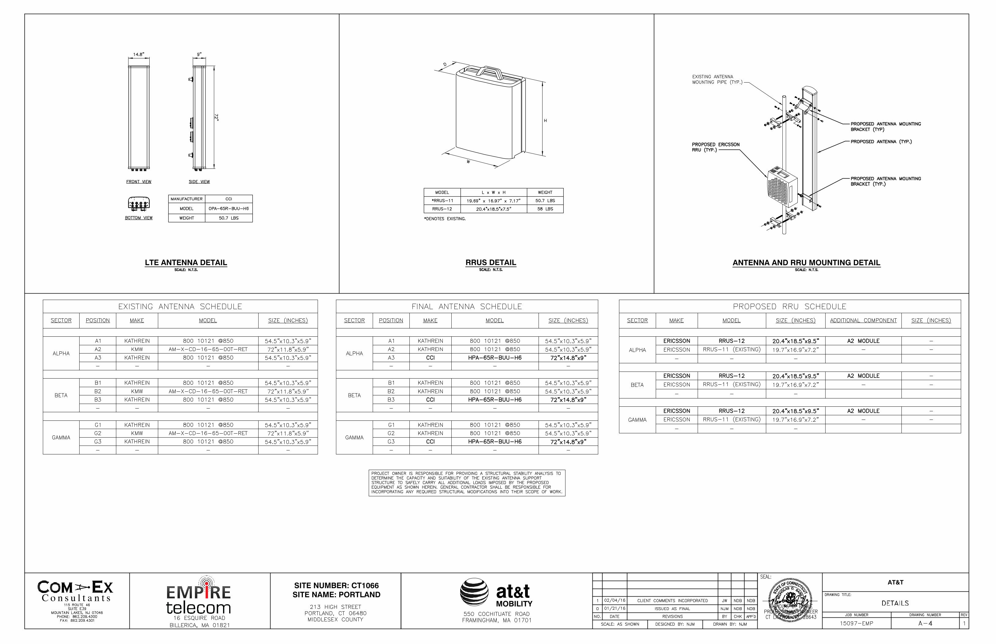
at&tMOBILITY
SITE NUMBER: CT1066SITE NAME: PORTLAND
AT&T
RRUS DETAILLTE ANTENNA DETAIL ANTENNA AND RRU MOUNTING DETAIL

at&tMOBILITY
SITE NUMBER: CT1066SITE NAME: PORTLAND
AT&T
TYPICAL PLUMBING DIAGRAM (PER SECTOR)
GROUND WIRE TO GROUND BAR CONNECTION DETAIL
GROUND BAR DETAIL
GROUNDING RISER DIAGRAM
TYPICAL GROUND BAR CONNECTION DETAIL