MG3690C Synthesizer Technical Data Sheet · MG3690C Signal Generator Specifications MG3690C TDS PN:...
24
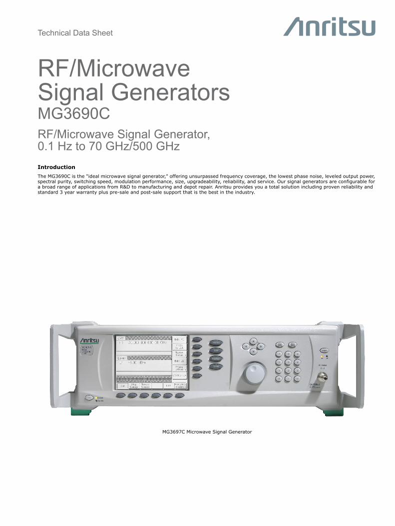
Technical Data Sheet RF/Microwave Signal Generators MG3690C RF/Microwave Signal Generator, 0.1 Hz to 70 GHz/500 GHz Introduction The MG3690C is the "ideal microwave signal generator," offering unsurpassed frequency coverage, the lowest phase noise, leveled output power, spectral purity, switching speed, modulation performance, size, upgradeability, reliability, and service. Our signal generators are configurable for a broad range of applications from R&D to manufacturing and depot repair. Anritsu provides you a total solution including proven reliability and standard 3 year warranty plus pre-sale and post-sale support that is the best in the industry. MG3697C Microwave Signal Generator
Transcript of MG3690C Synthesizer Technical Data Sheet · MG3690C Signal Generator Specifications MG3690C TDS PN:...
Technical Data Sheet
RF/Microwave Signal GeneratorsMG3690CRF/Microwave Signal Generator,0.1 Hz to 70 GHz/500 GHz
IntroductionThe MG3690C is the "ideal microwave signal generator," offering unsurpassed frequency coverage, the lowest phase noise, leveled output power, spectral purity, switching speed, modulation performance, size, upgradeability, reliability, and service. Our signal generators are configurable for a broad range of applications from R&D to manufacturing and depot repair. Anritsu provides you a total solution including proven reliability and standard 3 year warranty plus pre-sale and post-sale support that is the best in the industry.
MG3697C Microwave Signal Generator
2 PN: 11410-00515 Rev. P MG3690C TDS
Specifications MG3690C Signal Generator
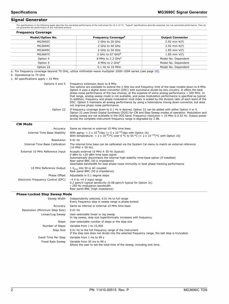
Signal Generator The specifications in the following pages describe the warranted performance of the instrument for 25 ± 10 °C. "Typical" specifications describe expected, but not warranted performance. They do not guarantee the performance of any individual product.
Frequency Coverage
Options 4 and 5 Frequency extension down to 8 MHzTwo options are available to extend the 2 GHz low end frequency limit of the base models down to 8 MHz. Option 4 uses a digital down-converter (DDC) with successive divide-by-two circuitry. It offers the best phase noise performance of the two choices, at the expense of some analog performance < 500 MHz. In that range, analog sweep mode is not available, and pulse modulation performance is specified as typical. In addition, frequency and phase modulation mod index is scaled by the division ratio of each band of the DDC. Option 5 maintains all analog performance by using a heterodyne mixing down-converter, but does not improve phase noise performance.
Option 22 If frequency coverage down to 0.1 Hz is desired, Option 22 can be added with either Option 4 or 5. Option 22 uses Direct Digital Synthesis (DDS) for CW and Step Sweep modes of operation. Modulation and analog sweep are not available in the DDS band. Frequency resolution < 10 MHz is 0.02 Hz. Output power across the complete instrument frequency range is degraded by 2 dB.
CW Mode Accuracy Same as internal or external 10 MHz time base
Internal Time Base Stability With aging: < 2 x 10⁻⁹/day (< 5 x 10⁻¹⁰/day with Option 16)With temperature: < 2 x 10⁻⁸/°C over 0 °C to 55 °C (< 2 x 10⁻¹⁰/°C with Option 16)
Resolution 0.01 HzInternal Time Base Calibration The internal time base can be calibrated via the System Cal menu to match an external reference
(10 MHz ± 50 Hz).External 10 MHz Reference Input Accepts external 10 MHz ± 50 Hz (typical)
0 dBm to +20 dBm time base signalAutomatically disconnects the internal high-stability time-base option (if installed)Rear panel BNC (50 Ω impedance)Selectable bandwidth for best phase noise immunity or best phase tracking performance
10 MHz Reference Output 1 Vp-p into 50 Ω, AC coupledRear panel BNC (50 Ω impedance)
Phase Offset Adjustable in 0.1 degree stepsElectronic Frequency Control (EFC) –4 V to +4 V input range
0.2 ppm/V typical sensitivity (0.08 ppm/V typical for Option 3x)≤ 250 Hz modulation bandwidthRear panel BNC (high impedance)
Phase-Locked Step Sweep Mode Sweep Width Independently selected, 0.01 Hz to full range
Every frequency step in sweep range is phase-locked.Accuracy Same as internal or external 10 MHz time base
Resolution (Minimum Step Size) 0.01 HzLinear/Log Sweep User-selectable linear or log sweep
In log sweep, step size logarithmically increases with frequency.Steps User-selectable number of steps or the step size
Number of Steps Variable from 1 to 10,000Step Size 0.01 Hz to the full frequency range of the instrument
If the step size does not divide into the selected frequency range, the last step is truncated.Dwell Time Per Step Variable from 1 ms to 99 s
Fixed Rate Sweep Variable from 30 ms to 99 sAllows the user to set the total time of the sweep, including lock time.
Model/Option No. Frequency Coveragea
a. For frequency coverage beyond 70 GHz, utilize millimeter-wave multiplier 2000-1694 series (see page 18).
Output ConnectorMG3692C 2 GHz to 20 GHz 2.92 mm K(f)MG3694C 2 GHz to 40 GHz 2.92 mm K(f)MG3695C 2 GHz to 50 GHz 1.85 mm V(f)MG3697C 2 GHz to 67 GHzb
b. Operational to 70 GHz
1.85 mm V(f)Option 4 8 MHz to 2.2 GHzc
c. All specifications apply ≥ 10 MHz
Model No. DependentOption 5 8 MHz to 2 GHzc Model No. DependentOption 22 0.1 Hz to 10 MHz Model No. Dependent
MG3690C Signal Generator Specifications
MG3690C TDS PN: 11410-00515 Rev. P 3
Analog Sweep Mode (Option 6) Sweep Width Independently selected from 1 MHz to full frequency range
For units with Option 4 (Digital Down Converter), the start frequency during analog sweep is limited to ≥ 2.2 GHz for stop frequencies > 20 GHz. For stop frequencies ≤ 20 GHz, the start frequency is limited to ≥ 500 MHz. A range error will be displayed if any of these analog sweep start/stop limits are exceeded.Analog sweep is not available < 10 MHz with Option 22.
Accuracy The lesser of ± 30 MHz or ± 2 MHz +0.25 % of sweep width for Sweep Speeds of ≤ 50 MHz/ms (typical)Sweep Time Range 30 ms to 99 s
Alternate Sweep Mode Sweeps alternately in step sweep between any two sweep ranges. Each sweep range may be associated with a power level.
Manual Sweep Mode Provides stepped, phase-locked adjustment of frequency between sweep limits.User-selectable number of steps or step size.
List Sweep Mode Under GPIB or Ethernet control, or via the front panel, up to 4 tables with 2000 non-sequential frequency/power sets can be stored and then addressed as a phase-locked step sweep. One table of 2000 points is stored in non-volatile memory. All other tables are stored in volatile memory.
Programmable Frequency Agility Under GPIB or Ethernet control, up to 3202 non-sequential frequency/power sets can be stored and then addressed as a phase-locked step sweep. Data is stored in volatile memory.
Markers Up to 20 independent, settable markers (F0 – F9 and M0 – M9)Video Markers +5 V or –5 V marker output, selectable from system menus
AUX I/O connector, rear panelIntensity Markers Produces an intensity dot on analog display traces, obtained by a momentary dwell in RF sweep, in analog
sweeps of < 1 second.Marker Accuracy Same as sweep frequency accuracy
Marker Resolution: Analog Sweep: 1 MHz or Sweep Width/4096, which ever is greaterStep Sweep: 0.01 Hz
Sweep Triggering Sweep triggering is provided for Analog Frequency Sweep, Step Frequency Sweep, List Frequency Sweep, and CW Power Sweep.
Auto Triggers sweep automaticallyExternal Triggers a sweep on the low to high transition of an external TTL signal.
AUX I/O connector, rear panelSingle Triggers, aborts, and resets a single sweep
Reset sweep may be selected to be at the top or bottom of the sweep.
General Stored Setups Stores front panel settings and nine additional front-panel setups in a non-volatile RAM. A system menu
allows saving and recalling of instrument setups. Whenever the instrument is turned on, control settings come on at the same functions and values existing when the instrument was turned off.
Memory Sequencing Input Accepts a TTL low-level signal to sequence through ten stored setups. AUX I/O connector, rear panel
Self-Test Instrument self-test is performed when Self-Test soft-key is selected. If an error is detected, an error message is displayed in a window on the LCD identifying the probable cause and remedy.
Secure Mode Disables all frequency and power level state displays. Stored setups saved in secure mode remain secured when recalled. Mode selectable from a system menu and via GPIB or Ethernet.
Parameter Entry Instrument-controlled parameters can be entered in multiple ways: keypad, rotary data knob, or the touch pads of the cursor-control key. Controlled parameters are frequency, power level, sweep time, dwell time, and number of steps. Keypad entries are terminated by pressing the appropriate soft key. Edits are terminated by exiting the edit menu.
Reset Returns all instrument parameters to predefined default states or values.Any pending GPIB or Ethernet I/O is aborted. Selectable from the system menu
Master/Slave Operation Allows two output signals to be swept with a user-selected frequency offset. One instrument controls the other via AUX I/O and SERIAL I/O connections. Requires a Master/Slave Interface Cable Set (part number ND36329).
User Level Flatness Correction Allows user to calibrate out path loss due to external switching and cables via entered power table from a GPIB power meter or calculated data. When user level correction is activated, entered power levels are delivered at the point where calibration was performed. Supported power meters are Anritsu ML2437A, ML2438A, ML2480A/B, ML2490A, and ML4803A and HP 437B, 438A, and 70100A. Five user tables are available with up to 801 points/table.
Warm Up Time: From Standby: 30 minutesFrom Cold Start (0 °C): 120 hours to achieve specified frequency stability with agingInstruments disconnected from AC line power for more than 72 hours require 30 days to return to specified frequency stability with aging.
Power 85 VAC to 264 VAC, 48 Hz to 440 Hz, 250 VA maximumStandby With AC line power connected, unit is placed in standby when front panel power switch is released from the
OPERATE position.Weight 18 kg maximum
Dimensions (WxHxD) 429 mm x 133 mm x 450 mm Warranty 3 years from ship date
4 PN: 11410-00515 Rev. P MG3690C TDS
Specifications MG3690C Signal Generator
Remote Operation All instrument functions, settings, and operating modes (except for power on/standby) are controllable using commands sent from an external computer via Ethernet (VXI-11 over TCP/IP) or GPIB (IEEE-488 interface bus).Note: For users who wish to use a USB control interface, the following adapter available from National Instruments is recommended:USB: NI GPIB-USB-MS
Ethernet Port 10/100 Base-TEthernet Address DHCP with Auto-IP 169.254.90.55 (default) or static 192.168.0.254
GPIB Address Selectable from a system menuGPIB Commands Native, SCPI
IEEE -488 Interface Function Subset Source Handshake: SH1Acceptor Handshake: AH1Talker: T6Listener: L4Service Request: SR1Remote/Local: RL1Parallel Poll: PP1Device Clear: DC1Device Trigger: DT1Controller Capability: C0, C1, C2, C3, C28Tri-State Driver: E2
GPIB Status Annunciators When the instrument is operating in Remote, the GPIB status annunciators (listed below) will appear in a window on the front panel LCD.
Remote Operating on the GPIB or via Ethernet, all instrument front panel keys are ignored, except for the SYSTEM key and the RETURN TO LOCAL soft key.
LLO (Local Lockout) Disables the RETURN TO LOCAL soft key. Instrument can be placed in local mode only via Ethernet or GPIB, or by cycling line power.
Emulations The instrument responds to the published GPIB commands and responses of the Anritsu Models 6600, 6700, and 6XX00-series signal sources. When emulating another signal source, the instrument will be limited to the capabilities, mnemonics, and parameter resolutions of the emulated instrument.
Environmental (MIL-PRF-28800F, class 3) Storage Temperature Range –40 °C to +75 °C
Operating Temperature Range 0 °C to +50 °CRelative Humidity 5 % to 95 % at 40 °C (non-condensing)
Altitude 4,600 m, 43.9 cm-HgVibration Random, 5 Hz to 500 Hz, 0.015 to 0.0039 g2/Hz PSD; Sinusoidal, 5 Hz to 55 Hz, 0.33 mm displacement
EMC IEC 61326-1:2013Safety IEC 61010-1:2010
MG3690C Signal Generator Specifications
MG3690C TDS PN: 11410-00515 Rev. P 5
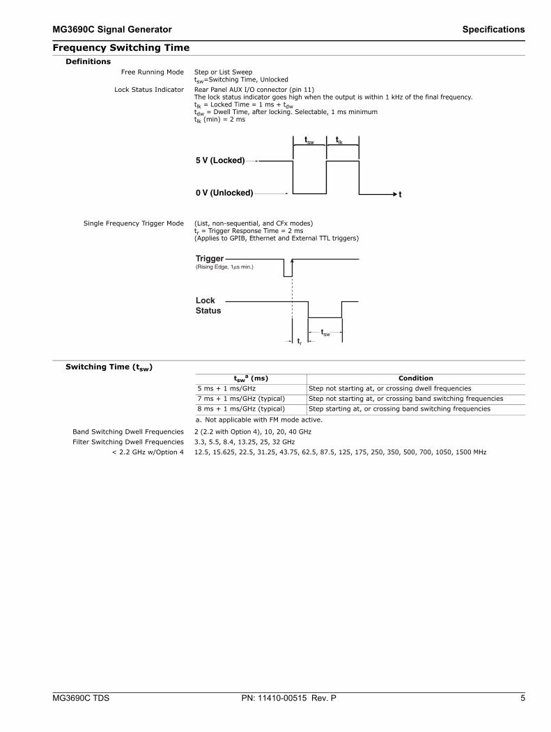
Frequency Switching Time Definitions
Free Running Mode Step or List Sweeptsw=Switching Time, Unlocked
Lock Status Indicator Rear Panel AUX I/O connector (pin 11) The lock status indicator goes high when the output is within 1 kHz of the final frequency.tlk = Locked Time = 1 ms + tdwtdw = Dwell Time, after locking. Selectable, 1 ms minimumtlk (min) = 2 ms
Single Frequency Trigger Mode (List, non-sequential, and CFx modes)tr = Trigger Response Time = 2 ms(Applies to GPIB, Ethernet and External TTL triggers)
Switching Time (tsw)
Band Switching Dwell Frequencies 2 (2.2 with Option 4), 10, 20, 40 GHzFilter Switching Dwell Frequencies 3.3, 5.5, 8.4, 13.25, 25, 32 GHz
< 2.2 GHz w/Option 4 12.5, 15.625, 22.5, 31.25, 43.75, 62.5, 87.5, 125, 175, 250, 350, 500, 700, 1050, 1500 MHz
tswa (ms)
a. Not applicable with FM mode active.
Condition5 ms + 1 ms/GHz Step not starting at, or crossing dwell frequencies7 ms + 1 ms/GHz (typical) Step not starting at, or crossing band switching frequencies8 ms + 1 ms/GHz (typical) Step starting at, or crossing band switching frequencies
6 PN: 11410-00515 Rev. P MG3690C TDS
Specifications MG3690C Signal Generator
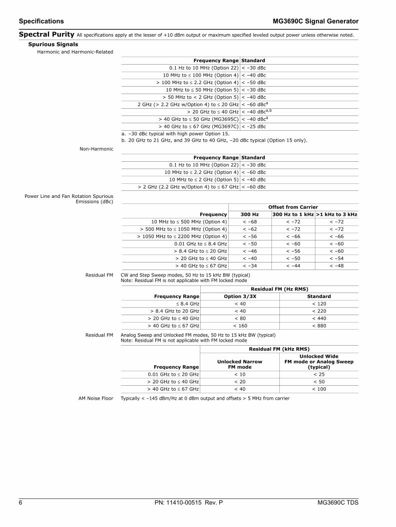
Spectral Purity All specifications apply at the lesser of +10 dBm output or maximum specified leveled output power unless otherwise noted.
Spurious Signals Harmonic and Harmonic-Related
Non-Harmonic
Power Line and Fan Rotation SpuriousEmissions (dBc)
Residual FM CW and Step Sweep modes, 50 Hz to 15 kHz BW (typical)Note: Residual FM is not applicable with FM locked mode
Residual FM Analog Sweep and Unlocked FM modes, 50 Hz to 15 kHz BW (typical)Note: Residual FM is not applicable with FM locked mode
AM Noise Floor Typically < –145 dBm/Hz at 0 dBm output and offsets > 5 MHz from carrier
Frequency Range Standard0.1 Hz to 10 MHz (Option 22) < –30 dBc
10 MHz to ≤ 100 MHz (Option 4) < –40 dBc> 100 MHz to ≤ 2.2 GHz (Option 4) < –50 dBc
10 MHz to ≤ 50 MHz (Option 5) < –30 dBc> 50 MHz to < 2 GHz (Option 5) < –40 dBc
2 GHz (> 2.2 GHz w/Option 4) to ≤ 20 GHz < –60 dBca
a. –30 dBc typical with high power Option 15.
> 20 GHz to ≤ 40 GHz < –40 dBca,b
b. 20 GHz to 21 GHz, and 39 GHz to 40 GHz, –20 dBc typical (Option 15 only).
> 40 GHz to ≤ 50 GHz (MG3695C) < –40 dBca
> 40 GHz to ≤ 67 GHz (MG3697C) < –25 dBc
Frequency Range Standard0.1 Hz to 10 MHz (Option 22) < –30 dBc
10 MHz to ≤ 2.2 GHz (Option 4) < –60 dBc10 MHz to ≤ 2 GHz (Option 5) < –40 dBc
> 2 GHz (2.2 GHz w/Option 4) to ≤ 67 GHz < –60 dBc
FrequencyOffset from Carrier
300 Hz 300 Hz to 1 kHz >1 kHz to 3 kHz10 MHz to ≤ 500 MHz (Option 4) < –68 < –72 < –72
> 500 MHz to ≤ 1050 MHz (Option 4) < –62 < –72 < –72> 1050 MHz to ≤ 2200 MHz (Option 4) < –56 < –66 < –66
0.01 GHz to ≤ 8.4 GHz < –50 < –60 < –60> 8.4 GHz to ≤ 20 GHz < –46 < –56 < –60> 20 GHz to ≤ 40 GHz < –40 < –50 < –54> 40 GHz to ≤ 67 GHz < –34 < –44 < –48
Frequency RangeResidual FM (Hz RMS)
Option 3/3X Standard≤ 8.4 GHz < 40 < 120
> 8.4 GHz to 20 GHz < 40 < 220> 20 GHz to ≤ 40 GHz < 80 < 440> 40 GHz to ≤ 67 GHz < 160 < 880
Frequency Range
Residual FM (kHz RMS)
Unlocked Narrow FM mode
Unlocked Wide FM mode or Analog Sweep
(typical)0.01 GHz to ≤ 20 GHz < 10 < 25> 20 GHz to ≤ 40 GHz < 20 < 50> 40 GHz to ≤ 67 GHz < 40 < 100
MG3690C Signal Generator Specifications
MG3690C TDS PN: 11410-00515 Rev. P 7
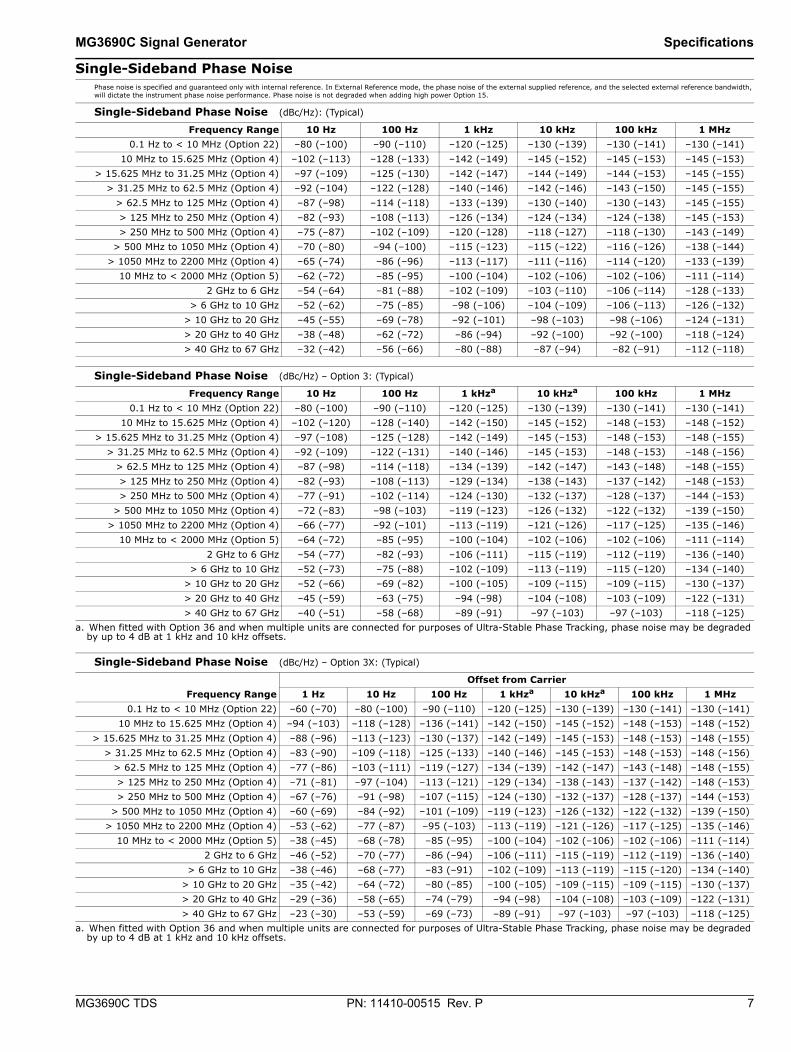
Single-Sideband Phase Noise Phase noise is specified and guaranteed only with internal reference. In External Reference mode, the phase noise of the external supplied reference, and the selected external reference bandwidth, will dictate the instrument phase noise performance. Phase noise is not degraded when adding high power Option 15.
Single-Sideband Phase Noise (dBc/Hz): (Typical)
Single-Sideband Phase Noise (dBc/Hz) – Option 3: (Typical)
Single-Sideband Phase Noise (dBc/Hz) – Option 3X: (Typical)
Frequency Range 10 Hz 100 Hz 1 kHz 10 kHz 100 kHz 1 MHz0.1 Hz to < 10 MHz (Option 22) –80 (–100) –90 (–110) –120 (–125) –130 (–139) –130 (–141) –130 (–141)
10 MHz to 15.625 MHz (Option 4) –102 (–113) –128 (–133) –142 (–149) –145 (–152) –145 (–153) –145 (–153)> 15.625 MHz to 31.25 MHz (Option 4) –97 (–109) –125 (–130) –142 (–147) –144 (–149) –144 (–153) –145 (–155)
> 31.25 MHz to 62.5 MHz (Option 4) –92 (–104) –122 (–128) –140 (–146) –142 (–146) –143 (–150) –145 (–155)> 62.5 MHz to 125 MHz (Option 4) –87 (–98) –114 (–118) –133 (–139) –130 (–140) –130 (–143) –145 (–155)> 125 MHz to 250 MHz (Option 4) –82 (–93) –108 (–113) –126 (–134) –124 (–134) –124 (–138) –145 (–153)> 250 MHz to 500 MHz (Option 4) –75 (–87) –102 (–109) –120 (–128) –118 (–127) –118 (–130) –143 (–149)
> 500 MHz to 1050 MHz (Option 4) –70 (–80) –94 (–100) –115 (–123) –115 (–122) –116 (–126) –138 (–144)> 1050 MHz to 2200 MHz (Option 4) –65 (–74) –86 (–96) –113 (–117) –111 (–116) –114 (–120) –133 (–139)
10 MHz to < 2000 MHz (Option 5) –62 (–72) –85 (–95) –100 (–104) –102 (–106) –102 (–106) –111 (–114)2 GHz to 6 GHz –54 (–64) –81 (–88) –102 (–109) –103 (–110) –106 (–114) –128 (–133)
> 6 GHz to 10 GHz –52 (–62) –75 (–85) –98 (–106) –104 (–109) –106 (–113) –126 (–132)> 10 GHz to 20 GHz –45 (–55) –69 (–78) –92 (–101) –98 (–103) –98 (–106) –124 (–131)> 20 GHz to 40 GHz –38 (–48) –62 (–72) –86 (–94) –92 (–100) –92 (–100) –118 (–124)> 40 GHz to 67 GHz –32 (–42) –56 (–66) –80 (–88) –87 (–94) –82 (–91) –112 (–118)
Frequency Range 10 Hz 100 Hz 1 kHza
a. When fitted with Option 36 and when multiple units are connected for purposes of Ultra-Stable Phase Tracking, phase noise may be degraded by up to 4 dB at 1 kHz and 10 kHz offsets.
10 kHza 100 kHz 1 MHz0.1 Hz to < 10 MHz (Option 22) –80 (–100) –90 (–110) –120 (–125) –130 (–139) –130 (–141) –130 (–141)
10 MHz to 15.625 MHz (Option 4) –102 (–120) –128 (–140) –142 (–150) –145 (–152) –148 (–153) –148 (–152)> 15.625 MHz to 31.25 MHz (Option 4) –97 (–108) –125 (–128) –142 (–149) –145 (–153) –148 (–153) –148 (–155)
> 31.25 MHz to 62.5 MHz (Option 4) –92 (–109) –122 (–131) –140 (–146) –145 (–153) –148 (–153) –148 (–156)> 62.5 MHz to 125 MHz (Option 4) –87 (–98) –114 (–118) –134 (–139) –142 (–147) –143 (–148) –148 (–155)> 125 MHz to 250 MHz (Option 4) –82 (–93) –108 (–113) –129 (–134) –138 (–143) –137 (–142) –148 (–153)> 250 MHz to 500 MHz (Option 4) –77 (–91) –102 (–114) –124 (–130) –132 (–137) –128 (–137) –144 (–153)
> 500 MHz to 1050 MHz (Option 4) –72 (–83) –98 (–103) –119 (–123) –126 (–132) –122 (–132) –139 (–150)> 1050 MHz to 2200 MHz (Option 4) –66 (–77) –92 (–101) –113 (–119) –121 (–126) –117 (–125) –135 (–146)
10 MHz to < 2000 MHz (Option 5) –64 (–72) –85 (–95) –100 (–104) –102 (–106) –102 (–106) –111 (–114)2 GHz to 6 GHz –54 (–77) –82 (–93) –106 (–111) –115 (–119) –112 (–119) –136 (–140)
> 6 GHz to 10 GHz –52 (–73) –75 (–88) –102 (–109) –113 (–119) –115 (–120) –134 (–140)> 10 GHz to 20 GHz –52 (–66) –69 (–82) –100 (–105) –109 (–115) –109 (–115) –130 (–137)> 20 GHz to 40 GHz –45 (–59) –63 (–75) –94 (–98) –104 (–108) –103 (–109) –122 (–131)> 40 GHz to 67 GHz –40 (–51) –58 (–68) –89 (–91) –97 (–103) –97 (–103) –118 (–125)
Frequency RangeOffset from Carrier
1 Hz 10 Hz 100 Hz 1 kHza
a. When fitted with Option 36 and when multiple units are connected for purposes of Ultra-Stable Phase Tracking, phase noise may be degraded by up to 4 dB at 1 kHz and 10 kHz offsets.
10 kHza 100 kHz 1 MHz0.1 Hz to < 10 MHz (Option 22) –60 (–70) –80 (–100) –90 (–110) –120 (–125) –130 (–139) –130 (–141) –130 (–141)
10 MHz to 15.625 MHz (Option 4) –94 (–103) –118 (–128) –136 (–141) –142 (–150) –145 (–152) –148 (–153) –148 (–152)> 15.625 MHz to 31.25 MHz (Option 4) –88 (–96) –113 (–123) –130 (–137) –142 (–149) –145 (–153) –148 (–153) –148 (–155)
> 31.25 MHz to 62.5 MHz (Option 4) –83 (–90) –109 (–118) –125 (–133) –140 (–146) –145 (–153) –148 (–153) –148 (–156)> 62.5 MHz to 125 MHz (Option 4) –77 (–86) –103 (–111) –119 (–127) –134 (–139) –142 (–147) –143 (–148) –148 (–155)> 125 MHz to 250 MHz (Option 4) –71 (–81) –97 (–104) –113 (–121) –129 (–134) –138 (–143) –137 (–142) –148 (–153)> 250 MHz to 500 MHz (Option 4) –67 (–76) –91 (–98) –107 (–115) –124 (–130) –132 (–137) –128 (–137) –144 (–153)
> 500 MHz to 1050 MHz (Option 4) –60 (–69) –84 (–92) –101 (–109) –119 (–123) –126 (–132) –122 (–132) –139 (–150)> 1050 MHz to 2200 MHz (Option 4) –53 (–62) –77 (–87) –95 (–103) –113 (–119) –121 (–126) –117 (–125) –135 (–146)
10 MHz to < 2000 MHz (Option 5) –38 (–45) –68 (–78) –85 (–95) –100 (–104) –102 (–106) –102 (–106) –111 (–114)2 GHz to 6 GHz –46 (–52) –70 (–77) –86 (–94) –106 (–111) –115 (–119) –112 (–119) –136 (–140)
> 6 GHz to 10 GHz –38 (–46) –68 (–77) –83 (–91) –102 (–109) –113 (–119) –115 (–120) –134 (–140)> 10 GHz to 20 GHz –35 (–42) –64 (–72) –80 (–85) –100 (–105) –109 (–115) –109 (–115) –130 (–137)> 20 GHz to 40 GHz –29 (–36) –58 (–65) –74 (–79) –94 (–98) –104 (–108) –103 (–109) –122 (–131)> 40 GHz to 67 GHz –23 (–30) –53 (–59) –69 (–73) –89 (–91) –97 (–103) –97 (–103) –118 (–125)
8 PN: 11410-00515 Rev. P MG3690C TDS
Specifications MG3690C Signal Generator
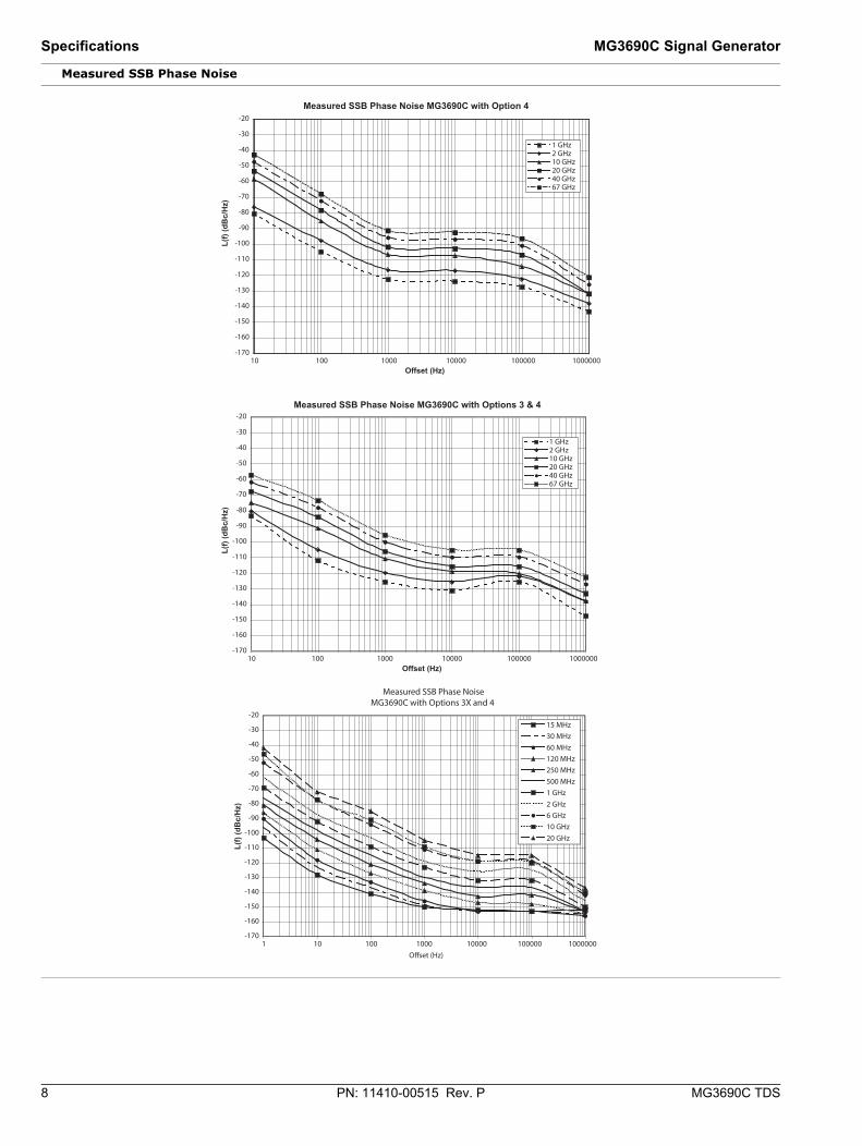
Measured SSB Phase Noise
Measured SSB Phase Noise MG3690C with Options 3 & 4
-170
-160
-150
-140
-130
-120
-110
-100
-90
-80
-70
-60
-50
-40
-30
-20
10 100 1000 10000 100000 1000000Offset (Hz)
L(f)
(dB
c/H
z)L(
f) (d
Bc/
Hz)
1 GHz2 GHz10 GHz20 GHz40 GHz67 GHz
Measured SSB Phase Noise MG3690C with Option 4
-170
-160
-150
-140
-130
-120
-110
-100
-90
-80
-70
-60
-50
-40
-30
-20
10 100 1000 10000 100000 1000000Offset (Hz)
1 GHz2 GHz10 GHz20 GHz40 GHz67 GHz
-170
-160
-150
-140
-130
-120
-110
-100
-90
-80
-70
-60
-50
-40
-30
-20
1 10 100 1000 10000 100000 1000000
15 MHz30 MHz60 MHz120 MHz250 MHz500 MHz1 GHz2 GHz6 GHz10 GHz20 GHz
Measured SSB Phase NoiseMG3690C with Options 3X and 4
Offset (Hz)
L(f)
(dB
c/H
z)

MG3690C Signal Generator Specifications
MG3690C TDS PN: 11410-00515 Rev. P 9
RF Output Power level specifications apply at 25 ± 10 ºC.
Maximum Leveled Output Power For output power with Option 22, 0.1 Hz to 10 MHz coverage, derate all specifications by 2 dB.
Maximum Leveled Output Power with Option 15 (High Power) Installed For output power with Option 22, 0.1 Hz to 10 MHz coverage, derate all specifications by 2 dB.
Model Number Configuration Frequency Range
(GHz) Output Power
(dBm)
Output Power with Step Attenuator
(dBm)
Output Power with Electronic Step
Attenuator (dBm)
MG3692C With opt 4 or 5 < 2a
a. ≤ 2.2 GHz with Option 4
+19 +18 Not Available STD ≥ 2b to ≤ 10
b. > 2.2 GHz with Option 4
+19 +18STD > 10 to ≤ 20 +17 +15
MG3694C
With opt 4 or 5 < 2a +15 +14
Not Available STD ≥ 2b to ≤ 10 +15 +14STD > 10 to ≤ 20 +12 +10STD > 20 to ≤ 40 +9 +6
MG3695C
With opt 4 or 5 < 2a +12 +10
Not Available STD ≥ 2b to ≤ 20 +10 +8STD > 20 to ≤ 40 +6 +3 STD > 40 to ≤ 50 +3 +0
MG3697C
With opt 4 or 5 < 2a +12 +10
Not Available STD ≥ 2b to ≤ 20 +10 +8STD > 20 to ≤ 40 +6 +3STD > 40 to ≤ 67 +3 +0c
c. Typical 60 GHz to 67 GHz
Model Number Configuration Frequency Range (GHz) Output Power
(dBm)
Output Power with Step Attenuator
(dBm)
Output Power with Electronic Step
Attenuator (dBm)
MG3692C
With opt 4 or 5
< 2a
a. ≤ 2.2 GHz with Option 4
+19 +18
Not Available
2b to 10
b. > 2.2 GHz with Option 4
+25 +24 > 10 to 16 +22 +20 > 16 to 20 +21 +19
Without opt 4 or 52 to 10 +26 +25
> 10 to 16 +25 +23 > 16 to 20 +23 +21
MG3694C With opt 4 or 5
< 2a +17 +16
Not Available ≥ 2b to ≤ 20 +21 +19> 20 to ≤ 40 +17 +15
Without opt 4 or 5 ≥ 2 to ≤ 20 +23 +21
> 20 to ≤ 40 +19 +17
MG3695C
With opt 4 or 5
< 2a +16 +14
Not Available
≥ 2b to ≤ 20 +21 +19> 20 to ≤ 40 +17 +15> 40 to ≤ 50 +11 +8
Without opt 4 or 5 ≥ 2 to ≤ 20 +23 +21
> 20 to ≤ 40 +19 +17> 40 to ≤ 50 +13 +10
MG3697C
With opt 4 or 5
< 2a +16 +15
Not Available
≥ 2b to ≤ 20 +19 +18> 20 to ≤ 40 +16 +14> 40 to ≤ 67 +9 +6c
c. Typical 60 GHz to 67 GHz
> 67 to ≤ 70 +3d
d. Typical
0d
Without opt 4 or 5
≥ 2 to ≤ 20 +21 +19> 20 to ≤ 40 +19 +16> 40 to ≤ 67 +9 +6c
> 67 to ≤ 70 +3d 0d

10 PN: 11410-00515 Rev. P MG3690C TDS
Specifications MG3690C Signal Generator
Minimum Settable Output Power Without an Attenuator –20 dBm
With an Attenuator –120 dBm
Minimum Leveled Output Power Without an Attenuator –15 dBm (–20 dBm, typical)
With an Attenuator –115 dBm (MG3692C and MG3694C)–105 dBm (MG3695C, and MG3697C)
Unleveled Output Power Range (typical)Without an Attenuator > 40 dB below max power
With an Attenuator > 130 dB below max power
Power Level Switching Time (To within specified accuracy)Without Change in Step Attenuator < 3 ms typical
With Change in Step Attenuator < 20 ms typicalWith Change in Electronic Step
Attenuator < 3 ms typicalPower level changes across –70 dB step will result in 20 ms delay.
Step Attenuator (Option 2) Adds a 10 dB/step attenuator110 dB range on models ≤ 40 GHz 90 dB range on models > 40 GHz
Accuracy and Flatness Flatness is included within the accuracy specification.Step Sweep and CW Modes
Analog Sweep Mode (Typical)
Attenuation Below Max Power
Frequency (GHz)≤ 40a,b
a. With high power Option 15, Accuracy and Flatness are ± 1.5 dB.b. Below 20 MHz, Accuracy and Flatness are ± 1.5 dB.
40 to 50 50 to 60 60 to 67Accuracy0 dB to 25 dB ± 1.0 dB ± 1.5 dB ± 1.5 dB ± 1.5 dB25 dB to 60 dB ± 1.0 dB ± 1.5 dB ± 3.5 dBc
c. Typical
N/A60 dB to 100 dB ± 1.0 dB ± 2.5 dBc ± 3.5 dBc N/AFlatness 0 dB to 25 dB ± 0.8 dB ± 1.1 dB ± 1.1 dB ± 1.1 dB25 dB to 60 dB ± 0.8 dB ± 1.1 dB ± 3.1 dBc N/A60 dB to 100 dB ± 0.8 dB ± 2.1 dBc ± 3.1 dBc N/A
Attenuation Below Max Power
Frequency (GHz)0.01 to 0.05 0.05 to 20 20 to 40 40 to 67
Accuracy0 dB to 12 dB ± 2.0 dB ± 2.0 dB ± 2.0 dB ± 3.0 dB12 dB to 30 dB ± 3.5 dB ± 3.5 dB ± 4.6 dB ± 5.6 dB30 dB to 60 dB ± 4.0 dB ± 4.0 dB ± 5.2 dB ± 6.2 dB60 dB to 122 dB ± 5.0 dB ± 5.0 dB ± 6.2 dB ± 7.2 dBFlatness0 dB to 12 dB ± 2.0 dB ± 2.0 dB ± 2.0 dB ± 2.5 dB12 dB to 30 dB ± 3.5 dB ± 3.5 dB ± 4.1 dB ± 5.1 dB30 dB to 60 dB ± 4.0 dB ± 4.0 dB ± 4.6 dB ± 5.6 dB60 dB to 122 dB ± 5.0 dB ± 5.0 dB ± 5.2 dB ± 6.2 dB
MG3690C Signal Generator Specifications
MG3690C TDS PN: 11410-00515 Rev. P 11
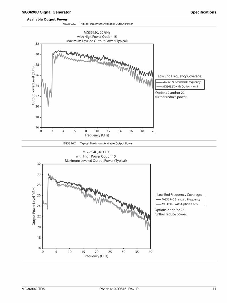
Available Output Power MG3692C Typical Maximum Available Output Power
MG3694C Typical Maximum Available Output Power
32
30
28
26
24
22
20
18
160 2 4 6 8 10 12 14 16 18 20
MG3692C, 20 GHzwith High Power Option 15
Maximum Leveled Output Power (Typical)
Out
put P
ower
Lev
el (d
Bm)
Frequency (GHz)
Low End Frequency Coverage:
MG3692C Standard FrequencyMG3692C with Option 4 or 5
Options 2 and/or 22 further reduce power.
32
30
28
26
24
22
20
18
160 5 10 15 20 25 30 35 40
MG3694C, 40 GHzwith High Power Option 15
Maximum Leveled Output Power (Typical)
Out
put P
ower
Lev
el (d
Bm)
Frequency (GHz)
Low End Frequency Coverage:
Options 2 and/or 22 further reduce power.
MG3694C Standard FrequencyMG3694C with Option 4 or 5
12 PN: 11410-00515 Rev. P MG3690C TDS
Specifications MG3690C Signal Generator
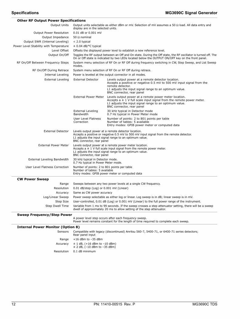
Other RF Output Power Specifications Output Units Output units selectable as either dBm or mV. Selection of mV assumes a 50 Ω load. All data entry and
display are in the selected units.Output Power Resolution 0.01 dB or 0.001 mV
Output Impedance 50 Ω nominalOutput SWR (Internal Leveling) < 2.0 typical
Power Level Stability with Temperature ± 0.04 dB/°C typicalLevel Offset Offsets the displayed power level to establish a new reference level.
Output On/Off Toggles the RF output between an Off and On state. During the Off state, the RF oscillator is turned off. The On or Off state is indicated by two LEDs located below the OUTPUT ON/OFF key on the front panel.
RF On/Off Between Frequency Steps System menu selection of RF On or RF Off during frequency switching in CW, Step Sweep, and List Sweep modes.
RF On/Off During Retrace System menu selection of RF On or RF Off during retrace.Internal Leveling Power is leveled at the output connector in all modes.
.
External Detector Levels output power at a remote detector location. Accepts a positive or negative 0.5 mV to 500 mV input signal from the remote detector. L1 adjusts the input signal range to an optimum value. BNC connector, rear panel
External Power Meter Levels output power at a remote power meter location. Accepts a ± 1 V full scale input signal from the remote power meter. L1 adjusts the input signal range to an optimum value. BNC connector, rear panel
External Leveling Bandwidth 30 kHz typical in Detector mode.0.7 Hz typical in Power Meter mode.
User Level Flatness Correction Number of points: 2 to 801 points per tableNumber of tables: 5 availableEntry modes: GPIB power meter or computed data
CW Power Sweep Range Sweeps between any two power levels at a single CW frequency.
Resolution 0.01 dB/step (Log) or 0.001 mV (Linear)Accuracy Same as CW power accuracy
Log/Linear Sweep Power sweep selectable as either log or linear. Log sweep is in dB; linear sweep is in mV.Step Size User-controlled, 0.01 dB (Log) or 0.001 mV (Linear) to the full power range of the instrument.
Step Dwell Time Variable from 1 ms to 99 seconds. If the sweep crosses a step attenuator setting, there will be a sweep dwell of approximately 20 ms to allow setting of the step attenuator.
Sweep Frequency/Step Power A power level step occurs after each frequency sweep. Power level remains constant for the length of time required to complete each sweep.
Internal Power Monitor (Option 8) Sensors Compatible with legacy (discontinued) Anritsu 560-7, 5400-71, or 6400-71 series detectors;
Rear panel inputRange +16 dBm to –35 dBm
Accuracy ± 1 dB, (+16 dBm to –10 dBm) ± 2 dB, (–10 dBm to –35 dBm)
Resolution 0.1 dB minimum
External Leveling External Detector Levels output power at a remote detector location. Accepts a positive or negative 0.5 mV to 500 mV input signal from the remote detector. L1 adjusts the input signal range to an optimum value. BNC connector, rear panel
External Power Meter Levels output power at a remote power meter location. Accepts a ± 1 V full scale input signal from the remote power meter. L1 adjusts the input signal range to an optimum value. BNC connector, rear panel
External Leveling Bandwidth
30 kHz typical in Detector mode0.7 Hz typical in Power Meter mode
User Level Flatness Correction
Number of points: 2 to 801 points per tableNumber of tables: 5 availableEntry modes: GPIB power meter or computed data
MG3690C Signal Generator Specifications
MG3690C TDS PN: 11410-00515 Rev. P 13
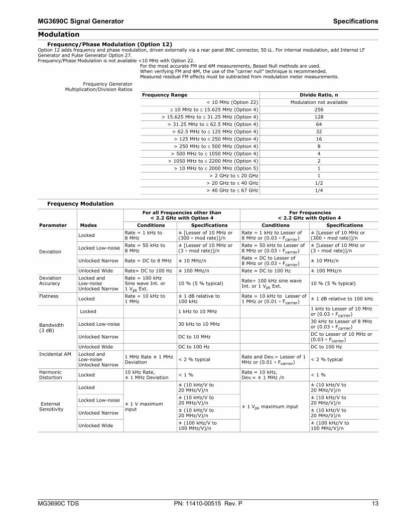
Modulation Frequency/Phase Modulation (Option 12)
Option 12 adds frequency and phase modulation, driven externally via a rear panel BNC connector, 50 Ω.. For internal modulation, add Internal LF Generator and Pulse Generator Option 27.Frequency/Phase Modulation is not available <10 MHz with Option 22.
For the most accurate FM and ΦM measurements, Bessel Null methods are used.When verifying FM and ΦM, the use of the “carrier null” technique is recommended. Measured residual FM effects must be subtracted from modulation meter measurements.
Frequency GeneratorMultiplication/Division Ratios
Frequency Modulation
Frequency Range Divide Ratio, n< 10 MHz (Option 22) Modulation not available
≥ 10 MHz to ≤ 15.625 MHz (Option 4) 256> 15.625 MHz to ≤ 31.25 MHz (Option 4) 128
> 31.25 MHz to ≤ 62.5 MHz (Option 4) 64> 62.5 MHz to ≤ 125 MHz (Option 4) 32> 125 MHz to ≤ 250 MHz (Option 4) 16> 250 MHz to ≤ 500 MHz (Option 4) 8
> 500 MHz to ≤ 1050 MHz (Option 4) 4> 1050 MHz to ≤ 2200 MHz (Option 4) 2
> 10 MHz to ≤ 2000 MHz (Option 5) 1> 2 GHz to ≤ 20 GHz 1
> 20 GHz to ≤ 40 GHz 1/2> 40 GHz to ≤ 67 GHz 1/4
Parameter Modes
For all Frequencies other than < 2.2 GHz with Option 4
For Frequencies < 2.2 GHz with Option 4
Conditions Specifications Conditions Specifications
Deviation
Locked Rate = 1 kHz to 8 MHz
± [Lesser of 10 MHz or(300 ∗ mod rate)]/n
Rate = 1 kHz to Lesser of 8 MHz or (0.03 ∗ Fcarrier)
± [Lesser of 10 MHz or(300 ∗ mod rate)]/n
Locked Low-noise Rate = 50 kHz to 8 MHz
± [Lesser of 10 MHz or(3 ∗ mod rate)]/n
Rate = 50 kHz to Lesser of 8 MHz or (0.03 ∗ Fcarrier)
± [Lesser of 10 MHz or(3 ∗ mod rate)]/n
Unlocked Narrow Rate = DC to 8 MHz ± 10 MHz/n Rate = DC to Lesser of 8 MHz or (0.03 ∗ Fcarrier)
± 10 MHz/n
Unlocked Wide Rate= DC to 100 Hz ± 100 MHz/n Rate = DC to 100 Hz ± 100 MHz/n Deviation Accuracy
Locked and Low-noise Unlocked Narrow
Rate = 100 kHz Sine wave Int. or 1 Vpk Ext.
10 % (5 % typical) Rate= 100 kHz sine wave Int. or 1 Vpk Ext. 10 % (5 % typical)
Flatness Locked Rate = 10 kHz to 1 MHz
± 1 dB relative to 100 kHz
Rate = 10 kHz to Lesser of 1 MHz or (0.01 ∗ Fcarrier)
± 1 dB relative to 100 kHz
Bandwidth (3 dB)
Locked 1 kHz to 10 MHz 1 kHz to Lesser of 10 MHz or (0.03 ∗ Fcarrier)
Locked Low-noise 30 kHz to 10 MHz 30 kHz to Lesser of 8 MHz or (0.03 ∗ Fcarrier)
Unlocked Narrow DC to 10 MHz DC to Lesser of 10 MHz or (0.03 ∗ Fcarrier)
Unlocked Wide DC to 100 Hz DC to 100 Hz Incidental AM Locked and
Low-noise Unlocked Narrow
1 MHz Rate ± 1 MHz Deviation < 2 % typical Rate and Dev.= Lesser of 1
MHz or (0.01 ∗ Fcarrier) < 2 % typical
Harmonic Distortion Locked 10 kHz Rate,
± 1 MHz Deviation < 1 % Rate = 10 kHz, Dev.= ± 1 MHz /n < 1 %
External Sensitivity
Locked
± 1 V maximum input
± (10 kHz/V to 20 MHz/V)/n
± 1 Vpk maximum input
± (10 kHz/V to 20 MHz/V)/n
Locked Low-noise ± (10 kHz/V to 20 MHz/V)/n
± (10 kHz/V to 20 MHz/V)/n
Unlocked Narrow ± (10 kHz/V to 20 MHz/V)/n
± (10 kHz/V to 20 MHz/V)/n
Unlocked Wide ± (100 kHz/V to 100 MHz/V)/n
± (100 kHz/V to 100 MHz/V)/n
14 PN: 11410-00515 Rev. P MG3690C TDS
Specifications MG3690C Signal Generator
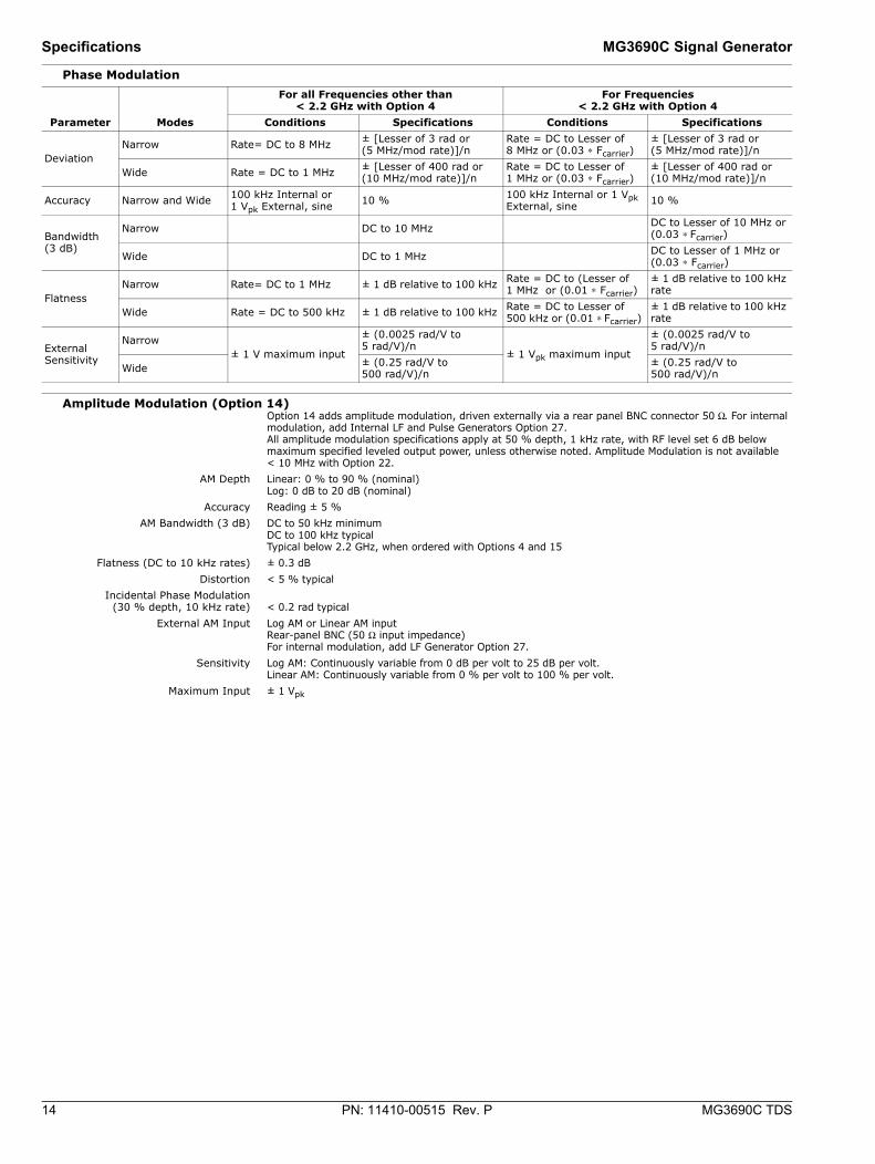
Phase Modulation
Amplitude Modulation (Option 14) Option 14 adds amplitude modulation, driven externally via a rear panel BNC connector 50 Ω. For internal modulation, add Internal LF and Pulse Generators Option 27.All amplitude modulation specifications apply at 50 % depth, 1 kHz rate, with RF level set 6 dB below maximum specified leveled output power, unless otherwise noted. Amplitude Modulation is not available < 10 MHz with Option 22.
AM Depth Linear: 0 % to 90 % (nominal)Log: 0 dB to 20 dB (nominal)
Accuracy Reading ± 5 %AM Bandwidth (3 dB) DC to 50 kHz minimum
DC to 100 kHz typicalTypical below 2.2 GHz, when ordered with Options 4 and 15
Flatness (DC to 10 kHz rates) ± 0.3 dBDistortion < 5 % typical
Incidental Phase Modulation(30 % depth, 10 kHz rate) < 0.2 rad typical
External AM Input Log AM or Linear AM inputRear-panel BNC (50 Ω input impedance)For internal modulation, add LF Generator Option 27.
Sensitivity Log AM: Continuously variable from 0 dB per volt to 25 dB per volt.Linear AM: Continuously variable from 0 % per volt to 100 % per volt.
Maximum Input ± 1 Vpk
Parameter Modes
For all Frequencies other than< 2.2 GHz with Option 4
For Frequencies< 2.2 GHz with Option 4
Conditions Specifications Conditions Specifications
Deviation Narrow Rate= DC to 8 MHz ± [Lesser of 3 rad or
(5 MHz/mod rate)]/n Rate = DC to Lesser of 8 MHz or (0.03 ∗ Fcarrier)
± [Lesser of 3 rad or(5 MHz/mod rate)]/n
Wide Rate = DC to 1 MHz ± [Lesser of 400 rad or (10 MHz/mod rate)]/n
Rate = DC to Lesser of 1 MHz or (0.03 ∗ Fcarrier)
± [Lesser of 400 rad or(10 MHz/mod rate)]/n
Accuracy Narrow and Wide 100 kHz Internal or 1 Vpk External, sine 10 % 100 kHz Internal or 1 Vpk
External, sine 10 %
Bandwidth (3 dB)
Narrow DC to 10 MHz DC to Lesser of 10 MHz or (0.03 ∗ Fcarrier)
Wide DC to 1 MHz DC to Lesser of 1 MHz or (0.03 ∗ Fcarrier)
Flatness Narrow Rate= DC to 1 MHz ± 1 dB relative to 100 kHz Rate = DC to (Lesser of
1 MHz or (0.01 ∗ Fcarrier) ± 1 dB relative to 100 kHz rate
Wide Rate = DC to 500 kHz ± 1 dB relative to 100 kHz Rate = DC to Lesser of 500 kHz or (0.01 ∗ Fcarrier)
± 1 dB relative to 100 kHz rate
External Sensitivity
Narrow ± 1 V maximum input
± (0.0025 rad/V to 5 rad/V)/n
± 1 Vpk maximum input
± (0.0025 rad/V to 5 rad/V)/n
Wide ± (0.25 rad/V to 500 rad/V)/n
± (0.25 rad/V to 500 rad/V)/n
MG3690C Signal Generator Specifications
MG3690C TDS PN: 11410-00515 Rev. P 15
Pulse Modulation (Option 26) Option 26 adds pulse modulation, driven externally via a rear panel BNC connector, TTL. For internal modulation, add Internal LF and Pulse Generators Option 27.Pulse modulation specifications apply at maximum rated power, unless otherwise noted. Pulse modulation is not available < 10 MHz with Option 22.
On/Off Ratio > 80 dB or> 70 dB with high power Option 15;> 70 dB with Option 4 or 5 and without Option 2 at 500 MHz
Minimum Leveled Pulse Width 100 ns, ≥ 1 GHz1 μs, < 1 GHz
Minimum Unleveled Pulse Width < 10 nsLevel Accuracy Relative to CW
(100 Hz to 1 MHz PRF) ± 0.5 dB, ≥ 1 μs pulse width± 1.0 dB, < 1 μs pulse width
Pulse Delay (typical) 50 ns in External ModePRF Range DC to 10 MHz, unleveled
100 Hz to 5 MHz, leveledExternal Input Rear-panel BNC
For internal modulation, add Pulse Generator Option 27.Drive Level TTL compatible inputInput Logic Positive-true or negative-true, selectable from modulation menu
Internal LF and Pulse Generators (Option 27) An internal pulse generator and two internal waveform generators are added, one providing a frequency or phase modulating signal and the other an amplitude modulating signal. This Internal LF and Pulse Generators option can only be ordered in combination with either FM/ΦM, AM, or Pulse options, 12, 14, and 26 respectively.
Waveforms Sinusoid, square-wave, triangle, positive ramp, negative ramp, Gaussian noise, uniform noise(Check Option 10 for User-defined.)
Rate 0.1 Hz to 10 MHz sinusoidal0.1 Hz to 1 MHz square-wave, triangle, ramps
Resolution 0.1 HzAccuracy Same as instrument timebase ± 0.014 Hz
Waveform Outputs Two BNC connectors on the rear panel, FM/ΦM OUT and AM OUTPulse Modes Singlet, doublet, triplet, quadruplet
Pulse Triggers Free-run, triggered, gated, delayed, triggered with delay, swept-delayPulse Inputs/Outputs Video pulse and sync out, rear-panel BNC connectors
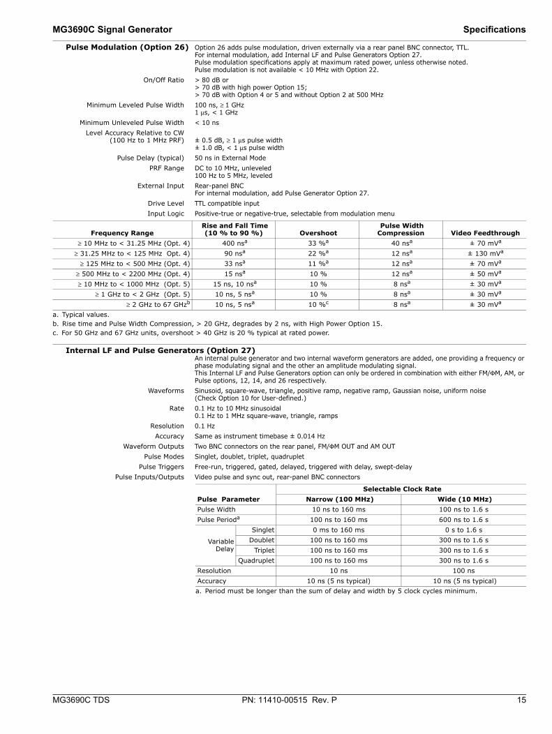
Frequency Range Rise and Fall Time
(10 % to 90 %) Overshoot Pulse Width Compression Video Feedthrough
≥ 10 MHz to < 31.25 MHz (Opt. 4) 400 nsa
a. Typical values.
33 %a 40 nsa ± 70 mVa
≥ 31.25 MHz to < 125 MHz Opt. 4) 90 nsa 22 %a 12 nsa ± 130 mVa
≥ 125 MHz to < 500 MHz (Opt. 4) 33 nsa 11 %a 12 nsa ± 70 mVa
≥ 500 MHz to < 2200 MHz (Opt. 4) 15 nsa 10 % 12 nsa ± 50 mVa
≥ 10 MHz to < 1000 MHz (Opt. 5) 15 ns, 10 nsa 10 % 8 nsa ± 30 mVa
≥ 1 GHz to < 2 GHz (Opt. 5) 10 ns, 5 nsa 10 % 8 nsa ± 30 mVa
≥ 2 GHz to 67 GHzb
b. Rise time and Pulse Width Compression, > 20 GHz, degrades by 2 ns, with High Power Option 15.
10 ns, 5 nsa 10 %c
c. For 50 GHz and 67 GHz units, overshoot > 40 GHz is 20 % typical at rated power.
8 nsa ± 30 mVa
Pulse Parameter Selectable Clock Rate
Narrow (100 MHz) Wide (10 MHz) Pulse Width 10 ns to 160 ms 100 ns to 1.6 s Pulse Perioda
a. Period must be longer than the sum of delay and width by 5 clock cycles minimum.
100 ns to 160 ms 600 ns to 1.6 s
VariableDelay
Singlet 0 ms to 160 ms 0 s to 1.6 s Doublet 100 ns to 160 ms 300 ns to 1.6 s
Triplet 100 ns to 160 ms 300 ns to 1.6 s Quadruplet 100 ns to 160 ms 300 ns to 1.6 s
Resolution 10 ns 100 ns Accuracy 10 ns (5 ns typical) 10 ns (5 ns typical)
16 PN: 11410-00515 Rev. P MG3690C TDS
Specifications MG3690C Signal Generator
Ultra-Stable Phase Tracking (Option 36) Option 36 enables up to three MG3690C units fitted with Option 3 or 3X to phase track with a very high degree of stability. Option 36 provides additional rear panel connectors to link internal reference signals together.
100 MHz Reference Output Provides the reference signal to drive up to two other MG3690C generators. All MG3690C generators must have Option 36 and either Option 3 or 3X. This signal is only intended for use with other Option 36 instruments.
100 MHz Reference Input Accepts the 100 MHz reference signal from another MG3690C fitted with Option 36. This input is only intended for use with other Option 36 instruments.
Phase Drift < ± 1° over 5 seconds (typical)< ± 1.5° over 100 seconds (typical), after 24 hours warm-up time
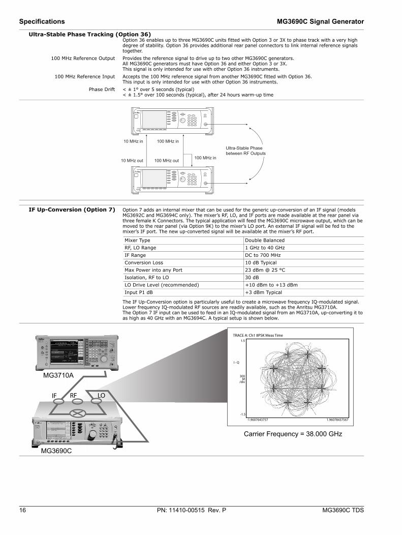
IF Up-Conversion (Option 7) Option 7 adds an internal mixer that can be used for the generic up-conversion of an IF signal (models MG3692C and MG3694C only). The mixer’s RF, LO, and IF ports are made available at the rear panel via three female K Connectors. The typical application will feed the MG3690C microwave output, which can be moved to the rear panel (via Option 9K) to the mixer’s LO port. An external IF signal will be fed to the mixer’s IF port. The new up-converted signal will be available at the mixer’s RF port.
The IF Up-Conversion option is particularly useful to create a microwave frequency IQ-modulated signal. Lower frequency IQ-modulated RF sources are readily available, such as the Anritsu MG3710A. The Option 7 IF input can be used to feed in an IQ-modulated signal from an MG3710A, up-converting it to as high as 40 GHz with an MG3694C. A typical setup is shown below.
Mixer Type Double Balanced RF, LO Range 1 GHz to 40 GHz IF Range DC to 700 MHz Conversion Loss 10 dB Typical Max Power into any Port 23 dBm @ 25 °C Isolation, RF to LO 30 dB LO Drive Level (recommended) +10 dBm to +13 dBm Input P1 dB +3 dBm Typical
10 MHz out
10 MHz in
100 MHz out
100 MHz in
100 MHz in
Ultra-Stablebetween RF Outputs
Phase
TRACE A: Ch1 8PSK Meas Time1.5
-1.5
-1.9607643757 1.96078437567
I - Q
300M
/div
MG3710A
MG3690C
Carrier Frequency = 38.000 GHz
RFIF LO
MG3690C Signal Generator Specifications
MG3690C TDS PN: 11410-00515 Rev. P 17
User-Defined Modulation Waveform Software (Option 10) An external software package provides the ability to download user-defined waveforms into the internal LF Generator’s memory (requires Option 27, 28A, or 28B). The MG3690C provides as standard with the LF Generator sinusoidal, square-wave, triangle, positive ramp, Gaussian noise, and uniform noise waveforms.
Two look-up tables of 65,536 points can be used to generate two pseudo-random waveforms, one for amplitude modulation and the other for frequency or phase modulation. The download files are simple space-delimited text files containing integer numbers between 0 and 4095, where 0 corresponds to the minimum modulation level and 4095 the maximum.
In addition to the capability of downloading custom waveforms, the software offers a virtual instrument modulation panel. Custom modulation setups with user waveforms can be stored for future use. For IFF signal simulation, the internal generators can be synchronized. They can also be disconnected from the internal modulators, making the low frequency waveforms available at the rear panel for external purposes.
Scan Modulation (Option 20) Option 20 adds a microwave linearly controlled attenuator to provide deep AM capability. This modulator is inserted outside the leveling loop but before the optional step attenuator. It is switched in and out of the RF path. Scan modulation is driven externally only.
One application of this feature is storing an antenna pattern wave form in memory and using it to feed the external input to the scan modulator, Option 20.
Frequency Range 2 GHz to 18 GHz Attenuation Range 0 dB to 60 dB Flatness/Accuracy ± 1.5 dB/± 1.5 dB, 0 dB to 40 dB
± 3 dB/± 2 dB, 40 dB to 60 dB Step Response < 1 μs
Sensitivity –10 dB/V Modulation Bandwidth1 20 kHz (small signal)
5 kHz (large signal) Insertion Loss < 6 dB (when engaged)
Input Rear Panel BNC connector High Impedance
1. Small and Large Signal Bandwidth is defined as the frequency at which the modulation depth decreases by 50% as measured with a square-law detector under the following conditions:Small Signal: A modulation frequency of 100 Hz and a modulation depth of ±3 dB at a quiescent level of -6 dB.Large Signal: A modulation frequency of 100 Hz and a 100% modulation depth at a quiescent level of -6 dB.
18 PN: 11410-00515 Rev. P MG3690C TDS
Specifications MG3690C Signal Generator
Millimeter-wave Frequency Coverage Millimeter-Wave Multiplier 2000-1694 Series
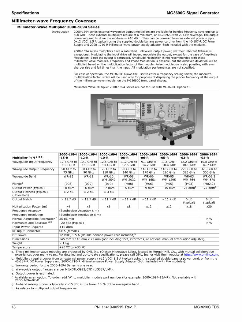
Introduction 2000-1694 series external waveguide output multipliers are available for banded frequency coverage up to 500 GHz. These external multipliers require at a minimum, an MG3692C with 20 GHz coverage. The output power required to drive the modules is +10 dBm. They can be powered from an external power supply (+12 VDC, 1.5 A typical) using the supplied double banana power cord, or from the 40-187-R DC Power Supply and 2000-1710-R Millimeter-wave power supply adapter. Both included with the modules.
2000-1694 series multipliers have a saturated, unleveled, output power, yet their inherent flatness is exceptional. Modulating the input drive will indeed modulate the output, except for the case of Amplitude Modulation. Since the output is saturated, Amplitude Modulation is not recommended with these millimeter-wave modules. Frequency and Phase Modulation is possible, but the achieved deviation will be multiplied based on the multiplication factor of the module. Pulse modulation is also possible, with even sharper rise and fall times than the input. All modulation performances are not specified.
For ease of operation, the MG3690C allows the user to enter a frequency scaling factor, the module's multiplication factor, which will be used only for purposes of displaying the proper frequency at the output of the millimeter-wave module, on the MG3690C front panel display.
Millimeter-Wave Multiplier 2000-1694 Series are not for use with MG3690C Option 18.
Multiplier P/N a b c
a. These millimeter-wave modules are produced by OML Inc. (Oleson Microwave Labs), located in Morgan Hill, CA., with mutual collaborative experiences over many years. For detailed and up-to-date specifications, please call OML, Inc. or visit their website at http://www.omlinc.com.
b. Multipliers require power from an external power supply (+12 VDC, 1.5 A typical) using the supplied double banana power cord, or from the 40-187-R DC Power Supply and 2000-1710-R Millimeter-wave Power Supply Adapter (both included with the modules).
c. Warranty period for the 2000-1694 Series is one year.
2000-1694-15-R
2000-1694-12-R
2000-1694-10-R
2000-1694-08-R
2000-1694-06-R
2000-1694-05-R
2000-1694-03-R
2000-1694-02-R
Waveguide Input Frequency 12.5 GHz to 18.8 GHz
10.0 GHz to 15.0 GHz
12.5 GHz to 18.4 GHz
11.2 GHz to 17.5 GHz
9.1 GHz to 14.2 GHz
11.6 GHz - 18.4 GHz
12.2 GHz to 18.1 GHz
10.8 GHz to 16.7 GHz
Waveguide Output Frequency 50 GHz to 75 GHz
60 GHz to 90 GHz
75 GHz to 110 GHz
90 GHz to 140 GHz
110 GHz to 170 GHz
140 GHz to 220 GHz
220 GHz to 325 GHz
325 GHz to 500 GHz
Waveguide Band WR-15 WR-12 WR-10 WM-2540
WR-08 WM-2032
WR-06 WM-1651
WR-05 WM-1295
WR-03 WM-864
WR-02.2 WM-570
Flanged
d. Waveguide output flanges are per MIL-DTL-3922/67D (UG387/U-M).
(008) (009) (010) (M08) (M06) (M05) (M03) (M02.2)Output Power (typical) +8 dBm +6 dBm +7 dBm –5 dBm –9 dBm –15 dBm –25 dBme
e. Output power is estimated.
–27 dBme
Output Flatness (typical) (Unleveled)
± 2 dB ± 2 dB ± 3 dB — — — — —
Output Match > 11.7 dB > 11.7 dB > 11.7 dB > 11.7 dB > 11.7 dB > 11.7 dB 6 dB (typical)
6 dB (typical)
Multiplication Factor (m) x4 x6 x6 x8 x12 x12 x18 x30Frequency Accuracy (Synthesizer Accuracy x m) Frequency Resolution (Synthesizer Resolution x m) Manual Adjustable Attenuator f
f. Available as an option. To order, add "A" to multiplier module part number (for example, 2000-1694-15A-R). Not available with 2000-1694-02-R.
25 dB min N/AHarmonics and Spurious g,h
g. In-band mixing products typically ≤ –15 dBc in the lower 10 % of the waveguide band.h. As relates to multiplied output frequencies.
–20 dBc (typical) N/AInput Power Required +10 dBm RF Input Connector SMA (female) DC Power 12 VDC, 1.5 A (double-banana power cord included)b
Dimensions 145 mm x 110 mm x 72 mm (not including feet, interfaces, or optional manual attenuation adjuster) Weight < 1 kg Temperature +20 ºC to +30 ºC

MG3690C Signal Generator Specifications
MG3690C TDS PN: 11410-00515 Rev. P 19
Inputs and Outputs Refer to the illustration on page 20.Connectors may be available but not active if option is not ordered.Options (7 & 18), (7 & 20), (8 & 9) are mutually exclusive, as they share the same rear panel space.
EXT ALC IN Provides for leveling the RF output signal externally with either a detector or power meter. Signal requirements are shown in the RF Output specifications. BNC type, rear panel
RF OUTPUT (Option 9) Provides for RF output from 50 Ω source impedance. Option 9 moves the RF Output connector from the front to the rear panel. Note: Option 9 and Option 8 are mutually exclusive, as they share the same rear panel space.K Connector (female) fmax ≤ 40 GHz V Connector (female) fmax ≥ 40 GHz
10 MHz REF IN Accepts an external 10 MHz ± 50 Hz, 0 dBm to +20 dBm time-base signal. Automatically disconnects the internal high-stability time-base option, if installed. 50 Ω impedanceBNC type, rear panel
10 MHz REF OUT Provides a 1 Vp-p, AC coupled, 10 MHz signal derived from the internal frequency standard. 50 Ω impedanceBNC type, rear panel
100 MHz REF IN (Option 36) Accepts the 100 MHz signal from an MG3690C with Option 36 for ultra-stable phase tracking.100 MHz REF OUT (Option 36) Provides the 100 MHz signal for an MG3690C with Option 36 ultra-stable phase tracking.
HORIZ OUT (Horizontal Sweep Output) Provides 0 V at beginning and +10 V at end of sweep, regardless of sweep width. In CW mode, the voltage is proportional to frequency between 0 V at low end and +10 V at the high end of the range. In CW mode, if CW RAMP is enabled, a repetitive, 0 V to +10 V ramp is provided. BNC type, rear panel
EFC IN Provides the capability to frequency modulate the internal crystal oscillator, allowing phase locking of the synthesizer inside an external lock loop. Specifications are on page 2. BNC type, rear panel
AUX I/O (Auxiliary Input/Output) Provides for most of the rear panel BNC connections through a single, 25-pin, D type connector. Supports master-slave operation with another synthesizer or allows for a single-cable interface with the Model 56100A Scalar Network Analyzer and other Anritsu instruments. See Aux I/O Pin Descriptions on page 20. Also provides an Ethernet factory default IP address reset function via pin 19.25 pin D-type, rear panel
SERIAL I/O Provides access to RS-232 terminal ports to support service and calibration functions and master-slave operations. RJ45 type, rear panel
ETHERNET (10/100 Base-T LAN) I/O Provides input/output connections for an Ethernet interface.RJ45 type, rear panel
IEEE-488 GPIB Provides input/output connections for the General Purpose Interface Bus (GPIB). Type 57, rear panel
DC OUT (Option 18) Supplies +15 VDC, 1 A (nominal)Note: Option 18 and Option 7 are mutually exclusive, as they share the same rear panel space.
RF, LO, IF (Option 7) Provides access to an internal IF up-conversion mixer. Note: Option 7 and 18, as well as Option 7 and 20 are mutually exclusive, as they share the same rear panel space.K Connector (female, 3 each), rear panel
PULSE TRIG IN (Option 26) Accepts an external TTL compatible signal to pulse modulate the RF output signal or to trigger or to gate the optional internal pulse generator.BNC type, rear panel
PULSE SYNC OUT (Option 27) Provides a TTL compatible signal, synchronized to the internal pulse modulation output. BNC type, rear panel
PULSE VIDEO OUT (Option 27) Provides a video modulating signal from the internal pulse generator. BNC type, rear panel
AM IN (Option 14) Accepts an external signal to amplitude modulate the RF output signal.50 Ω impedanceBNC type, rear panel
FM/ΦM IN (Option 12) Accepts an external signal to frequency or phase modulate the RF output signal. 50 Ω impedanceBNC type, rear panel
AM OUT (Option 27) Provides the amplitude modulation waveform from the internal LF generator. BNC type, rear panel.FM/ΦM OUT (Option 27) Provides the frequency or phase modulation waveform from the internal LF generator.
BNC type, rear panelSCAN MOD IN (Option 20) Accepts an external signal to scan modulate the RF output signal.
Note: Option 20 and Option 7 are mutually exclusive, as they share the same rear panel space.High ImpedanceBNC type, rear panel
POWER MONITOR IN (Option 8) Accepts an external detector for power monitoring. Custom type, rear panelNote: Options 8 and 9 are mutually exclusive, as they share the same rear panel space.
20 PN: 11410-00515 Rev. P MG3690C TDS
Specifications MG3690C Signal Generator
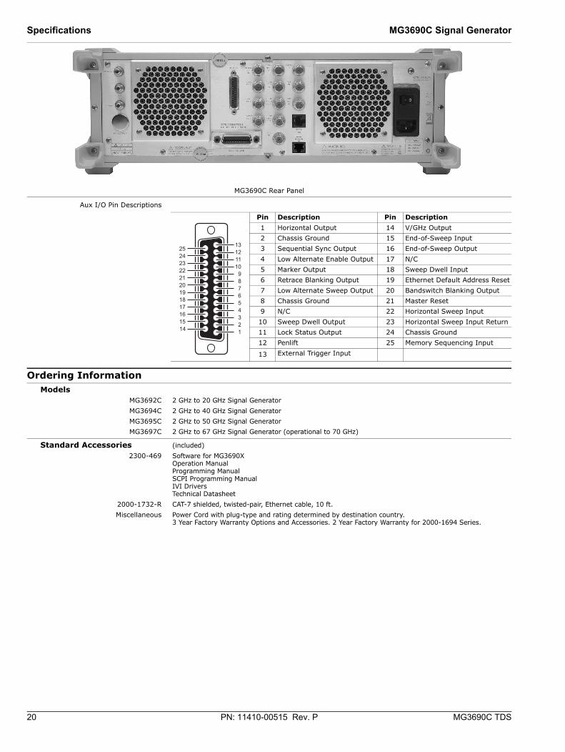
Aux I/O Pin Descriptions
Ordering Information Models
MG3692C 2 GHz to 20 GHz Signal GeneratorMG3694C 2 GHz to 40 GHz Signal GeneratorMG3695C 2 GHz to 50 GHz Signal GeneratorMG3697C 2 GHz to 67 GHz Signal Generator (operational to 70 GHz)
Standard Accessories (included)2300-469 Software for MG3690X
Operation ManualProgramming ManualSCPI Programming ManualIVI DriversTechnical Datasheet
2000-1732-R CAT-7 shielded, twisted-pair, Ethernet cable, 10 ft.Miscellaneous Power Cord with plug-type and rating determined by destination country.
3 Year Factory Warranty Options and Accessories. 2 Year Factory Warranty for 2000-1694 Series.
MG3690C Rear Panel
Pin Description Pin Description1 Horizontal Output 14 V/GHz Output2 Chassis Ground 15 End-of-Sweep Input3 Sequential Sync Output 16 End-of-Sweep Output4 Low Alternate Enable Output 17 N/C5 Marker Output 18 Sweep Dwell Input6 Retrace Blanking Output 19 Ethernet Default Address Reset7 Low Alternate Sweep Output 20 Bandswitch Blanking Output8 Chassis Ground 21 Master Reset9 N/C 22 Horizontal Sweep Input10 Sweep Dwell Output 23 Horizontal Sweep Input Return11 Lock Status Output 24 Chassis Ground12 Penlift 25 Memory Sequencing Input
13 External Trigger Input
10111213
252423222120191817161514
987654321
MG3690C Signal Generator Specifications
MG3690C TDS PN: 11410-00515 Rev. P 21
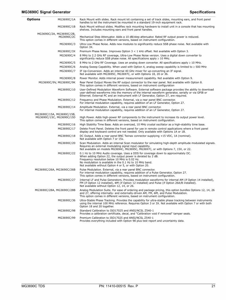
Options MG3690C/1A Rack Mount with slides. Rack mount kit containing a set of track slides, mounting ears, and front panel handles to let the instrument be mounted in a standard 19-inch equipment rack.
MG3690C/1B Rack Mount without slides. Modifies rack mounting hardware to install unit in a console that has mounting shelves. Includes mounting ears and front panel handles.
MG3690C/2A, MG3690C/2B,MG3690C/2C Mechanical Step Attenuator. Adds a 10 dB/step attenuator. Rated RF output power is reduced.
This option comes in different versions, based on instrument configuration.MG3690C/3 Ultra Low Phase Noise. Adds new modules to significantly reduce SSB phase noise. Not available with
Option 3X.MG3690C/3X Premium Phase Noise. Improves Option 3 < 1 kHz offset. Not available with Option 3.MG3690C/4 8 MHz to 2.2 GHz RF coverage, Ultra-Low Phase Noise version. Uses a digital down converter to
significantly reduce SSB phase noise. All specifications apply ≥ 10 MHz.MG3690C/5 8 MHz to 2 GHz RF Coverage. Uses an analog down converter. All specifications apply ≥ 10 MHz.MG3690C/6 Analog Sweep Capability. When used with Option 4, analog sweep capability is limited to ≥ 500 MHzMG3690C/7 IF Up-Conversion. Adds an internal 40 GHz mixer for up-converting an IF signal.
Not available with MG3695C, MG3697C, or with Options 18, 20 or 36.MG3690C/8 Power Monitor. Adds internal power measurement capability. Not available with Option 9.
MG3690C/9V, MG3690C/9K Rear Panel Output Moves the RF output connector to the rear panel. Not available with Option 8.This option comes in different versions, based on instrument configuration
MG3690C/10 User-Defined Modulation Waveform Software. External software package provides the ability to download user-defined waveforms into the memory of the internal waveform generator, serially or via GPIB or Ethernet. External PC and an instrument with LF Generator, Option 27, are required.
MG3690C/12 Frequency and Phase Modulation. External, via a rear panel BNC connector.For internal modulation capability, requires addition of an LF Generator, Option 27.
MG3690C/14 Amplitude Modulation. External, via a rear panel BNC connector. For internal modulation capability, requires addition of an LF Generator, Option 27.
MG3690C/15A, MG3690C/15B,MG3690C/15C, MG3690C/15D High Power. Adds high-power RF components to the instrument to increase its output power level.
This option comes in different versions, based on instrument configuration.MG3690C/16 High Stability Time Base. Adds an ovenized, 10 MHz crystal oscillator as a high-stability time base.MG3690C/17 Delete Front Panel. Deletes the front panel for use in remote control applications where a front panel
display and keyboard control are not needed. Only available with Options 1A or 1B.MG3690C/18 DC Output. Adds a rear panel BNC Twinax connector supplying +15 VDC, 1A (nominal).
Not available with Option 7 or 15x.MG3690C/20 Scan Modulation. Adds an internal Scan modulator for simulating high-depth amplitude modulated signals.
Requires an external modulating signal input capability.Not available on models MG3694C, MG3695C, MG3697C, or with Options 7, 15X, or 22.
MG3690C/22 0.1 Hz to 10 MHz Audio coverage. Uses a DDS for coverage down to approximately DC.When adding Option 22, the output power is derated by 2 dB.Frequency resolution below 10 MHz is 0.02 Hz.No modulation is available in the 0.1 Hz to 10 MHz band. Not available without Option 4 or 5, or with Option 20.
MG3690C/26A, MG3690C/26B Pulse Modulation. External, via a rear panel BNC connector.For internal modulation capability, requires addition of a Pulse Generator, Option 27. This option comes in different versions, based on instrument configuration.
MG3690C/27 Internal LF and Pulse Generators. Provides modulation waveforms for internal AM (if Option 14 installed), FM (if Option 12 installed), ΦM (if Option 12 installed) and Pulse (if Option 26A/B installed). Not available without Option 12, 14, or 26.
MG3690C/28A, MG3690C/28B Analog Modulation Suite. For ease of ordering and package pricing, this option bundles Options 12, 14, 26 and 27, offering internally- and externally-driven AM, FM, ΦM, and Pulse Modulation. This option comes in different versions, based on instrument configuration.
MG3690C/36 Ultra-Stable Phase Tracking. Provides the capability for ultra-stable phase tracking between instruments using the internal 100 MHz reference. Requires Option 3 or 3X. Not available with Option 7 or with both Option 18 and 20 together.
MG3690C/98 Standard Calibration to ISO17025 and ANSI/NCSL Z540-1Provides a calibration certificate, decal, and "Calibration void if removed" tamper seals.
MG3690C/99 Premium Calibration to ISO17025 and ANSI/NCSL Z540-1Provides everything included with Option 98 plus test report and uncertainty data.
22 PN: 11410-00515 Rev. P MG3690C TDS
Specifications MG3690C Signal Generator
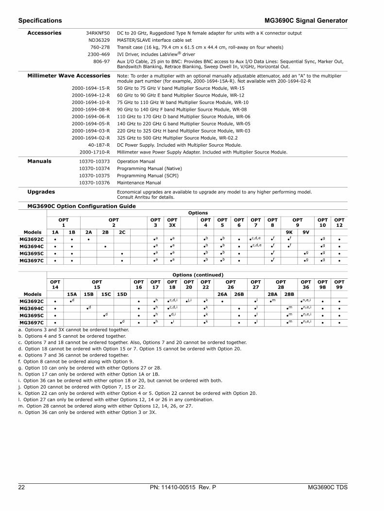
Accessories 34RKNF50 DC to 20 GHz, Ruggedized Type N female adapter for units with a K connector outputND36329 MASTER/SLAVE interface cable set760-278 Transit case (16 kg, 79.4 cm x 61.5 cm x 44.4 cm, roll-away on four wheels)
2300-469 IVI Driver, includes LabView® driver806-97 Aux I/O Cable, 25 pin to BNC: Provides BNC access to Aux I/O Data Lines: Sequential Sync, Marker Out,
Bandswitch Blanking, Retrace Blanking, Sweep Dwell In, V/GHz, Horizontal Out.
Millimeter Wave Accessories Note: To order a multiplier with an optional manually adjustable attenuator, add an "A" to the multiplier module part number (for example, 2000-1694-15A-R). Not available with 200-1694-02-R
2000-1694-15-R 50 GHz to 75 GHz V band Multiplier Source Module, WR-152000-1694-12-R 60 GHz to 90 GHz E band Multiplier Source Module, WR-122000-1694-10-R 75 GHz to 110 GHz W band Multiplier Source Module, WR-102000-1694-08-R 90 GHz to 140 GHz F band Multiplier Source Module, WR-082000-1694-06-R 110 GHz to 170 GHz D band Multiplier Source Module, WR-062000-1694-05-R 140 GHz to 220 GHz G band Multiplier Source Module, WR-052000-1694-03-R 220 GHz to 325 GHz H band Multiplier Source Module, WR-032000-1694-02-R 325 GHz to 500 GHz Multiplier Source Module, WR-02.2
40-187-R DC Power Supply. Included with Multiplier Source Module.2000-1710-R Millimeter wave Power Supply Adapter. Included with Multiplier Source Module.
Manuals 10370-10373 Operation Manual 10370-10374 Programming Manual (Native) 10370-10375 Programming Manual (SCPI) 10370-10376 Maintenance Manual
Upgrades Economical upgrades are available to upgrade any model to any higher performing model. Consult Anritsu for details.
MG3690C Option Configuration Guide
Models
Options OPT
1 OPT
2 OPT
3 OPT 3X
OPT 4
OPT 5
OPT 6
OPT 7
OPT 8
OPT9
OPT 10
OPT 12
1A 1B 2A 2B 2C 9K 9V MG3692C • • • •a
a. Options 3 and 3X cannot be ordered together.
•a •b
b. Options 4 and 5 cannot be ordered together.
•b • •c,d,e
c. Options 7 and 18 cannot be ordered together. Also, Options 7 and 20 cannot be ordered together.d. Option 18 cannot be ordered with Option 15 or 7. Option 15 cannot be ordered with Option 20.e. Options 7 and 36 cannot be ordered together.
•f
f. Option 8 cannot be ordered along with Option 9.
•f •g
g. Option 10 can only be ordered with either Options 27 or 28.
• MG3694C • • • •a •a •b •b • •c,d,e •f •f •g • MG3695C • • • •a •a •b •b • •f •g •g • MG3697C • • • •a •a •b •b • •f •g •g •
Models
Options (continued)OPT 14
OPT15
OPT 16
OPT 17
OPT 18
OPT 20
OPT 22
OPT26
OPT 27
OPT28
OPT 36
OPT 98
OPT 99
15A 15B 15C 15D 26A 26B 28A 28B MG3692C • •d • •h
h. Option 17 can only be ordered with either Option 1A or 1B.
•c,d,i
i. Option 36 can be ordered with either option 18 or 20, but cannot be ordered with both.
•j,i
j. Option 20 cannot be ordered with Option 7, 15 or 22.
•k
k. Option 22 can only be ordered with either Option 4 or 5. Option 22 cannot be ordered with Option 20.
• •l
l. Option 27 can only be ordered with either Options 12, 14 or 26 in any combination.
•m
m. Option 28 cannot be ordered along with either Options 12, 14, 26, or 27.
•n,e,i
n. Option 36 can only be ordered with either Option 3 or 3X.
• • MG3694C • •d • •h •c,d,i •k • •l •m •n,e,i • • MG3695C • •d • •h •d,i •k • •l •m •n,e,i • • MG3697C • •d • •h •i •k • •l •m •n,e,i • •
MG3690C Signal Generator Specifications
MG3690C TDS PN: 11410-00515 Rev. P 23
Notes

® Anritsu All trademarks are registered trademarks of their respective companies. Data subject to change without notice.For the most recent specifications visit: www.anritsu.comAnritsu utilizes recycled paper and environmentally conscious inks and toner.
MG3690C Signal Generator TDSCopyright January 2018 Anritsu Company, USA
All Rights Reserved
Training at AnritsuAnritsu has designed courses to help you stay up to date with technologies important to your job. For available training courses visit: www.anritsu.com/training
● United StatesAnritsu Company1155 East Collins Blvd, Suite 100 Richardson, TX 75081, U.S.A.Toll Free: 1-800-267-4878Phone: +1-972-644-1777Fax: +1-972-671-1877● CanadaAnritsu Electronics Ltd.700 Silver Seven Road, Suite 120 Kanata, Ontario K2V 1C3, CanadaPhone: +1-613-591-2003Fax: +1-613-591-1006● BrazilAnritsu Electrônica Ltda.Praça Amadeu Amaral, 27 - 1 Andar01327-010 Bela Vista, São Paulo, SP, BrazilPhone: +55-11-3283-2511Fax: +55-11-3288-6940● MexicoAnritsu Company, S.A. de C.V.Av. Ejército Nacional No. 579 Piso 9, Col. Granada11520 México, D.F., MéxicoPhone: +52-55-1101-2370Fax: +52-55-5254-3147● United KingdomAnritsu EMEA Ltd.200 Capability GreenLuton, Bedfordshire LU1 3LUUnited KingdomPhone: +44-1582-433280Fax: +44-1582-731303● FranceAnritsu S.A.12 Avenue du QuébecBâtiment Iris 1-Silic 61291140 Villebon-sur-Yvette, FrancePhone: +33-1-60-92-15-50Fax: +33-1-64-46-10-65● GermanyAnritsu GmbHNemetschek Haus, Konrad-Zuse-Platz 181829 München, GermanyPhone: +49-89-442308-0Fax: +49-89-442308-55
● ItalyAnritsu S.r.l.Via Elio Vittorini 12900144 Roma, ItalyPhone: +39-06-509-9711Fax: +39-06-502-2425● SwedenAnritsu ABKistagången 20B164 40 KISTA, SwedenPhone: +46-8-534-707-00Fax: +46-8-534-707-30● FinlandAnritsu ABTeknobulevardi 3-5FI-01530 Vantaa, FinlandPhone: +358-20-741-8100Fax: +358-20-741-8111● DenmarkAnritsu A/SKay Fiskers Plads 92300 Copenhagen S, DenmarkPhone: +45-7211-2200Fax: +45-7211-2210● RussiaAnritsu EMEA Ltd.Representation Office in RussiaTverskaya str. 16/2, bld. 1, 7th floorMoscow, 125009, RussiaPhone: +7-495-363-1694Fax: +7-495-935-8962● SpainAnritsu EMEA Ltd.Representation Office in SpainEdificio Cuzco IV, Po. de la Castellana, 141, Pta. 828046, Madrid, SpainPhone: +34-915-726-761Fax: +34-915-726-621● United Arab EmiratesAnritsu EMEA Ltd.Dubai Liaison Office902, Aurora Tower,P O Box: 500311- Dubai Internet CityDubai, United Arab EmiratesPhone: +971-4-3758479Fax: +971-4-4249036
● IndiaAnritsu India Private Limited2nd & 3rd Floor, #837/1, Binnamangla 1st StageIndiranagar, 100ft Road, Bangalore - 560038, IndiaPhone: +91-80-4058-1300Fax: +91-80-4058-1301● SingaporeAnritsu Pte. Ltd.11 Chang Charn Road, #04-01, Shriro HouseSingapore 159640Phone: +65-6282-2400Fax: +65-6282-2533● P.R. China (Shanghai)Anritsu (China) Co., Ltd.27th Floor, Tower ANew Caohejing International Business CenterNo. 391 Gui Ping Road Shanghai, Xu Hui Di DistrictShanghai 200233, P.R. ChinaPhone: +86-21-6237-0898Fax: +86-21-6237-0899● P.R. China (Hong Kong)Anritsu Company Ltd.Unit 1006-7, 10/F., Greenfield TowerConcordia PlazaNo. 1 Science Museum Road, Tsim Sha Tsui EastKowloon, Hong Kong, P. R. ChinaPhone: +852-2301-4980Fax: +852-2301-3545● JapanAnritsu Corporation8-5, Tamura-cho, Atsugi-shi Kanagawa, 243-0016 JapanPhone: +81-46-296-1221Fax: +81-46-296-1238● KoreaAnritsu Corporation, Ltd.5FL, 235 Pangyoyeok-ro, Bundang-gu, Seongnam-siGyeonggi-do, 13494 KoreaPhone: +82-31-696-7750Fax: +82-31-696-7751● AustraliaAnritsu Pty. Ltd.Unit 20, 21-35 Ricketts Road,Mount Waverley, Victoria 3149, AustraliaPhone: +61-3-9558-8177Fax: +61-3-9558-8255● TaiwanAnritsu Company Inc.7F, No. 316, Sec. 1, Neihu Rd, Taipei 114, TaiwanPhone: +886-2-8751-1816Fax: +886-2-8751-1817
List Revision Date: 20160317