MFR 2 Manual - Precision Controls · Systems in Block Connection (Generator and Transformer) ......
110
Manual MFR 2 - Multifunction Relay - Version 3.5xxx © All Rights reserved. Subject to technical modifications. Version 37131C 2003-02-27 37131_C_Manual MFR2.doc Woodward Governor Company Leonhard-Reglerbau GmbH Handwerkstrasse 29 70565 Stuttgart - Germany Tel: +49 (0) 711-789 54-0 Fax: +49 (0) 711-789 54-100 eMail: [email protected]
Transcript of MFR 2 Manual - Precision Controls · Systems in Block Connection (Generator and Transformer) ......

Manual
MFR 2
- Multifunction Relay -
Version 3.5xxx
© All Rights reserved. Subject to technical modifications. Version 37131C
2003-02-27 37131_C_Manual MFR2.doc
Woodward Governor Company Leonhard-Reglerbau GmbH Handwerkstrasse 29 70565 Stuttgart - Germany
Tel: +49 (0) 711-789 54-0 Fax: +49 (0) 711-789 54-100 eMail: [email protected]
MFR 2 Manual © Woodward Governor Company Page 2/107 37131C
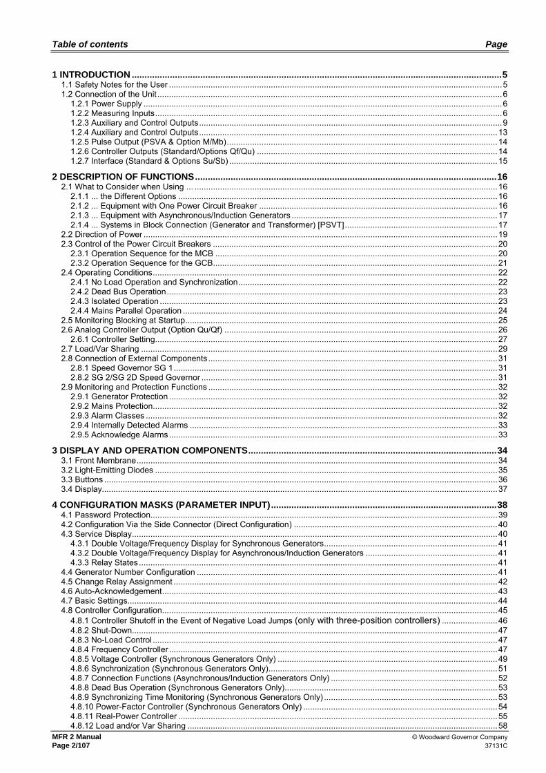
Table of contents Page
1 INTRODUCTION ..................................................................................................................................................5 1.1 Safety Notes for the User ................................................................................................................................................5 1.2 Connection of the Unit .....................................................................................................................................................6
1.2.1 Power Supply ...........................................................................................................................................................6 1.2.2 Measuring Inputs......................................................................................................................................................6 1.2.3 Auxiliary and Control Outputs...................................................................................................................................9 1.2.4 Auxiliary and Control Outputs.................................................................................................................................13 1.2.5 Pulse Output (PSVA & Option M/Mb).....................................................................................................................14 1.2.6 Controller Outputs (Standard/Options Qf/Qu) ........................................................................................................14 1.2.7 Interface (Standard & Options Su/Sb) ....................................................................................................................15
2 DESCRIPTION OF FUNCTIONS.......................................................................................................................16 2.1 What to Consider when Using ... ...................................................................................................................................16
2.1.1 ... the Different Options ..........................................................................................................................................16 2.1.2 ... Equipment with One Power Circuit Breaker .......................................................................................................16 2.1.3 ... Equipment with Asynchronous/Induction Generators .........................................................................................17 2.1.4 ... Systems in Block Connection (Generator and Transformer) [PSVT]..................................................................17
2.2 Direction of Power .........................................................................................................................................................19 2.3 Control of the Power Circuit Breakers ...........................................................................................................................20
2.3.1 Operation Sequence for the MCB ..........................................................................................................................20 2.3.2 Operation Sequence for the GCB...........................................................................................................................21
2.4 Operating Conditions.....................................................................................................................................................22 2.4.1 No Load Operation and Synchronization................................................................................................................22 2.4.2 Dead Bus Operation...............................................................................................................................................23 2.4.3 Isolated Operation ..................................................................................................................................................23 2.4.4 Mains Parallel Operation ........................................................................................................................................24
2.5 Monitoring Blocking at Startup.......................................................................................................................................25 2.6 Analog Controller Output (Option Qu/Qf) ......................................................................................................................26
2.6.1 Controller Setting....................................................................................................................................................27 2.7 Load/Var Sharing ..........................................................................................................................................................29 2.8 Connection of External Components .............................................................................................................................31
2.8.1 Speed Governor SG 1............................................................................................................................................31 2.8.2 SG 2/SG 2D Speed Governor ................................................................................................................................31
2.9 Monitoring and Protection Functions .............................................................................................................................32 2.9.1 Generator Protection ..............................................................................................................................................32 2.9.2 Mains Protection.....................................................................................................................................................32 2.9.3 Alarm Classes ........................................................................................................................................................32 2.9.4 Internally Detected Alarms .....................................................................................................................................33 2.9.5 Acknowledge Alarms..............................................................................................................................................33
3 DISPLAY AND OPERATION COMPONENTS..................................................................................................34 3.1 Front Membrane............................................................................................................................................................34 3.2 Light-Emitting Diodes ....................................................................................................................................................35 3.3 Buttons ..........................................................................................................................................................................36 3.4 Display...........................................................................................................................................................................37
4 CONFIGURATION MASKS (PARAMETER INPUT).........................................................................................38 4.1 Password Protection......................................................................................................................................................39 4.2 Configuration Via the Side Connector (Direct Configuration) ........................................................................................40 4.3 Service Display..............................................................................................................................................................40
4.3.1 Double Voltage/Frequency Display for Synchronous Generators...........................................................................41 4.3.2 Double Voltage/Frequency Display for Asynchronous/Induction Generators .........................................................41 4.3.3 Relay States...........................................................................................................................................................41
4.4 Generator Number Configuration ..................................................................................................................................41 4.5 Change Relay Assignment ............................................................................................................................................42 4.6 Auto-Acknowledgement.................................................................................................................................................43 4.7 Basic Settings................................................................................................................................................................44 4.8 Controller Configuration.................................................................................................................................................45
4.8.1 Controller Shutoff in the Event of Negative Load Jumps (only with three-position controllers) ........................46 4.8.2 Shut-Down..............................................................................................................................................................47 4.8.3 No-Load Control .....................................................................................................................................................47 4.8.4 Frequency Controller ..............................................................................................................................................47 4.8.5 Voltage Controller (Synchronous Generators Only) ...............................................................................................49 4.8.6 Synchronization (Synchronous Generators Only)...................................................................................................51 4.8.7 Connection Functions (Asynchronous/Induction Generators Only) ........................................................................52 4.8.8 Dead Bus Operation (Synchronous Generators Only)............................................................................................53 4.8.9 Synchronizing Time Monitoring (Synchronous Generators Only) ...........................................................................53 4.8.10 Power-Factor Controller (Synchronous Generators Only) ....................................................................................54 4.8.11 Real-Power Controller ..........................................................................................................................................55 4.8.12 Load and/or Var Sharing ......................................................................................................................................58

© Woodward Governor Company MFR 2 Manual 37131C Page 3/107
4.9 Configuration of Protection ............................................................................................................................................59 4.9.1 Generator Overload Monitoring ..............................................................................................................................59 4.9.2 Generator Reverse/Reduced Power Monitoring.....................................................................................................59 4.9.3 Unbalanced Load Monitoring..................................................................................................................................60 4.9.4 Definite Time-Overcurrent Protection .....................................................................................................................61 4.9.5 Ground Fault Monitoring (Option I3).......................................................................................................................62 4.9.6 Re-Active Power Monitoring ...................................................................................................................................63 4.9.7 Generator Frequency Monitoring............................................................................................................................64 4.9.8 Generator Voltage Monitoring ................................................................................................................................65 4.9.9 Mains Frequency Monitoring ..................................................................................................................................66 4.9.10 Mains Voltage Monitoring.....................................................................................................................................67 4.9.11 Asymmetry Monitoring..........................................................................................................................................68 4.9.12 Phase Shift Monitoring (Synchronous Generators Only) ......................................................................................69 4.9.13 df/dt Monitoring (PSVA & Option D) .....................................................................................................................70 4.9.14 Mains Decoupling.................................................................................................................................................71 4.9.15 Battery Voltage Monitoring ...................................................................................................................................71 4.9.16 Centralized Alarm.................................................................................................................................................71
4.10 Enable Monitoring .......................................................................................................................................................71 4.11 Configure Pulse Outputs .............................................................................................................................................72
4.11.1 Pulse counter for real power ((PSVA & option M) ................................................................................................72 4.11.2 Pulse counter re-active power (PSVA & option Mb) .............................................................................................72
4.12 Configure Analog Outputs (PSVA & Option A2/A4).....................................................................................................73 4.13 Interface ......................................................................................................................................................................74
4.13.1 Modbus RTU Slave (Option Su/Sb)......................................................................................................................74 4.13.2 Siemens DK3964 (Option Su/Sb).........................................................................................................................74 4.13.3 Profibus DP (Option Su/Sb) .................................................................................................................................75 4.13.4 CAN Bus Interface................................................................................................................................................76
4.14 Counter Configuration .................................................................................................................................................76 4.14.1 Setting of the Maintenance Call............................................................................................................................76 4.14.2 Setting of the Operation Hours Counter ...............................................................................................................76 4.14.3 Setting of the start counter ...................................................................................................................................77 4.14.4 Setting of the Energy Counter ..............................................................................................................................77 4.14.5 Current Slave Pointer Resetting ...........................................................................................................................78
4.15 Analog Inputs Configuration (Option T2) .....................................................................................................................78 4.15.1 Pt100 Input ...........................................................................................................................................................78 4.15.2 Scaleable Analog Input 0/4-20 mA .......................................................................................................................79 4.15.3 Input PTC 0-16.5 kΩ for Generator Temperature.................................................................................................81 4.15.4 Input 0-150 mV for Battery Current Monitoring.....................................................................................................81
4.16 Discrete Inputs Configuration ......................................................................................................................................83 4.17 Configure Password ....................................................................................................................................................84
5 COMMISSIONING..............................................................................................................................................85 6 APPENDIX .........................................................................................................................................................86
6.1 Interface (Standard, Terminals X1-X5)..........................................................................................................................86 6.1.1 Transmission Telegram..........................................................................................................................................86 6.1.2 Receiving Telegram ...............................................................................................................................................90
6.2 Interface (Option Su/Sb; Terminals Y1-Y5) ...................................................................................................................91 6.2.1 Transmission Telegram..........................................................................................................................................91 6.2.2 Receiving Telegram (Option Sb) ............................................................................................................................95
6.3 Framework Data for the Interfaces ................................................................................................................................97 6.3.1 Framework Data for the Procedure 3964 (TTY, RS232, RS485) ...........................................................................97 6.3.2 Framework Data for Hardware Handshaking RTS/CTS (RS232, RS422) ..............................................................97 6.3.3 Framework Data for the MOD Bus RTU Slave.......................................................................................................97 6.3.4 Framework Data for the CAN Bus ..........................................................................................................................98 6.3.5 Framework Data for the Profibus DP Slave............................................................................................................99
6.4 Technical Data ............................................................................................................................................................100 6.5 Dimensions..................................................................................................................................................................101 6.6 Wiring Diagram............................................................................................................................................................102
6.6.1 MFR 2S/PSV - Version for Synchronous Generators...........................................................................................102 6.6.2 MFR 2S/PSVA - Version for Synchronous Generators ........................................................................................103 6.6.3 MFR 2A/PSV - Version for Asynchronous/Induction Generators..........................................................................104 6.6.4 MFR 2S/PSVT - Version for synchronous generators ..........................................................................................105
7 LIST OF PARAMETERS..................................................................................................................................106

MFR 2 Manual © Woodward Governor Company Page 4/107 37131C
NOTE
These manual has been developed are intended for a unit fitted with all available options. In-puts/outputs, functions, configuration screens and other details described, which do not exist on your unit may be ignored.
ATTENTION
The present manual has been prepared to enable the installation and commissioning of the unit. On account of the large variety of parameter settings, it is not possible to cover every possible combination. The Manual are therefore only a guide. In case of incorrect entries or a total loss of functions, the default settings can be taken from the enclosed list of parameters.

© Woodward Governor Company MFR 2 Manual 37131C Page 5/107
1 Introduction
1.1 Safety Notes for the User
This documentation contains the relevant information for the normal use of the product described herein. It is intended to be read by qualified staff.
Danger notes The following notes are intended to guarantee your own personal safety as well as to protect the unit and other units connected to it against damages. Safety notes and warnings intended to prevent any danger to the life and health of users or maintenance personnel and to avoid any damage will be identified in this documentation by means of the symbols and terms listed below. Within the framework of this documentation, the signals and terms that are used have the following meaning:
DANGER !!!
The DANGER symbol draws your attention to dangers while the description indicates how to handle and/or avoid such hazards. Any non-observance may cause fatal or serious injuries as well as considerable damage to property.
WARNING !
If the warnings are not observed, the unit and any devices attached to it may be destroyed. Please take into account appropriate precautions.
ATTENTION
This symbol points to important notes concerning the mounting, installation, and connection of the unit. This note absolutely must be observed when connecting the unit.
NOTE
References to other notes and supplements as well as tables and lists are identified by means of the "i" symbol. Most of the referenced sections are included in the Annex.
Intended use This unit may only be used for the applications described in this manual. The prerequisite for a proper and safe operation of the product is correct transportation, storage, and installation as well as careful operation and maintenance.

MFR 2 Manual © Woodward Governor Company Page 6/107 37131C
1.2 Connection of the Unit
WARNING !
A circuit breaker must be provided near to the unit and in a position easily accessible to the operator. This must also bear a sign identifying it as an isolating switch for the unit.
NOTE
Inductivities connected (such as coils of operating current or undervoltage tripping devices, or auxiliary or power contacts) must be connected to a suitable interference suppressor.
1.2.1 Power Supply
8..36 V DC (in normal operation)
01
2
N
0 V
8..36 V DC
8..36 V DCD1C1
C1 = 47.000 uF / 40 VD1 = P600M
for 12 V DC systems
Power supply
Terminal Description Amax
0 Neutral point of the three-phase system or neutral terminal of the voltage transformer (Measuring reference point)
Solder lug
1 8-36 V DC, 15 W 2.5 mm² 2 0 V reference point 2.5 mm²
1.2.2 Measuring Inputs
NOTE
Starting with version V3.5013, the unit is equipped with an automatic rotary field detection and may therefore be used in three-phase systems with a clockwise rotary field (right-handed rotary field) as well as with a counter-clockwise rotary field (left-handed rotary field).
a.) Voltage Measuring Inputs
a.1) Version PSV& PSVA
• Generator
L1L2L3N
Generator voltage
MCB GCB
0 N
2021
22 L3L2L1
G
Terminal Measurement Description Amax 20 Generator voltage L1 2.5 mm² 21 Generator voltage L2 2.5 mm² 22 Generator voltage L3 2.5 mm² 0
direct or with measuring transformer
../100 V Neutral point of the 3-phase system/transformer 2.5 mm²

© Woodward Governor Company MFR 2 Manual 37131C Page 7/107
• Busbar
N
L1L2L3
Remanence voltage
Busbar voltage
2324
2324
L1
L2L1
L2
MCB GCB
G
Asynchronous
Synchronous
Terminal Measurement Description Amax 23 Busbar voltage L1 2.5 mm² 24
direct or ../100 V Busbar voltage L2 2.5 mm²
• Mains
L3L2L1
N
Mains voltage
MCB
52 L3
5150
L2L1
GCB
G
Terminal Measurement Description Amax 50 Mains voltage L1 2.5 mm² 51 Mains voltage L2 2.5 mm² 52 Mains voltage L3 2.5 mm² 0
direct or with measuring transformer
../100 V Neutral point of the 3-phase system/transformer 2.5 mm²
a.2) Version PSVT
• Generator Low voltage side - US
L1L2L3N
Generatorvoltage - US
MCB GCB0 N
2021
22 L3L2L1
G
see MFR 2/PSV
Terminal Measurement Description Amax 20 Generator voltage L1 - low voltage side - US 2.5 mm² 21 Generator voltage L2 - low voltage side - US 2.5 mm² 22 Generator voltage L3 - low voltage side - US 2.5 mm² 0
direct or with measuring transformer
../100 V Neutral point of the 3-phase system/transformer 2.5 mm²

MFR 2 Manual © Woodward Governor Company Page 8/107 37131C
• Generator High voltage side (OS)
L1L2L3N
Generatorvoltage - OS
MCB GCB
L2L1
G
see MFR 2/PSV
2423
Terminal Measurement Description Amax
23 Generator voltage L1 - high voltage side - OS 2.5 mm² 24
direct or ../100 V Generator voltage L2 - high voltage side - OS 2.5 mm²
• Mains
L1L2L3N
Mains voltage
MCB GCB
5051
52 L3L2L1
G
see MFR 2/PSV
Terminal Measurement Description Amax 50 Mains voltage L1 2.5 mm² 51 Mains voltage L2 2.5 mm² 52 Mains voltage L3 2.5 mm² 0
direct or with measuring transformer
../100 V Neutral point of the 3-phase system/transformer 2.5 mm²
b.) Current Measuring Inputs
WARNING !
Before detaching the secondary current transformer connections or the connections of the current transformer on the unit, make sure that it is shunted.
NOTE
Generally, current transformers are to be grounded secondary at one line.
• Generator
N
L2L3
L1
Detail:Connection of the transducers
S2
s2L..
Generatorcurrent
../1 A or ../5 A
s1 (k)..
L..s2 (l)..
MCB
GS1
s1
L332 s1 (k)
31 s2 (l)
3029
2625
s1 (k)s2 (l)
s2 (l)s1 (k)
L2
L1
GCB
G
Terminal Measurement Description Amax 25 Generator current L1, transformer terminal s2 (l) 2.5 mm² 26 Generator current L1, transformer terminal s1 (k) 2.5 mm² 29 Generator current L2, transformer terminal s2 (l) 2.5 mm² 30 Generator current L2, transformer terminal s1 (k) 2.5 mm² 31 Generator current L3, transformer terminal s2 (l) 2.5 mm² 32
Measuring transformer
../1 A or ../5 A
Generator current L3, transformer terminal s1 (k) 2.5 mm²

© Woodward Governor Company MFR 2 Manual 37131C Page 9/107
• Mains
L2L3
L1
N
GCBS1
s1
S2
s2
MCB
G
Mains current../1A or ../5 A
s1 (k)
2728
s2 (l)L1
Terminal Measurement Description Amax 27 Mains current L1, transformer terminal s2 (l) 2.5 mm² 28
Transformer ../1 A ../5 A Mains current L1, transformer terminal s1 (k) 2.5 mm²
1.2.3 Auxiliary and Control Outputs
NOTE
The common use of the analog outputs, the pulse output, the discrete inputs and the Pt100 temperature input is possible only under certain conditions. Because of the various project stages, there may be differences between the present user instructions and the delivered hardware.
a.) Discrete Inputs
• Control inputs
Release GCB
Signal device
Signal device
Reply GCB
Reply MCB
Signal device
CB
CB
Switchingsetpoint 1 setpoint 2
Reply: GCB is open
Release MCB
Reply: MCB is open
77
77
453
54
3
3
73
5
18..250 V (AC/DC)
Terminal Associated Common
Description (according to DIN 40 719 Part 3, 5.8.3)
Amax
Make contact 3 Enable GCB 2.5 mm² 5 Switching "Setpoint 1 ↔ 2" 2.5 mm²
53 7
Enable MCB 2.5 mm² Break contact
4 Reply: GCB is open 2.5 mm² 54 7 Reply: MCB is open 2.5 mm²
MFR 2 Manual © Woodward Governor Company Page 10/107 37131C
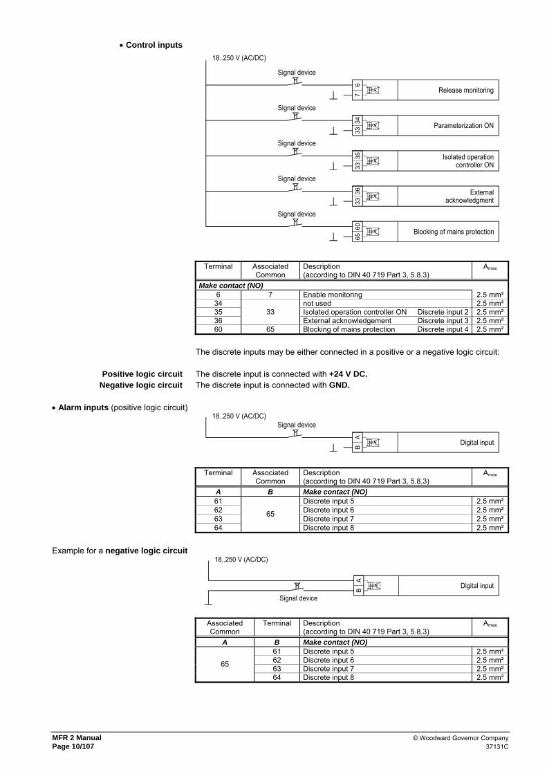
• Control inputs
Release monitoring
Parameterization ON
Isolated operationcontroller ON
Signal device
Signal device
Signal device
Signal device
3335
336
734
18..250 V (AC/DC)
Signal device
3336
6065
Externalacknowledgment
Blocking of mains protection
Terminal Associated Common
Description (according to DIN 40 719 Part 3, 5.8.3)
Amax
Make contact (NO) 6 7 Enable monitoring 2.5 mm²
34 not used 2.5 mm² 35 Isolated operation controller ON Discrete input 2 2.5 mm² 36
33 External acknowledgement Discrete input 3 2.5 mm²
60 65 Blocking of mains protection Discrete input 4 2.5 mm² The discrete inputs may be either connected in a positive or a negative logic circuit:
Positive logic circuit The discrete input is connected with +24 V DC. Negative logic circuit The discrete input is connected with GND.
• Alarm inputs (positive logic circuit)
18..250 V (AC/DC)
Digital input
AB
Signal device
Terminal Associated Common
Description (according to DIN 40 719 Part 3, 5.8.3)
Amax
A B Make contact (NO) 61 Discrete input 5 2.5 mm² 62 Discrete input 6 2.5 mm² 63 Discrete input 7 2.5 mm² 64
65
Discrete input 8 2.5 mm²
Example for a negative logic circuit 18..250 V (AC/DC)
Digital input
AB
Signal device
Associated Common
Terminal Description (according to DIN 40 719 Part 3, 5.8.3)
Amax
A B Make contact (NO) 61 Discrete input 5 2.5 mm² 62 Discrete input 6 2.5 mm² 63 Discrete input 7 2.5 mm² 65
64 Discrete input 8 2.5 mm²
© Woodward Governor Company MFR 2 Manual 37131C Page 11/107
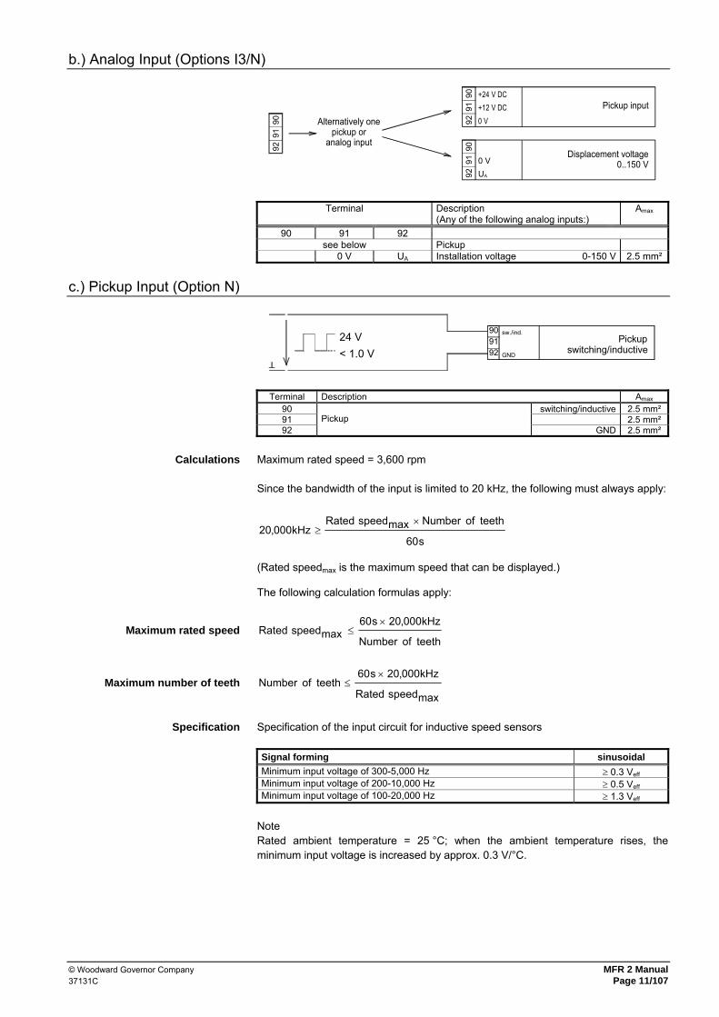
b.) Analog Input (Options I3/N)
91 +12 V DC
92 0 V
90 +24 V DCPickup input
Alternatively onepickup or
analog input
9291
90
Displacement voltage0..150 V91 0 V
92 UA
90
Terminal Description (Any of the following analog inputs:)
Amax
90 91 92 see below Pickup
0 V UA Installation voltage 0-150 V 2.5 mm²
c.) Pickup Input (Option N)
24 V Pickupswitching/inductive< 1.0 V
9091
GND92
sw./ind.
Terminal Description Amax 90 switching/inductive 2.5 mm² 91 2.5 mm² 92
Pickup GND 2.5 mm²
Calculations Maximum rated speed = 3,600 rpm
Since the bandwidth of the input is limited to 20 kHz, the following must always apply:
s60
teethofNumbermaxspeedRatedkHz000,20
×≥
(Rated speedmax is the maximum speed that can be displayed.) The following calculation formulas apply:
Maximum rated speed teethofNumber
kHz000,20s60maxspeedRated
×≤
Maximum number of teeth maxspeedRated
kHz000,20s60teethofNumber
×≤
Specification Specification of the input circuit for inductive speed sensors
Signal forming sinusoidal Minimum input voltage of 300-5,000 Hz ≥ 0.3 Veff Minimum input voltage of 200-10,000 Hz ≥ 0.5 Veff Minimum input voltage of 100-20,000 Hz ≥ 1.3 Veff
Note Rated ambient temperature = 25 °C; when the ambient temperature rises, the minimum input voltage is increased by approx. 0.3 V/°C.

MFR 2 Manual © Woodward Governor Company Page 12/107 37131C
Input voltage in dependence of the frequency [Ueff]
0
0,5
1
1,5
2
2,5
3
100 1000 10000 100000Frequency [Hz]
Effe
ctiv
e in
put v
olta
ge [V
]
Figure 1: Typical behavior of the input voltage sensitivity at an ambient temperature of 25 °C.
d.) Analog Inputs (PSVA & Option T2/X/Xc)
NOTE
The temperature measuring input is always configured in 3-conductor technology. If a 2-conductor resistance is used, the terminals 71/72, or 74/75 must be connected to each other using a jumper.
WARNING !
The analog inputs of the MFR are not isolated. When using an isolation monitor, we recommend to use two-pole, isolated transmitters.
The analog inputs for active transmitters (0 to 20 mA, 0 to 10V) should only be operated with two-pole, isolated transmitters.
GND
GND
C
aUAC
CA
BB
CA aI
BA
B
Analog inputPTC
Analog input0..150 mV
Analog input0/4..20 mA
Analog inputPt100
Terminal A B C
Description (any of the following analog inputs:)
Amax
70 71 72 Analog input 1 [1] • PSVA 0/4-20 mA, Setpoint value P • Option T2 Alternative aus:
Pt100, 0/4-20 mA, PTC (16,5 kOhm) • Option X 0/4-20 mA, Setpoint value P
2,5 mm²
73 74 75 Analog input 2 [2] • Option T2 Alternative aus:
Pt100, 0/4-20 mA, 0-150 mV • Option Xc 0/4-20 mA, Setpoint value cosphi
2,5 mm²

© Woodward Governor Company MFR 2 Manual 37131C Page 13/107
1.2.4 Auxiliary and Control Outputs
a.) Relay Outputs
• Power circuit breaker max. 250 V AC
Command: close GCB
Command: close MCB
Command: open MCB
Command: open GCBGCB
MCB
MCB
GCB
4142
1417
4039
1615
Root Switched Description Amax 14 15 Command: close GCB 2.5 mm² 16 17 Command: close MCB 2.5 mm² 39 40 Command: open MCB 2.5 mm² 41 42 Command: open GCB 2.5 mm²
• Relay (general)
AB
Relay outputexternal device
max. 250 V AC
Root Switched Description Amax A B 18 19 Readiness for operation 2.5 mm² 37 38 Relay output 4 2.5 mm² 43 44 Relay output 3 2.5 mm² 45 46 Relay output 2 2.5 mm² 47 48 Relay output 1 2.5 mm²
(RM)..configurable with the relay manager
b.) Analog Outputs (PSVA & Options A2/A4)
IAB 0 V
A Analog output
IA 0 V Description Amax A B 80 81 Analog output 0/4-20 mA PSVA/A2 1.5 mm² 82 83 Analog output 0/4-20 mA PSVA/A2 1.5 mm² Y1 Y2 Analog output 0/4-20 mA PSVA/A4 1.5 mm² Y5 Y4 Analog output 0/4-20 mA PSVA/A4 1.5 mm²
MFR 2 Manual © Woodward Governor Company Page 14/107 37131C
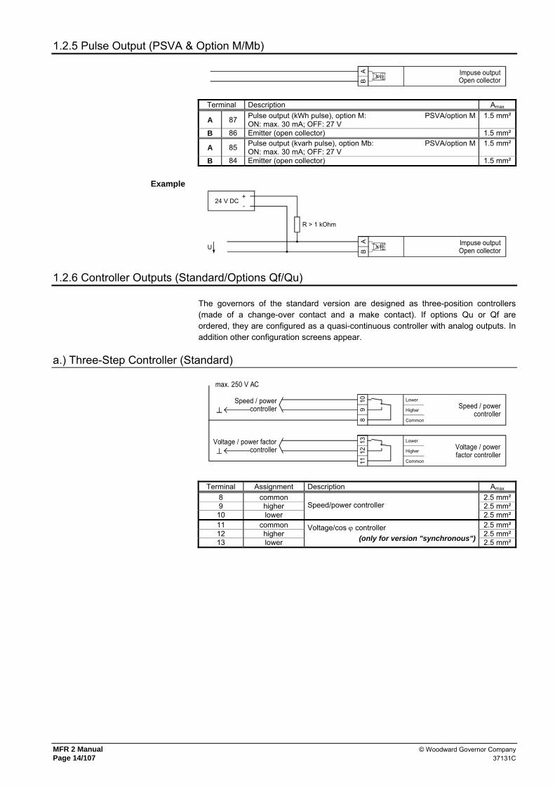
1.2.5 Pulse Output (PSVA & Option M/Mb)
BA Impuse output
Open collector
Terminal Description Amax
A 87 Pulse output (kWh pulse), option M: PSVA/option MON: max. 30 mA; OFF: 27 V
1.5 mm²
B 86 Emitter (open collector) 1.5 mm²
A 85 Pulse output (kvarh pulse), option Mb: PSVA/option MON: max. 30 mA; OFF: 27 V
1.5 mm²
B 84 Emitter (open collector) 1.5 mm²
Example
BA Impuse output
Open collector
+-
24 V DC
R > 1 kOhm
U
1.2.6 Controller Outputs (Standard/Options Qf/Qu)
The governors of the standard version are designed as three-position controllers (made of a change-over contact and a make contact). If options Qu or Qf are ordered, they are configured as a quasi-continuous controller with analog outputs. In addition other configuration screens appear.
a.) Three-Step Controller (Standard) 11
1213Voltage / power factor
controllerCommon
Higher
LowerVoltage / powerfactor controller
8 Common
Speed / powercontroller Speed / power
controller
max. 250 V AC
910 Lower
Higher
Terminal Assignment Description Amax 8 common 2.5 mm² 9 higher 2.5 mm²
10 lower Speed/power controller
2.5 mm² 11 common 2.5 mm² 12 higher 2.5 mm² 13 lower
Voltage/cos ϕ controller (only for version "synchronous") 2.5 mm²

© Woodward Governor Company MFR 2 Manual 37131C Page 15/107
b.) Analog Controller Output (Options Qf/Qu)
Speed / powercontroller
Voltage / cosphicontroller
AI
0 V0 V
AIAU
0 V
0 VUA
0 V0 V
U0 V
812
1113
AI
0 V0 V
A
A
I
U0 V10
9 0 VA
0 V
Terminal Assignment Description Amax I U
8 I 2.5 mm² 9 0 V UA 2.5 mm²
10 0 V 0 V Speed/power controller
2.5 mm² 11 I 2.5 mm² 12 0 V UA 2.5 mm² 13 0 V 0 V
Voltage/power factor controller (only for version "synchronous" ) 2.5 mm²
1.2.7 Interface (Standard & Options Su/Sb)
ACA B D E B DC E A B C D E CEA B C D A B D E
GN
D
Inte
rface
RS
422
inte
rface
Inte
rface
RS
232
inte
rface
A (n
on-in
verte
d)
B (in
verte
d)
GN
D
RTSRxD
CTS Tx
D
Inte
rface
RS
485
inte
rface
MO
D b
us R
TU s
lave
Z (in
verte
d)
Y (n
on-in
verte
d)
B (in
verte
d)
A (n
on-in
verte
d)
GN
D
Inte
rface
CAN
bus
Inte
rface
TTY
inte
rface
The
trans
mitt
er d
rives
the
curr
ent.
RxD
+
RxD
-
TxD
+
TxD
-
Term
inat
ion
NC
GN
D
CAN
-H
CAN
-L
DA B C
Inte
rface
Pro
fi bu
s D
P
Scr
een
A-Li
ne
GN
D
+5 V
E F
B-Li
ne
RTS
Terminal Description Whether the terminals are designated X or Y depends on the configuration of the system. Please refer to the wiring diagram (A = X/Y, B = X/Y, etc.). A (X1/Y1) B (X2/Y2) C (X3/Y3) D (X4/Y4) E (X5/Y5)
Standard CAN-H# CAN-L# GND CAN-H CAN-L CAN-Bus
Option Su/Sb RxD RTS GND CTS TxD RS232
GND B A RS485, MOD bus RTU slave RxD- RxD+ NC TxD- TxD+ TTY (transm. drives the current)
A (X1/Y1) B (X2/Y2) C (X3/Y3) D (X4/Y4) E (X5/Y5) F (X6/Y6) Option Su/Sb
Shield +5 V GND A- A-Line B-Line RTS Profi bus DP (use the file LEON00D9.GSD)
#..can be used to loop the CAN bus or/and to connect the termination resistance.
NOTE
Please note that the CAN bus must be terminated with an impedance which corresponds to the wave impedance of the cable (e.g. 120 Ohm).
NOTE
For the configuration via the configuration connector (direct configuration) you need a direct configuration cable (order code "DPC"), the program LeoPC 1 (supplied with the cable) and the corresponding configuration files. Please consult the online help installed when the program is installed for a description of the LeoPC 1 PC program and its setup.

MFR 2 Manual © Woodward Governor Company Page 16/107 37131C
2 Description of Functions
2.1 What to Consider when Using ...
2.1.1 ... the Different Options
The MFR 2/PSV consists of a base unit that can also be expanded with options. As a result, a multitude of different units adapted to the particular use is possible. The particular options that a specific unit includes can be derived from the nameplate. These manual describes the basic unit and all options, regardless of the restriction that the options cannot be combined in any desired manner. Likewise, the connection diagram is labeled for all conceivable connection possibilities. For a particular unit, one must via the options choose the connection terminals and the chapter and reference in the manual that are pertinent to the unit in question.
2.1.2 ... Equipment with One Power Circuit Breaker
The MFR 2/PSV is designed for systems with two power circuit breakers (mains power circuit breaker MCB and generator power circuit breaker GCB). However, it is also possible to operate systems with only one power circuit breaker. It is also advisable to trigger this breaker from the unit as a GCB and to connect the corresponding terminals. Moreover, the following applies: • If the generator is only operated in isolated operation or isolated parallel operation,
the following applies: - "Reply: MCB is open" (term. 54): HIGH-signal (log. "1") and - "Enable MCB" (term. 53): LOW signal (logical "0").
• If the generator is only operated in mains parallel operation, the following applies: - "Reply: MCB is open" (term. 54): LOW-Signal (logical "0") und - "Enable MCB" (term. 53): HIGH signal (logical "1").
The type and manner of system operation must be taken into account in the configuration of the monitoring.

© Woodward Governor Company MFR 2 Manual 37131C Page 17/107
2.1.3 ... Equipment with Asynchronous/Induction Generators
If systems with systems with asynchronous/induction generators are used, the following must be noted: • According to the concept of an an asynchronous/induction generator there is no
voltage and power factor controller. • Systems with asynchronous/induction generators are 1 CB systems. Only the GCB
is operated. • Connect the remanent voltage to terminals 23/24. Terminal 23/24 has a zoom func-
tion as long as the unit is not operated mains parallel, as the unstimulated synchronous generator is not yet able to generate voltage. Control is carried out on the basis of voltage measurement at terminals 20/21/22 and 50/51/52. Terminal 20 must thus be connected to terminal 23 and terminal 21 to terminal 24.
• Make sure that the input "Reply: MCB is open" is controlled by a continuous LOW-signal (e.g. do not connect or link with the terminal 7 "Common").
• Connect the terminal 53 "Enable MCB" to a continuous HIGH-signal (e.g. connect with the terminal 1 "Power supply"). This informs the unit that it is in mains parallel operation. Power control is carried out.
• The relay "Command: close MCB" and "Command: open MCB" and the LED "Mains CB on" have no function.
• The generator frequency control (see chapter 4.9.7) and blocking control when starting (see chapter 2.5) respond on the measured frequency of the remanence voltage or generator voltage.
• The generator voltage control (see chapter 4.9.8) becomes only active if the GCB is closed.
• There is no synchronization time control.
2.1.4 ... Systems in Block Connection (Generator and Transformer) [PSVT]
The version MFR 2/PSVT is adjusted for systems in which generator and transformer are connected directly.
NOTE
The version "PSVT" can operate only one circuit breaker. Thereby the synchronization voltage is measured twice directly at the circuit breaker. The third measuring point (current and voltage) is used only for generator protection. As this measuring point is taken separatly and independent of both synchronization voltages, the phase shift caused by the transformer can be ignored.
Schematic circuit diagram
poss.MCB GCB
G
Igen
Ugen
US
Ugen
OS
Umai
ns
Imai
ns
The individual measuring points have the following functions: • Voltage, generator US = protection and monitoring • Current, generator = protection and monitoring • Voltage, generator OS = synchronization and monitoring • Voltage, mains = protection, synchronization and monitoring • Current, mains = measuring and monitoring

MFR 2 Manual © Woodward Governor Company Page 18/107 37131C
Concerning the configuration and functionality of the MFR 2/PSVT there are devia-tions compared with MFR 2/PSV or MFR 2/PSVA which were not described in the dif-ferent chapters. These are resumed in the following: • The MFR 2/PSVT can operate only the generator circuit breaker (GCB). • The "Reply: MCB is open" is used to realize mains parallel operation. The LED
"Mains-CB ON" indicates the response of the MCB. If the system has no separate MCB and the connection to the mains is made by closing the GCB, the input "Re-ply: MCB is open" has to be connected steady with 0 V.
• The discrete input "Enable MCB" may not be attached or should be connected with 0 V.
• As no MCB is operated, all screens and service monitoring referring to the MCB do not apply.
• There is no dead bus operation function. • There is no busbar voltage, but a "generator voltage of the low voltage side" and a
"generator voltage of the high voltage side". By using these terms it is assumed that the low voltage side of the transformer is directly connected with the generator and the high voltage side is connected with the mains (as a version of this definition the MFR 2 can also operate higher voltages on the low voltage side than on the high voltage side.).
• The mains voltage (terminals 50/51) and the generator voltage high voltage side (terminals 23/24) are the voltages used to synchronize the GCB.
• The service monitoring is only used to display the both voltages which have to be synchronized.
• The measurement of generator current and generator voltage of the low voltage side are used for generator protection only.
• A possible phase shift between high and low voltage side caused by the trans-former is not relevant for the functions of the MFR 2/PSVT.

© Woodward Governor Company MFR 2 Manual 37131C Page 19/107
2.2 Direction of Power
If the unit's current transformers are wired according to the pin diagram shown, the following values are displayed: • Positive generator real power The generator supplies real load • Lagging generator power factor cos ϕ The generator is overexcited and
supplies lagging re-active power • Positive mains real power Real load is supplied to the mains • Lagging mains power factor cos ϕ The mains pick up lagging re-active
power
S1 (K)
S2 (L)
S2 (L)
S1 (K)
MFR 2
26
25
s1 (k)
G
s2 (l)
28
27
s1 (k)
s2 (l)
pospos
PP
indind
pospos
PP
indind
generator circuit breakerGCB
mains circuit breakerMCB
MAINS
BUSBAR
GENERATOR

MFR 2 Manual © Woodward Governor Company Page 20/107 37131C
2.3 Control of the Power Circuit Breakers
2.3.1 Operation Sequence for the MCB
The diagram below is only applicable if the following is set on the unit: - MCB open via MCB release: ON - Relay "Command: open MCB", Logic: A Additional information can be obtained from the descriptions of the input screens.
1
3
2 4
5 6
'Command: closeMCB' (16/17)
Time/s
Time/s
Time/s
Time/s
ReleaseMCB (53/7)
‘Command: openMCB' (39/40)
'Reply: MCB isopen' (54/7)
Connection time MCB
On/off switching pulse 1 Synchronization MCB 2 MCB CLOSE: 2 closing pulse for MCB set; 1 switcher time delay; 4 switch-
on impulse deleted; 5 Open MCB: 5 opening pulse MCB set; 6 switch-off impulse deleted.

© Woodward Governor Company MFR 2 Manual 37131C Page 21/107
2.3.2 Operation Sequence for the GCB
The diagram below only applies if the following is set on the unit: - Stoppage: ON - Relay "Command: open GCB", logic: A - Generator switch continuous pulse: OFF
Additional information can be derived from the descriptions of the input screens.
1
3
2 4
6 7
'Command: closeGCB' (14/15)
Time/s
Time/s
Time/s
Time/s
ReleaseGCB (3/7)
'Command: openGCB' (41/42)
'Reply: GCB isopen' (4/7)
Connection time GCB
5
Closing/opening pulse 1 Synchronization GCB 2 GCB CLOSE: 2 closing pulse GCB set; 3 switcher time delay; 4 switch-on
impulse deleted; 6 OPEN GCB: 5 beginning of the power reduction; 6 end of the power
reduction; Opening pulse GCB set 7 switch-off impulse deleted Between 5 and 6 the power is reduced. When the power is close to zero "0", the GCB is opened.
MFR 2 Manual © Woodward Governor Company Page 22/107 37131C
2.4 Operating Conditions
2.4.1 No Load Operation and Synchronization
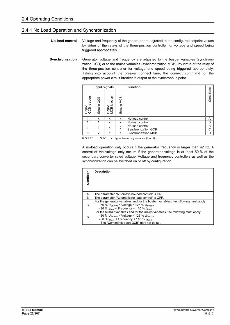
No-load control Voltage and frequency of the generator are adjusted to the configured setpoint values by virtue of the relays of the three-position controller for voltage and speed being triggered appropriately.
Synchronization Generator voltage and frequency are adjusted to the busbar variables (synchroni-zation GCB) or to the mains variables (synchronization MCB), by virtue of the relay of the three-position controller for voltage and speed being triggered appropriately. Taking into account the breaker connect time, the connect command for the appropriate power circuit breaker is output at the synchronous point.
Input signals Function R
eply
: G
CB
is o
pen
Ena
ble
GC
B
Rep
ly:
MC
B is
ope
n
Ena
ble
MC
B
Con
ditio
ns
1 x x x No-load control A 1 1 x x No-load control B
1 1 x 0 No-load control Synchronization GCB
B C
0 x 1 1 Synchronization MCB D 0: "OFF" 1: "ON" x: Signal has no significance (0 or 1)
A no-load operation only occurs if the generator frequency is larger than 42 Hz. A control of the voltage only occurs if the generator voltage is at least 50 % of the secondary converter rated voltage. Voltage and frequency controllers as well as the synchronization can be switched on or off by configuration.
Con
ditio
n Description
A The parameter "Automatic no-load control" is ON. B The parameter "Automatic no-load control" is OFF.
C For the generator variables and for the busbar variables, the following must apply: - 50 % USetpoint < Voltage < 125 % USetpoint - 80 % fRated < Frequency < 110 % fRated
D
For the busbar variables and for the mains variables, the following must apply: - 50 % USetpoint < Voltage < 125 % USetpoint - 80 % fRated < Frequency < 110 % fRated - The "Command: open GCB" may not be set.

© Woodward Governor Company MFR 2 Manual 37131C Page 23/107
2.4.2 Dead Bus Operation
Dead bus operation Output of a connect command for the power circuit breaker without synchronization.
Input signals Function
Rep
ly:
GC
B is
ope
n
Ena
ble
GC
B
Rep
ly:
MC
B is
ope
n
Ena
ble
MC
B
Con
ditio
ns
1 1 1 0 GCB dead bus operation E 1 x 1 1 MCB dead bus operation F
0: "OFF" 1: "ON" x: Signal has no significance (0 or 1)
The busbar must be de-energized. In the case that several MFR 2 were connected via CAN bus, a dead bus operation blocking of the GCB is active. That means that from the units which got a release for dead bus operation only that unit with the smallest generator number gets a switch-on command for the GCB. All other units do not issue a switch-on command. In this way it is prevented that asynchronous generator voltages were connected via CAN bus by simultaneous dead bus operation commands. The presence of the CAN bus connec-tion has to be controlled in the display in automatic mode.
Con
ditio
n Description
E The parameter "Gen. circuit br. dead bus op." is ON and the generator voltage and frequency are within the configured limits.
F
The parameter "Mains circuit br. dead bus op." is ON and is valid for the mains values:
- 50 % USetpoint < Voltage < 125 % USetpoint - 42 Hz < Frequency < 110 % frated
2.4.3 Isolated Operation
Isolated operation Voltage and frequency of the generator are adjusted to the configured setpoint values, by virtue of the relay of the three-position controller for voltage and speed being triggered appropriately.
Input signals Function
Isol
atin
g co
ntro
ller O
N
Rep
ly:
GC
B is
ope
n
Ena
ble
GC
B
Rep
ly:
MC
B is
ope
n
Ena
ble
MC
B
Con
ditio
ns
0 0 x 1 0 no action 1 0 x 1 0 Isolating control
0: "OFF" 1: "ON" x: Signal has no significance (0 or 1)
A control in isolated operation only takes place if the generator frequency is greater than 42 Hz. A control of the voltage only takes place if the generator voltage is at least 80 % of the secondary transformer rated voltage and the parameter "Voltage controller isolated operation" is set to ON". Voltage and frequency controller as well as the synchronization can be switched on or off by configuration.

MFR 2 Manual © Woodward Governor Company Page 24/107 37131C
2.4.4 Mains Parallel Operation
Mains parallel operation Real power and power factor of the generator are adjusted to the configured setpoint values, by virtue of the relay of the three-position controller for power factor (voltage) and power (speed) being switched appropriately.
Input signals Function
Isol
atin
g co
ntro
ller O
N
Rep
ly:
GC
B is
ope
n
Ena
ble
GC
B
Rep
ly:
MC
B is
ope
n
Ena
ble
MC
B
Con
ditio
ns
x 0 x 0 x Mains parallel operation 0: "OFF" 1: "ON" x: Signal has no significance (0 or 1)
Mains parallel operation takes place only if the generator frequency is greater than 42 Hz. Note: if during mains parallel operation the generator frequency falls below 50 % of the rated value, the relay "Command: open GCB" is activated.

© Woodward Governor Company MFR 2 Manual 37131C Page 25/107
2.5 Monitoring Blocking at Startup
In order to prevent undesired triggering of the generator protection when stopping and starting the generator, the release of monitoring is linked to reaching of a generator minimum frequency and the discrete input "Enable monitoring". The type and manner of linking is explained in the following diagram. This type of release includes exclusively the following watchdogs: - Generator undervoltage - Generator undervoltage (generator underspeed with option N) - Reverse/reduced power When the minimum frequency is exceeded, this is indicated by closing the relay configured for this.. Whether or not the watchdogs are released and thus active can be recognized on the "Monitoring" LED on the pressure sensitive front membrane.
Time [s]
Time [s]
Time [s]
Time [s]
Time [s]
Time [s]
Gen
erat
orfre
quen
cy [H
z]
Delay(parameterization
mask B)
Monitoring ON after 00s
Delay(parameterization
mask B)
Parameterization mask B
Case 2
LED'Monitoring ON'
(Protection is active)
'ReleaseMonitoring ON'
(Terminal 6)
Relay'ON'
Case 1
LED'Monitoring ON'
(protection is active)
'ReleaseMonitoring ON'
(Terminal 6)
Minimum frequency für monitoring(parameterization mask A)
Monitoring ON at f gen > 00Hz
Parameterization mask A

MFR 2 Manual © Woodward Governor Company Page 26/107 37131C
2.6 Analog Controller Output (Option Qu/Qf)
As an alternative to a three-position controller output, the unit may also be equipped with an analog controller output. Other configuration masks then appear in configuration mode. The analog PID controller forms a closed-loop control loop together with the controlled system (usually a first-order lag element). The parameters of the PID controller (proportional-action coefficient KPR, derivative-action time TV and reset time Tn) can be modified individually. The configuration screens are used for this purpose.
Control loop Kp T1
Controlled system (PT1)PID controller
Kpr Tn Tv
Lag element (Tt)
Influencinyquantity Tt
If an abrupt disturbance variable is applied to the control loop, the reaction of the controlled system can be recorded at the output as a function of time (step response).
Step response (example)
0 t/s
x
TT
1
0T
xx d
m
x d
x m
T
Rise time
OvershootSystem deviation
rise
rise
Tolerance band
Settling timesett
sett Various values can be obtained from the step response; these are required for adjusting the controller to its optimum setting:
Rise time Trise Period starting when the value of the control variable leaves a predefined tolerance range for the control variable following a jump in the disturbance variable or reference input variable and ending the first time the value re-enters this range.
Settling time Tsettling Period starting when the value of the control variable leaves a predefined tolerance range for the control variable following a step in the disturbance variable or reference input variable and ending when the value re-enters this range permanently.
Overshoot xm Highest transient setpoint value deviation during the transition from one steady-state condition to a new steady-state condition following modification of the disturbance variable or reference input variable (xm optimum ≤ 10 %).
System deviation xd Permanent deviation from the final value (PID controller: xd = 0). By different conversions from these values, the values KPR, Tn and TV can be determined. Moreover, it is possible, by performing various calculations, to determine the optimal controller settings, e.g. by calculating compensation or adjustment of the time constants, T-sum rule, symmetric optimum, Bode-diagram. Other setting procedures and information may be obtained from current literature.

© Woodward Governor Company MFR 2 Manual 37131C Page 27/107
2.6.1 Controller Setting
ATTENTION
The following must be observed regarding the controller setting:
• Ensure that the emergency shutdown system is ready for use. • While determining the critical frequency, pay attention to the amplitude and frequency. • If the two values change uncontrollably:
EMERGENCY SHUTDOWN
a.) Initial State
Initial state The start position of the controller is determined using the initial state of the controller. If the controller is switched off, the basic setting can be used to output a fixed controller position.
Starting point Freq. 000%
Initial state frequency controller 0-100 %
Analog controller output setting with controller switched off. This value is also used as the initial value.
Starting point Voltage 000%
Voltage controller initial state 0-100 %
Analog controller output setting with controller switched off. This value is also used as the initial value.
b.) General Settings
The setting rule described below only serves as an example. Whether this method is suitable for setting your particular controlled system has not been and cannot be taken into account as each controlled system behaves uniquely. There are various methods of setting a controller. The setting rules of Ziegler and Nichols are explained below (determination for abrupt disturbances on the system input); this setting method assumes a pure lag element connected in series with a first-order lag system. 1. Controller operated as a P-only controller
(where Tn = ∞ [screen setting: Tn = 0], TV = 0). 2. Increase gain KPR (P-gain) until the control loop oscillates continuously at
KP = KPcrit.
Attention If the unit starts to oscillate uncontrollably, carry out an emergency shutdown and alter the screen setting accordingly.
3. At the same time: measure the critical cycle duration Tcrit 4. Set the parameters: PID controller PI controller KPR = 0.6 × KPcrit KPR = 0.45 × KPcrit Tn = 0.5 × Tcrit Tn = 0.83 × Tcrit TV = 0.125 × Tcrit

MFR 2 Manual © Woodward Governor Company Page 28/107 37131C
Step response
Controller setting Optimum (xm ≤ 10 %)
Controller setting Tcrit
Controller setting incorrect
0
1
x
0 t/s 00
1
x
t/s 0
1
x
0 t/s
Pr.sensitivity Kpr=000
P gain (KPR) Proportional action coefficient 1-240
The proportional-action coefficient KPR indicates the closed-loop control system gain. The variable to be controlled is achieved more rapidly by increasing the P-gain.
Reset time Tn=00.0s
Reset time (Tn) 0.2-60.0 s
The reset time Tn represents the I-component of the PID controller. The I-component results in permanent control deviation being eliminated in the controlled state.
Derivative act. time(xxxx) 0.00s
Derivative-action time (TV) 0.00-6.00 s
Derivative-action time TV represents the D-component of the PID controller. An increase in the phase reserve (stability) and the attenuation results from increasing this parameter.

© Woodward Governor Company MFR 2 Manual 37131C Page 29/107
2.7 Load/Var Sharing
Control guarantees that, in isolated operation (in parallel with other gensets or reverse synchronization of the busbar to the mains), the real power (in reference to the relevant rated power) is evenly distributed over all generators operating in parallel to the busbar.
Isolated operation in parallel Each controller involved in distribution control influences the generator to which it is assigned in such a manner that the rated frequency (main control variable) which has been configured remains constant. All units are interlinked via a CAN bus, via which any deviation in real power can be determined for each generator. This control variable is taken into consideration on controlling the frequency. The weighting, with which the secondary and the main control variable (= "reference variable") are processed, can be set via a factor. In controlled state, the isolated system has the set rated frequency, whereby the total real power (in reference to the relevant rated power) is subdivided equally amongst those generators involved in distribution control.
Note 1. The generator rated frequencies (page 44) absolutely must be set for all units
involved in distribution control at the same values for each. 2. The rated power of all participating units should not differ more than 50 % other-
wise the quality of the distribution afflicts. 3. The direct configuration via the lateral plug has to be de-activated otherwise the
CAN bus is out of operation. 4. The CAN bus connection is correct, if the right number of units connected via the
CAN bus is shown in the display. 5. The discrete input "Isolated controller ON" must be set. 6. The adjusted power limitation has higher priority than the distribution. 7. The parameter "Load sharing" and var sharing" must be set equally in all con-
nected units.
Description of the interface for the distribution control system
To guarantee a trouble-free
operation, please observe the following:
Distribution control is based on a multi-master-capable bus between the units. This structure enables the parallel operation of up to 8 generators. 1. The bus length must not exceed 250 m. 2. Each end of the bus must be terminated with terminating resistors which
correspond to the wave impedance of the bus cable (approx. 120 Ω). 3. The structure of the bus must be linear. Dead-end feeders are not permissible. 4. Shielded "Twisted-Pairs" are to be preferred as bus cables (example: Lappkabel
Unitronic LIYCY (TP) 2×2×0.25, UNITRONIC-Bus LD 2×2×0.22). 5. The bus cable may not be laid in the vicinity of strong current lines.
Wiring diagram
Terminalresistance
Note:The termination must beeffected with a resistorwhich corresponds to thewave impedance of theused cable (e. g. 120 )
CAN bus
X4
CA
N-H
CAN
-L
GN
D
X1 X2 X3
Term
inat
ion
X5
Ω
CAN bus
CA
N-H
X1Terminalresistance
CAN
-L
CA
N-H
CAN
-L
X5
GN
D
X3X2 X4
CAN
-L
X2
CA
N-H
X1
CAN bus
Term
inat
ion
X4
GN
D
X3 X5

MFR 2 Manual © Woodward Governor Company Page 30/107 37131C
Whether, and the manner in which, a unit carries out real power or frequency control in isolated operation in parallel with other generators, is defined by the "real power distribution reference variable." parameter in % in Chapter 4.8.12 "Load and/or Var Sharing" on page 58 of this manual. In this case, 10 % means increased real power control, and 99 % increased frequency control. This parameter must be input individually for each unit. In the case of the following control system, it must be noted that each unit calculates the mean utilization factor of all units from the data transmitted via the CAN bus, and then compares this with its own utilization factor. The utilization factor is compared with the reference variable, and results in the new reference variable. Frequency and real power control are simultaneously carried out in these units (corresponding to the reference variable).
P
f
actual [kW]
nominal [kW]
actual [Hz]
Utilization factor of this engine [%]
P
PPΣ
Calculation
actual (via CAN)
diff [%]
f
PΣ
set
nominal (via CAN)
Leading value 10..99 [%]
10 % = only P control 99 % = only f control
P
P
Calculation
2001-08-06 Leistungsverteilung Blockschaltbild.skf
actual [kW]
n actual [min-1]

© Woodward Governor Company MFR 2 Manual 37131C Page 31/107
2.8 Connection of External Components
2.8.1 Speed Governor SG 1
NOTE
Please note the wiring diagram for the SG 1. 180 Hz version pickups are supported.
8910
IaGND
+ (IN)- (OUT)
SG 156
Analog output 20 mA
Determination of the percentage Divisor = ( fPickup × 13 ) / 2,400 Hz fPickup = Number of teethPickup [Number] × Rated speedaggregate [min-1] × 1/60 [s]
Example Number of Pickup teeth = 158 teeth Rated unit speed = 1,500 min-1
fPickup = 158 teeth× 1,500 min-1 × 1/60 s = 3,950.00 Hz Divisor = ( 3,950.00 Hz × 13 ) / 2,400 Hz = 21.40 Setting on the PCB = 2 × 101 and 1 × 100 For the Pickup with the number of teeth 158/133/175 teeth, the setting must be 21/18/23.
2.8.2 SG 2/SG 2D Speed Governor
NOTE
Please note the wiring diagram for the SG 2/SG 2D. The LeoPC1 program is required for configuration of the speed governor.
8910
109
12SG 2 / SG 2D0 V DC+24 V DC
LowerHigher
CommonThree-position controller
LowerHigherCommon
87 + (IN)
- (OUT)
SG 2 / SG 2D8910
IaGND
Analog output 20 mA

MFR 2 Manual © Woodward Governor Company Page 32/107 37131C
2.9 Monitoring and Protection Functions
2.9.1 Generator Protection
The generator protection consists of the watchdogs for generator over-/undervoltage, generator over-/underfrequency as well as overload, reverse/reduced load, unbalanced load, overcurrent and re-active power (lagging/leading). With the exception of the overload, the triggering of a watchdog leads to activation of the relay "Command: open GCB". Each watchdog must be enabled separately via configuration. Moreover, each watchdog can be assigned to one or more signal relays.
2.9.2 Mains Protection
The mains protection consists of the watchdogs for mains over-/undervoltage, mains over-/undervoltage as well as phase shift, asymmetry and df/dt monitoring (only with option D). The mains decoupling in triggering of a mains failure is continually active and can be set via the configuration on the relay "Command: open GCB" or the relay "Command: open MCB". Every watchdog must be enabled separately via the configuration. Moreover, every watchdog can be assigned to one or more signal relays.
2.9.3 Alarm Classes
The monitoring functions are divided into four alarm classes:
F0 Warning alarm This alarm does not cause an interruption of the operation. An output is made without centralized alarm.
Alarm text + configured signaling relay F1 Warning alarm This alarm does not cause an interruption of the operation. Output of the centralized
alarm. Alarm text + flashing LED "Alarm" + relay centralized alarm fault (horn)
+ configured alarm relay F2 Triggering alarm This alarm causes a shutoff of the generator. The real power is first reduced before
the GCB is opened. Alarm text + flashing LED "Alarm" + relay centralized alarm (horn) + transmit
+ configured signaling relay F3 Triggering alarm This alarm leads to the immediate triggering of the relay "Command: open GCB".
Alarm text + flashing "Alarm" LED + group alarm relay (horn) + shutdown + configured signaling relay

© Woodward Governor Company MFR 2 Manual 37131C Page 33/107
2.9.4 Internally Detected Alarms
Type of alarm Alarms- class
Alarm text
Generator overfrequency F3 Gen.Overfreq. Generator underfrequency F3 Gen.Underfreq. Generator overvoltage F3 Gen.Overvolt. Generator undervoltage F3 Gen.Undervolt. Battery undervoltage F1 Batt. Undervolt. Generator overload F2 Gen. Overload Generator reverse/reduced load F3 Rev./red. load Mains overfrequency F0 Mains Overfreq. Mains underfrequency F0 Mains Underfreq. Mains overvoltage F0 Mains Overvolt. Mains undervoltage F0 Mains Undervolt. Mains asymmetry F0 Asymmetry Mains phase shift F0 Phase shift Mains df/dt fault (option D) F0 Fault df/dt Displacement voltage (option I3) F3 ground fault Generator time-overcurrent, level 1 F3 Gen.Overcurrent 1 Generator time-overcurrent, level 2 F3 Gen.Overcurrent 2 Generator unbalanced load F3 Unbalanced lo. Generator re-active power, lagging F3 Lead.react.load Generator re-active power, leading F3 Lagg.react.load Synchronization time fault F1 Synchr.TimeContr Interface fault (option Sb) F1 Interface Generator overtemperature (option T1,T2) F1 Gen.-over temp. Analog input 1 (0/4-20 mA), warning (option T1/T2) F1 Anin 1 Warning Analog input 1 (0/4-20 mA), shutdown (option T1/T2) F1 Anin 1 Tripping Analog input 1 (4-20 mA), wire break (option T1/T2) F0 Anin 1 Wire break Analog input 2 (0/4-20 mA), warning (option T1/T2) F1 Anin 2 Warning Analog input 2 (0/4-20 mA), shutdown (option T1/T2) F1 Anin 2 Tripping Analog input 2 (4-20 mA), wire break (option T1/T2) F0 Anin 2 Wire break Battery overcurrent, level 1 (option T1/T2) F1 Batt. over current 1 Battery overcurrent, level 2 (option T1/T2) F1 Batt. over current 2 Temperature 1, warning F1 Temp 1 warning Temperature 1, shutdown F3 Temp 1 tripping Temperature 1, wire break F0 Temperature 2, warning F1 Temp 2 warning Temperature 2, shutdown F3 Temp 2 tripping Temperature 2, wire break F0 Centralized alarm
Note: All fault states can be freely assigned to the signaling relay in configuration mode.
Please notice the maximum 4 alarm texts can be displayed! If more than 4 alarms are active at the same time, only the messages of the first four alarms can be displayed.
2.9.5 Acknowledge Alarms
By pressing the "Clear" button, the signaling relay, the group alarm message and the alarm messages in the LCD display are acknowledged: short acknowledgement (1 s) Acknowledgement of the group alarm message and
the alarm messages of class F0 and F1 Long acknowledgement (5 s) Acknowledgement of the group alarm message and
the alarm messages of class F2 and F3 For alarms of class F0 the signal relay is automatically acknowledged after the triggering condition has been taken away. Refer to the descriptions of configuration screens for additional information.
MFR 2 Manual © Woodward Governor Company Page 34/107 37131C
3 Display and Operation Components
3.1 Front Membrane
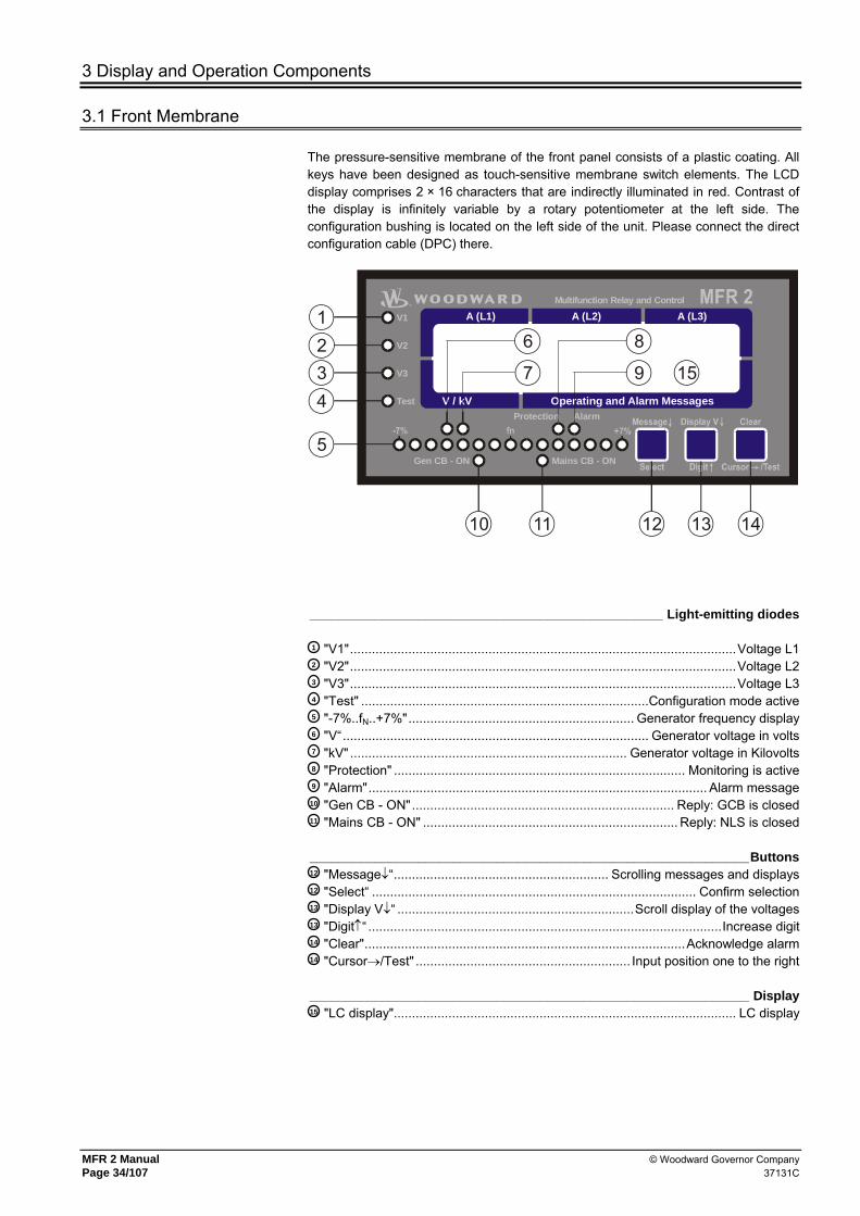
The pressure-sensitive membrane of the front panel consists of a plastic coating. All keys have been designed as touch-sensitive membrane switch elements. The LCD display comprises 2 × 16 characters that are indirectly illuminated in red. Contrast of the display is infinitely variable by a rotary potentiometer at the left side. The configuration bushing is located on the left side of the unit. Please connect the direct configuration cable (DPC) there.
Gen CB - ON Mains CB - ON
Protection Alarm
V1
V2
V3
Test
Multifunction Relay and Control
A (L1) A (L2) A (L3)
V / kV Operating and Alarm Messages
15
1234
5
10 11 12 13 14
9
8
7
6
_________________________________________________ Light-emitting diodes
1 "V1"..........................................................................................................Voltage L1 2 "V2"..........................................................................................................Voltage L2 3 "V3"..........................................................................................................Voltage L3 4 "Test" ...............................................................................Configuration mode active 5 "-7%..fN..+7%".............................................................. Generator frequency display 6 "V“.................................................................................... Generator voltage in volts 7 "kV" ............................................................................ Generator voltage in Kilovolts 8 "Protection" ................................................................................ Monitoring is active 9 "Alarm"............................................................................................. Alarm message
10 "Gen CB - ON"........................................................................ Reply: GCB is closed 11 "Mains CB - ON" ...................................................................... Reply: NLS is closed _____________________________________________________________Buttons 12 "Message↓“........................................................... Scrolling messages and displays 12 "Select“ ......................................................................................... Confirm selection 13 "Display V↓“ .................................................................Scroll display of the voltages 13 "Digit↑“ .................................................................................................Increase digit 14 "Clear"........................................................................................Acknowledge alarm 14 "Cursor→/Test" ........................................................... Input position one to the right _____________________________________________________________ Display 15 "LC display".............................................................................................. LC display

© Woodward Governor Company MFR 2 Manual 37131C Page 35/107
3.2 Light-Emitting Diodes
1 2 3 ............................LED "V1..V2..V3"
Voltage control Color "GREEN"
The light-emitting diodes "V1", "V2" and "V3" indicate which voltage (UL1N, UL2N, UL3N, UL12, UL23 or UL31) is currently indicated. This applies both to the generator and the rated voltage display.
4 .........................................LED "TEST"
Test Color "RED"
The "Test" LED flashes if the configuration mode is active.
5 .........................................LED "-7%..fN..+7%"
Phase angle / synchroscope Colors "RED/YELLOW/GREEN"
Automatic mode The row of LED's between - 7 % and +7 % is used to visualize the generator frequency. The rated frequency (fN) is entered in the "Generator rated frequency“ screen. Using limit values -7 % and +7 % an increment of 1 % per LED results. If the frequency is larger than 107 % fN or smaller than 93 % fN, the corresponding external LED flashes.
Configuration mode The row of LED's indicates the current phase position between the two voltages displayed, if the service display is active. The green LED in the middle of the 15 LED's indicates that the measured phase angle between the voltage systems is less than 12° electrical. The phase angle is only displayed if the two frequencies are within the range 80-110 % fN.
There are two phase sequences: -7 % → +7 % On running the LED's from left to right, the
generator frequency is too high, i.e., the generator is turning too fast.
+7 % → -7% On running the LED's from right to left, the generator frequency is too low, i.e., the generator is turning too slow.
6 .........................................LED
“V” Generator voltage display in V Color "GREEN"
If the LED lights up "V“, the generator voltage is indicated on the display in the unit of volts.
7 .........................................LED "kV"
Generator voltage indication in kV Color "GREEN"
If the LED "kV" lights up, the generator voltage is indicated in the display in the unit of kilovolts.
8 .........................................LED "Protection"
Protection Color "GREEN"
The LED "Protection" shows, that the monitoring is active (see also chapter 2.5 "Monitoring Blocking at Startup" on page 25).
9 .........................................LED "Alarm"
Alarm Color "RED"
If the LED "Alarm" lights up, the unit has detected an alarm which is processed according to the its alarm class. The message and the type of alarm are shown on the LC display. If this LED flashes, a alarm has run in with a group alarm. Via brief acknowledgment, this switches to continuous illumination, and the centralized alarm is ceased.

MFR 2 Manual © Woodward Governor Company Page 36/107 37131C
10 .........................................LED
"Gen CB - ON" GCB is closed Color "GREEN"
If the GCB is closed, the unit indicates this by lighting the LED "Gen CB - ON". The LED signals the reply of the GCB (terminal 4, "Reply: GCB is open").
11 .........................................LED "Mains CB - ON"
MCB is closed Color "GREEN"
If the MCB is closed, the unit shows this by illumination of the "Mains CB - ON". The LED signals the reply of the MCB (terminal 54, "Reply: MCB is open").
3.3 Buttons
In order to facilitate the setting of the parameters, the buttons have an AUTOROLL function. It allows switching to the next setting and configuration screens, the digits, or the cursor position. The AUTOROLL function will only be activated when the user depresses the corresponding keys for a certain period of time.
12 .................................BUTTON "Message↓..Select"
Message↓..Select Color "NONE"
Automatic mode........ "Message" Pressing this button advances the display of the operating and alarm messages.
Configuration mode.. "Select“ The jump to the next input screen occurs. If the originally displayed value has been changed by the buttons "Digit↑“ or "Cursor→/Test" then the newly set value is saved by pressing the "Select“ saved. By pressing this button again, the user causes the system to display the next entry screen.
13 .................................BUTTON
"Display V↓..Digit↑" Display V↓..Digit↑ Color "NONE"
Automatic mode........ "Display V↓“ Pressing this button advances the display of the generator and mains voltage.
Configuration mode.. "Digit↑“ The cursor is increased by one digit from where the cursor found itself, using this button. The increase is restricted by the admissible limits (see list of parameters included in the Annex). In case the maximum number is reached which can be set, the number automatically returns to the lowest admissible number.
14 .................................BUTTON
"Clear..Cursor→/Test" Acknowledge..Cursor→/Test Color "NONE"
Automatic mode........ "Clear“ By pressing the button, all alarm messages are deleted if they are no longer detected.
Configuration mode.. "Cursor→/Test“ This button moves the cursor one position to the right. When the last right-hand position is reached, the cursor automatically moves to the first position left-hand of the value to be entered.

© Woodward Governor Company MFR 2 Manual 37131C Page 37/107
3.4 Display
15 ................................ DISPLAY "LC display"
LC display
The LC display outputs corresponding messages and values depending on the particular mode. In input mode the parameters are changed and in automatic mode, e.g. the voltages and currents are displayed.
Top line Display of the generator conductor currents for each phase separate according to the writing. If the slave pointer function is selected in the subsequent screen, the maximum currents are displayed in this position.
Lower line In the "V/kV" field, the generator voltage is displayed depending on the LED's U1, U2 and U3: If only one of the LED's U1, U2 or U3 lights up, the corresponding voltage conductor ground is displayed. If two of the LED's light up, the accompanying external conductor voltage is displayed. In the "Command and alarm messages" field, the following operating conditions are displayed: Basic indication mask • Display of the generator real power (depending on the configuration is determined
in a single phase or in three phases). Subsequent screens (Depending on the options used, additional screens may appear) • Generator power factor ϕ • Generator real energy # (positive, delivery) • Generator real energy # (negative, acceptance) • Generator lagging re-active energy # • Generator leading re-active energy # • Actual set value for real power controller • Maximum generator current (slave pointer) • Mains voltage depended on the LED's U1, U2 and U3 • Mains real power (measured in single phase) • Mains power factor ϕ • Mains current • Operating hours • Remaining time until the next maintenance • Start counter • Battery voltage (supply voltage of the unit) • Number of units connected on the CAN bus (# The display of the energy counter will be updated every 3 minutes. These masks are displayed one after the other by pressing the button "Message↓". If no button is pushed for approximately 1 minute, the display automatically changes to the initial display screen. If alarms have occurred, their message texts are displayed in the sequence of their occurrence in the display screens before the basic screen. Please notice the maximum of 4 alarms that can be displayed! If more than 4 alarms are active at the same time, only the messages of the first four alarms can be run over the display. During synchronization of the power circuit breakers, the basic screen is hidden by the message "Synchronization GCB" or "Synchronization MCB". The basic screen is displayed again following successful synchronization.

MFR 2 Manual © Woodward Governor Company Page 38/107 37131C
4 Configuration Masks (Parameter Input)
When entry mode is activated (by simultaneously pressing the "Digit↑" and "Cursor→" buttons; the "Test“ LED flashes) the entry screens can be scrolled through by pressing the "Select" button. If the "Select" button is pressed for a longer period of time, the scroll function will be activated, and the screens will be browsed rapidly. By simultaneously depressing the buttons "Select" and "Position→" you can step backwards through the last four configuration masks. Exception: The service display and the break from the first to the last screen. Please note that it is not possible to scroll back through the displays. If no entry, modification or any other action is carried out for 90 seconds, the unit automatically returns to the automatic mode.
WARNING !
Incorrect entries may lead to wrong measured results and undesired unit performance.
NOTE
There are two different types of hardware, which are described in this manual: A 100 V-version [1] and a 400 V-version [4]. The configuration screen and parameters differ in both versions, and the setting limits also differ. The two types are differentiated by placing their respective voltage values first ([1] ... or [4] ...).
Software version Vx.xxxx
Software version
Display of the software version.

© Woodward Governor Company MFR 2 Manual 37131C Page 39/107
4.1 Password Protection
The unit is equipped with a three-level code and configuration hierarchy, which enables it to visualize various configura-tion screens for different users. A distinction is made between: • Code level 0 (CL0) - User: Third party
This code level enables no access whatsoever to the parameters. The configuration is blocked. • Code level 1 (CL1) - User: Plant operator
This code level entitles the user to change a few selected parameters. Changing a code number is not possible in this case.
• Code level 2 (CL2) - User: Commissioner
With code level 2 the user has direct access to all parameters (displaying and changing). In addition, in this level the user may also set the code number for levels 1 and 2 or switch off the password protection.
Enter code xxxx
Enter code number 0-9999
On accessing the configuration mode, a code number, which identifies the various users, is requested. The displayed number XXXX is a random number (RN). If the random number has been confirmed with "Select" without being changed, the unit's code level remains. On entering the code number for level 1 respectively level 2, the unit switches into code level CL1 respectively CL2 and the parameters can be changed accordingly. On entering a wrong code number, the unit switches into code level 0.
NOTE
Two hours after entering the code number the code level automatically drops back to CL0!
The default code number for code level 1 (CL1) is "0001"!
The default code number for code level 2 (CL2) is "0002"!
Only in code level 2 the password protection can be switched off!
Enter code Protection ON
Password protection ON/OFF
ON ............Access to configuration is done by entering the relevant code number (code level 1/2). If a wrong code number was entered, the configuration will be blocked.
OFF ..........The user has direct access to all parameters, the code number is not re-quested.

MFR 2 Manual © Woodward Governor Company Page 40/107 37131C
4.2 Configuration Via the Side Connector (Direct Configuration)
NOTE
For the configuration via the side connector (direct configuration), you need a direct configuration cable (order code "DPC"), the program LeoPC 1 (supplied with the cable) and the corresponding configuration files. Please consult the online help installed when the program is installed for a description of the LeoPC 1 PC program and its setup.
WARNING !
If the following parameter, "Direct configuration", is set to "ON", communication via the interface with terminals X1-X5 is locked. If communication is to be re-established via X1-X5 interface after configuration, the following parameter must be set to "NO"!
The parameters of the unit can be read via lateral plug at any time. With the password protection switched off or if the unit is in code level 2, writing of parameters via direct configuration is also possible. If the password protection is switched on and the unit is in code level 0 or 1, the password (code number) of code level 2 must be entered via direct configuration, to modify the parameters. The possibility, to modify parameters via display, is not affected thereby.
Direct para. YES
Configuration via the configuration plug YES/NO
YES ..........Configuration via lateral plug is possible. The following further conditions for configuration via lateral plug must be met: - A connection between the unit and the PC via the direct configuration cable must be available, - the baud rate of the LeoPC program must be 9.600 Baud and - one must use the corresponding configuration file (filename: "*.asm", called by *.cfg).
NO ............Configuration via lateral plug cannot be carried out.
4.3 Service Display
Service display ON
Service display ON/OFF
ON ............The following three screens are displayed. The service display is to assist when commissioning the unit.
OFF ..........The screens of the service display are not displayed.

© Woodward Governor Company MFR 2 Manual 37131C Page 41/107
4.3.1 Double Voltage/Frequency Display for Synchronous Generators
B 000V 00.00Hz G 000V 00.00Hz
B 00.0kV 00.00Hz G 00.0kV 00.00Hz
Busbar/Generator
The busbar and generator voltage and frequency are displayed. The phase position between generator and busbar is indicated by the synchroscope (LED-strap): B ...............Busbar voltage and frequency G...............Generator voltage and frequency
N 000V 00.00Hz S 000V 00.00Hz
N 00.0kV 00.00Hz S 00.0kV 00.00Hz
Mains/busbar
The busbar and generator voltage and frequency are displayed. The phase position between mains and busbar is indicated by the synchroscope (LED-strap): M...............Mains voltage and frequency S ...............Busbar voltage and frequency
4.3.2 Double Voltage/Frequency Display for Asynchronous/Induction Generators
Remanence00.00Hz Gen:000V 00.00Hz
Generator/remanence voltage
The generator and remanence voltage and frequency are displayed. Gen.................. Generator voltage and frequency Remanence .... Frequency of the remanence voltage
Mains000V00.00Hz Remanence00.00Hz
Mains/remanence voltage
The mains and remanence voltage and -frequency are displayed. Mains .............. Mains voltage and frequency Remanence .... Frequency of the remanence voltage
4.3.3 Relay States
Rel.: MCB f V GCB
Power circuit breaker states and relay states of the controller
The display forwards the current state of the three-position controller and the signals to the power circuit breakers: f ................+ raise frequency terminal 8/9 - lower frequency terminal 8/10 U ...............+ raise voltage terminal 11/12 - lower voltage terminal 11/13 MCB .........On Connect pulse for the MCB terminal 16/17 Off Disconnect pulse for the MCB terminal 39/40 GCB..........On Connect pulse for the GCB terminal 14/15 Off Disconnect pulse for the GCB terminal 41/42
4.4 Generator Number Configuration
Generator number 0
Generator number 1-8
If several generators are available and these are coupled via a bus, a different number must be assigned to each generator for differentiation purposes. The generator number 1 should be assigned even in the case of individual units. This number is also used to generate the CAN ID. If the unit is equipped with Modbus , this number is conform with the Slave address.

MFR 2 Manual © Woodward Governor Company Page 42/107 37131C
4.5 Change Relay Assignment
Change relay- function? YES
Change relay assignment? YES/NO
YES ..........The subsequent screens are displayed. In the configuration of the watchdog (at a different position) the associated screen for the relay assignment is visible.
NO ............The subsequent screens are not displayed. In the configuration of the watchdogs (at another position) the accompanying screen for the relay assignment is not visible.
NOTE
Operating current (NO) After the tripping, the relay picks up, i. e. current is flowing through the coil while in operate condition.
In the event of a loss of the supply voltage, the status of the relay is not changed and no tripping occurs. In this case, the relay's readiness for operation should be monitored.
Closed-circuit current (NC) After the tripping, the relay drops out, i. e. current is flowing through the
coil while in release condition. The relay is pulled in the idle state (= no tripping).
In the event of a loss of the supply voltage, the status of the relay is changed and a tripping occurs.
Relay programmed as 'operating current relay'Operating currecontact
Idle-currentcontact
RELEASERelay operates
RELEASE
curr
ent f
low
0 V
24 V
Operating currecontact
Idle-currentcontact
RELEASERelay releases
Relay programmed as 'idle-current relay'
RELEASE
no c
urre
nt fl
ow
0 V
24 V
Funct. rel. 1234 (R=releases)EEEE
Function relay 1, 2, 3 and 4 E/D
A choice is made between different control principles by selecting either operating current contact (NO) or idle current contact (NC). An operating current output (NO) can be used if a wire break may not lead to any great fault; the idle current output (NC) performs advanced tasks e.g. for safety-relevant lines. E ...............Energize to operate (operating current output/NO): The discrete signal
output functions as a working current output. D ...............De-energize to operate (idle current output/NC): The discrete signal
output functions as idle current output. Note: The signal output is physically always configured as a normally open contact
Relay "open GCB" Logic E
Logic for the relay "Command: open GCB" E/D
E ...............Energize to operate (NO): The relay "Command: open GCB" works in the operating current (NO) principle, i.e. it triggers if the GCB is to be opened.
D ...............De-energize to operate (NC): The relay "Command: open GCB" operates according to the idle current principle (NC), i.e. it drops out if the GCB is to be opened. The contact is closed in the normal state. In this way the output can be configured as fail-safe.

© Woodward Governor Company MFR 2 Manual 37131C Page 43/107
Relay "open MCB" Logic E
Logic for the relay "Command: open MCB" E/D
E ...............Energize to operate (NO): The relay "Command: open MCB" operates according to the operating current (NO) principle, i.e. it picks up if the MCB is to be opened.
D ...............De-energize to operate: The relay "Command: open MCB" operates according to the idle current (NC) principle, i.e. it drops out if the MCB is to be opened. In the normal state the contact is closed. In this way the output can be configured in fail-safe manner.
Open MCB via release MCB ON
Activation of the control function "Command: open MCB" ON/OFF
ON ............The relay "Command: open MCB" is triggered if the input "Enable MCB" is reset or if an activated mains monitoring function picks up. In this way the MCB can be opened using the signal "Enable MCB".
OFF ..........The relay "Command: open MCB" is triggered exclusively if an activated mains monitoring function picks up. The input "Enable MCB" has no effect on the function of the relay "Command: open MCB".
4.6 Auto-Acknowledgement
Auto-acknowledge relay ON
Auto-acknowledgement relay ON/OFF
ON ............The relays drop back into the idle state if the criterion for triggering is no longer present.
OFF ..........The relays remain in the triggered state until this is acknowledged. The screen "Messages auto-acknowledgement" does not appear.
Auto-acknowledge messages ON
Messages auto-acknowledgement ON/OFF
This screen only appears if the screen "Relay auto-acknowledgement" is set to ON. ON ............After the alarm condition is no longer detected, and the time "Acknow-
ledge messages after ..." has expired, the message in the display is deleted.
OFF ..........After the alarm condition is no longer detected, the message in the display is not deleted, and the subsequent screen of this option is not displayed.
Acknowledge message aft. 00s
Drop-out delay messages 1-99 s
This screen only appears if the screen "Relay auto-acknowledgement" is set to ON. The acknowledgement of the alarm messages occurs after the specified time.

MFR 2 Manual © Woodward Governor Company Page 44/107 37131C
4.7 Basic Settings
Generator nom. frequency=00.0Hz
Generator rated frequency 48.0-62.0 Hz
The generator rated frequency is entered in this screen.
Gen. voltage primary 00.000kV
Primary generator voltage 0.050-65.000 kV
The primary transformer rated voltage of the generator voltage transformer is to be entered here. The entry is used to output the primary voltages on the display.
Gen. voltage secondary 000V
Secondary generator voltage [1] 50-125 V; [4] 50-480 V
The secondary transformer rated voltage of the generator voltage transformer is to be entered here. The entry is used to output the primary voltages on the display.
Busb. voltage primary 00.000kV
Primary busbar voltage 0.050-65.000 kV
The primary transformer rated voltage of the busbar voltage transformer is to be entered here. The entry is used to output the primary voltages on the display.
Busb. voltage secondary 000V
Secondary busbar voltage [1] 50-125 V; [4] 50-480 V
The secondary transformer rated voltage of the busbar voltage transformer is to be entered here. The entry is used to output the primary voltages on the display.
Mains voltage primary 00.000kV
Primary mains voltage 0.050-65.000 kV
The primary transformer rated voltage of the mains voltage transformer is to be entered here. The entry is used to output the primary voltages on the display.
Mains voltage secondary 000V
Secondary mains voltage [1] 50-125 V; [4] 50-480 V
The secondary transformer rated voltage of the mains voltage transformer is to be entered here. The entry is used to output the primary voltages on the display.
Volt.-Measuring °°°°°°°°°°°°°°°°
This screen only affects the display. The watchdog screens
are defined further below.
Voltage measurement Phase-to-phase/Phase-neutral
Phase-to-phase ..................The electrical system (generator, busbar and mains) consists of only the three external conductors (without a neutral conductor). In this way the N-lug (terminal 0) cannot be connected. Only the external conductor voltages are indicated in the display.
Phase-neutral .....................The electrical system (generator, busbar and mains) consists of the three external conductors and a neutral conductor. As a result, the N-lug (terminal 0) must be connected. The external conductor voltages and the voltages of conductor N are indicated in the display.
Current transf. Generator 0000/0
Generator current transformer 0-6.900/x A
The primary transformer rated current of the generator current transformer is to be entered here. The ratio must be selected in such a manner that, at maximum power, at least 40 % of the transformers rated current flows. A lower percentage may lead to incorrect measurements. X / 1 A....Secondary rated current = 1 A at primary rated current = X A; X / 5 A....Secondary rated current = 5 A at primary rated current = X A; X ............e.g. from the main row 10, 15, 20, 30, 50 or 75 A and the decimal
fractions and multiples of these or the corresponding secondary series with 12.5, 25, 40 or 60 A.

© Woodward Governor Company MFR 2 Manual 37131C Page 45/107
Current transf. Mains 0000/0
Mains current transformer 0-6.900/x A
The primary transformer rated current is to be entered here. The ratio must be selected in such a manner that, at maximum power, at least 40 % of the transformers rated current flows. A lower percentage may lead to incorrect measure-ments. X / 1 A Secondary rated current = 1 A at primary rated current = X A; X / 5 A Secondary rated current = 5 A at primary rated current = X A; X e.g. from the main series 10, 15, 20, 30, 50 or 75 A and the decimal
fractions and multiples of these or the corresponding secondary series with 12.5, 25, 40 or 60 A.
Power measuring Gen. xxxxxxxxxx
Generator power measurement one-phase/three-phase
one-phase.......... The calculation of the real power is made taking into account the current in phase L1 and the external conductor voltage UL1-L2. The power then is calculated as follows: P = 3 × IL1 × UL1-L2 × power factor.
three-phase ....... The calculation of real power is made taking into account all external conductor currents and voltages as real-time effective value measurement.
Nominal power Gen. =00000kW
Generator rated power 5-32,000 kW
The rated real power of the generator is to be entered here.
4.8 Controller Configuration
WARNING !
An incorrect entry may lead to uncontrolled actions of the controller, which may cause the destruction of the generator.
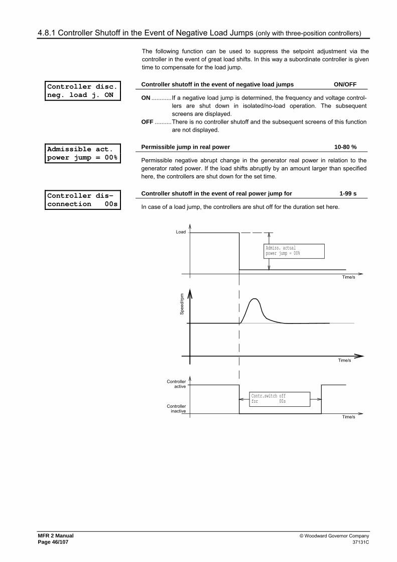
MFR 2 Manual © Woodward Governor Company Page 46/107 37131C
4.8.1 Controller Shutoff in the Event of Negative Load Jumps (only with three-position controllers)
The following function can be used to suppress the setpoint adjustment via the controller in the event of great load shifts. In this way a subordinate controller is given time to compensate for the load jump.
Controller disc. neg. load j. ON
Controller shutoff in the event of negative load jumps ON/OFF
ON ............If a negative load jump is determined, the frequency and voltage control-lers are shut down in isolated/no-load operation. The subsequent screens are displayed.
OFF ..........There is no controller shutoff and the subsequent screens of this function are not displayed.
Admissible act. power jump = 00%
Permissible jump in real power 10-80 %
Permissible negative abrupt change in the generator real power in relation to the generator rated power. If the load shifts abruptly by an amount larger than specified here, the controllers are shut down for the set time.
Controller dis- connection 00s
Controller shutoff in the event of real power jump for 1-99 s
In case of a load jump, the controllers are shut off for the duration set here.
Contr.switch offfor 00s
Load
Admiss. actualpower jump = 00%
Controlleractive
Spee
d/rp
m
Time/s
Time/s
Time/s
Controllerinactive

© Woodward Governor Company MFR 2 Manual 37131C Page 47/107
4.8.2 Shut-Down
Download and open GCB ON
Stoppage ON/OFF
ON ............The generator is stopped when "Enable GCB" is removed. That means that an automatic power reduction and subsequently the opening of the GCB via activation of the relay "Command: open GCB“. If the unit is involved in a load sharing, this is terminated.
OFF ..........The removal of the command "Enable GCB" during the operation has no effect.
4.8.3 No-Load Control
Controll in no- load oper. ON
Automatic no-load control ON/OFF
ON ............The control of voltage and frequency in no-load operation is carried out independent of the state of the command "Enable GCB" (terminal 3) (see also chapter 2.4 "Operating Conditions" starting on page 22).
OFF ..........Additional condition for a control of voltage and frequency in no-load operation is the setting of "Enable GCB" (terminal 3). Take care that by setting terminal 3 the synchronization for the GCB is also enabled (see also chapter 2.4 "Operating Conditions" starting on page 22).
4.8.4 Frequency Controller
a.) Three-Step Controller (Standard)
Freq. controller ON
Frequency controller ON/OFF
ON ............The generator frequency is controlled. The generator frequency is controlled in various manners depending on the task (isolated operation / synchronization). The subsequent screens of this function are displayed.
OFF ..........There is no control, and the subsequent masks of this function are not displayed.
Generator freq. f set = 00.0Hz
Generator setpoint frequency 48.0-62.0 Hz
The generator setpoint frequency is entered here. This is required for the frequency controller in isolated and no-load operation.
Freq. controller Insens. = 0.00Hz
Insensitivity frequency controller 0.02-1.00 Hz
Through the relays "raise/lower" the three-position controller outputs actuating pulses as long as the system deviation is higher than the pre-set insensitivity. The control deviation in the "No-load controlling" operating state is the deviation of the generator actual frequency from the generator setpoint frequency, and in the "synchronization" operating state is the deviation of the generator/busbar frequencies or busbar/mains frequencies.

MFR 2 Manual © Woodward Governor Company Page 48/107 37131C
Freq. controller Time pulse>000ms
Minimum frequency controller On period 10-250 ms
The minimum ON period of the relay should be selected in such a manner that the downstream adjustment facility responds reliably to the pulse that corresponds to the set time. The smallest possible time must be set in order to ensure optimum control behavior.
Freq. controller Gain Kp=00.0
Frequency controller gain 0.1-99.9
The amplification factor Kp affects the turn-on time of the relay. By increasing the factor, the operating time can be increased in the event of a certain control deviation.
b.) Analog Controller Output (Option Qf - Instead of Three-Step Controller)
Freq. controller ON
Frequency controller ON/OFF
ON ............The generator frequency is controlled. The generator frequency is controlled in various manners depending on the task (isolated opera-tion / synchronization). The subsequent screens of this function are displayed.
OFF ..........There is no control, and the subsequent masks of this function are not displayed.
Generator freq. f set = 00.0Hz
Generator setpoint frequency 48.0-62.0 Hz
The generator setpoint frequency is entered here. This is required for the frequency controller in isolated and no-load operation.
Starting point Freq. 000%
Initial setting frequency controller 0-100 %
Setting of the analog controller output when the controller is switched off. This value also is referred to as an initial value, for instance when changing from an real load controller to a frequency controller.
Pr.-sensitivity Freq. Kpr=000
P gain frequency controller 1-240
The proportional coefficient specifies the gain (see analog controller).
Reset time Freq. Tn=00.0s
Reset time frequency controller 0.0-60.0 s
The reset time Tn marks the I-share of the PID-controller (see analog controller).
Derivative act. time(freq) 0.00s
Derivative-action time frequency controller 0.00-6.00 s
The derivative-action time TV marks the D-share of the PID-controller (see analog controller).
Freq. controller logic positive
Logic for the frequency controller positive/negative
positive ......If the actual value of the frequency is lower than the frequency setpoint value, the frequency controller increases the actuating signal.
negative .....If the actual value of the frequency is lower than the frequency setpoint value, the frequency controller decreases the actuating signal.
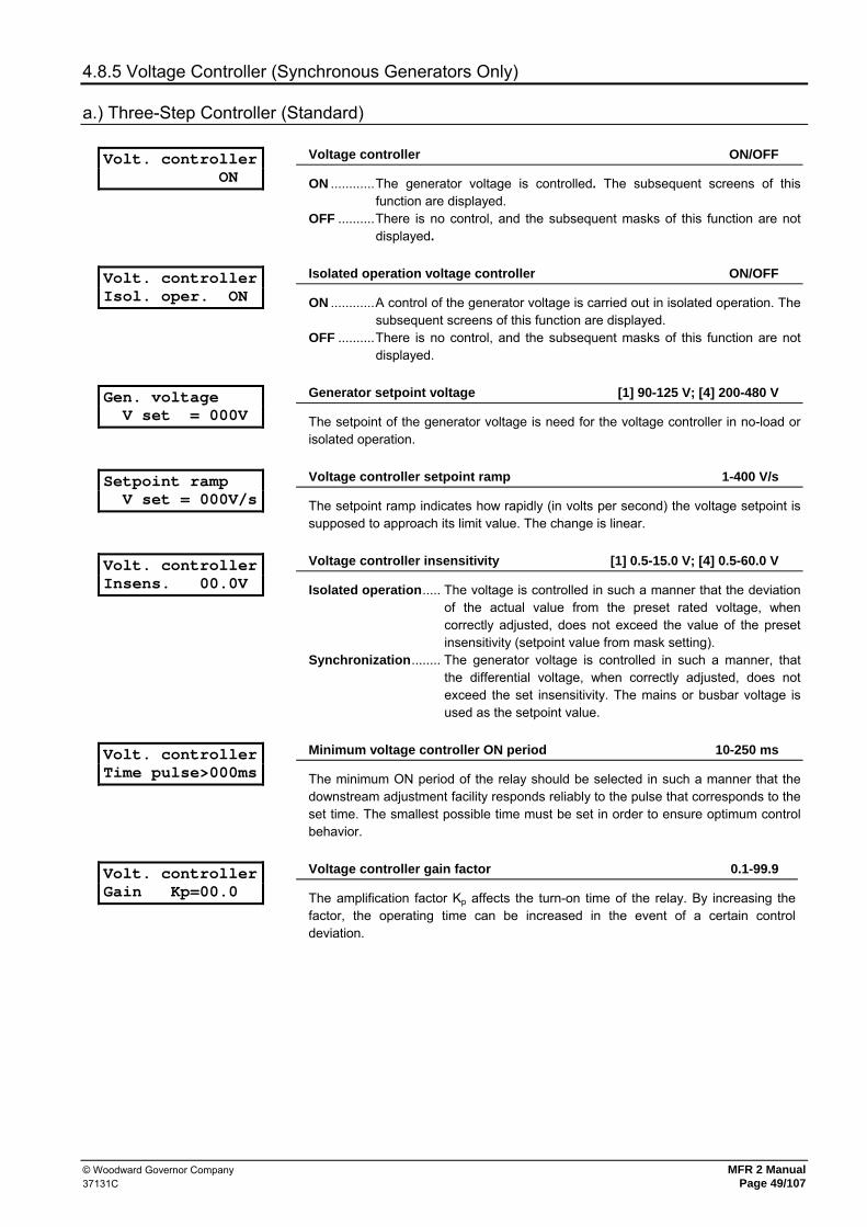
© Woodward Governor Company MFR 2 Manual 37131C Page 49/107
4.8.5 Voltage Controller (Synchronous Generators Only)
a.) Three-Step Controller (Standard)
Volt. controller ON
Voltage controller ON/OFF
ON ............The generator voltage is controlled. The subsequent screens of this function are displayed.
OFF ..........There is no control, and the subsequent masks of this function are not displayed.
Volt. controller Isol. oper. ON
Isolated operation voltage controller ON/OFF
ON ............A control of the generator voltage is carried out in isolated operation. The subsequent screens of this function are displayed.
OFF ..........There is no control, and the subsequent masks of this function are not displayed.
Gen. voltage V set = 000V
Generator setpoint voltage [1] 90-125 V; [4] 200-480 V
The setpoint of the generator voltage is need for the voltage controller in no-load or isolated operation.
Setpoint ramp V set = 000V/s
Voltage controller setpoint ramp 1-400 V/s
The setpoint ramp indicates how rapidly (in volts per second) the voltage setpoint is supposed to approach its limit value. The change is linear.
Volt. controller Insens. 00.0V
Voltage controller insensitivity [1] 0.5-15.0 V; [4] 0.5-60.0 V
Isolated operation..... The voltage is controlled in such a manner that the deviation of the actual value from the preset rated voltage, when correctly adjusted, does not exceed the value of the preset insensitivity (setpoint value from mask setting).
Synchronization........ The generator voltage is controlled in such a manner, that the differential voltage, when correctly adjusted, does not exceed the set insensitivity. The mains or busbar voltage is used as the setpoint value.
Volt. controller Time pulse>000ms
Minimum voltage controller ON period 10-250 ms
The minimum ON period of the relay should be selected in such a manner that the downstream adjustment facility responds reliably to the pulse that corresponds to the set time. The smallest possible time must be set in order to ensure optimum control behavior.
Volt. controller Gain Kp=00.0
Voltage controller gain factor 0.1-99.9
The amplification factor Kp affects the turn-on time of the relay. By increasing the factor, the operating time can be increased in the event of a certain control deviation.

MFR 2 Manual © Woodward Governor Company Page 50/107 37131C
b.) Analog Controller Output (Option Qu - Instead of Three-Step Controller)
Volt. controller ON
Voltage controller ON/OFF
ON ............The generator frequency is controlled. The subsequent screens of this function are displayed.
OFF ..........There is no control, and the subsequent masks of this function are not displayed.
Volt. controller Isol. oper. ON
Voltage controller isolated operation ON/OFF
ON ............A control of the generator voltage is carried out in isolated operation. The subsequent screens of this function are displayed.
OFF ..........There is no control, and the subsequent masks of this function are not displayed.
Gen. voltage V set = 000V
Generator setpoint voltage [1] 90-125 V; [4] 200-480 V
The setpoint of the generator voltage is needed for the voltage controller in no-load and isolated operation.
Setpoint ramp V set = 000V/s
Voltage controller setpoint ramp 1-400 V/s
The setpoint ramp indicates how rapidly (in volts per second) the voltage setpoint is supposed to approach its limit value. The change is linear.
Starting point Voltage =000%
Voltage controller initial setting 0-100 %
Setting of the analog controller output when the controller is switched off. This value also is referred to as an initial value, for instance when changing from a power factor cosphi to a voltage controller.
Pr.-sensitivity Volt. Kpr=000
P gain voltage controller 1-240
The proportional coefficient specifies the gain (see analog controller).
Reset time Volt. Tn=00.0s
Voltage controller reset time 0.0-60.0 s
The reset time Tn marks the I-share of the PID-controller (see analog controller).
Derivative act. time(volt) 0.00s
Derivative-action time voltage controller 0.00-6.00 s
The derivative-action time Tn marks the D-share of the PID-controller (see analog controller).
Volt. controller logic positive
Logic for the voltage controller positive/negative
positive ......If the actual value of the voltage is lower than the setpoint value, the voltage controller increases the actuating signal.
negative .....If the actual value of the voltage is lower than the setpoint value, the voltage controller decreases the actuating signal.

© Woodward Governor Company MFR 2 Manual 37131C Page 51/107
4.8.6 Synchronization (Synchronous Generators Only)
Synchronization functions ON
Synchronization functions ON/OFF
ON ............A synchronization of the generator frequency and voltage is being carried out for the GCB as well as for the MCB. The connect command for the particular power circuit breaker is made with a low positive slip. The subsequent screens of this function are displayed.
OFF ..........No synchronization is carried out, and the subsequent screens are not displayed.
Synchronization df max = 0.00Hz
Max. perm. differential frequency for synchron. (pos. slip) 0.02-0.49 Hz
The prerequisite of a connect command's being output is negative deviation from this set differential frequency. This value indicates the upper frequency (positive value corresponding to positive slip generator frequency higher than busbar frequency during synchronization of GCB; busbar frequency higher than mains frequency during synchronization MCB).
Synchronization df min=- 0.00Hz
Max. perm. differential frequency for synchron. (neg. slip) 0.00--0.49 Hz
A required condition for the output of an add-on order is that the pre-set differential frequency is exceeded. This value indicates the upper frequency (negative value corresponding to positive slip generator frequency less than busbar frequency during synchronization of GCB; busbar frequency less than mains frequency during synchronization MCB).
Synchronization dU max = 00V
Max. perm. differential voltage for synchronization [1] 1-20 V; [4] 2-60 V
To ensure that a connect command will be issued, the actual value must fall below the entered differential voltage.
Synchronization Time pulse>000ms
Min. pulse duration connection relay synchronization 50-250 ms
The duration of the connect impulse can be adjusted to the subordinate switching unit. The time set here shall apply for the connection pulse of the GCB and for that of the MCB.
Gen. circuit br. Pick-up t.=000ms
Inherent delay of GCB 40-300 ms
The pickup time of the GCB corresponds to the lead time of the connect command. The add-on order is output at the pre-set time, before the synchronous point is reached.
Gen. circuit br. Cont. pulse ON
Continuous pulse output for the GCB ON/OFF
ON ............The relay "Command: close GCB" can be looped directly into the self-holding circuit of the power circuit breaker. After the connect command has been output and with a successfully executed reply, the relay "Command: close GCB" remains picked up. If the power circuit breaker has to be opened, the relay drops out.
OFF ..........The relay "Command: close GCB" remains picked up only for the set pulse duration. Generator power circuit breaker self-holding must be carried out via an external self-holding circuit.
Mains circuit br Pick-up t.=000ms
Inherent delay of MCB 40-300 ms
The pickup time of the MCB corresponds to the lead time of the connect command. The add-on order is output at the pre-set time, before the synchronous point is reached.
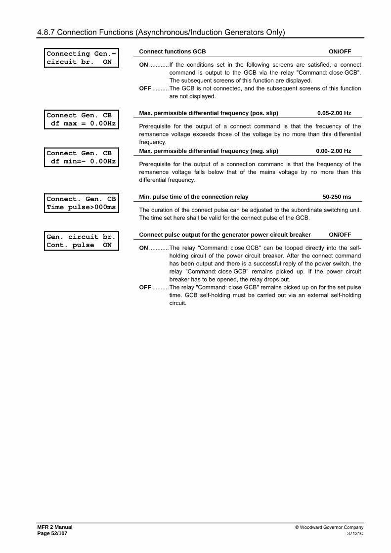
MFR 2 Manual © Woodward Governor Company Page 52/107 37131C
4.8.7 Connection Functions (Asynchronous/Induction Generators Only)
Connecting Gen.- circuit br. ON
Connect functions GCB ON/OFF
ON ............If the conditions set in the following screens are satisfied, a connect command is output to the GCB via the relay "Command: close GCB". The subsequent screens of this function are displayed.
OFF ..........The GCB is not connected, and the subsequent screens of this function are not displayed.
Connect Gen. CB df max = 0.00Hz
Max. permissible differential frequency (pos. slip) 0.05-2.00 Hz
Prerequisite for the output of a connect command is that the frequency of the remanence voltage exceeds those of the voltage by no more than this differential frequency.
Connect Gen. CB df min=- 0.00Hz
Max. permissible differential frequency (neg. slip) 0.00--2.00 Hz
Prerequisite for the output of a connection command is that the frequency of the remanence voltage falls below that of the mains voltage by no more than this differential frequency.
Connect. Gen. CB Time pulse>000ms
Min. pulse time of the connection relay 50-250 ms
The duration of the connect pulse can be adjusted to the subordinate switching unit. The time set here shall be valid for the connect pulse of the GCB.
Gen. circuit br. Cont. pulse ON
Connect pulse output for the generator power circuit breaker ON/OFF
ON ............The relay "Command: close GCB" can be looped directly into the self-holding circuit of the power circuit breaker. After the connect command has been output and there is a successful reply of the power switch, the relay "Command: close GCB" remains picked up. If the power circuit breaker has to be opened, the relay drops out.
OFF ..........The relay "Command: close GCB" remains picked up on for the set pulse time. GCB self-holding must be carried out via an external self-holding circuit.

© Woodward Governor Company MFR 2 Manual 37131C Page 53/107
4.8.8 Dead Bus Operation (Synchronous Generators Only)
If the busbar is in a de-energized state, the direct connection (dead bus operation) of the GCB or the MCB may be carried out. If both connect commands are issued simultaneously, priority is given to the MCB. If several MFR 2 were connected via a CAN bus, a dead bus operation blocking is active, so that only the unit with the lowest generator number gets an add-on pulse.
Gen. circuit br. Dead bus op. ON
Dead bus operation of GCB ON/OFF
ON ............In case of a dead busbar or an open MCB, a dead bus operation is carried out. The prerequisite of this is the detection of an operating condition which corresponds to the specifications. The subsequent screens of this function are displayed.
OFF ..........A dead bus operation is not effected, and the subsequent masks of this function are not displayed.
Dead bus op. GCB df max = 0.00Hz
Max. differential frequency for dead bus operation 0.05-0.90 Hz
The prerequisite of the output of the connect command is that the generator frequency may, at most, deviate from the setpoint by the set value.
Dead bus op. GCB dU max = 00V
Max. differential voltage for dead bus operation [1] 1-20 V; [4] 2-60 V
The prerequisite of the output of the connect command is that the generator voltage may, at most, deviate from the setpoint by the set value.
Mains circuit br Dead bus op. ON
Dead bus operation of MCB ON/OFF
ON ............In case of a dead busbar or an open GCB, a dead bus operation is carried out. The prerequisite of this is the detection of an operating condition which corresponds to the specifications. The subsequent screens of this function are displayed.
OFF ..........A dead bus operation is not effected, and the subsequent masks of this function are not displayed.
4.8.9 Synchronizing Time Monitoring (Synchronous Generators Only)
Sync.time contr. ON
Monitoring of synchronization time ON/OFF
ON ............The synchronization is time monitored. At the beginning of the synchro-nization process, a timer is started. If, following the expiration of the time set below, the power circuit breaker has not closed, a warning message "Synch. time monitoring" is output. The time monitoring applies for the synchronization of both the GCB and the MCB. The subsequent screen is displayed.
OFF ..........Monitoring is not carried out, and the subsequent screen is not displayed.
Sync.time contr. Delay time 000s
Final value for time monitoring 10-999 s
If a synchronization of the generator is started, the counter is started simultaneously. If the power circuit breaker is not closed after the pre-set time, a warning is released "Synchr. time monit.".
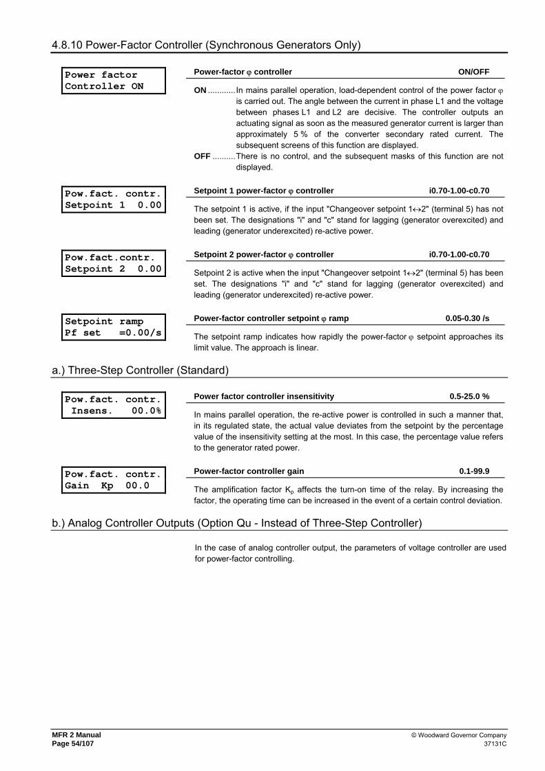
MFR 2 Manual © Woodward Governor Company Page 54/107 37131C
4.8.10 Power-Factor Controller (Synchronous Generators Only)
Power factor Controller ON
Power-factor ϕ controller ON/OFF
ON ............In mains parallel operation, load-dependent control of the power factor ϕ is carried out. The angle between the current in phase L1 and the voltage between phases L1 and L2 are decisive. The controller outputs an actuating signal as soon as the measured generator current is larger than approximately 5 % of the converter secondary rated current. The subsequent screens of this function are displayed.
OFF ..........There is no control, and the subsequent masks of this function are not displayed.
Pow.fact. contr. Setpoint 1 0.00
Setpoint 1 power-factor ϕ controller i0.70-1.00-c0.70
The setpoint 1 is active, if the input "Changeover setpoint 1↔2" (terminal 5) has not been set. The designations "i" and "c" stand for lagging (generator overexcited) and leading (generator underexcited) re-active power.
Pow.fact.contr. Setpoint 2 0.00
Setpoint 2 power-factor ϕ controller i0.70-1.00-c0.70
Setpoint 2 is active when the input "Changeover setpoint 1↔2" (terminal 5) has been set. The designations "i" and "c" stand for lagging (generator overexcited) and leading (generator underexcited) re-active power.
Setpoint ramp Pf set =0.00/s
Power-factor controller setpoint ϕ ramp 0.05-0.30 /s
The setpoint ramp indicates how rapidly the power-factor ϕ setpoint approaches its limit value. The approach is linear.
a.) Three-Step Controller (Standard)
Pow.fact. contr. Insens. 00.0%
Power factor controller insensitivity 0.5-25.0 %
In mains parallel operation, the re-active power is controlled in such a manner that, in its regulated state, the actual value deviates from the setpoint by the percentage value of the insensitivity setting at the most. In this case, the percentage value refers to the generator rated power.
Pow.fact. contr. Gain Kp 00.0
Power-factor controller gain 0.1-99.9
The amplification factor Kp affects the turn-on time of the relay. By increasing the factor, the operating time can be increased in the event of a certain control deviation.
b.) Analog Controller Outputs (Option Qu - Instead of Three-Step Controller)
In the case of analog controller output, the parameters of voltage controller are used for power-factor controlling.

© Woodward Governor Company MFR 2 Manual 37131C Page 55/107
c.) Setpoint Specification - Specified Via Analog Input 0/4-20 mA (Option Xc)
Set Value extern PowFacCon. ON
Power-factor controller external setpoint specification ON/OFF
ON ............Es the power-factor setpoint 2 may be specified via an external signal. The subsequent screens of this function are displayed. This setpoint is active if the input "Changeover setpoint 1↔2" (terminal 5) has been set.
OFF ..........If this function is set to "OFF", external setpoint value specification cannot be carried out via the 0/4-20 mA input. The subsequent two screens of this function are not displayed.
Analog input 0/4-20mA
Power factor setpoint value specification analog input 0-20 / 4-20 mA
The analog input of the power-factor controller (terminals 73/74) can be switched here between 0-20 mA and 4-20 mA depending on the setpoint source. 0-20 mA......Minimum value of the setpoint at 0 mA; maximum value at 20 mA. 4-20 mA......Minimum value of the setpoint at 4 mA; maximum value at 20 mA. A
wire break control is carried out. If the signal falls under the value of 2 mA the constant set value is used for control.
Analog input 0/4mA = 0.00
Minimum value scaling i0.70-1.00-c0.70
The minimum value of the setpoint is defined here.
Analog input 20mA = 0.00
Maximum value scaling i0.00-1.00-c0.00
The maximum value of the setpoint is defined here.
d.) Setpoint Specification - Specification Via Interface (Option Sb/Sf)
Preconditions for a setpoint specification via the interface are: - "Setpoint 2" must be activated via the discrete input (terminal 5) and - the data transmission must be developed. If a data transmission can be developed (the interface was deactivated via the confi-guration screen or there is an interface fault), "Setpoint 2" is adjusted.
4.8.11 Real-Power Controller
Power controller ON
Real-power controller ON/OFF
ON ............When the real-power controller is turned on, the real power is adjusted to the pre-selected setpoint in mains-parallel operation. The subsequent screens of this function are displayed.
OFF ..........There is no control, and the subsequent masks of this function are not displayed.
Power controller Ramp = 000%/s
Setpoint ramp real-power controller 1-100 %/s
A change of the setpoint is transferred to the controller via a ramp. The slope of the ramp changes the speed the controller uses to change the setpoint. The higher the value entered here, the faster the setpoint is changed.
Power limitation P max.= 000 %
Real-power controller maximum power limitation 10-120 %
If the maximum real generator load is to be limited, a percentage, based on the rated generator power, will be entered in this screen. The controller adjusts the unit in such a manner that this value is not exceeded.

MFR 2 Manual © Woodward Governor Company Page 56/107 37131C
NOTE
For the set value power control the transfer point to the mains is not considered, which means that, in the event of excess power, power is exported to the mains, whereas, in the event of a power deficit, the power difference is imported from the mains.
Power controller P set1 = 00000kW
Setpoint 1 generator real power 0-32,000 kW
The setpoint 1 is active when the input "Changeover setpoint 1↔2" (terminal 5) is not set.
Power controller Pset2 = 00000kW
Setpoint 2 Generator real power 0-32,000 kW
The setpoint 2 is active if the input "Changeover setpoint 1↔2" (terminal 5) is set.
a.) Setpoint Specification - Specification Via Analog Input 0/4-20 mA (PSVA & Option X)
Set value extern PowContr ON
Real-power controller external setpoint specification ON/OFF
ON ............The real load setpoint 2 can be preset via an external signal. The subsequent screens of this function are displayed. This setpoint is active, if the input "Changeover setpoint 1↔2" (terminal 5) is set.
OFF ..........If this function is set to "OFF", external setpoint value specification cannot be carried out via the 0/4-20 mA input. The subsequent two screens of this function are not displayed.
Analog input 0/4-20mA
Setpoint value specification analog input 0-20 / 4-20 mA
The analog input of the real power controller (terminals 70/71) can be switched over here between 0-20 mA and 4-20 mA. 0-20 mA......Minimum value of the setpoint at 0 mA; maximum value at 20 mA. 4-20 mA......Minimum value of the setpoint at 4 mA; maximum value at 20 mA. A
wire break control is carried out. If the signal falls under the value of 2 mA the constant set value is used for control.
Analog input 0/4mA = 00000kW
Scaling the minimum value [1] 0-32,000 kW; [4] 0-6,900 kW
The minimum value of the setpoint is defined here.
Analog input 20mA = 00000kW
Scaling the maximum value [1] 0-32,000 kW; [4] 0-6,900 kW
The maximum value of the setpoint is defined here.
b.) Setpoint Specification - Specification Via Interface (PSVA & Option Sb/Sf)
Prerequisites for a setpoint specification via the interface are: - "Setpoint 2" must be activated via the discrete input (terminal 5) and - the data transmission must be developed. If no data transmission can be developed (the interface was deactivated via the configuration screen or an interface fault is present), "Setpoint 2" is adjusted.

© Woodward Governor Company MFR 2 Manual 37131C Page 57/107
c.) Three-Step Controller (Standard)
Power controller Insens. = 00.0%
Insensitivity real load controller 0.1-25.0 %
In mains parallel operation, the real power is controlled in such a manner that, in its regulated state, the actual value deviates from the power setpoint by the percentage value of the sensitivity setting at the most. In this case, the percentage value refers to the generator rated power.
Power controller Gain Kp= 00.0
Real power controller gain factor 0.1-99.9
The amplification factor Kp affects the turn-on time of the relay. By increasing the factor, the operating time can be increased in the event of a certain control deviation.
Power controller Sens.red. *0.0
Real power controller sensitivity reduction 1.0-9.9
If no further adjusting pulse has been output for at least 5 s the insensitivity is reduced by the input factor. For example: In case of an insensitivity of 2.5 % and a factor 2.0, insensitivity is increased to 5.0 % after 5 s. In the event that the system deviation then exceeds 5.0 % again, the governor automatically goes back to its original sensitivity (2.5 %). This input can be used, in the event of small control deviations, to avoid unnecessarily frequent actuation processes, thereby protecting the adjustment facility.
d.) Analog Controller Outputs (Option Qf - Instead of Three-Step Controller)
Power controller Gain Kpr 000
Real-power controller P gain 1-240
The proportional coefficient specifies the gain (see analog controller).
Reset time Power Tn=00.0s
Real-power controller reset time 0.0-60.0 s
The reset time Tn marks the I-share of the PID-controller (see analog controller).
Derivative act. time(pow.) 0.00s
Real-power controller derivative-action time 0.0-6.0 s
The derivative-action time TV marks the D-share of the PID-controller (see analog controller).

MFR 2 Manual © Woodward Governor Company Page 58/107 37131C
e.) Part-Load Lead
Part-load lead ON
Part-load lead ON/OFF
ON ............Part-load lead is carried out, and the subsequent screens of this function are displayed. If the genset needs a warmup phase, the power setpoint value can hereby be limited to the part-load value to be entered below after synchronization with the mains parallel operation.
OFF ..........No part-load lead is carried out and the subsequent screens of this function are not displayed.
Part load lead Setpoint = 000 %
Part-load lead limit value 5-110 %
After synchronization, the generator power is limited to the part-load value set here.
Part-load lead Time 000s
Period of part-load lead 0-600 s
Input of the holding time with part-load following initial closure of the power circuit breaker in mains parallel operation.
4.8.12 Load and/or Var Sharing
Active power load-share ON
Load sharing ON/OFF
ON ............Real power is distributed to several generators operating in parallel. The generator outputs are distributed depending on the set value. The subsequent screens of this function are displayed (see also chapter 2.7 "Load/Var" starting from page 29).
OFF ..........There is no control, and the subsequent masks of this function are not displayed.
Act. load share factor =00%
Load sharing reference variable 10-99 %
Increasing the weighting factor increases the influence of the main control variable (in isolated operation: Frequency, in mains operation: real power) on control. The smaller the factor which is set, the greater the influence of the secondary control variable (generator real power). The behavior of frequency control (isolated operation) is determined by the main control variable, that of real power distribution by the secondary control variable.
Reactive power load-share ON
(only sychronous generators)
var sharing ON/OFF
ON ............Re-active power is distributed to several generators operating in parallel. The generator outputs are distributed depending on the set value. The subsequent screens of this function are displayed (see also chapter 2.7 "Load/Var" starting from 29).
OFF ..........There is no control, and the subsequent masks of this function are not displayed.
React.load share factor =00%
(only synchronous generators)
var sharing reference variable 10-99 %
Increasing the weighting factor increases the influence of the main control variable (in isolated operation: Voltage, in mains parallel operation: re-active power) on control. The smaller the factor which is set, the greater the influence of the secondary control variable (generator re-active power). The behavior of voltage control (isolated operation) is determined by the main control variable, that of re-active power distribution by the secondary control variable.
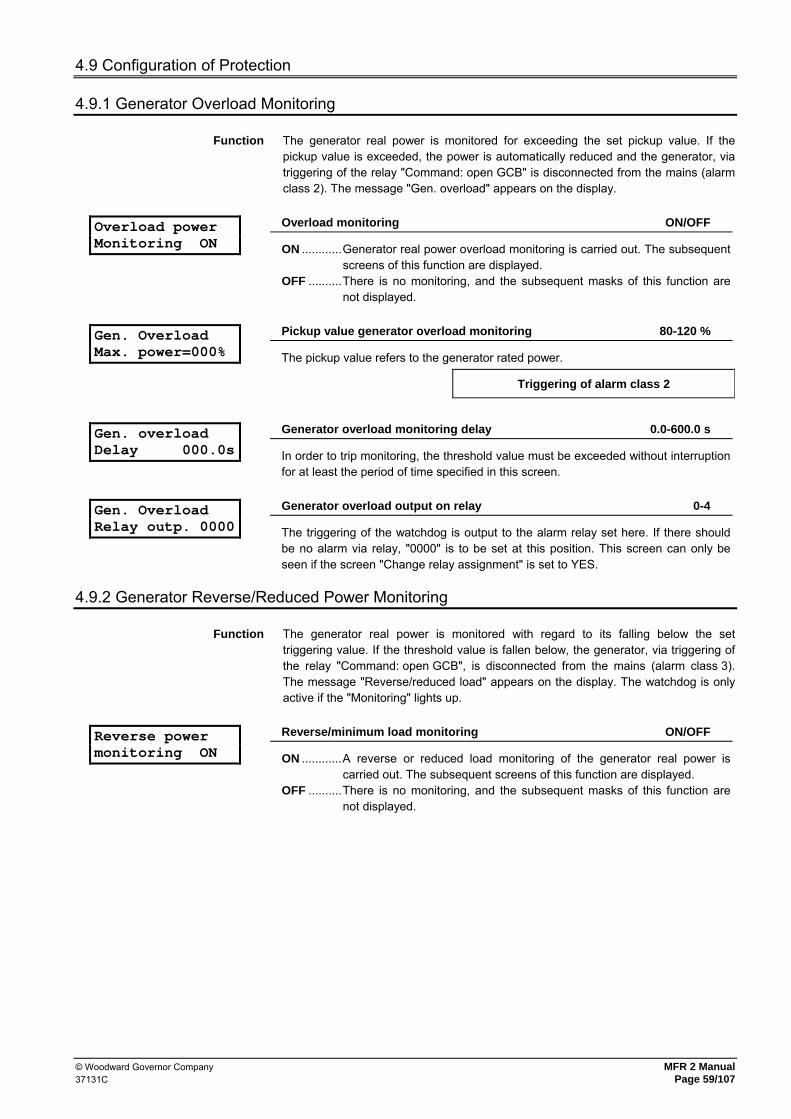
© Woodward Governor Company MFR 2 Manual 37131C Page 59/107
4.9 Configuration of Protection
4.9.1 Generator Overload Monitoring
Function The generator real power is monitored for exceeding the set pickup value. If the pickup value is exceeded, the power is automatically reduced and the generator, via triggering of the relay "Command: open GCB" is disconnected from the mains (alarm class 2). The message "Gen. overload" appears on the display.
Overload power Monitoring ON
Overload monitoring ON/OFF
ON ............Generator real power overload monitoring is carried out. The subsequent screens of this function are displayed.
OFF ..........There is no monitoring, and the subsequent masks of this function are not displayed.
Gen. Overload Max. power=000%
Pickup value generator overload monitoring 80-120 %
The pickup value refers to the generator rated power.
Triggering of alarm class 2
Gen. overload Delay 000.0s
Generator overload monitoring delay 0.0-600.0 s
In order to trip monitoring, the threshold value must be exceeded without interruption for at least the period of time specified in this screen.
Gen. Overload Relay outp. 0000
Generator overload output on relay 0-4
The triggering of the watchdog is output to the alarm relay set here. If there should be no alarm via relay, "0000" is to be set at this position. This screen can only be seen if the screen "Change relay assignment" is set to YES.
4.9.2 Generator Reverse/Reduced Power Monitoring
Function The generator real power is monitored with regard to its falling below the set triggering value. If the threshold value is fallen below, the generator, via triggering of the relay "Command: open GCB", is disconnected from the mains (alarm class 3). The message "Reverse/reduced load" appears on the display. The watchdog is only active if the "Monitoring" lights up.
Reverse power monitoring ON
Reverse/minimum load monitoring ON/OFF
ON ............A reverse or reduced load monitoring of the generator real power is carried out. The subsequent screens of this function are displayed.
OFF ..........There is no monitoring, and the subsequent masks of this function are not displayed.

MFR 2 Manual © Woodward Governor Company Page 60/107 37131C
Reverse power Threshold = 00%
Reverse/reduced power monitoring threshold value -99-0-+99 %
The threshold value refers to the input rated power of the generator. Reduced power monitoring ...... Tripping, if the real load falls below the (positive)
limiting value. Reverse load monitoring........... triggering, if the direction of the real power is
reversed and the (negative) limit value is fallen below.
Triggering of alarm class 3
Reverse power Delay 00.0s
Delay of reverse/minimum load monitoring 0.1-99.9 s
In order for tripping to occur, negative deviation from the threshold value must occur without interruption for at least the period of time specified in this screen.
Reverse power Relay outp.0000
Output reverse/reduced load on relay 0-4
The triggering of the watchdog is output on the alarm relay set here. Should no signal occur via relay, "0000" is to be set in this position. This screen can only be seen if the screen "Change relay assignment" is set to YES.
4.9.3 Unbalanced Load Monitoring
Function The unbalanced load watchdog monitors the individual currents of the generator on a percentage deviation from the arithmetic means of all generator currents. If an unbalanced load is detected, the generator, via triggering of the relay "Command: open GCB", is disconnected from the mains (alarm class 3). The message "Load imbalance" appears on the display.
Load unbalance Monitoring ON
Unbalanced load monitoring ON/OFF
ON ............The generator unbalanced load is monitored. The subsequent screens of this function are displayed.
OFF ..........There is no monitoring, and the subsequent masks of this function are not displayed.
Load unbalance Threshold =000%
Maximum permissible unbalanced load 0-100 %
Monitoring of the set maximum unbalanced load is carried out in reference to the generator rated current which has been set.
Tripping of alarm class 3
Load unbalance Delay =00.00s
Unbalanced load monitoring delay 0.04-99.98 s
In order to trip monitoring, the threshold value must be exceeded without interruption for at least the period of time specified in this screen.
Load unbalance Relay outp.0000
Signal unbalanced load on relay 0-4
The triggering of the watchdog is output to the alarm relay set here. Should there be no signal via relay, "0000" is to be set in this place. This screen can only be seen if the screen "Change relay assignment" is set to YES.

© Woodward Governor Company MFR 2 Manual 37131C Page 61/107
4.9.4 Definite Time-Overcurrent Protection
Function The individual currents of the generator are monitored with regard to excess. The converter rated current is used as the reference value. The overcurrent watchdog has been configured for two stages and thus offers the possibility of setting the triggering level 1 to a lower triggering value with a relatively long delay time and triggering level 2 to a higher triggering value with a lesser delay (rapid triggering). If the exceeding a value is detected, the generator, via triggering of the relay "Com-mand: open GCB" are disconnected from the mains (alarm class 3). The message "Gen. overcurrent 1", or "Gen. overcurrent 2" appears on the display.
I >>(I )
I >(I )
t2 t1 t [s]
I [%]
1
2
Overcurrent monitoring ON
Overcurrent monitoring ON/OFF
ON ............The generator current is monitored, and the subsequent masks of this function are displayed
OFF ..........There is no monitoring, and the subsequent masks of this function are not displayed.
Overcurrent Thresh 1 =000%
Threshold value generator overcurrent, level 1 0-300 %
If the value of the generator current exceeds the set percentage value in relation to the converter rated current, a shutdown occurs.
Triggering of alarm class 3
Overcurrent Delay 1 00.00s
Delay of the overcurrent monitoring, level 1 0.04-99.98 s
In order to trip monitoring, the threshold value must be exceeded without interruption for at least the period of time specified in this screen.
Overcurrent 1 Relay outp. 0000
Message overcurrent stage 1 to relay 0-4
Triggering of the monitor is output to the alarm relay set here. If no signal is to occur via relay, "0000" is to be set in this position. This screen can only be see if the screen "Change relay assignment" is set to YES.
Overcurrent Thresh 2 =000%
Generator overcurrent threshold value level 2 0-300 %
If the value of the generator current exceeds the set percentage value in relation to the converter rated current, there is a shutdown.
Triggering of alarm class 3

MFR 2 Manual © Woodward Governor Company Page 62/107 37131C
Overcurrent Delay 2 00.00s
Delay of overcurrent monitoring, level 2 0.04-99.98 s
In order to trip monitoring, the threshold value must be exceeded without interruption for at least the period of time specified in this screen.
Overcurrent 2 Relay outp. 0000
Message overcurrent level 2 on relay 0-4
The triggering of the monitor is set to the signal relay set here. If no message is made via relay, "0000" is to be set in this position. This screen can only be seen if the screen "Change relay assignment" is set to YES.
4.9.5 Ground Fault Monitoring (Option I3)
Function The unit can be installed in the stator winding of three-phase machines to detect ground faults. Primarily, in the case of ground faults, the occurrence of a displacement voltage is used for triggering, whereby a protective area up to approximately 95 % of the winding can be achieved. The displacement voltage is typically measured using the open delta winding (e-n-winding) of a voltage converter or using a zero-point transformer in the machine star point. Normally, on these transformers a secondary voltage of 500 V is set in the event of a terminal ground fault so that a voltage splitter is required (Translation 500 V / 100 V). The single-phase parts of the very strong third harmonics occurring with synchronous machines add up such that the fundamental wave can be measured without interference only by using an especially effective digital filtering method. The displacement voltage is monitored with regard to its exceeding the set threshold value. If the threshold value is exceeded, the generator, via triggering of the relay "Command: open GCB", is disconnected from the mains (alarm class 3). The "Ground fault" message appears on the display.
Earth-fault monitoring ON
Ground fault monitoring ON/OFF
ON ............Displacement voltage is monitored. The subsequent screens of this function are displayed.
OFF ..........There is no monitoring, and the subsequent masks of this function are not displayed.
Residual volt. Response v. 000V
Ground fault triggering with a displacement voltage of 1-125 V
If the value of the displacement voltage exceeds the value set here, there is a shutdown.
Triggering of alarm class 3
Residual volt. Delay =00.00s
Delay of ground fault monitoring 0.02-99.98 s
In order to trip monitoring, the threshold value must be exceeded without interruption for at least the period of time specified in this screen.
Residual volt. Relay outp. 0000
Signal ground fault on relay 0-4
The triggering of the watchdog is output on the alarm relay set here. If there is to be no signal via relay, "0000" is to be set in this position. This screen can only be seen if the screen "Change relay assignment" is set to YES.

© Woodward Governor Company MFR 2 Manual 37131C Page 63/107
4.9.6 Re-Active Power Monitoring
Function Re-active power is monitored with regard to its exceeding the set threshold value (leading and lagging). In this case the monitoring of the leading re-active power can be used as field-failure detection. If there is positive deviation from the threshold value, the generator, via triggering of the relay "Command: open GCB", is disconnected from the mains (fault class 3). The message "Reactive power ind." or "Reactive power cap." appears on the display.
a.) Lagging Re-Active Power
Lagg.react.power monitoring ON
Lagging re-active power monitoring ON/OFF
ON ............The lagging re-active power is monitored. OFF ..........There is no monitoring, and the subsequent masks of this function are
not displayed.
Lagg.react.power Threshold 000%
Lagging re-active power monitoring threshold value 0-160 %
If the value of the lagging re-active power exceeds the set percentage value in relation to the generator rated power a shutdown occurs.
Triggering of alarm class 3
Lagg.react.power Delay 00.00s
Lagging re-active power monitoring delay 0.04-99.98 s
In order to trip monitoring, the threshold value must be exceeded without interruption for at least the period of time specified in this screen.
Lagg.react.power Relay outp. 0000
Signal lagging re-active power on relay 0-4
The triggering of the watchdog is output to the alarm relay set here. If no signal is to occur via relay, "0000" is to be set in this position. This screen can only be seen if the screen "Change relay assignment" is set to YES.
b.) Leading Re-Active Power (field failure detection)
Lead.react.power monitoring ON
Leading re-active power monitoring ON/OFF
ON ............The leading re-active power is monitored. OFF ..........There is no monitoring, and the subsequent masks of this function are
not displayed.
Lead.react.power Threshold 000%
Leading re-active power monitoring threshold value 0-160 %
If the value of the leading re-active power exceeds the set percentage value in relation to the generator rated power, there is a shutdown.
Triggering of alarm class 3
Lead.react.power Delay 00.00s
Leading re-active power monitoring delay 0.04-99.98 s
In order to trip monitoring, the threshold value must be exceeded without interruption for at least the period of time specified in this screen.
Lead.react.power Relay outp. 0000
Signal leading re-active power on relay 0-4
The triggering of the watchdog is output to the alarm relay set here. If there is to be no signaling via relay, "0000" is to be set in this position. This screen can only be seen if the screen "Change relay assignment" is set to YES.
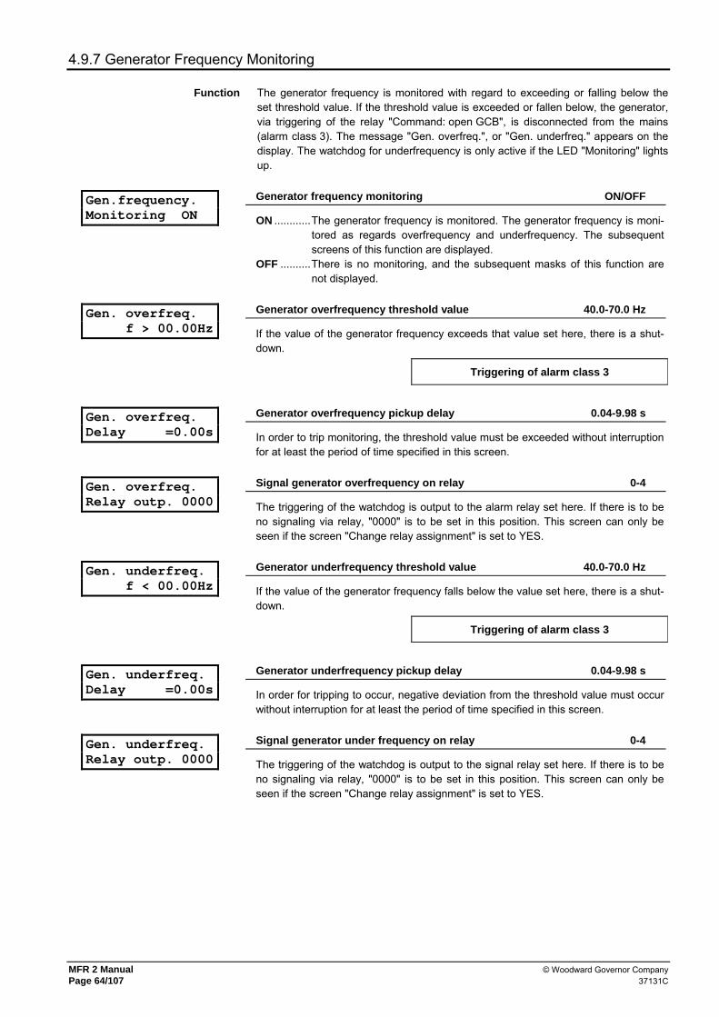
MFR 2 Manual © Woodward Governor Company Page 64/107 37131C
4.9.7 Generator Frequency Monitoring
Function The generator frequency is monitored with regard to exceeding or falling below the set threshold value. If the threshold value is exceeded or fallen below, the generator, via triggering of the relay "Command: open GCB", is disconnected from the mains (alarm class 3). The message "Gen. overfreq.", or "Gen. underfreq." appears on the display. The watchdog for underfrequency is only active if the LED "Monitoring" lights up.
Gen.frequency. Monitoring ON
Generator frequency monitoring ON/OFF
ON ............The generator frequency is monitored. The generator frequency is moni-tored as regards overfrequency and underfrequency. The subsequent screens of this function are displayed.
OFF ..........There is no monitoring, and the subsequent masks of this function are not displayed.
Gen. overfreq. f > 00.00Hz
Generator overfrequency threshold value 40.0-70.0 Hz
If the value of the generator frequency exceeds that value set here, there is a shut-down.
Triggering of alarm class 3
Gen. overfreq. Delay =0.00s
Generator overfrequency pickup delay 0.04-9.98 s
In order to trip monitoring, the threshold value must be exceeded without interruption for at least the period of time specified in this screen.
Gen. overfreq. Relay outp. 0000
Signal generator overfrequency on relay 0-4
The triggering of the watchdog is output to the alarm relay set here. If there is to be no signaling via relay, "0000" is to be set in this position. This screen can only be seen if the screen "Change relay assignment" is set to YES.
Gen. underfreq. f < 00.00Hz
Generator underfrequency threshold value 40.0-70.0 Hz
If the value of the generator frequency falls below the value set here, there is a shut-down.
Triggering of alarm class 3
Gen. underfreq. Delay =0.00s
Generator underfrequency pickup delay 0.04-9.98 s
In order for tripping to occur, negative deviation from the threshold value must occur without interruption for at least the period of time specified in this screen.
Gen. underfreq. Relay outp. 0000
Signal generator under frequency on relay 0-4
The triggering of the watchdog is output to the signal relay set here. If there is to be no signaling via relay, "0000" is to be set in this position. This screen can only be seen if the screen "Change relay assignment" is set to YES.

© Woodward Governor Company MFR 2 Manual 37131C Page 65/107
4.9.8 Generator Voltage Monitoring
Function The delta voltages of the generator are monitored for exceeding or falling below the set threshold value. If the threshold value is exceed or fallen below, the generator, via triggering of the relay "Command: open GCB", is disconnected from the mains (alarm class 3). The message "Gen. overvolt.", or "Gen. undervolt." appears in the display. The watchdog for undervoltage is only active if the LED "Monitoring" lights up.
Gen.voltage Monitoring ON
Generator voltage monitoring ON/OFF
ON ............The generator voltage is monitored. The generator voltage is monitored with regard to overvoltage and undervoltage. The subsequent screens of this function are displayed.
OFF ..........There is no monitoring, and the subsequent masks of this function are not displayed.
Rated voltage Gen. Vn = 000V
Rated generator voltage [1] 50-125 V, [4] 50-480 V
The threshold values for the generator voltage monitoring refer to this rated value. Regardless of the measurement or monitoring, the secondary value of the delta volt-age has to be entered here.
Volt. Monit.Gen. xxxxxxxxxxxxxxxx
Voltage monitoring generator Phase to phase/Phase-neutral
The device can either monitor the phase-neutral voltages or the phase to phase volt-ages. It is usual to monitor the phase-neutral voltages in low voltage mains and phase to phase voltages in medium voltage mains. A monitoring of the phase to phase voltages is necessary in particular if a ground fault shall not trigger the voltage protection in isolated or compensated mains. If the voltage measurement is performed without a neutral line (i.e. parameter volt-age monitoring = phase to phase, chapter Basic Settings on page 44), the setting "phase to phase" must be selected here. Phase to phase..The phase to phase voltages (VL-L) are monitored. Phase-neutral..The phase-neutral voltages (VL-N) are monitored.
Gen.overvolt. V > 000%
Gen. overvoltage threshold value 20-150 %
If the value of the generator voltage exceeds the value set here, there is a shutdown.
Triggering of alarm class 3
Gen. overvolt. Delay =0.00s
Generator overvoltage pickup delay 0.04-9.98 s
In order to trip monitoring, the threshold value must be exceeded without interruption for at least the period of time specified in this screen.
Gen. overvolt. Relay outp. 0000
Signal generator overvoltage on relay 0-4
The triggering of the watchdog is output to the signal relay set here. If there is to be no signaling via relay, "0000" is to be set in this position. This screen can only be seen if the screen "Change relay assignment" is set to YES.

MFR 2 Manual © Woodward Governor Company Page 66/107 37131C
Gen.undervolt. V < 000%
Threshold value gen. undervoltage 20-150 %
If the value of the generator voltage falls below the value set here, there is a shut-down.
Triggering of alarm class 3
Gen. undervolt. Delay =0.00s
Generator undervoltage pickup delay 0.04-9.98 s
In order for tripping to occur, negative deviation from the threshold value must occur without interruption for at least the period of time specified in this screen.
Gen. undervolt. Relay outp. 0000
Signal generator undervoltage on relay 0-4
The triggering of the watchdog is output to the signal relay set here. If there is to be no signaling via relay, "0000" is to be set in this position. This screen can only be seen if the screen "Change relay assignment" is set to YES.
4.9.9 Mains Frequency Monitoring
Function The monitoring of mains frequency is absolutely necessary if a generator is operated within a public network. In case of a mains failure (e.g. short interruption of power supply) the generator working mains parallel must be automatically disconnected from the mains. The mains frequency is monitored with regard to exceeding or falling below the set threshold value. If the threshold value is exceeded or fallen below, the system, via triggering of the relay configured for mains decoupling, is disconnected from the mains (alarm class 0). The message "Mains overfrequency" or "Mains underfrequency" appears on the display.
Mains frequency Monitoring ON
Mains frequency monitoring ON/OFF
ON ............The mains frequency is monitored. The mains frequency is monitored as regards overfrequency and underfrequency. The subsequent screens of this function are displayed.
OFF ..........There is no monitoring, and the subsequent masks of this function are not displayed.
Mains overfreq. f > 00.00Hz
Mains overfrequency threshold value 40.0-70.0 Hz
If the value of the mains frequency exceeds the value set here, there is a mains disconnection.
Triggering of alarm class 0
Mains overfreq. Delay =0.00s
Mains overfrequency pickup delay 0.04-9.98 s
In order to trip monitoring, the threshold value must be exceeded without interruption for at least the period of time specified in this screen.
Mains overfreq. Relay outp. 0000
Signal mains overfrequency on relay 0-4
The triggering of the watchdog is output to the signal relay set here. If there is to be no signaling via relay, "0000" is to be set in this position. This screen can only be seen if the screen "Change relay assignment" is set to YES.

© Woodward Governor Company MFR 2 Manual 37131C Page 67/107
Mains underfreq. f < 00.00Hz
Mains underfrequency threshold value 40.0-70.0 Hz
If the value of the mains frequency falls below the value set here, there is a mains disconnection.
Triggering of alarm class 0
Mains underfreq. Delay time=0.00s
Mains underfrequency pickup delay 0.04-9.98 s
In order for tripping to occur, negative deviation from the threshold value must occur without interruption for at least the period of time specified in this screen.
Mains underfreq. Relay outp. 0000
Signal mains underfrequency on relay 0-4
The triggering of the watchdog is output to the signal relay set here. If there is to be no signaling via relay, "0000" is to be set in this position. This screen can only be seen if the screen "Change relay assignment" is set to YES.
4.9.10 Mains Voltage Monitoring
Function Monitoring the mains voltage is absolutely necessary if a generator is operated within a public network. In case of a mains failure (e.g. short interruption of power supply) the generator working mains parallel must be automatically disconnected from the mains. The delta voltages of the mains are monitored with regard to exceeding or falling below that set threshold value. If the threshold value is exceeded or fallen below, the system, via triggering of the relay configured for mains decoupling, is disconnected from the mains (alarm class 0). The message "Mains overvolt." or "Mains undervolt." appears on the display.
Mains voltage monitoring ON
Mains voltage monitoring ON/OFF
ON ............The mains voltage is monitored. The mains voltage is monitored with regard to overvoltage and undervoltage. The subsequent screens of this function are displayed.
OFF ..........There is no monitoring, and the subsequent masks of this function are not displayed.
Rated voltage Mains Vn = 000V
Rated mains voltage [1] 50-125 V, [4] 50-480 V
The threshold values for the mains voltage monitoring refer to this rated value. Re-gardless of the measurement or monitoring, the secondary value of the delta voltage has to be entered here.
Volt.Monit.mains xxxxxxxxxxxxxxxx
Spannungsüberwachung Netz Drei-/Vierleiternetz
The device can either monitor the phase-neutral voltages or the phase to phase volt-ages. It is usual to monitor the phase-neutral voltages in low voltage mains and phase to phase voltages in medium voltage mains. A monitoring of the phase to phase voltages is necessary in particular if a ground fault shall not trigger the voltage protection in isolated or compensated mains. If the voltage measurement is performed without a neutral line (i.e. parameter volt-age monitoring = phase to phase, chapter Basic Settings on page 44), the setting "phase to phase" must be selected here. Phase to phase..The phase to phase voltages (VL-L) are monitored. Phase-neutral..The phase-neutral voltages (VL-N) are monitored.
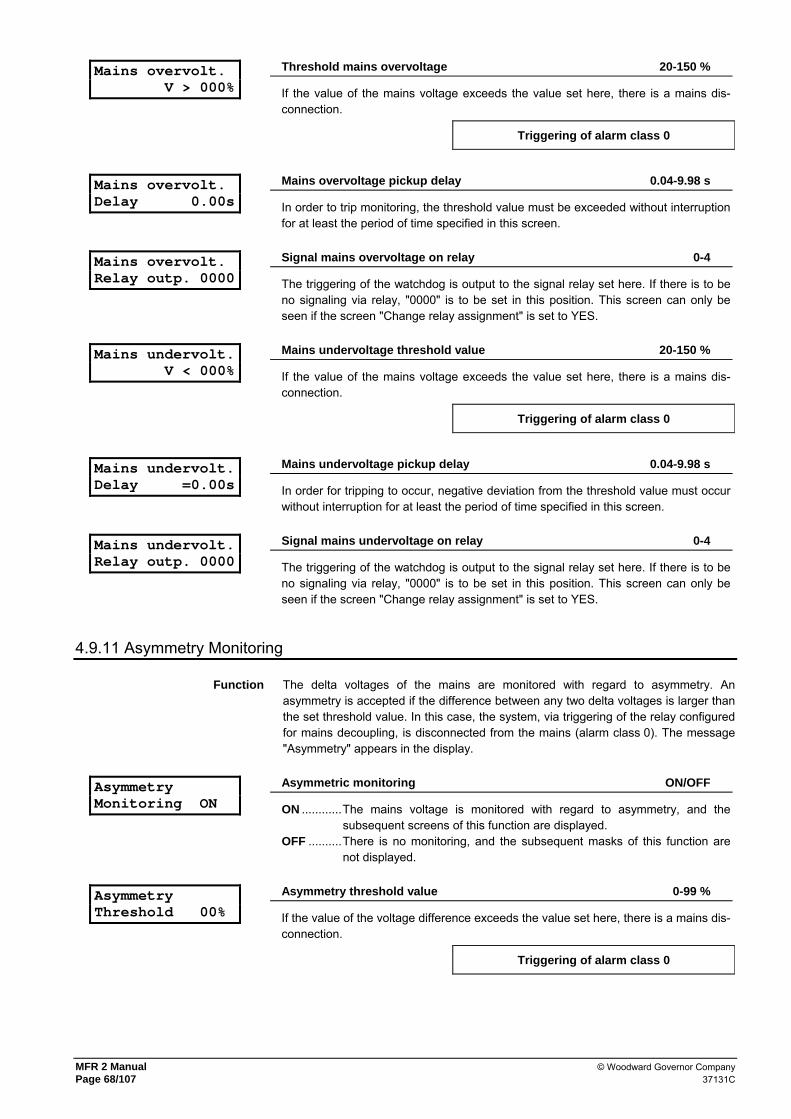
MFR 2 Manual © Woodward Governor Company Page 68/107 37131C
Mains overvolt. V > 000%
Threshold mains overvoltage 20-150 %
If the value of the mains voltage exceeds the value set here, there is a mains dis-connection.
Triggering of alarm class 0
Mains overvolt. Delay 0.00s
Mains overvoltage pickup delay 0.04-9.98 s
In order to trip monitoring, the threshold value must be exceeded without interruption for at least the period of time specified in this screen.
Mains overvolt. Relay outp. 0000
Signal mains overvoltage on relay 0-4
The triggering of the watchdog is output to the signal relay set here. If there is to be no signaling via relay, "0000" is to be set in this position. This screen can only be seen if the screen "Change relay assignment" is set to YES.
Mains undervolt. V < 000%
Mains undervoltage threshold value 20-150 %
If the value of the mains voltage exceeds the value set here, there is a mains dis-connection.
Triggering of alarm class 0
Mains undervolt. Delay =0.00s
Mains undervoltage pickup delay 0.04-9.98 s
In order for tripping to occur, negative deviation from the threshold value must occur without interruption for at least the period of time specified in this screen.
Mains undervolt. Relay outp. 0000
Signal mains undervoltage on relay 0-4
The triggering of the watchdog is output to the signal relay set here. If there is to be no signaling via relay, "0000" is to be set in this position. This screen can only be seen if the screen "Change relay assignment" is set to YES.
4.9.11 Asymmetry Monitoring
Function The delta voltages of the mains are monitored with regard to asymmetry. An asymmetry is accepted if the difference between any two delta voltages is larger than the set threshold value. In this case, the system, via triggering of the relay configured for mains decoupling, is disconnected from the mains (alarm class 0). The message "Asymmetry" appears in the display.
Asymmetry Monitoring ON
Asymmetric monitoring ON/OFF
ON ............The mains voltage is monitored with regard to asymmetry, and the subsequent screens of this function are displayed.
OFF ..........There is no monitoring, and the subsequent masks of this function are not displayed.
Asymmetry Threshold 00%
Asymmetry threshold value 0-99 %
If the value of the voltage difference exceeds the value set here, there is a mains dis-connection.
Triggering of alarm class 0

© Woodward Governor Company MFR 2 Manual 37131C Page 69/107
Asymmetry Delay 00.00s
Pickup delay of the asymmetry monitoring 0.04-99.98 s
In order to trip monitoring, the threshold value must be exceeded without interruption for at least the period of time specified in this screen.
Asymmetry Relay outp. 0000
Signal asymmetry on relay 0-4
The triggering of the watchdog is output to the signal relay set here. If there is to be no signaling via relay, "0000" is to be set in this position. This screen can only be seen if the screen "Change relay assignment" is set to YES.
4.9.12 Phase Shift Monitoring (Synchronous Generators Only)
Function A phase shift is a sudden change in the voltage curve, and may be caused by a major load change. In this case, the unit detects a change in the cycle duration once. This change in the cycle duration is compared with a calculated mean value from previous measurements. The monitoring is carried out in three phases or, alter-natively, even in one phase. The phase shift monitor is only active if the mains voltage is larger than 70 % of the converter rated voltage. If the threshold value is exceeded, the system, via triggering of the relay configured for mains decoupling is separated from the mains (alarm class 0). The message "Phase shift" appears in the display.
Phase shift- Monitoring ON
Phase shift monitoring ON/OFF
ON ............The mains frequency is monitored, and a phase shift is registered within the defined range. The subsequent screens of this function are displayed.
OFF ..........There is no monitoring, and the subsequent masks of this function are not displayed.
Phase jmp monit. one/three phase
Phase shift monitoring one/three-phase / three-phase only
one/three-phase ...During single-phase voltage phase shift monitoring, tripping oc-curs if the phase shift exceeds the specified threshold value in at least one of the three phases. Note: If a phase shift occurs in one or two phases, the single-phase threshold is considered; if a phase shift occurs in all three phases, the three-phase threshold is considered; This type of monitoring is very sensitive, and may lead to false tripping if the selected phase angle settings are too small.
three-phase only ..During three-phase voltage phase shift monitoring, tripping oc-curs only if the phase shift exceeds the specified threshold value in all three phases within 2 cycles.
Triggering of alarm class 0
NOTE
If the monitoring is set to "three-phase only", only the lower of the two subsequent masks is visible; if the monitoring is set to "one/three-phase", both configuration masks are visible.

MFR 2 Manual © Woodward Governor Company Page 70/107 37131C
Phase-jump value (One phase) 00°
This screen is only visible if the monitoring is set to
"one/three-phase".
Maximum phase difference 2-90°
Tripping occurs if the electrical angle of the voltage curve shifts in at least one phase by more than the specified angle.
Phase-jump value (3-phase) 00°
Maximum phase difference 2-90°
Tripping occurs if the electrical angle of the voltage curve shifts in all three phases by more than the specified angle.
Phase-jump value Relay outp. 0000
Signal phase shift on relay 0-4
The triggering of the watchdog is output to the signal relay set here. If there is to be no signaling via relay, "0000" is to be set in this position. This screen can only be seen if the screen "Change relay assignment" is set to YES.
4.9.13 df/dt Monitoring (PSVA & Option D)
Function The unit determines a measuring value for the change in frequency. In order to enable reliable differentiation between phase shift and df/dt, measurement is carried out over 4 cycles. This results in a minimum tripping time of approx. 100 ms. If the threshold value is exceeded, the system, via triggering of the relay configured for mains decoupling, is disconnected from the mains (alarm class 0). The message "Alarm df/dt" appears on the display.
df/dt Monitoring ON
df/dt monitoring ON/OFF
ON ............Mains frequency monitoring is carried out, and any change in frequency per unit of time within the defined range is registered. The subsequent screens of this function are displayed.
OFF ..........There is no monitoring, and the subsequent masks of this function are not displayed.
Release value df/dt > 0.0Hz/s
df/dt monitoring threshold value 1.0-9.9 Hz
If the value of the mains frequency change exceeds the value set here, there is a mains disconnection.
Triggering of alarm class 0
Time delay df/dt T=0.0s
df/dt monitoring triggering delay 0.1-9.9 s
In order to trip monitoring, the threshold value must be exceeded without interruption for at least the period of time specified in this mask.
df/dt monitoring Relay outp. 0000
Signal df/dt monitoring on relay 0-4
The triggering of the watchdog is output to the signal relay set here. If there is to be no signaling via relay, "0000" is to be set in this position. This screen can only be seen if the screen "Change relay assignment" is set to YES.

© Woodward Governor Company MFR 2 Manual 37131C Page 71/107
4.9.14 Mains Decoupling
Mains decoupling through MCB
Mains decoupling via GCB/MCB
The mains protection consists of the watchdogs for mains over-/undervoltage, mains over-/underfrequency as well as phase shift, asymmetry and df/dt monitoring (with option D). The mains decoupling upon triggering of a mains watchdog is always active and can be output to the relay "Command: open GCB" or to the relay "Command: open MCB".
4.9.15 Battery Voltage Monitoring
Batt. undervolt. V < 00.0V
Battery undervoltage threshold value 10.0-35.0 V
The supply voltage is continuously monitored. Continuous negative deviation from the set limit value for at least 15 seconds leads to the output of the alarm message "Batt. undervolt.“ in the LCD display and to output of the centralized alarm (alarm class 1).
Batt. undervolt. Relay outp. 0000
Signal battery undervoltage on relay 0-4
The triggering of the watchdog is output to the signal relay set here. If there is to be no signaling via relay, "0000" is to be set in this position. This screen can only be seen if the screen "Change relay assignment" is set to YES.
4.9.16 Centralized Alarm
Central alarm Relay outp. 0000
Centralized alarm on relay 0-4
The centralized alarm is set on an OR link of all watchdogs of alarm classes F1, F2 and F3. The triggering of the centralized alarm is output to the alarm relay set here. If "Auto-acknowledge messages" is configured ON, the centralized alarm relay de-energizes automatically after expiry of the drop-out delay. If there is to be no signaling via relay, "0000" is to be set in this position. This screen can only be seen if the screen "Change relay assignment" is set to YES.
4.10 Enable Monitoring
Monitoring ON after 00s
Delayed monitoring 1-99 s
Time delay between when the minimum frequency for monitoring (taking into account the discrete input "Enable monitoring") is exceeded and the activation of specific watchdogs.
Monitoring ON at f gen > 00Hz
Minimum frequency for monitoring 15-70 Hz
After reaching this frequency, the delayed monitoring is switched on.
f Gen > xx Hz auf Relais 0000
Exceeding minimum frequency on relay 0-4
The exceeding of the above adjustable minimum frequency for monitoring will be displayed on the here set signal relay. If no message via relay shall occur you have to adjust here „0000“. This screen is only visuable if the screen „change relay as-signement“ is put „YES“.

MFR 2 Manual © Woodward Governor Company Page 72/107 37131C
4.11 Configure Pulse Outputs
NOTE
The pulse outputs of the energy counter are not calibrated!
These outputs issue pulses whose frequency is proportional to the measured real power or re-active power. The frequency of the pulses can be adjusted. The length of a pulse is minimum 50 ms and maximum 100 ms. The pulse frequency is adjustable in this way, that the distance of two pulses does not fall under 100 ms also in case of maximum power.
4.11.1 Pulse counter for real power ((PSVA & option M)
Pulse/kWh Logic negative
Pulse counter for measuring the real power positive/negative
positive ....The pulse output means closing the output or a voltage nearly zero volt over the output terminals.
negative ...The pulse output means opening the output.
Reactive energy Pulse/kWh 000,0
Pulse counter real power 0.1-150.0
Number of the pulses/kWh (pulse frequency).
4.11.2 Pulse counter re-active power (PSVA & option Mb)
Pulse/kvarh Logic negative
Pulse counter for measuring the re-active power positive/negative
positiv ......The pulse output means closing the output or a voltage nearly zero volt over the output terminals.
negativ .....The output of a pulse means opening the output.
Reactive energy P./kvarh 000,0
Pulse counter re-active power 0.1-150.0
Number of the pulses/kvarh (pulse frequency)./
Pulse/kvarh Type leading
kvarh pulse for type of reactive power leading/lagging
leading .....The pulse output occurs proportionally to the leading re-active power. If there is lagging re-active power, no pulses are emitted.
lagging.....The pulse output occurs proportionally to the lagging re-active power. If there is leading re-active power, no pulses are emitted.
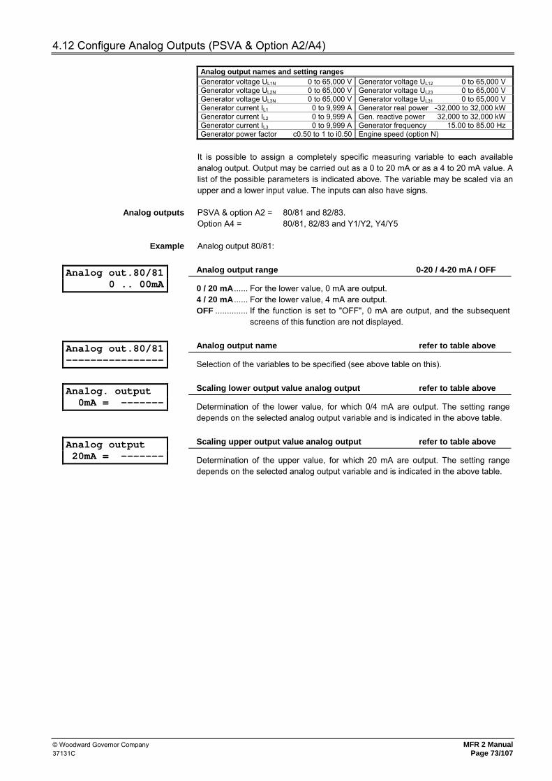
© Woodward Governor Company MFR 2 Manual 37131C Page 73/107
4.12 Configure Analog Outputs (PSVA & Option A2/A4)
Analog output names and setting ranges Generator voltage UL1N 0 to 65,000 V Generator voltage UL12 0 to 65,000 V Generator voltage UL2N 0 to 65,000 V Generator voltage UL23 0 to 65,000 V Generator voltage UL3N 0 to 65,000 V Generator voltage UL31 0 to 65,000 V Generator current IL1 0 to 9,999 A Generator real power -32,000 to 32,000 kW Generator current IL2 0 to 9,999 A Gen. reactive power 32,000 to 32,000 kW Generator current IL3 0 to 9,999 A Generator frequency 15.00 to 85.00 Hz Generator power factor c0.50 to 1 to i0.50 Engine speed (option N)
It is possible to assign a completely specific measuring variable to each available analog output. Output may be carried out as a 0 to 20 mA or as a 4 to 20 mA value. A list of the possible parameters is indicated above. The variable may be scaled via an upper and a lower input value. The inputs can also have signs.
Analog outputs PSVA & option A2 = 80/81 and 82/83. Option A4 = 80/81, 82/83 and Y1/Y2, Y4/Y5
Example Analog output 80/81:
Analog out.80/81 0 .. 00mA
Analog output range 0-20 / 4-20 mA / OFF
0 / 20 mA ...... For the lower value, 0 mA are output. 4 / 20 mA ...... For the lower value, 4 mA are output. OFF .............. If the function is set to "OFF", 0 mA are output, and the subsequent
screens of this function are not displayed.
Analog out.80/81 ----------------
Analog output name refer to table above
Selection of the variables to be specified (see above table on this).
Analog. output 0mA = -------
Scaling lower output value analog output refer to table above
Determination of the lower value, for which 0/4 mA are output. The setting range depends on the selected analog output variable and is indicated in the above table.
Analog output 20mA = -------
Scaling upper output value analog output refer to table above
Determination of the upper value, for which 20 mA are output. The setting range depends on the selected analog output variable and is indicated in the above table.

MFR 2 Manual © Woodward Governor Company Page 74/107 37131C
4.13 Interface
4.13.1 Modbus RTU Slave (Option Su/Sb)
Control by MODBUS ON
Control with MOD bus RTU slave ON/OFF
ON ............The control via the serial interface is activated and accepts control commands, that come via the interface.
OFF ..........The reception of control data is rejected.
Interface fault Relay outp. 0000
Signal interface fault on relay 0-4
The triggering of the watchdog is output to the signal relay set here. If there is to be no signaling via relay, "0000" is to be set in this position. This screen can only be seen if the screen "Change relay assignment" is set to YES.
Delay to send MOD-Bus 00,0ms
Waiting time transmission 0,2-50,0 ms
Using an interface RS485 the bus is released at a certain point of time for only one user for transmitting. As the MOD bus is a master slave system, the release of the bus is determined by a master. Only if the master, for example a PLC, has released the bus, the MFR 2 (= slave) can send. Depending on which master is used, the MFR 2 must wait for this release command different times after receipt of the master message. A shorter waiting period accompanies a high data transmission rate. How-ever if the waiting period is selected smaller than the release time of the master transmission faults occur. In this screen the waiting time of the MFR 2 can be ad-justed according to the respective master.
4.13.2 Siemens DK3964 (Option Su/Sb)
Interface ON
Interface ON/OFF
ON ............The interface is activated. OFF ..........The interface is deactivated.
Baud rate 0000
Baud rate 1,200 / 2,400 / 4,800 / 9,600 / 19,200 baud
The data transmission rate is set here. It must be conform with the other bus partici-pants.
Parity none
Parity none / direct / indirect
The data transmission rate is set here. It must be conform with the other bus partici-pants.
Sending cycle 00s
Transmission cycle time 0-10 s
The transmission cycle time is the time distance between two transmissions.
Interpreter Rk512 ON
Interpreter Siemens DK3964 RK512 ON/OFF
ON ............The interpreter RK512 is activated. OFF ..........The interpreter RK512 is de-activated.

© Woodward Governor Company MFR 2 Manual 37131C Page 75/107
Data module 000
Data component 0-255
Data component address in the receiver (e.g. SPS).
Data word 000
Data word 0-255
Data word address in the receiver (e.g. SPS).
Interface fault Relay outp. 0000
Signal interface fault on relay 0-4
The triggering of the watchdog is output to the signal relay set here. If there is to be no signaling via relay, "0000" is to be set in this position. This screen can only be seen if the screen "Change relay assignment" is set to YES.
4.13.3 Profibus DP (Option Su/Sb)
PROFIBUS-Station 000
Station number Profibus DP Slave 1-125
The station number must be entered here under which the MFR 2 transmits and re-ceives via the Profibus.
Control by< PROFIBUS OFF
[only with option Sb]
Setpoint value and acknowledgment via Profibus ON/OFF
ON ............The data received via the Profibus are accepted from the MFR 2 (see re-ceiving telegram). It can be acknowledged via the Profibus and setpoints are accepted by the MFR 2 via Profibus (if the discrete input "Changing setpoint 1<->2" is set).
OFF ..........The received data were ignored by the MFR 2.
PROFIBUS Watchdog OFF
[only with option Sb]
Toggle-Watchdog ON/OFF
The possibility to enable a watchdog in and for the interface telegram using byte 1, bit 0 Es is given. This bit is to be toggled minimum every 4 seconds from the trans-mitting device. The toggle bit - and through this the function - of transmission of the Profibus can be monitored from the MFR 2. ON ............The toggle bit is monitored from the MFR 2. If there is no change in the
toggle bit at least every 4 seconds an interface alarm is triggered, and the Profibus interface is re-initialized.
OFF ..........The toggle bit status is ignored. Important note: Independent of the toggle bit two watchdog bits are available in control word 3 (refer to the interface protocol). This have to be transmitted with status '0' and re-set a counter in the MFR 2. If status '0' is not received for at least every 15 seconds an in-terface alarm in the MFR 2 is triggered. This watchdog can not be deactivated and has to be triggered always!

MFR 2 Manual © Woodward Governor Company Page 76/107 37131C
Interface fault Relay outp. 0000
[only with option Sb]
Signal interface fault on relay 0-4
The triggering of the watchdog is output to the signal relay set here. If there is to be no signaling via relay, "0000" is to be set in this position. This screen can only be seen if the screen "Change relay assignment" is set to YES.
NOTE
Please use the attached file Leon00d9.gsd to configure your PLC.
If the Toggle watchdog is not used then the first 8 byte have to be transmitted with the content „0“ to the MFR 2. The user data consisting of three control words, always start after byte 8 (see receiving telegram).
4.13.4 CAN Bus Interface
Control by Interface ON
Control via interface ON/OFF
ON ............The control via the serial interface is activated and accepts control com-mands, that come via the interface. The control of the interface is active and releases interface faults, if longer than 30 seconds no message will be received. In case of an interface fault only the relay configured for centralized alarm will be switched.
OFF ..........The reception of control data is rejected, and the control of the interface is deactivated.
4.14 Counter Configuration
4.14.1 Setting of the Maintenance Call
Service interval in 0000h
Maintenance call 0-9,999 h
A maintenance interval is specified via this screen. A maintenance call (alarm class 1, "Maintenance") is displayed after this time interval. In automatic mode, the remaining time until the next maintenance call can be displayed in the display. After acknowledgement of the maintenance signal, a new maintenance interval begins.
4.14.2 Setting of the Operation Hours Counter
Set oper. hour counter: 00000h
Setting operation hours counter 0-65,000 h
The operating hours counter is set in a 2-level procedure: 1st step........Setting and saving the desired counter state 2nd step .......Integration of the new counter state by
• changing from configuration to automatic mode • visualization of the operating hours counter • simultaneously pressing the buttons "Select " and "Cursor" for at
least 10 seconds

© Woodward Governor Company MFR 2 Manual 37131C Page 77/107
4.14.3 Setting of the start counter
Set counter of starts 00000
Setting start counter 0-49,999
Exceeding the "Minimum frequency for monitoring" for the first time counts as a start. The start counter is set in a 2-step procedure: 1st step........Setting and saving the desired start number 2nd step .......Integrating the saved start number by
• changing from configuration to automatic mode • visualization of the start counter • simultaneously pressing the buttons "Select" and "Cursor" for at
least 10 seconds.
4.14.4 Setting of the Energy Counter
The counters are set using a two-level procedure. 1st step........Setting the desired counter state 2nd step.......Integrating the new counter state:
• Changing from configuration to automatic mode • Visualization of the counter to be set (in the display) • Simultaneously pressing the buttons "Select" and "Cursor" for at
least 10 s
energy counter set in xxxx
Setting energy counter kilo/Mega
kilo ...........The entry of the manipulated variables in the subsequent screens is made in the unit kWh or kvarh.
Mega ........The entry of the manipulated variables in the subsequent screens is made in the unit MWh or Mvarh.
Set pos. active energy 00000xWh
Configure positive real energy 0-65,500 kWh/MWh
This value is integrated into the counter of the electrical real energy only after carrying out the procedure described above as a new counter state.
Set neg. active energy 00000xWh
Configure negative real energy 0-65,500 kWh/MWh
This value is only integrated into the counter of the electrical real energy in the negative direction only after carrying out the procedure described above as a new counter state.
Set lagg. react. ener. 00000xvarh
Configure lagging r-eactive energy 0-65,500 kvarh/Mvarh
This value is integrated into the counter of the lagging reactive energy only after carrying out the procedure described above as a new counter state.
Set lead. react. ener. 00000xvarh
Configure leading re-active energy 0-65,500 kvarh/Mvarh
This value is integrated in the counter of leading reactive energy only after carrying out the procedure described above as a new counter state.
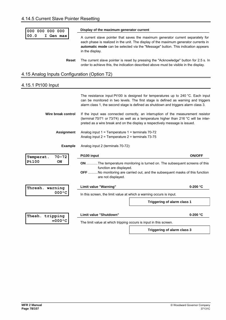
MFR 2 Manual © Woodward Governor Company Page 78/107 37131C
4.14.5 Current Slave Pointer Resetting
000 000 000 000 00.0 I Gen max
Display of the maximum generator current
A current slave pointer that saves the maximum generator current separately for each phase is realized in the unit. The display of the maximum generator currents in automatic mode can be selected via the "Message" button. This indication appears in the display.
Reset The current slave pointer is reset by pressing the "Acknowledge" button for 2.5 s. In order to achieve this, the indication described above must be visible in the display.
4.15 Analog Inputs Configuration (Option T2)
4.15.1 Pt100 Input
The resistance input Pt100 is designed for temperatures up to 240 °C. Each input can be monitored in two levels. The first stage is defined as warning and triggers alarm class 1, the second stage is defined as shutdown and triggers alarm class 3.
Wire break control If the input was connected correctly, an interruption of the measurement resistor (terminal 70/71 or 73/74) as well as a temperature higher than 216 °C will be inter-preted as a wire break and on the display a respectively message is issued.
Assignment Analog input 1 = Temperature 1 = terminals 70-72 Analog input 2 = Temperature 2 = terminals 73-75
Example Analog input 2 (terminals 70-72):
Temperat. 70-72 Pt100 ON
Pt100 input ON/OFF
ON ............The temperature monitoring is turned on. The subsequent screens of this function are displayed.
OFF ..........No monitoring are carried out, and the subsequent masks of this function are not displayed.
Thresh. warning 000°C
Limit value "Warning" 0-200 °C
In this screen, the limit value at which a warning occurs is input.
Triggering of alarm class 1
Thesh. tripping =000°C
Limit value "Shutdown" 0-200 °C
The limit value at which tripping occurs is input in this screen.
Triggering of alarm class 3

© Woodward Governor Company MFR 2 Manual 37131C Page 79/107
Hyst. warning =000°C
Hysteresis "Warning" 0-200 °C
In order for the warning to be resettable, the limit value warning minus hysteresis must be fallen below.
Hyst. tripping =000°C
Hysteresis "Shutdown" 0-200 °C
In order that the tripping is resettable, the limit value tripping minus the hysteresis must be fallen below.
Thresh. warning Delay =000s
Delay "Warning" 0-999 s
In order for a warning to be possible, the limit value must be uninterruptedly exceeded for at least as long as indicated in this screen.
Thresh.tripping Delay =000 s
Delay "Shutdown" 0-999 s
In order for a tripping to be possible, the limit value must be uninterruptedly exceeded at least as long as specified in this screen.
Warning Relay outp. 0000
"Warning" on relay 0-4
The exceeding of the limit value warning will be issued on the here adjusted signal relays. If there is to be no signaling via relay, "0000" is to be set in this position. This screen can only be seen if the screen "Change relay assignment" is set to YES.
Tripping Relay outp. 0000
"Shutdown" on relay 0-4
The exceeding of the value tripping will be issued on the here adjusted signal relays. If there is to be no signaling via relay, "0000" is to be set in this position. This screen can only be seen if the screen "Change relay assignment" is set to YES.
4.15.2 Scaleable Analog Input 0/4-20 mA
The signal 0/4-20 mA is a linear converted numerical value. The measuring value, which results of this conversion, will be displayed in the automatic mode as long as the value is within the defined signal limits. Two control limits can be defined. If the input signal is defined on 4-20 mA, additionally wire break control can be activated.
Example Analog input 1 (terminal 70-72)
Analog input 1 term.70/71 OFF
Analog input 1 ON/OFF
ON ............The display of the measuring value in automatic mode is activated and the following adjustable limit values will be monitored. The subsequent screens of this function are displayed.
OFF ..........The display of the measuring value in automatic mode will be set zero and the input is not monitored. The subsequent screens of this function are displayed.
Analog input 1 Type 0/4-20mA
Signal range 0-20 / 4-20 mA
0-20 mA....The minimum value of the input signal is 0 mA and the maximum value is 20 mA. No wire break monitoring occurs.
4-20 mA....The minimum value of the input signal is 4 mA and the maximum value is 20 mA. If the signal falls below 2 mA value the message "wire break" oc-curs and the relay centralized alarm responds.

MFR 2 Manual © Woodward Governor Company Page 80/107 37131C
Value at 0/4mA = ±0000
Numerical value at 0mA or 4mA -9,999-0-+9,999
The mA-signal is converted into a numerical values and is displayed. For converting the numerical value which corresponds to the lower signal limit is entered here.
Value at 20mA = ±0000
Numerical value at 20mA -9,999-0-+9,999
The mA-signal is converted into a numerical value and is displayed. For converting the numerical value which corresponds to the upper signal limit is entered here.
Anin 1 monitor. for xxxxxxxxx
Monitoring for ... high limit mon. / low limit mon.
high limit mon. The monitoring of the measuring value occurs on exceeding. That means that the MFR 2 responds it the measured value is larger than the set limit value.
low limit mon. The monitoring of the measuring value occurs on negative deviation. That means that the MFR 2 responds it the measured value is smaller than the set limit value..
Thresh. warning Value =±0000
Limit value "Warning" -9,999-0-+9,999
The limit value at which in case of exceeding or negative deviation warning occurs is configured here.
Thresh. tripping Value =±0000
Limit value "Shutdown" -9,999-0-+9,999
The limit value at which in case of exceeding or negative deviation tripping occurs is configured here.
Thresh. warning Delay =000s
Delay for "Warning" 0-999 s
In order for warning to occur, the limit value must be exceeded or fallen below with-out interruption for at least the period of time specified in this screen.
Thresh. tripping Delay =000s
Delay for "Shutdown" 0-999 s
In order for tripping to occur, the limit value must be exceeded or fallen below without interruption for at least the period of time specified in this screen.
Thresh. warning Relay outp. 0000
"Warning" on relay 0-4
The exceeding of the value warning will be issued on the here adjusted signal relays. If there is to be no signaling via relay, "0000" is to be set in this position. This screen can only be seen if the screen "Change relay assignment" is set to YES.
Thresh. tripping Relay outp. 0000
"Shutdown" on relay 0-4
The exceeding of the value tripping will be issued on the here adjusted signal relays. If there is to be no signaling via relay, "0000" is to be set in this position. This screen can only be seen if the screen "Change relay assignment" is set to YES.

© Woodward Governor Company MFR 2 Manual 37131C Page 81/107
4.15.3 Input PTC 0-16.5 kΩ for Generator Temperature
The measured resistance 0-16.5 kΩ will be linear converted into 0-100 %. A monitoring limit can be defined.
Generatortemp. PTC OFF
Analog input PTC ON/OFF
ON ............The following adjustable limit value is monitored, and the following screens of this function are displayed.
OFF ..........The input is not monitored, and the following screens of this function are not displayed.
Threshold Gen.Temp.= 000%
Limit value generator temperature 0-100 %
The limit value at which in case of exceeding tripping occurs is configured here.
Operate delay Gen.Temp. =000s
Delay 0-600 s
In order that tripping occurs, the limit value must be exceeded for at least the period of time specified in this screen.
Revert delay Gen.Temp. =000s
Hysteresis delay 0-600 s
In order that the tripping is reset, the limit value must fall below for at least the period of time specified in this screen.
Hysteresis Gen.Temp. = 00%
Hysteresis 0-50 %
In order that the tripping can be reset, the limit value minus the hysteresis must be fall below.
Generatortemp. Relay outp. 0000
Alarm on relay 0-4
The exceeding of the value will be issued on the here adjusted signal relays. If no signal shall occur via relay, "0000" is to be set in this position. This screen can only be seen if the screen "Change relay assignment" is set to YES.
4.15.4 Input 0-150 mV for Battery Current Monitoring
Batt. current monitoring OFF
Battery current ON/OFF
ON ............The following adjustable limit values are monitored, and the following screens of this function are displayed.
OFF ..........The input is not monitored, and the following screens of this function are not displayed.
Batt. current 0mV = 00,0 A
Battery current at 0 mV 0.0-99.9 A
The mV signal of the analog input will be converted into a battery current in A and monitored. For converting the value in A - which corresponds to the lower signal limit of 0 mV - must be set here.
Batt. current 150mV = 00,0 A
Battery current at 150 mV 0.0-99.9 A
The mV signal of the analog input will be converted into a battery current in A and monitored. For converting the value in A - which corresponds to the upper signal limit of 150 mV - must be set here.

MFR 2 Manual © Woodward Governor Company Page 82/107 37131C
Thresh. level 1 Curr. = 00,0 A
Limit value battery current level 1 0.0-99.9 A
The limit value of level 1 which should be monitored, is set here.
Thresh. level 2 Curr. = 00,0 A
Limit value battery current level 2 0.0-99.9 A
The limit value of level 1 which should be monitored, is set here.
Batt. overcur 1 Delay =000s
Delay tripping level 1 0-600 s
To occur a tripping of level 1, the limit value of level 1 must be exceeded at least for the time monitored in this screen.
Batt.overcur 2 Delay =000s
Delay tripping level 2 0-600 s
To occur a tripping of level 2, the limit value of level 2 must be exceeded at least for the time monitored in this screen.
Batt. overcur 1 Relay outp. 0000
Tripping level 1 on relay 0-4
The exceeding of the limit value of level 1 will be issued on the here adjusted signal relays. If no signal shall occur via relay, "0000" is to be set in this position. This screen can only be seen if the screen "Change relay assignment" is set to YES.
Batt.overcur 2 Relay outp. 0000
Tripping level 2 on relay 0-4
The exceeding of the limit value of level 2 will be issued on the here adjusted signal relays. If no signal shall occur via relay, "0000" is to be set in this position. This screen can only be seen if the screen "Change relay assignment" is set to YES.

© Woodward Governor Company MFR 2 Manual 37131C Page 83/107
4.16 Discrete Inputs Configuration
Discrete inputs Discrete input 1 terminal 34 not used Discrete input 2 terminal 35 Control input "Isolated controller ON" Discrete input 3 terminal 36 Control input "External acknowledgement" Discrete input 4 terminal 60 Control input "Blocking mains protection" Discrete input 5 terminal 61 Alarm input Discrete input 6 terminal 62 Alarm input Discrete input 7 terminal 63 Alarm input Discrete input 8 terminal 64 Alarm input
a.) Mode of operation
Operating current (NO) In order to activate the function of the discrete input in question, or in order to trigger a alarm, this must be set; i.e. the associated terminal is connected to voltage.
Idle current (NC) If the terminal is not wired or not set, thus de-energized, the associated function of the discrete input is active. In this way, the inputs can be wired in a fail-safe manner.
Dig. input 234 Function: 000
Function of discrete inputs 2, 3 and 4 E/R
A choice is made between different control principles by selecting either operating current contact or idle current contact (see above). E ...............Energize to operate: The dig. input functions as a working current input. R ...............Release to operate: The discrete input functions as a idle current input.
Dig. input 5678 Function: 0000
Function of discrete inputs 5, 6, 7 and 8 E/R
A choice is made between different control principles by selecting either operating current contact or idle current contact (see above). E ...............Energize to operate: The dig. input functions as a working current input. R ...............Release to operate: The discrete input functions as a idle current input.
Dig. input 5678 delayed 0000
Delay of discrete inputs 5, 6, 7 and 8 Y/N
Y ...............The associated alarm input is registered only if the minimum frequency for monitoring is exceeded.
N ...............The discrete output is always evaluated.
Dig. input 5678 Err. class 0000
Alarm class of discrete inputs 5, 6, 7 and 8 0-3
Different alarm classes are assigned to discrete alarm inputs 5 to 8.

MFR 2 Manual © Woodward Governor Company Page 84/107 37131C
b.) Alarm texts
The alarm texts are displayed in the case of activation of an associated alarm input.
Fault text: t.61 Terminal 61
Alarm text terminal 61 optional
Using the buttons "Cursor→", "Digit↑" and "Select" the alarm texts can be set. Letters and digits, as well as a few special characters, can be inserted.
Fault text:t. 62 Terminal 62
Alarm text terminal 62 optional
Using the buttons "Cursor→", "Digit↑" and "Select" the alarm texts can be set. Letters and digits, as well as a few special characters, can be inserted.
Fault text:t. 63 Terminal 63
Alarm text terminal 63 optional
Using the buttons "Cursor→", "Digit↑" and "Select" the alarm texts can be set. Letters and digits, as well as a few special characters, can be inserted.
Fault text:t.64 Terminal 64
Alarm text terminal 64 optional
Using the buttons "Cursor→", "Digit↑" and "Select" the alarm texts can be set. Letters and digits, as well as a few special characters, can be inserted.
4.17 Configure Password
NOTE
Once the code level is set, this is not changed, even if the configuration mode is accessed steady. If an incorrect code number is input, the code level is set to CL0, and the item is thereby blocked for third parties.
If the supply voltage is present, uninterrupted, at the item for 2 hours, code level 0 is automatically set.
Define level 1 code XXXX
Code level 1 (customer) 0000-9999
This screen first appears in code level 2 (password protection enabled). Following the input of digits in this screen, the code level for level 1 (Customer) is set. More in-formation to password protection see on page 39.
Define level 2 code XXXX
Code level 2 (commissioner) 0000-9999
This screen first appears in code level 2 (password protection enabled). Following the input of digits in this screen, the code level for level 2 (mechanic) is set. More in-formation to password protection see on page 39.

© Woodward Governor Company MFR 2 Manual 37131C Page 85/107
5 Commissioning
DANGER !!!
When commissioning the unit, please observe the five safety rules that apply to the handling of live equipment. Make sure that you know how to provide first aid in current-related accidents and that you know where the first-aid kit and the nearest telephone are. Never touch any live components of the system or on the back of the system:
DANGER TO LIFE
WARNING !
The unit may only be commissioned by a qualified technician. The "EMERGENCY STOP" function must be safely working prior to the commissioning, and must not depend on the unit.
ATTENTION
1. Prior to the commissioning make sure that all measuring voltages are connected in correct phase sequence. The rotating field must be measured. Any lack or incorrect connection of measuring voltages or other signals may lead to incorrect functions and damage the unit as well as engines and components connected to the unit.
Procedure 2. The power supply (24 VDC) must be applied following a check to ensure that all measuring voltages have been connected in the correct phase relation.
3. Change into the output mode and setting of all operating data. 4. In absence of all releases and replies, there must be a check as to whether the applied
voltages correspond to the displayed values. Attention: If there is no measuring voltage, this may lead to an asynchronous/induction add-on order in case of an active dead bus operation!
5. Check the entire wiring to the MFR 2. The wiring of some relays can be checked by chang-
ing from closed circuit current (NO) to operating current (NC) and thus to switch (please do not forget after the check to configure them again correctly). The response of the circuit breakers must be checked.
6. Execute now the test of the protective functions for the generator 7. Synchronize the GCB or the MCB. Before inserting one of the two circuit breaker it is abso-
lutely necessary to check whether the measuring voltages are attached correctly. It must also be checked whether the synchronous conditions are fulfilled in the moment when the MFR 2 issues an add-on pulse. This check can easily occur in measuring the difference voltage directly at the appropriate circuit breaker.
8. After a successful check of the synchronization please check the monitored current values,
the power direction and the monitored power factor. 9. Please carry out further possible checks (depending on the application and the equipment
of the MFR 2).

MFR 2 Manual © Woodward Governor Company Page 86/107 37131C
6 Appendix
6.1 Interface (Standard, Terminals X1-X5)
6.1.1 Transmission Telegram
The data of the following table can be handled by a PLC, a Gateway GW 4 or any other suitable receiving unit. The CAN-ID on which the MFR 2 transmits is generated by the number 800 (= 320hex) plus the set generator number: CAN-ID = 800 + generator number Each separate message is assembled out of 8 Byte and is built as follows:
Byte 0 Byte 1 Byte 2 Byte 3 Byte 4 Byte 5 Byte 6 Byte 7
MUX-number H‘DD Data word 1 High-Byte
Data word 1 Low-Byte
Data word 2 High-Byte
Data word 2 Low-Byte
Data word 3 High-Byte
Data word 3 Low-Byte
Byte 1 is always used to show the hexadecimal value DD. This one defines the mes-sage as a visualization message. Byte 0 sends a MUX number which enumerates from 1 to 13. The following table shows which data word assigns to the respective MUX number. The transmitting counter in word 38 can be used to monitor the functional efficiency of the CAN at the MFR 2. This counter is increased by one after sending a message. It must be increased thus always by 13 if it sends itself, because the whole telegram consists of 13 messages.

© Woodward Governor Company MFR 2 Manual 37131C Page 87/107
CAN-Bus No. Content (words) Unit Comment
MUX=1,1 1 Telegram call sign "408" Telegram type MUX=1,2 2 Generator voltage L12 V × 10UGNEXPO MUX=1,3 3 Generator voltage L23 V × 10UGNEXPO MUX=2,1 4 Generator voltage L31 V × 10UGNEXPO MUX=2,2 5 Generator frequency Hz × 100 MUX=2,3 6 Generator current L1 A × 10IGNEXPO MUX=3,1 7 Generator current L2 A × 10IGNEXPO MUX=3,2 8 Generator current L3 A × 10IGNEXPO MUX=3,3 9 Generator power factor dim.los × 100 -99-100-+99 MUX=4,1 10 Generator real power W × 10PGNEXPO MUX=4,2 11 Busbar voltage V × 10UGNEXPO 100 V units: V × 10USSEXPO MUX=4,3 12 Busbar frequency Hz × 100 MUX=5,1 13 Mains voltage L12 V × 10UNTEXPO MUX=5,2 14 Mains voltage L23 V × 10UNTEXPO MUX=5,3 15 Mains voltage L31 V × 10UNTEXPO MUX=6,1 16 Mains frequency Hz × 100 MUX=6,2 17 Mains current L1 A × 10INTEXPO MUX=6,3 18 Mains power factor dim.los × 100 -99-100-+99 MUX=7,1 19 Mains interchange real power W × 10PNTEXPO MUX=7,2 20 Status of the power circuit breakers Bit 15 = 1 \
Bit 14 = 1 / Internal
Bit 13 = 1 \ Bit 12 = 1 / Internal
Bit 11 = 1 \ Bit 10 = 1 / Internal
Bit 9 = 1 \ Bit 8 = 1 / Internal
Bit 7 = 1 \ Bit 6 = 1 / GCB is closed
Bit 5 = 1 \ Bit 4 = 1 / MCB is closed
Bit 3 = 1 \ Bit 2 = 1 / Internal
Note: 1/1 means: watchdog has released 0/0 means: watchdog has not released
Bit 1 = 1 \ Bit 0 = 1 / Internal
MUX=7,3 21 Alarm class Bit 15 = 1 \ Bit 14 = 1 / Internal
Bit 13 = 1 \ Bit 12 = 1 / Internal
Bit 11 = 1 \ Bit 10 = 1 / Internal
Bit 9 = 1 \ Bit 8 = 1 / Internal
Bit 7 = 1 \ Bit 6 = 1 / Alarm class 3
Bit 5 = 1 \ Bit 4 = 1 / Alarm class 2
Bit 3 = 1 \ Bit 2 = 1 / Alarm class 1
Note: 1/1 means: watchdog has released 0/0 means: watchdog has not released
Bit 1 = 1 \ Bit 0 = 1 / Internal

MFR 2 Manual © Woodward Governor Company Page 88/107 37131C
CAN-Bus Nr. Content (words) Unit Comment
MUX=8,1 22 Internal alarms 1 Bit 15 = 1 \
Bit 14 = 1 / Generator overfrequency
Bit 13 = 1 \ Bit 12 = 1 / Generator underfrequency
Bit 11 = 1 \ Bit 10 = 1 / Generator overvoltage
Bit 9 = 1 \ Bit 8 = 1 / Generator undervoltage
Bit 7 = 1 \ Bit 6 = 1 /
Limiting performance reached
Bit 5 = 1 \ Bit 4 = 1 / Battery undervoltage
Bit 3 = 1 \ Bit 2 = 1 / Generator overload
Note: 1/1 means: watchdog has released 0/0 means: watchdog has not released
Bit 1 = 1 \ Bit 0 = 1 / Generator reverse power
MUX=8,2 23 Internal alarme 2 Bit 15 = 1 \ Bit 14 = 1 / Mains overfrequency
Bit 13 = 1 \ Bit 12 = 1 / Mains underfrequency
Bit 11 = 1 \ Bit 10 = 1 / Mains overvoltage
Bit 9 = 1 \ Bit 8 = 1 / Mains undervoltage
Bit 7 = 1 \ Bit 6 = 1 / df/dt
Bit 5 = 1 \ Bit 4 = 1 /
Synchronization time exceeded
Bit 3 = 1 \ Bit 2 = 1 / Mains asymmetry
Note: 1/1 means: watchdog has released 0/0 means: watchdog has not released
Bit 1 = 1 \ Bit 0 = 1 / Mains vector jump
MUX=8,3 24 Internal alarms 3 Bit 15 = 1 \ Bit 14 = 1 /
Re-active power lagging
Bit 13 = 1 \ Bit 12 = 1 /
Re-active power leading
Bit 11 = 1 \ Bit 10 = 1 / Interface alarm
Bit 9 = 1 \ Bit 8 = 1 / Unbalanced load
Bit 7 = 1 \ Bit 6 = 1 /
Generator overcurrent, level 1
Bit 5 = 1 \ Bit 4 = 1 / Generator overtemperature
Bit 3 = 1 \ Bit 2 = 1 / Maintenance call
Note: 1/1 means: watchdog has released 0/0 means: watchdog has not released
Bit 1 = 1 \ Bit 0 = 1 / False start
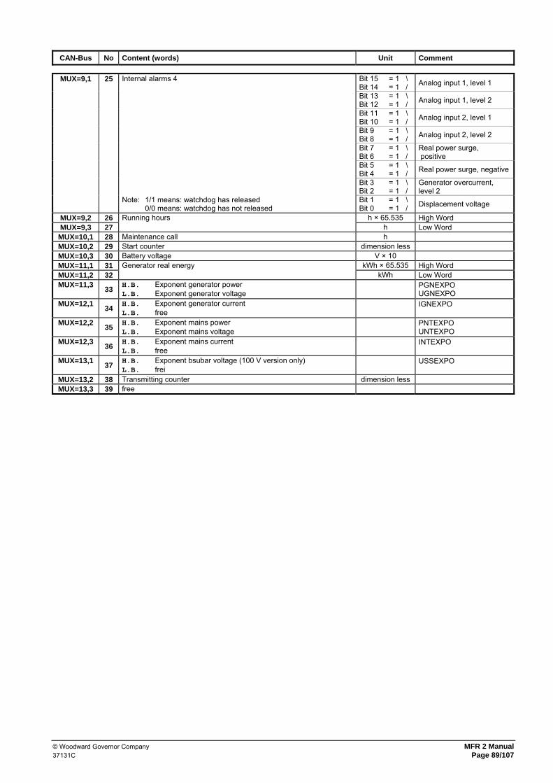
© Woodward Governor Company MFR 2 Manual 37131C Page 89/107
CAN-Bus No Content (words) Unit Comment
MUX=9,1 25 Internal alarms 4 Bit 15 = 1 \
Bit 14 = 1 / Analog input 1, level 1
Bit 13 = 1 \ Bit 12 = 1 / Analog input 1, level 2
Bit 11 = 1 \ Bit 10 = 1 / Analog input 2, level 1
Bit 9 = 1 \ Bit 8 = 1 / Analog input 2, level 2
Bit 7 = 1 \ Bit 6 = 1 /
Real power surge, positive
Bit 5 = 1 \ Bit 4 = 1 / Real power surge, negative
Bit 3 = 1 \ Bit 2 = 1 /
Generator overcurrent, level 2
Note: 1/1 means: watchdog has released 0/0 means: watchdog has not released
Bit 1 = 1 \ Bit 0 = 1 / Displacement voltage
MUX=9,2 26 Running hours h × 65.535 High Word MUX=9,3 27 h Low Word
MUX=10,1 28 Maintenance call h MUX=10,2 29 Start counter dimension less MUX=10,3 30 Battery voltage V × 10 MUX=11,1 31 Generator real energy kWh × 65.535 High Word MUX=11,2 32 kWh Low Word MUX=11,3 33 H.B. Exponent generator power
L.B. Exponent generator voltage PGNEXPO UGNEXPO
MUX=12,1 34 H.B. Exponent generator current L.B. free IGNEXPO
MUX=12,2 35 H.B. Exponent mains power
L.B. Exponent mains voltage PNTEXPO UNTEXPO
MUX=12,3 36 H.B. Exponent mains current L.B. free INTEXPO
MUX=13,1 37 H.B. Exponent bsubar voltage (100 V version only)
L.B. frei USSEXPO
MUX=13,2 38 Transmitting counter dimension less MUX=13,3 39 free

MFR 2 Manual © Woodward Governor Company Page 90/107 37131C
6.1.2 Receiving Telegram
The data of the following table can be handled by a PLC or with any other suitable re-ceiving unit. The CAN ID on which the MFR 2 receives is 831 (= 33Fhex). Each separate message is assembled out of 8 Byte and is built as follows:
Byte 0 Byte 1 Byte 2 Byte 3 Byte 4 Byte 5 Byte 6 Byte 7
H‘EE Generator number
Address High-Byte
Address Low-Byte
Data word High-Byte
Data word Low-Byte
Check sum High-Byte
Check sum Low-Byte
The byte 0 is always used to show the hexadecimal value EE. This one defines the message as a visualization message. On Byte 1 the generator number of the ad-dressed MFR 2 must be send. For the address of Byte 2 and 3 is valid: Set value Real power = 501 (= 1F5hex), set value power factor = 502 (= 1F6hex), control word = 503 (= 1F7hex). The test amounts were calculated as follows: - Highbyte = (Byte 0) XOR (Byte 2) XOR (Byte 4), - Lowbyte = (Byte 1) XOR (Byte 3) XOR (Byte 5). The following data words can be received by the MFR 2.
No Content (words) Unit Comment
1 Set value for real power kW see below 2 Set value for generator cos ϕ
Example: 0064H cos ϕ = 1.00 0063H cos ϕ = i 0.99 (lagging) FF9EH cos ϕ = k0.98 (leading)
3 Control word Bit 15 Internal Bit 14 Internal Bit 13 Internal Bit 12 Internal Bit 11 Internal Bit 10 Internal Bit 9 Internal Bit 8 Internal Bit 7 Internal Bit 6 Internal Bit 5 Internal Bit 4 = 1 Acknowledgement Bit 3 = 0 always 0 Bit 2 = 0 always 0 Bit 1 = 1 Internal Bit 0 = 1 Internal

© Woodward Governor Company MFR 2 Manual 37131C Page 91/107
Coding of the power setpoint: The power value uses the bits 0 to 13. Bit 14 must be 1, bit 15 must be 0. Thus power rating up to 16.383 kW can be transmitted. Example: A power of 150 W shall be adjusted. Then the value to be send is: 01/00 0000 1001 0110 B 4096 H
NOTE
To process the setpoint values of the MFR 2 sent via interface, the discrete input "Setpoint value 1-2“ at terminal 5 must be set!
NOTE
If the configuration via the lateral plug is connected, the CAN interface is out of operation.
If remote control via CAN interface is switched on, the monitoring of the interface is also active. An interface fault is tripped if bit 2 in the control word is more than 30 seconds set to "1" or if bit 3 in the control word has not send with "0" for more than 30 seconds or the whole control word was not send for more than 30 seconds. So that this monitoring can also include the setpoint messages, it is absolutely nec-essary that always all three words were sent consecutively. If an interface fault is tripped, the configured fixed setpoint values were consulted for control.
6.2 Interface (Option Su/Sb; Terminals Y1-Y5)
6.2.1 Transmission Telegram
NOTE
Units of version 3.4000 and 3.4002 are sending the telegram type 408. This is identically to type 409 except the information of the displacement voltage.
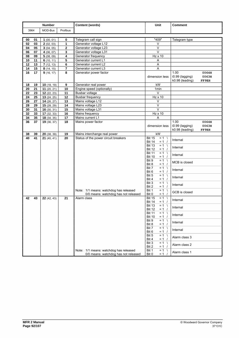
MFR 2 Manual © Woodward Governor Company Page 92/107 37131C
Number Content (words) Unit Comment
3964 MOD-Bus Profibus
00 01 1 (00, 01) 0 Telegram call sign "409" Telegram type 02 03 2 (02, 03) 1 Generator voltage L12 V 04 05 3 (04, 05) 2 Generator voltage L23 V 06 07 4 (06, 07) 3 Generator voltage L31 V 08 09 5 (08, 09) 4 Generator frequency Hz x 10 10 11 6 (10, 11) 5 Generator current L1 A 12 13 7 (12, 13) 6 Generator current L2 A 14 15 8 (14, 15) 7 Generator current L3 A 16 17 9 (16, 17) 8 Generator power factor
dimension less 1.00 0064H i0.99 (lagging) 0063H k0.98 (leading) FF9EH
18 19 10 (18, 19) 9 Generator real power kW 20 21 11 (20, 21) 10 Engine speed (optionally) 1min 22 23 12 (22, 23) 11 Busbar voltage V 24 25 13 (24, 25) 12 Busbar frequency Hz x 10 26 27 14 (26, 27) 13 Mains voltage L12 V 28 29 15 (28, 29) 14 Mains voltage L23 V 30 31 16 (30, 31) 15 Mains voltage L31 V 32 33 17 (32, 33) 16 Mains frequency Hz x 10 34 35 18 (34, 35) 17 Mains current L1 A 36 37 19 (36, 37) 18 Mains power factor
dimension less 1.00 0064H i0.99 (lagging) 0063H k0.98 (leading) FF9EH
38 39 20 (38, 39) 19 Mains interchange real power kW 40 41 21 (40, 41) 20 Status of the power circuit breakers Bit 15 = 1 \
Bit 14 = 1 / Internal
Bit 13 = 1 \ Bit 12 = 1 / Internal
Bit 11 = 1 \ Bit 10 = 1 / Internal
Bit 9 = 1 \ Bit 8 = 1 / MCB is closed
Bit 7 = 1 \ Bit 6 = 1 / Internal
Bit 5 = 1 \ Bit 4 = 1 / Internal
Bit 3 = 1 \ Bit 2 = 1 / Internal
Note: 1/1 means: watchdog has released 0/0 means: watchdog has not released
Bit 1 = 1 \ Bit 0 = 1 / GCB is closed
42 43 22 (42, 43) 21 Alarm class Bit 15 = 1 \ Bit 14 = 1 / Internal
Bit 13 = 1 \ Bit 12 = 1 / Internal
Bit 11 = 1 \ Bit 10 = 1 / Internal
Bit 9 = 1 \ Bit 8 = 1 / Internal
Bit 7 = 1 \ Bit 6 = 1 / Internal
Bit 5 = 1 \ Bit 4 = 1 / Alarm class 3
Bit 3 = 1 \ Bit 2 = 1 / Alarm class 2
Note: 1/1 means: watchdog has released 0/0 means: watchdog has not released
Bit 1 = 1 \ Bit 0 = 1 / Alarm class 1

© Woodward Governor Company MFR 2 Manual 37131C Page 93/107
Number Content (words) Unit Comment
3964 MOD-Bus Profibus
44 45 23 (44, 45) 22 Internal alarms Bit 15 = 1 \ Bit 14 = 1 / Generator overfrequency
Bit 13 = 1 \ Bit 12 = 1 / Generator underfrequency
Bit 11 = 1 \ Bit 10 = 1 / Generator overvoltage
Bit 9 = 1 \ Bit 8 = 1 / Generator undervoltage
Bit 7 = 1 \ Bit 6 = 1 / Generator overload
Bit 5 = 1 \ Bit 4 = 1 / Generator reverse power
Bit 3 = 1 \ Bit 2 = 1 / Battery undervoltage
Note: 1/1 means: watchdog has released 0/0 means: watchdog has not released
Bit 1 = 1 \ Bit 0 = 1 / Generator unbalanced load
46 47 24 (46, 47) 23 Internal alarms Bit 15 = 1 \ Bit 14 = 1 / Generator overcurrent 1
Bit 13 = 1 \ Bit 12 = 1 / Generator overcurrent 2
Bit 11 = 1 \ Bit 10 = 1 / Mains overfrequency
Bit 9 = 1 \ Bit 8 = 1 / Mains underfrequency
Bit 7 = 1 \ Bit 6 = 1 / Mains overvoltage
Bit 5 = 1 \ Bit 4 = 1 / Mains undervoltage
Bit 3 = 1 \ Bit 2 = 1 / Mains asymmetry
Note: 1/1 means: watchdog has released 0/0 means: watchdog has not released
Bit 1 = 1 \ Bit 0 = 1 / Mains phase shift
48 49 25 (48, 49) 24 Internal alarms Bit 15 = 1 \ Bit 14 = 1 /
Time monitoring Synchronization
Bit 13 = 1 \ Bit 12 = 1 / df/dt
Bit 11 = 1 \ Bit 10 = 1 / Internal
Bit 9 = 1 \ Bit 8 = 1 / Internal
Bit 7 = 1 \ Bit 6 = 1 /
Re-active power monitoring lagging
Bit 5 = 1 \ Bit 4 = 1 /
Re-active power monitoring leading
Bit 3 = 1 \ Bit 2 = 1 / Internal
Note: 1/1 means: watchdog has released 0/0 means: watchdog has not released
Bit 1 = 1 \ Bit 0 = 1 / Displacement voltage

MFR 2 Manual © Woodward Governor Company Page 94/107 37131C
Number Content (words) Unit Comment
3964 MOD-Bus Profibus
50 51 26 (50, 51) 25 Internal alarms Bit 15 = 1 \ Bit 14 = 1 /
Temperature monitoring temperature 1, warning
Bit 13 = 1 \ Bit 12 = 1 /
Temperature monitoring temperature 1, shutdown
Bit 11 = 1 \ Bit 10 = 1 /
Temperature monitoring temperature 2, warning
Bit 9 = 1 \ Bit 8 = 1 /
Temperature monitoring temperature 2, shutdown
Bit 7 = 1 \ Bit 6 = 1 / Internal
Bit 5 = 1 \ Bit 4 = 1 / Internal
Bit 3 = 1 \ Bit 2 = 1 / Interface alarm
Note: 1/1 means: watchdog has released 0/0 means: watchdog has not released
Bit 1 = 1 \ Bit 0 = 1 / Generator PTC
52 53 27 (52, 53) 26 Displacement voltage V 54 55 28 (54, 55) 27 Operation mode Bit 15 = 1 \
Bit 14 = 1 / Internal
Bit 13 = 1 \ Bit 12 = 1 / Internal
Bit 11 = 1 \ Bit 10 = 1 / Internal
Bit 9 = 1 \ Bit 8 = 1 / Internal
Bit 7 = 1 \ Bit 6 = 1 / Changeover setvalue 1/2
Bit 5 = 1 \ Bit 4 = 1 / Release GCB
Bit 3 = 1 \ Bit 2 = 1 / Internal
Note: 1/1 means: watchdog has released 0/0 means: watchdog has not released
Bit 1 = 1 \ Bit 0 = 1 / Internal
56 57 29 (56, 57) 28 Running hours h High Word × 65.535 58 59 30 (58, 59) 29 Low Word 60 61 31 (60, 61) 30 Maintenance call h 62 63 32 (62, 63) 31 Battery voltage V x 10 64 65 33 (64, 65) 32 Generator real energy kWh High Word × 65.535 66 67 34 (66, 67) 33 Low Word 68 69 35 (68, 69) 34 Temperature 1 °C 70 71 36 (70, 71) 35 Temperature 2 °C 72 73 37 (72, 73) 36 kvarh High Word × 65.535 74 75 38 (74, 75) 37
Generator re-active energy, positive (lagging) Low Word
76 77 39 (76, 77) 38 kvarh High Word × 65.535 78 79 40 (78, 79) 39
Generator re-active energy, negative (leading) Low Word
80 81 41 (79, 81) 40 Generator re-active power kvar

© Woodward Governor Company MFR 2 Manual 37131C Page 95/107
6.2.2 Receiving Telegram (Option Sb)
a.) Receiving Telegram via DK3964
Number Content (words) Unit/Bit Comment
3964
00 01 Reserve 02 03 Reserve 04 05 Real power setpoint kW see below 06 07 Power factor setpoint dimension less 1.00 0064H
i0.99 (lagging) 0063H c0.98 (leading) FF9EH
08 09 Acknowledgement 00F0H Acknowledgement 000FH No acknowledgement
10 11 Reserve 12 13 Reserve 14 15 Reserve 16 17 Reserve 18 19 Reserve
Coding of the power setpoint: The power value uses bits 0 to 13. Bit 14 must be 1, bit 15 must be 0. Thus power rating up to 16.383 kW can be transmitted. Example: A power of 150 W shall be adjusted. Then the value to be send is: 01/00 0000 1001 0110 B 4096 H
NOTE
To process the setpoint values of the MFR 2 sent via interface, the discrete input "Change setpoint 1-2“ at terminal 5 must be set!

MFR 2 Manual © Woodward Governor Company Page 96/107 37131C
b.) Receiving Telegram Via MOD Bus RTU Slave and Profibus DP Slave
Number Content (words) Unit Comment MOD-Bus Profibus
01 (00, 01) 4 (8,9) Generator real power Setpoint kW see below 02 (02, 03) 5 (10,11) Generator-power factor Setpoint dim.los -99-100-+99 03 (04, 05) 6 (12,13) Control word Bit 15 = 1 Internal
Bit 14 = 1 Internal Bit 13 = 1 Internal Bit 12 = 1 Internal Bit 11 = 1 Internal Bit 10 = 1 Internal Bit 9 = 1 Internal Bit 8 = 1 Internal Bit 7 = 1 Internal Bit 6 = 1 Internal Bit 5 = 1 Internal Bit 4 = 1 Alarm acknowledgement Bit 3 = 0 always 0 Bit 2 = 0 always 0 Bit 1 = 1 internal Bit 0 = 1 internal
In the control word two watchdog bits were set (Bit 2 and Bit 3). These must be al-ways send in status '0' and after every receipt a counter in the MFR 2 is reset. If for more than 15 seconds these bits were not received in status '0' the MFR 2 releases an interface fault. This watchdog can not be deactivated and has to be served al-ways! Coding of the power setpoint: The power value uses bits 0 to 13. Bit 14 must be 1, bit 15 must be 0. Thus power rating up to 16.383 kW can be transmitted. Example: A power of 150 W shall be adjusted. Then the value to be send is: 01/00 0000 1001 0110 B 4096 H
NOTE
To process the setpoint values of the MFR 2 sent via interface, the discrete input "Change setpoint 1-2" at terminal 5 must be set!

© Woodward Governor Company MFR 2 Manual 37131C Page 97/107
6.3 Framework Data for the Interfaces
6.3.1 Framework Data for the Procedure 3964 (TTY, RS232, RS485)
Data Length of characters...... 8 Bit Stop bit .......................... 1 bit Parity bit ........................ 1 bit with even parity Release condition.......... Corresponds to the log status. 1 (20 mA at TTY) Data format ................... 16-bit binary values Transmitting rate ........... 9,600 baud. Other baud rates on request. The records are
transferred cyclically. Procedure Interpreter RK 512 See Siemens documents for procedure 3964.
6.3.2 Framework Data for Hardware Handshaking RTS/CTS (RS232, RS422)
Data Length of characters 8 Bit Stop bit .......................... 1 bit Parity bit ........................ 1 bit with even parity Data format ................... 16-bit binary values Transmitting rate ........... 9,600 baud. Other baud rates on request. The records are
transferred cyclically.
Procedure If the transmitter is ready for the data transmission, it informs the receiver by setting its control wire RTS into the "ON"-status. The prerequisite of this is that no data are received (CTS = "OFF"). The receiver registers this status and indicates its readiness to receive by switching its RTS line to "ON". The transmitter can then begin transmitting when it detects this "ON" status on its CTS line. As soon as the receiver withdraws its RTS signal (RTS = "OFF"), the transmitter interrupts its transmission and waits until the receiver is ready to receive again. The initialization conflict (both subscribers set the RTS line simultaneously) and time-out (one subscriber waits in vain for a reply) must be taken into consideration.
6.3.3 Framework Data for the MOD Bus RTU Slave
Data Transmitting rate ........... 9.600 Baud. Length of characters...... 8 Bit Stop bit .......................... 1 Bit Parity bit ........................ none Protocol ......................... MOD-Bus RTU Slave Slave address................ Generator number Submitted commands.... 3, 4, 6, 16 Restrictions.................... maximum 10 words readable with one request
maximum 3 words writeble with one request
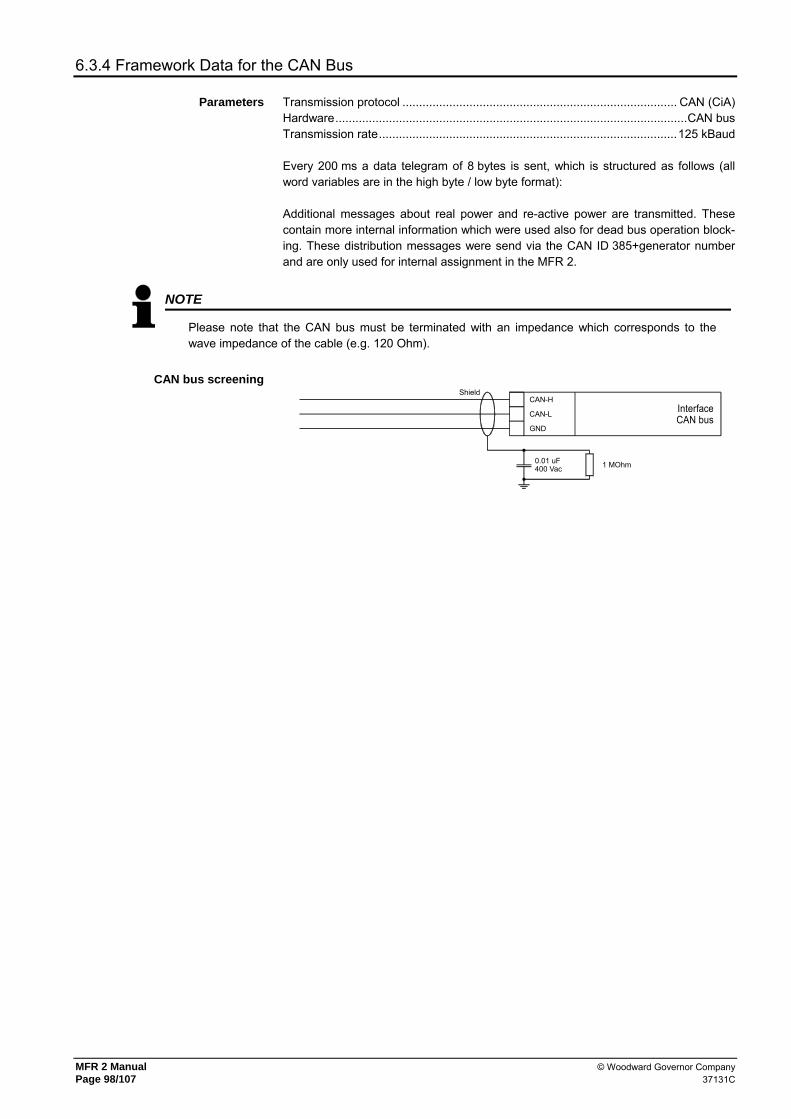
MFR 2 Manual © Woodward Governor Company Page 98/107 37131C
6.3.4 Framework Data for the CAN Bus
Parameters Transmission protocol .................................................................................. CAN (CiA) Hardware.........................................................................................................CAN bus Transmission rate.........................................................................................125 kBaud Every 200 ms a data telegram of 8 bytes is sent, which is structured as follows (all word variables are in the high byte / low byte format): Additional messages about real power and re-active power are transmitted. These contain more internal information which were used also for dead bus operation block-ing. These distribution messages were send via the CAN ID 385+generator number and are only used for internal assignment in the MFR 2.
NOTE
Please note that the CAN bus must be terminated with an impedance which corresponds to the wave impedance of the cable (e.g. 120 Ohm).
CAN bus screening
InterfaceCAN bus
CAN-H
CAN-L
GND
Shield
1 MOhm0.01 uF400 Vac

© Woodward Governor Company MFR 2 Manual 37131C Page 99/107
6.3.5 Framework Data for the Profibus DP Slave
Receiving range Byte 0 and the following .......................................... Telegram according to description For example: No. 1 - byte 0/1 = Telegram ID "302"
No. 2 - byte 2/3 = voltage L12 No. 3 - byte 4/5 = voltage L23 No. 4 - byte 6/7 = voltage L31 etc. Byte 185 ....... The bit 0 inverts every 2.5 seconds. This can be used for control if the
interface still functions flawlessly.
Received data Byte 0 ....................................................Block pre-selection (is not taken into account) Byte 1 ........... The bit 0 is used as a watchdog. If monitoring is switched on in the
configuration screen, this bit must be flipped every 4 seconds. The unit monitors this and possibly triggers a alarm and reinitializes the interface.
Byte 2-7............................................................................................. must be always 0 Byte 8/9 ...............................................................................Word No. 5 (see telegram) Byte 10/11 ...........................................................................Word No. 6 (see telegram) Byte 12/13 ...........................................................................Word No. 7 (see telegram)
Connection example
2001-06-13 Datenkopplung.skf
A
B
External devicePLC
According to the specifications,the SPS has to be possibly ter-minated with a resistor too. The Leon00d9.gsd has tobe used.
A-Line
B-Line
Stream
GND
RTS
+5 V
Prof
i bus
DP
X3
X6
X4
X5
X2
X1
220 Ohm
390 Ohm
390 Ohm
Unit of Leonhard-Reglerbau GmbHe.g. MFR 1, MFR 2, TÜG 4, etc.

MFR 2 Manual © Woodward Governor Company Page 100/107 37131C
6.4 Technical Data
Measuring quantities - Measuring voltages Rated:................. [1] 66/115 Vac, [4] 230/400 Vac
UL:........... [1] max. 150 Vac, [4] max. 300 Vac - Measuring currents............................................................................ ../1 A, ../5 A - Measuring frequency ........................................................................ 40.0-70.0 Hz - Accuracy.....................................................................................................class 1
Ambient variables - Power supply ...................................9.5-32 VDC, intrinsic consumption max. 15 W
- Ambient temperature ..............................................................................-20-70 °C - Ambient humidity ............................................................... 95 %, non-condensing
Measuring inputs • Voltage .....................................................................................resistances 0.1 %
- Linear measuring range up to...................................................................1.3 × UN - Input resistance ................................................................[1] 0.21 MΩ, [4] 0.7 MΩ - Maximum power consumption per path ......................................................0.15 W
• Current ...............................................................................metallically separated - Linear measuring range up to................................. IGen = 3.0 × IN, Imains = 1.5 × IN
- Power consumption ............................................................................... < 0.15 VA - Rated short-time current (1 s)............................[../1 A] 50.0 × IN, [../5 A] 10.0 × IN
Discrete inputs - Metallically separated
- Input range .................................................................................18-250 Vdc or ac - Input resistance ......................................................................................ca. 68 kΩ
Potential-free outputs - Metallically separated
- Contact material ........................................................................................ AgCdO - Load (GP) (UCont, relay output) ...................................................... 2.00 Aac@250 Vac
2.00 Adc@24 Vdc / 0.36 Adc@125 Vdc / 0.18 Adc@250 Vdc - Inductive load (PD) (UCont, relay output) ...............................................................B300
1.00 Adc@24 Vdc / 0.22 Adc@125 Vdc / 0.10 Adc@250 Vdc
Analog inputs - Freely scaleable ...........................................................................resolution 10 bit - Pt100 Input .................................for measuring resistances according to IEC 751 2/3-conductor measurement, 0-200 °C
Analog outputs - For actual value output ................................................................ freely scaleable,
metallically separated, insulation voltage 3,000 VDC 0-5 V, ±5 V, 0-10 V, 0-20 mA
- Resolution PWM.....................................................8/12 bit (depending on model) - 0/4-20 mA-output................................................................. maximum load 500 Ω - 0-5V/0-10 V/±5 V output ............................................................ resistance ≤1 kΩ
Interface - Metallically separated ..................................................isolation voltage 3,000 VDC
- Version ..................................................................................................... variable
Housing - Type .............................................................................. APRANORM DIN 43 700 - Dimensions (B×H×T) ..............................................................144 × 72 × 122 mm - Front cutout (B×H)............................................................................138 × 67 mm - Connection .................................................screw-type connectors, depending on
plug connector 1.5 mm² or 2.5 mm² - Weight ........................................................depending on model, approx. 1,000 g
Protection - Disturbance test (CE) ......................tested according to applicable EN guidelines
- Type approvals .......... UL and cUL Listed, Ordinary Locations, File No.: E212970 - Protection system (of the installation housing) ...........................................Type 1 - Front foil .................................................................................... insulating surface

© Woodward Governor Company MFR 2 Manual 37131C Page 101/107
6.5 Dimensions
Housing Type APRANORM DIN 43700 Dimensions 144 × 72 × 122 mm Front cutout 138 × 67 mm Connection Screw type connector, depending on plug connector 1.5 mm² or 2.5 mm² Protection system IP 21 Weight depending on model, approx. 1,000 g
Bottom view
72
Back plate mountingoptionally
8
116 50
139
179
65
2735
Back view withconnecting terminals
Front view
Y1 Y5 X1 X5
9290 6570 6075 5450
0 24
48 25
2002-11-27 | MFR 2 Dimensions r2ww-4702-ab.skf
144
80 87
Configuration plugConfiguration plug

MFR 2 Manual © Woodward Governor Company Page 102/107 37131C
6.6 Wiring Diagram
6.6.1 MFR 2S/PSV - Version for Synchronous Generators
MFR
2S/
PSV
(Mul
ti Fu
nctio
n Re
lay)
Quasi-continuous controllerwith analog outputs
AI
8
Drive
AI
11
UA 0 V
0 V 0 V
109
UA 0 V
0 V 0 V
1312
raise
lower109
8
Alternatively- Pt100 (T2)- PTC 16.5 kOhm (T2)- 0/4..20 mA Setpoint value: Real power (X)- 0/4..20 mA freely scaleable (T2)
Stan
dard
in V
ersio
n PS
V
InterfaceA4 -
Su/S
b
9290
91
I A0 V
I A0 V
Y1Y2
Y3Y4
Y5
Altern
ative
ly: an
alog
outpu
t 0/4.
.20 m
A
I3/N
Alternatively the following inputs:=> Pickup (term. 90: +24 V, 91: +12 V; 92: GND)=> Displacement voltage (term. 91: L; 92: N)
41
MCB
33
50
Subject to technical modifications.
5251
s2 (l)
s1 (k)
2728
Mains voltage L1
Mains voltage L2
Mains voltage L3
5339
1640
1754
Enable MCB
Command: open MCB
Command: close MCB
Busbar voltage
Reply: MCB is open
GCB
G3
4214
154
s2 (l)25
s1 (k)
s2 (l)
s1 (k)2629
30
Reply: GCB is open
Command: close GCB
Command: open GCB
20
s1 (k)
s2 (l)3132
2122
raise
lower
1112
13
Alarm input 2 62
N
0 Vdc
24 Vdc
Switching set point 1 <---> 2
Enable GCB
0
2003-01-21 | MFR 2 Wiring Diagram r2ww-0403-ap.skf
21
35
Isolated operation ON
Common
Common (terminal 3/4/5/6/53/54)
Release monitoring
Not used
External acknowledgment
352
336
734
Alarm input 1
Blocking of mains protection 4
3 3660
61
Relay 3
Readiness for operation
Relay 4
Common
Alarm input 4
Alarm input 3
1863
6465
1937
3843
Relay 1
Relay 2
4644
4547
4870
7172
1
X1X2
X3X4
X5
InterfaceCAN bus
Generator current L1
Generator current L2
Generator current L3
Generator voltage L1
Generator voltage L2
Generator voltage L3
Mains current L1
SPEED / POWERThree-position controller
VOLTAGE / POW.FACTThree-position controller
Option Qf - alternatively:Analog controller
Option Qu - alternatively:Analog controller St
anda
rd in
Ver
sion
PSV
7374
75Alternatively- Pt100 (T2)- 0..150 mV Battery current (T2)- 0/4..20 mA Setpoint value: Power factor (Xc)- 0/4..20 mA freely scaleable (T2)
T2 /
X / X
c
Battery#2
#2Battery
#1NO/NC
#1NO/NC
#2Battery
#1NO/NC
#1NO/NC
#1NO/NC
#1NO/NC
#1NO/NC
conf
igur
able
dur
ing
setu
p (N
O/N
C)#1
Batte
ry o
r ano
ther
pow
er s
uppl
y; te
rmin
al 6
0 is
pos.
or n
eg. s
igna
l#2
The
sock
et fo
r the
PC
con
figur
atio
n is
situa
ted
on th
esid
e of
the
unit.
Thi
s is
wher
e th
e D
PC h
as to
be
plug
ged
in.
up to
7 a
dditio
nal g
ener
ator
s(e
ach
via o
ne M
FR 2
)
GAT
EWAY
GW
4(m
odem
)
Cont
rol r
oom
SPS
PC
GND
CAN-H
CAN-L
Termination
2324 L2
L1
8081
8283
8485
8687
0 VI A
Analog output0/4..20 mA
0 VI A
Analog output0/4..20 mA
Impulse output kvarhOpen Collector
Impulse output kWhOpen Collector
M
5
6
7
8
Mb
A2PS
V

© Woodward Governor Company MFR 2 Manual 37131C Page 103/107
6.6.2 MFR 2S/PSVA - Version for Synchronous Generators
Drive raise
lower109
80 V
I A
Analog output0/4..20 mA
7071
72
Subject to technical modifications.
G
s2 (l)25
s1 (k)
s2 (l)
s1 (k)2629
3020
s1 (k)
s2 (l)3132
2122
Alarm input 2 62
N
0 Vdc
24 Vdc
Switching set point 1 <---> 2
Enable GCB
0
2003-01-21 | MFR 2 Wiring Diagram r2ww-0403-ap.skf
21
35
Isolated operation ON
Common
Common (terminal 3/4/5/6/53/54)
Release monitoring
Not used
External acknowledgment
352
336
734
Alarm input 1
Blocking of mains protection 4
3 3660
61
Relay 3
Readiness for operation
Relay 4
Common
Alarm input 4
Alarm input 318
6364
6519
3738
43
Relay 1
Relay 2
4644
4547
48
8081
8283 0 V
I A
Analog output0/4..20 mA
8485 Impulse output kvarh
Open Collector
8687 Impulse output kWh
Open Collector
1
Analog input0/4..20 mA- Setpoint value: Real power kW
X1X2
X3X4
X5
InterfaceCAN bus
Stan
dard
in P
SVA
Generator current L1
Generator current L2
Generator current L3
SPEED / POWERThree-position controller
Stan
dard
in P
SVA
Battery#2
#2Battery
#1NO/NC
#1NO/NC
#2Battery
#1NO/NC
#1NO/NC
#1NO/NC
#1NO/NC
#1NO/NC
conf
igur
able
dur
ing
setu
p (N
O/N
C)#1
Batte
ry o
r ano
ther
pow
er s
uppl
y; te
rmin
al 6
0 is
pos
. or n
eg. s
igna
l#2
The
sock
et fo
r the
PC
con
figur
atio
n is
situ
ated
on
the
side
of t
he u
nit.
This
is w
here
the
DPC
has
to b
e pl
ugge
d in
.
up to
7 a
dditio
nal g
ener
ator
s(e
ach
via o
ne M
FR 2
)
GAT
EWAY
GW
4(m
odem
)
Cont
rol r
oom
SPS
PC
GND
CAN-H
CAN-L
Termination
5
6
7
8
MFR
2S/
PSVA
(Mul
ti Fu
nctio
n Re
lay)
41
MCB
33
5052
51
s2 (l)
s1 (k)
2728
Mains voltage L1
Mains voltage L2
Mains voltage L3
5339
1640
1754
Enable MCB
Command: open MCB
Command: close MCB
Busbar voltage
Reply: MCB is open
GCB
3
4214
154 Reply: GCB is open
Command: close GCB
Command: open GCB
raise
lower
1112
13
Generator voltage L1
Generator voltage L2
Generator voltage L3
Mains current L1
VOLTAGE / POW.FACTThree-position controller
2324 L2
L1
Quasi-continuous controllerwith analog outputs
AI
8
AI
11
UA 0 V
0 V 0 V
109
UA 0 V
0 V 0 V
1312
InterfaceA4 -
Su/S
b
9290
91
I A0 V
I A0 V
Y1Y2
Y3Y4
Y5
Altern
ative
ly: an
alog
outpu
t 0/4.
.20 m
A
I3/N
Alternatively the following inputs:=> Pickup (term. 90: +24 V, 91: +12 V; 92: GND)=> Displacement voltage (term. 91: L; 92: N)
Option Qf - alternatively:Analog controller
Option Qu - alternatively:Analog controller
7374
75Alternatively- Pt100 (T2)- 0..150 mV Battery current (T2)- 0/4..20 mA Setpoint value: Power factor (Xc)- 0/4..20 mA freely scaleable (T2)
T2 /
X / X
c

MFR 2 Manual © Woodward Governor Company Page 104/107 37131C
6.6.3 MFR 2A/PSV - Version for Asynchronous/Induction Generators
Drive raise
lower109
8
Subject to technical modifications.
G
s2 (l)25
s1 (k)
s2 (l)
s1 (k)2629
3020
s1 (k)
s2 (l)3132
2122
Alarm input 2 62
N
0 Vdc
24 Vdc
Switching set point 1 <---> 2
Enable GCB
0
2003-01-21 | MFR 2 Wiring Diagram r2ww-0403-ap.skf
21
35
Isolated operation ON
Common
Common (terminal 3/4/5/6/53/54)
Release monitoring
Not used
External acknowledgment
352
336
734
Alarm input 1
Blocking of mains protection 4
3 3660
61
Relay 3
Readiness for operation
Relay 4
Common
Alarm input 4
Alarm input 318
6364
6519
3738
43
Relay 1
Relay 2
4644
4547
48
1
X1X2
X3X4
X5
InterfaceCAN bus
Remanence input
4142
1415
4
GCB
Reply: GCB is open
Command: close GCB
Command: open GCB
Generator current L1
Generator current L2
Generator current L3
SPEED / POWERThree-position controller
3
Generator voltage L2
Generator voltage L3
Generator voltage L1
Battery#2
#2Battery
#1NO/NC
#1NO/NC
#2Battery
#1NO/NC
#1NO/NC
#1NO/NC
#1NO/NC
#1NO/NC
conf
igur
able
dur
ing
setu
p (N
O/N
C)#1
Batte
ry o
r ano
ther
pow
er s
uppl
y; te
rmin
al 6
0 is
pos
. or n
eg. s
igna
l#2
The
sock
et fo
r the
PC
con
figur
atio
n is
situ
ated
on
the
side
of t
he u
nit.
This
is w
here
the
DPC
has
to b
e pl
ugge
d in
.
up to
7 a
dditio
nal g
ener
ator
s(e
ach
via o
ne M
FR 2
)
GAT
EWAY
GW
4(m
odem
)
Cont
rol r
oom
SPS
PC
GND
CAN-H
CAN-L
Termination
5052
51
s2 (l)
s1 (k)
2728
Mains voltage L1
Mains voltage L2
Mains voltage L3
Mains current L1
2324 L2
L1
5
6
7
8
PSV
Stan
dard
in V
ersio
n PS
V
Stan
dard
in V
ersio
n PS
V
MFR
2A/
PSV
(Mul
ti Fu
nctio
n R
elay
)
Quasi-continuous controllerwith analog outputs
AI
8
UA 0 V
0 V 0 V
109
Alternatively- Pt100 (T2)- PTC 16.5 kOhm (T2)- 0/4..20 mA Setpoint value: Real power (X)- 0/4..20 mA freely scaleable (T2)
InterfaceA4 -
Su/S
b
9290
91
I A0 V
I A0 V
Y1Y2
Y3Y4
Y5
Altern
ative
ly: an
alog
outpu
t 0/4.
.20 m
A
I3/N
Alternatively the following inputs:=> Pickup (term. 90: +24 V, 91: +12 V; 92: GND)=> Displacement voltage (term. 91: L; 92: N)
7071
72
Option Qf - alternatively:Analog controller 73
7475Alternatively
- Pt100 (T2)- 0..150 mV Battery current (T2)- 0/4..20 mA freely scaleable (T2)
T2 /
X
8081
8283
8485
8687
0 VI A
Analog output0/4..20 mA
0 VI A
Analog output0/4..20 mA
Impulse output kvarhOpen Collector
Impulse output kWhOpen Collector
MM
bA2

© Woodward Governor Company MFR 2 Manual 37131C Page 105/107
6.6.4 MFR 2S/PSVT - Version for synchronous generators
Drive raise
lower109
8
Subject to technical modifications.
L2
L12324
G
s2 (l)25
s1 (k)
s2 (l)
s1 (k)2629
3020
s1 (k)
s2 (l)3132
2122
Generator voltage L1 - US
Generator voltage L2 - US
Generator voltage L3 - US
Alarm input 2 62
N
0 Vdc
24 Vdc
Switching set point 1 <---> 2
Enable GCB
0
2003-01-21 | MFR 2 Wiring Diagram r2ww-0403-ap.skf
21
35
Isolated operation ON
Common
Common (terminal 3/4/5/6/53/54)
Release monitoring
Not used
External acknowledgment
352
336
734
Alarm input 1
Blocking of mains protection 4
3 3660
61
Relay 3
Readiness for operation
Relay 4
Common
Alarm input 4
Alarm input 318
6364
6519
3738
43
Relay 1
Relay 2
4644
4547
48
1
X1X2
X3X4
X5
InterfaceCAN bus
4133
4214
154
3
1112
13
Generator voltage - OS
GCB
Reply: GCB is open
Command: close GCB
Command: open GCB
raise
lower
Generator current L1
Generator current L2
Generator current L3
SPEED / POWERThree-position controller
VOLTAGE / POW.FACTThree-position controller
Battery#2
#2Battery
#1NO/NC
#1NO/NC
#2Battery
#1NO/NC
#1NO/NC
#1NO/NC
#1NO/NC
#1NO/NC
conf
igur
able
dur
ing
setu
p (N
O/N
C)
#1
Batte
ry o
r ano
ther
pow
er s
uppl
y; te
rmin
al 6
0 is
pos.
or n
eg. s
igna
l#2
The
sock
et fo
r the
PC
conf
igur
atio
n is
situa
ted
on th
esid
e of
the
unit.
Thi
s is
wher
e th
e DP
C ha
s to
be
plug
ged
in.
up to
7 a
dditio
nal g
ener
ator
s(e
ach
via o
ne M
FR 2
)
GAT
EWAY
GW
4(m
odem
)
Cont
rol r
oom
SPS
PC
GND
CAN-H
CAN-L
Termination
54 Reply: MCB is open
MCB
3
5350
5251
2728
s2 (l)
s1 (k)
Mains voltage L1
Mains voltage L2
Mains voltage L3
Mains current L1
Enable MCB
3
5
6
7
8
Stan
dard
in V
ersio
n PS
VT
Stan
dard
in V
ersio
n PS
VT
Stan
dard
in P
SVT
Quasi-continuous controllerwith analog outputs
AI
8
AI
11
UA 0 V
0 V 0 V
109
UA 0 V
0 V 0 V
1312
Alternatively- Pt100 (T2)- PTC 16.5 kOhm (T2)- 0/4..20 mA Setpoint value: Real power (X)- 0/4..20 mA freely scaleable (T2)
InterfaceA4 -
Su/S
b
9290
91
I A0 V
I A0 V
Y1Y2
Y3Y4
Y5
Altern
ative
ly: an
alog
outpu
t 0/4.
.20 m
A
I3/N
Alternatively the following inputs:=> Pickup (term. 90: +24 V, 91: +12 V; 92: GND)=> Displacement voltage (term. 91: L; 92: N)
7071
72
Option Qf - alternatively:Analog controller
Option Qu - alternatively:Analog controller
7374
75Alternatively- Pt100 (T2)- 0..150 mV Battery current (T2)- 0/4..20 mA Setpoint value: Power factor (Xc)- 0/4..20 mA freely scaleable (T2)
T2 /
X / X
c
8081
8283
8485
8687
0 VI A
Analog output0/4..20 mA
0 VI A
Analog output0/4..20 mA
Impulse output kvarhOpen Collector
Impulse output kWhOpen Collector
MM
bA2
MFR
2S/
PSVT
(Mul
ti Fu
nctio
n Re
lay)

MFR 2 Manual © Woodward Governor Company Page 106/107 37131C
7 List of Parameters
MFR 2 - Multi Function Relay Version ____________________________________________________ Project ____________________________________________________ Unit number ________________________________ Date _________
Option Parameter Line 1 - Text - Line 2
Setting range 100/400 V; 1/5 A
Standard setting Customer settings
Software version - V x.xxxx Enter code XXXX 0-9999 0001/0002 Enter code protection ON ON/OFF ON Direct para. YES/NO NO Y N Y N Y N Service display ON/OFF ON on off on off on off
ENVIRONMENTAL DATA CONFIGURATION Generator number 1-8 1 Change relay- function? YES/NO Yes Y N Y N Y N Funct. rel. 1234 (R=releases) E/R EEEE E R E R E R Relay "open GCB" Logic E/R E E R E R E R Relay "open MCB" Logic E/R E E R E R E R Open MCB via release MCB ON/OFF OFF on off on off on off Auto-acknowledge relay ON/OFF ON on off on off on off Auto-acknowledge messages ON/OFF ON on off on off on off Acknowledgement message aft. 1-99 s 1 s
GENERATOR AND MAINS CONFIGURATION Generator nom. frequency 48.0-62.0 Hz 50.0 Hz Gen. volt. primary 0.050/65.000 kV 6.300/0.400 kV Gen. volt. secondary 50-125/50-480 V 100/400 V Busb. voltage primary 0.050/65.000 kV 6.300/0.400 kV Busb. voltage secondary 50-125/50-480 V 100/400 V Mains voltage primary 0.050/65.000 kV 6.300/0.400 kV Mains voltage secondary 50-125/50-480 V 100/400 V Volt.-Measuring Ph.-to-ph./Ph.-neutral Phase-to-phase p-p p-n p-p p-n p-p p-n Current transf. Generator 0-6.900/x A 1,000/x A Current transf. Mains 0-6.900/x A 100/x A Power measuring Gen. 1ph. / 3ph. three-phase 1 3 1 3 1 3 Nominal power Gen. 5-32,000 kW 500 kW
CONTROLLER CONFIGURATION Controller disc. neg. load j. ON/OFF OFF on off on off on off Admissible act. power jump 10-80 % 22 % Controller dis- connection 1-99 s 5 s Download and open GCB ON/OFF OFF on off on off on off Control in no- load oper. ON/OFF OFF on off on off on off Freq. controller ON/OFF ON on off on off on off Generator freq. f set 40.0-70.0 Hz 50.0 Hz Freq. controller Insens. 0.02-1.00 Hz 0.10 Hz Freq. controller Time pulse> 10-250 ms 70 ms Freq. controller Gain Kp 0.1-99.9 200
Qf Starting point Freq. 0-100 % 0 % .. Pr.-sensitivity Freq. Kpr 1-240 100 .. Reset time Freq. Tn 0.0-60.0 s 2.0 s Qf Derivative act. time (freq.) 0.00-6.0 s 2.5.s Freq. controller logic positive/negative positive p n p n p n
Volt. controller ON/OFF ON on off on off on off Volt. controller Isol. oper. ON/OFF ON on off on off on off Gen. voltage V set 90-125/200-480 V 100/400 V Setpoint ramp V set 1-400 V/s 80 V/s Volt. controller Insens. 0.5-15.0/0.5-60.0 V 2.5 V Volt. controller Time pulse> 10-250 ms 70 ms Volt. controller Gain Kp 0.1-99.9 20.0
Qu Starting point Voltage 0-100 % 50 % .. Pr.-sensitivity Volt. Kpr 1-240 100 .. Reset time Volt. Tn 0.0-60.0 s 2.5 s Qu Derivative act. time (volt) 0.00-6.0 s 0.0 s Volt. controller logic positive/negative positive p n p n p n

© Woodward Governor Company MFR 2 Manual 37131C Page 107/107
Option Parameter
Line 1 - Text - Line 2 Setting range
100/400 V; 1/5 A Standard setting Customer settings
CONTROLLER CONFIGURATION MFR 2S Synchronization functions ON/OFF ON on off on off on off
.. Synchronization df max 0.02-0.49 Hz 0.18 Hz
.. Synchronization df min 0.00--0.49 Hz -0.10 Hz
.. Synchronization dU max 1-20/2-60 V 5/20 V
.. Synchronization Time pulse> 50-250 ms 240 ms
.. Gen. circuit br. Pick-up t. 40-300 ms 80 ms
.. Gen. circuit br. Cont. pulse ON/OFF OFF on off on off on off MFR 2S Mains circuit br. Pick-up t. 40-300 ms 80 ms MFR 2A Connecting Gen.- circuit br. ON/OFF ON on off on off on off
.. Connect Gen. CB df max 0.05-2.00 Hz 0.18 Hz
.. Connect Gen. CB df min 0.00-2.00 Hz -0.10 Hz
.. Connect Gen. CB Time pulse> 50-250 ms 240 ms MFR 2A Gen. circuit br. Cont. pulse ON/OFF OFF on off on off on off
Gen. circuit br. Dead bus op.t ON/OFF OFF on off on off on off Dead bus op. GCB df max 0.05-0.90 Hz 0.25 Hz Dead bus op. GCB dU max 1-20/2-60 V 10 V Mains circuit br Dead bus op. ON/OFF OFF on off on off on off Sync.time contr. ON/OFF OFF on off on off on off Sync.time contr. Delay time 10-999 s 120 s Power factor Controller ON/OFF ON on off on off on off Pow.fact. contr. Setpoint 1 i0.70-1.00-c0.70 1.00 Pow.fact. contr. Setpoint 2 i0.70-1.00-c0.70 i0.80 Setpoint ramp Pf set 0.05-0.30 /s 0.30 /s Pow.fact. contr. Insens. 0.5-25.0 % 1.0 % Pow.fact. contr. Gain Kp 0.1-99.9 5.0
Xc Set Value extern PowFacCon. ON/OFF ON on off on off on off .. Analog input 0/4-20mA 0-20/4-20 mA 4-20 mA .. Analog input 0/4mA i0.70-1.00-c0.70 i0.80
Xc Analog input 20mA i0.70-1.00-c0.70 1.00 Power controller ON/OFF ON on off on off on off Power controller ramp = 000%/s 1-100 %/s 10 %/s Power limitation P max 10-120 % 100/127 % Power controller P set1 5-32,000 kW 250 kW Power controller P set2 5-32,000 kW 500 kW
X Set value extern PowContr ON/OFF ON on off on off on off .. Analog input 0/4-20mA 0-20/4-20 mA 4-20 mA .. Analog input 0/4 mA 5-32,000 kW 0 X Analog input 20 mA 5-32,000 kW 500 kW
Power controller Insens. 0.1-25.0 % 2.0 % Power controller Gain Kp 0.1-99.9 20.0 Power controller Sens.red. 1.0-9.9 2.0
Qf Pr.-sensitivity Power Kpr 1-240 0 .. Reset time Power Tn 0.0-60.0 s 0.0 s
Qf Derivative act. time(pow.) 0.0-6.0 s 5.36 s Part-load lead ON/OFF ON on off on off on off Part-load lead Setpoint 5-110 % 15/19 % Part-load lead Time 0-600 s 5 s Active power load-share ON/OFF OFF on off on off on off Act. load share factor 10-99 % 50 % Reactive power load-share ON/OFF OFF on off on off on off React load share factor 10-99 % 50 %
CONFIGURATION OF THE PROTECTIVE FUNCTIONS Overload power Monitoring ON/OFF ON on off on off on off Gen. Overload Max. power 80-120 % 110 % Gen. overload Delay 0.1-600.0 s 3.0 s Gen. Overload Relay outp. 0-4 0002 Reverse power monitoring ON/OFF ON on off on off on off Reverse power Threshold +99-0--99 % -10 % Reverse power Delay 0.1-99.9 s 0.1 s Reverse power Relay outp. 0-4 0002 Load unbalance Monitoring ON/OFF ON on off on off on off Load unbalance Threshold 0-100 % 20 % Load unbalance Delay 0.04-99.98 s 0.10 s Load unbalance Relay outp. 0-4 0002

MFR 2 Manual © Woodward Governor Company Page 108/107 37131C
Option Parameter
Line 1 - Text - Line 2 Setting range
100/400 V; 1/5 A Standard setting Customer settings
CONFIGURATION OF THE PROTECTIVE FUNCTIONS Overcurrent monitoring ON/OFF ON on off on off on off Overcurrent Thresh. 1 0-300 % 120 % Overcurrent Delay 1 0.04-99.98 s 0.1 s Overcurrent 1 Relay outp. 0-4 0002 Overcurrent Thresh. 2 0-300 % 140 % Overcurrent Delay 2 0.04-99.98 s 0.1 s Overcurrent 2 Relay outp. 0-4 0002
I3 Earth-fault monitoring ON/OFF OFF on off on off on off .. Residual volt. Response v. 1-125 V 8 V .. Residual volt. Delay 0.02-99.98 s 0.10 s I3 Residual volt. Relay outp. 0-4 0002
Lagg.react.power monitoring ON/OFF ON on off on off on off Lagg.react.power Threshold 0-160 % 79 % Lagg.react.power Delay 0.04-99.98 s 0.1 s Lagg.react.power Relay outp. 0-4 0002 Lead.react.power monitoring ON/OFF ON on off on off on off beac. pow. cap. Threshold 0-160 % 79 % Lead.react.power Delay 0.04-99.98 s 0.1 s Lead.react.power Relay outp. 0-4 0002 Gen. frequency Monitoring ON/OFF ON on off on off on off Gen. overfreq. f > 40.0-70.0 Hz 55.00 Hz Gen. overfreq. Delay 0.04-9.98 s 0.50 s Gen. overfreq. Relay outp. 0-4 0002 Gen. underfreq. f < 40.0-70.0 Hz 45.00 Hz Gen. underfreq. Delay 0.04-9.98 s 0.50 s Gen. underfreq. Relay outp. 0-4 0002 Gen. voltage Monitoring ON/OFF ON on off on off on off Rated voltage Gen. Vn = 50-125/50-480V 400 V Volt. Monit.Gen. Phase to phase/neutral Phase to phase Gen. overvolt. V > 20..150 % 115 % Gen. overvolt. Delay 0.04-9.98 s 0.50 s Gen. overvolt. Relay outp. 0-4 0002 Gen. undervolt V < 20..150 % 85 % Gen. undervolt. Delay 0.04-9.98 s 0.50 s Gen. undervolt. Relay outp. 0-4 0002 Mains frequency Monitoring ON/OFF ON on off on off on off Mains overfreq. f > 40.0-70.0 Hz 50.20 Hz Mains overfreq. Delay 0.04-9.98 s 0.10 s Mains overfreq. Relay outp. 0-4 0001 Mains underfreq. f < 40.0-70.0 Hz 49.80 Hz Mains underfreq. Delay time 0.04-9.98 s 0.10 s Mains underfreq. Relay outp. 0-4 0001 Mains voltage monitoring ON/OFF ON on off on off on off Rated voltage Mains Vn = 50-125/50-480V 400 V Volt. Monit.Mains Phase to phase/neutral Phase to phase Mains overvolt. V > 20..150 % 110 % Mains overvolt. Delay 0.04-9.98 s 0.10 s Mains overvolt. Relay outp. 0-4 0001 Mains undervolt. V < 20..150 % 90 % Mains undervolt. Delay 0.04-9.98 s 0.10 s Mains undervolt. Relay outp. 0-4 0001 Asymmetry Monitoring ON/OFF OFF Asymmetry Threshold 0-99 % 40 % Asymmetry Delay 0.04-99.98 s 0.50 s Asymmetry Relay outp. 0-4 0001 Phase shift- Monitoring ON/OFF OFF on off on off on off Phase jmp monit. 1/3ph. / 3ph.only three-phase only Phase-jump value (One phase) 2-90 ° 30 ° Phase-jump value (3-phase) 2-90 ° 8 ° Phase-jump value Relay outp. 0-4 0001 df/dt- Monitoring ON/OFF OFF on off on off on off Release value df/dt> 1.0-9.9 Hz/s 2.6 Hz/s Time delay df/dt 0.1-9.9 s 0.1 s df/dt monitoring Relay outp. 0-4 0001 Mains decoupling through GCB/MCB MCB Batt. undervolt. V < 10.0-35.0 V 20.0 V Batt. undervolt. Relay outp. 0-4 0003

© Woodward Governor Company MFR 2 Manual 37131C Page 109/107
Option Parameter
Line 1 - Text - Line 2 Setting range
100/400 V; 1/5 A Standard setting Customer settings
MONITORING CONFIGURATION
Central alarm Relay outp. 0-4 0003 Monitoring ON after 1-99 s 5 s Monitoring ON at f gen > 15-70 Hz 15 Hz f Gen > xx Hz Relay outp. 0-4 0000
OUTPUTS CONFIGURATION M Pulse/kWh Logic positive/negative positive p n p n p n M Active energy Pulse/kWh 0,1-150,0 10,0
Mb Pulse/kvarh Logic positive/negative positive p n p n p n .. Reactive energy P./kvarh 0,1-150,0 10,0
Mb Pulse/kvarh Type leading / lagging lagging c i c i c i A2/4 Analog out. 80/81 0-20 / 4-20 mA / OFF OFF on off on off on off
.. Analog out 80/81 according to list -
.. Analog output 0 mA 0-max -
.. Analog output 20 mA 0-max -
.. Analog out. 82/83 0-20 / 4-20 mA / OFF OFF on off on off on off
.. Analog out. 82/83 according to list -
.. Analog output 0 mA 0-max -
.. Analog output 20 mA 0-max -
.. Analog out. Y1/Y2 0-20 / 4-20 mA / OFF OFF on off on off on off
.. Analog out. Y1/Y2 according to list -
.. Analog output 0 mA 0-max -
.. Analog output 20 mA 0-max -
.. Analog out. Y4/Y5 0-20 / 4-20 mA / OFF OFF on off on off on off
.. Analog out. Y4/Y5 according to list -
.. Analog output 0 mA 0-max - A2/4 Analog output 20 mA 0-max -
Su/Sb INTERFACE CONFIGURATION .. MOD Control by MODBUS ON/OFF ON on off on off on off
.. Interface error Relay outp. 0-4 0000 .. MOD Delay to send MOD-Bus 0.2-50.0 ms 3.0 ms
3964 Interface ON/OFF OFF on off on off on off
.. Baud rate 1,200 / 2,400 / 4,800 / 9,600 / 19,200 Baud 9600 Baud
Parity none/direct/indirect direct Sending cycle 0-10 s 1 s Interpreter Rk512 ON/OFF ON on off on off on off Data module 0-255 0 Data word 0-255 0
.. 3964 Interface error Relay outp. 0-4 0000 .. Profib. PROFIBUS-station 1-125 50
.. Control by PROFIBUS ON/OFF ON on off on off on off
.. PROFIBUS Watchdog ON/OFF OFF on off on off on off .. Profib. Interface fault Relay outp. 0-4 0000
.. CAN Control by Interface ON/OFF OFF on off on off on off
COUNTER CONFIGURATION Service interval in 0-9,999 h 300 h Set oper. hour counter: 0-65,000 h 0 h Set counter of starts 0-49,999 0 energy counter set in kilo/Mega Mega Set pos. active energy 0-65,500 xWh 0 xWh Set neg. active. energy 0-65,500 xWh 0 xWh Set lagg. react. ener. 0-65,500 xvarh 0 xvarh Set lead. react. ener. 0-65,500 xvarh 0 xvarh
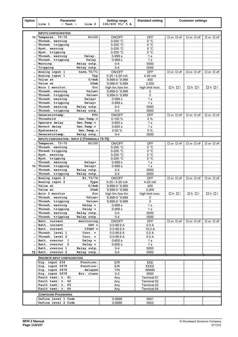
MFR 2 Manual © Woodward Governor Company Page 110/107 37131C
Option Parameter
Line 1 - Text - Line 2 Setting range
100/400 V1/ 5 A Standard setting Customer settings
INPUTS CONFIGURATION
T2 Temperat. 70-72 Pt100 ON/OFF OFF on off on off on off .. Thresh. warning 0-200 °C 0 °C .. Thresh. tripping 0-200 °C 0 °C .. Hyst. warning 0-200 °C 5 °C .. Hyst. tripping 0-200 °C 5 °C .. Thresh. warning Delay. 0-999 s 1 s .. Thresh. tripping Delay 0-999 s 1 s .. Warning Relay outp. 0-4 0000 .. Tripping Relay outp. 0-4 0000 .. Analog input 1 term.70/71 ON/OFF OFF on off on off on off .. Analog input 1 Typ 0-20 / 4-20 mA 4-20 mA .. Value at 0/4mA -9,999-0-+9,999 400 .. Value at 20mA -9,999-0-+9,999 2,000 .. Anin 1 monitor. for high lim./low lim. high limit mon. h l h l h l .. Thresh. warning Value= -9,999-0-+9,999 0 .. Thresh. tripping Value= -9,999-0-+9,999 0 .. Thresh. warning Delay= 0-999 s 1 s .. Thresh. tripping Delay= 0-999 s 1 s .. Thresh. warning Relay outp. 0-4 0000 .. Thresh. tripping Relay outp. 0-4 0000 .. Generatortemp. PTC ON/OFF OFF on off on off on off .. Threshold Gen.Temp.= 0-100 % 0 % .. Operate delay Gen.Temp.= 0-600 s 1 s .. Revert delay Gen.Temp.= 0-600 s 1 s .. Hysteresis Gen.Temp.= 0-50 % 5 % .. Generatortemp. Relay outp. 0-4 0000 .. INPUTS CONFIGRATION - INPUT 2 (TERMINALS 73-75) .. Temperat. 73-75 Pt100 ON/OFF OFF on off on off on off .. Thresh. warning 0-200 °C 0 °C .. Thresh.tripping 0-200 °C 0 °C .. Hyst. warning 0-200 °C 5 °C .. Hyst. tripping 0-200 °C 5 °C .. Thresh. warning Delay= 0-999 s 1 s
T2 Thresh. tripping Delay= 0-999 s 1 s .. Thresh. warning Relay outp. 0-4 0000 .. Thresh. tripping Relay outp. 0-4 0000 .. Analog input 2 Kl.73/74 ON/OFF OFF on off on off on off .. Analog input 2 Type 0-20 / 4-20 mA 4-20 mA .. Value at 0/4mA -9,999-0-+9,999 400 .. Value at 20mA -9,999-0-+9,999 2,000 .. Anin 2 monitor for high lim./low lim. high limit mon. h l h l h l .. Thresh. warning Value= -9,999-0-+9,999 0 .. Thresh. tripping Value= -9,999-0-+9,999 0 .. Thresh. warning Delay = 0-999 s 1 s .. Thresh. tripping Delay = 0-999 s 1 s .. Thresh. warning Relay outp. 0-4 0000 .. Thresh. tripping Relay outp. 0-4 0000 .. Batt. current monitoring ON/OFF OFF on off on off on off .. Batt. current 0mV = 0.0-99.9 A 0.0 A .. Batt. current 150mV = 0.0-99.9 A 10.0 A .. Thresh. level 1 Curr. = 0.0-99.9 A 0.0 A .. Thresh. level 2 Curr. = 0.0-99.9 A 0.0 A .. Batt. overcur 1 Delay = 0-600 s 1 s .. Batt. overcur 2 Delay = 0-600 s 1 s .. Batt. overcur 1 Relay outp. 0-4 0000
T2 Batt. overcur 2 Relay outp. 0-4 0000
DISCRETE INPUT CONFIGURATION Dig. input 234 Function: E/R EEE Dig. input 5678 Function: E/R EEEE Dig. input 5678 delayed Y/N NNNN Dig. input 5678 Err. class 0-3 0000 Fault text: t. 61 Any Terminal 61 Fault text: t. 62 Any Terminal 62 Fault text: t. 63 Any Terminal 63 Fault text: t. 64 Any Terminal 64
CONFIGURE PASSWORDS Define level 1 Code 0-9999 0001 Define level 2 Code 0-9999 0002