METTLER TOLEDO (Edit this in File Properties Title ... · METTLER TOLEDO Publication Revision...
44
D15412200A (9/03).01 86180003 Scoreboard User’s Guide
Transcript of METTLER TOLEDO (Edit this in File Properties Title ... · METTLER TOLEDO Publication Revision...

D15412200A (9/03).01
86180003 Scoreboard User’s Guide
© Mettler-Toledo, Inc. 1997, 1998, 1999, 2002, 2003
No part of this manual may be reproduced or transmitted in any form or by any means, electronic or mechanical, including photocopying and recording, for any purpose without the express written permission of Mettler-Toledo, Inc.
U.S. Government Restricted Rights: This documentation is furnished with Restricted Rights.

METTLER TOLEDO
Publication Revision History An overview of this manual’s revision history is compiled below.
Publication Name: 8618 Scoreboard User’s Guide Publication Part Number: 15412200A Publication Date: 12/97
Part Number Date Revisions A15412200A 2/98 Added Remote Power Supply and Protocol P:20 information.
B15412200A 2/99 Added declaration of conformity. Added dimension drawing of 8618 Scoreboard. Changed input voltage range to 6.5 to 30 VDC. Added information about programming mode change for version 5.10 to Chapter 5.
C15412200A 4/02 Revised information about power requirements for the current model (8618-0002).
D15412200A 2/03 Revised manual to cover new model (8618-0003).
D15412200A(.01) 9/03 Added replacement parts list.
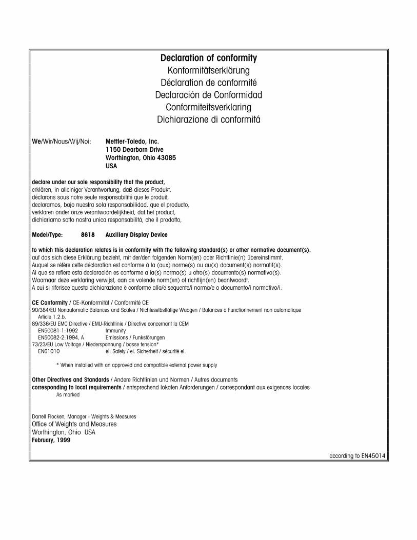
Declaration of conformity Konformitätserklärung
Déclaration de conformité Declaración de Conformidad
Conformiteitsverklaring Dichiarazione di conformitá
We/Wir/Nous/Wij/Noi: Mettler-Toledo, Inc. 1150 Dearborn Drive Worthington, Ohio 43085 USA declare under our sole responsibility that the product, erklären, in alleiniger Verantwortung, daß dieses Produkt, déclarons sous notre seule responsabilité que le produit, declaramos, bajo nuestra sola responsabilidad, que el producto, verklaren onder onze verantwoordelijkheid, dat het product, dichiariamo sotto nostra unica responsabilitá, che il prodotto, Model/Type: 8618 Auxiliary Display Device to which this declaration relates is in conformity with the following standard(s) or other normative document(s). auf das sich diese Erklärung bezieht, mit der/den folgenden Norm(en) oder Richtlinie(n) übereinstimmt. Auquel se réfère cette déclaration est conforme à la (aux) norme(s) ou au(x) document(s) normatif(s). Al que se refiere esta declaración es conforme a la(s) norma(s) u otro(s) documento(s) normativo(s). Waarnaar deze verklaring verwijst, aan de volende norm(en) of richtlijn(en) beantwoordt. A cui si riferisce questa dichiarazione è conforme alla/e sequente/i norma/e o documento/i normativo/i. CE Conformity / CE-Konformität / Conformité CE 90/384/EU Nonautomatic Balances and Scales / Nichteselbsttätige Waagen / Balances à Functionnement non automatique Article 1.2.b. 89/336/EU EMC Directive / EMU-Richtlinie / Directive concernant la CEM EN50081-1:1992 Immunity EN50082-2:1994, A Emissions / Funkstörungen 73/23/EU Low Voltage / Niederspannung / basse tension* EN61010 el. Safety / el. Sicherheit / sécurité el.
* When installed with an approved and compatible external power supply Other Directives and Standards / Andere Richtlinien und Normen / Autres documents corresponding to local requirements / entsprechend lokalen Anforderungen / correspondant aux exigences locales As marked Darrell Flocken, Manager - Weights & Measures Office of Weights and Measures Worthington, Ohio USA February, 1999
according to EN45014

INTRODUCTION This publication is provided solely as a guide for individuals who have received Technical Training in servicing the METTLER TOLEDO product.
Information about METTLER TOLEDO Technical Training can be obtained by writing, calling, or faxing:
METTLER TOLEDO 1900 Polaris Parkway Columbus, Ohio 43240 USA Phone: (614) 438-4511 Fax: (614) 438-4958 www.mt.com
WARNING!
This equipment generates, uses, and can radiate radio frequency energy and, if not installed and used properly, i.e., in accordance with the instructions manual, may cause harmful interference to radio communications. It has been tested and found to comply with the limits for a Class A computing device, pursuant to Subpart J of Part 15 of FCC Rules, which are designed to provide reasonable protection against such interference when operated in a commercial environment. Operation of this equipment in a residential area is likely to cause interference to radio communications, in which case the user at his own expense will be required to take whatever measures may be required to correct the interference.
METTLER TOLEDO RESERVES THE RIGHT TO MAKE REFINEMENTS OR CHANGES WITHOUT NOTICE.

Precautions
WARNING
PERMIT ONLY QUALIFIED PERSONNEL TO SERVICE THIS EQUIPMENT. EXERCISE CARE WHEN MAKING CHECKS, TESTS, AND ADJUSTMENTS THAT MUST BE MADE WITH POWER ON. FAILING TO OBSERVE THESE PRECAUTIONS CAN RESULT IN BODILY HARM.
WARNING
FOR CONTINUED PROTECTION AGAINST SHOCK HAZARD, CONNECT TO PROPERLY GROUNDED OUTLET ONLY. DO NOT REMOVE THE GROUND PRONG.
WARNING
DISCONNECT ALL POWER TO THIS UNIT BEFORE INSTALLING, SERVICING, CLEANING, OR REMOVING THE FUSE. FAILURE TO DO SO COULD RESULT IN BODILY HARM AND/OR PROPERTY DAMAGE.
CAUTION
BEFORE CONNECTING/DISCONNECTING ANY INTERNAL ELECTRONIC COMPONENTS OR INTERCONNECTING WIRING BETWEEN ELECTRONIC EQUIPMENT, ALWAYS REMOVE POWER AND WAIT AT LEAST 30 SECONDS. FAILURE TO OBSERVE THESE PRECAUTIONS COULD RESULT IN BODILY HARM OR DAMAGE TO OR DESTRUCTION OF THE EQUIPMENT.
CAUTION
OBSERVE PRECAUTIONS FOR HANDLING ELECTROSTATIC SENSITIVE DEVICES.
READ this manual BEFORE operating or servicing this equipment. FOLLOW these instructions carefully. SAVE this manual for future reference. DO NOT allow untrained personnel to operate, clean, inspect, maintain, service, or tamper with this equipment. ALWAYS DISCONNECT this equipment from the power source before cleaning or performing maintenance. CALL METTLER TOLEDO for parts, information, and service.
Contents
1 Introduction...................................................................................................1-1 Specifications..................................................................................................................... 1-1
Dimensions ........................................................................................................................ 1-2 Standards Compliance ........................................................................................................ 1-2 New Features ..................................................................................................................... 1-3
2 Installation ...................................................................................................2-1 General.............................................................................................................................. 2-1 Protocol Selection .............................................................................................................. 2-1 Power Supply Connection.................................................................................................... 2-2
DC Power Supply Option....................................................................................................... 2-3 Communication Connections ............................................................................................... 2-4
20 mA CL Connection .......................................................................................................... 2-5 RS-232 Connection ............................................................................................................. 2-5 RS-485 Connection ............................................................................................................. 2-6 20 mA Echo Output ............................................................................................................. 2-7
Mounting ........................................................................................................................... 2-7
3 Scoreboard Behavior......................................................................................3-1 Power-up Sequence ............................................................................................................ 3-1 Time-out ............................................................................................................................ 3-2
4 Setting Operational Parameters ......................................................................4-1 Operational Parameters ...................................................................................................... 4-1 Using the Remote Control ................................................................................................... 4-2 Setting the Address............................................................................................................. 4-3
5 Protocol Selection .........................................................................................5-1 Protocol Selections............................................................................................................. 5-1
Protocol P:20 ..................................................................................................................... 5-1 Standard Protocol ............................................................................................................... 5-3 Supported Protocols............................................................................................................ 5-4
6 Troubleshooting.............................................................................................6-1 Fault Locator ...................................................................................................................... 6-1 Error Messages .................................................................................................................. 6-2
Error Codes......................................................................................................................... 6-3 Checking Received Data...................................................................................................... 6-4
7 Parts Replacement.........................................................................................7-1 Accessing Internal Parts...................................................................................................... 7-1 Replacement Parts.............................................................................................................. 7-2

8 PC Programming Interface .............................................................................8-1 Protocol P:00 ..................................................................................................................... 8-1

Chapter 1: Introduction Specifications
(9/03)
1-1
1 Introduction
The METTLER TOLEDO 86180003 scoreboard is a highly visible weight display for use with vehicle scales and other industrial weighing applications. It displays up to six digits plus the weight unit (lb or kg). The 100-mm (4-inch) digits can be read easily from 30 m (100 feet) away. The scoreboard is designed to operate with METTLER TOLEDO digital indicators that are equipped with continuous serial data output. It can be installed at a location other than where the scale indicator is set up, and it is suitable for use outdoors or in industrial environments.
This manual explains how to install and use a Model 86180003 scoreboard.
Specifications Enclosure: 1.5-mm stainless steel
Front Panel: 4-mm glass or polycarbonate
Environmental Protection: IP65 (NEMA 4X)
Weight: 5.5 kg (12.1 lb)
Cable Glands: PG11, maximum 10-mm cable diameter
Connections: Maximum 10-mm cable for power and data lines
Power: AWG24-AWG14 (0.2-1.5 mm2)
Data Line: AWG25-AWG20 (0.14-0.5 mm2)
Power Input: Universal input 100 to 240 VAC, 50/60 Hz max. 12W
Operating Temperature: -35°C to +45°C (-31°F to +113°F)
Storage Temperature: -40°C to +70°C (-40°F to +158°F)
Serial Interface Card
Communication Speed: 300 to 38,400 baud
Data Bits: 7 or 8*
Parity: None, even, or odd*
Standard Electrical Interfaces: 20 mA current loop, passive input and output fully isolated
RS-232 input fully isolated
RS-422 input non-isolated
RS-485 input or output non-isolated
*NOTE: Do not use a configuration of 7 data bits and no parity. The scoreboard does not support that configuration.
METTLER TOLEDO Model 86180003 Scoreboard User’s Guide
(9/03) 1-2
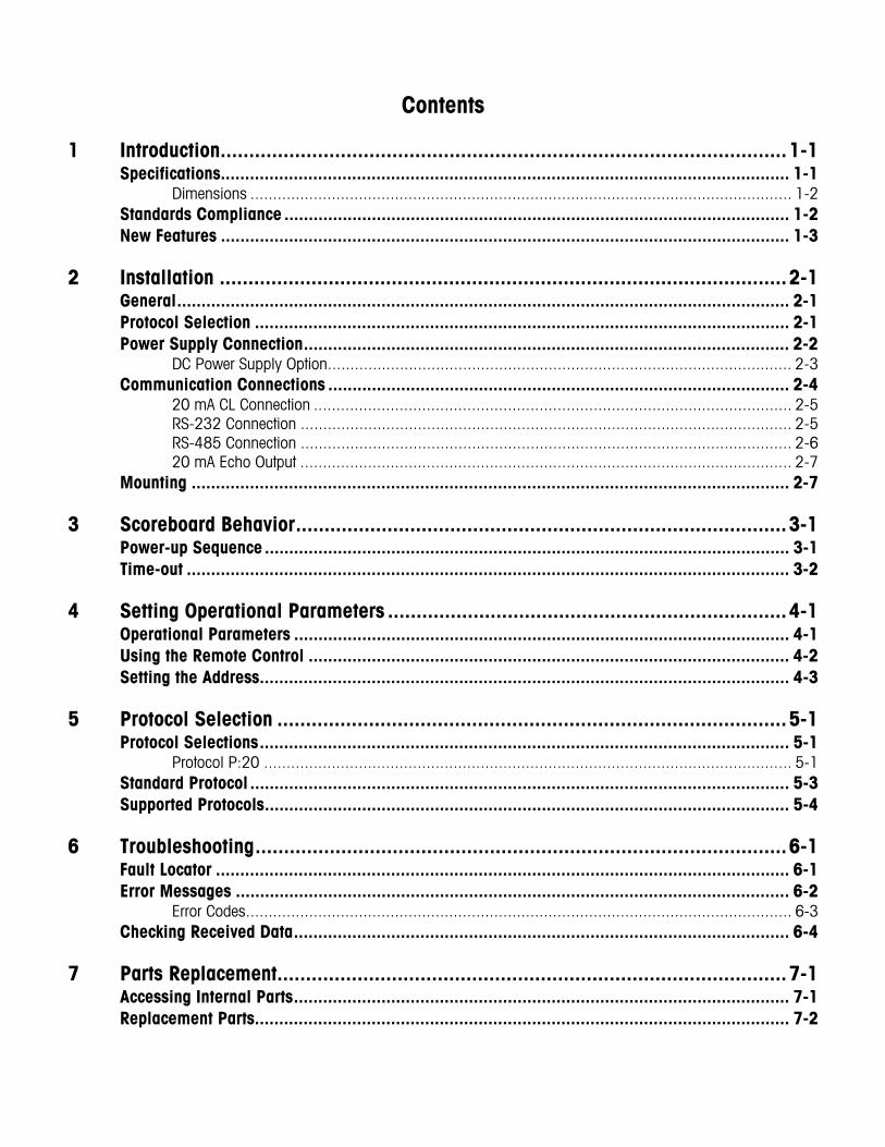
Dimensions Dimensions for the scoreboard are shown in Figure 1-1.
Figure 1-1: 86180003 Scoreboard Dimensions
Standards Compliance
CAUTION ALL APPROVALS AND CERTIFICATES ARE BASED ON CORRECT MOUNTING, GROUNDING, AND CONNECTIONS. ANY DEVIATION MAY RESULT IN UNEXPECTED PERFORMANCE OF THE SYSTEM.
The following compliance standards apply to the 86180003 scoreboard:
Standard Result
EN 50081-1: 1992 Pass
EN 50082-2: 1994 Pass
UL 508 Listed
UL 50 Listed
Underwriters Laboratories: Canadian National Standard Listing investigated to C22.2 No. 142 M1987. United States Standard Listing investigated to UL 508, ed. 17. Tested to Table 6.1 of UL 50 ed. 11 for a Type 4X enclosure. UL report is filed under E232349.
150 mm (5.9 inches)
150 mm (5.9 inches)
Mounting Holes 6.5 mm Diameter
(0.25 inch)
169 mm (6.6 inches)
540 mm (21.2 inches)
65 mm (2.6 inches)
35 mm (1.4 inches)
Chapter 1: Introduction New Features
(9/03)
1-3
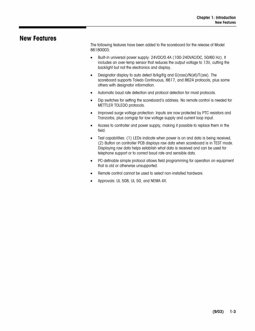
New Features The following features have been added to the scoreboard for the release of Model 86180003:
• Built-in universal power supply: 24VDC/0.4A (100-240VAC/DC, 50/60 Hz). It includes an over-temp sensor that reduces the output voltage to 13V, cutting the backlight but not the electronics and display.
• Designator display to auto detect lb/kg/t/g and G(ross)/N(et)/T(are). The scoreboard supports Toledo Continuous, 8617, and 8624 protocols, plus some others with designator information.
• Automatic baud rate detection and protocol detection for most protocols.
• Dip switches for setting the scoreboard’s address. No remote control is needed for METTLER TOLEDO protocols.
• Improved surge voltage protection: Inputs are now protected by PTC resistors and Tranzorbs, plus comgap for low voltage supply and current loop input.
• Access to controller and power supply, making it possible to replace them in the field.
• Test capabilities: (1) LEDs indicate when power is on and data is being received, (2) Button on controller PCB displays raw data when scoreboard is in TEST mode. Displaying raw data helps establish what data is received and can be used for telephone support or to correct baud rate and sensible data.
• PC-definable simple protocol allows field programming for operation on equipment that is old or otherwise unsupported.
• Remote control cannot be used to select non-installed hardware.
• Approvals: UL 508, UL 50, and NEMA 4X.


Chapter 2: Installation General
(9/03)
2-1
2 Installation
General
CAUTION THE SCOREBOARD AND ITS ASSOCIATED EQUIPMENT MUST BE INSTALLED, ADJUSTED, AND MAINTAINED BY QUALIFIED PERSONNEL WHO ARE FAMILIAR WITH THE CONSTRUCTION AND OPERATION OF ALL EQUIPMENT IN THE SYSTEM AND WITH THE POTENTIAL HAZARDS INVOLVED. FAILURE TO OBSERVE THESE PRECAUTIONS CAN RESULT IN BODILY INJURY AND/OR PROPERTY DAMAGE.
Install the scoreboard in a location that permits access for maintenance and inspection. Locate the scoreboard so that dirt, excessive water, and other harmful materials will not fall on or around the enclosure. Read this manual carefully. If this is your first time installing a scoreboard, we recommend connecting the equipment on a workbench before installing it in the field.
You will need the following tools/materials to install the 8618 scoreboard:
• TORX T20 screwdriver
• 21-mm wrench for cord-grip caps
• Power supply cable with properly grounded plug (20-gauge copper wire, twisted pair, shielded cable)
• Communication cable (20-gauge copper wire, twisted pair, shielded cable)
• Three 6-mm (1/4-inch) screws for mounting scoreboard
• Screwdriver for mounting scoreboard
Protocol Selection If you are connecting the scoreboard to a scale terminal with Toledo Continuous Protocol, you can use the scoreboard’s default operational parameters. If you are connecting to any other instrument, you might need to change the parameters. Please refer to Chapter 4 (Setting Operational Parameters) and Chapter 5 (Protocol Selection). Note the standard setup displayed when you power-up the scoreboard:
XX.XXN Version Number
A:00 Address of the Display 00
P:Auto Automatic Protocol Selected (Factory Default)
C:4800 Baud Rate 4800 (If auto baud found 4800 baud)
P:21 (If auto protocol found Toledo Continuous message format)
If there is any deviation, you will need to edit the operational parameters.
NOTE: After the P:Auto message is displayed, the scoreboard might flash CA while waiting for input.

METTLER TOLEDO Model 86180003 Scoreboard User’s Guide
(9/03) 2-2
Power Supply Connection
WARNING FOR CONTINUED PROTECTION AGAINST SHOCK HAZARD, CONNECT TO PROPERLY GROUNDED OUTLET ONLY. DO NOT REMOVE THE GROUND PRONG.
The scoreboard has a built-in universal input power supply. A properly grounded power supply of 230 or 115 Volts AC is required. You will need to provide a power supply cable (20-gauge copper wire, twisted pair, shielded cable) and connect it to the scoreboard’s junction box. NOTE: A main disconnect is required and shall be provided by the installer.
1. Make sure power is off.
2. Remove the removable cover on the back of the scoreboard (see Chapter 7).
3. Loosen the cord-grip cap next to the power supply terminal strip inside the cover, and insert the end of the power supply cable through the opening in the cap.
4. Wire the cable to the Line, Neutral, and Ground terminals as shown in Figure 2-1.
Figure 2-1: Power Supply Cable Wiring
L
N Connect Power
Supply Cable
Connect Shield from Data Line
NOTE: The power supply terminal strip includes an extra ground terminal for connecting the shield from the data line cable.
Ferrite Ring Data Line Cable
Test Button
Dip Switches
NOTE: Cord grips will accept cables with outer diameters of 5 to 10 mm. For diameters larger than 8 mm, remove the nitrile tube inside the cord grip.
PWR
COM

Chapter 2: Installation Power Supply Connection
(9/03)
2-3
DC Power Supply Option The scoreboard can be run on a DC power supply instead of the internal power supply. To do that, you will need to purchase an external 24V power supply (part number TA100590) and connect it to the scoreboard as shown in Figure 2-2. This external power supply can power up to four scoreboards. Using a DC power supply will allow you to route both the power line and the data line through a single conduit without any interference.
1. Remove the cover on the back of the scoreboard (see Chapter 7).
2. Remove the wires that connect the internal power supply to the controller PCB.
3. Connect the two wires from the external power supply to the controller PCB.
Figure 2-2: DC Power Supply Cable Wiring
PWR
COM
- OUT +
Remove these wires when using DC power supply
V+ (red wire)
0V (black wire) DC Power Supply
(TA100590)
METTLER TOLEDO Model 86180003 Scoreboard User’s Guide
(9/03) 2-4
Communication Connections
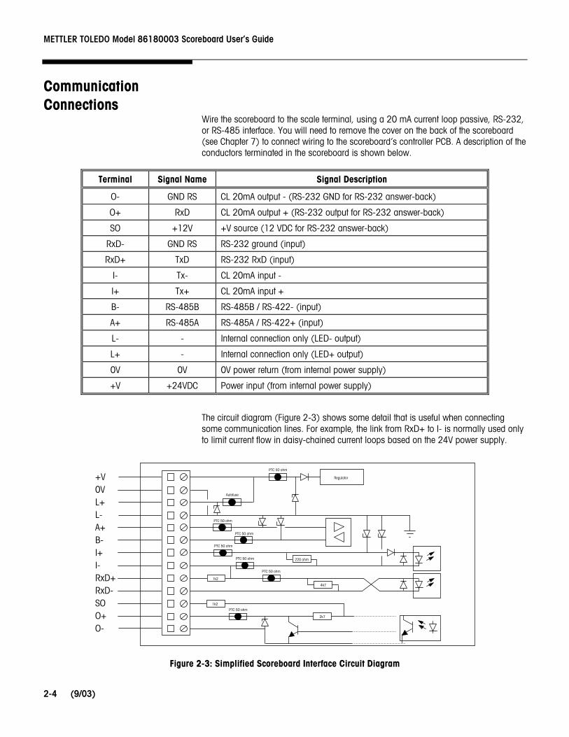
Wire the scoreboard to the scale terminal, using a 20 mA current loop passive, RS-232, or RS-485 interface. You will need to remove the cover on the back of the scoreboard (see Chapter 7) to connect wiring to the scoreboard’s controller PCB. A description of the conductors terminated in the scoreboard is shown below.
Terminal Signal Name Signal Description
O- GND RS CL 20mA output - (RS-232 GND for RS-232 answer-back)
O+ RxD CL 20mA output + (RS-232 output for RS-232 answer-back)
SO +12V +V source (12 VDC for RS-232 answer-back)
RxD- GND RS RS-232 ground (input)
RxD+ TxD RS-232 RxD (input)
I- Tx- CL 20mA input -
I+ Tx+ CL 20mA input +
B- RS-485B RS-485B / RS-422- (input)
A+ RS-485A RS-485A / RS-422+ (input)
L- - Internal connection only (LED- output)
L+ - Internal connection only (LED+ output)
0V 0V 0V power return (from internal power supply)
+V +24VDC Power input (from internal power supply)
The circuit diagram (Figure 2-3) shows some detail that is useful when connecting some communication lines. For example, the link from RxD+ to I- is normally used only to limit current flow in daisy-chained current loops based on the 24V power supply.
Figure 2-3: Simplified Scoreboard Interface Circuit Diagram
+V 0V L+ L- A+ B- I+ I- RxD+ RxD- SO O+ O-
220 ohm
4k7
2k7
1k2
1k2
PTC 50 ohm
PTC 50 ohm
PTC 50 ohm
PTC 50 ohm
PTC 50 ohm
PTC 50 ohm
PTC 50 ohm
Autofuse
Regulator
Chapter 2: Installation Communication Connections
(9/03)
2-5
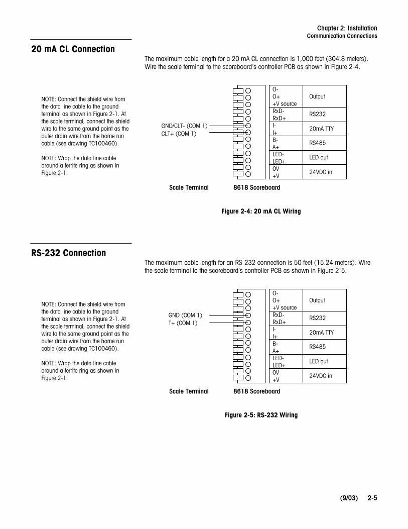
20 mA CL Connection The maximum cable length for a 20 mA CL connection is 1,000 feet (304.8 meters). Wire the scale terminal to the scoreboard’s controller PCB as shown in Figure 2-4.
Figure 2-4: 20 mA CL Wiring
RS-232 Connection The maximum cable length for an RS-232 connection is 50 feet (15.24 meters). Wire the scale terminal to the scoreboard’s controller PCB as shown in Figure 2-5.
Figure 2-5: RS-232 Wiring
GND/CLT- (COM 1) CLT+ (COM 1)
O-O+ +V source RxD- RxD+ I- I+ B- A+ LED- LED+ 0V +V
Scale Terminal 8618 Scoreboard
Output
RS232
20mA TTY
RS485
LED out
24VDC in
GND (COM 1) T+ (COM 1)
O-O+ +V source RxD- RxD+ I- I+ B- A+ LED- LED+ 0V +V
Scale Terminal 8618 Scoreboard
Output
RS232
20mA TTY
RS485
LED out
24VDC in
NOTE: Connect the shield wire from the data line cable to the ground terminal as shown in Figure 2-1. At the scale terminal, connect the shield wire to the same ground point as the outer drain wire from the home run cable (see drawing TC100460). NOTE: Wrap the data line cable around a ferrite ring as shown in Figure 2-1.
NOTE: Connect the shield wire from the data line cable to the ground terminal as shown in Figure 2-1. At the scale terminal, connect the shield wire to the same ground point as the outer drain wire from the home run cable (see drawing TC100460). NOTE: Wrap the data line cable around a ferrite ring as shown in Figure 2-1.

METTLER TOLEDO Model 86180003 Scoreboard User’s Guide
(9/03) 2-6
RS-485 Connection The maximum cable length for an RS-485 connection is 2,000 feet (609.6 meters). Wire the scale terminal to the scoreboard’s controller PCB as shown in Figure 2-6.
Figure 2-6: RS-485 Wiring
Multi-Drop Arrangement
RS-485 allows you to connect as many as five scoreboards in a multi-drop arrangement so that each scoreboard displays a different weight reading. To do that, you must set the operational parameters for P:22 or P:23 protocol and assign a separate address for each scoreboard. Wire the scale terminal to the first scoreboard, and wire each additional scoreboard to the one preceding it (as shown in Figure 2-7).
Figure 2-7: RS-485 Multi-Drop Wiring
• P:22 corresponds to Multi-Continuous 2 on the JAGXTREME terminal. P:23 corresponds to Multi-Continuous 1 on the JAGXTREME terminal
RS-485 T+
RS-485 T-
8618 8618 8618 8618 8618 Scale Terminal
RS-485 B
RS-485 A
RS-485 B
RS-485 A
RS-485 B
RS-485 A
RS-485 B
RS-485 A
RS-485 B
RS-485 A
RS-485 T- / TxD- (COM 2) RS-485 T+ / TxD+ (COM 2)
Scale Terminal 8618 Scoreboard
O-O+ +V source RxD- RxD+ I- I+ B- A+ LED- LED+ 0V +V
Output
RS232
20mA TTY
RS485
LED out
24VDC in
NOTE: Connect the shield wire from the data line cable to the ground terminal as shown in Figure 2-1. At the scale terminal, connect the shield wire to the same ground point as the outer drain wire from the home run cable (see drawing TC100460). NOTE: Wrap the data line cable around a ferrite ring as shown in Figure 2-1.

Chapter 2: Installation Mounting
(9/03)
2-7
20 mA Echo Output You can use the 20 mA output circuit for daisy-chaining scoreboards together. In this type of arrangement, each scoreboard transmits data to the next one in the series so that all scoreboards display the same weight reading. Since a scoreboard does not know how the data enters the processor, you can input data to the first display in any format (RS-232, RS-485, RS-422, 20 mA CL) and redistribute it from the output (Echo) port using the current loop connection. Delay on the line is one byte-time per connected display.
Wire the scale terminal to the first scoreboard, using a 20 mA CL, RS-232, or RS-485 connection (see Figures 2-4, 2-5, and 2-6). Then wire each scoreboard to the next one in the series as shown in Figure 2-8.
Figure 2-8: 20 mA Echo Wiring
Mounting The universal mounting bracket that is supplied with the scoreboard is suitable for ceiling, roof, or wall mounting. Use three 6-mm or 1/4-inch screws to attach the bracket to a rigid surface. Do not mount the scoreboard on a vibrating structure such as machinery. Evaluate the expected torque applied by wind forces to ensure that the scoreboard is mounted safely. The bracket can be attached to the scoreboard with stainless steel bolts M6 x 20 (1.0 mm), using a torque of approximately 10 N·m.
O-O+ +V source RxD- RxD+ I- I+ B- A+ LED- LED+ 0V +V
Output
RS232
20mA TTY
RS485
LED out
24VDC in
O- O+ +V source RxD- RxD+ I- I+ B- A+ LED- LED+ 0V +V
Output
RS232
20mA TTY
RS485
LED out
24VDC in
First Scoreboard Second Scoreboard

Chapter 3: Scoreboard Behavior Power-up Sequence
(9/03)
3-1
3 Scoreboard Behavior
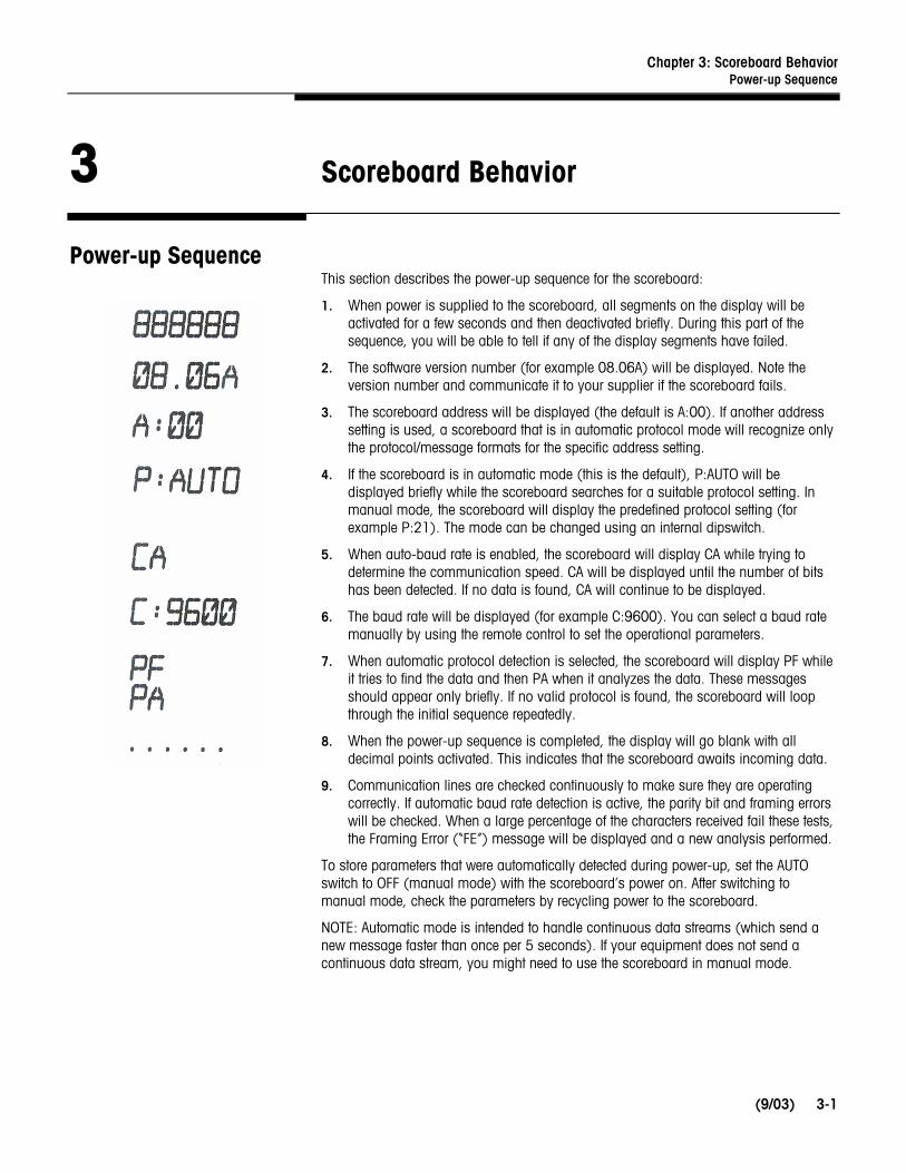
Power-up Sequence This section describes the power-up sequence for the scoreboard:
1. When power is supplied to the scoreboard, all segments on the display will be activated for a few seconds and then deactivated briefly. During this part of the sequence, you will be able to tell if any of the display segments have failed.
2. The software version number (for example 08.06A) will be displayed. Note the version number and communicate it to your supplier if the scoreboard fails.
3. The scoreboard address will be displayed (the default is A:00). If another address setting is used, a scoreboard that is in automatic protocol mode will recognize only the protocol/message formats for the specific address setting.
4. If the scoreboard is in automatic mode (this is the default), P:AUTO will be displayed briefly while the scoreboard searches for a suitable protocol setting. In manual mode, the scoreboard will display the predefined protocol setting (for example P:21). The mode can be changed using an internal dipswitch.
5. When auto-baud rate is enabled, the scoreboard will display CA while trying to determine the communication speed. CA will be displayed until the number of bits has been detected. If no data is found, CA will continue to be displayed.
6. The baud rate will be displayed (for example C:9600). You can select a baud rate manually by using the remote control to set the operational parameters.
7. When automatic protocol detection is selected, the scoreboard will display PF while it tries to find the data and then PA when it analyzes the data. These messages should appear only briefly. If no valid protocol is found, the scoreboard will loop through the initial sequence repeatedly.
8. When the power-up sequence is completed, the display will go blank with all decimal points activated. This indicates that the scoreboard awaits incoming data.
9. Communication lines are checked continuously to make sure they are operating correctly. If automatic baud rate detection is active, the parity bit and framing errors will be checked. When a large percentage of the characters received fail these tests, the Framing Error (“FE”) message will be displayed and a new analysis performed.
To store parameters that were automatically detected during power-up, set the AUTO switch to OFF (manual mode) with the scoreboard’s power on. After switching to manual mode, check the parameters by recycling power to the scoreboard.
NOTE: Automatic mode is intended to handle continuous data streams (which send a new message faster than once per 5 seconds). If your equipment does not send a continuous data stream, you might need to use the scoreboard in manual mode.

METTLER TOLEDO Model 86180003 Scoreboard User’s Guide
(9/03) 3-2
Time-out There are two time-outs used with the scoreboard: long and short.
• The long time-out fully resets the scoreboard whenever there has been no communication activity for approximately 4 minutes. The time-out period is normally reset for each valid message received.
• The short time-out blanks the screen to indicate that there has been no activity for 6-9 seconds. In response to a short time-out, the display goes blank and the protocol is initiated according to the parameter settings.
Both types of time-out are enabled for all advanced protocols (P:21, 22, 23). All protocols have the short time-out enabled as a fixed parameter and cannot be effectively changed. Only protocol P:20 can have the short time-out disabled (by using the remote control). P:20 protocol does not use the long time-out.
Chapter 4: Setting Operational Parameters Operational Parameters
(9/03)
4-1
4 Setting Operational Parameters
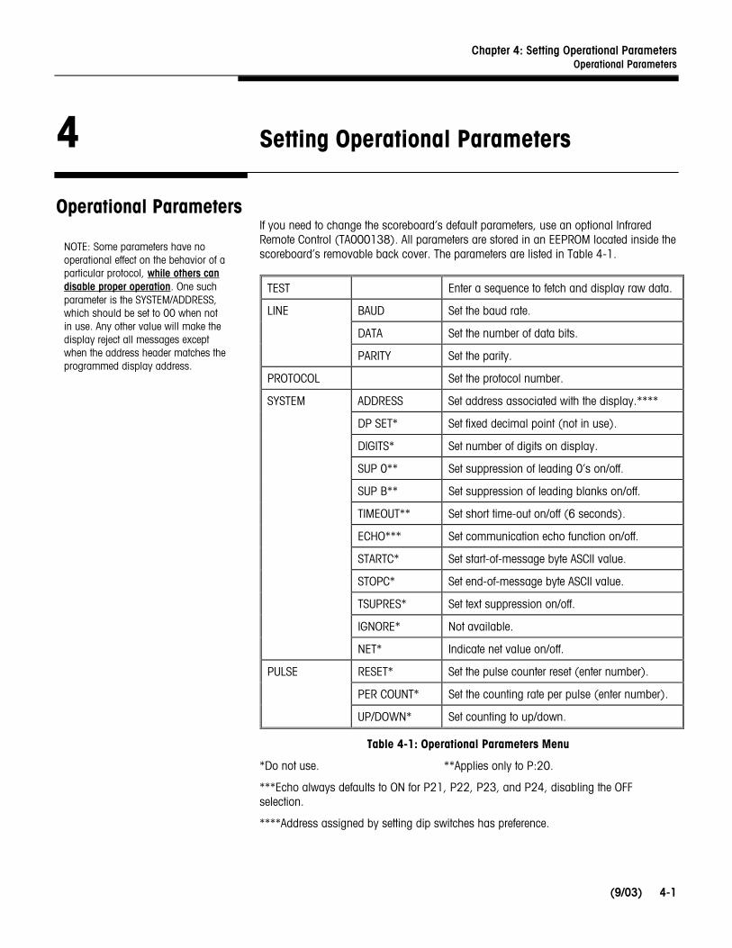
Operational Parameters If you need to change the scoreboard’s default parameters, use an optional Infrared Remote Control (TA000138). All parameters are stored in an EEPROM located inside the scoreboard’s removable back cover. The parameters are listed in Table 4-1.
TEST Enter a sequence to fetch and display raw data.
LINE BAUD Set the baud rate.
DATA Set the number of data bits.
PARITY Set the parity.
PROTOCOL Set the protocol number.
SYSTEM ADDRESS Set address associated with the display.****
DP SET* Set fixed decimal point (not in use).
DIGITS* Set number of digits on display.
SUP 0** Set suppression of leading 0’s on/off.
SUP B** Set suppression of leading blanks on/off.
TIMEOUT** Set short time-out on/off (6 seconds).
ECHO*** Set communication echo function on/off.
STARTC* Set start-of-message byte ASCII value.
STOPC* Set end-of-message byte ASCII value.
TSUPRES* Set text suppression on/off.
IGNORE* Not available.
NET* Indicate net value on/off.
PULSE RESET* Set the pulse counter reset (enter number).
PER COUNT* Set the counting rate per pulse (enter number).
UP/DOWN* Set counting to up/down.
Table 4-1: Operational Parameters Menu
*Do not use. **Applies only to P:20.
***Echo always defaults to ON for P21, P22, P23, and P24, disabling the OFF selection.
****Address assigned by setting dip switches has preference.
NOTE: Some parameters have no operational effect on the behavior of a particular protocol, while others can disable proper operation. One such parameter is the SYSTEM/ADDRESS, which should be set to 00 when not in use. Any other value will make the display reject all messages except when the address header matches the programmed display address.

METTLER TOLEDO Model 86180003 Scoreboard User’s Guide
(9/03) 4-2
Using the Remote Control
The remote control uses an infrared signal to program the scoreboard. Effective range of operation for the remote control is 8 inches. For software version 5.10 or later, the programming mode is disabled during normal operation. To enable it, you will need to disconnect the data line before using the remote control. You will also need to enter Manual mode by setting the AUTO dip switch to the OFF position.
1. Remove the cover on the back of the scoreboard (see Chapter 7).
2. To set parameters, point the remote control at the receiver on the scoreboard’s controller PCB (see Figure 4-1). Press the remote control’s «OPEN» button several times until the display responds with CodE0.
3. Press the programmed 4-digit code (usually 0000) to open the parameters menu.
4. Use the arrow buttons to traverse through the menu and the «YES» button to select an option. The «NO» button will return you to the previous menu item or end the set-up procedure.
When pressing «YES» to make a selection, the currently active value will be displayed. Use the arrow buttons to scroll through the other possible values or type the required parameter number. Press the «YES» button to accept the new choice. There is not a ‘Cancel’ button, so please program with care. All new parameters take effect immediately after normal operation is resumed.
5. To exit the programming mode, press the «NO» button repeatedly until End and Err.11 are displayed. The system will automatically restart.
Notes on Infrared Remote Control Operation
Pressing the OPEN button while holding down the SHIFT button will force the program to “END” and automatically restart.
When using the remote control, be sure to protect other nearby scoreboards from the infrared signal by shielding the units or removing power from them.
The infrared receiver located on the scoreboard’s controller PCB might be sensitive to certain frequencies emitted from artificial light sources. If the display is operated with the control board exposed to light sources, the following symptoms might occur: intermittent error code and intermittent restart.
Figure 4-1: Infrared Receiver on Controller PCB
PWR
COM
Point Remote Control Here

Chapter 4: Setting Operational Parameters Setting the Address
(9/03)
4-3
Setting the Address The factory default address setting for the scoreboard is 0. For some installations, you will need to change the address setting, for example, when you connect several scoreboards in a multi-drop arrangement. The dip switches on the scoreboard’s controller PCB can be used to set the address (see Figure 4-2).
Use switches 2, 3, 4, and 5 to set the scoreboard’s address. A value is assigned to each switch (switch 5 = 1, switch 4 = 2, switch 3 = 4, and switch 2 = 8). Table 4-2 shows how to set the switches for addresses 0 to 6. Switch 1 (AUTO) is used to turn the Automatic Protocol Mode on and off. If AUTO mode is on, the scoreboard will determine communication and protocol selections at power-up. Switching the AUTO mode off while the power is on will save the current setup and force the scoreboard to use the current baud rate and protocol selection.
Pressing the TEST push button allows you to enter a visual communication text mode (see Chapter 6 for more information).
Figure 4-2: Dip Switches
Address Switch 5 Switch 4 Switch 3 Switch 2
0 OFF OFF OFF OFF
1 ON OFF OFF OFF
2 OFF ON OFF OFF
3 ON ON OFF OFF
4 OFF OFF ON OFF
5 ON OFF ON OFF
6 OFF ON ON OFF
Table 4-2: Dip Switch Settings
Use for setting the address
TEST Button
AUTO
ON
1 2 3 4 5


Chapter 5: Protocol Selection Protocol Selections
(9/03)
5-1
5 Protocol Selection
Protocol Selections Protocols are provided to support all widely used METTLER TOLEDO instruments and related systems. Select the protocol that matches the scale terminal or other instrument connected to the scoreboard (refer to Table 5-1).
Protocol Instrument Description
P:20 Computer Simple protocol – Receives ASCII text data from a computer
P:21 MT Continuous Data Default setting, no address (A:00)
P:22 MT 8624 Multi-drop format Addressed (A:01 to 05)
P:23 MT 8617 Multi-drop format Addressed (A:01 to 05)
P:24 MT ID Series No address (A:00)
Table 5-1: Protocols for the 86180003 Scoreboard
Protocol P:20 Protocol P:20 sets the scoreboard to receive a simple ASCII string.
The scoreboard has six digits and can display a maximum of six characters from a host device. The data received is filtered so that only specific data will be displayed. The valid data are the ASCII characters: <0>, <1>, <2>, <3>, <4>, <5>, <6>, <7>, <8>, <9>, <-> minus sign, <.> decimal point, and <,> comma. No other ASCII characters will be displayed. Any display characters transmitted before the minus sign will be ignored. One decimal point or comma may be transmitted between any two numeric characters. So you could display a date using a decimal point delimiter, for example, <08.14.02>. A minus sign is displayed left justified and text is displayed right justified. The comma and decimal point both turn on the same element on the display.
The data format is <STX>DDDDDD<CR>, where D is a numeric ASCII character (0 to 9). When the minus sign is used, there is a maximum of 5 numeric ASCII characters. To blank out the scoreboard in the P:20 protocol, omit data characters in the transmit string: <STX><CR>.
TSUPRES option (this is always enabled, so it is not really optional)
Text suppression (filtering): All invalid text characters are discarded; however, valid text received after invalid text will overwrite the receive buffer.
METTLER TOLEDO Model 86180003 Scoreboard User’s Guide
(9/03) 5-2
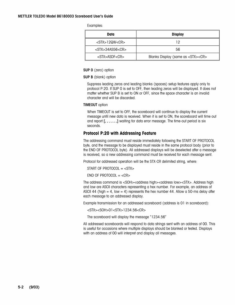
Examples:
Data Display
<STX>12QW<CR> 12
<STX>34AS56<CR> 56
<STX>ASDF<CR> Blanks Display (same as <STX><CR>
SUP 0 (zero) option
SUP B (blank) option
Suppress leading zeros and leading blanks (spaces) setup features apply only to protocol P:20. If SUP 0 is set to OFF, then leading zeros will be displayed. It does not matter whether SUP B is set to ON or OFF, since the space character is an invalid character and will be discarded.
TIMEOUT option
When TIMEOUT is set to OFF, the scoreboard will continue to display the current message until new data is received. When it is set to ON, the scoreboard will time out and report [, , , , , ,] waiting for data error message. The time-out period is six seconds.
Protocol P:20 with Addressing Feature
The addressing command must reside immediately following the START OF PROTOCOL byte, and the message to be displayed must reside in the same protocol body (prior to the END OF PROTOCOL byte). All addressed displays will be deselected after a message is received, so a new addressing command must be received for each message sent.
Protocol for addressed operation will be the STX-CR delimited string, where:
START OF PROTOCOL = <STX>
END OF PROTOCOL = <CR>
The address command is <SOH><address high><address low><STX>. Address high and low are ASCII characters representing a hex number. For example, an address of ASCII 44 (high = 4, low = 4) represents the hex number 44. Allow a 50-ms delay after each message to an addressed display.
Example transmission for an addressed scoreboard (address is 01 in scoreboard):
<STX><SOH>01<STX>1234.56<CR>
The scoreboard will display the message “1234.56”
All addressed scoreboards will respond to data strings sent with an address of 00. This is useful for occasions where multiple displays should be blanked or tested. Displays with an address of 00 will interpret and display all messages.
Chapter 5: Protocol Selection Standard Protocol
(9/03)
5-3
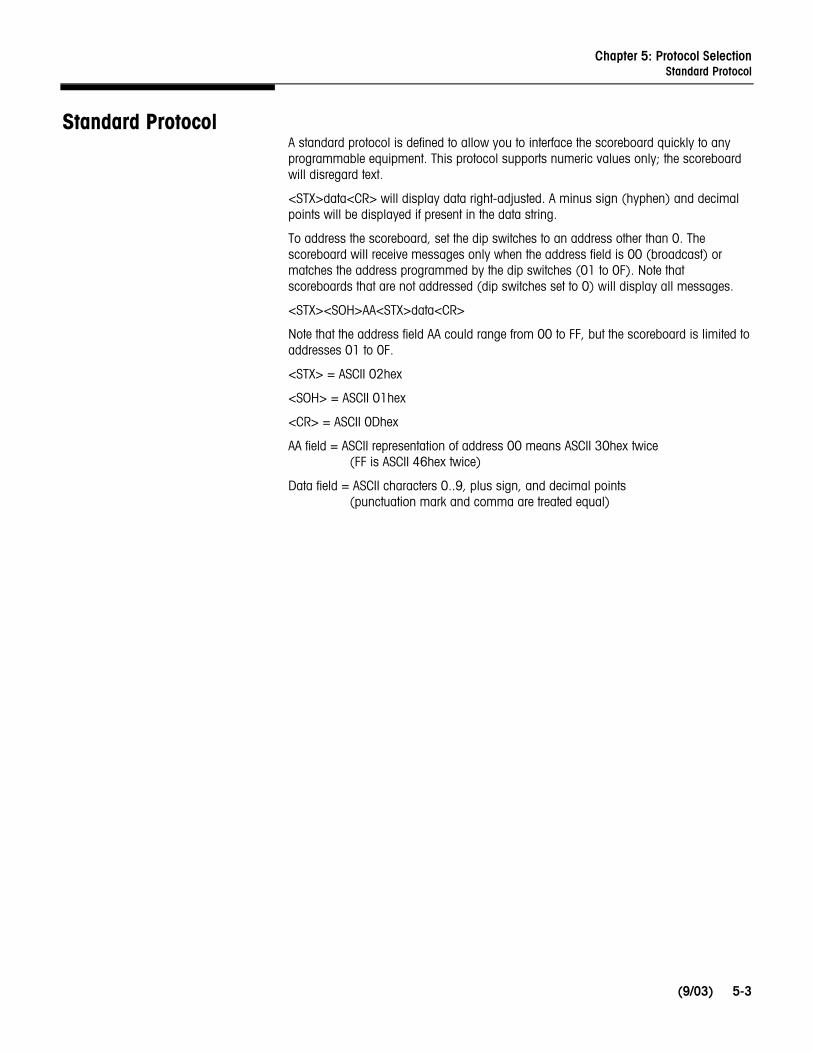
Standard Protocol A standard protocol is defined to allow you to interface the scoreboard quickly to any programmable equipment. This protocol supports numeric values only; the scoreboard will disregard text.
<STX>data<CR> will display data right-adjusted. A minus sign (hyphen) and decimal points will be displayed if present in the data string.
To address the scoreboard, set the dip switches to an address other than 0. The scoreboard will receive messages only when the address field is 00 (broadcast) or matches the address programmed by the dip switches (01 to 0F). Note that scoreboards that are not addressed (dip switches set to 0) will display all messages.
<STX><SOH>AA<STX>data<CR>
Note that the address field AA could range from 00 to FF, but the scoreboard is limited to addresses 01 to 0F.
<STX> = ASCII 02hex
<SOH> = ASCII 01hex
<CR> = ASCII 0Dhex
AA field = ASCII representation of address 00 means ASCII 30hex twice (FF is ASCII 46hex twice)
Data field = ASCII characters 0..9, plus sign, and decimal points (punctuation mark and comma are treated equal)

METTLER TOLEDO Model 86180003 Scoreboard User’s Guide
(9/03) 5-4
Supported Protocols The scoreboard has been designed to interface with various scale terminals and other instruments. The following table lists the instruments that are supported and the protocol number for each. Contact the manufacturer for updated information.
Manufacturer & Model Auto or Manual
Protocol Number
Manufacturer & Model Auto or Manual
Protocol Number
A&D INSTRUMENTS • AD-4326/27 AMBER • WI-3, WI-6, WI-10 AVERY-BERKEL • WG-4 • WG-4 Inverted • Standard String #3 • L115/117/215/217 • L130 • L210 • Loadstar XL18 CARDINAL • 748 Continuous CONSOLIDATED CONTROLS • Standard EILON ENGINEERING • Standard FLINTAB • 47-04 Standard • 47-10 Standard GARVENS • STD Format 2 GASSNER • DMA 02 Junior GLOBAL/PHILIPS • PR 1577 Mode • PR 1720 Mode • PR 1628 GSE SCALE SYSTEMS • Model 350, 550 HAENNI • Standard LASER MIKE • Model 940
M
M A M A A A M A A A
M
A/M A/M
M A
M M M
M
M
M
P25
P44
P32 P33 P34 P20 P34 P30 P20
P45
P41
P10
P40 P40
P20
P42
P26 P26 P26
P51
P53/P07
P58/P07
LEON ENGINEERING • LDS 5204-06 continuous MANTRA ELECTRONICS • Task 120 METTLER TOLEDO • Toledo Continuous • 8624/MultiCont2 • 8617/MultiCont1 • ID Series • SICS (v. 08.16) • Simple ASCII Format • WinBridge MOLEN WEIGHT • Simple Format NORSK DISPLAY • Standard • Addressed • Demo • Counter PIVOTEX • Standard Consolidated PRECIA MOLEN • Type I (9 byte) RAUTE PRECISION • WB-900 RICE LAKE WEIGHING SYSTEM • Standard SARTORIUS • SBI 16 & 22 bytes S-E-G • Standard THURMAN SCALE • 465 Indicator TRAYVOU • T6000 Indicator
A
M A A A
A/M A
A/M M
M A A M M A A
M A A
M A A
P70
P52
P21
P22** P23** P24 P28 P20 P27
P47
P20
P20** P54..P57
P60
P41
P47
P10
P41
P59
P60
P41
P71
** With this protocol, you must use the internal switch array to set the scoreboard’s address to something other than 00.
Chapter 6: Troubleshooting Fault Locator
(9/03)
6-1
6 Troubleshooting
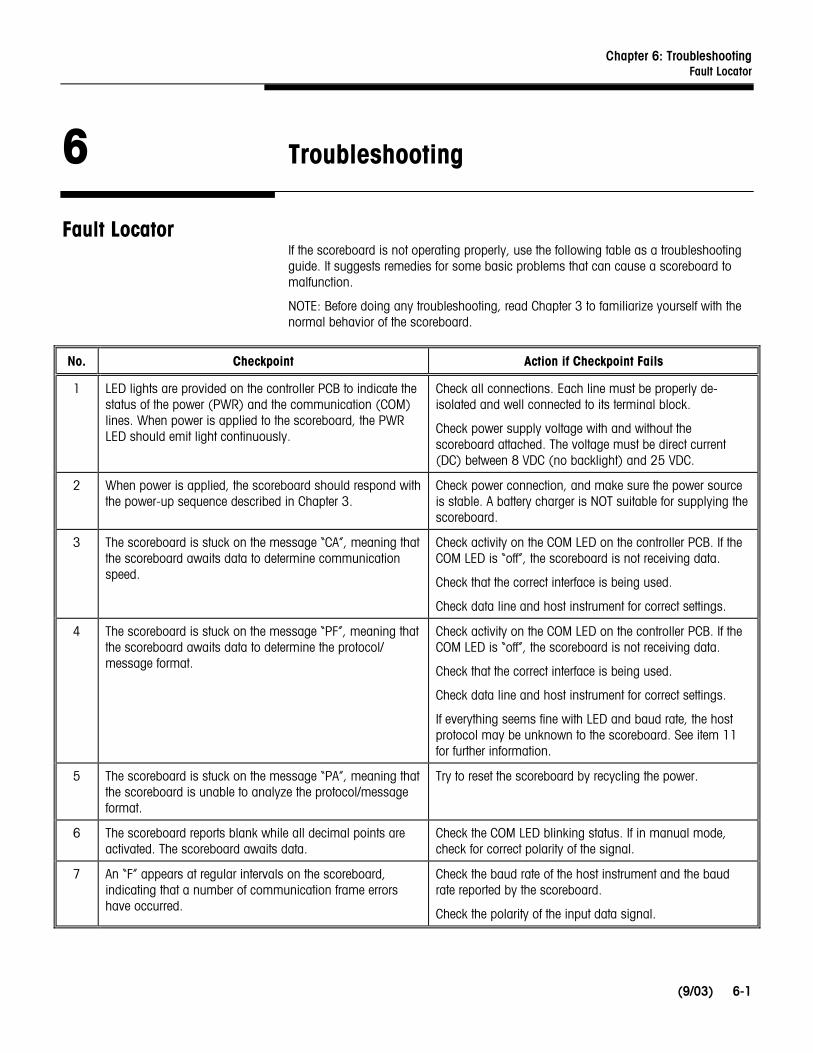
Fault Locator If the scoreboard is not operating properly, use the following table as a troubleshooting guide. It suggests remedies for some basic problems that can cause a scoreboard to malfunction.
NOTE: Before doing any troubleshooting, read Chapter 3 to familiarize yourself with the normal behavior of the scoreboard.
No. Checkpoint Action if Checkpoint Fails
1 LED lights are provided on the controller PCB to indicate the status of the power (PWR) and the communication (COM) lines. When power is applied to the scoreboard, the PWR LED should emit light continuously.
Check all connections. Each line must be properly de-isolated and well connected to its terminal block.
Check power supply voltage with and without the scoreboard attached. The voltage must be direct current (DC) between 8 VDC (no backlight) and 25 VDC.
2 When power is applied, the scoreboard should respond with the power-up sequence described in Chapter 3.
Check power connection, and make sure the power source is stable. A battery charger is NOT suitable for supplying the scoreboard.
3 The scoreboard is stuck on the message “CA”, meaning that the scoreboard awaits data to determine communication speed.
Check activity on the COM LED on the controller PCB. If the COM LED is “off”, the scoreboard is not receiving data.
Check that the correct interface is being used.
Check data line and host instrument for correct settings.
4 The scoreboard is stuck on the message “PF”, meaning that the scoreboard awaits data to determine the protocol/ message format.
Check activity on the COM LED on the controller PCB. If the COM LED is “off”, the scoreboard is not receiving data.
Check that the correct interface is being used.
Check data line and host instrument for correct settings.
If everything seems fine with LED and baud rate, the host protocol may be unknown to the scoreboard. See item 11 for further information.
5 The scoreboard is stuck on the message “PA”, meaning that the scoreboard is unable to analyze the protocol/message format.
Try to reset the scoreboard by recycling the power.
6 The scoreboard reports blank while all decimal points are activated. The scoreboard awaits data.
Check the COM LED blinking status. If in manual mode, check for correct polarity of the signal.
7 An “F” appears at regular intervals on the scoreboard, indicating that a number of communication frame errors have occurred.
Check the baud rate of the host instrument and the baud rate reported by the scoreboard.
Check the polarity of the input data signal.
METTLER TOLEDO Model 86180003 Scoreboard User’s Guide
(9/03) 6-2
No. Checkpoint Action if Checkpoint Fails
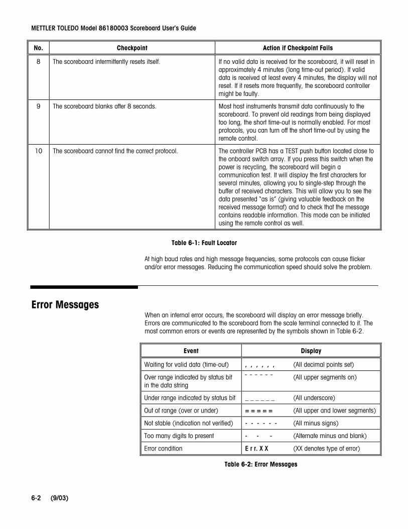
8 The scoreboard intermittently resets itself. If no valid data is received for the scoreboard, it will reset in approximately 4 minutes (long time-out period). If valid data is received at least every 4 minutes, the display will not reset. If it resets more frequently, the scoreboard controller might be faulty.
9 The scoreboard blanks after 8 seconds. Most host instruments transmit data continuously to the scoreboard. To prevent old readings from being displayed too long, the short time-out is normally enabled. For most protocols, you can turn off the short time-out by using the remote control.
10 The scoreboard cannot find the correct protocol. The controller PCB has a TEST push button located close to the onboard switch array. If you press this switch when the power is recycling, the scoreboard will begin a communication test. It will display the first characters for several minutes, allowing you to single-step through the buffer of received characters. This will allow you to see the data presented “as is” (giving valuable feedback on the received message format) and to check that the message contains readable information. This mode can be initiated using the remote control as well.
Table 6-1: Fault Locator
At high baud rates and high message frequencies, some protocols can cause flicker and/or error messages. Reducing the communication speed should solve the problem.
Error Messages When an internal error occurs, the scoreboard will display an error message briefly. Errors are communicated to the scoreboard from the scale terminal connected to it. The most common errors or events are represented by the symbols shown in Table 6-2.
Event Display
Waiting for valid data (time-out) , , , , , , (All decimal points set)
Over range indicated by status bit in the data string
¯ ¯ ¯ ¯ ¯ ¯ (All upper segments on)
Under range indicated by status bit _ _ _ _ _ _ (All underscore)
Out of range (over or under) = = = = = (All upper and lower segments)
Not stable (indication not verified) - - - - - - (All minus signs)
Too many digits to present - - - (Alternate minus and blank)
Error condition E r r. X X (XX denotes type of error)
Table 6-2: Error Messages
Chapter 6: Troubleshooting Error Messages
(9/03)
6-3
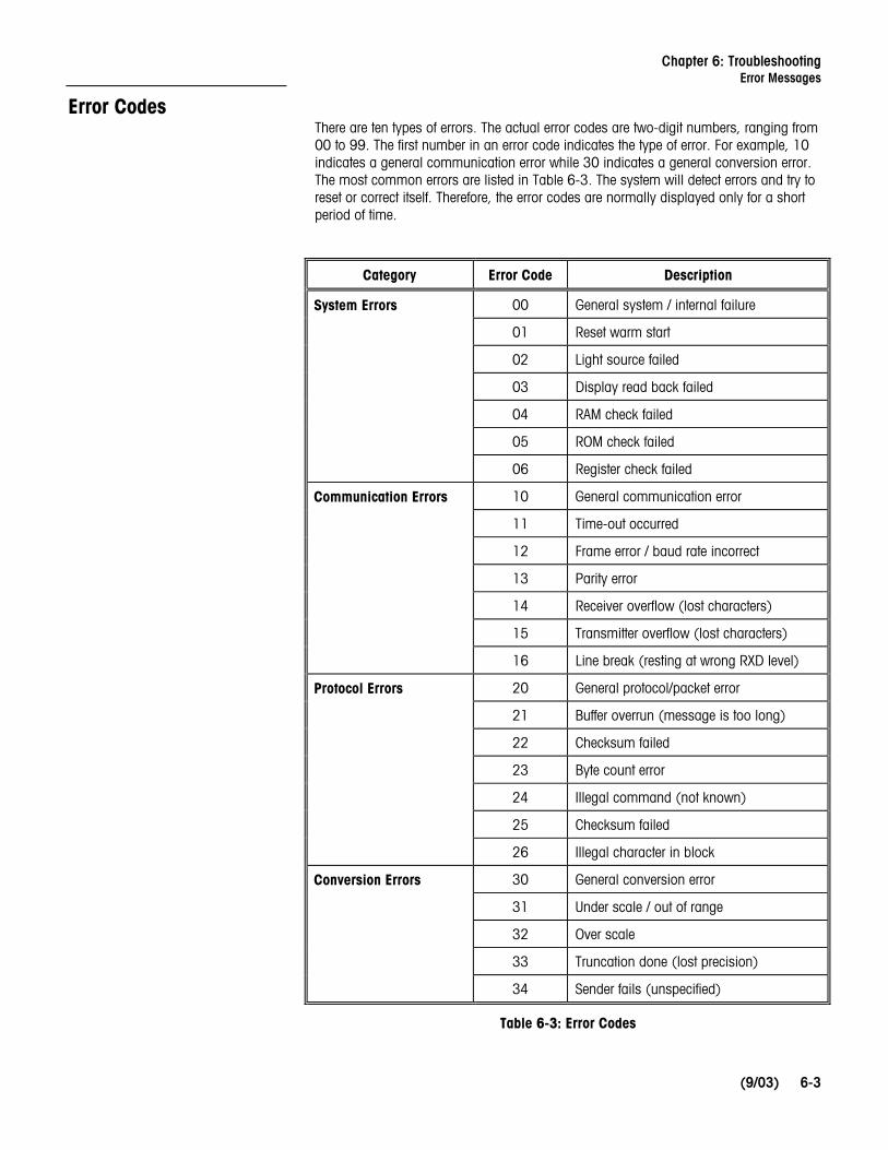
Error Codes There are ten types of errors. The actual error codes are two-digit numbers, ranging from 00 to 99. The first number in an error code indicates the type of error. For example, 10 indicates a general communication error while 30 indicates a general conversion error. The most common errors are listed in Table 6-3. The system will detect errors and try to reset or correct itself. Therefore, the error codes are normally displayed only for a short period of time.
Category Error Code Description
00 General system / internal failure
01 Reset warm start
02 Light source failed
03 Display read back failed
04 RAM check failed
05 ROM check failed
System Errors
06 Register check failed
10 General communication error
11 Time-out occurred
12 Frame error / baud rate incorrect
13 Parity error
14 Receiver overflow (lost characters)
15 Transmitter overflow (lost characters)
Communication Errors
16 Line break (resting at wrong RXD level)
20 General protocol/packet error
21 Buffer overrun (message is too long)
22 Checksum failed
23 Byte count error
24 Illegal command (not known)
25 Checksum failed
Protocol Errors
26 Illegal character in block
30 General conversion error
31 Under scale / out of range
32 Over scale
33 Truncation done (lost precision)
Conversion Errors
34 Sender fails (unspecified)
Table 6-3: Error Codes

METTLER TOLEDO Model 86180003 Scoreboard User’s Guide
(9/03) 6-4
Checking Received Data
WARNING PERMIT ONLY QUALIFIED PERSONNEL TO SERVICE THIS EQUIPMENT. EXERCISE CARE WHEN MAKING CHECKS, TESTS, AND ADJUSTMENTS THAT MUST BE MADE WITH POWER ON. FAILING TO OBSERVE THESE PRECAUTIONS CAN RESULT IN BODILY HARM.
Most problems can be traced to the scoreboard’s power supply and communication lines. The following information explains how to visually inspect the status of the scoreboard to locate a problem without using test equipment.
There are two Light Emitting Diodes (LEDs) on the scoreboard’s controller PCB. When the power supply is operating properly, the PWR diode will be lit. When the scoreboard is receiving data, the COM diode will be blinking. If the power supply is operating properly, the source of the problem is probably the data cable, connection, or message format. To check these further, you need to be sure that data is continuously sent from the instrument or PC that is connected to the scoreboard.
1. If the COM diode is not blinking, check the data line connections.
• Try to switch polarity.
• If current loop is used, make sure it is actively transmitting (or connect a 20 mA source to the data line).
2. Activate the communication test by pressing the TEST push button located on the scoreboard’s controller PCB while power is being recycled. The scoreboard will display the message “FETCH” while it retrieves the data and then will display the received characters “00-20” (00 is the position and 20 is the actual hexadecimal data). You need to be able to understand hexadecimal data or to communicate this information to a qualified service technician. Pressing the TEST button will allow you to see each byte that is received. If 4 minutes passes without the TEST button being used, the scoreboard will reset.
You can also access the communication test function without opening the scoreboard’s removable cover. Use the IR remote control to access the TEST selection on the menu, and then press the «YES» button. The only difference is that the scoreboard will automatically step through the data for 4 minutes. NOTE: Make sure the baud rate is set properly before accessing the TEST selection with the remote control.
3. Use the data to evaluate the baud rate and protocol. Contact a qualified service technician for help.
Chapter 7: Parts Replacement Accessing Internal Parts
(9/03)
7-1
7 Parts Replacement
Accessing Internal Parts
WARNING PERMIT ONLY QUALIFIED PERSONNEL TO SERVICE THIS EQUIPMENT. EXERCISE CARE WHEN MAKING CHECKS, TESTS, AND ADJUSTMENTS THAT MUST BE MADE WITH POWER ON. FAILING TO OBSERVE THESE PRECAUTIONS CAN RESULT IN BODILY HARM.
WARNING DISCONNECT ALL POWER TO THIS UNIT BEFORE INSTALLING, SERVICING, CLEANING, OR REMOVING THE FUSE. FAILURE TO DO SO COULD RESULT IN BODILY HARM AND/OR PROPERTY DAMAGE.
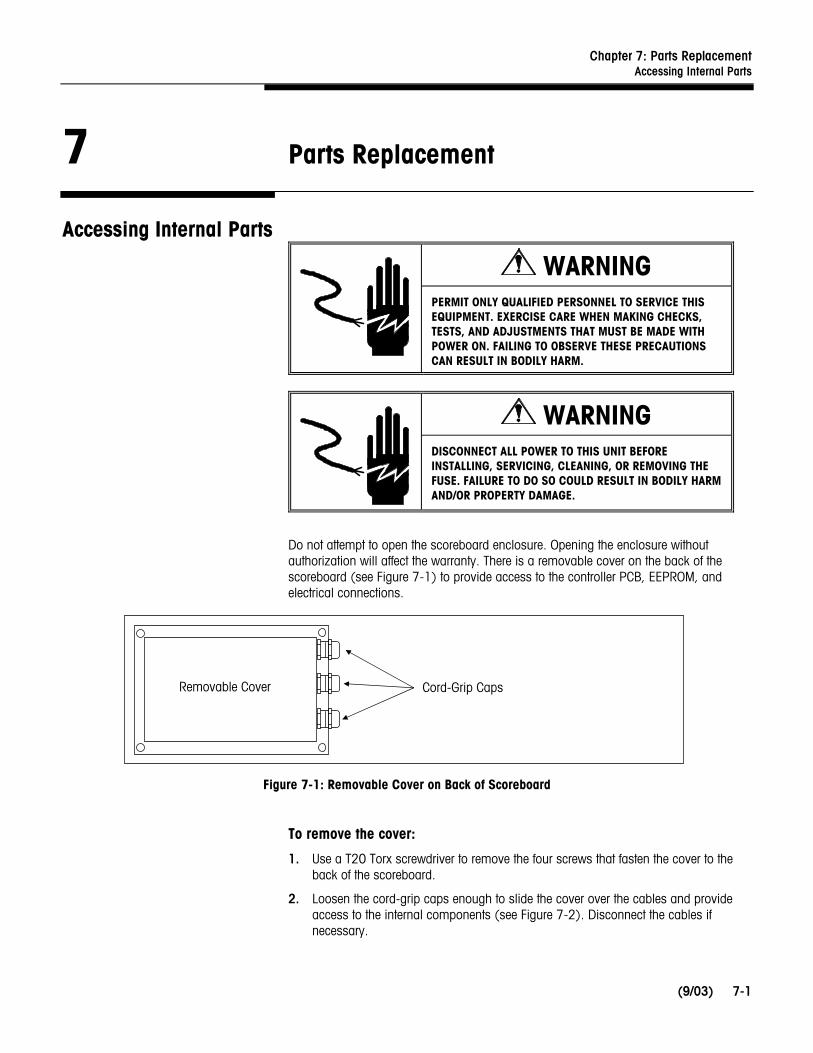
Do not attempt to open the scoreboard enclosure. Opening the enclosure without authorization will affect the warranty. There is a removable cover on the back of the scoreboard (see Figure 7-1) to provide access to the controller PCB, EEPROM, and electrical connections.
Figure 7-1: Removable Cover on Back of Scoreboard
To remove the cover:
1. Use a T20 Torx screwdriver to remove the four screws that fasten the cover to the back of the scoreboard.
2. Loosen the cord-grip caps enough to slide the cover over the cables and provide access to the internal components (see Figure 7-2). Disconnect the cables if necessary.
Removable Cover Cord-Grip Caps

METTLER TOLEDO Model 86180003 Scoreboard User’s Guide
(9/03) 7-2
Figure 7-2: Cord Grip Cap
To reinstall the cover:
1. Attach any cables that were loosened.
2. Reposition the cover, making sure that the cables are not squeezed in between the cover and the enclosure.
3. Replace the four screws and tighten them with the T20 Torx screwdriver.
4. Tighten the cord-grip caps and make sure that all seals are secure.
When operating in a dusty or wet environment, please take all possible precautions to prevent dust particles or water droplets from remaining inside the removable cover after servicing. Contamination and humidity may harm the electronics.
Replacement Parts The following table lists the replacement parts that are available for the 86180003 scoreboard.
Part Number Description Quantity
MZ0302000116 Controller PCB 1
MZ0302000117 Power Supply PCB 1
MZ0302000118 Full Back Cover (includes gasket and screws) 1
MZ0302000121 Gasket and Screws 1
MZ0302000122 Mounting Bracket 1
TA000138 IR Remote Control 1
Insert Cable Removable Cover
Detail of Cord-Grip Cap
Chapter 8: PC Programming Interface Protocol P:00
(9/03)
8-1
8 PC Programming Interface
Protocol P:00 To allow you to field program the scoreboard, there are a number of built-in tools you can use to prepare a new instrument to be interfaced. A special protocol number (P:00) is designed to be a flexible interpreter for normal serial text formats. By using the P:00 protocol, you should be able to capture the values transmitted by almost any host instrument.
With the available free software for Windows™ 95/98 from Norsk Display AS, you can tailor the scoreboard behavior using the procedure listed below. Note that you will have to physically access the controller PCB to permanently store the selection.
1. Make sure the controller is in Auto mode (factory default).
2. Connect the scoreboard to a PC and power it up.
3. Start the PC program “NDConfig” or any suitable terminal program.
4. Select the correct serial port, scoreboard, and instrument type.
5. Press the “Read Display” button if necessary.
6. The scoreboard should respond by displaying “Prog”.
7. If the display does not respond, press the “Read Display” button.
8. You can now edit the main parameter window.
9. Set each parameter, or pull down the manufacturer’s list for predefined values.
10. Press the “Prog” button in NDConfig and follow the instructions.
11. Make sure that all parameters are accepted.
12. Set the scoreboard in Manual mode (AUTO dip switch is in OFF position). This will save the settings and force the scoreboard to use the programmed features.
The scoreboard behavior for serial setup is briefly described to allow parameter changes by using a terminal or to enable OEM customers to produce their own control program.
Programming mode is accessed by sending a continuous “<Esc>P” sequence after power-up. The scoreboard will respond by displaying “Prog” and transmitting the string “<lf>OK” using the CL output. The serial data response may be discarded, but will provide a valuable feedback for automated, sequenced programming. Every command is issued with an allowed response time for feedback: “<lf>OK” when command is judged valid and “<lf>*ERR” for invalid commands. As an additional service, the scoreboard will display “Error” if the last processed command contained illegal characters or sequences. Only capital letters are allowed in commands, while string parameters are processed as is. Note that every key pressed on a terminal is sent to the scoreboard, and editing (backspace, etc.) is not supported.
All commands are terminated by a CR (Carriage Return ASCII 13dec).

METTLER TOLEDO Model 86180003 Scoreboard User’s Guide
(9/03) 8-2
GLOBAL INFLUENCE
Command Syntax Description Valid Parameters [Default]
Status Request S Status request will dump all programmable settings to the serial output.
No parameters
Communication Speed C=<number> Sets the communication baud rate.
00 (=Auto), 300 to 38,400 [00=Auto]
Communication Data Bits D=<number> Sets the number of data bits. “7” or “8” [7]
Communication Parity P=<character> Sets the parity scheme. N(one), E(ven), O(dd) [E]
Manual Protocol Select MP=<hexnumber> Allows you to set the protocol interpreter. Note that only MP=00 will override the switch array Auto mode setting, while all other protocol numbers will be active only in Manual mode (AUTO dip switch is in OFF position).
“00” to “FF” [20]
Note the ASCII hex representation. MP=20 represents STX-data-CR message format.
Scoreboard Address A=<number> Sets the scoreboard address for some special protocols. Switch array settings override this software setting. Used only for special protocols.
“00” to “99”
Address is programmed and reported in decimals
Time-Out Period TO=<number> Number of seconds before display is blanked and protocol interpreter is re-initiated. Note that many protocols have a fixed setting of this time-out.
“0” to “99” [10]
“0” disables the time-out
Time-out is approximately 8 seconds
Request String RS=<string> Request string defines the string or single character to send back to the host instrument (for example, to initiate transmission). The request string is sent 1 second before time-out. Most protocols do not require a request string to be used.
String, max. 10 characters
Use ^ prior to a printable character to denote a CTRL-character (for example, ^A is ASCII 00h)
Chapter 8: PC Programming Interface Protocol P:00
(9/03)
8-3
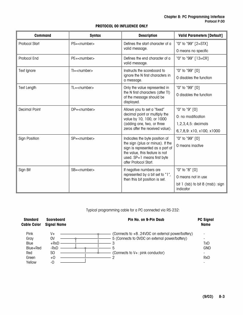
PROTOCOL 00 INFLUENCE ONLY
Command Syntax Description Valid Parameters [Default]
Protocol Start PS=<number> Defines the start character of a valid message.
“0” to “99” [2=STX]
0 means no specific
Protocol End PE=<number> Defines the end character of a valid message.
“0” to “99” [13=CR]
Text Ignore TI=<number> Instructs the scoreboard to ignore the N first characters in a message.
“0” to “99” [0]
0 disables the function
Text Length TL=<number> Only the value represented in the N first characters (after TI) of the message should be displayed.
“0” to “99” [0]
0 disables the function
Decimal Point DP=<number> Allows you to set a “fixed” decimal point or multiply the value by 10, 100, or 1000 (adding one, two, or three zeros after the received value).
“0” to “9” [0]
0: no modification
1,2,3,4,5: decimals
6,7,8,9: x10, x100, x1000
Sign Position SP=<number> Indicates the byte position of the sign (plus or minus). If the sign is represented as a part of the value, this feature is not used. SP=1 means first byte after Protocol Start.
“0” to “99” [0]
0 means inactive
Sign Bit SB=<number> If negative numbers are represented by a bit set to “1”, then this bit position is set.
“0” to “8” [0]
0 means not in use
bit 1 (lsb) to bit 8 (msb): sign indicator
Typical programming cable for a PC connected via RS-232:
Pink Gray Blue Blue+Red Red Green Yellow
V+ 0V +RxD -RxD SO +O -O
- - TxD GND - RxD -
(Connects to +8..24VDC on external power/battery) 5 (Connects to 0VDC on external power/battery) 3 5 (Connects to V+: pink conductor) 2
Standard Cable Color
Scoreboard Signal Name
Pin No. on 9-Pin Dsub PC Signal Name

METTLER TOLEDO
Publication Suggestion Report If you have suggestions concerning this publication, please complete this form and fax it to (614) 841-7295
Publication Name: METTLER TOLEDO 86180003 Scoreboard User’s Guide Publication Part Number: D15412200A Publication Date: 9/03
PROBLEM(S) TYPE: DESCRIBE PROBLEM(S): INTERNAL USE ONLY
� Technical Accuracy � Text � Illustration
� Completeness � Procedure/step � Illustration � Definition � Information in What information is missing? � Example � Guideline � Feature manual � Explanation � Other (please explain below) � Information not in manual
� Clarity
What is not clear?
� Sequence
What is not in the right order?
� Other Comments
Use another sheet for additional comments.
Your Name: Location:
Phone Number: ( )
Mettler-Toledo, Inc. Printed in USA 14981600A
Fax this completed form to METTLER TOLEDO at (614) 841-7295


METTLER TOLEDO 1900 Polaris Parkway Columbus, Ohio 43240 USA P/N: D15412200A (9/03) METTLER TOLEDO® is a registered trademark of Mettler-Toledo, Inc. © 1997, 1998, 1999, 2002, 2003 Mettler-Toledo, Inc. Printed in USA
D15412200A