
Metso Microwave Consistency...
74
Metso Microwave Consistency Transmitter Installation, Operating & Service manual OUL00298 V2.2 EN
Transcript of Metso Microwave Consistency...

Metso Microwave Consistency Transmitter
Installation, Operating& Service manual
OUL00298 V2.2 EN

Table of contents
Caution / Warning
Introduction 71.
General............................................................71.1.
Structure 92.
MCA-F..............................................................92.1.MCA-FT............................................................92.2.Sensor Electronics ........................................122.3.Transmitter Central Unit (TCU) .....................122.4.
Installation 133.
General principles..........................................133.1.Choosing the installation site.........................133.2.Sensor dimensions.........................................173.3.Mounting dimensions.....................................193.4.Transmitter Central Unit (TCU) and shield.....203.5.Electrical Connections ...................................203.6.Metso MCA-F Sensor Deflector Plate InstallationGuide..............................................................22
3.7.
Setting Up 234.
Mechanical Inspection....................................234.1.Installation......................................................234.2.Cabling Inspection..........................................234.3.Electrical Inspection.......................................234.4.Configuration and Calibration........................234.5.
User Interface and Operation 255.
Transmitter Central Unit.................................255.1.Operations Menu............................................265.2.
Configuration 276.
Configuration menu........................................276.1.Choosing and scaling the output signal.........276.2.User Settings..................................................276.3.Device information ........................................286.4.Setting the date and time...............................286.5.Address..........................................................286.6.
Calibration 297.
Sample Taking................................................297.1.Entering Laboratory Results..........................307.2.Offset Correction............................................307.3.Fillers..............................................................307.4.Calibration and sample history ......................317.5.
Diagnostics 338.
Error Table......................................................338.1.Diagnostics Values.........................................338.2.Diagnostics Limits..........................................338.3.
Special Functions 359.
Chemical compensation.................................359.1.Sensitivity Correction.....................................389.2.Recipes..........................................................399.3.
Troubleshooting 4110.
Troubleshooting.............................................4110.1.Process Conditions........................................4110.2.Self-diagnostics error messages....................4310.3.
Replacing Components 4511.
Sensor Electronics.........................................4511.1.Antenna cables, Fork Sensor.........................4611.2.Antenna Cables, FT Sensor...........................4811.3.Antennas, Fork Sensor..................................4911.4.Antennas, FT Sensor.....................................4911.5.TCU ...............................................................5011.6.Installing Vortex Cooler..................................5011.7.
HART® User Interface 5112.
About the interface.........................................5112.1.Measurement.................................................5212.2.Configure........................................................5212.3.Calibrate.........................................................5312.4.Diagnostics.....................................................5712.5.
Upgrade Kit for MCAi 5913.
Structure.........................................................5913.1.Electrical connections....................................5913.2.Installation Guide - Upgrade Kit for MCAi......6013.3.Startup............................................................6313.5.Configuration and Calibration........................6313.6.User Interface.................................................6313.7.Troubleshooting and Maintenance.................6313.8.
Recycling and disposing of a device re-moved from service 65
14.
Technical Specifications
Service kits & Spare parts
Installation, operating & service manual OUL00298 V2.2 EN3Metso Mircowave Consistency Transmitter

Installation, operating & service manual OUL00298 V2.2 EN4Metso Mircowave Consistency Transmitter
Caution / Warning
During installation, maintenance and service operations, remember thatthe sample line may contain hot sample or water – be careful!
Always check that the incoming voltage & frequency are correct beforemaking any electric connections. Wrong connection may damage theequipment! The applicable electrical safety regulations must be closelyfollowed in all installation work!
Before any welding works in the vicinity of the devices, make sure thatoperating voltage is not connected!
Installation, operating & service manual OUL00298 V2.2 EN5Metso Mircowave Consistency Transmitter

Installation, operating & service manual OUL00298 V2.2 EN6Metso Mircowave Consistency Transmitter

1. Introduction1.1. GeneralMetso Mircowave Consistency Transmitter (MetsoMCA) functions based on the measurement of mi-crowave propagation time.
Microwaves are electromagnetic radiation; the flyingtime depends on the media's dielectric constant. Flyingtime is calculated as follows:
c = speed of light in a vacuumer = media's dielectric constant
In water microwaves advance at a much slower speedthat in wood fiber. Therefore, consistency can be calcu-lated based on the time it takes the microwaves to movethrough the measured mass.
The advantages of this measurement procedure arepulp type-independence, insensitivity to flow speed,and single-point calibration.
There are two different models of Metso MCA sensors:- Metso MCA-F Fork sensor (figure 2).- Metso MCA-FT Flow-through sensors (figure 3).
Metso MCA also includes a user interface known asTransmitter Central Unit (TCU) (figure 1).
Fig. 1. Transmitter Central Unit (TCU).
Fig. 2. Metso MCA-F.
Fig. 3. Metso MCA-FT.
Installation, operating & service manual OUL00298 V2.2 EN7Metso Mircowave Consistency Transmitter

Notes
Installation, operating & service manual OUL00298 V2.2 EN8Metso Mircowave Consistency Transmitter

2. StructureMetso MCA comprises the sensor unit and a user inter-face called Transmitter Central Unit. There are twosensor models: MCA-F Fork Sensor and MCA-FTFlow-Through Sensor, which come in six differentsizes ranging from FT-50 to FT-300. The appropriatemodel is selected according to the diamater of the pro-cess pipe.
2.1. MCA-FIn the fork-type MCA-F sensor, the microwave anten-nas are mounted on the sensor body, which is installedvia a coupling into the process pipe. On the end of thesensor there is a probe antenna and on the base thereis a flushmounted antenna. In addition, on the end ofthe sensor body there is a Pt-100 thermoelement. Theantenna cables and the Pt-100 sensor cables run throughthe inside of the sensor to the sensor electronics.Figure3 shows the sensor's construction drawing.
The material of the wetted metal parts is AISI316L,with options of titanium or hastelloy. The antenna ma-terial is polished ceramic.
1
2 3
4
Fig. 1. Metso MCA-F: 1. Pt-100 Thermoelement, 2.Microwave Antennas, 3. Sensor Electronics, 4. SensorCable Connector.
2.2. MCA-FTThe body of the Flow-Through sensor is a pipe, which,when installed, replaces an identical length of processpipe. Flush-mounted antennas are installed on oppositesides of the sensor body, so measurement takes placethrough the pipe. The sensor electronics casings is in-stalled on the sensor body by means of a connectingpipe. The Pt-100 sensor, which measures process tem-perature, is installed inside the connecting pipe. Theantenna cables, which are protected within casing, runto the base plate of the electronics casing on the outsideof the connecting pipe. Figure 4 shows the sensor'sconstruction drawing.
The material of the wetted sensor and antenna bodiesis AISI 316/316L. The antenna material is polishedceramic.
1
2
3
4
5
Fig. 2. Metso MCA-FT: 1. Sensor Electronics, 2. SensorCable Connector, 3. Antenna Cable, 4. Pt-100 Ther-moelement, 5. Microwave Antennas.
Installation, operating & service manual OUL00298 V2.2 EN9Metso Mircowave Consistency Transmitter

Fig. 3. Metso MCA-F construction drawing: 1. Microwave Antenna, 2. Sensor Head, 3. Pt-100 Thermoelement,4. Antenna Cables, 5. Sensor Body, 6. Antenna Sealing, 7. Fixing Clamp, 8. Base Plate Assembly, 9. SensorElectronics, 10. Sensor Cover.
Installation, operating & service manual OUL00298 V2.2 EN10Metso Mircowave Consistency Transmitter

Fig. 4. Metso MCA-FT construction drawing: 1. Sensor Cover, 2. Sensor Electronics, 3. Base Plate Assembly, 4.Pt-100 Thermoelement, 5. Sensor Body, 6. Antenna Sealing, 7. Microwave Antenna, 8. Antenna Flange, 9. AntennaCable, 10. Antenna Cover.
Installation, operating & service manual OUL00298 V2.2 EN11Metso Mircowave Consistency Transmitter
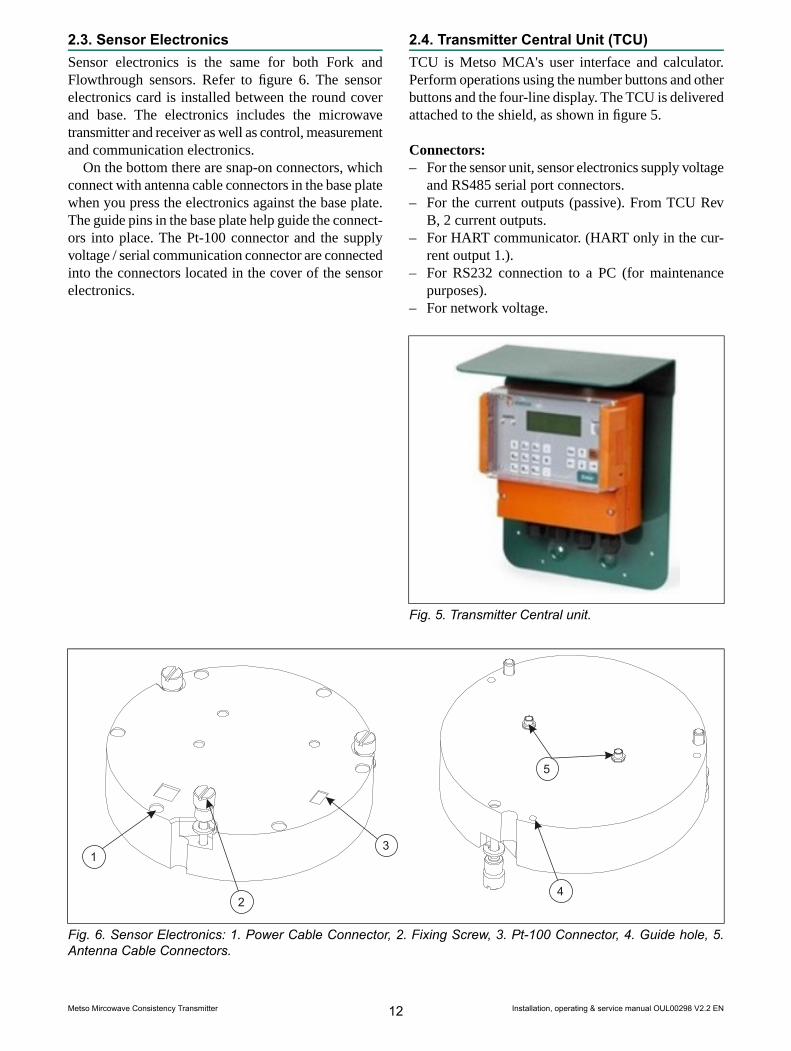
2.3. Sensor ElectronicsSensor electronics is the same for both Fork andFlowthrough sensors. Refer to figure 6. The sensorelectronics card is installed between the round coverand base. The electronics includes the microwavetransmitter and receiver as well as control, measurementand communication electronics.
On the bottom there are snap-on connectors, whichconnect with antenna cable connectors in the base platewhen you press the electronics against the base plate.The guide pins in the base plate help guide the connect-ors into place. The Pt-100 connector and the supplyvoltage / serial communication connector are connectedinto the connectors located in the cover of the sensorelectronics.
2.4. Transmitter Central Unit (TCU)TCU is Metso MCA's user interface and calculator.Perform operations using the number buttons and otherbuttons and the four-line display. The TCU is deliveredattached to the shield, as shown in figure 5.
Connectors:– For the sensor unit, sensor electronics supply voltage
and RS485 serial port connectors.– For the current outputs (passive). From TCU Rev
B, 2 current outputs.– For HART communicator. (HART only in the cur-
rent output 1.).– For RS232 connection to a PC (for maintenance
purposes).– For network voltage.
Fig. 5. Transmitter Central unit.
1
2
3
4
5
Fig. 6. Sensor Electronics: 1. Power Cable Connector, 2. Fixing Screw, 3. Pt-100 Connector, 4. Guide hole, 5.Antenna Cable Connectors.
Installation, operating & service manual OUL00298 V2.2 EN12Metso Mircowave Consistency Transmitter

3. Installation3.1. General principlesThe sensor model is selected according to the size ofthe pipe. Flow-through models are FT50/2", FT100/4",FT150/6", FT200/8", FT250/10", and FT300/12".Flowthrough models can be installed on the followingpipe flanges:
– DIN PN10– DIN PN16– ANSI Class 150– JIS 10K
In laboratory analysis of measurement results it isimportant to use a proper sampler (e.g. NOVE). Installit according to MCA installation instructions.
NOTE! Before installing the process coupling or sensor,check that the process pipe is empty and unpressurizedand that installation is safe.
3.2. Choosing the installation siteThe fork-type Metso MCA-F sensor can be installedon pipes with a diameter of 150 mm (6") or larger. Inchoosing an installation position, note the following:– It is not recommended to install Metso MCA-F
sensor in a place where the pulp may contain strings,etc., that may get wrapped around the sensor. If ne-cessary, use a separate deflector plate.
– Do not install the sensor on the pump's suction sideor in the mixing tank.
– After the sensor there should be a straight sectionof pipe, length at least 2 times the pipe diameter,before a change in pipe profile.
– Adjacent to Metso MCA-F sensor or one meter be-fore it there must not be objects inserted into thepipe.
– Reserve enough space for the sensor casing. For theMetso MCA-F, reserve also space required forsensor installation.
– The TCU must be installed within 10 meters of thesensor. The sensor cable is 10m long. You also havethe option of purchasing a 30m sensor cable.
In addition, you must note the following specifications:– Process temperature under 100 °C.– pH range 2.5...11.5.– Conductivity according to sensor specifications.– Recommended process pressure is 1.5 - 25 bar (Fork
sensor) / 16 bar (FT sensor) to eliminate the effectof air bubbles.
– Sensor pressure tolerance:• Fork sensor PN25• FT sensor PN16
Installation checklist:– Check that the mounting location and position are
in accordance with the installation instructions.– Check that the flow arrow on the sensor casing is
pointing in the direction of flow.– Protect the sensor and the TCU from direct heat
sources and sunlight.– Metso MCA-F: Before operating the sensor, check
that the process coupling's mounting clamp is se-curely tightened.
– Metso MCA-FT: Before operating the sensor, checkthat the sealing between the MCA flanges and pro-cess flanges are properly installed and that themounting nuts are tightened.
Sensor installation to a vertical and horizontalpipeline is illustrated in Fig. 1 - 5.
Installation, operating & service manual OUL00298 V2.2 EN13Metso Mircowave Consistency Transmitter

Fig. 1. Metso MCA-F Installation on a vertical pipe: A. after a pump, B. after a horizontal pipe.
Fig. 2. Metso MCA-F Installation on a horizontal pipe: A. after a vertical pipe, B. after a bend in the pipe.
Installation, operating & service manual OUL00298 V2.2 EN14Metso Mircowave Consistency Transmitter

Fig. 3. Metso MCA-FT Installation on a vertical pipe: A. after a pump, B. after a horizontal pipe.
Fig. 4. Metso MCA-FT Installation on a horizontal pipe: A. after a bend in the pipe, B. after a vertical pipe.
Installation, operating & service manual OUL00298 V2.2 EN15Metso Mircowave Consistency Transmitter

Fig. 5. Metso MCA-FT installation directly after a pump.
Fig. 6. Metso MCA-FT installation directly after a pump.
Installation, operating & service manual OUL00298 V2.2 EN16Metso Mircowave Consistency Transmitter
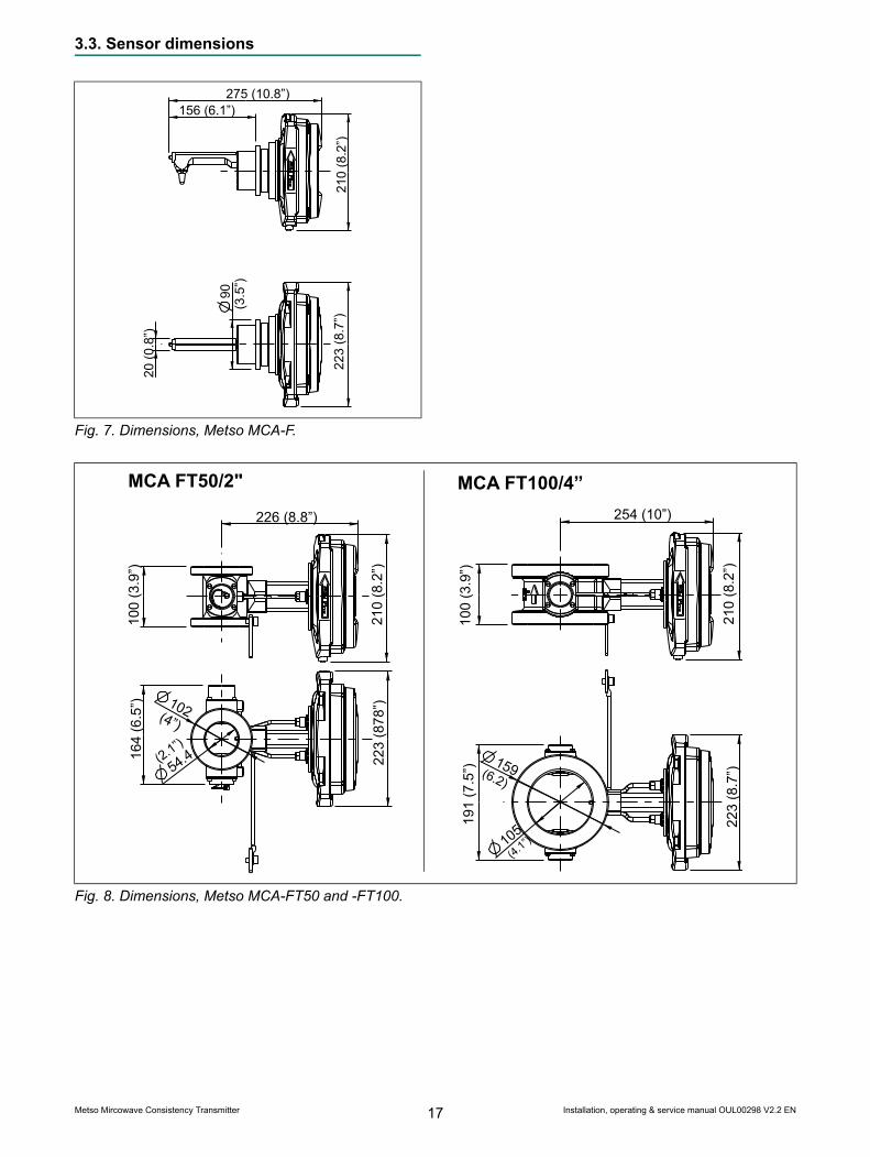
3.3. Sensor dimensions
223(8.7”)
275 (10.8”)156 (6.1”)
20(0.8”)
210(8.2”)
9(3.5”)0
Fig. 7. Dimensions, Metso MCA-F.
223(878”)
210(8.2”)
226 (8.8”)
100(3.9”)
164(6.5”) 1
(4”)02
54(2.1”).4
MCA FT50/2"
223(8.7”)
159(6.2)
191(7.5”)
254 (10”)
210(8.2”)
100(3.9”)
MCA FT100/4”
1(4.1”)
05
Fig. 8. Dimensions, Metso MCA-FT50 and -FT100.
Installation, operating & service manual OUL00298 V2.2 EN17Metso Mircowave Consistency Transmitter

223(8.7”)
223(8.7”)
215(8.5”)
280 (11”)
270(10.6”)
100
304 (12”)
210(8.2”)
210(8.2”)
225(8.8”)
100(3.9”)
100(3.9”)
MCA FT150/6" MCA FT200/8"
155(6.
1”)
203(8”)
Fig. 9. Dimensions, Metso MCA-FT150 and -FT200.
MCA FT250/10" MCA FT300/12"
223(8.7”)
320(12.5”)
120
(4.7”)
330 (12.9”)
210(8.2”)
255
(8.8”) 22
3(8.7”)
(12”)
120
370(14.5”)
355 (14”)
(4.7”)
210(8.2”)
305
Fig. 10. Dimensions, Metso MCA-FT250 and -FT300.
Installation, operating & service manual OUL00298 V2.2 EN18Metso Mircowave Consistency Transmitter

3.4. Mounting dimensionsMetso MCA-FThe fork-type Metso MCA-F sensor is installed in aprocess coupling welded onto the side of the processpipe in such a way that the probe antenna is directedagainst the direction of the flow (Fig. 11). The sensoris loosely tightened into place with mounting clampsand then approximately aligned with the pipe based onthe position of the electronics casing. After aligning,tighten the mounting clamps to their final tightness.The sticker on the electronics casing indicates the in-stallation direction in relation to the direction of flow.
NOTE: The probe antenna on the end of the sensor isceramic, so avoid denting it.
FLOW
6.14"156
4.69"119
8.27"
210
min. 500 mm (20")
Fig. 11. Metso MCA-F Mounting dimensions.
Metso MCA-FTWhen installed, the flow-through sensor replaces thecorresponding length of process pipe (Fig. 12). Thesticker on the electronics casing indicates the installa-tion direction in relation to the direction of flow. Thesensors do not include flanges, but rather they aretightened with stud bolts between flanges mounted onthe process pipe.
L
MIN. 500 mm (20")
Fig. 12. Metso MCA-FT Mounting dimensions.
Installation, operating & service manual OUL00298 V2.2 EN19Metso Mircowave Consistency Transmitter

3.5. Transmitter Central Unit (TCU) and shieldThe TCU is delivered attached to the shield. The shieldis attached to the wall with three mounting screws ina place that is easily accessed.
When selecting a place for the TCU, remember thatthe sensor cable is 10 m long. Figure 13 shows shieldmounting dimensions.
3.6. Electrical Connections
NOTE:When connecting the power supply cables, checkthat the cables are de-energized. Perform and check allconnections before you connect the power supply to thecables.
NOTE: If the TCU has been switched off for a long time,it may take a few minutes for text to appear on the dis-play. This is due to the charging of the device's internalback-up battery.
Sensor Cable
NOTE: In a normal delivery, the sensor cable is alreadyconnected to the TCU.
1. Insert the end of the sensor cable that has no con-nector into the TCU connector casing through theinlet and connect it as shown in Figure 15. Theprotective shields are connected as follows:- Twisted pair lines' intertwined protective shields(cable 3) are connected to adaptor GND togetherwith cable 2.- The sensor cable's protective shield (cable 5) isconnected to adaptor SC SHIELD (Sensor CableShield).
2. Bring the sensor cable to the sensor unit and con-nect its adaptor to the adaptor in the base plate ofthe sensor electronics.
NOTE: Do not place the sensor cable on cable shelvesthat contain cables of motors, pumps or other electricalcables.
232 (9.13")
70 (2.76")
31 (1.22")
236(9.29")
133 (5.24")
282(11.10")
Fig. 13. TCU shield mounting dimensions.
Installation, operating & service manual OUL00298 V2.2 EN20Metso Mircowave Consistency Transmitter
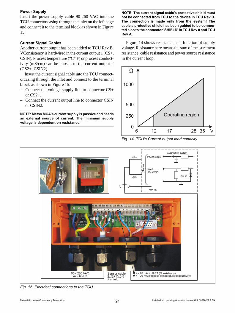
Power SupplyInsert the power supply cable 90-260 VAC into theTCU connector casing through the inlet on the left edgeand connect it to the terminal block as shown in Figure15.
Current Signal CablesAnother current output has been added to TCU Rev B.VConsistency is hardwired in the current output 1 (CS+,CSIN). Process temperature (°C/°F) or process conduct-ivity (mS/cm) can be chosen to the current output 2(CS2+, CSIN2).
Insert the current signal cable into the TCU connect-orcasing through the inlet and connect to the terminalblock as shown in Figure 15:– Connect the voltage supply line to connector CS+
or CS2+.– Connect the current output line to connector CSIN
or CSIN2.
NOTE:MetsoMCA's current supply is passive and needsan external source of current. The minimum supplyvoltage is dependent on resistance.
NOTE: The current signal cable's protective shield mustnot be connected from TCU to the device in TCU Rev B.The connection is made only from the system! Thecable's protective shield has been guided to be connec-ted also to the connector 'SHIELD' in TCURev 0 and TCURev A.
Figure 14 shows resistance as a function of supplyvoltage. Resistance here means the sum of measurementresistance, cable resistance and power source resistancein the current loop.
1000
500
250
06 12 35 V2817
Ω
Operating region
Fig. 14. TCU's Current output load capacity.
Fig. 15. Electrical connections to the TCU.
Installation, operating & service manual OUL00298 V2.2 EN21Metso Mircowave Consistency Transmitter

3.7. Metso MCA-F Sensor Deflector PlateInstallation GuideIf the flow contains pieces of string, lumps, etc., theMetso MCA must be protected with a special deflectorplate. Install the deflector plate at a distance of 170 mmbefore the sensor on a process unit welded in line withthe sensor. After you install the process unit, positionthe deflector plate such that its lag side is toward thesensor.
Select the process unit according to the sensor mater-ial and the diameter of the pipe (see Technical specific-ations). Select the deflector plate according to the ma-terial of the sensor material (see Technical specifica-tions).
Installing the process coupling:– Make a 71 mm hole in the flow pipe in line with the
sensor. The distance from the center of one hole tothe center of the other is 170 mm.
– If necessary, shape the process coupling (curvatureradius of installation surface) to the shape of thepipe.
– Place the process coupling in line with the hole andweld four adhesion welds around the seam.
– Weld a continuous weld around the seam.
Installing the deflector plate:– Check that the sealing ring is in the groove of the
flange.– Set the deflector plate into the process coupling such
that the plate curves toward the sensor.– Put the mounting clamps, screws and nuts into place
and tighten to a finger tightness.– Point the plate toward the sensor with e.g. a monkey
wrench.– Tighten the mounting clamp screws.
A
B
6.70"
170
a4
Align with the sensor
FLOW
Fig. 16. Metso MCA-F Sensor deflector plate installation guide, A. Saddle, B. Deflector plate.
Installation, operating & service manual OUL00298 V2.2 EN22Metso Mircowave Consistency Transmitter

4. Setting Up4.1. Mechanical Inspection1. Check that the delivery content corresponds to
what was ordered.2. Check that the device was not damaged in trans-
port.
4.2. InstallationInstall the sensor and TCU according to the instructionsin Chapter 3.
4.3. Cabling Inspection1. Check that the power supply is connected cor-
rectly.2. Check that the current output is connected cor-
rectly.3. Check that the sensor cable is connected correctly.
4.4. Electrical Inspection1. Connect the electronics to the power supply.2. Check that text appears on the TCU display.
Normally the main display appears, but in connec-tion with replacing a device you may be asked toselect calibration. In such a case, select calibrationof the unit (Sensor Electronics/TCU) that was notchanged.
3. Allow the device to warm up one hour beforestarting it up.
NOTE: If the TCU has been switched off for a long time,it may take a few minutes for text to appear on the dis-play. This is due to the charging of the device's internalback-up battery.
4.5. Configuration and Calibration1. Select the language and temperature unit (Celsius/
Fahrenheit) according to Chapter 6.3.2. Set the device date and time according to Chapter
6.5.3. Scale the current output according to Chapter 6.2.4. Calibrate the consistency according to Chapters
7.1 and 7.2.After you have completed these procedures, Metso
MCA is ready to measure consistency.
Installation, operating & service manual OUL00298 V2.2 EN23Metso Mircowave Consistency Transmitter

Notes
Installation, operating & service manual OUL00298 V2.2 EN24Metso Mircowave Consistency Transmitter
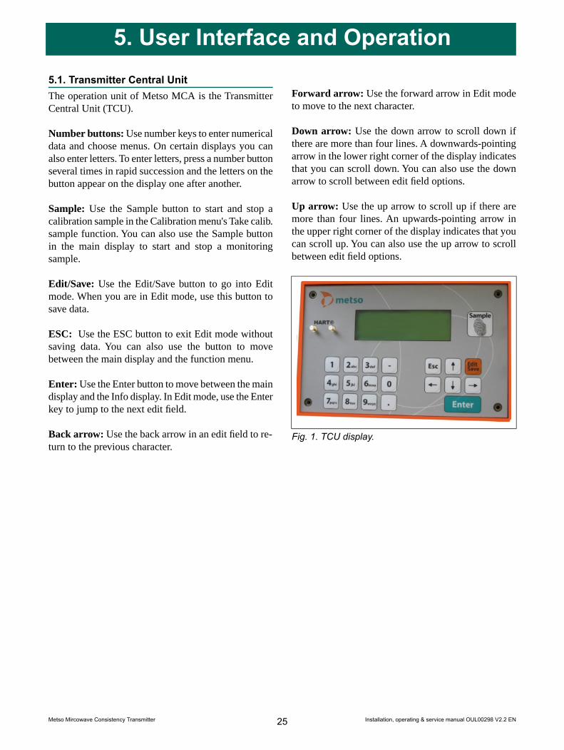
5. User Interface and Operation5.1. Transmitter Central UnitThe operation unit of Metso MCA is the TransmitterCentral Unit (TCU).
Number buttons: Use number keys to enter numericaldata and choose menus. On certain displays you canalso enter letters. To enter letters, press a number buttonseveral times in rapid succession and the letters on thebutton appear on the display one after another.
Sample: Use the Sample button to start and stop acalibration sample in the Calibration menu's Take calib.sample function. You can also use the Sample buttonin the main display to start and stop a monitoringsample.
Edit/Save: Use the Edit/Save button to go into Editmode. When you are in Edit mode, use this button tosave data.
ESC: Use the ESC button to exit Edit mode withoutsaving data. You can also use the button to movebetween the main display and the function menu.
Enter: Use the Enter button to move between the maindisplay and the Info display. In Edit mode, use the Enterkey to jump to the next edit field.
Back arrow: Use the back arrow in an edit field to re-turn to the previous character.
Forward arrow: Use the forward arrow in Edit modeto move to the next character.
Down arrow: Use the down arrow to scroll down ifthere are more than four lines. A downwards-pointingarrow in the lower right corner of the display indicatesthat you can scroll down. You can also use the downarrow to scroll between edit field options.
Up arrow: Use the up arrow to scroll up if there aremore than four lines. An upwards-pointing arrow inthe upper right corner of the display indicates that youcan scroll up. You can also use the up arrow to scrollbetween edit field options.
Fig. 1. TCU display.
Installation, operating & service manual OUL00298 V2.2 EN25Metso Mircowave Consistency Transmitter

5.2. Operations MenuThe operations menu is divided into the functions Cal-ibration, Configuration, Diagnostics and SpecialFunctions and their respective submenus.
Use the ESC button to access the function menufrom the main display. In the menus, you can use thenumber of the desired function to continue.
Use the ESC button to return to the previous level. Ifthe menu in view on the display has more than fourlines, i.e. more than fits on the display at one time, anarrow appears in the upper or lower right corner of thedisplay to indicate that you can scroll up or down withthe up arrow or down arrow.
MCA FT200 POS-1234 1=C2=Tu
4=D
ENTER
3=Lab ValuesCs = 3.12%T = 56.7CSTATUS = OK
1=Calibration2=Configuration
4=Special functions3=Diagnostics
% Range = 53.00 %mA = 12.48 mACabin T = 52.3 CMeas Att = 45.6 dB
ESC
Sample takingEnter labOffset correctionFiller
1
Calib. historySample history
Output signal 1Output signal 2User settingsDevice info
2
Set clockAddress
Error logDiag.valuesDiag.alarms
3
Chemical compensationTemperature compensationSensitivity correction
4
Recipes
Fig. 2. Operations Menu
Installation, operating & service manual OUL00298 V2.2 EN26Metso Mircowave Consistency Transmitter

6. Configuration6.1. Configuration menuThe configuration menu has the following functions:
1 = Output signal 12 = Output signal 23 = User settings4 = Device info5 = Set clock6 = Address
6.2. Choosing and scaling the output signalPress ESC button in the main display to move to Oper-ations menu. Select 1 to configure consistency currentoutput and you see the following display:
Lo (4mA) = 0.0 %CsHi (20mA) =10.0 %CsDamping =1 sFault sig =3.75 mA
Press the Edit button and enter values for the lowand high consistency values. If you wish, you may alsochange the filtering time and behavior of the electricitysource if self-diagnostics notes a fault state. Optionsfor this include 3.75 mA, 22.5 mA and freezing.
Process temperature or process conductivity can beconfigured in the current output 2. Select 2 and you seethe following display:
Selected variable:Process tempLo (4 mA) = 0.00Hi (20 mA) = 100.00Damping = 1 sFault sig = 3.75 mA
Press EDIT/SAVE. Use the up arrow and down ar-row buttons to make your selection and enter low andhigh values for the variable. Press EDIT/SAVE to savethe selection.
6.3. User SettingsIn the main display, push the ESC button to move toOperations menu. In the Operations menu, select Con-figuration/User settings. The following menu appears:
Trend Int :10 MINPosition :POS-1234Language :ENGLISHTemp unit :GEG CPassword :NAct sigLev :ON
The display fits four rows at a time. Use the up arrowand down arrow buttons to scroll through all the lines.Press the EDIT button to perform the following:
Trend Int: The trend table sampling interval. Use theup arrow and down arrow buttons to change it.
Position: Sensor's mounting position. In this field youcan use letters of the alphabet. To enter letters, press anumber button several times in rapid succession andthe letters on the button appear on the display one afteranother.
Language: Language selection. Use the up arrow anddown arrow buttons to select the language.
Temp unit: Temperature unit °C/°F Use the up arrowand down arrow buttons to select the temperature unit.
Password: Password Yes/No. Use the up arrow anddown arrow buttons to make your selection. If you se-lect Yes, the program asks for a password when youmove into Edit mode or if you intend to take a calibra-tion sample. The password is 3121. As a default, pass-word is not in use.
Act sigLev: Active signal level adjustment ON/OFF.Use the up arrow and down arrow buttons to make yourselection. If you Select ON, program make measure-ment signal level adjustment automatically when itgoes too low.
Installation, operating & service manual OUL00298 V2.2 EN27Metso Mircowave Consistency Transmitter

6.4. Device informationIn the Configuration menu, select Device Info (3). Thefollowing menu appears:
1 = Sensor Electronics2 = TCU
Select Sensor Electronics (1) to view sensor electron-ics information.
Type :S/N :123456HW Ver: 0001SW Ver: 0001
S/N: Sensor electronics serial number.
HW Ver: Sensor electronics version number.
SW Ver: Sensor electronics software version number.
Select TCU (2) to view corresponding data for theTCU.
6.5. Setting the date and timeIn the Configuration menu, select Set clock. The fol-lowing menu appears:
DateTime 12:14:53Enter to accept
10.12.10
The date and time shown in this menu are used as atime stamp in the trend table and for calibrationsamples. The main display status line shows "Set clock"until you have set the time. Use the EDIT and SAVEbuttons to edit and save date and time settings.
6.6. AddressMetso MCA's address on HART bus.
Installation, operating & service manual OUL00298 V2.2 EN28Metso Mircowave Consistency Transmitter

7. CalibrationThe Metso MCA is delivered with factory calibration,which means that it will measure consistency as soonas you switch the power on. Factory calibration is per-formed on the device in connection with final testingusing clean water.
We recommend that you calibrate the device againwhen setting it up. This allows the device settings tobe optimized for the conditions in which it will be used.Perform calibration by taking a consistency sample andentering its laboratory value into Metso MCA. Whenyou have performed this according to the instructionsin the next chapters, the status line on the display willchange from Factory Calibration to OK.
Calibration menu contains the following functions:
1 = Sample taking2 = Enter lab3 = Offset correction4 = Filler5 = Calib.history6 = Sample history
7.1. Sample TakingIn the main display, press the ESC button to move tothe Operations menu. Select Calibration/Sample taking.
Whenever a factory-calibrated device takes a sample,it adjusts the measurement signal to the optimal levelbefore taking the sample. This may cause a smallsteplike change in the device's consistency measure-ment. For this reason, the device may not be kept onconsistency control in this phase.
In addition, whenever a device that has been calib-rated takes a sample, it checks whether the measure-ment signal level is within an acceptable area. If thesignal level is outside the acceptable area, the devicesuggests that the signal level be adjusted. The signallevel adjustment may cause a small step-like changein the consistency measurement. Therefore you mustput consistency control on manual control if you allowthe device to adjust the signal level. A change inchemical concentration may cause a need to adjust thesignal level.
The sample-taking display is as follows:
Press sample-keystart sampling.Cs = 3.26 %Status:WAITING
to
Press the Sample button on the right side of the dis-play. The device begins averaging the measurementresult and a message "Sampling" appears on the Statusline. Go take a calibration sample, and then press theSample button again. The device finishes averagingthe measurement result and displays the result.
Sampling ready.Average Cs= 3.26 %Min= 3.20 Max= 3.33T = 56.3 C
In addition to showing the consistency average, thedevice also shows the sampling period's minimum andmaximum values as well as the process temperature.The minimum and maximum values indicate consist-ency fluctuation during the sampling period. Thisfluctuation should be small so that the consistencysample is reliable. The sample you take goes to theEnter Lab menu to await the laboratory value.
Press the ESC button to move back in the menus.
NOTE: If you press the Sample button when you are ina menu other than Take calib. sample, the device beginsaveraging themeasurement results. A sample taken thisway can not be used to calibrate the device. Rather, it isintended to be used to read the measurement result av-erage over the desired period of time for monitoringpurposes, for example.
Installation, operating & service manual OUL00298 V2.2 EN29Metso Mircowave Consistency Transmitter

7.2. Entering Laboratory ResultsWhen you have determined the sample's laboratoryconsistency, press the ESC button to move from themain menu to the Operations menu. Select Calibration/ Enter Lab, after which the following menu appears:
dd.mm.yy hh:mmMCA =00.00 %CsLab =00.00 %CsFiller = 0.00 %Cs
The first row shows the sample's date and time inthe following format: dd.mm.yy, hh:mm. The secondrow shows the consistency measured by Metso MCA.Press the Edit button to make the cursor appear in theLab field. In the Lab field, enter the calibration sample'slaboratory consistency. If the pulp contains fillers, enterin the fourth row in the Filler field the filler amount,which shows the proportional amount of filler as apercentage of the overall consistency. If the pulp doesnot contain filler, press the Save button to save yourchanges.
If you enter a value larger than zero in the Fillerfield, use the down arrow to move to the followinglines. Enter the proportional amount of each fillercomponent. If the filler consists, for example, entirelyof kaolin, enter 100% as the value of kaolin.
Press the Save button to save your changes.
NOTE: The lines Chem,MCA con and Lab con are neededonly for the chemicals compensation (chapter 9.1).
NOTE: The value for total filler sensitivity need only beentered with a 5 percentage point accuracy. The fillercomponents can also be entered based on an estimate.
NOTE: The sum of the proportions must equal 100%.
After you press Save, the device calculates the fillersensitivity value in the Filler sens field in the bottomline. This is the factor by which the device adjusts thedefault sensitivity set for the wood fiber.
The laboratory value for the sample can be enteredonly once in the Enter Lab menu. If necessary, you canperform offset correction for the consistency calibrationor change filler content as explained in the nextchapters.
7.3. Offset CorrectionIf laboratory monitoring indicates that the Metso MCAmeasurement results are consistently overly high orlow, you can correct this by performing offset correc-tion on the calibration. To do so, press the ESC to movefrom the main display to the Operations menu. SelectCalibration/ Offset correction, after which you see thefollowing display:
Offset = 0.00 %Cum. offset = 0.00 %
Press the Edit button to make the cursor appear inthe Offset field. Enter the desired offset correctionvalue. If, for example, Metso MCA shows a value thataccording to laboratory monitoring is 0.1% too high,enter an offset correction value of -0.1%. Press Savebutton to save your changes.
7.4. FillersIn this menu you can enter Filler sensitivity changes,if the filler sensitivity of the measured mass changesconsiderably (>10%). Press the down arrow to scrolldown the display one row at a time.
Filler = 20.0 %Kaolin = 100.0 %CaCO3 = 00.0 %Talc = 00.0 %TiO2 = 00.0 %Filler sens.=0.97
Enter a new value for Filler amount in the Filler fieldand new values for the filler components in the respect-ive fields. In the bottom row in the Filler sens field, theprogram calculates the change in sensitivity caused byfiller components in proportion to the wood fibersensitivity (wood fiber sensitivity = 1).
Installation, operating & service manual OUL00298 V2.2 EN30Metso Mircowave Consistency Transmitter
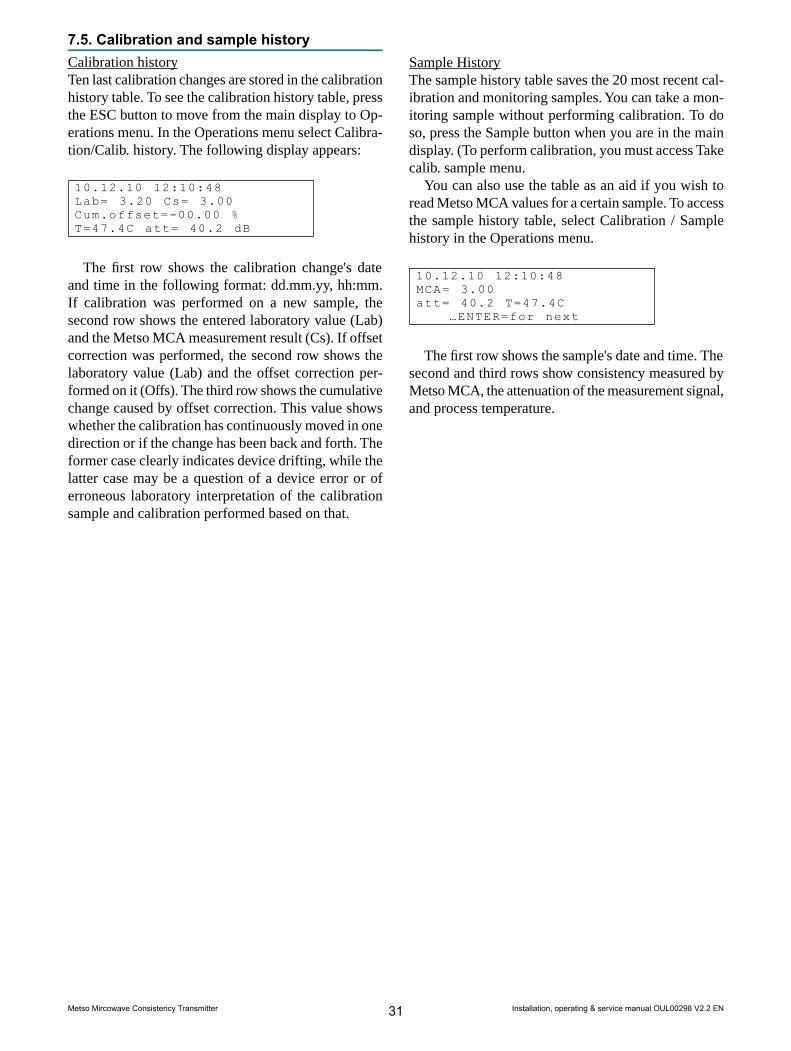
7.5. Calibration and sample historyCalibration historyTen last calibration changes are stored in the calibrationhistory table. To see the calibration history table, pressthe ESC button to move from the main display to Op-erations menu. In the Operations menu select Calibra-tion/Calib. history. The following display appears:
10.12.10 12:10:48Lab= 3.20 Cs= 3.00Cum.offset=-00.00 %T=47.4C att= 40.2 dB
The first row shows the calibration change's dateand time in the following format: dd.mm.yy, hh:mm.If calibration was performed on a new sample, thesecond row shows the entered laboratory value (Lab)and the Metso MCA measurement result (Cs). If offsetcorrection was performed, the second row shows thelaboratory value (Lab) and the offset correction per-formed on it (Offs). The third row shows the cumulativechange caused by offset correction. This value showswhether the calibration has continuously moved in onedirection or if the change has been back and forth. Theformer case clearly indicates device drifting, while thelatter case may be a question of a device error or oferroneous laboratory interpretation of the calibrationsample and calibration performed based on that.
Sample HistoryThe sample history table saves the 20 most recent cal-ibration and monitoring samples. You can take a mon-itoring sample without performing calibration. To doso, press the Sample button when you are in the maindisplay. (To perform calibration, you must access Takecalib. sample menu.
You can also use the table as an aid if you wish toread Metso MCA values for a certain sample. To accessthe sample history table, select Calibration / Samplehistory in the Operations menu.
10.12.10 12:10:48MCA= 3.00att= 40.2 T=47.4C
…ENTER=for next
The first row shows the sample's date and time. Thesecond and third rows show consistency measured byMetso MCA, the attenuation of the measurement signal,and process temperature.
Installation, operating & service manual OUL00298 V2.2 EN31Metso Mircowave Consistency Transmitter

Notes
Installation, operating & service manual OUL00298 V2.2 EN32Metso Mircowave Consistency Transmitter

8. Diagnostics8.1. Error TableIn the Diagnostics menu, select Error table (1). If self-diagnostics has not detected any errors, the displayshows "NO ERRORS". If self-diagnostics has detectederrors, the first line of the display shos the timestampwhen the error state began. The second row shows thetimestamp when the error state ended. The third rowshows the error type.
If the error state is still in effect, the endingtimestamp is shown as '--'. The message 'Shutdown' inthe place of the error state end time notifies, that theerror state was on when the power was shut down. Ifthe error state is still on when the power is switced onnext time, the error is reported as a new error. The Errortable shows the 10 most recent errors.
10.12.10 15:32:45--.--.-- --.--.--RLEV ALARM...ENTER=for next
8.2. Diagnostics ValuesIn the Diagnostics menu, select Diag. Values (2). Thefollowing display appears:
Cab temp = 40.6 C
Mlev = 121 mVRlev = 214.4 mVMstab = 9.8Rstab = 2.1El drift = -2.4VCO drift = 3.2
Proc temp = 42.0 C
The display shows values for the following diag-nostics measurements:
Cab temp: Sensor electronics temperature.
Proc temp: Process temperature.
Mlev: Measurement signal level.
Rlev: Reference channel signal level.
Mstab: Measurement channel signal stability.
Rstab: Reference channel signal stability.
El drift: Reference channel drift.
VCO drift: Signal generator drift.
Usage of this data for maintenance purposes is ex-plained in more detail in Chapter 10, "Troubleshootingand Maintenance".
8.3. Diagnostics LimitsIn the Diagnostics menu, select Diag. Limits (3). Thefollowing display appears:
Ctmp max = 90 /OFFPtmp max = 1000 /ONPtmp min = 0.0 /ONM.Lev min = 10.0 /ONR.Lev min = 100.0/ONMstab max = 20.0 /ONRstab max = 2.0 /ONEldr abs = 80.0 /ONVCOdr abs = 50.0 /ON
The display shows the error limit for each diagnosticsmeasurement as well as its effect on the current signal(ON/OFF). If necessary, you can change these as fol-lows: press the EDIT button and then enter a new errorlimit, or use the up arrow and down arrow buttons tochange the ON/OFF setting.
Even if the effect of the limit on the current signalis blocked by an OFF setting, an error message stillappears on the main display status line and error datais entered into the error table.
Installation, operating & service manual OUL00298 V2.2 EN33Metso Mircowave Consistency Transmitter

Notes
Installation, operating & service manual OUL00298 V2.2 EN34Metso Mircowave Consistency Transmitter

9. Special FunctionsThe Special Functions menu contains the followingfunctions:
1 = Chemical comp2 = Temperature comp3 = Sensitivity corr4 = Recipes
9.1. Chemical compensationLarge fluctuations in chemical content may cause errorsin Metso MCA consistency measurements. These errorscan be compensated for with chemical compensationbased on microwave damping measurement.
You can use chemical compensation as described inthe following two sections.
Entering Laboratory Values1. Take a sample as described in section 7.1.2. Determine the sample’s consistency and its filtrate
conductivity at room temperature.3. Go to the menu Enter Lab.4. Press the Edit button, and enter the laboratory
consistency and filler information. Press the Enterbutton to scroll the display down after the last line.
5. Select the chemical type with the up and downarrow buttons. Enter the sample’s conductivity inunits mS/cm.
Sample 12.08-04MCA = 3.00 CsLab = 0.00Filler = 0 %Kaolin = 0 %CaCO3 = 0 %Talc = 0 %TiO2 = 0 %Chem = NaOHMCA con = 2.40 mS/cmLab con = 0.00 mS/cmFiller sens=1.00
%%Cs
If the conductivity meter shows results in unitsmS/m, divide the result by 100, e.g. 550 mS/m = 5.5mS/cm.
If the conductivity meter shows results in unitsµS/cm, divide the result by 1000, e.g. 5500 µS/cm =5.5 mS/cm.
If the conductivity meter shows results in unitsµmho/ in, divide the result by 2500, e.g. 25 000 µmho/in = 10 mS/ cm.
Using Chemical CompensationAfter you enter the laboratory values, go to SpecialFunctions menu and select 1 (Chemical Compensation).The following display appears:
Chem.comp = OFFComp. value = 0.00 %MCA con = 0.00 mS/cmChem = NaOHLab cond = 3.4 mS/cm
Press the Edit button to make the cursor appear inthe Chemical Compensation field. The OFF text indic-ates that chemical compensation is not in use. Use theup and down arrows to change the text from OFF toON. Press Save, after which MCA begins using chem-ical compensation.
The second line Comp. Value shows the chemicalcompensation value, or the value that chemical com-pensation subtracts from the measurement result. Thethird and fourth lines show the chemical and laboratoryconductivity values entered by the user.
Installation, operating & service manual OUL00298 V2.2 EN35Metso Mircowave Consistency Transmitter

Temperature compensation correction curveMetso MCA compensates for the effect of temperatureon the measurement based on Pt-100 sensor measure-ment results. If, however, temperature dependency stillexists in the measurement result, it can be eliminatedby using the temperature compensation correctionfunction. The temperature dependency must first bedetermined via laboratory monitoring. To ensure thatthe temperature dependency is accurately defined, thetemperature area must be sufficiently broad.
The results of the laboratory monitoring are shownon an MCA Laboratory vs. Temperature graph. MCA- Lab graph points that are horizontal indicate that thereis no temperature dependency in the measurement res-ults. If the graph points are in a horizontal position ata level other than zero, you must perform offset correc-tion on the calibration as explained in chapter 7.3.
MCA - Lab graph points that are in a position otherthan the horizontal indicate that there is temperaturedependency in the measurement (figure 1). Temperaturedependency is eliminated by entering into MCA thetemperature compensation correction curve. To go tothe Temperature Compensation menu, Select SpecialFunctions/Temperature Comp. The following displayappears:
Temp. MCA-Lab1. 42.0 0.002. 48.1 0.103. 00.0 0.004. 00.0 0.005. 00.0 0.006. 00.0 0.00
Press the Edit button. Then enter the correction curveas pairs of points. Metso MCA then performs the cor-rection based on lines drawn through these points. Youcan enter up to six pairs of points. In the example inFigure 1, two pairs of points are sufficient. The pairsof points can be selected based on the results as in thefollowing example:
Temp MCA-Lab1. 42.0 C 0.00 %2. 48.1 C 0.10 %3. 00.0 C 0.00 %4. 00.0 C 0.00 %5. 00.0 C 0.00 %6. 00.0 C 0.00 %
Compensation is also successful outside the definedinterval such that the compensation curve is continuedbeyond the outermost points using the same slope.
MCA-Lab vs Temp
-0,2-0,15-0,1-0,05
00,050,10,150,2
41 42 43 44 45 46 47 48 49 50
Temp (°C)
MCA-Lab(%
)
Fig. 1. Determination of temperature dependence.
Installation, operating & service manual OUL00298 V2.2 EN36Metso Mircowave Consistency Transmitter

The effect of a new consistency calibrationIf a new consistency calibration is performed on MetsoMCA by taking a new sample after temperature consist-ency correction is determined, the measurement pro-gram performs a level adjustment on the compensationcurve.
In the level adjustment the program sets the valueof the compensation curve to zero in the calibrationtemperature, i.e. the effect of the compensation curveis zero at the calibration temperature. If for exampleyou performed a new consistency calibration with asample that has a temperature of 45 °C, the programwould perform a level adjustement of -0.05% on thecompensation curve and the compensation curve wouldappear as follows.
1. 42.0 -0.052. 48.1 0.05
Temp. MCA-Lab
Changing the correctionIf after the correction there is still some amount oftemperature dependency evident, you can most easilyperform the correction by editing the existing points.In this case the size of the desired correction iss addedto existing correction values.
If, for example, after the temperature compensationperformed above and the new consistency calibrationthe results appeared as shown in Figure 2. The correc-tion value for 42°C would be increased by 0.03% andthe correction value for 48.1°C would be decreased by0.02 %, after which the correction would appear asfollows:
Temp MCA-Lab1. 42.0 C -0.02 %2. 48.1 C 0.03 %
MCA-Lab vs Temp
-0,2-0,15-0,1-0,05
00,050,10,150,2
41 42 43 44 45 46 47 48 49 50Temp (°C)
MCA-Lab
(%)
Fig. 2. Results of new consistency calibration.
Installation, operating & service manual OUL00298 V2.2 EN37Metso Mircowave Consistency Transmitter
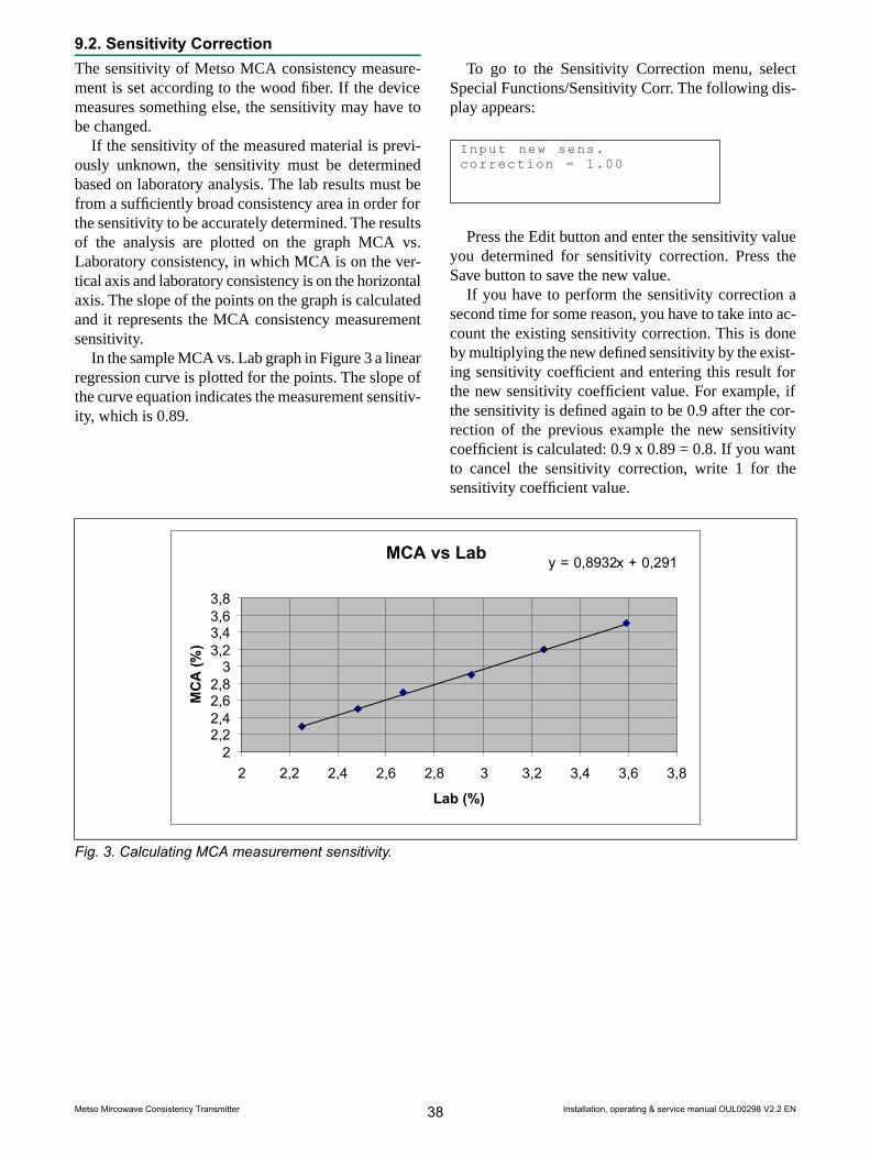
9.2. Sensitivity CorrectionThe sensitivity of Metso MCA consistency measure-ment is set according to the wood fiber. If the devicemeasures something else, the sensitivity may have tobe changed.
If the sensitivity of the measured material is previ-ously unknown, the sensitivity must be determinedbased on laboratory analysis. The lab results must befrom a sufficiently broad consistency area in order forthe sensitivity to be accurately determined. The resultsof the analysis are plotted on the graph MCA vs.Laboratory consistency, in which MCA is on the ver-tical axis and laboratory consistency is on the horizontalaxis. The slope of the points on the graph is calculatedand it represents the MCA consistency measurementsensitivity.
In the sample MCA vs. Lab graph in Figure 3 a linearregression curve is plotted for the points. The slope ofthe curve equation indicates the measurement sensitiv-ity, which is 0.89.
To go to the Sensitivity Correction menu, selectSpecial Functions/Sensitivity Corr. The following dis-play appears:
Input new sens.correction = 1.00
Press the Edit button and enter the sensitivity valueyou determined for sensitivity correction. Press theSave button to save the new value.
If you have to perform the sensitivity correction asecond time for some reason, you have to take into ac-count the existing sensitivity correction. This is doneby multiplying the new defined sensitivity by the exist-ing sensitivity coefficient and entering this result forthe new sensitivity coefficient value. For example, ifthe sensitivity is defined again to be 0.9 after the cor-rection of the previous example the new sensitivitycoefficient is calculated: 0.9 x 0.89 = 0.8. If you wantto cancel the sensitivity correction, write 1 for thesensitivity coefficient value.
MCA vs Lab y = 0,8932x + 0,291
22,22,42,62,83
3,23,43,63,8
2 2,2 2,4 2,6 2,8 3 3,2 3,4 3,6 3,8
Lab (%)
MCA
(%)
Fig. 3. Calculating MCA measurement sensitivity.
Installation, operating & service manual OUL00298 V2.2 EN38Metso Mircowave Consistency Transmitter

9.3. RecipesThe Recipe function may be necessary in specialfunctions in which measurement conditions change somuch that one calibration cannot cover it. Such achange may be e.g.– A change in consistency greater than the device
measurement range (±9 - ±15% depending on thetype of sensor),
– A change in the measured material, since differentmaterials have different consistency sensitivity or
– A large chemical fluctuation (e.g. change of chem-ical type) that cannot be compensated for withchemical compensation.In these cases, each process condition has its own
calibration and configuration performed. This calibra-tion and configuration is saved as its own recipe. Inaddition to consistency calibration, for each recipe youcan set chemical compensation, temperature consist-ency correction, sensitivity correction, and currentoutput scaling.
You can save a maximum of four recipes. If a recipeis in use, MCA indicates this by showing the name ofthe recipe on the main display status line instead of theOK text that is normally shown.
In Special Functions menu, select 4 (Recipes). Thefollowing display appears:
1=Choose recipe2=Clear recipe
Using RecipesYou can select a recipe either manually using thekeypad or with a binary control lines attached to theTCU. In Recipes menu, select 1 (Select recipe). Thefollowing display appears:
Select rec: OFF1.--------0000002.--------0000003.--------0000004.--------000000
Press the Edit button to make the cursor appear in theSelect field in the first row. Use the up and down ar-rows to select the desired recipe number (1-4) or the‘Binary’ selection method. If you select ‘Binary’, thenthe recipe is determined by the TCU binary inputs Bin0and Bin1 (refer to section 9.4 subsection Selecting theRecipe with Binary Inputs).
You may name the recipe if you wish as follows.Move the cursor to the desired recipe and write thename. Successive pressing on the number keys scrollsthrough the letters marked on the key. If you do notname the recipe, then the program gives it a defaultname (RES01, etc.).
Press Save to save the recipe selection and recipename. The date (ddmmyy) after the recipe name indic-ates the most recent calibration change. The text ‘ON’after the date indicates that the recipe in question is inuse.
Select rec: 11.REC01---150405 ON2.--------0000003.--------0000004.--------000000
When process conditions change such that you needa new recipe, select the new recipe either manually orbased on binary input according to the instructionsabove.
Select: BIN1.REC01---150405 ON2.REC02---2204053.--------0000004.--------000000
The program saves the recipe calibration as for theprevious recipe. The date 000000 indicates that the newrecipe is not calibrated with its own sample. Performcalibration with a new sample according to the instruc-tions in section 7. After calibration, the date 000000changes to the calibration date.
If necessary, scale the current output according tothe instructions in section 6.2 and configure the specialfunctions according to the instructions in chapter 9.Configure recipes 3 and 4 in the same way.
Installation, operating & service manual OUL00298 V2.2 EN39Metso Mircowave Consistency Transmitter

Clearing the RecipeIf you wish to empty the recipe, go to Recipe menu andpress 2 (Clear Recipe). The following display appears.
Clear recipe: 1
Press the Edit button and use the up and down arrowbuttons to select the desired recipe. Press the Savebutton, after which the program asks you to confirmyour selection.
This action willclear recipe 1ENTER=ClearESC=Cancel
Press Enter to clear the recipe.
Note: You cannot empty the recipe that is currently inuse.
Selecting the Recipe with Binary InputsThe recipe can be selected using two digital controllines connected to the TCU connector casing. In thiscase, you can use up to four recipes. If only one binaryinput is in use, you can use two recipes.
Select ‘Binary’ as the recipe selection method accord-ing to the instructions in section Using Recipes.
Select: BIN1.REC01---150405 ON2.REC02---2204053.--------0000004.--------000000
Connect e.g. the automation system’s digital controllines to the connector casing binary inputs BIN0 andBIN1. Connect the grounded line to BINGND. Selectthe recipe with the digital control lines according tothe following table. The text ‘ON’ next to the recipenumber indicates which recipe is selected.
BIN0 BIN1 Recipe0 0 11 0 20 1 31 1 4
Installation, operating & service manual OUL00298 V2.2 EN40Metso Mircowave Consistency Transmitter

10. Troubleshooting
NOTE: Before disconnecting the sensor or the flow-through antenna, check that the process pipe is emptyand unpressurized and that disconnection is safe.
Metso MCA does not require scheduled maintenance.The instructions in this chapter refer to fault conditions.
10.1. TroubleshootingMetso MCA's self-diagnostics monitors certain internalmeasurements and generates error messages if themeasurements exceed alarm limits. Self-diagnosticsalso detects definite faults, which are often caused bysensor electronics.
An erroneous measurement result may also be dueto antenna leakage, contamination, a fault in the antennacable, or a process variable that is skewing the meas-urement. Self-diagnostics may not detect such a fault.
The fault may also be in the current output sent bythe TCU. In this case, the measurement is correct, butthe current output sent to the automation system is in-correct.
The following figure 1 contains a troubleshootingchart for faults that appear in different ways.
10.2. Process Conditions• AirAir in the pulp is seen in measurements as an excessin consistency. Air exists as bubbles of different sizes.Small bubbles dissolve in water at pressure of approx-imately 1.5 bar, but large bubbles may disturb processeseven at pressures higher than that. At most, the errorcaused by air may be in the range of several percentagepoints (percentage of consistency). Air causes disturb-ances to the process itself, so the formation of airbubbles should be avoided.
Air formation mechanisms– Air is mixed with pulp, for example, when it is
dropped into the stock tank. If the level in the stocktank is low, if the point of impact in near the pump,or if the flow-through time in the tank is low, thenair is not able to escape properly from the pulp be-fore the pulp is forced into a departing flow. Thebest way to put pulp in the tank is to run the inputpipe under the level of pulp in the tank.
– In addition, a strong stirring at a low surface levelcan cause a whirl that causes air to be mixed intothe pulp.
– Air may also become mixed into the pulp througha leaking joint on the pump's intake side.
– The dilution water may also contain air and causeair bubbles in the pulp.
– Air can build up in bends in dilution or pulp pipesif the bends are at the highest spot in the productionline. In such cases, an air pocket is formed andcontinues to grow in a bend in a pipe. When the airpocket is large enough, it begins moving with theflow in the pipe. An air mass such as this may causea momentary error in consistency measurements.
– Air may be generated in the pulp through foamingcaused by chemicals as well.
Metso MCA
SLOW DRIFT/ERROR INDICATION
Contaminationof antennas
Antennaleakage
Check processconditions
Check self-diagnostic’serror messages
Sensorelectronics failure
Broken fork probe
A SUDDEN CHANGE INLEVEL WHEN PROCESSCONDITIONS ARE STABLE
REFERENCECHANNEL FAILURE
Pieces of string,etc., around theFork Sensor body
Sensorelectronics failure
Sensorelectronics failure
Fig. 1. Troubleshooting chart.
Installation, operating & service manual OUL00298 V2.2 EN41Metso Mircowave Consistency Transmitter

• ChemicalsChemicals in the pulp weaken the measurement signal.Therefore, a maximum conductivity limit has beendefined for each sensor type. If conductivity exceedsthis limit, the measurement signal becomes too smalland the measurement result contains noise and errors.A large overshoot in conductivity can cause the meas-urement signal to disappear altogether. Fluctuatationsin the chemical concentration may also cause smallerrors within the conductivity specification limits.
You can eliminate these errors by using MCAchemical compensation (See Chapter 9 Special Func-tions).
• TemperatureTemperature affects consistency measurement, whichMCA compensates for with its own temperaturemeasurement. If the measurement is nonetheless notedto be temperature-dependent, it can be eliminted withthe help of temperature compensation (See Chapter 9Special Functions).
• Antenna LeakageAntenna Leakage causes a measurement error, whichappears as a slow upward or downward drift. In caseof leakage, you must change the antenna and the an-tenna cable as well because the cable may also havegotten wet.
In FT sensor models, a clear case of leakage can bedetected by removing the antenna cover and checkingwhether water drips from between the antenna and theconnector that is connected to it.
In the Fork Sensor, a clear case of leakage can bedetected by removing the sensor electronics andchecking whether water has accumulated in the connect-ing pipe.
• Antenna ContaminationAntenna Contamination causes an upward drift in themeasurement. If the antenna is cleaned periodically,e.g. as a result of being washed or changing the woodspecies, then the error disappears. The antenna is madeof polished ceramic, so contamination may be causedby some material that is adhering to this surface.Checking for antenna contamination requires a breakin the process and removal of the device.
• Pieces of string, etc. wrapped around Fork Sensorbody
The Fork Sensor is inserted into the pipe, and thereforeit is not recommended to install it in a position in whichthe pulp may contain strings or other such materials,which could become wrapped around the Fork Sensor.If these materials do become wrapped around the sensorbody, the measurement drifts upwards. The speed ofthe drift is directly dependent on how rapidly thesematerials build up around the sensor and it can evenby very rapid.
Checking the Fork Sensor requires it to be removedfrom its process coupling.
• Broken Fork probeThe Fork Sensor is inserted into the pipe, and thereforeit is not recommended to install in in a position in whichthe pulp may contain stones or other such materials,which can damage the ceramic antenna shield at theend of the sensor body. In order to become broken,ceramic requires a powerful blow. In such cases, thefault appears as a rapid level change upwards ordownwards in the measurement, followed by drifting.
Checking for a broken fork probe requires that thesensor be removed from its process coupling.
• Sensor Electronics FailureA typical electronics failure appears as a rapid levelchange in the measurement and as a rapid reduction insignal level after some component breaks. A referencechannel failure indicates that the fault is in the sensorelectronics. Self-diagnostics includes an alarm limitfor the reference channel signal level, which detectsobvious cases of broken components.
If all the aforementioned possibilities can be elimin-ated, then small errors or drifting in the measurementmight be caused by sensor electronics. In such a case,all the self-diagnostics measurements might be withinallowed limits due to which self-diagnostics does notdetect the error.
To locate the error, it might help to analyze thedevice's internal trend and sample history table andcompare these to the error results if such error data isavailable (e.g. in laboratory monitoring). This requiresa deeper knowledge of the sensor and is typically per-formed by Metso maintenance personnel.
• Reference Channel FailureRefer to Sensor Electronics Failure.
Installation, operating & service manual OUL00298 V2.2 EN42Metso Mircowave Consistency Transmitter

10.3. Self-diagnostics error messagesSelf-diagnostics monitors the signal of the measurementchannel measuring the process and the signal of device'sinternal reference channel. Self-diagnostics is capableof detecting clear fault states, in which case it generatesan alarm by freezing the current signal or setting it to3.75 or 22.5 mA, according to user specifications.
If, however, the fault is not a clear device fault butrather measurement drifting, then self-diagnostics maynot necessarily be able to detect it. In such cases,comparing self-diagnostics measurements with devicedrifting and seeking correlations between these mayhelp in locating the source of the error.
Cab temp: Shows sensor electronics temperature. Acontinuously high temperature reduces the averagefault interval. If the electronics temperature is continu-ously over 75 degrees C, then it is recommended toinstall the Vortex cooler in the sensor base plate. Referto chapter 11.7 for more information.
Mlev: Shows the measurement signal level in milli-volts. A decrease in measurement signal level belowthe alarm level may be caused by an electronics failure,antenna leakage, or high conductivity of the measuredpulp. If it is an electronics failure, then the referencechannel signal level Rlev is usually decreased to belowalarm limits.
Rlev: Shows the device's internal reference channel'ssignal level in millivolts. A decrease in the signal levelto below alarm limits is always caused by a sensorelectronics failure.
Mstab: Mstab shows the stability of the measurementchannel signal. Stability reflects the effect of bothelectronics and the measured pulp. Assuming that theelectronics are in order (see Rstab), you can determinebased on the Mstab value whether or not the processcontains large air bubbles that are causing measurementerrors. Large air bubbles cause both a rise in the Mstabvalue as well as a temporary error in consistencymeasurement. The level of the Mstab value is also af-fected by consistency and sensor model. Fork Sensortypically has a slightly higher Mstab value than FTSensor. Also, Mstab value is higher at a higher consist-ency than at a lower consistency.
Rstab: Rstab shows the stability of the device's refer-ence channel signal. The smaller the value, the morestable the signal. An Rstab alarm is caused by sensorelectronic failure.
El drift: El drift value shows the drift in electronicdelay measured by the reference channel. This valueis compensated out of the measurement channel result,so electronic drift does not cause an error in the meas-urement result. An El drift alarm is caused by sensorelectronic failure.
VCO drift: VCO drift shows the drift in sensor elec-tronics signal generator. A VCO drift alarm is causedby sensor electronic failure.
Installation, operating & service manual OUL00298 V2.2 EN43Metso Mircowave Consistency Transmitter

Notes
Installation, operating & service manual OUL00298 V2.2 EN44Metso Mircowave Consistency Transmitter

11. Replacing Components11.1. Sensor ElectronicsRemoval (Fig. 1)1. Disconnect the electricity by separating the sensor
cable from the connector at the edge of the baseplate.
2. Remove the electronics protective cover.3. Disconnect the sensor cable and Pt-100 sensor
connectors from the electronics and bend them tothe side.
4. Loosen the three mounting screws and lift thesensor electronics evenly out of its position bypulling on the mounting screws.
NOTE: Sensor electronics is aligned into place by threeguide pins, which keep it in place even when themounting screws are loosened.
Installation:1. Align the groove in the edge of the electronics
with the connector on the edge of the base plate.Move the electronics and press gently until theguide pins on the base plate are aligned with theholes on the base of the electronics. Then pressthe electronic evenly onto the base plate.
2. Screw in the three sensor electronics mountingscrews.
3. Connect the sensor cable and Pt-100 sensor con-nectors to the electronics.
4. Place the sensor cover into position.5. Connect the sensor cable to its connector at the
edge of the base plate.6. If after the electricity is switched on MCA asks
you to choose calibration, choose as follows;- TCU: if you did not replace the TCU.- Default calibration: if you have replaced theTCU as well.
Fig. 1. Removal diagram for sensor electronics.
Installation, operating & service manual OUL00298 V2.2 EN45Metso Mircowave Consistency Transmitter

11.2. Antenna cables, Fork Sensor
NOTE: Before removing the sensor, check that the pro-cess pipe is unpressurized and empty and that it is safeto remove the sensor.
Removal: (Fig. 2 and 3)1. Place the body of the sensor into a table vice such
that the sensor head is on top. Use aluminumbuffers in the between the vice jaws and thesensor.
2. Remove the sensor electronics according tochapter 11.1.
3. Lift the Pt-100 cable from the tape on the baseplate.
4. Remove the uppermost mounting screw on theprobe antenna side. Screw in a longer screw in itsplace, e.g. M6x50 is a suitable size. This screwwill serve to hold the sensor in place when thebase plate is removed.
5. Remove the five other base plate mounting screws.6. Pull the base plate 10mm away from the sensor
body.7. Disconnect the antenna cable from the base plate
by holding the connector in place with an 8mmwrench (e.g. SMA wrench) while you use a 10mm socket key to open the lock bushing that isattached to a connector on the electronics side ofthe base plate.
NOTE: Don't allow the connector body to rotate whileyou turn the lock bushing.
8. Remove the long steering screw and the base platefrom the sensor body. At the same time, guide thePt- 100 cable through the base plate.
9. Remove the cable of the flush-mounted antennawith an SMA wrench.
10. Remove the cable support bushing by pulling itthrough the feed-through hole with drawing pliers.
11. Open the Pt-100 coupling on the outer edge of thesensor shaft with plug spanner OUL00323. Checkthat the cable also rotates during removal.
12. Pull the Pt-100 sensor about 100mm outwards andlet it hang by its cables.
13. Remove the MCX connector from the probe an-tenna by prying with pointed pliers. Push the Pt-100 cable to the side so that the connector is ableto be removed.
14. Pull the microwave cable carefully out throughthe feed-through hole on the shaft toward theflushmounted antenna.
Connecting:1. Install the probe antenna's microwave cable into
the MCX connector: Push the cable end with thestraight angle connector through the shaft suchthat the connector is just oppisite the probe an-tenna connector. Connect the connector to the endhole by prying with a 4mm screwdriver. Handlethe cable with care, so that it stays in shape andeases future installation.
2. Install the flush-mounted antenna's cable into theSMA connector: Put the connector that is to beinstalled in the base plate on the side of the sensorbody opposite the previous cable. Tighten theSMA connector with a torque wrench to 1 Nmtorque. Handle the cable with care, so that it staysin shape and eases future installation.
3. Install the thermoelement on the sensor body:Check that the O-ring is in the sealing groove.Remove the old teflon tape from the thread andput two new layers of teflon tape in its place.Check that the tape does not cover the O-ring.Take care that the cable also rotates . Tighten itwith plug spanner OUL00323 to 12 Nm torque.
4. Set the cable support bushing into place and puta drop of super glue on the side of the bushingbefore attaching it. The antenna cable should bein the upper groove, and the Pt-100 sensor cableshould be in the lower groove.
Installation, operating & service manual OUL00298 V2.2 EN46Metso Mircowave Consistency Transmitter
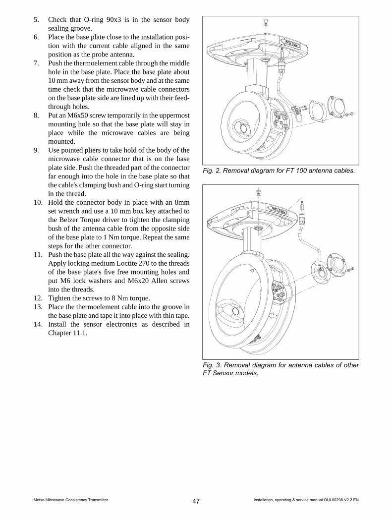
5. Check that O-ring 90x3 is in the sensor bodysealing groove.
6. Place the base plate close to the installation posi-tion with the current cable aligned in the sameposition as the probe antenna.
7. Push the thermoelement cable through the middlehole in the base plate. Place the base plate about10 mm away from the sensor body and at the sametime check that the microwave cable connectorson the base plate side are lined up with their feed-through holes.
8. Put an M6x50 screw temporarily in the uppermostmounting hole so that the base plate will stay inplace while the microwave cables are beingmounted.
9. Use pointed pliers to take hold of the body of themicrowave cable connector that is on the baseplate side. Push the threaded part of the connectorfar enough into the hole in the base plate so thatthe cable's clamping bush and O-ring start turningin the thread.
10. Hold the connector body in place with an 8mmset wrench and use a 10 mm box key attached tothe Belzer Torque driver to tighten the clampingbush of the antenna cable from the opposite sideof the base plate to 1 Nm torque. Repeat the samesteps for the other connector.
11. Push the base plate all the way against the sealing.Apply locking medium Loctite 270 to the threadsof the base plate's five free mounting holes andput M6 lock washers and M6x20 Allen screwsinto the threads.
12. Tighten the screws to 8 Nm torque.13. Place the thermoelement cable into the groove in
the base plate and tape it into place with thin tape.14. Install the sensor electronics as described in
Chapter 11.1.
Fig. 2. Removal diagram for FT 100 antenna cables.
Fig. 3. Removal diagram for antenna cables of otherFT Sensor models.
Installation, operating & service manual OUL00298 V2.2 EN47Metso Mircowave Consistency Transmitter

11.3. Antenna Cables, FT Sensor
NOTE: Before removing the sensor, check that the pro-cess pipe is unpressurized and empty and that it is safeto remove the sensor.
Removal1. Remove sensor electronics according to the instruc-
tions in section 11.1.2. Open the inlet bushing of the antenna cable con-
nected to the base plate. Slide it down until theconnector body at the end of the cable becomesvisible.
3. Hold the connector body in place with an 8 mmwrench (e.g. SMA wrench) while you use a 10mm box wrench to open the lock bushing that isattached to the connector on the other side of thebase plate.
NOTE: Don't allow the connector body to rotate whileyou turn the lock bushing.
4. Loosen the four mounting screws of the sensorcover and lift the cover off.
5. Loosen the antenna cable's SMA connector fromthe antenna end with an SMA wrench or SMAwrench adapter. In sensor model FT 100, you mustalso loosen two cable feed-through mountingscrews.
6. Lift the antenna cable out of its mounting grooveby, for example, prying the casing tube with ascrewdriver such that the cable begins to comeout of the groove starting with the antenna end.
7. When the cable's casing is separated from thesensor body, pull the cable connector on the baseplate carefully out of its hole.
NOTE: Lift the cable by its casing tube, not by the cableitself.
NOTE: Be careful not to dent the antenna cable connectoron the base plate.
Installation:1. Check that the nylon sealing ring is in place in the
base plate at the bottom of the antenna cablefeedthrough thread.
2. Place the antenna cable connector gently into thehole in the base plate and press the antenna cablecasing into its mounting groove. Check that theantenna end feed-through collar fits into place.
3. Take hold of the antenna cable connector on thebase plate with an 8 mm set wrench. From theother side of the base plate, screw on the antennacable lock bushing with a 10 mm box key attachedto the Beltzer Torque driver to 1 Nm torque. Donot use force in tightening the lock bushing; toomuch force will damage the connector.
4. Slide the antenna cable's through the inlet bushingdown to the base plate and screw it into place.
5. Screw the antenna cable connector on the antennainto the antenna connector with an SMA wrenchor or with the SMA Torque Wrench Adapter at-tached into a SMA wrench to the torque indicatedby the wrench. In sensor model FT-50/FT-100,you must also screw in two feed-through mountingscrews.
6. Attach the antenna's cover with its four mountingscrews.
Installation, operating & service manual OUL00298 V2.2 EN48Metso Mircowave Consistency Transmitter

11.4. Antennas, Fork Sensor
NOTE: Before removing the antennas, check that theprocess pipe is empty and unpressurized and that remov-al is safe.
Removal:1. Remove the sensor electronics as described in
Chapter 11.1.2. Remove the antenna cable of the antenna that is
being replaced as described in Chapter 11.2.
Flush-mounted antenna:3. Unscrew two M8 Allen screws to remove the an-
tenna from its mounting clamp.4. Pull the antenna out of the inlet hole and remove
the O-ring.5. Unscrew two M4 screws to remove the clamp
from the antenna.
Probe antenna:6. Use socket key OUL00325 and a 13mm ring
spanner to remove the probe antenna.
Installation:Flush-mounted antenna:1. Attach the mounting clamp to the antenna with
two M4x16 screws with washers.2. Clean the sealing surfaces of the antenna installa-
tion hole using e.g. isopropanol.3. Place a new O-ring into the installation hole
against the collar.4. Place the antenna into position. Attach it with
M8x20 Allen screws and washers using a 6mmAllen wrench. Use locking medium Loctite 270on the threads.
5. Tighten the antenna's mounting screws to 19 Nmtorque.
Probe antenna:1. Clean the sealing surface with e.g. isopropanal.2. Place a new O-ring into the sealing groove.3. Put locking medium Loctite 270 on the threads.4. Screw the probe antenna into the sensor body us-
ing socket key OUL00325 to 10 Nm torque.5. Install the antenna cable(s) as described in Chapter
11.2.6. Attach the sensor electronics as described in
Chapter 11.1.
11.5. Antennas, FT Sensor
NOTE: Before removing the antennas, check that theprocess pipe is empty and unpressurized and that remov-al is safe.
Removal:1. Remove the sensor electronics as described in
Chapter 11.1.2. Remove the antenna cable as described in 11.2.3. Remove the antenna's six mounting screws with
a 5mm Allen wrench. In the FT-100 model thereare four mounting screws and the washers are self-sealing.
4. Pull the antenna out of the inlet hole and removethe O-ring.
5. Remove the antenna from the flange by unscrew-ing two M4 screws.
Installation:1. Attach the antenna to the flange with two M4x12
screws with washers.2. Clean the sealing surfaces of the antenna installa-
tion hole using e.g. isopropanol.3. Place a new O-ring into the installation hole
against the collar.4. Put locking medium Loctite 270 onto the flange's
six mounting threads.5. Check that the antenna flange O-ring is in place
and then insert the antenna into place in the an-tenna coupling.
6. Tighten the antenna's six M6x16 mounting screwsand washers with a 5mm Allen wrench to 8 Nmtorque. In the FT-100 model there are four screwsand the washers are self-sealing.
7. Connect the sensor cable and the sensor electron-ics back in reverse order.
Installation, operating & service manual OUL00298 V2.2 EN49Metso Mircowave Consistency Transmitter

11.6. TCU
NOTE: Before removing the antennas, check that theprocess pipe is empty and unpressurized and that remov-al is safe.
Removal:1. Disconnect the network voltage form the TCU
and remove the network voltage lines from theTCU terminal block.
2. Remove the sensor cable and the factory's systemcable from the TCU terminal block.
3. Remove TCU from its shield.
Installation:1. Attach the new TCU to the shield.2. Connect the sensor cable, network voltage cable
and the factory's system cable to the TCU terminalblock.
3. Switch on the network voltage.
NOTE: It may take a few minutes for text to appear onthe display. This is due to the charging of the device'sinternal back-up battery.
4. If the program asks you to select calibration, select– Sensor electronics calibration if you did not replace
sensor electronics.– Default calibration if you replaced sensor electronics
as well.
Fig. 4. Installing Vortex Cooler.
11.7. Installing Vortex CoolerVortex Cooler is available as an option. Its code isOUL00285 (Fig. 4).
Vortex Xooler is used to cool the sensor electronicsunit. Cooling is necessary if the electronics internaltemperature (Cab Temp) rises above 75 C (167 F) dueto the effects of its surroundings. Perform installationas for FT and Fork sensors.
Vortex Cooler installation kit contains the followingparts:1. Cooler with 6 hose coupling.2. Screws M6x25, 2 pieces.3. Lock washers M6, 2 pieces.4. Thermal conductivity grease.
Installation:1. Apply thermal conductivity grease to the installa-
tion surface of the cooler's black casing.2. Set the cooler on the base plate such that the
mounting holes are in line with each other.3. Screw in the washers and screws and tighten them
with a 5mm Allen wrench.4. Insert the air hose with internal diameter of 6 mm
(1/ 4") into the hose nipple using a hose clamp.
During installation, note the following:The cooler is installed between elements. If lack ofavailable space so dictates, you can move the cooler toone end of the element by removing the plug and pla-cing the cooler into that thread. Then put the plug inthe central thread. The cooler's outlet pipe can pointupwards (recommended) or to the side, but not down-wards.
Cooling:The maximum volume flow in cooling is 230 nl/min.If you do not use a flow meter, start the air flow care-fully and then increase it slowly until the necessarycooling efficiency is reached.
NOTE: The outlet pipe releases hot air. Check that thereare no cables that touch the outlet pipe or in its near vi-cinity.
Installation, operating & service manual OUL00298 V2.2 EN50Metso Mircowave Consistency Transmitter

12. HART® User Interface12.1. About the interfaceHART® is a registered trademark of HART Commu-nication Foundation. HART communication is amethod of transferring information digitally betweenfield devices and host devices (e.g. HART Communic-ator).
In order to function properly HART requires TCUprogram version C or higher and a HART Communic-ator that contains the Metso MCA command base.
HART Communicator is connected in parallel to thecurrent output, e.g. to the connector pins on the frontpanel of the TCU.
You can perform the same operations on MetsoMCA HART user interface as on the device’s TCUuser interface. Figure 1 shows the HART Communic-ator operation menu.
When you connect HART Communicator to MetsoMCA, the following menu appears.
MCA: MCA-1234Online1 Measurement2 Configure3 Calibrate4 Diagnostics
Measurement
Configuration
Calibration
Diagnostics
Range ValuesUser SettingsDevice InfoSensor ElectronicsTCUSet time
Take sampleEnter LabOffset correctionFillersCalibration historySample HistorySpecial Functions
Chemicals Comp.Temperature Comp.SensitivityRecipes
PV %CsProcess TempMeas AttConductivityAO mA% of RangeActive Recipe Trend Int
PositionLanguageTemp Unit
Diag historyDiag valuesDiag alarmsDigital inputsLoop test
Lab CsFiller %Clay %CaCO3 %Talc %TiO2 %ChemicalLab cond
Low RangeHigh RangeDampingAlarm Current
Poll addrManufacturerModelFinal Asbly numberTagMessageUniversal revDescriptor
Filler %Clay %CaCO3 %Talc %TiO2 %
Fig. 1. HART Communicator operation menu.
Installation, operating & service manual OUL00298 V2.2 EN51Metso Mircowave Consistency Transmitter

12.2. MeasurementMeasurement menu shows the Metso MCA measure-ment results.
MCA: MCA-1234Measurement1 Sensor Type FT2002 Cs 0.00 %Cs3 Prc Temp 57.3 °C4 Status OK5 Conductivity 2.43 mS/cm6 % of range 36.72 %7 mA 9.88 mA8 meas Att 32.4 dBRecipe # OFF
Sensor Type:
Cs: Measured consistency.
Prc Temp: Process temperature.
Status: Device status (OK, Alarm, etc.).
Cab Temp: Sensor electronics temperature.
% of range: Consistency current output value as apercentage of the current output range.
mA: value of ... in milliampers.
meas Att: The measured microwave damping in theprocess.
Recipe #: The number of the recipe in use (refer toChapter 9.3).
12.3. ConfigureIn Configure menu you can configure Metso MCA'scurrent output and certain other parameters. Configuremenu also shows device information.
MCA: MCA-1234Configure1 Range Values2 User settings3 Device info4 SENSOR ELECTRONICS5 TCU6 Set Clock
Range valuesLowRnge: Consistency that correlates to current outputlower limit 4 mA.
UppRnge: Consistency that correlates to current outputupper limit 20 mA.
Damping: Damping time of the current output.
Alarm cur: How the output signal reacts to errorsituations detected by self-diagnostics. Options: 3.7mA / 22.5 mA / freeze.
User settingsTrend Int: The sampling interval of the devices´s in-ternal trend table.
Pos: Device position information.
Lang: TCU language version.
Temp unit: Process temperature unit °C / °F.
Installation, operating & service manual OUL00298 V2.2 EN52Metso Mircowave Consistency Transmitter

Device infoPoll Addr: The device´s HART address.
Manufacturer: Name of device manufacturer (Metso).
Model: Device name.
Final asmbly num: Field device identification num-ber.
Universal rev: The Universal Device Descriptionversion supported by the device.
Tag: Text entered by the user, the tag is shown at thetop of the display after the device name.
Message: Text entered by the user.
Descriptor: Text entered by the user.
Sensor ElectronicsSensor type: Sensor model.
Sensor S/N: Sensor electronics serial number.
Sensor HW rev: Sensor electronics revision.
Sensor SW rev: Sensor electronics software revision.
TCUS/N A: First part of TCU serial number.
S/N B: End part of TCU serial number.
HW rev: TCU revision.
SW rev: TCU software revision.
Cal date: TCU´s final testing date.
Cal ID: Tester´s initials.
Set ClockDate: The date in mm/dd/yy.
Hours:
Minutes:
Seconds:
12.4. CalibrateMetso MCA is calibrated with single-point calibration.Calibrate menu contains menu items for sample takingand entering the laboratory value.
In addition, you can perform a level correction onthe measurement, perform various special functionsand view calibration and sample history data:
MCA: MCA-1234Calibrate1 Sample taking2 Enter Lab3 Level corr4 Filler5 Lab cal History6 Sample history7 Special functions
Sample takingThis function allows you to take a sample for single-point calibration.
Move the cursor on to Sample taking and press theright arrow The following display appears:
Press OK to startsample taking
ABORT OK
Press F4 (OK). Metso MCA begins to average themeasurement result for the sample and the followingdisplay appears:
Press OK to stopsample taking
ABORT OK
Take the sample, and then press OK (F4) again.Metso MCA shows the results of its measurement:
MCA:MCA-1234Sampling readyAverage Cs = 3.02 %Min: 3.01 % Max: 3.03 %T = 42.3 °C
ABORT OK
Select OK (F4) to return to Calibrate display.
Installation, operating & service manual OUL00298 V2.2 EN53Metso Mircowave Consistency Transmitter

Enter LabThis function allows you to enter the laboratory valuefor the sample taken.
Move the cursor onto Enter Lab and press the rightarrow. The following display appears:
MCA: MCA-1234Enter labLab CsFiller%KaolinCaCO3TalcTiO2ChemicalLab Cond
Enter the necessary laboratory information:Lab Cs: Laboratory consistency.
Filler %: The relative proportion of filler in the totalconsistency, shown as a percentage.
Kaolin%: The relative proportion of Kaolin in thefiller, shown as a percentage.
CaCO3%: The relative proportion of CaCO3 in thefiller, shown as a percentage.
Talc%: The relative proportion of talc in the filler,shown as a percentage.
TiO2%: The relative proportion of TiO2 in the filler,shown as a percentage.
Chemical: Chemical type (required only for chemicalcompensation).
Lab cond: Laboratory conductivity mS/cm (requiredonly for chemical compensation).
NOTE: If the conductivity meter shows results in unitsµmho/in, divide the result by 2500, e.g. 25 000 µmho/in= 10 mS/cm. If the conductivity meter shows results inunits mS/m, divide the result by 100, e.g. 550 mS/m = 5.5mS/cm. If the conductivity meter shows results in unitsµS/cm, divide the result by 1000, e.g. 5500 µS/cm = 5.5mS/cm.
Offset corrThis function allows you to perform level correctionon the measurement.
Move the cursor onto Level corr and press the rightarrow. The following display appears:
MCA: MCA-1234Set the offsetcorrection: [-10,10]
00
DEL ABORT ENTER
Enter the desired value and press ENTER (F4). TheHART Communicator sends the value to Metso MCA.
FillerMetso MCA measures filler, but at a slightly differentsensitivity than fibers. The Filler function allows youto inform the device about filler changes if the relativetotal filler percentage changes more than 5 percentagepoints.
Move the cursor onto Filler and press the right arrow.The following display appears:
Enter Filler %0.0000
0.0000DEL ABORT ENTER
In this field enter the relative filler percentage. Forexample, if the total consistency is 3 %Cs and the fillerpercentage of that is 0.3 %Cs absolute consistency,then the relative total filler percentage is 0.3 %Cs / 3%Cs x 100 % = 10 %:
Enter Kaolin %0.0000
0.0000DEL ABORT ENTER
Enter the relative percentage of kaolin and pressENTER (F4). Repeat these steps for CaCO3, talc, andTiO2. The sum of the filler components must be 100%. After you have entered the values, then the displayshows the filler sensitivity compared to wood fiber, ascalculated by the device.
MCA: MCA-1234Sensitivity = 0.97
ABORT OK
Select OK (F4) to return to Calibrate display.
Installation, operating & service manual OUL00298 V2.2 EN54Metso Mircowave Consistency Transmitter
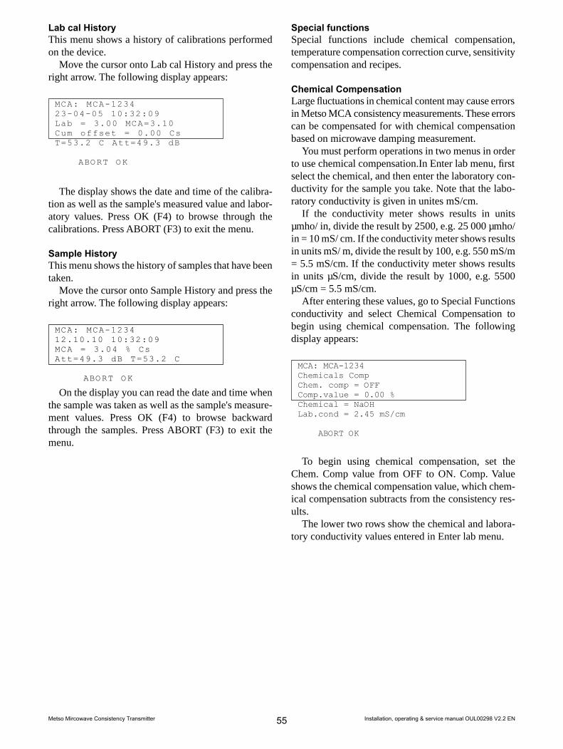
Lab cal HistoryThis menu shows a history of calibrations performedon the device.
Move the cursor onto Lab cal History and press theright arrow. The following display appears:
MCA: MCA-123423-04-05 10:32:09Lab = 3.00 MCA=3.10Cum offset = 0.00 CsT=53.2 C Att=49.3 dB
ABORT OK
The display shows the date and time of the calibra-tion as well as the sample's measured value and labor-atory values. Press OK (F4) to browse through thecalibrations. Press ABORT (F3) to exit the menu.
Sample HistoryThis menu shows the history of samples that have beentaken.
Move the cursor onto Sample History and press theright arrow. The following display appears:
MCA: MCA-123410:32:09
MCA = 3.04 % CsAtt=49.3 dB T=53.2 C
ABORT OK
12.10.10
On the display you can read the date and time whenthe sample was taken as well as the sample's measure-ment values. Press OK (F4) to browse backwardthrough the samples. Press ABORT (F3) to exit themenu.
Special functionsSpecial functions include chemical compensation,temperature compensation correction curve, sensitivitycompensation and recipes.
Chemical CompensationLarge fluctuations in chemical content may cause errorsin Metso MCA consistency measurements. These errorscan be compensated for with chemical compensationbased on microwave damping measurement.
You must perform operations in two menus in orderto use chemical compensation.In Enter lab menu, firstselect the chemical, and then enter the laboratory con-ductivity for the sample you take. Note that the labo-ratory conductivity is given in unites mS/cm.
If the conductivity meter shows results in unitsµmho/ in, divide the result by 2500, e.g. 25 000 µmho/in = 10 mS/ cm. If the conductivity meter shows resultsin units mS/ m, divide the result by 100, e.g. 550 mS/m= 5.5 mS/cm. If the conductivity meter shows resultsin units µS/cm, divide the result by 1000, e.g. 5500µS/cm = 5.5 mS/cm.
After entering these values, go to Special Functionsconductivity and select Chemical Compensation tobegin using chemical compensation. The followingdisplay appears:
MCA: MCA-1234Chemicals CompChem. comp = OFFComp.value = 0.00 %Chemical = NaOHLab.cond = 2.45 mS/cm
ABORT OK
To begin using chemical compensation, set theChem. Comp value from OFF to ON. Comp. Valueshows the chemical compensation value, which chem-ical compensation subtracts from the consistency res-ults.
The lower two rows show the chemical and labora-tory conductivity values entered in Enter lab menu.
Installation, operating & service manual OUL00298 V2.2 EN55Metso Mircowave Consistency Transmitter

Temperature Compensation Correction CurveYou can define temperature compensation correctioncurve for Metso MCA if you notice temperature depend-ency in the measurement results.
Define the correction curve by entering 2 - 6 pairsof temperature/consistency points. Based on the curvedrawn from these points, Metso MCA subtracts thecurve consistency from the measurement results.
Determine the correction curve pairs of points asdescribed in section 9.1. Then enter the pairs of pointsin the menu Temp Comp., which appears as follows:
MCA: MCA-1234Temp Comp1 #1 °C 0.002 #1 % 0.003 #2 °C 0.004 #2 % 0.00…9 #5 °C 0.00
#5 % 0.00#6 % 0.00#6 % 0.00
Enter temperature and consistency values for thedesired points (#1 - #6). Then press SEND (F2) to sendthe values to Metso MCA.
Sensitivity CorrectionMetso MCA consistency sensitivity is set according tothe wood fiber. The measurement sensitivity can bechanged if necessary, e.g. if you are measuring somematerial other than wood fiber.
If you do not know the sensitivity correction of thematerial beforehand, you can determine it accordingto the instructions in section 9.2 and enter it in the Sens.Corr. menu.
MCA: MCA-1234Sens Corr
1.001.00
DEL ESC ENTER
RecipesThe Recipe function may be necessary in specialfunctions in which measurement conditions change somuch that one calibration cannot cover it.
Such a change may be e.g.– A change in consistency greater than the device
measurement range ( 9 - 15 % depending on the typeof sensor).
– A change in the measured material, since differentmaterials have different consistency sensitivity.
– A large chemical fluctuation (e.g. change of chem-ical type) that cannot be compensated for withchemical compensation.In these cases, each process condition has its own
calibration and configuration performed.This calibration and configuration is saved as its own
recipe. In addition to consistency calibration, for eachrecipe you can set chemical compensation, temperatureconsistency correction, sensitivity correction, and cur-rent output scaling. You can save a maximum of fourrecipes.
The Recipes menu is as follows:
MCA: MCA-1234Recipes1 Choose: OFF
In Choose, set the desired recipe number. The op-tions are as follows:– OFF: the recipe function is not in use (default),– 1, 2, 3, 4: select the recipe number,– BIN: select the recipe according to binary input.
Select the recipe. Then perform recipe calibrationand current output scaling. Begin using the recipes asfollows:
When you use the recipe selection method ‘BIN’,connect the automation system digital control lines tothe TCU connector casing binary inputs BIN0 ANDBIN1. Connect their grounded line to BINGND. Selectthe recipe with the digital output lines according to thefollowing table:
BIN0 BIN1 Recipe0 0 11 0 20 1 31 1 4
Installation, operating & service manual OUL00298 V2.2 EN56Metso Mircowave Consistency Transmitter

12.5. DiagnosticsMenu information and functions:
MCA: MCA-1234Diagnostics1 Diag History2 Diag Values3 Diag Alarms4 Digital Inputs5 Loop test6 Clear Logs
Diag History: The 10 most recent self-diagnosticsalarms with beginning and ending times.
Diag values: Measured values of diagnostics variables(see Chapter 8.2).
Diag Alarms: Diagnostics variables´ alarm limits;switching alarms on and off (see Chapter 8.3).
Digital Inputs: The state of TCU binary inputs BIN0and BIN1.
Loop test: Forcing the output signal to the desiredvalue.
Master Reset: Resets the TCU. Similar to poweringthe TCU off, calibration is not discarded.
Status, Status nxt: State of diagnostics variables(alarm on/off).
Installation, operating & service manual OUL00298 V2.2 EN57Metso Mircowave Consistency Transmitter

Notes
Installation, operating & service manual OUL00298 V2.2 EN58Metso Mircowave Consistency Transmitter

13. Upgrade Kit for MCAi13.1. StructureUpgrade Kit for MCAi allows you to upgrade MCAito contain Metso MCA's performance and diagnosticscharacteristics. It consists of new Metso MCA sensorelectronics and the user interface, which is calledTransmitter Central Unit (TCU).
The part that is connected to the sensor consists ofsensor electronics and an adapter plate, with which theelectronics is installed into the Metso MCA base plate.
In addition, the sensor unit includes a separate cableassembly, with which you can install the sensor cable'sconnector on the base plate. The sensor cable is connec-ted to the TCU connector casing. The delivery also in-cludes shield plugs with which to replace the removedcables in the base plate inlet bushings.
Fig. 1. Upgrade Kit for MCAi structure.
13.2. Electrical connections
NOTE: The Upgrade Kit's current output is passive andneeds an external power source. In MCAi the currentoutput is active, so in the upgrade you must also makechanges to the network connection.
NOTE: When you connect power supply cables, makesure that the cables are disconnected from the powersupply.
NOTE: Connect the cables to the power supply only afteryou have checked all connections.
Refer to Chapter 3.5.
Installation, operating & service manual OUL00298 V2.2 EN59Metso Mircowave Consistency Transmitter
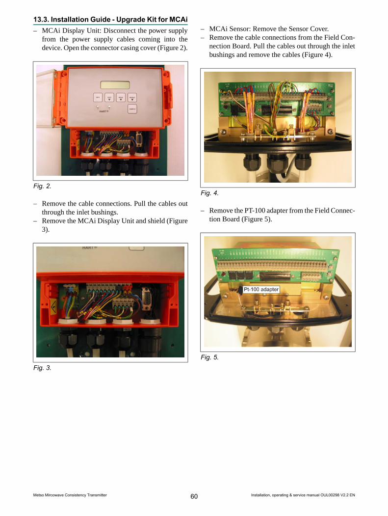
13.3. Installation Guide - Upgrade Kit for MCAi– MCAi Display Unit: Disconnect the power supply
from the power supply cables coming into thedevice. Open the connector casing cover (Figure 2).
Fig. 2.
– Remove the cable connections. Pull the cables outthrough the inlet bushings.
– Remove the MCAi Display Unit and shield (Figure3).
Fig. 3.
– MCAi Sensor: Remove the Sensor Cover.– Remove the cable connections from the Field Con-
nection Board. Pull the cables out through the inletbushings and remove the cables (Figure 4).
Fig. 4.
– Remove the PT-100 adapter from the Field Connec-tion Board (Figure 5).
Fig. 5.
Installation, operating & service manual OUL00298 V2.2 EN60Metso Mircowave Consistency Transmitter

– Remove the microwave cables from the sensorelectronics with an SMA wrench (figure 6).
Fig. 6.
– Remove the 4 mounting screws and lift the electron-ics off (Figure 7).
Fig. 7.
– Remove the cable inlet bushing from the base plate(Figure 8).
Fig. 8.
– In place of the inlet bushing insert an adapter as-sembly that has an adapter bushing, Metso MCAsensor adapter and power cable. Pay attention to getthe adapter assembly on the right threads.
– Insert shield plugs PG16 and PG21 into the openinlet bushings (Figure 9).
Fig. 9.
Installation, operating & service manual OUL00298 V2.2 EN61Metso Mircowave Consistency Transmitter

– Install the Upgrade Kit with 4 M6x20 screws (12).Use locking medium.
– Connect the microwave cables (13) with an SMAwrench.
– Connect the Pt-100 cable (14) to the Upgrade Kitadapter.
– Connect the power cable (15).– Put the Sensor Cover in place (Figure 10).
Fig. 10.
– Attach TCU (Metso MCA) to the wall (Figure 11).
Fig. 11.
– Connect the cables according to the instructions insection 3.5 of this User Guide. Note that you needan external power source to the current output be-cause Metso MCA's current output is passive.MCAi's current output is active (Figure 12).
Fig. 12.
– Pull the Sensor Cable to the sensor and connect itto the adapter you installed in the sensor's base plate.
– Perform startup according to the instructions in theUser Guide (Figure 13).
Fig. 13.
Installation, operating & service manual OUL00298 V2.2 EN62Metso Mircowave Consistency Transmitter
13.5. StartupRefer to section 4.In Upgrade Kit for MCAi startup, however, please notethe following:1. Upgrade Kit for MCAi is not factory calibrated.2. Calibration must be performed at the installation
site.3. You must know the sensor type for which MCAi
is to be installed. This information is found nextto Item on the sensor plate.
13.6. Configuration and Calibration1. Connect the electricity to the power supply feed.2. The device asks you to select the sensor type from
SET DEFAULT menu.3. Press EDIT/SAVE button.4. Select the sensor type using the up and down ar-
rows. You can recognize the Upgrade Kit sensorsfrom the UPG prefix. The options are:UPG FUPG FSUPG FT-100UPG FT-150UPG FT-200UPG FT-250UPG FT-300
5. Save your selection with EDIT/SAVE button.6. Select the language and temperature unit (°C/°F)
according to the instructions in chapter 6.3.7. Set the device date and time according to the in-
structions in chapter 6.5.8. Scale the current output according to the instruc-
tions in 6.2.9. Calibrate the consistency according to the instruc-
tions in 7.2 and 7.3.After you perform these steps, MCAi upgraded with
the Upgrade Kit is ready to measure.
13.7. User InterfaceRefer to section 5.
13.8. Troubleshooting and MaintenanceFor electronics issues, refer to section 10.
For sensor body, antenna and antenna cable issues,refer to section 11.
Installation, operating & service manual OUL00298 V2.2 EN63Metso Mircowave Consistency Transmitter

Notes
Installation, operating & service manual OUL00298 V2.2 EN64Metso Mircowave Consistency Transmitter

14. Recycling and disposing of a device re-moved from service
Most device parts are recyclable when sorted by material. A materials list must accompany the device. The devicemanufacturer can supply you with recycling and disposal instructions. In addition, you can return the device tothe manufacturer, which will recycle and dispose of the device for a fee.
Installation, operating & service manual OUL00298 V2.2 EN65Metso Mircowave Consistency Transmitter

Notes
Installation, operating & service manual OUL00298 V2.2 EN66Metso Mircowave Consistency Transmitter
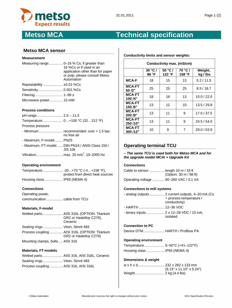
31.01.2011 Page 1 (2)
Metso MCA Technical specification
© Metso Automation Manufacturer reserves the right to changes without prior notice. MCA Specification EN.docx
Metso MCA sensorMeasurementMeasuring range.............. 0–16 % Cs; if greater than
16 %Cs or if used in anapplication other than for paperor pulp, please consult MetsoAutomation
Repeatability ................... ±0.01 %CsSensitivity ........................ 0.001 %CsFiltering ........................... 1–99 sMicrowave power............. 15 mW
Process conditionspH range ......................... 2.5 – 11.5Temperature.................... 0…+100 °C (32…212 °F)Process pressure- Minimum ....................... recommended: over > 1.5 bar,
no free air- Maximum, F-model ........ PN25- Maximum, FT-model ...... DIN PN16 / ANSI Class 150 /
JIS 10kVibration .......................... max. 20 m/s2, 10–2000 Hz
Operating environmentTemperature.................... -20...+70 °C (-4…+158 °F),
protect from direct heat sourcesHousing class .................. IP65 (NEMA 4)
ConnectionsOperating power,communication ................ cable from TCU
Materials, F-modelWetted parts .................... AISI 316L (OPTION: Titanium
GR2 or Hastelloy C276),Ceramic
Sealing rings ................... Viton, Simrit 483Process coupling ............. AISI 316L (OPTION: Titanium
GR2 or Hastelloy C276)Mounting clamps, bolts .... AISI 316
Materials, FT-modelsWetted parts .................... AISI 316, AISI 316L, CeramicSealing rings ................... Viton, Simrit 483Process coupling ............. AISI 316, AISI 316L
Conductivity limits and sensor weights:
Conductivity max. (mS/cm)
30 °C /86 °F
50 °C /122 °F
70 °C /158 °F
Weight, kg / lbs
MCA-F 18 15 13 5.2 / 11.5
MCA-FT50 /2" 25 25 25 8.5 / 18.7
MCA-FT100 /4" 18 16 13 10.0 / 22.0
MCA-FT150 /6" 13 12 10 13.5 / 29.8
MCA-FT200 /8" 13 11 9 17.0 / 37.5
MCA-FT250 /10" 13 11 9 24.5 / 54.0
MCA-FT300 /12" 10 9 7 29.0 / 63.9
Operating terminal TCU– The same TCU is used both for Metso MCA and forthe upgrade model MCAi + Upgrade Kit
ConnectionsCable to sensor ............... length 10 m / 33 ft
(Option: 30 m / 98 ft)Operating voltage ............ 90–260 VAC / 0.1 VA
Connections to mill systems- analog outputs ............... 2 current outputs, 4–20 mA (Cs
+ process temperature /conductivity)
- HART® ......................... 12–36 VDC- binary inputs .................. 2 x 12–28 VDC / 10 mA,
isolated
Connection to PCDevice DTM..................... HART® / Profibus PA
Operating environmentTemperature .................... 5–50°C (+41–122°F)Housing class .................. IP65 (NEMA 4)
Dimensions & weightw x h x d .......................... 232 x 282 x 133 mm
(9.13" x 11.10" x 5.24")Weight ............................. 2 kg (4.4 lbs)

Page 2 (2)
Metso MCA Technical specification
© Metso Automation Manufacturer reserves the right to changes without prior notice. MCA Specification EN.docx
MCAi + Upgrade KitMeasurementMeasuring range.............. 0–16 % Cs; if greater than
16 %Cs or if used in anapplication other than for paperor pulp, please consult MetsoAutomation
Repeatability ................... ±0.01 %CsSensitivity ........................ 0.001 %CsFiltering ........................... 1–99 sMicrowave power............. 15 mWCv-values- FT 200/8” ...................... 4200 (± 7.2%)- FT 250/10” .................... 7800 (± 2.4%)- FT 300/12” .................... 9700 (± 7.2%)
Process conditionspH range ......................... 2.5 – 11.5Temperature.................... 0…+100 °C (32…212 °F)Process pressure- Minimum ....................... recommended: over > 1.5 bar,
no free air- Maximum, F-model ........ PN25- Maximum, FT-model ...... DIN PN16 / ANSI Class 150 /
JIS 10kVibration .......................... max. 20 m/s2, 10–2000 Hz
EnvironmentTemperature.................... -20...+70 °C (-4…+158 °F),
protect from direct heat sourcesHousing class .................. IP65 (NEMA 4)
ConnectionsOperating power,communication ................ cable from TCU
Materials, F- & FS-modelsSensor ............................ AISI 316L (OPTION: Titanium
GR2 or Hastelloy C276),Titanium, Ceramic
Process coupling ............. L-coupling, AISI 316L (OPTION:Titanium GR2 or HastelloyC276)
Materials, FT-modelSensor ............................ AISI 316L, Titanium, CeramicProcess coupling:- FT100/4" ....................... fixed flange machined
according to DIN, ANSI or JISstandard
- FT150/6", FT200/8" ....... no flange- FT250/10", FT300&12" . fixed flange machined
according to DIN, ANSI or JISstandard
Conductivity limits and sensor weights:
Conductivity max. (mS/cm)
30 °C /86 °F
50 °C /122 °F
70 °C /158 °F
Weight, kg / lbs
MCAi F 17 14 12 12.0 / 26.5
MCAi FS 20 17 15 12.0 / 26.5
MCA-FT100 /4" 18 16 13 23.0 / 50.7
MCA-FT150 /6" 13 12 10 23.0 / 50.7
MCA-FT200 /8" 13 11 9 28.0 / 61.7
MCA-FT250 /10" 13 11 9 87.0 /
191.8MCA-FT300 /12" 9 8 6 91.0 /
200.6
After the upgrade there is no more a conductivity lowlimit for the MCAi FT 100/4” sensor.

31.01.2011 Page 1 (4)
Metso MCA Service kits & spare parts
© Metso Automation Manufacturer reserves the right to changes without prior notice.
Metso MCA Service Kit OUL00335Order Code Description QtyOUL00347 Accessory Case 1OUL00298 Manual 1OUL00051 Sensor Electronics 1OUL00241 Operating Unit TCU 1OUL00334 Simulation Cable 1OUL00325 Tool for Sensor Head 1OUL00323 Tool for Fork Pt-100 Cap 1A4611042 Sma Torque Wrench Modified 1OUL00407 Sma Torque Wrench Adapter 1OUL00349 Torque Driver 1/4" 1OUL00409 Box Key 10 mm 183200021 Thread Locking Compound Loctite 270 10 ml8360019 Instant Glue Loctite 480 20 gOUL00350 Thermoelement Simulator 1
OUL00351 Spare Part Set MCA F 1OUL00007 O-Ring 13.1x1.6 Simrit 483 5OUL00198 O-Ring 23.4x3.5 Viton 580500860 Gasket Ptfe 5OUL00277 O-Ring 90x3 Epdm 55060011 Lock Washer DIN127-B4 A4 55060013 Lock Washer DIN127-B6 A4 55060014 Lock Washer DIN127-B8 A4 55160011 Slot head Screw DIN84-M4x16 A4 55460041 Socket Head Screw DIN912-M6x20 A4 5OUL00003 Socket Head Screw DIN912-M8x20 A4 5
OUL00352 Spare Part Set MCA FT 18060036 O-Ring 14.3x2.4 Simrit 483 5OUL00198 O-Ring 23.4x3.5 Viton 5OUL00182 O-Ring 33x2.62 Viton 5OUL00184 O-Ring 56.2x3.0 Viton 5OUL00294 Seal Ring 16x10x1 Polyamide 10OUL00183 Seal Washer U6.7x11.0x1 55060011 Lock Washer DIN127-B4 A4 55060013 Lock Washer DIN127-B6 A4 501100364 Rec Countersunk Screw DIN965-M3x12 55160025 Slot head Screw DIN84-M4x8 A4 55160015 Slot head Screw DIN84-M4x12 A4 5OUL00185 Socket Head Screw DIN912-M6x16 A4 5

Page 2 (4)
Metso MCA Service kits & spare parts
© Metso Automation Manufacturer reserves the right to changes without prior notice.
Service Kit Options, MCA-F AISI 316LOrder Code DescriptionOUL00339 Microwave Cable Set FOUL00046 Microwave Antenna AISI 316LOUL00010 Sensor Head AISI 316LOUL00016 Thermoelement Assembly F AISI 316LService Kit Options, MCA-F Titanium Gr.2Order Code DescriptionOUL00339 Microwave Cable Set FOUL00259 Microwave Antenna TitaniumOUL00263 Sensor Head TitaniumOUL00267 Thermoelement Assembly F TitaniumService Kit Options, MCA-F Hastelloy C-276Order Code DescriptionOUL00339 Microwave Cable Set FOUL00260 Microwave Antenna HastelloyOUL00264 Sensor Head HastelloyOUL00268 Thermoelement Assembly F HastelloyService Kit Options, MCA-FTOrder Code DescriptionOUL00420 Microwave Cable FT-50/2"OUL00114 Microwave Cable FT-100/4"OUL00118 Microwave Cable FT-150/6"OUL00194 Microwave Cable FT-200/8"OUL00197 Microwave Cable FT-250/10"OUL00216 Microwave Cable FT-300/12"OUL00178 Thermoelement Assembly FTOUL00046 Microwave Antenna AISI 316L

Page 3 (4)
Metso MCA Service kits & spare parts
© Metso Automation Manufacturer reserves the right to changes without prior notice.
Spare parts, MCA-FTPart Order Code Description Pcs
1 OUL00278 Sensor Cover 12 OUL00051 Sensor Electronics 13 OUL00271 Assembly Set FT 14 OUL00178 Thermoelement Assembly FT 15 OUL00294 Seal Ring 2
6
OUL00420 Microwave Cable FT-50/2" 2OUL00114 Microwave Cable FT-100/4" 2OUL00118 Microwave Cable FT-150/6" 2OUL00194 Microwave Cable FT-200/8" 2OUL00197 Microwave Cable FT-250/10" 2OUL00216 Microwave Cable FT-300/12" 2
7 OUL00198 O-Ring 23.4x3.5 Viton 28 OUL00046 Microwave Antenna AISI 316L 2
9
OUL00189 Antenna Cover (FT-150, FT-200, FT-250, FT-300) 2OUL00180 Antenna Cover (FT-50, FT-100) FT-50: 1 / FT-100: 2OUL00422 Antenna Cover (FT-50, attenuator side) 1OUL00428 Attenuator 10 dB (FT-50) 1OUL00213 Gasket (FT-50, FT-100) 2
10 OUL00185 Screw DIN912-M6x16 A4-70 12233778 Screw DIN912-M6x20 A4-70 (FT-50, FT-100) 8
11 5060013 Washer DIN127-B6 A4 1212 5160015 Screw DIN84-M4x12 A4 413 5060011 Washer DIN127-B4 A4 1214 5160025 Screw DIN84-M4x8 A4 8
1
2
4
5
6
7
9
10 11
12 1314 13
8
3

Page 4 (4)
Metso MCA Service kits & spare parts
© Metso Automation Manufacturer reserves the right to changes without prior notice.
Spare parts, MCA-FPart Order Code Description Pcs
1 OUL00278 Sensor Cover 12 OUL00051 Sensor Electronics 13 OUL00276 Assembly Set F 1
4OUL00046 Microwave Antenna AISI 316L 1OUL00259 Microwave Antenna Titanium Gr.2 1OUL00260 Microwave Antenna Hastelloy 1
5OUL00010 Sensor Head AISI 316L 1OUL00263 Sensor Head Titanium Gr. 2 1OUL00264 Sensor Head Hastelloy 1
6OUL00016 Thermoelement Assembly AISI 316L 1OUL00267 Thermoelement Assembly Titanium 1OUL00268 Thermoelement Assembly Hastelloy 1
7 OUL00339 Microwave Cable Set F 18 OUL00198 O-Ring 23.4x3.5 Viton 19 OUL00003 Screw DIN912-M8x20 A4-70 2
10 5060014 Washer DIN127-B8 A4 211 5160011 Screw DIN84-M4x16 212 5060011 Washer DIN127-B4 A4 213 5460041 Screw DIN912-M6x20 A4-70 614 5060013 Washer DIN127-B6 A4 6
12
3
4
5
9 10
8
11 12
13 14
6
7


Metso Automation Inc., Kehräämöntie 3, P.O.Box 177, FI-87101 Kajaani, FinlandTel. +358 20 483 120, fax +358 20 483 121, www.metso.com/automation
This document discloses subject matter in which the manufacturer has proprietary rights. Neither receipt nor possession thereof confers or transfers any right to reproduce or disclose the document, any part thereof, any physical article or device, except by written permission from the manufacturer. Manufacturer reserves the right to alter the contents of this document without prior notice.Modbus is the trademark of Modicon Inc.
Copyright © March 2011
Metso Automation Inc.Documentation: JT-Tieto Oy