Metric Hydraulic Cylinders - · PDF fileMetric Hydraulic Cylinders ... IL USA ... ISO...
44
aerospace climate control electromechanical filtration fluid & gas handling hydraulics pneumatics process control sealing & shielding Metric Hydraulic Cylinders Series AHM www.comoso.com
Transcript of Metric Hydraulic Cylinders - · PDF fileMetric Hydraulic Cylinders ... IL USA ... ISO...
aerospaceclimate control electromechanicalfiltrationfluid & gas handlinghydraulicspneumaticsprocess controlsealing & shielding
Metric Hydraulic CylindersSeries AHM
www.comoso.com
Metric Hydraulic CylindersSeries AHM
Catalog HY04-AC1151-1/NA
� Atlas CylindersDes Plaines, IL USA
www.AtlasCylinders.com
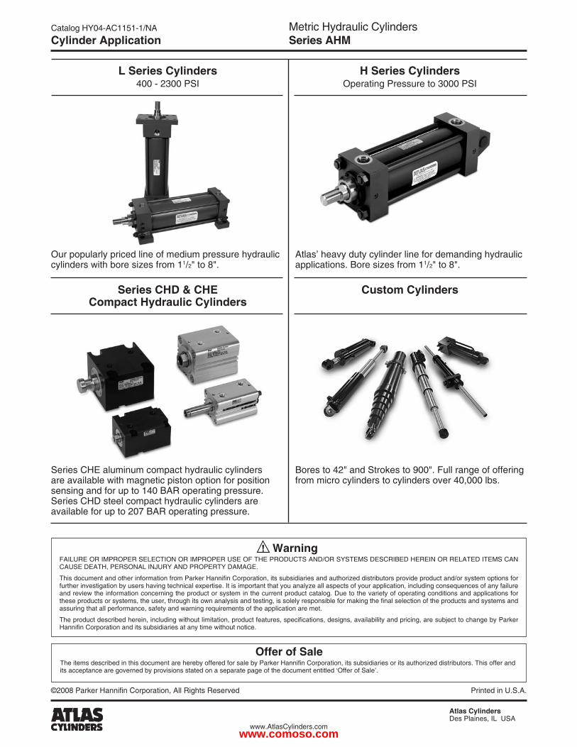
Cylinder Application
Bores to 4�" and Strokes to 900". Full range of offering from micro cylinders to cylinders over 40,000 lbs.
Custom Cylinders
Our popularly priced line of medium pressure hydraulic cylinders with bore sizes from 11/�" to 8".
Atlas’ heavy duty cylinder line for demanding hydraulic applications. Bore sizes from 11/�" to 8".
©�008 Parker Hannifin Corporation, All Rights Reserved Printed in U.S.A.
Series CHD & CHE Compact Hydraulic Cylinders
Series CHE aluminum compact hydraulic cylinders are available with magnetic piston option for position sensing and for up to 140 BAR operating pressure. Series CHD steel compact hydraulic cylinders are available for up to �07 BAR operating pressure.
Offer of SaleThe items described in this document are hereby offered for sale by Parker Hannifin Corporation, its subsidiaries or its authorized distributors. This offer and its acceptance are governed by provisions stated on a separate page of the document entitled ‘Offer of Sale’.
WarningFAILURE OR IMPROPER SELECTION OR IMPROPER USE OF THE PRODUCTS AND/OR SYSTEMS DESCRIBED HEREIN OR RELATED ITEMS CAN CAUSE DEATH, PERSONAL INJURY AND PROPERTY DAMAGE.
This document and other information from Parker Hannifin Corporation, its subsidiaries and authorized distributors provide product and/or system options for further investigation by users having technical expertise. It is important that you analyze all aspects of your application, including consequences of any failure and review the information concerning the product or system in the current product catalog. Due to the variety of operating conditions and applications for these products or systems, the user, through its own analysis and testing, is solely responsible for making the final selection of the products and systems and assuring that all performance, safety and warning requirements of the application are met.
The product described herein, including without limitation, product features, specifications, designs, availability and pricing, are subject to change by Parker Hannifin Corporation and its subsidiaries at any time without notice.
H Series Cylinders Operating Pressure to 3000 PSI
L Series Cylinders 400 - �300 PSI
www.comoso.com
Metric Hydraulic CylindersSeries AHM
Catalog HY04-AC1151-1/NA
1 Atlas CylindersDes Plaines, IL USA
www.AtlasCylinders.com
Table of Contents
Table of Contents Page No.
Contents
Introduction .....................................................................................................................................................................2
Features, Specifications and Mountings .........................................................................................................................3
Design Features and Benefits .....................................................................................................................................4-5
Mounting Styles...............................................................................................................................................................6
Piston Rod End Data / Thread Styles .............................................................................................................................7
Cylinder Dimensions ..................................................................................................................................................8-11
Double Rod Cylinders ...................................................................................................................................................12
Accessories ..............................................................................................................................................................13-15
Model Numbers ........................................................................................................................................................16-17
End-of-Stroke Proximity Sensors .............................................................................................................................18-24
Parts Identification .........................................................................................................................................................25
Seal Kits ........................................................................................................................................................................26
Mounting Information ...............................................................................................................................................27-28
Theoretical Push and Pull Forces ................................................................................................................................29
Piston Rod Sizes / Stop Tubes .....................................................................................................................................30
Stroke Factors ...............................................................................................................................................................31
Cushioning ....................................................................................................................................................................32
Cushion Energy ............................................................................................................................................................33
Cushioning / Pressure Limitations ................................................................................................................................34
Ports ..............................................................................................................................................................................35
Ports / Weights ..............................................................................................................................................................36
Seals and Fluids............................................................................................................................................................37
Optional Features .........................................................................................................................................................38
Cylinder Safety Guide ..............................................................................................................................................39-40
Offer of Sale ..................................................................................................................................................................41
www.comoso.com
Metric Hydraulic CylindersSeries AHM
Catalog HY04-AC1151-1/NA
� Atlas CylindersDes Plaines, IL USA
www.AtlasCylinders.com
Introduction
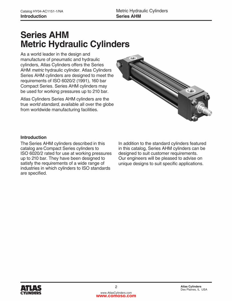
As a world leader in the design and manufacture of pneumatic and hydraulic cylinders, Atlas Cylinders offers the Series AHM metric hydraulic cylinder. Atlas Cylinders Series AHM cylinders are designed to meet the requirements of ISO 60�0/� (1991), 160 bar Compact Series. Series AHM cylinders may be used for working pressures up to �10 bar.
Atlas Cylinders Series AHM cylinders are the true world standard, available all over the globe from worldwide manufacturing facilities.
IntroductionThe Series AHM cylinders described in this catalog are Compact Series cylinders to ISO 60�0/� rated for use at working pressures up to �10 bar. They have been designed to satisfy the requirements of a wide range of industries in which cylinders to ISO standards are specified.
In addition to the standard cylinders featured in this catalog, Series AHM cylinders can be designed to suit customer requirements. Our engineers will be pleased to advise on unique designs to suit specific applications.
Series AHM Metric Hydraulic Cylinders
www.comoso.com
Metric Hydraulic CylindersSeries AHM
Catalog HY04-AC1151-1/NA
3 Atlas CylindersDes Plaines, IL USA
www.AtlasCylinders.com
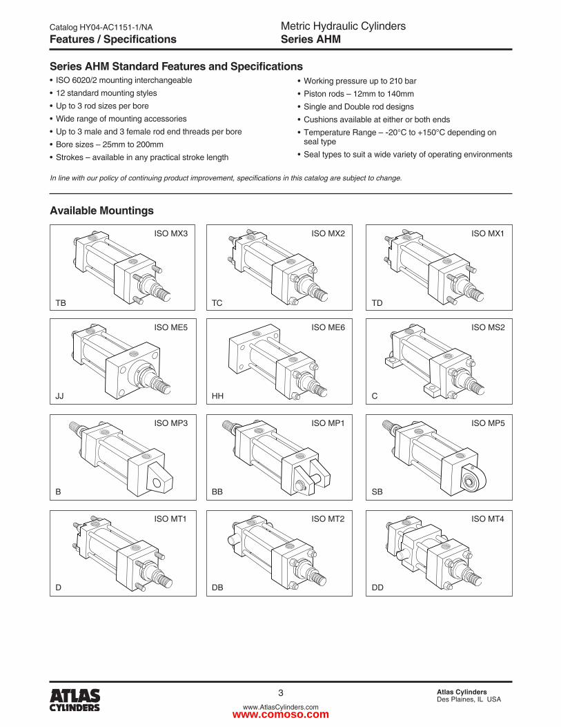
Series AHM Standard Features and Specifications• ISO 60�0/� mounting interchangeable• 1� standard mounting styles• Up to 3 rod sizes per bore• Wide range of mounting accessories• Up to 3 male and 3 female rod end threads per bore• Bore sizes – �5mm to �00mm• Strokes – available in any practical stroke length
• Working pressure up to �10 bar• Piston rods – 1�mm to 140mm• Single and Double rod designs• Cushions available at either or both ends• Temperature Range – -�0°C to +150°C depending on seal type• Seal types to suit a wide variety of operating environments
Available Mountings
In line with our policy of continuing product improvement, specifications in this catalog are subject to change.
ISO MX1
ISO MS�
ISO MP5
ISO MT4
ISO MX3
TB
ISO ME5
JJ
ISO MP3
B
ISO MT1
D
ISO MX�
TC
ISO ME6
HH
ISO MP1
BB
ISO MT�
DB
TD
C
SB
DD
Features / Specifications
www.comoso.com
Metric Hydraulic CylindersSeries AHM
Catalog HY04-AC1151-1/NA
4 Atlas CylindersDes Plaines, IL USA
www.AtlasCylinders.com
1
23 5 6 8
977 & 84
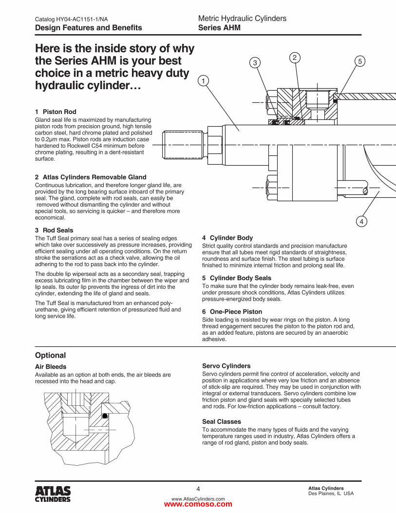
1 Piston RodGland seal life is maximized by manufacturing piston rods from precision ground, high tensile carbon steel, hard chrome plated and polished to 0.�µm max. Piston rods are induction case hardened to Rockwell C54 minimum before chrome plating, resulting in a dent-resistant surface.
Here is the inside story of why the Series AHM is your best choice in a metric heavy duty hydraulic cylinder…
4 Cylinder BodyStrict quality control standards and precision manufacture ensure that all tubes meet rigid standards of straightness, roundness and surface finish. The steel tubing is surface finished to minimize internal friction and prolong seal life.
5 Cylinder Body SealsTo make sure that the cylinder body remains leak-free, even under pressure shock conditions, Atlas Cylinders utilizes pressure-energized body seals.
6 One-Piece PistonSide loading is resisted by wear rings on the piston. A long thread engagement secures the piston to the piston rod and, as an added feature, pistons are secured by an anaerobic adhesive.
2 Atlas Cylinders Removable GlandContinuous lubrication, and therefore longer gland life, are provided by the long bearing surface inboard of the primary seal. The gland, complete with rod seals, can easily be removed without dismantling the cylinder and without special tools, so servicing is quicker – and therefore more economical.
3 Rod SealsThe Tuff Seal primary seal has a series of sealing edges which take over successively as pressure increases, providing efficient sealing under all operating conditions. On the return stroke the serrations act as a check valve, allowing the oil adhering to the rod to pass back into the cylinder.
The double lip wiperseal acts as a secondary seal, trapping excess lubricating film in the chamber between the wiper and lip seals. Its outer lip prevents the ingress of dirt into the cylinder, extending the life of gland and seals.
The Tuff Seal is manufactured from an enhanced poly-urethane, giving efficient retention of pressurized fluid and long service life.
Servo CylindersServo cylinders permit fine control of acceleration, velocity and position in applications where very low friction and an absence of stick-slip are required. They may be used in conjunction with integral or external transducers. Servo cylinders combine low friction piston and gland seals with specially selected tubes and rods. For low-friction applications – consult factory.
Seal ClassesTo accommodate the many types of fluids and the varying temperature ranges used in industry, Atlas Cylinders offers a range of rod gland, piston and body seals.
OptionalAir BleedsAvailable as an option at both ends, the air bleeds are recessed into the head and cap.
Design Features and Benefits
www.comoso.com
Metric Hydraulic CylindersSeries AHM
Catalog HY04-AC1151-1/NA
5 Atlas CylindersDes Plaines, IL USA
www.AtlasCylinders.com
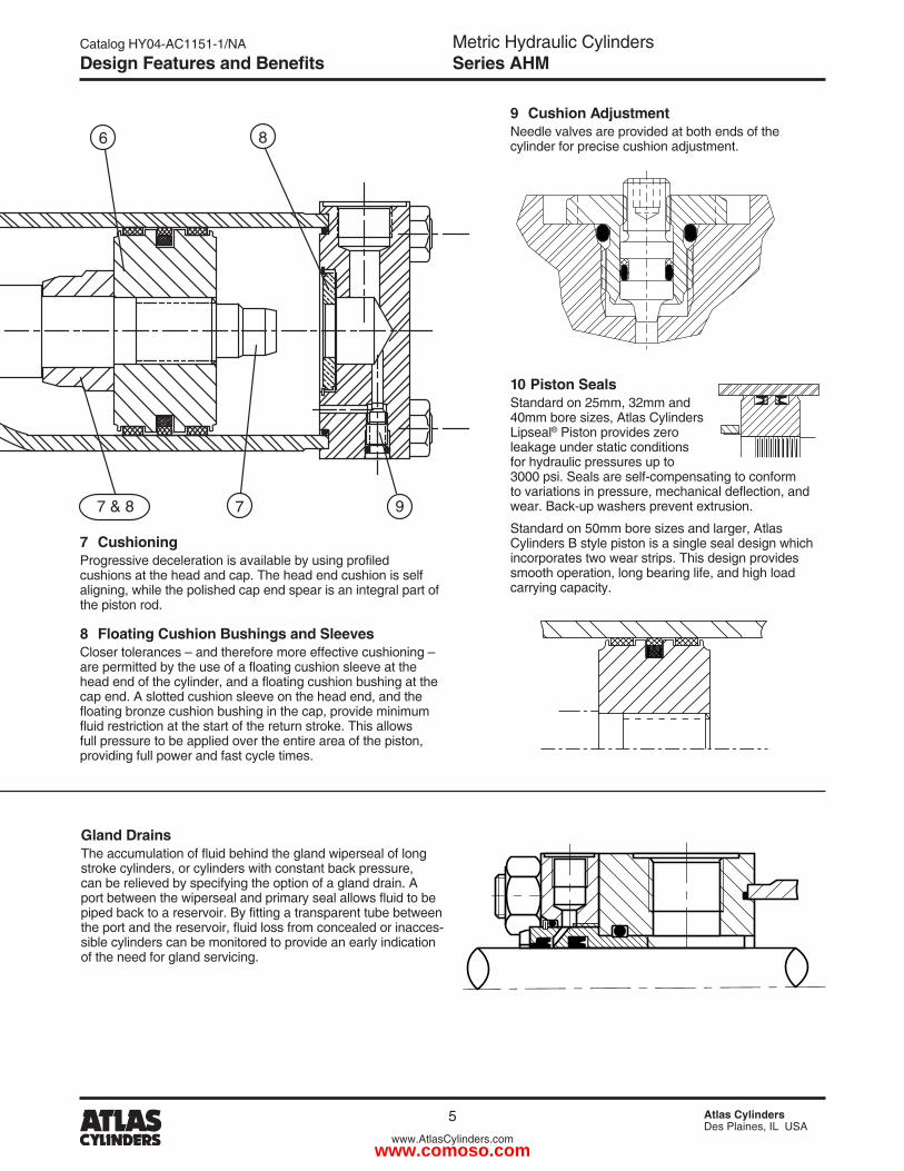
7 CushioningProgressive deceleration is available by using profiled cushions at the head and cap. The head end cushion is self aligning, while the polished cap end spear is an integral part of the piston rod.
8 Floating Cushion Bushings and SleevesCloser tolerances – and therefore more effective cushioning – are permitted by the use of a floating cushion sleeve at the head end of the cylinder, and a floating cushion bushing at the cap end. A slotted cushion sleeve on the head end, and the floating bronze cushion bushing in the cap, provide minimum fluid restriction at the start of the return stroke. This allows full pressure to be applied over the entire area of the piston, providing full power and fast cycle times.
1
23 5 6 8
977 & 84
9 Cushion AdjustmentNeedle valves are provided at both ends of the cylinder for precise cushion adjustment.
Gland DrainsThe accumulation of fluid behind the gland wiperseal of long stroke cylinders, or cylinders with constant back pressure, can be relieved by specifying the option of a gland drain. A port between the wiperseal and primary seal allows fluid to be piped back to a reservoir. By fitting a transparent tube between the port and the reservoir, fluid loss from concealed or inacces-sible cylinders can be monitored to provide an early indication of the need for gland servicing.
10 Piston SealsStandard on �5mm, 3�mm and 40mm bore sizes, Atlas Cylinders Lipseal® Piston provides zero leakage under static conditions for hydraulic pressures up to 3000 psi. Seals are self-compensating to conform to variations in pressure, mechanical deflection, and wear. Back-up washers prevent extrusion.
Standard on 50mm bore sizes and larger, Atlas Cylinders B style piston is a single seal design which incorporates two wear strips. This design provides smooth operation, long bearing life, and high load carrying capacity.
Design Features and Benefits
www.comoso.com
Metric Hydraulic CylindersSeries AHM
Catalog HY04-AC1151-1/NA
6 Atlas CylindersDes Plaines, IL USA
www.AtlasCylinders.com
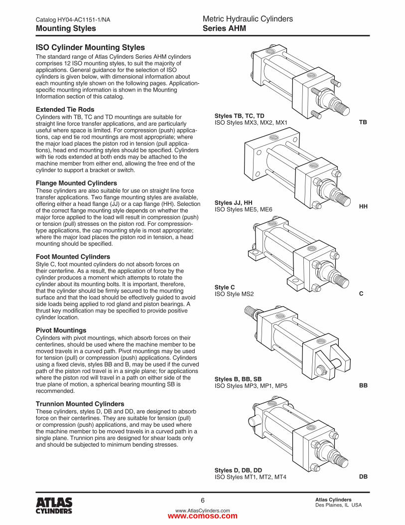
ISO Cylinder Mounting Styles The standard range of Atlas Cylinders Series AHM cylinders comprises 1� ISO mounting styles, to suit the majority of applications. General guidance for the selection of ISO cylinders is given below, with dimensional information about each mounting style shown on the following pages. Application-specific mounting information is shown in the Mounting Information section of this catalog.
Extended Tie Rods Cylinders with TB, TC and TD mountings are suitable for straight line force transfer applications, and are particularly useful where space is limited. For compression (push) applica-tions, cap end tie rod mountings are most appropriate; where the major load places the piston rod in tension (pull applica-tions), head end mounting styles should be specified. Cylinders with tie rods extended at both ends may be attached to the machine member from either end, allowing the free end of the cylinder to support a bracket or switch.
Flange Mounted Cylinders These cylinders are also suitable for use on straight line force transfer applications. Two flange mounting styles are available, offering either a head flange (JJ) or a cap flange (HH). Selection of the correct flange mounting style depends on whether the major force applied to the load will result in compression (push) or tension (pull) stresses on the piston rod. For compression-type applications, the cap mounting style is most appropriate; where the major load places the piston rod in tension, a head mounting should be specified.
Foot Mounted Cylinders Style C, foot mounted cylinders do not absorb forces on their centerline. As a result, the application of force by the cylinder produces a moment which attempts to rotate the cylinder about its mounting bolts. It is important, therefore, that the cylinder should be firmly secured to the mounting surface and that the load should be effectively guided to avoid side loads being applied to rod gland and piston bearings. A thrust key modification may be specified to provide positive cylinder location.
Pivot Mountings Cylinders with pivot mountings, which absorb forces on their centerlines, should be used where the machine member to be moved travels in a curved path. Pivot mountings may be used for tension (pull) or compression (push) applications. Cylinders using a fixed clevis, styles BB and B, may be used if the curved path of the piston rod travel is in a single plane; for applications where the piston rod will travel in a path on either side of the true plane of motion, a spherical bearing mounting SB is recommended.
Trunnion Mounted Cylinders These cylinders, styles D, DB and DD, are designed to absorb force on their centerlines. They are suitable for tension (pull) or compression (push) applications, and may be used where the machine member to be moved travels in a curved path in a single plane. Trunnion pins are designed for shear loads only and should be subjected to minimum bending stresses.
Styles TB, TC, TD ISO Styles MX3, MX�, MX1 TB
Styles JJ, HH ISO Styles ME5, ME6 HH
Style C ISO Style MS� C
Styles B, BB, SB ISO Styles MP3, MP1, MP5 BB
Styles D, DB, DD ISO Styles MT1, MT�, MT4 DB
Mounting Styles
www.comoso.com
Metric Hydraulic CylindersSeries AHM
Catalog HY04-AC1151-1/NA
7 Atlas CylindersDes Plaines, IL USA
www.AtlasCylinders.com
All dimensions are in millimeters unless otherwise stated.
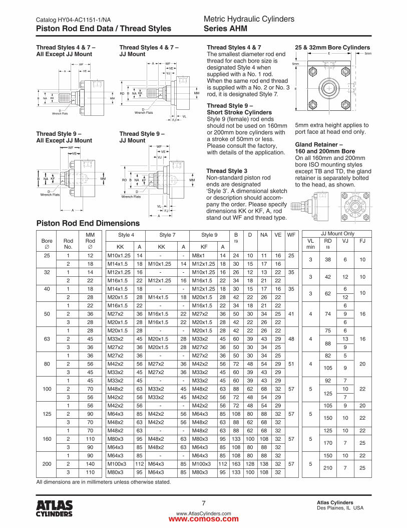
MM Style 4 Style 7 Style 9 B D NA VE WF JJ Mount Only Bore Rod Rod f9 VL RD VJ FJ No. KK A KK A KF A min f8
�5 1 1� M10x1.�5 14 - - M8x1 14 �4 10 11 16 �5 3 38 6 10
� 18 M14x1.5 18 M10x1.�5 14 M1�x1.�5 18 30 15 17 16 3� 1 14 M1�x1.�5 16 - - M10x1.�5 16 �6 1� 13 �� 35
3 4� 1� 10 � �� M16x1.5 �� M1�x1.�5 16 M16x1.5 �� 34 18 �1 �� 40 1 18 M14x1.5 18 - - M1�x1.�5 18 30 15 17 16 35
3 6� 6
10 � �8 M�0x1.5 �8 M14x1.5 18 M�0x1.5 �8 4� �� �6 �� 1� 1 �� M16x1.5 �� - - M16x1.5 �� 34 18 �1 �� 6 50 � 36 M�7x� 36 M16x1.5 �� M�7x� 36 50 30 34 �5 41 4 74 9 16 3 �8 M�0x1.5 �8 M16x1.5 �� M�0x1.5 �8 4� �� �6 �� 6 1 �8 M�0x1.5 �8 - - M�0x1.5 �8 4� �� �6 �� 75 6 63 � 45 M33x� 45 M�0x1.5 �8 M33x� 45 60 39 43 �9 48 4
88 13 16
3 36 M�7x� 36 M�0x1.5 �8 M�7x� 36 50 30 34 �5 9 1 36 M�7x� 36 - - M�7x� 36 50 30 34 �5 8� 5 80 � 56 M4�x� 56 M�7x� 36 M4�x� 56 7� 48 54 �9 51 4
105 9 �0
3 45 M33x� 45 M�7x� 36 M33x� 45 60 39 43 �9 1 45 M33x� 45 - - M33x� 45 60 39 43 �9 9� 7 100 � 70 M48x� 63 M33x� 45 M48x� 63 88 6� 68 3� 57 5
1�5 10 ��
3 56 M4�x� 56 M33x� 45 M4�x� 56 7� 48 54 �9 7 1 56 M4�x� 56 - - M4�x� 56 7� 48 54 �9 105 9 �0 1�5 � 90 M64x3 85 M4�x� 56 M64x3 85 108 80 88 3� 57 5
150 10 �� 3 70 M48x� 63 M4�x� 56 M48x� 63 88 6� 68 3� 1 70 M48x� 63 - - M48x� 63 88 6� 68 3� 1�5 10 �� 160 � 110 M80x3 95 M48x� 63 M80x3 95 133 100 108 3� 57 5
170 7 �5 3 90 M64x3 85 M48x� 63 M64x3 85 108 80 88 3� 1 90 M64x3 85 - - M64x3 85 108 80 88 3� 150 10 �� �00 � 140 M100x3 11� M64x3 85 M100x3 11� 163 1�8 138 3� 57 5
�10 7 �5 3 110 M80x3 95 M64x3 85 M80x3 95 133 100 108 3�
Thread Style 9 – Short Stroke CylindersStyle 9 (female) rod ends should not be used on 160mm or �00mm bore cylinders with a stroke of 50mm or less. Please consult the factory, with details of the application.
Thread Style 3Non-standard piston rod ends are designated ‘Style 3’. A dimensional sketch or description should accom-pany the order. Please specify dimensions KK or KF, A, rod stand out WF and thread type.
Gland Retainer – 160 and 200mm BoreOn all 160mm and �00mm bore ISO mounting styles except TB and TD, the gland retainer is separately bolted to the head, as shown.
Thread Styles 4 & 7The smallest diameter rod end thread for each bore size is designated Style 4 when supplied with a No. 1 rod. When the same rod end thread is supplied with a No. � or No. 3 rod, it is designated Style 7.
25 & 32mm Bore Cylinders
5mm extra height applies to port face at head end only.
Thread Styles 4 & 7 – All Except JJ Mount
Thread Style 9 – All Except JJ Mount
Thread Styles 4 & 7 – JJ Mount
Thread Style 9 – JJ Mount
Piston Rod End Dimensions
WF
A
B
DWrench Flats
NA KK MM
VE
B
A
RD NA KK
VE
VJ
VLFJ
WF
MM
DWrench Flats
WF
A
B
DWrench Flats
NA KF MM
VE
E
5mm
5mm
E
VE
VJ
VLFJ
WF
MMNABRD KF
D
Wrench Flats
A
Piston Rod End Data / Thread Styles
www.comoso.com
Metric Hydraulic CylindersSeries AHM
Catalog HY04-AC1151-1/NA
8 Atlas CylindersDes Plaines, IL USA
www.AtlasCylinders.com
BBDD G J
PJ + StrokeY
TG
AA4
1
2
3
TG
WF
WHEE
JZJ + Stroke
KBFT
E1
E1
KBG J
PJ + StrokeY
TG
AA4
E1
E1 2
1
3
TG
WF
EE
JZJ + Stroke
BBF
DD
BB G J
JPJ + StrokeY
TG
AA
E1
E1 4
1
2
3
TG
WF
WHEE
JZJ + Stroke
BBFT
DD
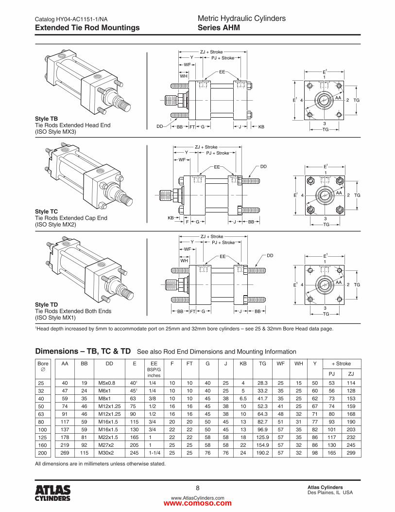
AA BB DD E EE F FT G J KB TG WF WH Y + Stroke BSP/G inches PJ ZJ
40 19 M5x0.8 401 1/4 10 10 40 �5 4 �8.3 �5 15 50 53 114 47 �4 M6x1 451 1/4 10 10 40 �5 5 33.� 35 �5 60 56 1�8 59 35 M8x1 63 3/8 10 10 45 38 6.5 41.7 35 �5 6� 73 153 74 46 M1�x1.�5 75 1/� 16 16 45 38 10 5�.3 41 �5 67 74 159 91 46 M1�x1.�5 90 1/� 16 16 45 38 10 64.3 48 3� 71 80 168 117 59 M16x1.5 115 3/4 �0 �0 50 45 13 8�.7 51 31 77 93 190 137 59 M16x1.5 130 3/4 �� �� 50 45 13 96.9 57 35 8� 101 �03 178 81 M��x1.5 165 1 �� �� 58 58 18 1�5.9 57 35 86 117 �3� �19 9� M�7x� �05 1 �5 �5 58 58 �� 154.9 57 3� 86 130 �45 �69 115 M30x� �45 1-1/4 �5 �5 76 76 �4 190.� 57 3� 98 165 �99
Style TB Tie Rods Extended Head End (ISO Style MX3)
Style TC Tie Rods Extended Cap End (ISO Style MX�)
Style TD Tie Rods Extended Both Ends (ISO Style MX1)
All dimensions are in millimeters unless otherwise stated.
1Head depth increased by 5mm to accommodate port on �5mm and 3�mm bore cylinders – see �5 & 3�mm Bore Head data page.
Dimensions – TB, TC & TD See also Rod End Dimensions and Mounting Information
�5 3� 40 50 63 80 100 1�5 160 �00
Bore
Extended Tie Rod Mountings
www.comoso.com
Metric Hydraulic CylindersSeries AHM
Catalog HY04-AC1151-1/NA
9 Atlas CylindersDes Plaines, IL USA
www.AtlasCylinders.com
G J
PJ + Stroke Y UO
TF
4
1
2
3
R
WF EE
J ZJ + Stroke
ZB + Stroke
KB
Ø FB (x4)
E
E2
KB G J
J PJ + Stroke Y
4
E
R 2
WF
EE
J ZJ + Stroke
F
Ø FB (x4)
UO
TF
1
3
E 1
KB
SWSW
XS
G J
PJ + Stroke
SS + Stroke
Y
4 2
WF EE
JZB + Stroke
F
Ø SB(HEAD)
TS
US
1
3
LH
E
E2
ST
Z
ZJ + Stroke
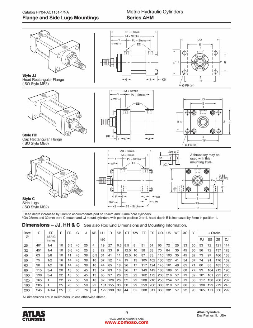
E EE F FB G J KB LH R SB ST SW TF TS UO US WF XS Y + Stroke BSP/G inches h10 PJ SS ZB ZJ
401 1/4 10 5.5 40 �5 4 19 �7 6.6 8.5 8 51 54 65 7� �5 33 50 53 7� 1�1 114 451 1/4 10 6.6 40 �5 5 �� 33 9 1�.5 10 58 63 70 84 35 45 60 56 7� 137 1�8 63 3/8 10 11 45 38 6.5 31 41 11 1�.5 10 87 83 110 103 35 45 6� 73 97 166 153 75 1/� 16 14 45 38 10 37 5� 14 19 13 105 10� 130 1�7 41 54 67 74 91 176 159 90 1/� 16 14 45 38 10 44 65 18 �6 17 117 1�4 145 161 48 65 71 80 85 185 168 115 3/4 �0 18 50 45 13 57 83 18 �6 17 149 149 180 186 51 68 77 93 104 �1� 190 130 3/4 �� 18 50 45 13 63 97 �6 3� �� 16� 17� �00 �16 57 79 8� 101 101 ��5 �03 165 1 �� �� 58 58 18 8� 1�6 �6 3� �� �08 �10 �50 �54 57 79 86 117 130 �60 �3� �05 1 �5 �6 58 58 �� 101 155 33 38 �9 �53 �60 300 318 57 86 86 130 1�9 �79 �45 �45 1-1/4 �5 33 76 76 �4 1�� 190 39 44 35 300 311 360 381 57 9� 98 165 171 336 �99
�5 3� 40 50 63 80 100 1�5 160 �00
1Head depth increased by 5mm to accommodate port on �5mm and 3�mm bore cylinders.�On �5mm and 3� mm bore C mount and JJ mount cylinders with port in position � or 4, head depth E is increased by 5mm in position 1.
Dimensions – JJ, HH & C See also Rod End Dimensions and Mounting Information.
All dimensions are in millimeters unless otherwise stated.
Style JJ Head Rectangular Flange (ISO Style ME5)
Style HH Cap Rectangular Flange (ISO Style ME6)
Style C Side Lugs (ISO Style MS�)
A thrust key may be used with this mounting style.
Bore
Flange and Side Lugs Mountings
View at Z
SB
3+0.5-0.0
www.comoso.com
Metric Hydraulic CylindersSeries AHM
Catalog HY04-AC1151-1/NA
10 Atlas CylindersDes Plaines, IL USA
www.AtlasCylinders.com
G
KB
4
3°
3°
3
2
1
J LT
JPJ + Stroke
XO + Stroke
Y
WF
EX
EPMS
CXEE
ZO + Stroke
ZJ + Stroke
F
E1
E1
G
KB
4
3
2
1
LJ
JPJ + Stroke
XC + Stroke
Y
WF
CB CWCW
LR MR
CDEE
JZC + Stroke
ZJ + Stroke
F M
E1
E1
Hole H9Pin f8
G
KB
4
3
2
1
L J
J PJ + Stroke
XC + Stroke
Y
WF
EW
LR MR
CD EE
J ZC + Stroke
ZJ + Stroke
F M
E 1
E 1
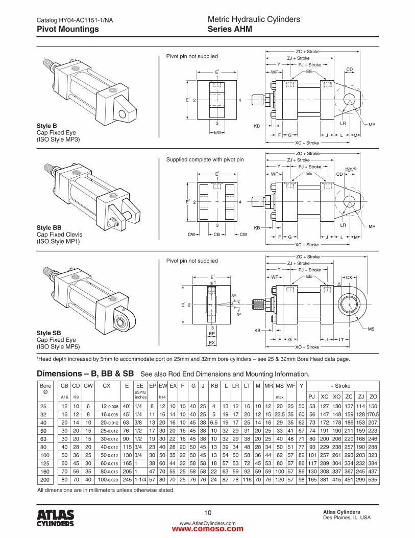
CB CD CW CX E EE EP EW EX F G J KB L LR LT M MR MS WF Y + Stroke BSP/G A16 H9 inches h14 max PJ XC XO ZC ZJ ZO
1� 10 6 1�-0.008 401 1/4 8 1� 10 10 40 �5 4 13 1� 16 10 1� �0 �5 50 53 1�7 130 137 114 150 16 1� 8 16-0.008 451 1/4 11 16 14 10 40 �5 5 19 17 �0 1� 15 ��.5 35 60 56 147 148 159 1�8 170.5 �0 14 10 �0-0.01� 63 3/8 13 �0 16 10 45 38 6.5 19 17 �5 14 16 �9 35 6� 73 17� 178 186 153 �07 30 �0 15 �5-0.01� 76 1/� 17 30 �0 16 45 38 10 3� �9 31 �0 �5 33 41 67 74 191 190 �11 159 ��3 30 20 15 30-0.01� 90 1/� 19 30 �� 16 45 38 10 3� �9 38 �0 �5 40 48 71 80 �00 �06 ��0 168 �46 40 �8 �0 40-0.01� 115 3/4 �3 40 �8 �0 50 45 13 39 34 48 �8 34 50 51 77 93 ��9 �38 �57 190 �88 50 36 �5 50-0.01� 130 3/4 30 50 35 �� 50 45 13 54 50 58 36 44 6� 57 8� 101 �57 �61 �93 �03 3�3 60 45 30 60-0.015 165 1 38 60 44 �� 58 58 18 57 53 7� 45 53 80 57 86 117 �89 304 334 �3� 384 70 56 35 80-0.015 �05 1 47 70 55 �5 58 58 �� 63 59 9� 59 59 100 57 86 130 308 337 367 �45 437 80 70 40 100-0.0�0 �45 1-1/4 57 80 70 �5 76 76 �4 8� 78 116 70 76 1�0 57 98 165 381 415 451 �99 535
1Head depth increased by 5mm to accommodate port on �5mm and 3�mm bore cylinders – see �5 & 3�mm Bore Head data page.
All dimensions are in millimeters unless otherwise stated.
Style B Cap Fixed Eye (ISO Style MP3)
Style BB Cap Fixed Clevis (ISO Style MP1)
Dimensions – B, BB & SB See also Rod End Dimensions and Mounting Information.
Pivot pin not supplied
Supplied complete with pivot pin
Pivot pin not supplied
Style SB Cap Fixed Eye (ISO Style MP5)
�5 3� 40 50 63 80 100 1�5 160 �00
Bore Ø
Pivot Mountings
www.comoso.com
Metric Hydraulic CylindersSeries AHM
Catalog HY04-AC1151-1/NA
11 Atlas CylindersDes Plaines, IL USA
www.AtlasCylinders.com
KBG J
J1
PJ + StrokeY
4 2
3
WF EE
JZB + StrokeJZJ1 + Stroke
ZJ + Stroke
XJ + Stroke
F
R 3mm
1
3
TDE1
TCTL TL
KB
XG
G J
JPJ + StrokeY
4 2
WF EE
JZB + Stroke
ZJ + Stroke
F
R 3mm
1
3
TDE1
G1
TCTL TL
W
KBG J
BD
PJ + StrokeY
4 2
WFEE
ZB + Stroke
ZJ + Stroke
XI2
F
R 3mm1
3
TDE1TY
TMTL TL
E1
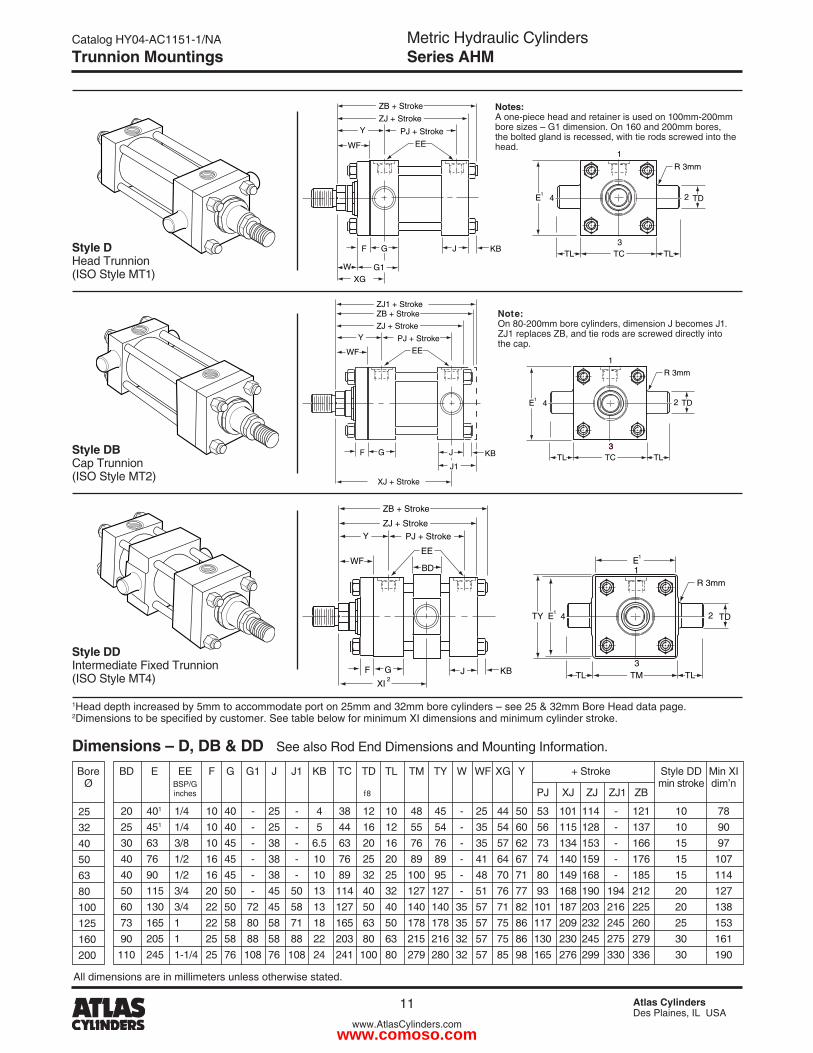
All dimensions are in millimeters unless otherwise stated.
1Head depth increased by 5mm to accommodate port on �5mm and 3�mm bore cylinders – see �5 & 3�mm Bore Head data page. �Dimensions to be specified by customer. See table below for minimum XI dimensions and minimum cylinder stroke.
Dimensions – D, DB & DD See also Rod End Dimensions and Mounting Information.
Note: On 80-�00mm bore cylinders, dimension J becomes J1. ZJ1 replaces ZB, and tie rods are screwed directly into the cap.
Style D Head Trunnion (ISO Style MT1)
Style DB Cap Trunnion (ISO Style MT�)
Style DD Intermediate Fixed Trunnion (ISO Style MT4)
Notes: A one-piece head and retainer is used on 100mm-�00mm bore sizes – G1 dimension. On 160 and �00mm bores, the bolted gland is recessed, with tie rods screwed into the head.
�5 3� 40 50 63 80 100 1�5 160 �00
Bore Ø
BD E EE F G G1 J J1 KB TC TD TL TM TY W WF XG Y + Stroke Style DD Min XI BSP/G min stroke dim’n inches f8 PJ XJ ZJ ZJ1 ZB �0 401 1/4 10 40 - �5 - 4 38 1� 10 48 45 - �5 44 50 53 101 114 - 1�1 10 78 �5 451 1/4 10 40 - �5 - 5 44 16 1� 55 54 - 35 54 60 56 115 1�8 - 137 10 90 30 63 3/8 10 45 - 38 - 6.5 63 �0 16 76 76 - 35 57 6� 73 134 153 - 166 15 97 40 76 1/� 16 45 - 38 - 10 76 �5 �0 89 89 - 41 64 67 74 140 159 - 176 15 107 40 90 1/� 16 45 - 38 - 10 89 3� �5 100 95 - 48 70 71 80 149 168 - 185 15 114 50 115 3/4 �0 50 - 45 50 13 114 40 3� 1�7 1�7 - 51 76 77 93 168 190 194 �1� �0 1�7 60 130 3/4 �� 50 7� 45 58 13 1�7 50 40 140 140 35 57 71 8� 101 187 �03 �16 ��5 �0 138 73 165 1 �� 58 80 58 71 18 165 63 50 178 178 35 57 75 86 117 �09 �3� �45 �60 �5 153 90 �05 1 �5 58 88 58 88 �� �03 80 63 �15 �16 3� 57 75 86 130 �30 �45 �75 �79 30 161 110 �45 1-1/4 �5 76 108 76 108 �4 �41 100 80 �79 �80 3� 57 85 98 165 �76 �99 330 336 30 190
Trunnion Mountings
www.comoso.com
Metric Hydraulic CylindersSeries AHM
Catalog HY04-AC1151-1/NA
1� Atlas CylindersDes Plaines, IL USA
www.AtlasCylinders.com
SW
KB
SW
XS
G F
LV + Stroke
JSV + Stroke
Y
WFEE
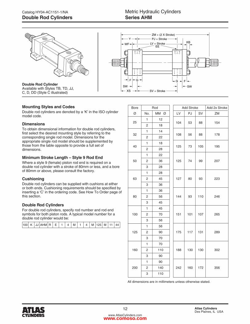
ZM + (2 X Stroke)PJ + Stroke
F G
Bore Rod Add Stroke Add �x Stroke
Ø No. MM Ø LV PJ SV ZM
�5
1 1� 104 53 88 154
� 18
3�
1 14 108 56 88 178
� ��
40
1 18 1�5 73 105 195
� �8
1 ��
50 � 36 1�5 74 99 �07
3 �8
1 �8
63 � 45 1�7 80 93 ��3
3 36
1 36
80 � 56 144 93 110 �46
3 45
1 45
100 � 70 151 101 107 �65
3 56
1 56
1�5 � 90 175 117 131 �89
3 70
1 70
160 � 110 188 130 130 30�
3 90
1 90
�00 � 140 �4� 160 17� 356
3 110
All dimensions are in millimeters unless otherwise stated.
Double Rod Cylinder Available with Styles TB, TD, JJ, C, D, DD (Style C illustrated)
Mounting Styles and CodesDouble rod cylinders are denoted by a ‘K’ in the ISO cylinder model code.
DimensionsTo obtain dimensional information for double rod cylinders, first select the desired mounting style by referring to the corresponding single rod model. Dimensions for the appropriate single rod model should be supplemented by those from the table opposite to provide a full set of dimensions.
Minimum Stroke Length – Style 9 Rod EndWhere a style 9 (female) piston rod end is required on a double rod cylinder with a stroke of 80mm or less, and a bore of 80mm or above, please consult the factory.
CushioningDouble rod cylinders can be supplied with cushions at either or both ends. Cushioning requirements should be specified by inserting a ‘C’ in the ordering code. See How To Order page of this section.
Double Rod CylindersFor double rod cylinders, specify rod number and rod end symbols for both piston rods. A typical model number for a double rod cylinder would be:
100 K JJ AHM R E 1 4 M 1 4 M 1�5 M 11 44
Double Rod Cylinders
www.comoso.com
Metric Hydraulic CylindersSeries AHM
Catalog HY04-AC1151-1/NA
13 Atlas CylindersDes Plaines, IL USA
www.AtlasCylinders.com
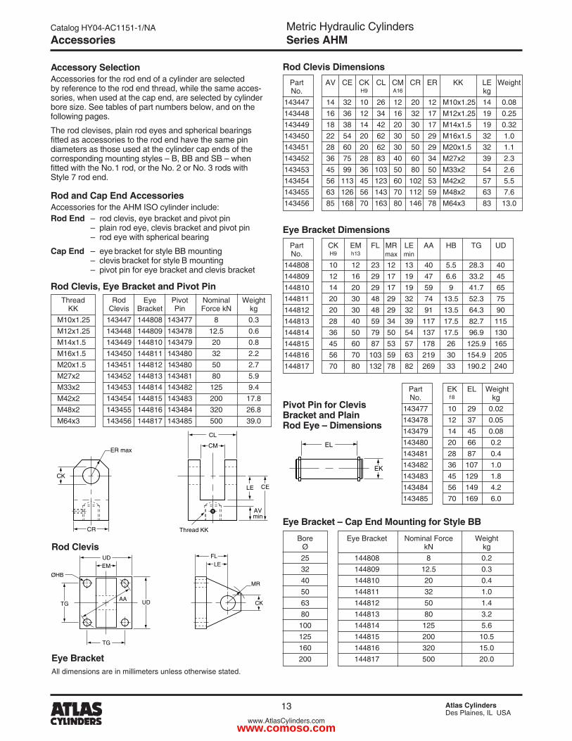
Thread Rod Eye Pivot Nominal Weight KK Clevis Bracket Pin Force kN kg M10x1.�5 143447 144808 143477 8 0.3 M1�x1.�5 143448 144809 143478 1�.5 0.6 M14x1.5 143449 144810 143479 �0 0.8 M16x1.5 143450 144811 143480 3� �.� M�0x1.5 143451 14481� 143480 50 �.7 M�7x� 14345� 144813 143481 80 5.9 M33x� 143453 144814 14348� 1�5 9.4 M4�x� 143454 144815 143483 �00 17.8 M48x� 143455 144816 143484 3�0 �6.8 M64x3 143456 144817 143485 500 39.0
Accessory SelectionAccessories for the rod end of a cylinder are selected by reference to the rod end thread, while the same acces-sories, when used at the cap end, are selected by cylinder bore size. See tables of part numbers below, and on the following pages.
The rod clevises, plain rod eyes and spherical bearings fitted as accessories to the rod end have the same pin diameters as those used at the cylinder cap ends of the corresponding mounting styles – B, BB and SB – when fitted with the No.1 rod, or the No. � or No. 3 rods with Style 7 rod end.
Rod and Cap End AccessoriesAccessories for the AHM ISO cylinder include:Rod End – rod clevis, eye bracket and pivot pin – plain rod eye, clevis bracket and pivot pin – rod eye with spherical bearing
Cap End – eye bracket for style BB mounting – clevis bracket for style B mounting – pivot pin for eye bracket and clevis bracket
Rod Clevis Dimensions
Eye Bracket Dimensions
Eye Bracket – Cap End Mounting for Style BB
Rod Clevis
All dimensions are in millimeters unless otherwise stated.
Eye Bracket
Pivot Pin for Clevis Bracket and Plain Rod Eye – Dimensions
TG
UDEM LE
FL
UD CK
MR
TGAA
ØHB
EL
EK
Rod Clevis, Eye Bracket and Pivot Pin
Part AV CE CK CL CM CR ER KK LE Weight No. H9 A16 kg 143447 14 3� 10 �6 1� �0 1� M10x1.�5 14 0.08 143448 16 36 1� 34 16 3� 17 M1�x1.�5 19 0.�5 143449 18 38 14 4� �0 30 17 M14x1.5 19 0.3� 143450 �� 54 �0 6� 30 50 �9 M16x1.5 3� 1.0 143451 �8 60 �0 6� 30 50 �9 M�0x1.5 3� 1.1 14345� 36 75 �8 83 40 60 34 M�7x� 39 �.3 143453 45 99 36 103 50 80 50 M33x� 54 �.6 143454 56 113 45 1�3 60 10� 53 M4�x� 57 5.5 143455 63 1�6 56 143 70 11� 59 M48x� 63 7.6 143456 85 168 70 163 80 146 78 M64x3 83 13.0
Part CK EM FL MR LE AA HB TG UD No. H9 h13 max min
144808 10 1� �3 1� 13 40 5.5 �8.3 40 144809 1� 16 �9 17 19 47 6.6 33.� 45 144810 14 �0 �9 17 19 59 9 41.7 65 144811 �0 30 48 �9 3� 74 13.5 5�.3 75 14481� �0 30 48 �9 3� 91 13.5 64.3 90 144813 �8 40 59 34 39 117 17.5 8�.7 115 144814 36 50 79 50 54 137 17.5 96.9 130 144815 45 60 87 53 57 178 �6 1�5.9 165 144816 56 70 103 59 63 �19 30 154.9 �05 144817 70 80 13� 78 8� �69 33 190.� �40
Part EK EL Weight No. f8 kg 143477 10 �9 0.0� 143478 1� 37 0.05 143479 14 45 0.08 143480 �0 66 0.� 143481 �8 87 0.4 14348� 36 107 1.0 143483 45 1�9 1.8 143484 56 149 4.� 143485 70 169 6.0
Bore Eye Bracket Nominal Force Weight Ø kN kg �5 144808 8 0.� 3� 144809 1�.5 0.3 40 144810 �0 0.4 50 144811 3� 1.0 63 14481� 50 1.4 80 144813 80 3.� 100 144814 1�5 5.6 1�5 144815 �00 10.5 160 144816 3�0 15.0 �00 144817 500 �0.0
AVmin
Thread KK
ER max
CK
LE
CL
CM
CE
CR
Accessories
www.comoso.com
Metric Hydraulic CylindersSeries AHM
Catalog HY04-AC1151-1/NA
14 Atlas CylindersDes Plaines, IL USA
www.AtlasCylinders.com
LE
FL
TB UH CK
MR
ØHB
UR
RC
CMCW CW
CB
EMh13
CA
LE
AWmin
CK
CD CD
KKThread
ER max
EL
EK
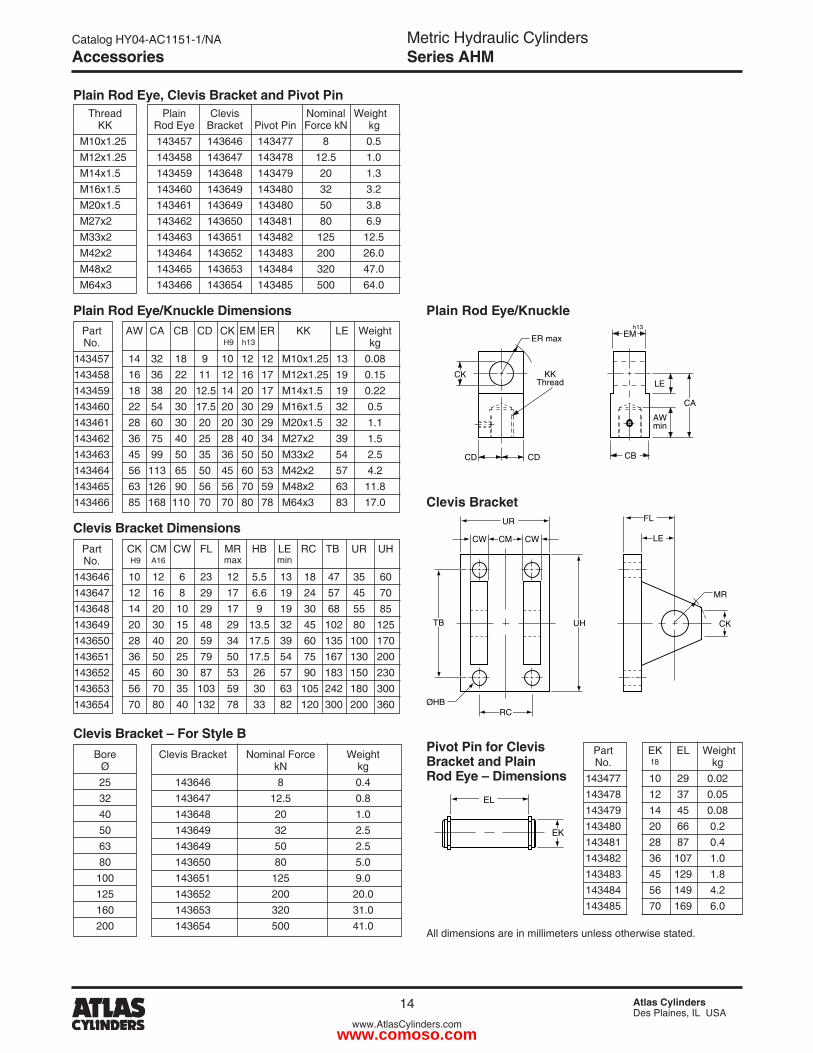
Bore Clevis Bracket Nominal Force Weight Ø kN kg �5 143646 8 0.4 3� 143647 1�.5 0.8 40 143648 �0 1.0 50 143649 3� �.5 63 143649 50 �.5 80 143650 80 5.0 100 143651 1�5 9.0 1�5 14365� �00 �0.0 160 143653 3�0 31.0 �00 143654 500 41.0
Part AW CA CB CD CK EM ER KK LE Weight No. H9 h13 kg 143457 14 3� 18 9 10 1� 1� M10x1.�5 13 0.08 143458 16 36 �� 11 1� 16 17 M1�x1.�5 19 0.15 143459 18 38 �0 1�.5 14 �0 17 M14x1.5 19 0.�� 143460 �� 54 30 17.5 �0 30 �9 M16x1.5 3� 0.5 143461 �8 60 30 �0 �0 30 �9 M�0x1.5 3� 1.1 14346� 36 75 40 �5 �8 40 34 M�7x� 39 1.5 143463 45 99 50 35 36 50 50 M33x� 54 �.5 143464 56 113 65 50 45 60 53 M4�x� 57 4.� 143465 63 1�6 90 56 56 70 59 M48x� 63 11.8 143466 85 168 110 70 70 80 78 M64x3 83 17.0
Plain Rod Eye, Clevis Bracket and Pivot Pin
Plain Rod Eye/Knuckle Dimensions
Clevis Bracket Dimensions
Clevis Bracket – For Style B
Plain Rod Eye/Knuckle
Pivot Pin for Clevis Bracket and Plain Rod Eye – Dimensions
All dimensions are in millimeters unless otherwise stated.
Clevis Bracket
Thread Plain Clevis Nominal Weight KK Rod Eye Bracket Pivot Pin Force kN kg M10x1.�5 143457 143646 143477 8 0.5 M1�x1.�5 143458 143647 143478 1�.5 1.0 M14x1.5 143459 143648 143479 �0 1.3 M16x1.5 143460 143649 143480 3� 3.� M�0x1.5 143461 143649 143480 50 3.8 M�7x� 14346� 143650 143481 80 6.9 M33x� 143463 143651 14348� 1�5 1�.5 M4�x� 143464 14365� 143483 �00 �6.0 M48x� 143465 143653 143484 3�0 47.0 M64x3 143466 143654 143485 500 64.0
Part CK CM CW FL MR HB LE RC TB UR UH No. H9 A16 max min
143646 10 1� 6 �3 1� 5.5 13 18 47 35 60 143647 1� 16 8 �9 17 6.6 19 �4 57 45 70 143648 14 �0 10 �9 17 9 19 30 68 55 85 143649 �0 30 15 48 �9 13.5 3� 45 10� 80 1�5 143650 �8 40 �0 59 34 17.5 39 60 135 100 170 143651 36 50 �5 79 50 17.5 54 75 167 130 �00 14365� 45 60 30 87 53 �6 57 90 183 150 �30 143653 56 70 35 103 59 30 63 105 �4� 180 300 143654 70 80 40 13� 78 33 8� 1�0 300 �00 360
Part EK EL Weight No. f8 kg 143477 10 �9 0.0� 143478 1� 37 0.05 143479 14 45 0.08 143480 �0 66 0.� 143481 �8 87 0.4 14348� 36 107 1.0 143483 45 1�9 1.8 143484 56 149 4.� 143485 70 169 6.0
Accessories
www.comoso.com
Metric Hydraulic CylindersSeries AHM
Catalog HY04-AC1151-1/NA
15 Atlas CylindersDes Plaines, IL USA
www.AtlasCylinders.com
TA
FM
KC
GL
LO
CO
FO
SR
CG
UK
RE
CF
LJLG
UJ
CP
HBØ
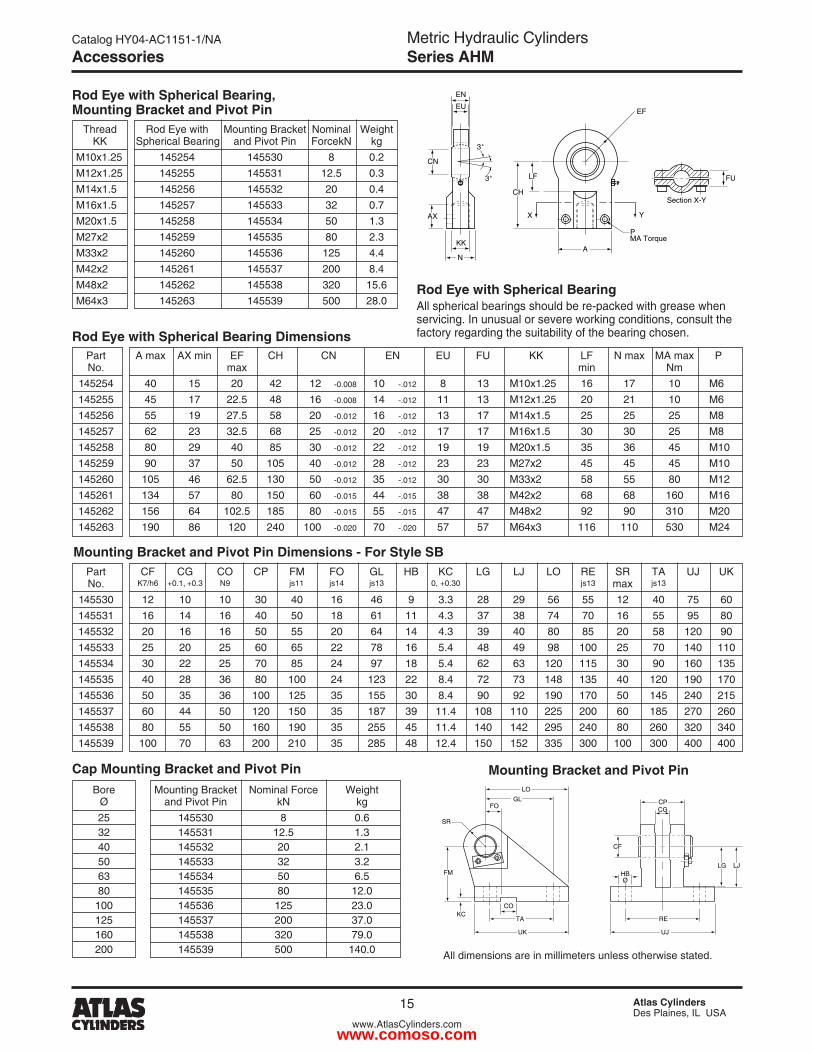
Bore Mounting Bracket Nominal Force Weight Ø and Pivot Pin kN kg �5 145530 8 0.6 3� 145531 1�.5 1.3 40 14553� �0 �.1 50 145533 3� 3.� 63 145534 50 6.5 80 145535 80 1�.0 100 145536 1�5 �3.0 1�5 145537 �00 37.0 160 145538 3�0 79.0 �00 145539 500 140.0
Cap Mounting Bracket and Pivot Pin
Rod Eye with Spherical Bearing, Mounting Bracket and Pivot Pin
Rod Eye with Spherical Bearing Dimensions
Rod Eye with Spherical BearingAll spherical bearings should be re-packed with grease when servicing. In unusual or severe working conditions, consult the factory regarding the suitability of the bearing chosen.
CH
LF
X Y
Section X-Y
EF
PMA Torque
3˚
3˚
EU
EN
AX
AN
KK
FU
CN
All dimensions are in millimeters unless otherwise stated.
Thread Rod Eye with Mounting Bracket Nominal Weight KK Spherical Bearing and Pivot Pin Force kN kg M10x1.�5 145�54 145530 8 0.� M1�x1.�5 145�55 145531 1�.5 0.3 M14x1.5 145�56 14553� �0 0.4 M16x1.5 145�57 145533 3� 0.7 M�0x1.5 145�58 145534 50 1.3 M�7x� 145�59 145535 80 �.3 M33x� 145�60 145536 1�5 4.4 M4�x� 145�61 145537 �00 8.4 M48x� 145�6� 145538 3�0 15.6 M64x3 145�63 145539 500 �8.0
Part A max AX min EF CH CN EN EU FU KK LF N max MA max P No. max min Nm 145�54 40 15 �0 4� 1� -0.008 10 -.01� 8 13 M10x1.�5 16 17 10 M6 145�55 45 17 ��.5 48 16 -0.008 14 -.01� 11 13 M1�x1.�5 �0 �1 10 M6 145�56 55 19 �7.5 58 �0 -0.01� 16 -.01� 13 17 M14x1.5 �5 �5 �5 M8 145�57 6� �3 3�.5 68 �5 -0.01� �0 -.01� 17 17 M16x1.5 30 30 �5 M8 145�58 80 �9 40 85 30 -0.01� �� -.01� 19 19 M�0x1.5 35 36 45 M10 145�59 90 37 50 105 40 -0.01� �8 -.01� �3 �3 M�7x� 45 45 45 M10 145�60 105 46 6�.5 130 50 -0.01� 35 -.01� 30 30 M33x� 58 55 80 M1� 145�61 134 57 80 150 60 -0.015 44 -.015 38 38 M4�x� 68 68 160 M16 145�6� 156 64 10�.5 185 80 -0.015 55 -.015 47 47 M48x� 9� 90 310 M�0 145�63 190 86 1�0 �40 100 -0.0�0 70 -.0�0 57 57 M64x3 116 110 530 M�4
Mounting Bracket and Pivot Pin Dimensions - For Style SB Part CF CG CO CP FM FO GL HB KC LG LJ LO RE SR TA UJ UK No. K7/h6 +0.1, +0.3 N9 js11 js14 js13 0, +0.30 js13 max js13
145530 1� 10 10 30 40 16 46 9 3.3 �8 �9 56 55 1� 40 75 60 145531 16 14 16 40 50 18 61 11 4.3 37 38 74 70 16 55 95 80 14553� �0 16 16 50 55 �0 64 14 4.3 39 40 80 85 �0 58 1�0 90 145533 �5 �0 �5 60 65 �� 78 16 5.4 48 49 98 100 �5 70 140 110 145534 30 �� �5 70 85 �4 97 18 5.4 6� 63 1�0 115 30 90 160 135 145535 40 �8 36 80 100 �4 1�3 �� 8.4 7� 73 148 135 40 1�0 190 170 145536 50 35 36 100 1�5 35 155 30 8.4 90 9� 190 170 50 145 �40 �15 145537 60 44 50 1�0 150 35 187 39 11.4 108 110 ��5 �00 60 185 �70 �60 145538 80 55 50 160 190 35 �55 45 11.4 140 14� �95 �40 80 �60 3�0 340 145539 100 70 63 �00 �10 35 �85 48 1�.4 150 15� 335 300 100 300 400 400
Mounting Bracket and Pivot Pin
Accessories
www.comoso.com
Metric Hydraulic CylindersSeries AHM
Catalog HY04-AC1151-1/NA
16 Atlas CylindersDes Plaines, IL USA
www.AtlasCylinders.com
How to Order ISO CylindersData Required On All Cylinder Orders
When ordering Series AHM cylinders, be sure to specify each of the following requirements:
(NOTE: – Duplicate cylinders can be ordered by giving the SERIAL NUMBER from the nameplate of the original cylinder. Factory records supply a quick, positive identification.)
a) Bore Size
b) Mounting Style Specify your choice of mounting style – as shown and dimensioned in this catalog. If double rod is required, specify “with double rod.”
c) Series Designation (“AHM”)
d) Length of Stroke
e) Piston Rod Diameter Call out rod diameter or rod code number. In Series AHM cylinders, standard rod diameters (Code No. 1) will be furnished if not otherwise specified, unless length of stroke makes the application questionable.
f) Piston Rod End Thread Style Call out thread style number or specify dimensions. Thread style number 4 will be furnished if not otherwise specified.
ADDITIONAL DATA is required on orders for cylinders with special modifications. For further information, consult factory.
g) Cushions (if required) Specify “Cushion-head end,” “Cushion-cap end” or “Cushion-both ends” as required. If cylinder is to have a double rod and only one cushion is required, be sure to specify clearly which end of the cylinder is to be cushioned.
h) Piston Atlas Cylinders B style pistons are standard. Fluorocarbon also available.
i) Ports BSP (ISO ��8) are standard.
j) Fluid Medium Series AHM hydraulic cylinders are equipped with seals for use with hydraulic oil. If other than hydraulic oil will be used, consult factory.
Service PolicyOn cylinders returned to the factory for repairs, it is standard policy for Atlas Cylinders to make such part replacements as will put the cylinder in as good as new condition. Should the condition of the returned cylinder be such that expenses for repair would exceed the costs of a new one, you will be notified.
Address all correspondence to Service Department at your nearest regional plant listed in the pages of this catalog.
Model Numbers
www.comoso.com
Metric Hydraulic CylindersSeries AHM
Catalog HY04-AC1151-1/NA
17 Atlas CylindersDes Plaines, IL USA
www.AtlasCylinders.com
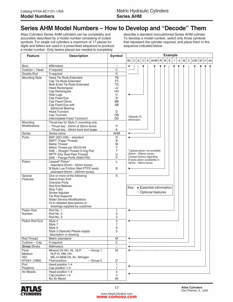
Series AHM Model Numbers – How to Develop and “Decode” ThemAtlas Cylinders Series AHM cylinders can be completely and accurately described by a model number consisting of coded symbols. For single rod cylinders a maximum of 17 places for digits and letters are used in a prescribed sequence to produce a model number. Only twelve places are needed to completely
describe a standard noncushioned Series AHM cylinder. To develop a model number, select only those symbols that represent the cylinder required, and place them in the sequence indicated below.
Model Numbers
Feature Description Symbol 80 C K C K AHM R B S 1 4 M C �30 M 11 44
Example
Key: Essential information Optional features
Bore Millimeters – Cushion – Head If required C Double Rod If required K Mounting Style Head Tie Rods Extended TB Cap Tie Rods Extended TC Both Ends Tie Rods Extended TD Head Rectangular JJ Cap Rectangular HH Side Lugs C Cap Fixed Eye B Cap Fixed Clevis BB Cap Fixed Eye with SB Spherical Bearing Head Trunnion D Cap Trunnion DB Intermediate Fixed Trunnion† DD Mounting Thrust key for Style C mounting only Modifications – Thrust key - �5mm & 3�mm bores P – Thrust key - 40mm bore and larger K Series Series name AHM Ports BSP (ISO ��8) – standard R BSPT (Taper Thread) B Metric Thread M Metric Thread per ISO 6149 Y SAE – Straight Thread O-ring Port T NPTF (Dry Seal Pipe Thread) U SAE – Flange Ports (3000 PSI) P Piston Lipseal® Piston* L (standard �5mm - 40mm bores) B-Style Low Friction filled PTFE seals B (standard 50mm - �00mm bores) Special One or more of the following: S Features Gland Drain Port Oversize Ports Rod End Bellows Stop Tube Stroke Adjuster Tie Rod Supports Water Service Modifications Or to detailed descriptions or drawings supplied by customer Piston Rod Rod No. 1 1 Number Rod No. � � Rod No. 3 3 Piston Rod End Style 4 4 Style 7 7 Style 9 9 Style 3 (Special) Please supply 3 description or drawing Rod Thread Metric (standard) M Cushion – Cap If required C Gross Stroke Millimeters – Fluid Mineral Oil HH, HL, HLP, – Group 1 M Medium HLP-D, HM, HV, ISO MIL-H-5606 Oil, Air, Nitrogen 6743/4 (198�) Fluorocarbon – Group 5 D Port Head position 1-4 1 Positions Cap position 1-4 1 Air Bleeds Head position 1-4 4 Cap position 1-4 4 No Air Bleed 00
†Specify XI dimension.
*Lipseal piston not available 50mm - �00mm bores. Contact factory regarding B-style piston availability in �5mm - 40mm bores.
www.comoso.com
18 Atlas CylindersDes Plaines, IL USA
www.AtlasCylinders.com
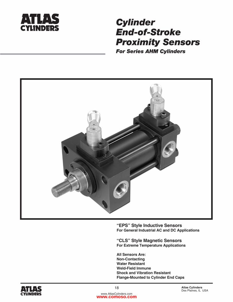
“EPS” Style Inductive SensorsFor General Industrial AC and DC Applications
“CLS” Style Magnetic SensorsFor Extreme Temperature Applications
All Sensors Are:Non-ContactingWater ResistantWeld-Field ImmuneShock and Vibration ResistantFlange-Mounted to Cylinder End Caps
CylinderEnd-of-StrokeProximity SensorsFor Series AHM Cylinders
www.comoso.com
Metric Hydraulic CylindersSeries AHM
Catalog HY04-AC1151-1/NA
19 Atlas CylindersDes Plaines, IL USA
www.AtlasCylinders.com
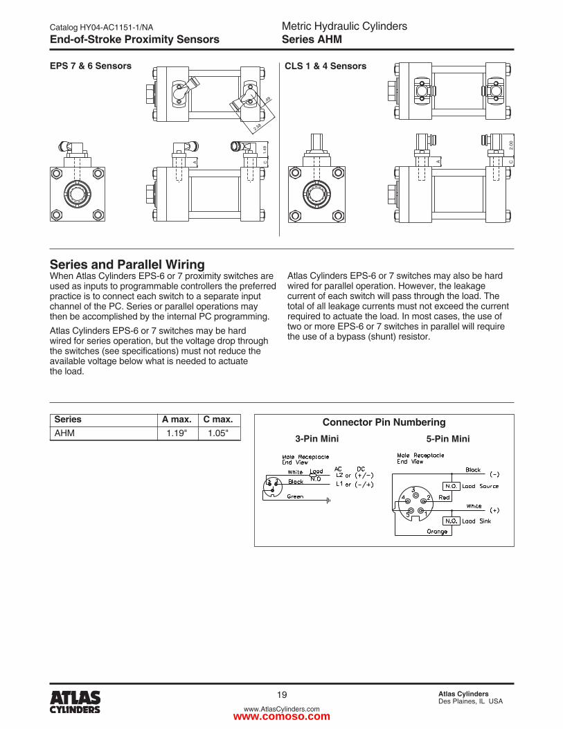
Series A max. C max.AHM 1.19" 1.05"
2.58
1.49
.49
CA
2.00
CA
EPS 7 & 6 Sensors CLS 1 & 4 Sensors
Series and Parallel WiringWhen Atlas Cylinders EPS-6 or 7 proximity switches are used as inputs to programmable controllers the preferred practice is to connect each switch to a separate input channel of the PC. Series or parallel operations may then be accomplished by the internal PC programming.Atlas Cylinders EPS-6 or 7 switches may be hard wired for series operation, but the voltage drop through the switches (see specifications) must not reduce the available voltage below what is needed to actuate the load.
Atlas Cylinders EPS-6 or 7 switches may also be hard wired for parallel operation. However, the leakage current of each switch will pass through the load. The total of all leakage currents must not exceed the current required to actuate the load. In most cases, the use of two or more EPS-6 or 7 switches in parallel will require the use of a bypass (shunt) resistor.
3-Pin Mini 5-Pin Mini
Connector Pin Numbering
End-of-Stroke Proximity Sensors
www.comoso.com
Metric Hydraulic CylindersSeries AHM
Catalog HY04-AC1151-1/NA
�0 Atlas CylindersDes Plaines, IL USA
www.AtlasCylinders.com
End-of-Stroke Proximity Sensors
4-SLC1-SLC6-SPE:elytS
Code Designator: BFD
Description:
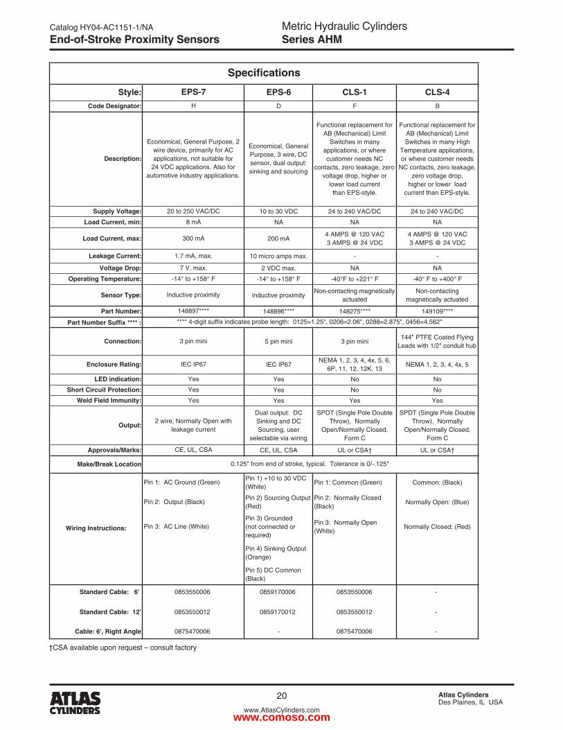
Economical, General Purpose, 3 wire, DC sensor, dual output: sinking and sourcing
Functional replacement for AB (Mechanical) Limit
Switches in many applications, or where customer needs NC
contacts, zero leakage, zero voltage drop, higher or
lower load currentthan EPS-style.
Functional replacement for AB (Mechanical) Limit Switches in many High
Temperature applications, or where customer needs
NC contacts, zero leakage, zero voltage drop,
higher or lower load current than EPS-style.
Supply Voltage: 10 to 30 VDC 24 to 240 VAC/DC 24 to 240 VAC/DC
Load Current, min: ANANAN
Load Current, max: 200 mA4 AMPS @ 120 VAC3 AMPS @ 24 VDC
4 AMPS @ 120 VAC3 AMPS @ 24 VDC
Leakage Current: --.xam spma orcim 01
Voltage Drop: ANAN.xam CDV 2
Operating Temperature: -14° to +158° F -40°F to +221° F -40° F to +400° F
Sensor Type: Inductive proximityNon-contacting magnetically
actuatedNon-contacting
magnetically actuated
Part Number: 148896**** 148275**** 149109****
Part Number Suffix **** :
Connection: 5 pin mini 3 pin mini144" PTFE Coated Flying
Leads with 1/2" conduit hub
Enclosure Rating: IEC IP67NEMA 1, 2, 3, 4, 4x, 5, 6,
6P, 11, 12, 12K, 13NEMA 1, 2, 3, 4, 4x, 5
LED indication: oNoNseY
Short Circuit Protection: oN oNseY
Weld Field Immunity: seYseYseY
Output:
Dual output: DC Sinking and DC Sourcing, user
selectable via wiring
SPDT (Single Pole Double Throw), Normally
Open/Normally Closed,Form C
SPDT (Single Pole Double Throw), Normally
Open/Normally Closed,Form C
Approvals/Marks: CE, UL, CSA UL or CSA† UL or CSA†
Make/Break Location
Pin 1) +10 to 30 VDC (White)
Pin 1: Common (Green) Common: (Black)
Pin 2) Sourcing Output (Red)
Pin 2: Normally Closed (Black)
Normally Open: (Blue)
Pin 3) Grounded(not connected or required)
Pin 3: Normally Open (White)
Normally Closed: (Red)
Pin 4) Sinking Output (Orange)
Pin 5) DC Common (Black)
Standard Cable: 6' 0859170006 0853550006 -
Standard Cable: 12' 0859170012 0853550012 -
Cable: 6', Right Angle - 0875470006 -
0853550006
0853550012
0875470006
Yes
2 wire, Normally Open with leakage current
CE, UL, CSA
Pin 1: AC Ground (Green)
0.125" from end of stroke, typical. Tolerance is 0/-.125"
3 pin mini
IEC IP67
Yes
Yes
7 V, max.
-14° to +158° F
Inductive proximity
148897****
Economical, General Purpose, 2 wire device, primarily for AC applications, not suitable for
24 VDC applications. Also for automotive industry applications.
**** 4-digit suffix indicates probe length: 0125=1.25", 0206=2.06", 0288=2.875", 0456=4.562"
Specifications
EPS-7
H
20 to 250 VAC/DC
8 mA
300 mA
1.7 mA, max.
Wiring Instructions:
Pin 2: Output (Black)
Pin 3: AC Line (White)
†CSA available upon request – consult factory
www.comoso.com
Metric Hydraulic CylindersSeries AHM
Catalog HY04-AC1151-1/NA
�1 Atlas CylindersDes Plaines, IL USA
www.AtlasCylinders.com
End-of-Stroke Proximity Sensors
2
1
4
3
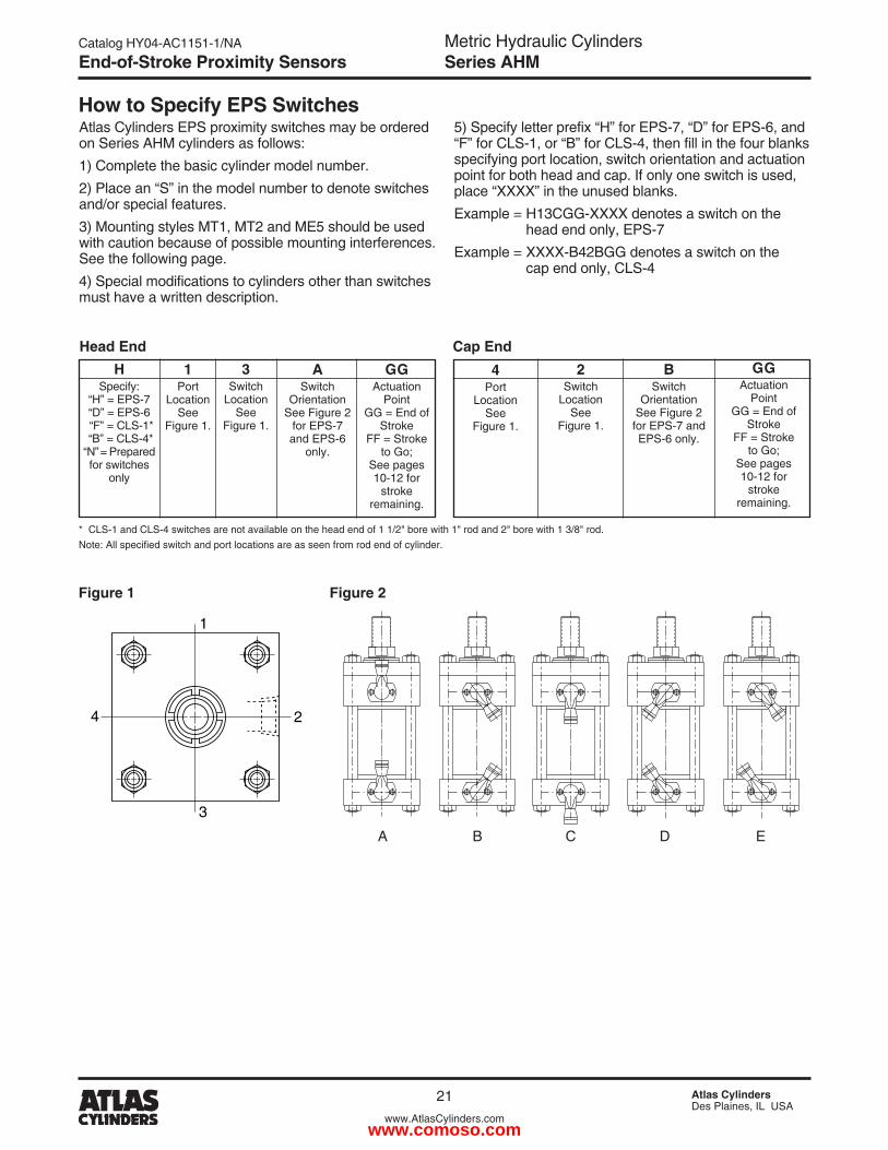
Atlas Cylinders EPS proximity switches may be ordered on Series AHM cylinders as follows:1) Complete the basic cylinder model number.�) Place an “S” in the model number to denote switches and/or special features.3) Mounting styles MT1, MT� and ME5 should be used with caution because of possible mounting interferences. See the following page.4) Special modifications to cylinders other than switches must have a written description.
5) Specify letter prefix “H” for EPS-7, “D” for EPS-6, and “F” for CLS-1, or “B” for CLS-4, then fill in the four blanks specifying port location, switch orientation and actuation point for both head and cap. If only one switch is used, place “XXXX” in the unused blanks.Example = H13CGG-XXXX denotes a switch on the head end only, EPS-7Example = XXXX-B4�BGG denotes a switch on the cap end only, CLS-4
Head EndH
Specify:“H” = EPS-7“D” = EPS-6
“F” = CLS-1* “B” = CLS-4*“N” = Prepared for switches
only
1Port
LocationSee
Figure 1.
3Switch
LocationSee
Figure 1.
ASwitch
OrientationSee Figure �
for EPS-7 and EPS-6
only.
GGActuation
Point GG = End of
StrokeFF = Stroke
to Go; See pages 10-1� for
stroke remaining.
Cap End4
PortLocation
SeeFigure 1.
2Switch
LocationSee
Figure 1.
GGActuation
Point GG = End of
StrokeFF = Stroke
to Go; See pages 10-1� for
stroke remaining.
BSwitch
OrientationSee Figure �for EPS-7 and EPS-6 only.
* CLS-1 and CLS-4 switches are not available on the head end of 1 1/�" bore with 1" rod and �" bore with 1 3/8" rod.Note: All specified switch and port locations are as seen from rod end of cylinder.
Figure 1 Figure 2
A B C D E
How to Specify EPS Switches
www.comoso.com
Metric Hydraulic CylindersSeries AHM
Catalog HY04-AC1151-1/NA
�� Atlas CylindersDes Plaines, IL USA
www.AtlasCylinders.com
End-of-Stroke Proximity Sensors
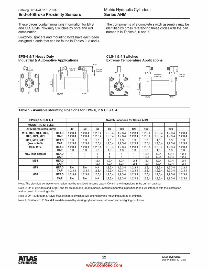
Table 1 - Available Mounting Positions for EPS- 6, 7 & CLS 1, 4
These pages contain mounting information for EPS and CLS Style Proximity Switches by bore and rod combination.Switches, spacers and mounting bolts have each been assigned a code that can be found in Tables �, 3 and 4.
SPACERHEIGHT
1.49
HEAD CAP
2
3
4
1
SPACERHEIGHT
EPS-6 & 7 Heavy Duty Industrial & Automotive Applications
EPS 6,7 & CLS 1, 4 Switch Locations for Series AHM
MOUNTING STYLES AHM bores sizes (mm): 40 50 63 80 100 125 160 – 200 – MT4, MX0, MX1, MX2, HEAD 1,�,3,4 1,�,3,4 1,�,3,4 1,�,3,4 1,�,3,4 1,�,3,4 1,�,3,4 1,�,3,4 1,�,3,4 1,�,3,4 MX3, MP1, MP5 CAP 1,�,3,4 1,�,3,4 1,�,3,4 1,�,3,4 1,�,3,4 1,�,3,4 1,�,3,4 1,�,3,4 1,�,3,4 1,�,3,4 MF1, ME5, MT1 HEAD 1,3 1,3 1,3 1,3 1,3 1,3 1,3 1,3 1,3 1,3 (see note 3) CAP 1,�,3,4 1,�,3,4 1,�,3,4 1,�,3,4 1,�,3,4 1,�,3,4 1,�,3,4 1,�,3,4 1,�,3,4 1,�,3,4 ME6, MT2 HEAD 1,�,3,4 1,�,3,4 1,�,3,4 1,�,3,4 1,�,3,4 1,�,3,4 1,�,3,4 1,�,3,4 1,�,3,4 1,�,3,4 CAP 1,3 1,3 1,3 1,3 1,3 1,3 1,3 1,3 1,3 1,3 MS2 (see note 2) HEAD 1 1 1 1 1 1 1,�,4 1,�,4 1,�,4 1,�,4 CAP 1 1 1 1 1 1 1,�,4 1,�,4 1,�,4 1,�,4 MS4 HEAD 1 1 1,�,4 1,�,4 1,�,4 1,�,4 1,�,4 1,�,4 1,�,4 1,�,4 CAP 1 1 1,�,4 1,�,4 1,�,4 1,�,4 1,�,4 1,�,4 1,�,4 1,�,4 MF5 HEAD NA NA NA 1,�,3,4 1,�,3,4 1,�,3,4 1,�,3,4 1,�,3,4 1,�,3,4 1,�,3,4 CAP 1,�,3,4 1,�,3,4 1,�,3,4 1,�,3,4 1,�,3,4 1,�,3,4 1,�,3,4 1,�,3,4 1,�,3,4 1,�,3,4 MF6 HEAD 1,�,3,4 1,�,3,4 1,�,3,4 1,�,3,4 1,�,3,4 1,�,3,4 1,�,3,4 1,�,3,4 1,�,3,4 1,�,3,4 CAP NA NA NA 1,�,3,4 1,�,3,4 1,�,3,4 1,�,3,4 1,�,3,4 1,�,3,4 1,�,3,4
Note: The electrical connector orientation may be restricted in some cases. Consult the dimensions in the current catalog.
Note �: On 6" cylinders and larger, and for 160mm and �00mm bores, switches mounted in position � or 4 will interfere with the installation and removal of mounting bolts.
Note 3: On 1.5 through 5" Style ME5 cylinders, switches will extend beyond mounting surface of cylinder.
Note 4: Positions 1, �, 3 and 4 are determined by viewing cylinder from piston rod end and going clockwise.
CLS-1 & 4 Switches Extreme Temperature Applications
2.00
SPACERHEIGHT
SPACERHEIGHT
CAPHEAD
The components of a complete switch assembly may be identified by cross referencing these codes with the part numbers in Tables 5, 6 and 7.
www.comoso.com
Metric Hydraulic CylindersSeries AHM
Catalog HY04-AC1151-1/NA
�3 Atlas CylindersDes Plaines, IL USA
www.AtlasCylinders.com
End-of-Stroke Proximity Sensors
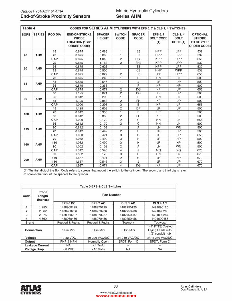
Table 5-EPS & CLS Switches Probe Code Length Part Number (inches) EPS 6 DC EPS 7 AC CLS 1 AC CLS 4 AC 1 1.�50 14889601�5 14889701�5 148�7501�5 14910901�5 2 �.06� 1488960�06 1488970�06 148�750�06 1491090�06 3 �.875 1488960�87 1488970�87 148�750�87 1491090�87 4 4.56� 1488960456 1488970456 148�750456 1491090456 Brand Pepperl & Fuchs Pepperl & Fuchs Topworx Topworx 144" PTFE Coated Connection 5 Pin Mini 3 Pin Mini 3 Pin Mini Flying Leads with 1/�" conduit hub Voltage 10-30 VDC 50-��0 VAC/DC �4-�40 VAC/DC �4 to �40 VAC/DC Output PNP & NPN Normally Open SPDT, Form C SPDT, Form C Leakage Current NA <1.7mA – – Voltage Drop <.8 VDC <10 Volts NA NA
Table 4 BORE
CODES FOR SERIES AHM CYLINDERS WITH EPS 6, 7 & CLS 1, 4 SWITCHES
SERIES ROD DIA END-OF-STROKE SPACER SWITCH SPACER EPS 6, 7 CLS 1, 4 OPTIONAL PROBE HEIGHT CODE CODE BOLT CODE BOLT STROKE LOCATION (“GG” (1) CODE (1) TO GO (“FF” ORDER CODE) ORDER CODE)
18 0.875 0.688 1 E3 HPP LPP .53� 40 AHM 28 0.875 0.688 1 F3 HPP LPP .53� CAP 0.875 1.048 � EG3 KPP UPP .656 22 0.875 1.188 � FH3 KPP UPP .53�
50 AHM 36 0.875 0.6�6 1 E3 HPP LPP .53� 28 0.875 0.500 1 C3 HNP WPP .53� CAP 0.875 0.8�9 � H3 JPP HPP .656 28 0.875 0.�49 1 D HN LN .500
63 AHM 45 0.875 0.546 1 J JP UP .500 36 0.875 0.358 1 F HP HP .500 CAP 0.875 0.671 � DG KP UP .656 36 1.1�5 0.671 � DG KP UP .500
80 AHM 56 0.81� 0.�96 1 E HN LN .500 45 1.1�5 0.858 � FH KP UP .500 CAP 1.000 0.�96 � E HP LP .656 45 1.1�5 0.608 � DF JP UP .500
100 AHM 70 0.81� 0.358 1 F HP LP .500 56 0.81� 0.858 � FH KP JP .500 CAP 1.000 0.170 � C HN LN .656 56 0.81� 0.170 � C HN LN .500
125 AHM 90 0.81� 0.109 1 A LN WN .500 70 0.81� 0.499 � H JP HP .500 CAP 1.000 0.4�1 3 G JP HP .656 70 1.06� 0.499 3 H JP HP .500
160 AHM 110 1.06� 0.499 � H JP HP .500 90 1.06� 0.109 � A LN WN .500 CAP 1.31� 0.546 4 J MQ YQ .670 90 1.56� 0.170 3 C HN LN .670
200 AHM 140 1.687 0.4�1 � G JP HP .670 110 1.687 0.546 3 J JP UP .670 CAP 1.937 0.671 4 DG KP UP .670
(1) The first digit of the Bolt Code refers to screws that mount the switch to the cylinder. The second and third digits refer to screws that mount the spacers to the cylinder.
www.comoso.com
Metric Hydraulic CylindersSeries AHM
Catalog HY04-AC1151-1/NA
�4 Atlas CylindersDes Plaines, IL USA
www.AtlasCylinders.com
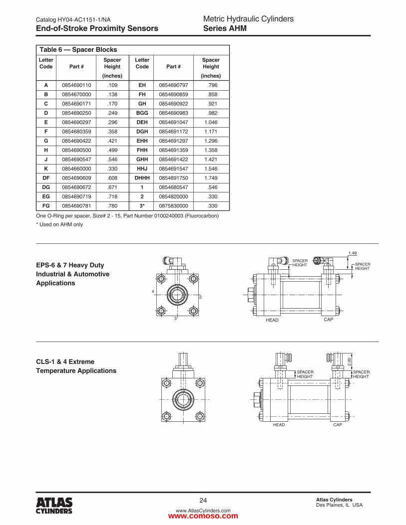
Table 6 — Spacer Blocks Letter Spacer Letter Spacer Code Part # Height Code Part # Height
(inches) (inches)
A 0854690110 .109 EH 0854690797 .796
B 0854670000 .138 FH 0854690859 .858
C 0854690171 .170 GH 08546909�� .9�1
D 0854690�50 .�49 BGG 0854690983 .98�
E 0854690�97 .�96 DEH 0854691047 1.046
F 0854680359 .358 DGH 085469117� 1.171
G 08546904�� .4�1 EHH 0854691�97 1.�96
H 0854690500 .499 FHH 0854691359 1.358
J 0854690547 .546 GHH 08546914�� 1.4�1
K 0854660000 .330 HHJ 0854691547 1.546
DF 0854690609 .608 DHHH 0854691750 1.749
DG 085469067� .671 1 0854680547 .546
EG 0854690719 .718 2 08548�0000 .330
FG 0854690781 .780 3* 0875830000 .330
One O-Ring per spacer, Size# � - 15, Part Number 0100�40003 (Fluorocarbon)
* Used on AHM only
SPACERHEIGHT
1.49
HEAD CAP
2
3
4
1
SPACERHEIGHT
EPS-6 & 7 Heavy Duty Industrial & Automotive Applications
CLS-1 & 4 Extreme Temperature Applications
2.00
SPACERHEIGHT
SPACERHEIGHT
CAPHEAD
End-of-Stroke Proximity Sensors
www.comoso.com
Metric Hydraulic CylindersSeries AHM
Catalog HY04-AC1151-1/NA
�5 Atlas CylindersDes Plaines, IL USA
www.AtlasCylinders.com
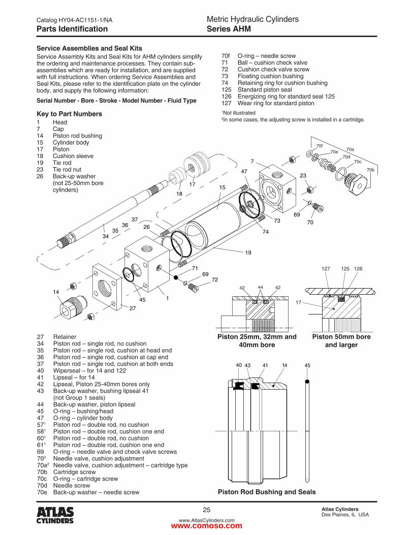
�7 Retainer 34 Piston rod – single rod, no cushion 35 Piston rod – single rod, cushion at head end 36 Piston rod – single rod, cushion at cap end 37 Piston rod – single rod, cushion at both ends 40 Wiperseal – for 14 and 1�� 41 Lipseal – for 14 4� Lipseal, Piston �5-40mm bores only 43 Back-up washer, bushing lipseal 41 (not Group 1 seals) 44 Back-up washer, piston lipseal 45 O-ring – bushing/head 47 O-ring – cylinder body 571 Piston rod – double rod, no cushion 581 Piston rod – double rod, cushion one end 601 Piston rod – double rod, no cushion 611 Piston rod – double rod, cushion one end 69 O-ring – needle valve and check valve screws 70� Needle valve, cushion adjustment 70a� Needle valve, cushion adjustment – cartridge type 70b Cartridge screw 70c O-ring – cartridge screw 70d Needle screw 70e Back-up washer – needle screw
Service Assemblies and Seal KitsService Assembly Kits and Seal Kits for AHM cylinders simplify the ordering and maintenance processes. They contain sub-assemblies which are ready for installation, and are supplied with full instructions. When ordering Service Assemblies and Seal Kits, please refer to the identification plate on the cylinder body, and supply the following information:
Serial Number - Bore - Stroke - Model Number - Fluid Type
Key to Part Numbers1 Head 7 Cap 14 Piston rod bushing 15 Cylinder body 17 Piston 18 Cushion sleeve 19 Tie rod �3 Tie rod nut �6 Back-up washer (not �5-50mm bore cylinders)
70f O-ring – needle screw 71 Ball – cushion check valve 7� Cushion check valve screw 73 Floating cushion bushing 74 Retaining ring for cushion bushing 1�5 Standard piston seal 1�6 Energizing ring for standard seal 1�5 1�7 Wear ring for standard piston1Not illustrated �In some cases, the adjusting screw is installed in a cartridge.
17
127 125 126
Piston 50mm bore and larger
Piston Rod Bushing and Seals
3435
3637
18
17
14
27
45 1
7269
71
6970
23
73
74
47
26
19
7
15
414340 14 45
70b
70a
70c70d
70e70f
Parts Identification
4� 4�44
Piston 25mm, 32mm and 40mm bore
www.comoso.com
Metric Hydraulic CylindersSeries AHM
Catalog HY04-AC1151-1/NA
�6 Atlas CylindersDes Plaines, IL USA
www.AtlasCylinders.com
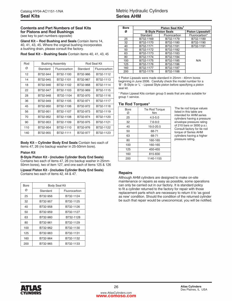
Contents and Part Numbers of Seal Kits for Pistons and Rod Bushings (see key to part numbers opposite)Gland Kit – Rod Bushing and Seals Contain items 14, 40, 41, 43, 45. Where the original bushing incorporates a bushing drain, please consult the factory.Rod Seal Kit – Bushing Seals Contain items 40, 41, 43, 45
Body Kit – Cylinder Body End Seals Contain two each of items 47, �6 (no backup washer in �5-50mm bore).
Piston Kit B-Style Piston Kit - (includes Cylinder Body End Seals) Contains two each of items 47, �6 (no backup washer in �5mm-50mm bores), two of item 1�7, and one each of items 1�5 & 1�6Lipseal Piston Kit - (includes Cylinder Body End Seals) Contains two each of items 4�, 44 & 47.
Tie Rod Torques*
Rod Bushing Assembly Rod Seal Kit
Ø Standard Fluorocarbon Standard Fluorocarbon
1� B73�-944 B73�-1100 B73�-966 B73�-111�
14 B73�-945 B73�-1101 B73�-967 B73�-1113
18 B73�-946 B73�-110� B73�-968 B73�-1114
�� B73�-947 B73�-1103 B73�-969 B73�-1115
�8 B73�-948 B73�-1104 B73�-970 B73�-1116
36 B73�-949 B73�-1105 B73�-971 B73�-1117
45 B73�-950 B73�-1106 B73�-97� B73�-1118
56 B73�-951 B73�-1107 B73�-973 B73�-1119
70 B73�-95� B73�-1108 B73�-974 B73�-11�0
90 B73�-953 B73�-1109 B73�-975 B73�-11�1
110 B73�-954 B73�-1110 B73�-976 B73�-11��
140 B73�-955 B73�-1111 B73�-977 B73�-11�3
RepairsAlthough AHM cylinders are designed to make on-site maintenance or repairs as easy as possible, some operations can only be carried out in our factory. It is standard policy to fit a cylinder returned to the factory for repair with those replacement parts which are necessary to return it to ‘as good as new’ condition. Should the condition of the returned cylinder be such that repair would be uneconomical, you will be notified.
Bore Tie Rod Torque Ø Nm �5 4.5-5.0 3� 7.6-9.0 40 19.0-�0.5 50 68-71 63 68-71 80 160-165 100 160-165 1�5 450-455 160 815-830 �00 1140-1155
The tie rod torque values listed in this table are intended for AHM series cylinders having a pressure envelope pressure rating of �10 bars or 3000 p.s.i. Consult factory for tie rod torque of Series AHM cylinders having a higher pressure rating.
Seal Kits
Bore Body Seal Kit
Ø Standard Fluorocarbon
�5 B73�-956 B73�-11�4
3� B73�-957 B73�-11�5
40 B73�-958 B73�-11�6
50 B73�-959 B73�-11�7
63 B73�-960 B73�-11�8
80 B73�-961 B73�-11�9
100 B73�-96� B73�-1130
1�5 B73�-963 B73�-1131
160 B73�-964 B73�-113�
�00 B73�-965 B73�-1133
† Piston Lipseals were made standard in �5mm - 40mm bores beginning in June �006. Carefully check the model number for a ‘B’ - B-Style or ‘L’ - Lipseal Style piston before specifying a piston seal kit.
* Piston Lipseal Kits contain group 5 seals that are also suitable for group 1 service.
Piston Lipseals®Standard Fluorocarbon Fluorocarbon*
25 B732-1169 B732-1179 B732-118932 B732-1170 B732-1180 B732-119040 B732-1171 B732-1181 B732-119150 B732-1172 B732-118263 B732-1173 B732-118380 B732-1174 B732-1184100 B732-1175 B732-1185125 B732-1176 B732-1186160 B732-1177 B732-1187200 B732-1178 B732-1188
Piston Seal Kits†
B-Style Piston SealsBore
Ø
N/A
www.comoso.com
Metric Hydraulic CylindersSeries AHM
Catalog HY04-AC1151-1/NA
�7 Atlas CylindersDes Plaines, IL USA
www.AtlasCylinders.com
Mounting Information
Mounting StylesGeneral guidance for the selection of ISO mounting styles can be found in the AHM content of Section B. The notes which follow provide information for use in specific applications and should be read in conjunction with that information.
TrunnionsTrunnions require lubricated pillow blocks with minimum bearing clearances. Blocks should be aligned and mounted to eliminate bending moments on the trunnion pins. Self-aligning mounts must not be used to support the trunnions as bending forces can develop.Intermediate trunnions may be positioned at any point on the cylinder body. This position, dimension XI, should be specified at the time of order. Trunnion position is not field adjustable.
Flange MountingsFront flange-mounted (style JJ) cylinders incorporate a pilot diameter for accurate alignment on the mounting surface – see rod end dimensions for AHM cylinders. The gland retainer is integral with the head on �5, 3� and 40mm bore cylinders,
All dimensions are in millimeters unless otherwise stated.
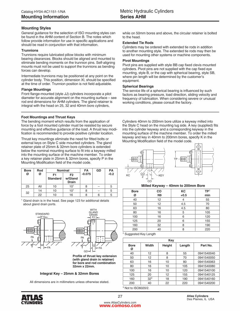
Foot Mountings and Thrust KeysThe bending moment which results from the application of force by a foot mounted cylinder must be resisted by secure mounting and effective guidance of the load. A thrust key modi-fication is recommended to provide positive cylinder location.
Thrust key mountings eliminate the need for fitted bolts or external keys on Style C side mounted cylinders. The gland retainer plate of �5mm & 3�mm bore cylinders is extended below the nominal mounting surface to fit into a keyway milled into the mounting surface of the machine member. To order a key retainer plate in �5mm & 3�mm bores, specify P in the Mounting Modification field of the model code.
Integral Key – 25mm & 32mm Bores
BoreØ
CO N9
KC +0.5
TP�
min40 1� 4 5550 1� 4.5 7063 16 4.5 8080 16 5 105100 16 6 1�01�5 �0 6 155160 3� 8 190�00 40 8 ��0
� Suggested Key Length
KeyBore
ØWidth Height Length Part No.
40 1� 8 55 094154004050 1� 8 70 094154005063 16 10 80 094154006380 16 10 105 0941540080100 16 10 1�0 09415401001�5 �0 1� 155 09415401�5160 3�3 18 190 0941540160�00 40 �� ��0 0941540�00
KC KEYCO2
CO
TP
Milled Keyway – 40mm to 200mm Bore
Bore Ø
Rod Ø
Nominal FA -0.075
GD PA -0.2F1
StandardF2
w/Gland Drain
�5 All 10 101 8 – 5
3�14 10 101 8 – 5�� 10 16 8 6 5
1 Gland drain is in the head. See page 1�3 for additional details about gland drain ports.
while on 50mm bores and above, the circular retainer is bolted to the head.
Extended Tie RodsCylinders may be ordered with extended tie rods in addition to another mounting style. The extended tie rods may then be used for mounting other systems or machine components.
Pivot MountingsPivot pins are supplied with style BB cap fixed clevis mounted cylinders. Pivot pins are not supplied with the cap fixed eye mounting, style B, or the cap with spherical bearing, style SB, where pin length will be determined by the customer’s equipment.
Spherical BearingsThe service life of a spherical bearing is influenced by such factors as bearing pressure, load direction, sliding velocity and frequency of lubrication. When considering severe or unusual working conditions, please consult the factory.
Profile of thrust key extension (with gland drain in retainer) for bore and rod combination 32mm x 22mm.
FA
PA
F2
WITHGLANDDRAIN
GDFA
PA
F1STANDARD
Cylinders 40mm to �00mm bore utilize a keyway milled into the Style C head on the mounting lug side. A key (supplied) fits into the cylinder keyway and a corresponding keyway in the mounting surface of the machine member. To order the milled keyway and key in 40mm to �00mm bores, specify K in the Mounting Modification field of the model code.
3 Not to ISO60�0/�.
www.comoso.com
Metric Hydraulic CylindersSeries AHM
Catalog HY04-AC1151-1/NA
�8 Atlas CylindersDes Plaines, IL USA
www.AtlasCylinders.com
Mounting Information
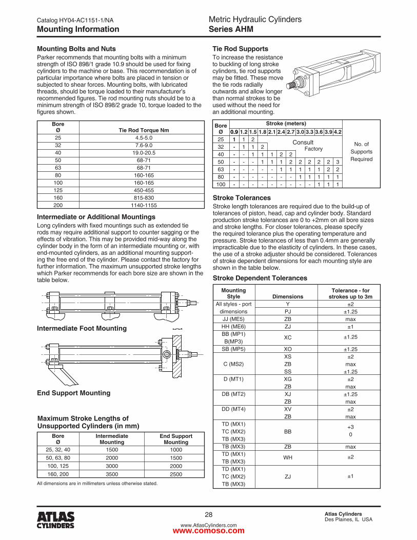
Tie Rod SupportsTo increase the resistance to buckling of long stroke cylinders, tie rod supports may be fitted. These move the tie rods radially outwards and allow longer than normal strokes to be used without the need for an additional mounting.
2.1
11---
1.8
�11---
2.4
�11--
3.0
�11-
2.7
��1--
3.3
�11-
3.6
�111
1.5�11----
1.211-----
Intermediate Mounting
1500�00030003500
Intermediate or Additional MountingsLong cylinders with fixed mountings such as extended tie rods may require additional support to counter sagging or the effects of vibration. This may be provided mid-way along the cylinder body in the form of an intermediate mounting or, with end-mounted cylinders, as an additional mounting support-ing the free end of the cylinder. Please contact the factory for further information. The maximum unsupported stroke lengths which Parker recommends for each bore size are shown in the table below.
Intermediate Foot Mounting
End Support Mounting
Maximum Stroke Lengths of Unsupported Cylinders (in mm)
Stroke TolerancesStroke length tolerances are required due to the build-up of tolerances of piston, head, cap and cylinder body. Standard production stroke tolerances are 0 to +�mm on all bore sizes and stroke lengths. For closer tolerances, please specify the required tolerance plus the operating temperature and pressure. Stroke tolerances of less than 0.4mm are generally impracticable due to the elasticity of cylinders. In these cases, the use of a stroke adjuster should be considered. Tolerances of stroke dependent dimensions for each mounting style are shown in the table below.
Stroke Dependent Tolerances
Bore Ø
�5, 3�, 4050, 63, 80100, 1�5160, �00
End Support Mounting
10001500�000�500
DimensionsYPJZBZJ
XC
XOXSZBSSXGZBXJZBXVZB
BB
ZB
WH
ZJ
MountingStyle
All styles - port dimensionsJJ (ME5)HH (ME6)BB (MP1)B(MP3)
SB (MP5)
C (MS�)
D (MT1)
DB (MT�)
DD (MT4)
TD (MX1)TC (MX�)TB (MX3)TB (MX3)TD (MX1)TB (MX3)TD (MX1)TC (MX�)TB (MX3)
Tolerance - forstrokes up to 3m
±�±1.�5max±1
±1.�5
±1.�5±�
max±1.�5
±�max
±1.�5max±�
max
+30
max
±�
±1
Bore�53�40506380
100
No. ofSupportsRequired
0.91------
0.91------
3.9
��11
4.2
3�11
Stroke (meters)
All dimensions are in millimeters unless otherwise stated.
Consult Factory
Mounting Bolts and NutsParker recommends that mounting bolts with a minimum strength of ISO 898/1 grade 10.9 should be used for fixing cylinders to the machine or base. This recommendation is of particular importance where bolts are placed in tension or subjected to shear forces. Mounting bolts, with lubricated threads, should be torque loaded to their manufacturer’s recommended figures. Tie rod mounting nuts should be to a minimum strength of ISO 898/� grade 10, torque loaded to the figures shown.
Bore�53�40506380
1001�5160�00
Tie Rod Torque Nm4.5-5.07.6-9.0
19.0-�0.568-7168-71
160-165160-165450-455815-830
1140-1155
PD
or
PE PA
W
INTEGRAL KEYFA
STOP PINSEAL FOR THREADS 1" & UP
D-THREADS
J-WRENCH SQUARE
SEAL FOR 1/2& 3/4 THREADSK (MIN.)L
PD
or
PE PA
W
INTEGRAL KEYPT
www.comoso.com
Metric Hydraulic CylindersSeries AHM
Catalog HY04-AC1151-1/NA
�9 Atlas CylindersDes Plaines, IL USA
www.AtlasCylinders.com
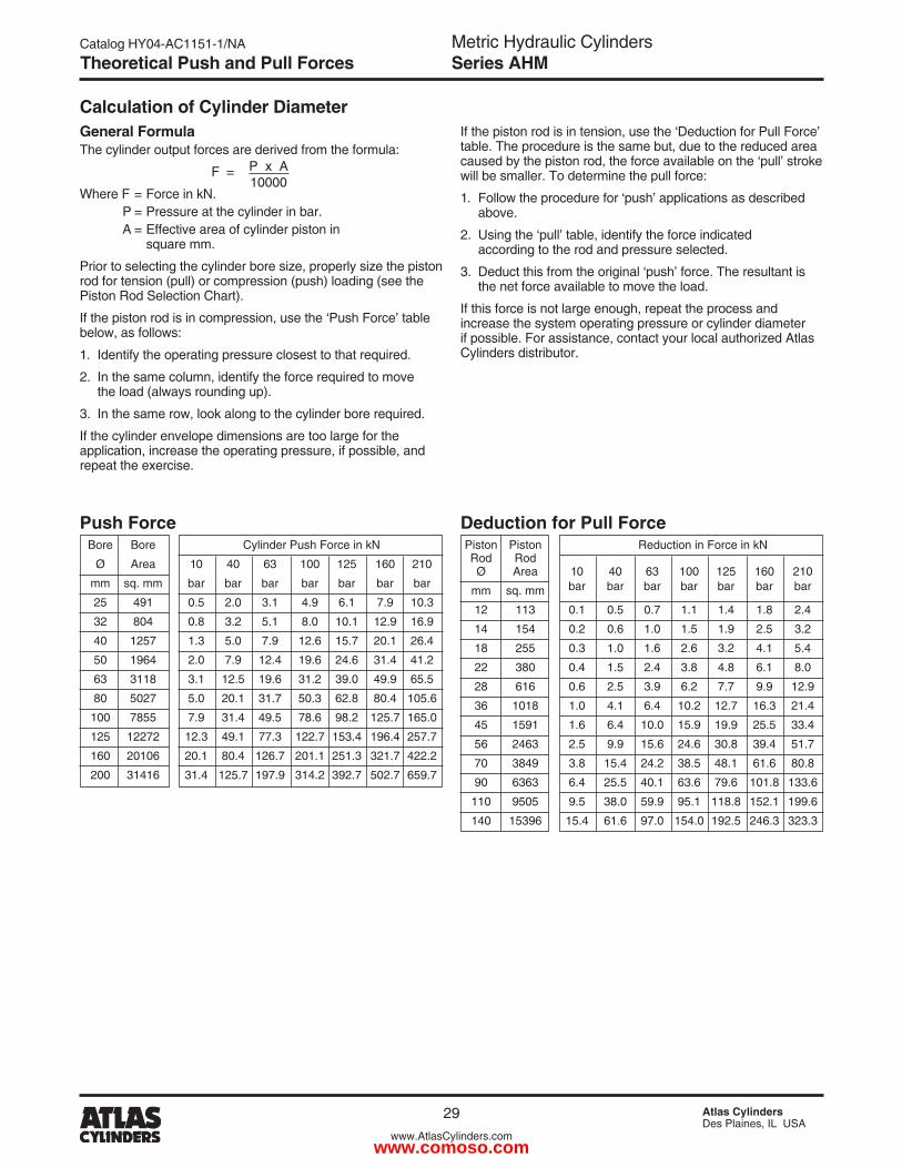
If the piston rod is in tension, use the ‘Deduction for Pull Force’ table. The procedure is the same but, due to the reduced area caused by the piston rod, the force available on the ‘pull’ stroke will be smaller. To determine the pull force:
1. Follow the procedure for ‘push’ applications as described above.
�. Using the ‘pull’ table, identify the force indicated according to the rod and pressure selected.
3. Deduct this from the original ‘push’ force. The resultant is the net force available to move the load.
If this force is not large enough, repeat the process and increase the system operating pressure or cylinder diameter if possible. For assistance, contact your local authorized Atlas Cylinders distributor.
Deduction for Pull Force
P x A10000
Calculation of Cylinder DiameterGeneral FormulaThe cylinder output forces are derived from the formula:
F =
Where F = Force in kN. P = Pressure at the cylinder in bar. A = Effective area of cylinder piston in square mm.
Prior to selecting the cylinder bore size, properly size the piston rod for tension (pull) or compression (push) loading (see the Piston Rod Selection Chart).
If the piston rod is in compression, use the ‘Push Force’ table below, as follows:
1. Identify the operating pressure closest to that required.
�. In the same column, identify the force required to move the load (always rounding up).
3. In the same row, look along to the cylinder bore required.
If the cylinder envelope dimensions are too large for the application, increase the operating pressure, if possible, and repeat the exercise.
Push Force Bore Bore Cylinder Push Force in kN
Ø Area 10 40 63 100 1�5 160 �10
mm sq. mm bar bar bar bar bar bar bar
�5 491 0.5 �.0 3.1 4.9 6.1 7.9 10.3
3� 804 0.8 3.� 5.1 8.0 10.1 1�.9 16.9
40 1�57 1.3 5.0 7.9 1�.6 15.7 �0.1 �6.4
50 1964 �.0 7.9 1�.4 19.6 �4.6 31.4 41.�
63 3118 3.1 1�.5 19.6 31.� 39.0 49.9 65.5
80 50�7 5.0 �0.1 31.7 50.3 6�.8 80.4 105.6
100 7855 7.9 31.4 49.5 78.6 98.� 1�5.7 165.0
1�5 1��7� 1�.3 49.1 77.3 1��.7 153.4 196.4 �57.7
160 �0106 �0.1 80.4 1�6.7 �01.1 �51.3 3�1.7 4��.�
�00 31416 31.4 1�5.7 197.9 314.� 39�.7 50�.7 659.7
Piston Piston Reduction in Force in kN Rod Rod Ø Area 10 40 63 100 1�5 160 �10
mm sq. mm bar bar bar bar bar bar bar
1� 113 0.1 0.5 0.7 1.1 1.4 1.8 �.4
14 154 0.� 0.6 1.0 1.5 1.9 �.5 3.�
18 �55 0.3 1.0 1.6 �.6 3.� 4.1 5.4
�� 380 0.4 1.5 �.4 3.8 4.8 6.1 8.0
�8 616 0.6 �.5 3.9 6.� 7.7 9.9 1�.9
36 1018 1.0 4.1 6.4 10.� 1�.7 16.3 �1.4
45 1591 1.6 6.4 10.0 15.9 19.9 �5.5 33.4
56 �463 �.5 9.9 15.6 �4.6 30.8 39.4 51.7
70 3849 3.8 15.4 �4.� 38.5 48.1 61.6 80.8
90 6363 6.4 �5.5 40.1 63.6 79.6 101.8 133.6
110 9505 9.5 38.0 59.9 95.1 118.8 15�.1 199.6
140 15396 15.4 61.6 97.0 154.0 19�.5 �46.3 3�3.3
Theoretical Push and Pull Forces
www.comoso.com
Metric Hydraulic CylindersSeries AHM
Catalog HY04-AC1151-1/NA
30 Atlas CylindersDes Plaines, IL USA
www.AtlasCylinders.com
Cushion Sleeve Stop Tube
1000
10000
8
8
9
9
7
7
6
6
5
5
4
4
3
3
�
�
1 � 3 4 5 6 7 8 9 10 � 3 4 5 6 7 8 9100 � 3 4 5 6 7 8 91000 � 3 4 5
Rod Diameter (mm)
Thrust (kN) – Log Scale Consult Factory
Fixe
d M
ount
ings
Piv
ot M
ount
ings
2550
100150200
50
10015020075
125175
25
75125175
No
Sto
p T
ube
Req
uire
d
Recommended Lengthof Stop Tube (mm)
Bas
ic L
eng
th (m
m) _
Lo
g S
cale 140 Ø110 Ø90 Ø
70 Ø56 Ø
45 Ø
36 Ø
28 Ø
22 Ø18 Ø
14 Ø12 Ø
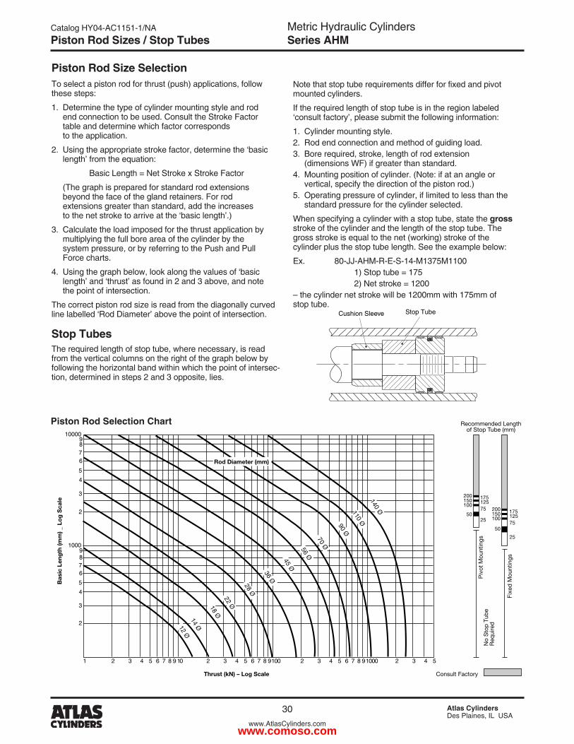
Piston Rod Size SelectionTo select a piston rod for thrust (push) applications, follow these steps:
1. Determine the type of cylinder mounting style and rod end connection to be used. Consult the Stroke Factor table and determine which factor corresponds to the application.
�. Using the appropriate stroke factor, determine the ‘basic length’ from the equation:
Basic Length = Net Stroke x Stroke Factor
(The graph is prepared for standard rod extensions beyond the face of the gland retainers. For rod extensions greater than standard, add the increases to the net stroke to arrive at the ‘basic length’.)
3. Calculate the load imposed for the thrust application by multiplying the full bore area of the cylinder by the system pressure, or by referring to the Push and Pull Force charts.
4. Using the graph below, look along the values of ‘basic length’ and ‘thrust’ as found in � and 3 above, and note the point of intersection.
The correct piston rod size is read from the diagonally curved line labelled ‘Rod Diameter’ above the point of intersection.
Stop TubesThe required length of stop tube, where necessary, is read from the vertical columns on the right of the graph below by following the horizontal band within which the point of intersec-tion, determined in steps � and 3 opposite, lies.
Note that stop tube requirements differ for fixed and pivot mounted cylinders.
If the required length of stop tube is in the region labeled ‘consult factory’, please submit the following information:
1. Cylinder mounting style.�. Rod end connection and method of guiding load.3. Bore required, stroke, length of rod extension (dimensions WF) if greater than standard.4. Mounting position of cylinder. (Note: if at an angle or vertical, specify the direction of the piston rod.)5. Operating pressure of cylinder, if limited to less than the standard pressure for the cylinder selected.
When specifying a cylinder with a stop tube, state the gross stroke of the cylinder and the length of the stop tube. The gross stroke is equal to the net (working) stroke of the cylinder plus the stop tube length. See the example below:
Ex. 80-JJ-AHM-R-E-S-14-M1375M1100 1) Stop tube = 175 �) Net stroke = 1�00– the cylinder net stroke will be 1�00mm with 175mm of stop tube.
Piston Rod Selection Chart
Piston Rod Sizes / Stop Tubes
www.comoso.com
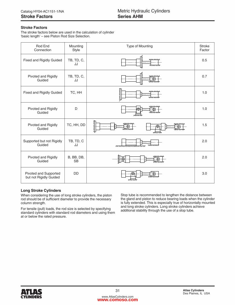
Metric Hydraulic CylindersSeries AHM
Catalog HY04-AC1151-1/NA
31 Atlas CylindersDes Plaines, IL USA
www.AtlasCylinders.com
Pivoted and Rigidly D 1.0 Guided
Supported but not Rigidly TB, TD, C �.0 Guided JJ
Pivoted and Rigidly B, BB, DB, �.0 Guided SB
Pivoted and Supported DD 3.0 but not Rigidly Guided
Pivoted and Rigidly TC, HH, DD 1.5 Guided
Stroke FactorsThe stroke factors below are used in the calculation of cylinder ‘basic length’ – see Piston Rod Size Selection.
Rod End Mounting Type of Mounting Stroke Connection Style Factor
Fixed and Rigidly Guided TB, TD, C, 0.5 JJ
Pivoted and Rigidly TB, TD, C, 0.7 Guided JJ
Fixed and Rigidly Guided TC, HH 1.0
Long Stroke CylindersWhen considering the use of long stroke cylinders, the piston rod should be of sufficient diameter to provide the necessary column strength.
For tensile (pull) loads, the rod size is selected by specifying standard cylinders with standard rod diameters and using them at or below the rated pressure.
Stop tube is recommended to lengthen the distance between the gland and piston to reduce bearing loads when the cylinder is fully extended. This is especially true of horizontally mounted and long stroke cylinders. Long stroke cylinders achieve additional stability through the use of a stop tube.
Stroke Factors
www.comoso.com
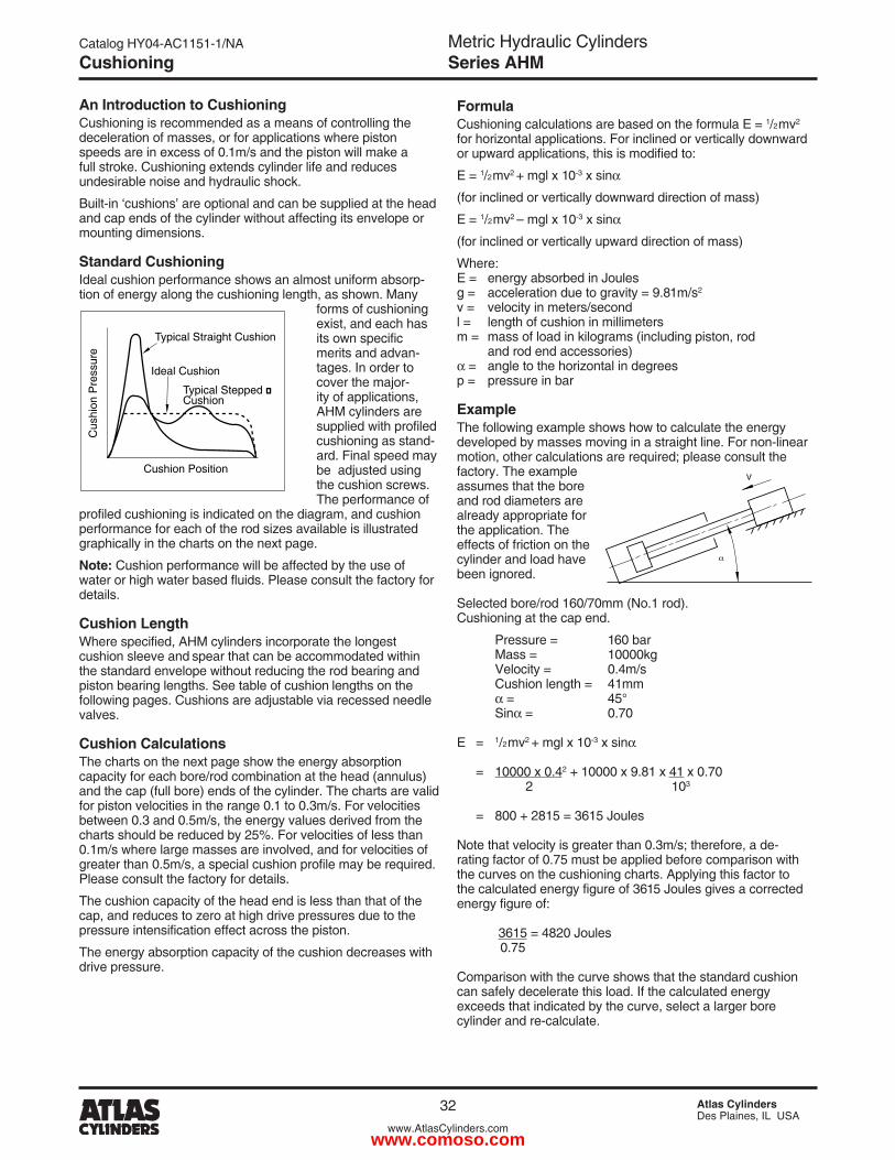
Metric Hydraulic CylindersSeries AHM
Catalog HY04-AC1151-1/NA
3� Atlas CylindersDes Plaines, IL USA
www.AtlasCylinders.com
FormulaCushioning calculations are based on the formula E = 1/�mv� for horizontal applications. For inclined or vertically downward or upward applications, this is modified to:
E = 1/�mv� + mgl x 10-3 x sin
(for inclined or vertically downward direction of mass)
E = 1/�mv� – mgl x 10-3 x sin
(for inclined or vertically upward direction of mass)
Where:E = energy absorbed in Joulesg = acceleration due to gravity = 9.81m/s�
v = velocity in meters/secondl = length of cushion in millimetersm = mass of load in kilograms (including piston, rod and rod end accessories) = angle to the horizontal in degreesp = pressure in bar
ExampleThe following example shows how to calculate the energy developed by masses moving in a straight line. For non-linear motion, other calculations are required; please consult the factory. The example assumes that the bore and rod diameters are already appropriate for the application. The effects of friction on the cylinder and load have been ignored.
Selected bore/rod 160/70mm (No.1 rod).Cushioning at the cap end.
Pressure = 160 bar Mass = 10000kg Velocity = 0.4m/s Cushion length = 41mm = 45° Sin = 0.70
E = 1/�mv� + mgl x 10-3 x sin
= 10000 x 0.4� + 10000 x 9.81 x 41 x 0.70 � 103
= 800 + �815 = 3615 Joules
Note that velocity is greater than 0.3m/s; therefore, a de- rating factor of 0.75 must be applied before comparison with the curves on the cushioning charts. Applying this factor to the calculated energy figure of 3615 Joules gives a corrected energy figure of:
3615 = 48�0 Joules 0.75
Comparison with the curve shows that the standard cushion can safely decelerate this load. If the calculated energy exceeds that indicated by the curve, select a larger bore cylinder and re-calculate.
An Introduction to CushioningCushioning is recommended as a means of controlling the deceleration of masses, or for applications where piston speeds are in excess of 0.1m/s and the piston will make a full stroke. Cushioning extends cylinder life and reduces undesirable noise and hydraulic shock.
Built-in ‘cushions’ are optional and can be supplied at the head and cap ends of the cylinder without affecting its envelope or mounting dimensions.
Standard CushioningIdeal cushion performance shows an almost uniform absorp-tion of energy along the cushioning length, as shown. Many
forms of cushioning exist, and each has its own specific merits and advan-tages. In order to cover the major-ity of applications, AHM cylinders are supplied with profiled cushioning as stand-ard. Final speed may be adjusted using the cushion screws. The performance of
profiled cushioning is indicated on the diagram, and cushion performance for each of the rod sizes available is illustrated graphically in the charts on the next page.
Note: Cushion performance will be affected by the use of water or high water based fluids. Please consult the factory for details.
Cushion LengthWhere specified, AHM cylinders incorporate the longest cushion sleeve and spear that can be accommodated within the standard envelope without reducing the rod bearing and piston bearing lengths. See table of cushion lengths on the following pages. Cushions are adjustable via recessed needle valves.
Cushion CalculationsThe charts on the next page show the energy absorption capacity for each bore/rod combination at the head (annulus) and the cap (full bore) ends of the cylinder. The charts are valid for piston velocities in the range 0.1 to 0.3m/s. For velocities between 0.3 and 0.5m/s, the energy values derived from the charts should be reduced by �5%. For velocities of less than 0.1m/s where large masses are involved, and for velocities of greater than 0.5m/s, a special cushion profile may be required. Please consult the factory for details.
The cushion capacity of the head end is less than that of the cap, and reduces to zero at high drive pressures due to the pressure intensification effect across the piston.
The energy absorption capacity of the cushion decreases with drive pressure.
Cus
hion
Pre
ssur
e
Typical Straight Cushion
Cushion Position
Ideal Cushion
Typical Stepped �Cushion
Cushioning
www.comoso.com
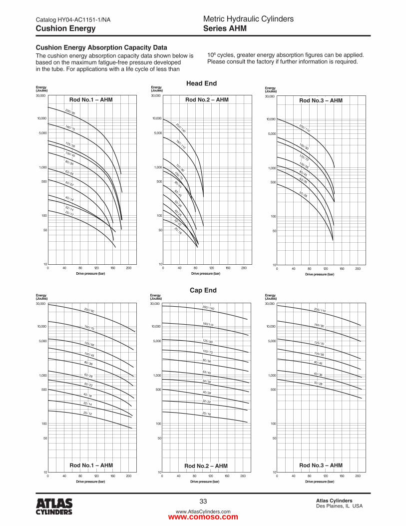
Metric Hydraulic CylindersSeries AHM
Catalog HY04-AC1151-1/NA
33 Atlas CylindersDes Plaines, IL USA
www.AtlasCylinders.com
10,000
30,000
Energy(Joules)
Drive pressure (bar)
5,000
1,000
500
100
50
100 40 80 120 160 200
Rod No.2 – AHM
200 / 140
160/110
125 / 90
100 / 70
80 / 56
63 / 45
50 / 36
40 / 28
32 / 22
25 / 18
10,000
30,000
Energy(Joules)
Drive pressure (bar)
5,000
1,000
500
100
50
100 40 80 120 160 200
Rod No.2 – AHM
200 / 140
160 / 110
125 / 90100 / 7080 / 5663 / 45
50 / 3640 / 28
32 / 2225 / 18
Cushion Energy Absorption Capacity DataThe cushion energy absorption capacity data shown below is based on the maximum fatigue-free pressure developed in the tube. For applications with a life cycle of less than
106 cycles, greater energy absorption figures can be applied. Please consult the factory if further information is required.
Head End
Cap End
10,000
30,000
Energy(Joules)
Drive pressure (bar)
5,000
1,000
500
100
50
100 40 80 120 160 200
Rod No.1 – AHM
200 / 90
160 / 70
125 / 56
100 / 45
80 / 36
50 / 22
40 / 18
32 / 14
25 / 12
63 / 28
10,000
30,000
Energy(Joules)
Drive pressure (bar)
5,000
1,000
500
100
50
100 40 80 120 160 200
Rod No.1 – AHM 200 / 90
160 / 70
125 / 56
100 / 45
80 / 36
63 / 28
50 / 22
40 / 18
32 / 1425 / 12
10,000
30,000
Energy(Joules)
Drive pressure (bar)
5,000
1,000
500
100
50
100 40 80 120 160 200
Rod No.3 – AHM
200 / 110
160 / 90
125 / 70100 / 5680 / 4563 / 36
50 / 28
10,000
30,000
Energy(Joules)
Drive pressure (bar)
5,000
1,000
500
100
50
100 40 80 120 160 200
Rod No.3 – AHM
200 / 110
160 / 90
125 / 70
100 / 56
80 / 45
63 / 36
50 / 28
Cushion Energy
www.comoso.com
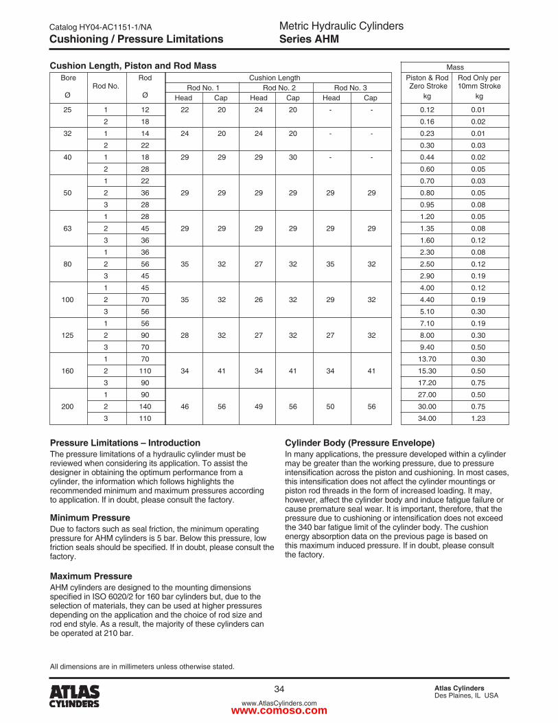
Metric Hydraulic CylindersSeries AHM
Catalog HY04-AC1151-1/NA
34 Atlas CylindersDes Plaines, IL USA
www.AtlasCylinders.com
Bore Rod Cushion Length Piston & Rod Rod Only per Rod No. Rod No. 1 Rod No. � Rod No. 3 Zero Stroke 10mm Stroke
Ø Ø Head Cap Head Cap Head Cap kg kg
�5 1 1� �� �0 �4 �0 - - 0.1� 0.01
� 18 0.16 0.0�
3� 1 14 �4 �0 �4 �0 - - 0.�3 0.01
� �� 0.30 0.03
40 1 18 �9 �9 �9 30 - - 0.44 0.0�
� �8 0.60 0.05
1 �� 0.70 0.03
50 � 36 �9 �9 �9 �9 �9 �9 0.80 0.05
3 �8 0.95 0.08
1 �8 1.�0 0.05
63 � 45 �9 �9 �9 �9 �9 �9 1.35 0.08
3 36 1.60 0.1�
1 36 �.30 0.08
80 � 56 35 3� �7 3� 35 3� �.50 0.1�
3 45 �.90 0.19
1 45 4.00 0.1�
100 � 70 35 3� �6 3� �9 3� 4.40 0.19
3 56 5.10 0.30
1 56 7.10 0.19
1�5 � 90 �8 3� �7 3� �7 3� 8.00 0.30
3 70 9.40 0.50
1 70 13.70 0.30
160 � 110 34 41 34 41 34 41 15.30 0.50
3 90 17.�0 0.75
1 90 �7.00 0.50
�00 � 140 46 56 49 56 50 56 30.00 0.75
3 110 34.00 1.�3
Cushion Length, Piston and Rod Mass
All dimensions are in millimeters unless otherwise stated.
Pressure Limitations – IntroductionThe pressure limitations of a hydraulic cylinder must be reviewed when considering its application. To assist the designer in obtaining the optimum performance from a cylinder, the information which follows highlights the recommended minimum and maximum pressures according to application. If in doubt, please consult the factory.
Minimum PressureDue to factors such as seal friction, the minimum operating pressure for AHM cylinders is 5 bar. Below this pressure, low friction seals should be specified. If in doubt, please consult the factory.
Maximum PressureAHM cylinders are designed to the mounting dimensions specified in ISO 6020/2 for 160 bar cylinders but, due to the selection of materials, they can be used at higher pressures depending on the application and the choice of rod size and rod end style. As a result, the majority of these cylinders can be operated at �10 bar.
Cylinder Body (Pressure Envelope)In many applications, the pressure developed within a cylinder may be greater than the working pressure, due to pressure intensification across the piston and cushioning. In most cases, this intensification does not affect the cylinder mountings or piston rod threads in the form of increased loading. It may, however, affect the cylinder body and induce fatigue failure or cause premature seal wear. It is important, therefore, that the pressure due to cushioning or intensification does not exceed the 340 bar fatigue limit of the cylinder body. The cushion energy absorption data on the previous page is based on this maximum induced pressure. If in doubt, please consult the factory.
Mass
Cushioning / Pressure Limitations
www.comoso.com
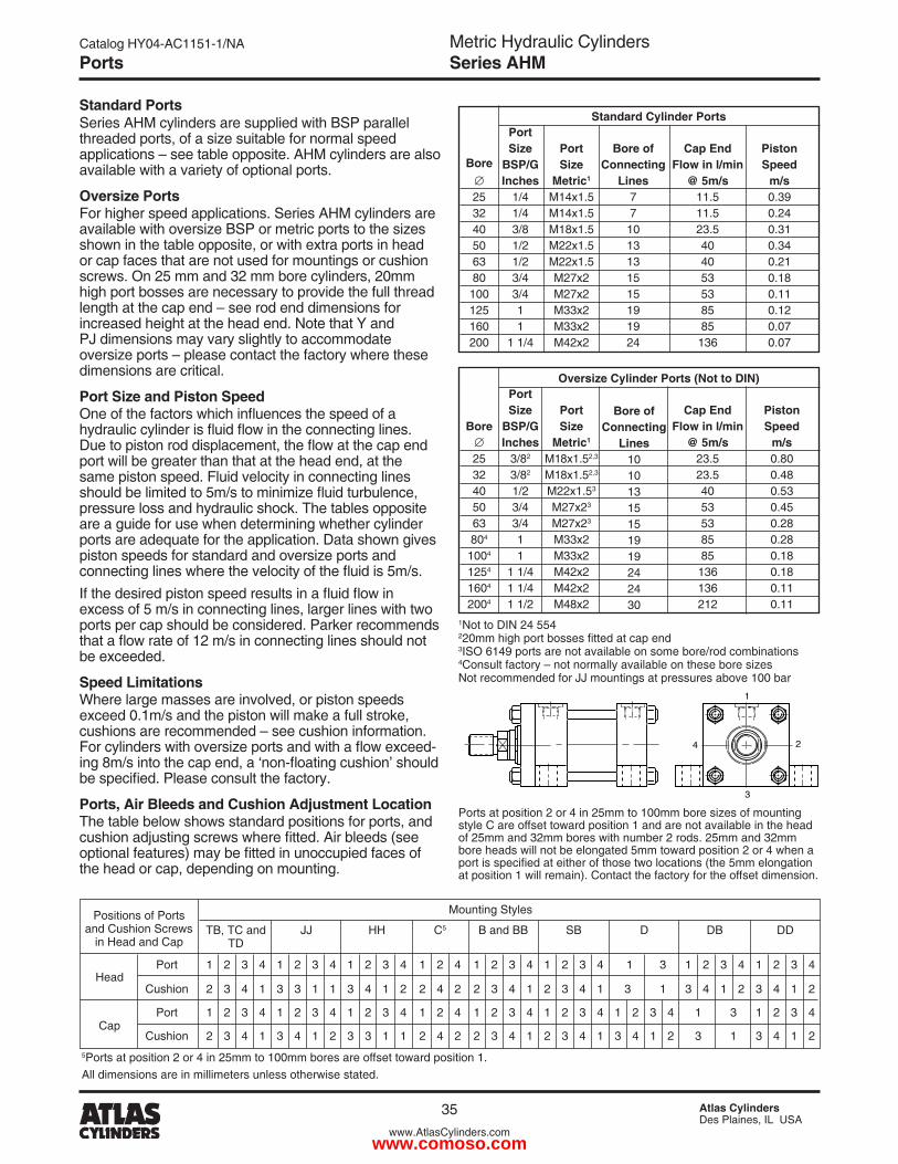
Metric Hydraulic CylindersSeries AHM
Catalog HY04-AC1151-1/NA
35 Atlas CylindersDes Plaines, IL USA
www.AtlasCylinders.com
Ports
Standard Cylinder Ports
Piston Speed
m/s0.390.�40.310.340.�10.180.110.1�0.070.07
Standard PortsSeries AHM cylinders are supplied with BSP parallel threaded ports, of a size suitable for normal speed applications – see table opposite. AHM cylinders are also available with a variety of optional ports.
Oversize PortsFor higher speed applications. Series AHM cylinders are available with oversize BSP or metric ports to the sizes shown in the table opposite, or with extra ports in head or cap faces that are not used for mountings or cushion screws. On �5 mm and 3� mm bore cylinders, �0mm high port bosses are necessary to provide the full thread length at the cap end – see rod end dimensions for increased height at the head end. Note that Y and PJ dimensions may vary slightly to accommodate oversize ports – please contact the factory where these dimensions are critical.
Port Size and Piston SpeedOne of the factors which influences the speed of a hydraulic cylinder is fluid flow in the connecting lines. Due to piston rod displacement, the flow at the cap end port will be greater than that at the head end, at the same piston speed. Fluid velocity in connecting lines should be limited to 5m/s to minimize fluid turbulence, pressure loss and hydraulic shock. The tables opposite are a guide for use when determining whether cylinder ports are adequate for the application. Data shown gives piston speeds for standard and oversize ports and connecting lines where the velocity of the fluid is 5m/s.If the desired piston speed results in a fluid flow in excess of 5 m/s in connecting lines, larger lines with two ports per cap should be considered. Parker recommends that a flow rate of 12 m/s in connecting lines should not be exceeded.
Speed LimitationsWhere large masses are involved, or piston speeds exceed 0.1m/s and the piston will make a full stroke, cushions are recommended – see cushion information. For cylinders with oversize ports and with a flow exceed-ing 8m/s into the cap end, a ‘non-floating cushion’ should be specified. Please consult the factory.
Ports, Air Bleeds and Cushion Adjustment LocationThe table below shows standard positions for ports, and cushion adjusting screws where fitted. Air bleeds (see optional features) may be fitted in unoccupied faces of the head or cap, depending on mounting.
1Not to DIN �4 554�20mm high port bosses fitted at cap end3ISO 6149 ports are not available on some bore/rod combinations4Consult factory – not normally available on these bore sizesNot recommended for JJ mountings at pressures above 100 bar
Bore ofConnecting
Lines77
10131315151919�4
Bore�53�40506380
1001�5160�00
PortSize
BSP/GInches
1/41/43/81/�1/�3/43/411
1 1/4
Cap EndFlow in l/min
@ 5m/s11.511.5�3.5404053538585
136
PortSize
Metric1
M14x1.5M14x1.5M18x1.5M��x1.5M��x1.5M�7x�M�7x�M33x�M33x�M4�x�
Oversize Cylinder Ports (Not to DIN)
Piston Speed
m/s0.800.480.530.450.�80.�80.180.180.110.11
Bore ofConnecting
Lines10101315151919�4�430
Bore�53�405063804
1004
1�54
1604
�004
PortSize
BSP/GInches
3/8�
3/8�
1/�3/43/411
1 1/41 1/41 1/�
Cap EndFlow in l/min
@ 5m/s�3.5�3.54053538585
136136�1�
PortSize
Metric1
M18x1.5�,3
M18x1.5�,3
M��x1.53
M�7x�3
M�7x�3
M33x�M33x�M4�x�M4�x�M48x�
4 �
1
3
Positions of Ports Mounting Styles
and Cushion Screws TB, TC and JJ HH C5 B and BB SB D DB DD in Head and Cap TD
Port 1 � 3 4 1 � 3 4 1 � 3 4 1 � 4 1 � 3 4 1 � 3 4 1 3 1 � 3 4 1 � 3 4 Head Cushion � 3 4 1 3 3 1 1 3 4 1 � � 4 � � 3 4 1 � 3 4 1 3 1 3 4 1 � 3 4 1 �
Port 1 � 3 4 1 � 3 4 1 � 3 4 1 � 4 1 � 3 4 1 � 3 4 1 � 3 4 1 3 1 � 3 4 Cap Cushion � 3 4 1 3 4 1 � 3 3 1 1 � 4 � � 3 4 1 � 3 4 1 3 4 1 � 3 1 3 4 1 �
All dimensions are in millimeters unless otherwise stated.
5Ports at position 2 or 4 in 25mm to 100mm bores are offset toward position 1.
Ports at position � or 4 in �5mm to 100mm bore sizes of mounting style C are offset toward position 1 and are not available in the head of �5mm and 3�mm bores with number � rods. �5mm and 3�mm bore heads will not be elongated 5mm toward position � or 4 when a port is specified at either of those two locations (the 5mm elongation at position 1 will remain). Contact the factory for the offset dimension.
www.comoso.com
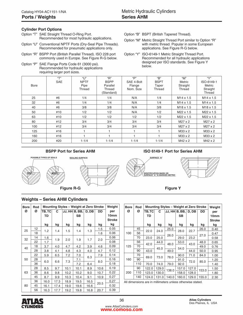
Metric Hydraulic CylindersSeries AHM
Catalog HY04-AC1151-1/NA
36 Atlas CylindersDes Plaines, IL USA
www.AtlasCylinders.com
“T” “U” “R” “P” “B” “M” “Y” SAE NPTF BSPP SAE 4-Bolt BSPT Metric ISO-6149-1 Bore Pipe Parallel Flange Taper Straight Metric Thread Thread Nom. Size Thread Thread Straight (Standard) Thread
�5 #6 1/4 1/4 N/A 1/4 M14 x 1.5 M14 x 1.5 3� #6 1/4 1/4 N/A 1/4 M14 x 1.5 M14 x 1.5 40 #6 3/8 3/8 N/A 3/8 M18 x 1.5 M18 x 1.5 50 #10 1/� 1/� N/A 1/� M�� x 1.5 M�� x 1.5 63 #10 1/� 1/� 1/� 1/� M�� x 1.5 M�� x 1.5 80 #1� 3/4 3/4 3/4 3/4 M�7 x � M�7 x � 100 #1� 3/4 3/4 3/4 3/4 M�7 x � M�7 x � 1�5 #16 1 1 1 1 M33 x � M33 x � 160 #16 1 1 1 1 M33 x � M33 x � �00 #�0 1-1/4 1-1/4 1-1/4 1-1/4 M4� x � M4� x �
Cylinder Port OptionsOption “T” SAE Straight Thread O-Ring Port. Recommended for most hydraulic applications.
Option “U” Conventional NPTF Ports (Dry-Seal Pipe Threads). Recommended for pneumatic applications only.
Option “R” BSPP Port (British Parallel Thread). ISO ��8 port commonly used in Europe. See Figure R-G below.
Option “P” SAE Flange Ports Code 61 (3000 psi). Recommended for hydraulic applications requiring larger port sizes.
Option “B” BSPT (British Tapered Thread).
Option “M” Metric Straight Thread Port similar to Option “R” with metric thread. Popular in some European applications. See Figure R-G below.
Option “Y” ISO-6149-1 Metric Straight Thread Port. Recommended for all hydraulic applications designed per ISO standards. See Figure Y below.
Figure YFigure R-G
BSPP Port for Series AHM ISO 6149-1 Port for Series AHM
Ports / Weights
B, BB,SB
kg
1.4
1.9
4.�4.37.07.17.�
10.110.�10.419.519.619.8
C
kg
1.4
1.9
4.04.16.5
6.6
9.79.89.9
17.317.417.7
DD
kg1.51.6
�.0
4.64.77.9
8.0
10.610.710.9
�0.5
�0.7
BoreØ
�5
3�
40
50
63
80
RodØ
1�1814��18�8���836�83645364556
D, DB
kg
1.3
1.7
3.94.0
6.3
6.48.99.09.1
16.516.616.8
Weightper
10mmStroke
kg0.050.060.060.080.090.1�0.140.160.180.190.��0.�70.�70.3�0.39
JJ, HH
kg
1.5
�.0
4.74.87.�
7.3
10.110.�10.318.919.019.�
TB, TCTD
kg
1.�
1.61.73.73.85.9
6.0
8.58.68.7
16.016.116.3
Mounting Styles – Weight at Zero Stroke
Weights – Series AHM Cylinders
All dimensions are in millimeters unless otherwise stated.
B, BB,SB
kg
�8.0
�9.053.0
54.0
90.091.09�.0
157.0158.0160.0
C
kg
�4.0
�5.044.0
45.0
73.0
74.01�9.0130.0131.0
DD
kg�6.0
�7.0
48.049.050.084.0
85.0
153.0
155.0
BoreØ
100
1�5
160
�00
RodØ
4556705670907090
11090
110140
D, DB
kg
��.7
�3.�
43.0
44.071.0
7�.0
1�7.01�8.01�9.0
Weightper
10mmStroke
kg0.400.470.580.650.760.951.001.�01.401.501.80�.30
JJ, HH
kg�5.0
�6.0
48.0
49.0
78.0
79.0
138.0
140.0
TB, TCTD
kg
��.0
�3.0
4�.0
43.0
69.0
70.01��.01�3.01�4.0
Mounting Styles – Weight at Zero Stroke
POSSIBLE TYPES OF SEALS SEALING SURFACE
IDENTIFICATION MARK ORSURFACE “A” IS MARKED METRIC
SURFACE “A”
www.comoso.com
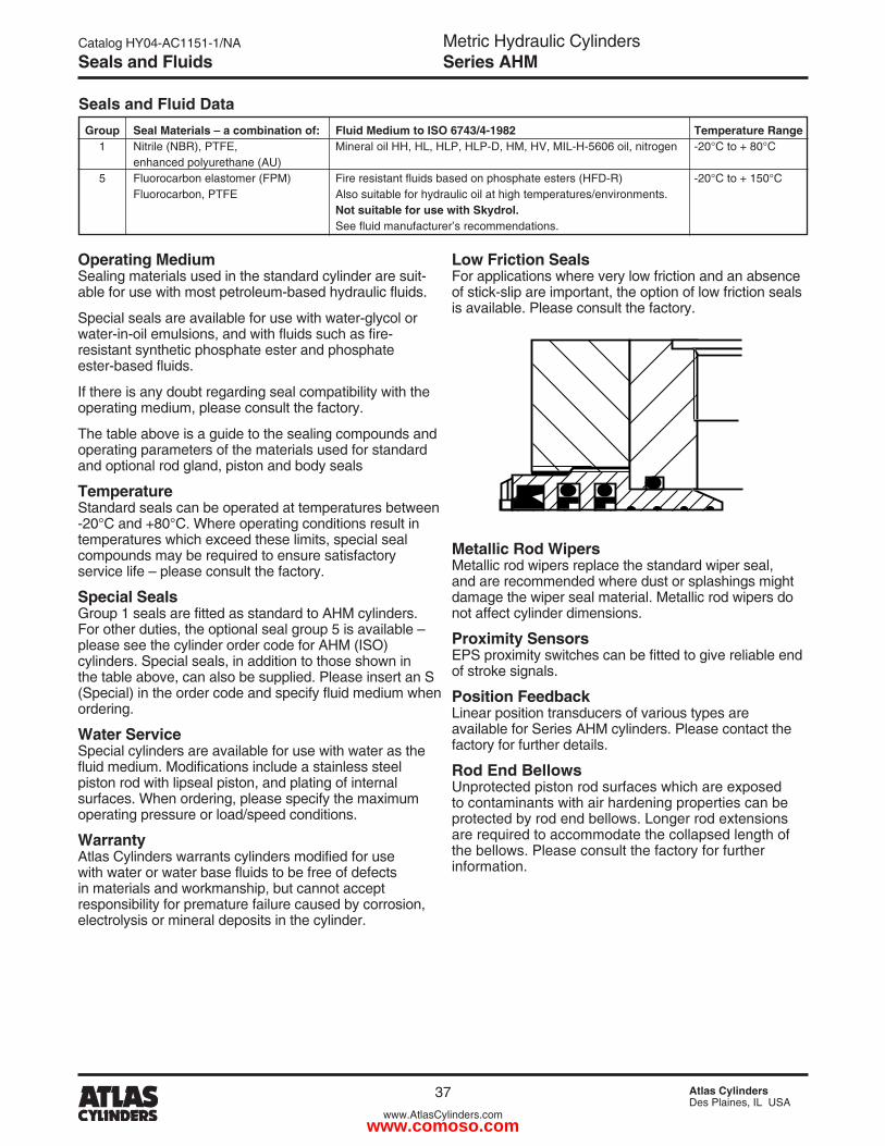
Metric Hydraulic CylindersSeries AHM
Catalog HY04-AC1151-1/NA
37 Atlas CylindersDes Plaines, IL USA
www.AtlasCylinders.com
Seals and Fluids
Seals and Fluid Data
Operating Medium Sealing materials used in the standard cylinder are suit-able for use with most petroleum-based hydraulic fluids.
Special seals are available for use with water-glycol or water-in-oil emulsions, and with fluids such as fire- resistant synthetic phosphate ester and phosphate ester-based fluids.
If there is any doubt regarding seal compatibility with the operating medium, please consult the factory.
The table above is a guide to the sealing compounds and operating parameters of the materials used for standard and optional rod gland, piston and body seals
Temperature Standard seals can be operated at temperatures between -�0°C and +80°C. Where operating conditions result in temperatures which exceed these limits, special seal compounds may be required to ensure satisfactory service life – please consult the factory.
Special Seals Group 1 seals are fitted as standard to AHM cylinders. For other duties, the optional seal group 5 is available – please see the cylinder order code for AHM (ISO) cylinders. Special seals, in addition to those shown in the table above, can also be supplied. Please insert an S (Special) in the order code and specify fluid medium when ordering.
Water Service Special cylinders are available for use with water as the fluid medium. Modifications include a stainless steel piston rod with lipseal piston, and plating of internal surfaces. When ordering, please specify the maximum operating pressure or load/speed conditions.
Warranty Atlas Cylinders warrants cylinders modified for use with water or water base fluids to be free of defects in materials and workmanship, but cannot accept responsibility for premature failure caused by corrosion, electrolysis or mineral deposits in the cylinder.
Metallic Rod Wipers Metallic rod wipers replace the standard wiper seal, and are recommended where dust or splashings might damage the wiper seal material. Metallic rod wipers do not affect cylinder dimensions.
Proximity Sensors EPS proximity switches can be fitted to give reliable end of stroke signals.
Position Feedback Linear position transducers of various types are available for Series AHM cylinders. Please contact the factory for further details.
Rod End Bellows Unprotected piston rod surfaces which are exposed to contaminants with air hardening properties can be protected by rod end bellows. Longer rod extensions are required to accommodate the collapsed length of the bellows. Please consult the factory for further information.
Group1
5
Seal Materials – a combination of:Nitrile (NBR), PTFE,enhanced polyurethane (AU)Fluorocarbon elastomer (FPM)Fluorocarbon, PTFE
Fluid Medium to ISO 6743/4-1982Mineral oil HH, HL, HLP, HLP-D, HM, HV, MIL-H-5606 oil, nitrogen
Fire resistant fluids based on phosphate esters (HFD-R) Also suitable for hydraulic oil at high temperatures/environments.Not suitable for use with Skydrol. See fluid manufacturer’s recommendations.
Temperature Range-�0°C to + 80°C
-�0°C to + 150°C
Low Friction Seals For applications where very low friction and an absence of stick-slip are important, the option of low friction seals is available. Please consult the factory.
www.comoso.com
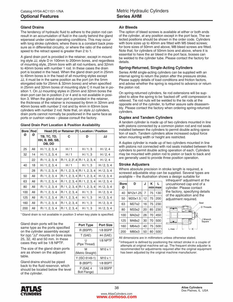
Metric Hydraulic CylindersSeries AHM
Catalog HY04-AC1151-1/NA
38 Atlas CylindersDes Plaines, IL USA
www.AtlasCylinders.com
Optional Features
Gland DrainsThe tendency of hydraulic fluid to adhere to the piston rod can result in an accumulation of fluid in the cavity behind the gland wiperseal under certain operating conditions. This may occur with long stroke cylinders; where there is a constant back pres-sure as in differential circuitry, or where the ratio of the extend speed to the retract speed is greater than � to 1.
A gland drain port is provided in the retainer, except in mount-ing style JJ, style D in 100mm to �00mm bores, and regardless of mounting style, �5mm bore with all rod numbers, and 3�mm to 40mm bores with number 1 rod. In these cases the drain port is located in the head. When the gland drain port in �5mm to 40mm bores is in the head of all mounting styles except JJ, it must be in the same position as the port (on the 5mm elongated side for 25mm & 32mm bores) and when specified in �5mm and 3�mm bores of mounting style C it must be in po-sition 1. On JJ mounting styles in �5mm and 3�mm bores the drain port can be in position � or 4 and is not available in posi-tion 3. When the gland drain port is provided in the retainer, the thickness of the retainer is increased by 6mm in 3�mm and 40mm bores with number � rod and by 4mm in 63mm bore cylinders with number � rod. Note that, on style JJ cylinders, drain ports cannot normally be positioned in the same face as ports or cushion valves – please consult the factory.
Air BleedsThe option of bleed screws is available at either or both ends of the cylinder, at any position except in the port face. The se-lected positions should be shown in the order code. Cylinders with bore sizes up to 40mm are fitted with M5 bleed screws; for bore sizes of 50mm and above, M8 bleed screws are fitted. Note that, for cylinders of 50mm bore and above, where it is essential to have the air bleed in the port face, bosses can be welded to the cylinder tube. Please contact the factory for details.
Spring-Returned, Single-Acting CylindersSeries AHM single-acting cylinders can be supplied with an internal spring to return the piston after the pressure stroke. Please supply details of load conditions and friction factors, and advise whether the spring is required to advance or return the piston rod.
On spring-returned cylinders, tie rod extensions will be sup-plied to allow the spring to be ‘backed off’ until compression is relieved. Tie rod nuts will be welded to the tie rods at the opposite end of the cylinder, to further assure safe disassem-bly. Please contact the factory when ordering spring-returned cylinders.
Duplex and Tandem CylindersA tandem cylinder is made up of two cylinders mounted in line with pistons connected by a common piston rod and rod seals installed between the cylinders to permit double acting opera-tion of each. Tandem cylinders allow increased output force when mounting width or height are restricted.
A duplex cylinder is made up of two cylinders mounted in line with pistons not connected with rod seals installed between the cylinders to permit double acting operation of each. Cylinders may be mounted with piston rod to piston or back to back and are generally used to provide three position operation.
All dimensions are in millimeters unless otherwise stated.� Infrequent is defined by positioning the retract stroke in a couple of attempts at original machine set up. The frequent stroke adjuster is recommended for adjustments required after the original equipment has been adjusted by the original machine manufacturer.
Port Type Port Size R (BSPP) 1/8 BSPP
T (SAE) #4 (SAE)
U 1/8 NPTF (Pipe Thread)
M M10 x 1 (Metric Straight)
Y (ISO 6149-1) M10 x 1
B (BSPT) 1/8 BSPT
P (SAE 4 1/8 BSPP Bolt Flange)
Bore D J K L Ø min max
40 M1�x1.�5 7 75 130
50 M�0x1.5 1� 75 �00
63 M�7x� 16 75 �30
80 M33x� �0 85 �30
100 M4�x� �6 70 450
1�5 M48x� 30 70 500
160 M64x3 40 75 500
�00 M80x3 50 80 500
Stroke AdjustersWhere absolute precision in stroke length is required, a screwed adjustable stop can be supplied. Several types are available – the illustration shows a design suitable for infrequent� adjustment at the uncushioned cap end of a cylinder. Please contact the factory, specifying details of the application and the adjustment required.
Seal
D Threads
L max
J Wrench Square
K
Gland drain ports will be the same type as the ports specified on the cylinder assembly except for non “JJ” mounts on bore sizes �5, 3�, 40 and 50 mm. In these cases they will be 1/8 NPTF.
The size of the gland drain ports are as shown on the adjacent table.
Gland drains should be piped back to the fluid reservoir, which should be located below the level of the cylinder.
Gland Drain Port Location & Position Availability
BoreØ
Rod Ø
Head (H) or Retainer (R) Location / Position
TB, TC, TD, HH, B, BB, SB,
DB, DD
C D JJ
�5 All H / 1, �, 3, 4 H / 1 H / 1, 3 H / �, 4
3� 14 H / 1, �, 3, 4 H / 1 H / 1, 3 H / �, 4
�� R / 1, �, 3, 4 R / 1, �, 31, 4 R / 1, �, 3, 4 H / �, 4
40 18 H / 1, �, 3, 4 H / 1 H / 1, 3 H / �, 3, 4
�8 R / 1, �, 3, 4 R / 1, �, 3, 4 R / 1, �, 3, 4 H / �, 3, 4
50 All R / 1, �, 3, 4 R / 1, �, 3, 4 R / 1, �, 3, 4 H / �, 3, 4
63 All R / 1, �, 3, 4 R / 1, �, 3, 4 R / 1, �, 3, 4 H / �, 3, 4
80 All R / 1, �, 3, 4 R / 1, �, 3, 4 R / 1, �, 3, 4 H / �, 3, 4
100 All R / 1, �, 3, 4 R / 1, �, 3, 4 H / 1, 3 H / �, 3, 4
1�5 All R / 1, �, 3, 4 R / 1, �, 3, 4 H / 1, 3 H / �, 3, 4
160 All R / 1, �, 3, 4 R / 1, �, 3, 4 H / 1, 3 H / �, 3, 4
�00 All R / 1, �, 3, 4 R / 1, �, 3, 4 H / 1, 3 H / �, 3, 41 Gland drain is not available in position 3 when key plate is specified.
www.comoso.com
Metric Hydraulic CylindersSeries AHM
Catalog HY04-AC1151-1/NA
39 Atlas CylindersDes Plaines, IL USA
www.AtlasCylinders.com
Cylinder Safety Guide
Before selecting or using Parker Hannifin Corporation (the Company) cylinders or related accessories, it is important that you read, understand and follow the following safety information. Training is advised before selecting and using the Company’s products.
1.0 General Instructions 1.1 Scope – This safety guide provides instructions for selecting and using
(including assembling, installing, and maintaining) cylinder products. This safety guide is a supplement to and is to be used with the specific Company publications for the specific cylinder products that are being considered for use.
1.2 Fail Safe – Cylinder products can and do fail without warning for many reasons. All systems and equipment should be designed in a fail-safe mode so that if the failure of a cylinder product occurs people and property won’t be endangered.
1.3 Distribution – Provide a free copy of this safety guide to each person responsible for selecting or using cylinder products. Do not select or use the Company’s cylinders without thoroughly reading and understanding this safety guide as well as the specific Company publications for the products considered or selected.
1.4 User Responsibility – Due to very wide variety of cylinder applications and cylinder operating conditions, the Company does not warrant that any particular cylinder is suitable for any specific application. This safety guide does not analyze all technical parameters that must be considered in select-ing a product. The hydraulic and pneumatic cylinders outlined in this catalog are designed to the Company’s design guidelines and do not necessarily meet the design guideline of other agencies such as American Bureau of Shipping, ASME Pressure Vessel Code etc. The user, through its own analysis and testing, is solely responsible for:
• Making the final selection of the cylinders and related accessories. • Determining if the cylinders are required to meet specific design require-
ments as required by the Agency(s) or industry standards covering the design of the user’s equipment.
• Assuring that the user’s requirements are met, OSHA requirements are met, and safety guidelines from the applicable agencies such as but not limited to ANSI are followed and that the use presents no health or safety hazards.
• Providing all appropriate health and safety warnings on the equipment on which the cylinders are used.
1.5 Additional Questions – Call the appropriate Company technical service department if you have any questions or require any additional information. See the Company publication for the product being considered or used, or call 1-847-�98-�400, or go to www.parker.com, for telephone numbers of the appropriate technical service department.
2.0 Cylinder and Accessories Selection 2.1 Seals – Part of the process of selecting a cylinder is the selection of
seal compounds. Before making this selection, consult the “seal information page(s)” of the publication for the series of cylinders of interest.
The application of cylinders may allow fluids such as cutting fluids, wash down fluids etc. to come in contact with the external area of the cylinder. These fluids may attack the piston rod wiper and or the primary seal and must be taken into account when selecting and specifying seal compounds.
Dynamic seals will wear. The rate of wear will depend on many operating factors. Wear can be rapid if a cylinder is mis-aligned or if the cylinder has been improperly serviced. The user must take seal wear into consideration in the application of cylinders.
2.2 Piston Rods – Possible consequences of piston rod failure or separation of the piston rod from the piston include, but are not limited to are:
• Piston rod and or attached load thrown off at high speed. • High velocity fluid discharge. • Piston rod extending when pressure is applied in the piston
retract mode.
Piston rods or machine members attached to the piston rod may move suddenly and without warning as a consequence of other conditions occurring to the machine such as, but not limited to:
• Unexpected detachment of the machine member from the piston rod.
• Failure of the pressurized fluid delivery system (hoses, fittings, valves, pumps, compressors) which maintain cylinder position.
• Catastrophic cylinder seal failure leading to sudden loss of pressurized fluid.
• Failure of the machine control system. Follow the recommendations of the “Piston Rod Selection Chart and Data”
in the publication for the series of cylinders of interest. The suggested piston rod diameter in these charts must be followed in order to avoid piston rod buckling.
Piston rods are not normally designed to absorb bending moments or loads which are perpendicular to the axis of piston rod motion. These additional loads can cause the piston rod to fail. If these types of additional loads are expected to be imposed on the piston rod, their magnitude should be made known to our engineering department.
The cylinder user should always make sure that the piston rod is securely attached to the machine member.
On occasion cylinders are ordered with double rods (a piston rod extended from both ends of the cylinder). In some cases a stop is threaded on to one of the piston rods and used as an external stroke adjuster. On occasions spacers are attached to the machine member connected to the piston rod and also used as a stroke adjuster. In both cases the stops will create a pinch point and the user should consider appropriate use of guards. If these external stops are not perpendicular to the mating contact surface, or if debris is trapped between the contact surfaces, a bending moment will be placed on the piston rod, which can lead to piston rod failure. An external stop will also negate the effect of cushioning and will subject the piston rod to impact loading. Those two (�) conditions can cause piston rod failure. Internal stroke adjusters are available with and without cushions. The use of external stroke adjusters should be reviewed with our engineering department.
The piston rod to piston and the stud to piston rod threaded connections are secured with an anaerobic adhesive. The strength of the adhesive decreases with increasing temperature. Cylinders which can be exposed to tempera-tures above +�50°F (+1�1°C) are to be ordered with a non studded piston rod and a pinned piston to rod joint.
2.3 Cushions – Cushions should be considered for cylinder applications when the piston velocity is expected to be over 4 inches/second.
Cylinder cushions are normally designed to absorb the energy of a linear applied load. A rotating mass has considerably more energy than the same mass moving in a linear mode. Cushioning for a rotating mass application should be review by our engineering department.
2.4 Cylinder Mountings – Some cylinder mounting configurations may have certain limitations such as but not limited to minimum stroke for side or foot mounting cylinders or pressure de-ratings for certain mounts. Carefully review the catalog for these types of restrictions.
Always mount cylinders using the largest possible high tensile alloy steel socket head cap screws that can fit in the cylinder mounting holes and torque them to the manufacturer’s recommendations for their size.
2.5 Port Fittings – Hydraulic cylinders applied with meter out or decelera-tion circuits are subject to intensified pressure at piston rod end.
The rod end pressure is approximately equal to:
operating pressure x effective cap end area effective rod end piston area
Contact your connector supplier for the pressure rating of individual connectors.
3.0 Cylinder and Accessories Installation and Mounting 3.1 Installation 3.1.1 – Cleanliness is an important consideration, and cylinders are
shipped with the ports plugged to protect them from contaminants enter-ing the ports. These plugs should not be removed until the piping is to be installed. Before making the connection to the cylinder ports, piping should be thoroughly cleaned to remove all chips or burrs which might have resulted from threading or flaring operations.
Safety Guide for Selecting and Using Hydraulic, Pneumatic Cylinders and Their Accessories
WARNING: FAILURE OF THE CYLINDER, ITS PARTS, ITS MOUNTING, ITS CONNECTIONS TO OTHER OBJECTS, OR ITS CONTROLS CAN RESULT IN: • Unanticipated or uncontrolled movement of the cylinder or objects connected to it. • Falling of the cylinder or objects held up by it. • Fluid escaping from the cylinder, potentially at high velocity.THESE EVENTS COULD CAUSE DEATH OR PERSONAL INJURY BY, FOR EXAMPLE, PERSONS FALLING FROM HIGH LOCATIONS, BEING CRUSHED OR STRUCK BY HEAVY OR FAST MOVING OBJECTS, BEING PUSHED INTO DANGEROUS EQUIPMENT OR SITUATIONS, OR SLIPPING ON ESCAPED FLUID.
www.comoso.com
Metric Hydraulic CylindersSeries AHM
Catalog HY04-AC1151-1/NA
40 Atlas CylindersDes Plaines, IL USA
www.AtlasCylinders.com
Cylinder Safety Guide
3.1.2 – Cylinders operating in an environment where air drying materials are present such as fast-drying chemicals, paint, or weld splatter, or other hazardous conditions such as excessive heat, should have shields installed to prevent damage to the piston rod and piston rod seals.
3.1.3 – Proper alignment of the cylinder piston rod and its mating component on the machine should be checked in both the extended and retracted positions. Improper alignment will result in excessive rod gland and/or cylinder bore wear. On fixed mounting cylinders attaching the pis-ton rod while the rod is retracted will help in achieving proper alignment.
3.1.4 – Sometimes it may be necessary to rotate the piston rod in order to thread the piston rod into the machine member. This operation must always be done with zero pressure being applied to either side of the piston. Failure to follow this procedure may result in loosening the piston to rod-threaded connection. In some rare cases the turning of the piston rod may rotate a threaded piston rod gland and loosen it from the cylinder head. Confirm that this condition is not occurring. If it does, re-tighten the piston rod gland firmly against the cylinder head.
For double rod cylinders it is also important that when attaching or detaching the piston rod from the machine member that the torque be applied to the piston rod end of the cylinder that is directly attaching to the machine member with the opposite end unrestrained. If the design of the machine is such that only the rod end of the cylinder opposite to where the rod attaches to the machine member can be rotated, consult the factory for further instructions.
3.2 Mounting Recommendations 3.2.1 – Always mount cylinders using the largest possible high tensile
alloy steel socket head screws that can fit in the cylinder mounting holes and torque them to the manufacturer’s recommendations for their size.
3.2.2 – Side-Mounted Cylinders – In addition to the mounting bolts, cylinders of this type should be equipped with thrust keys or dowel pins located so as to resist the major load.
3.2.3 – Tie Rod Mounting – Cylinders with tie rod mountings are recom-mended for applications where mounting space is limited. The standard tie rod extension is shown as BB in dimension tables. Longer or shorter extensions can be supplied. Nuts used for this mounting style should be torqued to the same value as the tie rods for that bore size.
3.2.4 – Flange Mount Cylinders – The controlled diameter of the rod gland extension on head end flange mount cylinders can be used as a pilot to locate the cylinders in relation to the machine. After align-ment has been obtained, the flanges may be drilled for pins or dowels to prevent shifting.
3.2.5 – Trunnion Mountings – Cylinders require lubricated bearing blocks with minimum bearing clearances. Bearing blocks should be carefully aligned and rigidly mounted so the trunnions will not be subjected to bending moments. The rod end should also be pivoted with the pivot pin in line and parallel to axis of the trunnion pins.
3.2.6 – Clevis Mountings – Cylinders should be pivoted at both ends with centerline of pins parallel to each other. After cylinder is mounted, be sure to check to assure that the cylinder is free to swing through its working arc without interference from other machine parts.
4.0 Cylinder and Accessories Maintenance, Troubleshooting and Replacement
4.1 Storage – At times cylinders are delivered before a customer is ready to install them and must be stored for a period of time. When storage is required the following procedures are recommended.
4.1.1 – Store the cylinders in an indoor area which has a dry, clean and noncorrosive atmosphere. Take care to protect the cylinder from both internal corrosion and external damage.
4.1.2 – Whenever possible cylinders should be stored in a vertical posi-tion (piston rod up). This will minimize corrosion due to possible conden-sation which could occur inside the cylinder. This will also minimize seal damage.
4.1.3 – Port protector plugs should be left in the cylinder until the time of installation.
4.1.4 – If a cylinder is stored full of hydraulic fluid, expansion of the fluid due to temperature changes must be considered. Installing a check valve with free flow out of the cylinder is one method.
4.1.5 – When cylinders are mounted on equipment that is stored outside for extended periods, exposed unpainted surfaces, e.g. piston rod, must be coated with a rust-inhibiting compound to prevent corrosion.
4.2 Cylinder Trouble Shooting
4.2.1 – External Leakage 4.2.1.1 – Rod seal leakage can generally be traced to worn or
damaged seals. Examine the piston rod for dents, gouges or score marks, and replace piston rod if surface is rough.
Rod seal leakage could also be traced to gland wear. If clearance is excessive, replace rod bushing and seal. Rod seal leakage can also be traced to seal deterioration. If seals are soft or gummy or brittle, check compatibility of seal material with lubricant used if air cylinder, or operating fluid if hydraulic cylinder. Replace with seal material, which is compatible with these fluids. If the seals are hard or have lost elasticity, it is usually due to exposure to temperatures in excess of 165°F. (+74°C). Shield the cylinder from the heat source to limit temperature to 350°F. (+177°C.) and replace with fluorocarbon seals.
4.2.1.2 – Cylinder body seal leak can generally be traced to loose tie rods. Torque the tie rods to manufacturer’s recommendation for that bore size.
Excessive pressure can also result in cylinder body seal leak. Determine maximum pressure to rated limits. Replace seals and retorque tie rods as in paragraph above. Excessive pressure can also result in cylinder body seal leak. Determine if the pressure rating of the cylinder has been exceeded. If so, bring the operating pressure down to the rating of the cylinder and have the tie rods replaced.
Pinched or extruded cylinder body seal will also result in a leak. Replace cylinder body seal and retorque as in paragraph above.
Cylinder body seal leakage due to loss of radial squeeze which shows up in the form of flat spots or due to wear on the O.D. or I.D. – Either of these are symptoms of normal wear due to high cycle rate or length of service. Replace seals as per paragraph above.
4.2.2 – Internal Leakage 4.2.2.1 – Piston seal leak (by-pass) 1 to 3 cubic inches per minute
leakage is considered normal for piston ring construction. Virtually no static leak with lipseal type seals on piston should be expected. Piston seal wear is a usual cause of piston seal leakage. Replace seals as required.
4.2.2.2 – With lipseal type piston seals excessive back pressure due to over-adjustment of speed control valves could be a direct cause of rapid seal wear. Contamination in a hydraulic system can result in a scored cylinder bore, resulting in rapid seal wear. In either case, replace piston seals as required.
4.2.2.3 – What appears to be piston seal leak, evidenced by the fact that the cylinder drifts, is not always traceable to the piston. To make sure, it is suggested that one side of the cylinder piston be pressurized and the fluid line at the opposite port be disconnected. Observe leakage. If none is evident, seek the cause of cylinder drift in other component parts in the circuit.
4.2.3 – Cylinder Fails to Move the Load 4.2.3.1 – Pneumatic or hydraulic pressure is too low. Check the
pressure at the cylinder to make sure it is to circuit requirements. 4.2.3.2 – Piston Seal Leak – Operate the valve to cycle the cylinder
and observe fluid flow at valve exhaust ports at end of cylinder stroke. Replace piston seals if flow is excessive.
4.2.3.3 – Cylinder is undersized for the load – Replace cylinder with one of a larger bore size.
4.3 Erratic or Chatter Operation 4.3.1 – Excessive friction at rod gland or piston bearing due to load
misalignment – Correct cylinder-to-load alignment. 4.3.2 – Cylinder sized too close to load requirements – Reduce load or
install larger cylinder. 4.3.3 – Erratic operation could be traced to the difference between static
and kinetic friction. Install speed control valves to provide a back pres-sure to control the stroke.
4.4 Cylinder Modifications, Repairs, or Failed Component – Cylinders as shipped from the factory are not to be disassembled and or modified. If cylinders require modifications, these modifications must be done at company locations or by the Company’s certified facilities. The Cylinder Division Engineering Department must be notified in the event of a mechani-cal fracture or permanent deformation of any cylinder component (excluding seals). This includes a broken piston rod, tie rod, mounting accessory or any other cylinder component. The notification should include all operation and application details. This information will be used to provide an engineered repair that will prevent recurrence of the failure.
It is allowed to disassemble cylinders for the purpose of replacing seals or seal assemblies. However, this work must be done by strictly following all the instructions provided with the seal kits.
www.comoso.com
Metric Hydraulic CylindersSeries AHM
Catalog HY04-AC1151-1/NA
41 Atlas CylindersDes Plaines, IL USA
www.AtlasCylinders.com
The items described in this document and other documents or descriptions provided by Parker Hannifin Corporation, its subsidiaries and Divisions (“Com-pany”) and its authorized distributors, are hereby offered for sale at prices to be established by the Company, its subsidiaries and its authorized distributors. This offer and its acceptance by any customer (“Buyer”) shall be governed by all of the following Terms and Conditions. Buyer’s order for any such item, when communicated to the Company, its subsidiary or an authorized distributor (“Seller”) verbally or in writing, shall constitute acceptance of this offer.
1. Terms and Conditions of Sale: All descriptions, quotations, proposals, offers, acknowledgments, acceptances and sales of Seller’s products are subject to and shall be governed exclusively by the terms and conditions stated herein. Buyer’s acceptance of any offer to sell is limited to these terms and conditions. Any terms or conditions in addition to, or inconsistent with those stated herein, proposed by Buyer in any acceptance of an offer by Seller, are hereby objected to. No such additional, different or inconsistent terms and conditions shall become part of the contract between Buyer and Seller unless expressly accepted in writing by Seller. Seller’s acceptance of any offer to purchase by Buyer is expressly conditional upon Buyer’s assent to all the terms and conditions stated herein, including any terms in addition to, or inconsistent with those contained in Buyer’s offer. Acceptance of Seller’s products shall in all events constitute such assent.2. Payment: Payment shall be made by Buyer net 30 days from the date of delivery of the items purchased hereunder. Amounts not timely paid shall bear interest at the maximum rate permitted by law for each month or portion thereof that the Buyer is late in making payment. Any claims by Buyer for omissions or shortages in a shipment shall be waived unless Seller receives notice thereof within 30 days after Buyer’s receipt of the shipment.3. Delivery: Unless otherwise provided on the face hereof, delivery shall be made F.O.B. Seller’s plant. Regardless of the method of delivery, how-ever, risk of loss shall pass to Buyer upon Seller’s delivery to a carrier. Any delivery dates shown are approximate only and Seller shall have no liability for any delays in delivery.4. Warranty: Seller warrants that the items sold hereunder shall be free from defects in material or workmanship for a period of 18 months from date of shipment from the Company. THIS WARRANTY COMPRISES THE SOLE AND ENTIRE WARRANTY PERTAINING TO ITEMS PROVIDED HEREUNDER. SELLER MAKES NO OTHER WARRANTY, GUARANTEE, OR REPRESENTATION OF ANY KIND WHATSOEVER. ALL OTHER WARRANTIES, INCLUDING BUT NOT LIMITED TO, MERCHANTABILITY AND FITNESS FOR PURPOSE, WHETHER EXPRESS, IMPLIED, OR ARISING BY OPERATION OF LAW, TRADE USAGE, OR COURSE OF DEALING ARE HEREBY DISCLAIMED.NOTWITHSTANDING THE FOREGOING, THERE ARE NO WARRAN-TIES WHATSOEVER ON ITEMS BUILT OR ACQUIRED WHOLLY OR PARTIALLY, TO BUYER’S DESIGN OR SPECIFICATIONS.5. Limitation of Remedy: SELLER’S LIABILITY ARISING FROM OR IN ANY WAY CONNECTED WITH THE ITEMS SOLD OR THIS CONTRACT SHALL BE LIMITED EXCLUSIVELY TO REPAIR OR REPLACEMENT OF THE ITEMS SOLD OR REFUND OF THE PURCHASE PRICE PAID BY BUYER, AT SELLER’S SOLE OPTION. IN NO EVENT SHALL SELLER BE LIABLE FOR ANY INCIDENTAL, CONSEQUENTIAL OR SPECIAL DAMAGES OF ANY KIND OR NATURE WHATSOEVER, INCLUDING BUT NOT LIMITED TO LOST PROFITS ARISING FROM OR IN ANY WAY CONNECTED WITH THIS AGREEMENT OR ITEMS SOLD HEREUNDER, WHETHER ALLEGED TO ARISE FROM BREACH OF CONTRACT, EXPRESS OR IMPLIED WARRANTY, OR IN TORT, INCLUDING WITHOUT LIMITATION, NEGLIGENCE, FAILURE TO WARN OR STRICT LIABILITY.6. Changes, Reschedules and Cancellations: Buyer may request to modify the designs or specifications for the items sold hereunder as well as the quantities and delivery dates thereof, or may request to cancel all or part of this order, however, no such requested modification or cancellation shall become part of the contract between Buyer and Seller unless accepted by Seller in a written amendment to this Agreement. Acceptance of any such requested modification or cancellation shall be at Seller’s discretion, and shall be upon such terms and conditions as Seller may require.7. Special Tooling: A tooling charge may be imposed for any special tooling, including without limitations, dies, fixtures, molds and patterns, acquired to manufacture items sold pursuant to this contract. Such special tooling shall be and remain Seller’s property notwithstanding payment of any charges by Buyer. In no event will Buyer acquire any interest in apparatus belonging to Seller which is utilized in the manufacture of the items sold hereunder, even if such apparatus has been specially converted or adapted for such manu-facture and notwithstanding any charges paid by Buyer. Unless otherwise agreed, Seller shall have the right to alter, discard or otherwise dispose of any special tooling or other property in its sole discretion at any time.
8. Buyer’s Property: Any designs, tools, patterns, materials, drawings, confidential information or equipment furnished by Buyer, or any other items which become Buyer’s property, may be considered obsolete and may be destroyed by Seller after two (�) consecutive years have elapsed without Buyer placing an order for the items which are manufactured using such property. Seller shall not be responsible for any loss or damage to such property while it is in Seller’s possession or control.9. Taxes: Unless otherwise indicated on the face hereof, all prices and charges are exclusive of excise, sales, use, property, occupational or like taxes which may be imposed by any taxing authority upon the manufacture, sale or delivery of the items sold hereunder. If any such taxes must be paid by Seller or if Seller is liable for the collection of such tax, the amount thereof shall be in addition to the amounts for the items sold. Buyer agrees to pay all such taxes or to reimburse Seller therefore upon receipt of its invoice. If Buyer claims exemption from any sales, use or other tax imposed by any taxing authority, Buyer shall save Seller harmless from and against any such tax, together with any interest or penalties thereon which may be assessed if the items are held to be taxable.10. Indemnity For Infringement of Intellectual Property Rights: Seller shall have no liability for infringement of any patents, trademarks, copyrights, trade dress, trade secrets or similar rights except as provided in this Part 10. Seller will defend and indemnify Buyer against allegations of infringe-ment of U.S. patents, U.S. trademarks, copyrights, trade dress and trade secrets (hereinafter “Intellectual Property Rights”). Seller will defend at its expense and will pay the cost of any settlement or damages awarded in an action brought against Buyer based on an allegation that an item sold pursuant to this contract infringes the Intellectual Property Rights of a third party. Seller’s obligation to defend and indemnify Buyer is contingent on Buyer notifying Seller within ten (10) days after Buyer becomes aware of such allegations of infringement, and Seller having sole control over the defense of any allegations or actions including all negotiations for settle-ment or compromise. If an item sold hereunder is subject to a claim that it infringes the Intellectual Property Rights of a third party, Seller may, at its sole expense and option, procure for Buyer the right to continue using said item, replace or modify said item so as to make it noninfringing, or offer to accept return of said item and return the purchase price less a reasonable allowance for depreciation. Notwithstanding the foregoing, Seller shall have no liability for claims of infringement based on information provided by Buyer, or directed to items delivered hereunder for which the designs are specified in whole or part by Buyer, or infringements resulting from the modification, combination or use in a system of any item sold hereunder. The foregoing provisions of this Part 10 shall constitute Seller’s sole and exclusive liability and Buyer’s sole and exclusive remedy for infringement of Intellectual Property Rights.If a claim is based on information provided by Buyer or if the design for an item delivered hereunder is specified in whole or in part by Buyer, Buyer shall defend and indemnify Seller for all costs, expenses or judgements resulting from any claim that such item infringes any patent, trademark, copyright, trade dress, trade secret or any similar right.11. Force Majeure: Seller does not assume the risk of and shall not be liable for delay or failure to perform any of Seller’s obligations by reason of circumstances beyond the reasonable control of Seller (hereinafter “Events of Force Majeure”). Events of Force Majeure shall include without limita-tion, accidents, acts of God, strikes or labor disputes, acts, laws, rules or regulations of any government or government agency, fires, floods, delays or failures in delivery of carriers or suppliers, shortages of materials and any other cause beyond Seller’s control.12. Entire Agreement/Governing Law: The terms and conditions set forth herein, together with any amendments, modifications and any different terms or conditions expressly accepted by Seller in writing, shall constitute the entire Agreement concerning the items sold, and there are no oral or other representations or agreements which pertain thereto. This Agree-ment shall be governed in all respects by the law of the State of Ohio. No actions arising out of sale of the items sold hereunder or this Agreement may be brought by either party more than two (�) years after the cause of action accrues.
Offer of Sale
©®�008 Parker Hannifin Corporation Printed in U.S.A. August, �008
Offer of Sale
www.comoso.com

11/08 / Catalog HY04-AC1151-1/NA
Parker Hannifin CorporationAtlas Cylinders500 South Wolf RoadDes Plaines, IL 60016 USAphone (847) �98-�400fax (800) 89�-1008www.AtlasCylinders.com
Parker Hannifin Corporation Motion and Control Division160 Chisholm Drive Milton, ON Canada L9T 3G9 direct (905) 693-3000 fax (905) 876-1958 www.parker.com
www.comoso.com