
Methodology for an Integrated Definition of a System and Its … · 2018-09-25 · Methodology for...
28
1 Methodology for an Integrated Definition of a System and Its Subsystems: The Case-Study of an Airplane and Its Subsystems Sergio Chiesa, Marco Fioriti and Nicole Viola Politecnico di Torino Italy 1. Introduction A modern airplane is without any doubts one of the clearest and most convincing example of “complex system”. A modern airplane consists in fact of various types of elements of different technologies (structures, mechanics, electric, electronics, fluids, etc.). Each element has specific tasks to perform and all elements are harmonically integrated to constitute the whole system. Moreover the airplane is a particularly critical system because of quite obvious safety reasons, because of the relevance of its mission, because of high costs and eventually because of its long Life Cycle. Figure 1 shows an example of a modern transport aircraft. Fig. 1. Alenia C 27 J Let us consider the case of such an airplane, whose mission statement sounds like: “To transport in flight a certain payload from point A to point B”. At a first glance the airplane can be seen as a single entity able to perform a well defined function but, getting more into the details, the airplane appears as consisting of various parts, all harmonically integrated and concurrently working to accomplish the same mission. For instance, taking into account Figure 1, different items, like the wing, the fuselage, the horizontal and vertical tails, the engine nacelles with propellers and the wheels of the landing gear (when the aircraft is on ground), can be easily individuated. By looking at the whole aircraft more into the details, www.intechopen.com
Transcript of Methodology for an Integrated Definition of a System and Its … · 2018-09-25 · Methodology for...
1
Methodology for an Integrated Definition of a System and Its Subsystems:
The Case-Study of an Airplane and Its Subsystems
Sergio Chiesa, Marco Fioriti and Nicole Viola Politecnico di Torino
Italy
1. Introduction
A modern airplane is without any doubts one of the clearest and most convincing example of
“complex system”. A modern airplane consists in fact of various types of elements of different
technologies (structures, mechanics, electric, electronics, fluids, etc.). Each element has specific
tasks to perform and all elements are harmonically integrated to constitute the whole system.
Moreover the airplane is a particularly critical system because of quite obvious safety reasons,
because of the relevance of its mission, because of high costs and eventually because of its long
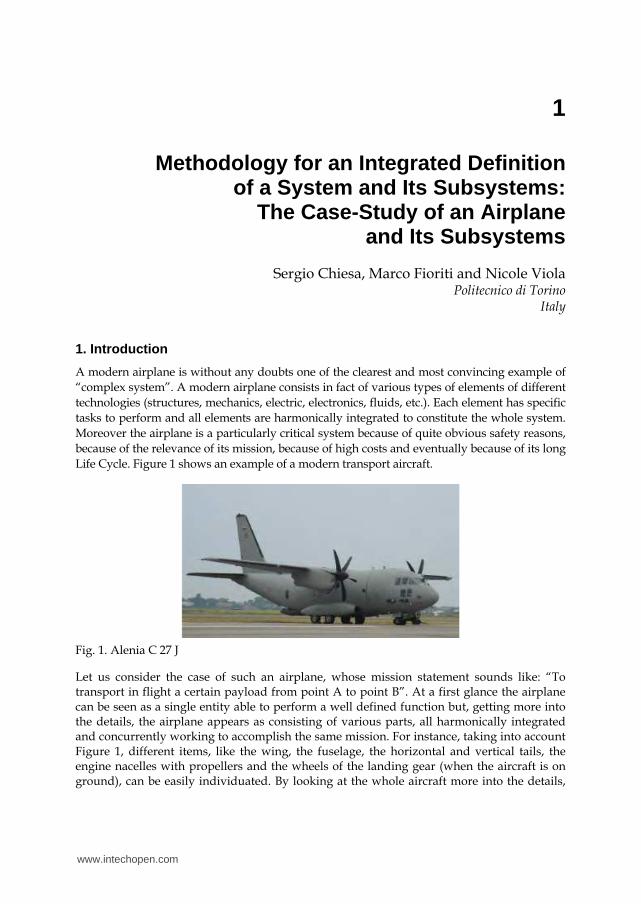
Life Cycle. Figure 1 shows an example of a modern transport aircraft.
Fig. 1. Alenia C 27 J
Let us consider the case of such an airplane, whose mission statement sounds like: “To transport in flight a certain payload from point A to point B”. At a first glance the airplane can be seen as a single entity able to perform a well defined function but, getting more into the details, the airplane appears as consisting of various parts, all harmonically integrated and concurrently working to accomplish the same mission. For instance, taking into account Figure 1, different items, like the wing, the fuselage, the horizontal and vertical tails, the engine nacelles with propellers and the wheels of the landing gear (when the aircraft is on ground), can be easily individuated. By looking at the whole aircraft more into the details,
www.intechopen.com
Systems Engineering – Practice and Theory
14
other items can be identified or at least imagined, like the structural elements, the engines and many mechanical, electronic and fluidic installations, referable to the numerous and various technologies present onboard the aircraft.
1.1 Terminology
Before proceeding any further, it is worth clarifying the terminology related to the so-called “system view” and used in the remainder of the chapter.
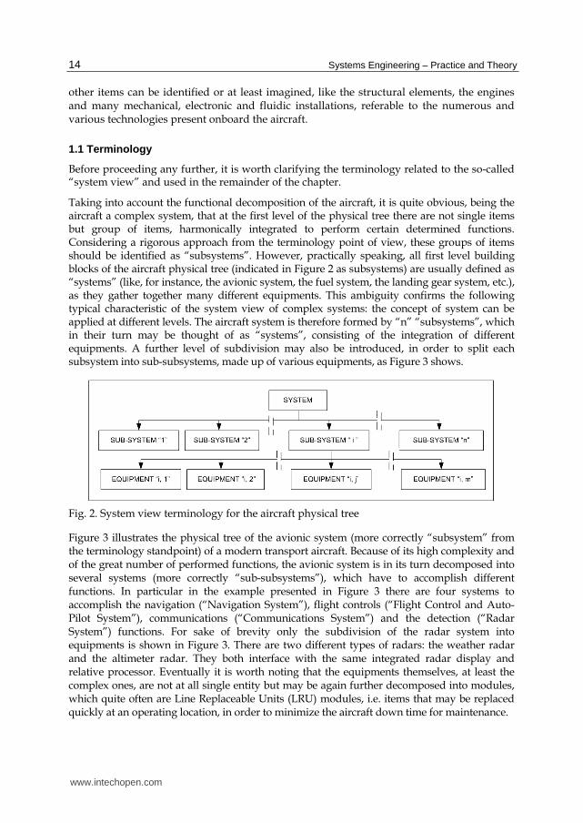
Taking into account the functional decomposition of the aircraft, it is quite obvious, being the aircraft a complex system, that at the first level of the physical tree there are not single items but group of items, harmonically integrated to perform certain determined functions. Considering a rigorous approach from the terminology point of view, these groups of items should be identified as “subsystems”. However, practically speaking, all first level building blocks of the aircraft physical tree (indicated in Figure 2 as subsystems) are usually defined as “systems” (like, for instance, the avionic system, the fuel system, the landing gear system, etc.), as they gather together many different equipments. This ambiguity confirms the following typical characteristic of the system view of complex systems: the concept of system can be applied at different levels. The aircraft system is therefore formed by “n” “subsystems”, which in their turn may be thought of as “systems”, consisting of the integration of different equipments. A further level of subdivision may also be introduced, in order to split each subsystem into sub-subsystems, made up of various equipments, as Figure 3 shows.
Fig. 2. System view terminology for the aircraft physical tree
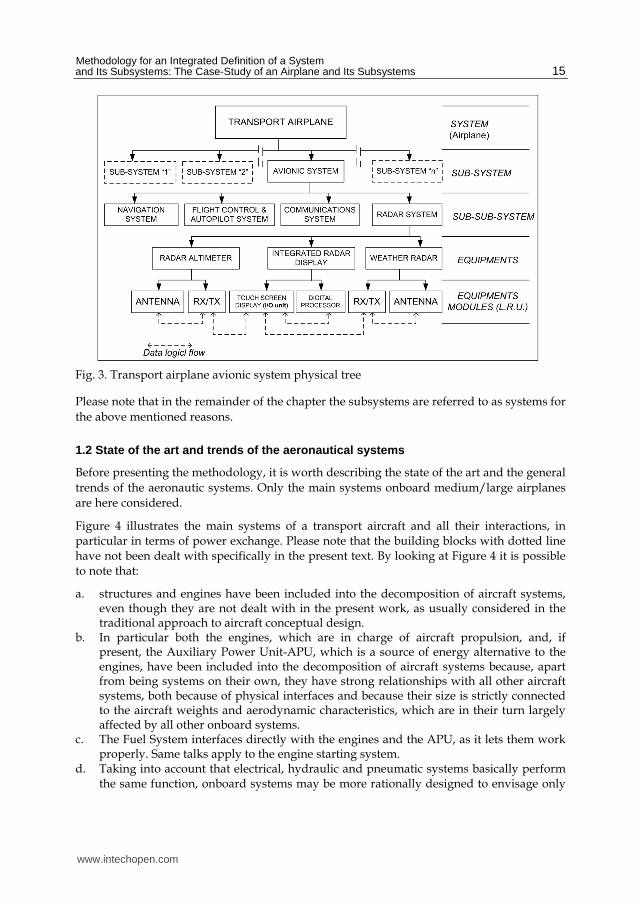
Figure 3 illustrates the physical tree of the avionic system (more correctly “subsystem” from the terminology standpoint) of a modern transport aircraft. Because of its high complexity and of the great number of performed functions, the avionic system is in its turn decomposed into several systems (more correctly “sub-subsystems”), which have to accomplish different functions. In particular in the example presented in Figure 3 there are four systems to accomplish the navigation (“Navigation System”), flight controls (“Flight Control and Auto-Pilot System”), communications (“Communications System”) and the detection (“Radar System”) functions. For sake of brevity only the subdivision of the radar system into equipments is shown in Figure 3. There are two different types of radars: the weather radar and the altimeter radar. They both interface with the same integrated radar display and relative processor. Eventually it is worth noting that the equipments themselves, at least the complex ones, are not at all single entity but may be again further decomposed into modules, which quite often are Line Replaceable Units (LRU) modules, i.e. items that may be replaced quickly at an operating location, in order to minimize the aircraft down time for maintenance.
www.intechopen.com
Methodology for an Integrated Definition of a System and Its Subsystems: The Case-Study of an Airplane and Its Subsystems
15
Fig. 3. Transport airplane avionic system physical tree
Please note that in the remainder of the chapter the subsystems are referred to as systems for
the above mentioned reasons.
1.2 State of the art and trends of the aeronautical systems
Before presenting the methodology, it is worth describing the state of the art and the general
trends of the aeronautic systems. Only the main systems onboard medium/large airplanes
are here considered.
Figure 4 illustrates the main systems of a transport aircraft and all their interactions, in particular in terms of power exchange. Please note that the building blocks with dotted line have not been dealt with specifically in the present text. By looking at Figure 4 it is possible to note that:
a. structures and engines have been included into the decomposition of aircraft systems, even though they are not dealt with in the present work, as usually considered in the traditional approach to aircraft conceptual design.
b. In particular both the engines, which are in charge of aircraft propulsion, and, if present, the Auxiliary Power Unit-APU, which is a source of energy alternative to the engines, have been included into the decomposition of aircraft systems because, apart from being systems on their own, they have strong relationships with all other aircraft systems, both because of physical interfaces and because their size is strictly connected to the aircraft weights and aerodynamic characteristics, which are in their turn largely affected by all other onboard systems.
c. The Fuel System interfaces directly with the engines and the APU, as it lets them work properly. Same talks apply to the engine starting system.
d. Taking into account that electrical, hydraulic and pneumatic systems basically perform the same function, onboard systems may be more rationally designed to envisage only
www.intechopen.com

Systems Engineering – Practice and Theory
16
the electrical system (as onboard the aircraft there are users that can be supplied only with electric power, like lights, electronics, etc.). This solution is represented by the actual successful trend of the so-called “All Electric Aircraft”, which shows quite a few advantages, if compared to the traditional aircraft, in terms of simplicity and rationality. Other intermediate solutions do also exist as the so-called “More Electric Aircraft” testifies, where the engines power is initially transformed only into electric power and then partially into hydraulic and/or pneumatic power.
Fig. 4. Transport airplane system and its (sub-)systems
Table 1 summarizes functions, types and features of the main onboard systems.
SYS FUNCTIONS PERFORMED
SYSTEMS CONFIGURATIONS NOTES
AV
ION
IC S
YS
TE
M
To acquire information (from airplane, from external environment, from other Entities, from Telemetry). To elaborate them. To give them to the Crew, to the airplane, to other Entities by means of Telemetry.
The avionics will be considered at the today state-of-the-art, taking into account usual kinds of equipments. The new trend to “Integrated Modular Avionics” is not considered in a very preliminary approach. The data exchange between Equipments is based on DATA BUS.
www.intechopen.com

Methodology for an Integrated Definition of a System and Its Subsystems: The Case-Study of an Airplane and Its Subsystems
17
SYS FUNCTIONS PERFORMED
SYSTEMS CONFIGURATIONS NOTES
FL
IGH
T C
ON
TR
OL
SY
ST
EM
To modify aerodynamic actions on airplane (by changing its shape), in order to guide and control flight trajectories and to navigate (primary flight controls). To modify aerodynamic characteristics when necessary (secondary flight controls).
The modern flight control system is normally based on digital signal transmission (Fly-By-Wire) and on hydraulic or on electric power (following new trends of All Electric Aircraft). The system design is mainly based on actuator design, considering the possible solutions of hydraulic, electro-hydraulic and electric actuators.
SYS FUNCTIONS PERFORMED
SYSTEMS CONFIGURATIONS NOTES
LA
ND
ING
GE
AR
(N
LG
Ste
erin
g
ML
DG
Wh
ee
ls B
rak
es)
To allow the airplane to move on ground. To support the impact at touch-down. To allow extension and retraction of the system. To steer the nose landing gear. To apply the brake on main landing gear wheels.
Also for this system, after accomplishing the architectural design (to be carefully integrated with the whole aircraft configuration), the typical design activity consists in sizing the actuators. Also in this case the actuators can be hydraulic (that is the state-of-the-art), electro-hydraulic and electric.
SYS FUNCTIONS PERFORMED
SYSTEMS CONFIGURATIONS NOTES
FU
RN
ISH
ING
S
YS
TE
M
To guarantee a pleasant and comfortable journey to the passengers, providing them with all services required.
In a very preliminary approach, all several systems connected to the furnishing system can be simply considered by the point of view of weight and as power users.
www.intechopen.com

Systems Engineering – Practice and Theory
18
SYS FUNCTIONS PERFORMED
SYSTEMS CONFIGURATIONS NOTES
EN
VIR
ON
ME
NT
C
ON
TR
OL
SY
ST
EM
To provide all people onboard the aircraft with correct values of air total pressure, partial O2 pressure and temperature.
Two kinds of CAU can be envisaged: “vapor cycle” and “air cycle”. If the CAU output temperature of the air is < 0°C, it is mandatory to introduce it in the cabin, after mixing with re-circulated cabin air.
SYS FUNCTIONS PERFORMED
SYSTEMS CONFIGURATIONS NOTES
AN
TI-
ICE
SY
ST
EM
To avoid problems due to ice formation of the airplane external surfaces.
The ice problem → increase CD0
→ decrease CLMAX → mobile devices jamming → to perturbe air intake flow → propellers dynamic unbalance
A new kind of anti-ice system on wing leading edge, characterised by very low electric power required, is the
“Impulse System”.
Apart from the anti-ice or de-ice actions illustrated in the figure beside, please consider the electric ice protection of hinges, compensation horn, small sensors, windshields and propellers.
SYS FUNCTIONS PERFORMED
SYSTEMS CONFIGURATIONS NOTES
FU
EL
SY
ST
EM
To perform pressure refuelling, allowing tanks venting. To store onboard all fuel necessary to engines and APU and to feed them when requested.
This system greatly affects aircraft configuration because of the extension and great volumes of its tanks. The booster pumps are usually electrically driven.
www.intechopen.com

Methodology for an Integrated Definition of a System and Its Subsystems: The Case-Study of an Airplane and Its Subsystems
19
SYS FUNCTIONS PERFORMED
SYSTEMS CONFIGURATIONS NOTES
EL
EC
TR
IC S
YS
TE
M
To generate electric power necessary onboard the aircraft. To transform part of it in different forms of electrical current as requested. To feed correctly the users.
The amount of electric power generated onboard the aircraft is more and more increasing. This is particularly true if the electrical system will substitute the hydraulic and the pneumatic system. New forms of electric power (and generators) are now considered. Due to the reversibility characteristic of electric machines, engine starting is also considered.
SYS FUNCTIONS PERFORMED
SYSTEMS CONFIGURATIONS NOTES
PN
EU
MA
TIC
SY
ST
EM
To generate pneumatic power necessary onboard the aircraft. To feed correctly the users.
The bleed air from engines and APU is the state of the art of pneumatic power and it is particularly useful, if the air has to be introduced in pressurized cabins. To avoid engine’s penalties, electric driven compressors can also be adopted.
SYS FUNCTIONS PERFORMED
SYSTEMS CONFIGURATIONS NOTES
HY
DR
AU
LIC
SY
ST
EM
To generate hydraulic power necessary onboard the aircraft. To feed correctly the users (actuators).
Hydraulic power is the state of the art form of power used to feed actuators. Electric actuators as well as hydraulic system supplied by electric motor driven pumps can be considered a valuable alternative to the conventional hydraulic system with engine driven pumps.
Table 1. Functions, types and features of the main onboard systems
www.intechopen.com

Systems Engineering – Practice and Theory
20
2. Airplane system design
As already said, an airplane is a complex system, consisting of many different elements all harmonically integrated to form a unique entity, designed to perform a well defined mission.
Let us now examine the complex process, which, starting from the customer needs and moving on to the definition of requirements, proceeds with the development and then the manufacturing of the new airplane. Figure 5 schematically illustrates this complex process. Considering a reference frame with time on the x-axis and the level of details on the y-axis, it can be noted that, starting from the customer needs, the new product is first defined at system level, then at subsystem level and eventually, getting more into the details of the design flow, at equipment level. Every successive step, which corresponds to a new design phase, is an iterative process (see Figure 5) and the results of each phase are seriously affected by those of the previous phase. If we look at Figure 5, we can therefore understand that, starting from the customer needs and then the requirements definition, the process gets through all design phases (from the conceptual to the preliminary and eventually to the detailed design) following a typical top-down approach with an increased level of details from the system to the equipments. Then, once equipments have been defined and thus bought and/or manufactured, they are tested and integrated to form first the subsystems and eventually the whole system through the final assembly, according to a typical bottom-up approach. Once the final assembly has been completed, new activities at system level can be performed. After successfully accomplishing these activities, i.e. the system functional testing, the operative life of the new product can begin.
Fig. 5. The system design process
2.1 Airplane conceptual design
Taking into account the whole design process presented in Figure 5, it is quite clear that the main criticality of the conceptual design phase lies in the capability of generating (Antona et al., 2009) a first idea of the new product. A first idea of the future product implies:
a. architectural choices, i.e. definition of the global product’s architecture in terms of shape and type of main elements and mutual location of the elements themselves. It is worth noting that the various alternatives can generate quite a few combinations, which are all potentially feasible and which shall then be traded to pick up the best ones. For sake of clarity, let us consider a modern medium passenger transport airplane. The possible alternatives for its architectural layout may be expressed in terms of:
www.intechopen.com
Methodology for an Integrated Definition of a System and Its Subsystems: The Case-Study of an Airplane and Its Subsystems
21
engines type: for instance state-of-the-art turbo-fan with high by-pass ratio and innovative turbo-fan with very high by-pass ratio;
engines number: for instance two engines with high thrust or four engines with lower thrust;
engines position: for instance located in nacelles directly attached to the underside of the wing or aft mounted;
definition of all envisaged systems, without getting into the details of any of them. b. quantitative choices, i.e. preliminary (please note that in aerospace field approximation
even at this stage shall not exceed 10%-15% of the final value) definition of the most relevant characteristics of the future product, like, for instance, size, weight and performances. At this level of the design process the future product is thus addressed as a unique system. As far as its subsystems are concerned, they are just envisaged but not yet sized at this stage, even though their weight may be already estimated as percentage of the system empty weight, according to a typical top-down approach.
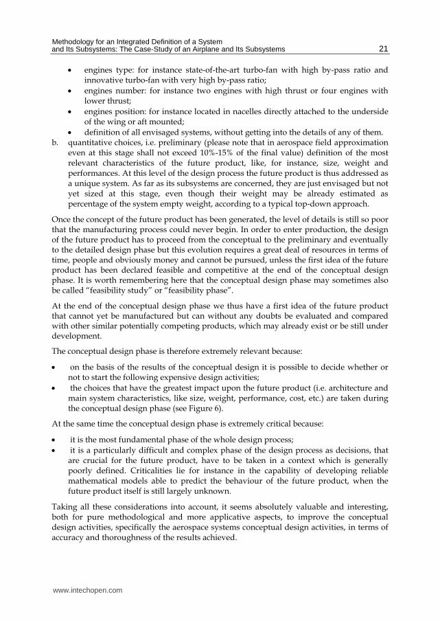
Once the concept of the future product has been generated, the level of details is still so poor that the manufacturing process could never begin. In order to enter production, the design of the future product has to proceed from the conceptual to the preliminary and eventually to the detailed design phase but this evolution requires a great deal of resources in terms of time, people and obviously money and cannot be pursued, unless the first idea of the future product has been declared feasible and competitive at the end of the conceptual design phase. It is worth remembering here that the conceptual design phase may sometimes also be called “feasibility study” or “feasibility phase”.
At the end of the conceptual design phase we thus have a first idea of the future product that cannot yet be manufactured but can without any doubts be evaluated and compared with other similar potentially competing products, which may already exist or be still under development.
The conceptual design phase is therefore extremely relevant because:
on the basis of the results of the conceptual design it is possible to decide whether or not to start the following expensive design activities;
the choices that have the greatest impact upon the future product (i.e. architecture and main system characteristics, like size, weight, performance, cost, etc.) are taken during the conceptual design phase (see Figure 6).
At the same time the conceptual design phase is extremely critical because:
it is the most fundamental phase of the whole design process;
it is a particularly difficult and complex phase of the design process as decisions, that are crucial for the future product, have to be taken in a context which is generally poorly defined. Criticalities lie for instance in the capability of developing reliable mathematical models able to predict the behaviour of the future product, when the future product itself is still largely unknown.
Taking all these considerations into account, it seems absolutely valuable and interesting, both for pure methodological and more applicative aspects, to improve the conceptual design activities, specifically the aerospace systems conceptual design activities, in terms of accuracy and thoroughness of the results achieved.
www.intechopen.com

Systems Engineering – Practice and Theory
22
Fig. 6. Conceptual design relevance
2.2 Airplane systems conceptual design
Unlike the past, when the system view of the airplane was not at all evident and the results of the conceptual design were almost exclusively turned to the preliminary definition of the airplane main characteristics, today the systems engineering approach is widely accepted and appreciated and the results of the conceptual design include also initial basic choices for onboard systems. Please note that these initial choices for the onboard systems lay the groundwork for the next activities of systems development during the successive design phases, as shown in Figure 5. It is quite obvious that the capability of preliminary defining onboard systems already during the conceptual design phase implies more accurate and detailed results of the conceptual design itself. The initial definition of the onboard systems allows in fact achieving a more precise and reliable estimation of the whole system characteristics (like, for instance, the system empty weight, given by the sum of the onboard systems weights) and make the start of the successive preliminary design activities easier. However it is clear that more accurate and detailed results require a more complex conceptual design phase, which can be successfully faced today thanks to computer programs automation and to new powerful software tools.
Figure 7 schematically illustrates the main steps of conceptual design according to the traditional approach (airplane conceptual design) and to the proposed innovative approach (airplane & systems conceptual design).
As Figure 7 shows, the traditional approach to conceptual design envisages both architectural and quantitative choices, mutually interrelated, to generate the first idea of the future product (see also sub-section 2.1). According to this approach in conceptual design there are just the individuation of the onboard systems of the future product and the estimation of their weights. Unlike the traditional approach, the innovative approach, besides the architectural and quantitative choices, envisages also the preliminary definition of onboard systems, once the systems themselves have been individuated. For every onboard system, the preliminary definition implies:
choice of systems architecture through block diagrams at main equipments level; initial sizing of such blocks, in terms of weight, volume and power required, on the basis of their performance requirements, in order to be able to start selecting them; preliminary studies of equipments and systems installation onboard the airplane, on the basis of main equipments weight and volume considerations. These preliminary studies on systems installation allow making more accurate estimation on the airplane mass properties;
www.intechopen.com

Methodology for an Integrated Definition of a System and Its Subsystems: The Case-Study of an Airplane and Its Subsystems
23
evaluation of mass and power budgets on the basis of weight and power required of each system equipment.
Fig. 7. Main steps of conceptual design according to the traditional and the innovative approach
Drawing some conclusions, we can say that, as the proposed new approach guarantees more accurate and detailed results and as the problem has not been extensively addressed so far (unlike what has happened in other disciplines, like, for instance, structures, aerodynamics and flight mechanics, whose mathematical algorithms have been integrated in a Multi Disciplinary Optimization, MDO, context in conceptual design), the development of a conceptual design methodology that pursues the new approach (see right hand side of Figure 7) appears extremely useful and valuable. ASTRID (Aircraft on board Systems Sizing And TRade-Off Analysis in Initial Design phase) is the acronyms of the innovative conceptual design methodology, proposed by the Authors. ASTRID is based on a dedicated software tool to easily perform iterations and successive refinements and to make the evaluation and comparison of various potentially feasible alternatives possible. ASTRID will be the main topic of the next section.
3. Airplane system innovative conceptual design methodology
Main features of the proposed new conceptual design methodology for the airplane system are the early investigation of avionics and onboard general systems and their integration with the traditional activities of conceptual design, i.e. the definition of system architecture and the accomplishment of system sizing, in terms of weight, volume, performances and system cost estimation. However, unlike the traditional approach to preliminary system sizing, avionics and onboard general systems, cannot be easily assessed through few and
www.intechopen.com

Systems Engineering – Practice and Theory
24
simple relationships. It is worth remembering here that, according to the traditional approach, the study of avionics and onboard general systems starts only after at least a preliminary concept of aircraft has been defined. The conventional sequence of design activities, characterized by aircraft conceptual design and then avionics and onboard general systems preliminary assessment, is still the current state-of-the-art, like a considerable number of valuable references, such as Daniel P. Raymer (Raymer, 1992) and Jan Roskam (Roskam, 1990), testifies. The same approach is pursued by two important software tools of aircraft design, RDS – “Integrated aircraft design and analysis” (by Conceptual Research Corporation, a company founded and lead by Daniel Raymer) and AAA – “Advanced Aircraft Analysis” (by DAR Corporation, founded by Jan Roskam), which have been developed on the basis of the works of, respectively, Daniel P. Raymer and Jan Roskam and have recently become widespread also at industrial level. The relevance of avionics and onboard general systems in aircraft conceptual design is witnessed by John Fielding from Cranfield College of Aeronautics (Fielding, 1999), who dedicates a great effort to the description of avionics and onboard general systems, but, as his work provides the reader with just an introduction to aircraft design issues, no specific methodology is reported in the text. On the basis of this preliminary assessment, the development of ASTRID seems to be highly desirable, in order to support the design process of new aircraft.
3.1 General context, goals and overview of ASTRID methodology
Before proceeding any further, let us briefly review the most common and widely used methodologies of aircraft conceptual design, focusing in particular on the way in which avionics and onboard general systems are taken into account. There are two main types of approaches:
methodologies in which the aircraft Maximum Take-off Gross Weight (MTGW) is defined in such a way to match requirements (generally expressed in terms of performances) and it is broken down into pay-load, fuel and empty weight, being the empty weight often defined as a percentage of MTGW itself;
methodologies in which the aircraft MTGW is estimated on the basis of requirements (for example the fuel weight depends on the range requirement) and the components of the empty weight are estimated on the basis of the Weight Estimation Relationships (WERs).
It can be noticed that in the first case every considerations about avionics and onboard general systems is postponed to a later stage of the design process, where, apart from all other requirements, avionics and onboard general systems shall be compliant with the previously defined constraint of global weight. Unlike the first case, in the second type of methodologies avionics and onboard general systems are taken into account since the very beginning of the design process at least from the point of view of weight, as their weight is established as part of the empty weight, either as percentage (in simplified methodologies) or as a result of WERs for the various systems (Staton, 1972) (Chiesa et al., 2000). It is interesting to observe that, on the basis of WERs for a single system, the same number of CERs (Cost Estimation Relationships) have been derived by several authors (Beltramo et al., 1979). Only in the second type of methodologies of aircraft conceptual design, some influences of avionics and onboard general systems on the overall aircraft design can therefore be expected since the very beginning of the design process, as the WERs of the
www.intechopen.com
Methodology for an Integrated Definition of a System and Its Subsystems: The Case-Study of an Airplane and Its Subsystems
25
various systems allow defining some crucial parameters of the systems themselves, like the number of fuel tanks of the fuel system, the number of actuators of the flight control system, the electric power that has to be supplied by the energy sources, etc.. Nevertheless other considerations on the following issues are still missing:
performances of the systems and their capability of satisfying the requirements for the definition of the new aircraft;
volume required by the systems and their installation onboard the aircraft, with the consequent influence on all other mass properties other than weight.
After reviewing the various existing methodologies of aircraft conceptual design, the main
characteristics of the new methodology can be brought to evidence. Referring in particular
to the influence of avionics and onboard general systems on the conceptual design of the
whole aircraft, the new methodology envisages taking into account the design of avionics
and onboard general systems since the very beginning of the design process through
various successive refinements and iterations that affect also the main aircraft
characteristics. The new tool shall not therefore be structured at level of the single systems
(for example as ATA subdivision) but, for each system, at level of its main equipments (i.e.,
for instance, in the avionic system: weather radar, AHRS, ADC, VOR, radio UHF, etc.; in the
electrical system: generators, TRUs, inverters, batteries, etc.). Thanks to this approach four
main advantages that may lead to a better definition of the whole aircraft very early during
the design process can be envisaged:
1. possibility of defining the various systems architectures, even if simplified, very early during the design process;
2. possibility of achieving a reasonable confidence of the capability of the systems to perform their assigned functions;
3. capability of carrying out installation study very early during the design process, thus being able to estimate the influences on the centre of gravity position and moments of inertia;
4. capability of preliminarily estimating safety and reliability and performing an initial assessment of maintainability/accessibility with optimization of the turn-around operations (Chiesa, 2007).
Focusing the attention on main equipments, by estimating their weights and costs, might
lead to neglect the contribution to the overall weight and cost of the remaining parts of the
systems, such as small components, like lines, pipes, wires, installation devices, etc.
However the problem can be solved by means of a further estimate of these small
components and/or by matching weight and cost estimations at main
equipment/components level with results obtained by WERs and CERs at system level.
Before getting into the details of the logical steps that have to be taken to apply ASTRID
methodology, a synthetic overview of the complete methodology is reported hereafter.
After preliminary estimating the aircraft global parameters, the main equipments of each system can be identified through, for example, the functional analysis, keeping in mind the various possible alternatives of architectures and taking into account the new emerging technologies. After the identification of the main equipments of each system and their interfaces, the inputs and outputs of each building block (i.e. main equipment) can be
www.intechopen.com
Systems Engineering – Practice and Theory
26
individuated. Specifically per each building block the number of inputs/outputs as well as which parameters have to be considered as inputs/outputs have to be established. It is quite obvious that the aircraft data, the design constraints (including the constraints of regulations) and the performance requirements, that characterize the equipments, are among the considered parameters, which on a statistical basis allow then to estimate the weight, volume, cost and any other possible feature of the equipment itself. Starting from the inputs/outputs of every main equipment, the relationships that allow calculating the value of the outputs on the basis of the inputs can then be defined through statistical relationships.
Notwithstanding the integration between the various systems, each system has to be considered at least initially separately for the identification of its main equipment. It appears therefore obvious that, in this phase, a logical sequence with which the tool addresses the various systems has to be established. In order to avoid or minimize iterations, for instance, the systems requiring power supply have to be considered first and later on those generating power.
Once the complete set of relationships between inputs and outputs of each main equipment and their sequence, which constitute a mathematical model, has been established, the design process proceeds with the application of the iterative loops for the refinement of the aircraft sizing and performance estimation.
The output of the convergence of this iterative loop is an optimized aircraft with optimized avionics and on-board general systems architecture.
3.2 ASTRID methodology
Purpose of the section is to describe in an easy and straightforward way the various steps that have to be taken to apply ASTRID methodology and the logical path that has to be followed to move from one step to the next one.
Figure 8 shows the flowchart of the complete methodology.
Main goal of the methodology is to identify the best global configuration, in terms of architecture and system sizing, of avionics and onboard general systems for a defined airplane concept, which may be either already frozen or still under development. It is worth noting that the former case implies more constraints with respect to the latter case for the avionics and onboard systems design. Moreover in the latter case the global aircraft design can still benefit from the data coming from the avionics and onboard systems design, in order to achieve a more accurate global conceptual design.
ASTRID is therefore a separate module that can however be integrated with the global aircraft concept definition thanks to specific building blocks dedicated to data exchange.
The methodology is characterized by the possibility of carrying out more designs of avionics and onboard general systems for the same aircraft concept, in order to trade then off the various designs and pick up the best ones. The methodology also allows addressing only some systems, in case others have still been designed.
Main expected result of every system module is the definition of the system architecture and
the accomplishment of the system sizing at equipments level, with obvious advantages in
www.intechopen.com

Methodology for an Integrated Definition of a System and Its Subsystems: The Case-Study of an Airplane and Its Subsystems
27
terms of estimation of aircraft mass and power budgets. Per each system, it is also possible,
if requested, to study the system installation onboard the aircraft at equipments level, with
clear advantages in terms global aircraft mass properties and evaluation of the feasibility of
the aircraft configuration itself.
Fig. 8. ASTRID methodology flow-chart
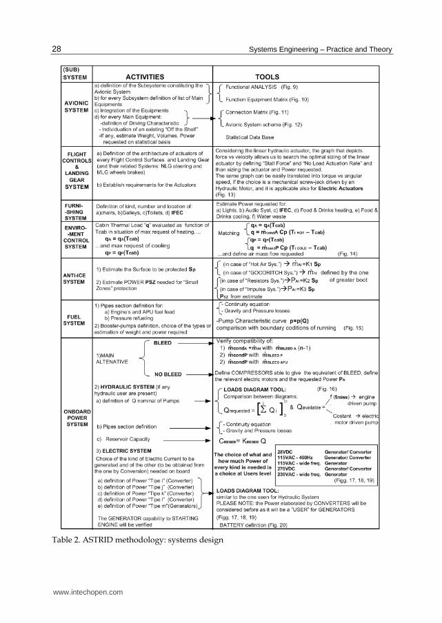
Taking now into account avionics and onboard general systems, Table 2 sums up the
activities to perform and the tools/algorithms to apply, in order to accomplish the design of
each system.
www.intechopen.com
Systems Engineering – Practice and Theory
28
Table 2. ASTRID methodology: systems design
www.intechopen.com
Methodology for an Integrated Definition of a System and Its Subsystems: The Case-Study of an Airplane and Its Subsystems
29
Considering each system separately, the following considerations need to be highlighted:
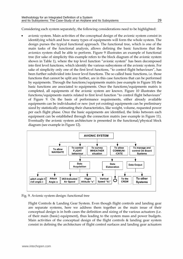
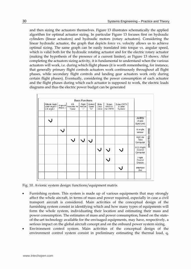
avionic system. Main activities of the conceptual design of the avionic system consist in identifying which and how many types of equipments will form the whole system. The design purses the typical functional approach. The functional tree, which is one of the main tasks of the functional analysis, allows defining the basic functions that the avionics system shall be able to perform. Figure 9 illustrates an example of functional tree (for sake of simplicity this example refers to the block diagram of the avionic system shown in Table 1), where the top level function “avionic system” has been decomposed into first level functions, which identify the various subsystems of the avionic system. For sake of simplicity only one of the first level functions, “to control flight behaviours”, has been further subdivided into lower level functions. The so called basic functions, i.e. those functions that cannot be split any further, are in this case functions that can be performed by equipments. Through the functions/equipments matrix (see example in Figure 10) the basic functions are associated to equipments. Once the functions/equipments matrix is completed, all equipments of the avionic system are known. Figure 10 illustrates the functions/equipments matrix related to first level function “to control flight behaviours” of Figure 9. On the basis of performance requirements, either already available equipments can be individuated or new (not yet existing) equipments can be preliminary sized by statistically estimating their characteristics, like weight, volume, requested power per each flight phase. Once the basic equipments are identified, the links between each equipment can be established through the connection matrix (see example in Figure 11). Eventually the avionic system architecture is presented in the functional/physical block diagram (see example in Figure 12).
Fig. 9. Avionic system design: functional tree
Flight Controls & Landing Gear System. Even though flight controls and landing gear are separate systems, here we address them together as the main issue of their conceptual design is in both cases the definition and sizing of the various actuators (i.e. of their main (basic) equipment), thus leading to the system mass and power budgets. Main activities of the conceptual design of the flight controls & landing gear system consist in defining the architecture of flight control surfaces and landing gear actuators
www.intechopen.com
Systems Engineering – Practice and Theory
30
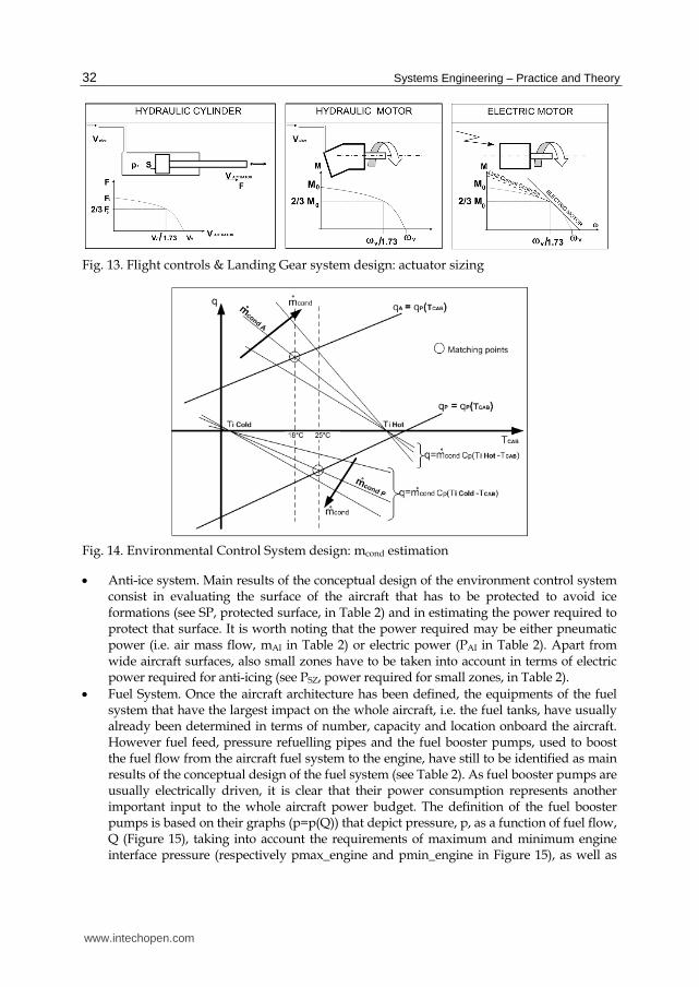
and then sizing the actuators themselves. Figure 13 illustrates schematically the applied algorithm for optimal actuator sizing. In particular Figure 13 focuses first on hydraulic cylinders (linear actuators) and hydraulic motors (rotary actuators). Considering the linear hydraulic actuator, the graph that depicts force vs. velocity allows us to achieve optimal sizing. The same graph can be easily translated into torque vs. angular speed, which is valid both for the hydraulic rotating actuator and for the electric rotary actuator (making the hypothesis of the presence of a current limiter), as Figure 13 shows. After completing the actuators sizing activity, it is fundamental to understand when the various actuators will work, i.e. during which flight phases (it is worth remembering, for instance, that generally primary flight controls actuators work continuously throughout all flight phases, while secondary flight controls and landing gear actuators work only during certain flight phases). Eventually, considering the power consumption of each actuator and the flight phases during which each actuator is supposed to work, the electric loads diagrams and thus the electric power budget can be generated
Fig. 10. Avionic system design: functions/equipment matrix
Furnishing system. This system is made up of various equipments that may strongly affect the whole aircraft, in terms of mass and power required, especially in case a civil transport aircraft is considered. Main activities of the conceptual design of the furnishing system consist in identifying which and how many types of equipments will form the whole system, individuating their location and estimating their mass and power consumption. The estimates of mass and power consumption, based on the state-of-the-art technology available for the envisaged equipments, may have, respectively, a serious impact on the global aircraft concept and on the onboard power system sizing.
Environment control system. Main activities of the conceptual design of the environment control system consist in preliminary estimating the thermal load, q,
www.intechopen.com

Methodology for an Integrated Definition of a System and Its Subsystems: The Case-Study of an Airplane and Its Subsystems
31
between the cabin and the external environment, and then the required air mass flow, mcond, to keep the temperature of the cabin within an acceptable range of values (usually between 18°C and 25°C). After estimating the thermal load, the required air mass flow can be computed, depending on the desired temperature inside the cabin, TCAB, and on different operative scenarios, which range between the so-called cold case (case A in Table 2), when maximum heating is required, and the so-called hot case (case P in Table 2), when maximum cooling is required. The air mass flow, that can be provided at different temperatures (for instance, at high temperature, TI HOT, in cold cases or at low temperature, TI COLD, in hot cases), can in fact be computed by matching the two equations, which express the thermal load qA or qP in Table 2 and in Figure 14 and the heat load provided by the system (q in Figure 14) to maintain the desired temperature inside the cabin.
Fig. 11. Avionic system design: connection matrix
Fig. 12. Avionic system design: functional/physical block diagram
www.intechopen.com
Systems Engineering – Practice and Theory
32
Fig. 13. Flight controls & Landing Gear system design: actuator sizing
Fig. 14. Environmental Control System design: mcond estimation
Anti-ice system. Main results of the conceptual design of the environment control system consist in evaluating the surface of the aircraft that has to be protected to avoid ice formations (see SP, protected surface, in Table 2) and in estimating the power required to protect that surface. It is worth noting that the power required may be either pneumatic power (i.e. air mass flow, mAI in Table 2) or electric power (PAI in Table 2). Apart from wide aircraft surfaces, also small zones have to be taken into account in terms of electric power required for anti-icing (see PSZ, power required for small zones, in Table 2).
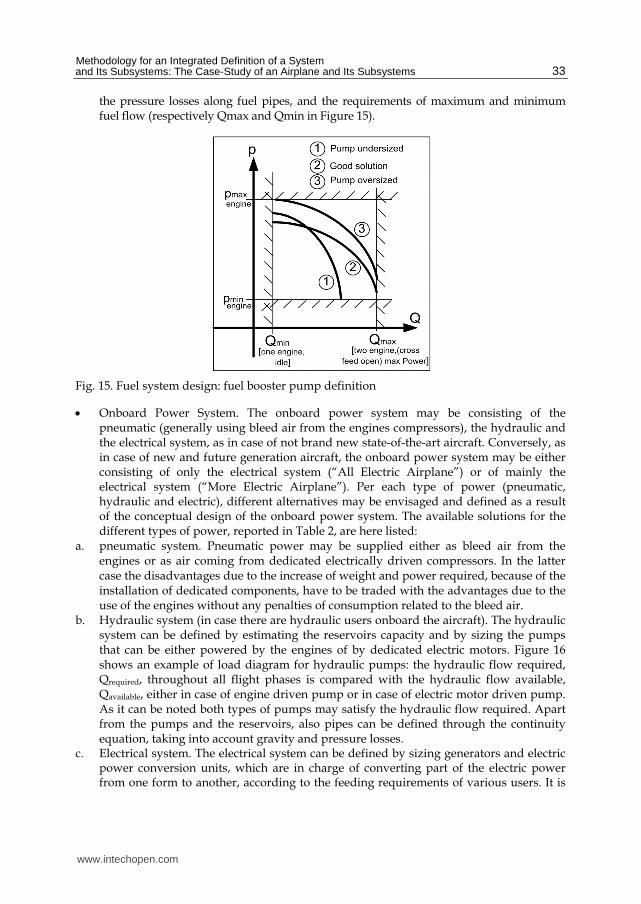
Fuel System. Once the aircraft architecture has been defined, the equipments of the fuel system that have the largest impact on the whole aircraft, i.e. the fuel tanks, have usually already been determined in terms of number, capacity and location onboard the aircraft. However fuel feed, pressure refuelling pipes and the fuel booster pumps, used to boost the fuel flow from the aircraft fuel system to the engine, have still to be identified as main results of the conceptual design of the fuel system (see Table 2). As fuel booster pumps are usually electrically driven, it is clear that their power consumption represents another important input to the whole aircraft power budget. The definition of the fuel booster pumps is based on their graphs (p=p(Q)) that depict pressure, p, as a function of fuel flow, Q (Figure 15), taking into account the requirements of maximum and minimum engine interface pressure (respectively pmax_engine and pmin_engine in Figure 15), as well as
www.intechopen.com
Methodology for an Integrated Definition of a System and Its Subsystems: The Case-Study of an Airplane and Its Subsystems
33
the pressure losses along fuel pipes, and the requirements of maximum and minimum fuel flow (respectively Qmax and Qmin in Figure 15).
Fig. 15. Fuel system design: fuel booster pump definition
Onboard Power System. The onboard power system may be consisting of the pneumatic (generally using bleed air from the engines compressors), the hydraulic and the electrical system, as in case of not brand new state-of-the-art aircraft. Conversely, as in case of new and future generation aircraft, the onboard power system may be either consisting of only the electrical system (“All Electric Airplane”) or of mainly the electrical system (“More Electric Airplane”). Per each type of power (pneumatic, hydraulic and electric), different alternatives may be envisaged and defined as a result of the conceptual design of the onboard power system. The available solutions for the different types of power, reported in Table 2, are here listed:
a. pneumatic system. Pneumatic power may be supplied either as bleed air from the engines or as air coming from dedicated electrically driven compressors. In the latter case the disadvantages due to the increase of weight and power required, because of the installation of dedicated components, have to be traded with the advantages due to the use of the engines without any penalties of consumption related to the bleed air.
b. Hydraulic system (in case there are hydraulic users onboard the aircraft). The hydraulic system can be defined by estimating the reservoirs capacity and by sizing the pumps that can be either powered by the engines of by dedicated electric motors. Figure 16 shows an example of load diagram for hydraulic pumps: the hydraulic flow required, Qrequired, throughout all flight phases is compared with the hydraulic flow available, Qavailable, either in case of engine driven pump or in case of electric motor driven pump. As it can be noted both types of pumps may satisfy the hydraulic flow required. Apart from the pumps and the reservoirs, also pipes can be defined through the continuity equation, taking into account gravity and pressure losses.
c. Electrical system. The electrical system can be defined by sizing generators and electric power conversion units, which are in charge of converting part of the electric power from one form to another, according to the feeding requirements of various users. It is
www.intechopen.com

Systems Engineering – Practice and Theory
34
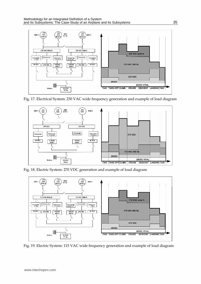
worth underling the importance of developing different solutions in terms of users and therefore generators, in order to be able to compare then these alternatives and pick up the best one. It has to be remembered that different forms of electric power imply different weight and cost. Among the various available solutions, the most common trend is to select the option that generates the type of power to feed the greatest number of users, in order to minimize the request of power conversion. As reported in Table 2, various solutions are available. The most common ones are listed hereafter: i. 115 VAC 400 Hz generation and conversion of part of the electric power to 28 VDC; ii. 115 VAC wide frequency generation and conversion of part of the electric power to
115 VAC 400 Hz, 270 VDC and 28 VDC; iii. 270 VDC generation and conversion of part of the electric power to 115 VAC 400
Hz and 28 VDC; iv. 230 VAC wide frequency generation and conversion of part of the electric power to
115 VAC 400 Hz, 270 VDC and 28 VDC. While the first case is the today most common solution, the other three options represent the future trends, characterized by new forms of electric power to satisfy the ever increasing request of electric power onboard the aircraft. Figure 17, Figure 18 and Figure 19 show possible solutions of the electrical system architecture and the relative load diagrams of these new trends. It is worth noting that in the load diagrams the different forms of electric power, which have been converted from the main generation, are considered as users that contribute to the global electric power required. The generator is sized on the basis of the global electric power required during the various mission phases, while all power conversion units are sized on the basis of the amount of electric power they are requested to supply. As reported in Table 2, especially in case of “All Electric” philosophy, the capability of every engine driven generator of performing engine starting (thanks to the electric machines reversibility) shall be verified. When accomplishing the task of engine starting, the generator is powered by another generator driven by the APU, which, being in its turn a gas turbine engine of relative small dimensions, can be easily set working by a traditional 28 VDC electric starter, fed by the battery. Eventually the most appropriate battery has to be selected (see Figure 20), in order to be able to perform APU starting and to be able to feed vital users (according to regulations) even though for a limited time.
Fig. 16. Hydraulic system design: hydraulic pumps load diagram
www.intechopen.com
Methodology for an Integrated Definition of a System and Its Subsystems: The Case-Study of an Airplane and Its Subsystems
35
Fig. 17. Electrical System: 230 VAC wide frequency generation and example of load diagram
Fig. 18. Electric System: 270 VDC generation and example of load diagram
Fig. 19. Electric System: 115 VAC wide frequency generation and example of load diagram
www.intechopen.com

Systems Engineering – Practice and Theory
36
Fig. 20. Battery selection
4. Conclusions
After an overview of the airplane system conceptual design, the chapter focuses on an innovative conceptual design methodology, ASTRID, which allows assessing and preliminary sizing avionics and onboard general systems very early during the design process. The advantage is a better definition of the whole aircraft, in terms of weight, mass properties, power budget and consequently cost already during the conceptual design phase. A better quality of the design of new aircraft is likely to widely improve the development of future aircraft. The proposed innovative methodology can contribute to the achievement of this goal with limited cost.
5. Acronyms
AC = Aircraft ADC = Air Data Computer ADF = Automatic Direction Finder ADI = Attitude Director Indicator AHRS = Attitude Heading Reference System APU = Auxiliary Power Unit ASTRID = Aircraft on board Systems Sizing And Trade-Off Analysis in Initial Design phase CAU = Cold Air Unit CERS = Cost Estimation Relationships DME = Distance Measuring Equipment ECS = Environment Control System GPS = Global Position System HSI = Horizontal Situation Indicator IFEC = In-Flight Entertainment and Connectivity
www.intechopen.com

Methodology for an Integrated Definition of a System and Its Subsystems: The Case-Study of an Airplane and Its Subsystems
37
ILS = Instrumented Landing System LG = Landing Gear LRU = Line Replaceable Unit MDO = Multi Disciplinary Optimization MLG = Main Landing Gear MTGW = Maximum Takeoff Gross Weight NLG = Nose Landing Gear SYS =System TOGW = TakeOff Gross Weight UHF = Ultra High Frequency VAC = Voltage Alternate Current VDC = Voltage Direct Current VHF = Very High Frequency VOR = VHF Omnidirectional Range WERs = Weight Estimation Relationships
6. Nomenclature
b = wingspan CD0 = parasite drag coefficient CLMAX = maximum lift coefficient Cp = specific heat (costant pressure) CRESER = reservoir capacity F = force F0 = maximum static force (stall force) K = constant l = fuselage length lLAN = landing distance lTO = takeoff distance M = momentum M0 = maximum static momentum (stall momentum) mAI = anti-ice system air mass flow rate mBLEED A = air mass flow rate bleed from engine or APU compressor or from dedicated compressor in case of max request of heating mBLEED P = air mass flow rate bleed from engine or APU or dedicated compressor in case of max request of cooling mcondA = air mass flow rate supplied by ECS in case of max request of heating mcondP = air mass flow rate supplied by ECS in case of max request of cooling PAI = electrical power required by anti-ice system pcab = cabin air pressure pext = external air pressure ph = pressure of pneumatic power generation output air pi = pressure of CAU output air pmax_engine = maximum engine interface pressure pmin_engine = minimum engine interface pressure PSZ = electric power required for small zones to avoid ice formation q = cabin thermal load
www.intechopen.com
Systems Engineering – Practice and Theory
38
Q = fluid volumetric flow rate qA = q in case of maximum request of heating QAVAILABLE = available hydraulic mass flow rate qP = q in case of maximum request of cooling QREQUESTED = required hydraulic mass flow Sp = protected surface (by ice formation) Sw = wing surface T = thrust Tcab = cabin air temperature Text = external air temperature Th = air temperature of pneumatic power generation Ti = output air temperature of CAU TI COLD= temperature of air supplied by ECS in case of max request of cooling TI HOT = temperature of air supplied by ECS in case of max request of heating tmiss = mission time V∞ = unperturbed air velocity Vmax = airplane maximum speed VV = no load rate
7. References
Antona, E., Chiesa, S., Corpino, S., Viola, N., (2009). L’avamprogetto dei velivoli. Memorie della Accademia delle Scienze di Torino. Classe di Scienze Fisiche Matematiche e Naturali. 65- 115. 32
Beltramo, M.N., Morris, M.A. & Anderson, J.L. (1979) Application of parametric weight and cost estimating relationship to future transport aircraft, Proceeding of 38th Annual Conference of the SAWE, New York, U.S.A., May 7 10, 1979
Chiesa, S. (2007) Affidabilità, sicurezza e manutenzione nel progetto dei sistemi, CLUT, ISBN 9788879922647, Turin, Italy
Chiesa, S., Maggiore, P., Corpino, S. & Pasquino, M. (2000) The Weight Estimation in Aerospace Engineering at the Polythecnic of Turin, Proceedings of SAWE Europe Conference, Bremen, Germany, November 8 9, 2000
Raymer, D. P. (1999) Aircraft Design: a conceptual approach (third edition), AIAA (American Institute of Aeronautics and Astronautics) Education Series, ISBN 1-56347-281-0, Reston, Virginia, USA
Roskam, J. (1990) Airplane Design, Vol.1 to 7, DARcorporation, ISBN 1-884885-24-1, Lawrence, Kansas, USA
Staton, R.N. (1972) Weight estimation methods, SAWE JOURNAL, Vol. 31, (April-May 1972)
www.intechopen.com

Systems Engineering - Practice and TheoryEdited by Prof. Boris Cogan
ISBN 978-953-51-0322-6Hard cover, 354 pagesPublisher InTechPublished online 16, March, 2012Published in print edition March, 2012
InTech EuropeUniversity Campus STeP Ri Slavka Krautzeka 83/A 51000 Rijeka, Croatia Phone: +385 (51) 770 447 Fax: +385 (51) 686 166www.intechopen.com
InTech ChinaUnit 405, Office Block, Hotel Equatorial Shanghai No.65, Yan An Road (West), Shanghai, 200040, China
Phone: +86-21-62489820 Fax: +86-21-62489821
The book "Systems Engineering: Practice and Theory" is a collection of articles written by developers andresearches from all around the globe. Mostly they present methodologies for separate Systems Engineeringprocesses; others consider issues of adjacent knowledge areas and sub-areas that significantly contribute tosystems development, operation, and maintenance. Case studies include aircraft, spacecrafts, and spacesystems development, post-analysis of data collected during operation of large systems etc. Important issuesrelated to "bottlenecks" of Systems Engineering, such as complexity, reliability, and safety of different kinds ofsystems, creation, operation and maintenance of services, system-human communication, and managementtasks done during system projects are addressed in the collection. This book is for people who are interestedin the modern state of the Systems Engineering knowledge area and for systems engineers involved indifferent activities of the area. Some articles may be a valuable source for university lecturers and students;most of case studies can be directly used in Systems Engineering courses as illustrative materials.
How to referenceIn order to correctly reference this scholarly work, feel free to copy and paste the following:
Sergio Chiesa, Marco Fioriti and Nicole Viola (2012). Methodology for an Integrated Definition of a System andIts Subsystems: The Case-Study of an Airplane and Its Subsystems", Systems Engineering - Practice andTheory, Prof. Boris Cogan (Ed.), ISBN: 978-953-51-0322-6, InTech, Available from:http://www.intechopen.com/books/systems-engineering-practice-and-theory/methodology-for-an-integrated-definition-of-a-system-and-its-subsystems-the-case-study-of-the-airpla

© 2012 The Author(s). Licensee IntechOpen. This is an open access articledistributed under the terms of the Creative Commons Attribution 3.0License, which permits unrestricted use, distribution, and reproduction inany medium, provided the original work is properly cited.