Methodology and Tooling to Combine an Existing Legacy Business Process Model · PDF...
27
Technical Report RZ 3663 IBM Zurich Research Laboratory 1 Methodology and Tooling to combine an existing legacy business process model with best-practice industry reference models for Business Transformation 1 Jochen Küster, Jana Koehler, Rainer Hauser, Ksenia Ryndina, Jussi Vanhatalo, Michael Wahler IBM Zurich Research Laboratory, Business Integration Technologies, Intranet: http://bpia.zurich.ibm.com , contact address for all inquiries: [email protected] September 2005 Introduction The report describes a business method for business transformation and tooling that has been developed to enable the business method. Business transformation deals with the strategic alignment of Business and IT to deliver enduring on-demand value of continual business innovation and improvement. It comprises three main challenges: 1. Analysis and modeling of business strategy and operations to drive business transformation. 2. Efficient generation of an IT solution from a business model using techniques from Model- Driven Development (MDD) of software systems. 3. Monitoring and dynamic management of business performance for continual improvement. The report addresses to the first two challenges in the above list: analysis and modeling of business operations, and the efficient generation of an IT solution from a business model. The report addresses the following business issues: o Efficiency of process execution in the business, o Consistency between business requirements and process implementation, o Integration of IT systems supporting the business processes. It enables the following business drivers: o Streamlining and increasing efficiency of business process implementation, o Enhancing visibility and flexibility of business processes, o Acquiring adequate tooling and methodology support for aligning process implementation with business requirements by modeling processes and translating them to the IT systems, o Integrating IT systems and transforming them into an implementation that follows principles of a Service-Oriented Architecture (SOA). The proposed business method comprises several phases each consisting of detailed steps. Within these steps, specific tools are used to partially automate and support the tasks underlying the steps. 1 Note that patents have been submitted that cover this methods and the associated tooling.
Transcript of Methodology and Tooling to Combine an Existing Legacy Business Process Model · PDF...

Technical Report RZ 3663 IBM Zurich Research Laboratory
1
Methodology and Tooling to combine an existing lega cy business process model with best-practice industry reference models for Business Transformation 1 Jochen Küster, Jana Koehler, Rainer Hauser, Ksenia Ryndina, Jussi Vanhatalo, Michael Wahler IBM Zurich Research Laboratory, Business Integration Technologies, Intranet: http://bpia.zurich.ibm.com, contact address for all inquiries: [email protected] September 2005
Introduction The report describes a business method for business transformation and tooling that has been developed to enable the business method. Business transformation deals with the strategic alignment of Business and IT to deliver enduring on-demand value of continual business innovation and improvement. It comprises three main challenges:
1. Analysis and modeling of business strategy and operations to drive business transformation. 2. Efficient generation of an IT solution from a business model using techniques from Model-
Driven Development (MDD) of software systems. 3. Monitoring and dynamic management of business performance for continual improvement.
The report addresses to the first two challenges in the above list: analysis and modeling of business operations, and the efficient generation of an IT solution from a business model. The report addresses the following business issues:
o Efficiency of process execution in the business, o Consistency between business requirements and process implementation, o Integration of IT systems supporting the business processes.
It enables the following business drivers:
o Streamlining and increasing efficiency of business process implementation, o Enhancing visibility and flexibility of business processes, o Acquiring adequate tooling and methodology support for aligning process implementation
with business requirements by modeling processes and translating them to the IT systems, o Integrating IT systems and transforming them into an implementation that follows principles
of a Service-Oriented Architecture (SOA). The proposed business method comprises several phases each consisting of detailed steps. Within these steps, specific tools are used to partially automate and support the tasks underlying the steps.
1 Note that patents have been submitted that cover this methods and the associated tooling.

Technical Report RZ 3663 IBM Zurich Research Laboratory
2
Background The latest industry trends suggest that business transformation can be best achieved by adopting a Service-Oriented Architecture (SOA). A SOA is a set of business-aligned IT services that support an organization’s business goals and objectives by using interface-based service descriptions that decouple the provider and consumer of the service through open standards and protocols. Adopting a SOA is a non-trivial task that includes many challenges. These challenges are discussed in the paper “Elements of Service-Oriented Analysis and Design” by Zimmermann et al [1]. Service-Oriented Analysis and Design (SOAD) is characterized as a holistic modeling and implementation discipline, which comprises an entire spectrum of modeling tasks that aim at systematically constructing SOA implementations. Among others, the following main requirements characterize SOAD:
o SOAD must facilitate end-to-end modeling. o SOAD must be process-driven, i.e. it is centered around business process modeling with
the goal to identify generic business services that are closely mapped to the business process model.
o SOAD must provide well-defined quality factors and best practices.
SOAD covers the whole range from business process analysis down to IT design and implementation, see Figure 1.
Figure 1: Positioning of the proposed business method and tooling
Some elements of SOAD have already been developed:
o Business process modeling methodologies (BPM) o Patterns for SOA, workflows and Object-Oriented Design

Technical Report RZ 3663 IBM Zurich Research Laboratory
3
However, these elements are disconnected and many gaps exist within and between these elements, as shown in Figure 1.
2.1. BPM BPM approaches provide a business-oriented view on functional units of work, but they typically do not reach into the architecture and implementation domain. Modeling and development initiatives are separated from each other. BPM can be considered as an emerging, but fragmented discipline with many different styles, notations and assets. BPM focuses mainly on creating AS-IS and TO-BE business process models “from scratch” without reusing existing model-based assets, such as existing or legacy business models and reference models. As an example of a specific BPM see [2].
2.2. Patterns Patterns for SOA as described in [3], describe IT-specific solutions that focus on the implementation of a business process within the context of a SOA. They help in adopting a specific implementation style of a SOA, but they do not link services to business processes and business goals. Workflow patterns [4] describe a set of control-flow patterns typically found in workflow engines. The patterns help in identifying what runtime constructs a workflow engine provides and whether these constructs are required for a specific application. The patterns have been successfully used to compare different workflow engines with each other, but they do not help in the analysis and design of a business process or a SOA. Object-Oriented Design patterns [5] describe a general solution to a common problem in software design. Object-Oriented (OO) design patterns typically show relationships and interactions between classes or objects, without specifying the exact classes or objects that are involved. Applying OO design patterns and general software architecture principles is useful in a SOA project, but OO design patterns only provide specific implementation solutions for object-oriented programming languages. They do not link the IT design level with the BP analysis level, as the business level is out of scope for them. Furthermore, they do not help in identifying the services from which a SOA should be built.
2.3. Challenges addressed in this Report Elements of a business-driven modeling process and an IT-driven design and implementation process exist today. Some elements of a top-down approach exist in BPM, but it stops when the TO-BE business process model has been derived. The IT-driven design and implementation process also has top-down elements, but it does not link to the BPM space. Bottom-up elements, which ensure that existing legacy software is reflected correctly in a SOA project, are almost completely missing. The result of these gaps is a disconnection of business goals from the implementation.

Technical Report RZ 3663 IBM Zurich Research Laboratory
4
Consequently, the main challenge is to flesh out the meet-in-the middle process, which ensures that the business-driven top-down and the IT-driven bottom-up processes meet. This is a non-trivial problem. A pure, IT- driven bottom-up approach tends to lead to poor business services as it preserves the current solution instead of addressing future business needs. On the other hand, a pure, business-driven top-down processing may compromise the IT architecture layer. Furthermore, significant gaps exist within BPM. In particular, the usage of patterns or model-based assets is widely unexplored. This is in contrast to the IT level, where the reuse and application of patterns and existing architectural or implementation solutions are relatively well-understood. The method and tooling provide solutions to selected problems that occur when a meet-in-the middle process is designed for SOAD and answers the following questions:
o How are existing model-based assets preserved and used during the SOAD process? o How can business processes be improved/aligned with industry best practice process
models? o How can a top-down process be organized when reference models should be applied in
order to improve existing business processes?
Summary of the Technical Contribution The report refines and extends the Business Process Modeling methodology (BPM) as described in [2]:
1. BPM is enhanced with the adoption of best practices by reusing reference models. 2. A technique is described that allows users to reuse and restructure existing legacy
models. 3. BPM is performed such that it reaches into the architecture and implementation domain
of existing legacy systems to meet the needs of a Model-Driven Development (MDD) process.
4. Novel tooling is described that speeds-up and partially automates the enhanced BPM. The enhanced BPM works with three types of models (colored pink, yellow, and blue in Figure 2): • Customer Assets: Models of existing or legacy business processes and their implementation
(pink). In the preferred embodiment, we focus on business process legacy models that are represented in the Event-Driven Process Chains notation (EPC) [6].
• IBM Assets: Models describing references of best practices in a given industry. These reference models are structured and hierarchical. They cover business processes, business objects, IT interface/component models, and service models. The models are aligned with each other allowing the user to reach from the business domain into the implementation domain and vice versa. We assume that the models are represented in IBM WebSphere Business Integration (WBI) Modeler V5/V6 and the Unified Modeling Language 2.0, as for example supported by IBM Rational Software Architect V6. We consider the reference models from the Insurance Application Architecture (IAA) as an example.
• Models that are the output of the BPM. These AS-IS and TO-BE models combine the legacy and reference models and represent the current and future operations of the business.

Technical Report RZ 3663 IBM Zurich Research Laboratory
5
Figure 2: Overview of phases and models in enhanced BPM
The method provides a systematic tool-supported transition from an analysis model to a design model of a business process and using reference and legacy models during this transition. So far, only models for business analysis have been considered by existing BPMs, but design models, which enable the MDD of a business process and add an IT focus to BPM have not been used. The next section describes the phases of the refined BPM depicted in Figure 2 and their detailed steps.
Detailed Description of the Method and Assococi ated Tooling The enhanced BPM begins with two phases which are slightly modified from those existing already in the known BPM.
Phase 1: Determine modeling objective In this phase, the requirements and goals of the effort are determined. In the described method, the produced models are intended as input into a model-driven software development process and the goal is to adopt a SOA. The models are expected to deliver the processes and services of this SOA and to contain enough detail that the SOA-based IT solution can be derived from them. These goals and objectives are different from the existing BPM. However, business goals and modeling objectives derived from economic considerations are identified as usual. They are refined into specific Key Performance Indicators that are measurable on the process models and their derived

Technical Report RZ 3663 IBM Zurich Research Laboratory
6
implementation.
Phase 2: Identify process boundaries As in the existing BPM, the boundaries of the modeled processes have to be determined. This means that the organizational and functional area is identified that becomes the focus of the modeling effort. As a novel feature, the relevant legacy models are determined in this phase, i.e. those business process models that exist already and capture information that is relevant for the current modeling effort.
Phase 3: Construct AS-IS Analysis Model In contrast to the corresponding step in the existing BPM, the AS-IS model is constructed from an existing process model, not from observing and investigating an executing business process. Furthermore, the AS-IS model is constructed as an analysis model, which we define as a business process model that represents the initial partitioning of the process into subprocesses and tasks and that shows the main flow control between them. Such a model can be analyzed and discussed with customers and does not contain implementation-specific detail. The objective of this phase is to create an AS-IS analysis model in the same notation as the given reference process model, so that the correspondences between the AS-IS and reference models can be analyzed. In the preferred embodiment, this translates to constructing an AS-IS analysis model in WBI Modeler notation from an existing legacy model in the Event-Driven Process Chains (EPC) modeling notation. EPC are one of the most popular modeling approaches to capture analysis models. However, they have been developed long before the principles of SOA have been formed and are thus currently not aligned to each other. In particular, the relationship between EPC models and reference models captured in WBI Modeler is unclear. The EPC business process models are structured differently to WBI models and are non-hierarchical. A model is “non-hierarchical” if it does not identify subprocesses within a business process model, which can contain arbitrarily nested subprocesses. Only a very limited set of modeling elements is used that distinguishes functions and events of a business process. The functions and events are the nodes of a business process model that are linked by unclassified edges. In contrast to this, WBI models distinguish control and data flow between nodes of different type that depict modeling elements such as tasks, subprocesses, decisions, parallel branches, etc. Input:
• A legacy business process model, following the EPC notation. Output:
• The AS-IS analysis model in the WBI Modeler. This AS-IS model consists of a process model containing subprocesses and tasks connected by control flow.
EPC models contain two main types of modeling elements, functions and events:

Technical Report RZ 3663 IBM Zurich Research Laboratory
7
A function “describes the ‘what’ factor. It creates or modifies objects.” ... “Events are both the cause and the result of functions. An event can be defined as the occurrence of an object or the change in a given instance of an attribute.” pages 18 and 46 in [7] As EPCs do not allow the user to make decision conditions explicit in the diagram, functions are not only used to describe activities in the process, but they are also used to describe parts of decision conditions. In this case, events are used to describe outcomes of decisions. Events can also describe changes of object states. EPCs are fundamentally different in semantics from the WBI Modeler notation and currently no straightforward import or conversion that captures the full semantics of an EPC model is available. In the setting of this document, the non-hierarchical EPC model must be transformed into a hierarchical WBI model to enable the different abstraction layers that are needed for analysis and design models. Step 3.1: Construction of Initial WBI Model An initial WBI model is constructed from the existing EPC process model. As an example, we consider a part of a “Death Claim Management” insurance process represented by the EPC model in Figure 3.
Check if all requirements were submitted
Determine remaining requirements
Claims Specialist
All submittedNot all submitted
Remaining requirementsdetermined
Check if all requirements were submitted
Claims Specialist
Requirements not correct Requirements are correct
Compile and dispatch death claim letter to correct requirements
Determine whether own decision or requirements for referral
Own decision
Make own decision on outcome of claim
Own decisionmade
Requirements for referral
Team leader makes decision
Team leader has decided
Death claim letter is sent
Place claim on hold
Registered hold
Existing death claim process
Figure 3: Extract of the initial EPC model
Technical Report RZ 3663 IBM Zurich Research Laboratory
8
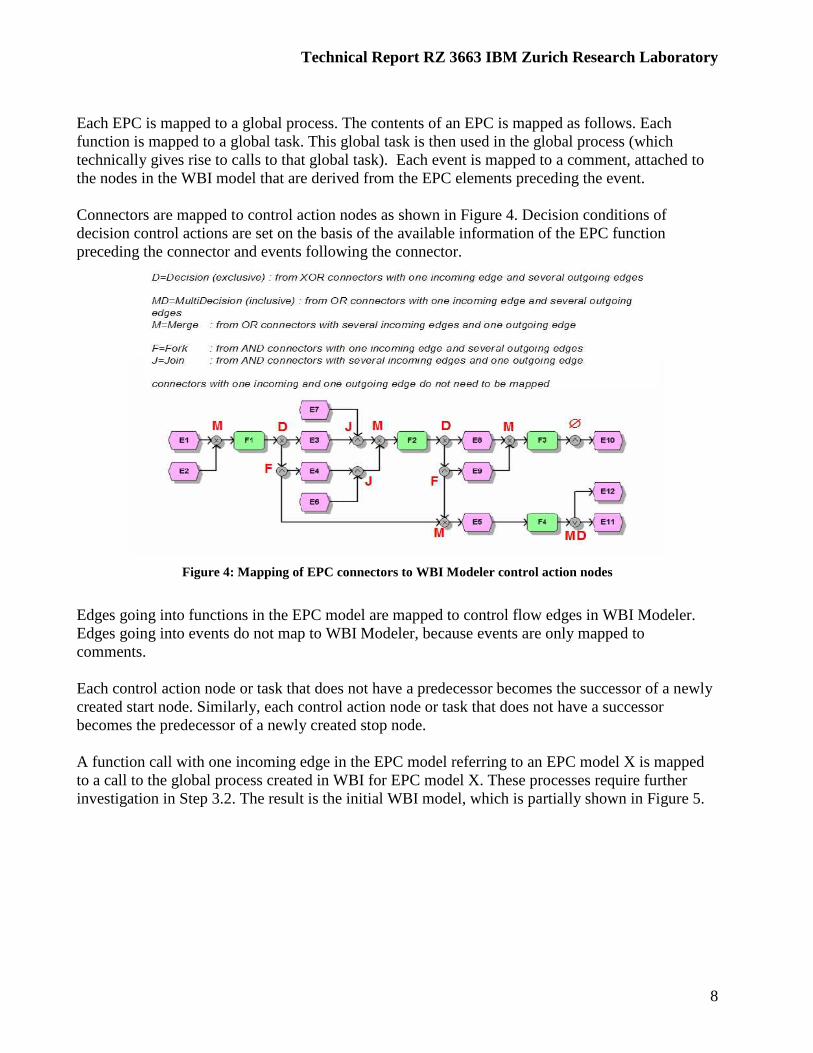
Each EPC is mapped to a global process. The contents of an EPC is mapped as follows. Each function is mapped to a global task. This global task is then used in the global process (which technically gives rise to calls to that global task). Each event is mapped to a comment, attached to the nodes in the WBI model that are derived from the EPC elements preceding the event. Connectors are mapped to control action nodes as shown in Figure 4. Decision conditions of decision control actions are set on the basis of the available information of the EPC function preceding the connector and events following the connector.
Figure 4: Mapping of EPC connectors to WBI Modeler control action nodes
Edges going into functions in the EPC model are mapped to control flow edges in WBI Modeler. Edges going into events do not map to WBI Modeler, because events are only mapped to comments. Each control action node or task that does not have a predecessor becomes the successor of a newly created start node. Similarly, each control action node or task that does not have a successor becomes the predecessor of a newly created stop node. A function call with one incoming edge in the EPC model referring to an EPC model X is mapped to a call to the global process created in WBI for EPC model X. These processes require further investigation in Step 3.2. The result is the initial WBI model, which is partially shown in Figure 5.
Technical Report RZ 3663 IBM Zurich Research Laboratory
9
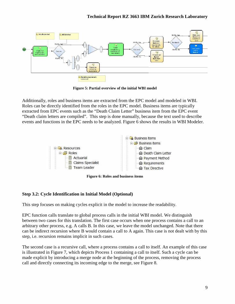
Figure 5: Partial overview of the initial WBI model
Additionally, roles and business items are extracted from the EPC model and modeled in WBI. Roles can be directly identified from the roles in the EPC model. Business items are typically extracted from EPC events such as the “Death Claim Letter” business item from the EPC event “Death claim letters are compiled”. This step is done manually, because the text used to describe events and functions in the EPC needs to be analyzed. Figure 6 shows the results in WBI Modeler.
Figure 6: Roles and business items
Step 3.2: Cycle Identification in Initial Model (Optional) This step focuses on making cycles explicit in the model to increase the readability. EPC function calls translate to global process calls in the initial WBI model. We distinguish between two cases for this translation. The first case occurs when one process contains a call to an arbitrary other process, e.g. A calls B. In this case, we leave the model unchanged. Note that there can be indirect recursion where B would contain a call to A again. This case is not dealt with by this step, i.e. recursion remains implicit in such cases. The second case is a recursive call, where a process contains a call to itself. An example of this case is illustrated in Figure 7, which depicts Process 1 containing a call to itself. Such a cycle can be made explicit by introducing a merge node at the beginning of the process, removing the process call and directly connecting its incoming edge to the merge, see Figure 8.

Technical Report RZ 3663 IBM Zurich Research Laboratory
10
Figure 7: Model with process calls resulting from EPC function calls
Figure 8: Resolved recursive process call
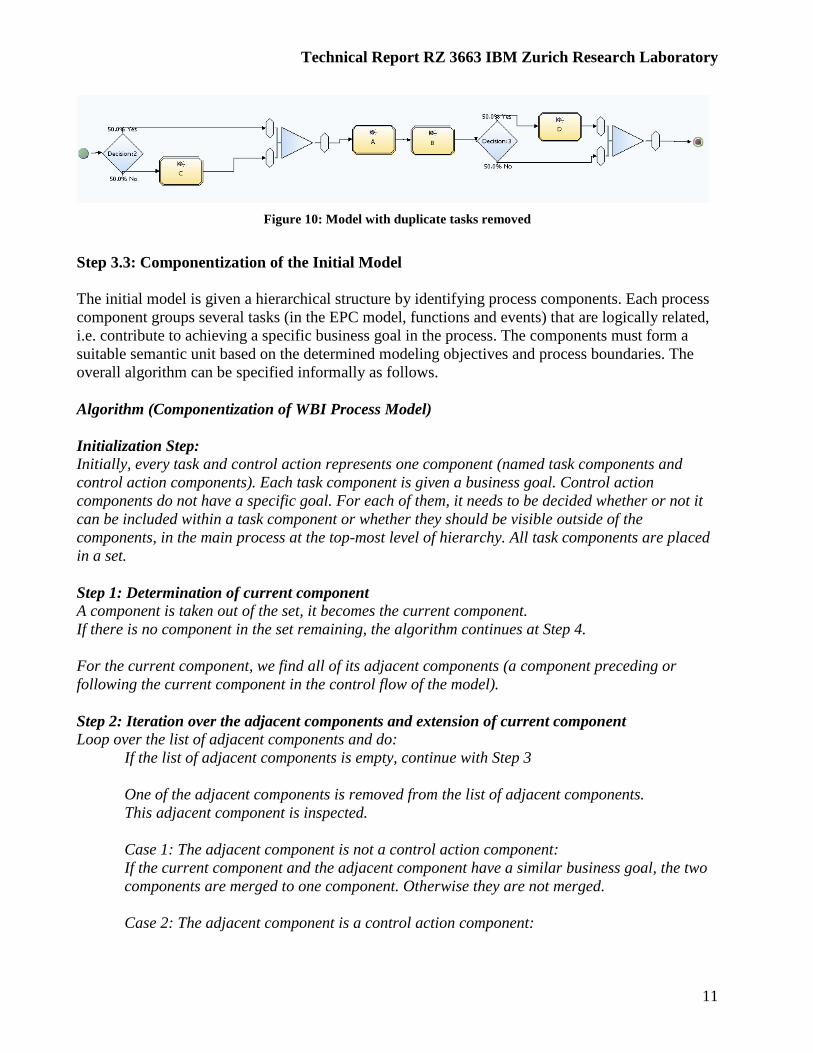
Further attention is paid to groups of tasks/processes that reoccur in different areas of the WBI model. In the WBI model, this leads to the use of calls to the same task/process in several areas of the model (see Figure 9 where duplicates of tasks A and B are denoted with A:2 and B:2). The duplicate tasks/processes can be removed. In order to achieve the same overall workflow, additional decisions and merges must be introduced and the control flow must be adapted. Conditions in the decisions must be set such that only execution sequences possible for the model before adaptation are possible afterwards. Figure 10 shows an example, where such control flow adaptation has been performed on the process shown in Figure 9. First, depending on the outcome of Decision:2, task C is optionally executed. This is followed by the execution of tasks A and B. Then, depending on the outcome of Decision:3, D is optionally executed. In some cases, this control flow adaptation may lead to cycles in the model. .
Figure 9: Duplicate tasks in the same model
Technical Report RZ 3663 IBM Zurich Research Laboratory
11
Figure 10: Model with duplicate tasks removed
Step 3.3: Componentization of the Initial Model The initial model is given a hierarchical structure by identifying process components. Each process component groups several tasks (in the EPC model, functions and events) that are logically related, i.e. contribute to achieving a specific business goal in the process. The components must form a suitable semantic unit based on the determined modeling objectives and process boundaries. The overall algorithm can be specified informally as follows. Algorithm (Componentization of WBI Process Model) Initialization Step: Initially, every task and control action represents one component (named task components and control action components). Each task component is given a business goal. Control action components do not have a specific goal. For each of them, it needs to be decided whether or not it can be included within a task component or whether they should be visible outside of the components, in the main process at the top-most level of hierarchy. All task components are placed in a set. Step 1: Determination of current component A component is taken out of the set, it becomes the current component. If there is no component in the set remaining, the algorithm continues at Step 4. For the current component, we find all of its adjacent components (a component preceding or following the current component in the control flow of the model). Step 2: Iteration over the adjacent components and extension of current component Loop over the list of adjacent components and do:
If the list of adjacent components is empty, continue with Step 3
One of the adjacent components is removed from the list of adjacent components. This adjacent component is inspected. Case 1: The adjacent component is not a control action component: If the current component and the adjacent component have a similar business goal, the two components are merged to one component. Otherwise they are not merged. Case 2: The adjacent component is a control action component:

Technical Report RZ 3663 IBM Zurich Research Laboratory
12
If the control action can be included into the component, then the current component is merged with the adjacent component. Otherwise they are not merged.
End of Loop Step 3: Adaptation of set If there has been a merge in Step 2, the new component is placed in the set and all new subcomponents of the new component are removed from the set. The algorithm continues at Step 1. Step 4: Conversion of components to processes All components are converted to global processes. All tasks/control actions within the components are moved into the processes. For a component with a single control action, no process is created. Step 5: Creation of start and end nodes in the processes Each component is inspected and start and stop nodes are created. These start and end nodes are connected to the tasks/control action nodes without predecessors/successors within the process to preserve the control flow before componentization. Figure 11 shows an example of the componentization before executing Step 4 of the algorithm. Only the task components are shown in blue color, components with control actions only (e.g. decisions) are not visualized. By repeating the algorithm, several hierarchy layers of components can be created. How many layers are useful, depends on the size of the model and the modeling objective.
Figure 11: Intermediate result of the componentization
Make Accept/Reject Decision
Check Completeness of Requirements
Check Submittal of Requirements
Obtain More Info
Obtain More Info
Reject Claim Settle Claim
Make Payment
Reject Payment
Check Decision

Technical Report RZ 3663 IBM Zurich Research Laboratory
13
Step 3.4: Manual control flow and component adjustment The control flow resulting from the previous step is revisited with the customer for confirmation and adjustment. Since the EPC approach does not differentiate between decision/fork and join/merge constructs, it can happen that semantic errors in the EPC now become apparent in the WBI AS-IS analysis model. In particular, the EPC AND constructs lead to semantic problems if a fork does not have a corresponding join in the WBI model. The EPC XOR/OR constructs (which are mapped to a decision) typically do not induce semantic problems. In order to find semantic problems due to fork constructs, the WBI model is examined for forks without corresponding joins. Figure 12 shows one of these problems for the example.
Figure 12: Problematic control flow in component Check Completeness of Requirements
In case of such semantic problems, the customer is asked whether or not it is necessary to have a fork and thus create several threads of control flow without joining these flows within the current component. Further, it is inquired whether it is necessary to have two starting nodes for this component. In our example, we assume that it is agreed to adjust the control flow inside the component “Check Completeness of Requirements” as shown in Figure 13, i.e. a join is added and the merge is deleted.
Figure 13: Control flow adjustment in components

Technical Report RZ 3663 IBM Zurich Research Laboratory
14
The top-most process resulting from the componentization step and control flow adjustment is shown in Figure 14.
Figure 14: Result of componentization after control flow adjustment
Step 3.5: Awareness of Business Methodology
While building the AS-IS analysis model, the modeling methodology has been further refined. In the last step, the stakeholders are made more conscious of the methodology and modeling process:
o Business terminology: naming conventions for business processes, tasks and subprocesses.
o Levels of hierarchical abstraction: how many layers of subprocesses are used, what details are ignored, what is the degree of reuse of subprocesses.
With that, the phase of building the AS-IS Analysis Model is completed.
Phase 4: Construct Mapping Between AS-IS and Reference Models Effort put into the AS-IS and TO-BE modeling phases has been shown to significantly speed-up and facilitate the subsequent design phase. The previous section developed detailed steps for the AS-IS analysis model creation phase by leveraging modeling assets that exist at the customer’s site. Reusing the legacy model ensures that existing requirements and constraints are brought early into the process model. The objective of the next phase is to facilitate the creation of the TO-BE analysis model by determining the differences of the current business process as captured in the AS-IS analysis model and best-practice reference models. Input:
o AS-IS analysis model in WBI, reference models in WBI

Technical Report RZ 3663 IBM Zurich Research Laboratory
15
Output:
o Detailed mappings between the AS-IS analysis model and relevant reference models including subprocesses, tasks, and control flow.
The reference model helps to focus on future business needs and architecture alternatives. It serves the following purposes:
o it facilitates the SWOT analysis (strengths, weaknesses, opportunities, and threats) and the identification of problem areas
o it helps to identify the necessary changes and stimulates ideas for new process designs (because of the AS-IS vs. reference model difference analysis)
The reference model also leads to TO-BE process models of higher quality. The reference model captures best practices for industry-specific business process design. Tasks/subprocesses in process models relate to services provided in associated implementation and component models, i.e. the reference model serves not only as a guideline at the analysis level, but it already reaches into the architectural and implementation level and combines business and IT-oriented modeling elements. Identifying the “right services” (the main problem in SOAD) becomes thus much easier and the gap between enterprise and solution architecture is reduced as the reference model has already bridged this gap significantly.
Figure 15: Overview of the IAA Reference Models
The IAA reference model package comprises many different models of various model types, as shown in Figure 15. Reference models differ significantly from OO and SOA design patterns:
o They are much larger, i.e. diagrams range across many pages and have a hierarchical structure, while design patterns usually cover a single page of a diagram augmented with textual explanation.
o They use many different model types: flow diagrams, organization diagrams, tabular descriptions, text, expressions and rules, while design patterns are represented in one or very few representations, e.g. class diagrams and text.

Technical Report RZ 3663 IBM Zurich Research Laboratory
16
For the following discussion, we focus on reference models in the form of business process models. Step 4.1: Compare AS-IS and Reference Modeling Objectives and Process Boundaries The first step of this phase compares process boundaries and modeling objectives for the AS-IS and reference models. Modeling objectives have been captured in the first step of the first phase for the AS-IS model. The modeling objectives for the reference model are available from the reference documentation. The AS-IS modeling objectives and the reference modeling objectives must be compatible with each other. If the reference modeling objectives are very different from the AS-IS modeling objectives, the reference models cannot serve as appropriate guidelines for the creation of the TO-BE analysis model and a different reference model must be chosen. The result of this step is the selection of reference models that have compliant modeling objectives. Based on the AS-IS process boundaries, the relevant process models are selected from the reference models. Usually, a single most relevant reference process model with similar objectives will be the outcome of this step. Step 4.2: Map AS-IS Tasks and Reference Tasks Goals of mapping: The goal of the mapping between AS-IS tasks and reference tasks is to find out semantic correspondences between the two processes. As the tasks represent the actual behavior of the processes, they provide a basis of such a detailed comparison. Note that although tasks might have different names in the AS-IS and reference processes, they can still include the same behavior. Typically, the behavior of a task is partially captured by the name and partially by its informal textual description. The mapping between the tasks of the AS-IS process and those in the reference process is determined based on this information and additionally by detailed discussions of each task by the business analysts. We distinguish between the following task correspondence types:
1. 1 to 1: One AS-IS task can be directly mapped to one reference task. In the example, “Make Own Decision on Outcome of Claim” maps to “Decide on Claim” (see Figure 16).
2. 1 to 0: The AS-IS model contains a task, for which no mapping task in the reference model can be found. In the example, “Check Completeness Correctness of Requirements” cannot be found in the reference model (see Figure 16).
3. 0 to 1: The reference model contains an additional task that has no correspondence in the AS-IS model. In the example, many tasks in the reference model have no correspondence in the AS-IS model, e. g. some tasks in the “Validate Claim” subprocess (see Figure 16).
4. 1 to many: The AS-IS model contains a task, that has several corresponding tasks in the reference model. In the example, “Determine Decision or Requirements for Referral”is mapped to several tasks in “Validate Claim” (see Figure 16).

Technical Report RZ 3663 IBM Zurich Research Laboratory
17
Note that the previous categorization is based on the idea to look from the AS-IS model to the reference model. Taking the reference model as a starting point would lead to a different categorization, including the many-to-1 relationship. We distinguish between the following content relationship types:
1. Included: The content of the AS-IS task is included in the content of the reference task. 2. Comprises: The content of the AS-IS task comprises more content than the content of the
reference task. 3. Equal: The content of the AS-IS task and the reference task are equal. 4. Overlapping: The content of the AS-IS task and the reference task are overlapping but they
are neither included nor comprised. The following algorithm describes a systematic approach how a task mapping can be constructed: Algorithm (Task mapping): Initialization step: All tasks of the AS-IS model are placed into a set of AS-IS tasks. Mapping step: Loop over all tasks in the AS-IS task set If no task remains the set, terminate loop
Remove a current AS-IS task from the set Identify task correspondence type to tasks in the Reference set If a task correspondence type of 1 to 1 has been identified do Identify content relationship type of AS-IS task to the reference task If a task correspondence type of 1 to many has been identified do Identify content relationship type of AS-IS task to related reference tasks End of Loop
1 to many correspondence
1 to1 correspondence
Figure 16: Task correspondences for the example

Technical Report RZ 3663 IBM Zurich Research Laboratory
18
Figure 17: Task correspondences for the example
All correspondences are documented in a detailed task mappings table, which serves as a work list for the subsequent phase of the BPM (see Figure 18). The mappings table in Figure 18 only shows a subset of the task mappings from the example. AS-IS Element Task
Correspondence Type
Content Relation-ship Type
Reference Model Elements affected
Check Completeness, Correctness of Requirements
1 to 0
Determine Remaining Requirements
1 to 0
Make Own Decision on Outcome of Claim
1 to 1 Equal Decide on Claim
Drop Case 1 to 1 Included Close Claim Determine Decision or Requirements for Referral
1 to many Analyse Claims History for Claim, Evaluate Claim Value, Decide on Loss Coverage
Figure 18: Task mappings table
At the end of this mapping process, a correspondence for each task of the AS-IS model was either found or not found in the reference model. Each of the correspondence types leads to specific actions in the subsequent phase of the BPM.

Technical Report RZ 3663 IBM Zurich Research Laboratory
19
Step 4.3: Calculate Subprocess Relationships On the basis of the task correspondences, a relationship of the (sub)processes can be established between the AS-IS model and the reference model. This relationship captures the similarities and differences on the subprocess level and is later used for a systematic adjustment of the reference model to the AS-IS model (tailoring). We distinguish between the same kinds of correspondences as for tasks (1 to 1, 1 to many, 1 to 0, 0 to 1). Algorithm (Subprocess relationships): Precondition: Task correspondence types have been established. Step 1 (Calculate depth of subprocesses): Calculate the depth of each subprocess in the AS-IS model, we assume that the top-level process gets value 0. We also calculate the maximal depth of all subprocesses. Step 2 (Calculate 1 to 1, 1 to many, 1 to 0): For l = maxdepthlevel downto 0 do For each subprocess s at level l in the AS-IS model do RelSubs = {}
For each task t within s do If task t is related (1 to 1, 1 to many) to a task r in the reference model Find all subprocesses subs that r is contained in RelSubs = RelSubs Union subs Establish relationships:
Sort RelSubs according to their depths Let SubsMaxDepth be those subs in RelSubs with the highest depth number If s is related to only one subprocess (SubsMaxDepth has one element) , then a 1 to 1 relationship is introduced to the subprocess in SubsMaxDepth.
If s is related to several subprocesses (SubsMaxDepth has more than one element), then a 1 to many relationship is introduced between s and the subprocesses in SubsMaxDepth If s is not related to any subprocess, then it is marked as not mapped (1 to 0).
Step 3 (Calculate 0 to 1): For l = maxdepthlevel downto 0 do For each subprocess s at level l in the reference model do If s is not related to any subprocess in the AS-IS model, mark it accordingly. The result of the previous algorithm is a detailed view of how a subprocess in the AS-IS model is related to one or more subprocesses in the reference model and also which subprocesses in the reference model have subprocesses with corresponding functionality in the AS-IS model. This provides a basis for adjusting process compositions and adding tasks. Figure 19 shows subprocess correspondences for the example.

Technical Report RZ 3663 IBM Zurich Research Laboratory
20
1 to many task correspondence
1 to1 task correspondence
1 to1 subprocess correspondence
Figure 19: Subprocess correspondence
The subprocess relationships also indicate whether the structure of the AS-IS model and the reference model are already aligned: In the case that a subprocess in the AS-IS model is related to a subprocess in the reference model and they have different depths, then there is a structural mismatch. As an example consider Figure 19 where the “Make Accept Reject Decision” subprocess (depth = 1) is related to the “Administer Claim” (depth 0). This means that here the structure is not aligned yet. On the other hand, the “Reject Claim” is related to “Validate Claim” and here we have an aligned structure. Phase 5: Derive TO-BE Analysis Model The objective of this phase is to create the TO-BE analysis model of the future business process that is expected to meet the modeling objectives. The mappings produced as the result of the previous phase serve as the starting point for deriving the TO-BE process model. The task mapping table sets the direction for how the reference model will be adjusted to arrive at the TO-BE analysis model. Input:
o Mappings between the AS-IS model and the reference model o Summary statement
Output:
o TO-BE analysis model

Technical Report RZ 3663 IBM Zurich Research Laboratory
21
Step 5.1: Adapt Content of Tasks The reference process model is taken as the starting point and serves as the initialTO-BE process model that is gradually modified. In this step, the content of all tasks is reviewed and adapted if necessary. The overall adaptation can be organized along the correspondence types: For a 1 to 1 correspondence, for the case of equal content type, nothing has to be done. For an included or comprised content type, the functionality of the reference task is either extended or reduced, respectively. In case of an overlapping content type, the functionality which is missing in the reference task can be added in the TO-BE model. For a 1 to many correspondence, for the case of equal content type, nothing has to be done. For an included, comprised or overlapping content type, the functionality of the reference task is either extended or reduced in the TO-BE model. Step 5.2: Alignment of AS-IS and Reference Model Subprocesses and Tasks After adaptation of the contents of the tasks, differences between the reference model and the AS-IS model remain concerning the tasks used in the models, the organization of tasks into subprocesses, and concerning the control flow. In this step, we show how the first two differences can be systematically treated. In general, we can distinguish between different kinds of changes that are made in this step: If tasks are added to the TO-BE model, then this is a certain form of customization of the initial TO-BE model. If tasks are removed, then the initial TO-BE model is made more concrete for the customer. For example, if a reference model takes into account different lines of business, but the customer only deals with one of them, several tasks in the TO-BE model may be removed. The fewer changes are made to the reference model, the closer will the resulting TO-BE model be to the best practice. The more changes are made, the closer will the resulting TO-BE model be to the existing AS-IS model. The ideal amount of changes is different for each customer situation and is found by strictly obeying modeling objectives and considering IT legacy constraints. It is important to note that the reference model is adjusted to obtain the TO-BE analysis model and not the AS-IS model, in order to avoid the problem of a pure top-down modeling approach. The subprocess correspondences provide the basis for a detailed subprocess adjustment. The subprocess correspondences 1 to 1 and 1 to many can lead to different situations when looking inside the related subprocesses (see Figure 20). In each situation, the difference between the AS-IS model and the reference model must be taken into consideration and resolved if there is a customer need for aligning the TO-BE model (initially this is the reference model) to the AS-IS model. The possible actions for aligning the TO-BE model are described informally in Figure 20. For each subprocess, the corresponding situation shown in Figure 20 is identified. Then, the possible action (PA) is discussed with the customer and the reference process is adapted accordingly. All actions taken should be documented in a table for later justification and traceability.

Technical Report RZ 3663 IBM Zurich Research Laboratory
22
Subprocess 1 Task 1
Task 2
Subprocess 2 Task 1’Task 2’
a)
b1)
Conditions and Possible Actions:
Subprocess 1Task 1
Task 2
Subprocess 2 Task 1’
There exist tasks in Subprocess 1 that are not related to tasks in Subprocess 2and these tasks are not related at all to other tasks.
PA: - Possibly add task 2
b2)
Subprocess 1Task 1
Subprocess 2Task 1’Task 2’
There exist tasks in Subprocess 2 that are not related to tasks in Subprocess 1and these tasks are not related at all to other tasks
PA: - Possibly remove task 2’
AS-IS Current TO-BE (initally reference)
c1)Subprocess 1
Task 1Task 2
Subprocess 2Task 1’Task 3’
Tasks in Subprocess 1 are related to tasks in different subprocesses.
PA: - Merge Subprocess 2 and Subprocess 3 - Remove task 3’ and task 4’
Subprocess 3Task 2’Task 4’
c2)
Subprocess 1Task 1Task 3
Subprocess 2Task 2Task 4
Tasks in Subprocess 3 are related to tasks in different subprocesses.
PA: - Split Subprocess 3- Add task 3 and task 4
Subprocess 3Task 1’Task 2’
d1)
Subprocess 1 (level i)Task 1Task 2
Process 1Task 1’Task 3’Subprocess 2 (level i)
Task 2’Task 4’
Tasks in Subprocess 1 are related to tasks on differ ent subprocess levels.
PA:-Consider moving Task 1’ inside Subprocess 2
d2) Subprocess 1Task 1’Task 2’
Process 1Task 1Task 3Subprocess 2
Task 2Task 4
Tasks in Subprocess 1 are related to tasks on different subprocess levels.
PA:- Consider moving Task 1’ out of Subprocess 1
All tasks in Subprocess 1 are related 1 to 1 to tasks in Subprocess 2
PA: None.
Subprocess 1 (level i)Task 1
Process 1Task 1’ (level i)
Tasks in Subprocess 1 are related to tasks on different levels and Subprocess 1 is related to the top level process.
PA: - Possibly consider moving all tasks of Subprocess 1 into a newly created Subprocess in the TO-BE model
d3)
Subprocess 1Task 1Task2
Subprocess 2Task 1’Task 3’
b3)There exist tasks in Subprocess 1 that are not related to tasks in Subprocess 2 and there exist tasks in Subprocess 2 that are not related to tasks in Subprocess1 and non-related tasks are not related at all to other tasks
PA: - Possibly add task 2 and remove task 3’
Figure 20: Subprocess configurations
The model granularity is now adjusted according to the modeling objective, process boundaries and IT constraints given at the customer side. Step 5.3: Adjust Control Flow The value of the different orderings, optional and mandatory tasks/subprocesses, different dependencies and decision points in the reference model is assessed in terms of the modeling objective. Adjustments to the reference model are made when the value is non-obvious or IT legacy constraints require them. Adjustments from the previous step with respect to the subprocesses may also impact the control flow in the reference model and may lead to additional adjustments that take place now. It is important to note that the control flow should only be changed when it is clear that the customer has special needs that justify the control flow to be different to that in the reference model

Technical Report RZ 3663 IBM Zurich Research Laboratory
23
as the reference model represents a best practice from which deviations should be kept at a minimum. The overall adjustment of control flow can be organized on a subprocess basis where the control flow of related subprocesses is compared and adapted accordingly. The resulting control flow is validated by several interactive walkthroughs with the customer and/or by using validation/simulation capabilities provided by the modeling tool. Figure 21 shows the result for our example process.
Figure 21: Resulting TO-BE analysis model
Step 5.4: Perform AS-IS/TO-BE comparison Once the TO-BE model has been completed for the top-level subprocesses, an AS-IS/TO-BE comparison must be performed to evaluate if the current process design considers all constraints and meets the modeling objectives. Analysis and simulation capabilities for the comparison from a BPM tool such as WBI Modeler are exploited in this step. The step is known from existing BPM.
Phase 6: Derive TO-BE Design Model A design model describes how a business process is realized using hardware, software, and people. It is obtained from the analysis model by adding further details to the model and making structural changes to it. The changes reflect existing application systems, meet restrictions of the target IT programming model, and lead to an IT-based flow of data and control. A design model is ready to be mapped to the programming model (e.g. WSDL/BPEL) by automatic model transformations that provide code generation for the target programming model. The objective of this phase is to transform the TO-BE analysis model of the business process into the TO-BE design model. Input:
o TO-BE analysis model o target programming model and restrictions
Output:
o TO-BE design model

Technical Report RZ 3663 IBM Zurich Research Laboratory
24
Step 6.1: Define Design Object Model The TO-BE analysis model of the business process contains definitions of the relevant business items that represent the information required by the various subprocesses. This information was extracted in Phase 3 by analyzing the objects/principal artifacts that we mentioned in the text of functions and events in the EPC. Figure 22 summarizes the information from the example. The business items represent this information at the business (analysis) level without taking into account IT requirements.
Figure 22: Business items extracted from example EPC model
A first design decision is to determine the data container that will carry this information across the process implementation. As our target programming model is a SOA based on Web services described in the WSDL standard using explicit service choreographies described in the BPEL standard, the information is transported in a data container represented as an XML message. The type of this XML message is defined using an XML schema (XSD). The schema can be imported from the SOA existing at the customer’s site or it can be a newly defined schema by reusing and/or adopting the reference business object model. Usually, such a model is given as a UML class diagram as shown in Figure 23 for the IAA Business Object Reference Model for the “Claim Folder” object.
Figure 23: IAA Business Object Reference model for Claim folder

Technical Report RZ 3663 IBM Zurich Research Laboratory
25
The reference model defines standard terminology for business objects, which may differ from the terms adopted in the customer’s business. Adoption of the reference terminology by the customer or adjustment of the reference object model terminology and the model itself to the requirements of the customer needs may be necessary. If the customer has no well-established terminology and object models in place, or if an integration of systems based on different terminologies or models needs to take place (e.g. after a merger/acquisition), the adoption of the reference object model by the customer is recommended. Once the terminology of objects in the reference model has been finalized, the associations and other relations between objects are considered. The meaning of the relations and associations needs to be explained to the customer, so that the customer can verify that the data model correctly captures their understanding of their own data in the business. The relations are adjusted in places where special customer needs require changes to the reference data model. The finalized object model is imported into the business process modeling tool (WBI Modeler) where it becomes available as a design-level business item. Step 6.2: Assign Data Container The design-level business item represents the data container that will carry the required information across the implemented business process. The business item is assigned along the control flow of the TO-BE analysis model using a plugin into WBI Modeler that provides the model transformation. Figure 24 summarizes this step.
ReferenceObjectModel
CustomizedReference
ObjectModel
(optional)
Design-level Business Item
LegacyObjectModel
TO-BEDesign Model
Model Import
Data Container Assignment Plugin
in WBI Modeler
Model Transformation
Figure 24: Data container assignment
Figure 26 shows a subpart of the design model for our example once the data container has been assigned.

Technical Report RZ 3663 IBM Zurich Research Laboratory
26
Figure 25: Part of the TO-BE Design Model after Claim Folder assignment
Step 6.3: Refine Data-Based Decision Conditions Once the data container has been assigned to the control flow in the design model, the decisions that occur in the model can be refined with conditions expressed in terms of specific data values. For example, a condition that was captured informally at the analysis level as “All Covered” in Figure 25 is now turned into the formal expression shown in Figure 26 from which executable code can be generated.
Figure 26: Refinement of decision conditions based on assigned data container
Step 6.4: Meet IT programming model constraints Additional model transformations are applied iteratively to further shape and refine the TO-BE design model. The method comprises one fundamental transformation that is required to meet the

Technical Report RZ 3663 IBM Zurich Research Laboratory
27
current BPEL standard. While business process models usually contain unstructured cycles, these unstructured cycles need to be replaced by structured loop nodes in BPEL [7].2 A model transformation plugin is now executed to perform this replacement in the TO-BE design model in WBI Modeler. The result is a business process model that meets the restrictions of the BPEL export in the Modeler, i.e. the resulting design model is now ready for code export to automatically produce the programming model. With these last transformation steps, the BPM presented in this report is complete. The transformations from the analysis model to the design model are repeatable to easily accommodate design changes. They also form the basis to establish synchronization links between the analysis and design model and the design model and the programming model. The structural similarity between the design model and the programming model (BPEL) makes it easier to synchronize and maintain both models and propagate future design changes to the programming model.
References [1] Zimmermann O., Krogdahl P., Gee C (2004). Elements of Service-Oriented Analysis and Design. IBM developerWorks. [2] Deborin E. et al (2002). Continuous Business Process Management with HOLOSOFX BPM Suite and IBM MQSeries Workflow. IBM Redbooks. (http://www.redbooks.ibm.com/redbooks/pdfs/sg246590.pdf ). [3] Endrei M. et al (2004). Patterns: Service-Oriented Architecture and Web Services. IBM Redbooks. (http://www.redbooks.ibm.com/redbooks/pdfs/sg246303.pdf ) [4] www.workflowpatterns.com [5] Gamma E., Helm R., Johnson R., Vlissides J. (1995). Design Patterns. Addison-Wesley. [6] Scheer A-W. (1994). Business Process Engineering. Springer. [7] J. Koehler et al (2005). Declarative Techniques for Model-Driven Business Process Integration. IBM Systems Journal 44(1), 2005, pages 47-65.
2 A plugin for WebSphere Business Modeler is available that automates this and other tasks. Note that the patents have been submitted that protect the technology.