Methodologies for Model-Driven Development and Deployment...
20
Methodologies for Model-Driven Development and Deployment: an Overview L´ aszlo G¨ onczy, ´ Abel Heged¨ us, and D´ aniel Varr´ o Budapest University of Technology and Economics, Hungary {gonczy,hegedusa,varro}@mit.bme.hu 1 Introduction This chapter introduces a model-driven Sensoria approach for service engineer- ing. The project delivered a comprehensive approach for service modeling, anal- ysis and deployment with novel modeling languages, qualitative and quantitative techniques for service analysis, automated model driven deplyoment mechanisms and legacy transformations. Model transformation served as a key technology for model-driven service engineering. The first part of the chapter first discusses the overall methodology and then briefly overviews some key contributions of the project (Sec. 2). Obviously, these individual contributions are presented from the viewpoint of model-driven development. Most of these are discussed in detail in other chapters of this book or in publications related to the project. The second part (Sec. 3) presents a selected ”end-to-end” example for using model-driven techniques for analysing services. Here high-level, standard models of business processes and their correctness requirements are translated to a for- mal model (namely, transition systems and temporal logic formulae) in order to enable exhaustive verification by a model checker, which is a common scenario in the Sensoria project. Furthermore, this forward model transformation is also complemented with the back-annotation of analysis results to the original service models. The tech- nique we present enables the easy visualization/simulation of model checker results right on the original business processes, therefore enabling the service developer to correct design flaws. The tool support integrated into the Sensoria Development Environment is briefly discussed in Sec. 3.5. Finally, Section 4 discusses related work and Section 5 concludes the paper. 2 Overview on Model-Driven Methodologies 2.1 The Sensoria Service Engineering Approach This crosscutting chapter presents the engineering vision of the Sensoria project, which facilitates a model-driven development approach. After a brief conceptual introduction, the chapter presents a high-level overview in order to demonstrate the feasibility of the approach by summarizing selected achievements in the project from a practical, engineering and tool-oriented viewpoint.
Transcript of Methodologies for Model-Driven Development and Deployment...

Methodologies for Model-Driven Developmentand Deployment: an Overview
Laszlo Gonczy, Abel Hegedus, and Daniel Varro
Budapest University of Technology and Economics, Hungary{gonczy,hegedusa,varro}@mit.bme.hu
1 Introduction
This chapter introduces a model-driven Sensoria approach for service engineer-ing. The project delivered a comprehensive approach for service modeling, anal-ysis and deployment with novel modeling languages, qualitative and quantitativetechniques for service analysis, automated model driven deplyoment mechanismsand legacy transformations. Model transformation served as a key technology formodel-driven service engineering. The first part of the chapter first discusses theoverall methodology and then briefly overviews some key contributions of theproject (Sec. 2). Obviously, these individual contributions are presented from theviewpoint of model-driven development. Most of these are discussed in detail inother chapters of this book or in publications related to the project.
The second part (Sec. 3) presents a selected ”end-to-end” example for usingmodel-driven techniques for analysing services. Here high-level, standard modelsof business processes and their correctness requirements are translated to a for-mal model (namely, transition systems and temporal logic formulae) in order toenable exhaustive verification by a model checker, which is a common scenarioin the Sensoria project.
Furthermore, this forward model transformation is also complemented withthe back-annotation of analysis results to the original service models. The tech-nique we present enables the easy visualization/simulation of model checkerresults right on the original business processes, therefore enabling the servicedeveloper to correct design flaws.
The tool support integrated into the Sensoria Development Environmentis briefly discussed in Sec. 3.5. Finally, Section 4 discusses related work andSection 5 concludes the paper.
2 Overview on Model-Driven Methodologies
2.1 The Sensoria Service Engineering Approach
This crosscutting chapter presents the engineering vision of the Sensoria project,which facilitates a model-driven development approach. After a brief conceptualintroduction, the chapter presents a high-level overview in order to demonstratethe feasibility of the approach by summarizing selected achievements in theproject from a practical, engineering and tool-oriented viewpoint.

2
Actors in a service-oriented project A primary goal of the Sensoriaproject is to provide support for different stakeholders and actors during theentire project lifecycle for developing service-oriented overlay systems of a justi-fiable quality. These participants inevitably include the following ones:
– Domain experts are responsible for synthesizing requirements from business-related knowledge such as organization-specific roles, typical business sce-narios or workflows, or business-critical data. While domain experts are ob-viously experts in their own application domain, they typically lack generalsoftware (and service) engineering skills, thus high-level, easy-to-understandlanguages are essential for them to record their business knowledge.
– Service modelers are in charge of the technical design of service-orientedsystems which has to meet the business-related requirements. Service mod-elers are typically engineers with skills in modern service-oriented modelinglanguages and design technologies. However, they are typically less knowl-edgeable in how to provide guarantees for the proven quality of service.
– Service certifiers are frequently a project-independent entity or authoritybeing responsible for assuring the approved quality of services. While today,this role is still restricted to dedicated application areas (such as mission orsafety-critical applications), it is expected that the role of dependability (i.e.justifiable quality of services) will drastically increase in traditional businessareas. Service certifiers are typically skilled in formal (mathematical)analysisand testing techniques in order to carry out precise analysis of the servicewhich is currently in the design phase.
– Service managers are in charge of the proper deployment and maintenance(e.g. upgrade) of business-critical services. They are experts in the underlyingservice infrastructures.
Sensoria proposes a model-driven approach for the entire development cycleof services based applications and infrastructures including the design, the formalanalysis, the deployment and re-engineering of services. The core ideas of theSensoria engineering approach are illustrated in Fig. 1.
The main contributions of Sensoria can be summarized from an engineeringperspective as follows:
– Precise capturing of domain-specific requirements– High-level front-end service modeling languages– Hidden formal analysis of services– Deep semantic analysis for certification– Automated deployment of services to various infrastructures– Customizable orchestrator for tool integration– Model transformations for bridging models and languages– Reengineering of legacy services– Standards-compliant languages and service infrastructure
The current paper provides a brief, high-level overview of selected contribu-tions within each category above.
Experience on using these methods on Sensoria case studies is collected inChapter 7-2.
3
Fig. 1. The Sensoriaengineering approach
2.2 Contributions of Sensoria
Precise capturing of domain-specific requirements This work is an en-hancement of the Requirement Engineering technique presented previously. Herethe emphasis was on Business Process Reengineering where functional and se-curity requirements must be guaranteed during the engineering process. Thusthe connections between business processes and requirement models were inves-tigated and the notion of goal equivalence was introduced. A framework wasdefined to support Goal Equivalent Secure Business Process Reengineering in[17].
High-level front-end service modeling languages. In order to support ser-vice modelers, Sensoria facilitates the use of high-level front-end service mod-eling languages. A primary means for that is the definition of a service-orientedUML Profile, thus off-the-shelf UML CASE tools can be used by service engi-neers to construct service models. UML4SOA is described in detail in Chapter1-1.
As an alternate solution, Sensoria proposes a new domain-specific model-ing language (called SRML) for a rich semantic definition of components andservices. A visual SRML editor, and an EMF-compliant SRML metamodel isdeveloped, the approach is reported in detail in Chapter 1-2.
Hidden formal analysis of services As a core contribution, Sensoria facili-tates a model-driven, hidden formal analysis of service-oriented overlay systems.Since service modelers typically lack mathematical skills to carry out an in-depthanalysis of the system in an early phase of design, we carry out automated modelanalysis by transforming high-level service models into precise mathematicalmodels in order to carry out quantitative and qualitative analysis. Results of the

4
mathematical analysis are aimed to be back-annotated to the high-level modelsservice engineers, thus hiding the technicalities of the underlying mathematicalanalysis.
A method was created for model-based qualitative analysis of services via callby contract. Here UML models are passed to a static checker by automated modeltransformations in order to analyze service behaviour against security policies[20].
Techniques for model-based quantitative performance analysis of services byextracting a performance model from high-level service models captured in UMLwere also investigated. The performance model is mapped onto a stochasticprocess of the PEPA framework whose analysis allows the service modeller toobtain quantitative measures such as throughput and utilisation (Chapter 5-2and Chapter 5-3).
We proposed the use of Modes to abstract a selected set of services, and useUML2 models to analyse self-managing and reconfigurable service architecturesfor consistency and constraints. In addition, coordination processes may be syn-thesised to manage the changes in architecture as environmental changes occur.The approach is illustrated through the use of the Sensoria Development En-rivonemnt with collaborating UML2, Darwin and Ponder2 model-transformationto deployment artefacts (see Chapter 4-4).
Recently, we developed novel model-based analysis methods for service or-chestration designed in UML4SOA. Here we check consistency and protocol con-formance of service compositions described as UML activity diagrams and pro-tocols defined by UML state machines. Details of this method are provided in[18].
Finally, we also help service developers to estimate the cost of reliability (interms of response time overhead) by introducing performability analysis tech-niques for reliable messaging middleware. UML4SOA models with specificationson non-functional parameters of service communication are transformed intoPEPA models according to messaging mode/characteristics and the cost of mid-dleware configuration alternatives can be evaluated by sensitivity analysis (see[11] for details).
Deep semantic analysis for certification. The service-oriented calculi de-veloped in WP2 are intended for deep semantic analysis carried out by servicecertifiers having in-depth mathematical knowledge. Previously we also demon-strated that a model-driven approach is also applicable here as well by bridgingUML models of service orchestrations and sound formal notations. More specif-ically, a transformation is presented which maps UML activity diagrams to thesaga calculus. This allows a sound formal analysis of the orchestration’s controlflow based on a simple and formally easily amenable representation.
A transformation has also been developed to map UML4OSA models toJolie orchestrations which permits the use of the analysis features provided bySOCK, the formal background of Jolie [13]. This transformation is part of theMDD4SOA toolkit.

5
Automated deployment of services to standards-compliant service in-frastructures Service managers responsible for deploying and maintaining service-oriented applications need to face the challenge that more and more emphasisis put on the reliability, availability, security, etc. of such services. In order tomeet such non-functional requirements, a service needs to be designed for re-liability by making design decisions on a high, architectural level. Details ofthe techniques are presented in [12], where a model-driven approach for the au-tomated deployment of services to standards-compliant service infrastructuresis described. Starting from a platform-independent service model enriched bynon-functional attributes for reliable messaging, low-level service configurationdescriptors are generated by appropriate model transformations for standards-compliant middleware supporting reliable and secure messaging. This year weextended existing model transformations to include the Apache Axis2 platformas target execution environment.
As a ”side effect” of these developments, a novel approach is being investi-gated to facilitate the development of customizable model transformations. Asillustrated by the above techniques, there are multiple model transformationsduring analysis and development of service oriented systems. In these transfor-mations, typically there are steps where a high level system model is parsed inorder to generate a subset of the model which is relevant for a particular anal-ysis method (performance, security, etc) while other steps aim at the creationof deployment artifacts for different platforms (e.g. Web service implementationon Apache/IBM, considering different configuration constraints). These steps allneed similar model transformations/translations which can be ”parametrized”by high level engineering models. This approach needs the development of modelsrather than transformations.
Customizable orchestrator for tool integration. Different application do-mains and organizations frequently need to customize the overall developmentprocess to the specific needs of the domain. However, when new tools are in-tended to be added to the workflow of the organization, this requires significantefforts in tool integration. In order to bridge the gap between the developmentprocess and the development tools (thus reducing the complexity of tool inte-gration), the Sensoria Development Environment (SDE) is provided, acting asa central orchestrator for individual tools and services. SDE uses Eclipse basedde facto standards, such as EMF-based interfaces for models and OSGI servicesfor design, analysis, model transformation and deployment steps.
Advances on the SDE and currently integrated tools are described in Chapter6-5.
Model transformations for bridging models and languages. The model-driven development, analysis and deployment of services with justifiable qualitynecessitates that the automated model transformations bridging different lan-guages and tools are precise themselves. Sensoria builds on modern Eclipse-based model transformation frameworks (such as VIATRA2 and the TIGER

6
EMF Transformer) supporting standards EMF-based interfaces with precisemathematical foundations provided by the paradigm of graph transformation.
Furthermore, we have also investigated innovative ways for accelerating theprocess of designing model transformations. Model transformation by exampleis a novel approach in model-driven software engineering to derive model trans-formation rules from an initial prototypical set of interrelated source and targetmodels, which describe critical cases of the model transformation problem in apurely declarative way.
Recently, we investigated techniques for incremental, live model transforma-tions. We adapted the well-known RETE algorithm from the field of rule-basedsystems to make pattern matching more efficient, therefore reducing executiontime of model transformations. We implemented the algorithm for the VIATRA2model transformation framework. Unlike batch transformations, live transfor-mations are triggered by model changes and they are executed incrementally tosynchronize models.
Furthermore, the Moment-GT model transformation engine has been devel-oped to facilitate verifiable model transformations using the Maude rewritinglogic engine as formal background. These techniques are presented in Chapter6-2).
Reengineering of legacy services In order to support the reengineering andredeployment of existing legacy applications to more modern service-orientedplatforms, the reengineering methodology is summarized from the global soft-ware engineering view of SensoriaEach instantiation of the methodology de-termines what programming language can be used as input and what concreteplatform will the services adhere to. Reengineering is also carried out by modeltransformations (Chapter 6-4).
Standards-compliant languages and service infrastructure In order towiden the practical usability of results, interfaces and platforms used withinthe Sensoria engineering approach are compliant with standards and/or indus-trial best practices. For instance, service models are captured in UML, BPELor using EMF-compliant graphical editors in Eclipse. Target deployment plat-forms include service infrastructures supporting various WS-* standards on sev-eral (IBM, Apache) platforms. Services are deployed by using standard servicedescriptors such as WSDL, and currently there is an ongoing development tosupport SCA.
3 From BPEL to SAL and Back: an End-to-End Exampleon Model-Driven Analysis
The development of a fully-fledged verification tool directed by model-drivenanalysis necessitates the application of numerous model-based techniques. In

7
this section these techniques are presented through a complex end-to-end ex-ample implementation providing design-time verification support for businessprocesses. First the verification approach is described, followed by a short pre-sentation of the challenges in model-driven analysis. Finally the usage of thedifferent techniques are described on the example implementation.
3.1 Practical Design-time Verification of Business Processes
Motivation Business processes are often used to coordinate the work of differentstakeholders in business-to-business collaborations as well as Enterprise Appli-cation Integration. Since these workflows set up the cooperation between actors,their quality is critical to the organization and any malfunction may have asignificant negative impact on financial aspects. To minimize the possibility offailures, designers and analysts need powerful tools to guarantee the correctnessof business workflows.
Approach The main steps of the method presented in [16] are illustrated in Fig. 2.In the current chapter, we restrict our investigations to using BPEL as an in-put language. However, the Sensoria toolset offers the higher-level UML4SOAmodels to capture business processes and derive actual BPEL descriptions byautomated model transformation. In the next step, the input BPEL businessprocess description is transformed into a formal model in the form of state tran-sition systems. In the second stage, this transition system is projected into thelanguage of the Symbolic Analysis Laboratory (SAL) [25]. The actual verificationis then carried out with symbolic or bounded model checking techniques [26].Requirements against the business process are captured as the expressions ofthe Linear Temporal Logic [5]. General (application-independent) requirementsand arbitrary business process-specific requirements may be verified with themodel checking technique. As a distinctive feature of this verification technique,it provides support for analysing error propagation between variables.
Fig. 2. BPEL Verification approach overview
In the method, model checking is used for verification purposes. The result ofmodel checking is a sequence of actions which violate the requirement (counter-example). The system satisfies the requirement if a counter-example cannot befound. The counter-example represents an execution of the BPEL process, butderiving and presenting this execution is non-trivial.
8
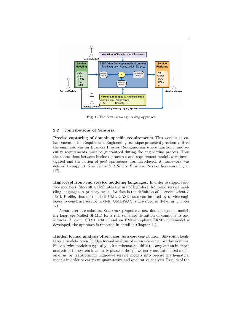
Running example The Sensoria project incorporates complex case studies fromdifferent domains which are used for demonstration purposes. We selected theFinance Case Study [2] as a running example for our paper. The case studyincludes a credit request process which we modeled in BPEL, a simplified versionof the process is shown on Fig. 3.
Fig. 3. Credit request BPEL process
The credit request process starts with a Login part where the client logs inthe system, if the login is successful, the main part (Scope) of the process starts,enabling anEvent handler executed if the process is canceled and a Faulthandler for catching errors. Next a cycle is started (Repeat until) which re-

9
peats as long as the request is not accepted and updates are made. The cycle corestarts with creating a new request, followed by entering the Balance andSecurity data and Calculating the rating. If the rating is AAA the ratingis accepted at once, otherwise BBB ratings are approved by a clerk, the rest areapproved by a supervisor. After the approval is returned (Wait for approval),the request is accepted if the rating was accepted (Rating accepted?). If therequest is rejected (Reject request), the client can update the request and tryagain. Finally the process finishes after logging out.
Verification example The implemented running example business process wasverified using general requirements. Fig. 3 illustrates a snapshot from the an-imation of the execution. The validated requirement stated that the Updatedesired variable is always written during the execution before reading (i.e. nouninitialized reading occurs). Verification revealed that the process does not sat-isfy this requirement. Specifically, this variable is only written if the request isrejected and the client wishes to update some of the data to try again (duringthe Reject request part). Therefore, when the request is accepted on the firsttry (Accept request), the evaluation of the condition for the Repeat untilactivity leads to an uninitialized variable reading error. This minor error can becorrected multiple ways including: initializing the variable at the beginning ofthe process or updating the variable when accepting the request.
3.2 Methodological Overview
The Sensoria engineering approach (see Sec. 2.1) includes the usage of hiddenformal methods. A more detailed view of this part of the approach is presentedthrough the BPEL verification method.
Fig. 4. Methodological overview
The general overview of model-driven design is shown on Fig. 4. Thehigh-level system models are used tocreate formal models by model trans-formation. The definition of the syn-tax of the models are created bymetamodeling. Model importers aredefined for creating instance modelsconforming to metamodels from ex-ternal data and code generation isemployed for exporting the gener-ated formal model for external analy-sis tools. Traceability information cre-ated during the transformation is used for defining requirements verified duringanalysis and for aiding the back-annotation of the analysis results to the high-level system model.
10
3.3 Challenges in Model-Driven Analysis
Automated model transformations are widely used for creating analysis modelsfrom design models for executing validation, verification, qualitative or quantita-tive analysis. Although numerous approaches were defined for analyzable modelgeneration, they often lack solutions for processing analysis results automaticallyand thus fail to present them to the analyst in an intuitive, design model levelrepresentation. This reverse transformation problem, called back-annotation isnon-trivial and appears as an additional challenge in most analysis techniques.
Storing the information regarding the correspondence of the design and anal-ysis models is strongly related to back-annotation. Traceability is a common re-quirement in software development and specifically in model transformations.Several aspects of model-based design necessitate traceability information foreither automatic execution or aiding user interaction. These aspects includemultiple-phased transformations, requirement definition and back-annotation.
Defining requirements for analysis models is a core aspect for numerous anal-ysis techniques. In order to ensure that formal methods remain hidden throughthe approach, intuitive requirement definition support is essential. Instead ofassembling a formula manually, the user should be able to define them on agraphical user interface where general requirements can be parameterized basedon the actual model and domain-specific ones can be assembled using domain-specific terms.
3.4 Implementation
The implementation of the method requires the application of a combination ofMDA techniques. Note that it is possible to start out from a UML4SOA serviceorchestration by generating the business process with the MDD4SOA toolkit. Inorder to be able manipulate model instances, first the metamodels for both theBPEL business processes (source) and the transition systems (target) are cre-ated using the metamodeling capabilities of Viatra. The source model instancesare created from the XML format process description files using an importer.The target model is then constructed from the source model with the execu-tion of an automatic model transformation. The transition system description(SAL model) is created using a special transformation which implements codegeneration. The analysis is carried out by model checking requirements definedagainst the business process on the generated model. Back-annotation of themodel checking results is provided by another transformation which uses thetraceability information generated during the source-target transformation. Thevarious tools and their input-outputs are illustrated in Fig. 5.
Metamodeling Metamodels for the source and target models are created us-ing the Viatra Textual Metamodeling Language (VTML). VTML is capable ofdescribing arbitrary model structures including type and containment hierarchy,instantiation and user defined relations. The BPEL metamodel is systematically

11
Fig. 5. BPEL Verification approach steps
created using the XML schema definition provided with the standard. The tran-sition systems metamodel is also systematically created, based on the officialSAL DTD.
Traceability An additional supporting metamodel is used during the BPEL2SALtransformation for storing the traceability information between the source andtarget model instance elements (see Fig. 5). It is also called the static traceabil-ity metamodel, which is used for representing the correspondence between thestructure of models. The metamodel is separated from both the source or tar-get models to ensure that arbitrary formal models can be utilized for analysispurposes without having to change the source metamodel. The elements of themetamodel are called traceability records.
The results of the analysis represent an execution trace of the business processdescribed as a counter-example in the transition system. Note that the meta-models defined for BPEL and SAL describe only the structure of the languagewhile an execution trace contains both runtime and history information as well.Therefore additional metamodels are required for supporting back-annotation(see Fig. 5).
Counter-example and execution traces The SAL counter-example is modeled bytaking into account two aspects of the language. First the actual state of thetransition system has to be modeled by storing runtime information such asthe values of the variables and the states of the transitions. Then a executiontrace metamodel is defined which is capable of storing the history of changes

12
in the runtime model. Similarly, the same kind of metamodels are defined forBPEL representing the actual state of the executed process instance and thechanging of the state due to execution. Furthermore, as the steps of the counter-example correspond to the BPEL execution, the correspondence between thebehavior of the models is stored by connecting the steps in the source and targettrace models. This is called the dynamic traceability model. Note that from theback-annotation point of view, BPEL process is the source static model of theBPEL2SAL transformation while the BPEL trace model is the target of theSAL2BPEL transformation.
Model import The static metamodels define an abstract syntax for BPELprocesses that can be used for creating instance models. However these instancemodels have to be created from the BPEL process description (concrete syntax).Although possible, manual model creation is strongly discouraged due to higherror-probability.
Instead, importers are implemented to provide support for creating sourcemodels automatically from the business process description XML files. The im-porter utilizes that the metamodel corresponds to the schema of the XML fileand creates the model instance using a generic solution by retrieving the meta-model elements based on the type of the currently parsed XML element.
It is important to note that BPEL processes created manually can also con-tain unintentional syntax errors. The MDD4SOA toolset can be used for generat-ing the BPEL description from higher-level UML4SOA models, thus eliminatingthe possibility of such errors.
Model transformation The BPEL2SAL transformation is the main compo-nent of the implementation which constructs the target model by traversingthe source model using complex model transformation rules and patterns. Al-though BPEL includes numerous element types which have different semanticsit is possible to extract several generic rules to decrease the complexity of thetransformation program.
The SAL transition system has separate parts which are generated at differ-ent phases of the transformation. Although the traceability records are createdwhen the variable declarations are handled, the variables are needed in both thevariable initialization and transition construction phases. Thus the traceabil-ity model is used repeatedly to find the corresponding variables to the relevantBPEL elements (e.g. find the SAL element corresponding to the BPEL variableBalances which is written during the execution of the Enter balance data ac-tivity). Note that generally transformations can be separated to various phasesthus this scenario appears in many cases.
Model export The model generated by the BPEL2SAL transformation cannotbe used for verification as it is. Similarly to the importers, an automatic solutionis needed for exporting abstract models to their concrete syntax.

13
Code generation is used to export the target model to a file in the appropriateformat in order to be verifiable by the SAL model checking framework. Thistransformation traverses the target model using simple rules and patterns whichcorrespond to the grammar of SAL described in its Data Type Definition.
Requirement definition The requirements against business process are de-fined as LTL formulae evaluated through model checking. Note that the require-ments which are validated against the business process can be best describedusing the source model (i.e. the BPEL process itself [30]). However, for realiza-tion they have to be formally specified as an LTL formula using the formalism ofthe target model (in this case, the SAL transition system variables). The trace-ability model can be used to identify which SAL variable should be used for agiven BPEL element (e.g. to describe that the Login activity always finishes thecorresponding SAL variable is needed).
User-guided definition General requirement patterns can be defined by using theactual BPEL process as a parameter. By creating general requirement templatesthe effort required to assemble an LTL formula can be removed. For examplea requirement template can be the following: G(< variable > / = onlyRead)where < variable > is the parameter selected from the variables of the veri-fiable BPEL process. Such templates are used to provide a user interface forrequirement definition.
Syntax checking LTL formulae can be tailored to express arbitrary require-ments, however it is easy to make syntax errors when this is done manually.Although such errors are recognized by well-formedness checks in the modelchecking framework, it is advantageous to validate the formula before initial-izing the framework. A formula parser integrated into the user interface andimplementing the grammar of LTL gives instant feedback by pointing out whichpart of the formula is grammatically incorrect.
Further improvement possibilities The definition of process-specific requirementshas two aspects for which integrated user interface support would be essential.One is the automatic translation of the BPEL process elements to transitionsystem variable names by selecting them in the graphical process developer in-terface. The other is the introduction of intuitive BPEL-specific requirementbuilding blocks, such as “happens after”, “is in given state”, “happens once/neverin all/at least one execution”. The combination of these techniques could resultin an effective requirement definition interface.
From counter-example to trace model The SAL trace model is created au-tomatically from the plain text counter-example returned by the model checkingframework. The implementation takes advantage of the built-in generic EMFmetamodel and importer of the Viatra framework by generating first an EMF

14
model for the transition system and the counter-example which can be importedinto the Viatra framework.
The imported Viatra EMF model conforms to the EMF metamodel andcontains abundant information unnecessary for the back-annotation. Thereforea preprocessing transformation is used for generating the domain-specific SALtrace model from the EMF model. This trace model conforms to the SAL sim-ulation trace metamodel.
Back-annotation transformation The execution of the business process isrepresented with a BPEL trace model generated from the SAL trace modelby the back-annotation transformation. The back-annotation transformation isimplemented as an interface in the sense that it provides the following functionsfor handling the BPEL trace: (1) initialize for creating the dynamic BPEL modeland the empty trace; (2) forward step for updating the dynamic model accordingto the next step in the trace, the step is generated based on the correspondingSAL trace step if it does not exist yet; (3) backwards step for reverting thedynamic model to the state before the actual step; and (4) reset for returningto the start of the trace and the initial state of the dynamic model. After theexecution of each function, the state changes of the BPEL elements are exportedso that they can be used outside the model transformation framework (e.g. todrive the animation of the BPEL process).
The transformation uses the traceability information (a model instance of thestatic traceability metamodel which is one of the assisting metamodels) gener-ated during the BPEL2SAL transformation. Furthermore dynamic traceabilityinformation is created whenever a forward step requires the generation of a BPELstep. This information is used for identifying the step in the SAL trace modelfrom which the transformation has to continue.
Exporting model changes The changes in dynamic model are exported fordriving the animation of the business process execution. The changes are de-scribed as a pair containing the fully qualified name of the element and its newstate. Exporting is implemented by defining a new function for the Viatra frame-work which can be used during model transformation.
As the changes have to be stored in memory until the transformation fin-ishes, a service-based export manager is implemented that provides two serviceoperations. The first can be used from the transformation function for storingthe changes, the second is used for retrieving the changes. By implementing theexport manager as a service, the back-annotation transformation and the toolused for presenting the BPEL execution are completely separated and either canbe replaced by alternative techniques.
Summary In this section the challenges and techniques related to model-drivendesign were described through an end-to-end example providing design-time ver-ification for business processes. The Finance case study is used to illustrate how

15
the verification results are represented with the animation of the BPEL pro-cess execution. Among the challenges of model-driven analysis, back-annotation,traceability and requirement definition were described. The model-driven tech-niques present in the example were detailed from the implementation point ofview.
3.5 Overview of integrated toolchain
The implemented development tool provides complex functionality including auser interface for verifying business processes with general and user defined re-quirements and an extension for the Eclipse BPEL Designer [1] graphical busi-ness process developer tool. This extension is capable of animating the busi-ness process execution derived from the counter-example returned by the modelchecker. This high-level tool depends on several other tools which are integratedin order to hide from the user the technical details and the formal methods used.
Tool-integration Using the Sensoria Development Environment (SDE), thelow-level analysis and transformation tools are completely separated from thehigh-level tool. Fig. 6 shows how the different tools are connected to form thecomplete verification assistant tool. The functionality of both the Viatra frame-
Fig. 6. Integrated tools overview
work and the SAL framework is available through integration tools developedfor the SDE. The BPEL2SAL Tool implements functions corresponding to thesteps of the method such as transforming a business process, checking certainrequirements and exporting the verification results. These tools provide theirfunctionality as services through the SDE.
The verification is carried out by the user through the Verification User Inter-face integrated into the Eclipse framework. The graphical interface is separated

16
from the Verification Controller which contains the business logic for the verifi-cation tool. It performs the selected operation by first checking the acceptabilityof the parameters then calling the service of the BPEL2SAL Tool, finally theresults are displayed on the interface.
The back-annotation is implemented as animation of the BPEL process exe-cution in the BPEL Designer. An Animation User Interface is used for selectingan exported verification result and controlling the animation. The business logicfor this interface is implemented in the Model Controller that is responsible fordirecting the back-annotation transformation and uses the Export Manager ser-vice for retrieving the changes corresponding to the next step in the execution.
Business Process Execution Animation The execution derived from thecounter-example can be presented on the graphical interface of the BPEL de-signer tool. Thus the results of the verification are illustrated with the sameinterface that was used to create the business process. The implementation ex-tends the designer tool non-intrusively (i.e. without modifying the original im-plementation) with functions accessible from outside the tool. These functionsprovide support for setting the runtime state of the business process elements.The state is illustrated by colouring the graphical representation of the element(e.g. green for startable activity, red for erroneous variable).
The animation of the execution can be controlled with an easy-to-use inter-face either in a step-by-step or continuous way. It is possible to step forwardand backward in the execution trace and the animation can be reset to theinitial state. These functions correspond to the back-annotation transformation(see Sec. 3.4) Furthermore the animation can be toggled for fast stepping whenseveral steps are executed at once.
Traceability visualization The traceability information generated by thetransformations is used for multiple purposes throughout the approach. As theseinclude use cases when the traceability model is handled manually (e.g. domain-specific requirement definition), the visualization of these models is essential foraiding the analysis. The model visualization component of the Viatra frame-work was extended with support for domain-specific layouts1 to visualize trace-ability models.
Summary In this section the overview of the integrated toolchain was de-scribed. First the existing and new tools and their connections are presented.The implemented graphical user interface is introduced which provides a fron-tend for the verification method and animation support for visualizing the re-sults. Finally the traceability information can be visualized using a componentof the transformation framework.
1 Additional details of the visualization are found on the website: http://home.mit.bme.hu/~ujhelyiz/pub/traceabilityvisualization.html.

17
As for the integration of this work in the Sensoria chain, other modelingfrontends such as Activity Diagrams in the UML4SOA notations can be easilyintegrated, however, this would need a modification of the editor to have thesame simulation/back-annotation functionality.
4 Related Work
As this overview chapter presented several approaches of Sensoria, here wecannot detail technical related work to all methods. These are covered in chaptersof this book and other publications mentioned in Sec. 2.
It is worth mentioning that the above techniques were combined in severalapproaches, among others in [10] with a focus on management of non-functionalproperties in the development of Service Oriented Systems, or in [7] to achieveadvanced composition analysis support. In [29], ”patterns” for service engineer-ing were collected.
4.1 Related model-driven analysis methods
Business Process Verification The verification of business processes has beenthoroughly studied in the recent years. The early approaches only dealt withsingle processes, neglecting effects resulting from the fact that these workflowsusually take part in multi party, distributed cooperations.
In [28] a subset of Petri nets was defined that models structurally soundworkflows. Several structural properties of business processes could be analyzed.However, the proper utilization of a specific subset (omitting flow links) of theBPEL language can guarantee the soundness of the business process. In [14]an approach is introduced that enables model checking of business processesimplemented in BPEL v1.1. The workflow implementation is transformed intoPetri nets. The authors report that they have modeled the entire semantics ofthe language.
Foster et al. [6] propose Finite State Processes and the use of LTSA to verifyWeb services compositions. They use Message Sequence Charts to specify crite-ria, which is also one of the intended future research directions. The objectiveof [21] was to provide an analysis method that is capable of the modeling andverification of the four examples presented in the standard of BPEL v1.1 [3].Hence event, fault and compensation handlers are not dealt with.
Garcia-Fanjul et al. in [8] describe a similar technique with a different pur-pose: they use SPIN to generate test cases for given requirements. However,their work aims at finding proper test suites for the implementation of BPELprocesses and does not address design flaws. Recent works concerning the se-mantics of BPEL v1.1 processes, e.g. [19], are based on π-calculus. However, thedefinition of the requirements which can be checked by using this semantics isvery general. To our best knowledge, [15] is one of the few works dealing withthe data flow in service compositions.

18
Traceability Triple graph grammars [23] (TGG) is a technique where the corre-spondence between two different types of models is defined in a declaratively, thiscan be used to define synchronization model transformations. [4] uses TGG forUML model-based tool integration which supports the synchronization betweenvarious languages throughout the development process. [9] defines correspon-dence models interconnecting the source and target models of the incrementalmodel synchronization also using TGGs.
QVT Relations [27] is an OMG standard with specific focus on bidirectionaltransformations for incremental model synchronization and defines a formalismsimilar to TGGs.
[22] includes similar traceability models to synchronize abstract and concretesyntax of domain-specific modeling languages. Live model transformations andsynchronization requires precise traceability information although the use casesare often different from ours. The paper also includes a detailed evaluation ofthe state-of-the-art of traceability aspects.
[24] uses traceability to store the execution trace of the transformation whichgenerates Alloy models from UML. The back-annotation transformation is au-tomatically generated based on this trace using a QVT-based implementation.However traceability information is only used for automated execution, visual-ization is not supported.
5 Conclusions
This chapter presented an overview on the Sensoria engineering approachwhere model-driven technologies can be connected to develop trustworthy serviceoriented systems. These technologies have some common problems (traceability,back-annotation, intuitive requirement definition, etc.) to face in order to beeffective for a day-by-day use in engineering process. Such issues and an end-to-end solution were also presented (BPEL2SAL). Please note that this method isextendable, either the input can be an orchestration in UML4SOA (which wouldneed additional transformations) or the analysis infrastructure can be replaced.
We envision that more and more ”orchestrations” for service developmentwould be composed in order to meet requirements of different service domains(e.g. automotive or financial systems) using the above techniques and exploitingthe benefits of model-driven service engineering.
Acknowledgements. This work has been supported by the EU FET-GC2 IPproject SENSORIA (IST-2005-016004).
References
1. Eclipse BPEL Designer. http://www.eclipse.org/bpel/.2. M. Alessandrini and D. Dost. SENSORIA Deliverable D8.3.a: Financ case study:
Requirements modelling and analysis of selected scenarios. Technical report, S&NAG, August 2007.

19
3. T. Andrews, F. Curbera, H. Dholakia, Y. Goland, J. Klein, F. Leymann, K. Liu,D. Roller, D. Smith, S. Thatte, I. Trickovic, and S. Weerawarana. Business ProcessExecution Language for Web Services Version 1.1. IBM, BEA Systems, Microsoft,SAP AG, Siebel Systems, May 2003.
4. S. M. Becker, T. Haase, and B. Westfechtel. Model-based a-posteriori integrationof engineering tools for incremental development processes. Software and SystemsModeling, 4(2):123–140, May 2005.
5. E. A. Emerson. Temporal and Modal Logic, volume B, Formal Models and Seman-tics, pages 995–1072. Elsevier, 1990.
6. H. Foster. A Rigorous Approach To Engineering Web Service Composition. PhDthesis, Inperial College London, 2006.
7. H. Foster and P. Mayer. Leveraging integrated tools for model-based analysis ofservice compositions. In ICIW ’08: Proceedings of the 2008 Third InternationalConference on Internet and Web Applications and Services, pages 72–77, Wash-ington, DC, USA, 2008. IEEE Computer Society.
8. J. Garcıa-Fanjul, J. Tuya, and C. de la Riva. Generating Test Cases Specificationsfor Compositions of Web Services. In A. Bertolino and A. Polini, editors, Proc. ofWS-MaTe2006, pages 83–94, Palermo, Sicily, ITALY, June 9th 2006.
9. H. Giese and R. Wagner. Incremental Model Synchronization with Triple GraphGrammars. Springer Berlin / Heidelberg, 2006.
10. S. Gilmore, L. Gonczy, N. Koch, P. Mayer, and D. Varro. Non-Functional Prop-erties in the Model-Driven Development of Service-Oriented Systems. Journal ofSoftware and Systems Modeling, 2010. Accepted.
11. L. Gonczy, Z. Deri, and D. Varro. Model Transformations for Performability Anal-ysis of Service Configurations. pages 153–166, Berlin, Heidelberg, 2009. Springer-Verlag.
12. L. Gonczy and D. Varro. Developing Effective Service Oriented Architectures:Concepts and Applications in Service Level Agreements, Quality of Service andReliability, chapter Engineering Service Oriented Applications with Reliability andSecurity Requirements. IGI Global, 2010. To be published.
13. C. Guidi, R. Lucchi, R. Gorrieri, N. Busi, and G. Zavattaro. : A calculus for serviceoriented computing. In ICSOC, pages 327–338, 2006.
14. S. Hinz, K. Schmidt, and C. Stahl. Transforming BPEL to Petri Nets. In W. M.P. v. d. Aalst, B. Benatallah, F. Casati, and F. Curbera, editors, in Proc. of BPM2005, volume 3649 of LNCS, pages 220–235, Nancy, France, Sept. 2005. Springer-Verlag.
15. R. Kazhamiakin and M. Pistore. Static Verification of Control and Data in WebService Compositions. In Proc. of ICWS ’06, pages 83–90, Washington, DC, USA,2006. IEEE Comp. Soc.
16. M. Kovacs, D. Varro, and L. Gonczy. Formal Analysis of BPEL Workflows withCompensation by Model Checking. IJCSSE, 23(5), November 2008.
17. H. A. Lopez, F. Massacci, and N. Zannone. Goal-Equivalent Secure Business Pro-cess Re-engineering. In Proceedings of the 2nd International Workshop on Busi-ness Oriented Aspects concerning Semantics and Methodologies in Service-orientedComputing (SeMSoC’07),, 2008. TO appear as Springer Verlag book.
18. P. Mayer, A. Schroeder, and N. Koch. MDD4SOA: Model-Driven Service Orches-tration. In Proceedings of the 12th IEEE International EDOC Conference, IEEE.IEEE, 2008.
19. M. Mazzara and R. Lucchi. A Pi-Calculus Based Semantics for WS-BPEL. Journalof Logic and Algebraic Programming, 2006.

20
20. C. Montangero, S. Reiff-Marganiec, and L. Semini. Logic-based detection of con-flicts in APPEL policies. In Proc. of FSEN (IPM International Symposium onFundamentals of Software Engineering), LNCS, 2007.
21. S. Nakajima. Model-Checking Behavioral Specification of BPEL Applications.ENTCS, 151(2):89–105, 2006.
22. I. Rath, A. Okros, and D. Varro. Synchronization of abstract and concrete syntaxin domain-specific modeling languages. Journal of Software and Systems Modeling,2009.
23. A. Schurr. Specification of graph translators with triple graph grammars. In WG’94: Proceedings of the 20th International Workshop on Graph-Theoretic Conceptsin Computer Science, pages 151–163, London, UK, 1995. Springer-Verlag.
24. S. M. A. Shah, K. Anastasakis, and B. Bordbar. From uml to alloy and back again.In MoDeVVa ’09: Proceedings of the 6th International Workshop on Model-DrivenEngineering, Verification and Validation, pages 1–10, New York, NY, USA, 2009.ACM.
25. N. Shankar. Symbolic Analysis of Transition Systems. In Y. Gurevich, P. W.Kutter, M. Odersky, and L. Thiele, editors, ASM 2000, number 1912 in LNCS,pages 287–302, Monte Verita, Switzerland, 2000. Springer-Verlag.
26. M. Sorea. Bounded Model Checking for Timed Automata. Electronic Notes inTheoretical Computer Science, 68(5), 2002.
27. The Oject Management Group. Meta object facility (mof) 2.0query/view/transformation (qvt), 2008. http://www.omg.org/spec/QVT/.
28. W. van der Aalst and K. van Hee. Workflow Management Models, Methods, andSystems. The MIT Press, 2002.
29. M. Wirsing, M. Holzl, L. Acciai, F. Banti, A. Clark, R. D. Nicola, A. Fantechi,S. Gilmore, S. Gnesi, L. Gonczy, N. Koch, A. Lapadula, P. Mayer, F. Mazzanti,R. Pugliese, A. Schroeder, F. Tiezzi, M. Tribastone, and D. Varro. Sensoriapatterns: Augmenting service engineering with formal analysis, transformation anddynamicity. In Proceedings of the 3rd International Symposium on LeveragingApplications of Formal Methods, Verification and Validation (ISoLA 2008), 2008.to appear.
30. K. Xu, Y. Liu, and C. Wu. Bpsl modeler – visual notation language for intuitivebusiness property reasoning. Electron. Notes Theor. Comput. Sci., 211, 2008.


![Model-driven security policy deployment: property oriented ... · Model-driven Security Policy Deployment: Property Oriented Approach 3 during the deployment of the policies [13]).](https://static.fdocuments.in/doc/165x107/5ec56e1cb18bbb3f2256b9b4/model-driven-security-policy-deployment-property-oriented-model-driven-security.jpg)