METHOD STATEMENT Sikadur-Combiflex® TF System
94
f r o m T r i c o f e x ® c o m e s S i k a d u r - C o m b i f e x ® T F THE NEXT GENERATION OF THE LONG-PROVEN SEALING SYSTEM! SIKA LIMITED, UNITED KINGDOM Version 1 - 07/2021 METHOD STATEMENT Sikadur-Combiflex® TF System
Transcript of METHOD STATEMENT Sikadur-Combiflex® TF System

from Tricof ex®
comes Sikadur-Combif ex® TF
THE NEXTGENERATION
OF THE LONG-PROVEN
SEALINGSYSTEM!
SIKA LIMITED, UNITED KINGDOMVersion 1 - 07/2021
METHOD STATEMENTSikadur-Combiflex® TF System


3Sikadur-Combiflex® TF MANUAL
System description
1 SYSTEM DESCRIPTION 4
2 USES AND APPLICATIONS 8
3 SYSTEM COMPONENTS AND ARTICLE OVERVIEW 103.1 Sikadur-Combiflex® TF Tape / Jointing tapes 103.2 Sikadur-Combiflex® TF profiles / Waterbar profiles 123.3 Sikadur-Combiflex® CF Adhesive / System adhesive 14
4 MATERIAL PROPERTIES 164.1 Jointing tapes and waterbar profiles 164.2 System adhesive 17
5 SYSTEM SOLUTIONS – DESIGN, PLANNING AND DIMENSIONING 185.1 Sikadur-Combiflex® TF jointing tapes for sealing construction and control joints 185.2 Sikadur-Combiflex® TF jointing tapes for bonding of expansion joints 215.3 Sikadur-Combiflex® TF waterbar profiles for expansion and connection joints 245.3.1 LFT 240 and LFT 330 – double-sided adhesive waterbar profiles 245.3.2 DFT 330/3 waterbar profiles for double-sided concrete embedding 275.3.3 DFT 330/3 KF, KI, KA – waterbar profiles with single sided adhesive and concreting leg for connection joints New to Old 295.3.4 FAT 130/3 KF – joint connection profile with single sided adhesive and concreting leg for connection joints New to Old 325.4 Connections and material transitions 345.5 Penetrations 365.6 Protection and support structures in the case of mechanical load or negative water pressure 385.7 Waterproofing in renovation projects 415.8 Use in combination with SikaProof® fresh concrete composite system 43
6 USE OF THE SYSTEM 466.1 Substrate requirements 466.2 Substrate preparation 486.3 Temperature and weathering 506.4 Mixing the system adhesive 526.5 Adhesive consumption 546.6 Application of jointing tapes 556.7 Application of waterbar profiles 616.8 Filling and loading of the system 65
7 WELDING 687.1 Appliances and tools 687.2 Welded connections in jointing tapes 697.3 Shaped parts with jointing tapes 727.4 Welded connections with waterbar profiles 807.5 Shaped parts with waterbar profiles 83
8 SYSTEM DETAIL SOLUTIONS FOR PREFABRICATED BASEMENT 86
9 IMPORTANT NOTICES 90 Health and safety gear 90 Legal notes 91
CONTENTS

1 SYSTEM DESCRIPTION
The Sikadur-Combiflex® TF System is a high-performance joint sealing system. The combination of components: • Jointing tapes • Waterbar profiles • System adhesive makes the system a uniquely flexible and versatile sealing system. These components can be used to produce reliable seals for
all types of construction joints, expansion joints, transitions, connections to existing components and details.The use of highly flexible thermoplastic elastomers means that even under extreme water pressure, the sealing can reliably absorb deformation.
*Not all profiles and components are available in the UK. Please contact Sika Technical support for confirmation
Sikadur-Combiflex® TF MANUALSystem description4

• Versatile and flexible sealing system
• Tested in function tests in positive and negative water pressure
• Admissible according to German Approval Certificate for construction and expansion joints
• Jointing tapes for retrospective application
• Waterbar profiles for in-situ concrete
• Waterbar profiles for retrospective double-sided sealing (e.g. in accord-ance with BAST Fug 4 sheet 2)
• Waterbar profiles with one sided bonding leg for New to Old connections as economical alternative to clamped constructions
• Combination of jointing tapes and
waterbars made possible by thermal welding
• Simple to install
• Suitable for dry and matt-damp concrete substrates
• Outstanding adhesion on many substrates
• Weather and UV-resistant
• Bitumen-resistant
• Radon seal
• Resistant to root penetration
• Free from plasticizers
PROPERTIES / BENEFITS:
5Sikadur-Combiflex® TF MANUAL
System description
Syst
em d
escr
iptio
nOp
port
uniti
es fo
r use
Syst
em co
mpo
nent
sM
ater
ial p
rope
rtie
sSy
stem
sol
utio
nsPr
oces
sing
Wel
ding
Deta
il so
lutio
ns fo
r pre
fabr
icat
ed b
asem
ent

2 3 4 51
1
1
2
2
9
5
4
Sikadur-Combiflex® TF MANUALSystem description6
1 System description
Construction joints Expansion joints Joints for precast elements
Connection joints to existing components
Slabs

6 7 8 9
8
6
6
3
7
7Sikadur-Combiflex® TF MANUAL
System description
Sealing cracks Load-bearing joint constructions
Details and material transitions
Renovation of construction and expansion joints(negative water pressure)
Syst
em d
escr
iptio
nOp
port
uniti
es fo
r use
Syst
em co
mpo
nent
sM
ater
ial p
rope
rtie
sSy
stem
sol
utio
nsPr
oces
sing
Wel
ding
Deta
il so
lutio
ns fo
r pre
fabr
icat
ed b
asem
ent

Sikadur-Combiflex® TF MANUALOpportunities for use8
There are many options for use of the Sikadur-Combiflex® TF System. As a further development of the previous Tricoflex-Jointing system it draws on over 15 years of experience and references from successful use.
Use for sealing of:• Expansion joints• Construction joints• Connection joints to existing components• Duct and penetrations• Transitions and connections• Cracks
Typical applications by substrate• In-situ concrete• Precast Concrete Elephants• Mineral substrates• Metallic substrates• Plastics
Typical applications by structure• Basements• Tunnels and culverts• Bridges• Hydroelectric Power Plants• Cooling towers• Multi-storey car parks• Sewage treatment plant• Retaining structures• Swimming pools
2 USES AND APPLICATIONS
Typical applications by component and function• Sealing of expansion, construction, control
and butt joints in • Walls (interior and exterior) • Base slabs (interior - exterior with DFT profiles) • Podium (interior and exterior)
• Full surface bonding of • Walls (interior and exterior) • Floor slabs (inside) • Podium decks
• Detail seals • Penetrations • Tension points • Cracks and flaws • Material transitions (e. g. concrete to steel or insert parts)
• Use in combination with SikaProof fresh concrete composite system
• In the case of existing components and in the renovation of
• Leaking joints and flaws • Leak basements (full surface bonding) • Extensions and connection joints

9Sikadur-Combiflex® TF MANUAL
Opportunities for use
Waterproofing of a prefabricated basement
Connection of a new foor slab to an existing clarifier
Connection to an existing component with DFT waterbar profile with bonding flange
Sealing of an expansion joint
Syst
em d
escr
iptio
nOp
port
uniti
es fo
r use
Syst
em co
mpo
nent
sM
ater
ial p
rope
rtie
sSy
stem
sol
utio
nsPr
oces
sing
Wel
ding
Deta
il so
lutio
ns fo
r pre
fabr
icat
ed b
asem
ent

Sikadur-Combiflex® TF MANUALSystem components10
3 SYSTEM COMPONENTS AND ARTICLE OVERVIEW
3.1 Sikadur-Combiflex® TF Tape / Jointing tapes
Sikadur-Combiflex® TF jointing tapes are highly flexible, elastic sealing waterbars based on thermoplastic elastomer (TPE) featuring outstanding adhesion with the Sikadur-Combiflex® CF system adhesive.
The jointing tapes are available in thickness of 1 and 2 mm, and different widths depending on application.
APPLICATION: • 1 mm tape thickness for use in
construction joints• 2 mm tape thickness for use in
expansion joints

11Sikadur-Combiflex® TF MANUAL
System components
OVERVIEW AVAILABLE Sikadur-Combifex® SG JOINTING TAPES
Sikadur-Combifex® SG 1 mm jointing tapes
Width in mm Packaging unit Item no.
Sikadur Combiflex SG-10 M 100 (25m/Rol) m
100 25 m roll 406601
Sikadur Combiflex SG-10 M 200 (25m/Rol) m
200 25 m roll 406599
Sikadur Combiflex SG-10 M 300 (25m/Rol) m
300 25 m roll 406594
Sikadur Combiflex SG-10 P 400 (25m/Rol) m
400 25 m roll 406615
Sikadur-Combifex® SG 2 mm jointing tapes
Width in mm Packaging unit Item no.
Sikadur Combiflex SG-20 M 200 (25m/Rol) m
200 25 m roll 406605
Sikadur Combiflex SG-20 M 300 (25m/Rol) m
300 25 m roll 406603
Sikadur Combiflex SG-20 P 400 (25m/Rol) m
400 25 m roll 406621
Syst
em d
escr
iptio
nOp
port
uniti
es fo
r use
Syst
em co
mpo
nent
sM
ater
ial p
rope
rtie
sSy
stem
sol
utio
nsPr
oces
sing
Wel
ding
Deta
il so
lutio
ns fo
r pre
fabr
icat
ed b
asem
ent

Sikadur-Combiflex® TF MANUALSystem components12
3.2 Sikadur-Combiflex® TF profiles / Waterbar profiles
Sikadur-Combiflex® TF profiles are highly flexible, elastic waterbars based on thermoplastic elastomer (TPE) featuring outstanding adhesion with the Sikadur-Combiflex® CF system adhesive. They can be welded with the Sikadur-Combiflex® TF jointing tapes and are therefore extremely flexible as a homogeneous waterproofing complete system.
Waterbar profiles are not stock items, please contact your local sales representative for details on availability / similar.
The waterbar profiles are 4 mm thick and have a formed expansion bulb. They therefore offer high safety reserves and can reliably accommodate resulting deformations. Depending on application they are available in different geometries with bonding and concreting legs.
OVERVIEW OF AVAILABLE WATERBAR PROFILES
Profile type Width in mm Packaging unit
Item no.
DFT 330/3 330 25 m roll 176102
DFT 330/3 KF 330 25 m roll 176106
DFT 330/3 KL 330 (angled) 25 m roll 176398
DFT 330/3 KA 330 (angled) 25 m roll 176399
FAT 130/3 K 30 mm (cover plate) / 180 mm (bonding leg)
3 m bar 176113
LFT 330 330 25 m roll 176110
LFT 240 240 25 m roll 176111

13Sikadur-Combiflex® TF MANUAL
System components
Accessories for Sikadur-Combifex® TF profilesTemporary fixing with perforated rail is required for the assembly of waterbar profiles with bonding legs. This can be ordered as an accessory "Lochplatte 80x1200x2" under item number: 176815.
Syst
em d
escr
iptio
nOp
port
uniti
es fo
r use
Syst
em co
mpo
nent
sM
ater
ial p
rope
rtie
sSy
stem
sol
utio
nsPr
oces
sing
Wel
ding
Deta
il so
lutio
ns fo
r pre
fabr
icat
ed b
asem
ent

3.3 Sikadur-Combiflex® CF Adhesive / System adhesive
The system adhesive Sikadur-Combiflex® CF Adhesive is used for permanent adhesion of Sikadur-Combiflex® TF jointing tapes or waterbar profiles on the application primer. It is a two-component, thixotropic solvent-free epoxy resin-based material.
Important note:The system adhesive is supplied ready for use and its composition cannot be changed.Never add or mix in e.g. thinners or other chemical additives!
Use Thinners C to clean the tools.
*Only available in the United Kingdom
OVERVIEW OF AVAILABLE PACKAGE UNITS
Sikadur-Combifex® CF Adhesive Packaging unit Item no.
Combi-pack 6 kg A+B normal 564859*
Sikadur-Combiflex® TF MANUALSystem components14
15Sikadur-Combiflex® TF MANUAL
System components
Syst
em d
escr
iptio
nOp
port
uniti
es fo
r use
Syst
em co
mpo
nent
sM
ater
ial p
rope
rtie
sSy
stem
sol
utio
nsPr
oces
sing
Wel
ding
Deta
il so
lutio
ns fo
r pre
fabr
icat
ed b
asem
ent

TPE material characteristics Test methods Set value
Tear resistance DIN 53504 > 6 N/mm2
Elongation at break DIN 53504 > 300 %
Secant module 2-5 % DIN 53457 18-20 MPa
Tear propagation resistance DIN 53362 > 600 N/CM
Hardness ISO 868 80 Shore-A
Bitumen compatibility DIN 16726/5.19 fulfilled
Fold edges at low temperature SIA 280-3 no cracks up to - 30 °C
UV-resistance after 5000 h• Volume change• Cracks
SIA 280-10 - 0.6 % No cracks
Resistance to microorganisms• Volume change (32 weeks)
SIA 280-17 - 0.1 %
Hydrolysis resistance 180 days at 60°C, 95% rel.h.• Volume change• Change of elongation at break – longitudinal• Change of elongation at break – lateral
Internal test standard + 0.7 %- 5.0 % rel.
- 5.0 % rel.
Thermal ageing 70 days at 70°C• Change of elongation at break – longitudinal• Change of elongation at break – lateral
SIA 280-8 + 10.0 % rel.
+ 5.0 % rel.
Behaviour towards ozone SIA 280-7 Class O
Root resistance SIA V280 (compliant) fulfilled
Sikadur-Combiflex® TF MANUALMaterial properties16
4 MATERIAL PROPERTIES
4.1 Jointing tapes and waterbar profiles
Sikadur-Combiflex® TF jointing tapes and waterbar profiles are made of thermoplastic elastomers (TPE). The material is highly flexible, chlorine, halogen and plasticiser-free. The particular modified epoxy adhesive enables a unique interlocking bond of
jointing tapes and waterbar profiles with the matching system adhesive. The thermoplastic characteristics of the material, keep connections and shaped parts to be produced using thermal welding.

17Sikadur-Combiflex® TF MANUAL
Material properties
Sikadur-Combifex® CF Adhesive
Adhesive Component A white
Component B dark grey
mixed grey
Mixing viscosity at 20°C thixotropic
Density at + 23 °C approx. 1.50 kg/l
Mixing ratio (A:B) 2:1 (% by weight or volume)
Pot life (Pot life 200g)
+ 10 °C approx. 125 min
+ 23 °C approx. 50 min
+ 30 °C approx. 25 min
Adhesive tensile strength on concrete (dry) > 4 N/mm2 (100% broken concrete)
on concrete (matt damp) > 4 N/mm2 (100% broken concrete)
on steel (sand-blasted) > 10 N/mm2
Compressive strength(ASTM D695-96)
+ 10 °C 3 days: ~ 35 N/mm2
7 days: ~ 41 N/mm2
14 days: ~ 43 N/mm2
+ 23 °C 3 days: ~ 48 N/mm2
7 days: ~ 50 N/mm2
14 days: ~ 54 N/mm2
+ 30 °C 3 days: ~ 52 N/mm2
7 days: ~ 54 N/mm2
14 days: ~ 55 N/mm2
Elastic modulus (static)(ASTM D695)
+ 5 °C ~ 4200 N/mm2
+ 23 °C ~ 3500 N/mm2
Type of application Manual application
Shelf life 24 months from date of production
Processing temperature Standard processing range + 10 to + 30°C
Under consideration of special winter construction measures
Recommended: + 5 to + 10 °C (lowest functional limit for the adhesive reaction: ≥ + 2°C)
4.2 System adhesive
Sikadur-Combiflex® CF Adhesive is a 2-component, solvent-free epoxy resin-based thixotropic adhesive.The 2-component epoxy resin adhesive is specially designed for bonding with the Sikadur-Combiflex® TF jointing tapes and waterbar profiles and is distinguished by its excellent adhesion strength on a range of
different substrates. Practically all mineral surfaces e.g. concrete (even matt damp), stone, ceramic and many metallic materials, plastic or coatings are suitable substrates for bonding. In special cases, sample adhesion with the respective substrate is recommended (cf. chapter “Substrates”).
Syst
em d
escr
iptio
nOp
port
uniti
es fo
r use
Syst
em co
mpo
nent
sM
ater
ial p
rope
rtie
sSy
stem
sol
utio
nsPr
oces
sing
Wel
ding
Deta
il so
lutio
ns fo
r pre
fabr
icat
ed b
asem
ent
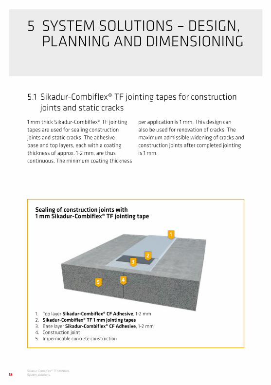
Sealing of construction joints with 1 mm Sikadur-Combiflex® TF jointing tape
Sikadur-Combiflex® TF MANUALSystem solutions18
5.1 Sikadur-Combiflex® TF jointing tapes for construction joints and static cracks
1 mm thick Sikadur-Combiflex® TF jointing tapes are used for sealing construction joints and static cracks. The adhesive base and top layers, each with a coating thickness of approx. 1-2 mm, are thus continuous. The minimum coating thickness
5 SYSTEM SOLUTIONS – DESIGN, PLANNING AND DIMENSIONING
1. Top layer Sikadur-Combiflex® CF Adhesive, 1-2 mm2. Sikadur-Combiflex® TF 1 mm jointing tapes 3. Base layer Sikadur-Combiflex® CF Adhesive, 1-2 mm4. Construction joint5. Impermeable concrete construction
per application is 1 mm. This design can also be used for renovation of cracks. The maximum admissible widening of cracks and construction joints after completed jointing is 1 mm.
3
45
2
1

19Sikadur-Combiflex® TF MANUAL
System solutions
Proof of usability and dimensioningUse is based on the German Approval Certificate (abP) for external strip-form sealing of construction joints and control joints for components made of concrete with high water penetration resistance. The German Approval Certificate is based on a function test acc. PG FBB with a joint widening of 1 mm and a test pressure of 5 bar (50 m water head).
Scope of use and application limits according to the German Approval Certificate• Joint widening up to 1 mm • Damp earth, seepage and perma-
nent water pressure up to 2 bar (20 m water head)
The table below is an aid to dimensioning the minimum bond width (a) per joint side. Ensure position is exactly centrally above the joint (in accordance with the usual construction tolerances).
Construction joint with 1 mm jointing tapes
Non-pressing water Pressing water
< 0.3 bar (3 m WH) ≤ 2 bar (20 m WH)
Tape thickness 1 mm 1 mm 1 mm
Minimum adhesive width (a) per joint side
≥ 50 mm1) ≥ 75 mm1) ≥ 100 mm1)
1) In the case of butt and bearing joints of precast elements, include the grouted joint width in the calculation. The minimum adhesive width starts from the adhesive surface on the precast element.
Syst
em d
escr
iptio
nOp
port
uniti
es fo
r use
Syst
em co
mpo
nent
sM
ater
ial p
rope
rtie
sSy
stem
sol
utio
nsPr
oces
sing
Wel
ding
Deta
il so
lutio
ns fo
r pre
fabr
icat
ed b
asem
ent

sealing strip width
5-10 mmoverlap
Sealing of construction joints based on the example of a precast basement
Sikadur-Combiflex® TF MANUALSystem solutions20
5.1 Jointing tapes for sealing construction joints and static cracks

21Sikadur-Combiflex® TF MANUAL
System solutions
5.2 Sikadur-Combiflex® TF jointing tapes for bonding of expansion joints
2 mm thick Sikadur-Combiflex® TF jointing tapes are used for sealing expansion joints. In this process the adhesive base and top layer are omitted from the joint area to form an exposed expansion part. In the adjacent bonding areas the adhesive base and top layer are designed with a coating thickness of 1-2 mm each. The minimum coating thickness per application is 1 mm.
Sealing of expansion joints with 2 mm Sikadur-Combiflex® TF jointing tapes
1. Adhesive-free expansion range2. Top layer Sikadur-Combiflex® CF Adhesive, 1-2 mm3. Sikadur-Combiflex® TF 2 mm jointing tapes4. Base layer Sikadur-Combiflex® CF Adhesive, 1-2 mm5. Expansion joint with joint insert6. Impermeable concrete construction
4
56
3
1 2
Syst
em d
escr
iptio
nOp
port
uniti
es fo
r use
Syst
em co
mpo
nent
sM
ater
ial p
rope
rtie
sSy
stem
sol
utio
nsPr
oces
sing
Wel
ding
Deta
il so
lutio
ns fo
r pre
fabr
icat
ed b
asem
ent

Sikadur-Combiflex® TF MANUALSystem solutions22
Proof of usability and dimensioningThe use is based on the German Approval Certificate (abP) for external strip-form sealing of expansion joints for components made of concrete with high water penetration resistance. The German Approval Certificate is based on a function test acc. PG FBB Part 2 with a resulting deformation of 20 mm and a test pressure of 3.5 bar (35 m WH). For joints with greater resulting deformations, a function test was carried out with 40 mm resulting deformation and 2.5 bar water pressure.
Scope of use and application limits according to the German Approval Certificate• Resulting deformation
Vres up to 20 mm • Damp earth, seepage and perma-
nent water pressure up to 0.7 bar (7 m water head)
The table below is an aid to dimen-sioning the minimum adhesive width (a) per joint side and minimum width of the adhesive-free expansion part (b). Ensure position is exactly centrally above the joint (in accordance with the usual construction tolerances).
Expansion joint with 2 mm jointing tapes
Non-pressing water
Pressing water
< 0.3 bar (3 m depth) ≤ 0.7 bar (7 m depth)
Thickness of the jointing tape ≥ 2 mm ≥ 2 mm ≥ 2 mm
Minimum adhesive width (a) per joint side
≥ 75 mm ≥ 100 mm ≥ 125 mm
Width of the adhesive-free expansion range
The maximum admissible deformation of the unused expansion range is 40 % of the un-bonded zone. Adhesive-free expansion area (b) including joint width (Wnom):
Expansion ≤ 10 mm 1) ≥ 25 mm ≥ 25 mm2) ≥ 25 mm2)
Expansion ≤ 20 mm 1) ≥ 50 mm ≥ 50 mm2) ≥ 50 mm2)
1) The application limit for resulting deformation is 20 mm acc. to the German Approval Certificate. Greater resulting deformations can be accommodated as required by forming a wider adhesive-free expansion part and looping the strip. This application however no longer complies with the German Approval Certificate. It must be carried out as a special application with individual approval and agreed separately with the building owner.
2) In the case of water pressure, the strip must be supported in the expansion joint with an appropriate joint filler (positive water pres-sure) or by a drag plate construction (negative water pressure) to prevent bowing or swelling of the jointing tape.
5.2 Sikadur-Combiflex® TF jointing tapes for bonding of expansion joints

(a)
(b)
(a)
Wnom
Wnom
(b)
Sealing an expansion joint
23Sikadur-Combiflex® TF MANUAL
System solutions
Syst
em d
escr
iptio
nOp
port
uniti
es fo
r use
Syst
em co
mpo
nent
sM
ater
ial p
rope
rtie
sSy
stem
sol
utio
nsPr
oces
sing
Wel
ding
Deta
il so
lutio
ns fo
r pre
fabr
icat
ed b
asem
ent

Sealing of expansion joints with Sikadur-Combiflex® TF profiles LFT 240 and LFT 330
Sikadur-Combiflex® TF MANUALSystem solutions24
5.3.1 LFT 240 and LFT 330 – double-sided adhesive waterbar profiles
Like the jointing tapes described above, LFT waterbar profiles are also used for retrospective sealing of expansion joints. However, unlike jointing tapes, these profiles feature a formed expansion bulb and a material thickness of 4 mm. They therefore offer high safety reserves under high loads.Here again, the expansion part must be kept free of the adhesive layer. In the bonding areas the adhesive base and top layer are designed with a coating thickness of 1-2 mm each. The minimum coating thickness per application is 1 mm.
1. Adhesive-free expansion area with formed expansion hose2. Top layer Sikadur-Combiflex® CF Adhesive, 1-2 mm3. Sikadur-Combiflex® TF profiles LFT 240 or LFT 3304. Base layer Sikadur-Combiflex® CF Adhesive, 1-2 mm5. Expansion joint with joint insert6. Impermeable concrete construction
5.3 Sikadur-Combiflex® TF waterbar profiles for expansion and connection joints
NOTE:
Temporary fixing with a perforated rail is required for assembly with bonding legs to prevent the waterbar from detaching due to reset forces from the fresh adhesive layer. The perforated rail is inserted before the adhesive top layer and is then completely covered with the adhesive top layer.
4
56
3
1 2

25Sikadur-Combiflex® TF MANUAL
System solutions
Proof of usability and dimensioningThe use is based on/in compliance with the German Approval Certificate (abP) for external strip-form sealing of expansion joints for components made of concrete with high water penetration resistance. The basis for the German Approval Certificate is the function test of the Sikadur-Combiflex® TF jointing tape acc. PG FBB with a resulting deformation of 20 mm and a test pressure of 3.5 bar (35 m WH).
Scope of use and application limits according to the German Approval Certificate• Resulting deformation
Vres up to 20 mm • Damp earth, seepage and perma-
nent water pressure up to 0.7 bar (7 m water head)
The table below is an aid to dimensioning the minimum bond width (a) per joint side. Also in the case of LFT profiles, an adhesive-free expansion part must be formed. The length of the formed expansion bulb generally means there is already an adequate deformation area. This can be enlarged in the event of correspondingly high deformations with a wider gap in the adhesive zone. (cf. specifications for dimensioning the adhesive-free expansion area in chapter 5.2.)
Bonding leg LFT waterbar profiles Pressing water
< 0.3 bar (3 m depth) ≤ 0.7 bar (7 m depth)
Minimum adhesive width (a) per joint side ≥ 10.0 cm1) ≥ 12.5 cm1)
Syst
em d
escr
iptio
nOp
port
uniti
es fo
r use
Syst
em co
mpo
nent
sM
ater
ial p
rope
rtie
sSy
stem
sol
utio
nsPr
oces
sing
Wel
ding
Deta
il so
lutio
ns fo
r pre
fabr
icat
ed b
asem
ent

sealing strip width
ca. 5–10 mmoverlap
joint width
Sealing an expansion joint with an LFT waterbar profile
This configuration can be used for waterproofing on bridge constructions and complies with the specifications of the BASt standard drawing FUG 4 sheet 2.
5.3 Sikadur-Combiflex® TF waterbar profiles for expansion and connection joints
Sikadur-Combiflex® TF MANUALSystem solutions26

27Sikadur-Combiflex® TF MANUAL
System solutions
Sealing of expansion joints with Sikadur-Combiflex® TF profile DFT 330/3
1. Sikadur-Combiflex® TF profile DFT 330/32. Expansion joint with joint insert3. Impermeable concrete construction
5.3.2 DFT 330/3 – waterbar profiles for double-sided concrete embedding
DFT 330/3 waterbar profiles are external waterbar profiles for embedding with in-situ concrete. They have two concreting legs each with 3 anchor ribs, a formed expansion bulb and a material thickness of 4 mm.
3
1
2
Syst
em d
escr
iptio
nOp
port
uniti
es fo
r use
Syst
em co
mpo
nent
sM
ater
ial p
rope
rtie
sSy
stem
sol
utio
nsPr
oces
sing
Wel
ding
Deta
il so
lutio
ns fo
r pre
fabr
icat
ed b
asem
ent

Waterbar profile DFT 330/3 in combination with DFT 330/3KI in the renovation of an existing structure
5.3 Sikadur-Combiflex® TF waterbar profiles for expansion and connection joints
Sikadur-Combiflex® TF MANUALSystem solutions28
Proof of usability and dimensioningOperation and application of the Sikadur-Combiflex® TF profile DFT 330/3 takes place in accordance with DIN 18197 “Sealing of joints in concrete with waterstops”. The profile corresponds in its geometry to the specifications of DIN 18541 for thermoplastic waterbars. The form and dimensions are identical with the DA 320 profiles listed there, with a profile height of 30 mm.
Application limits in accordance with dimension diagrams of DIN 18197• Resulting deformation
Vres up to 20 mm • Damp earth, seepage and perma-
nent water pressure up to 0.7 bar (7 m water head)

29Sikadur-Combiflex® TF MANUAL
System solutions
Sealing of expansion joints with Sikadur-Combiflex® TF profile DFT 330/3 KF
1. Base layer Sikadur-Combiflex® CF Adhesive, 1-2 mm2. Sikadur-Combiflex® TF profile DFT 330/3 KF3. Top layer Sikadur-Combiflex® CF Adhesive, 1-2 mm4. Expansion joint with joint insert5. Impermeable concrete construction
5.3.3 DFT 330/3 KF, KI, KA – waterbar profiles with single sided adhesive and concreting leg for connection joints New to Existing
DFT KF, KI and KA are waterbar profiles with a bonding leg on one side for sealing on existing components and a concreting leg on the other side for casting into new insitu concrete. They can be used with great flexibility for connection joints to existing components and are an economical alternative to clamped constructions. The profiles have a formed expansion bulb and a material thickness of 4 mm. In the bonding areas the adhesive base and top layer are designed with a coating thick-ness of 1-2 mm each. The minimum coating thickness per application is 1 mm.
4
5
3
1
2
NOTE:
Temporary fixing with a perforated rail is required for assembly with bonding legs to prevent the waterbar from detaching due to reset forces from the fresh adhesive layer. The perforated rail is inserted before the adhesive top layer and is then completely covered with the adhesive top layer (see also Processing section).
Syst
em d
escr
iptio
nOp
port
uniti
es fo
r use
Syst
em co
mpo
nent
sM
ater
ial p
rope
rtie
sSy
stem
sol
utio
nsPr
oces
sing
Wel
ding
Deta
il so
lutio
ns fo
r pre
fabr
icat
ed b
asem
ent
5.3 Sikadur-Combiflex® TF waterbar profiles for expansion and connection joints
Sikadur-Combiflex® TF MANUALSystem solutions30
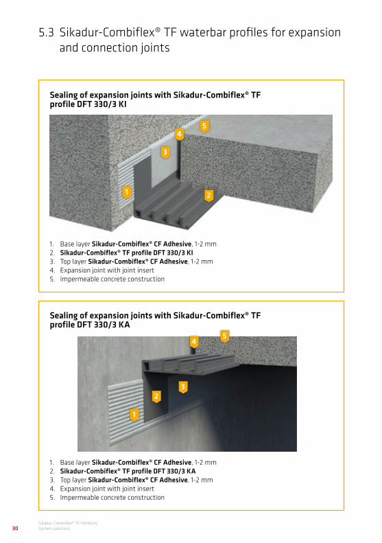
Sealing of expansion joints with Sikadur-Combiflex® TF profile DFT 330/3 KI
Sealing of expansion joints with Sikadur-Combiflex® TF profile DFT 330/3 KA
1. Base layer Sikadur-Combiflex® CF Adhesive, 1-2 mm2. Sikadur-Combiflex® TF profile DFT 330/3 KI3. Top layer Sikadur-Combiflex® CF Adhesive, 1-2 mm4. Expansion joint with joint insert5. Impermeable concrete construction
1. Base layer Sikadur-Combiflex® CF Adhesive, 1-2 mm2. Sikadur-Combiflex® TF profile DFT 330/3 KA3. Top layer Sikadur-Combiflex® CF Adhesive, 1-2 mm4. Expansion joint with joint insert5. Impermeable concrete construction
45
3
1 2
45
3
1
2

31Sikadur-Combiflex® TF MANUAL
System solutions
Sealing a connection joint to an existing structure with a profile type DFT 330/3 Kl
Proof of usability and dimensioningIn the case of Sikadur-Combiflex® TF profiles DFT 330/3 KF, KI and KA, differentiation is made between bonding and concreting legs.
Bonding leg:The use is based on/in compliance with the German Approval Certificate (abP) for external strip-form sealing of expansion joints for components made of concrete with high water penetration resistance. The basis for the German Approval Certificate is the function test of the Sikadur-Combiflex® TF jointing tape acc. PG FBB with a resulting deformation of 20 mm and a test pressure of 3.5 bar (35 m WH).
Concreting leg:Use and application is in accordance with DIN 18197 "Sealing of joints in concrete with waterstops". The profile corresponds in its geometry to the specifications of DIN 18541 for thermoplastic waterbars. The form and dimensions are identical with the DA 320 profiles listed there, with a profile height of 30 mm.
Application limits in accordance with dimension diagrams of DIN 18197• Resulting deformation
Vres up to 20 mm • Damp earth, seepage and perma-
nent water pressure up to 0.7 bar (7 m water head)
Syst
em d
escr
iptio
nOp
port
uniti
es fo
r use
Syst
em co
mpo
nent
sM
ater
ial p
rope
rtie
sSy
stem
sol
utio
nsPr
oces
sing
Wel
ding
Deta
il so
lutio
ns fo
r pre
fabr
icat
ed b
asem
ent
5.3 Sikadur-Combiflex® TF waterbar profiles for expansion and connection joints
Sikadur-Combiflex® TF MANUALSystem solutions32
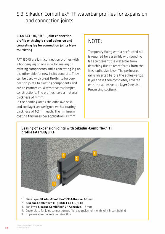
Sealing of expansion joints with Sikadur-Combiflex® TF profile FAT 130/3 KF
1. Base layer Sikadur-Combiflex® CF Adhesive, 1-2 mm2. Sikadur-Combiflex® TF profile FAT 130/3 KF3. Top layer Sikadur-Combiflex® CF Adhesive, 1-2 mm4. Cover plate for joint connection profile, expansion joint with joint insert behind5. Impermeable concrete construction
5.3.4 FAT 130/3 KF – joint connection profile with single sided adhesive and concreting leg for connection joints New to Existing
FAT 130/3 are joint connection profiles with a bonding leg on one side for sealing on existing components and a concreting leg on the other side for new insitu concrete. They can be used with great flexibility for con-nection joints to existing components and are an economical alternative to clamped constructions. The profiles have a material thickness of 4 mm. In the bonding areas the adhesive base and top layer are designed with a coating thickness of 1-2 mm each. The minimum coating thickness per application is 1 mm.
NOTE:
Temporary fixing with a perforated rail is required for assembly with bonding legs to prevent the waterbar from detaching due to reset forces from the fresh adhesive layer. The perforated rail is inserted before the adhesive top layer and is then completely covered with the adhesive top layer (see also Processing section).
4 5
3
1
2

33Sikadur-Combiflex® TF MANUAL
System solutions
Proof of usability and dimensioningIn the case of the Sikadur-Combiflex® TF profile FAT 130/3 KF a distinction is made between the bonding leg and the concreting leg.
Bonding leg:The use is based on/in compliance with the German Approval Certificate (abP) for external strip-form sealing of expansion joints for components made of concrete with high water penetration resistance. The basis for the German Approval Certificate is the function test of the Sikadur-Combiflex® TF jointing tape acc. PG FBB with a resulting deformation of 20 mm and a test pressure of 3.5 bar (35 m WH).
Concreting leg:Use and application is in accordance with DIN 18197 "Sealing of joints in concrete with waterstops". Cover plate and concreting leg of the profile correspond in terms of geometry to the specifications of the FA130 profiles given in DIN 18541 Thermoplastic waterbars.
Sealing a connection joint on an existing structure with FAT130/3 KF profile
Application limits in accordance with dimension diagrams of DIN 18197• Resulting deformation
Vres up to 20 mm • Damp earth, seepage and perma-
nent water pressure up to 0.3 bar (3 m water head)
Syst
em d
escr
iptio
nOp
port
uniti
es fo
r use
Syst
em co
mpo
nent
sM
ater
ial p
rope
rtie
sSy
stem
sol
utio
nsPr
oces
sing
Wel
ding
Deta
il so
lutio
ns fo
r pre
fabr
icat
ed b
asem
ent

Sikadur-Combiflex® TF MANUALSystem solutions34
Sealing a transition on a steel component with the Sikadur-Combiflex® TF System
Material transitions and connections to embedded parts can also be flexibly sealed with the Sikadur-Combiflex® TF System. A frequently-used example here is the connection to steel construction components e.g. beams or steel sheet piles. Attention must be paid, in relation to the necessary substrate preparation, to the respective material of the connection surface in transitions and connections. This can be taken from Section 6.1. "Substrate".Depending on the construction, material and expected deformation, the configura-tion corresponding must be conceived as construction or expansion joints and dimen-sioned according to the respective chapters.
5.4 Connections and material transitions
NOTE:
The German Approval Certificate of the Sikadur-Combiflex® TF System is exclusively for sealing on concrete. All other bonding substrates represent a special application and require individu-al consent.
35Sikadur-Combiflex® TF MANUAL
System solutions
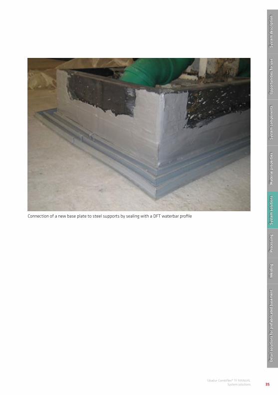
Connection of a new base plate to steel supports by sealing with a DFT waterbar profile
Syst
em d
escr
iptio
nOp
port
uniti
es fo
r use
Syst
em co
mpo
nent
sM
ater
ial p
rope
rtie
sSy
stem
sol
utio
nsPr
oces
sing
Wel
ding
Deta
il so
lutio
ns fo
r pre
fabr
icat
ed b
asem
ent

Sikadur-Combiflex® TF MANUALSystem solutions36
For penetrations, e.g. pipes the same applies, in principle, as the material transitions and connections as shown above. Pipes can also be easily sealed with the Sikadur-Combiflex® TF System. To this end, a well-fitting collar is produced from the membrane of a 2 mm jointing tape by thermal forming and welding (cf. Welding / shaped parts chapter). This is then
adhered around the pipe with the Sikadur-Combiflex® CF Adhesive.Attention must be paid to the necessary substrate preparation of the respective pipework material. See section 6.1. "Substrate".
5.5 Penetrations
Sealing a pipe penetration with the Sikadur-Combiflex® TF System

37Sikadur-Combiflex® TF MANUAL
System solutions
Sealing of pipe penetrations in different dimensions and materials
Syst
em d
escr
iptio
nOp
port
uniti
es fo
r use
Syst
em co
mpo
nent
sM
ater
ial p
rope
rtie
sSy
stem
sol
utio
nsPr
oces
sing
Wel
ding
Deta
il so
lutio
ns fo
r pre
fabr
icat
ed b
asem
ent
Sikadur-Combiflex® TF MANUALSystem solutions38
Elastic sealing systems must be protected against mechanical damage to guarantee a permanent sealing function. In the case of construction joints this is carried out with a complete top layer of cured system adhesive.
Expansion joints require additional protection of the jointing tape and/or the exposed expansion area against any damage.
Here, the following factors must be taken into consideration:
1. Protection against mechanical damage:This relates to all direct damage to the exposed expansion area or damage over a certain period of time. This includes for example:• Traffic-able expansion joints• Directly trafficked expansion joints, e.g.
Expansion joints in transitions between underground car parks and stairwells
• Expansion joints in sewage treatment plant with protection by steel plate
• Flow with abrasive media • Earth-filled expansion joints without
thermal insulation
These joints require a corresponding protective construction. While with earth-filled expansion joints the installation of a perimeter insulation plate is adequate, protection plate constructions are required for all other examples. The protection plate construction must be dimensioned such that it can absorb all incoming loads without damage and disperse them throughout the component. Furthermore the fixing of the protection plate construction must be designed such that the joint can continue to move unhindered (e.g. angle mounting, slot mounting etc.).
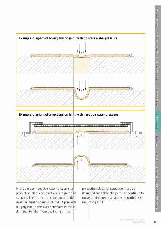
2. Protection against damage from water pressure:The elastic material properties of the jointing tape with water pressure in expansion joints also requires the use of a sub-construction. This should prevent the swelling of the exposed adhesive-free expansion area and so avoid the increased risk of damage. In the case of positive water pressure, the support function is carried out by the joint insert. This must extend to the edge of the joint in order to support the jointing tape directly.
5.6 Protection and support structures in the case of mechanical load or negative water pressure
39Sikadur-Combiflex® TF MANUAL
System solutions
In the case of negative water pressure, a protection plate construction is required as support. The protection plate construction must be dimensioned such that it prevents bulging due to the water pressure without damage. Furthermore the fixing of the
protection plate construction must be designed such that the joint can continue to move unhindered (e.g. angle mounting, slot mounting etc.).
Example-diagram of an expansion joint with positive water pressure
Example-diagram of an expansion joint with negative water pressure
Syst
em d
escr
iptio
nOp
port
uniti
es fo
r use
Syst
em co
mpo
nent
sM
ater
ial p
rope
rtie
sSy
stem
sol
utio
nsPr
oces
sing
Wel
ding
Deta
il so
lutio
ns fo
r pre
fabr
icat
ed b
asem
ent

Sikadur-Combiflex® TF MANUALSystem solutions40
Protection cover with slot construction in a clarifier
Protection plate construction with slot mounting as protective or support construction with expansion joints
5.6 Protection and support structures in the case of mechanical load or negative water pressure

41Sikadur-Combiflex® TF MANUAL
System solutions
The Sikadur-Combiflex® TF System can also be used in the renovation of water ingress and joints. Joint sealing is also possible owing to the availability of up to 2m wide joining tapes. The system is also suitable for the repair of individual damaged and leaking surfaces e.g. as new inner trough in a basement. Dimensioning is the same in principle as described above for construction, control and expansion joints.
Load condition, negative water pressureIt is important and worth noting, that the load condition of negative water pressure does not fall under planning rules in Germany and must therefore be agreed with the building owner as a special case in the context of renovation. For this reason, negative water pressures are also not included in the German Approval Certificates.
5.7 Waterproofing in renovation projects
Sealing of cracks
The Sikadur-Combiflex® TF System has nevertheless been successfully tested in the context of functional tests with negative water pressure. Thus, we have proof of function for this application and this is available as a test report.When using expansion joints the arrangement of a supporting construction according to the previous chapter must be taken into consideration.
Syst
em d
escr
iptio
nOp
port
uniti
es fo
r use
Syst
em co
mpo
nent
sM
ater
ial p
rope
rtie
sSy
stem
sol
utio
nsPr
oces
sing
Wel
ding
Deta
il so
lutio
ns fo
r pre
fabr
icat
ed b
asem
ent

Renovation of an expansion joint - in this case a supporting structure by means of drag plate flashing is required.
Sikadur-Combiflex® TF MANUALSystem solutions42
Jointing sealing construction as new inner trough for the renovation of an existing basement
Renovation of a leaking construction joint
5.7 Waterproofing in renovation projects

43SikaProof® MANUAL
Performance specification texts
The Sikadur-Combiflex® TF System is also used in combination with the SikaProof fully bonded membrane system, as an important component of the below ground waterproofing system. The combination of the two systems successfully achieves watertightness up to 5 bar (50 m head) in function tests. Thus, a permanently dependable connection and transition is ensured.
In the combination of the two systems the Sikadur-Combiflex® TF jointing on the outside of SikaProof® (FPO membrane) is connected by a adhered overlap. In order to guarantee adequate bonding of the epoxy resin adhesive to the FPO membrane, this must be correspondingly prepared. The
5.8 Use in combination with SikaProof® fresh concrete composite system
Sikaproof membrane in the connection area must be clean, dry and free from all adhesion-reducing substances. Depending on the local circumstances, it must also be cleaned corresponding before use. The substrate is prepared by short-term flame treatment of the Sikaproof membrane. Hot air preparation is insufficient. The plastic surface must be prepared by playing the open flame over the surface of the Sikaproof membrane. Ensure that the open flame contacts the Sikaproof membrane only briefly (keep flame moving) and the membrane is not damaged by over-long heat application.
Syst
em d
escr
iptio
nOp
port
uniti
es fo
r use
Syst
em co
mpo
nent
sM
ater
ial p
rope
rtie
sSy
stem
sol
utio
nsPr
oces
sing
Wel
ding
Deta
il so
lutio
ns fo
r pre
fabr
icat
ed b
asem
ent

Sikadur-Combiflex® TF MANUALSystem solutions44
It can then be connected directly to the SikaProof® with the Sikadur-Combiflex® CF system adhesive.
When producing the joint, ensure that the SikaProof® surface is not laid directly up to the joint flank but is somewhat set back. An exposed concrete edge zone of at least 50 mm must be allowed on both sides of the joint. The Sikadur-Combiflex® TF System will be applied in strips later and connected overlapping to the adjacent SikaProof® surface. The overlap should be at least 25 mm.
5.8 Use in combination with SikaProof® fresh concrete composite system

Combination of Sikadur-Combiflex® TF System with the SikaProof® fresh concrete composite system in the concrete slab
Combination of Sikadur-Combiflex® TF System with the SikaProof® membrane on concrete slab and wall.
45Sikadur-Combiflex® TF MANUAL
System solutionsSikaProof® MANUAL
Performance specification texts
Syst
em d
escr
iptio
nOp
port
uniti
es fo
r use
Syst
em co
mpo
nent
sM
ater
ial p
rope
rtie
sSy
stem
sol
utio
nsPr
oces
sing
Wel
ding
Deta
il so
lutio
ns fo
r pre
fabr
icat
ed b
asem
ent

Sikadur-Combiflex® TF MANUALProcessing46
6 USE OF THE SYSTEM
6.1 Substrate requirements
The substrate must be clean and firm and should be free of any separating substances e.g. dust, dirt, form oil and bond-reducing components. In case of doubt, abraid down the substrate in the bond area or clean with a wire brush. Penetrating processing (exposure of the maximum aggregate size) is not required. Ensure that in cooler weather the component temperature is not less than the admissible processing temperature. The substrate should be as dry as possible. For this reason, it is recommended to dry the substrate by flame treatment if necessary. Subsequent jointing is the considerably sim-plified. Matt-damp substrates are possible,
but require particularly careful application. The system adhesive must be firmly incor-porated into the surface structure at appli-cation. If processed correspondingly there is no qualitative distinction between bonding on dry or matt-damp substrates. Application when the substrate exhibits standing water is not permitted and should be avoided in all cases. In such cases the substrate must be free from any standing water. In the case of constantly flowing moisture (e.g. in the case of water-bearing cracks), additional measures for temporary water stopping are required until the system adhesive has reached sufficient strength.

47Sikadur-Combiflex® TF MANUAL
Processing
Bonding substrates must feature the fol-lowing characteristics:• Adequately firm and loadbearing,
minimum bond tensile strength of 1.5 N/mm²• Take into consideration the minimum
component temperature • Clean and free of contamination, which
can prevent or reduce adhesion (e.g. release agent, oils, grease, fuels etc.);
• Free from loose or friable particles such as sand, silt, dust and dirt etc.
IMPORTANT NOTE:
The Sikadur-Combiflex® TF System is designed for jointing on concrete substrates. Testing and proof of fitness for use in the form of the German Approval Certificate stipulates exclusively application on concrete substrates.
The outstanding bonding characteris-tics of the system adhesive mean that the system can nevertheless also be used on a variety of other substrates. In such case it is essential to under-stand that these are special applica-tions and thus fall outside the German Approval Certificate. The substrate must be impermeable to ensure com-plete water tightness across the joint. In this case additional adjacent flat sealing must be provided.
Syst
em d
escr
iptio
nOp
port
uniti
es fo
r use
Syst
em co
mpo
nent
sM
ater
ial p
rope
rtie
sSy
stem
sol
utio
nsPr
oces
sing
Wel
ding
Deta
il so
lutio
ns fo
r pre
fabr
icat
ed b
asem
ent

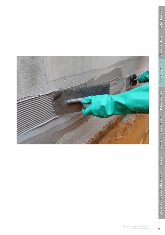
Substrate preparation by grinding the concrete surfaces
Sikadur-Combiflex® TF MANUALProcessing48
Concrete (standard application)Concrete substrates must be mechanically prepared, by e.g. grinding, milling, bead or sand blasting. All loose layers, plaster or paints must be removed. The adhesive surfaces must be freed from all dust and separating contamination. Recesses and voids must be reprofiled with appropriate concrete repair systems.
6.2 Substrate preparation

49Sikadur-Combiflex® TF MANUAL
Processing
Special applications on deviating substratesThe system adheres to nearly all mineral substrates. Good adhesion is also achieved on metals and many plastics. The following substrate preparations are simply general recommendations based on our experience. It is recommended to test and assess any deviating substrates in each case before application.
SteelThe substrate pretreatment must comply with standard degree of purity SA 2 ½. All interfering and separating substances must be completely removed (e.g. grease from the rollers). These can be carried out for example by grinding with a roughing disc.
When applying to steel substrates, please pay particular attention to the surface temperature. Steel surfaces heat up considerably under the influence of sunlight and cause enormous shear stresses due to the temperature-related reaction acceleration of the epoxy resin adhesive. In summer therefore, freely weathered components exposed to the sun should therefore be applied early in the morning or shaded artificially. The steel substrate may not be heated by sunlight at the time of the application.
PlasticsMost plastics can be prepared by roughening and grinding the surface. This includes e.g. standard commercial drainpipes. PE surfaces (e.g. water pipes) must be briefly flame treated prior to application.
Existing foor coatingsAdhesive can be applied to epoxy resin-based floor coatings after cleaning and grinding of the existing coating. For further bonding primer coatings, carry out a test bond or contact your authorised advisor.
Sealing of a GRP pipe penetration
NOTE:
It is basically recommended, in the case of deviating or unknown bonding substrates, to carry out a trial bond to assess the adhesiveness of the substrate.
Syst
em d
escr
iptio
nOp
port
uniti
es fo
r use
Syst
em co
mpo
nent
sM
ater
ial p
rope
rtie
sSy
stem
sol
utio
nsPr
oces
sing
Wel
ding
Deta
il so
lutio
ns fo
r pre
fabr
icat
ed b
asem
ent

Sikadur-Combiflex® TF MANUALProcessing50
The Sikadur-Combiflex® TF System may only be applied in dry weather. Matt-damp substrates are possible, provided there is nohydrostatic pressure (see Substrate chapter).
The processing temperatures are determined by the application limits of the system adhesive and must be complied with at all costs. Processing temperatures relate to the environment, and component temperatures!
The standard processing temperature for the Sikadur-Combiflex® TF system is between +10 and +30°C.
Technically the system can still be used in temperatures below +10 °C, though careful handling is advised and the following must be observed, note:
• use at this temperature range requires particular care to manage the existing risks. Success depends on manual preparation and correct assessment of the situation. Application is at the risk and guarantee of the user.
• The absolute minimum technical process-ing limit of the system is +2 °C compo-nent and ambient temperature (function of adhesive reaction). To be able to guar-antee this reliably, we recommend use of the system ≥ +5 °C (this guarantees a specific tolerance because temperatures can never be exactly predicted).
• The applied system must be kept frost-free for the first 72 hours (if required, provide weather protection or heating mats).
• Store and preheat processing materials in heated site containers.
6.3 Temperature and weathering
Processing temperature
Standard processing range + 10 to +30°C
Processing area with special measures
Recommended: + 5 to + 10°C(minimum functional limit for adhesive reaction: ≥ + 2°C)

In the summer months, clean work preparation is particularly important. Start bonding only when all necessary preparations have been made
51Sikadur-Combiflex® TF MANUAL
Processing
Epoxy resin-based adhesives react temperature dependently. The higher the temperature, the faster the response time. This means that the material temperature of the adhesive during the processing should be influenced positively as far as possible – in the summer, protect against heat and avoid direct sunlight and in winter store in a controlled temperature as far as possible (e.g. heated container).
Furthermore, in the summer months work preparation and work sequences must be planned well in advance. Carry out all preparatory work prior to bonding. Only after the substrate is prepared, i.e. adhesive edges bonded with tape, shaped parts welded and formed and all materials and tools ready, should you start to mix the adhesive. Process this quickly immediately after mixing and finish applying the system.
Syst
em d
escr
iptio
nOp
port
uniti
es fo
r use
Syst
em co
mpo
nent
sM
ater
ial p
rope
rtie
sSy
stem
sol
utio
nsPr
oces
sing
Wel
ding
Deta
il so
lutio
ns fo
r pre
fabr
icat
ed b
asem
ent

Sikadur-Combiflex® TF MANUALProcessing52
Pot life(Pot life 200g)
+ 10 °C approx. 125 min
+ 23 °C approx. 50 min
+ 30 °C approx. 25 min
Pot life of Sikadur-Combifex® CF Adhesive:
Sikadur-Combiflex® CF Adhesive is a two-component epoxy resin-based adhesive in a double container. Add all of component B to component A to mix. Mix with electric hand mixer (resin mortar mixing paddle) for at least 3 minutes at low speed (max. 500 rpm), until there are no longer any traces of colour marbling in the mix, at the base or around the edges of the container. A homogenous grey mass must result. Decant mixture into a clean vessel and mix again for at least 1 minute. Mix at low speed in order to introduce as little air as possible (max. 500 rpm.).
6.4 Mixing the system adhesive
Epoxy resin adhesives react temperature dependently. It is recommended to use the mixed adhesive immediately. For this rea-son, all preparatory work must be completed before mixing. Mix only as much as can be used within the pot life. The pot life starts with the mixing. It is shorter, the higher the temperature and the larger the quantity mixed. To achieve longer open times at high temperatures, divide the components into portions or use smaller containers. Another method is to cool the individual components A and B before mixing (not less than + 5 °C).
Separate double container. Open the container carefully with pliers (use the breakaway line on the snap ring).
Mixing the system adhesive
1 2

53Sikadur-Combiflex® TF MANUAL
Processing
Cleaning of toolsClean any adhesive residue off tools while still wet with Sika-Colma cleaner. Once hardened, material can only be removed mechanically (or with heat treatment).
Use appropriate mixing paddle to stir in epoxy resin adhesive.
Mix system adhesive at low speed for at least 3 minutes (max. 500 rpm.).
Decant mixture into a clean vessel.
Add component B to component A.
Ensure that both materials are completely blended, including on the container edge and on the bottom.
Stir for 1 more minute and check that the compound is completely blended. The adhesive is then ready to use and should be applied as soon as possible.
3
5
7
4
6
8Sy
stem
des
crip
tion
Oppo
rtun
ities
for u
seSy
stem
com
pone
nts
Mat
eria
l pro
pert
ies
Syst
em s
olut
ions
Proc
essi
ngW
eldi
ngDe
tail
solu
tions
for p
refa
bric
ated
bas
emen
t

Sikadur-Combiflex® TF MANUALProcessing54
The values given are purely mathematical/calculated and represent the optimum case. They are intended only as a guide. Effective use depends on the surface roughness, wastage, application widths and installation situation. The actual adhesive consumption can vary considerably and this must be taken into consideration during the work preparation.
6.5 Adhesive consumption
Calculated adhesive consumption, Sikadur-Combifex® CF Adhesive with 2 mm base layer 2 mm top layer
Bond width per joint side in cm Total bond width in cm Consumption
5.0 10.0 approx. 0.7 kg/m
7.5 15.0 approx. 1.1 kg/m
10.0 20.0 approx. 1.4 kg/m
12.5 25.0 approx. 1.8 kg/m
Note: The values given include exclusively the precise bond width with 2 mm each base layer and top layer. When processing waterbar profiles, increased consumption must be taken into consideration to allow for the complete coverage of the perforated rail!

55Sikadur-Combiflex® TF MANUAL
Processing
1. If there are traces of the Sikadur-Combifex® TF jointing tape (e.g. in connection areas or left-over rollers), these should be cleaned in advance with wet or dry cloths. Use only water for cleaning (no solvents) and then dry. Check the Sikadur-Combiflex® TF jointing tapes for damage from storage or transport and remove damaged areas if required.
2. Take into consideration substrate preparation acc. "Substrate" chapter.
3. Create shaped parts, hot air welding – cf. "Welding" chapter.
6.6 Application of jointing tapes
Prepare substrate by grinding with concrete grinding disc
Producing shaped parts and welds
4. Sealing in visible areas: Apply tape along the side edge of the sealing corresponding to the planned bond width. This can be removed later, after the adhesive top layer is applied but still in fresh state. This enables a clean, even and straight bond edge.
Apply tape to the edge of the sealing in the visible areas
2 4
3
Syst
em d
escr
iptio
nOp
port
uniti
es fo
r use
Syst
em co
mpo
nent
sM
ater
ial p
rope
rtie
sSy
stem
sol
utio
nsPr
oces
sing
Wel
ding
Deta
il so
lutio
ns fo
r pre
fabr
icat
ed b
asem
ent

Sikadur-Combiflex® TF MANUALProcessing56
5. Base layer with the system adhesive: Apply the mixed system adhesive Sikadur-Combiflex® CF Adhesive evenly to the substrate with the aid of a 4 mm toothed trowel. In the case of matt-damp substrates the system adhesive must be incorporated forcibly into the porous structure of the surface.
Coating thickness of the base layer:1 to 2 mm
Minimum application width:According to specifications for dimensioning the bond width (see "System solutions" chapter)
In the case of construction joints:Apply system adhesive thoroughly to the whole surface of the construction joint.
In the case of expansion joints:Omit system adhesive from the joint/expansion area. The width of the adhesive-free expansion area comes from the dimensioning specifications (see "System solutions" chapter). It is recommended to use tape in a corresponding width as an aid to achieving a clean adhesive edge and to form an even adhesive-free zone, if the exposed area is wider than the joint chamber.
Complete base layer of system adhesive with a 4 mm notched trowel in the area of construction or element wall joints
Base layer of system adhesive with 4 mm notched trowel in the case of an expansion joint
6.6 Application of jointing tapes
5
5

57Sikadur-Combiflex® TF MANUAL
Processing
6. Incorporation of the Sikadur-Combifex® TF jointing tape: Lay the jointing tapes in the correct position in the fresh base layer within the pot life of the system adhesive. Then press down with a suitable tool (wood block, trowel with rounded edges, solid rubber roller, etc.) from inside to outside, to remove air-bubbles and cavities. The use of the 4 mm toothed trowel means that the thickness of the base layer is sufficient as long as there is a slight material expulsion at the edge when pressing down.Required connections (butt joints, T-pieces etc.) must be produced corresponding to the welding instructions and must be carried out before rolling into the base layer! Areas in which connections and welding are later required must remain free of adhesive. Keep a distance of approx. 500 mm between these areas and the adhesive area.
When producing expansion joints with significant movement the strip can be looped. Do this immediately after inserting jointing tape. If necessary, preform a loop thermally first.
Press adhesive areas to remove any voids with trowel, roller or wood block etc.
Lay the 1 mm jointing tape into the fresh adhesive layer in the area of a construction joint
Lay the 2 mm jointing tape into the fresh adhesive layer near an expansion joint
6
6
6Sy
stem
des
crip
tion
Oppo
rtun
ities
for u
seSy
stem
com
pone
nts
Mat
eria
l pro
pert
ies
Syst
em s
olut
ions
Proc
essi
ngW
eldi
ngDe
tail
solu
tions
for p
refa
bric
ated
bas
emen
t

Sikadur-Combiflex® TF MANUALProcessing58
7. Top layer with the system adhesive: Apply the mixed system adhesive Sikadur-Combiflex® CF Adhesive evenly to the sealing with the aid of a 4 mm toothed trowel. Smooth with a smoothing trowel after applying. A closed adhesive layer must be formed. The edges of the jointing tapes must be completely embedded in the system adhesive.
Coating thickness of the top layer:1 to 2 mm
Minimum application width:Same as the base layer
In the case of construction joints:Apply system adhesive thoroughly to the whole surface of the construction joint.
In the case of expansion joints:Omit system adhesive from the joint/expansion area (as per the base layer). It is recommended to use a tape in the corresponding width as an aid to creating a clean adhesive edge and an even width of adhesive-free zone.
Top layer of the system adhesive in a construction joint
Apply tape to form the expansion area
Apply the top layer of the system adhesive when producing expansion joint
6.6 Application of jointing tapes
CAUTION:
The adhesive-free area of the base and top layer must be congruent!
7
7
7

59Sikadur-Combiflex® TF MANUAL
Processing
8. Peel off tape: Peel off tape at the edges (when sealing in visible areas) and/or expansion areas (when producing expansion joints) straight after applying, while the adhesive is still wet.
Clean the edges of the adhesive and in the expansion joint area.
8
Then peel off tape (within the pot life of the system adhesive)
8
Cleanly produced expansion area of expansion joint sealing
8Sy
stem
des
crip
tion
Oppo
rtun
ities
for u
seSy
stem
com
pone
nts
Mat
eria
l pro
pert
ies
Syst
em s
olut
ions
Proc
essi
ngW
eldi
ngDe
tail
solu
tions
for p
refa
bric
ated
bas
emen
t

Sikadur-Combiflex® TF MANUALProcessing60
10. Sanding the adhesive layer: If coatings or surface waterproofing will later be connected to the jointing tape, sand down when adhesive is fresh with kiln-dried quartz sand.
Sanded adhesive layer for subsequent application of coatings
10
Smoothed top layer in visible area
9
9
9. Smoothing the top layer: When creating a visible sealing, you can smooth the freshly-applied adhesive with a standard medium (soapy water) and a brush.
6.6 Application of jointing tapes

61Sikadur-Combiflex® TF MANUAL
Processing
Preparation of substrate by grinding the subsequent bonding surface
This chapter describes the make-up of the adhesive profiles and/or the application of the bonding leg. Embedded waterbar profiles and/or concreting legs must be used according to the specifications of DIN 18197 "Sealing of joints in concrete with waterstops".
1. If there are traces of the Sikadur-Combifex® TF waterbar profiles (e.g. in connection areas), these should be cleaned in advance with wet or dry cloths. Use only water for cleaning (no solvents) and then dry. Check the Sikadur-Combiflex® TF waterbar profile for damage before using. Replace any damaged profiles.
2. Take into consideration substrate preparation acc. "Substrate" chapter .
3. Produce any necessary welded connec-tions in the form of construction site butt joints or jointing tape connections – cf "Welding" chapter.
4. Sealing in visible areas (may be required e.g. if using LFT-profiles): Apply tape along the side edge of the sealing corresponding to the bond width. This can be removed later, after the adhesive top layer is applied but still in fresh state. This enables a clean, even and straight bond edge.
6.7 Application of waterbar profiles
Produce construction site butt joint
2
3
Syst
em d
escr
iptio
nOp
port
uniti
es fo
r use
Syst
em co
mpo
nent
sM
ater
ial p
rope
rtie
sSy
stem
sol
utio
nsPr
oces
sing
Wel
ding
Deta
il so
lutio
ns fo
r pre
fabr
icat
ed b
asem
ent

Base layer of system adhesive for bonding a DFT water-bar profile
Sikadur-Combiflex® TF MANUALProcessing62
Laying the DFT profile into the adhesive layer
5. Base layer with the system adhesive: Apply the mixed system adhesive Sikadur-Combiflex® CF Adhesive evenly to the substrate with the aid of a 4 mm toothed trowel. In the case of matt-damp substrates the system adhesive must be incorporated forcibly into the porous structure of the surface.
Coating thickness of the base layer:1 to 2 mm
Minimum application width:According to specifications for dimensioning the bond width (see "System solutions" chapter). With profiles, the bonding leg is usually completely glued in. However, you should leave a gap in the adhesive layer of approx. 15 mm to form the expansion bulb.
6. Inlaying the Sikadur-Combifex® TF Waterbar profile: Lay the waterbar profile in the correct position in the fresh base layer within the preparation time of the system adhesive. Then press down with a suitable tool (wood block, trowel with rounded edges, solid rubber roller, etc.) from inside to outside, to remove air-bubbles and cavities. The use of the 4 mm toothed trowel means that the thickness of the base layer is sufficient as long as there is a slight material expulsion at the edge when pressing down.Required welded joints must be produced corresponding to the welding instructions and must be carried out before working into the base layer! Areas in which connections and welding are later required must remain free of adhesive. In the case of waterbar profiles, a gap of at least 1 metre must be maintained from the adhesive area.
6.7 Application of waterbar profiles
5 6

63Sikadur-Combiflex® TF MANUAL
Processing
Reinforcing the DFT waterbar profile with a perforated rail
7. Fixing with perforated rail: In the case of waterbar profiles, the bond must be additionally fixed with a perforated rail . This secures the profile while the adhesive is curing. The material thickness and reset forces otherwise pose a risk of the fresh adhesive layer from coming loose. The perforated rail is simply for additional fixing. The sealing effect is achieved exclusively via the bond.
8. Top layer with the system adhesive: Apply the mixed system adhesive Sikadur-Combiflex® CF Adhesive to the existing sealing and smooth. A closed adhesive layer must be formed. The perforated rail must be completely covered with system adhesive. The edge of the waterbar profile's bonding leg must be completely embedded in the system adhesive.
Coating thickness of the top layer:1 to 2 mm
Minimum application width:Same as the base layer, note: The adhesive-free area of the base and top layer must be equal!
Finished applied DFT waterbar profile
7 8
Syst
em d
escr
iptio
nOp
port
uniti
es fo
r use
Syst
em co
mpo
nent
sM
ater
ial p
rope
rtie
sSy
stem
sol
utio
nsPr
oces
sing
Wel
ding
Deta
il so
lutio
ns fo
r pre
fabr
icat
ed b
asem
ent

Sikadur-Combiflex® TF MANUALProcessing64
LFT waterbar profile in visible area of a bridge coping
9. Sealing in visible areas (may be required e.g. if using LFT-profiles): Peel off tapes from the edges immediately after application, before the system adhesive dries. When creating a visible sealing, you can smooth the freshly-applied adhesive with a standard medium (i.e. soapy water) and a brush.
10. Sanding the adhesive layer: If coatings or surface waterproofing will later be connected to the sealing, sand down when adhesive is fresh with kiln-dried quartz sand.
9
6.7 Application of waterbar profiles

65Sikadur-Combiflex® TF MANUAL
Processing
Backfilling the excavationElastic sealing systems must be protected by suitable means against mechanical damage to guarantee a permanent sealing function. In the case of construction joints this is carried out with a complete adhesive top layer of cured system adhesive.In the case of expansion joints, appropriate filling protection must be provided for the exposed expansion part of the jointing tape. In insulated basement areas this function is performed by the perimeter insulation in front of it. Otherwise, pressure-stable insulation strips must be applied to the area before sealing. Further protective construction options, see also "Protection and construction options…".
In each case, ensure that the excavation is filled according to regulations with appropriate back-filling material. Filling may only take place after adequate hardening of the system adhesive Sikadur-Combiflex® CF Adhesive. The corresponding minimum hardening time is temperature dependent, which must be taken into consideration. The assessment must be carried out in accordance with the average component temperatures. Component temperatures under 2°C must be excluded for the purposes of the curing time. Furthermore, the system must be kept frost-free for the first 72 hours (use weather protection or heating mats if necessary).
6.8 Backfilling and loading of the system
filling protection
thermal insulation
filling protection
thermal insulation
Filling protection of the expansion joint sealing through perimeter insulation
Syst
em d
escr
iptio
nOp
port
uniti
es fo
r use
Syst
em co
mpo
nent
sM
ater
ial p
rope
rtie
sSy
stem
sol
utio
nsPr
oces
sing
Wel
ding
Deta
il so
lutio
ns fo
r pre
fabr
icat
ed b
asem
ent

Sikadur-Combiflex® TF MANUALProcessing66
Earliest filling date depending on the component temperature
7
6
5
4
3
2
1
02 5 10 15 20
Component temperature in °C
Curin
g ti
me
in d
ays
Earliest filling date
6.8 Backfilling and loading of the system

67Sikadur-Combiflex® TF MANUAL
Processing
Complete loading of the systemAs already described above for backfilling the excavation, the curing of the system adhesive is temperature-dependent. Further waiting times must be observed depending on the load magnitude and temperature conditions before fully loading the system with pressurized water. The assessment must be carried out in accordance with the average component temperatures. Component temperatures under 2°C must be excluded for the purposes of the curing time. Furthermore, the system must be kept frost-free for the first 72 hours (use weather protection or heating mats if necessary).
Earliest load date depending on the load magnitude and component temperature
30
25
20
15
10
5
02 5 10 15 20
Component temperature in °C
Earli
est l
oadi
ng o
f the
sys
tem
in d
ays
Non pressing water
< 3 m water head
> 3 m water head
Syst
em d
escr
iptio
nOp
port
uniti
es fo
r use
Syst
em co
mpo
nent
sM
ater
ial p
rope
rtie
sSy
stem
sol
utio
nsPr
oces
sing
Wel
ding
Deta
il so
lutio
ns fo
r pre
fabr
icat
ed b
asem
ent

Sikadur-Combiflex® TF MANUALWelding68
7 WELDING
7.1 Appliances and tools
The following tools and equipment are required for the professional production of thermal joints:• Abrasive paper / heavy duty scouring pad• Professional heat gun with temperature
setting • Nozzle attachment for heat gun, 20 mm
nozzle width• Wire brush for cleaning the hot air nozzle• Pressure roller (PTFE roller)• Scissors, knife • Meter rule or measuring tool• Pencil• Slot-head screwdriver for seam testing
Professional jointing of all connections and preformed pieces are required to obtain a closed and functioning sealed system. All seams must be permanently water-tight and reliably absorb all loads acting on the system.
NOTE:
Welded connections are only possible with the same material! The material basis (TPE) of the Sikadur-Combiflex® TF System does not permit welding with FPO, PVC, Tricomer® or other materials.

69Sikadur-Combiflex® TF MANUAL
Welding
7.2 Welded connections in jointing tapes
Sikadur-Combiflex® TF jointing tapes - 1 mm and 2 mm - are thermally joined by overlapped welding with hot air and pressure. The weld temperatures are dependent on the material thickness and the ambient conditions. Cold and wind can significantly influence the joining. Take this into consideration when choosing the correct welding temperature. Additional protective measures may be necessary (e.g. enclosure). For the correct selection of the welding temperature, it is recommended to make a test joint to evaluate the achieved joining quality before starting work.
1 mm jointing tapes 2 mm jointing tapes
Recommended welding temperature
320 to 350°C 360 to 390 °C
IMPORTANT NOTE:
The temperature must be selected so that sufficient melting occurs. However, especially when welding the 1 mm thick jointing tapes, the temperature must not be too high, as the high temperature can cause the weld seam to wrinkle or holes can be burned in.Always carry out a welding test before the welding work. Check the seam quality during the welding process and the quality of the completed welding seams after welding.
Syst
em d
escr
iptio
nOp
port
uniti
es fo
r use
Syst
em co
mpo
nent
sM
ater
ial p
rope
rtie
sSy
stem
sol
utio
nsPr
oces
sing
Wel
ding
Deta
il so
lutio
ns fo
r pre
fabr
icat
ed b
asem
ent

Sikadur-Combiflex® TF MANUALWelding70
The overlapped welding of the jointing tapes takes place as follows:
Cut jointing tapes to length. Make sure to produce clean cut edges.
Round off the corners of overlapping jointing tapes with scissors.
Mark overlap area. The jointing tapes are welded with an overlap of 3-4 cm.
Lightly sand the overlap area on the surface with lightly abraid the overlap area on each surface with abrasive paper or pad.
1
3
2
4
7.2 Welded connections in jointing tapes

71Sikadur-Combiflex® TF MANUAL
Welding
Tack the overlap: Spot weld the overlap along the rear edge to prevent it from moving.
Pre-welding: Weld a strip of ca. 10 mm width. Press the heated areas together with pressure roller.
Main weld: Next, weld the rest of the overlap area completely. To do this, guide the nozzle of the heat gun so that it slides into the overlap and remains visible 2-3 mm before the leading edge of the seam as the pressure roller follows. In this way, you heat the welding area of the top and bottom and immediately roll the heated areas forcefully with the pressure roller. A welding bead will form along the welded seam.
After cooling down for at least 10 minutes, all seams must be checked mechanically. Use a slotted head screwdriver (with rounded corners) for this. Guide the screwdriver with light pressure along the seam. Caution, too much pressure can damage the sealing membrane. Mechanical seam checking is not a waterproofing test but it helps identify spots where the seam has not completely welded. Carry out additional manual fold and peel tests. Any defects found during the check must be carefully re-welded.
5
7
6
8
Syst
em d
escr
iptio
nOp
port
uniti
es fo
r use
Syst
em co
mpo
nent
sM
ater
ial p
rope
rtie
sSy
stem
sol
utio
nsPr
oces
sing
Wel
ding
Deta
il so
lutio
ns fo
r pre
fabr
icat
ed b
asem
ent

Sikadur-Combiflex® TF MANUALWelding72
7.3 Shaped parts with jointing tapes
Sikadur-Combiflex® TF jointing tapes are thermally formable and weldable. Practically any shaped parts, e.g. cross-pieces, corners or pipe feed-through collars are possible. Re-forming of, e.g. an angled installation is equally problem-free. This means it is possible to carry out individual geometrical adjustments to the local situation.
The welding parameters as well as the overlapped welds from the preceding chapter must be taken into consideration here.
Vertical corner, fat corner and cross-piecesSimpler shaped parts such as vertical corners are simply thermally reshaped. Flat corners, cross-pieces and T-joints are created by over-lapped welding.
Vertical corner T-joint
Flat corner Cross-piece

73Sikadur-Combiflex® TF MANUAL
Welding
Manufacture of an inside corner (angled corner)2 mm thickness jointing tapes are recommended for the manufacture of inside corners.
Thermoform the jointing tape lengthwise at an angle.
Draw the area to be cut out as shown in the picture. Leave 50 mm of the fold remaining in the corner area.
Place the jointing tapes into the corner and fold up the excess material. Then thermoform the fold so that it fits exactly.
Cut out the marked part of the fold with scissors, but leave at least 50 mm remaining in the corner (as shown in the picture).
1
3
2
4
Syst
em d
escr
iptio
nOp
port
uniti
es fo
r use
Syst
em co
mpo
nent
sM
ater
ial p
rope
rtie
sSy
stem
sol
utio
nsPr
oces
sing
Wel
ding
Deta
il so
lutio
ns fo
r pre
fabr
icat
ed b
asem
ent

Sikadur-Combiflex® TF MANUALWelding74
IMPORTANT NOTE:
You must avoid too much heat build-up in the corner in order not to damage the jointing tapes.
7.3 Shaped parts with jointing tapes
Roughen the welding area of the fold in the corner with sandpaper.
Weld the entire fold in the corner area with a heat gun and press hard together (avoids air bubbles and/or cavities). This results in a so-called squeeze fold.
Check the welds carefully with a slot-head screwdriver.
Unfold the material folded upwards and mark the subsequent overlap area. Then fold the material back up and roughen the whole of the marked overlap area with sandpaper.
Fold the material back, so that the corner is optimally formed (no cavities). Weld the overlap completely together. Work carefully into the overlap from the inside of the corner outwards, to remove cavities and air bubbles.
5
7
9
6
8

75Sikadur-Combiflex® TF MANUAL
Welding
Manufacture of an outside corner (mirror corner)2 mm thickness jointing tapes are recommended for the manufacture of outside corners.
Thermoform the jointing tapes lengthwise at an angle.
Prepare an additional fitting piece taking into consideration the overlap of 30 mm. Round the corners with scissors and mark the overlap area on both sides.
Cut the jointing tapes up to the corner and lay around the corner.
Roughen the overlap and/or weld with sandpaper.
1
3
2
4
Syst
em d
escr
iptio
nOp
port
uniti
es fo
r use
Syst
em co
mpo
nent
sM
ater
ial p
rope
rtie
sSy
stem
sol
utio
nsPr
oces
sing
Wel
ding
Deta
il so
lutio
ns fo
r pre
fabr
icat
ed b
asem
ent
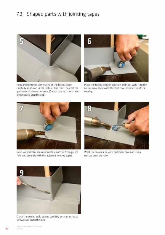
Sikadur-Combiflex® TF MANUALWelding76
7.3 Shaped parts with jointing tapes
Heat and form the corner area of the fitting piece carefully as shown in the picture. The form must fit the geometry of the corner area. (Do not use too much heat and proceed step by step).
Next, weld all the seam connections of the fitting piece fully and securely with the adjacent jointing tapes.
Check the cooled weld seams carefully with a slot-head screwdriver on both sides.
Place the fitting piece in position and spot weld it to the corner area. Then weld the first few centimetres of the overlap.
Weld the corner area with particular care and use a narrow pressure roller.
5
7
9
6
8
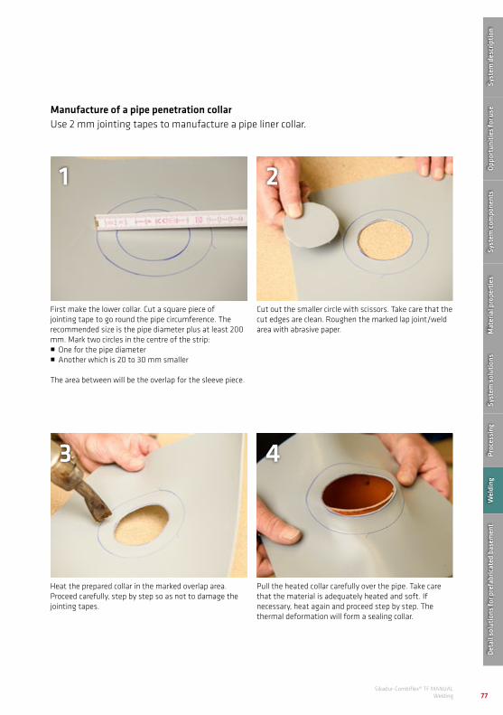
77Sikadur-Combiflex® TF MANUAL
Welding
Manufacture of a pipe penetration collarUse 2 mm jointing tapes to manufacture a pipe liner collar.
First make the lower collar. Cut a square piece of jointing tape to go round the pipe circumference. The recommended size is the pipe diameter plus at least 200 mm. Mark two circles in the centre of the strip:• One for the pipe diameter• Another which is 20 to 30 mm smaller
The area between will be the overlap for the sleeve piece.
Heat the prepared collar in the marked overlap area. Proceed carefully, step by step so as not to damage the jointing tapes.
Cut out the smaller circle with scissors. Take care that the cut edges are clean. Roughen the marked lap joint/weld area with abrasive paper.
Pull the heated collar carefully over the pipe. Take care that the material is adequately heated and soft. If necessary, heat again and proceed step by step. The thermal deformation will form a sealing collar.
1
3
2
4Sy
stem
des
crip
tion
Oppo
rtun
ities
for u
seSy
stem
com
pone
nts
Mat
eria
l pro
pert
ies
Syst
em s
olut
ions
Proc
essi
ngW
eldi
ngDe
tail
solu
tions
for p
refa
bric
ated
bas
emen
t

Sikadur-Combiflex® TF MANUALWelding78
7.3 Shaped parts with jointing tapes
Draw the collar right down to the concrete substrate until it is flush with the base.
Roughen the overlap / weld areas with sandpaper.
In the next step add the sleeve piece. Cut a rectangular piece of jointing tape to go round the pipe circumference. Recommended size: Circumference of the pipe plus approx. 40 mm, width 150 mm.
Heat the sleeve piece at the lower end to form a collar.
5
7
6
8
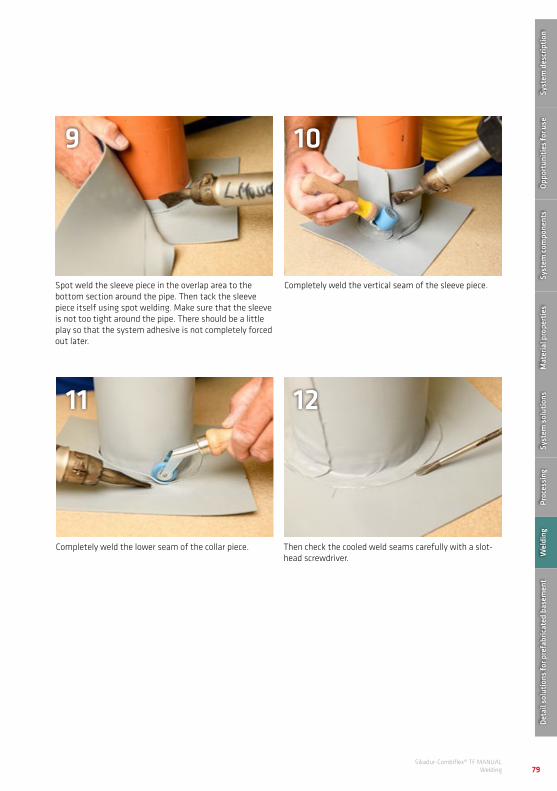
79Sikadur-Combiflex® TF MANUAL
Welding
Completely weld the vertical seam of the sleeve piece.
Then check the cooled weld seams carefully with a slot-head screwdriver.
Spot weld the sleeve piece in the overlap area to the bottom section around the pipe. Then tack the sleeve piece itself using spot welding. Make sure that the sleeve is not too tight around the pipe. There should be a little play so that the system adhesive is not completely forced out later.
Completely weld the lower seam of the collar piece.
10
12
9
11
Syst
em d
escr
iptio
nOp
port
uniti
es fo
r use
Syst
em co
mpo
nent
sM
ater
ial p
rope
rtie
sSy
stem
sol
utio
nsPr
oces
sing
Wel
ding
Deta
il so
lutio
ns fo
r pre
fabr
icat
ed b
asem
ent

Sikadur-Combiflex® TF MANUALWelding80
7.4 Welded connections with waterbar profiles
Sikadur-Combiflex® TF Waterbar profiles cannot be connected by overlap welding due to their geometry (locking anchor and expansion bulb). Waterbar profiles can only be butt welded. Use and application is regulated in accordance with DIN 18197 "Sealing of joints in concrete with waterstops". According to the specifications of this standard, butt joints between two waterbars (without change of direction) can only be produced on the building site by specialist personnel with an appropriate welding device.
The following tools and equipment are required for the professional production of butt welds:• Metal angle for cutting the correct angle• Sharp cutting knife (Quarter moon knife, recommended)• Welding device with holder and Teflon- coated welding mirror, set to 240 °C• Matching clamping rails (depending on
profile)• Meter rule or measuring tool• Pen or pencil• Pliers

81Sikadur-Combiflex® TF MANUAL
Welding
The butt weld is produced as follows:
Cut profiles to length and to the correct angle. Add approx. 5 mm to each end to accommodate melting loss.
Use only appropriate welding devices with Teflon-coated welding mirrors. Set the welding mirror of the welding device to 240°C. Let welding mirror to heat up fully before welding.
1 2
Always use accurately fitting clamping rails for the respective profile to clamp the waterbar profile ends into the welding device holder.
Ensure a matching protrusion of the waterbar. The ends must meet evenly and absolutely parallel.
3 4
Retract the welding mirror and melt the profile ends evenly, applying pressure. Melting takes place in two phases.
The first phase is the alignment phase: To this end, apply 10 kg pressure to the two waterbar ends for approx. 5-10 seconds.
5 6Sy
stem
des
crip
tion
Oppo
rtun
ities
for u
seSy
stem
com
pone
nts
Mat
eria
l pro
pert
ies
Syst
em s
olut
ions
Proc
essi
ngW
eldi
ngDe
tail
solu
tions
for p
refa
bric
ated
bas
emen
t

Sikadur-Combiflex® TF MANUALWelding82
The second phase is the melting phase: Reduce the pressure to ca. 5 kg and apply melting heat for approx. 20-30 seconds.
After it has cooled completely, the waterbar can be removed from the welding machine. Finally, carefully pinch off the welding bead all round with a pair of pliers.
As soon as the interfaces have melted, withdraw the welding mirror and push the molten profile ends together (in line) immediately (clamp and lock). Allow the joint to cool down under pressure for at least 10 minutes without tension.
The finished butt joint. If you want, check the seam with a spark tester.
7
9
8
10
7.4 Welded connections with waterbar profiles

83Sikadur-Combiflex® TF MANUAL
Welding
7.5 Shaped parts with waterbar profiles
According to the specifications of DIN 18197 "Sealing of joints in concrete with waterstops", shaped parts for waterbar profiles may not be produced on site. All shaped parts must be manufactured exclusively in the factory according to the geometric requirements of the project. To this end, CAD-production drawings must be produced for shaped parts and waterbar
systems. After approval of the production drawings by the building site, the shaped parts are manufactured in the waterbar workshop according to the dimensional and geometric specifications. The individual shaped parts are then delivered to the building site where they are incorporated into a closed system using butt joints.
Example of a shaped part sketch for production in waterbar manufacturing
Syst
em d
escr
iptio
nOp
port
uniti
es fo
r use
Syst
em co
mpo
nent
sM
ater
ial p
rope
rtie
sSy
stem
sol
utio
nsPr
oces
sing
Wel
ding
Deta
il so
lutio
ns fo
r pre
fabr
icat
ed b
asem
ent

Sikadur-Combiflex® TF MANUALWelding84
Shaped parts from DFT waterbar profiles
7.5 Shaped parts with waterbar profiles

85Sikadur-Combiflex® TF MANUAL
Welding
Syst
em d
escr
iptio
nOp
port
uniti
es fo
r use
Syst
em co
mpo
nent
sM
ater
ial p
rope
rtie
sSy
stem
sol
utio
nsPr
oces
sing
Wel
ding
Deta
il so
lutio
ns fo
r pre
fabr
icat
ed b
asem
ent

Sikadur-Combiflex® TF manualSystem detail solutions for prefabricated basement86
8 SYSTEM DETAIL SOLUTIONS FOR PREFABRICATED BASE-MENT
Terraced house without separated base plate and without toe
Terraced house with separated base plate and without toe
Profile 250/2 Profile 200/1
DF T 330/3
Profile 250/2 Profile 200/1
Profile DFT 330/3
The waterproofing of precast basements is one of the most frequent uses of the Sikadur-Combiflex® TF system. The following system diagrams show a typical method for this kind of use.

87Sikadur-Combiflex® TF MANUAL
System detail solutions for prefabricated basement
Transition base/wall without toe
cover layer 1–2 mm
sealing strip 200/1
base layer 1–2 mm
10cm
20cm
Profile 200/1
Terraced house without separated base plate and with toe
Profile 250/2 Profile 200/1
Terraced house with separated base plate and with toe
DF T 330/3
Profile 250/2 Profile 200/1 Profile DFT 330/3
Syst
em d
escr
iptio
nOp
port
uniti
es fo
r use
Syst
em co
mpo
nent
sM
ater
ial p
rope
rtie
sSy
stem
sol
utio
nsPr
oces
sing
Wel
ding
Deta
il so
lutio
ns fo
r pre
fabr
icat
ed b
asem
ent

Sikadur-Combiflex® TF manualSystem detail solutions for prefabricated basement88
Butt joint wall/wall
sealing strip 150/1
base layer 1–2 mm
cover layer 1–2 mm
7,5c
m
15cm
Profile 150/1
Transition base/wall with toe
10 cm
sealing strip 200/1
base layer 1–2 mm
cover layer 1–2 mm
10cm
Profile 200/1
Butt joint wall/wall – outside corner
sealing strip 150/1
base layer 1–2 mm
cover layer 1–2 mm
ca. 6
cm
15cm
Profile 150/1

89Sikadur-Combiflex® TF MANUAL
System detail solutions for prefabricated basement
Butt joint wall/wall – inside corner
7,5cm
sealing strip 150/1
base layer 1–2 mm
cover layer 1–2 mm
7,5c
m
Profile 150/1
Waterproofing of transport or clamping sleeves
top view:
10cm
10cm
sealing strip 200/1
base layer 1–2 mm
cover layer 1–2 mm
10cm
Profile 100/1
Syst
em d
escr
iptio
nOp
port
uniti
es fo
r use
Syst
em co
mpo
nent
sM
ater
ial p
rope
rtie
sSy
stem
sol
utio
nsPr
oces
sing
Wel
ding
Deta
il so
lutio
ns fo
r pre
fabr
icat
ed b
asem
ent

90Sikadur-Combiflex® TF MANUALImportant notices
9 IMPORTANT NOTICES
Restrictions• The products of the Sikadur-Combiflex®
TF system may only be used as specified.• The respectively latest and relevant
product data sheets (PDB) and material safety data sheets (MSDB) apply.
• The Sikadur-Combiflex® TF system may only be installed by trained and qualified specialist personnel. Corresponding Tested training is provided in our training centre. Please note our current training schedule and/or contact your authorised dealer.
• If subject to pressurised water, the jointing tape must be supported in the expansion joint with a suitable joint filler (positive water pressure) or a drag sheet construction (negative water pressure).
• The Sikadur-Combiflex® TF jointing tapes must be protected against mechanical damage.
• All seam connections must be welded.• Protect the system from heat.
DocumentationTo guarantee the correction use of all components of the Sikadur-Combiflex® TF system it is necessary to read the separately available documents of the individual system components as amended:
• PDS (Product Data Sheet)• MSDS (Material Safety Data Sheet)
Health and safety gearHandling or processing epoxy resin products can cause chemical irritation to eyes, skin, nose and throat.
• Therefore, always wear appropriate eye protection when handling and mixing these products.
• Safety shoes, protective gloves approved for epoxy resin and other adequate skin protection products should always be worn.
• After handling these products and before consuming food, always wash your hands with suitable soap and follow the skin protection plan.

91Sikadur-Combiflex® TF MANUAL
Important notices
In addition to protective clothing and equipment, it is also recommended to apply a skin protection cream. If you get epoxy resin or a hardener component onto your clothing, remove the clothing immediately. The friction of the resin-saturated tissue on the skin can lead to severe chemical burns. Wash your exposed skin several times in the course of a working day or immediately if any substances get on the skin. Avoid solvents because they contribute to the material penetrating the skin. Solvents can be aggressive and harmful for the skin. Avoid all contact with skin and keep clothing, tools and equipment correspondingly clean.
Note:When fully cross-linked and fully reacted, epoxies pose no danger. Only the unmixed raw components and/or not fully reacted substances have a sensitising effect.If skin contact occurs despite the safety precautions, rinse immediately with clean, warm water. Use soap to clean skin thoroughly.
You can find more information onthe safety data sheet of the respective product.
Legal notesThe information and in particular the recommendations for the application and end use of Sika products are given in good faith based on Sika's current knowledge and experience with the products when properly stored, handled and applied under normal conditions in accordance with Sika's recommendations. In practice, the differences in materials, substrates and actual site conditions are so great that no guarantee of marketability or suitability for a particular purpose can be given. Likewise, no liability can be derived from a legal relationship either on the basis of this information or the written recommendations or other consultation offers. The user of the product is responsible for checking the suitability of the products for the intended application purpose. Sika reserves the right to change the characteristics of the product. The commercial property rights of third party must be taken into consideration. Our up-to-date terms of sale and delivery apply for all orders. Users must always refer to the latest editions of the local product data sheets for the product concerned, which are available on request.

Sikadur-Combiflex® TF MANUALSystem solutions92
Notes

93Sikadur-Combiflex® TF MANUAL
System solutions

WAT
ERPR
OO
FIN
G/SI
KADU
R C
OM
BIFL
EX T
F M
ETH
OD
STAT
EMEN
T A
5 VE
R 1
- 07
2021
UK
JU
LY 2
021
The information, and, in particular, the recommendations relating to the application and end use of Sika® products, are given in good faith based on Sika’s current knowledge and experience of the products when properly stored, handled and applied under normal conditions. In practice, the differences in materials, substrates and actual site conditions are such that no warranty in respect of merchantability or of fitness for a particular purpose, nor any liability arising out of any legal relationship whatsoever, can be inferred either from this information, or from any written recommendations, or from any other advice offered. The proprietary rights of third parties must be observed. Please refer to our homepage www.sika.co.uk for our current standard terms & conditions applicable to all orders. Users should always refer to the most recent issue of the Product Data Sheet for the product concerned, copies of which will be supplied on request.
SIKA FULL RANGE SOLUTIONS FOR CONSTRUCTION:
LIQUID APPLIED ROOFING
SINGLE PLY ROOFING CONCRETE CONCRETE REPAIR BUILDING FINISHINGSTRUCTURAL STRENGTHENING
JOINT SEALING FLOORINGFAÇADES INDUSTRY DISTRIBUTION
BITUMINOUS ROOFING
WATERPROOFING
WHO WE ARESika Limited and Sika Ireland Limited are part of the global Sika Group, specialising in the manufacture and supply of chemical based products. Sika has a leading position in the development and production of systems and products for bonding, sealing, damping, reinforcing, and protecting in the building sector and the motor vehicle industry. Sika has subsidiaries in 100 countries around the world and manufactures in over 300 factories. With more than 25,000 employees Sika generates annual sales of CHF 7.9 billion (£6.14 bn). We are also committed to providing quality, service, safety and environmental care.
In the UK and Ireland, we provide market-leading solutions for concrete, waterproofing, roofing, flooring, refurbishment, sealing & bonding, and industry, and have manufacturing sites in Welwyn Garden City, Preston, Leeds, Wishaw and Dublin with more than 920 employees and a turnover of more than £290 million.
SIKA LIMITEDHead OfficeWatchmeadWelwyn Garden CityHertfordshire, AL7 1BQUnited Kingdom
ContactPhone +44 1 707 394444Fax +44 1 707 329129E-Mail [email protected] @SikaLimited