MeteringCode V02 03112014 Corrected - Abuja Electricity
128
NERC Nigeria Metering Code Version 02
Transcript of MeteringCode V02 03112014 Corrected - Abuja Electricity

NERC
Nigeria Metering Code
Version 02

Metering Code – Version 01
Table of Contents Page
INTRODUCTION ...................................................................................................................................... 3
METERING CODE ................................................................................................................................... 4
PART 1: GENERAL CONDITIONS ....................................................................................................... 12
PART 2: GRID METERING CODE ........................................................................................................ 23
PART 3: DISTRIBUTION METERING CODE ....................................................................................... 42
METERING CODE – APPENDICES...................................................................................................... 57

Metering Code – Version 01
INTRODUCTION
The current code– “Metering Code Version02” – corresponds to the review of Version 01 by the Metering Code Review Panel (MCRP), whose members are listed in Appendix G, in furtherance of its functions to keep the Metering Code and its working under review. The MCRP has developed a draft of the Metering Code, taking into account the comments received from stakeholders to the earlier version.
The following chapters present the amended complete version of the code “Metering Code Version 02.”
Metering Code – Version 01
4 of 128
METERING CODE
(Version 02)

Metering Code – Version 01
5 of 128
METERING CODE INDEX
INTRODUCTION ...................................................................................................................................... 3
METERING CODE ................................................................................................................................... 4
PART 1: GENERAL CONDITIONS ....................................................................................................... 12
1. ................................................................................................................ SECTION: BACKGROUND
12
1.1. Title .................................................................................................................................. 12
1.2. New Arrangements for the Nigerian Electricity Sector .................................................... 12
1.3. The Metering Code .......................................................................................................... 12
2. ................................................................................. SECTION: INTERPRETATION AND DEFINITIONS
13
2.1. Interpretation .................................................................................................................... 13
2.1.1. In this metering code (including the appendices), unless the context otherwise specifies or requires: .................................................................................................................................... 13
2.2. Definitions ........................................................................................................................ 14
2.2.1. Any capitalized word or expression defined in the Electric Power Sector Reform Act, 2005, Or The Market Rules and that is not defined otherwise in this Metering Code shall have, unless the contrary intention appears, the same meaning and interpretation when used in this Metering Code, including its appendices. ..................................................................................... 14
2.2.2. When applying the provisions contained in this Metering Code, and unless otherwise specified or the subject matter or context otherwise requires: ..................................................... 14
3. ................................................................................... SECTION: REVIEW PROCESS AND DISPUTES
20
3.1. Disputes ........................................................................................................................... 20
3.1.1. Any dispute relating to meters or metering equipment, which would affect the settlement and/or any payment to be made or received, shall be dealt with in accordance with the relevant disputes procedure. ...................................................................................................................... 20
3.1.2. Any dispute in relation to the following matters: .............................................................. 20
3.2. Metering CODE REVIEW PANEL ................................................................................... 20
3.3. Unforeseen Circumstances ............................................................................................. 22
3.4. Illegality and Partial InvaliDIty .......................................................................................... 22
PART 2: GRID METERING CODE ........................................................................................................ 23
1. ................................................................................................................ OBJECTIVES AND SCOPE
23
1.1. Objective .......................................................................................................................... 23
1.2. Scope ............................................................................................................................... 23
1.3. Derogations ...................................................................................................................... 23
2. ............................................................................................. SECTION: METERING REQUIREMENTS
26
2.1. Type of Connection Points ............................................................................................... 26
Metering Code – Version 01
6 of 128
2.2. Location of Main and Check Metering systems ............................................................... 26
2.3. Applicable Standards ....................................................................................................... 28
2.4. Characteristics of the Metering System ........................................................................... 29
2.5. Accuracy of Metering ....................................................................................................... 31
3. .................................................................... SECTION: OWNERSHIP AND ASSOCIATED OBLIGATIONS
35
3.1. Ownership ........................................................................................................................ 35
3.2. Proper Order .................................................................................................................... 36
3.3. Metering Information Register ......................................................................................... 36
4. ................................. SECTION: CERTIFICATION, CALIBRATION AND TESTING OF METERING SYSTEM
37
4.1. Certification ...................................................................................................................... 37
4.2. Initial Calibration .............................................................................................................. 37
4.3. Commissioning Tests ...................................................................................................... 38
4.4. Periodic Tests .................................................................................................................. 38
4.5. Other Periodic Tests ........................................................................................................ 39
4.6. Test Failure ...................................................................................................................... 39
5. ......................................................................................... SECTION: SECURITY AND DATA ACCESS
40
5.1. Sealing: ............................................................................................................................ 40
5.2. Access to Metering Data .................................................................................................. 40
PART 3: DISTRIBUTION METERING CODE ....................................................................................... 42
1. ............................................................................................................... SECTION: INTRODUCTION
42
1.1. Purpose and Scope ......................................................................................................... 42
1.2. Derogations ...................................................................................................................... 43
2. ................................................................................................................. SECTION: OBLIGATIONS
45
2.1. Installation and Replacement of Metering Equipment ..................................................... 45
2.2. Standard Metering SyStems ............................................................................................ 46
2.3. Alternatives to Standard Metering Systems .................................................................... 47
2.4. Technical requirements and accuracy of Meters ............................................................. 47
.............................................................................................................................................. SECTION: CERTIFICATION AND TESTS ...................................................................................................... 48
3.1. Certification of New Metering Installations ...................................................................... 48
3.2. Certification of existing installations ................................................................................. 50
3.3. Re-certification ................................................................................................................. 50
3.4. Inspection and Periodic Tests .......................................................................................... 50
3.5. Faulty Metering Equipment .............................................................................................. 51

Metering Code – Version 01
7 of 128
4. .................................................................................................... SECTION: ACCESS AND SECURIY
53
4.1. access to Metering Systems ............................................................................................ 53
4.2. Security of Metering Systems .......................................................................................... 53
5. ....................................................................... SECTION: METER READING AND DATA MANAGEMENT
54
5.1. Meter Reading ................................................................................................................. 54
5.2. Remote Metering Equipment ........................................................................................... 54
5.3. Data Management ........................................................................................................... 54
5.4. Data Registration ............................................................................................................. 55
5.5. Data Validation and Loss Adjustment Factors ................................................................. 55
.............................................................................................................................................. INHERENT POWERS OF THE COMMISSION ................................................................................................ 56
Chairman/CEO .............................................................................................................................. 56
METERING CODE – APPENDICES ...................................................................................................... 57
1. ........................................................................................... APPENDIX A – CERTIFICATION TESTS
58
1.1. General ............................................................................................................................ 58
1.2. Measurement transformers .............................................................................................. 58
1.3. meters .............................................................................................................................. 60
2. ......................................................................................... APPENDIX B – COMMISSIONING TESTS
63
2.1. General ............................................................................................................................ 63
2.2. Measurement Transformers ............................................................................................ 63
2.3. Measurement transformers leads and burdens ............................................................... 63
2.4. Metering ........................................................................................................................... 63
3. ........................................................................................ APPENDIX C – SEALING PROCEDURES
65
3.1. Sealing Procedure at the Laboratory ............................................................................... 65
3.2. Sealing Procedure at Point of Installation ........................................................................ 65
3.3. Sealing Procedure at point of Maintenance, recalibration, inspecting, site testing of meters etc ..................................................................................................................................... 65
3.4. Seals Specifications ......................................................................................................... 66
3.5. Sealing Points .................................................................................................................. 66
4.1. GENERAL ........................................................................................................................... 67
4.1.1. 67
4.1.2. 67
4.1.3. ATTRIBUTES OF COMMUNICATION MEDIA ................................................................... 67
4.2. CERTIFICATION AUTHORITY ............................................................................................. 68
4.3. TECHNICAL SPECIFICATIONS FOR ELECTRO-MECHANICAL METERS ....................... 68
Metering Code – Version 01
8 of 128
4.3.1. SINGLE PHASE ELECTRO-MECHANICAL METER ......................................................... 68
4.3.2. POLY-PHASE ELECTRO-MECHANICAL METER ............................................................ 69
4.4. TECHNICAL SPECIFICATIONS FOR STATIC/ELECTRONIC METERS ............................ 71
4.4.1. GENERAL CONSTRUCTION AND COMPONENT SPECIFICATIONS FOR STATIC ENERGY METERS ....................................................................................................................... 71
4.4.2. OTHER GENERAL COMPONENT SPECIFICATIONS......................................................... 71
4.4.3. GENERAL TAMPER AND ANTI-FRAUD DETECTION/EVIDENCE FEATURES ............. 73
4.4.4. GENERAL REQUIREMENTS ............................................................................................. 74
.............................................................................................................................................. DEFAULT DISPLAY .................................................................................................................................. 78
.............................................................................................................................................. ON DEMAND DISPLAY ............................................................................................................................. 78
4.4.8.1. THE LV CT OPERATED M.D METER SHALL RECORD ACTIVE ENERGY IN FORWARD DIRECTION EVEN IF ONE OR MORE CTS ARE REVERSED. FOR CONSUMER METERING APPLICATION, CURRENT VECTOR DIRECTION SHOULD ALWAYS BE CONSIDERED AS POSITIVE (IMPORT) FOR THE COMPUTATION OF THREE PHASE ACTIVE ENERGY, WHICH SHALL BE ADDED TO THE MAIN ACTIVE ENERGY (IMPORT) REGISTER. ................................... 87
4.4.8.2. THE M.D METER SHALL RECORD APPARENT ENERGY IN FORWARD DIRECTION EVEN IF ONE OR MORE CTS ARE REVERSED. KVA SHALL BE COMPUTED AS: ....................... 88
KVA = √ (KW2 + KVAR2 )FOR LAGGING REACTIVE ENERGY AND KVA = KW FOR LEADING REACTIVE ENERGY. ............................................................................................................................ 88
4.4.9.1. THE HV CT OPERATED M.D METER SHALL RECORD ACTIVE ENERGY IN FORWARD DIRECTION EVEN IF ONE OR MORE CTS ARE REVERSED. FOR CONSUMER METERING APPLICATION, CURRENT VECTOR DIRECTION SHOULD ALWAYS BE CONSIDERED AS POSITIVE (IMPORT) FOR THE COMPUTATION OF THREE PHASE ACTIVE ENERGY, WHICH SHALL BE ADDED TO THE MAIN ACTIVE ENERGY (IMPORT) REGISTER. ................................... 91
4.4.9.2. THE M.D METER SHALL RECORD APPARENT ENERGY IN FORWARD DIRECTION EVEN IF ONE OR MORE CTS ARE REVERSED. KVA SHALL BE COMPUTED AS ........................ 91
KVA = √ (KW2 + KVAR2 ) FOR LAGGING REACTIVE ENERGY AND KVA = KW FOR LEADING REACTIVE ENERGY. ............................................................................................................................ 91
4.4.10. STATIC GRID ENERGY METER (33KV AND ABOVE) ...................................................... 91
S/N .......................................................................................................................................................... 91
FUNCTION/FEATURE ........................................................................................................................... 91
TECHNICAL REQUIREMENTS ............................................................................................................. 91
1 .............................................................................................................................................................. 91
VOLTAGE .............................................................................................................................................. 91
3X-/110/63.5V ......................................................................................................................................... 91
2 .............................................................................................................................................................. 91
CURRENT .............................................................................................................................................. 91
3X-/1A ..................................................................................................................................................... 91
3 .............................................................................................................................................................. 91
FREQUENCY ......................................................................................................................................... 91
50HZ ±2% ............................................................................................................................................... 91

Metering Code – Version 01
9 of 128
4 .............................................................................................................................................................. 91
SYSTEM ................................................................................................................................................. 91
3PH3W/3PH4W ...................................................................................................................................... 91
5 .............................................................................................................................................................. 91
SECONDARY VOLTAGE VARIATION ................................................................................................. 91
(85 – 120)V/(50 – 70)V ........................................................................................................................... 91
6 .............................................................................................................................................................. 91
INTERNAL BATTERY ........................................................................................................................... 91
LITHIUM CR2025 – 1HF OR AN EQUIVALENT GIVING A TOTAL STAND-BY LIFE OF 10 YEARS (MINIMUM) ............................................................................................................................................. 91
7 .............................................................................................................................................................. 91
AUXILIARY BATTERY .......................................................................................................................... 91
SHALL BE 12 D.C. SUPPLY FOR DOWNLOADING STORED DATA. ............................................... 91
8 .............................................................................................................................................................. 91
ACCURACY CLASS .............................................................................................................................. 91
0.5S FOR 33KV, 0.2S FOR 132 AND 330KV........................................................................................ 91
9 .............................................................................................................................................................. 92
OPERATING TEMP. RANGE ................................................................................................................ 92
UP TO 60OC ........................................................................................................................................... 92
10 ............................................................................................................................................................ 92
STORAGE TEMP. RANGE .................................................................................................................... 92
UP TO 70OC ........................................................................................................................................... 92
11 ............................................................................................................................................................ 92
RELATIVE HUMIDITY ........................................................................................................................... 92
UP TO 96% AT 45OC NON-CONDENSING .......................................................................................... 92
12 ............................................................................................................................................................ 92
BURDEN ................................................................................................................................................ 92
2VA/PHASE IN VOLTAGE CIRCUIT AND1VA/PHASE IN CURRENT CIRCUIT ................................ 92
13 ............................................................................................................................................................ 92
CASING MATERIAL .............................................................................................................................. 92
THE CASING SHALL BE FOR WALL MOUNTING AND FIRE RETARDANT TYPE OF BAKELITE OR POLYCARBONATE ........................................................................................................................ 92
14 ............................................................................................................................................................ 92
SCREWS ................................................................................................................................................ 92
CURRENT TERMINALS ........................................................................................................................ 92
CABLE SIZE/TYPE ................................................................................................................................ 92
VOLTAGE TERMINALS ........................................................................................................................ 92
CABLE SIZE/TYPE ................................................................................................................................ 92
AUXILIARY TERMINAL ......................................................................................................................... 92
Metering Code – Version 01
10 of 128
CABLE SIZE/TYPE ................................................................................................................................ 92
ALL SCREWS SHALL BE STAINLESS STEEL OR NICKEL PLATED BRASS ................................. 92
2 PER TERMINAL (6MM) ...................................................................................................................... 92
4MMSQ/MULTI STRAND ...................................................................................................................... 92
1 PER TERMINAL (4MM) ...................................................................................................................... 92
2.5MMSQ/SINGLE CORE ...................................................................................................................... 92
3MM ........................................................................................................................................................ 92
1.5MMSQ/SINGLE CORE ...................................................................................................................... 92
15 ............................................................................................................................................................ 92
INSULATION .......................................................................................................................................... 92
A) 2.0KV FOR 1MIN FOR CURRENT CIRCUIT ................................................................................ 92
B) 2.0KV FOR 1MIN FOR VOLTAGE CIRCUIT ................................................................................ 92
C) 4.0KV FOR 1 MIN FOR CURRENT, VOLTAGE, ALL RELAY CONTACTS PLUS AUXILIARY INPUTS PLUS RS485 PORT TOGETHER ............................................................................................ 92
D) 4.0KV FOR 1 MIN BETWEEN ALL RELAY CONTACTS AND THE AUXILIARY INPUT PLUS COMMUNICATION PORT (RS485) ....................................................................................................... 92
E) 4.0KV FOR 1MIN BETWEEN ONE SET OF RELAY CONTACTS AND THE OTHER RELAY. . 92
16 ............................................................................................................................................................ 93
NAME PLATE ........................................................................................................................................ 93
17 ............................................................................................................................................................ 94
MEASURED QUANTITY ........................................................................................................................ 94
A) IMPORT KWH ............................................................................................................................... 94
B) EXPORT KWH ............................................................................................................................... 94
C) IMPORT KVARH ........................................................................................................................... 94
D) EXPORT KVARH .......................................................................................................................... 94
E) MAXIMUM DEMAND IN KVA ....................................................................................................... 94
F) FOUR QUADRANT KVARH ......................................................................................................... 94
G) LOAD PROFILE (180 – 450) DAYS .............................................................................................. 94
18 ............................................................................................................................................................ 94
TARIFFICATION .................................................................................................................................... 94
A) TIME OF USE REGISTER ............................................................................................................ 94
B) MD REGISTER .............................................................................................................................. 94
C) PROGRAMMABLE INTEGRATION PERIOD .............................................................................. 94
D) SWITCHING TIMES ...................................................................................................................... 94
E) SEASONS TIME ............................................................................................................................ 94
F) BILLING DATES ........................................................................................................................... 94
G) END OF BILLING DATES ............................................................................................................. 94
19 ............................................................................................................................................................ 94
DISPLAY ................................................................................................................................................ 94
Metering Code – Version 01
11 of 128
THE DISPLAY SHALL BE CAPABLE OF DISPLAYING DEFAULT, CUSTOMER AND UTILITY MODES ................................................................................................................................................... 94
20 ............................................................................................................................................................ 94
EVENTS MONITORING ......................................................................................................................... 94
THE METER SHALL BE ABLE TO MONITOR THE FOLLOWING EVENTS AMONG OTHERS: ...... 94
A) BATTERY FAILURE ..................................................................................................................... 94
B) BATTERY ELAPSE WARNING .................................................................................................... 94
C) REVERSE RUN WARNING .......................................................................................................... 94
D) OVER CURRENT .......................................................................................................................... 94
E) OVER VOLTAGE .......................................................................................................................... 94
F) PHASE FAILURE .......................................................................................................................... 94
G) POWER FACTOR ......................................................................................................................... 94
H) DEMAND ....................................................................................................................................... 94
I) METER COMMUNICATION EVENT ............................................................................................. 94
J) TIME AND DATE OF EVENTS ETC. ............................................................................................ 94
21 ............................................................................................................................................................ 94
COMMUNICATION ................................................................................................................................ 94
A) RS485 TO BE FITTED .................................................................................................................. 94
B) OPTO PORT: ELECTRONIC, BI-DIRECTIONAL ........................................................................ 94
C) MODEMS SUCH AS MOBILE TELEPHONY, RADIO FREQUENCY, FIXED LINE, SATELLITE, OR POWER LINE COMMUNICATIONS TECHNOLOGY. .................................................................... 94
D) PROTOCOL: IEC 62056-21DLMS/COSEM ................................................................................. 94
22 ............................................................................................................................................................ 94
SAFETY CLASS .................................................................................................................................... 94
CATEGORY – IEC61010, IEC61011 CLASS II ..................................................................................... 94
23 ............................................................................................................................................................ 95
REAL TIME CLOCK .............................................................................................................................. 95
A) TYPE: CAPABLE OF SYNCHRONIZING TO A.C SUPPLY OR TO A CRYSTAL OSCILLATOR95
B) ACCURACY: BETTER THAN 0.5 OF A SECOND PER DAY AT 50OC ...................................... 95
4.17. LT MD METERING PANELS .............................................................................................. 121
5. ........................ APPENDIX E -GMC METERING CHARACTERISTICS: CLASSIFICATION OF
CONNECTION POINTS AND LOCATION OF METERING SYSTEMS .......................................... 124
5.1 General................................................................................................................................120
6 APPENDIX F. Meter Installations..................................................................................................122
6.1 Installation Standards...........................................................................................................122
6.2 Installation Accessories.......................................................................................................122
7 APPENDIX G. List of Meterig Code Panel Members 129

Metering Code – Version 01
12 of 128
METERING CODE
(VERSION 02)
PART 1: GENERAL CONDITIONS
1. SECTION: BACKGROUND
1.1. TITLE
1.1.1. This Code shall be called the Metering Code (otherwise known as “MC”) for the Nigerian Electricity Supply Industry.
1.2. NEW ARRANGEMENTS FOR THE NIGERIAN ELECTRICITY SECTOR
1.2.1. The Electric Power Sector Reform Act, 2005 (henceforth referred to as the Act) gave legal backing to the unbundling of the Nigeria Power Sector. The Act stipulates the functional unbundling of the generation, transmission and distribution sectors.
1.2.2. To ensure financial viability of the electricity industry after the unbundling stated in 1.2.1, modern accurate meters systems with reliable communication facilities shall be deployed across the industry production and supply chain to measure and record energy production and utilization.
1.3. THE METERING CODE
1.3.1. This metering code (MC) is divided in three different parts:
(a) The first Part, defines the General Conditions, which applies to the whole Code.
(b) The second Part, Grid Metering Code (GMC) sets out or refers to the requirements for the metering of the Participant’s Connection Points on the Transmission or Distribution Network. It caters for the Commercial Metering System. The Grid Metering Code is required to cover the interchange of Energy and Power:
(i) entering or exiting from the Transmission Network
(ii) entering or exiting from the Distribution Network, at any Participant’s Connection Point,
(c) The third Part, the Distribution Metering Code (DMC) specifies the technical and operational criteria, including the procedures to be complied with by the Distributor, in carrying out its obligation to provide metering services, for the metering of Customers of the Distribution System. The Distribution Metering Code is required to cover the interchange of Energy and Power entering or exiting the Distribution Network at any Customer’s Connection Point, provided that such Customer is not a Participant.
1.3.2. This Metering Code shall be read in conjunction with the Market Rules, the Grid Code, the Distribution Code and the Metering Market Procedures

Metering Code – Version 01
13 of 128
2. SECTION: INTERPRETATION AND DEFINITIONS
2.1. INTERPRETATION
2.1.1. In this metering code (including the appendices), unless the context otherwise specifies or requires:
(a) references to "the Metering Code" or "this Metering Code" or "this Code" are a reference to the whole of the Metering Code, including any Appendices or other documents attached to any part of this Metering Code;
(b) the Appendices shall be deemed to be part of this Metering Code;
(c) capitalised words used shall have the meanings assigned to them in the Definition Condition of the General Conditions Section;
(d) words corresponding to persons or parties shall include any individual, firm, joint venture and corporation, and all references to persons shall include their legal successors and permitted assignees;
(e) words in singular only also include the plural and vice versa where the context requires;
(f) words in the masculine shall include the feminine and vice versa;
(g) any reference to a day, month or year shall be construed as reference to a calendar day, month or year, as the case may be, and all references to specific dates shall be to the day commencing on such date at 00:00 hours;
(h) the headings are for ease of reference only and shall not be deemed part of and shall neither affect nor be used in the interpretation or construction of this Metering Code;
(i) the word “include” or “including” shall be construed without limitation;
(j) the word “shall” refers to a rule, procedure, requirement or any provision of this Metering Code that requires mandatory compliance;
(k) all references to a numbered Appendix, Section or Condition is respectively a reference to the Appendix, Section or Condition bearing that number in this Metering Code as well as the case for a numbered table or section in a Condition or Appendix
(l) references to the consent or approval of the NERC shall be references to the approval or consent of NERC in writing, which may be given subject to such conditions as may be determined by the NERC, as that consent or approval may be amended, modified, supplemented or replaced from time to time and to any proper order, instruction or requirement or decision of NERC given, made or issued under it; and
(m) reference to any law, by-law, code, regulation made under any law, directive or other document issued by NERC shall be construed to refer to such law, by-law, code, regulation made under any law, directive or other document issued by NERC as amended, modified or replaced from time to time. In particular, any reference to a licence shall be to that licence as amended, modified or replaced from time to time and to any rule, document, decision or arrangement promulgated or established under that licence.

Metering Code – Version 01
14 of 128
2.2. DEFINITIONS
2.2.1. Any capitalized word or expression defined in the Electric Power Sector Reform Act, 2005, Or The Market Rules and that is not defined otherwise in this Metering Code shall have, unless the contrary intention appears, the same meaning and interpretation when used in this Metering Code, including its appendices.
2.2.2. When applying the provisions contained in this Metering Code, and unless otherwise specified or the subject matter or context otherwise requires:
Act means the Electric Power Sector Reform Act, 2005, as amended from time to time;
Accuracy Class means an index indicating the permissible error in measurements.
Associated User means a User who does not own the assets at a Connection Point but has a contractual interest in the test results or data flowing from the Metering System
Automatic Meter Reading is a metering system capable of supporting through a separate two-way communications; a set of functionalities- remote readings, tamper information, auto connection and disconnection, prepayment, post-payment, tariff changes, and consumer information.
Calibration Tests means a series of tests and checks performed by an authorised Meter Test Station to determine that the accuracy of an existing Metering Installation is within the specifications of this MC. NERC will issue directives and procedures regarding the Calibration Tests to be performed.
Check Meter means the Meter which is used to cross-check the measurements of the Main Meter.
Check Metering means the metering and/or calculation process to determine metering data utilizing the Check Metering System
Check Metering System means the Commercial Metering System which will be used by the Market Operator, in Market Settlement process, for the purpose of checking and validating the measurements provided by the Main Metering Systems, or to replace measured data in case of failure or malfunction of the Main Metering System.
Commercial Meter means the Meter which measures the energy injected or withdrawn from the grid by a Participant, which will be used by the Market Operator in the Market Settlement process
Commercial Metering System means the system to measure and send to the Market Operator the energy injected or withdrawn from the grid by a Participant. This metering will be used for the Market Settlement process of the Market Operator.
Commission (NERC) means the Nigerian Electricity Regulatory Commission (NERC) created in the Act;
Competent Staff means a COREN registered Engineer who is a staff of an organisation recognised for membership of the Metering Code Review Panel and who has not less than ten years post qualification experience as a metering engineer familiar with the relevant standards.
Connection Agreement means an agreement between a Generator, Distribution Company or Eligible Customer and the TSP; or an agreement between a Distribution Company and a customer, as the case may be,

Metering Code – Version 01
15 of 128
which specifies the terms and conditions pertaining to the connection of the Generation Company, Distribution Company or Customer system or equipment to the Transmission or Distribution System
Connection Capacity means the maximum capacity of a connection as stated in the associated Connection Agreement
Connection Point means a site or point of connection between a Generation Station or Load Facility and the System Operator Controlled Grid or Distribution System, where a Participant connects to the system to inject or extract energy, and which will be considered its Market trading point for Market Settlement and energy commercial metering Transmission System
CT is an acronym for current transformer Current Limiter is a metering device that stores in its register a prepaid
energy value which decreases with consumption over a specific period. It cuts off supply whenever the rate of depletion is higher than replenishment for the specific period thereby requiring load adjustment.
Data Collection System means the data collection system operated by the Market Operator, for use in the Market Settlement
Data Registers means the equipment which receives, registers and stores the information received from the Meter, and serves as a link to the remote reading. Data registers could be incorporated into the Meter itself or constitute a separated piece of equipment.
Distribution Company (Disco) means a successor Distribution Company created in the restructuring of the PHCN, provided that until such companies are created it will refer to a distribution zone, or a person holding a Distribution Licence
Distribution Metering Code (DMC) means Part 3 of this Code Distribution Network means any connection of cables, service lines and
overhead lines, meters, electrical apparatus / equipment and having design voltage of 33 kV and below used to transport electric power on a Distribution System
Distribution System means any system consisting mainly of cables, service lines and overhead lines, meters, electrical apparatus / equipment having design voltage of 33 KV and below, plus related system used in the safe operation of an Electricity Network.
Distributor has the same meaning as Distribution Company Effective date means the date on which this Code comes into force Electricity Network means any connection of cables, service lines and
overhead lines, meters, electrical apparatus / equipment use to transport electric power on a Transmission or Distribution Network or both
Electromechanical Meter means a meter that carries out an analog measurement of the consumption of electricity using a rotating disc in an electromagnetic field.
Electronic Meter means a meter that carries out digital measurement of the consumption of electricity without moving parts.
Eligible Customer has the meaning assigned to the term in the Act Generation Station means a facility with one or more Generation Units. Generation Substation means a substation in the Transmission Network or
the Distribution Network, as corresponds, where Generators are connected.

Metering Code – Version 01
16 of 128
Generator means a Successor Generation Company, or an Independent Power Producer (IPP), or a Participant who is licensed to generate electricity under section 60 of the Act, including Successor Generation Companies and Independent Power Producers, and self-generation authorised by the Commission
Generator Group or Generation Group means a group of one or more similar generating units within a power plant, together with the associated plant and apparatus, whose Energy output is separately identifiable and separately metered in the Connection Point. A power plant will be considered a Generating Group unless it has separate meters for each generating unit
Generator Unit or Generation Unit means any equipment that produces Energy, including the mechanical prime mover (e.g. turbine or engine) in the case of conventional hydro or thermal plant or the equivalent principle means of converting another form of energy to electricity, in the case of unconventional generating units such as wind and solar energy. In the case of a multi-generating unit combined cycle block, a generating unit is an alternator plus its associated prime mover within the combined cycle block
GPS means Global Positioning System Grid Code means the “grid code” as defined in the Act to be prepared by
the System Operator, as amended from time to time in accordance with these Rules with the approval of the Commission
Grid Metering Code (GMC) means Part 2 of this Code High Voltage (HV) means a voltage, used for the supply of electricity,
whose lower limit of nominal root-mean-square value is greater than 33 kV IEC means International Electrotechnical Commission; Large Connection means a connection where the Connection Capacity is
greater than 4 MVA or connections with generation facilities greater than 300 kW.
Load Facility means a Distribution Company or a customer which is connected to the Transmission System
Low Voltage (LV) means a voltage, used for the supply of electricity, whose upper limit of nominal root-mean-square value is less than 1kV
Main Meter means a meter other than the Check Meter that is capable of and is used to measure the flow of active or reactive energy at a Connection Point.
Main Metering means the metering process to determine metering data utilizing the Main Metering System
Main Metering System means the Commercial Metering System which will be used by the Market Operator as a prime reference for the measurement of the active or reactive energy interchanged at a Connection Point in Market Settlement process
Market Operator means the company or entity licensed or authorized to provide market administration services and responsible for registration of Participants and commercial metering, collection and validation of meter data, the Market Settlement Process and Market Payment System
Market Rules means the Market (Settlement) Rules for the Electricity Sector of Nigeria
Metering Code – Version 01
17 of 128
Market Settlement means the process of calculating charges, due from Participants who are required to make payment, and to be paid to Participants who are due to receive payments, pursuant to the Market Rules
Medium Connection means a connection where the Connection Capacity is greater than 50 KVA and up to and including 4MVA where no generation facility greater than 50 kW exists for an LV connection and no generation facility greater than 300 kW exists for an MV connection
Medium Voltage (MV) means a voltage, used for the supply of electricity, whose nominal root-means-square value ranges between 1kV and 33 kV;
Meter means a device that measures and registers the integral active Energy or Reactive Energy over a metering interval and may include a data recorder, but shall be deemed to exclude instrument transformers
Metering Code (MC) or Code means this Code Metering Code Review Panel has the meaning indicated in Section 3 of
this Part. Metering Equipment means metering accessories like current
transformers, voltage transformers, metering protection equipment including alarms and LV electrical circuitry, associated with a Meter, but shall be deemed to exclude the Meter itself.
Metering Services Provider (MSP) means an accredited metering company, entity or specialist which is conversant with the requirements of this Code and having the technical and infrastructural capability, may be procured for the design, supply, installation, inspection, technical audit, or maintenance of metering systems.
Metering Installation, in the DMC, means a Meter or Meters and their associated Metering Equipment, if exists, which is located at a definite Customer’s location.
Meter Test Station means a certified test laboratory which has the technical and infrastructure capability to perform accuracy tests for Meters and Metering Equipment.
Meter Type means a specific and unique model of Meter of a specific manufacturer, identified by a definite trademark and type. Manufacturer’s variants of a specific Meter model or trademark, or different options of a model as voltage or current ratings, storage capacity, etc., shall be considered, for purposes of this MC as different Meter Types.
Metering Market Procedures has the meaning assigned to the term in the Market Rules
Metering System means a Meter and the associated current transformers, voltage transformers, metering protection equipment including alarms, LV electrical circuitry, associated data collectors, data transmitters related to the measurement and recording and transmitting to the Data Collection System the active energy and/or reactive energy, as the case may be.
Miniature Circuit Breaker (MCB) means an automatically operated electrical switch to protect an electrical circuit from damage caused by overload or short circuit.
Participant or Market Participant has the meaning assigned to the term in the Market Rules
Party means any person subject to the provisions of the Metering Code Point of Sale means a device for the remote purchase of electricity units to
credit to a consumer meter.

Metering Code – Version 01
18 of 128
Power Transformer means the transformers which interconnect the Transmission Network with the Distribution Networks, or the Transmission Network with the equipments or apparatus of an Eligible Customer.
Prepaid Meter means a Meter that requires the Customer to pay its consumption in advance in order to allow a connection to the network.
Routine Test means a series of tests and checks performed by an authorised Meter Test Station to determine that a new Meter or Metering Equipment complies with the provisions of this MC. Routine Tests shall be performed to each individual Meter or Metering Equipment or by sampling of a group of Meters or Metering Equipments, as prescribed by NERC directives which will include sampling techniques and Routine Tests to be performed.Routine Tests shall be performed to each individual Meter or Metering Equipment or by sampling of a group of Meters or Metering Equipments, as prescribed by NERC directives which will include sampling techniques and Routine Tests to be performedSmart Meter means a meter that can carry out self-diagnostics and is capable of supporting through a separate two-way communications a set of functionalities which include remote readings, auto connection and disconnection, prepayment, post-payment, tariff changes, fraud and error detection, consumer information exchange, and auxiliary debits or credits.
Smart Metering means a metering system consisting of smart meters, home area networks, two way communications systems, a set of functionalities and metering data management system. Also known as Advanced Metering Infrastructure (AMI).
Static Meter means the same as Electronic Meter. Station Auxiliary Transformer means the transformer at a Generation
Substation which feeds exclusively the auxiliary equipments of a Generation Unit or a Generation Group.
Step Up Transformer means the transformer that connects the stator windings of a Generation Unit with the Transmission or Distribution Network, as corresponds.
System Operator means the holder of a System Operation License, issued according to Article 66 of the Act.
System Operator Controlled Grid has the meaning assigned to the term in the Market Rules
Trader means a holder of a Trading License, issued according to Article 68 of the Act.
Transmission Network means any connection of High Voltage apparatus, equipment, lines, and stations, having design voltage of 132 KV and above used in transporting electric power on a Transmission System
Transmission Service Provider (TSP) means a holder of a Transmission License, issued according to Article 65 of the Act.
Transmission System means the System consisting of High Voltage apparatus, equipment, lines, and stations, having design voltage of 132 KV and above used in the safe operation of transmitting electrical power from the generating station bus bars up to the interconnection point with the Distribution System. This shall not include any part of the Distribution System
Type Test means a series of tests and checks performed by an authorised Meter Test Station to determine that a new Meter Type complies with the

Metering Code – Version 01
19 of 128
provisions of this MC. NERC will issue directives and procedures regarding the Type Tests to be performed to each Meter Type.
User, in Part 1 General Conditions, means any person to which this MC applies, or has any type of interest in the outcomes resulting from this MC implementation.
Urgent Metering Services means urgent unplanned work by a Distributor on a Metering System as a result of actual or potential equipment failure, actual or suspected tampering or suspected theft
VT Is an acronym for voltage transformer

Metering Code – Version 01
20 of 128
3. SECTION: REVIEW PROCESS AND DISPUTES
3.1. DISPUTES
3.1.1. Any dispute relating to meters or metering equipment, which would affect the settlement and/or any payment to be made or received, shall be dealt with in accordance with the relevant disputes procedure.
3.1.2. Any dispute in relation to the following matters:
(a) Siting of the Commercial Metering System;
(b) Technical specifications for Meters, Metering Equipment, or the Data Collection System;
(c) Sealing of Metering System;
(d) Compliance of Metering System with technical specifications of this Metering Code;
(e) Compensation values;
(f) Such other matters as the relevant Parties may agree;
shall be referred to the Metering Code Review Panel who shall act as experts and whose decision shall be final and binding on, and communicated to, the Parties concerned (giving reasons for the decision).
3.1.3. Any other dispute under this metering code shall be dealt with in accordance with the disputes procedure in the relevant connection agreement.
3.1.4. The Metering Code Review Panel can demand any information it may properly and reasonably require to settle a dispute from any party and such party shall provide the relevant information on request.
3.1.5. The Metering Code Review Panel may make recommendations to NERC on the payment of cost or/and expenses to any party in respect of any dispute referred to it.
3.2. METERING CODE REVIEW PANEL
3.2.1. A Metering Code Review Panel shall be appointed for the purposes of this Metering Code. It will comprise:
(a) Two members representing Generation Companies
(b) Two members representing Distribution Companies
(c) One member representing Meter manufacturers
(d) One member from Meter Test Stations
(e) One member from the Market Operator
(f) One member from Transmission Service Provider
(g) One member representing Traders
(h) One member from the Nigerian Electricity Regulatory Commission
3.2.2. Nominated representatives to the Metering Code Review Panel shall be competent staff of senior managerial status in the organization which they are representing.

Metering Code – Version 01
21 of 128
3.2.3. The “Metering Code Panel” shall perform the following functions:
(a) Keep the MC and its working under review.
(b) Review all suggestions for amendments to the MC which NERC, Metering Code Review Panel member or User may wish to submit to the Metering Code Review Panel Chairman for consideration by the Metering Code Review Panel from time to time.
(c) Publish recommendations as to the amendments to the MC that the Metering Code Panel feels are necessary or desirable and the reasons for these recommendations.
(d) Issue guidance in relation to the MC and its implementation, performance and interpretation upon the reasonable request of any User.
(e) Consider what changes are necessary to the MC arising out of any unforeseen circumstances or derogations approved.
(f) Resolve disputes that may arise from the implementation of this Code
3.2.4. The funding and maintenance of the Metering Code Review Panel on a budget approved by NERC, shall be the responsibility of the Market Operator, including the location of the Panel’s Secretariat.
3.2.5. The Secretary of the Metering Code Review Panel shall consult in writing with Users liable to be affected in relation to all proposed amendments to the MC and shall submit all proposed amendments to the Metering Code Review Panel for discussion prior to such amendment.
3.2.6. Members of the Metering Code Review Panel shall be appointed, from time to time, by the relevant Party or Parties concerned for a period of two years, with the possibility of renewal. As a general rule, each Party shall select its representative in a fair and transparent manner. In default of appointment by the relevant Parties, NERC shall have the right to appoint representatives from the Parties who have failed to appoint their own representatives. Members of the Metering Code Review Panel shall be required to enter into confidentiality undertakings in favour of all Parties in a form specified by NERC.
3.2.7. Decisions of the Metering Code Review Panel shall be made by voting of Panel members attending any meeting. Each Panel member shall have one vote. The Chairman, where necessary, (and unless otherwise provided) shall have a casting vote. Five (5) Panel members shall be a quorum for any meeting of the Metering Code Review Panel No less than 5 Business Days notice of a meeting of the Metering Code Review Panel is required to be given to all Panel members entitled to attend such meeting except in the case of an emergency meeting.
3.2.8. The Chairman shall be elected by the Metering Code Review Panel from among its members who shall not be a representative of NERC.
3.2.9. The Metering Code Review Panel shall operate in accordance with such other rules and procedures as are laid down by it.
3.2.10. The Market Operator shall act as Secretary of the Metering Committee for the purpose, inter alia, of giving and receiving of notices.
3.2.11. The Metering Code Review Panel decisions, except when it settles disputes, are not binding on NERC, but shall have only the nature of an opinion. Any

Metering Code – Version 01
22 of 128
decision for amendment to the MC must be approved by NERC and be published by the Secretary of the Metering Code Review Panel in a manner agreed with NERC.
3.3. UNFORESEEN CIRCUMSTANCES
3.3.1. If circumstances not envisaged in the provisions of the MC or divergent interpretations of any provisions included in the MC should arise, the Secre tary o f the Meter ing Code Rev iew Pane l shall, to the extent reasonably practicable in the circumstances, consult promptly with all affected Users in an effort to reach agreement as to what should be done. If agreement cannot be reached in the time available, the Secre tary o f the Meter ing Code Rev iew Pane l shall in good faith determine what is to be done and notify all Users affected.
3.3.2. The Secre tary o f the Meter ing Code Rev iew Pane l shall promptly refer all such unforeseen circumstances and any determination to the Metering Code Review Panel for consideration.
3.4. ILLEGALITY AND PARTIAL INVALIDITY
3.4.1. If any provision of the MC should be found to be unlawful or wholly or partially invalid for any reason, the validity of all remaining provisions of the MC shall not be affected.
3.4.2. If part of a provision of the MC is found to be unlawful or invalid but the rest of such provision would remain valid if part of the wording were deleted, the provision shall apply with such minimum modification as may be:
(a) necessary to make it valid and effective; and
(b) most closely achieves the result of the original wording but without affecting the meaning or validity of any other provision of the MC.
3.4.3. The Secre tary o f the Meter ing Code Rev iew Pane l shall prepare a proposal to correct the default referred to 3.4.1 and 3.4.2 for consideration by the Metering Code Review Panel.

Metering Code – Version 01
23 of 128
PART 2: GRID METERING CODE
1. OBJECTIVES AND SCOPE
1.1. OBJECTIVE
1.1.1. The objectives of the Grid Metering Code are to establish:
(a) The technical, design and operational procedure for the Commercial Metering System
(b) The required accuracy and calibration of the Commercial Metering System
(c) The procedures for approval, certification and testing of the Meters and Metering Equipment
(d) The standards to be met by Market and System Operators, the TSP and Users who have or plan to have access to the Transmission Network or MV Distribution Network, provided in the later case they are, or expect to be, Participants trading in the Wholesale Market.
(e) The responsibilities of the Market Operator and Users in relation to ownership and management of Metering System and provision and use of metering data.
1.2. SCOPE
1.2.1. The Grid Metering Code applies to:
(a) The Market Operator
(b) Users, which in this part of the MC (the Grid Metering Code) are:
(i) The System Operator
(ii) The TSP
(iii) Distribution Companies (Discos);
(iv) Generators directly connected to the Transmission Network;
(v) Customers with and without self-generation directly connected to the Transmission Network, whether they qualify or not as Market Participants;
(vi) Eligible Customers with and without self-generation connected to the MV Distribution Network, provided that they qualify as Participants in the Market;
(vii) Traders.
1.3. DEROGATIONS
1.3.1. If a User finds that an existing installation cannot comply with the standards contained in this GMC or cannot meet the required accuracy levels, it shall without delay report such non compliance to the Market Operator stating the reasons for non-compliance and the proposed remedy for this situation. Where the costs of modifying existing equipment to meet the GMC standards are excessive and the equipment is expected to be changed or decommissioned within one (1) year, then application can be made to the Market Operator for a derogation.

Metering Code – Version 01
24 of 128
1.3.2. Where a User has received professional technical advice that the proposed equipment or existing equipment, although not fully meeting the standards as listed in Condition 2.3, is capable of performing to the required levels of accuracy contained in Condition 2.5 then such advice and evidence of the performance of the equipment concerned, can be submitted to the Market Operator as due process for a derogation request if the User wishes.
1.3.3. Any request for derogations from any provision of the GMC by a User shall contain:
(a) the issue number and the date of the GMC provision against which the derogation applies;
(b) identification of the Meters or Metering Equipment in respect of which a derogation applies and, if relevant, the nature and extent to which the derogation applies including alternate compliance provisions;
(c) identification of the provision with which the derogation applies;
(d) the reason for the non-compliance requiring derogation;
(e) proposed remedial actions, if any ;and
(f) the date by which the derogation ends if compliance will be achieved, or by which such derogation expires.
1.3.4. On receipt of any request for derogation, the Market Operator shall promptly consider such a request provided that it considers that the grounds for the derogation are reasonable. The Market Operator shall notify the NERC of the request, together with its opinion on:
(a) Whether the derogation would, or is likely to:
(i) have a material adverse impact on the accuracy of the settlement system; or
(ii) impose unreasonable costs on the operation of the Transmission System or on an Interconnected Party’s System.
(b) Whether the derogation should be granted.
1.3.5. NERC may grant derogation as requested or grant it subject to other provision or reject the request while taking into account the opinion of the Market Operator.
1.3.6. NERC shall inform the Market Operator of its decision within 20 calendar days of receipt of the Market Operator´s notification, provided that if NERC does not answer within this timeframe, the Market Operator must consider that the opinion of the Market Operator has been accepted.
1.3.7. To the extent of any derogation granted, the User shall be relieved from its obligation to comply with the applicable provision of the GMC and shall not be liable for failure to so comply but shall comply with any alternate provisions as set forth in the derogation.
1.3.8. The Market Operator shall:
(a) keep a register of all derogations which have been granted, identifying the name of the person and User in respect of whom the derogation has been granted, the relevant provision of the GMC and the period of the derogation; and

Metering Code – Version 01
25 of 128
(b) on request from any User, provide a copy of such register of derogations to such User.
(c) Where a material change in circumstance has occurred, a review of any existing derogations, and any derogations under consideration, may be initiated by the Market Operator, NERC or an Associated User.
Metering Code – Version 01
26 of 128
2. SECTION: METERING REQUIREMENTS
2.1. TYPE OF CONNECTION POINTS
2.1.1. Commercial Metering Systems shall be installed to measure active energy and reactive energy, at each Connection Point on the Transmission or Distribution Network, which corresponds to an interface exists between two or more Participants. This will comprise both Import and Export metering when reasonably required by the Market Operator.
2.1.2. Commercial Metering Systems comprises both the Main Metering System and the Check Metering System, when the later is required.
2.1.3. For the purposes of this GMC the Connection Points shall be classified as in Appendix E as follows:
(a) Type 1: Between a Generator Unit or Generator Group with a Connection Capacity equal to or higher than 20 MW and the Transmission Network
(b) Type 2: Between the Transmission Network and a Distribution Network
(c) Type 3: Between the Transmission Network and an Eligible Consumer, with a Connection Capacity equal to or higher than [10 MW]
(d) Type 4: International Interconnections
(e) Type 5: Between two Distribution Networks of different licensees
(f) Type 6: All other Connection Points
2.1.4. Main and Check Metering Systems shall be installed as in Appendix E in all Connection Points of Type 1, 2, 3, 4 or 5. In Type 6 Connection Points only Main Metering Systems shall be installed, although an installation of a Check Metering System is advisable.
2.1.5. Check Metering can be obtained through Redundant Metering or Verification Metering.
(a) Redundant Metering: Metering Equipment, installed at the same Connection Point where the Main Meter is installed. In principle, Main and Redundant Meters measurements shall be coincident.
(b) Verification Metering: Metering Equipment, or set of Metering Equipments installed in different locations than the Main Meter, whose measurements permits the verification of the Main Meter measurement through simple calculations that eliminates the effect of the network element that could exist between them.
2.2. LOCATION OF MAIN AND CHECK METERING SYSTEMS
2.2.1. As a general rule, both Main Metering System and Check Metering System, will be located as close as practicable to the Connection Point. Where there is a material difference in location, an adjustment for losses between the location of the Metering System and the Connection Point will be calculated by the Market Operator and agreed to by the User. Such loss adjustments may include transformer and line loss compensation resulting from the distance of the Metering System to the physical location of the Connection Point.
2.2.2. Type 1 Connection Points

Metering Code – Version 01
27 of 128
(a) As far as possible, the Main Metering System at Generation Stations shall be located at the actual Connection Points:
(i) At the HV side of the Step Up Transformer of the Generator Unit for energy exported
(ii) At the HV side of the Station Auxiliary Transformer
(b) Check Metering shall be obtained either:
(i) Through a Redundant Meter, located at the same point as the Main Metering System. In this case, Provision 2.2.2 (a) shall apply, or
(ii) Through Verification Metering, with Meters located at the Connection Points of each outgoing feeder of the Generation Substation
2.2.3. Type 2 Connection Points
(a) The Main Metering System shall be located at the LV side of the Power Transformers of the substation that connects the Transmission System with the Distribution System.
(b) Check Metering shall be obtained either:
(i) Through a Redundant Meter, located at the same point as the Main Metering System. In this case, Provision 2.2.3 (a) shall apply, or
(ii) Through Verification Metering, with Meters located at each of the outgoing MV distribution feeders, or
(iii) Exceptionally, in case neither (i) or (ii) could be applied, through Verification Metering, with Meters located at the HV side of the Power Transformers of the substation that connects the Transmission System with the Distribution System.
2.2.4. Type 3 Connection Points
(a) The Main Metering System shall be located at the actual Connection Point between the Transmission System and the Eligible Customer.
(b) Check Metering shall be obtained either:
(i) Through a redundant Meter, located at the same point as the Main Metering System. In this case, Provision 2.2.4 (a) shall apply, or
(ii) Through Verification Metering, with Meters located at each incoming Transmission Line into the Substation.
2.2.5. Type 4 Connection Points
(a) The Main Metering System shall be located at the Connection Point, in the Nigerian Substation, of the line that interconnects Nigeria with any neighbouring country.
(b) Check Metering shall be obtained either:
(i) Through a Redundant Meter, located at the same point as the Main Metering System, In this case, Provision 2.2.5 (a) shall apply, or
(ii) Through Verification Metering, with Meters located in the other extreme of the interconnection line (in the neighbouring country), if the Market Operator agrees with this possibility and the

Metering Code – Version 01
28 of 128
Interconnection Agreements allows adequate interchange of the information required in a timely manner.
2.2.6. Type 5 Connection Points
(a) The Metering Systems shall be located at both ends of the line between substations of different licensees.
(b) Each licensee shall consider the Metering System at its own substation as Main Metering. Verification Metering can be obtained through the measurements in the other extreme.
2.2.7. Type 6 Connection Points
(a) The Main Metering System shall be located as close as possible to the actual Connection Point.
2.3. APPLICABLE STANDARDS
2.3.1. The accuracy of the various items of measuring equipment comprising Meters and Metering Systems shall conform to the relevant IEC standards or any equivalent Nigerian standards. The following IEC standards approved for use with this GMC are:
(a) IEC Standard 62053-22 – Alternating current static meters for active energy (classes 0.2 S and 0.5 S).
(b) IEC Standard 62053-21 - Alternating current static meters for active energy (classes 1 and 2).
(c) IEC Standard 62053-11 – Alternating current electromechanical meters for active energy (classes 0.5, 1 and 2).
(d) IEC Standard 62053-23 – Alternating current static meters for reactive energy (classes 2 and 3).
(e) IEC Standard 60044 Part 1 – Current transformers.
(f) IEC Standard 60044 Part 2 – Voltage transformers.
(g) IEC Standard 60044 Part 3 – Combined transformers.
(h) IEC Standard 62056-21 – Data exchange for meter reading – Direct local data exchange.
(i) IEC Standard 62052-11 General Requirements for meters.
2.3.2. Whenever the above mentioned IEC Standards are followed, necessary corrections or modifications shall be made for nominal system frequency, nominal system voltage, ambient temperature, humidity and other conditions prevailing in Nigeria before actual adoption of the said Standards.
2.3.3. All Meters and Metering Systems shall comply with the relevant standards. Where relevant standards change from time to time, the Market Operator will review such changes and recommend to NERC through the Metering Code Review Panel the extent to which any changes should be implemented.
2.3.4. Where a User proposes to utilize equipment that does not meet these standards, then a derogation submission must be made to the Market Operator in accordance with Chapter 1.4

Metering Code – Version 01
29 of 128
2.4. CHARACTERISTICS OF THE METERING SYSTEM
2.4.1. Measuring Transformers characteristics and installation:
(a) Measuring transformer shall be always of inductive type.
(b) Main and Check Metering shall operate from separate current transformer (CT) and voltage transformer (VT) windings.
(c) As a general rule, CT and VT windings and cables connecting such windings to Main or Check Metering shall be dedicated for such purposes and such cables and connections shall be securely sealed.
(d) Eventually, CT and VT windings and cables connecting such windings to Check Meters may be used for other purposes provided the overall accuracy requirements are met and evidence of the value of the additional burden is available for inspection by the Market Operator.
(e) Connection cables between VT and the metering equipment shall have a section enough to guarantee that the voltage drop will be always lower than 1 per 1000. The maximum burden imposed by the cables that connect the current transformers with the metering equipment shall be lower than 4 VA. In any case the section of these cables shall not be lower than 6 mm2.
(f) The Main Meter, Check Meter and additional burdens shall have separately fused VT supplies. Adequate devices shall be provided to immediately detect the absence of voltage to the metering equipment in any of the three phases
2.4.2. Meters shall be static type, and relevant standard regarding the number of wires shall apply.
2.4.3. Meters shall be capable of measuring data at least half-hourly, and record them automatically on integral or separate Data Registers. In any case, all Meters shall have a display showing the accumulated values of the measured quantities.
2.4.4. Registers of active energy shall be done in all the ways the energy could flow. This may be achieved by using one or more metering equipment as may be convenient. Registers of reactive energy shall be done in all the four quadrants reactive energy could flow. This may be achieved by using one or more metering equipments as it is convenient
2.4.5. In cases where separate Data Registers are used, each Data Register may store information from one or more Metering Equipment, provided that Redundant or Verification Meters shall have separate Data Registers from the Main Meters.
2.4.6. Data Registers shall have adequate capacity to store at least three (3) months of on site data in non volatile memories, to allow for any interruptions to the automatic Data Collection System.
2.4.7. The Meter or the Data Register, as the case may be, shall have an adequate communication channel, either through a serial port RS-232, opto-couplers according to IEC Standard 62.056-21, or any other system the Market Operator may authorize. This communication channel will permit automatic downloading, including remote interrogation and batch downloading, by the Data Collection System.
Metering Code – Version 01
30 of 128
2.4.8. For the purposes of remote interrogation of Meters or Data Registers, as the case may be, the Market Operator may use its own data communications network, or that of the System Operator. For redundancy purposes, it shall enter into, manage and monitor contracts to provide for the maintenance of all data links by which data is passed from the Meters or Data Registers, as the case may be, to the Data Collection System.
2.4.9. The Market Operator shall define the communication protocol to be used, which shall be unique and of standard type in order to reduce the costs that shall be borne by the Users. The selected communication protocol shall be approved by NERC and communicated to the involved Users at least six (6) month before remote interrogation will start.
2.4.10. To prevent unauthorised access to the data in the Meters or Data Registers a security scheme shall be incorporated for both local and remote access. Separate security levels shall be provided for the following activities:
(a) Level 1 - Password for read only of the following metering data, which shall be transferable on request during the interrogation process:
(i) Meter of Data Register ID;
(ii) Energy Metered Values;
(iii) Cumulative measured quantities;
(iv) Alarm indications; and
(v) Meter or Data Register time and date.
(b) Level 2 - Password for corrections to the time and/or date and resetting of maximum values.
(c) Level 3 - Password for programming of
(i) Displays, tariff schemes and other functions; and
(ii) The passwords for levels 1, 2 and 3.
(d) Level 4 - Password for removal of Metering Equipment cover(s) necessitating the breaking of the seals for:
(i) Calibration of the Metering Equipment;
(ii) Programming the level 3 password and the level 4 password.
In addition to the functions specified for each level it shall be feasible to undertake the functions at the preceding or lower level.
2.4.11. Time synchronization of Meters and Data Registers, as the case may be, shall be done preferably through GPS. Other synchronization systems may be used provided that they comply with the requirements regarding accuracy and security and do not distort the calculations of the energy balances. Such other methods shall be authorised by the Market Operator.
2.4.12. The Meter shall be enclosed in a cabinet or otherwise installed in a manner which shall conform to the manufacturer’s stated environmental conditions. The installation shall provide protection from moisture and dust ingress and from physical damage, including vibration. In addition, the cabinet or meter must be sealed to prevent unauthorised access.

Metering Code – Version 01
31 of 128
2.5. ACCURACY OF METERING
2.5.1. The accuracy class or equivalent of various items of measuring equipment comprising Meters and Metering Equipment shall conform to the relevant IEC standards as listed in 2.3. Accuracy requirements for the purpose of this GMC are defined by Type of Connection Point (as indicated in 2.2) and circuit capacity, rated in MVA. Circuit capacity shall be determined by the lowest rated primary plant of the circuit i.e., generator, transformer, lines etc. and must be based on the primary plant maximum continuous ratings. The rating and accuracy requirements of Metering System should anticipate any future increase in rating of the primary plant.
2.5.2. Accuracy class shall as a minimum be as shown in Table 1.

Metering Code – Version 02
32 of 128
Table 1: Equipment Accuracy Classes
Equipment Type
Equipment Accuracy Class
For Connections
Type 1, 2 and 3 Type 4 Type 5 Type 6
Connection Capacity >50 MVA < 50 MVA all > 10 MVA < 10 MVA > 1 MVA <1 MVA
Current Transformers (Note 1 & 2)
0.2S 0.2S/0.5 0.2S 0.2S/0.5 0.5 0.5 0.5
Voltage Transformers
0.2 0.5 0.2 0.5 0.5 0.5 0.5
Active Energy Meters (Note 2 & 3)
0.2S 0.2S/0.5 0.2S 0.2S/0.5 1 1 1
Reactive Energy Meters
2 2 2 2 2 2 2
Note 1: Current transformers shall meet the class accuracy requirements irrespective of CT secondary ratings. Note 2. For new connections made after the date of approval of the first issue of the GMC the higher accuracy class shall be used Note 3: A Meter accuracy class of 0.5 may be used where energy transfers to be measured by the entry/exit Meter during normal operating conditions is such that the metered current will be above 5% of the Rated Measuring Current for periods equivalent to 10% or greater per annum (excluding periods of zero current).

Metering Code – Version 01
33 of 128
2.5.3. For the measurement of active energy and reactive energy, the Metering Systems shall be designed and the metering equipment shall be tested and calibrated to operate within the overall limits of error set out in Table 2, after taking due account of CT and VT errors and the resistance of cabling or circuit protection.
2.5.4. If a contract between relevant Users has additional requirements for Metering Systems or requirements in relation to Meters, those requirements shall, so long as they do not prevent compliance with this GMC, apply in addition to the requirements of this GMC.
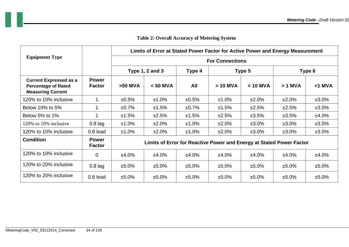
Metering Code –Draft Version 02
MeteringCode_V02_03112014_Corrected 34 of 128
Table 2: Overall Accuracy of Metering System
Equipment Type
Limits of Error at Stated Power Factor for Active Power and Energy Measurement
For Connections
Type 1, 2 and 3 Type 4 Type 5 Type 6
Current Expressed as a Percentage of Rated Measuring Current
Power Factor >50 MVA < 50 MVA All > 10 MVA < 10 MVA > 1 MVA <1 MVA
120% to 10% inclusive 1 ±0.5% ±1.0% ±0.5% ±1.0% ±2.0% ±2.0% ±3.0%
Below 10% to 5% 1 ±0.7% ±1.5% ±0.7% ±1.5% ±2.5% ±2.5% ±3.5%
Below 5% to 1% 1 ±1.5% ±2.5% ±1.5% ±2.5% ±3.5% ±3.5% ±4.0%
120% to 10% inclusive 0.8 lag ±1.0% ±2.0% ±1.0% ±2.0% ±3.0% ±3.0% ±3.5%
120% to 10% inclusive 0.8 lead ±1.0% ±2.0% ±1.0% ±2.0% ±3.0% ±3.0% ±3.5%
Condition Power Factor
Limits of Error for Reactive Power and Energy at Stated Power Factor
120% to 10% inclusive 0 ±4.0% ±4.0% ±4.0% ±4.0% ±4.0% ±4.0% ±4.0%
120% to 20% inclusive 0.8 lag ±5.0% ±5.0% ±5.0% ±5.0% ±5.0% ±5.0% ±5.0%
120% to 20% inclusive 0.8 lead ±5.0% ±5.0% ±5.0% ±5.0% ±5.0% ±5.0% ±5.0%

Metering Code – Version 02
35 of 128
3. SECTION: OWNERSHIP AND ASSOCIATED OBLIGATIONS
3.1. OWNERSHIP
3.1.1. Unless something different is agreed among Users, and authorised by the Market Operator, Ownership of Metering Systems shall conform to the following rules:
(a) Generation Stations directly connected to the Transmission Network (Either Type 1 or 6)
(i) Main Metering System shall be owned by the relevant Generation Company:
(ii) Check Metering, if Redundant Metering shall be owned by the relevant Generation Company
(iii) Check Metering, if Verification Metering, shall be owned by the TSP
(b) Distributors Connected to the Transmission Network (Type 2)
(i) Main Metering System shall be owned by the TSP:
(ii) Check Metering, if Redundant Metering shall be owned by the TSP
(iii) Check Metering, if Verification Metering, shall be owned by the relevant Disco
(c) Eligible Customers Connected to the Transmission Network (Either Type 3 or 6)
(i) Main Metering System shall be owned by the Eligible Customer:
(ii) Check Metering shall be owned by the TSP
(d) International Interconnections (Type 4)
(i) Main Metering System shall be owned by TCN, unless something different has been agreed in the relevant Interconnection Agreements
(ii) Ownership of Check Metering Systems shall be governed by the relevant Interconnection Agreement.
(e) Interfaces among different Discos (Type 5)
(i) Main and Check Metering System shall be owned by the relevant Discos.
3.1.2. The relevant owner shall be responsible for installing and maintaining his own metering equipment at the Connection Point, unless the User agrees with the Market Operator otherwise. For installations, site inspections, technical audits and maintenance the owner may utilize the services of any Metering Services Provider accredited by NERC.
3.1.3. Regardless of ownership, the Market Operator shall be responsible for approving the initial design, and for the testing, commissioning and sealing of any Commercial Metering System in Nigeria.
3.1.4. The User who owns the substation where the metering equipment is located shall provide the Market Operator with:
(a) 24 hour unrestricted access to the facilities where the Metering System is located
(b) adequate space for installing communications devices; and

Metering Code – Version 02
36 of 128
(c) reliable power supplies
3.1.5. Any remote communications to the metering equipment, Meters, Data Registers, and connection equipment will be the responsibility of the Market Operator. The Market Operator may agree, either with the System Operator or the TSP, as it considers suitable, on the operation and maintenance of the communication equipment, as well as the services associated with the remote reading.
3.2. PROPER ORDER
3.2.1. Each owner shall at its own cost keep in good working order, repair and condition all Meters and Metering Equipment in respect of which it is responsible, to the extent necessary to ensure the correct registration, recording and transmission of the required data relating to active and reactive energy, measured by the relevant Meters.
3.3. METERING INFORMATION REGISTER
3.3.1. The Market Operator will maintain a register of all Commercial Meters for settlement purposes at all Connection Points. This register will contain, but not be limited to:
(a) A unique meter identification/serial number.
(b) Location of the Commercial Meters and Metering Systems.
(c) The owner of each Commercial Meter.
(d) The identification of the Users concerned.
(e) Meter manufacturer, type and model.
(f) The specifications of metering equipment including accuracy.
(g) The adjustment factors including circuit losses to be applied.
(h) Metering System function (main, check, redundant or verification, export, import).
(i) Organization which issue the certification of the Meter and Metering Equipment
(j) Calibration and test performed on the Meters and/or the Metering Equipment at least during the last 5 years
3.3.2. Where the data in the metering information register indicates that the Commercial Meters or Metering Equipment do not comply with the requirements of this GMC, the Market Operator will advise the relevant owner of the non-compliance and such owner will rectify this situation forthwith unless a derogation is granted under the Chapter 1.3 of this GMC.

Metering Code – Version 02
37 of 128
4. SECTION: CERTIFICATION, CALIBRATION AND TESTING OF METERING SYSTEM
4.1. CERTIFICATION
4.1.1. Each User shall ensure that all Meters and Metering Equipments for which it is responsible shall, at the Effective Date and thereafter, be certified, calibrated or compensated in accordance with this Grid Metering Code in order to meet the accuracy requirements stated in Chapter 2.5 of this GMC.
4.1.2. All electricity Meters and Metering Equipment used in Nigeria shall be certified to the required accuracy and the standards specified in this Code, by an approved Metering Test Station.
4.1.3. Electricity Meters may be purchased ready certified (in which case independent certification shall be provided by the manufacturer), and shall be further certified in Nigeria by an authorised Meter Test Station. The adequacy of any certification issued by a manufacturer shall require prior approval by NERC, which may require performing additional test or verifications by an authorised Meter Test Station before issuing it.
4.1.4. Existing uncertified Meters and metering equipment shall be replaced by certified meters, or tested to confirm that their accuracy conforms to this GMC within the permitted recalibration interval by an authorised Meter Test Station. In the later case, the Meter Test Station which will perform the test will issue the required certification. All these tests shall be performed not later than one (1) year from the Effective Date the Code comes into effect.
4.1.5. Certifications of Meters issued by an authorised Meter Test Station or the approval issued by NERC in case of certifications issued by the manufacturers, as the case may be, shall be issued for a pre-definite period of time, which in no case will exceed fifteen (15) years, and shall clearly indicate the minimum required calibration tests and their frequency to maintain its validity. After that period the certification will expire, and the User shall replace the Meter, or ask for a new certification or an extension of the existing certification. This new certification or extension of the existing certification shall be issued by an authorised Meter Test Station, after the execution of tests and verifications the Metering Test Station considers relevant, and will contain different provisions regarding the frequency and characteristics of the calibration tests to be performed.
4.1.6. The minimum set of tests a manufacturer or an authorised Metering Test Station, as the case may be, shall perform to verify compliance with this GMC, and issuing the corresponding certification shall be in accordance with Appendix A of this GMC.
4.1.7. The Market Operator shall be granted access to such Metering Equipment upon reasonable notice and at reasonable times, in order to make or inspect any adjustments thereto and to attend any tests or inspection thereof required pursuant to this Grid Metering Code.
4.2. INITIAL CALIBRATION
4.2.1. All initial calibration of Meters and Metering Equipment shall be performed by authorised Meter Test Station. These tests shall be performed in accordance with the relevant IEC standards and shall confirm that Meter and Metering
Metering Code – Version 02
38 of 128
Equipment accuracy is within the limits stated in 2.5. A unique identifiable calibration record shall be provided before the connection is made live.
4.2.2. New voltage transformers and current transformers shall be calibrated by the Meter Test Station prior to installation at any site. Meter owners shall provide manufacturer’s test certificates to the Market Operator to show compliance with the accuracy standards.
4.3. COMMISSIONING TESTS
4.3.1. Where commissioning is required owing to the installation of new Metering Equipment or a modification of existing Metering Equipment, the relevant User must notify the Market Operator and any Users of the details of the new Metering System or changes to the existing system at least one (1) calendar month prior to the commissioning date. Where there is a change to a previously notified commissioning date, the User must notify the other parties of such change.
The User will, prior to the completion of commissioning, undertake testing in accordance with th is clause to ensure that the metering complies with the requirements of Chapter 2.5 and that such testing is witnessed by the nominated representative of the Market Operator. Such testing shall be in accordance with Appendix B of this GMC.
4.4. PERIODIC TESTS
4.4.1. Meters shall be periodically checked, as stipulated in sections 4.4.2. and 4.5 below, to ensure that meters are operated within the acceptable accuracy limits specified in this GMC so that the Users are able to prepare, calculate, assess and validate, and keep appropriate records of meter readings and where appropriate, challenge invoices on a prompt, comprehensive and accurate basis.
4.4.2. Regardless of the calibration requirements stated in the certification issued, the owner, upon an instruction by the Market Operator, will undertake the testing of the Meters and associated Metering Equipment, according the following schedules:
(a) Meters and Metering Equipment, at Connection Points of Type 1, 2, 3 or 4
(i) Meters: Every 2 years
(ii) CTs and VTs every 5 years. If the Meters are adjusted to compensate for errors in the CTs and VTs, then the CTs and VTs will also be tested every year.
(b) Meters and Metering Equipment, at Connection Points of Types 5 and 6
(i) Meters: Every 5 years
(ii) CTs and VTs every 5 years.
4.4.3. The above mentioned test shall be performed by an authorised Meter Test Station, and will be witnessed by the nominated representative of the Market Operator.
4.4.4. The cost of routine testing shall be met by the owner of the Metering System.

Metering Code – Version 02
39 of 128
4.5. OTHER PERIODIC TESTS
4.5.1. The owner of a Check Metering System or a Commercial Metering System will undertake calibration testing upon request by the Market Operator, relevant User or Associated User.
4.5.2. Where a User or Associated User reasonably believes the Commercial Metering System used for its data collection is operating outside the accuracy limits required by this GMC, it may request accuracy checks in accordance with Appendix A.
4.5.3. The cost of calibration testing must be met by the party requesting the test unless the test shows the accuracy of the Metering System does not comply with the requirements of this GMC, in which case the cost of the tests must be met by the owner of the Metering System, in addition to the costs that the owner must now incur to restore the Metering System to compliance with the GMC.
4.5.4. With regards to all testing in Nigeria, such work will only be undertaken by an authorized Metering Test Station. Where a User undertakes testing of its own Commercial Metering, then such testing shall be witnessed by a representative from the Market Operator and, if necessary, an Associated User. The User shall notify the Market Operator and the Associated User its intention to undertake such test with at least 15 business days in advance.
4.5.5. Results of the tests that show the Commercial Metering comply with this GMC will be sent to the Market Operator and the party that has requested the tests within 5 Business Days of the completion of such tests by the Meter Test Station.
4.6. TEST FAILURE
4.6.1. Where, following a test, the accuracy of the Metering System is shown not to comply with the requirements of this GMC, the certification issued for the Meter or Metering Equipment which has failed the test will automatically expire, and a new one will be required.
4.6.2. The owner will at its own cost:
(a) consult with the Market Operator and the Associated Users in regard to the errors found and the possible duration of the existence of the errors; and
(b) make repairs or replacements to the Metering System to restore the accuracy to the required standards.
4.6.3. Where a Commercial Metering System is found to be faulty, or non-compliant or outside the accuracy stated in Chapter 2.5, then the Market Operator and all Users and Associated Users that have an interest in this Metering System shall also be informed of the failure. Such notification shall include the plans by the owner to restore the Metering System to compliance with this GMC and the procedures to be followed to determine any estimated readings during the period, including any revised readings that were provided during the period that the Metering System was faulty or non-compliant.
4.6.4. In the event that a User cannot or does not comply with its obligations to repair, adjust or replace or renew any defective component, the Market Operator or the Associated User shall have the right to carry out such repair, adjustment, replacement or renewal and to recover its own costs, expenses and profit thereon from such User forthwith on demand (such profit to be based on a reasonable rate of return which shall be approved by NERC).
Metering Code – Version 02
40 of 128
5. SECTION: SECURITY AND DATA ACCESS
5.1. SEALING:
5.1.1. Following the Effective Date, or following any test or inspection carried out according to Section 4, the Commercial Meters shall be sealed by or on behalf of the Market Operator and, if necessary, the Associated User, except where sealing is impossible or impractical in the reasonable opinion of the Market Operator or the Interested User, having regard to the physical and electrical configuration at each Connection Point. Sealing shall be in accordance with the procedures stated in Appendix C.
5.1.2. Each User shall, following the Effective Date, make arrangements for all Metering Equipment as are capable of being made secure, to be sealed by the Market Operator or on its behalf, in accordance with the procedures stated in Appendix B, except where impossible or impractical having regard to the physical and electrical configuration at each Connection Point.
5.1.3. No seal applied pursuant to this Grid Metering Code shall be broken or removed except in the presence of, or with the prior consent, of the owner, the Market Operator and, if appropriate, the Associated User affixing the seal, or on whose behalf the seal has been affixed, unless it is necessary to do so in circumstances where:
(a) Both main and check meters are malfunctioning or there occurs a fire or other similar hazard and such removal is essential and such consent cannot immediately be obtained (provided that the person which has affixed the seal and which has not given such consent shall be informed forthwith thereafter) or
(b) Such action is required for the purposes of Provision 4.6.4.
where verbal consent is given it must be confirmed in writing forthwith.
5.1.4. All relevant Users shall ensure, so far as they are able, that physical access to Meters and Metering Equipment is, where practicable, restricted to personnel who are required to have such access for the proper performance of their duties and have received permission for such access. A record of any such access shall be maintained by the Market Operator and the User on whose premises the Meters and Metering Equipment are positioned. Copies of such records shall be provided to the Associated User on request. In addition all Meters and Metering Equipment, where practicable, must be made secure, if necessary by making the lock and keys subject to similar access restrictions.
5.1.5. Each User, Associated User or Market Operator shall control the issue of its own seals and sealing pliers, and shall keep an accurate register of all such pliers and the authorised persons to whom they are issued. All such pliers shall bear a distinctive mark.
5.2. ACCESS TO METERING DATA
5.2.1. With respect to any Commercial Metering only the owner of the Metering System will change data and settings within its metering equipment and in:
(a) The presence of the Market Operator, or its authorised representative; or with the written agreement of the Market Operator
Metering Code – Version 02
41 of 128
(b) The presence of the Associated User, or its authorised representative; or with written agreement of the Associated User.
5.2.2. With respect to any Commercial Metering, the owner of the Metering Systems will allow reading of the Meters by the Market Operator and by the User whose consumption is measured by the Metering Systems.
5.2.3. Access to Meter data by any User of the Commercial Metering Systems, including the provision of any remote access equipment required, will be at that User’s cost, unless agreed otherwise in writing by the parties concerned.

Metering Code – Version 02
42 of 128
PART 3: DISTRIBUTION METERING CODE
1. SECTION: INTRODUCTION
1.1. PURPOSE AND SCOPE
1.1.1. The purpose of this Distribution Metering Code (DMC) is to specify the technical and operational criteria, including the procedures to be complied with by the distributor, in carrying out its obligation to provide metering services to users at each metering point. It also applies to users in so far as their equipment may affect the distribution system.
1.1.2. The Distribution Metering Code applies to the following:
(a) Distributors
(b) Users connected to, or seeking connection to the Distribution System which in this part of the MC (the Distribution Metering Code) are:
(i) Customers connected to the LV Distribution Network
(ii) Customers connected to the MV distribution network, provided they are not Participants in the Market
(iii) Generation Connected to Distribution, provided they are not Participants in the Market
1.1.3. The Distributor shall:
(a) Own, install, verify, operate, maintain, inspect and replace all Metering Systems at Metering Points on the Distribution System. For installations, site inspections, technical audit and maintenance the owner may utilize the services of any Metering Services Provider accredited by NERC;
(b) Ensure that each Metering System installed on its Distribution System meets the performance, functional and technical requirements and applicable standards set out in this DMC;
(c) Ensure that each Metering System installed on its Distribution System is certified, is in working condition and has been tested for accuracy where so required by this MC;
(d) Retrieve data from each Metering System, other than Prepaid Meters, installed on its Distribution System for the purposes of billing and settlement;
(e) Process data retrieved from each Metering System, other than Prepaid Meters, installed on its Distribution System for the purposes of billing and settlement; and
(f) Notify NERC of all Metering Systems where the Distributor cannot comply with this Distribution Metering Code and shall seek derogation from the NERC, and NERC may or may not grant such derogation and may impose any conditions as it reasonably sees fit.

Metering Code – Version 02
43 of 128
1.2. DEROGATIONS
1.2.1 If a Distributor finds that an existing installation cannot comply with the standards contained in this DMC or cannot meet the required accuracy levels, it shall without delay report such non compliance to the NERC stating the reasons for non-compliance and the proposed remedy for this situation
1.2.2 Where a Distributor has received professional technical advice that the proposed equipment or existing equipment, although not fully meeting the standards as listed in Condition 2.4 Technical Requirements and Accuracy of Meters is capable of performing to the required levels of accuracy contained in th is DMC and/or then such advice and evidence of the performance of the equipment concerned, can be submitted to the Distributor or the NERC, as appropriate, as due process for a derogation request if the Distributor wishes.
1.2.3 Any request for derogations from any provision of the DMC by a Distributor shall contain:
(a) the issue number and the date of the DMC provision against which the derogation applies;
(b) identification of the Meters or Metering Equipment in respect of which a derogation applies and, if relevant, the nature and extent to which the derogation applies including alternate compliance provisions;
(c) identification of the provision with which the derogation applies;
(d) the reason for the non-compliance requiring derogation;
(e) proposed remedial actions, if any ;and
(f) the date by which the derogation ends if compliance will be achieved, or by which such derogation expires.
1.2.4 On receipt of any request for derogation, the NERC shall promptly consider such a request provided that the commission considers that the grounds for the derogation are reasonable. In its consideration of a derogation request, the commission may contact the relevant users to obtain clarifications of the request or request additional information or to discuss changes to the request, and review possible remedial actions to achieve compliance as soon as reasonably practicable.
1.2.5 To the extent of any derogation granted, the distributor shall be relieved from its obligation to comply with the applicable provision of the DMC and shall not be liable for failure to so comply but shall comply with any alternate provisions as set forth in the derogation.
1.2.6 NERC shall:
(a) keep a register of all derogations which have been granted, identifying the name of the Distributor in respect of whom the derogation has been granted, the relevant provision of the DMC and the period of the derogation; and
(b) on request from any User, provide a copy of such register of derogations to such User.

Metering Code – Version 02
44 of 128
(c) Where a material change in circumstance has occurred, a review of any existing derogations, and any derogations under consideration, may be initiated by NERC.

Metering Code – Version 02
45 of 128
2. SECTION: OBLIGATIONS
2.1. INSTALLATION AND REPLACEMENT OF METERING EQUIPMENT
2.1.4. The installation of Metering Equipment shall be made as close as practicable to the Connection Point, in accordance with the provisions of the Distribution Code.
2.1.5. The Distributor shall:
(a) Assign a unique identifier to the Metering System, cross-referenced to the location of the Metering System;
(b) Record the date of installation of the Metering System;
(c) Record the functionality of the Meter and the unit of measurement used to measure active or reactive Energy flowing through the Metering System or Maximum Load, as it corresponds;
(d) Record the identification of the ancillary equipment;
(e) Record any site-specific loss adjustment factors to be applied;
(f) Record redundancy details and sources of check metering data, where required by this Distribution Metering Code, and identification of the meters designated as the main Meter and as the Check Meter, if the later exists; and
(g) Record the initial Meter register reading.
(h) Ensure that the metering data stored in the Metering System is retrieved and, where a meter is removed, shall ensure that a final Meter reading is obtained.
2.1.6. The distributor may replace metering equipment for which it is responsible at any time after it has been installed, subject to the provisions of this distribution metering code. The distributor shall notify the user in advance of any replacement, unless that replacement is provided as part of urgent metering services.
2.1.7. The distributor shall maintain the following information for each metering system:
(a) Location of the Metering System;
(b) A record of any calibration of the Metering System including any test results made to the Metering System
(c) A record of any malfunction of the Metering System including any repairs made to the Metering System; and
(d) Documentation of Meter testing prior to installation.
2.1.8. The Distributor shall, on request, make available for each Metering System the information listed in DMC Paragraphs 2.1.3 and 2.1.4 to:
(a) The User;
(b) NERC.
Metering Code – Version 02
46 of 128
2.2. STANDARD METERING SYSTEMS
2.2.1. Each Metering Point shall be situated as close as is reasonably practicable to the relevant Connection Point.
2.2.2. .Standard Medium Voltage Metering Systems:
(a) Shall contain a Meter or more than one Meter, each of which is certified and complies with the standards stated in this DMC;
(b) Shall record Active Energy (kWh);
(c) Shall record Reactive Energy (kVArh);
(d) Shall record Maximum Load in the cases the applicable tariffs specifies that; and
(e) Shall have metering current and voltage transformers that are tested and comply with the standards stated in this DMC.
2.2.3. The rated short-time current rating shall not be less than
(a) 25kA for 3 seconds for MV Metering Points above 11 kV; or
(b) 20kA for 3 seconds for MV Metering Points at 11 kV and below.
2.2.4. For each circuit:
(a) Metering VT of accuracy class 1.0 or better with 110 volts secondary voltage and 100VA burden per phase for star-star shall be provided.
(b) Metering CT of accuracy class 0,5 or better with 5 amperes secondary current and 5VA burden shall be provided
2.2.5. Accuracy shall be as minimum class 2.0, provided that for new connections made after the date of approval of the first issue of the GMC the minimum accuracy class shall be 1.0
2.2.6. The Distributor may agree with the User the use of more accurate Meters or Metering System in particular cases of Medium or Large Connections.
2.2.7. Standard Low Voltage Metering Systems:
(a) Shall contain a Meter or more than one Meter, each of which complies with the standards in this DMC, being either 1-phase, 2-wire or 3-phase, 4-wire type of accuracy class 1.0 and metering current transformers, where applicable, of accuracy class 0.5 with 5 amperes secondary current and 5VA burden;
(b) Shall record Active Energy (kWh);
(c) May record Reactive Energy (kVArh);
(d) Shall record Maximum Load in the cases the applicable tariffs specifies that;
(e) Shall contain, where necessary, metering current transformer(s) provided by the Distributor which are tested and comply with the standards stated in this DMC; and
(f) Shall contain a suitable facility (including all necessary pre-wiring), provided by the Distributor, in which to house the Metering System.

Metering Code – Version 02
47 of 128
2.2.8. The Distributor may agree with the User the use of more accurate Meters or Metering Systems in particular cases of Medium or Large Connections.
2.2.9. Meters and Metering Equipment shall have a minimum service life of 10 years without maintenance from date of manufacture. The maximum service life of Meters and Metering Equipment shall be as specified by the manufacturer of such equipments, but in any case not longer than 20 years unless a larger value will be authorized by NERC.
2.3. ALTERNATIVES TO STANDARD METERING SYSTEMS
(a) Upon the request of a User, the Distributor may arrange for a Metering System to install a check meter, or to contain features or equipment in addition to those specified in this Distribution Metering Code provided that:
(b) The User agrees to pay the full costs of the additional features or equipment, including the costs of installation, operation, maintenance, repairs and replacement; and
(c) The additional features or equipment are compatible with the rest of the Metering System and do not lead to any degradation of the capability of the Metering System that would cause the Metering System to fail to meet any standards contained in this Distribution Metering Code.
2.4. TECHNICAL REQUIREMENTS AND ACCURACY OF METERS
2.4.1. The Distributor shall ensure that the accuracy of each Meter in each Metering System is certified by an authorised Meter Test Station and meets the applicable accuracy limits.
2.4.2. The limits of accuracy for the following classes of Meters shall be:
(a) ± 0.2% for class 0.2 S static watt-hour meters.
(b) ± 0.5% for class 0.5 S static watt-hour meters.
(c) ± 0.5% for class 0.5 watt-hour meters.
(d) ± 1.0% for class 1.0 watt-hour meters.
(e) ± 2.0% for class 2.0 watt-hour meters.
2.4.3. The accuracy of the various items of measuring equipment comprising Meters and Metering Systems shall conform to the relevant IEC standards or any equivalent Nigerian standards. The following IEC standards which are considered the minimum approved for use with this DMC are:
(a) IEC Standard 60044 Part 1 – Current transformers.
(b) IEC Standard 60044 Part 2 – Voltage transformers.
(c) IEC Standard 60044 Part 3 – Combined transformers.
(d) IEC Standard 60186 – Inductive voltage dividers (Only for Metering Systems installed before the Effective Date of this MC).
(e) IEC Standard 62053-22 - Alternating Current Static Watt-Hour Meters for Active Energy classes 0,2S and 0,5S

Metering Code – Version 02
48 of 128
(f) IEC Standard 62053-21 - Alternating Current Static Watt-Hour Meters for Active Energy classes 1 and 2
(g) IEC Standard 62053-23 - Alternating Current Static Var-Hour Meters for Reactive Energy (Class 2 and 3)
(h) IEC Standard 62052-11 - Electric Metering Equipments (AC). General requirements, tests and test conditions
(i) IEC Standard 62055-41 Electricity Metering. Prepayment Systems Part 41: Standard Transfer Specification. Application Layer protocol for one-way token transfer system.
(j) IEC Standard 62055-52 Electricity Metering. Prepayment Systems Part 52. Standard Transfer Specification- Physical protocol for two-way virtual token carrier for direct local connection.
SECTION: CERTIFICATION AND TESTS
3.1. CERTIFICATION OF NEW METERING INSTALLATIONS
3.1.1. NERC will issue recommendations for Meters and Metering Equipment procurement. These procurement recommendations should be used by the operators in order to purchase Meters and Metering Equipment of acceptable quality and performance. Regardless of the above mentioned recommendations, it is up to the Distributor responsibility to select the Meters and Metering Equipment which meet the accuracy and performance requirements contained in this DMC.
3.1.2. Every Meter Type (model) of meter intended to be used in a Metering Installation shall be certified (type-tested) by a Meter Test Station (MTS) or any other body as may be approved by NERC to perform this Type Tests, to confirm its specific characteristics and to prove that it complies with the requirements of relevant standards and accuracy class as outlined in Section 2. NERC shall permanently maintain registers with the list of certified Meter Types. The validity period of the type-test certificate issued by the MTS shall be two years for importers and five years for local manufacturers of metering systems respectively subject to renewal.
3.1.3. Prior to the installation, every Meter or Metering Equipment shall be:
(a) Submitted by the Distributor to a Meter Test Station, which has been accredited by NERC to perform Routine Tests and certification; or
(b) Received by the Distributor directly from a manufacturer with a test certificate endorsed by a Meter Test Station accredited by NERC to endorse manufacturer’s certifications.
3.1.4. Certifications of Meters or Metering Equipment issued by a manufacturer or an authorised Meter Test Station shall be issued for a pre-definite period of time, which in no case will exceed fifteen (15) years, and shall clearly indicate the minimum required calibration tests and their frequency to maintain its validity.

Metering Code – Version 02
49 of 128
3.1.5. Certification shall be confirmed by the attachment of a seal or certification sticker for the individual Meters and Metering Equipment. Certification of a Metering Installation will be valid as long as the certifications of all components of the Metering Installation remain valid.
3.1.6. Test certificates shall be retained by the Distributor whilst the Metering Equipment is in use, and for Metering Equipment that is no longer in use, for a minimum period of five (5) years after the Metering Equipment has been de-commissioned and rendered un-useable or scrapped. The Distributor shall submit copies of these certificates upon notice from NERC.
3.1.7 Meter Testing Arrangements: The test facilities of the Meter Test Stations shall be as follows:
(i) Automatic Test Bench with high accuracy static source and 0.02 Class electronic reference standard meter shall be used for testing and calibration of portable test sets
(ii) Portable test bench with static source and electronic reference meter of 0.2S Class shall be used for testing of meters on site.
(iii) The reference standard of class 0.02 meter of the test bench shall be biennially calibrated by an International Laboratory Accreditation Cooperation accredited laboratory to ensure traceability of measurement results.
3.1.8 Meter Test Stations shall comply with the following standards.
(i) IEC 17025: General Requirements for the Competence of Testing and Calibration Laboratories.
(ii) IEC 60376: Testing Equipment for Electrical Energy Meters.
3.1.7. NERC shall permanently maintain a register of authorized Meter Test Stations, accredited to perform either:
(a) Type Tests certification
(b) Routine Tests certification
(c) Endorsement of manufacturer’s certifications
(d) Calibration Test certifications
On request from any Distributor or User, NERC shall provide a copy of such register to such Distributor or User
3.1.8. NERC will issue directives with the procedures to be applied and tests to be conducted to:
(a) Issue a Type Test certification
(b) Issue a Routine Test certification
(c) Issue a Calibration Test certification
(d) Endorsement of a manufacturer’s certification
These directives could specify that, in cases of sampling testing of more than one meter, a pre-defined percentage of Meters shall comply with more stringent accuracy. Calibration reports will be required as part of the input to certification

Metering Code – Version 02
50 of 128
reports for Metering Installations, which should demonstrate that the overall accuracy requirements stated in this MC are met.
3.2. CERTIFICATION OF EXISTING INSTALLATIONS
3.2.1. Meters and Metering Equipment already installed in the Distribution System at the Effective Date shall be considered either:
(a) Certified, if at NERC discretion, the installed Meter and Metering Equipment have undergone calibration or verification tests which are deemed compatible with the provisions of this MC. In this case NERC will determine the additional period of time that this certification will remain valid.
(b) Non certified, otherwise.
3.2.2. In order to obtain NERC’s certifications indicated in paragraph 3.2.1 (a), the Distributor shall submit, within the first twelve (12) months of the Effective Date of this DMC, a requirement to NERC with all supporting documentation the Distributor considers suitable to support its claim. NERC will evaluate the submitted documentation, require clarifications and conduct independent analysis which should include testing, by an authorised Meter Test Station, of specific samples of the Meters or Metering Equipment, before issuing or rejecting the required certification.
3.2.3. For uncertified Meters or Metering Equipment, the Distributors shall replace the involved equipments or obtain a valid certification according with the procedures stated in Condition 3.3 Re-certification. The Distributor shall replace the equipment or obtain the above mentioned certification within eight (8) years of Effective date
3.3. RE-CERTIFICATION
3.3.1. Before the certification of a Metering Installation, or of any of its components, has expired, the Metering Installation should require re-certification, by an authorized Meter Test Station accredited to perform Calibration Tests certifications.
3.3.2. Certification of the overall Metering Installation expires when the individual certification of any one of its components expires.
3.3.3. Any such component would be recertified by removal and tests, testing online, or replacement, as appropriate. If any part of the wiring of the Metering Installation is modified, or if additional components are connected to the Metering Installation (other than testing or monitoring equipment temporarily connected via the test block), the certification of the Metering Installation should be deemed to be cancelled until the tests and checks prescribed by this MC have been satisfactorily carried out by an authorized Meter Test Station.
3.4. INSPECTION AND PERIODIC TESTS
3.4.1. The Distributor shall ensure that each Metering System is inspected according to the minimum frequencies specified in following Table:
Type of Metering System Frequency
Medium Voltage Low Voltage, including prepayment
Once every year
Once every 3 years
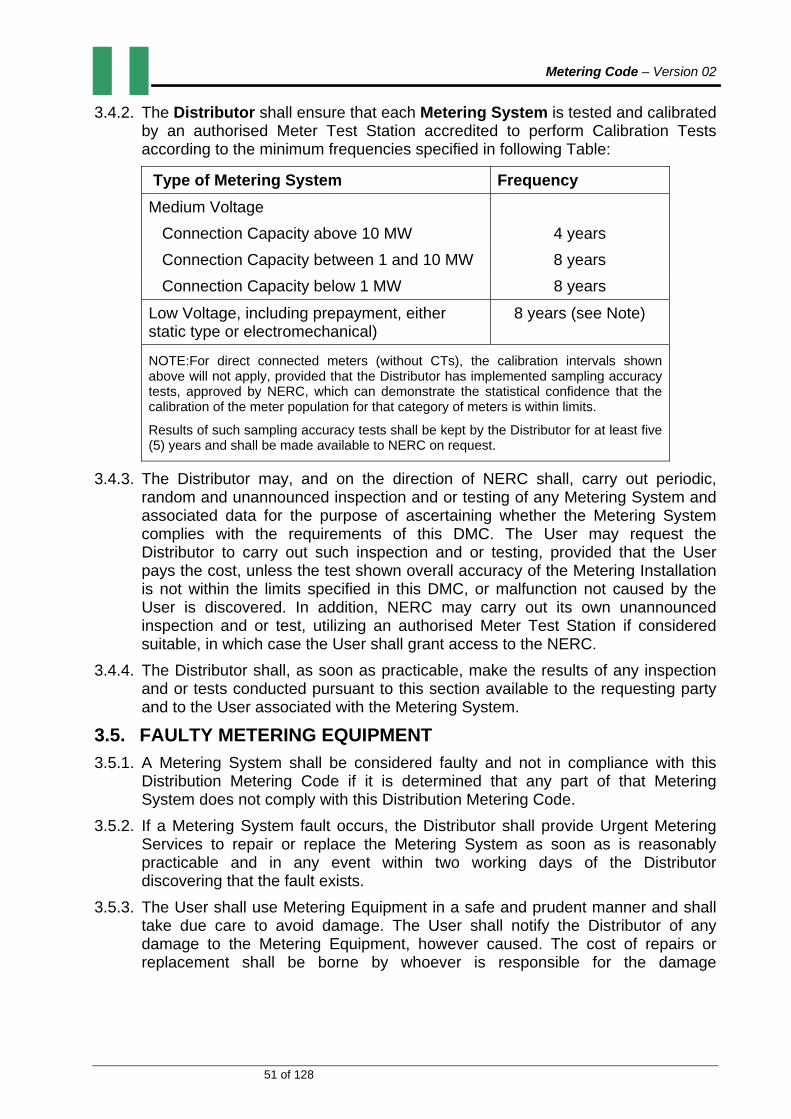
Metering Code – Version 02
51 of 128
3.4.2. The Distributor shall ensure that each Metering System is tested and calibrated by an authorised Meter Test Station accredited to perform Calibration Tests according to the minimum frequencies specified in following Table:
Type of Metering System Frequency
Medium Voltage
Connection Capacity above 10 MW 4 years
Connection Capacity between 1 and 10 MW 8 years
Connection Capacity below 1 MW 8 years
Low Voltage, including prepayment, either static type or electromechanical)
8 years (see Note)
NOTE:For direct connected meters (without CTs), the calibration intervals shown above will not apply, provided that the Distributor has implemented sampling accuracy tests, approved by NERC, which can demonstrate the statistical confidence that the calibration of the meter population for that category of meters is within limits.
Results of such sampling accuracy tests shall be kept by the Distributor for at least five (5) years and shall be made available to NERC on request.
3.4.3. The Distributor may, and on the direction of NERC shall, carry out periodic, random and unannounced inspection and or testing of any Metering System and associated data for the purpose of ascertaining whether the Metering System complies with the requirements of this DMC. The User may request the Distributor to carry out such inspection and or testing, provided that the User pays the cost, unless the test shown overall accuracy of the Metering Installation is not within the limits specified in this DMC, or malfunction not caused by the User is discovered. In addition, NERC may carry out its own unannounced inspection and or test, utilizing an authorised Meter Test Station if considered suitable, in which case the User shall grant access to the NERC.
3.4.4. The Distributor shall, as soon as practicable, make the results of any inspection and or tests conducted pursuant to this section available to the requesting party and to the User associated with the Metering System.
3.5. FAULTY METERING EQUIPMENT
3.5.1. A Metering System shall be considered faulty and not in compliance with this Distribution Metering Code if it is determined that any part of that Metering System does not comply with this Distribution Metering Code.
3.5.2. If a Metering System fault occurs, the Distributor shall provide Urgent Metering Services to repair or replace the Metering System as soon as is reasonably practicable and in any event within two working days of the Distributor discovering that the fault exists.
3.5.3. The User shall use Metering Equipment in a safe and prudent manner and shall take due care to avoid damage. The User shall notify the Distributor of any damage to the Metering Equipment, however caused. The cost of repairs or replacement shall be borne by whoever is responsible for the damage

Metering Code – Version 02
52 of 128
determined through an investigation by the Distributor. In the case of a dispute as to who is responsible, the matter shall be referred to the MCRP for resolution.
3.5.4. The Distributor shall ensure that suitable data is obtained or estimated for the period of time commencing when a Meter or Metering Equipment becomes faulty until the completion of the repair or replacement.
3.5.5. The Distributor shall record all relevant Meter parameters for a replacement Meter in that Metering System.
Metering Code – Version 02
53 of 128
4. SECTION: ACCESS AND SECURIY
4.1. ACCESS TO METERING SYSTEMS
4.1.1. The User shall grant access to the Distributor to enable the Distributor to fulfil its obligations under this Distribution Metering Code. This right of access is conditional upon:
(a) Where practicable, prior notice by the Distributor; and
(b) The production of identification by the Distributor’s staff or contractor.
4.1.2. Prior arrangement by the Distributor shall not be required in respect of routine Meter reading, or periodic, random and unannounced audits required by DMC Section 3.4.3, or when the Distributor is performing Urgent Metering Services.
4.2. SECURITY OF METERING SYSTEMS
4.2.1. The Distributor shall, so far as is reasonably practicable, maintain the security of the metering data stored in or obtained from each Metering System.
4.2.2. Appropriate seals shall be applied to each Metering System. Seals shall be replaced following works requiring the removal of any seals. The Distributor’s procedures for the control of seals and sealing pliers shall be subject to approval by the NERC.
4.2.3. The Distributor shall, so far as is reasonably practicable, ensure that physical access to each Meter contained in each Metering System is protected by:
(a) Sealing all associated links, circuits, data storage and data processing systems;
(b) Ensuring that the Metering System meets the requirements for the security of Metering Systems set out in this Distribution Metering Code.
(c) The Distributor shall use reasonable endeavours to ensure that all metering data within each Metering System is secure.
Metering Code – Version 02
54 of 128
5. SECTION: METER READING AND DATA MANAGEMENT
5.1. METER READING
5.1.1. The Distributor shall schedule at least once in four (4) months reading for all manually read meters.
5.1.2. For kilowatt-hour meters, the Distributor shall verify at each Meter reading that the Meter identification number on the Meter matches the Meter identification number on the Meter reading schedule.
5.1.3. The Distributor shall record:
(a) The Meter identification number;
(b) The Meter reading and read date at the beginning of the Meter reading period;
(c) The Meter reading and read date at the end of the Meter reading period;
(d) The cumulative Active Energy (kWh) recorded during the Meter reading period;
(e) Where the User is billed for Reactive Energy, the cumulative Reactive Energy (kVArh) recorded during the Meter reading period;
(f) Where the User is billed for maximum Active Power, the maximum Active Power recorded during the Meter reading period;
(g) Where the User is billed for maximum Reactive Power, the maximum Reactive Power recorded during the Meter reading period; and
(h) Details of any Meter alarms that were recorded during the period (e.g., system outages, VT failure).
5.2. REMOTE METERING EQUIPMENT
5.2.1. The Distributor shall specify the type of equipment to be used for communication with remote meters.
5.2.2. The Distributor shall conduct such tests as it deems necessary to verify production or consumption recorded at each Metering Point.
5.3. DATA MANAGEMENT
5.3.1. The Distributor shall:
(a) Maintain a metering data registry that contains usage data for each User and data required for settlement purposes in respect of each Metering System;
(b) Validate metering data for each Metering System;
(c) Estimate usage when Meter readings are not available, inaccurate, or otherwise not suitable for settlement purposes;
(d) Apply adjustments to metering data to account for system losses and unaccounted for energy;
(e) Aggregate metering data for settlement and loss calculation purposes; and
Metering Code – Version 02
55 of 128
(f) Use reasonable endeavours to maintain the security and confidentiality of the metering data.
5.4. DATA REGISTRATION
5.4.1. The Distributor shall establish and maintain a register that contains the following information for each Metering System:
(a) A unique identifier assigned by the Distributor to the Metering System cross-referenced to the location of the Metering System and cross referenced to the User’s account;
(b) The date of installation of the Metering System;
(c) The functionality of the Meter and the unit of measurement used to measure Energy flowing through the Metering System (e.g., kWh meter, kVArh meter);
(d) The Meter Type installed
(e) Identification of the ancillary equipment;
(f) Any site-specific adjustment factors to be applied, including a cross reference to the unique identifier specified in (a) above;
(g) The existence of redundancy and sources of check metering data, where required by this DMC, and identification of the meters designated as the Main Meter and as the Check Meter;
(h) Data for each Meter following completion of the validation and estimation procedures;
(i) Billing data for each Meter following completion of adjustments for losses and unaccounted for energy; and
(j) The data covering a period of not less than twelve months which shall be immediately accessible in electronic form.
5.5. DATA VALIDATION AND LOSS ADJUSTMENT FACTORS
5.5.1. The Distributor shall:
(a) Have in place data validation procedures and loss adjustment calculation methodologies approved by NERC;
(b) Where necessary, determine site-specific loss adjustment factors for each Metering System;
(c) Multiply each valid reading by the appropriate loss adjustment factor to produce loss adjusted production or consumption; and
(d) Shall maintain both unadjusted and loss-adjusted values in the metering data registry in respect of each Metering System.

Metering Code – Version 02
56 of 128
INHERENT POWERS OF THE COMMISSION
(a) The Commission may from time to time amend or repeal the provisions of this Metering Code and the Appendices thereto as it may determine.
(b) Nothing in this Metering Code shall prohibit the Commission from adopting in conformity with the provisions of the Act, any procedure which is at variance with any of the provisions of herein, provided that the Commission is of the opinion that in the special circumstances of the matter and for reasons to be recorded in writing, it deems it just or expedient that such procedure is proper for dealing with the matter.
THE COMMON SEAL OF
NIGERIAN ELECTRICITY REGULATORY COMMISSION
Was affixed pursuant to the ORDER OF THE COMMISSION
On this ……............................ day of…….........................................…………… 2013.
Dr. Sam Amadi
CHAIRMAN/CEO
Metering Code – Version 02
57 of 128
METERING CODE – APPENDICES
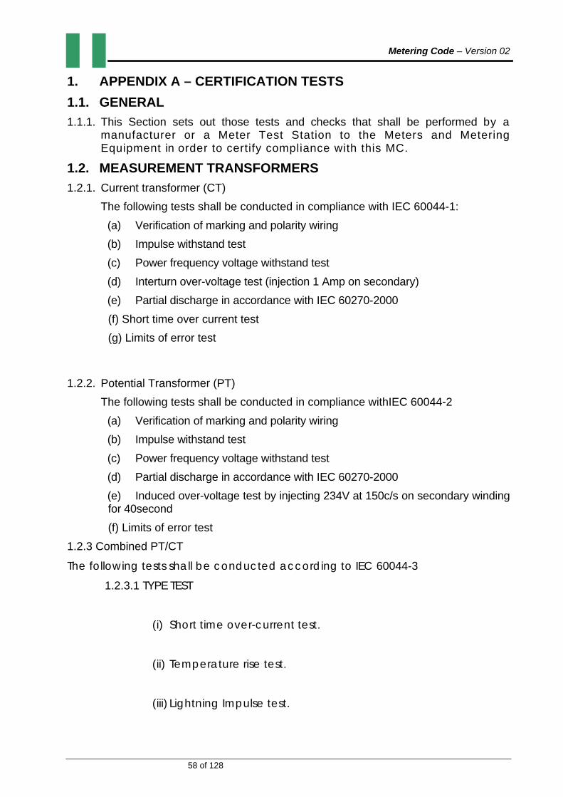
Metering Code – Version 02
58 of 128
1. APPENDIX A – CERTIFICATION TESTS
1.1. GENERAL
1.1.1. This Section sets out those tests and checks that shall be performed by a manufacturer or a Meter Test Station to the Meters and Metering Equipment in order to certify compliance with this MC.
1.2. MEASUREMENT TRANSFORMERS
1.2.1. Current transformer (CT)
The following tests shall be conducted in compliance with IEC 60044-1:
(a) Verification of marking and polarity wiring
(b) Impulse withstand test
(c) Power frequency voltage withstand test
(d) Interturn over-voltage test (injection 1 Amp on secondary)
(e) Partial discharge in accordance with IEC 60270-2000
(f) Short time over current test
(g) Limits of error test
1.2.2. Potential Transformer (PT)
The following tests shall be conducted in compliance withIEC 60044-2
(a) Verification of marking and polarity wiring
(b) Impulse withstand test
(c) Power frequency voltage withstand test
(d) Partial discharge in accordance with IEC 60270-2000
(e) Induced over-voltage test by injecting 234V at 150c/s on secondary winding for 40second
(f) Limits of error test
1.2.3 Combined PT/CT
The following tests shall be conducted according to IEC 60044-3
1.2.3.1 TYPE TEST
(i) Short time over-current test.
(ii) Temperature rise test.
(iii) Lightning Impulse test.

Metering Code – Version 02
59 of 128
(iv) Switching Impulse test.
(v) Wet Test for outdoor transformer.
(vi) Short CCT withstand capability on PT.
(vii) Limits of error test.
(viii) Measurement of the radio interference voltage.
1.2.3.2 ROUTINE TEST
(i) Verification of terminal marking.
(ii) Power frequency withstand test on the primary.
(iii) Partial discharge measurement for PT in accordance with IEC 60270 – 2000.
(iv) Power frequency withstand test on secondary.
(v) Power frequency withstand test between sections.
(vi) Inter-turn over-voltage test for CT.
(vii) Limits of error test.|

Metering Code – Version 02
60 of 128
1.3. METERS
In accordance with standards mentioned in this code, samples of all meters shall satisfactorily fulfil the requirements of the Type Tests.
The Type Tests required to be carried out are as listed below;
Nr. Tests Electro‐mechanical meters
Electronic meters
1 Test of insulation properties
Impulses voltage tests
AC voltage tests
x
x
x
x
2
Tests of accuracy requirements
Test of meter constant
Test of starting condition
Test of no‐load condition
Test of influence quantities
Repeatability of error test
x
x
x
x
x
x
x
x
x
x
3 Tests of electrical requirements
Test of power consumption
Test of influence of supply voltage
Test influence of short‐time over‐currents
Test of influence of self‐heating
Test of influence of heating
Test of immunity to earth fault
x
x
x
x
x
x
x
x
x
x
x
x
4 Test for electromagnetic compatibility (EMC)
Radio interference suppression
Fast transient burst test
Damped oscillatory waves immunity test
Test of immunity to conducted disturbances,
x
x
x
x

Metering Code – Version 02
61 of 128
induced by radio‐frequency fields
Test of immunity to electrostatic discharges
Surge immunity test
x
x
5 Tests of the effect of the climatic environments
Dry heat test
Cold test
Damp heat, cyclic test
Solar radiation test
x
x
x
x
x
x
x
x
6 Mechanical Tests
Vibration test
Shock test
Spring hammer test
Tests of protection against penetration of dust and water
Test of resistance to heat and fire
x
x
x
x
x
x
x
x
x
x
ROUTINE TESTS
Upon supply, all Meters are required to fulfill requirements of Routine Test comprising the following;
A.C High Voltage Test
Test of Meter Constant
Test of Starting Condition
Test of No Load Condition
Test of Influence Quantities

Metering Code – Version 02
62 of 128
ACCEPTANCE TESTS
The following tests shall be conducted for meter samples for the purpose of Acceptance Test Certification:
Test of Starting Condition
Test of No Load Condition
Test of Power Consumption
Voltage Variation Test
Frequency Variation Test
Test of Influence Quantities
Repeatability of Error Test
Power Frequency and Impulse Voltage Withstand Tests
Samples of meters shall be selected from the lot (batch) using the Single Plan Method below:
Batch Size Sample Size Acceptance/ Rejection
Criterion
1‐50 All No. No.
51‐150 13 0 1
151‐500 50 1 2
501‐1200 80 2 3

Metering Code – Version 02
63 of 128
2. APPENDIX B – COMMISSIONING TESTS
2.1. GENERAL
2.1.1. This Section sets out those tests and checks that shall be included in the metering commissioning programme. Metering equipment shall in addition have basic tests carried out on earthing, insulation and continuity, together with such other tests that would normally be conducted in accordance with Prudent Utility Practice. In addition during the commissioning of new or modified parts of the installation including the meter, voltage transformer, current transformer and data recorders then these shall be confirmed as being in accordance with the approved drawings to avoid equipment with for example a wrong ratio or a wrong specification being inadvertently connected.
2.2. MEASUREMENT TRANSFORMERS
2.2.1. For all installations with new/replaced measurement transformers the Market Operator and/or User shall ensure that from site and/or factory tests and inspections the following are confirmed and recorded:
(a) Details of the installed units, including serial numbers, rating, accuracy classes, ratio(s).
(b) CT ratio and polarity for selected tap.
(c) VT ratio and phasing for each winding.
2.2.2. For installations with existing measurement transformers the Market Operator and/or User shall ensure that, wherever practically possible, items a, b and c above are implemented but as a minimum must confirm and record VT and CT ratios. If it is not possible to confirm the CT ratio on site then the reason must be recorded on the commissioning record and details must be obtained from any relevant other party.
2.3. MEASUREMENT TRANSFORMERS LEADS AND BURDENS
2.3.1. For all installations the Market Operator and/or User shall wherever practically possible:
(a) Confirm that the VT and CT connections are correct.
(b) Confirm that the VT and CT burden ratings are not exceeded.
(c) Determine and record the value of any burdens (including any non-Commercial Metering burdens) necessary to provide evidence of the overall metering accuracy.
2.4. METERING
GENERAL TESTS AND CHECKS
2.4.1. The following may be performed on-site or elsewhere (for example, factory, Meter Test Station, laboratory, etc.):

Metering Code – Version 02
64 of 128
(a) Record the Metering System details required by the Data Collection System.
(b) Confirm that the VT/CT ratios applied to the Meter(s) agree with the site measurement transformer ratios.
(c) Confirm correct operation of Meter test terminal blocks where these are fitted (for example, CT/VT operated metering).
(d) Check that all cabling and wiring of the new or modified installation is correct and is clearly marked and or colour coded.
(e) Confirm that meter registers advance (and that output pulses are produced for Meters which are linked to separate outstations) for import and where appropriate export flow directions.
(f) Confirm Meter operation separately for each phase current and for normal polyphase current operation.
(g) Where separate outstations are used confirm the Meter to outstation channel allocations and that the Meter units per pulse values or equivalent data are correct.
(h) Confirm that the local interrogation facility (Meter or outstation) and local display etc., operate correctly.
SITE TESTS
2.4.2. The following tests shall be performed on site:
(a) Check any site cabling, wiring, connections not previously checked under clause the General Tests above.
(b) Confirm that Meter/outstation is set to UTC + 1 within ± 5 seconds.
(c) Check that the voltage and the phase rotation of the measurement supply at the Meter terminals are correct.
(d) Record Meter starts readings (including date and time of readings).
(e) Wherever practicable, a primary prevailing load test (or where necessary a primary injection test) shall be performed which confirms that the Meter(s) is registering the correct primary energy values and that the overall installation and operation of the Metering System is correct.
(f) Where for practical or safety reasons the previous site test (e) above is not possible then the reason shall be recorded on the commissioning record and a secondary prevailing load or injection test shall be performed to confirm that the Meter registration is correct including, where applicable, any Meter VT/CT ratios. In such cases the VT/CT ratios shall have been determined separately as detailed.
(g) Record values of the Meter(s)/outstation(s) displayed or stored data (at a minimum one complete half-hour value with the associated date and time of the reading) on the commissioning record.
(h) Confirm the operation of metering equipment alarms (not data alarm or flags in the transmitted data).
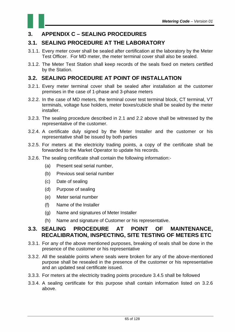
Metering Code – Version 01
65 of 128
3. APPENDIX C – SEALING PROCEDURES
3.1. SEALING PROCEDURE AT THE LABORATORY
3.1.1. Every meter cover shall be sealed after certification at the laboratory by the Meter Test Officer. For MD meter, the meter terminal cover shall also be sealed.
3.1.2. The Meter Test Station shall keep records of the seals fixed on meters certified by the Station.
3.2. SEALING PROCEDURE AT POINT OF INSTALLATION
3.2.1. Every meter terminal cover shall be sealed after installation at the customer premises in the case of 1-phase and 3-phase meters
3.2.2. In the case of MD meters, the terminal cover test terminal block, CT terminal, VT terminals, voltage fuse holders, meter boxes/cubicle shall be sealed by the meter installer.
3.2.3. The sealing procedure described in 2.1 and 2.2 above shall be witnessed by the representative of the customer.
3.2.4. A certificate duly signed by the Meter Installer and the customer or his representative shall be issued by both parties
3.2.5. For meters at the electricity trading points, a copy of the certificate shall be forwarded to the Market Operator to update his records.
3.2.6. The sealing certificate shall contain the following information:-
(a) Present seal serial number,
(b) Previous seal serial number
(c) Date of sealing
(d) Purpose of sealing
(e) Meter serial number
(f) Name of the Installer
(g) Name and signatures of Meter Installer
(h) Name and signature of Customer or his representative.
3.3. SEALING PROCEDURE AT POINT OF MAINTENANCE, RECALIBRATION, INSPECTING, SITE TESTING OF METERS ETC
3.3.1. For any of the above mentioned purposes, breaking of seals shall be done in the presence of the customer or his representative
3.3.2. All the sealable points where seals were broken for any of the above-mentioned purpose shall be resealed in the presence of the customer or his representative and an updated seal certificate issued.
3.3.3. For meters at the electricity trading points procedure 3.4.5 shall be followed
3.3.4. A sealing certificate for this purpose shall contain information listed on 3.2.6 above.

Metering Code – Version 01
66 of 128
3.4. SEALS SPECIFICATIONS
Type - Compressible or non-compressible type
Material - Plastic with embossed serial number
Temperature Range - To withstand operating temperature of up to 70oc
Colour -To be of any colour
Wire Dimension - Not more than 2.5mm2 cross-sectional area. Average Break Strength - Reasonably large break strength 3.5. SEALING POINTS
Every metering system shall be sealed at the following sealing points:-
(i) Meter cover (ii) Meter terminal cover (iii) Meter battery cover (iv) Test terminal cover (v) Voltage fuses & Links (vi) CTs and VTs terminals (vii) Associated circuits, and (viii) Metering box or cubicles

Metering Code – Version 01
67 of 128
4. APPENDIX D. TECHNICAL SPECIFICATIONS FOR METERS AND METERING ACCESSORIES.
4.1. GENERAL
The technical specifications enunciated herein are a summary of minimum requirements for energy meters and metering accessories approved for use in Nigeria’s electricity network. It is aimed at promoting quality of energy metering in Nigeria to ensure fair play in energy transactions among utilities and customers and safety of all meter users.
The specifications cover the following:
i. Electromechanical Meters ii. Electronic Meters iii. Prepaid Meters iv. Automatic Meter Reading Systems (AMR) v. Smart Metering vi. Current Limiters vii. Metering Accessories viii. Metering Panels
4.1.1. This Code recognizes all the existing meter technologies however the framework for future deployment of meters shall be smart metering.
4.1.2. The specifications are prepared in accordance with the following International Standards:
i. IEC 62052-11 ii. IEC 62053-11,21,22 and 23
iii. IEC 62055-41 and 52 iv. IEC 62056 v. IEC 60044-1,2 and 3
4.1.3. ATTRIBUTES OF COMMUNICATION MEDIA
i. The communication media shall be immune to environmental/man-
made disturbances.
ii. The communication media shall be tamper resistant.
iii. Shall have sufficient security at the physical and data level.
Iv. The communication media shall be reliable with very high up-time.

Metering Code – Version 01
68 of 128
v. The cost of infrastructure and variable cost of the communication
media shall be relatively low.
4.2. CERTIFICATION AUTHORITY
The calibration of meters shall be done at any approved Meter Test Station.
4.3. TECHNICAL SPECIFICATIONS FOR ELECTRO-MECHANICAL METERS
4.3.1. SINGLE PHASE ELECTRO-MECHANICAL METER
S/N PARAMETERS TECHNICAL REQUIREMENT
1 Nominal Voltage 240V AC,2 Wire System
2 Operating Voltage -40% to +10% Nominal voltage
3 Accuracy Class 2
4 Current Rating 5(60)A
5 Frequency 50HZ ±2%
6 Relative Humidity 96% at 450C Non- Condensing
7 Operating Temp. Up to 600C
8 Storage Temp. Up to 700C
9 Energy Register Cyclometer type with at least 5 No Wheels. Bold digits of not less than 9.0 x 4.5mm size, clearly marked in KWh
10 Graduation of Roller scale 10,000;1,000;100;10;1
11 Terminal Hole of 9mm diameter. Extended terminal cover with provision for adequate sealing. External connection diagram on the terminal cover
12 Rotor Type Bottom bearing of magnetic edge and upper surface of the disc shall be graduated or marked.
13 EMC Susceptibility According to IEC 61036,IEC 61268

Metering Code – Version 01
69 of 128
14 Connection Ph, Neutral, Neutral, Ph (Symmetrical)
15 Name Plate Provision of the inscription of Utility Property & serial number
16 Casing/Cover Material Fire retardant-Bakelite or Polycarbonate
17 Carrying Handle Must be provided
18 Meter Constant Must be stated
19 Surge withstand voltage Not less than 6KV
20 Insulation resistance 2KV for 1 min
21 Mounting hook Must be provided
22 Burden ≤ 2VA
23 Sealing Provision must be adequate to prevent tampering
24 Life Span 15 years
4.3.2. POLY-PHASE ELECTRO-MECHANICAL METER
S/N PARAMETERS TECHNICAL REQUIREMENT
1 Nominal Voltage 3 x 240/415V AC, Three –phase four Wire System for use in balanced or unbalanced load conditions incorporated with anti-reverse device
2 Operating Voltage -40% to +10% Nominal voltage
3 Accuracy Class 2
4 Current Rating 3 x 10(60)A
5 Frequency 50HZ ±2%
6 Relative Humidity 96% at 450C Non- Condensing
7 Operating Temp. Up to 600C

Metering Code – Version 01
70 of 128
8 Storage Temp. Up to 700C
9 Energy Register Cyclometer type with at least 6 No Wheels. Bold digits of not less than 9.0 x 4.5mm size, clearly marked in KWh
10 Graduation of Roller scale
100,000,10,000;1,000;100;10;1
11 Terminal Hole of 9mm diameter. Extended terminal cover with provision for adequate sealing. External connection diagram on the terminal cover
12 Rotor Type Bottom bearing of magnetic edge and upper surface of the disc shall be graduated or marked.
13 EMC Susceptibility
According to IEC 61036,IEC 61268
14 Connection Ph, Load, Ph, Load, Ph, Load: N,N
15 Name Plate Provision of the inscription of Utility name & serial number
16 Casing/Cover Material
Fire retardant-Bakelite or Polycarbonate
17 Carrying Handle Must be provided
18 Meter Constant Must be stated
19 Surge withstand voltage
Not less than 6Kv
20 Insulation resistance
2KV for 1 min
21 Mounting hook Must be provided
22 Burden 2VA/Phase, maximum
23 Sealing Provision must be adequate to prevent tampering
24 Life Span 15 years

Metering Code – Version 01
71 of 128
4.4. TECHNICAL SPECIFICATIONS FOR STATIC/ELECTRONIC METERS
4.4.1. GENERAL CONSTRUCTION AND COMPONENT SPECIFICATIONS FOR STATIC ENERGY METERS
S/NO. PARAMETERS TECHNICAL REQUIEMENTS
1. Body of Meter Bakelite or Polycarbonate
2. Terminal Block Made of polycarbonate grade and shall form integral part of the Meter base, brass or copper current terminals with star head brass screws as well as bimetallic contacts.
3. Terminal cover Transparent terminal cover with external provision of sealing through sealing screws.
4. Diagram of connections
Diagram of external connections to be shown inside the terminal cover.
5. Marking on name plates
Meter shall have clearly visible, indelible and distinct name plate.
6. Meter Sealing One seal shall be affixed on one side of Meter body
7. Guarantee/Warranty
5 years
8. Resistance to heat and fire
The terminal block of Meter case shall be protected against the spread of fire. They shall not be ignited by thermal overload of live parts in contact with them.
4.4.2. OTHER GENERAL COMPONENT SPECIFICATIONS
S/NO COMPONENT FUNCTION
REQUIREMENT
1. Measurement or computing chips
The Measurement or computing chips used in the Meter shall be with the Surface mount type along with the ASCIIs.
2. Memory Chips The memory chips shall not be affected by the

Metering Code – Version 01
72 of 128
external parameters like sparking, high voltage spikes or electrostatic discharges.
3. Display Modules a) The display modules shall be well protected from the external Ultra-Violet (UV) radiations.
b) The display visibility shall be sufficient to read the Meter mounted at a height of 0.5 metre as well as at the height of 2 metres.
4. Communication Modules
Communication modules shall be compatible for the two RS 232/485 ports one for optical port for communication with Meter reading instruments & the other, for the hardware. RS 232/485 port to communicate with various modems for AMR such as mobile telephony, radio frequency, fixed line, satellite, or power line communication technology with IEC 62056-21 DLMS/COSEM protocol.
5. Optical Port Optical port shall be used to transfer the Meter data to Meter reading instrument. The mechanical construction of the port shall be such to facilitate the data transfer easily.
6. Power Supply The power supply shall be with the capabilities as per the relevant standards. The power supply unit of the Meter shall not be affected in case the maximum voltage of the system appears to the terminals due to faults or due to wrong connections.
7. Electronic Components
The active and passive components shall be of the surface mount type to be handled and soldered by the state of the art assembly processes. The components shall be positioned in such a way that the leads of components shall not be under stress and not touching the internal wires.
8. Mechanical Parts The internal electrical components shall be of electrolytic copper and shall be protected from corrosion, rust, etc.
The other mechanical components shall be protected from rust, corrosion, etc.by suitable plating and painting methods.
9. Battery Lithium with minimum guaranteed life of 10 years and can last without recharging for 60

Metering Code – Version 01
73 of 128
days.
10. RTC & Micro Controller
The accuracy of Real Time Clock shall be as per relevant IEC standards
11. P.C.B Glass Epoxy, fire resistance grade FR4, with minimum thickness of 1.6mm
4.4.3. GENERAL TAMPER AND ANTI-FRAUD DETECTION/EVIDENCE FEATURES
The Meter shall log minimum of 225 tamper events, compartment-wise division of each event and their persistence time shall be indicated.
The meter shall not be affected by any remote tamper control device and shall continue recording energy under any one or combinations of the following conditions:
i. Phase sequence reversal: The Meters shall work accurately irrespective of the phase sequence of the supply.
ii. Detection of missing potential: In case someone intentionally takes out a potential lead, the date and time of such occurrence shall be recorded by the Meter. The restoration of normal supply shall also be similarly recorded. The threshold for the voltages shall be programmable as specified.
iii. Reversal of current coil polarity: Meter shall record the reversal of current coil polarity with time and date, and also the time of restoration. Meter shall however, register the energy consumed correctly with any one, two or all three phase current coil reversal.
iv. Phase association disturbance: Meter shall record any disturbance to the association of voltage and current coil with time and date and also the time of restoration. Meter shall however, register the energy consumed correctly with two or three misaligned phases.
v. Current coil shorting: Meter shall record time and date of current coil terminal short and restoration .The threshold of the current shall be programmable.
vi. Power on/off: Meter shall detect power OFF (minimum power off period of 5 minutes) if any of phase voltages are not present. This event shall be recorded at the time of each power OFF. At the same time power ‘ON’ event shall be

Metering Code – Version 01
74 of 128
recorded. This logging shall be available in Tamper details along with cumulative time of failure.
vii. Recording of neutral disturbance: Meter shall log all events when AC/DC current or voltage is injected in neutral circuit without disturbing the recording of energy.
viii. Snap-on parameters: Meter shall log all three phase voltage, current, power factor etc. at the time of tamper attempt for all such occurrences.
ix. Influence quantities: The Meter shall work satisfactorily with guaranteed accuracy limit under the presence of the following influence quantities as per IEC 61036
The influence quantities are:
a) External Magnetic field – 0.5 Tesla (with log-on feature) b) Electromagnetic field induction c) Radio frequency interference d) Unbalanced load e) Vibration etc f) Wave form 10% of 3rd harmonics g) Phase sequence h) Voltage unbalance i) Electro Magnetic H.F Field, and j) D.C immunity test.
4.4.4. GENERAL REQUIREMENTS
i. On the Meter name-plate:
a) Indelible Meter serial number shall not be more than twelve (12) digits and
legibly printed .
b) Size of the digit of the Meter serial number shall be a minimum of
5mm x 3mm.
c) Bar code shall be printed below the Meter serial number
d) Manufacturer’s Name and Trade mark.
e) Place of manufacture.

Metering Code – Version 01
75 of 128
f) Year of manufacture.
g) Reference Voltage, Current and Frequency.
h) Class index.
i) Meter Constant.
j) Owner/Utility’s Identity.
ii. The manufacturer shall affix one seal on one side of the Meter.
iii. The internal potential links shall be in closed position or link- less. Meters will be
preferred and there shall not be any external link.
iv. Terminal cover shall be fixed on Meter before dispatch.
v. The operation manual and the inscriptions on the name plate shall be provided in
English Language.
4.4.5. SINGLE PHASE (2Wire) 5(60) AMPS CREDIT STATIC METER
S/NO. FUNCTION/FEATURE TECHNICAL REQUIREMENTS
1. Standards IEC 62052-11,62053-21
2. Accuracy Class 1.0
3. Frequency 50Hz ± 2%
4. Operating Temp. Up to 600C

Metering Code – Version 01
76 of 128
5. Storage Temp. Up to 700C
6. Relative Humidity 96% at 450C non-condensing
7. Life Span Minimum of 10 years
8. Impulse withstand voltage
Not less than 6KV
9. Reference Voltage 240 volts (P-N), -40% to +10% Vref, however the Meter shall withstand the maximum system voltage i.e. 415 Volts continuously
10. Display k) LCD (Six digits) l) Height:9mm x 4.5mm minimum m) Viewing angle160 degrees
minimum
11. Power factor range Zero lag – unity – zero lead
12. Display parameters Display Parameters: LCD test, KWH, Date & Time (Cumulative KWH will be indicated continuously by default and other parameters through push-button)
Display order shall be as shown on S/N 26 below.
13. Burden Less than 2VA in voltage circuit and 1VA for current circuit
14. Starting current 0.4% of Ib.
15. Test Output Device Flashing LED visible from the front
16. Billing data Meter serial number, Date and time, KWh and history for last 6 months.
All these data shall be accessible for reading, recording and spot billing by downloading through IR port on universal CMRI or Laptop computers at site.
17. Terminal Configuration Ph-N, N-Ph(Symmetrical)
18. Security feature Programmable facility to restrict the access to the information recorded at different security levels such as read communication, communication write etc
19. Memory Non-volatile memory independent of battery backup. Information stored in the memory shall be retained for a minimum of 10 years in case

Metering Code – Version 01
77 of 128
of power failure.
20.
Software & communication compatibility
IR port to transfer locally through Common Meter Reading Instrument (CMRI) or laptop.
The service provider shall supply Software required for CMRI. He shall also provide training for the use of software. The software shall be compatible to Microsoft Windows systems latest version.
The Service Provider shall provide Meter-reading protocols and jointly work with the Utility to develop CMRI software for downloading and further uploading on computer. The service provider has to give an undertaking in this regard.
23. Terminal hole Diameter Shall be 9mm.
24. TAMPER EVENTS METER BEHAVIOUR
I/C & O/G Interchanged Meter shall record forward energy
Phase & neutral interchanged
Meter shall record forward energy
I/C neutral disconnected, O/G Neutral & load connected to earth
Meter shall record forward energy
I/C neutral disconnected, O/G neutral connected to earth through a resistor.
Meter shall record forward energy.
I/C neutral connected, O/G neutral connected to earth through a resistor.
Meter shall record forward energy
I/C phase & neutral interchanged, load connected to earth
Meter shall record forward energy

Metering Code – Version 01
78 of 128
25 Influence parameters The Meter shall work satisfactorily with guaranteed accuracy limit under the presence of following influence quantities as per IEC 61036.
External magnetic fields Electromagnetic field induction Radio frequency interference
Vibration etc Waveform 10% of 3rd harmonics Electromagnetic High Frequency
(H.F.)Fields DC Immunity test
26
Display Sequence for parameters
DEFAULT DISPLAY
Cumulative KWh(cumulative KWh to be displayed continuously without decimal)
ON DEMAND DISPLAY
After pressing the push button, the following parameters shall be displayed
LCD Test
Date
Real time
Last month billing date
Last month billing KWh reading
Meter serial number

Metering Code – Version 01
79 of 128
4.4.6. 3PHASE 4WIRE 5(60) AMPS ELECTRONIC CREDIT METER
S/NO. FUNCTION/FEATURE TECHNICAL REQUIREMENTS
1. Standards 62052-11, 62053-21
2. Accuracy Class 1.0
3. Frequency 50Hz ± 2%
4. Operating Temp. Up to 600C
5. Storage Temp. Up to 700C
6. Relative Humidity 96% at 450C non-condensing
7. Life Span Minimum of 10 years
8 Impulse withstand Voltage
Not less than 6KV
9. Reference Voltage 240/415Volt – 40% to +10% Vref
10. Display a) LCD (Seven digits) b) Height: 9mm x 4.5mm minimum c) Viewing angle 160 degrees minimum
11 Power factor range Zero lag – unity - zero lead
12. Display parameters a) Display parameters: LCD test, date & time, (cumulative KWh continuous and other parameter with push button. All the energies are without decimal).
b) Display order shall be as shown on page 19
13 Burden Less than 2 VA voltage circuit, 1 VA in current circuit.
14. Starting current 0.4% of Ib
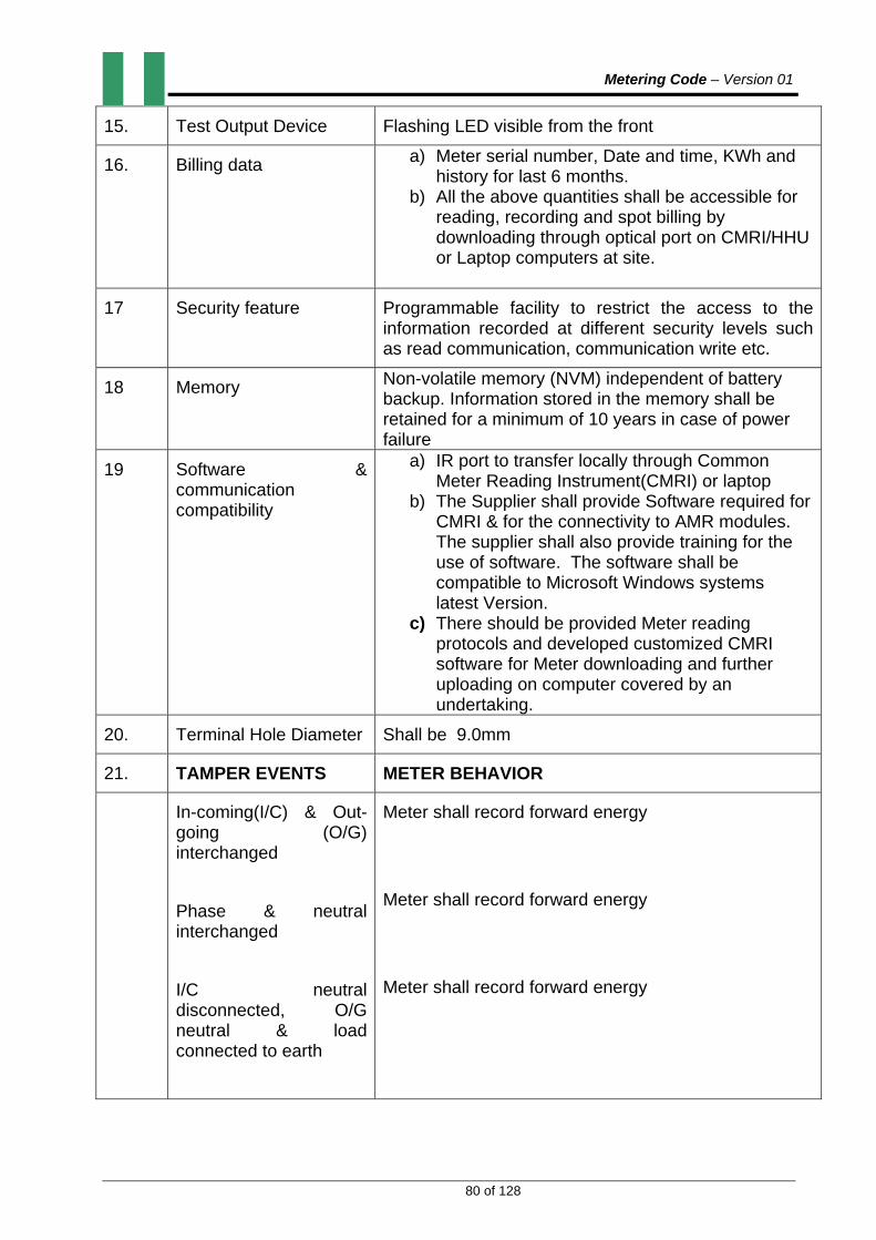
Metering Code – Version 01
80 of 128
15. Test Output Device Flashing LED visible from the front
16. Billing data a) Meter serial number, Date and time, KWh and history for last 6 months.
b) All the above quantities shall be accessible for reading, recording and spot billing by downloading through optical port on CMRI/HHU or Laptop computers at site.
17 Security feature Programmable facility to restrict the access to the information recorded at different security levels such as read communication, communication write etc.
18 Memory Non-volatile memory (NVM) independent of battery backup. Information stored in the memory shall be retained for a minimum of 10 years in case of power failure
19 Software & communication compatibility
a) IR port to transfer locally through Common Meter Reading Instrument(CMRI) or laptop
b) The Supplier shall provide Software required for CMRI & for the connectivity to AMR modules. The supplier shall also provide training for the use of software. The software shall be compatible to Microsoft Windows systems latest Version.
c) There should be provided Meter reading protocols and developed customized CMRI software for Meter downloading and further uploading on computer covered by an undertaking.
20. Terminal Hole Diameter Shall be 9.0mm
21. TAMPER EVENTS METER BEHAVIOR
In-coming(I/C) & Out-going (O/G) interchanged
Phase & neutral interchanged
I/C neutral disconnected, O/G neutral & load connected to earth
Meter shall record forward energy
Meter shall record forward energy
Meter shall record forward energy

Metering Code – Version 01
81 of 128
I/C neutral disconnected, O/G neutral connected to earth through a resistor
I/C neutral connected, O/G neutral connected to earth through a resistor
IC phase & neutral interchanged, load connected to earth
Meter shall record forward energy
Meter shall record forward energy
Meter shall record forward energy
22. Influence parameters The Meter shall work satisfactorily with guaranteed accuracy limit under the presence of following quantities as per IEC 62053-23
c) External magnetic fields d) Electromagnetic field induction e) Radio frequency interference f) Vibration etc g) Waveform 10% of H.F Fields h) D.C Immunity test
23. Display Sequence for parameters
Default display
Cumulative KWh (cumulative KWh to be displayed continuously without decimal.
On Demand Display
After pressing the push button, the following parameters shall be displayed
a) LCD test b) Date c) Real time d) Last month billing date e) Last month billing KWh reading f) Meter serial number
4.4.7. 3PHASE 4WIRE 10(100) AMPS (WHOLE CURRENT) ELECTRONIC CREDIT METER
S/NO. FUNCTION/FEATURE TECHNICAL REQUIREMENTS
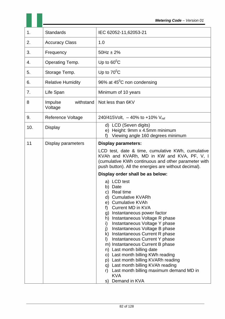
Metering Code – Version 01
82 of 128
1. Standards IEC 62052-11,62053-21
2. Accuracy Class 1.0
3. Frequency 50Hz ± 2%
4. Operating Temp. Up to 600C
5. Storage Temp. Up to 700C
6. Relative Humidity 96% at 450C non condensing
7. Life Span Minimum of 10 years
8 Impulse withstand Voltage
Not less than 6KV
9. Reference Voltage 240/415Volt, – 40% to +10% Vref
10. Display d) LCD (Seven digits) e) Height: 9mm x 4.5mm minimum f) Viewing angle 160 degrees minimum
11 Display parameters Display parameters:
LCD test, date & time, cumulative KWh, cumulative KVAh and KVARh, MD in KW and KVA, PF, V, I (cumulative KWh continuous and other parameter with push button). All the energies are without decimal).
Display order shall be as below:
a) LCD test b) Date c) Real time d) Cumulative KVARh e) Cumulative KVAh f) Current MD in KVA g) Instantaneous power factor h) Instantaneous Voltage R phase i) Instantaneous Voltage Y phase j) Instantaneous Voltage B phase k) Instantaneous Current R phase l) Instantaneous Current Y phase m) Instantaneous Current B phase n) Last month billing date o) Last month billing KWh reading p) Last month billing KVARh reading q) Last month billing KVAh reading r) Last month billing maximum demand MD in
KVA s) Demand in KVA

Metering Code – Version 01
83 of 128
t) Demand in KVA occurrence Date
12. Power factor range Zero lag – unity – zero lead
13. Burden Less than 1 watt & 2 VA/phase voltage circuit, 1 VA in current circuit.
14. Starting current 0.4% of Ib.
15. Test Output Device Flashing LED visible from the front.
16. Billing data a) Meter serial number, Date and time, KWh, KVAh, KVARh and KVA.
b) No of tamper counts, tamper occurrence with date & time, tamper restoration date & time with snap shots
c) No of tamper counts, tamper occurrence with date & time, tamper restoration date & time with snap shots
d) History of KWh, KVAh, KVARh & MD for last 6 months along with Time Of Day readings.
e) All the above parameters (namely KWh, KVAh, KVARh & KVA) are meter readings.
f) All the above quantities shall be accessible for reading, recording and spot billing by downloading through optical port IR or Laptop computers/CMRI at site.
17 MD Registration a) Meter shall store MD in every 30min period along with date and time.
b) It shall possible to reset MD automatically at the defined date(period)
18 Auto Reset of MD Auto reset date of MD shall be indicated at the time of commissioning and provision shall be made to change MD reset date through CMRI even after installation of meter on site
19 Time Of Day Metering Meter shall be capable of doing TOD Metering for KWh, KVARh, KVAh, and MD in KW and KVA for minimum of 36 days
20 Load survey 30 mins integration period, load profile of average voltage and current, KW and KVA for minimum of 36 days
21 Data reading from the meter and downloading on desktop PC
Meter data consisting of all parameters and 36 days load survey for 4 parameters shall be read by CMRI and downloaded on desktop PC
22 Security feature Programmable facility to restrict the access to the information recorded at different security levels such

Metering Code – Version 01
84 of 128
as read communication, communication write etc.
23 Diagnostic feature Self-diagnostic for time, calendar, RTC, battery with display segments and NVM
24 Memory Non-volatile memory (NVM) independent of battery backup. Information stored in the memory shall be retained for a minimum of 10 years in case of power failure
25 Software & communication compatibility
a) Optical port with RS 232/485 compatible to transfer the data locally through CMRI and remotely through modems such as mobile telephony, radio frequency, fixed line, satellite, or power line communications technology.
b) The Service Provider shall provide Software required for CMRI and IEC 62056-21 DLMS/COSEM for the connectivity to AMR/AMI modules. The MSP shall also provide training for the use of software. The software shall be compatible to Microsoft Windows systems latest Version. The software shall have polling feature with optical selection of parameters to be downloaded for AMR/AMI application.
c) Necessary provision shall be made in the software for converting all the parameters available for new and old meters if supplied earlier. Operation manual shall be in English language.
d) The meter shall have capability to store the tamper status in the memory in the form of status word. Any change in the status word (selectable basis) the meter shall generate the interrupt to initiate the communication with the AMR/AMI module through RS 232/485 port if is connected.
26. Terminal Hole Diameter Shall be 9.0mm
4.4.8. 3PH 4W CT OPERATED STATIC ENERGY METER
S/NO. FUNCTION/FEATURE TECHNICAL REQUIREMENTS
1. Standards IEC 62052-11, 62053 – 22, 23
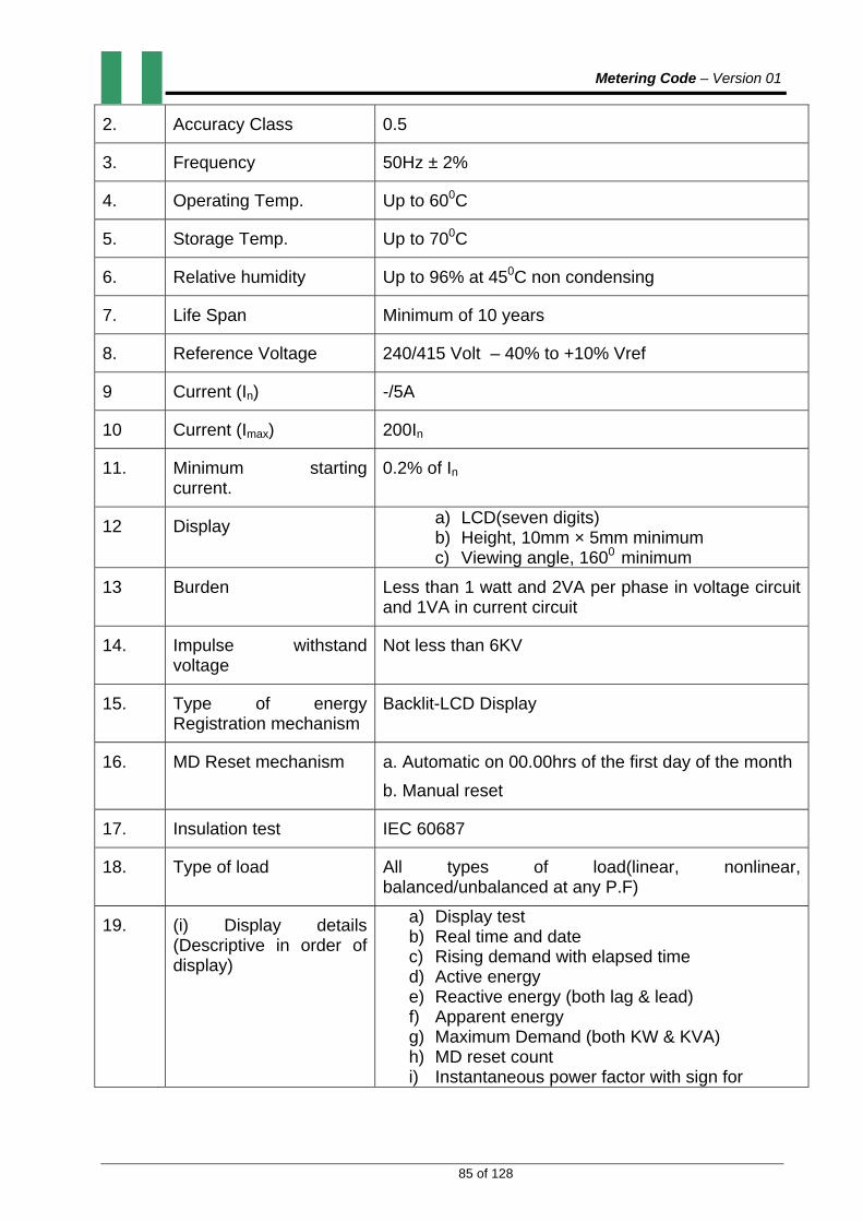
Metering Code – Version 01
85 of 128
2. Accuracy Class 0.5
3. Frequency 50Hz ± 2%
4. Operating Temp. Up to 600C
5. Storage Temp. Up to 700C
6. Relative humidity Up to 96% at 450C non condensing
7. Life Span Minimum of 10 years
8. Reference Voltage 240/415 Volt – 40% to +10% Vref
9 Current (In) -/5A
10 Current (Imax) 200In
11. Minimum starting current.
0.2% of In
12 Display a) LCD(seven digits) b) Height, 10mm × 5mm minimum c) Viewing angle, 1600 minimum
13 Burden Less than 1 watt and 2VA per phase in voltage circuit and 1VA in current circuit
14. Impulse withstand voltage
Not less than 6KV
15. Type of energy Registration mechanism
Backlit-LCD Display
16. MD Reset mechanism a. Automatic on 00.00hrs of the first day of the month
b. Manual reset
17. Insulation test IEC 60687
18. Type of load All types of load(linear, nonlinear, balanced/unbalanced at any P.F)
19. (i) Display details (Descriptive in order of display)
a) Display test b) Real time and date c) Rising demand with elapsed time d) Active energy e) Reactive energy (both lag & lead) f) Apparent energy g) Maximum Demand (both KW & KVA) h) MD reset count i) Instantaneous power factor with sign for
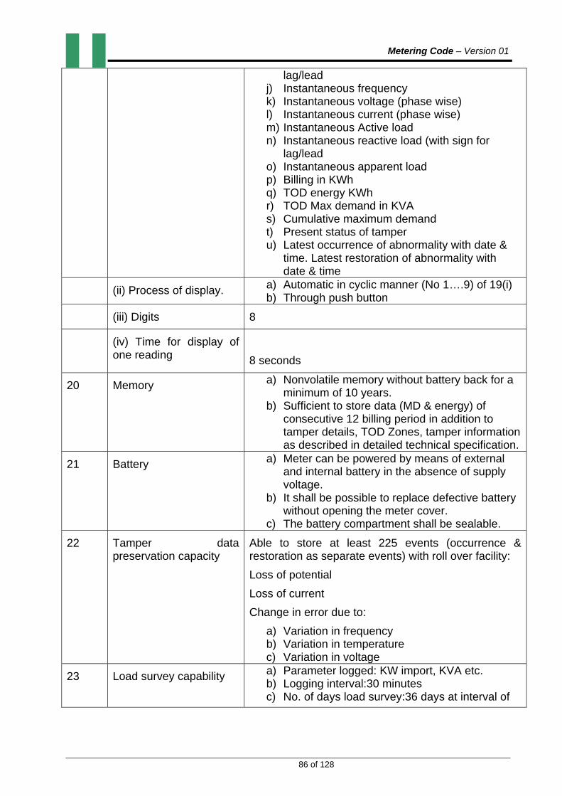
Metering Code – Version 01
86 of 128
lag/lead j) Instantaneous frequency k) Instantaneous voltage (phase wise) l) Instantaneous current (phase wise) m) Instantaneous Active load n) Instantaneous reactive load (with sign for
lag/lead o) Instantaneous apparent load p) Billing in KWh q) TOD energy KWh r) TOD Max demand in KVA s) Cumulative maximum demand t) Present status of tamper u) Latest occurrence of abnormality with date &
time. Latest restoration of abnormality with date & time
(ii) Process of display. a) Automatic in cyclic manner (No 1….9) of 19(i) b) Through push button
(iii) Digits 8
(iv) Time for display of one reading
8 seconds
20 Memory a) Nonvolatile memory without battery back for a minimum of 10 years.
b) Sufficient to store data (MD & energy) of consecutive 12 billing period in addition to tamper details, TOD Zones, tamper information as described in detailed technical specification.
21 Battery a) Meter can be powered by means of external and internal battery in the absence of supply voltage.
b) It shall be possible to replace defective battery without opening the meter cover.
c) The battery compartment shall be sealable.
22 Tamper data preservation capacity
Able to store at least 225 events (occurrence & restoration as separate events) with roll over facility:
Loss of potential
Loss of current
Change in error due to:
a) Variation in frequency b) Variation in temperature c) Variation in voltage
23 Load survey capability
a) Parameter logged: KW import, KVA etc. b) Logging interval:30 minutes c) No. of days load survey:36 days at interval of

Metering Code – Version 01
87 of 128
30 minutes
24 Earthing terminals As per IEC 60687
25 Time of day As per utility’s request
26. Capability for fraud prevention & detection
The Meter shall store in its memory, occurrence and restoration of the following tampers:
a) Missing potential b) CT short/CT Open c) Current reversal d) Current unbalance e) Current missing with date, time and also log the
events.
27. Sealing and Locking arrangement
2 sealing screws on the Meter cover and 2 sealing screws on terminal cover shall be provided. Separate sealing arrangements shall be provided for MD reset button & optical port.
28. Type of communication Data can be transferred to and from a CMRI through optical port conforming to IEC 61107 provided in front of the Meter. Also, data can be transferred through central based computer using modems such as mobile telephony, radio frequency, fixed line, satellite, or power line communications technology with IEC 62056-21 DLMS/COSEM protocol. The data element size and its overhead speed of transmission shall be less than 10 minutes.
29 Others Meter shall record energy correctly
a) In case of current reversal b) In case of neutral failure c) In case of neutral disturbance d) Meter shall record at Imax in any tamper event
due to magnetic influence
30. Real Time Clock Time drift of Real Time Clock in the Meter shall be less than ± 7 minutes per year.
4.4.8.1. The LV CT operated M.D Meter shall record active energy in forward direction even if one or more CTs are reversed. For consumer metering application, current vector direction should always be considered as positive (import) for the

Metering Code – Version 01
88 of 128
computation of three phase active energy, which shall be added to the main active energy (import) register.
4.4.8.2. The M.D Meter shall record apparent energy in forward direction even if one or more CTs are reversed. KVA shall be computed as:
KVA = √ (KW2 + KVAr2 )for lagging reactive energy and KVA = KW for leading reactive energy.
4.4.9. 3PH 4W CT/VT HIGH VOLTAGE OPERATED STATIC ENERGY METER
S/NO. FUNCTION/FEATURE TECHNICAL REQUIREMENTS
1. Standards IEC 62052-11, 62053-22&23
2. Accuracy Class 0.5
3. Frequency 50Hz ± 2%
4. Operating Temp. Up to 600C
5. Storage Temp. Up to 700C
6. Relative humidity Up to 96% at 450C non condensing
7. Life Span Minimum of 10 years
8 Current -/5A,(for 11KV) and -/1A(33KV and above)
9. Rated Voltage 63V
10 Operating voltage range (50 – 70)V
11. Minimum starting current 0.1% of Ib
12. Burden Less than 1 watt and 2VA per phase in voltage circuit and 1VA in current circuit.
13. Impulse Withstand Voltage
Not less than 6KV
14. Type of energy Registration mechanism
Back-lit LCD
15. MD Reset mechanism a) Automatic on 00.00hrs of the first day of the month
b) Manual reset
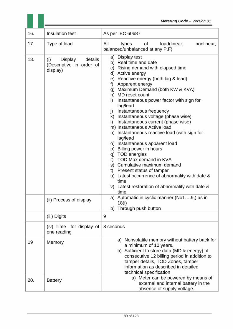
Metering Code – Version 01
89 of 128
16. Insulation test As per IEC 60687
17. Type of load All types of load(linear, nonlinear, balanced/unbalanced at any P.F)
18. (i) Display details (Descriptive in order of display)
a) Display test b) Real time and date c) Rising demand with elapsed time d) Active energy e) Reactive energy (both lag & lead) f) Apparent energy g) Maximum Demand (both KW & KVA) h) MD reset count i) Instantaneous power factor with sign for
lag/lead j) Instantaneous frequency k) Instantaneous voltage (phase wise) l) Instantaneous current (phase wise) m) Instantaneous Active load n) Instantaneous reactive load (with sign for
lag/lead o) Instantaneous apparent load p) Billing power in hours q) TOD energies r) TOD Max demand in KVA s) Cumulative maximum demand t) Present status of tamper u) Latest occurrence of abnormality with date &
time v) Latest restoration of abnormality with date &
time
(ii) Process of display a) Automatic in cyclic manner (No1….9,) as in 18(i)
b) Through push button
(iii) Digits 9
(iv) Time for display of one reading
8 seconds
19 Memory a) Nonvolatile memory without battery back for a minimum of 10 years.
b) Sufficient to store data (MD & energy) of consecutive 12 billing period in addition to tamper details, TOD Zones, tamper information as described in detailed technical specification
20. Battery a) Meter can be powered by means of external and internal battery in the absence of supply voltage.
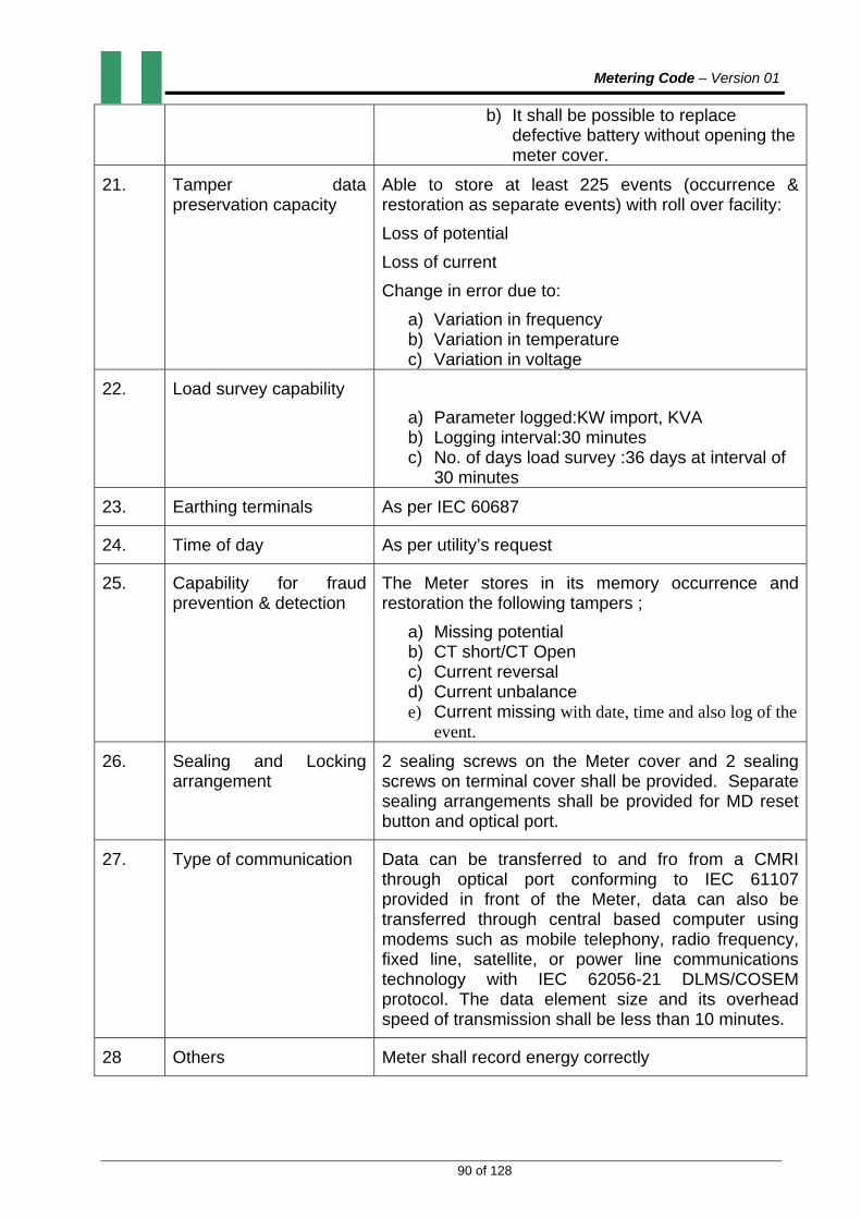
Metering Code – Version 01
90 of 128
b) It shall be possible to replace defective battery without opening the meter cover.
21. Tamper data preservation capacity
Able to store at least 225 events (occurrence & restoration as separate events) with roll over facility:
Loss of potential
Loss of current
Change in error due to:
a) Variation in frequency b) Variation in temperature c) Variation in voltage
22. Load survey capability
a) Parameter logged:KW import, KVA b) Logging interval:30 minutes c) No. of days load survey :36 days at interval of
30 minutes
23. Earthing terminals As per IEC 60687
24. Time of day As per utility’s request
25. Capability for fraud prevention & detection
The Meter stores in its memory occurrence and restoration the following tampers ;
a) Missing potential b) CT short/CT Open c) Current reversal d) Current unbalance e) Current missing with date, time and also log of the
event.
26. Sealing and Locking arrangement
2 sealing screws on the Meter cover and 2 sealing screws on terminal cover shall be provided. Separate sealing arrangements shall be provided for MD reset button and optical port.
27. Type of communication Data can be transferred to and fro from a CMRI through optical port conforming to IEC 61107 provided in front of the Meter, data can also be transferred through central based computer using modems such as mobile telephony, radio frequency, fixed line, satellite, or power line communications technology with IEC 62056-21 DLMS/COSEM protocol. The data element size and its overhead speed of transmission shall be less than 10 minutes.
28 Others Meter shall record energy correctly

Metering Code – Version 01
91 of 128
a) In case of current reversal b) In case of neutral failure c) In case of neutral disturbance d) Meter shall record at Imax in any tamper event
due to magnetic influence
28. Real time Clock Time drift of Real time clock in the Meter shall be less than ± 7 minutes per year.
4.4.9.1. The HV CT operated M.D Meter shall record active energy in forward direction even if one or more CTs are reversed. For consumer Metering application, current vector direction should always be considered as positive (import) for the computation of three phase active energy, which shall be added to the main active energy (import) register.
4.4.9.2. The M.D Meter shall record apparent energy in forward direction even if one or more CTs are reversed. KVA shall be computed as
KVA = √ (KW2 + KVAr2 ) for lagging reactive energy and KVA = KW for leading reactive energy.
4.4.10. STATIC GRID ENERGY METER (33KV and above)
S/N FUNCTION/FEATURE TECHNICAL REQUIREMENTS
1 Voltage 3x-/110/63.5V
2 Current 3x-/1A
3 Frequency 50Hz ±2%
4 System 3PH3W/3PH4W
5 Secondary voltage variation (85 – 120)V/(50 – 70)V
6 Internal battery Lithium CR2025 – 1HF or an equivalent giving a total stand-by life of 10 years (minimum)
7 Auxiliary Battery Shall be 12 d.c. supply for downloading stored data.
8 Accuracy Class 0.5S for 33KV, 0.2S for 132 and 330KV

Metering Code – Version 01
92 of 128
9 Operating Temp. Range Up to 60oC
10 Storage Temp. Range Up to 70oC
11 Relative Humidity Up to 96% at 45oC non-condensing
12 Burden 2VA/Phase in Voltage circuit and1VA/Phase in Current circuit
13 Casing material The casing shall be for wall mounting and fire retardant type of bakelite or polycarbonate
14 Screws
Current Terminals
Cable size/type
Voltage Terminals
Cable size/type
Auxiliary Terminal
Cable size/type
All screws shall be stainless steel or nickel plated brass
2 per terminal (6mm)
4mmsq/multi strand
1 per terminal (4mm)
2.5mmsq/single core
3mm
1.5mmsq/single core
15 Insulation a) 2.0KV for 1min for current
circuit b) 2.0KV for 1min for voltage
circuit c) 4.0KV for 1 min for current,
voltage, all relay contacts plus auxiliary inputs plus RS485 port together
d) 4.0KV for 1 min between all relay contacts and the auxiliary input plus communication port (RS485)
e) 4.0KV for 1min between one set of relay contacts and the
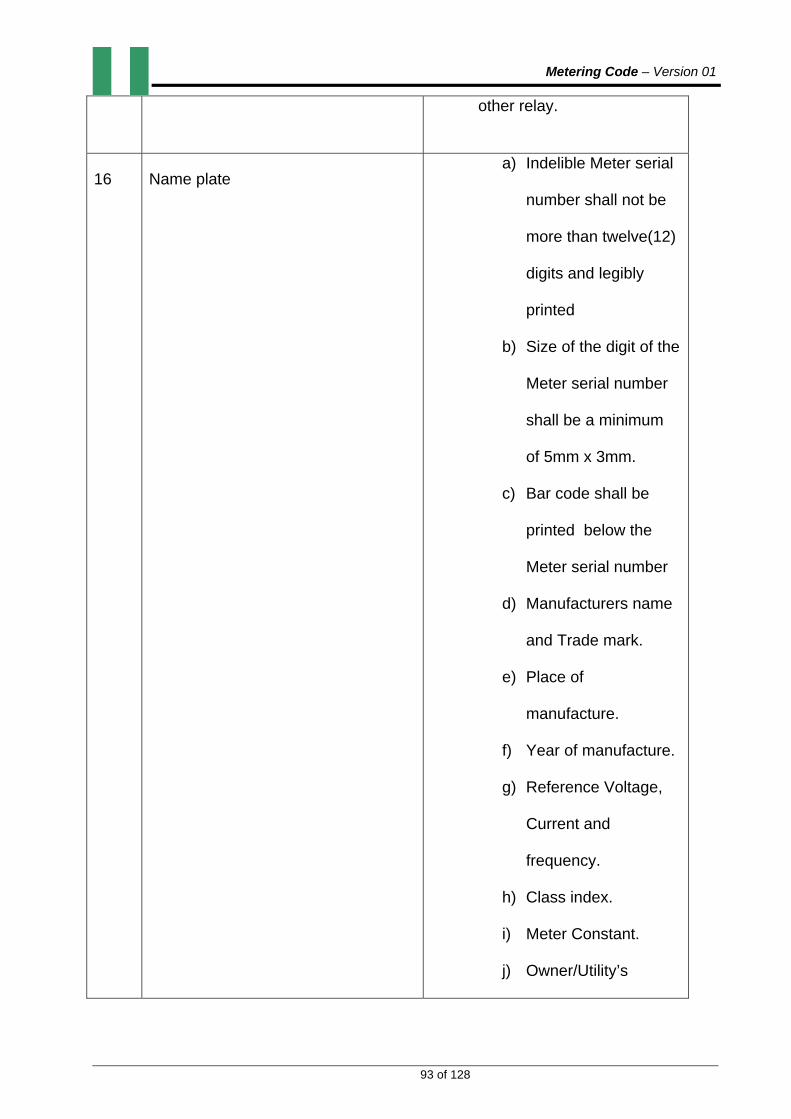
Metering Code – Version 01
93 of 128
other relay.
16 Name plate a) Indelible Meter serial
number shall not be
more than twelve(12)
digits and legibly
printed
b) Size of the digit of the
Meter serial number
shall be a minimum
of 5mm x 3mm.
c) Bar code shall be
printed below the
Meter serial number
d) Manufacturers name
and Trade mark.
e) Place of
manufacture.
f) Year of manufacture.
g) Reference Voltage,
Current and
frequency.
h) Class index.
i) Meter Constant.
j) Owner/Utility’s

Metering Code – Version 01
94 of 128
Identity
17 Measured quantity a) Import KWh b) Export KWh c) Import KVARh d) Export KVARh e) Maximum Demand in KVA f) Four Quadrant KVArh g) Load profile (180 – 450)
days
18 Tariffication a) Time of use register b) MD register c) Programmable integration
period d) Switching times e) Seasons time f) Billing dates g) End of billing dates
19 Display The display shall be capable of displaying default, customer and utility modes
20 Events Monitoring The meter shall be able to monitor the following events among others:
a) Battery failure b) Battery elapse warning c) Reverse run warning d) Over current e) Over voltage f) Phase failure g) Power factor h) Demand i) Meter communication event j) Time and date of events etc.
21 Communication a) RS485 to be fitted b) Opto port: electronic, bi-
directional c) modems such as mobile
telephony, radio frequency, fixed line, satellite, or power line communications technology.
d) Protocol: IEC 62056-21DLMS/COSEM
22 Safety Class Category – IEC61010, IEC61011 class II

Metering Code – Version 01
95 of 128
23 Real Time Clock a) Type: Capable of
synchronizing to A.C supply or to a crystal oscillator
b) Accuracy: Better than 0.5 of a second per day at 50oC
4.5. PREPAYMENT METERING SYSTEM All Prepayment Metering Installations shall be of the split type and conform to the details below. 4.5.1. KEYPAD SINGLE &THREE PHASE ELECTRICITY DISPENSER
Nominal Voltage 1Ø-240V,1-ph,2-wire system,
3Ø- 240/415, 3-ph, 4-wire system for use in balanced and unbalanced load conditions.
Operating Voltage -40% to +10% Nominal Voltage
Current Rating 5(60)A,3 X5(60)A
Frequency 50 ±2%Hz
Accuracy Class 1
Encryption Algorithm Standard Transfer Specification (STS)
Operating Temp. Up to 600C
Storage Temp. Up to 700C
Relative Humidity 96% at 450C non- condensing
Maximum KWH credit stored 99,999.9 KWh(1Ø),999,999.9KWh(3Ø)
Credit transfer number 20 Digits encryption
Protection High resistance to short circuit
Impulse withstand voltage Preferably greater than 6 KV
Insulation withstand voltage 2 KV per minute
Name plate a) Indelible Meter serial
number shall not be more
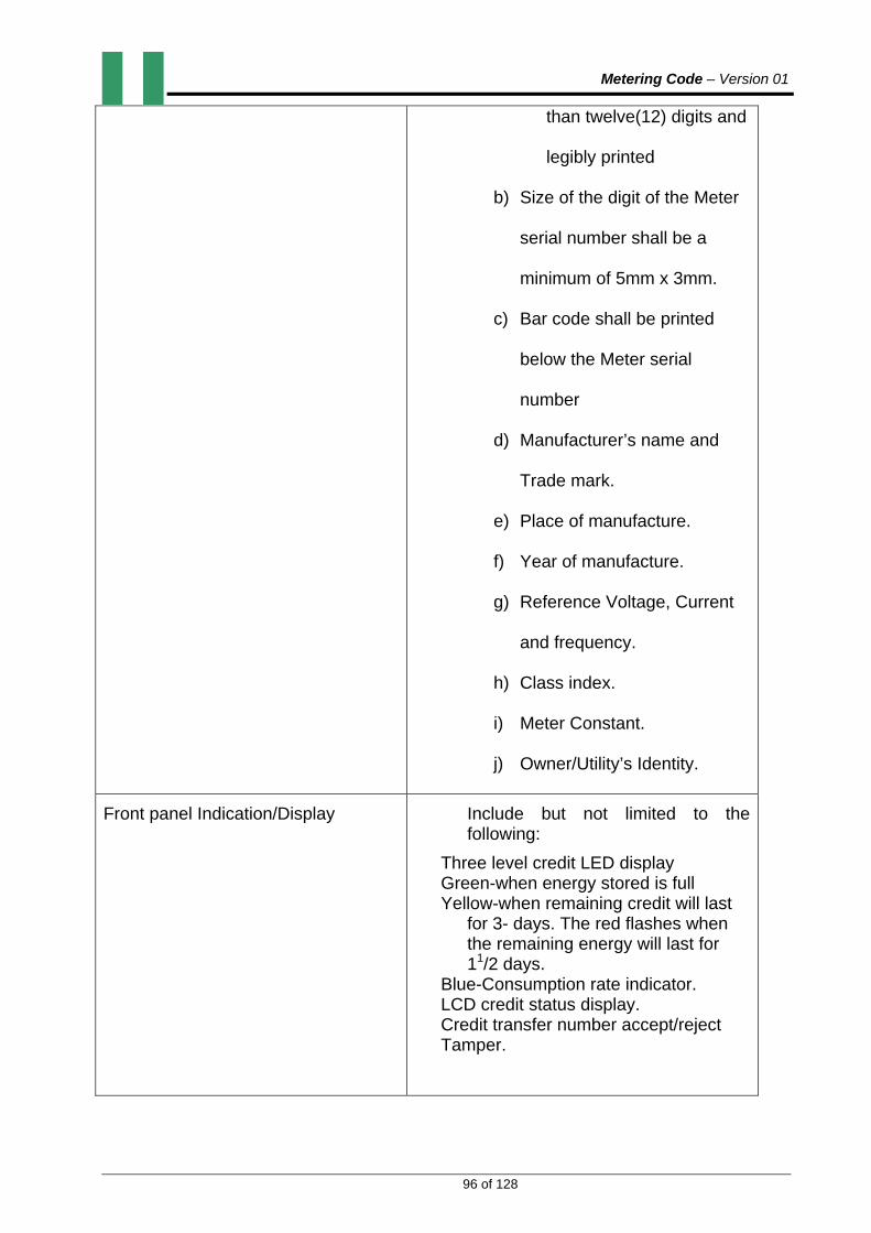
Metering Code – Version 01
96 of 128
than twelve(12) digits and
legibly printed
b) Size of the digit of the Meter
serial number shall be a
minimum of 5mm x 3mm.
c) Bar code shall be printed
below the Meter serial
number
d) Manufacturer’s name and
Trade mark.
e) Place of manufacture.
f) Year of manufacture.
g) Reference Voltage, Current
and frequency.
h) Class index.
i) Meter Constant.
j) Owner/Utility’s Identity.
Front panel Indication/Display Include but not limited to the following:
Three level credit LED display Green-when energy stored is full Yellow-when remaining credit will last
for 3- days. The red flashes when the remaining energy will last for 11/2 days.
Blue-Consumption rate indicator. LCD credit status display. Credit transfer number accept/reject Tamper.
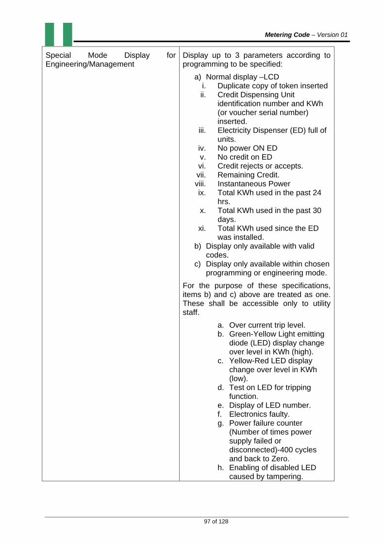
Metering Code – Version 01
97 of 128
Special Mode Display for Engineering/Management
Display up to 3 parameters according to programming to be specified:
a) Normal display –LCD i. Duplicate copy of token inserted ii. Credit Dispensing Unit
identification number and KWh (or voucher serial number) inserted.
iii. Electricity Dispenser (ED) full of units.
iv. No power ON ED v. No credit on ED vi. Credit rejects or accepts. vii. Remaining Credit. viii. Instantaneous Power ix. Total KWh used in the past 24
hrs. x. Total KWh used in the past 30
days. xi. Total KWh used since the ED
was installed. b) Display only available with valid
codes. c) Display only available within chosen
programming or engineering mode.
For the purpose of these specifications, items b) and c) above are treated as one. These shall be accessible only to utility staff.
a. Over current trip level. b. Green-Yellow Light emitting
diode (LED) display change over level in KWh (high).
c. Yellow-Red LED display change over level in KWh (low).
d. Test on LED for tripping function.
e. Display of LED number. f. Electronics faulty. g. Power failure counter
(Number of times power supply failed or disconnected)-400 cycles and back to Zero.
h. Enabling of disabled LED caused by tampering.
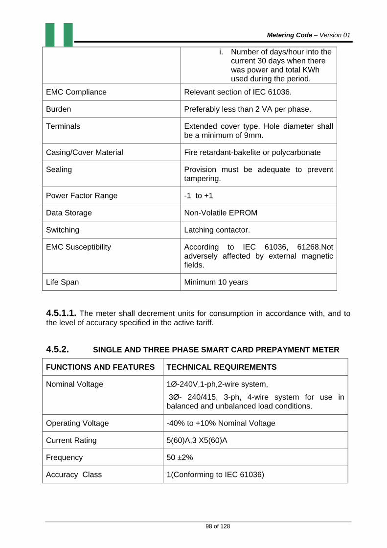
Metering Code – Version 01
98 of 128
i. Number of days/hour into the current 30 days when there was power and total KWh used during the period.
EMC Compliance Relevant section of IEC 61036.
Burden Preferably less than 2 VA per phase.
Terminals Extended cover type. Hole diameter shall be a minimum of 9mm.
Casing/Cover Material Fire retardant-bakelite or polycarbonate
Sealing Provision must be adequate to prevent tampering.
Power Factor Range -1 to +1
Data Storage Non-Volatile EPROM
Switching Latching contactor.
EMC Susceptibility According to IEC 61036, 61268.Not adversely affected by external magnetic fields.
Life Span Minimum 10 years
4.5.1.1. The meter shall decrement units for consumption in accordance with, and to the level of accuracy specified in the active tariff.
4.5.2. SINGLE AND THREE PHASE SMART CARD PREPAYMENT METER
FUNCTIONS AND FEATURES TECHNICAL REQUIREMENTS
Nominal Voltage 1Ø-240V,1-ph,2-wire system,
3Ø- 240/415, 3-ph, 4-wire system for use in balanced and unbalanced load conditions.
Operating Voltage -40% to +10% Nominal Voltage
Current Rating 5(60)A,3 X5(60)A
Frequency 50 ±2%
Accuracy Class 1(Conforming to IEC 61036)

Metering Code – Version 01
99 of 128
Operating Temp. Up to 600C
Storage Temp. Up to 700C
Relative Humidity 96% at 450C non- condensing
Maximum KWh Credit Stored 99,999.9 KWh(1Ø),999,999.9KWh(3Ø)
Credit Transfer Number 20 Digits encryption
Protection High resistance to short circuit
Impulse Withstand Voltage Preferably greater than 6 KV
Insulation Withstand Voltage 2 KV per minute
Name Plate a) Indelible Meter serial number shall
not be more than twelve(12) digits
and legibly printed.
b) Size of the digit of the Meter
serial number shall be a minimum
of 5mm x 3mm.
c) Bar code shall be printed below
the Meter serial number.
d) Manufacturer’s name and Trade
mark.
e) Place of manufacture.
f) Year of manufacture.
g) Reference Voltage, Current and
frequency.
h) Class index.
i) Meter Constant.
j) Owner/Utility’s Identity.
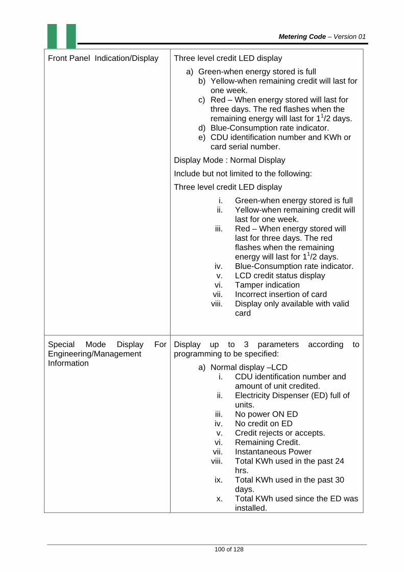
Metering Code – Version 01
100 of 128
Front Panel Indication/Display Three level credit LED display
a) Green-when energy stored is full b) Yellow-when remaining credit will last for
one week. c) Red – When energy stored will last for
three days. The red flashes when the remaining energy will last for 11/2 days.
d) Blue-Consumption rate indicator. e) CDU identification number and KWh or
card serial number.
Display Mode : Normal Display
Include but not limited to the following:
Three level credit LED display
i. Green-when energy stored is full ii. Yellow-when remaining credit will
last for one week. iii. Red – When energy stored will
last for three days. The red flashes when the remaining energy will last for 11/2 days.
iv. Blue-Consumption rate indicator. v. LCD credit status display vi. Tamper indication vii. Incorrect insertion of card viii. Display only available with valid
card
Special Mode Display For Engineering/Management Information
Display up to 3 parameters according to programming to be specified:
a) Normal display –LCD i. CDU identification number and
amount of unit credited. ii. Electricity Dispenser (ED) full of
units. iii. No power ON ED iv. No credit on ED v. Credit rejects or accepts. vi. Remaining Credit. vii. Instantaneous Power viii. Total KWh used in the past 24
hrs. ix. Total KWh used in the past 30
days. x. Total KWh used since the ED was
installed.

Metering Code – Version 01
101 of 128
xi. Display only available with valid codes.
xii. Display only available within chosen programming or engineering mode.
b) Display only available with valid codes. c) Display only available within chosen
programming or engineering mode.
For the purpose of these specifications, itemsb) and c) above are treated as one. These shall be available only to utility staff.
d) Over current trip level. e) Green-Yellow Light emitting diode (LED)
display change over level in KWh (high). f) Yellow-Red LED display change over
level in KWh (low). g) Test on LED for tripping function. h) Display of LED number. i) Electronics faulty. j) Power failure counter (Number of times
power supply failed or disconnected)-400 cycles and back to Zero.
k) Enabling of disabled LED caused by tampering.
l) Number of days/hour into the current 30 days when there was power and total KWh used during the period.
EMC Compliance Relevant section of IEC 61036.
Burden Preferably less than 2 VA per phase.
Terminals Extended cover type. Hole diameter shall be a minimum of 9mm.
Casing/Cover Materials Fire retardant-bakelite or polycarbonate
Sealing Provision must be adequate to prevent tampering.
Power Factor Range -1 to +1
Data Storage Non-Volatile EPROM
Switching Latching contactor
EMC Susceptibility According to IEC 61036, 61268.Not adversely affected by external magnetic fields.
Life Span Minimum 10 years

Metering Code – Version 01
102 of 128
4.5.3. SPLIT TYPE PREPAYMENT SINGLE & THREE PHASE DISPENSER
The technical specifications for single and three phase Electricity Dispenser shall apply except that it comprises the display unit or the consumer interface (which will be in the apartment) while the Energy Measuring and Control Unit (EMCU) shall be installed remotely from the apartment (or consumer).
4.5.3.1. Mounting shall be pole or surface (EMCU only).
4.6. AUTOMATIC METER READING SYSTEM (AMR)
4.6.1. SINGLE PHASE (DUAL PREPAYMENT AND CREDIT TYPE)
This shall have the following functions and features:
i. Remote reading ii. Remote crediting of electricity tokens iii. Voltage Rating: 240V, 2-wire iv. Current Rating: 5 (60) A v. Accuracy Class: 1 vi. Encryption Algorithm : Standard Transfer Specification (STS) vii. Frequency: 50 ±2%Hz viii. Impulse Withstand Voltage: Not Less than 6 KV ix. Burden: Less than 1 W and 2 VA in voltage circuit,
1 VA in current circuit
x. Operating Temp: Up to 600C xi. Storage Temp: Up to 700C xii. Life Span: Not less than 10 years
xiii. Front panel indications a) Three level credit LED display b) Green—when energy stored is full c) Yellow—when energy stored will last for one week d) Red—when remaining credit will last for three days. A buzzer shall
sound for one minute continuously at 30 minutes intervals when the credit remaining will last for one and a half days or less.
e) Blue—Flashes in synchronism with the rate of consumption. f) LCD credit status display g) Total KWh used to date
xiv. Display: a) Large 6 digit display. b) Digit size 9.0 X 4.5 mm
xv. Constant self-diagnostic xvi. Programmable with comprehensive tariff capability.

Metering Code – Version 01
103 of 128
xvii. Terminal: Extended cover type with external connection diagram on the inside. xviii. Terminal Hole diameter: Not less than 9.0 mm xix. Operating Voltage Range: -40% to + 10% nominal voltage xx. Switching: Latch contactor with a push button for switching on meter after it has
been credited. This is only necessary when the contactor disconnects supply to the customer due to lack of credit in the meter.
xxi. 450 days of data storage including the load profile xxii. Multi-tariff register xxiii. Anti-tampering device for meter cover. xxiv. Remote connection/disconnection. xxv. Casing material: Fire retardant –Polycarbonate
a) Communication: GSM/GPRS/PLC Modems Protocol : IEC 62056-21DLMS/COSEM xxvi. Latching contactor and front panel indication is applicable only to prepayment type.
4.6.2. THREE PHASE (PREPAYMENT/ CREDIT TYPE)
(i) The specifications are the same with (4.6.1.) above except for the
following;
a) Voltage Rating: 3 X 240/415V, 3-phase, 4-wire system for use in balanced or unbalanced load conditions
b) Current Rating: 3x 5 (60) A ii) The latching contactor and front panel indication is applicable only to
prepayment type.
4.7. DISPLAY UNIT
This is only necessary when the Meter is installed remotely in a cubicle or kiosk. The display unit shall be capable of displaying all the necessary parameters for electricity/prepayment information:
i. Total units used to date (in KWh) ii. Available credit (in KWh) iii. Present consumption rate iv. Last billing date v. Last billed amount (KWh) vi. Credit level vii. Warning on credit level viii. Other messages
4.8. LOCAL DATA CONCENTRATOR (LDC)
4.8.1.LDC shall act as a data concentrator between the meters and the Control Centre or System Master Station(SMS).It must continuously poll and store all data. The
Metering Code – Version 01
104 of 128
Concentrator is in turn polled by the Control Centre at pre-defined times, say 30 minutes (programmable) as well as on demand. 4.8.2. It must have sufficient non-volatile memory to store relevant information for a period of not less than one year. It must communicate with the meters using GSM/GPRS and maintain data integrity. The LDC shall be able to communicate with or accommodate not less than 1000 meters. Each meter shall act as a repeater. 4.9. POINT OF SALE (POS)
4.9.1. The Point Of Sale shall have a card reader attached to the Credit Dispensing Unit.(CDU).. The card reader shall be able to read or issue customer identification card. 4.9.2. The identification card shall contain meter identification and customer personal information. The issuing of credit to customer shall be made easy or quicker using the ID card. If a customer ID card is lost, it shall still be possible for the customer to purchase credit by using his name, meter serial number or account number. 4.9.3. The technical specifications and functions are the same with that of credit dispensing unit in keypad prepayment Metering System except that the application software is different. In this case, every transaction made is immediately transferred to the Control Centre. 4.9.4. Similarly, credit purchased at the POS is immediately transferred to the Control Centre to the appropriate Meter. This operation shall not take more than 5 minutes. Also the software used shall interact on a real time basis with the system data base at the Control Centre. In case of failure of communication between point of sale and Control Centre, the transaction must be logged on a local data base whereon a receipt may be issued. On restoration of the communication link, this information must be transferred to the Control Centre with confirmation. 4.9.5. The system shall have full diagnostic capabilities to ensure minimum downtime. It shall be able to detect the failure of any of the peripheral equipment.
4.9.6. RECEIPTING
Receipts issued for prepayments shall contain the following data:
i. Name of the utility company ii. Date and time of issue iii. Customer’s name iv. ID number of electricity dispenser (Meter) v. Utility’s ID number vi. Account number vii. Amount of money paid viii. Amount of electricity units paid for ix. Fixed charge x. Tariff class xi. Auxiliary charges where applicable (e.g. legacy debt recovery)

Metering Code – Version 01
105 of 128
xii. Penalty xiii. VAT xiv. Type of payment-cash/cheque xv. Customer transaction number (optional). xvi. Credit Dispensing Unit (CDU) number xvii. Operators name xviii. Message-if any xix. Contacts for complaints xx. Any other information as deemed necessary
4.9.7. CONTROL CENTRE OR SYSTEM MASTER STATION (SMS)
This is computer-based and the specifications, operation, software, 0hardware and functions are the same with those for the SMS under PPM except for the following:
(i) Control of local data concentrator (ii) Communication with local data concentrator on pre-defined time intervals
of 30 minutes (programmable) and on demand. (iii) Where the AMR is not PPM based, it can be used for automatic reading
and generation of bills. (iv) Remote connection/disconnection of customers. (v) Remote monitoring of metering installations. (vi) Remote detection of tampering with meters.
4.9.8. The system shall be capable of communicating with a variety of meters having facilities for remote operations in such a manner as to ensure adequate cyber-security and customer protection.
4.9.9. COMMUNICATIONS NETWORK Communication between the Point of Sale and the Control Centre shall be by Local Area Network or Wide Area Network. The Control Centre shall communicate with the LDC. The medium of communication shall be through mobile telephony, radio frequency, fixed line, satellite, or power line communications technology.
4.9.10. SOFTWARE PROTECTION
Adequate security shall be provided for:
(i) Token authentication
(ii) Full Audit Trail and Engineering Company.
(iii) Operator access control.
Metering Code – Version 01
106 of 128
(iv) Access control for third party vendors.
(v) Master database access.
(vi) Vend terminal control.
4.10. SMART METERING
4.10.1. SINGLE AND THREE PHASE SMART METER.
The technical specification for AMR shall apply except that they shall include:
i. Time Of Day capability
a) Meter shall be capable of doing Time of Day metering for KWh with 6 time zones programmable on-line.
b) Shall be provided with alarm to indicate tariff change.
ii. Load Profiling: Capable of recording load profiling at intervals of 30 minutes for KWh, average Voltage and Current for minimum of 72 days and transferring same on demand and at predetermined interval.
iii. Switching Circuit
a) Electrical and mechanical specifications of IEC 62055-31. Functional specifications are not applicable.
b) The breaker shall perform 3000 position changes without any maintenance.
iv. Integrated auto connect and disconnect
a) The switching equipment shall only change position as the result of a switching command.
b) It shall not be possible to manually de-activate the meter locally. c) After the breaker has been switched off due to exceeding the
threshold value, the breaker can manually be switched on. d) The meter shall provide functionality to disconnect the supply of
electricity on a preset date at a specified time. The meter shall record logging information for each disconnect.
e) It shall be possible to set electricity consumption threshold remotely. The breaker shall de-activate if the set threshold is exceeded for longer than 30 seconds.

Metering Code – Version 01
107 of 128
f) For the purposes of demand side management the integrated auto connect and disconnect shall be capable of being linked to load profiling.
v. Communications
a) The communications medium between the metering system and central station shall be through modems such as mobile telephony, radio frequency, fixed line, satellite, or power line communications technology..
b) Communication protocol shall be IEC 62056-21 DLMS/COSEM. c) The meter shall provide functionality by means of 64 bit
encryption key mechanism for authentication on the communication ports.
vi. Fraud detection and error logging a) The meter shall provide information indicating an error or fraud
attempt.
b) The error information fields shall be reset after command.
c) The meter shall issue logical error in case the end data of the requested period is prior to begin date.
d) The meter shall provide functionality to send an alarm to the central system immediately after the error that caused the alarm occurred.
e) The meter shall be capable to register meter readings and other data
and transmit same at preset intervals and on request.
f) Power quality: Capable of indicating and registering the following events: Over Current, Over Voltage, Power Factor, Phase Failure for Three Phase, Harmonics etc.
vii. Outage information shall contain the following: a) Number of short power outage (<T sec.) b) Number of outage (>T sec) for long power outage. c) Outage duration. d) Power outage on each phase shall be reconnected. e) Time stamp of the end of the outage. f) Outage information shall be provided for each phase. Only the
number of outages shall be counted. g) Meter shall re-connect to all communication channels not later than
5 minutes after power outage.

Metering Code – Version 01
108 of 128
viii. Message display a) Shall have functionality for displaying standard messages
concerning the supply of energy (Reason for disconnect, tariff charges)
b) The displayed message shall have the following characteristics. c) Can be displayed on a numerical display. d) Horizontal scrolling if the message does not fit on the display. e) A new message will override the current message and display
minimum length is eight characters. f) The message shall be shown continuously on the display until
the customer presses a button. g) A separate in-house display unit is optional.
ix. Self-diagnosis
a) The meter shall provide functionality to execute self-checks. b) The meter shall verify that it functions correctly after each
outage and each time it is connected to the grid. c) The meter shall be able to perform a consistency check on the
memory in the equipment.
4.11 CURRENT LIMITERS
The following are basic requirements:
i. Accumulation of unused energy in a storage register for later usage ii. Disconnection of supply if storage register (Stored energy) is depleted and
consumption is at a rate higher than the hourly replenishment rate, while reconnection is automatic at the next preset time period (hour)
iii. Energy allocated equally among 24 hours in a day. iv. Capable of being mounted on the pole or at customer premises (surface). v. Has an anti-tampering device for cover
4.11.1. PROGRAMMABLE FLAT RATE CURRENT LIMITER
Specific requirements for this are as follows:
FUNCTION/FEATURE TECHNICAL REQUIREMENTS
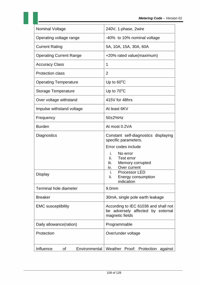
Metering Code – Version 01
109 of 128
Nominal Voltage 240V, 1-phase, 2wire
Operating voltage range -40% to 10% nominal voltage
Current Rating 5A, 10A, 15A, 30A, 60A
Operating Current Range +20% rated value(maximum)
Accuracy Class 1
Protection class 2
Operating Temperature Up to 60oC
Storage Temperature Up to 70oC
Over voltage withstand 415V for 48hrs
Impulse withstand voltage At least 6KV
Frequency 50±2%Hz
Burden At most 0.2VA
Diagnostics Constant self-diagnostics displaying specific parameters.
Error codes include
i. No error ii. Test error iii. Memory corrupted iv. Over current
Display i. Processor LED ii. Energy consumption
indication
Terminal hole diameter 9.0mm
Breaker 30mA, single pole earth leakage
EMC susceptibility According to IEC 61036 and shall not be adversely affected by external magnetic fields
Daily allowance(ration) Programmable
Protection Over/under voltage
Influence of Environmental Weather Proof: Protection against

Metering Code – Version 01
110 of 128
Condition water ingress, solar radiation, dust corrosion, rust etc.
Relative humidity 96% at 45oC non-condensing
Interruption capacity 5KA for 10ms
Casing material Non-ignitable and fire retardant – polycarbonate.
Terminal cover Extended type
4.11.2. NON-PROGRAMMABLE FLAT RATE CURRENT LIMITER
Specific requirements for this are as follows:
FUNCTION/FEATURE TECHNICAL REQUIREMENTS
Nominal Voltage 240V, 1-phase, 2wire
Operating voltage range -40% to 10% nominal voltage
Current Rating 5A, 10A, 15A, 30A, 60A
Operating Current Range +20% rated value(maximum)
Operating Temperature Up to 60oC
Storage Temperature Up to 70oC
Over voltage withstand 415V for 48hrs
Impulse withstand voltage At least 6KV
Frequency 50±2%Hz
Burden At most 0.2VA
Terminal hole diameter 9.0mm
Breaker 30mA, single pole earth leakage
EMC susceptibility According to IEC 61036 and shall not be adversely affected by external magnetic fields
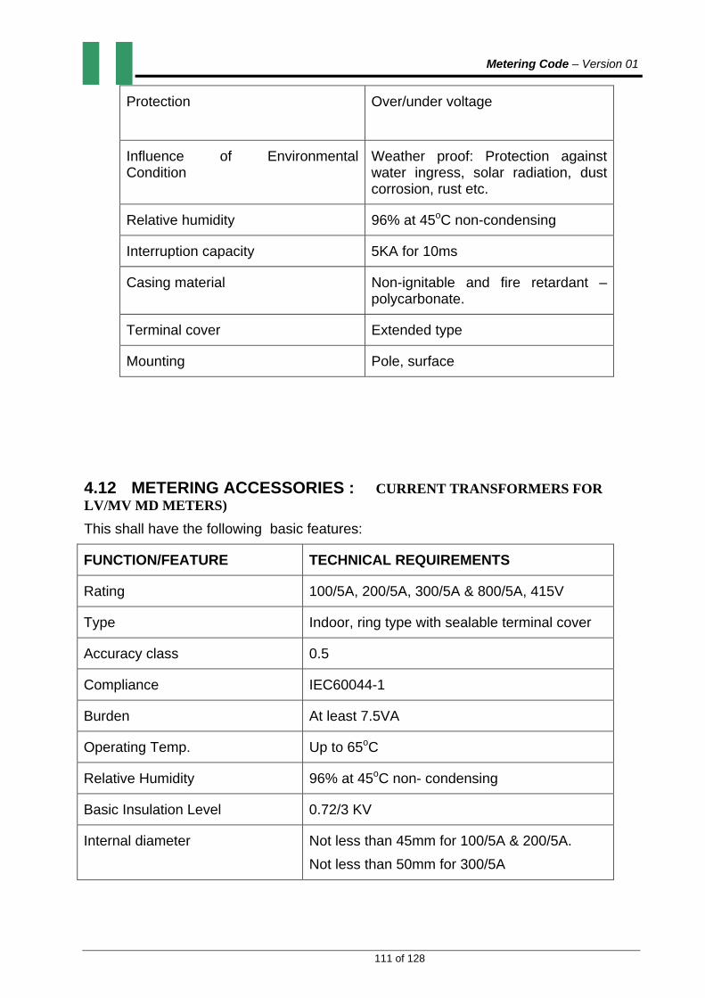
Metering Code – Version 01
111 of 128
Protection Over/under voltage
Influence of Environmental Condition
Weather proof: Protection against water ingress, solar radiation, dust corrosion, rust etc.
Relative humidity 96% at 45oC non-condensing
Interruption capacity 5KA for 10ms
Casing material Non-ignitable and fire retardant – polycarbonate.
Terminal cover Extended type
Mounting Pole, surface
4.12 METERING ACCESSORIES : CURRENT TRANSFORMERS FOR LV/MV MD METERS)
This shall have the following basic features:
FUNCTION/FEATURE TECHNICAL REQUIREMENTS
Rating 100/5A, 200/5A, 300/5A & 800/5A, 415V
Type Indoor, ring type with sealable terminal cover
Accuracy class 0.5
Compliance IEC60044-1
Burden At least 7.5VA
Operating Temp. Up to 65oC
Relative Humidity 96% at 45oC non- condensing
Basic Insulation Level 0.72/3 KV
Internal diameter Not less than 45mm for 100/5A & 200/5A.
Not less than 50mm for 300/5A

Metering Code – Version 01
112 of 128
Not less than 60mm for 500/5A & 800/5A
4.13 METERING ACCESSORIES: VOLTAGE TRANSFORMERS-
(Oil filled outdoor voltage transformer)
This shall have the following basic features:
FUNCTION/FEATURE TECHNICAL REQUIREMENTS
Voltage Rating 3x-/110V
Burden 200VA, 400VA for 11000/110V and 33000/110V respectively
Accuracy class 0.5 for 33000/110V and 0.5 for 11000/110V
Insulation class A
Insulation Level 12/28/75 for 11KV, 36/70/170 for 33KV
Operating Frequency 50±2%
Compliance With the provisions of IEC60044-2
Rated voltage Factor 1.2 continuous or 1.9 for 8hrs single pole
4.14 METERING ACCESSORIES: TEST TERMINAL BLOCKS (TTBs)
This shall have the following basic features:
FUNCTION/FEATURE TECHNICAL REQUIREMENTS
Connection Front
Cover Black bakelite or clear Poly carbonate
Voltage Terminals Together, or separate with solid links
Terminal hole diameter 9mm
Voltage Ratings 550V
Current rating 100A
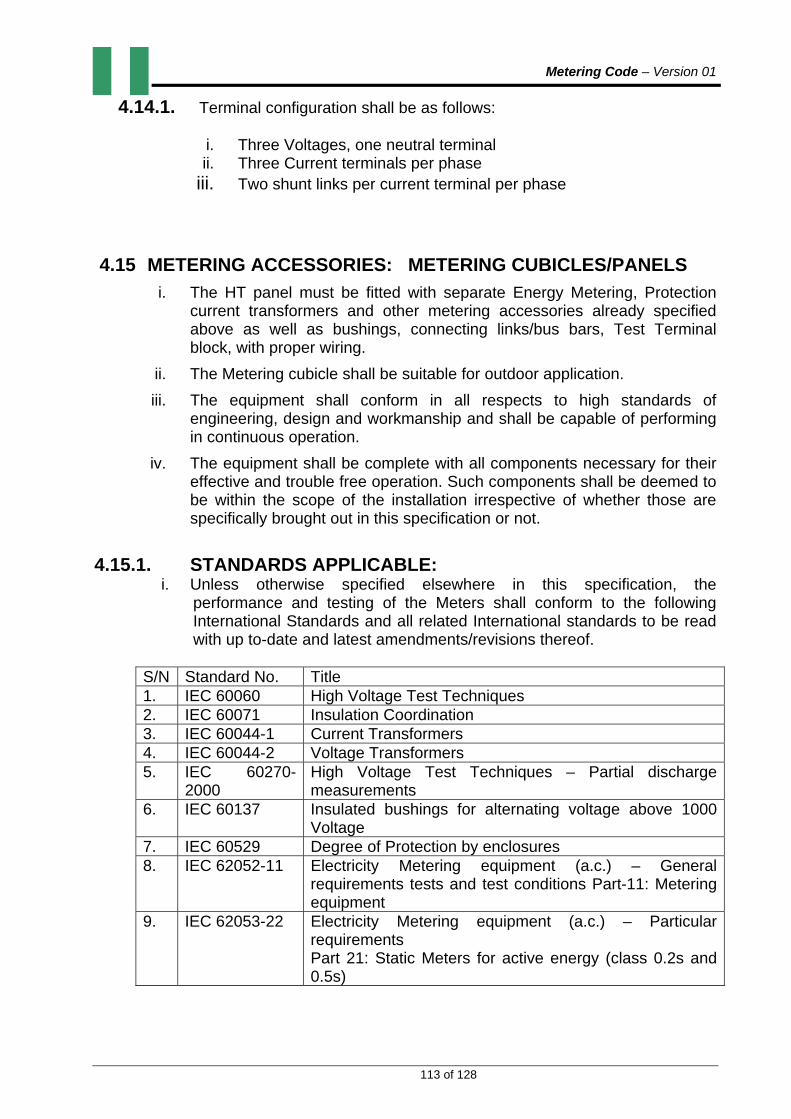
Metering Code – Version 01
113 of 128
4.14.1. Terminal configuration shall be as follows:
i. Three Voltages, one neutral terminal ii. Three Current terminals per phase
iii. Two shunt links per current terminal per phase
4.15 METERING ACCESSORIES: METERING CUBICLES/PANELS
i. The HT panel must be fitted with separate Energy Metering, Protection current transformers and other metering accessories already specified above as well as bushings, connecting links/bus bars, Test Terminal block, with proper wiring.
ii. The Metering cubicle shall be suitable for outdoor application.
iii. The equipment shall conform in all respects to high standards of engineering, design and workmanship and shall be capable of performing in continuous operation.
iv. The equipment shall be complete with all components necessary for their effective and trouble free operation. Such components shall be deemed to be within the scope of the installation irrespective of whether those are specifically brought out in this specification or not.
4.15.1. STANDARDS APPLICABLE:
i. Unless otherwise specified elsewhere in this specification, the performance and testing of the Meters shall conform to the following International Standards and all related International standards to be read with up to-date and latest amendments/revisions thereof.
S/N Standard No. Title 1. IEC 60060 High Voltage Test Techniques 2. IEC 60071 Insulation Coordination 3. IEC 60044-1 Current Transformers 4. IEC 60044-2 Voltage Transformers 5. IEC 60270-
2000 High Voltage Test Techniques – Partial discharge measurements
6. IEC 60137 Insulated bushings for alternating voltage above 1000 Voltage
7. IEC 60529 Degree of Protection by enclosures 8. IEC 62052-11 Electricity Metering equipment (a.c.) – General
requirements tests and test conditions Part-11: Metering equipment
9. IEC 62053-22 Electricity Metering equipment (a.c.) – Particular requirements Part 21: Static Meters for active energy (class 0.2s and 0.5s)

Metering Code – Version 01
114 of 128
ii. Metering Cubicle matching with requirements of other national or
international standards, which ensure equal or better performance than the standards mentioned above, shall also be applicable. When the equipment conforms to standards other than those specified, salient points of difference between standards adopted and the standards specified in this specification shall be clearly brought out and a copy of such standards in English Language shall be made available on request.
4.15.2 SERVICE CONDITIONS The equipment shall be suitable for satisfactory continuous operation under the following tropical conditions:
a) Location Anywhere in Nigeria
b) Maximum ambient air temperature 600C
b) Minimum ambient temperature. 100C c) Maximum relative humidity. 96%. d) Minimum relative humidity 10%. e) Maximum Height above mean sea level Up to 1000 metres.
4.15.3. GENERAL TECHNICAL REQUIREMENTS FOR CUBICLE : The metering cubicle shall be installed electrically in between the incoming supply point and the step down transformer of consumer’s installation. The metering cubicle shall be provided with the following components suitably mounted:
(i) 3nos. 11KV / 33KV Class 0.5 current transformers (CTs) as per the specification
(ii) 3nos. 11KV / 33KV Class 0.5 voltage transformers (VTs) as per the specification
(iii) 1no. Test Terminal Block with transparent extended cover.
(iv) 1no. Three phase four wire HT energy Meter as per the specification.
(v) 1no. space heater.
(vi) Tinned copper bus bars/connecting links totally covered by resin castings.
(vii) Secondary wires from the terminals of CTs and VTs in the CT/VT compartment shall be covered by resin cast blocks and the secondary wires shall be brought in the metering compartment through rubber bushing and shall be left open duly crimped with suitable pin type copper lugs.
(viii) Mounting plate for resin cast bushings. Bushings shall have
suitable arrangement to receive cable terminations for incoming and outgoing cables.
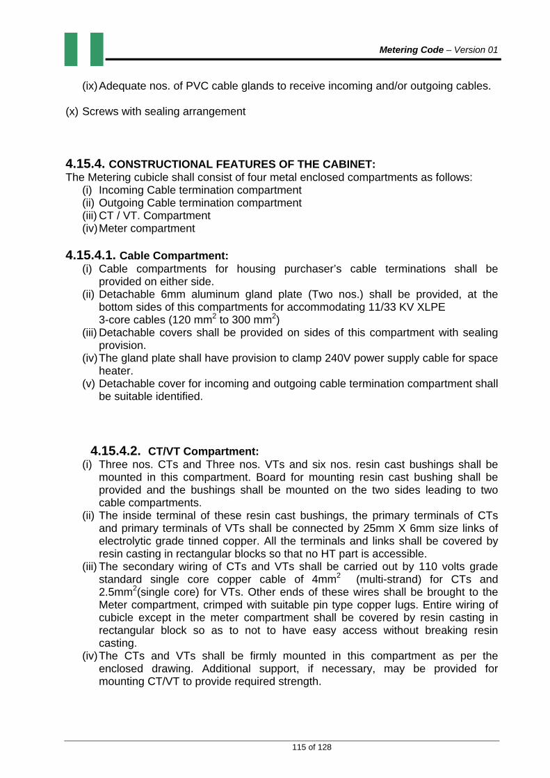
Metering Code – Version 01
115 of 128
(ix) Adequate nos. of PVC cable glands to receive incoming and/or outgoing cables.
(x) Screws with sealing arrangement
4.15.4. CONSTRUCTIONAL FEATURES OF THE CABINET: The Metering cubicle shall consist of four metal enclosed compartments as follows:
(i) Incoming Cable termination compartment (ii) Outgoing Cable termination compartment (iii) CT / VT. Compartment (iv) Meter compartment
4.15.4.1. Cable Compartment:
(i) Cable compartments for housing purchaser’s cable terminations shall be provided on either side.
(ii) Detachable 6mm aluminum gland plate (Two nos.) shall be provided, at the bottom sides of this compartments for accommodating 11/33 KV XLPE 3-core cables (120 mm2 to 300 mm2)
(iii) Detachable covers shall be provided on sides of this compartment with sealing provision.
(iv) The gland plate shall have provision to clamp 240V power supply cable for space heater.
(v) Detachable cover for incoming and outgoing cable termination compartment shall be suitable identified.
4.15.4.2. CT/VT Compartment:
(i) Three nos. CTs and Three nos. VTs and six nos. resin cast bushings shall be mounted in this compartment. Board for mounting resin cast bushing shall be provided and the bushings shall be mounted on the two sides leading to two cable compartments.
(ii) The inside terminal of these resin cast bushings, the primary terminals of CTs and primary terminals of VTs shall be connected by 25mm X 6mm size links of electrolytic grade tinned copper. All the terminals and links shall be covered by resin casting in rectangular blocks so that no HT part is accessible.
(iii) The secondary wiring of CTs and VTs shall be carried out by 110 volts grade standard single core copper cable of 4mm2 (multi-strand) for CTs and 2.5mm2(single core) for VTs. Other ends of these wires shall be brought to the Meter compartment, crimped with suitable pin type copper lugs. Entire wiring of cubicle except in the meter compartment shall be covered by resin casting in rectangular block so as to not to have easy access without breaking resin casting.
(iv) The CTs and VTs shall be firmly mounted in this compartment as per the enclosed drawing. Additional support, if necessary, may be provided for mounting CT/VT to provide required strength.
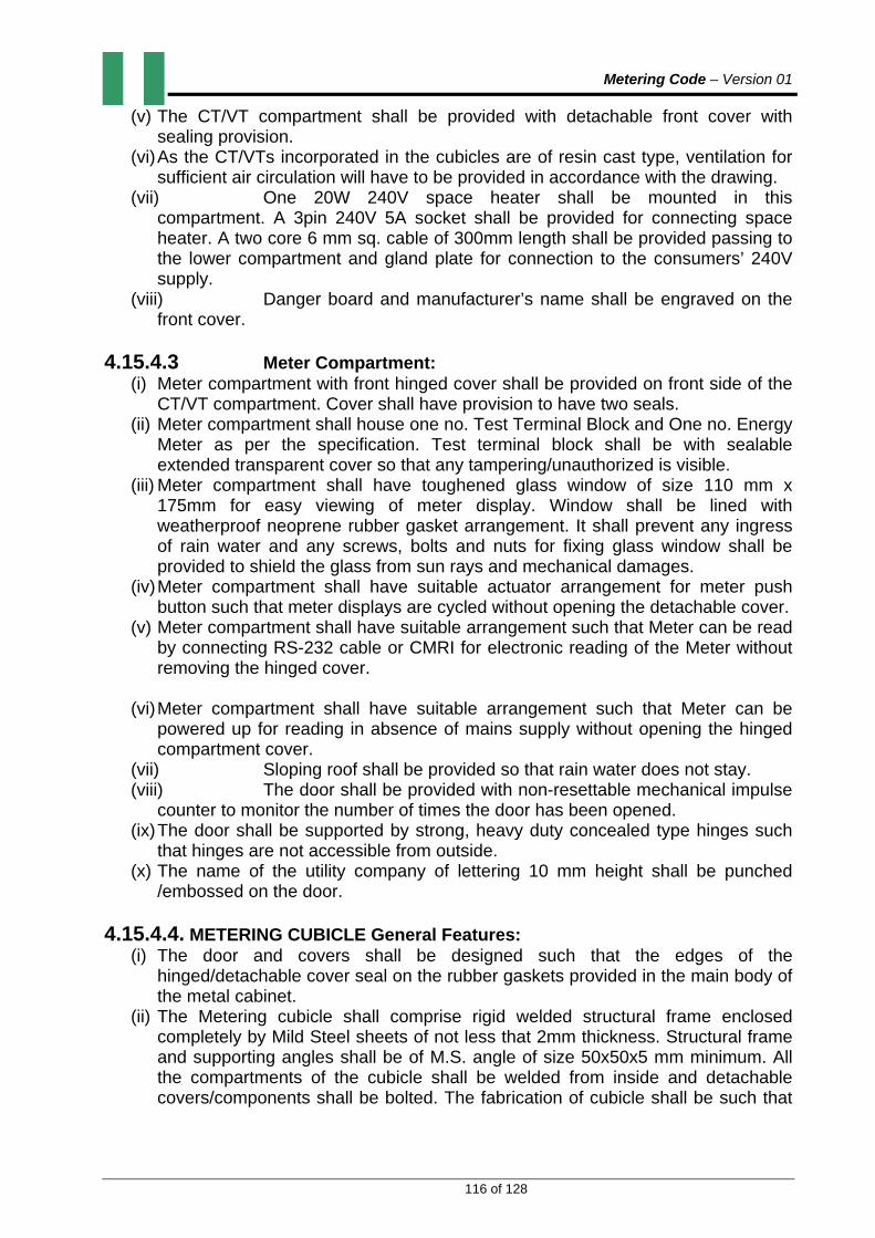
Metering Code – Version 01
116 of 128
(v) The CT/VT compartment shall be provided with detachable front cover with sealing provision.
(vi) As the CT/VTs incorporated in the cubicles are of resin cast type, ventilation for sufficient air circulation will have to be provided in accordance with the drawing.
(vii) One 20W 240V space heater shall be mounted in this compartment. A 3pin 240V 5A socket shall be provided for connecting space heater. A two core 6 mm sq. cable of 300mm length shall be provided passing to the lower compartment and gland plate for connection to the consumers’ 240V supply.
(viii) Danger board and manufacturer’s name shall be engraved on the front cover.
4.15.4.3 Meter Compartment:
(i) Meter compartment with front hinged cover shall be provided on front side of the CT/VT compartment. Cover shall have provision to have two seals.
(ii) Meter compartment shall house one no. Test Terminal Block and One no. Energy Meter as per the specification. Test terminal block shall be with sealable extended transparent cover so that any tampering/unauthorized is visible.
(iii) Meter compartment shall have toughened glass window of size 110 mm x 175mm for easy viewing of meter display. Window shall be lined with weatherproof neoprene rubber gasket arrangement. It shall prevent any ingress of rain water and any screws, bolts and nuts for fixing glass window shall be provided to shield the glass from sun rays and mechanical damages.
(iv) Meter compartment shall have suitable actuator arrangement for meter push button such that meter displays are cycled without opening the detachable cover.
(v) Meter compartment shall have suitable arrangement such that Meter can be read by connecting RS-232 cable or CMRI for electronic reading of the Meter without removing the hinged cover.
(vi) Meter compartment shall have suitable arrangement such that Meter can be
powered up for reading in absence of mains supply without opening the hinged compartment cover.
(vii) Sloping roof shall be provided so that rain water does not stay. (viii) The door shall be provided with non-resettable mechanical impulse
counter to monitor the number of times the door has been opened. (ix) The door shall be supported by strong, heavy duty concealed type hinges such
that hinges are not accessible from outside. (x) The name of the utility company of lettering 10 mm height shall be punched
/embossed on the door.
4.15.4.4. METERING CUBICLE General Features: (i) The door and covers shall be designed such that the edges of the
hinged/detachable cover seal on the rubber gaskets provided in the main body of the metal cabinet.
(ii) The Metering cubicle shall comprise rigid welded structural frame enclosed completely by Mild Steel sheets of not less that 2mm thickness. Structural frame and supporting angles shall be of M.S. angle of size 50x50x5 mm minimum. All the compartments of the cubicle shall be welded from inside and detachable covers/components shall be bolted. The fabrication of cubicle shall be such that

Metering Code – Version 01
117 of 128
there is no ingress of water. Air vents shall be provided on the panel sides for the panel ventilation in a manner as to prevent rain water ingress.
(iii) All doors and removable covers shall be gasketed all around with neoprene rubber gasket and the Metering cubicle shall meet the requirements of IP-55 protection as per IEC-60529, if the air vents are closed.
(iv) The Metering cubicle shall be mounted on concrete plinth of 300mm height. Legs shall be of size 75mm x 75mm x 5mm. A bottom frame of M.S. angles as shown in the drawings shall be provided, duly welded for mounting the cubicle on the plinth.
(v) Four lifting hooks of suitable size shall be provided at the top for lifting the cubicle.
(vi) The Metering cubicle shall be painted after proper cleaning as follows and the painting performance should be guaranteed for a period of not less than 5 years:
S/No. Paint Type No. of coats
Total Dry film thickness (min.)
1. Thermo-setting paint. 01
01
20 microns
60 microns
2. Liquid paint
a) Zinc chromate
(primer)
b) Polyurethene
(Finish coat)
01
02
30 microns
25 microns each.
.
4.15.4.5. METERING CUBICLE EARTHING: (i) Five independent Galvanized Iron bolts of at least M10 size shall be provided on
sides so that the inside and outside earthing can be done. It shall be firmly welded to the sides.
(ii) An earthing bus of copper strip of size 25 x 3 mm shall be provided and extended throughout the length of the Metering cubicle. It shall be bolted/brazed to the framework at two points. VT earthing may be made at two locations by 25 x 3 mm copper strips.
(iii) All non-current carrying metal work of the switchboard shall be effectively bonded to the earth bus.
(iv) Hinged door shall be earthed through flexible earthing braid.
4.15.4.6. METERING CUBICLE CABLE GLANDS:

Metering Code – Version 01
118 of 128
(i) The size of 11KV/33KV power cable glands being arranged by the purchaser for incoming and or outgoing supply shall be 120 mm2 to 300 mm2.
(ii) The bushings shall be suitable for double bolt connection of H.T. cable lug.
(iii) Two sets of one plain washer and one cup washer and two nuts and one bolt shall be provided for the incoming/outgoing cable connections.
(iv) There shall also include necessary numbers of heavy duty PVC cable glands for terminating 11KV / 33KV power cables.
4.16. METERING CUBICLES/PANELS ELECTRICAL EQUIPMENT: INSTRUMENT TRANSFORMERS 4.16.1 General Requirements of Electrical Equipment are mentioned as under:
(i) The Current Transformers and Voltage transformers shall conform to the requirements stipulated in relevant applicable standards.
(ii) The CTs and VTs shall be of resin cast type (Insulation Class “E”) and shall be able to withstand the thermal and mechanical stresses resulting from the maximum short circuit and momentary current ratings specified. These shall be completely encapsulated.
(iii) The resin used for manufacture of CT/VT and bushings shall be of reputed make and resin casting shall be carried out under vacuum and hot setting process only. Cold setting resin may be used for casting over complete inside wiring, connecting strip on HV side.
(iv) Instrument transformer shall have polarity marks indelibly marked on each transformer and at the associated terminal block.
(v) Each CT/VT shall be of the single phase type. (vi) Core lamination shall be of high grade steel or other equivalent alloy. (vii) Name plates showing particular connection diagram shall be
provided. They shall be made of non-corrosive material, shall be indelibly punched or marked and shall be firmly fixed on to body of instrument transformer.
(viii) CTs and VTs shall be suitable for mounting on the cubicle. 4.16.2. METERING CUBICLE GENERAL SYSTEM AND PHYSICAL PARAMETERS 1. Rated Voltage 11 KV 33 KV 2. HT System Voltage 12 KV 36 KV 3. Short Circuit withstand current and duration (kA rms 1 sec) for 100/5A 13.1 KV 26.2 KV for 25/5A 6.7 KV 13.1 KV for 10/5A 3.0 KV 6.7 KV for 5/5 A 3.0 KV 3.0 KV
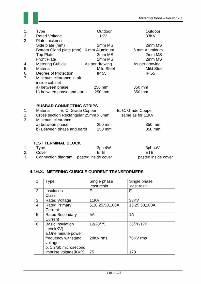
Metering Code – Version 01
119 of 128
1. Type Outdoor Outdoor 2. Rated Voltage 11KV 33KV 3. Plate thickness Side plate (mm) 2mm MS 2mm MS Bottom Gland plate (mm) 6 mm Aluminum 6 mm Aluminum Top Plate 2mm MS 2mm MS Front Plate 2mm MS 2mm MS 4. Metering Cubicle As per drawing As per drawing 5. Material Mild Steel Mild Steel 6. Degree of Protection IP 55 IP 55 7. Minimum clearance in air inside cabinet a) between phase 250 mm 350 mm b) between phase and earth 250 mm 350 mm BUSBAR CONNECTING STRIPS 1. Material E. C. Grade Copper E. C. Grade Copper 2. Cross section Rectangular 25mm x 6mm same as for 11KV 3. Minimum clearance a) between phase 250 mm 350 mm b) Between phase and earth 250 mm 350 mm TEST TERMINAL BLOCK 1. Type 3ph 4W 3ph 4W 2. Cover ETB ETB 3. Connection diagram pasted inside cover pasted inside cover 4.16.3. METERING CUBICLE CURRENT TRANSFORMERS
1 Type Single phase cast resin
Single phase cast resin
2 Insulation Class
E E
3 Rated Voltage 11KV 33KV 4 Rated Primary
Current 5,10,25,50,100A 15,25,50,100A
5 Rated Secondary Current
5A 1A
6 Basic Insulation Level(KV) a.One minute power frequency withstand voltage b. 1.2/50 microsecond impulse voltage(KVP)
12/28/75 28KV rms 75
36/70/170 70KV rms 170

Metering Code – Version 01
120 of 128
7 Rated continuous thermal current (Imax=200%)
2 X rated primary current
2 X rated primary current
8 Burden(VA) Not more than 10 Not more than 10 9 Accuracy Class 0.5 0.5 10 Instr. Sec. Factor 5 or less 5 or less 11 Core details Single core Single core 12 Short withstand
current and duration(KA rms/sec 100/5A 50/5A 25/5A 10/5A 5/5A
13.1KA 6.7KA 6.7KA 3.0KA 3.0KA
26.2KA 13.1KA 13.1KA 6.7KA 3.0KA
13 Rated Dynamic Withstand current KVP
2.5 X STC 2.5 X STC
14 Applicable Standard IEC60044-1 IEC60044-1 4.16.4. METERING CUBICLE VOLTAGE TRANSFORMERS
1 Type Single phase cast resin
Single phase cast resin
2 Insulation Class
E E
3 Ratio Tap Single ratio Single ratio 4 Rated Primary
Voltage 11KV√3 33KV√3
5 Rated Secondary Voltage
110V/√3 110V/√3
6 Basic Insulation Level(KV) a.One minute power frequency withstand voltage b. 1.2/50 microsecond impulse voltage(KVP)
12/28/75 28KV rms 75
36/70/170 70KV rms 170

Metering Code – Version 01
121 of 128
7 Burden(VA) Not less than 10 Not less than 10 8 Accuracy Class 0.5 0.5 9 Instr. Sec. Factor 5 or less 5 or less 10 Core details Single core Single core 11 Ratio 11KV/√3/110/√3 33KV/√3/110/√3 12 Applicable Standard IEC60044-2 IEC60044-2
4.16.5. METERING CUBICLE BUSHINGS
(i) Bushing shall conform to the requirements stipulated in relevant applicable standards.
(ii) A total of Epoxy moulded bushing shall be provided for cable termination and provide connection through the Current and Voltage Transformers.
(iii) Connecting rod will be part of the bushings. 4.16.6. METERING CUBICLE TEST TERMINAL BLOCKS
(i) One no. of 3 phase 4 wire type Test Terminal block shall be provided in each Metering cubicle.
(ii) Test terminal block shall be provided with extended transparent terminal cover. (iii) Connection diagram shall be visible and pasted inside the transparent cover. (iv) Wiring to the test terminal block shall be properly marked through ferrules.
4.16.7. METERING CUBICLE ENERGY METER Each metering cubicle shall be provided with Class 0.5s accuracy CT/VT operated static 110V three vector meters for tariff purpose and as required.
4.17. LT MD METERING PANELS
Type Outdoor
Dimension Spacious enough to accommodate meter, CTs, test terminal block and cablings.
Material Mild steel (or equivalent) of not less than 2mm thickness.
Rated Voltage 415Volt
Panel front Cover Hinged lockable door with 2 keys and 2 sealing

Metering Code – Version 01
122 of 128
provisions.
Glass Window There shall be a window on the panel door with toughened glass of 110mm x 75mm minimum dimension for easy viewing of Meter display. The window is also to be lined with weatherproof neoprene rubber gasket arrangement to prevent rain water ingress.
Rain protection The panel top is to be sloppy to prevent rain water ingress
Sealable optical port window A window for RS 232/485 port to be provided on the front cover/door for electronic reading of the Meter with Hand Held Unit without the need for opening the hinged door.
Anti- corrosion protection The panel shall have adequate protective coating using strong anti-corrosion material.
Power-up window There shall be provision on the panel door for powering the Meter up for reading during power failure without the need for opening the door.
Panel earthing Grounding bolts for earthing the panel with minimum of 4mm2 stranded copper wires be provided on the panel side.
Hinged door earthing The door is to be earthed through flexible braid.
Cable entry and exit holes 8nos holes of 600mm2 to be fitted with PVC cable glands to be provided on the panel bottom for power cable entry and exit.
Mounting holes 4nos mounting holes of 8mm minimum diameter to be provided on the panel back for mounting the panel on to the concrete wall. The 2 upper mounting holes shall be so bored as to enable the slot-hanging of the panel with mounting self –expanding screws.
Panel ventilation Air vents shall be provided on the panel sides for the panel ventilation in a manner as to prevent rain water ingress.
Cable clearance There shall be a minimum clearance between power cables within the panel enough to prevent any electrical short circuit between

Metering Code – Version 01
123 of 128
phases of supply
Degree of protection As applicable to switchgears operating on 415
4.18. TECHNICAL SPECIFICATION FOR MINIATURE CIRCUIT BREAKER (MCB) SINGLE & THREE PHASE
4.18.1. BASIC REQUIREMENT
The Miniature Circuit Breaker shall be used in place of service cut-outs to provide over- current and short circuit protection in all single and three phase residential premises.It shall be a compact electromechanical device for making, breaking and disconnecting a circuit in normal conditions as well as in abnormal conditions such as those of over current and short circuit.
4.18.2. The Miniature circuit breaker shall be of wire-in, wire-out type basically comprising the following features;
(i) Independent Manually operated latched switching mechanism with trip free release
(ii) Arc-quenching chamber
(iii) Instantaneous short circuit protection
(iv) Safe disconnection of load from source
4.18.3. The Single Phase Miniature circuit Breaker shall be of Single pole type suitable for operating on 240v supply and Three Phase Miniature circuit breaker shall be of three pole type suitable for operating on 415v supply. The MCB shall be suitable for panel / surface mounting with screws as necessary also shall be provided with the MCB.
4.18.4. GENERAL PROPERTIES The MCBs shall have the following properties:
S/N PARAMETER TECHNICAL REQUIREMENT
1 Rated Current 1n = 30A, 45A, 60A
2 Rated Voltage Vn = 240v for single phase (single pole), 415V for three phase (three pole)
3 System highest voltage 3ph and neutral 415/240v+10%Vn
4 System Frequency 50Hz

Metering Code – Version 01
124 of 128
5 System fault current rating 25KA (max.)
6 Maximum ambient temperature 40°c
7 Relative humidity 96% Non-Condensing
8 Environmental Condition Humid tropical climate
9 Standard IEC 60898-1
10 Rated Impulse Withstand Voltage1.2/50us
6.OkV peak
11 Clearance between open contacts 13mm(min)
12 Overload tripping Current 1.2In
13 Instantaneous tripping Between 10 and 12In
14 No of poles Single pole / Three pole
15 Terminal Holes Adequate to accommodate 16mm2 service cable
16 Operational Performance Capability
10,000 Nos. of operating cycles
5. APPENDIX E -GMC METERING CHARACTERISTICS: CLASSIFICATION OF CONNECTION POINTS AND LOCATION OF METERING SYSTEMS
5.1. GENERAL
5.1.1. This Section depicts, in the form of diagrams, the classification of types of connection points and the associated installation of Main and Check Metering Systems as specified in Sections 2.1and 2.2 of the GMC. Fig. 1a shows Types 1, 2, and 3 while Fig 1b shows Types 4, 5, and 6 with their locations of Main, Redundant Check, and Verification Check Metering Systems. Fig 2 shows the relative locations of Main and Check Meters as stipulated.
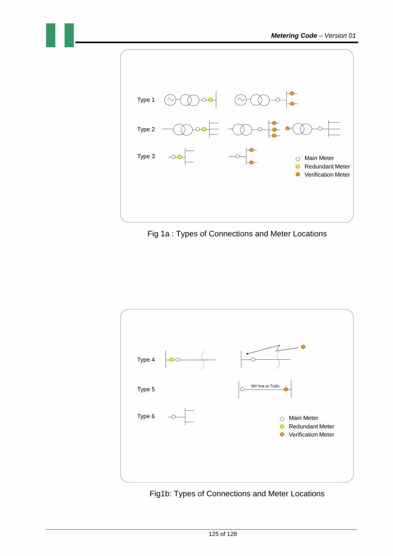
Metering Code – Version 01
125 of 128
Type 1
Type 2
Type 3 Main Meter
Redundant MeterVerification Meter
Fig 1a : Types of Connections and Meter Locations
Type 4
Type 5
Type 6 Main Meter
Redundant MeterVerification Meter
MV line or Trafo
Fig1b: Types of Connections and Meter Locations
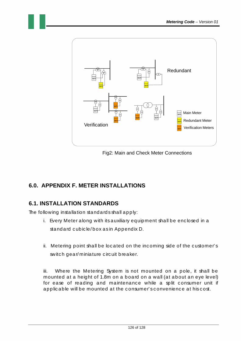
Metering Code – Version 01
126 of 128
Wh
Wh
Wh
Wh
Wh
Wh
Wh
Wh
Wh
Wh
WhWh
Main Meter
Redundant Meter
Verification Meters
Redundant
Verification
Fig2: Main and Check Meter Connections
6.0. APPENDIX F. METER INSTALLATIONS
6.1. INSTALLATION STANDARDS
The following installation standards shall apply:
i. Every Meter along with its auxiliary equipment shall be enclosed in a
standard cubicle/box as in Appendix D.
ii. Metering point shall be located on the incoming side of the customer’s
switch gear/miniature circuit breaker.
iii. Where the Metering System is not mounted on a pole, it shall be mounted at a height of 1.8m on a board on a wall (at about an eye level) for ease of reading and maintenance while a split consumer unit if applicable will be mounted at the consumer’s convenience at his cost.

Metering Code – Version 01
127 of 128
iv. The incoming service cable to the meter shall be visually traceable.
v. The size of CT secondary cables shall be 4mm2 (standard) for LV
installation and 6mm2 for H.T installation. V.T cable size shall be 2.5mm2.
vi. All VT/CT secondary cables shall be numbered and ferruled for easy
identification.
vii. The size of the neutral cable shall be the same as the size of phase
cables.
viii. Correct connection must be ensured with the right polarity, phase
association and phase sequence.
viiii. Joints in CT and VT cables shall be avoided.
x. All CT and VT cable shall be dipped/tied properly.
xi. In the case of outdoor CT and VT, the meter shall be located as close
as possible to the instrument transformers.
xii. The class of the CT shall not be inferior to the associated meter.
xiii. All components of the metering system shall be sealed as specified in
Appendix C.
6.2. INSTALLATION ACCESSORIES
6.2.1. GENERAL: The installation accessories for servicing comprise meter board for wall mounted meters, miniature circuit breaker, service wires or cables of adequate size and associated flexible piping to prevent meter bypass, and overhead or underground line materials of suitable rating for load connection within 50 meters of the public supply. The mains supply is protected using adequately rated fuses.

Metering Code – Version 01
128 of 128
6.2.2. The responsibility for bearing the cost of the installation accessories and any line extension to the meter installation beyond 50m shall be as approved by NERC.