Metaloflex Metal Layer Cylinder-Head Gaskets. The Future is in the
20
Metaloflex ® Metal Layer Cylinder-Head Gaskets. The Future is in the Head.
Transcript of Metaloflex Metal Layer Cylinder-Head Gaskets. The Future is in the

Metaloflex® Metal Layer Cylinder-Head Gaskets.The Future is in the Head.

Cover modules
The bundled quality
of complete pre-
assembled units for
the engine and
transmission – with
complete sealing
und fastening sys-
tems as well as
accessories.
Cylinder-head gaskets
The key components when it comes to sealing car
and truck engines. The right technology for
any engine design. Innovative, environmentally
friendly, powerful and cost-effective.
Specialty gaskets
Flexible sealing systems
for the most diverse of
applications in the engine,
transmission, exhaust
system and auxiliary com-
ponents. Available in a
wide variety of material
and design combinations.
Shielding systems
Efficient heat management
based on comprehensive
thermal protection. Higher
ride comfort and enhanced
environmental protection
based on acoustic shield-
ing. Usable throughout
the vehicle, including on
the engine and the un-
derbody.
Experience Mobility: The ElringKlinger Group.
2
Metaloflex® cylinder-head gasket I 4
Engineering I 5
Construction I 10
Coined stoppers I 11
Partial coating I 15
Designs I 16
Special design solutions I 18

Transmission applications
Expertise and reliability all from
one source: gaskets, cover
modules and shielding systems
specially designed for trans-
missions. As well as bearing,
piston and guide rings made
of PTFE or PEEK.
ElringKlinger engine
technology
Simulating the extreme
conditions. With state-
of-the-art test benches
for putting complete
engines and individual
components to the
test. Rapid, informative
results for shorter de-
velopment lead times.
ElringKlinger plastic technology
Customized gaskets and
design elements made of high-
performance plastics for
the automotive industry, medical
engineering and other indus-
trial sectors.
Original Elring parts
Gaskets, sealing sets and
service parts in top quality
for professional servicing.
Safe and reliable. Available
in over 140 countries.
3

4
In modern engines, Metaloflex® cylinder-head gaskets have a firm posi-
tion worldwide. As key components, they contribute to efficient, reliable
and economical engine operation.
The cylinder-head gasket assures a reliable seal between the cylinder
head and block for combustion gases, engine oil and coolant. It also acts
as a load transmitting element between the cylinder head and the crank-
case, and as such has considerable influence on the distribution of for-
ces and cylinder distortions and the resulting component deformations
within the engine.
Maximum freedom of design
Metaloflex® from ElringKlinger: the internationally
recognized brand name for innovative metal layer
cylinder-head gaskets of embossed, elastomer-coated
spring steel layers – single-layer or multi-layer, de-
pending on the application. Thanks to the modular
design with the coating, bead and stopper functional
components, this sealing system can be matched
individually and precisely to the special requirements
of the engine. And this saves time-consuming and
costly iterative steps in development and trials. For
maximum freedom of scope in engine design.
The technical strength of the metal layer cylinder-head gasket is especially
apparent in diesel engines and high-performance gasoline engines with
direct injection. Introduced to the market at the beginning of the 90s by
ElringKlinger, today this sealing system is the unchallenged international
number one in the automotive area. With Metaloflex®, ElringKlinger is the
world’s largest manufacturer of metal layer cylinder-head gaskets.
The next generation: coined stoppers
With the newly developed coined meander and honey comb stoppers,
which can also be designed to include a height profile (topography), still
more economical solutions can be achieved with the same functional
potential. Innovative stamping technologies enable practically any geo-
metrical profiling, with regard to both stopper width and stopper thickness.
Thus, by way of the classical stopper surface, the technical designer can now
also implement additional supporting elements nearly anywhere on the
gasket – additional functions for greater variations and flexibility in design.
Metaloflex® Cylinder-Head Gaskets.Solutions are Born in the Head.
Innovative: coined stopper in
meander geometry (left)
and as honey comb stopper
(right).

5
Engineering.The Challenge of the Future.
Mastering extreme loads, constantly extending the boundaries of what is
feasible. We develop creative product solutions for the engine generations
of today and tomorrow. And we never lose sight of the overall engine
system and the interaction of all engine components. Every cylinder-head
gasket is precision engineered: according to the specifications drawn up
in close cooperation with our customers –
implemented with the most modern develop-
ment and trial tools, with the goal of further
optimizing development times and costs. Engi-
neering services throughout the world – from
ElringKlinger.
The finite element method – optimiz-
ing up to the ideal solution.
The finite element method (FEM) is the decisive tool for the analytical inves-
tigation of the sealing system. The FE method is used on the one hand
to optimize the bead and stopper functional components in the gasket,
including their manufacture, and on the other hand to analyze the struc-
ture of the entire sealing system in the engine. The following examples
illustrate how the optimal sealing concept is developed to meet special
requirements.
Determination of the ideal stopper topography for increasing sealing
potential
Topographical stoppers, i.e. stoppers with variable thickness, can be used
to compensate for inconsistent component rigidities. This prestresses less
rigid areas, so that the compressive load becomes uniform. For the design
of the topography, all parameters must be considered: besides the rigidity
of the adjacent engine components, such as the cylinder head and the
engine block, the different operating states of the engine are critical. This
means taking into account the prestressing of the bolts, the temperature
distribution and, above all, the gas pressure to be reliably sealed.

6
Every engine operating state is associated with a specific topography,
enabling uniform compressive distribution on the stopper and thus a reli-
able sealing function. With the FEM, the ideal stopper topography in rela-
tion to all operating states is then determined and reliable functioning
guaranteed even under critical conditions.
Cylinder-head gasket with additional function: supporting elements for
reducing component deformations
The new ElringKlinger stamping technology enables the integration of
additional supporting elements beyond the scope of the classic stopper
area nearly anywhere on the cylinder-head gasket, for example, on the
front of the engine to reduce flexing of the cylinder head. Normally, the
deformation is most pronounced with the end cylinders, since the great-
est bolt force relative to the cylinder segment is introduced here. The
cylinder head lies on the supporting elements of the cylinder-head gasket,
preventing excessive flexing. The FEM-based selective height matching of
the supporting elements reduces the cylinder head deformation to a mini-
mum. This substantially reduces the distortion of the camshaft bearing
gutter and thus also reduces noise emission.
The FE calculation of the ideal
stopper topography considers such
parameters as the rigidity of the
adjacent components, ignition force
and prestressing of the bolts.

7
Deformation of the cylinder-head without supporting elements.
Flexing of the cylinder head as a function of supporting element thickness.
Support elements for the reduction of component stresses
Another important task of the supporting elements integrated in the cylin-
der-head gasket is to reduce stresses in the components. Supporting
characteristics calculated exactly by the FEM can reduce critical stresses
to a manageable level.
0– 50
Flexing in µm
Bearing 1
50 100
Bearing 2
150
Bearing 3
200 250
Bearing 4
300 350
Bearing 5
Longitudinal engine axis in mm
– 40
– 30
– 20
– 10
10
20
30
40
50
0
without support element0.10mm support element0.15mm support element
y
Deformed cylinder head without supporting elements
Flexing of the cylinder head
Cylinder head undeformed
Longitudinal engine axis

8
Topographical double stopper for reducing cylinder distortion
The cylinder distortion in the stressed sealing system determines the oil
consumption of the engine.
Among the difficulties associated with sealing the oil are the higher order
cylinder form deviations, because the piston rings are not able to follow
the cylinder barrel as well. The degree of this distortion depends primar-
ily on the geometrical structure and rigidity of the components and can
be considerably influenced by the cylinder-head gasket. By using a double
stopper instead of a standard stopper, cylinder distortion can be reduced
by as much as 25%, depending on the engine design. Further optimiza-
tion using an additional topographical stopper results in a reduction of
more than 50% in distortion.
Influence of cylinder-head gasket on cylinder distortion.
Simulation – testing under realistic conditions.
Complementing the FEM structural analysis, the durability of the sealing
system is ensured by simulation.
Servo-hydraulic testing
This station is used to preselect and test the gasket design. The sealing
surfaces of cylinders are simulated with flanges to verify the combustion
chamber design of the cylinder-head gasket. The goal is to determine the
maximum permissible amplitude of vibration for the required fatigue
strength. Also, the minimum compressive force necessary for sealing is
calculated with pressure tests. These tests yield important information
about the bead design.
Angle [°]
Radial displacement [µm]
Radial displacement at cylinder 3Upper edge of block
00 45 90 135 180 225 270 315 360
5
10
15
20
25
30
35
40
45
50
Standard stopper
Double stopper
Double stopperwith topography
Testing the cylinder-
head gasket bead dura-
bility on a servo-
hydraulic test station.
Cylinder barrel deformed
under load.

9
Dynamic internal pressure simulation
The results of the tests on the servo-hydraulic test station serve as the
basis for testing the entire sealing system under realistic conditions by
simulating the internal pressure dynamically. This functional test is per-
formed on original engine parts (head, block, cylinder-head gasket) with
the actual ignition sequence and with various temperature cycles. The cor-
relation between the component rigidity, the dynamic vibrations occurring
in the sealing gap and the tensioning system provide crucial data about
the sealing system as a whole.
The dynamic internal pressure simulation considerably reduces the numb-
er of engine tests, saving both time and money, so that in the future
development times will be even shorter.
Simulation of wear mechanisms on the engine
Due to increasing peak pressures, the relative movements occurring in the
sealing gap and the resulting wear behaviour must be considered even in
the cylinder-head gasket design calculation.
With the wear testing station, ElringKlinger has a versatile tool for simu-
lating wear mechanisms on the engine. The goal is to determine the per-
missible range of values for the coefficient of friction in the sealing gap.
This requires parameter studies under realistic engine operating condi-
tions. Taking into account the compressive and force relationships from
the FE calculation, it is then possible to determine suitable designs and
coatings for the prevention of wear in the development phase.
Dynamic internal pressure
simulation with
original engine components.
Cylinder-head
gasket
wear testing.

Design.Gasket Know-How, Layer for Layer.
10
Stephan 70% Typo 1/1
Korrektur siehe MANU S7
The optimal interaction of the individual structural elements of Metalo-
flex® metal layer cylinder-head gaskets guarantees the functioning and
reliability of the sealing system.
Half beads
The half beads generate a two-line compression. They seal along the
coolant and engine oil passages, around the bolt holes and the
circumference of the outer sealing contour.
Full beads
The full beads generate three-line compression around the circumference
of the combustion chamber. This elastic sealing element enables the seal-
ing of very high ignition pressures, even in the presence of large dynam-
ic sealing gap oscillations.
Functional layers
These elastomer-coated spring steel layers are equipped with elastic beads.
Carrier layers
The main function of the carrier layer is to match the gasket thickness to
the installation conditions required by the design.
Stoppers
The engine components are elastically prestressed by the stoppers around
the circumference of the combustion chamber. This reduces the sealing
gap oscillations resulting from the gas force and at the same time
prevents an unacceptable deformation of the full beads. The successors
to doubled and laser-welded stoppers, today’s coined stoppers (in the
figure: honey comb design) represent the newest generation.
Functional layer
Half bead
Full bead
Stoppers
Carrier layer

11
For design engineers, the new stamping technologies from ElringKlinger
open up many possibilities for influencing the distribution of forces in the
sealing gap. Metaloflex® cylinder-head gaskets with coined meander or
honey comb stoppers offer other decisive advantages besides being high-
ly cost-effective.
Expertise from the very beginning.
The development of the cylinder-head gasket has
been characterized over the last 10 years essen-
tially by the adaptation of the metal layer tech-
nology to the constantly increasing and highly
diverse demands of modern high-performance
engines. ElringKlinger, as the leader in this tech-
nology, has repeatedly set new standards and
further extended the limits of what is possible.
With innovative sealing and production methods,
we achieve even more economical solutions with
the same functional potential. The development
of the entirely new coined stopper is just one
such milestone.
Still more design flexibility through supporting
elements
After Metaloflex® cylinder-head gaskets were first
equipped with folded stopper layers, from the
middle of the 90s ElringKlinger very successfully
introduced laser-welded stoppers in series pro-
duction. In the meantime, the coined stopper
represents the next generation. The goal of its
development was to be able to manufacture the
ideal stopper version with suitable stamping technology for every Meta-
loflex® design. A fundamental distinction is made between stopper stamp-
ings in spring steel layers (meander) and in carrier layers (honey comb).
The manufacturing procedures for meander and honey comb stoppers per-
mit nearly any geometrical profiling, with regard to both stopper width
and stopper thickness. By way of the classical stopper surface, the design
engineer can now also implement additional supporting elements nearly
anywhere on the gasket.
The New Generation – Coined Stoppers.Flexible Solutions with Additional Functions.
Honey comb stopper plus
backing support.
Meander backing support.

12
The second Metaloflex® generation: laser-welded stoppers.
The first Metaloflex® generation: folded stopper layers.
With carrier layer. Without carrier layer.
With carrier layer. Without carrier layer.
Meander stopper in functional layer.Honey comb stopper in carrier layer.
The new Metaloflex® generation: coined stoppers.

13
Meander stoppers in spring steel layers.
With the meander stopper, the geometrical stopper surface defined by the
engine is exploited to the full. A meander “microbead” produces a thick-
ening which can replace the earlier laser-welded stopper, with almost
exactly the same rigidity. The reason: the large number of windings due
to the meander geometry increase the rigidity of the stopper, preventing
flexing and undesirable elasticity at engine operation, since such an elas-
tic stopper would cause more vertical motion in the sealing gap under
ignition pressure in the engine and so compromise the durability of the
system.
With the meander
stopper, almost the same
rigidity is obtained
as with a laser-welded
stopper.
Stopperforce (kN)
Stopper deformation [µm]
0
180
210 60 230
160
140
120
100
80
60
40
20
0.8 µm 2.2 µmS 1 S 2
Stopper relief dueto ignition pressure
Sealing gap amplituderesulting fromelasticity of stopper
Rigid stopper
Elastic stopper
Comparison of a rigid stopper with an elastic stopper for relief through ignition
pressure. Under the same conditions, the elastic stopper causes vibrations with
more than double the amplitude in the sealing gap.
14
Honey comb stoppers in carrier layers.
To compensate for engine production tolerances, different installation
thicknesses, achieved via variable carrier layer thicknesses, are generally
used in diesel engines. This has the advantage that the behaviour of the
gasket is not affected by the different layer thicknesses.
The stopper pattern in the carrier plate is in honey comb
geometry. The rigidity of these stoppers is comparable
with that of welded stoppers. The stamping process
developed by ElringKlinger enables the both planar and
topographical stoppers to be manufactured with a high
degree of precision.
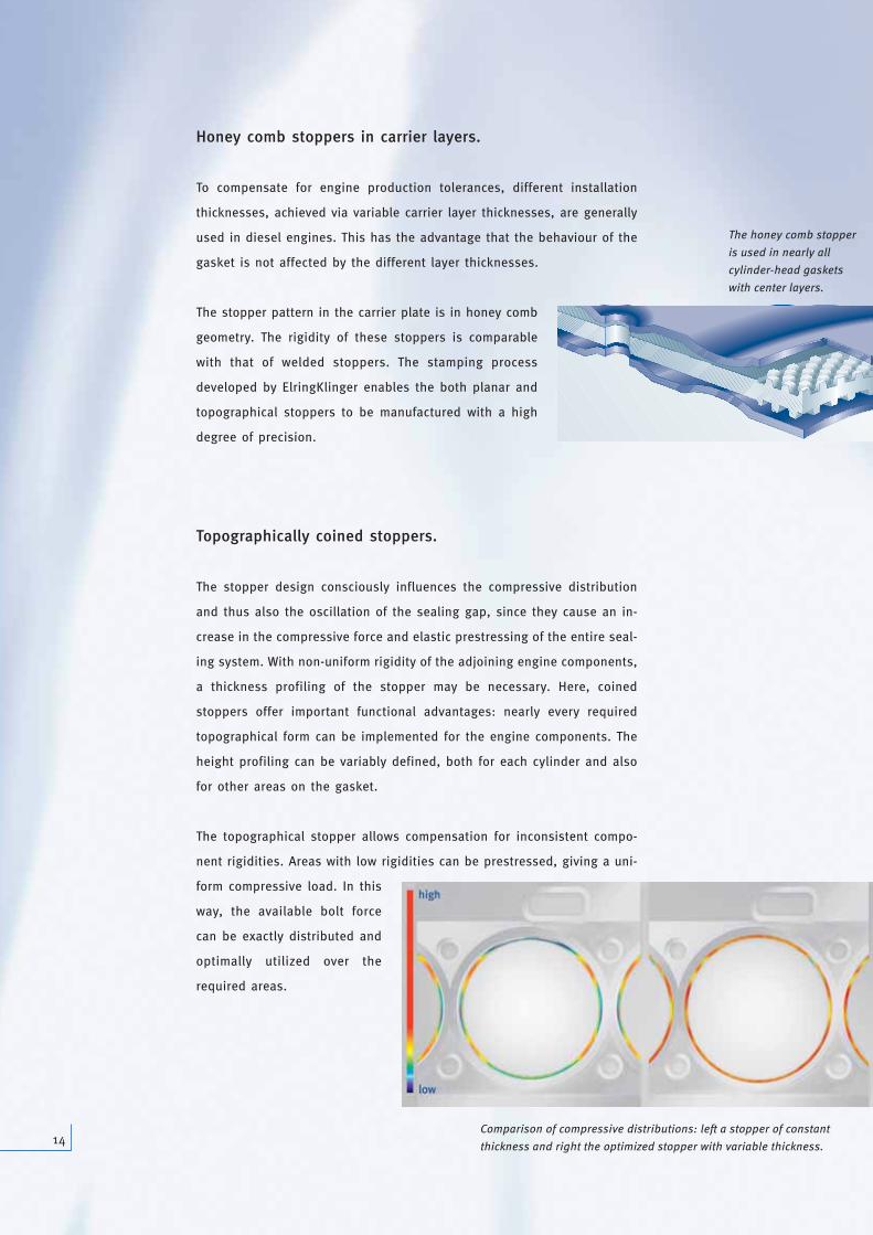
Topographically coined stoppers.
The stopper design consciously influences the compressive distribution
and thus also the oscillation of the sealing gap, since they cause an in-
crease in the compressive force and elastic prestressing of the entire seal-
ing system. With non-uniform rigidity of the adjoining engine components,
a thickness profiling of the stopper may be necessary. Here, coined
stoppers offer important functional advantages: nearly every required
topographical form can be implemented for the engine components. The
height profiling can be variably defined, both for each cylinder and also
for other areas on the gasket.
The topographical stopper allows compensation for inconsistent compo-
nent rigidities. Areas with low rigidities can be prestressed, giving a uni-
form compressive load. In this
way, the available bolt force
can be exactly distributed and
optimally utilized over the
required areas.
Comparison of compressive distributions: left a stopper of constant
thickness and right the optimized stopper with variable thickness.
The honey comb stopper
is used in nearly all
cylinder-head gaskets
with center layers.

15
Due to the partial elastomer coating, adapted to the required function,
only the surface areas of the cylinder-head gasket relevant for sealing are
coated. As a result, the surfaces standing free in coolant or oil can remain
uncoated, so that coatings no longer peel under critical marginal condi-
tions. Other advantages of this method: Due to the special procedure for
applying the coating, both the coating thickness and the coating medium
are selected according to the application. The somewhat differing coating
requirements in the combustion chamber and in the fluid area can then
be fulfilled selectively. Thus, for significant
component roughness or pores in the coolant
and oil seal, greater layer thickness and a soft-
er elastomer are advantageous. At the same
time, lower layer thicknesses are required for
sealing the ignition pressure in the combustion
chamber area. These goal conflicts are resolved
with the use of selective coating.
Example: newly developed coatings with opti-
mized frictional behaviour prevent the wear of
components when the engine is running. The
outstanding adaptability, which already exists at room temperature,
provides the basis for mastering the requirements in the cold leak test
immediately following installation.
Partial Coating – Less is More.
Partial coating:
ElringKlinger was the
first European manu-
facturer to introduce
this technology
in series production.

Designs – Customized for Best Performance.
16
No two engines are identical. In the same way, no two gaskets are. The
requirement: a variable sealing system which can be matched exactly to
the respective engine performance specifications. With Metaloflex® Elring-
Klinger has the right engineering answer.
Single-layer, 0.30 – 0.37 mm: design for gasoline engines.
Coined stopper: the stopper generation of the future –
with even greater functional potential
Laser-welded stopper: the proven solution –
has been in series production for many years
Two-layer, 0.50 – 0.65 mm: two functional layers. Design for gasoline engines and diesel engines subjected to high stresses,
without installation thickness matching. High sealing potential for the smallest installation thicknesses.
Three-layer, from 0.70 mm: two functional layers, one carrier layer. Design for diesel and gasoline engines with
installation thicknesses greater than 0.70 mm.
Four-layer, from 0.90 mm: with additional cover layer to compensate for surface imperfections on components
(porosity, cavities).
*
*
*
*
*These designs can also be equipped with topographical stoppers.
*
*

17
Depending on the respective parameters, the areas of application for the
different cylinder-head gasket designs overlap for each engine with
respect to the optimal technology and also cost effectiveness. With Meta-
loflex®, ElringKlinger offers a versatile, modern sealing system allowing
the development of the most effective and most economical solution for
all applications.
0
Bolt load/ignition force
2.5
50
100
150
200
250
2.4 2.3 2.2 2.1 2 1.9 1.8 1.7 1.6 1.5
Max. internal cylinder pressure [bar]
Typical areas of application for Metaloflex® cylinder-head gaskets in consideration
of the bolt load – ignition force ratio.

18
High-performance engines require high-performance gaskets. The out-
standing design flexibility of Metaloflex® allows optimally matched prod-
uct solutions for the respective engine conditions, even with extreme
requirements.
Metaloflex® as a multifunctional layer gasket with large
sealing gap vibration amplitudes.
If the sealing gap oscillations have a large amplitude, Metaloflex® is used
with three or four functional layers. This allows sealing over a larger spring
travel. ElringKlinger tunes the systems so that the entire spring travel is
always uniformly distributed over the beads. In connection with coined
stoppers, multifunctional layer gaskets with topographical stoppers can
also be manufactured. With this gasket design, durability is guaranteed
even under very critical dynamic conditions.
Design Solutions for Special Applications –Adaptation is Everything.
Four-function layer design with meander
stopper.
Three-function layer design with topo-
graphical honey comb stopper.
Three-function layer design with combi
stopper and topography.
Four-function layer design with standard
laser-welded stopper.
Four-function layer design: distribution of sealing gap vibrations over the four
function layers.

19
Metaloflex® cylinder-head gaskets with double stopper
for reciprocating engines offer a high degree of lifetime
reliability.
For engines with pressed-in or cast cylinder sleeves, ElringKlinger has
developed a Metaloflex® cylinder head gasket with double stopper system.
The required prestressing force is distributed over two stoppers, thus pre-
venting the danger of the liner sinking. This ensures lifetime reliability,
even under critical conditions. Here, coined stoppers – meander and
honey comb – offer exceptional possibilities for adapting to the engine
operating conditions, for example with the use of different stopper heights
in combination with a height profile.
Metaloflex® cylinder head gasket without stopper for
substantially reducing cylinder deformation.
This Metaloflex® design eliminates the stopper and therefore combustion
chamber camber at high compression. It consists of two function layers
with opposingly arranged beads in the main seal. A complex design is
required to guarantee the durability of the beads: bead deformation is no
longer determined by the stopper, but only by the operating range in the
engine and the dynamic sealing gap movements. ElringKlinger is the first
supplier in Europe to offer a series version of the stopper-free cylinder-
head gasket.
V8 engine with
cylinder liners.
Double stopper via folding and laser-
welded overlapping.
Meander double stopper. Honey comb double stopper.
Two-layer design without stopper.

ElringKlinger AG | Max-Eyth-Straße 2 | D-72581 Dettingen/Erms
Phone ++49 (0)71 23/724-0 | Fax ++49 (0)71 23/724-90 06 | [email protected] | www.elringklinger.de
The information included in this brochure is the result of technological investigations. They may be subject to changes depending on the design of the system. We reserve
the right to make technical changes and improvements. The information is not binding and does not represent promised properties. No claims for damages based on this
information will be recognised. We accept no liability for printing errors. 09
05
Lore
nz
& C
om
pa
ny