Metaloflex metal layer cylinder head gaskets. - … · · 2015-08-21Housing modules Topographic...
22
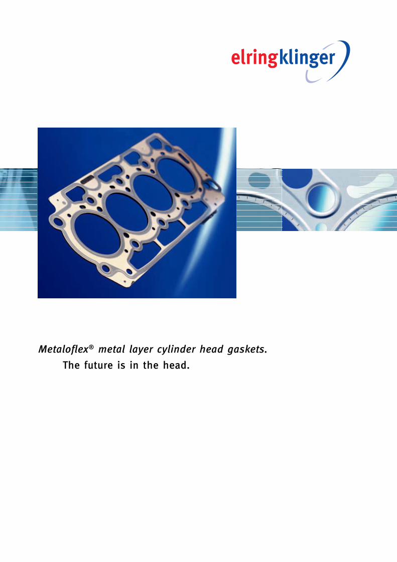
Metaloflex ® metal layer cylinder head gaskets. The future is in the head.
Transcript of Metaloflex metal layer cylinder head gaskets. - … · · 2015-08-21Housing modules Topographic...
09
05
Lore
nz&
Com
pany
Metaloflex® metal layer cylinder head gaskets.
The future is in the head.
09
07
1103_ZKD_Broschuere_GB_ro.qxd 30.08.2007 19:54 Uhr Seite 1
2
4 | Metaloflex® cylinder head gaskets
5 | Composition
6 | Coined stoppers
12 | Partial coating
13 | Designs
15 | Special design solutions
17 | Engineering
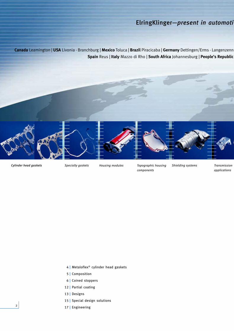
Canada Leamington | USA Livonia · Branchburg | Mexico Toluca | Brazil Piracicaba | Germany Dettingen/Erms · Langenzenn · Runk
Spain Reus | Italy Mazzo di Rho | South Africa Johannesburg | People’s Republic of Chi
ElringKlinger—present in automoti ve m
Cylinder head gaskets Specialty gaskets Transmission
applications
Shielding systemsHousing modules Topographic housing
components
1103_ZKD_Broschuere_GB_ro.qxd 30.08.2007 19:55 Uhr Seite 2

3
nzenn · Runkel · Bietigheim-Bissingen · Heidenheim/Brenz · Idstein · Rottenburg/Neckar | Great Britain Redcar · Gateshead
public of China Changchun | South Korea Changwon | Japan Tokyo | India Ranjangaon
moti ve markets throughout the world.
Bipolar plates
for fuel cells
mission
ations
Engine measuring
and testing services
PTFE componentsOriginal
Elring spare parts
Experience mobility—Drive the future:The ElringKlinger group of companies.
ElringKlinger—innovative development partner and series supplier to the
international automotive industry and other industries. We think ahead
and take on responsibility. For more sustainability and environmental
compatibility. Today and tomorrow.
Our trendsetting technologies and sophisticated product solutions con-
tribute to further reduce fuel consumption and emissions, and enable the
use of alternative fuels and the development of new drive technologies.
With comprehensive engineering and production expertise, we allow more
freedom of design for engines, transmissions, exhaust systems, and aux-
iliary aggregates. Together with our customers, we successfully promote
new technologies. To this end, we have around 3,400 employees working
at 21 locations throughout the world.
1103_ZKD_Broschuere_GB_ro.qxd 30.08.2007 19:55 Uhr Seite 3
Metaloflex® cylinder head gaskets. Solutions are born in the head.
4
In modern engines, Metaloflex® cylinder head gaskets (CHG) are well-
established as part of the global scene. As key components, they con-
tribute to efficient, reliable, and economical engine operation.
The cylinder head gasket ensures a reliable seal between the cylinder head
and block for fuel gases, coolants, and engine oil. It also acts as a load
transmission element between the crankcase and the cylinder head, and
as such, has considerable influence on the distribution of forces within
the entire distortion system and the resulting elastic component deforma-
tions.
Maximum freedom of design
Metaloflex® from ElringKlinger: globally recognized brand mark for inno-
vative metal layer CHG made of beaded, elastomer-coated spring steel
layers—single-layer or multi-layer depending on the application. Thanks to
the modular structure with the functional components including coating,
bead, and stopper, this sealing system can be adapted individually and
precisely to suit the specific requirements of the engine. And this saves
time-consuming and costly iterative steps in development and testing. For
maximum creative freedom required for engine design.
The technical strength of the metal layer CHG is especially apparent in
diesel engines and high-performance gasoline engines with direct injec-
tion. Introduced to the European market by ElringKlinger at the beginning
of the 90’s, today this sealing system reigns supreme in the internation-
al automotive industry. With Metaloflex®, ElringKlinger is the world’s
largest manufacturer of metal layer CHGs.
Innovations for even more performance and operating efficiency
Innovative coined stoppers including segment stoppers, honeycomb stop-
pers, and serpentine stoppers as well as dimple stoppers for backland
support, all of which can also be designed (topographically) with height
profiling, help achieve more economical solutions while simultaneously
increasing functional potential.
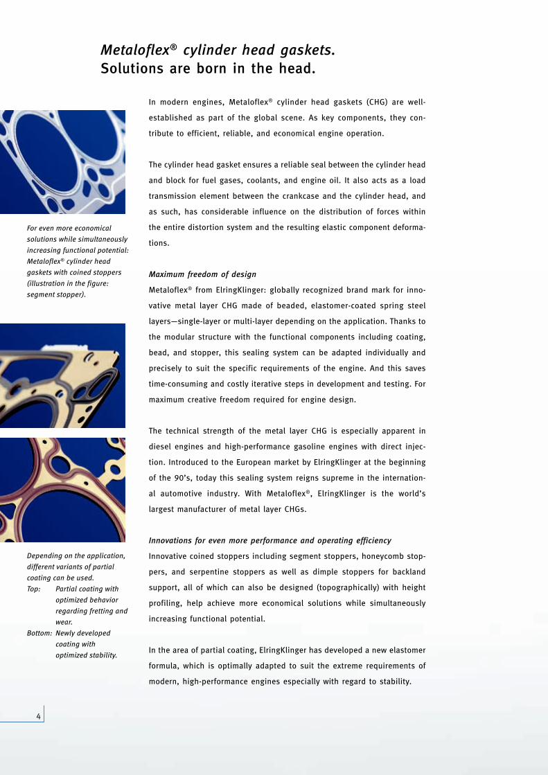
In the area of partial coating, ElringKlinger has developed a new elastomer
formula, which is optimally adapted to suit the extreme requirements of
modern, high-performance engines especially with regard to stability.
Depending on the application,
different variants of partial
coating can be used.
Top: Partial coating with
optimized behavior
regarding fretting and
wear.
Bottom: Newly developed
coating with
optimized stability.
For even more economical
solutions while simultaneously
increasing functional potential:
Metaloflex® cylinder head
gaskets with coined stoppers
(illustration in the figure:
segment stopper).
1103_ZKD_Broschuere_GB_ro.qxd 30.08.2007 19:55 Uhr Seite 4
5
Composition. Expertise in sealing systems, layer by layer.
Stephan 70% Typo 1/1
Korrektur siehe MANU S7
The optimum interaction of the individual design elements of Metaloflex®
metal layer CHGs guarantees the functionality and reliability of the seal-
ing system.
Half beads
Half beads generate two-line compression. They seal along the coolant and
engine oil passages, around the bolt holes, and the circumference of the
outer sealing contour.
Full beads
Full beads generate three-line compression around the circumference of
the combustion chamber. This elastic sealing element enables the sealing
of very high ignition pressures, even in the presence of large dynamic seal-
ing gap oscillations.
Functional layers
These elastomer-coated spring steel layers are equipped with elastic beads.
Center layer
The main function of the center layer is to adapt the gasket thickness to
the installation conditions required by the design.
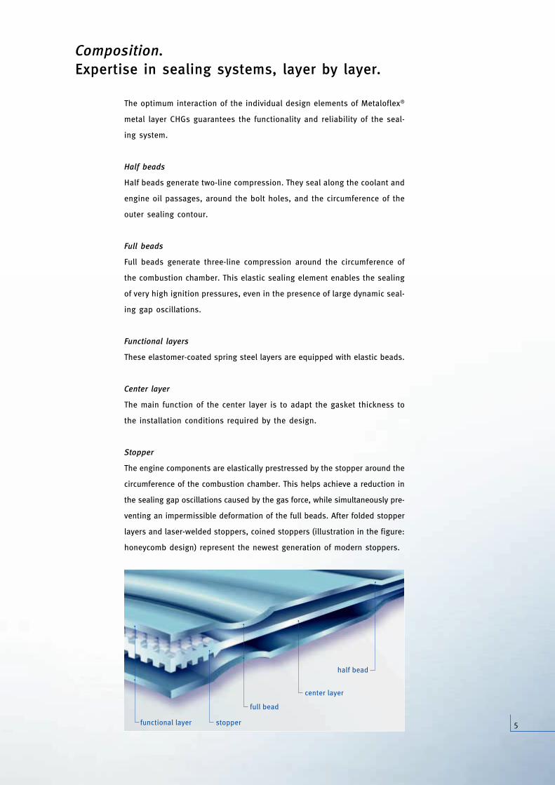
Stopper
The engine components are elastically prestressed by the stopper around the
circumference of the combustion chamber. This helps achieve a reduction in
the sealing gap oscillations caused by the gas force, while simultaneously pre-
venting an impermissible deformation of the full beads. After folded stopper
layers and laser-welded stoppers, coined stoppers (illustration in the figure:
honeycomb design) represent the newest generation of modern stoppers.
half bead
functional layer
full bead
center layer
stopper
1103_ZKD_Broschuere_GB_ro.qxd 30.08.2007 19:55 Uhr Seite 5
6
For design engineers, the new stamping technologies from ElringKlinger
open up a plurality of possibilities for influencing the distribution of forces
in the sealing gap. Metaloflex® cylinder head gaskets with coined segment
stoppers, honeycomb stoppers, and serpentine stoppers as well as dimple
stoppers for backland support offer additional decisive advantages in addi-
tion to high operating efficiency.
Expertise. From the very beginning.
In the last 10 years, the development of the cylinder head gasket has
essentially been characterized by the adaptation of the metal layer tech-
nology to the constantly increasing, diverse requirements of modern, high-
performance engines. As the leader in this technology, ElringKlinger has
repeatedly set new standards and further extended the limits of feasibil-
ity. With innovative sealing and production technology, we achieve even
more economical solutions, while simultaneously increasing the functional
potential. The development of the entirely new coined stopper is just one
such milestone.
After Metaloflex® CHGs were first equipped with doubled stopper layers,
ElringKlinger very successfully introduced laser-welded stoppers in series
production in the middle of the 90’s. In the meantime, the next change
of generation to the coined stopper was heralded. The objective of the
development process was to use suitable stamping technologies for pre-
senting the ideal stopper design for each Metaloflex® design. Basically, a
distinction is made between stopper patterns in spring steel layers, i.e.,
functional layers (segment, serpentine, dimple), and in the carrier plate
(honeycomb).
Still more design flexibility through supporting elements
The manufacturing process used for coined stoppers allows almost any
geometrical profiling with respect to both stopper width and stopper thick-
ness. Without restricting to the area of the classic stopper surface, the
design engineer now can avail of the possibility of integrating additional
supports almost anywhere on the gasket.
The third generation—coined stoppers. Flexible solutions with additional functions.
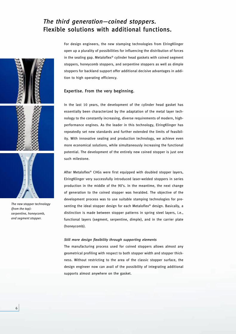
The new stopper technology
(from the top):
serpentine, honeycomb,
and segment stopper.
1103_ZKD_Broschuere_GB_ro.qxd 30.08.2007 19:55 Uhr Seite 6
7
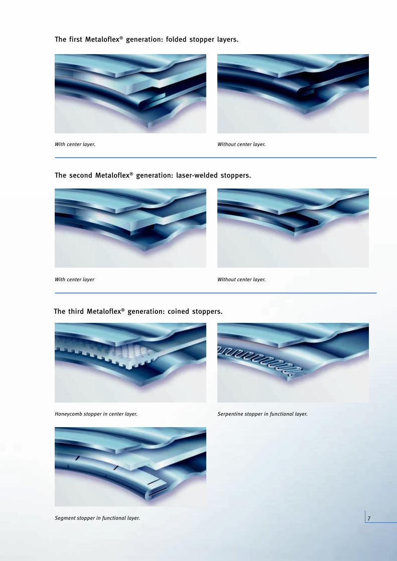
The second Metaloflex® generation: laser-welded stoppers.
The first Metaloflex® generation: folded stopper layers.
With center layer Without center layer.
With center layer. Without center layer.
Serpentine stopper in functional layer.Honeycomb stopper in center layer.
Segment stopper in functional layer.
The third Metaloflex® generation: coined stoppers.
1103_ZKD_Broschuere_GB_ro.qxd 30.08.2007 19:55 Uhr Seite 7
8
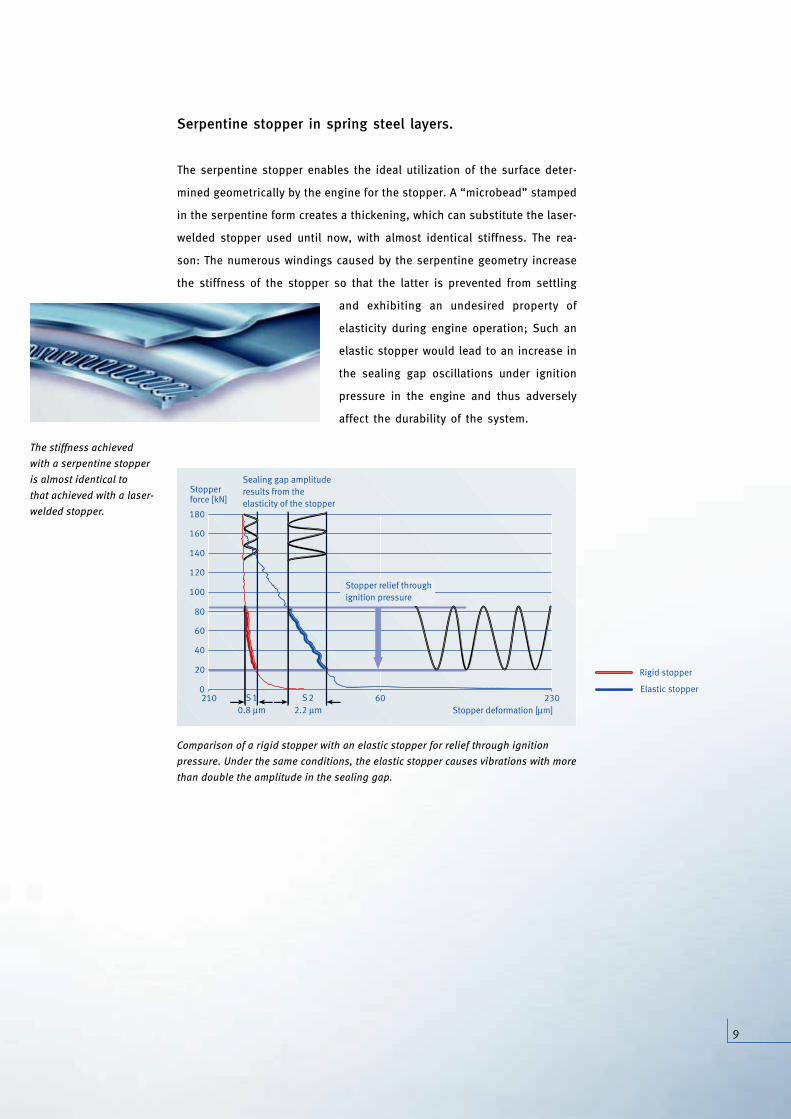
The honeycomb stopper
is used only in CHGs with
a center layer.
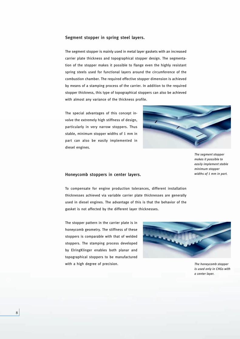
The segment stopper
makes it possible to
easily implement stable
minimum stopper
widths of 1 mm in part.
Segment stopper in spring steel layers.
The segment stopper is mainly used in metal layer gaskets with an increased
carrier plate thickness and topographical stopper design. The segmenta-
tion of the stopper makes it possible to flange even the highly resistant
spring steels used for functional layers around the circumference of the
combustion chamber. The required effective stopper dimension is achieved
by means of a stamping process of the carrier. In addition to the required
stopper thickness, this type of topographical stoppers can also be achieved
with almost any variance of the thickness profile.
The special advantages of this concept in-
volve the extremely high stiffness of design,
particularly in very narrow stoppers. Thus
stable, minimum stopper widths of 1 mm in
part can also be easily implemented in
diesel engines.
Honeycomb stoppers in center layers.
To compensate for engine production tolerances, different installation
thicknesses achieved via variable carrier plate thicknesses are generally
used in diesel engines. The advantage of this is that the behavior of the
gasket is not affected by the different layer thicknesses.
The stopper pattern in the carrier plate is in
honeycomb geometry. The stiffness of these
stoppers is comparable with that of welded
stoppers. The stamping process developed
by ElringKlinger enables both planar and
topographical stoppers to be manufactured
with a high degree of precision.
Th
w
is
th
w
1103_ZKD_Broschuere_GB_ro.qxd 30.08.2007 19:55 Uhr Seite 8
9
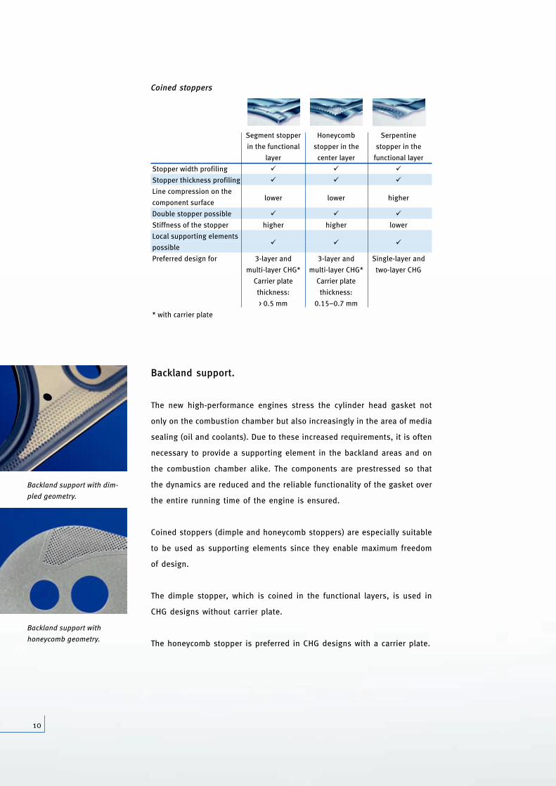
Serpentine stopper in spring steel layers.
The serpentine stopper enables the ideal utilization of the surface deter-
mined geometrically by the engine for the stopper. A “microbead” stamped
in the serpentine form creates a thickening, which can substitute the laser-
welded stopper used until now, with almost identical stiffness. The rea-
son: The numerous windings caused by the serpentine geometry increase
the stiffness of the stopper so that the latter is prevented from settling
and exhibiting an undesired property of
elasticity during engine operation; Such an
elastic stopper would lead to an increase in
the sealing gap oscillations under ignition
pressure in the engine and thus adversely
affect the durability of the system.
h
The stiffness achieved
with a serpentine stopper
is almost identical to
that achieved with a laser-
welded stopper.
Stopperforce [kN]
Stopper deformation [μm]
0
180
210 60 230
160
140
120
100
80
60
40
20
0.8 μm 2.2 μmS 1 S 2
Stopper relief throughignition pressure
Sealing gap amplituderesults from theelasticity of the stopper
Rigid stopper
Elastic stopper
Comparison of a rigid stopper with an elastic stopper for relief through ignition
pressure. Under the same conditions, the elastic stopper causes vibrations with more
than double the amplitude in the sealing gap.
1103_ZKD_Broschuere_GB_ro.qxd 30.08.2007 19:56 Uhr Seite 9
10
Backland support.
The new high-performance engines stress the cylinder head gasket not
only on the combustion chamber but also increasingly in the area of media
sealing (oil and coolants). Due to these increased requirements, it is often
necessary to provide a supporting element in the backland areas and on
the combustion chamber alike. The components are prestressed so that
the dynamics are reduced and the reliable functionality of the gasket over
the entire running time of the engine is ensured.
Coined stoppers (dimple and honeycomb stoppers) are especially suitable
to be used as supporting elements since they enable maximum freedom
of design.
The dimple stopper, which is coined in the functional layers, is used in
CHG designs without carrier plate.
The honeycomb stopper is preferred in CHG designs with a carrier plate.
Backland support with
honeycomb geometry.
Backland support with dim-
pled geometry.
Coined stoppers
Segment stopper Honeycomb Serpentine
in the functional stopper in the stopper in the
layer center layer functional layer
Stopper width profiling � � �
Stopper thickness profiling � � �
Line compression on the lower lower higher
component surface
Double stopper possible � � �
Stiffness of the stopper higher higher lower
Local supporting elements� � �
possible
Preferred design for 3-layer and 3-layer and Single-layer and
multi-layer CHG* multi-layer CHG* two-layer CHG
Carrier plate Carrier plate
thickness: thickness:
> 0.5 mm 0.15–0.7 mm
* with carrier plate
1103_ZKD_Broschuere_GB_ro.qxd 30.08.2007 19:56 Uhr Seite 10
11
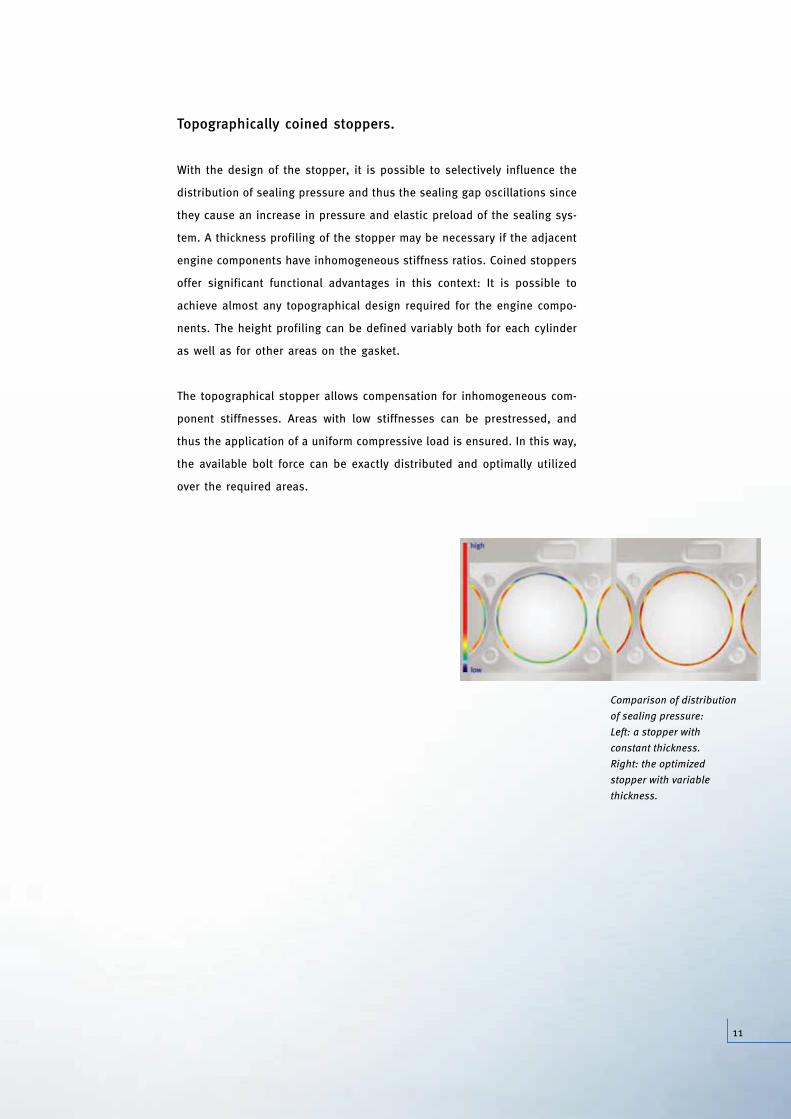
Topographically coined stoppers.
With the design of the stopper, it is possible to selectively influence the
distribution of sealing pressure and thus the sealing gap oscillations since
they cause an increase in pressure and elastic preload of the sealing sys-
tem. A thickness profiling of the stopper may be necessary if the adjacent
engine components have inhomogeneous stiffness ratios. Coined stoppers
offer significant functional advantages in this context: It is possible to
achieve almost any topographical design required for the engine compo-
nents. The height profiling can be defined variably both for each cylinder
as well as for other areas on the gasket.
The topographical stopper allows compensation for inhomogeneous com-
ponent stiffnesses. Areas with low stiffnesses can be prestressed, and
thus the application of a uniform compressive load is ensured. In this way,
the available bolt force can be exactly distributed and optimally utilized
over the required areas.
Comparison of distribution
of sealing pressure:
Left: a stopper with
constant thickness.
Right: the optimized
stopper with variable
thickness.
1103_ZKD_Broschuere_GB_ro.qxd 30.08.2007 19:56 Uhr Seite 11
12
Due to the partial elastomer coating, adapted to the required
function, only those surface areas of the CHG that are relevant
for sealing are coated. As a result, the sealing surfaces stand-
ing free in coolant or oil can remain uncoated, so that coatings
no longer peel under critical boundary conditions. Other advan-
tages of this process: The special coating application process
can be used to select both the coating thickness and the coat-
ing medium in an application-oriented fashion. The somewhat
differing coating requirements in the combustion chamber and
in the fluid area can then be fulfilled selectively. Thus, for exam-
ple, greater coating thickness and a softer elastomer are advan-
tageous for significant component roughness or pores in coolant
sealing and oil sealing. At the same time, lower coating thicknesses are
required for sealing the ignition pressure in the combustion chamber area.
These conflicts of objectives are resolved with the use of selective coat-
ing.
Newly developed coatings with optimized frictional behavior prevent wear
on the components during engine operation. The outstanding adaptability,
which already exists at room temperature, provides the basis for mastering
the requirements in the cold leak test immediately following installation.
Different variants of partial coating are used depending on the application.
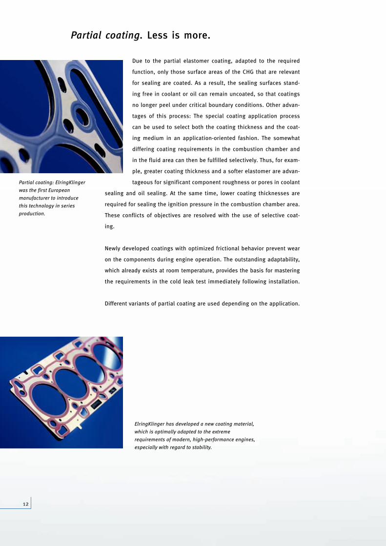
Partial coating: ElringKlinger
was the first European
manufacturer to introduce
this technology in series
production.
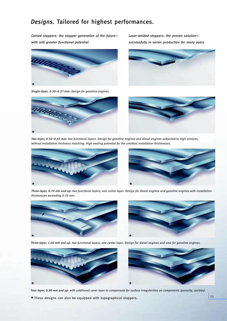
ElringKlinger has developed a new coating material,
which is optimally adapted to the extreme
requirements of modern, high-performance engines,
especially with regard to stability.
Partial coating. Less is more.
1103_ZKD_Broschuere_GB_ro.qxd 30.08.2007 19:56 Uhr Seite 12
13
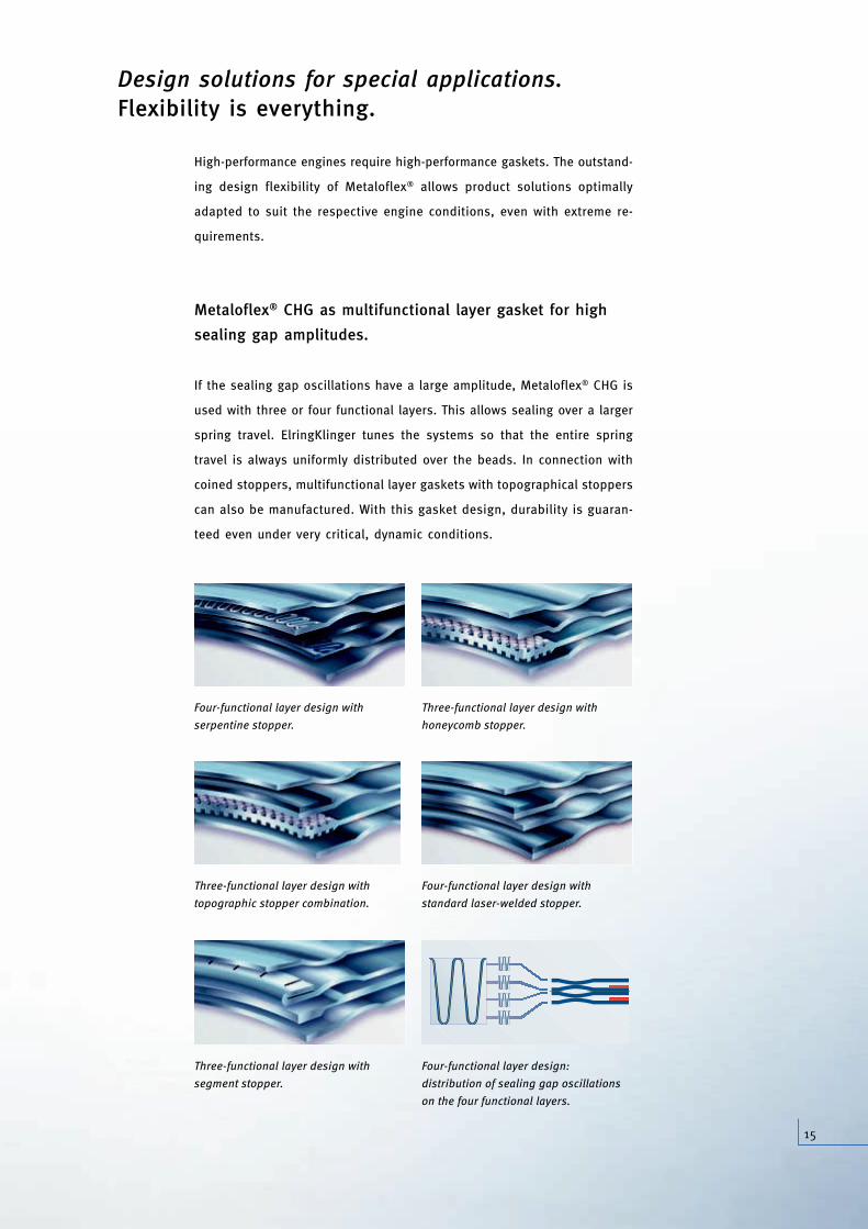
Designs. Tailored for highest performances.
Single-layer, 0.30–0.37 mm: design for gasoline engines.
Coined stoppers: the stopper generation of the future—
with still greater functional potential
Laser-welded stoppers: the proven solution—
successfully in series production for many years
Two-layer, 0.50–0.65 mm: two functional layers. Design for gasoline engines and diesel engines subjected to high stresses,
without installation thickness matching. High sealing potential for the smallest installation thicknesses.
Three-layer, 0.70 mm and up: two functional layers, one center layer. Design for diesel engines and gasoline engines with installation
thicknesses exceeding 0.70 mm.
Three-layer, 1.00 mm and up: two functional layers, one center layer. Design for diesel engines and also for gasoline engines.
*
*
*
*
*
*
Four-layer, 0.90 mm and up: with additional cover layer to compensate for surface irregularities on components (porosity, cavities).
*
* These designs can also be equipped with topographical stoppers.
*
1103_ZKD_Broschuere_GB_ro.qxd 30.08.2007 19:56 Uhr Seite 13

14
Depending on the respective influencing factors, a distinction can be made
between the ranges of applications of the different CHG designs. The opti-
mum technology for every engine, even with respect to operating efficiency.
With Metaloflex®, ElringKlinger provides a modern, versatile sealing system
allowing the development of the most effective and most economical solu-
tion for each application.
0
Bolt force/ignition force
2.5
50
100
150
200
250
2.4 2.3 2.2 2.1 2 1.9 1.8 1.7 1.6 1.5
Max. internal cylinder pressure [bar]
1.4 1.3
Typical ranges of applications of Metaloflex® CHG in consideration of the bolt
force/ignition force ratio.
Multifunctional layer gasket
Two-functional layer designwith topography
Two-functional layer designwithout topography
1103_ZKD_Broschuere_GB_ro.qxd 30.08.2007 19:56 Uhr Seite 14
15
Design solutions for special applications. Flexibility is everything.
High-performance engines require high-performance gaskets. The outstand-
ing design flexibility of Metaloflex® allows product solutions optimally
adapted to suit the respective engine conditions, even with extreme re-
quirements.
Metaloflex® CHG as multifunctional layer gasket for high
sealing gap amplitudes.
If the sealing gap oscillations have a large amplitude, Metaloflex® CHG is
used with three or four functional layers. This allows sealing over a larger
spring travel. ElringKlinger tunes the systems so that the entire spring
travel is always uniformly distributed over the beads. In connection with
coined stoppers, multifunctional layer gaskets with topographical stoppers
can also be manufactured. With this gasket design, durability is guaran-
teed even under very critical, dynamic conditions.
Four-functional layer design with
serpentine stopper.
Three-functional layer design with
honeycomb stopper.
Three-functional layer design with
topographic stopper combination.
Four-functional layer design with
standard laser-welded stopper.
Three-functional layer design with
segment stopper.
Four-functional layer design:
distribution of sealing gap oscillations
on the four functional layers.
asket
sign
sign
1103_ZKD_Broschuere_GB_ro.qxd 30.08.2007 19:56 Uhr Seite 15
16
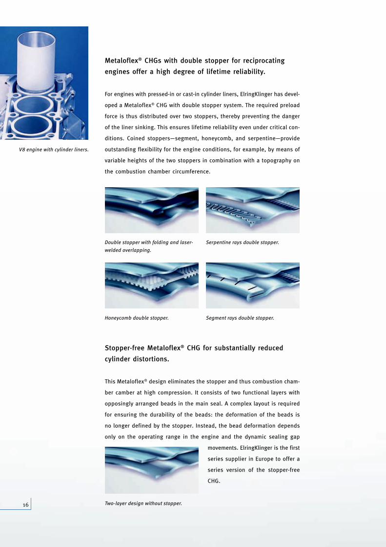
Metaloflex® CHGs with double stopper for reciprocating
engines offer a high degree of lifetime reliability.
For engines with pressed-in or cast-in cylinder liners, ElringKlinger has devel-
oped a Metaloflex® CHG with double stopper system. The required preload
force is thus distributed over two stoppers, thereby preventing the danger
of the liner sinking. This ensures lifetime reliability even under critical con-
ditions. Coined stoppers—segment, honeycomb, and serpentine—provide
outstanding flexibility for the engine conditions, for example, by means of
variable heights of the two stoppers in combination with a topography on
the combustion chamber circumference.
Stopper-free Metaloflex® CHG for substantially reduced
cylinder distortions.
This Metaloflex® design eliminates the stopper and thus combustion cham-
ber camber at high compression. It consists of two functional layers with
opposingly arranged beads in the main seal. A complex layout is required
for ensuring the durability of the beads: the deformation of the beads is
no longer defined by the stopper. Instead, the bead deformation depends
only on the operating range in the engine and the dynamic sealing gap
movements. ElringKlinger is the first
series supplier in Europe to offer a
series version of the stopper-free
CHG.
V8 engine with cylinder liners.
Double stopper with folding and laser-
welded overlapping.
Serpentine rays double stopper.
Honeycomb double stopper. Segment rays double stopper.
Two-layer design without stopper.
1103_ZKD_Broschuere_GB_ro.qxd 30.08.2007 19:57 Uhr Seite 16
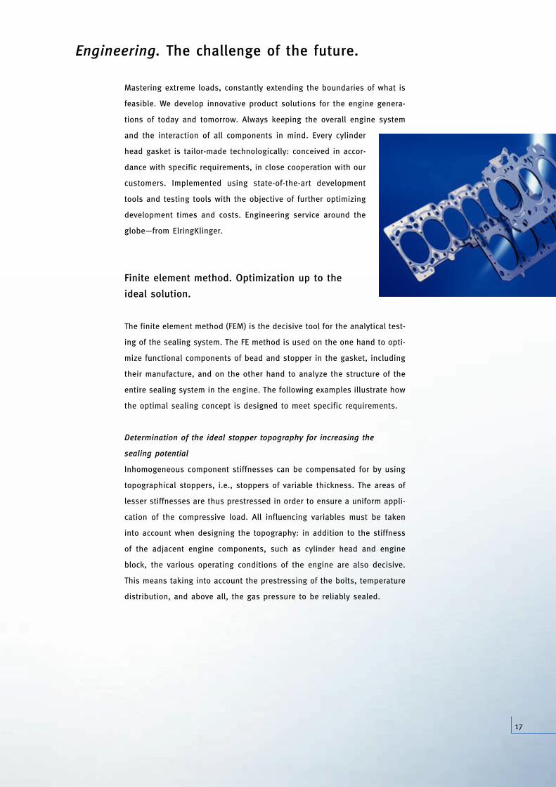
Mastering extreme loads, constantly extending the boundaries of what is
feasible. We develop innovative product solutions for the engine genera-
tions of today and tomorrow. Always keeping the overall engine system
and the interaction of all components in mind. Every cylinder
head gasket is tailor-made technologically: conceived in accor-
dance with specific requirements, in close cooperation with our
customers. Implemented using state-of-the-art development
tools and testing tools with the objective of further optimizing
development times and costs. Engineering service around the
globe—from ElringKlinger.
Finite element method. Optimization up to the
ideal solution.
The finite element method (FEM) is the decisive tool for the analytical test-
ing of the sealing system. The FE method is used on the one hand to opti-
mize functional components of bead and stopper in the gasket, including
their manufacture, and on the other hand to analyze the structure of the
entire sealing system in the engine. The following examples illustrate how
the optimal sealing concept is designed to meet specific requirements.
Determination of the ideal stopper topography for increasing the
sealing potential
Inhomogeneous component stiffnesses can be compensated for by using
topographical stoppers, i.e., stoppers of variable thickness. The areas of
lesser stiffnesses are thus prestressed in order to ensure a uniform appli-
cation of the compressive load. All influencing variables must be taken
into account when designing the topography: in addition to the stiffness
of the adjacent engine components, such as cylinder head and engine
block, the various operating conditions of the engine are also decisive.
This means taking into account the prestressing of the bolts, temperature
distribution, and above all, the gas pressure to be reliably sealed.
Engineering. The challenge of the future.
17
1103_ZKD_Broschuere_GB_ro.qxd 30.08.2007 19:57 Uhr Seite 17
18
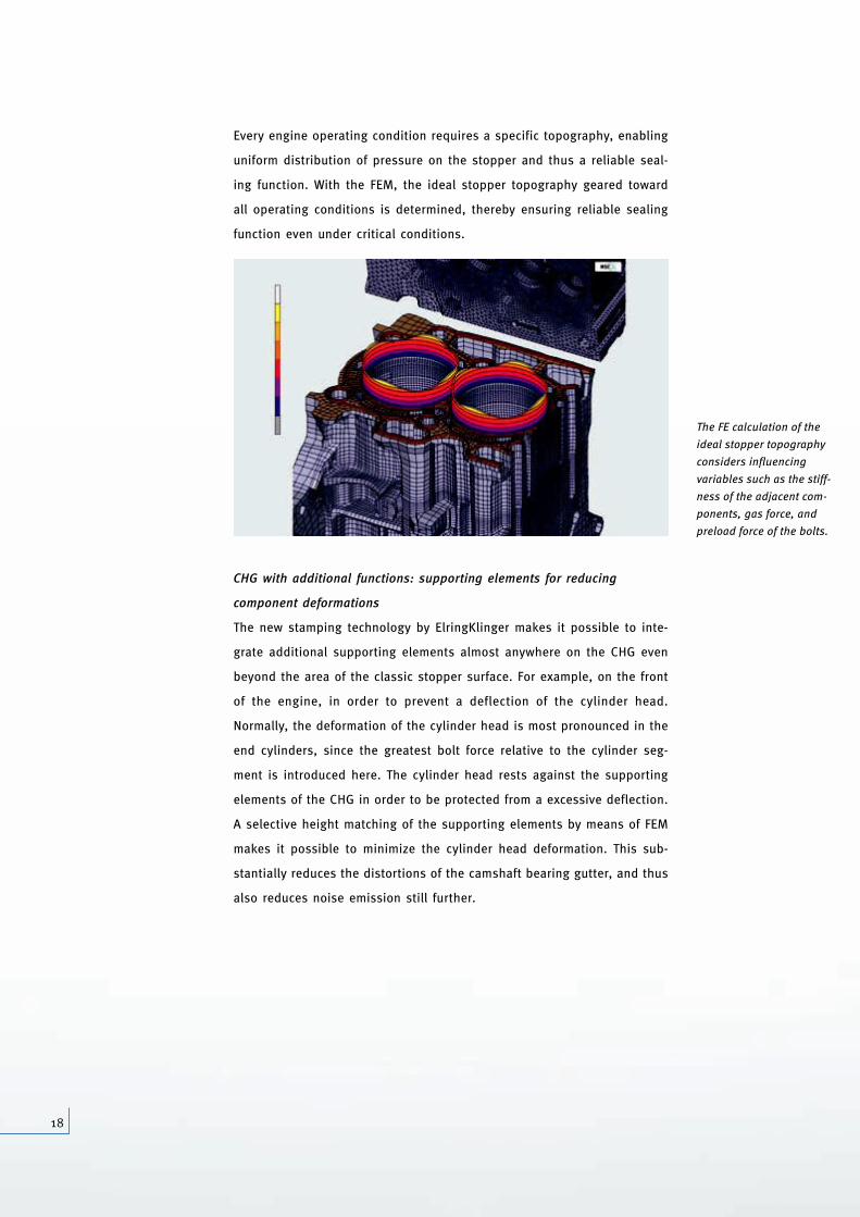
Every engine operating condition requires a specific topography, enabling
uniform distribution of pressure on the stopper and thus a reliable seal-
ing function. With the FEM, the ideal stopper topography geared toward
all operating conditions is determined, thereby ensuring reliable sealing
function even under critical conditions.
CHG with additional functions: supporting elements for reducing
component deformations
The new stamping technology by ElringKlinger makes it possible to inte-
grate additional supporting elements almost anywhere on the CHG even
beyond the area of the classic stopper surface. For example, on the front
of the engine, in order to prevent a deflection of the cylinder head.
Normally, the deformation of the cylinder head is most pronounced in the
end cylinders, since the greatest bolt force relative to the cylinder seg-
ment is introduced here. The cylinder head rests against the supporting
elements of the CHG in order to be protected from a excessive deflection.
A selective height matching of the supporting elements by means of FEM
makes it possible to minimize the cylinder head deformation. This sub-
stantially reduces the distortions of the camshaft bearing gutter, and thus
also reduces noise emission still further.
The FE calculation of the
ideal stopper topography
considers influencing
variables such as the stiff-
ness of the adjacent com-
ponents, gas force, and
preload force of the bolts.
1103_ZKD_Broschuere_GB_ro.qxd 30.08.2007 19:57 Uhr Seite 18
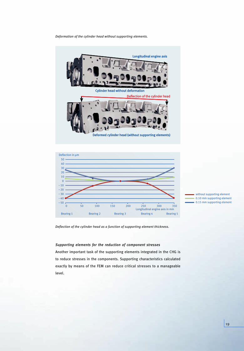
Cylinder head without deformation
Deformed cylinder head (without supporting elements)
Longitudinal engine axis
Deflection of the cylinder head
y
ff-
m-
s.
Deformation of the cylinder head without supporting elements.
Deflection of the cylinder head as a function of supporting element thickness.
Supporting elements for the reduction of component stresses
Another important task of the supporting elements integrated in the CHG is
to reduce stresses in the components. Supporting characteristics calculated
exactly by means of the FEM can reduce critical stresses to a manageable
level.
0– 50
Deflection in μm
Bearing 1
50 100
Bearing 2
150
Bearing 3
200 250
Bearing 4
300 350
Bearing 5
Longitudinal engine axis in mm
– 40
– 30
– 20
– 10
10
20
30
40
50
0
without supporting element0.10 mm supporting element0.15 mm supporting element
Cylinder head without deformation
Deformed cylinder head (without supporting elements)
Longitudinal engine axis
Deflection of the cylinder head
19
1103_ZKD_Broschuere_GB_ro.qxd 30.08.2007 19:57 Uhr Seite 19
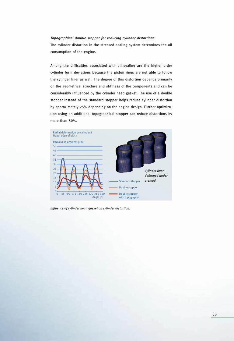
Topographical double stopper for reducing cylinder distortions
The cylinder distortion in the stressed sealing system determines the oil
consumption of the engine.
Among the difficulties associated with oil sealing are the higher order
cylinder form deviations because the piston rings are not able to follow
the cylinder liner as well. The degree of this distortion depends primarily
on the geometrical structure and stiffness of the components and can be
considerably influenced by the cylinder head gasket. The use of a double
stopper instead of the standard stopper helps reduce cylinder distortion
by approximately 25% depending on the engine design. Further optimiza-
tion using an additional topographical stopper can reduce distortions by
more than 50%.
Influence of cylinder head gasket on cylinder distortion.
Angle [°]
Radial displacement [μm]
Radial deformation on cylinder 3Upper edge of block
00 45 90 135 180 225 270 315 360
5
10
15
20
25
30
35
40
45
50
Standard stopper
Double stopper
Double stopperwith topography
Cylinder liner
deformed under
preload.
20
1103_ZKD_Broschuere_GB_ro.qxd 30.08.2007 19:57 Uhr Seite 20
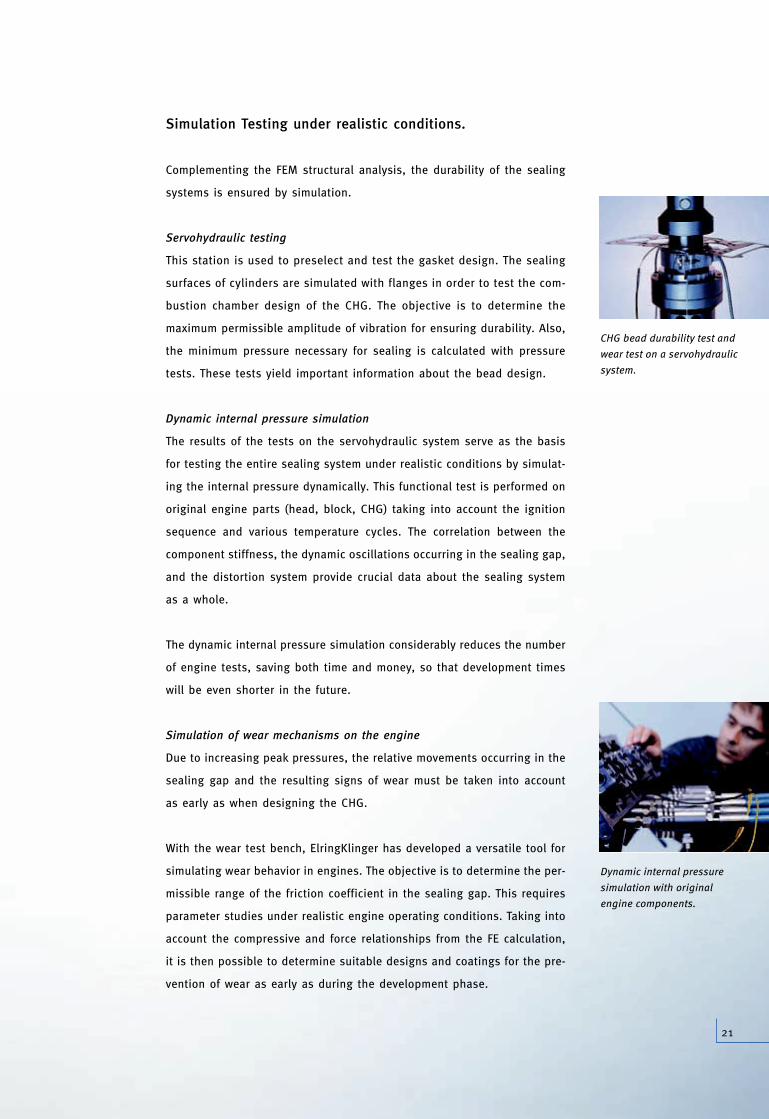
CHG bead durability test and
wear test on a servohydraulic
system.
Simulation Testing under realistic conditions.
Complementing the FEM structural analysis, the durability of the sealing
systems is ensured by simulation.
Servohydraulic testing
This station is used to preselect and test the gasket design. The sealing
surfaces of cylinders are simulated with flanges in order to test the com-
bustion chamber design of the CHG. The objective is to determine the
maximum permissible amplitude of vibration for ensuring durability. Also,
the minimum pressure necessary for sealing is calculated with pressure
tests. These tests yield important information about the bead design.
Dynamic internal pressure simulation
The results of the tests on the servohydraulic system serve as the basis
for testing the entire sealing system under realistic conditions by simulat-
ing the internal pressure dynamically. This functional test is performed on
original engine parts (head, block, CHG) taking into account the ignition
sequence and various temperature cycles. The correlation between the
component stiffness, the dynamic oscillations occurring in the sealing gap,
and the distortion system provide crucial data about the sealing system
as a whole.
The dynamic internal pressure simulation considerably reduces the number
of engine tests, saving both time and money, so that development times
will be even shorter in the future.
Simulation of wear mechanisms on the engine
Due to increasing peak pressures, the relative movements occurring in the
sealing gap and the resulting signs of wear must be taken into account
as early as when designing the CHG.
With the wear test bench, ElringKlinger has developed a versatile tool for
simulating wear behavior in engines. The objective is to determine the per-
missible range of the friction coefficient in the sealing gap. This requires
parameter studies under realistic engine operating conditions. Taking into
account the compressive and force relationships from the FE calculation,
it is then possible to determine suitable designs and coatings for the pre-
vention of wear as early as during the development phase.
Dynamic internal pressure
simulation with original
engine components.
21
1103_ZKD_Broschuere_GB_ro.qxd 30.08.2007 19:54 Uhr Seite 21

d
ic
ElringKlinger AG | Max-Eyth-Strasse 2 | 72581 Dettingen/Erms | Germany
Tel. +49 (0)71 23/724-0 | Fax +49 (0)71 23/724-90 06 | [email protected] | www.elringklinger.de
The information contained in this brochure is the result of technological analyses. They may be subject to changes depending on the design of the system. We reserve theright to make technical changes and improvements. The information is not binding and does not represent warranted characteristics. Any claims for compensation basedon this information shall not be recognized. We accept no liability for printing errors.
09
05
Lore
nz&
Com
pany
09
07
1
1103_ZKD_Broschuere_GB_ro.qxd 30.08.2007 19:54 Uhr Seite 22