Metallurgical Characteristics of High Strength Structural ...
98
NRL Report 6258 Metallurgical Characteristics of High Strength Structural Materials S[SiX'i'll (QLU:\RTI'IRI 'Y R PO'(RTI] W. S. PEh, INA, R. J. (;o , R. R V. l-tm:R, 1). (G. llowt. R. \V. 1 .v 1. l'. l'. l'u/.AK. K. B. LLoYD, E. L A. L N,1;: V.. A. WhFlti(:•:, 1, \V. (CrooKLR. R. E.. N •ORY, E. .). (C iA'.;, AND' 1.... \ (". .E" ,'l)'al?, $.,hcr I ) l(.i %n C{C7 $ II •**..N..V:I )ccc•EA bcv I ¶P.A1 (RA ( S. A' *J R'S- Z(II LABO~RATORV BestAvalableCopy , D0.CQ. Best Available Con\/-
Transcript of Metallurgical Characteristics of High Strength Structural ...

NRL Report 6258
Metallurgical Characteristics of
High Strength Structural MaterialsS[SiX'i'll (QLU:\RTI'IRI 'Y R PO'(RTI]
W. S. PEh, INA, R. J. (;o , R. R V. l-tm:R, 1). (G. llowt.
R. \V. 1 .v 1. l'. l'. l'u/.AK. K. B. LLoYD, E. L A. L N,1;:
V.. A. WhFlti(:•:, 1, \V. (CrooKLR. R. E.. N •ORY, E. .). (C iA'.;,
AND' 1.... \ (". .E"
,'l)'al?, $.,hcr I ) l(.i %n
C{C7$
II
•**..N..V:I )ccc•EA bcv I ¶P.A1 (RA (
S. A' *J R'S- Z(II LABO~RATORV
BestAvalableCopy , D0.CQ.
Best Available Con\/-

CONTEILTS
Abstract iiiProblem Status iiiAuthorization iii
INTRODUCTION
BACKGROUND ZTATEMENT: CONSIDERATIONS IN THEEVOLUTION OF ENGINEERING PRINCIPLES FOR THEOPTIMIZATION, DESIGN SELECTION AND SPECIFICATIONOF HIGH STRENGTH METALS FOR NAVAL STRUCTURES 4
(W.S. Pellini)
TITANIUM ALLOYS 14(R.J. Goode, R.W. Huber, and D.G. Howe)
Effect of Processing Variables on Strengthand Toughness of a Ti-7A]-2Cb-ITa Alloy 16
Diffusion-Bonded Titanium Alloy Plates 19
Fracture Toughness of 2-in. Thick TitaniumAlloy Plates 21
Heat-Treatment Studies on Some Titanium Alloys 21
ALUMINUM ALLOYS 22(R.W. Judy, Jr.)
HIGH STRENTII STEELS 23(P.P. Puzak, K.B. Lloyd, and E.A. DeFelice)
Review of 5Ni-Cr-Mo-V Steel Data 26
Explosion Bulge Tests of 5Ni-Cr-Mo-V Weldments 26
FRACTURE TOUGHNESS CHARACTERISTICS OF ANICKEL-BERYLLIUM, ALLOY 28
(R.J. Goode, R.W. Judy, Jr., and R.W. Huber)
NEW LABORATORY DROP-WEIGHr" BULGE TESTING FACILITY 30(R.J. Goode, E.A. Lange, and P.P., Puzak)
i

LOW CYCLE FATIGUE CRACK PPOPAGATIONSTUDIES OF Ti-6A1-4V, Ti-7A1-2Cb-lTa,AND UN•hLLOYED TITANIUm! 32
(T.W. Crooker, R.E. ,JEorey, and E.A. Lange)
Materials and Procedure 33
Strain Range Effects 34
Comparative Fatigue Performance 35
Corrosion Fatigue Effects 35
Conclusions 36
TITANI UM! CASTINGS 36(E.J. Chapin)
MODIFIED CHARPY TESTING PROCEDURES:THE FATIGUE CRACKED CHARPY AND SIDENOTCHED CHARPY IN IMPACT AND SLOWBEND TESTING 42
(L.J. McGeady
REFERENCES 46
TABLES 1 THROUGH 9 49
FIGURES 1 THROUGH 34 57
ii

ABSTRACT
A progress report coverin- research studies in hi 1hstrength hull structurai uaterials, conducted in theperiod Septerm.'Lcr 1964 to December 1964, is presented.Included in the report are fracture toughness studieson: (1) titanium alloys as related to processingvariables (including diffusion-bonding), thickness,and heat-treatment, (2) aluminum, (3) high strengthsteels relating primarily to the 5Ni-Cr-Mo-V steels,and (4) a nickel-beryllium alloy. Low cycle fatiguecrack propagation studies on several titanium alloysare presented as well as a general review of thestatus of the titanium casting industry. The U.S.Naval Research Laboratory's new 240,000 ft-lb labora-tory drop-weight bulge testing facility is de!:scribedand a preliminary correlation of the rc,_ults obtainedwith it and the explosion bulge test are presented.The results of a study using fatigue cracked and sidenotched Charpy specimens in impact and slow bendtesting on a wide variety of steels is given. Theresults are compared to those obtained in the standardCharpy test using the same materials. A backgroundstatement describing the "philosophy" of testing andevaluation of high strength structural materials whichis the basis of the program is included in this report.
PROBLEM STATUS
This is a progress report; work is continuing
AUTHORIZATION
Projects SR 007-01-02-0704, RR 007-01-46-5405, andWW 041-63RO5-24A NRL Problem M01-05
Projects RR 007-01-46-5420 and SR 007-01-01-0856, andWW 041-63RO5-24B NRL Problem MOl-18
Projects SR 007-01-01-0850 and SR 007-01-01-0854NRL Problem M03-01
Manuscript submitted February 15, 1965.
iii

METALLURGICAL CILRACTERISTICS
OF HIGH STRENGTH STRUCTURAL MATEPIALS
(Sixth Quarterly Report)
INTRODUCTION
This is the sixth status report covering the U.S. NavalResearch Laboratory Metallurgy Division's long-ran ,eprogram of determining the performance characterinticsof high strength materials. The program is prima-ilyaimed at determining the fracture toughness character-istics of these materials using standard and newlydeveloped laboratory test methods and at establi ihingthe significance of the laboratory tests for predictingthe service performance of the materials in largestructures. The program is aimed at Navy requiierientsbut the information that is developed is pertinent toall structural use of these high strength materials.Quenched and tempered (Q&T) steels, maraging steels,titanium alloys, and aluminum alloys, are the principalhigh strength materials currently under investigation.
Since these status reports are now receiving a muchbroader distribution than they have in the past, abackground statement which considers the evolution ofengineering principles for optimization, design selec-tion, and specification of new high strength structuralmaterials is presented. The background statement alsopresents the "philosophy of testing and evaluation"which is followed in investigating these materials toprovide useful and meaningful information at theearliest possible date.
The effect of processing variables on the fracturetoughness of a Ti-7Al-2Cb-ITa alloy is evaluated withthe U.S. Naval Research Laboratory',-; drop-weight teartest (DWTT). The results show that sizable variationsin toughness and strength are possible with this alloy

through careful control of processing variablesand that thL full thickness DWTT is most useful inshowing the variations in fr.:ture toughness withprocessing. The effect of heat treatment anddiffusion-bonding on the strength and toughnessproperties of some titanium alloys is presentedalong with some fracture toughness measurementson 2-in. thick titanium alloy plates.
The results of fracture toughness studies on aluminumalloys as developed to date are rcported and a pre-liminary fracture toughnes.s diagram is presented.The results presently show that most of the aluminumalloys stucied are capable of developing high levelsof plastic strain in the presence of flaws, even atfairly low DWTT energies.
A review was made of the 5Ni-Cr-Mo-V steel datadeveloped under the Bureau of Ships 130-150 ksiyield strength hull steel contract. From this, itis seen that high quality electric furnace practiceusing two oxidizing and one reducing slags res-ultedin a material of high fracture toughness. Explosionbulge tests (performed at NRL) of undermatching,matching, and overmatching weldments of the materialat the 140 ksi strength level (base plate) showedthat the heat-affected-zone (HAZ) was not subject toas great a straining as was the unaffected platematerial. These tests were aimed at defining therelative strain conditions in mismatched weldmentsof the 5Ni-Cr-Mo-V steel.
A brief study of the fracture toughn-ess character-istics of' a Ni-l.95B[e-0.5Ti alloy (Berylco-Nickel 440)was made at two extreme levels of yield strength(47.8 ksi and 177.5 ksi). The study indicates thatthe alloy can develop a high level of toughness, asmeasured by the DWTT, at both strength levels andsince simple heat treatm,.ents can be used to developintermediate levels of strength and toughness, a morethoroug;h investigation of this and related alloyscould be of interest.
A new labor" tory drop-weight bulge testing facilityat NtL is c .,scribed in which the capacity of thedrop-weight machine (2,10,000 ft-lb) exceeds that
2

available in the NRL explosion bulge test facilitywhich is limited to the u-e of 7-lb. Puntolite (.The
facility was developed to evaluate weldrnents in steels,titanium,aluminum, and ot her high striength metals in
the thickness range of 1 - 2 inches. Preliminarydrop-weight bulge tests of 1-inch thick 150 ksi yield
strength steels are presented arnd are correlated to
the results obtained in the standard explosion bulge
test.
Low cycle fatigue crack propagation studies of
Ti-6A1-4V, Ti-7AI-2Cb-lra, and unalloyed titanium
are presented. From these studies, it is concluded
that the growth rate.- of low cycle fatigue cracks
in the materials follow the form
L•L !A, K ((T T)n
the growth rt:i es iin thv two alloy1-s are very sensitive
to smIall chalnges in applied -strain and become quite
rapid :It cyclic .;train levels !)1 t h(, proportional
limit. In a salt water enviroirrnent there is consider-
able effect on the crack growth rate of the Ti-7A1-2Cb-lTa alloy.
A review of the titanium castings industry is in-
cluded in this status report which points out thecapabilities and limitations of the industry as is
known today. This is a pre*liminary to possible future
work in surveying the fracture toughness characteristicsof titanium alloy ca.stings.
The use of the fatigue cracked Charpy and side notched
Charpy in impact and sJ ow bend testing has beer in-
vestigated for a varicty of high strength steelsranginrg in yield s;trength from 80 ksi to 2F0 ksi.
Correlatý ns between the st.',ndird Charpy V and these
modified tests have been determined. The results of
the study show that nro imrnediate2 advantage Is gailed
by usiing the modified tests in lieu of the standard
Charpv V test . and that discriminatiion bet'Aeen thesteels is drastically retduced, especially at the lower
levels of toughness, when fatig, e nottchinog proceduresare used.
3

BACKGROUND STATEMENT:
CONSIDERATIONS IN THE EVOLUTION OF
ENGINEERING PRINCIPLES FOR THE OPTIMIZATION,
DESIGN SELECTION, AND SPECIFICATION OF HIGH
STRENGTH METALS FOR NAVAL STRUCTURES
(W.S. Pellini)
As a consequence of a greatly increased interest in Navy,Department of Defense, and industrial circles in militarystructural application of high strength ,etals, thepublication of the sixth quarterly report of this seriesis being provided to a considerably expanded distribu-tion list of interested parties. Accordingly, thesereports, which began as a method of quick disseminationof information to a limited circle of Navy specialistsfully conversant with the general aims of the studies,now require redefinition of general aims to a muchlarger audience. Basically, the subject U.S. NavalResearch Laboratory program resulted from an assign-ment by the U.S. Bureau of Ships for studies to defineengineering criteria by which the practicability offracture-safe design of naval structures based on the"new" classes of high strength metals could be defined.It is important to recognize that the term "navalstructures" is not restricted to a particular type ofpressure hull for submarines (these may range fromsimple spheres to complex, large, "roughly" cylin-drical structures) but includes ship hulls, hydrofoils,large internally loaded pressure tanks, large deep-ocean civil engineering structures, etc. In otherwords, the desired information should be such as tohave general parametric applicability in des-ign trade-off considerations for any type of structure. Theprincipal difference, with respect to the use of thesematerials in naval applications, is that the generalsize of the structures and the thickness of the mater-ials tend to be on the "massive" side and severe en-vironmental conditions may be encountered. For themost part, high strength metals have been used previouslyin rather thin sections and under r-ther carefully con-trolled environmental conditio ,. The history of these
4

previous applications also included full scale-up fabri-cation of sections of prototypes which were tested todestruction and the "weak" points redesligned untiloptimum perfor:mance was obtained; viz., rocket cases,aircraft forgings, etc. In contrast, the naval archi-tect is often involved with structural problems whichmay exclude such approaches and simultaneously requiremeeting of severe service conditions including thedevelopment of localized or general plastic overloads.In many complex naval structures, localized plasticoverloads are to be expected if reasonable generalstructural efficiency is to be attalned and if shockloads are applied. The possibility of explosionattack resulting in plastic overloads is anothermatter of possible parametric consideration. If itis possible to define the level of stress (elasticor plastic) that critical structural element positionscan withstand in the presence of flaws or cracks,we cankthen proceed to select materials within what-ever particular limitations the designer is requiredto accept. In other words, the essence of the studiesis the evolution of the parametric mat rix of metalcapabilities that apply not only to an ic!ealizedlaboratory test element but also to a practicallyfabricated article, including weld joints and complexgeometries.
We should remember that large structures built of lowstrength ste~l have failed catastrophically and ap-proximately fifteen years of applied research wasrequired to evolve solutions (1). In this case, theproblem was simply one of "transition temperature" --in other words, a single metallurgical failure mechan-ism (cleavage) was operative and such failures alwaysoccurred by crack propagation through the base metal.With the advent of quenched and tempered steels, failureshave been noted which may be considered "anomalous"in the sense that a variety of other fracture modes --fracture propagation through welds, heat-affected-zones(HAZ), or fusion line (2) -- may be encountered. Hydro-gen embrittlement, stress corrosion cracking, and otherenvironmentai factors plagued the applications to air-craft and rocket cases. Age-hardened aluminum alloyshave developed catastrophic failures, in naval servicedue to metallurgical conditions that could be tracedentirely to the "softened" HAZ of weldmeri-ts.This listing is not meant to be all-inclusive
5

but to highlight the fact that anomalies or "surprises"may be expected in the applications of these newmetals and it is best to discover these in the labora-tory rather than to be surprised in service. In pro-jecting to the use of these new materials, we are facedwith problems of greater complexity (because of thevariety of failure mode possibilities) than for thebrittle fracture problems of low strength steels.
The U.S. Naval Research Laboratory Metallurgy Division'sprogram in high strength structural metals is but apart of the Navy-wide research effort in this field,but it is a crucial part because it is concerned withthe nature of failure mechanisms and with the develop-ment of practical test methods for the study and evalua-tion of the inherent resistance of the various metalsto their particular set of failure modes. The subjectprogress reports represent a gradual evolution of theparametric structure by which these analyses can bemade; coupled to these studies there are other in'vesti-gations covered by a quarterly report (3,4) series(recently initiated) dealing with corrosion aspects.
There is no escape from the complexity of utilizinghigh strength metals, simply by a switch to non-metals or to glass composite structlIxes. All ofthese have their crucial relationships between the"laboratory defined" strength of materials and theeffective strength of a structure. These aspectshave been generally reviewed and considered by theUndersea Technology Panel of Project Seabed (5).For many o these materials we are in the unfortunatestage at which "design confidence in their utiliza-tion is inversely proportional to the technologicalknowledge that has been accumulated." In other words,we do not know enough to realize what we should beconcerned about. This may be described as Stage 1.Sage 2, which generally follows, involves disen-chantment with the material because of difficultiesthat becume apparent, and Stage 3 then brings us tobuilding sound technical bases for use of the materialsby the proper combination of design and fabricationtechniques, within realistic limits. It is only atStage 3 that "design confidence becomes proportionalto knowledge." For example, for quenched and tempered
6

steels of the HY-130/150 ksi yield strength range weare in Stage 3; for maraging; steels in thick sectionswe have entered Stage 2; for thick Litanium alloyswe are approaching Stage 2; for glass and fiber-rein-forced-plastics (FflP)TVweaire in Stage 1. The parti-cular stage may be 1, 2, or 3 depending on size andcomplexity of the structure contemplated. Theseestimates (the author's) are roughly qualitativeand intended only for emphasis of a point of philoso-phy, without which we can readily confuse R&D "imagin-eering" with the practical realities of true engineer-ing capabi ities.
It is most important that we "stand off" and take agood perceptive look at where we are technically andthe directions that are indicated for R&D in this field.There is much confusion developing from the "race" todesign and build structures utilizing these new mater-ials. Claims, counterclaims, partial information,and misinformation prevail -- the temptation is con-siderable to treat these materials as a general classsubject to definitions covered by a few simple gener-alities. In fact, we are dealing with highly "in-dividualistic" materials comprising several distinctlydifferent families of quenched and tempered steels,maraging steels, titanium alloys, and aluminum alloys.The problem of utilizing these materials in "fracture-safe design" cannot be resolved solely from simpletests of selected "base material" meaning the plateor forging, as produced experimentally. Processing,fabrication, and design configuration variables haveimportant interrelationships -- it is essential thatthese be understood in a general sense before much morecan be said. As a start, let us consider the threemajor classes of"discrimination" factors which mustserve as the starting point for any and all analysesof suitability:
(1) Structural discrimination factors: Is thecontemplated structure subject to rigorous stress analysisor is it complex with a requirement for plastic hingereadjustment at points which are relatively "stress in-determinate"? Certain aerospace and aircraft componentshave been built with "near perfection" design and fabri-cation techniques. The ground rules which can apply tomaterials selection for such structures cannot be trans-lated to more conventionally designed and fabricatedstructures. Moreover, as size increases the retentionof "perfection"design and fabrication procedures becomeimpossible or temporarily beyond the "state of the art".
7

(2) Materials discrimination factors: Under certain•Tcondit1onr-Texampie -- no -TTUi-i--ase plate is the
"discrimiination factor" with respect to fracture-safedesign. To the limits that structural design and fabri-cation permit "rigorous", "approximate", or "indeterminate"definition of the flaw size and stress, the analyses ofrequired fracture toughness can be restricted to basemetal characteristics. However, if welds are present,the crucial discrimination factors may become the weld,the heat-affected-zone (IIAZ), or the fusion line zone.In other words, conditions may exist for which the frac-ture-safe, allowable local and general stress levels forthe base material are greatly in excess of those permissi-ble for the weld zone area.
(3) Environmental discrimination factors: For singlecycle loadingfatigue is not a factoTr" however, for re-peated loading, low cycle fatigue may play an importantrole in flaw generation and growth. Thus, the initialflaw size condition of the structure may not be thediscrimination flaw size for fracture-safe design. Inthe presence of moisti're or seawater, the rate of fatiguecrack growth may be greatly increased; moreover, thecritical stress for fracture initiation may be grosslydecreased. These two factors can work in concert orseparately; also, the response of the base metal may bespecifically different from that of weld zones in theserespects.
The permutation of these factors may suggest that we areinvolved with an "impossible" problem of utilizing highstrength metals. This is not the case for the followingsimple reasons:
(A) For some modestly high level of strength (forany given metal), high fracture toughness will be "inherent"(built into) in the metal and the weld zone and environ-mental aspects will be of no significant consequence fora reasonable design. This simply means that relativelycomplex structures (within reason) can be constructed withrelatively conventional fabrication and fracture safetywill be assured. The "guarantee" comes from metallurgicalaccompli shment.
(B) For some intermediate (somewhat higher) levelsof strength, the same can be said (as above) for the basematerial but not for the weld zone. Discrimination analysismay suggest location of welds at regions of low stress,
a

etc., or elimination of welds. In this respect, itshould not be forgotten that improved welding techniquesare being evolved to cope with this problem. In fact,this is an area of utmost fruitfulness and high poten-tial payoff. The "guarantee" must come from a combina--tion of metallurgical, design, and fabrication factors.
(C) For a much higher level of strength (thehighest range) the base metal becomes highly fracturesensitive at flaw size-stress combinations that are dif-ficult to avoid and environmental factors become highlycontrolling in addition. These materials can and arebeing used within their limitations -- however, it ismost important to recognize that perfection of design,flaw size control, fabrication finesse, and precisecontrol of environmental aspects are of paramount im.portance. The "guarantee" must come from design andfabrication factors with possible severe penalties infactors of safety that must be utilized.
Now, a great deal of the effort conducted under thepresent program relates to characterizing the variousnew materials in a "first cut" approach as to strengthlevel limits related to categories (A), (B), or (C) asoutlined above. In these respects, it should be recog-nized that fracture toughness charactcristicz of a metalat a given level of strength are highly sen:sitive toprocess history, thickness, welding techniques, etc.Thus, the "first cut" approach must be aimed at evalu-ating the best that can be done for specific rangesof strength within realistic limits of production con-sistency attainability. The importance of understand-ing the virtues or limitations of the best materialswithin specified strength ranges lies in the preventionof the application of undue restrictions on design andfabrication (more perfection than is necessary thusleading to an expensive structure) for basically frac-ture tough materials. Obviously, there is the otherpossibility of using less than the required restrictionsfor materials of low fracture toughness. Another reasonlies in the elimination of much misused "factors ofsafety" solutionswhich are self-negating and lead tomismatch between attained structural efficiency and thecost for the attainment. An example of this situationmay be found in the construction of large diameter solidpropellant booster cases of 250 ksi yield strength (nominal)maraging steel. At this strength level the steel (approxi-mately 374-in. thickness) has a very high sensitivity for
9

fracture initiation at high stresses (relative to yield)frora very small flaws. If used at low hoop stresses (sayapproxirately 0.6 of the biaxial yield strength), arelatively large flaw is tolerable, provided no adverseenvirorn::ýntal effect is present. Now, the point is thatfabrication of 250 ksi steel is much more difficult andthe cost is higher than say for a 150-160 ksi steel. Atthe lower strength level, the steel and weld can be metal-lurgically constituted to have high fracture toughnesswhich in turn allows hoop stressing to very high stressesexceeding the biaxial yield strength and environmentaleffects are relatively minor. The choice of either ahigh factor of safety applied to a high strength brittlematerial or a very low factor of safety applied to a lowerstrength, fracture tough material does not necessarilylead to a structure of equivalent fracture safety. Infact, environmental aspects considered, higher reliabilitycould be attained with the lower strength steel. Thesefactors become much more important for structures whichare expected to have long life and which deviate from theutmost simplicity of design inherent to simple spheres orcylinders.
The foregoing discussions were intended as "prologue" fordefinition of the aims of the studies reported in thisand in the previous five progress reports. The primaryaims may be summarized as follows:
(1) To evolve frame-of-reference ("yardstick")categorization of the relative fracture toughness ofcompeting high strength material -- from very low tovery high levels of strength.
(2) To use this information for purposes of deter-mining trends and directions in optimizing the strength-fracture toughness relationships of the various materials.That is to say -- as R&D direction guidelines.
(3) To evolve information of early usefulness todesigners faced with near-term decisions in the appli-cations of these materials. In this respect, "time isof essence" and data interpretation finesse is of secondaryimportance. Finesse in these respects will evolve withtime -- for the present, the attainment of reasonablyinterpretable engineering information is the first orderof business.
It is inconceivable that near-term design decisions for
10

thick walled structures will, be made with data of highdiscrimination finesse -- there simply is not enoughtime to develop such detailed experience. It is rmoreconceivable that decisions riust be made on relatiwvelylittle data and the temnptation will exist to proceedon this "too little" data basis, particularly forthick sections. The motivation of this program is toestablish a reasonably sound basis for evaluation ofrelatively large size, thick walled structural elementsof materials for which there is no prior experience inpractical applications. Two opposing philosophies:; haveto be contended with -- one involves projection (guess-ing) what the properties may be, candidly referred toas "extrapolation" -- the other involves "ivory tower"promises of the ultimate in R&D (given enough tille)when everyLhtng will be known exactly. A moderate mid-dle course program is of essence -- in this respect.the scope and magnitude of the subject NPJL effort isat the maximum practical rate. To date, a rationalexploration has been made for materials of 1-in. thick-ness; as rapidly as possible, we are extending thesestudies to 2-in. thickness and then to thicker sections.The problems of procuring such materials are severe,both from the point of view of commercial availability(many are considered experimental materials) and fromthe point of cost required to obtain samples repre-senta-tive of large scale production. For example, a test ofa 3-in. thick plate of say 12-in. x 12-in. laboratoryproduced dimensions is meaningless insofar as represent-ing a production plate.
As noted previously, a companion quarterly progressreport involving corrosion (stress corrosion cracking,cathodic protection, etc.) aspects of high strengthmaterial is issued separately. In many cases the samematerials reported in the present series of reportsare "transferred" to the NRL group involved withcorrosion studies.
The potentials of plane strain Kic (linear elasticanalysis -- fracture meehanics) categorization ofmaterial is being investigated. These procedures havebeen established for relatively britt'e, ultrahighstrength metals. Unfortunately, indiscriminate useof thcse test methods for intermediate and high strengthmaterials of higher fracture toughness has been madein some circles -- the results have been confusionwith report quotations of invalid Kic numbers -- quali-fied by the meaningless generality that these are"lowerbound values". The present studies in fracture
11

mechanics under this program are aimed at "workingdown" from the brittle range to the semi-tough rangeso as to establish the strength limit below which suchlinear elastic analysis dcern.inations are no longervalid. In effect, this means establishing an OMTL(optimum materials trend line) based on plane strainfracture toughness. Effects of environment (say saltwater) on KIc determinations presently seriously con-fuse the issue of tolerable flaw sizes for materials
,* which initiate and propagate fractures at stressesbelow yield. As of the present report, we are yetunable to present valid KIc data for reasonably frac-ture tough materials under test, because of test in-terpretation difficulties. It is hoped that such datawill be available for the next quarterly report, atleast for materials of relatively low fracture toughness.
It should not be overlooked that high strength materialswhich have relatively small flaw sizes !fr fractureinitiation and have fracture propagation capabilitiesin the elastic load range have been used to date onlyin highly refined (design and fabrication) structures.General use of high strength materials in ordinatystructures (conventional design and fabrication) requiresmaterial that resists fracture initiation at localizedpositions of plastic overstressing and resists fracturepropagation through the remainder of the structure whichis subjected to normally elastic load levels. Thus, acritical first question becomes -- how high in strengthcan we go before fracture safety cannot be assured bymaterials characteristics? This is the same as saying-- above a certain strength level the fracture toughnessof a material will be sufficiently low so as to requireprecise knowledge of stresses at all locations in thestructure and of the flaw sizes existing at such loca-tions. Conversely, below some critical strength levelit will not be necessary to have such precise knowledgeto assure fracture-safe design because the best materialscan be demonstrated to require stresses hbove yield forfracture propagation. In effect, the cut-off points onthe O•Mr charts developed in this program are aimed atanswering such elementary questions.
It doesnot follow that all structures will requirematerial with "built-in" fracture-safe design assurance;however, the designer should know when he enters thisterritory -- above this point he must play the "factorof safety" game. It is important that the metallurgistshould know when he has attained the maximum possible
12

strength level with retention of "built-in" fracturetoughness. The importance of this is simply that thedesigner does not have to concern hi;,;elf with "factorsof safety" questions to this level of strength. Themetallurgist and the designer should both know specificfatigue crack propagation rates and specific environmentaleffects. There must be assurance that weld regions arenot degraded significantly below the limits establishedfor the base material. Metallurgical problems of weldingheat response and weld metal characteristics are ordersof magnitude more involved than those of the base plate.We are only beginning to examine the characteristics ofsuch zones in an exploratory fashion.
There is no doubt that many more quarterly progressreports will be issued before a reasonably complete pic-ture of these many interdependent variables is made avail-able. At the present time, the picture is sufficientlyclarified to establish the approximate strength limitsfor base plate fracture toughness which guarantees"built-in" fracture safety for reasonably complex struc-tures subjected to slight plastic overloads, at leastfor sections of 1-in. thickness. Our immediate nextaims are to define these limits for 2-in., 3-in., 4-in.sections and for weldments. At the same time, fracturemechanics studies will be made of the relatively brittlematerials to define tolerable flaw sizes and stress levels.The techniques for such measurements have been evolvedfor materials of relatively high brittleness -- it is notclear how the intermediate range of semi-tough materialscan be so defined. There is some evidence that thisregion covers a relatively narrow range of strength levels(on an OMTL basis) and, therefore, may not be a seriousproblem of definition. In other words, the applicationof lower factors of safety may provide the desired struc-tural efficiency by using material of a lower level ofstrength. Conversely, a higher level of strength may beused with the application of a liberal factor of safety.The two approaches -- fracture mechanics, "working down"in strength to the less brittle materials and relativelysimple engineering test approaches "working up" in strengthfrom the very tough materials -- may leave -. very narrowgap of strength range for which there is no well-defineddesign approach. The crucial problem will remain thedefinition of weld zone properties over a wide range ofstrength levels. In this respect none of the sophisticatedlaboratory test tools are adequate for proper definition
13
and reliance may have to be placed on conservatism oron weld joint elimination procedures.
The relatively simplc test tools utilized in thisprogram to date (Charpy V test, drop-weight tear test,explosion tear test, explosion bulge test, and varia-tions) have provided a frame-of-reference which doesnot exist in any other terms. These tests are notmeant to compete with linear elastic analysis formaterials which are sufficiently deficient in fracturetoughness to permit such measurement. However, theygenerally indicate materials that may or may not betreated in linear elastic analysis terms. The chal-lenge to the metallurgist is the optimization of themetals to as high a strength level as possible withproperties that make tile application of linear elas-tic analysis difficult if not impossible at this time.There is no problem in developing brittle metals atany strength level. The problem is one of achievingthe best possible level of fracture toughness anddirecting the use of metals by the designer to these"best" categories. It follows that the design andfabrication job will be made much easier and morereliable by such attainments. As metallurgists, weare not satisfied with simply evolving and using frac-ture test methods -- the payoff is in optimizing themetal and particularly the %eld joint region, henceour emphasis on the OMTL concepts discussed in thereports.
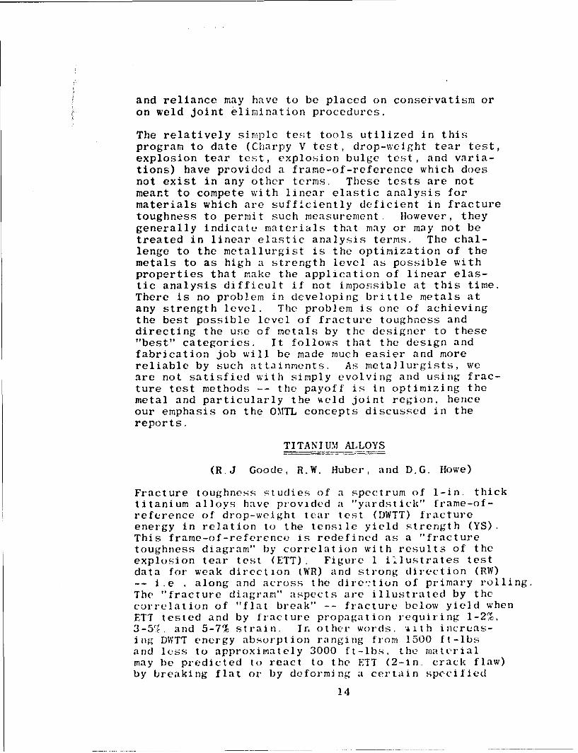
TITANIUM ALLOYS
(R.J Goode, R.W. Huber, and D.G. Howe)
Fracture toughness studies of a spectrum of 1-in. thicktitanium alloys have provided a "yardstick" frame-of-reference of drop-weight tear test (DWTT) fractureenergy in relation to the tensile yield strength (YS).This frame-of-reference is redefined as a "fracturetoughness diagram" by correlation with results of theexplosion tear test (ETT). Figure 1 illustrates testdata for weak direction (WR) and strong direction (RW)-- i.e , along and across the dire-tion of primary rolling.The "fracture diagram" aspects are illustrated by thecorrelation of "flat break" -- fracture below yield whenETT tested and by fracture propagation requiring 1-2%.3-5•,. and 5-7% strain. In other words. .,i t h increas-ing DWTT energy absorption ranging from 1500 ft-lbsand less to approximately 3000 ft-lbs, the materialmay be predicted to react to the ETT (2-in. crack flaw)by breaking flat or by deforming a certain specified
14

amount prior to fracture. The optimum materials trendline (O0MT) marks the maximum (optimum) limnit of thehighe.st DWTT values noted as a function of yield strength.From a reliable prodý,cibility point of view the OM•!Thprobably has to be "shifted back" approximately 10 ksiat any specified level of DVTTT energy. Also, withincreasing thictkness the OMTL may be expected to be"shifted back" -- additional test data are requiredto develop a diagram relating to thick materials,materials subjected to special processing, and forwelds of various thickness. It should be noted thatFig. 1 also presents approximate Charpy V values, re-lated to the DWTT energy. These correlations have notbeen sufficiently precise to provide for the use ofCharpy V definition of the performance in the E'TT. Forthis reason, we favor the use of the DWTT as being amore exact and discriminating test tiethod -- the Charpy Vtest can be used only as a "rough" index. Tests areunderway to establish the plane str,1in fracture tough-i-,uss (Ki) for a number of alloys represented in ý'ig. 1.It is expected that data will be presented in the nextprogress report -- the principal difficulty has been thedetermination of KIc values that can be considered valid.Consideri.ble contention exists as to the proper methodof determining a crack instability point because titaniumalloys apparently do not give a clear indication of a"pop-in" or crack instability. The fracture mechanics,Kic determinations are being conducted with the advisoryassistance of experts in the field.
At the present time, the only reliable compendium offracture diagram data are available only or, terms of theDWTT. An example of the use of these data is provided bythe 2000 ft-lbs index which represents a value whichassures ETT toughness of a mini.,:um of 1-2% strain (1-2%guaranteed and 3-51t expected) prior to fracture. On anOMTL basis it is possible to attain this performance with135 ksi material -- on a practical producibility basisthis performance may bh expected in production at 125 ksi(on the average). If' effects of increased thickness arefactored into this analysis (from known decreases inyield strength with increased thickness) it should be re-liably expected to attain such levels of fracture toigh-ness at 2-in. and probably 3-in. thickness at a guaran-teed minimum of 105 ksi yield strength. This appearsto be a conservative es;timate based on present kno .,' ledge-- additional tests may show that the fracture toughneýss-yield strength minima for purchase specificationscould be relaxed. On the basis of the subject frame-of-reference, one may make other estimates based on higher
15

or lower levels of fracture toughnroz and other levelsof anticipated production controls, he at to heat variablesetc.
Based upon these studies an Interim Guide issued by theU.S. Marine Engineering Laboratory (6) has modified theprevious 21 ft-lb Charpy V at -80OF specification re-quirements for titanium intended for submarine hull con-struction to a 105 ksi minimum YS and a minimum fracturetoughness of 2000 ft-lb DWTT ?nergy. As seen from thefracture toughness diagram (Fig. 1), this level of tough-ness corresponds to an expected development of 3-5%plastic strain prior to fracture propagation in the ETTin the presence of a 2-in. crack-like flaw.
The 1-in. thick plate alloys that have been investigatedwhich fall within these revised specifications are shownin Fig 2 -- this figure does not include the resultsobtained for the material from the special processingprogram underway at Reactive Metals Inc. (RMI), whichare reported in a sepai'ate section of this report. Thedata points were obtaIned from material in the hot-rolledcondition and in various heat treated conditions, depend-ing upon the alloy, and, as can be seen, a number ofalloys are represented. The remaining principal decidingfactor on the usefulness of any of these alloys in theregion of interest as a hull material is dependent uponthe weldability of the material.
It is hopeful that the OMTL can be moved to higher levelsof fracture toughness through introduction of new alloysresulting from alloy development studies and through heattreatment. An example of this is the TA-6A1-3V-lMo alloywhich was made in the vacuum arc skull melting facilitiesat NRL in the form of a 65-lb vacuum arc remelt cast intoa 4 x 7 x12 in. copper chill mold following which a one-half section of the billet was forged and rolled at NRL.The oxygen level is approximately 0.04%, and through heattreatment it has been possible to develop over 4300 ft-lbDWTT energy at a 109 ksi YS level. As seen in Fig. 2,these properties exceed the previously established OMTL.The heat treatment used was annealing at 1675'F for twohours and water quenching, followed by an aging treat-ment. at 1300OF for one hour then air cooling,
EFFECT OF PRUC*ESSIhNG VARIABLES ON STRENGTH AND
TOUGHNESS OF A Ti-7A1-2Cb-lTa ALLOY
A study of processing ',ariables on the mechanical properti
16

of a Ti-7AI-2Cb-lTa alloy (lit 291488) is being conductedby RMI under spon.,sorship of the U.S. Navy Bureau of Shipc.NRL is evaluating thio plate material evolved in this studyin the DWTT and ETT to provide guideline information onthe full plate thickness strength-toughness combinationsdeveloped in relation to the O1MTL for titanium. Someresults were presented previously in the Fifth QuarterlyReport (7) on plate produced by forging and hot rolling.Drop-weight tear test information has been recently ob-tained on extruded plates. The earlier reported resultsare included in this report with more detailed processingand heat treatment information.
The average chemical composition of the alloy as reportedby RMI is:
Weight -
Al Cb Ta Fe C N2 02
6.9 2.5 1.1 0.13 0.01 0.006 0.063
The forging and hot-rolling procedure used by RMI forproducing this 1-in. thick forged-and-rolled platematerial was as follows: Ingots were forged from 24-in.diameter to 4 x 17 x 19-in. Blabs using three differentunspecified forging techniques at a starting temperatureof 2200'F (furnace temperature) and 1820*F finishingtemperature; die temperature was 1980 0 F. The slabs werethen rolled to 1.1-in. thick plate using an 1850*Finitial and 1700'F final rolling temperature. Theeffects of annealing and aging temperatures on thetensile YS and fracture toughness as measured by theCharpy V notch and DWTT are given in Table 1.
The extruded material was produced in the form of bars5 x 1-in. by length, using a 5500-ton press. The ex-trusion temperatures were 1900°F (P extrusion) and1700'F (&+9 extrusion). The billet diameters were10.6-in. and 9-in. for the 1900°F and 1700"F extrusions,respectively. The effects of heat treatment on thestrength and toughness properties are given in Table 2.
Forged-and-Rolled Plate
Within the scope of this investigation several inter-esting general observations can be made from the resultsobtained with the forged-and-hot-rolled plate material.These are:
17

4(1) The effect of processing on the "as-forged"
and hot-rolled fracture toughness properties as deter-mined by the D47TT was greatest in the R17 fracturedirection (8) Here the spread of valves is appro.xi-mately 500 ft-lb, whereas in the WR fracture directionthe spread is about 150 ft-lb. The effect of processing"orn the tensile YS seems to be slightly greater in thetransverse direction than in the longitudinal direction-- 8.5 ksi and 5.5 ksi spread, respectively.
(2) Fracture toughness, as measured by the DVITT,is essentially the same in the R17 and WR directions,independent of processing procedures, when the platesare annealed above the 0 transus regardle.ss of whetherthe annealing treatment is followed by air cooling orwater quenching (except for forging process C). Waterquenching does result in generally lower DWTT energyvalues and higher tensile YS compared to air cooling.
(3) Annealing slightly below the A transus(ot+g field) produces the highest levels of fracturetoughness (DWTT data) compared to either the A annealedor as-forged and hot-rolled plate. The yield strengthsobtained are comparable to those obtained in the as-forged and hot-rolled condition. However, except forforging process A. the spread in DWTT energy for thetwo directions remains the same or is slightly greaterthan that of the forged-and-hot-rolled material.
(4) Annealing the material subjected to theforging process A produced essentially the same DWTTenergies in both the RW and WR orientations regardlessof whether it was an ce±p anneal or 0 anneal followedby air cooling or water quenching. This was probablythe result of the particular forging procedre usedin the initial breakdown of the ingot.
(5) The Charpy V notch test does not provide asatisfactory discrimination of the process variables,as compared to the DWTT.
Specifically, the better combination of strength andtoughness is afforded by the A anneal followed by aircooling, giving approximateiy 2700 ft-lb DWTT energyin the 106-110 YS range. Water quenching followingthis same annealing treatment raised the strength to109-122 ksi range at some expense to the fracturetoughness level.
18.

Extru-;Jonn
The rc:;ults obtaincd with the extruded and heat treatedmaterial suggest the follo7fnLJ general conclusions:
(1) Considerable snisot, opy in fracture toughnessis present in these materials; from the few measure-ments made, the DWTT energies in the R17 direction isapproximately double those in tLe WR direction.
(2) The anisotropy in YS values is not much morethan is normally found in commercially-produced forged-and-rolled plate but, in most instances, the specimenstaken parallel to the extrusion axis had the highervalues than those taken perpendicular to the extrusionaxis. Generally, in rolled plate, even after heattreating, the reverse situation exists in relationto the direction of principal rolling.
(3) Higher fracture toughness levels and possiblyslightly higher strength levels are developed with theheat-treated a+O extrusions (process D) than are developedwith the correspondingly heat-treated 0 (process E)extrusions. The anisotropy in YS may also be a littlegreater in the a+f extruded material.
(4) As with the rolled plate material, theCharpy V (Cv) data are Lot as discriminatory as theDWTT results.
The materials provided from this study have shown with-out exception a better combination of strength and tough-ness (Fig. 3) over that seen in any of the previouslyproduced Ti-7AI-2Cb-lTa or Ti-8A1-2Cb-ITa alloys investi-gated at NRL (Fig. 4). Several of the processing proce-dures coupled with heat treatment for forged-and-rolledplate have produced material which approaches the esti-mated OMTL for titanium. The heat-treated 1700OFextrusions exceed the OMTL when tested in the strong(9W) direction. However, the OMTL represents "rolledplate" weak direction properties, and on this basis theweak (WR) direction fracture toughness properties ofthe extrusions lie considerably below it.
DIFFUSION-BONDED TITANIUM ALLOY PLATES
The notch fracture toughness properties of laminatedplate prepared from diffusion-bonded titanium alloy
19
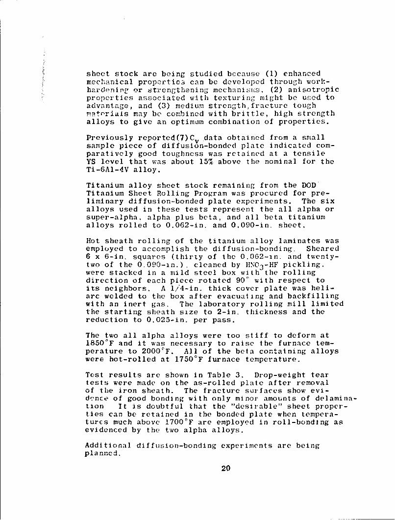
7 sheet stock are being studied because (1) enhancedmechanical propertic3 can be developed through work-
dchardJnln or strengthening mechanii;s, (2) anisotropicproperties associated with texturing might be used toadvantage, and (3) medium strength,fracture tough.iptrials may be combined with brittle, high strengthalloys to give an optimum combination of properties.
Previously reported (7)C. data obtained from a smallsample piece of diffusion-bonded plate indicated com-paratively good toughness was retained at a tensileYS level that was about 15% above the nominal for theTi-6A1-4V alloy.
Titanium alloy sheet stock remaining from the DODTitanium Sheet Rolling Program was procured for pre-liminary diffusion-bonded plate experiments. The sixalloys used in these tests represent the all alpha orsuper-alpha, alpha plus beta, and all beta titaniumalloys rolled to 0.062-in. and 0.090-in. sheet.
Hot sheath rolling of the titanium alloy laminates wasemployed to accomplish the diffusion-bonding. Sheared6 x 6-in. squares (thirty of the 0.062-in. and twenty-two of the 0.090-in.), cleaned by HNC..-HF pickling.were stacked in a mild steel box with the rollingdirection of each piece rotated 900 with respect toits neighbors. A 1/4-in. thick cover plate was heli-arc welded to the box after evacuating and backfillingwith an inert gas. The laboratory rolling mill limitedthe starting sheath size to 2-in, thickness and thereduction to 0.025-in. per pass.
The two all alpha alloys were too stiff to deform at1850OF and it was necessary to raise the furnace tem-perature to 20000F. All of the beta containing alloyswere hot-rolled at 1750°F furnace temperature.
Test results are shown in Table 3. Drop-weight teartests were made on the as-rolled plate after removalof the iron sheath. The fracture surfaces show evi-dence of good bonding with only minor amounts of delamina-tion It is doubtful that the "desirable" sheet proper-ties can be retained in the bonded plate when tempera-turcs much above 1700'F are employed in roll-bonding asevidenced by the two alpha alloys.
Additional diffusion-bonding experiments are beingplanncd.
20

FRACTRlE TOUGl:ESS OF 2-IN.THICK TITANIUM ALLOY FLATES
Drop-weight (vertical drop, lar'ge mnwchina) tear testson 2-in. Ti-7AI-27&• plate using the bracketing technique(Charpy-type pcndulu2i machine limited to 5000 ft-lbcapacity) give a good limit value of 9200 ft-lb. Pre-viously reported D;77T data on 2-in. Ti-7AI-2Cb-lTaplate using the same technique was 7500 ft-lb (7).Further testing has shown that the actual value iscloser to 7300 ft-lb DMWTT energy.
Cross-section size scale up from the 1-in. to the 2-in.DWTT specimen size involves a ratio of about 3.8 in-crease in area; the corresponding ratio of increase infracture tear energy is in the order of 4.7 to 5.These comparisons are to be considered preliminaryand are subject to more exact comparisons in futuretests.
HEAT-TREATMENT STUDIES ON SOME TITANIUM ALLOYS
Heat-treatment studies (7,9,10,11) an a number oftitanium alloys have been continued in order to developinformation on the stability of the alloys and to deter-mine the beat treatmonts which will produce an optimumcombination of strength and toughness.
Beta transus determinations on the alloys Ti-6.5A1-5Zr-lV (T-36), Ti-6A1-2Sn-lMo-lV (T-37), Ti-6A1-4Zr-2Mo(T-55), Ti-6A1-4V-2Sn (T-67), Ti-6Al-4Zr-2Snr..51Mo-.5V(T-68), and Ti-7A1-2.5Wo (T-71) were made as a prelimin-ary step to full scale heat-treatment studies and theresults of these determinations are shown in Figs. 5-10.The beta transus temperatures are shown in Table 4.
The results of solution-annealing and aging treatmentsfor the alloy Ti-8AI-lN•o-lV (T-19) are shown in Table 5.The treatment includes solution-annealing at temperaturesbelow the f transus for one hour in an argon atmospherefollowed by air cooling or water queiiching. The speci-mens were in most cases aged at 1100 OF or 1200OF fortwo hours in an argon atmosphere and water quenched orair cooled.
The data shows that strength of this alloy is relativelyinsensitive to differences in aging treatment if theannealing treatment is followed by air cooling regard-less of annealing temperature. If after the annealing

treatment a faster quench rate is used, rwater quench,then the strength of the material increases with in-creasing annealing temperatures between 1750 0 -1850 0 F.This is been in Fig. 11 which shows the effect ofsolution annnealing temperature, followed by waterquenching or air cooling, on the YS of the materialwhich had been aged for two hours at 1000F and 1200°F,and then air cooled or water quenched.
Figure 12 is a summary of a preliminary survey based onCv energy and YS relationships for the alloy Ti-8A!-lMo-1V (T-19). The line indicates the optimum "weak" direc-tion properties. Earlier DWTT studies showed that thisalloy, heat treated at 1825°F for two hours, then aircooled, absorbed 2500 ft-lb energy before fracturing,indicating an ETT capability in the order of 5% plasticstrain.
Of all the alloys investigated to date in the heat-treating studies, the alloys Ti-8A1-lMo-lV (T-19),Ti-6Al-4Sn-IV (T-20), and Ti-6A1-2Mo (T-22) have shownthe best combinations of Atrength and toughness. How-ever, the properties of welds with some of these alloyswill probably be difficult to maximize both as tostrength and fracture toughness.
ALUMINUM ALLOYS
(R.W. Judy, Jr.)
The testing of aluminum alloys during this period wasconfined to explosion tear testing (ETT). This is alarge scale structural prototype element test whichutilizes explosive loading in the presence of a sharpflaw. The object of the test is the determination ofthe amount of plastic strain which can be developed bya particular alloy in the presence of a sharp 2-in.crack-like flaw. It has been shown that this strainvalue can be related to the drop-weight tear test (DWTT)energy for steels and titanium alloys (9).
The preliminary fracture toughness diagram (Fig. 13)illustrates the results of the testing done to date.The crosshatched lines indicate correlations betweenDWTT energy and the amount of plastic strain that can bedeveloped in the ETT before failure occurs. PreliminaryETT work had indicated that the 750 ft-lb level of DWTTenergy was indicative of approximately 4% allowableplastic strain and that below 300 ft-lb, fracture belowyield strength could be expected (7). However, a
22

6061-T651 (DiVTT - 750 ft-lb) specirien was tested to 7.3%plastic strain (Fig. 14) without cor;ipletely running thefracture, which indicated a capability for plastic strainin excess of 71r at this Di;TT energy level.
In other tests, a 20241-T,4 (DTT - 367 ft-lb) fracturedcompletely at a 3.2'f plastic strain level, which valueplaced it near the ]lower extreme of' the 1-7% band. A2219-T87 specimen (DWTT--281 ft-lb) fractured completelyat 2.1%, plastic s;train and a 7075-T6 (DWTT - 139 ft-lb)specimen shattered and delaminated when loaded to lessthan 1% plastic strain (Fig. 15). Both of these wereconsidered to have fractured near or below yield strengthlevels. It is obvious that the response of aluminumalloys in the ETT follows a distinctly different relation-ship to the DWTT than observed for steels and titaniumalloys. Certainly, the very low DWTT and Charpy valuesof many of these alloys which indicate low fractureresistance for 4teels and titanium do not translateto the same low levels of fracture resistance in theETT. The importance of developing specific correlationsfor various materials is emphasized by these findings.Additional studies are planned for aluminum alloys toevolve more exact relationships. These will includeKIc. plane strain fracture toughness determinations foralloys that provide a valid basis foor measurement atthe specified thickness.
HIGH STRENGTH STEELS
(P.P. Puzak, K.B. Lloyd, and E.A. DeFelice)
High strength steel studies have been continuing to evolvefracture toughness vs. yield strength (YS) frame-of-refer-ence charts in terms of drop-weight tear tests (DWTT) andCharpy V (Cv) tests conducted at 30'F. Correlations withexplosion tear test (ETT) data have served to define theprefracture strain levels similar to those describedpreviously in this report for the case of titanium alloys.The highlights of the studies for steels have been thepronounced effects of melting and rolling process varia-bles on fracture toughness properties for some "new"steels in the 150+ ksi YS range over that of the "old"types. The "old" types are generally characterized asHY-80 compositions heat treated to a range of highstrength levels and the various 4330 - 4340, 11-11, D-6,etc.. as compared to the "new" types characterized by theinaraging, the 9Ni-4Co, 5Ni-Cr-Mo-V, and lip varieties.
23

Additional material is being procured to develop moredetailed data on the effects of process variable.-, forthe Various types of steels.
From thse- studies, it has becornle clear that the frac-ture toughness of steels at a particular strength levelis a critical function, not only of the composition ofthe steel, but also the process history -- data for aparticular analysis and thickness are relatively meaning-less without simultaneous definition of the process prac-tices. It is also necessary to specify the test directionwith respect to the rolling direction. In general, thecharacterization of relative fracture toughness for speci-fied directions and process conditions has evolved as amajor contribution of this program which clarifies anotherwise completely confusing picture of relativefracture toughness quality for a particular composition.In the absence of this information it would not be pos-sible to "index" the quality of a particular steel withrespect to others.
Additional studies are required to ascertain the effectsof increased thickness compared with the 1-in. thicknessfor which most of the data to date have been obtained.In effect, thickness becomes a third dimension to the DINTTand Cv frame-of-reference data in relation to yieldstrength, Future studies will be aimed to evolve signi-ficant information relative to thickness effects, tosimilar explorations of frame-of-reference charts forweld metal,, and to deter-ainations of Kic plane strainfracture toughness at yield strength levels that providefor obtaining meaningful data of this type. In addition,explosion tests of weldments will be required to evaluateheat-affected-zone (HAZ) properties. The weldment studieswill be conducted on selected or "more promising" materials.
A summary of the DWTT results as a function of the yieldstrength of the test material for I-in. thick steel platesis presented in Fig. 16 The curves shown in Fig. 16separate these data into characteristic groups relatingto the processing variables (melting practice and/orcrossrolling) of the steels. It should be noted thatthese data represent the lowest level of fracture toughnessfor the indicated material, i.e., fracture propagationin the "weak" direction of a rolled plate, providing sucha direction exists. Straightaway rolling of a steel plateresults in pronounced "fiber" direction in the plate withrelatively low fracturc toughness in the fiber (longitudi-nal or "weak") direction and significantly higher (3000
24

to 4000 ft-lb) fracture toughness in the "strong"direction. Conventionally processed steel plates fea-ture approximately a 3 - 1 crossrolling ratio and widedifferences in fracture tous1hne1;S can still be obtainedas a function of speci.:pn orientation. Snecial 1 - 1crossrolling results in plates having isotropiJ c (samefracture toughness) properties in the two directions,and the indicated values represent this fact.
For each characteristic group of steels shown inFig. 16, it should be noted that a wide range of frac-ture toughness may be developed by different alloysteels of the same yield strength level; however, themaximum depicted by the curve is seen to indicate thatfracture toughness decreases with increasing strengthlevel for all groups of steels. The limiting ceilingcurves have been designated as the "eptimum" materialstrend line (MTL). The OjMTL may be recognized as the"yardstick" for evaluation of new steels with respectto the practicable upper limits of fracture toughnessfor any given strength level as a function of conven-tional or special processing variables. Of particularinterest is the fact that the limiting, ceiling curvein Fig. 16 depicts the apparent practical uppeor limitsof toughness for any strength level attainable withspecial melt practice and 1 - i crossrolling of thenew alloy steels developed within the past five toseven years. The OMTL indicated for the "old" steelalloys that have long been in use for high strengthapplications (SAE 4340, etc.) represent vacuum consum-able-electrode-remelt (CER) practice and I - 1 cross-rolling. This OMTL indicates better strength andtoughness levels than that developed by conventionallyprocessed steels, but considerably lower levels thanthe OMTL in Fig. 16 for the recently developed newalloys.
The standard method for evaluating fracture toughnessavailable generally to industry has been the Charpy V(Cv) test. Correlations between the DWTT and the Ctest have provided a means of calibrating the signiYi-cance of the standard industry "small specimen" testmeasurement. For the steels studied to date, Fig. 17depicts the relationships between DWTT and Cv tests.It should be emphasized that the surprisingly good cor-relation of DWTT energy values with Cv values applies tosteels studied to date in this program, at least for Cvvalues exceeding 35 ft-lb. A summary of 30OF Cv testsfor steel is presented in Fig. 18 as a function of theyield strength of the test material: The curves in
25

this figure separate these data into characteristicgroups relating to the processing variablesof thesteels similar to that described for the data givenin Fig. 16.
REVIEW OF 5Ni-Cr-Mo-V STEEL DATA
A detailed review has been made of the extensive dataprovided by the United States Steel Corporation'sdevelopment program under the Bureau of Ships 130-150 ksi yield strength hull steel contract. The resultsof this review may be summarized in reference to theC -YS frame-of-reference mister diagram discussed pre-vyously. The solid block areas in the diagram ofFig. 19 encompass the 00 to 30°F test data obtained bythe United States Steel Corporation for I/2-to 4-in.thick plates for the first two large scale productionheats (Nos. X53185 and X53588) of 5Ni-Cr-Mo-V alloysteel. These materials were produced by a high qualityelectric furnace practice employing two oxidizing andone reducing slags, and all final deoxidation and alloyadditions for adjustment of final composition were madein the furnace -- not in the ladle or mold. The effectsof other melting practices and processing variables onthe mechanical and toughness properties of this alloysteel composition are being investigated and will bereviewed in a later quarterly progress report. Thedata shown in Fig. 19 indicate that the first two pro-duction heats resulted in material of high fracture tough-ness, close to the upper OMTL for 1/2 and 1-in. plates.The data for 2-in. and 4-in. plates fell in an inter-mediate position -- it should be emphasized that theframe-of-reference used is that which was developed for1-in. plate data. These comparisons again emphasizetwo aspects of the problem of comparing properties ofa given composition with those of other types -- (1) thestrong effect of melt practice, and (2) the effects ofplate thickness. The chemical compositions of the firsttwo production heats are given in Table 6.
A summary of MIG and stick weld data obtained under thissame contract are represented by the additional dashedblock areas in the diagram of Fig. 19. It should benoted that the properties of 1-in. and 2-in. plates ofheats Nos. 1 and 2 reported by the United States SteelCorporation were checked by NRL and found to be in closeagreement.
EXPLOSION BULGE TESTS OF 5Ni-Cr-Mo-V WELDMENTS
Explosion bulge tests have been conducted for United
26

States Steel Corporation's 5Ni-Cr-Mo-V 1-in. steelplates welded with 140 ksi yield strength MIG weldmetal developed und r the U.S. S. -BuShips contract.General experience with the explosion bulge teststo date has demonstrated that underr-atch ing vwldsresults in a considerable decrease in weldment per-formance, and as such is not desirable for hull ap-plications. A cooperative investigation of thequestion of relative performance of overmatching.--matching -- undermatching; weldments of the new 5Ni-Cr-Mo-V steel was undertaken. Several specimens wereprepared by U.S.S.-Airco for explosion bulge testswith the base-plate steel heat treated to nominalyield strength levels of 130, 140, and 150 ksi andjoined with a MIG weld metal having a nominal yieldstrength of 140 ksi. The weld crown on each specimenwas fully ground smooth and phtogrids vere appliedto the specimens.
Figure 20 illustrates the appearance of three bulgetest specimens (undermatching, top; matching, center;overmatching, bottom) that withstood four explosiveshots (7 lb, 15-in. standoff) with no visible signsof failure. Reliable surface strain measu, ements wereprecluded by deterioration of the photo-grids on thefirst explosive loading of the plates. lHowever,visual examination and a carefully measured profileof each bulge specimen, Fig. 21, provided evidenceconfirmng previous experience concerning relativeperformance of under'matching -- matching -- ovler-matching weldments. In each specimen, the heat-affected-zone (1IAZ) was found to be in relief indi-cating greater straining in unaffected plate materialthan in the HAZ. Even though the weld was not cen-trally located in the undermatch weldment sample,this weld metal was visibly strained more than theothers, and a depression or ridge approximately lO-milsdeep had formed in the center of the weld. Past ex-plosion bulge test experience has indicated that ifthe weld crown is not ground smooth, the strain con-centration at the toe of undermatch welds tends topromote complete separation of the b Ige test ;peci-men on the first or second explosive shot.
These tests were primarily aimed at defining therelative strain conditions in mismatched weldments.Additional tests with weld reinforcement and withcomplex weldment assemblies would be required to judgethe relative suitability of matched and undermatched
27

welds. Equally important, it is essential that testsbe conducted with flaws (such as crack-starter weldcracks) located in weld and HtAZ rcgions. It is im-portant to develop a "failure" of the weld zones todetermine if this is of high or low fracture toughness.For example, a complete fracture following a weld or1IAZ path, as compared to a short fracture resistanttear, has the same meaning as for plate tests. Ex-plosion bulge tests of flaw-free weldments do not provideinformation of fracture toughness of weld and 1HAZ regions-- no more so than tests of flaw-free plates.
The samples shown in Fig. 20 will be subjected to addi-tional explosion tests to develop failure -- from whichthe extent of fracture resistance can be evaluated.Additional tests will be conducted with new weldmentsfeaturing flaws. In addition, fatigue data should beobtained for undermatching welds.
FRACTURE TOUGHNESS CNARACTERISTICS
OF A NICKEL-BERYLLIUM ALLOY
(R.J. Goode, R.W. Judy, Jr.:, Wand Rý.,W. Huber)
Recently, two 1-in. thick plate specimens of BerylcoNickel 440 -- a nickel-2% beryllium alloy -- were ob-tained from the Beryllium Corporation for preliminaryevaluation as a distinctly"different" material and there-fore of interest in relation to the development of frac-ture test correlations. The nominal composition of thismaterial is 1.95 Be, 0.5 Ti, and the remainder Ni.
A series of small laboratory tests, including the drop-weight tear test (DWTT), the tensile test, and ZheCharpy V (Cv) notch test, were conducted on the twospecimens; one of these being in the annealed condition,and the other in the full-hardened condition. The DWTTspecimens were 5-in. wide, 1-in. thick, and 17-in. long(the standard geometry for titanium and aluminum speci-mens) with the direction of principal rolling in the5-in. dimension. Titanium was used to embrittle theelectron beam crack-starter weld (9). This is the sametechnique described previously for the introduction ofa brittle zone in titanium alloys for which iron wire isused as a contaminant. All DWT tests were conducted inthe WR orientation (8).
28

In the annealed condition, the energy values obtainedfrom the fracture toughncss tests (DU:TT and Cv) exceededthe rating of the respective testinfr rit~chines;. In theDWTT, 5000 ft-lb of energy was absorbed by the spc,.cirFenat 30°F with the resultin,-;, crack produced by the brittleweld extending approximately one inch into the testmaterial. The specimen was broken at -410F for studyof the fracture surface in the electron microscope.Even at this temperature the specimen required two blowsfor complete fracturing, one consuming 5000 ft-lb andthe second consuming 3950 ft-lb for a total of 13,950ft-lb for complete fracture of the annealed DWTT speci-men. This shows an extremely high level of fracturetoughness. Standard Cv specimens cut from the annealedDWTT specimen were tested in a 264 ft-lb Tinius Olsenmachine with the res•ult that none of the specimens wouldbreak, even at liquid nitrogen temperature. Figure 22shows the deformed specimens tested at -320'F. Thetensile strength of the annealed specimen was 47.8 ksi;the ultimate tensile strength was lO0 ksi.
The initial DWTT energy value obtained for a specimensolution-treated to the full hard condition was about1840 ft-lb. Further substantiating DW'VT tests wereunsuccessful due to failure in the welds used to joinsteel tabs onto the specimen to provide the properspecimen span for testing. The full hard conditionof the specimen was developed by heat treating for1-1/2 hours at 970"F during which precipitation harden-ing occurred. The crack-starter welds and tab weldswere incorporated in the specimen after heat treatment.The Cv tests were conducted on specimens with the resultthat the Cv energy values were essentially constant at15 ft-lb (RW) and 12 ft-lb (WR) over the -320'F to212cF temperature range (Fig. 23). Yield strength inthe full hard condition was 177.5 ksi; the ultimatetensile strength was 242.5 ksi.
The fracture surfaces of the DWTT specimens were examinedin the electron microscope. Figures 24 and 25 show com-parable areas of t!. fracturc surfaces of the annealedspecimen and the full hard specimen, respectively. Inboth cases, fracturing occurred primarily by the sameductile mode; however, considerable differences in thetwo fractographs can be seen. In Fig. 24, the failuremode was by dimpled rupture (12) with gross plasticdeformation in evidence. The dimples were very largeand deformed by stretching and serpentine glide (12).
29

The full hard specimcn also failed by dimpled rupture(Fig. 25), but the diiýples were considerably smallerthan those seen in the annealed speciren, and verylittle evidence of plastic deformation of the dimpleswas in evidence. The differences in appearancedescribed indicate a difference in plastic strainimparted to the specim:en during the fracture; thissame factor probably accounts for a large portionof the gross differences in the fracture toughnessenergy values found in the DWT and Cv tests.
The two heat treatments used in this study representto some degree two extreme combinations of strengthand fracture toughness. Since combinations of strengthand fracture toughness lying between these values areattainable by proper heat treatments and could com-pare very favorably with structural materials now beingstudied, a more thorough investigation of the propertiesof this alloy and related alloys could be of interest.
NEW LABORATORY DROP-WEIGHT
BULGE TESTING FACILITY
(R.J. Goode, E.A. Lange, and P.P. Puzak)
Reliable knowledge concerning weldment performance isessential to fracture-safe design of structures fabri-cated with high strength steel, titanium, and aluminumalloys. The problem with these high strength materialsis the potential susceptibility to develop low energy-absorption tear fractures, particularly in the heat-affected-zone (HAZ) regions of weldments. Such sus-ceptibilities may not be inherent to the mill producedmaterials, but may be developed in response to specificmetallurgical treatments on weld fabrication in theHAZ regions. One example of a catastrophic low energytear failure in which the initiation and propagationof the terminal fracture were uniquely associated withthe HAZ regions of a "lean-analysis", quenched andtempered (Q&T) steel pressure vessel has been fullydocumented (13,14)
The NRL explosion bulge test developed in 1949-50 hasbeen the only reliable test method for evaluating thepotentials of heat-affected-zone (HAZ) fractures inthick plate weldments. The method has been used by theNavy for the past fifteen years to preclude the use insubmarine hulls of Q&T steel weldments with low energy
30

tear (or brittle) fracture proporties in the "AZ. TheNAVS1IPS Standard (250-,637-G) proccdure dorived fromthese studies relies not only on p-rforr '.nce exhibitedby as- woldod sab les, but 1 on '.. to whicha crack-starter bLad is adced. T' crac,-.....e baad - c ra c,, ta, rtecr b e ad
introduces a brittle wcld-crack flaw providing., arealistic structural flaw condition. The fracturetoughness of the ILXZ is then Judged on the extent ofHAZ tearing which results from the application of lowor high levels of bulge deformation. In addition tothe Navy test facilities, several commercial bulge testfacilities have been established uithin the past fiveyears.
Within the past decade, the most versatile and valuablelaboratory tool for evaluating the fracture toughnessof prime plate and weld metal has proved to be thesimple drop-weight test machine. Since there were nopractical laboratory means for evaluating fracturetoughness Tof z, a feasibility study was conductedwith an existing one-ton drop-weight machine and 1/2-in.thick steel weldmentn. Upon the successful completionof this study, a large drop-weight test facility(Fig. 2G) was designed, constructed, and placed inoperation. The capacity of the machine is 240,000 ft-lbwhich is obtained by dropping a 6-ton weight a distanceof 20 feet. This new test facility will provide alaboratory means of conducting HAZ fracture toughnessevaluations of 1, 2, and possibly 3-in. thick aluminumand titanium alloy weldments of up to 160 ksi yieldstrength levels, and 1 and possibly 2-in. thick steelweldments of 150 to 180 ksi yield strength levels.
The drop-weight bulge test procedure entails the useof an expendable aluminum "punch" casting. Its generalshape is that of a right truncated cone with a basediameter of 5-in. A hardened T-shaped steel pin de-signed to cover the top diameter of the casting andfit snugly in a 2-in. deep hole is used to transmit thedrop-wc&ght loading to the soft aluminum casting. Theresulting deformation developed by drop-weight loadingof the assembly forms a hemispherical bulge of theweldment as it is forced into the open cavity of a die.
One-inch thick prime plate specimens of 150 ksi yieldstrength steels were used for the initial correlationof results with the new drop-weight machine and thestandard explosion bulge test. The surface strains(bulges) developed by one full-capacity drop-weight
31

test with the new machine wvere slightly greater thanthose developed in other spocim•ns of the same steelsby one seven-pound Pentolite charge exploded at a15-in. standoff (Fig. 27). Using the sarine aluminumcasting and pin as;sembly and three blows at full-capacity,the average surface strain was approximately twice thatin another specimen of the same steel subjected to threeexplosive loadings of seven-pound charges at 15-in.standoff. The shape and geometry of the casting areeasy to cast in a foundry, and used castings can beremelted to provide material for new castings.
The use ol this equipment will be expanded followingadditional correlations with explosion tests -- duplicatewelded specimens are to be tested in explos-Lon and drop-weight. It is also planned to modify the aluminum blockto provide for simulated explosion tear tests. For thispurpose, a cylini'ical surface is developed by the useof a "shoe-like" aluminum block which deforms into acylindrical surface on deformation loading.
LOW CYCLE FATIGUE CRACK PROPAGATYON STUDIES
OF Ti-6AI-4V, Ti-7A1-2Cb-!Ta, AND UNALLOYED TITANIUM
(T.W. Crooker, R.E. Morey, and E.A. Lange)
The safe and dependable application of modern high strengthmaterials to large cyclically-loaded structures, such aspressure vessels and submersible vehicles, requires animproved knowledge of slow crack propagation resultingfrom low cycle fatigue. Small flaws and cracks invariablyare formed during fabrication and manufacture of a largewelded structure, despite the use of the best availableprocessing and inspection techniques. Since fabricationflaws are unavoidable, the only practical recourse is toprovide design c-iteria for preventing the growth of suchcracks to a critical size from repeated service loads.
The aim of this investigation is to define and evaluatethe factors which control the growth of cracks under lowcycle fatigue conditions. The results of the currentphase of this investigation are based on studies of crackpropagation in center-notched plate bend specimens loadedin cantilever fashion. Preliminary evaluations of thelow cycle fatigue characteristics of a variety of quenchedand tempered steels, Alonel Ni-Cu alloys,andSh2024 aluminumalloy, have been made (7,9,10,15,16). Briefly, it hasbeen observed that for a specific environment and strain
32

ratio, the growth rate of a low cycle fatigue crack isdependent upon applied total strain range, as expressedby the relationship
/ -K(- IT)n where:
L = total length of fatigue crack
N = cycle of loading-
K = constant
cr = total strain rarge
n= exponent
This relationship remains valid in the presence of meanstrains other than zero and in the presence of aqueouscorrosive environments. However, it has been observedthat both of these factors affect crack growth rate.Mean strain can either accelerate or retard crack growthrate, depending upon whether it is tensile or compres-sive. Corrosive environments tend to accelerate crackgrowth rate, depend±ng upon such factors as corrosionresistance, stress corrosion, and hydrogen embrittlement.
MATERIALS AND PROCEDURE
The materials considered in this report are three titaniumalloys; two samples of Ti-6A1-4V (T-5 and T-27), onesample of Ti-7A1-2Cb-lTa (TA-2), and one sample of unal-loyed titanium (T-16). Chemical compositions and mechani-cal properties of these materials are shown in Tables 7through 9. This assortment of titanium structural alloysoffers a wide spectrum of variations in chemistry,strength level, and fracture toughness for comparisonsof fatigue performance. The strain deflection character-istics of these materials in the plate bend specimen areshown in Fig. 28.
The experimental procedure employed for this series oftests is the same as that described in Refs. 7,9,10,15,and 16. Experimental data arebased on the observedmacroscopic growth of fatigue cracks across the surfaceof center-notched plate specimens. These specimens arecantilever loaded under fully-reversed cycling in bothair and 3.5% salt water environments. Constant totalstrain range loading conditions are maintained by ad-justing deflection, and the corresponding crack growthrate is measured. Nominal surface strains are measuredwith electrical resistance strain gages. Each specimen is
33

successively tested at a s.--ccific total strain rangevalue for an interval of several hundred to severalthousand cycles until thc crack growth rate can be estab-::lished, and then loaded to a higher strain level. Inthis manner, a series of crach growth rate versus totalstrain range data pointe :.,re obtained froli each specimeri.For tests conducted under a salt water environ:ment, acorrosion cell is added to the specinen, allowing thesalt water solution to flow over the crack from areservoir during testing.
STRAIN RANGE EFFECTS
Crack growth rate versus total strain range data foreach of the materials in air are shown in Fig. 29. Itcan be seen that the data fall into two distinct groupswhich can be expressed as suparate mathematicAl rela-tionships of the form tL/IL = K((T)n. The unalloyedtitanium data form one relationship with a slope of4:1 and data from the three high strength titaniumalloys form another relationship with a much steeperslope of approximately 8:1.
The slope of these lines is an indication of the sensi-tivity nf the macroscopic crack growth rate to changesin applied strain. Such changes in strain would occurin the presence of a growing crack under constant loadconditions or would result from accidental overload.Thus, materials showing a steep slope possess lesserability to accommodate excursions beyond nominal designstresses without grossly increasing the cyclic crackgrowth rate.
Similar variations in the slope of such curves, i.e.,increase in sensitivity to strain with higher strengthmaterials, have been observed in other alloy groups,specifically Monel alloys (16). Such variations appearto be dependent upon microstructure and this possibil-ity is discussed in Ref. 17. The apparent rapid increasein the macroscopic crack growth rate of high strengthalloys at higher strain values may be due to precrackingof secondary phase constituents ahead of the crack frontin the primary matrix. However, confirmation of thistheory will have to await further investigation of awider variety of materials and a study of the fracturesurfaces.
34
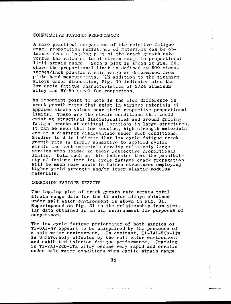
COIMARATIVE FATIGUE PERFOREMANCE
A more practical co:rparison of the relative fatiguecrach propa.gation rcsisttanc.• of materials can be ob-taincd from a log-log pl-+t of the craci growth rateversus:. thzŽ ratio of total strain range to proportionallimit strain range. Such a plot is shown in Fig. 30,where the proportional limit is defined as 500 micro-inches/inch plastic strain range as determined fromplate bend measuremients. In ad-dition to the titaniumalloys under discussion, Fig. 30 indicates also thelow cycle fatigue characteristics of 2024 aluminumalloy and HY-80 steel for comparison.
An important point to note is the wide difference incrack growth rates that exist in various materials atapplied strain values near their respective proportionallimits. These are the strain conditions that wouldexist at structural discontinuities and around growingfatigue cracks at critical locations in large structures.It can be seen that low modulus, high streagth materialsare at a distinct disadvantage under such conditionk-.Studies to date indicate that low cycle fatigue crackgrowth rate is highly sensitive to applied cyclicstrain and such materials develop relatively largestrains when loaded to their respective proportionallimits. Data such as this indicates that the possibil-ity of failure from low cycle fatigue crack propagationwill be much more acute in future structures employinghigher yield strength and/or lower elastic modulusmaterials.
CORROSION FATIGUE EFFECTS
The log-log plot of crack growth rate versus totalstrain range data for the titanium alloys obtainedunder salt water environment is shown in Fig. 31.Superimposed on Fig. 31 is the relationship from simi-lar data obtained in an air environment for purposes,6fcomparison.
The low cycle fatigue performance of both samples ofTi-6A1-4V appears to be unimpaired by the presence ofa salt water environment. In contrast, Ti-7A1-2Cb-lTais unfavorably affected by the salt water environmentand exhibited inferior fatigue performance. Crackingin Ti-7A1-2Cb-lTa alloy became very rapid and erraticunder salt water conditions when cyclic strain range
35

values exceeding approximately C0% of the proportionallimit were applied. Figure 31 shorws that significantacceleration in the growth rate c:ists at all strainlevels in Ti-7A1-2Cb-lTa; ho-iewc.r, r L value of 10%of the proportional limit (10 ,•CC c;ro c-o-inchoes/inch)appeared to be a threshold valuo b1;yond which a formiof"corrosion cracking" appeared to be the dominantcrack growth mechanism. These fatigue data suggestthat a corrosion problem may very well exist in thestructural application of Ti-7A1-2Cb-ITa alloy, atleast for structures containing flaws.
CONCLUSIONS
(1) Macroscopic growth rates of low cycle fatiguecracks in unalloyed titanium, Ti-6A1-4V, and Ti-7A1-2Cb-lTa follow exponential, strain dependent relation-ships of the form 4L/6N = K(ET)n.
(2) Growth rates in Ti-6A1-4V and Ti-7A1-2Cb-lTa are highly sensitive to small changes in appliedstrain and develop very rapid crack growth rates(>1000 micro-inches/cycle) at cyclic strain levelsbelow the proportional limit.
(3) The presence of a salt water environmenthad no measurable effect on the fatigue crack growthperformance of Ti-6A1-4V. However, Ti-7A1-2Cb-lTaexhibited markedly inferior fatigue crack growth per-formance under salt water conditions at cyclic strainlevels in excess of 60% of the proportional limit.
TITANIUM CASTINGS
(E.J. Chapin)
It is planned to conduct a survey of fracture proper-ties of titanium castings at a future date. In prepara-tion for this future study (to include 100-lb castingsproduced at NRL as a start and hopefully larger castingsto be procured under the Bureau of Ships contracts tofollow at a later date),a brief review was made of ti-tanium casting status. Because of the general interestthis information is presented in the present progressreport. It should be noted that similar questions offoundry producibility problems may develop for othermaterials of competing strength-density ratio.
36

The reactive nature of molten titanium toward atmoý-•p~lril gner: and toward all known refractory materialsconstitut. a major problem in melting and casting ofthe metal. Since the retal can be seriou,1,..ly contami•i..
i;e in tVX, i rocc.;ss., the rmetallurgy of re]ting andcasting, m2:,t Le res;tr~cted to environ t, procees,material. anid equip,:ent that do not affect initialmetal quality. This requirement makes the casting oftitanium a relatively costly operation and limits theuse of titanium castings to applications where forgingproduction rmay involve other problems, particularlywith respect to complexity.
The production of ingot titanium material for subse-quent reduction to fabricated forms differs from theproduction of titanium castings. Ingots are producedby arc melting a consumable electrode in a cold moldin which a shallow molten pool is maintained that isprogressively solidified until the desired length ofingot is obtained. In this process only a relativelysmall amount of metal is molten at any given time.The casting of titanium into desired shapes however,requires that a sufficiently large volume of moltenmetal be accumulated and poured at one time to fillthe required rmold cavities. This requirement makesthe problems of scaling-up melting capacity for in-creased sizes of castings far rore formidable thanthose involving the scaling-up of melting capacityfor production of larger sizes of ingots.
An essential requirement in the successful use ofnonmetallic refractory mold materials for casting oftitanium into desired shapes is that the molten metalmust not wet the mold surfaces and the metal mustfreeze and cool relatively rapidly to avoid harmfulsurface contamination. The solidification time fora given section of the casting must not exceed acertain critical value if contamination or moldbreakdown is to be avoided. This value dependssolely upon the stability of the refractory moldmaterial and the length of time the mold surface isin contact with molten metal. In the case of castlngvery heavy sections, involving increased periods ofsolidification, special precautions must be taken tokeep the mold surfaces relatively cool to avoid con-tamination of the casting surfaces.
The melting procedure in present use for productionof titanium castings consists of arc melting in vacuum
37

one or more consumable electrodes in a water cooledcopper crucible. Rapid melting occurs from the useof high current densities and a large volume of moltenmetal is produced with only a ielatively thin skull ofsolidified titanium being formed at the copper cruci-ble-r-elt interface. The solidified skull remainingin thp crucible after pouring represents about 35% ofthe total rpetal charged.
It is rather difficult to retain adequate amounts ofsuperheat in the melt to assure fluidity because ofsevere heat losses. These include: (1) continuousheat loss from the hottest region under the arcthrough the liquid and the solid skull into the watercooled crucible, and (2) radiation losses from thearc and from the surface of the melt. The amount ofsuperheat that can be retained in a molten titaniumbath for a given power input is therefore low fortwo reasons: (1) there is a limit to the amount ofheat that can be transferred through the molten bath-- the steep temperature gradients rapidly dissipatewhen the arc is extinguished prior to pouring, and(2) the molten bath tends to approach an equilibriumcondition with the skull which means that pouringmust be done very quickly to avoid loss of fluidity.
The amount of superheat in a mclt cannot be determinedaccurately because of the lack of a suitable method formeasuring temperatures of a titanium melt under theconditions of the melting process. As a result it isnot possible to establish optimum pouring temperaturesfor casting and the temperature conditions can onlybe roughly estimated from either the power consumedafter the titanium is completely melted or from opti-cal pyrometer measurements. This circumstance makesit necessary to rely upon trial and error for obtain-ing the necessary fluidity to meet a specific castingrequirement. As a result, the physical and mechani-cal properties may vary considerably between castingsfrom different heats of metal. It is obvious that amethod is needed for determining the temperiture oftitanium melts with reasonable accuracy in order toproduce castings of uniform quality and properties.
Graphite has been found to be the most reliable moldmaterial for casting titanium. Although graphite isnot entirely inert to molten titanium, the carbon con-tamination i', mostly confined to the surfaces of cast-ings while only a very minor amount is added to the
3S

composition of the rietal. The limited reaction oc-curring between rolten titanium and th? cold graphitemold is attributable to the fact that under the con-ditions of casting,molten titanium dces not wet graphiteand the high tF,'risal conductivity of the graphitecauses solidification of a thin skin of metal alm-ostimmediately upon contact at the interface. This cir-cumstance inhibits any large talke up of carbon intosolution in the bulk of the titanium.
Two forms of graphite molds have been developed whichinclude machind graphite and expendable rammed graph-ite. Machined graphite produces surface carbon con-tamination in castings which is generally no greaterthan .01-in. deep. This type of mold, however, hassome disadvantages such as: impermeability to gases;it is costly to make; it has short life; and it isnot suitable for castings of complex geometry. Asecond type of mold that was developed to overcomesome of the disadvantages of machined graphite con-sists of a graphitic material composed of a combina-tion of graphite powder and carbonaceous additivesused to prepare expendable rammed molds on a patternusing conventional foundry techniques. The expend-able graphite material can be used for internal coresin castings and such cores can be readily knocked outof the castings. Castings produced in this type ofmold are comparable in surface finish and soundnessof castings produced in machined graphite, however,the depth of carbon contamination is greater, amount-ing to about .04-in. maximum for a 1-in. thick section.The advantages of this type of mold include: improvedpermeability; ability to handle complex casting geome-try; and lower mold cost. A characteristic common toboth machined graphite and expendable rammed graphitetype molds is the high thermal conductivity of themold material which introduces shrinkage problemsthat involve production of gross porosity and center-'line shrinkage defects. The extent to which surfacecontamination of castings by carbon impairs ductilityis a question that needs to be resolved by servicetests. In cases where such contamination is coi~sidereddeleterious, the surface contamination is removed tosome predetermined depth by either sandblasting orchemical milling.
Metallic molds composed of copper or of iron are some-
times used for casting titanium where casting geometry
39

permits unrestricted contraction. The high tflrmal con-ductivity of the metallic molds causes rapid freezingof the casting and avoids reaction of the mold with thecasting. This is particularly advantageous in the caseof heavy sections although rapid chilling aggravatesthe shrinkage problems.
Titanium alloys may be cast centrifugally or statically.In general, both processes utilize the same melting andmold technology; the only difference is that in the cen-trifugal mode of casting the mold is spun about a ver-tical axis. This procedure is best suited for produc-tion of cylindrical shapes. Parts cast by this methodhave a considerably finer grain size than staticallycast parts and are easier to machine.
Unalloyed titanium casts readily into relatively com-plex shapes with good surface finish, soundness andgood reproduction of details. Alpha and alpha-betaalloys appear to have a good castability as unalloyedtitanium. Meta-stable beta alloys appear to be diffi-cult to cast because of their long freezing ranges.Consequently, control of shrinkage is difficult due tothe poor feeding characteristics.
The development of titanium alloys with good mechani-cal properties has been almost entirely concerned withwrought material. These alloys are not necessarilygood casting alloys and much of the experimental datathat has been obtained in the development of wroughttitanium alloys may not be directly applicable tocasting alloys. Although a great number of experimentalalloys have been cast, the alloys on which the mostproperty data have been developed include only one alphatype (Ti-5Al-2.5Sn), and one alpha-beta type (Ti-6A1-4V).
Although alpha-beta alloys respond to strengthening byquenching from temperatures above the beta transus,the preferred treatment is to employ a solution treat-ment followed by aging. Alpha-beta alloys are strongerthan alpha alloys on a strength-to-weight ratio basis,however, they suffer from limited weldability. It isdoubtful that weldable alpha-beta alloys can be satis-factorily strengthened by heat treatment in thick sec-tions since weldable alloys with low beta stabilizercontent require very rapid quenching from solutiontreatment temperatures to achieve heat treatmentresponse. The required rapid cooling would be very
40

difficult to obtain in thick cast sections. Where re-quiremonts involve high strength and/or greater ductilityfor heavy section castings, special casting alloys mayhave to <;, developed to mieet these requiremionts.
Present : ndustrial casting furnace capacity perrmitscasting of titanium alloy shapes with maximum dimensionsof 54-in. diameter by 31-in. height and a maximum weightof 400 lbs. ,Metal needed in the casting furnace in theform of consumable electrodes is produced in 204n.diame-ter ingots. Titanium alloys are cast by centrifugal,centrifuge or static methods, depending upon size,shape and requirements. Present centrifugally castbar capability is 8-in. I.D. by 6 ft. length or 24-in.diameter by 30-in. length. Casting yield is about40% of total metal charged.
The carbon content of commercial titanium alloy castingsmade in machined graphite is about 800 ppm maximuxm andabout 2000 ppm maximum for castings made in expendablerammed graphite molds. The surface finish of castingsproduced in these molds is comparable to smooth sandcast finishes. Casting., can meet all classes of X-rayquality dependirg upon design, and pressure tightnessis classified as excellent. Where defects occur dueto gross porosity and centerline shrinkage, the defectsare repaired by a weld repair method. This consists ofdrilling the casting to the defect and filling thecavity with weld metal.
Present melting and casting capacity for producingshaped castings could be scaled up, using presenttechnology to melt 3500 lbs. of titanium alloy materialfrom which a casting yield of 2500 lbs. could be ob-tained using either a static or centrifugal mode ofcasting. The scaled up furnace equipment would ac-commodate shapes up to 12 ft. diameter by 6 ft. height.
Since the production of large thick flat plate bycasting into molds is considered to be not feasiblebecause shrinkage defects cannot be satisfactorilycontrolled by risering, the increased melting andcasting capacity mentioned above would be only for theproduction of shaped castings in gra'hitic type molds.Shaped castings could be scaled up in size and -weightto the limits indicated above without involving anyextensive developmental work in the matter of meltingand casting furnace equipment or in the preparationof molds, providing graphitic type materials would beacceptable for rm~lds.
41

As was discussed previously, it is not known whether
satisfactory wrought titanium alloys would be directlyapplicable for use as casting alloys. Thus, theproblem of obtaining satisfactory casting alloyswhich are weldable and which can be satisfactorilystrengthened in heavy section needs to be investigatedand the mechanical properties of cast and wroughtforms of the same alloy compared.
MODIFIED CIARPY TESTING PROCEDURES:
THE FATIGUE CRACKED CHARPY AND SIDE NOTCHED
CHARPY IN IMPACT AND SLOW BEND TESTING
(L.J. McGeady)
Because of long experience with the use of the conven-tional Charpy V test for carbon steels, most of theinterrelations of results from various specimen typesand test methods are rather fully understood or docu-mented as a result of the sharp transition from toughto brittle failure. Consequently, specification forthese steels can usually be drawn with a remarkabledegree of confidence and precision. The newer steelsdo not, in general, exhibit this sharp transition.Therefore, as they develop, they need to be examinedclosely to determine whether the testing results fromvarious tests and specimens are interrelatable.
More pertinently, the relevance and applicability oflaboratory tests to service behavior need to beevaluated with circumspection and need to be based onthe best experience available. The NRL drop-weighttear test and modifications offer specimen type andbehavior on a geometric scale large enough to beconsidered prototype. The conventional Charpy V-notched specimen offers different characteristics insize and possibly test response. It is importantto know whether the Charpy test can be correlatedwith the larger test. Recently it has been demon-strated at NRL that there is a high degree of cor-relation possible between the drop-weight tear testmeasurement of steel notch toughness at 30'F andstandard Charpy test shelf energy measurements. Ithas been suggested that improve- correlation of results
42
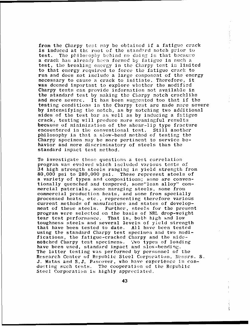
from the Charpy test may be obtained if a fatigue crackis induced at the root of the standord notch prior totest. The philopopny bohind so doing Is that becausea crack has already been formed by fatigue in such atest, the breaking energy in the Charpy test is limitedto that energy required to force the fatigue crack torun and does not include a large component of the energynecessary to cause a crack to initiate. Therefore, itwas deemed important to explore whether the modifiedCharpy tests can provide information not available inthe standard test by making the Charpy notch cracklikeand more severe. It has been suggested too that if thetesting conditions in the Charpy test are made more severeby intensifying the notch, as by notching two additionalsides of the test bar as well as by inducing a fatiguecrack, testing will produce more meaningful resultsbecause of minimization of the shear-lip type fractureencountered in the conventional test. Still anotherphilosophy is that a slow-bend method of testing theCharpy specimen may be more pertinent to service be-havior and more discriminatory of steels than thestandard impact test method.
To investigate these questions a test correlationprogram was evolved which included various tests of34 high strength steels ranging in yield strength from80,000 psi to 280,000 psi. These represent steels ofa variety of types and compositions; some are conven-tionally quenched and tempered, some"lean alloy" com-mercial pnaterials, some maraging steels, some fromcommercial production heats, and some from speciallyprocessed heats, etc., representing therefore variouscurrent methods of manufacture and states of develop-ment of these steels. Further, steels for the presentprogram were selected on the basis of NRL drop-weighttear test performance. That is, both high and lowtoughness steels and several levels of yield strengththat have been tested to date. All have been testedusing the standard Charpy test specimen and two modi-fications, the fatigue-cracked Charpy and the side-notched Charpy test specimens. 'A'wo types of loadinghave been used, standard impact and slow-bending.The latter testing was performed by personnel of theResearch Center of Republic Steel Corporation, Messrs. S.J. Matas and S.J. Pascover, who have experiOnce in con-ducting such tests. The cooperation of the RepublicSteel Corporation is highly appreciated.
43

Figures 32 and 33 illustrate the correlations determinedbetween rcsults from conventional Charpy tests andresults from rodified specimens and procedures. TheW/A rcults have been used as the basis for plottingthe figures, to take into account the cross-sectionalarea of specimen broken since this varies between thespecimen types. Figure 32 portrays the correlationof results from conventionally notched and testedspecimens with results of impact tests of fatiguecracked specimens and also with results of tests ofspecimens side notched and fatigue cracked. Figure 33illustrates the relation of conventional impact testresults to slow bend test results of modified Charpytests. Although there is considerably more scattershown in Fig. 33, some of the scatter may be due tothe fact that specimens for some of the steels weretested in slow bending at 90'F while other steelspecimens were tested at 30 0 F.
The energy absorbed in fracturing specimens can bereported in terms of W/A, work or energy expended perunit area of fractu:e surface produced. This systemhas been used in analysis of the data from this testprogram. However, since the W/A values are merely themeasured ft-lbs energy absorbed in the Charpy testdivided by a constant, use of this figure in itselfdoes not reveal anything not already available fromthe test data from which it is derived.
The principal effect of intensifying the standardCharpy V notch, by addition of a fatigue crack aloneor by addition of a fatigue crack and side notchescombined, is to cause less energy absorption in speci-men fracture. The effect has been shown to be pre-dictable and to be independent of the type of steelused in these tests. When the steels tested wereranked in decreasing order of toughness (Fig. 34)using as a basis either the conventional Charpy testresults or the results from modified specimens, theorderings with minor exception were the same irrespectiveof the test specimen used. The most serious exceptionto this occurred in the results of slow bend testswherein the instance of five steels 4/A and/or Evalues of side notched specimens were higher thanthose of corresponding steels fatigue cracked only.
44

This may have occurred becazu:e sorme of the specimenstested in slow bonding were terted zt 9O0 F while othkrSwere tested at 30 0 F.
The data obtained by slowv b,=ndinP,,, of the modifiedCharpy test specimens are chracterized by considerrahloscatter. However, average results of energy absorptionin the slow bend tests correlate reasonably well withvalues obtained in conventional impact testing of ttosame steels.
In addition to not being of particular advanta-e, theuse of the notching procedures r,.more severe than in the,conventional Charpy tests caus;es a reduction of loxvalues of energy absorption for all steels such thatease of discrimination among the steels is seriouslyreduced for the lower levels of energy absorption.
It is likely that if all specimens had been tested at30 0 F, the correlations obtained between slow bend testsand conventional impact tests would have been evencloser. However, despite this feature of the testirngprogram, the correlation lines of Figures 32 and1 33are identical. This is further substantiation thatthe results of the modified tests can be predictedwith reasonable accuracy from the conventional Charpytest results. Hence the value and necessity of modi-fied Charpy testing procedures appear questionable.
45

REFERENCES
1. Pellini, V.S., and FPzak, P.P. , "Fracture AnalysisDiagraz.i Procedurcs for the Fi'acture-Sa fe Engineer-ing Dcsign of Steel Structures," NF1L Report 5920,March 15, 1963, and Welding Research CouncilBulletin Series No. 88, May 1963
2. Pellini, W.S., and Puzak, P.P., "Practical Con-siderations in Applying Laboratory Fracture TestCriteria to the Fracture-Safe Design of PressureVessels," NRL Report 6030, Nov 5, 1963t alsoTrans. of the ASME, Series A, Journal of Engineer-ing for Pov~er, Oct i964, pp 429-443
3. Brown, et al, "Interim Report of Progress onMarine Corrosion Studies," NhRL Memo Report 1549,July 1, 1964
4. Brown, et al, "Marine Corrosion Studies, DeepOcean Technology, Stress Corrosion Cracking,Cathodic Protection - Second Interim Report ofProgress," NRL Memo Report 1574 (publication pending)
5. Pellini, W.S. (Chairman), "Status and Projectionsof Developments in Hull Structural Materials forDeep Ocean Vehicles and Fixed Bottom Installations -
Back-up Report Undersea Technology Panel ProjectSEABED," NRL Report 6167, Nov 4, 1964
6. "Interim Guide for Titanium Alloy Hull Material,"USNMEL ltr of Aug 24, 1964
7. Crooker, Morey, Lange, Judy, Freed, Goode, Puzak,Lloyd, Huber, Howe, and Pellini, "MetallurgicalCharacteristics of High Strength StructuralMaterials (Fifth Quarterly Report)," NRL Re-port 6196, Sep 1964
8. ASTM Materials and Research Standards, Vol. 1,No: 5, May 1961
9. Puzak, Lloyd, Goode, Huber, Howe, Crooker, Lange,and Pellini, "Metallurgical Characteristics ofHigh Strength Structural Materials (Third Quar-terly Report)," NP.L Report 6086, Jan 1964
46
10. Goode, Huber, Howe, Judy, Crooker, Lurey, Lange,Puzak, and Lloyd, "i!rtallu.-.gical Characteristicsof High Strength Structural Eoterials (FourthQuarterly Report)," hT.L 6137, June
11. IIo,,e, iHuber, and Goode, "Evaluation of Titanivu7Alloys for Deep-Diving Subiuarinc Hlull Applications,"Report of NUL Progress, Aug 1934, pp 19-20.
12. Beachem, C.D., and Poyn, D.A., "IllustratedGlossary of Fractographic Terms," NRL MfemoReport 1547, June 1964
13. Lange, E.A., Pickett, A.G., and Wiley, R.D.,"Failure Analysis of PVY1C Vessel No. 5. Part I.Study of Materials, Properties and FractureDevelopment," Welding rc'5earch Council BulletinNo. 98, Aug 1964
14. Kooistra, L.F., Lange, E.A., and Pickett, A.G.,"Full-Size, Pressure-Vessel Testing and ItsApplication to Design," Trans. of AS1.E, Journalof Engineering for Power, Vol. 86, Series A,,No. 4, Oct 1964
15. Crooker, M!orey, and Lange, "Low Cycle FatigueCrack Propagation," Report of NIRL Progress,June 1964, pp 30-33
16. Crooker, Morey, and Lange, "Low Cycle FatigueCrack Propagation Characteristics of Monel 400and Monel "K" 500 Alloys," NRL Report 6218(publication pending)
17. Pelloux, R.M.N., "Fractographic Analysis of theInfluence of Constituent Particles on FatigueCrack Propagation in Aluminum Alloys," ASM Trans.Quarterly, June 1964
47

TABLE 1
PECHNNICAL VP2C)PERTIES OFSPECIALLY PEOCESSED Ti.-7Al-20b-lT3 ALLOY PLATE
echpnical Pror--rtlc~n, s I , a Lona. I fra)ns. I onnc T Trns,
As Forged & H ot Rolled1OWITT (ft-l~b) 3032 2410 2676 2498 2560 2353Cv~ at 300 (ft-lb) 39.8 37.7 38.7 43.7 48.0 41.50.2% YS (ksi)* 102 105 107.5 112 10$ 113.5
Annealed 1650OF/lhr/ACDWTT (ft-lb) 295.-0 2965 3148 2526 3150 2705Cv, at 30*F (ft-1b)* 43.-5 38.5 39.7 37.ý, 48.5 46.5M%~ YS (ksi)* 102.8 114.5 104.7 114.2 108.7 111.2
Annealed 19400F/lhr/ACDWTT (ft-l~b) 2728 2790 2733 2733 2733 2566Cv, at 30F (ft-lb)* 48.5 45 47.8 49.8 48.0 48.50.2% YS (ksi)* 110 111.2 105.7 106.7 106.5 108.7
Annealed 19400E/lhr/VIQDWTT (ft-lb) 2705 2742 2325 2266 2266 2026CV at 300 F (ft-lb* 41 44.6 45 39 31.5 28.00.Zý YS (ksi)* 112.5 120.5 108.7 1l5.7 120.5 122
*Data furnished by Reactive Metals Inc.
48

TABLE 2
MECHANICAL PROPERTIES OFEXTRUDED Ti-7A1-2Cb-lTa ALLOY PLATES
Heat Treatmrent and J 7OFUrc psJ1l I~ ()~ [I'cstilechanical Pronerties Lonr_.. Tr._.. ans Lo.. .ar..
Annealed 17500F/lhr/FCDWTT (ft-lb) 3282 1356 2245 N"DCv at 30'F (ft-lb)* 24 26.8 48,7 35.20.2% YS (ksi)* 116.5 121.5 117.8 105.8
Annealed 17500F/lhr/WQDWTT (ft-lb) 4350 2443 3574 NDCv at 30OF (ft-lb)* 39.5 46.5 57 43.50.2% YS (ksl)* 109.8 121 106.8 98.6
Annealed 1925OF/Ihr/FCDWTT (ft-lb) 3023 ND 1935 NDCv at 30,F (ft-lb)* 62 37 4? 390.2% YS (ksi)* 119 89.2 iCO.3 97.3
Annealed 19250F/1hr/VIQDWTT (ft-lb) 3093 ND 2324 NDCv at 30OF (ft-lb)* 46 43.5 34 34.80.2% YS (ksi)* 122.5 113.5 116.5 114.0
ND - Not determined due to insufficient material
* Data furnished by Reactive Metals, Inc.

"TA 3f 1T, 7
AECHANICAL PROPERTIES OFDIFFUSION-BONDED TITANItY ALLOY PLATES
Nominal Heat DWTTComposition Treatment Heat kdo. 320F) UTS YS
Ift-lb (kilJ ksl_
*Ti-7A1-l2Zr Hot Rolled RMI-T32558 870 120 1102000 OF 1
Ti-5Al-53n-SZr Hot Rolled TWCA-V1913 1200 134 1122000OF _ __
Ti-6AI-4V Hot Rolled TMCA-M5257 2054 129 115__......____ _ ,1750 F .
Ti-4AI-3Mo-IV Hot Rolled TMICA-T9046 1568 125 1081750oF_
Ti-16V-2.5AI Hot Rolled CRU-R4813 455 - -1 7 5 0 o0 ..... .. ,_ _
*Bl20VCA Hot Rolled CRU-R6759 250- - -
1750° F_ 300 __
STwenty-two pi ces ofo.090-in. sheet rolled to 1-in. thickness;all other thirty pieces oft.062-in. sheet rolled to1-in. thickness.
5
50
,1,i

TA-)TUF 4
BETA TRANSUS TDThPE'IATUI{ES
OF SEV"ZAL TITANlUNI ALL.C)YS
NmnlAlloy Composition 1 eta Transus____I emoorature
Ti-6.5Akl-5Zr-IV (T-36) 1635OF *15OF
Ti-6Al-2.-jn-IMo-l;1 (T-37'i 1835OF 1 5O'F
Ti-6A1-41-r-2YMo (1-55) 1840OF J 15OF
Ti-6A1-4V-2Sn (T-67) 1815OF *15OF
Ti-6A1-4Zr-2Sn-.5Mo-.5V (T-68) 186W5 0 r 15OF
Ti-7A1-2.5VMo (T-71) 1865OF ±15OF
51

00
w,0 No -1_ -- ______ 'I__ -____' MWoýý c
0 0U . 0 * 0 0 0 0 * . . . * 0 . 0 * .
-I.-1 - -4 --4--14-4--4 -1 AiA -4 -JC-1
- --- 4 -4 N~ N~ -A C) -4 -1C A '4 N
0. * * 0
> 1t)> 04 'f;L C) N 0r 0 '0 - '0 coV. M.0C1 m N qt .~ q ' m 3 q 0 m~ m C - (N
(~~ I '4 > - 1~ +0 4) 0-w I-
fl(UUMB0.-ý4 L4~ 0 0 0 0 LA iA LA 0 0
If)~t 4-4 I- C4a* * * *
o~~ 0 CO CN .4 CN (N 0 CO ýCN m 0' r- 1 - co r -> Cf) (N 'I M ) 11' ) C V) 11 C ') C') MN(N (
0
E- OrH r) Q 4A0C)000
(N d') M - 0 N 0 0' CO c 0
.'c±0 A0 0A 0 LA 0 0 0A 00-I N-0 4. -4 N .4 C4 -- N . *
0 _ 4) 4 4 pk r& -4 _ _ W_
ýC 4.3 r:3 > L- C xC =C x.= P
4-) C 4 1-4 --4 -4 -4 - -4 -4 4 14 14 14
C) 0 NN to0NN I 0cLo 0)) '4 '4 ') ti) to ') '
,r)4- .- - r-4 ' -4 P--4 -I .- q -4 .4.
a, .~ . . N.'~52 N N

0'~~~ C?' 0 0) r- (No -t4 X- . C 4C
CýC 1-40 M W 0'.tra, n C 0 0 N r-ý..0 t0-L
N C14 CSi N - -'?N(S( S~ N CN I NS (40 N .0 C4 t0 . '
v44' 0 (N (N z0 or) -4. C) C00 vi U) W: (N 0 :.:) A in 0A -0 MA CS L1-4 14 -4 -4 -4-4 1-
0 MS %0 MS Z. 01, qt r- N S l S 0' Lt, 0 '.0 ZLOV OD (l-4 0 d) R: M? CS Co
t:* a- r.! a: aCý . * o* j ol a: a; aý a , c* o o o r- r. a) a n
-4 -4 H 4 H H.4 1- H 4 1-4 H4 14 H 4 1- 14 H.4 -A 14 H4 4 Hq-
- -. 4fCOO- r,- to N C~0c %0W: 0-Z cp, COCO
0% '-4-4 -4r-4 (N (N (N "N V L q V -4 -4 MS CS MM C) 00 (Nj (Nj 1-1 (' 0 IN mS N (Nq
0>
LV-4 07D m4 0 0)C AC LN m 0 N ) N m N NS
LA 11 C7% CS 0- %NI CS 04 NJ (NI C0 0t Cy 1
.4 <.4
~ LJI t C N N .-4 '-j CS 4N Cy CS -J C(4 C*S -4 C'4 .
~~~~~ 544 LA '.? 14 04 t- ' S N ' 14 S CS (J
.a CS CN 0 (N CJC NC CL XS Ic CO(CS CS4 CS4 C" 4 C- 4 -i4 CS .. N 0' .4 04 CS C(4 0___ I-,__ __1-1 Ný N ___ _ I-, a)
00 0) ) 0 1) 00 .
H0 0 0 0 0 0 0 0 00
.- N .- 4 (Ni a-i (NI .4 -4 (NJ- .4 a-4 a-4 a- - . -- 4 -4 V
S0 yCa CY 7C TC CYC CTCI O Cy 'Or (Y 4-3IN 1- 1 1- -ýNý lýI, t
k4 14 k 14 14 14 14 k4 m4 S4 k4 &4 4 N4 &4 +3-- 4 4 --4 4 -4 -4 -4 1-4 a-4 -4 -4 -4 (Q)
N N NN NI IN,'W. wi LL i. U. Ui ±.U. L i. wi w ILO U.. LL, I. LI.
o00 0 0t 0 0 0 0 0 0 0 0 0 000 0 r0 0 0 000000 000 0OU, p 0 0 OO 0 0 0 0O
-4-4-4-44 '' '- -~ --4
53

0 0 0 0
C; C;4-)
C4.
to- r. 2~0
r- N 4-1
00
+j o 00NU))
-. *4 i 04 0 L40. ( 1 0)
*0 0
0n 0 4..i 0 ed 0 0 4-
C)~ ~ C 0* .D 1OS0 0
4.)0
.41
WO -
54.

TABLE 7
NON-INTERSTITIAL OHEICAL ODMPCSIfONOF TITANILUM ALLQY3*
Code Material Cormosition b ,eioht . ....j______ _________ Al ( J -b Ta IFe tin I M
T-16 Unalloyed Titanium - -..
T-5 Ti-6A1-4V 5.85 3.85 - - .19 .03 .0005
TA-2 Ti-7A1-20b-ITa 6.9 - 2.5 1.1 3 -
*Producer's Data
TABLE 8
INTERSTITIAL CHEMICAL (OMfPSITICNOF TITANIUM ALLOYS*
Code I 6 Comp osion tI mat~erial ,2 F2 JC. t
T-16 Unalloyed Titanium .07 .009 .029 .006
T-5 Ti-6A1-4V .06 .06 .042 .74
TA-2 Ti-7A1-2Cb-lTa .063 .006 .01 -
*Producer's Data
55

o I
if' CV) 4f
'0% 0 (o'
CV 010 n 0' 4rj C Nr : ( N mc C)
4-) wN -4
n. 0 W-C'(4 C14
U) -)
0o 0) 0
0~ ~ cV (N~ c M V 04-'Ul ;4 0 4~) -00 -
1. -ý4 -4 a- 4L -
0 C)
4-) >N
0)0
<4 4-,
U *0)
.7-4
N 56

(8-J)AS03N3 A AdHVHD JO 30NVdo 0 0-
00
cE>->
0
WIL~J H _ 0 -
TO 0- - -L
T LLJ ) U
Z) *U..-
D z I.- -Z-~~ L'
<~ ~ .44 3:3 3
.4~L I- j c :,$C) F- E'
o o4
§f < T0-
(81-id)~~~ &43N 0V1£OJ'~dd
L5A

_____ ____ C)
LLJJ
Cr C
0 >
LLf
It 0 ý
Cr Lj 0
00
o~C 00 cS
N -. H
0 oWN C~ CD t-)
-L 4-)
-w1 -w - 4:
't.4
0
/ .0
0
0 ~ 000 0 0 00 0 0 0iiO to CIj 4
A9HJNJ dt~'31 1HO13M dO60
58

-0 04 . '.zK
Ocr
wI U-cc.0- -, U b
-070
a.-0 'i TOS
-4-
< U. 0
14J
0X 44
041
0)9.

0
'-)4
U) -4)
m 4-4
0- 4
w 1 0o- WLJ IDi 7 1-
< rt0 -cr
LA.
O_ 0
<~ UJ0 00
0
-0-2 0
0 0 0
600
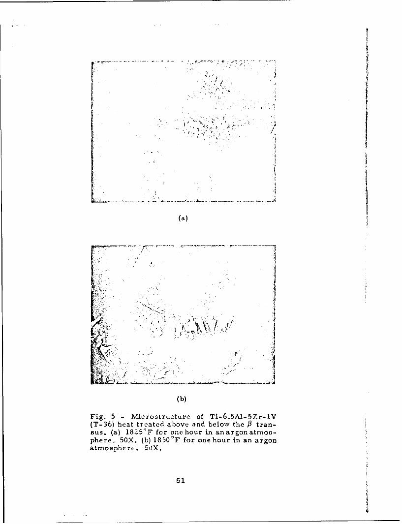
(a)
(b)
Fig. 5 -Microstructure of Ti-6.5A1-5Zr-1V(T-36) heat treated above and below the 0 tran-sus. (a) 182 5'F for one hour in an argon atrnoc-phere. 50X. (b) 1850 OF for one hour in an argonatmosphere. 50X.
61

A
(a)
4 4
¾.; , * .
(a)
62

AA.
v;,4
(b
Fig. 7 Microstruct re of Ti-Ab'r-
(T-55)~~~~~~~ hea trae bveadblw h rsus.~~~~~~ (a 85Ffroehu na ro tns
pher. 50. (b 180cF or oe hur i an rgo
atmoshere.5'OS

(a)
F'ig.8-Mcotut of T -6A-,2nc -7
h at rae bv n eo h 3tass
(a)180"F oronehor n n rgo amophre
644

(a)
77' - -- T7
J: A
(a)
Fig. M-irosructre f T-6Al4ZrZ~I.5Mo.5V(T-6) hat reatd aove nd elo
th4 tanu.()15" ýa fo on hurian ro t opee ,.(I17' o nhor nanago-tmshee 5X
~C
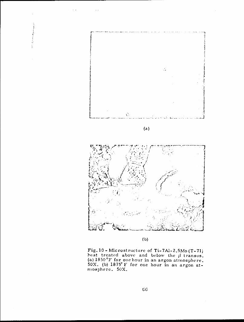
(a)
Fig. 10 -Microstructure of/ Ti-TA-2.5Mo (T-71
I•eat treated above and below the j3 tranSUS.(a) 18 50 'F f or one hour in an a rgon atmos phe re.50X. (b) 1875' F for one hour in an argon at-mosphere. 50X.
66I

10 C
U) (n (AUc
IX000 0 ~ 4
Z 4 WjLd JWU.0A 0 a 0eo
j~~i0 41 44
04 0I ILt.
I II w
0I 0 w
hi Lt I-Z 0x' z 00x rn-
a: 4.e 4 0Dir 0 00
ww 0z 0'
24 iz .14 >w30 +j
0
'-44
0 -0
ISci 0001 X H.LDNJ31S 0131.k 13SAJO %Z'
67

WC)
04
00
Uri
w 0
D > P-4
z -4
0 c
0 10V
w
10
> -
4j -IL
m 0~
0 *N
41
00
0 00 Q00 0
i.?+@(91-j)A983N3 AdUVED
68
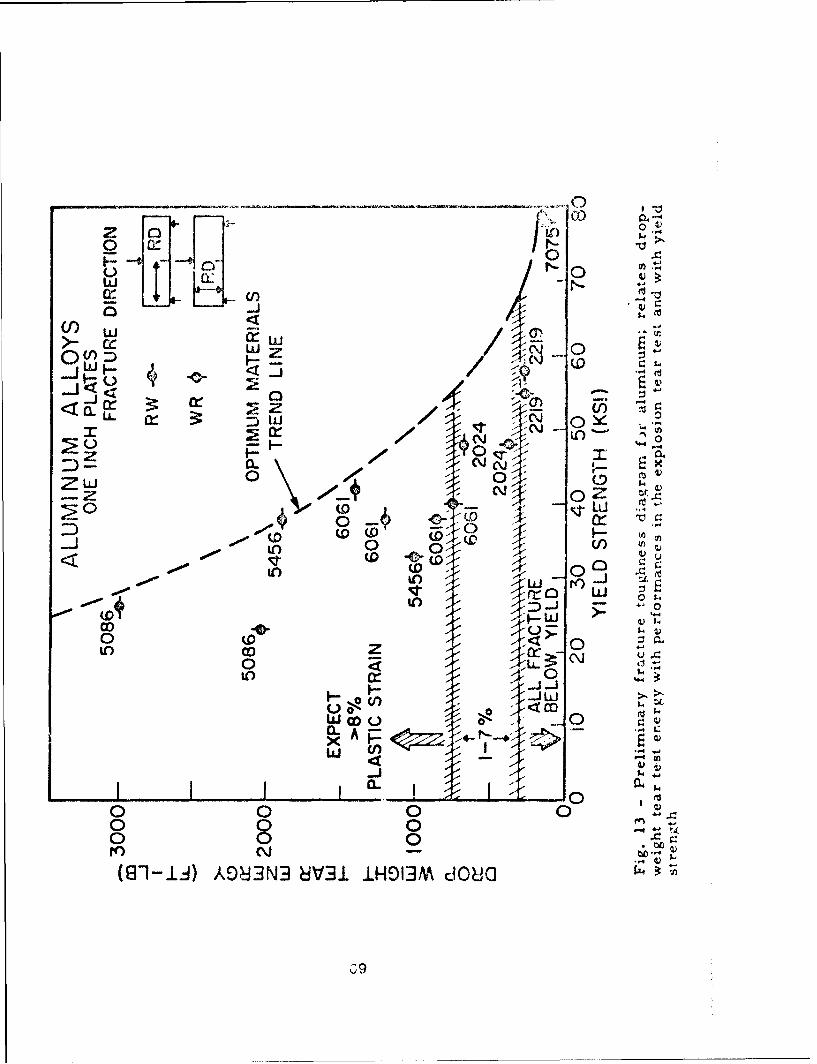
(¾ 0
Z Io) ()pit-._ 0
<-
0j
ozn '-20 /-w 0 ý
0 0
z4ZLI N
-(DZ<2 $5CDC
a~>-~0 0~
IC)j
LO 0
W OD U 0
0 0 0
(8-1-id) AOJ3N3 8V31. iH9IJM dO80

4::4-j
44oth,
0 ~41
~~41
04-
- 4-
70~

041Id.
z 04
C' U
0f a0.
71

C 4(
(0 o0".. C) to00u
C(- 0~ T ) ptoa:L00 0 WW < - u-4,-
C)- C) < O~ 0 C
O-o a q) o U
IY- U)
*00
0>V)33 o)
o aj
5//444' -
00o~~~~1 00~ ~~~~ 00 .
0~~~ 00CX) C tO i() No(S81-.u) A03N cJrJ DHIJ dO*4~
72o

1 % 0o~ o o ý a a W,w I I04x
w 0 0IL on PI) t
Xuuo$09: e 0 00 a 4 4
cr- 00
rr0 ,4
cli
0 u 0
Nl 0 NDc
(81-1:1) A983N3 A -AcrnVHO AoO02
73
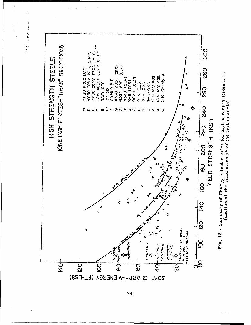
VI co
LO -r- C
UJ CC)iUL~JtL; 4' ~coC. wW> Nl D
C/) 0>>- .0: 0O~L~O rr LJ "1 4
3: Ul < C) C
O- - - > rfol.Z fn O N CO)
Ld ~04 o
I- 0 NU) CL 4
3:0 3- -4~
NN
'a C\iL 4-
4y04
4 u'00
t~OP'~ 0
N4 00 00 0 0
_ N(SS-id V*3N -4dUH d
74

_ _ _ _ __ _ _ _ _ _ _ 0
r0
co
-0)
&LJ 1 e.wQ
oE
1.4J0
~4S4
-C\i0 Lu
9-x >0
0 0
w
0
(D
41~
-------------- _ ou
_ _ _ _ _ _ _ _ _-4-,4
-4
00 00 00 00 000000 o i
r~ N ~ Q O~ 0~ f- (.0 I) A:) ) N
75

Y.S. (KS I)/ .... 150 PLATE
S,•1-0 WELD
-- - \ ,140 PLATE140 WELD
-1 .... 30 PLATE/\ 140 WELD
Fig. 20 - Explosion bulge test plates, after four shots, of 140 ksi steelwith u-ndermatching, matching, and overmatching welds
76

I ID A L!ZE DYE L D F¾OI L E
KNWELD tIETAL10 MILS
(AFFECTED
10 t KSI UNDERMATQ> ON
WELD METAL
10 MATCHHEAT
T AFECEZONE
10 M OILS OVERMATCH
Fi. 1- el roie iarmso blg laeshon n ig 2;dffrece podceMbAoermatching ~ ~ ~ EL orPdrnthn h ed ROIEin-
cae y h aseinswiHEidiATexpcdcontour~~~~ intAasneo h ed
77E

V
/"
Fig. 22 - Charpy V-notch specimens of Ni-2Bealloy in annealed condition tested at -320aF(258+ ft-lb)
78

00
3; 4J
0
0 0 0
04
U. 0X 0
0 0 04UU 0
o ~0 0
x2
0 0
0
0w l
(0-1-lI) A98JJN3 A Ad8VHO
79

44 .
N "All
~ \. .- ~ -A
7I
E; 0

- p
7
.0r,' I"
*J
- ' •' - - : . ...,
"lilt
Fig. 25 .Electron fr'actographi of Ni-Z~e, in full hard condi-tion. Note small dimple size and lack of evidonc,- of grossplastic deformation. 3000X. (Reduced approxiimately 20",in printing)
- l ,.

I~A
Fig. 26 -NRL 240,000 ft-lb capacity drop-weight te~ facility

U)/
- ~ 0 w
LL.g..CO 00
0-o z. x0 CO~ w.
0 0 .0-4a LA)
U..
00
C 4 jN
t.L
0I .0if II l c DI
% NI8S3VNm3DUA
834

:• ~20,o0o00ff[
PLATE CEND FATIGUE- 'cc-,Ic-TITANHU74 ALLOYS
oooFULL-r•.:V•RnsE .• ...... fl0,•,•, CYCLU.:
16,000-PROPOR~TIONAL ~O0TCA
LIMIT 0 , LIMIT
TOTAL STRAIN RANGE/UNALLOYED /TOTAL
14,000 ,- TITANIUM /STRAIN RANGETi-7AI -2Cb-ITh
z
w 12,000
z
- 10,000' - /0/
w/
'~8000 /z/
I-000 ./ PLASTIC STRAIN RANGE -
PROPORTIONAL / UNALLOYED TITANIUM
LIMIT //4000 PLASTIC STRAIN RANGE
4000 / Ti--6AI -4V
PLASTIC STRAIN RANGE
2000- Ti -7AI -2Cb -ITc,-
0 0.10 0.20 0.30 0.40 0.50 0.60 0.70
DEFLECTION (INCHES)
Fig. 28 - Strain range-deflection characteristics of unalloyed titanium,Ti-6AI-4V and Ti-7A1-2Cb-ITa alloy plate bend fatigue specimens infull-reverse loading cycle
04

TITAUWJ / KLOY, - . .. , CYCLE
AIR E•'V " .:;'r
b JoU 100 - 0
W
z
W
,a
zt
10-
SYMBOL CODE MATERIAL0 T5 TI-6AI 4V
D T27 TI -6A! -4V
I TA2 TI - 7AI - 2Cb- ITo
0 T16 UNALLOYED TITANIUM,
1.0 - I I I I I I , I I I I II
1000 10,000 100,000TOTAL STRAIN RANGE (MICRO-INCHES/INCH)
Fig. 29 - Log-log plot of fatigue crack growth rate vs. appliedtotal strain range data in full-reverse bending for unalloyedtitanium, Ti-6A1-4V and Ti-7A1-2Cb-lTa alloys in an airenvironment.
85

1000 ----- ,-~r~PLATE VDrATICU i T. ~TFULL-rýv!n; LTJ%:;:EZVI4,G CYCL
A1I,
100 I
U - Iz
7(0 C~o
7/ OEI RPRI0LLMTSRI AG
10.0
RATI OFTOTA STAIN ANG TOPROPORTIONAL LIMIT STRAIN RANGEf
Fig. 30 - Relationship between fatigue crack growth rate vs.ratio of total strain range to proportional limit strain rangefor three titanium alloys. The 2024 aluminum and H-Y-80steel relationships are shown for comparison.
0,6

1000 1
-T1TA!NU?^_ t-.LI-0 2 0-FULL-,1.ZVLYI: ; , VD CYCSALT VX% 2 m(:.';2
gtJ PLOT OF-SIM IL AR TITANI~UM1 DATA
IN AIR0
AO
10 p
SYMDOL CGiOE MATERFJALP 0 T5 TI-GAl -4V
0 T27 Ti-6AI -4V
A TA2 TI-7AI -2Cb -ITa
1.0 ~TOTAL srRAIN RANGE (M!CrO- I NCVES /INCH) . p~~o
Fig. 31 - Log-log plot of fatigue c rack growýth rate vs. appliedtotal strain range dat-a in full- reverce bend~Ing for Ti- 6A-1-4V
and Ti-7A1-2Cb-ITa alloys in a 3.57osalt water environment
87

x 0
00
x 4
10
o A 4-'
C,)
-J 0
X >:0 z x0$1
-J - KOu mo 0 00 -
iA LL) z 0V 0-o zX c 0 9-
C) L) n x0U.ILJ 00 LL)a.
IL0 LLj x in 0 2 0 0 P
C~C) 0 x x u
cr. _ < _
c2 !aC v L I:
D Xe
0 o.LOda NI(74.A*H-AG~QOJ1
U.O61SVAU~~H~N rC 3 9 1'+
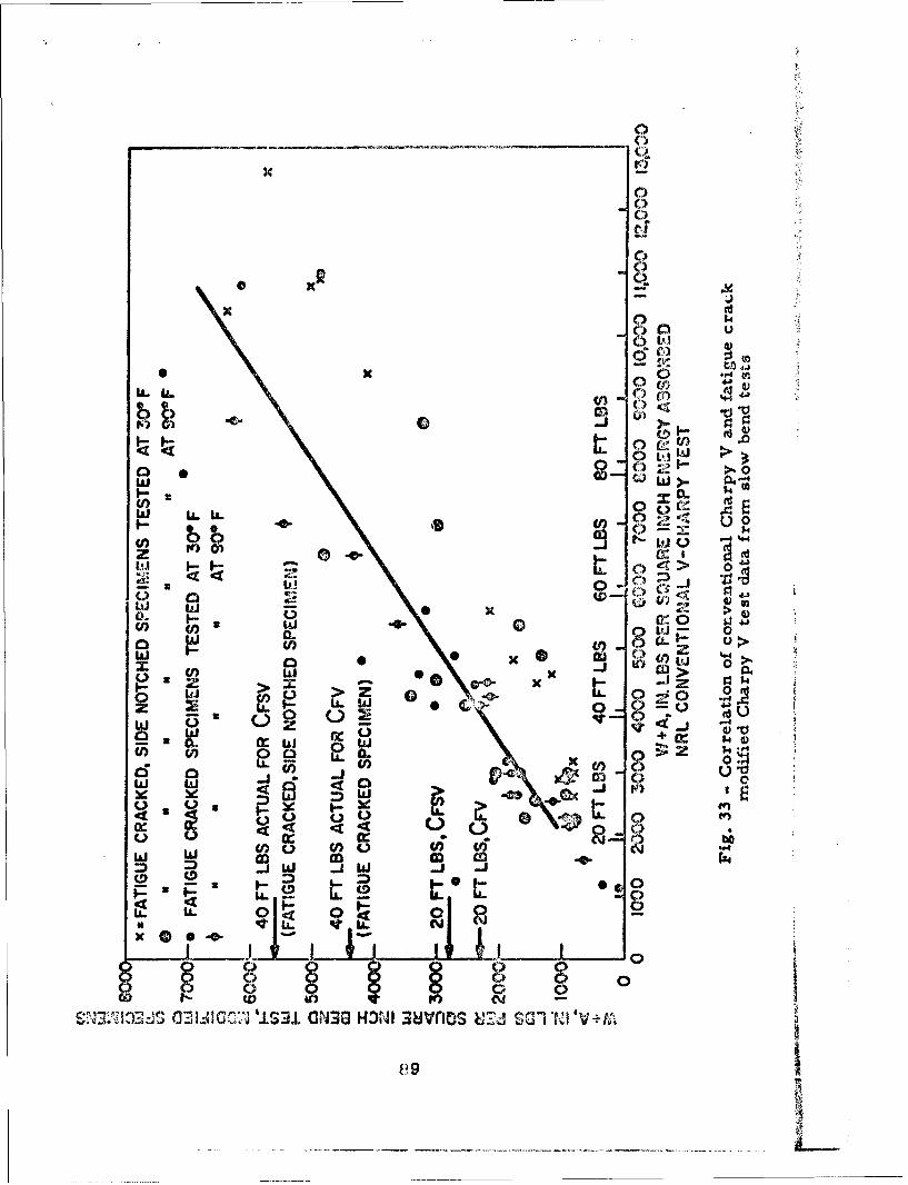
xC
xC
x
xx0.
C)L'
C:
M kZ44 t
Iii biAI 0 >4. .4 4
() 0
(n Id * _j ca> :
2:C CL 0LJ 0 31
Cl) _jC~ 1
0 0 X WQ~~
LLC. X &) C
L) U.
D ~ 01L17
SOG3UGr.2J 'IS 3.. aN30 HOWI 3uJvnt~s u.h S(Vi s d G '1v -f
v 9

~CI
no Ji:) <:LUJ WLLLL Cf
(n . 0 Co
LJ0 0 C Q>-, cJ _j _ j-
0 40 %t 4-4 0< C) C~j y -0
00
z zZ~ *: wW in>
4 0
* 84
0 *0 (U
* 01 0
0 *4 04t
01 1 1 1 1 1 0
r~) N 0 0) m) N- w LO)'J r N
(8"1 1 J) A08dIN3 cJVC
00

Security CI• CCc 'XAW
I OQtrINATI04 G ACTIVI'Y (CoIpý,Qte &uYhot) Aj I 3R; SbjI TC'ý LA'TIF'ýAION
U.S. Naval Research Laboratory UNCLASSIFIEDWashington, D.C. - 20390 7b GACUP
3 APPORT TITLE
METALLURGICAL CHARACTEIUSTICS OF HIGH STRENGTHSTRUCTURAL MATERIALS (Sixth Quarterly Report)
4 DESCAIPTIVE NOTES (Ty" of report end tnclusv. date.)
In interim report on one phase of the problem.5 AUTHOn($) (Lonme . It•.! nam. intei&) Crooker, T.W.
Pellini, W.S. Howe, D.G. Lloyd, K.B. Mrey, T.W.Goode, R.J. Judy, R.W., Jr. Lange, E.A. Chaei, E.J:' ~Chapin, E.J.Huber, R.W. Puzak, P.P. DeFelice, E.A. ir ds,
G. REPORT DATE 7e TO .L NO OF PAGES 7b NO O0C IGfS
December 1964 95 17$. CONTRACT OR GRANT NO 63M01-05, M01-18'"s ORIINATOf'S *TPORT NUMER,(S)
and M03-01, 63R05-24A and -24Bb. PROJiCT NO SR 007-01-02-0704; 1 NRL Report 6258SR 007-01-01-0856, -0854, and-0850;
ORR 007-01-46-5405 and- 5420; is '.,o"oWW 041
10 AVA IL ABILITY/LIMITA ION NOTICES Unlimited availability. Available at Cl;aringhouse
,or Federal Scientific and Technical Information (CFSTI), Sills Building, 5285Port Royal Road, Springfield, Virginia 22151
11 SUPPL EMENTARY NOTES Ii SPONSOIINO MILITARY ACTIVITY
Department of the Navy (Bureau of shipsand Office of Naval Research)
I, ABSIRACT A progress report covering research studies in high strength hullstructural materials, conducted in the period September 1964 to December 1964,is presented. Included in the report are fracture toughness studies on: (1) titani-urn alloys as related to processing variables (including diffusion-bonding), thick-ness, and heat-treatment, (2) aluminum, (3) high strength steels relating pri-marily to the 5Ni-Cr-Mo-V steels, and (4) a nickel-beryllium alloy. Low cyclefatigue crack propagation studies on several titanium alloys are presented as wellas a general review of the status of the titaniu.n casting industry. The U.S. NavalResearch Laboratory's new 240,000 ft-lb laboratory drop-weight bulge testingfacility is described and a preliminary correlation of the results obtained with it iand the explosion bulge test are presented. 'he results of a study using fatiguecracked and side notched Charpy specimens in impact and slow berd testing on awide variety of steels is given. The results are compared to those :btained in thestandard Charpy test using the same materials. A background statement describ-ing the "philosophy" of testing and evaluation of high strength stiuc;.,ral materialswhich is the basis of the program is included in txis report.
DD IA°"" 1473 91Sec'urity Cla,•qificatbon

L LI NK A LIN K 0 U11lIEngineeri7 r~rcids Drop- /el.ght Tear . ~•~I1 1Titaniuim A1,11yC Test
FAluminum Abloyrt Proce 5,.-ngHigh st rerýIllt /c Va riablCFracture Tc:i-ýý,n: r;r, Heat TrealincntNickel-Bolryllium Alloy Strain Ra~nseDrop-Weight roulyc TeiA EffectsLow Cycle FatigueCorrosion F~itigueTitanium Cafntingr,Fat~igue Cracked CharpySide Notched CharpyMechanical PropertiesDiffusion~ '3onding
Explosion Tear Test
INSTRUCTIONS
1. ORIGINATIN.G ACTIlVITY: Enter th~e namne and zddets imposed by security classific in, using standard etatemner~sof the contractor, *ubcon'r-!r.!tr grantee. Dec'3rtmr'r't of De- such ais:
le nse activity or other orrgzniziition (corporate auihor) inikn I.) "Quralified re iester% me)~ obtain copies of this'he rport. report from DDC.."2s. REPORT SECUEMTY CLASSIFICATION: Enter the o'~et- (2) "Foreign announcerne-t and dissemination of thisall security clAssificat.,on of the reror'. Indicate whetherreotb Visntahrzd."Restricted D-ita" is included. Marking is to be in accord-rpotb Cisn atoze.ance with appropriate security regulations. (3) "U. S. Government agencies may obtain copies of
this Meort directly from DDtC. Other qualified DDC2b. GROUP: Automahtic downgyading is specified in DoD Di- users shall request throughrective S200. 10 and Arned Forces Industrial Manual. Enterthe group number Also. when spolicable. show that .,ptional--mnarkings have, been uved fcr Go4up 3 and Group 4 as author- (4) "UL S. n'iiitary agen~ies may ohtain ropient of thistied report diectly from Dr)c Othc-r qujatifiedý usora3. REPORT TITLE: Ermer the conplete report title in all shiell requiest throughcapital letters. Title% in all ci:ses sh-,uld he onclasuiifrrrt.If a meaningful title cannot be uclected without clnsrifice-tion. show title closf.,ficgtion in all capitals in parenthesis (5) "All dintribution of this report is controlled. Quial-immediaitely following the title, ified DDC users shall request through
4. DESCRIPTIVE NOTE&S If appropriate, enter the type of ______________.0_______
report. e g.,* interim, pro$,renss summary, annual, or final. If the report has been furnished to the Office of TechnicalGive the inclusive dates when a specific reporting period is Services, Department of Commerce. for sate to the public, indi-covered. cate this fact and enter the price, if known.S. AUT1IOR(S)ý Enter the namne(s) of author(s) as shown on 11, SUPPLEFIlrNTARY NOTES: ?fee for additional explana-or in the report. Entri last 'awre, first name, middle initial, tory notes.If military, show rank ain' bruanch of se-vice. The name ofthe principal ,aithor is an stbsolute minimum requirement. 12. SPONIX)RlNG MILITARY ACTIVITY: Enter the name of
the depart mental project office or laboratory sponnoring (pay.6. RLPORT 1)ATyI. Enter the date of the report an day. ind for) the research and development. Include address.moidtt, year, or rionth, year. If rn~or than one 'aste appearson the report. use date of publication. 13 ABSTRACT: Enter an abstract giving a brief and factual
summary of the document indicative of the report, even though7s. TOTAL, NUMBlER OF PAGES: *The total page count it may also appear elsewhere in the body of the technical re-ithould follow normal pagignation procedures, i.e., enter the port. If additional space is required, a continuation sheet shaltnumbher of pages containing infvrrration. be attached.7b. NUW!iER OF REFERENCES*. Enter the total number of It is highly desirable that the abstract of classified reportsreferences cited in the report. be unclassz~fied. Each paratoraph of the abstract shall end withBe. CONTRACT OR GRANT NUMBER: If appropriate, enter an indication of the military security classification of the in-the applicable numbher of the contract or grant tinder which formatiori in the paragraph, represented as (rs). (v). (c). or (u)the re-port was written. There is no limitittions on the length of the abstract Hoav.8b, &-,. & ltd. PROJECT NUMBFER: Enter the appropriate ever the suggested length is from 150 0~ 225 wordsmilitary departmient identification. such as project number, 1 E OD:Kywrsaetcnclymaigu emsubproject number. system numbers, tasty number, etc. 1 E OD:Kywrsaetcnclymaigu em
or short phrfases that characterize a report and may be used as9a. OPIGINATOR'S REPORT NUMBER(S): Enter the offi- index entries for cslaloginf. the report. Key wvords mist becial report number by whitch the document will be identified select,,d so that no security classification is required Identi-and controlled by the originating activity. This number mtust fires. %so'h as equqipmnti model dei'~jcnation, trade name, militarybe uniqlue to this report. project code name. geographic toc ation. may be used as key
9b OTHEIR W.PORT NUMrtER-S): If the report has been word's but will be followred by an indication of tecl-nical con-ossigni-r any other report rumbers (eirher by thie originarui tet Thei ossignrcirnt of links, roles and weights is optional.or by the spo'nsor). also enter this numbe-r(s).
10. AVAIL.ABILITY/Limi rATION NOTICE& Enter ary lim-itation in further dissemination of the report, other thain those
92Security Claissificationi

z. :I-
:L j %ý
a S.U --3 CL
z Z
0. o *
.7 . .4 .. . ..~~~.0~~ >0~ . 4 U .t
A0 A
c- ,.. . -Q
In >,: no LA
U .7 3.. U.U.2
v Y. t 0 V ;
0~,30~3,, ~Wt ~.~%~'O5.,

Ut x
4,
5 o ~ ~ LA
u~
rn -
3 z- >f
A..
trt
~ ~ ~ at7j
-~ ..~ at
j cL-
CL tt X. n