Metallized Nanotube Polymer Composite (MNPC) - … · Metallized Nanotube Polymer Composite (MNPC)...
28
Metallized Nanotube Polymer Composite (MNPC) Cheol Park , Jae-Woo Kim, Godfrey Sauti, Jin Ho Kang, Peter T. Lillehei*, Sharon E. Lowther*, Joycelyn S. Harrison*, Negin Nazem**, Larry Taylor*** National Institute of Aerospace, Hampton VA *Advanced Materials & Processing Branch, NASA Langley Research Center, Hampton, VA **Department of Chemistry, Virginia Tech, Blacksburg, VA Materials Research Society, Boston, MA November 29, 2007 https://ntrs.nasa.gov/search.jsp?R=20080000871 2018-09-07T13:53:43+00:00Z
Transcript of Metallized Nanotube Polymer Composite (MNPC) - … · Metallized Nanotube Polymer Composite (MNPC)...
Metallized Nanotube Polymer Composite(MNPC)
Cheol Park, Jae-Woo Kim, Godfrey Sauti, Jin Ho Kang, Peter T. Lillehei*, Sharon E.Lowther*, Joycelyn S. Harrison*, Negin Nazem**, Larry Taylor***
National Institute of Aerospace, Hampton VA*Advanced Materials & Processing Branch, NASA Langley Research Center,
Hampton, VA**Department of Chemistry, Virginia Tech, Blacksburg, VA
Materials Research Society, Boston, MANovember 29, 2007
https://ntrs.nasa.gov/search.jsp?R=20080000871 2018-09-07T13:53:43+00:00Z
Outline
• Motivation• Approach• SWCNT-Polymer Composites• MNPC• Morphology• Physical properties• Summary
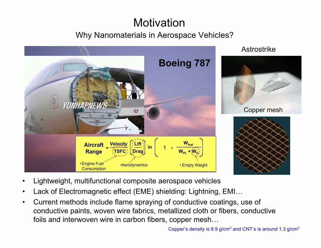
Why Nanomaterials in Aerospace Vehicles?
• Lightweight, multifunctional composite aerospace vehicles• Lack of Electromagnetic effect (EME) shielding: Lightning, EMI…• Current methods include flame spraying of conductive coatings, use of
conductive paints, woven wire fabrics, metallized cloth or fibers, conductivefoils and interwoven wire in carbon fibers, copper mesh…
Motivation
Boeing 787
Velocity
TSFC
Lift
Dragln
Wfuel
WPL + WO
=
•Aerodynamics • Empty Weight • Engine Fuel
Consumption
Aircraft
Range1 +
Velocity
TSFC
Lift
Dragln
Wfuel
WPL + WO
=
•Aerodynamics • Empty Weight • Engine Fuel
Consumption
Aircraft
Range1 +
Astrostrike
Copper mesh
Copper’s density is 8.9 g/cm3 and CNT’s is around 1.3 g/cm3
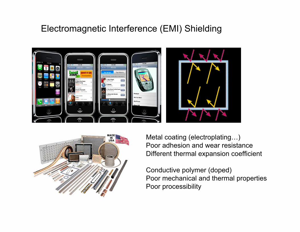
Electromagnetic Interference (EMI) Shielding
Metal coating (electroplating…)Poor adhesion and wear resistanceDifferent thermal expansion coefficient
Conductive polymer (doped)Poor mechanical and thermal propertiesPoor processibility
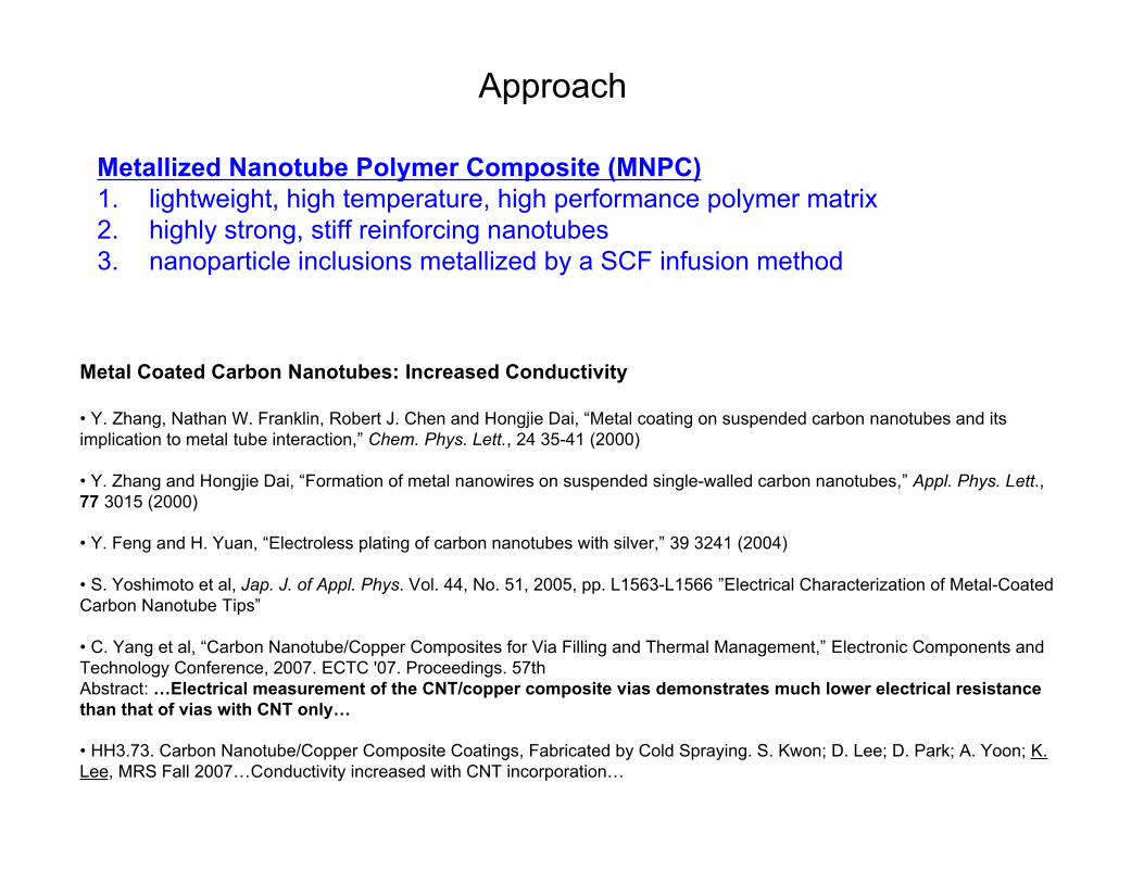
Approach
Metallized Nanotube Polymer Composite (MNPC)1. lightweight, high temperature, high performance polymer matrix2. highly strong, stiff reinforcing nanotubes3. nanoparticle inclusions metallized by a SCF infusion method
Metal Coated Carbon Nanotubes: Increased Conductivity
• Y. Zhang, Nathan W. Franklin, Robert J. Chen and Hongjie Dai, “Metal coating on suspended carbon nanotubes and itsimplication to metal tube interaction,” Chem. Phys. Lett., 24 35-41 (2000)
• Y. Zhang and Hongjie Dai, “Formation of metal nanowires on suspended single-walled carbon nanotubes,” Appl. Phys. Lett.,77 3015 (2000)
• Y. Feng and H. Yuan, “Electroless plating of carbon nanotubes with silver,” 39 3241 (2004)
• S. Yoshimoto et al, Jap. J. of Appl. Phys. Vol. 44, No. 51, 2005, pp. L1563-L1566 ”Electrical Characterization of Metal-CoatedCarbon Nanotube Tips”
• C. Yang et al, “Carbon Nanotube/Copper Composites for Via Filling and Thermal Management,” Electronic Components andTechnology Conference, 2007. ECTC '07. Proceedings. 57thAbstract: …Electrical measurement of the CNT/copper composite vias demonstrates much lower electrical resistancethan that of vias with CNT only…
• HH3.73. Carbon Nanotube/Copper Composite Coatings, Fabricated by Cold Spraying. S. Kwon; D. Lee; D. Park; A. Yoon; K.Lee, MRS Fall 2007…Conductivity increased with CNT incorporation…
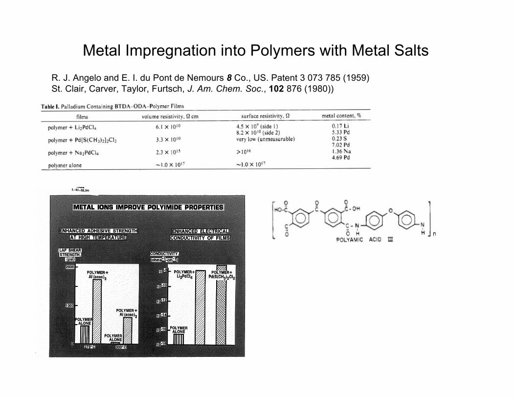
R. J. Angelo and E. I. du Pont de Nemours 8 Co., US. Patent 3 073 785 (1959)St. Clair, Carver, Taylor, Furtsch, J. Am. Chem. Soc., 102 876 (1980))
Metal Impregnation into Polymers with Metal Salts
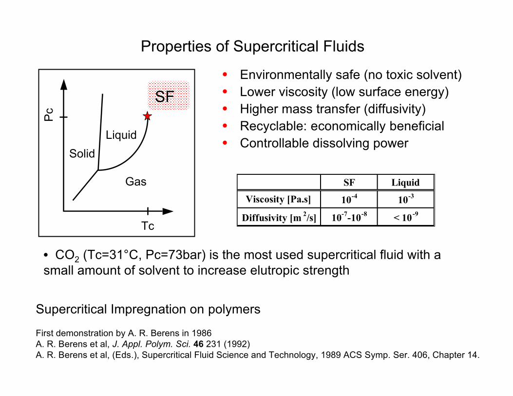
• Environmentally safe (no toxic solvent)• Lower viscosity (low surface energy)• Higher mass transfer (diffusivity)• Recyclable: economically beneficial• Controllable dissolving power
SF Liquid
Viscosity [Pa.s] 10-4
10-3
Diffusivity [m2/s] 10
-7-10
-8< 10
-9
• CO2 (Tc=31°C, Pc=73bar) is the most used supercritical fluid with asmall amount of solvent to increase elutropic strength
Properties of Supercritical Fluids
Tc
Pc
Liquid
Gas
Solid
SF
Supercritical Impregnation on polymers
First demonstration by A. R. Berens in 1986A. R. Berens et al, J. Appl. Polym. Sci. 46 231 (1992)A. R. Berens et al, (Eds.), Supercritical Fluid Science and Technology, 1989 ACS Symp. Ser. 406, Chapter 14.
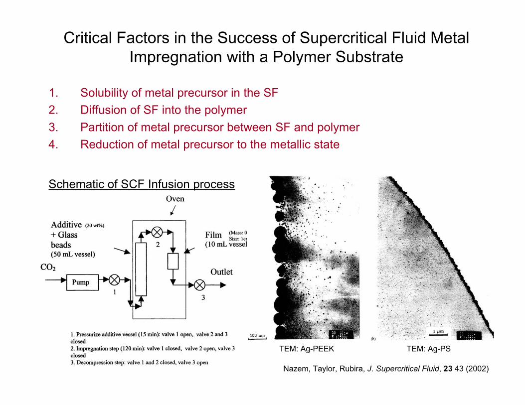
Critical Factors in the Success of Supercritical Fluid MetalImpregnation with a Polymer Substrate
1. Solubility of metal precursor in the SF2. Diffusion of SF into the polymer3. Partition of metal precursor between SF and polymer4. Reduction of metal precursor to the metallic state
Schematic of SCF Infusion process
TEM: Ag-PEEK TEM: Ag-PS
Nazem, Taylor, Rubira, J. Supercritical Fluid, 23 43 (2002)
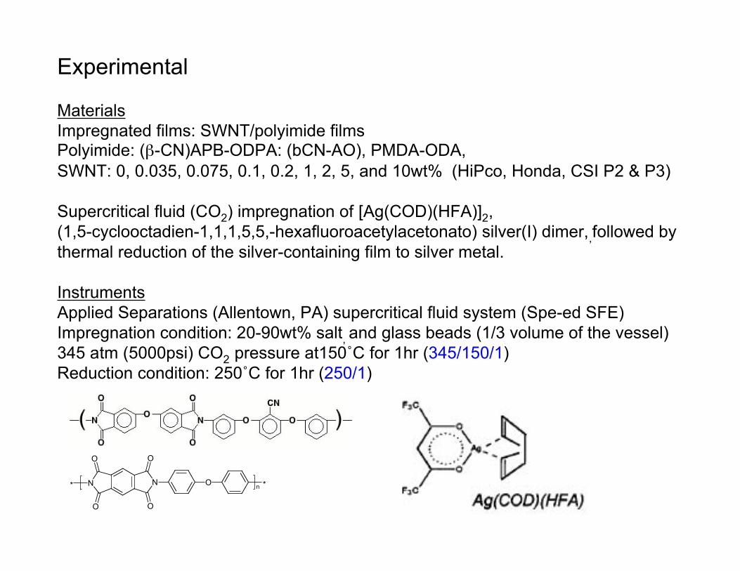
Experimental
MaterialsImpregnated films: SWNT/polyimide filmsPolyimide: (β-CN)APB-ODPA: (bCN-AO), PMDA-ODA,SWNT: 0, 0.035, 0.075, 0.1, 0.2, 1, 2, 5, and 10wt% (HiPco, Honda, CSI P2 & P3)
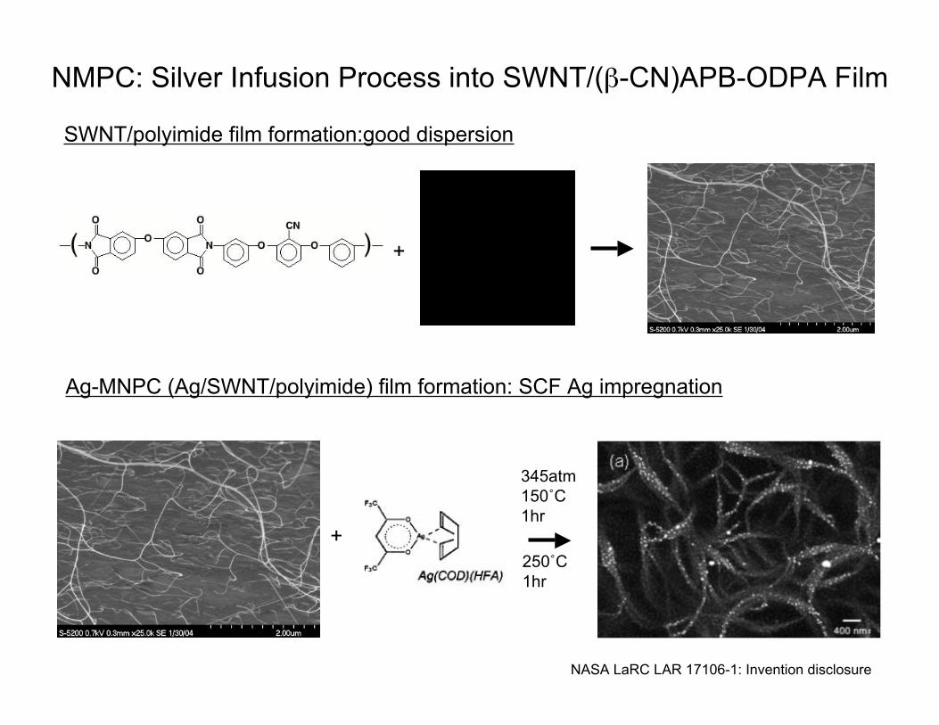
Supercritical fluid (CO2) impregnation of [Ag(COD)(HFA)]2,(1,5-cyclooctadien-1,1,1,5,5,-hexafluoroacetylacetonato) silver(I) dimer,,followed bythermal reduction of the silver-containing film to silver metal.
InstrumentsApplied Separations (Allentown, PA) supercritical fluid system (Spe-ed SFE)Impregnation condition: 20-90wt% salt, and glass beads (1/3 volume of the vessel)345 atm (5000psi) CO2 pressure at150˚C for 1hr (345/150/1)Reduction condition: 250˚C for 1hr (250/1)
N N
O
O
O
O
O* *n
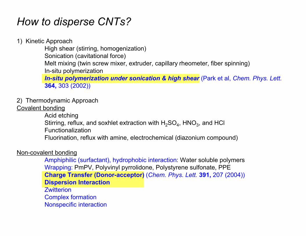
How to disperse CNTs?1) Kinetic Approach
High shear (stirring, homogenization)Sonication (cavitational force)Melt mixing (twin screw mixer, extruder, capillary rheometer, fiber spinning)In-situ polymerizationIn-situ polymerization under sonication & high shear (Park et al, Chem. Phys. Lett.364, 303 (2002))
2) Thermodynamic ApproachCovalent bonding
Acid etchingStirring, reflux, and soxhlet extraction with H2SO4, HNO3, and HClFunctionalizationFluorination, reflux with amine, electrochemical (diazonium compound)
Non-covalent bondingAmphiphilic (surfactant), hydrophobic interaction: Water soluble polymersWrapping: PmPV, Polyvinyl pyrrolidone, Polystyrene sulfonate, PPECharge Transfer (Donor-acceptor) (Chem. Phys. Lett. 391, 207 (2004))Dispersion InteractionZwitterionComplex formationNonspecific interaction
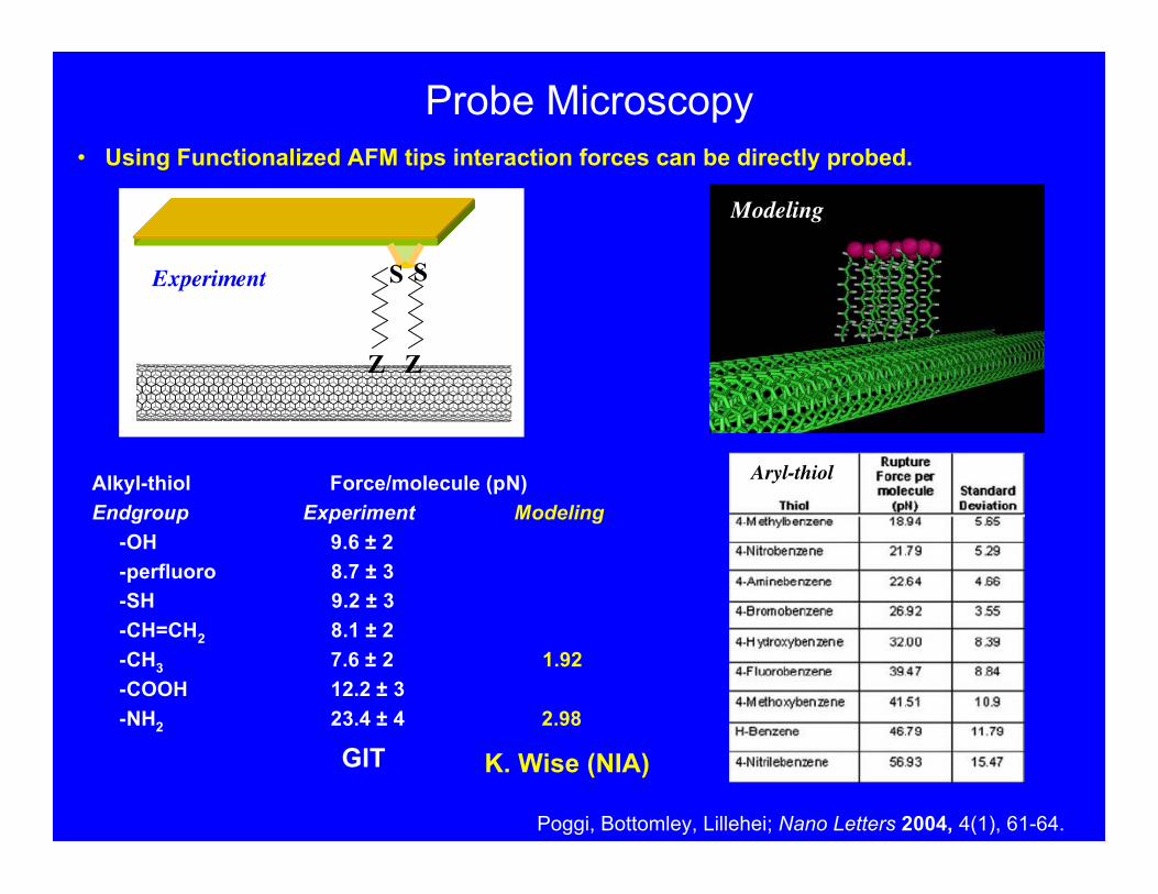
Alkyl-thiol Force/molecule (pN)Endgroup Experiment Modeling
-OH 9.6 ± 2-perfluoro 8.7 ± 3-SH 9.2 ± 3-CH=CH2 8.1 ± 2-CH3 7.6 ± 2 1.92-COOH 12.2 ± 3-NH2 23.4 ± 4 2.98
Probe Microscopy
K. Wise (NIA)GIT
Poggi, Bottomley, Lillehei; Nano Letters 2004, 4(1), 61-64.
Z Z
S SExperiment
Modeling
Aryl-thiol
• Using Functionalized AFM tips interaction forces can be directly probed.
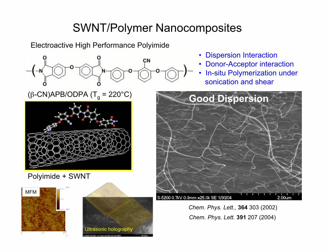
SWNT/Polymer Nanocomposites
(β-CN)APB/ODPA (Tg = 220°C)
Polyimide + SWNT
Electroactive High Performance Polyimide
Chem. Phys. Lett., 364 303 (2002)
Good Dispersion
• Dispersion Interaction• Donor-Acceptor interaction• In-situ Polymerization under sonication and shear
Chem. Phys. Lett. 391 207 (2004)
MFM
Ultrasonic holography
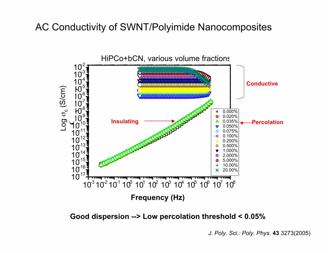
AC Conductivity of SWNT/Polyimide Nanocomposites
10-3
10-2
10-1
100
101
102
103
104
105
106
107
108
10-17
10-16
10-15
10-14
10-13
10-12
10-11
10-10
10-9
10-8
10-7
10-6
10-5
10-4
10-3
10-2
HiPCo+bCN, various volume fractions
!' ("
cm
)-1
Frequency(Hz)
0.000% HiPCo+bCN (PC455-32-10) 0.020% HiPCo+bCN (PC427-46-13) 0.035% HiPCo+bCN (PC427-71-09) 0.050% HiPCo+bCN (PC455-24-30) 0.075% HiPCo+bCN (PC455-44-09) 0.100% HiPCo+bCN (PC379-96) 0.200% HiPCo+bCN (PC455-34-11) 0.500% HiPCo+bCN (PC427-49-13) 1.000% HiPCo+bCN (PC427-48-13) 2.000% HiPCo+bCN (PC427-34-11) 5.000% HiPCo+bCN (PC427-31-10) 10.00% HiPCo+bCN (PC455-37-19) 20.00% HiPCo+bCN (PC455-51-18)
PercolationInsulating
Conductive
Log σ
c (S
/cm
)
Frequency (Hz)
J. Poly. Sci.: Poly. Phys. 43 3273(2005)
Good dispersion --> Low percolation threshold < 0.05%
+
+
345atm150˚C1hr
250˚C1hr
NMPC: Silver Infusion Process into SWNT/(β-CN)APB-ODPA Film
SWNT/polyimide film formation:good dispersion
Ag-MNPC (Ag/SWNT/polyimide) film formation: SCF Ag impregnation
NASA LaRC LAR 17106-1: Invention disclosure
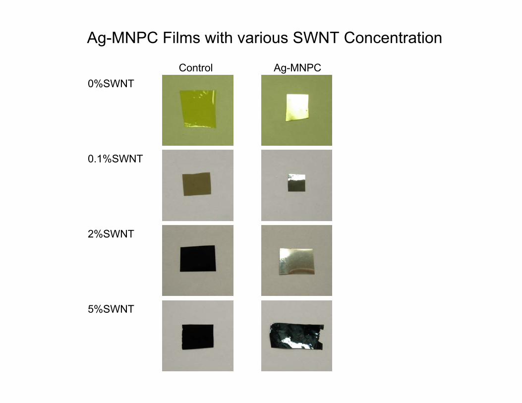
0.1%SWNT
0%SWNT
2%SWNT
5%SWNT
Ag-MNPC Films with various SWNT Concentration
Control Ag-MNPC
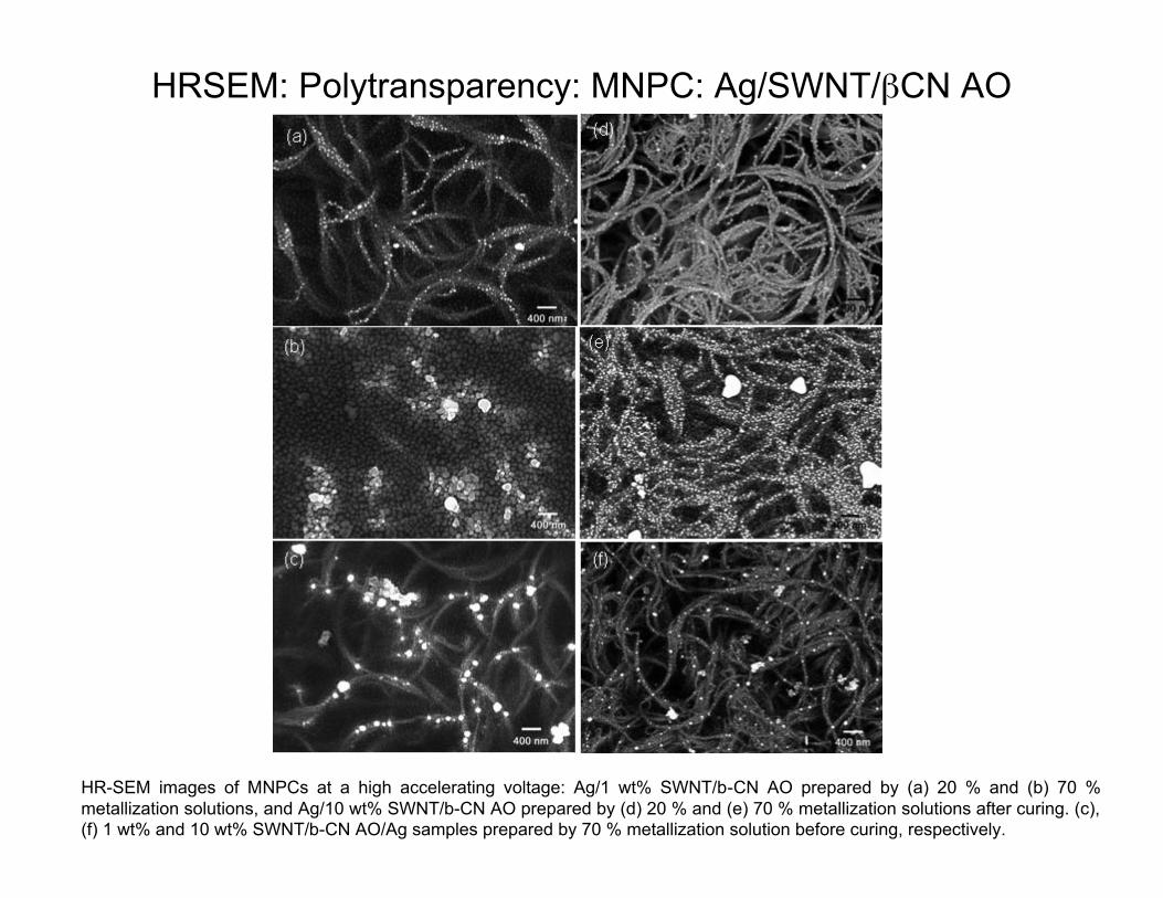
HR-SEM images of MNPCs at a high accelerating voltage: Ag/1 wt% SWNT/b-CN AO prepared by (a) 20 % and (b) 70 %metallization solutions, and Ag/10 wt% SWNT/b-CN AO prepared by (d) 20 % and (e) 70 % metallization solutions after curing. (c),(f) 1 wt% and 10 wt% SWNT/b-CN AO/Ag samples prepared by 70 % metallization solution before curing, respectively.
HRSEM: Polytransparency: MNPC: Ag/SWNT/βCN AO
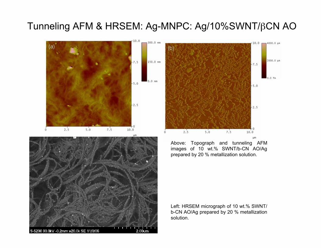
Above: Topograph and tunneling AFMimages of 10 wt.% SWNT/b-CN AO/Agprepared by 20 % metallization solution.
Tunneling AFM & HRSEM: Ag-MNPC: Ag/10%SWNT/βCN AO
Left: HRSEM micrograph of 10 wt.% SWNT/b-CN AO/Ag prepared by 20 % metallizationsolution.
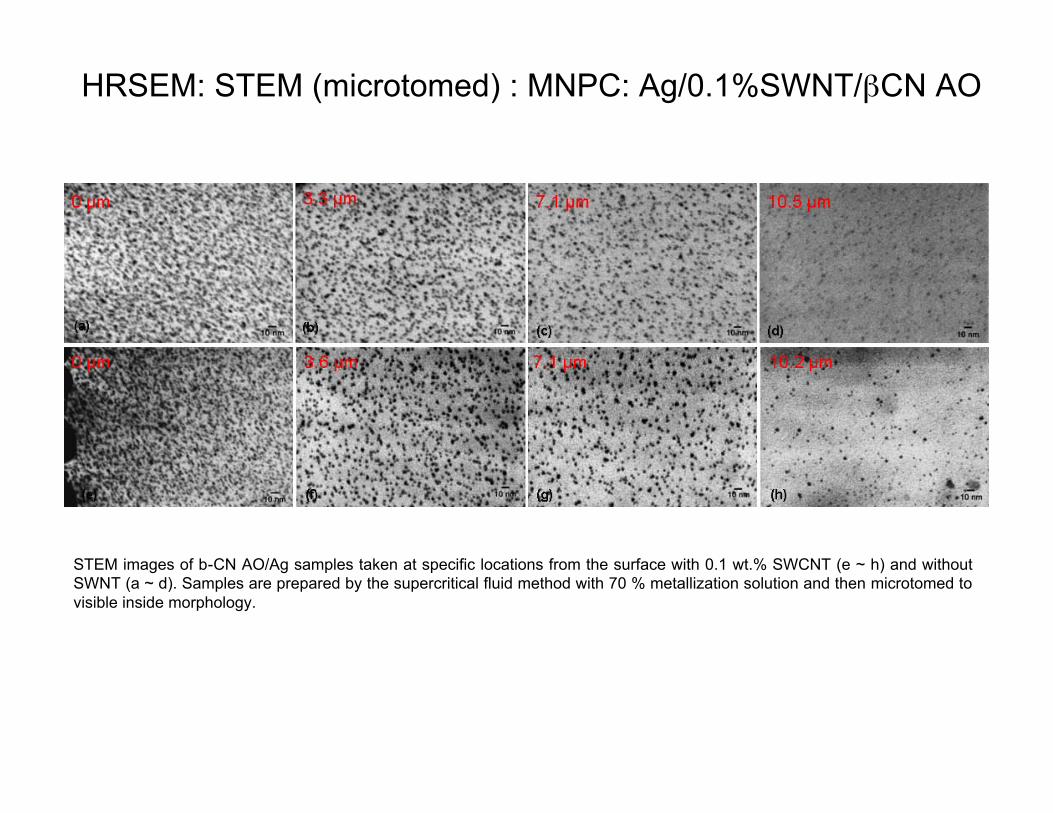
HRSEM: STEM (microtomed) : MNPC: Ag/0.1%SWNT/βCN AO
STEM images of b-CN AO/Ag samples taken at specific locations from the surface with 0.1 wt.% SWCNT (e ~ h) and withoutSWNT (a ~ d). Samples are prepared by the supercritical fluid method with 70 % metallization solution and then microtomed tovisible inside morphology.
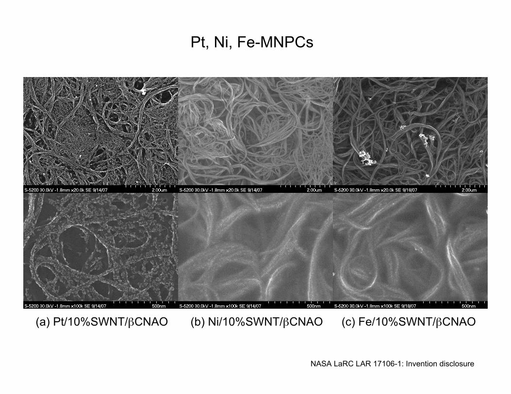
(a) Pt/10%SWNT/βCNAO (b) Ni/10%SWNT/βCNAO (c) Fe/10%SWNT/βCNAO
Pt, Ni, Fe-MNPCs
NASA LaRC LAR 17106-1: Invention disclosure
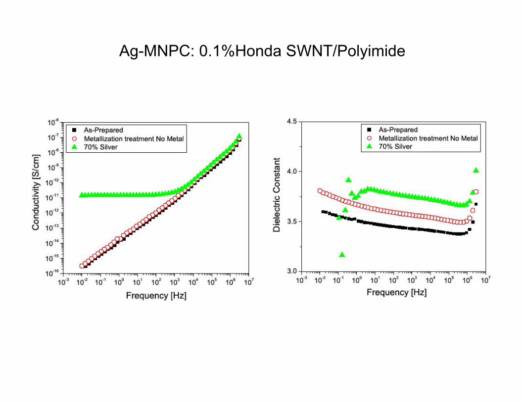
Ag-MNPC: 0.1%Honda SWNT/Polyimide
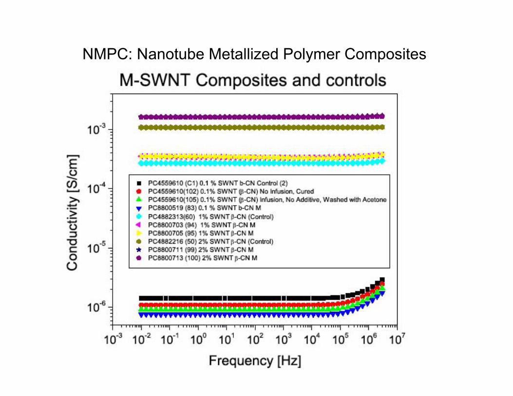
NMPC: Nanotube Metallized Polymer Composites
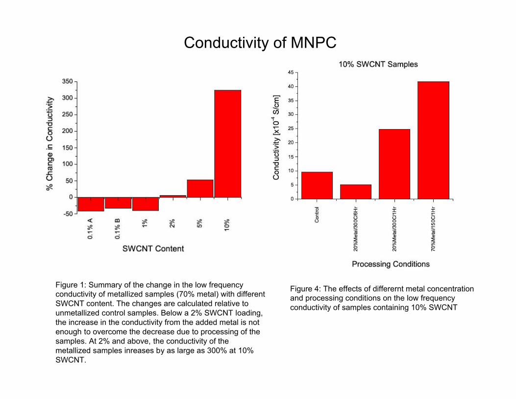
Figure 1: Summary of the change in the low frequencyconductivity of metallized samples (70% metal) with differentSWCNT content. The changes are calculated relative tounmetallized control samples. Below a 2% SWCNT loading,the increase in the conductivity from the added metal is notenough to overcome the decrease due to processing of thesamples. At 2% and above, the conductivity of themetallized samples inreases by as large as 300% at 10%SWCNT.
Figure 4: The effects of differernt metal concentrationand processing conditions on the low frequencyconductivity of samples containing 10% SWCNT
Conductivity of MNPC
0 50 100 150 200 250
-0.005
0.000
0.005
0.010
0.015
0.020
0.025
-0.1
0.0
0.1
0.2
0.3
0.4
0.5
0.6
Str
ain
(%
)
!R/R0
!R
/R0
Time (sec)
Strain (%)
0 50 100 150 200 250
0.000
0.001
0.002
0.003
0.004
0.0
0.1
0.2
0.3
0.4
0.5
Str
ain
(%
)
!R
/R0
Time (sec)
!R/R0 Strain (%)
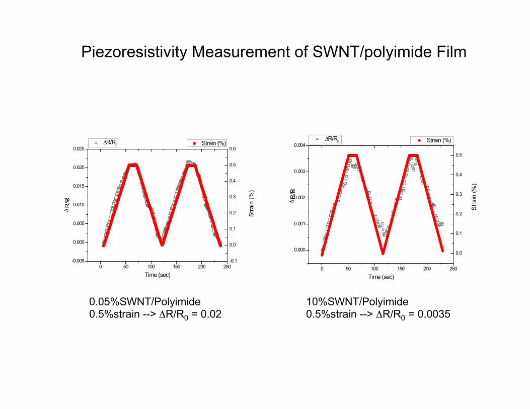
0.05%SWNT/Polyimide0.5%strain --> ΔR/R0 = 0.02
10%SWNT/Polyimide0.5%strain --> ΔR/R0 = 0.0035
Piezoresistivity Measurement of SWNT/polyimide Film
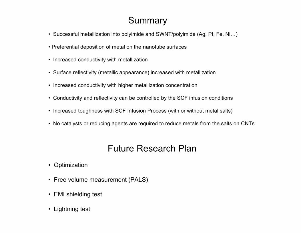
• Successful metallization into polyimide and SWNT/polyimide (Ag, Pt, Fe, Ni…)
• Preferential deposition of metal on the nanotube surfaces
• Increased conductivity with metallization
• Surface reflectivity (metallic appearance) increased with metallization
• Increased conductivity with higher metallization concentration
• Conductivity and reflectivity can be controlled by the SCF infusion conditions
• Increased toughness with SCF Infusion Process (with or without metal salts)
• No catalysts or reducing agents are required to reduce metals from the salts on CNTs
Summary
• Optimization
• Free volume measurement (PALS)
• EMI shielding test
• Lightning test
Future Research Plan
Acknowledgements for partial support by the NASA University Research,Engineering and Technology Institute (URETI) on BioInspired Materials(BIMat) under Award No. NCC-1-02037
Acknowledgements
NASA Langley Research CenterNancy HollowayAdvanced Materials and Processing Branch
DARPA Revolutionizing ProstheticsDARPA SkyWalker
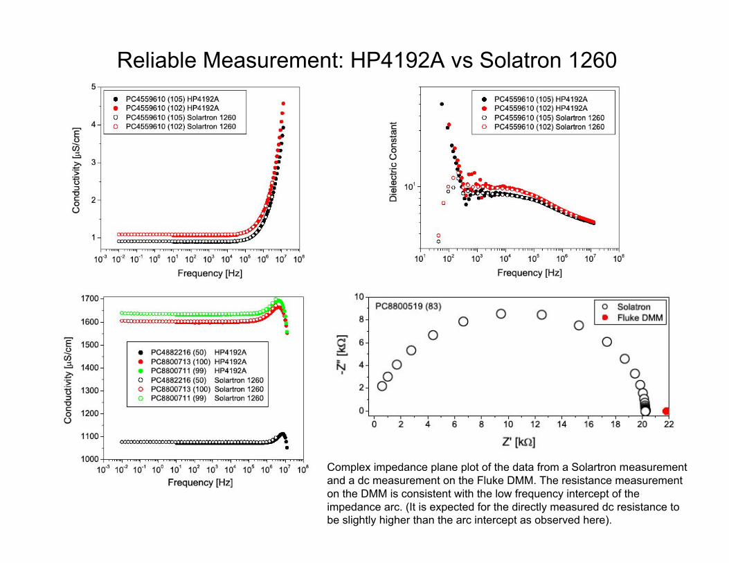
Reliable Measurement: HP4192A vs Solatron 1260
Complex impedance plane plot of the data from a Solartron measurementand a dc measurement on the Fluke DMM. The resistance measurementon the DMM is consistent with the low frequency intercept of theimpedance arc. (It is expected for the directly measured dc resistance tobe slightly higher than the arc intercept as observed here).
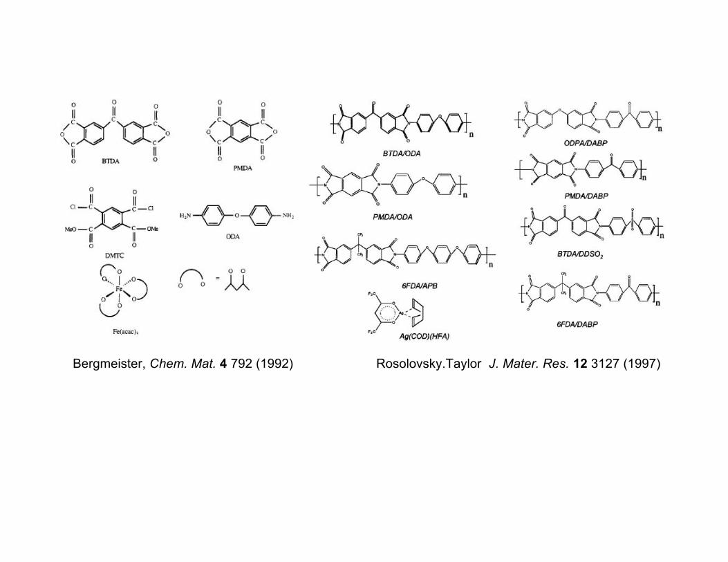
Rosolovsky.Taylor J. Mater. Res. 12 3127 (1997)Bergmeister, Chem. Mat. 4 792 (1992)