
Metal Structures Lecture XII Joints - bolted and welded ...footbridge.pl/stud/z/se1/lec112.pdf ·...
99
Metal Structures Lecture XII Joints - bolted and welded (part I)
Transcript of Metal Structures Lecture XII Joints - bolted and welded ...footbridge.pl/stud/z/se1/lec112.pdf ·...
Metal Structures
Lecture XII
Joints - bolted and welded(part I)
Contents
Joint beam-column → #t / 3
Examples of calculation → #t / 37
Column bases → #t / 78
Support on masonry wall → #t / 95
Examination issues → #t / 97
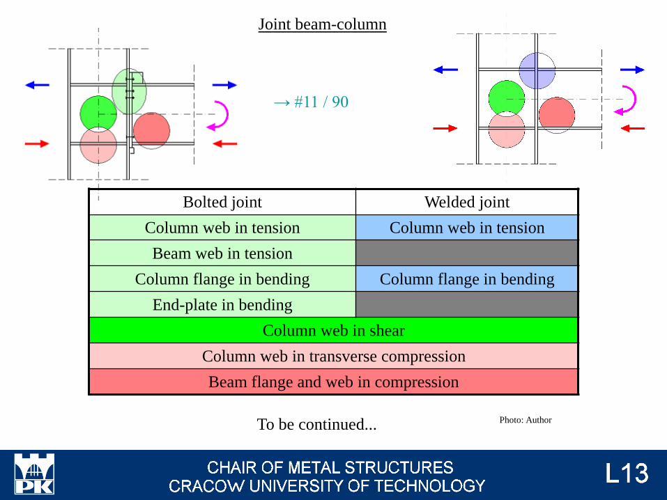
Bolted joint Welded joint
Column web in tension Column web in tension
Beam web in tension
Column flange in bending Column flange in bending
End-plate in bending
Column web in shear
Column web in transverse compression
Beam flange and web in compression
To be continued...
Joint beam-column
→ #11 / 90
Photo: Author
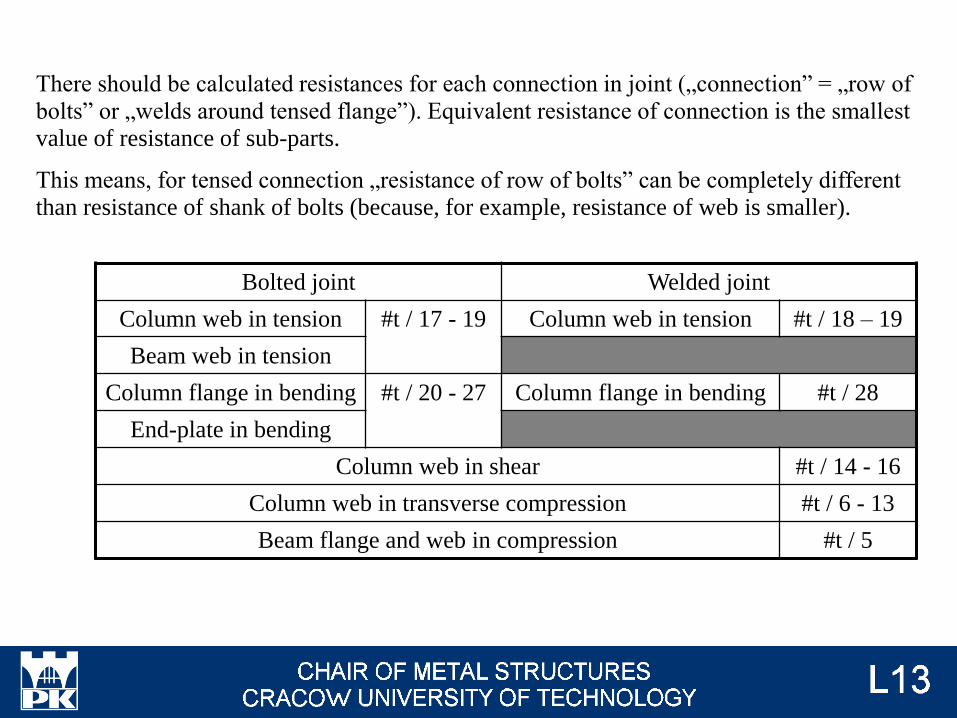
Bolted joint Welded joint
Column web in tension #t / 17 - 19 Column web in tension #t / 18 – 19
Beam web in tension
Column flange in bending #t / 20 - 27 Column flange in bending #t / 28
End-plate in bending
Column web in shear #t / 14 - 16
Column web in transverse compression #t / 6 - 13
Beam flange and web in compression #t / 5
There should be calculated resistances for each connection in joint („connection” = „row of
bolts” or „welds around tensed flange”). Equivalent resistance of connection is the smallest
value of resistance of sub-parts.
This means, for tensed connection „resistance of row of bolts” can be completely different
than resistance of shank of bolts (because, for example, resistance of web is smaller).
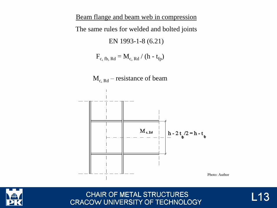
Fc, fb, Rd = Mc, Rd / (h - tfp)
Mc, Rd – resistance of beam
Beam flange and beam web in compression
The same rules for welded and bolted joints
EN 1993-1-8 (6.21)
Photo: Author
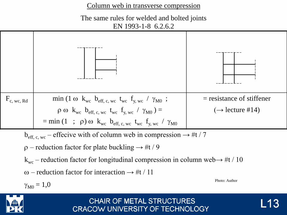
Fc, wc, Rd min (1 w kwc beff, c, wc twc fy, wc / gM0 ;
r w kwc beff, c, wc twc fy, wc / gM0 ) =
= min (1 ; r) w kwc beff, c, wc twc fy, wc / gM0
= resistance of stiffener
(→ lecture #14)
Column web in transverse compression
The same rules for welded and bolted joints
EN 1993-1-8 6.2.6.2
beff, c, wc – effecive with of column web in compression → #t / 7
r – reduction factor for plate buckling → #t / 9
kwc – reduction factor for longitudinal compression in column web→ #t / 10
w – reduction factor for interaction → #t / 11
gM0 = 1,0Photo: Author
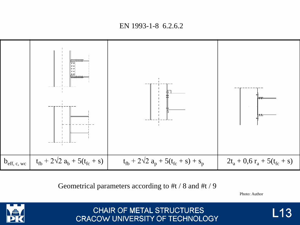
beff, c, wc tfb + 2√2 ab + 5(tfc + s) tfb + 2√2 ap + 5(tfc + s) + sp 2ta + 0,6 ra + 5(tfc + s)
Geometrical parameters according to #t / 8 and #t / 9
EN 1993-1-8 6.2.6.2
Photo: Author
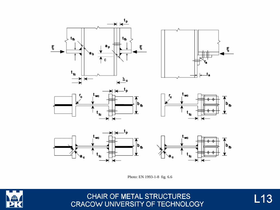
Photo: EN 1993-1-8 fig. 6.6
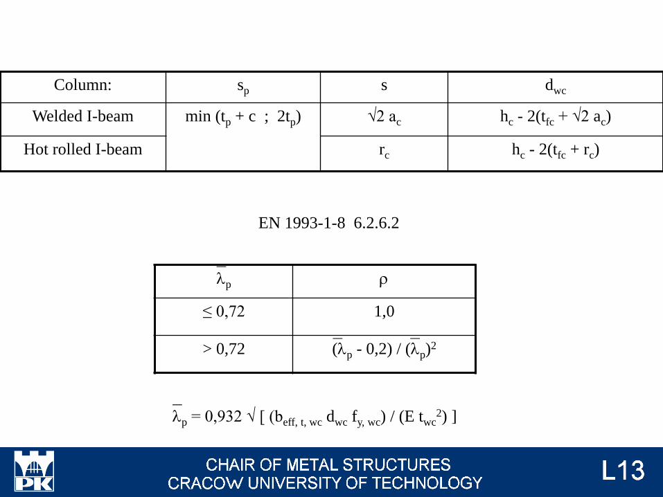
Column: sp s dwc
Welded I-beam min (tp + c ; 2tp) √2 ac hc - 2(tfc + √2 ac)
Hot rolled I-beam rc hc - 2(tfc + rc)
lp = 0,932 √ [ (beff, t, wc dwc fy, wc) / (E twc2) ]
_
lp r
≤ 0,72 1,0
> 0,72 (lp - 0,2) / (lp)2
_
_ _
EN 1993-1-8 6.2.6.2
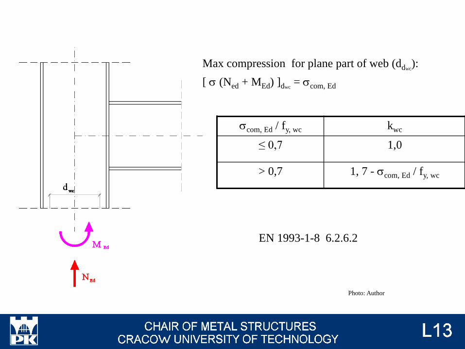
scom, Ed / fy, wc kwc
≤ 0,7 1,0
> 0,7 1, 7 - scom, Ed / fy, wc
Max compression for plane part of web (ddwc):
[ s (Ned + MEd) ]dwc= scom, Ed
EN 1993-1-8 6.2.6.2
Photo: Author
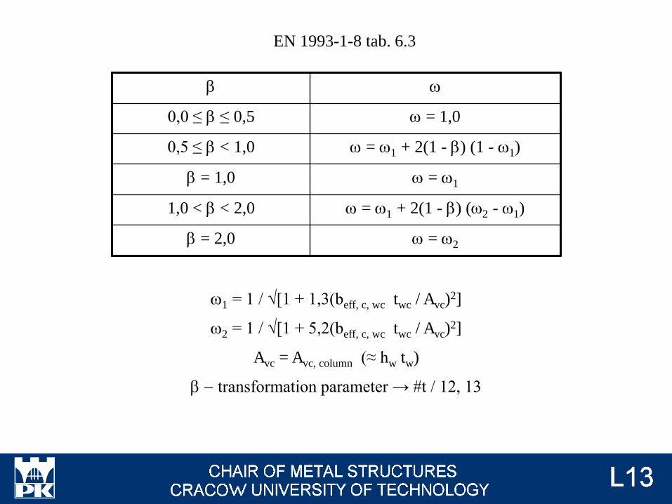
b w
0,0 ≤ b ≤ 0,5 w = 1,0
0,5 ≤ b < 1,0 w = w1 + 2(1 - b) (1 - w1)
b = 1,0 w = w1
1,0 < b < 2,0 w = w1 + 2(1 - b) (w2 - w1)
b = 2,0 w = w2
w1 = 1 / √[1 + 1,3(beff, c, wc twc / Avc)2]
w2 = 1 / √[1 + 5,2(beff, c, wc twc / Avc)2]
Avc = Avc, column (≈ hw tw)
b - transformation parameter → #t / 12, 13
EN 1993-1-8 tab. 6.3
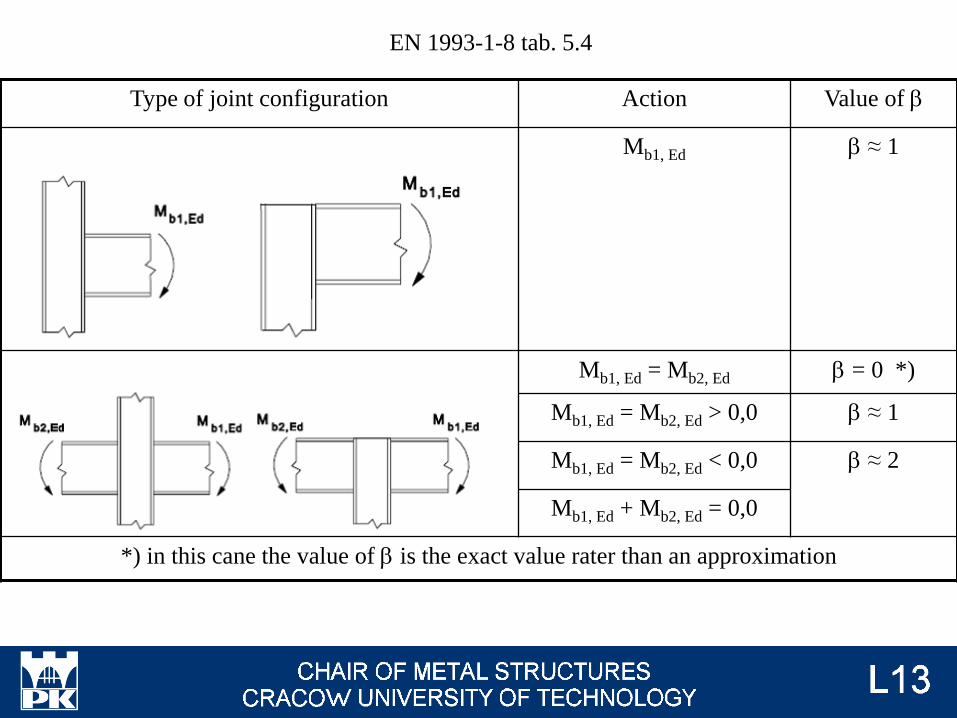
EN 1993-1-8 tab. 5.4
Type of joint configuration Action Value of b
Mb1, Ed b ≈ 1
Mb1, Ed = Mb2, Ed b = 0 *)
Mb1, Ed = Mb2, Ed > 0,0 b ≈ 1
Mb1, Ed = Mb2, Ed < 0,0 b ≈ 2
Mb1, Ed + Mb2, Ed = 0,0
*) in this cane the value of b is the exact value rater than an approximation
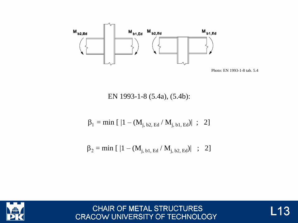
EN 1993-1-8 (5.4a), (5.4b):
b1 = min [ |1 – (Mj, b2, Ed / Mj, b1, Ed)| ; 2]
b2 = min [ |1 – (Mj, b1, Ed / Mj, b2, Ed)| ; 2]
Photo: EN 1993-1-8 tab. 5.4
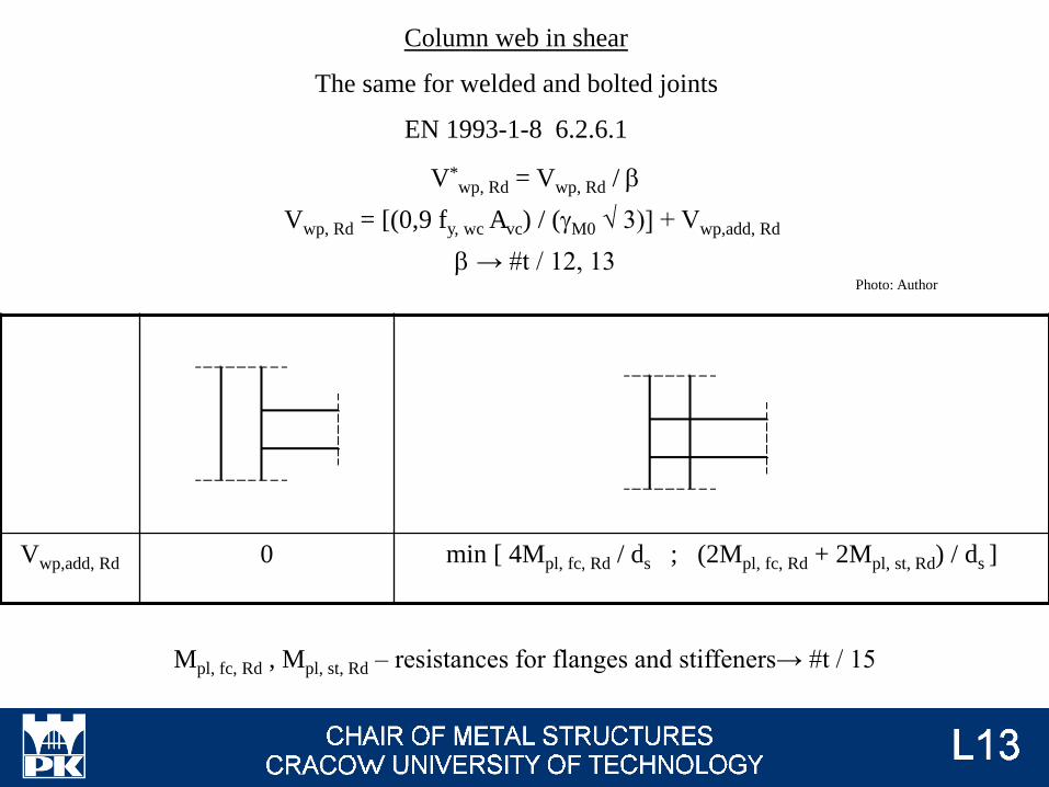
V*wp, Rd = Vwp, Rd / b
Vwp, Rd = [(0,9 fy, wc Avc) / (gM0 √ 3)] + Vwp,add, Rd
b → #t / 12, 13
Vwp,add, Rd 0 min [ 4Mpl, fc, Rd / ds ; (2Mpl, fc, Rd + 2Mpl, st, Rd) / ds ]
Column web in shear
The same for welded and bolted joints
EN 1993-1-8 6.2.6.1
Mpl, fc, Rd , Mpl, st, Rd – resistances for flanges and stiffeners→ #t / 15
Photo: Author
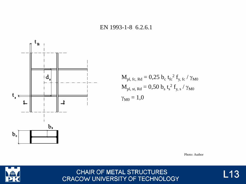
Mpl, fc, Rd = 0,25 bc tfc2 fy, fc / gM0
Mpl, st, Rd = 0,50 bs ts2 fy, s / gM0
gM0 = 1,0
EN 1993-1-8 6.2.6.1
Photo: Author
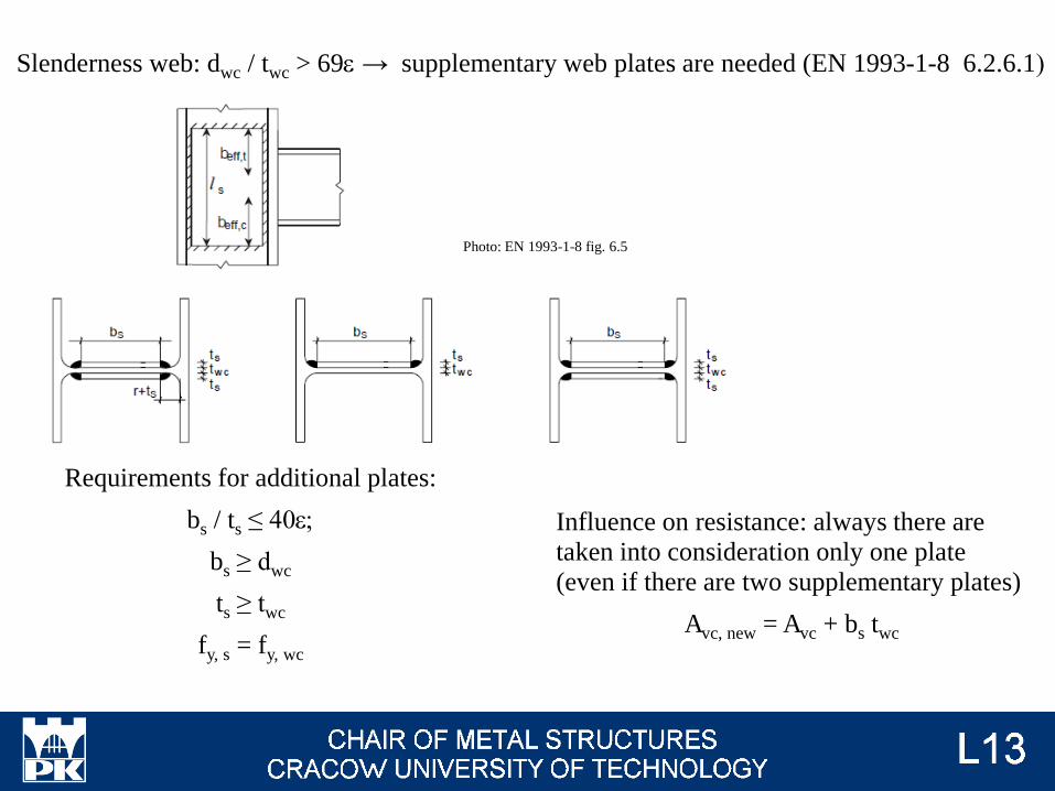
Slenderness web: dwc / twc > 69e → supplementary web plates are needed (EN 1993-1-8 6.2.6.1)
Requirements for additional plates:
bs / ts ≤ 40e;
bs ≥ dwc
ts ≥ twc
fy, s = fy, wc
Influence on resistance: always there are
taken into consideration only one plate
(even if there are two supplementary plates)
Avc, new = Avc + bs twc
Photo: EN 1993-1-8 fig. 6.5
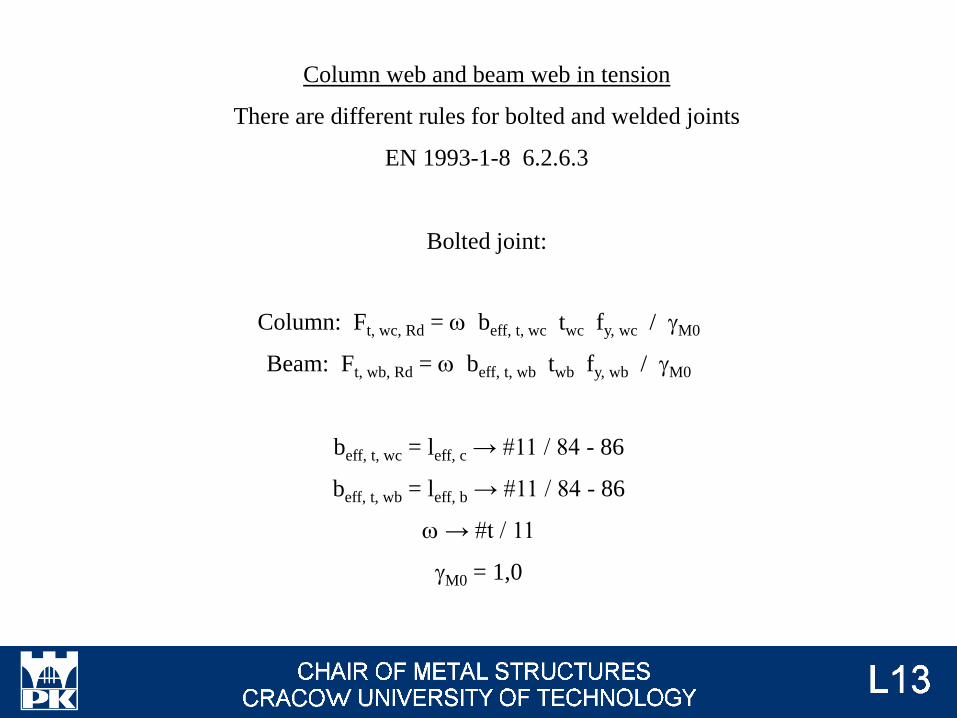
Column: Ft, wc, Rd = w beff, t, wc twc fy, wc / gM0
Beam: Ft, wb, Rd = w beff, t, wb twb fy, wb / gM0
beff, t, wc = leff, c → #11 / 84 - 86
beff, t, wb = leff, b → #11 / 84 - 86
w → #t / 11
gM0 = 1,0
Column web and beam web in tension
There are different rules for bolted and welded joints
EN 1993-1-8 6.2.6.3
Bolted joint:
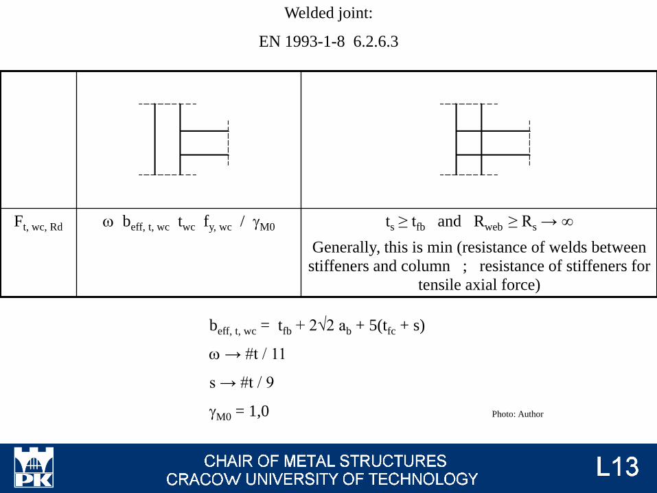
beff, t, wc = tfb + 2√2 ab + 5(tfc + s)
w → #t / 11
s → #t / 9
gM0 = 1,0
Ft, wc, Rd w beff, t, wc twc fy, wc / gM0 ts ≥ tfb and Rweb ≥ Rs → ∞
Generally, this is min (resistance of welds between
stiffeners and column ; resistance of stiffeners for
tensile axial force)
Welded joint:
EN 1993-1-8 6.2.6.3
Photo: Author
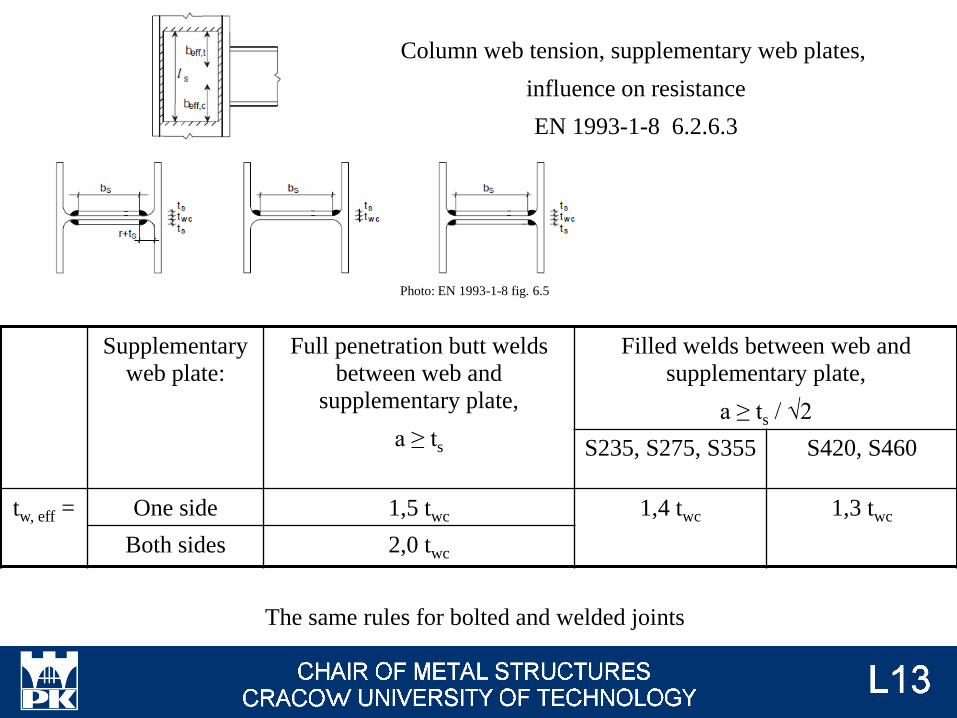
Supplementary
web plate:
Full penetration butt welds
between web and
supplementary plate,
a ≥ ts
Filled welds between web and
supplementary plate,
a ≥ ts / √2
S235, S275, S355 S420, S460
tw, eff = One side 1,5 twc 1,4 twc 1,3 twc
Both sides 2,0 twc
The same rules for bolted and welded joints
Column web tension, supplementary web plates,
influence on resistance
EN 1993-1-8 6.2.6.3
Photo: EN 1993-1-8 fig. 6.5
Column flange and end plate in bending
There are different rules for bolted and welded joints
Bolted joint:
We must analyse three different mechanism of destruction,
according to prying actions phenomenon
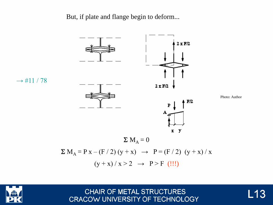
S MA = 0
S MA = P x – (F / 2) (y + x) → P = (F / 2) (y + x) / x
(y + x) / x > 2 → P > F (!!!)
But, if plate and flange begin to deform...
Photo: Author
→ #11 / 78
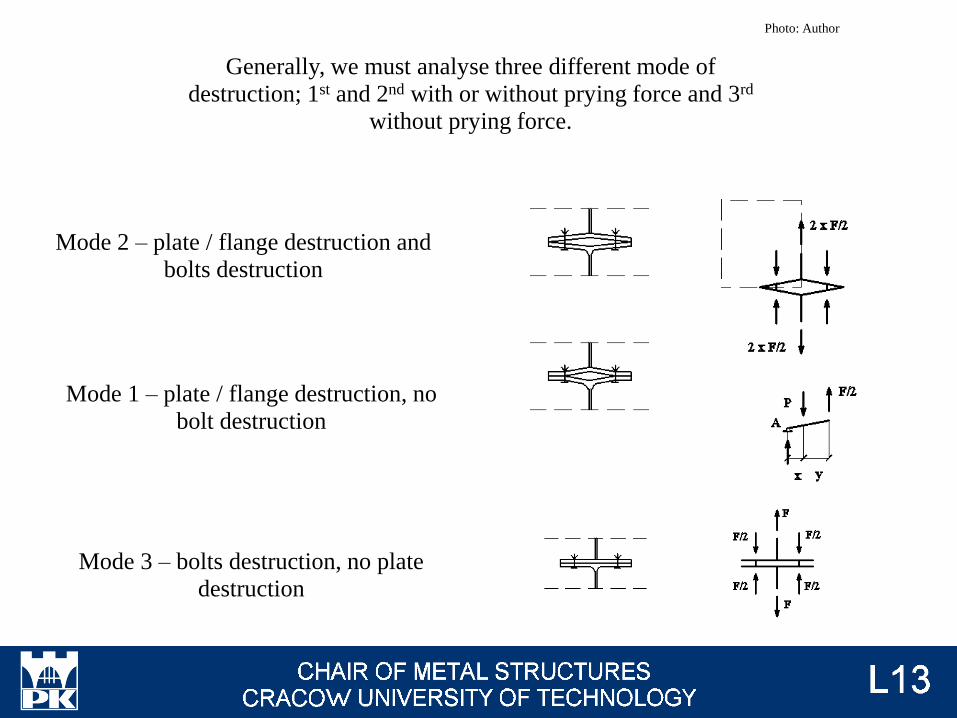
Mode 1 – plate / flange destruction, no
bolt destruction
Mode 2 – plate / flange destruction and
bolts destruction
Mode 3 – bolts destruction, no plate
destruction
Generally, we must analyse three different mode of
destruction; 1st and 2nd with or without prying force and 3rd
without prying force.
Photo: Author
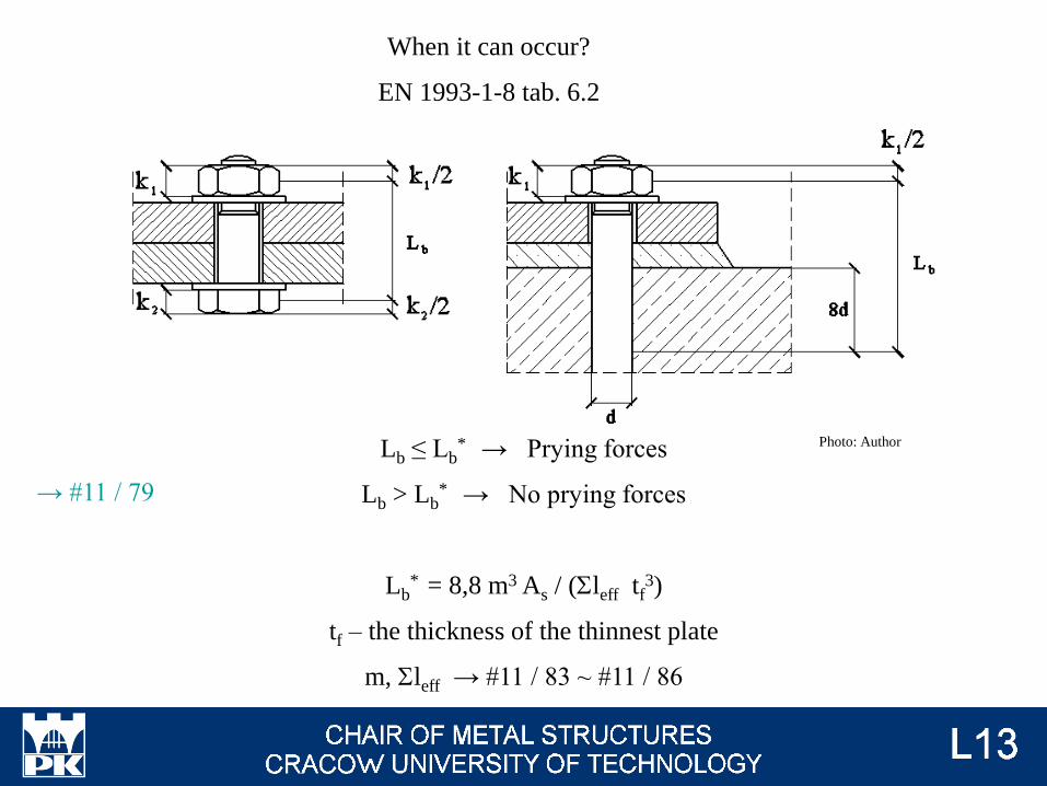
Lb ≤ Lb* → Prying forces
Lb > Lb* → No prying forces
Lb* = 8,8 m3 As / (Sleff tf
3)
tf – the thickness of the thinnest plate
m, Sleff → #11 / 83 ~ #11 / 86
When it can occur?
EN 1993-1-8 tab. 6.2
Photo: Author
→ #11 / 79
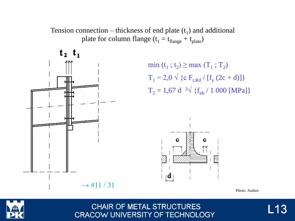
min (t1 ; t2) ≥ max (T1 ; T2)
T1 = 2,0 √ {c Ft,Rd / [fy (2c + d)]}
T2 = 1,67 d 3√ {fub / 1 000 [MPa]}
Tension connection – thickness of end plate (t1) and additional
plate for column flange (t1 = tflange + tplate)
Photo: Author → #11 / 31
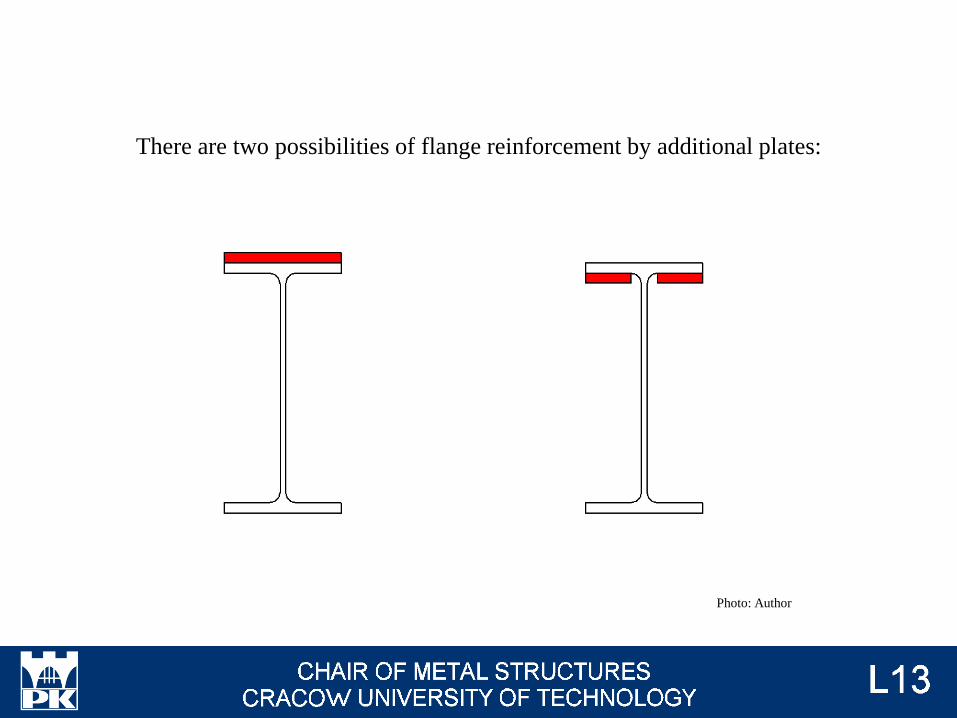
There are two possibilities of flange reinforcement by additional plates:
Photo: Author
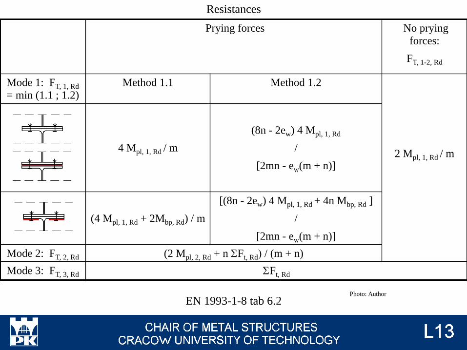
Prying forces No prying
forces:
FT, 1-2, Rd
Mode 1: FT, 1, Rd
= min (1.1 ; 1.2)
Method 1.1 Method 1.2
2 Mpl, 1, Rd / m4 Mpl, 1, Rd / m
(8n - 2ew) 4 Mpl, 1, Rd
/
[2mn - ew(m + n)]
(4 Mpl, 1, Rd + 2Mbp, Rd) / m
[(8n - 2ew) 4 Mpl, 1, Rd + 4n Mbp, Rd ]
/
[2mn - ew(m + n)]
Mode 2: FT, 2, Rd (2 Mpl, 2, Rd + n SFt, Rd) / (m + n)
Mode 3: FT, 3, Rd SFt, Rd
EN 1993-1-8 tab 6.2
Resistances
Photo: Author
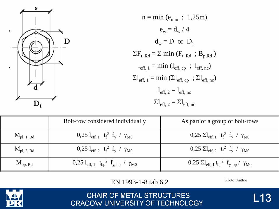
n = min (emin ; 1,25m)
ew = dw / 4
dw = D or D1
SFt, Rd = S min (Ft, Rd ; Bp,Rd )
leff, 1 = min (leff, cp ; leff, nc)
Sleff, 1 = min (Sleff, cp ; Sleff, nc)
leff, 2 = leff, nc
Sleff, 2 = Sleff, nc
Bolt-row considered individually As part of a group of bolt-rows
Mpl, 1, Rd 0,25 leff, 1 tf2 fy / gM0 0,25 Sleff, 1 tf
2 fy / gM0
Mpl, 2, Rd 0,25 leff, 2 tf2 fy / gM0 0,25 Sleff, 2 tf
2 fy / gM0
Mbp, Rd 0,25 leff, 1 tbp2 fy, bp / gM0 0,25 Sleff, 1 tbp
2 fy, bp / gM0
EN 1993-1-8 tab 6.2 Photo: Author

Welded joint
beff, t, fc = twc + 2s + 7 k tf
k = min [ (tf / tp)(fy, f / fy, p) ; 1,0 ]
Ft, wc, Rd beff, b, fc tfc fy, fc / gM0 ts ≥ tfb and Rweb ≥ Rs → ∞
Generally, this is min (resistance of welds between
stiffeners and column ; resistance of stiffeners for
tensile axial force)
EN 1993-1-8 4.10 Photo: Author
Resistance of joint:
Generally:
Resistance of joint = S (equivalent resistance of connection ∙ arm action)
equivalent resistance of connection = the lowest value for resistance from each parts of
joint
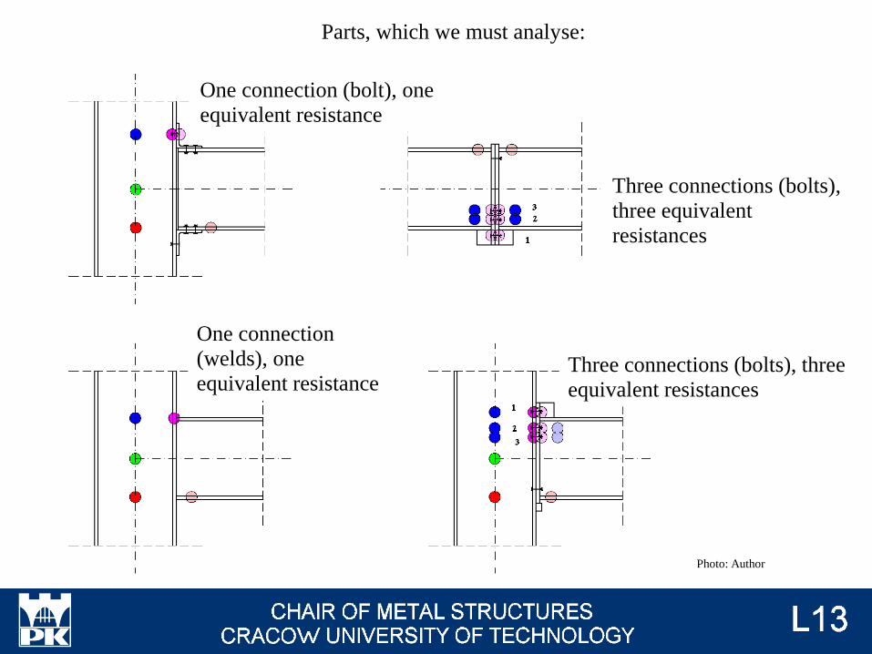
Parts, which we must analyse:
Photo: Author
One connection (bolt), one
equivalent resistance
One connection
(welds), one
equivalent resistance
Three connections (bolts),
three equivalent
resistances
Three connections (bolts), three
equivalent resistances
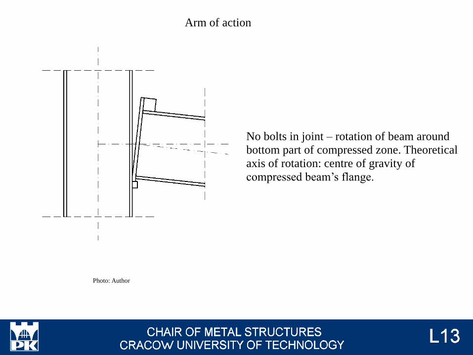
Arm of action
Photo: Author
No bolts in joint – rotation of beam around
bottom part of compressed zone. Theoretical
axis of rotation: centre of gravity of
compressed beam’s flange.
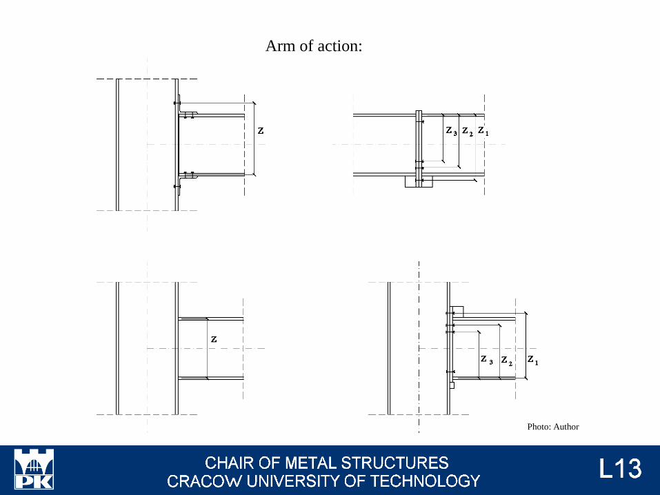
Arm of action:
Photo: Author
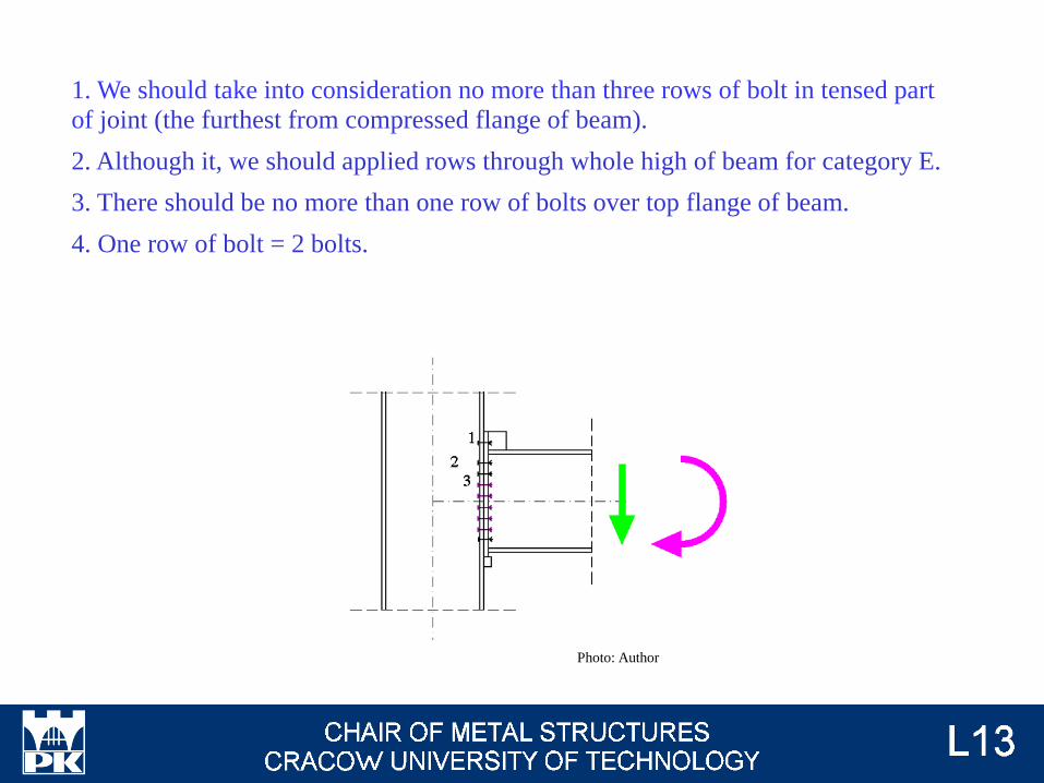
1. We should take into consideration no more than three rows of bolt in tensed part
of joint (the furthest from compressed flange of beam).
2. Although it, we should applied rows through whole high of beam for category E.
3. There should be no more than one row of bolts over top flange of beam.
4. One row of bolt = 2 bolts.
Photo: Author

There are four main types of bolted joint for beam-column joint:
Photo: steelconstruction.info
Photo: uwyo.edu
Photo: lusas.comPhoto: gic-edu.com

Full depth end plate ↔ extended end plate → different formulas for leff (→ #11 / 84 - 86);
Stiffened depth end plate → application of additional vertical stiffener is recommended
(greated resistance and stiffness of joint);
Haunched beam → greated resistance and stiffness of joint (→ #t / 76);
Photo: Author
leff
leff
leff
There is possible, that effective areas from two
row of bolts would be common. In this situation
we must analysed group of bolts, not separate
bolts. But, on the other hand, if there is any
horizontal plate (flange, stiffeners) between
rows of bolts, these rows are completely
separated. In this case we not taken into
consideration group, only separated bolts.
First (the higher) row of bolt is always analysed
as separated row only.
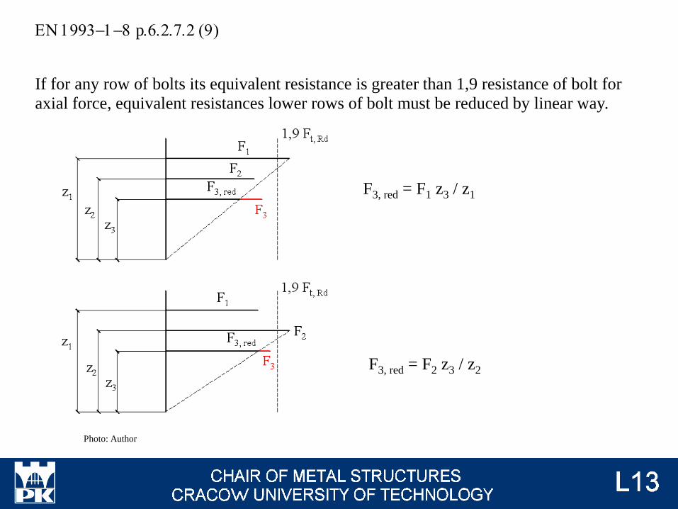
EN 1993-1-8 p.6.2.7.2 (9)
If for any row of bolts its equivalent resistance is greater than 1,9 resistance of bolt for
axial force, equivalent resistances lower rows of bolt must be reduced by linear way.
Photo: Author
F3, red = F1 z3 / z1
F3, red = F2 z3 / z2
Examples of calculation Photo: Author
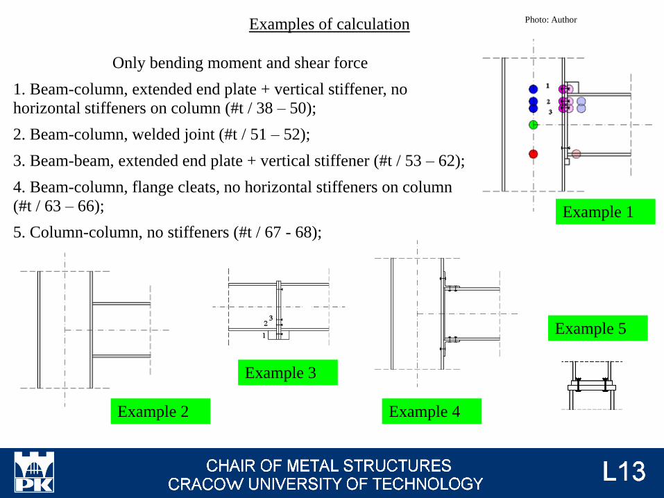
Only bending moment and shear force
1. Beam-column, extended end plate + vertical stiffener, no
horizontal stiffeners on column (#t / 38 – 50);
2. Beam-column, welded joint (#t / 51 – 52);
3. Beam-beam, extended end plate + vertical stiffener (#t / 53 – 62);
4. Beam-column, flange cleats, no horizontal stiffeners on column
(#t / 63 – 66);
5. Column-column, no stiffeners (#t / 67 - 68);
Example 1
Example 2
Example 3
Example 4
Example 5
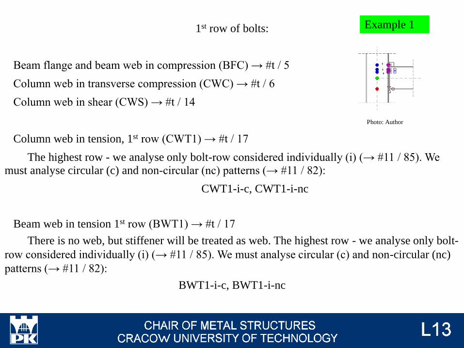
1st row of bolts:
Beam flange and beam web in compression (BFC) → #t / 5
Column web in transverse compression (CWC) → #t / 6
Column web in shear (CWS) → #t / 14
Column web in tension, 1st row (CWT1) → #t / 17
The highest row - we analyse only bolt-row considered individually (i) (→ #11 / 85). We
must analyse circular (c) and non-circular (nc) patterns (→ #11 / 82):
CWT1-i-c, CWT1-i-nc
Beam web in tension 1st row (BWT1) → #t / 17
There is no web, but stiffener will be treated as web. The highest row - we analyse only bolt-
row considered individually (i) (→ #11 / 85). We must analyse circular (c) and non-circular (nc)
patterns (→ #11 / 82):
BWT1-i-c, BWT1-i-nc
Example 1
Photo: Author
1st row of bolts continuation:
Column flange in bending 1st row (CFB1) → #t / 20:
The highers row - we analyse only bolt-row considered individually (i) (→ #11 / 85). We
must analyse circular (c) and non-circular (nc) patterns (→ #11 / 82). We must analyse three
different mechanism of flange destruction (1, 2, 3) (→ #t / 26):
CFB1-i-c-1, CFB1-i-c-2, CFB1-i-c-3,
CFB1-i-nc-1, CFB1-i-nc-2, CFB1-i-nc-3
End-plate in bending 1st row (EB1) → #t / 20:
The highest row - we analyse only bolt-row considered individually (i) (→ #11 / 84). We
must analyse circular (c) and non-circular (nc) patterns (→ #11 / 82). We must analyse three
different mechanism of plate destruction (1, 2, 3) (→ #t / 26):
EB1-i-c-1, EB1-i-c-2, EB1-i-c-3,
EB1-i-nc-1, EB1-i-nc-2, EB1-i-nc-3
1st row of bolts continuation:
Resistance for first bolt-row – the smallest value among 19:
1BR = min ( BFC ; CWC ; CWS ; CWT1-i-c ; CWT1-i-nc ; BWT1-i-c ; BWT1-i-nc ;
CFB1-i-c-1 ; CFB1-i-c-2 ; CFB1-i-c-3 ; CFB1-i-nc-1 ; CFB1-i-nc-2 ; CFB1-i-nc-3 ;
EB1-i-c-1 ; EB1-i-c-2 ; EB1-i-c-3 ; EB1-i-nc-1 ; EB1-i-nc-2 ; EB1-i-nc-3 )
2nd row of bolts:
Beam flange and beam web in compression (BFC) → the same as for 1st row
Column web in transverse compression (CWC) → the same as for 1st row
Column web in shear (CWS) → the same as for 1st row
Column web in tension, 2nd row (CWT2) → #t / 17
No horizontal stiffeners on column web - we analyse bolt-row considered individually (i)
and as part of a group of 1st and 2nd bolt-rows (12g) (→ #11 / 85). We must analyse circular (c)
and non-circular (nc) patterns (→ #11 / 82):
CWT2-i-c, CWT2-i-nc
CWT2-12g-c, CWT2-12g-nc
Beam web in tension 2nd row (BWT2) → #t / 17
There is beam flange between 1st and 2nd row, these rows are separated each other. We
analyse only bolt-row considered individually (i) (→ #11 / 84). We must analyse circular (c) and
non-circular (nc) patterns (→ #11 / 82):
BWT2-i-c, BWT2-i-nc
2nd row of bolts continuation:
Column flange in bending 2nd row (CFB2) → #t / 20:
No horizontal stiffeners on column web - we analyse bolt-row considered individually (i)
and as part of a group of 1st and 2nd bolt-rows (12g) (→ #11 / 85). We must analyse circular (c)
and non-circular (nc) patterns (→ #11 / 82). We must analyse three different mechanism of flange
destruction (1, 2, 3) (→ #t / 26):
CFB2-i-c-1, CFB2-i-c-2, CFB2-i-c-3,
CFB2-i-nc-1, CFB2-i-nc-2, CFB2-i-nc-3
CFB2-12g-c-1, CFB2-12g -c-2, CFB2-12g -c-3,
CFB2-12g -nc-1, CFB2-12g -nc-2, CFB2-12g -nc-3

2nd row of bolts continuation:
End-plate in bending 2nd row (EB2) → #t / 20:
There is beam flange between 1st and 2nd row, these rows are separated each other. We
analyse only bolt-row considered individually (i) (→ #11 / 84). We must analyse circular (c) and
non-circular (nc) patterns (→ #11 / 82). We must analyse three different mechanism of plate
destruction (1, 2, 3) (→ #t / 26):
EB2-i-c-1, EB2-i-c-2, EB2-i-c-3,
EB2-i-nc-1, EB2-i-nc-2, EB2-i-nc-3
2nd row of bolts continuation:
Resistance for second bolt-row – the smallest value among 27:
2BR = min [ BFC ; CWC ; CWS ; CWT2-i-c ; CWT2-i-nc ;
( CWT2-12g-c – 1RB ) ; ( CWT2-12g-nc – 1RB ) ; BWT2-i-c ; BWT2-i-nc ;
CFB2-i-c-1 ; CFB2-i-c-2 ; CFB2-i-c-3 ; CFB2-i-nc-1 ; CFB2-i-nc-2 ; CFB2-i-nc-3 ;
( CFB2-12g-c-1- 1RB) ; ( CFB2-12g -c-2 – 1RB) ; ( CFB2-12g -c-3 – 1RB) ;
( CFB2-12g -nc-1 – 1RB) ; ( CFB2-12g -nc-2 – 1RB) ; ( CFB2-12g -nc-3 – 1 RB) ;
EB2-i-c-1 ; EB2-i-c-2 ; EB2-i-c-3 ; EB2-i-nc-1 ; EB2-i-nc-2 ; EB2-i-nc-3 ]
3rd row of bolts:
Beam flange and beam web in compression (BFC) → the same as for 1st row
Column web in transverse compression (CWC) → the same as for 1st row
Column web in shear (CWS) → the same as for 1st row
Column web in tension, 3rd row (CWT3) → #t / 17
No horizontal stiffeners on column web - we analyse bolt-row considered individually (i)
and as part of a group of 2nd and 3rd bolt-rows (23g) and as part of a group of 1st, 2nd and 3rd bolt-
rows (123g) (→ #11 / 85). We must analyse circular (c) and non-circular (nc) patterns (→ #11 /
82):
CWT3-i-c, CWT3-i-nc
CWT3-23g-c, CWT3-23g-nc
CWT3-123g-c, CWT3-123g-nc

3rd row of bolts continuation:
Beam web in tension 3rd row (BWT3) → #t / 17
There is beam flange between 1st and 2nd row, these rows are separated each other. There is
no separating element for 2nd and 3rd row. We analyse only bolt-row considered individually (i)
and as part of a group of 2nd and 3rd bolt-rows (23g) (→ #11 / 84). We must analyse circular (c)
and non-circular (nc) patterns (→ #11 / 82):
BWT3-i-c, BWT3-i-nc
BWT3-23g-c, BWT3-23g-nc
3rd row of bolts continuation:
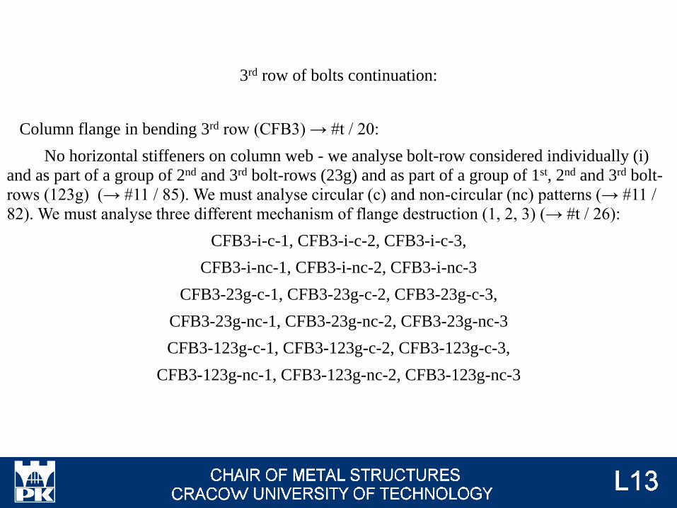
Column flange in bending 3rd row (CFB3) → #t / 20:
No horizontal stiffeners on column web - we analyse bolt-row considered individually (i)
and as part of a group of 2nd and 3rd bolt-rows (23g) and as part of a group of 1st, 2nd and 3rd bolt-
rows (123g) (→ #11 / 85). We must analyse circular (c) and non-circular (nc) patterns (→ #11 /
82). We must analyse three different mechanism of flange destruction (1, 2, 3) (→ #t / 26):
CFB3-i-c-1, CFB3-i-c-2, CFB3-i-c-3,
CFB3-i-nc-1, CFB3-i-nc-2, CFB3-i-nc-3
CFB3-23g-c-1, CFB3-23g-c-2, CFB3-23g-c-3,
CFB3-23g-nc-1, CFB3-23g-nc-2, CFB3-23g-nc-3
CFB3-123g-c-1, CFB3-123g-c-2, CFB3-123g-c-3,
CFB3-123g-nc-1, CFB3-123g-nc-2, CFB3-123g-nc-3
3rd row of bolts continuation:
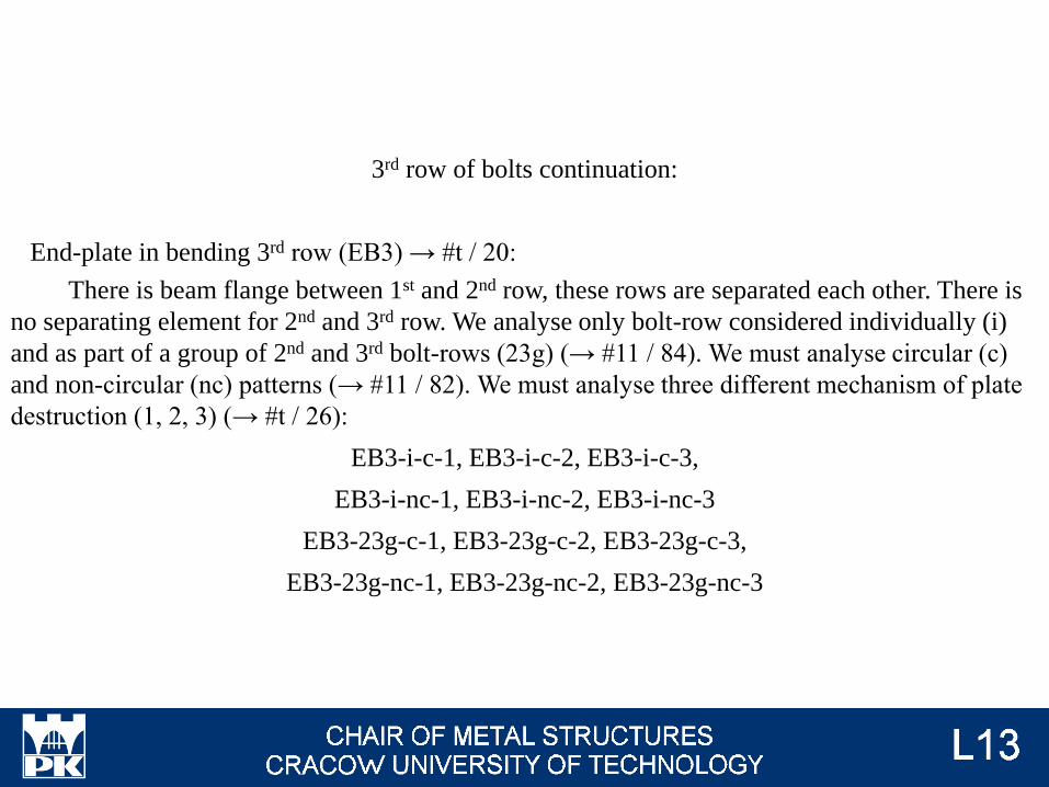
End-plate in bending 3rd row (EB3) → #t / 20:
There is beam flange between 1st and 2nd row, these rows are separated each other. There is
no separating element for 2nd and 3rd row. We analyse only bolt-row considered individually (i)
and as part of a group of 2nd and 3rd bolt-rows (23g) (→ #11 / 84). We must analyse circular (c)
and non-circular (nc) patterns (→ #11 / 82). We must analyse three different mechanism of plate
destruction (1, 2, 3) (→ #t / 26):
EB3-i-c-1, EB3-i-c-2, EB3-i-c-3,
EB3-i-nc-1, EB3-i-nc-2, EB3-i-nc-3
EB3-23g-c-1, EB3-23g-c-2, EB3-23g-c-3,
EB3-23g-nc-1, EB3-23g-nc-2, EB3-23g-nc-3
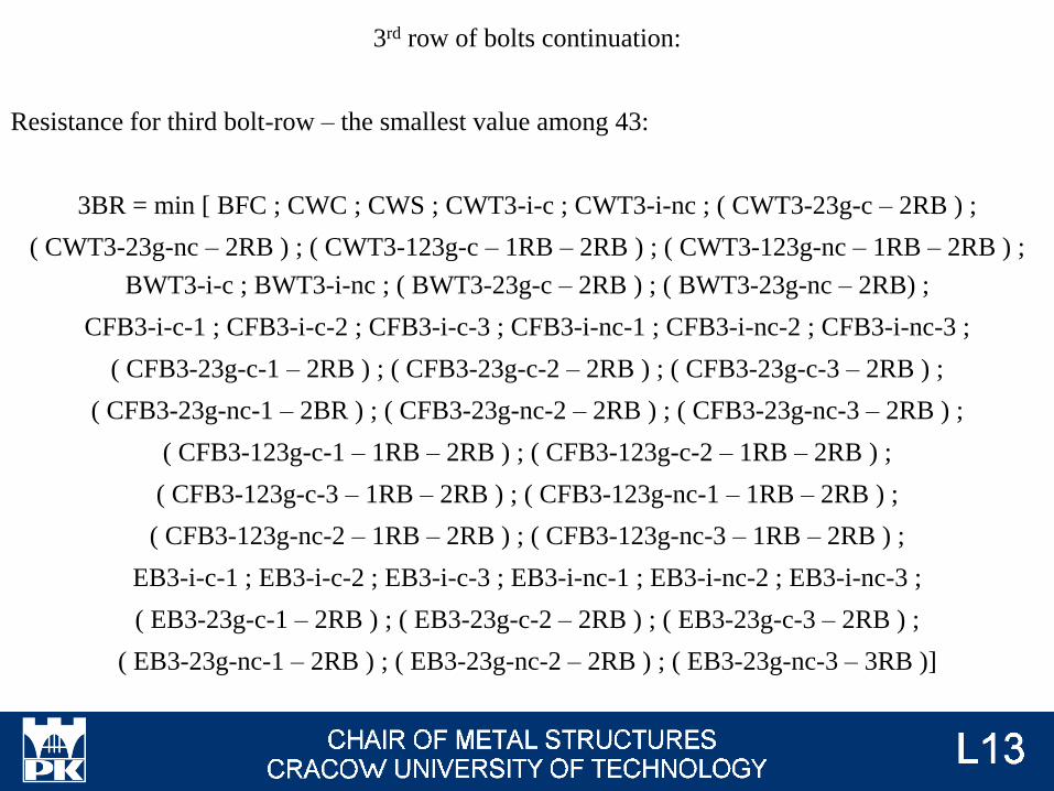
3rd row of bolts continuation:
Resistance for third bolt-row – the smallest value among 43:
3BR = min [ BFC ; CWC ; CWS ; CWT3-i-c ; CWT3-i-nc ; ( CWT3-23g-c – 2RB ) ;
( CWT3-23g-nc – 2RB ) ; ( CWT3-123g-c – 1RB – 2RB ) ; ( CWT3-123g-nc – 1RB – 2RB ) ;
BWT3-i-c ; BWT3-i-nc ; ( BWT3-23g-c – 2RB ) ; ( BWT3-23g-nc – 2RB) ;
CFB3-i-c-1 ; CFB3-i-c-2 ; CFB3-i-c-3 ; CFB3-i-nc-1 ; CFB3-i-nc-2 ; CFB3-i-nc-3 ;
( CFB3-23g-c-1 – 2RB ) ; ( CFB3-23g-c-2 – 2RB ) ; ( CFB3-23g-c-3 – 2RB ) ;
( CFB3-23g-nc-1 – 2BR ) ; ( CFB3-23g-nc-2 – 2RB ) ; ( CFB3-23g-nc-3 – 2RB ) ;
( CFB3-123g-c-1 – 1RB – 2RB ) ; ( CFB3-123g-c-2 – 1RB – 2RB ) ;
( CFB3-123g-c-3 – 1RB – 2RB ) ; ( CFB3-123g-nc-1 – 1RB – 2RB ) ;
( CFB3-123g-nc-2 – 1RB – 2RB ) ; ( CFB3-123g-nc-3 – 1RB – 2RB ) ;
EB3-i-c-1 ; EB3-i-c-2 ; EB3-i-c-3 ; EB3-i-nc-1 ; EB3-i-nc-2 ; EB3-i-nc-3 ;
( EB3-23g-c-1 – 2RB ) ; ( EB3-23g-c-2 – 2RB ) ; ( EB3-23g-c-3 – 2RB ) ;
( EB3-23g-nc-1 – 2RB ) ; ( EB3-23g-nc-2 – 2RB ) ; ( EB3-23g-nc-3 – 3RB )]
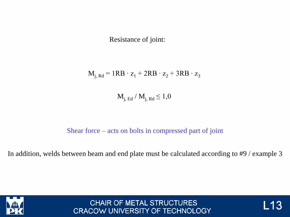
Mj, Rd = 1RB ∙ z1 + 2RB ∙ z2 + 3RB ∙ z3
Mj, Ed / Mj, Rd ≤ 1,0
Shear force – acts on bolts in compressed part of joint
In addition, welds between beam and end plate must be calculated according to #9 / example 3
Resistance of joint:
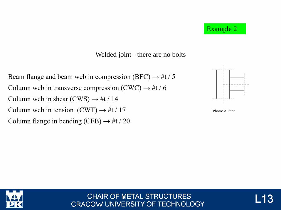
Welded joint - there are no bolts
Beam flange and beam web in compression (BFC) → #t / 5
Column web in transverse compression (CWC) → #t / 6
Column web in shear (CWS) → #t / 14
Column web in tension (CWT) → #t / 17
Column flange in bending (CFB) → #t / 20
Example 2
Photo: Author
R = min (BFC ; CWC ; CWS ; CWT ; CFB )
Mj, Rd = R ∙ z
Mj, Ed / Mj, Rd ≤ 1,0
In addition, welds must be calculated according to #9 / example 3
Resistance of joint:
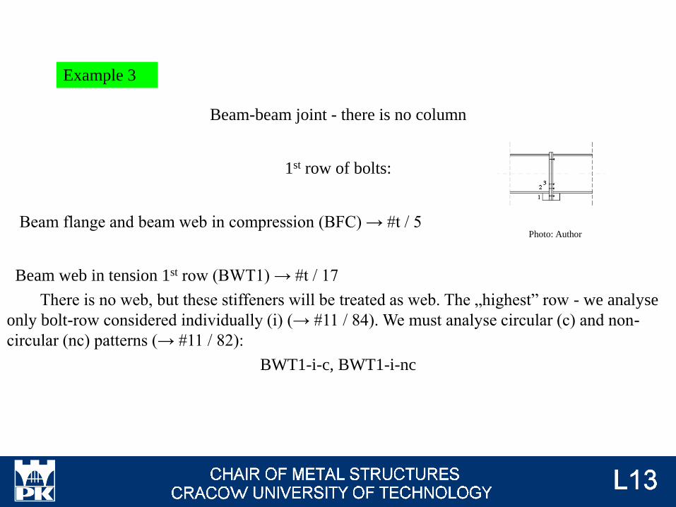
Beam-beam joint - there is no column
1st row of bolts:
Beam flange and beam web in compression (BFC) → #t / 5
Beam web in tension 1st row (BWT1) → #t / 17
There is no web, but these stiffeners will be treated as web. The „highest” row - we analyse
only bolt-row considered individually (i) (→ #11 / 84). We must analyse circular (c) and non-
circular (nc) patterns (→ #11 / 82):
BWT1-i-c, BWT1-i-nc
Example 3
Photo: Author
1st row of bolts continuation:
End-plate in bending 1st row (EB1) → #t / 20:
The „highest” row - we analyse only bolt-row considered individually (i) (→ #11 / 84). We
must analyse circular (c) and non-circular (nc) patterns (→ #11 / 82). We must analyse three
different mechanism of plate destruction (1, 2, 3) (→ #t / 26):
EB1-i-c-1, EB1-i-c-2, EB1-i-c-3,
EB1-i-nc-1, EB1-i-nc-2, EB1-i-nc-3
1st row of bolts continuation:
Resistance for first bolt-row:
1BR = min ( BFC ; BWT1-i-c ; BWT1-i-nc ;
EB1-i-c-1 ; EB1-i-c-2 ; EB1-i-c-3 ; EB1-i-nc-1 ; EB1-i-nc-2 ; EB1-i-nc-3 )
2nd row of bolts:
Beam flange and beam web in compression (BFC) → the same as for 1st row
Beam web in tension 2nd row (BWT2) → #t / 17
There is beam flange between 1st and 2nd row, these rows are separated each other. We
analyse only bolt-row considered individually (i) (→ #11 / 84). We must analyse circular (c) and
non-circular (nc) patterns (→ #11 / 82):
BWT2-i-c, BWT2-i-nc
2nd row of bolts continuation:
End-plate in bending 2nd row (EB2) → #t / 20:
There is beam flange between 1st and 2nd row, these rows are separated each other. We
analyse only bolt-row considered individually (i) (→ #11 / 84). We must analyse circular (c) and
non-circular (nc) patterns (→ #11 / 82). We must analyse three different mechanism of plate
destruction (1, 2, 3) (→ #t / 26):
EB2-i-c-1, EB2-i-c-2, EB2-i-c-3,
EB2-i-nc-1, EB2-i-nc-2, EB2-i-nc-3
2nd row of bolts continuation:
Resistance for second bolt-row:
2BR = min [ BFC ; BWT2-i-c ; BWT2-i-nc ;
EB2-i-c-1 ; EB2-i-c-2 ; EB2-i-c-3 ; EB2-i-nc-1 ; EB2-i-nc-2 ; EB2-i-nc-3 ]
3rd row of bolts:
Beam flange and beam web in compression (BFC) → the same as for 1st row
Beam web in tension 3rd row (BWT3) → #t / 17
There is beam flange between 1st and 2nd row, these rows are separated each other. There is
no separating element for 2nd and 3rd row. We analyse only bolt-row considered individually (i)
and as part of a group of 2nd and 3rd bolt-rows (23g) (→ #11 / 84). We must analyse circular (c)
and non-circular (nc) patterns (→ #11 / 82):
BWT3-i-c, BWT3-i-nc
BWT3-23g-c, BWT3-23g-nc
3rd row of bolts continuation:
End-plate in bending 3rd row (EB3) → #t / 20:
There is beam flange between 1st and 2nd row, these rows are separated each other. There is
no separating element for 2nd and 3rd row. We analyse only bolt-row considered individually (i)
and as part of a group of 2nd and 3rd bolt-rows (23g) (→ #11 / 84). We must analyse circular (c)
and non-circular (nc) patterns (→ #11 / 82). We must analyse three different mechanism of plate
destruction (1, 2, 3) (→ #t / 26):
EB3-i-c-1, EB3-i-c-2, EB3-i-c-3,
EB3-i-nc-1, EB3-i-nc-2, EB3-i-nc-3
EB3-23g-c-1, EB3-23g-c-2, EB3-23g-c-3,
EB3-23g-nc-1, EB3-23g-nc-2, EB3-23g-nc-3
3rd row of bolts continuation:
Resistance for third bolt-row:
3BR = min [ BFC ; BWT3-i-c ; BWT3-i-nc ; ( BWT3-23g-c – 2RB ) ; ( BWT3-23g-nc – 2RB) ;
EB3-i-c-1 ; EB3-i-c-2 ; EB3-i-c-3 ; EB3-i-nc-1 ; EB3-i-nc-2 ; EB3-i-nc-3 ;
( EB3-23g-c-1 – 2RB ) ; ( EB3-23g-c-2 – 2RB ) ; ( EB3-23g-c-3 – 2RB ) ;
( EB3-23g-nc-1 – 2RB ) ; ( EB3-23g-nc-2 – 2RB ) ; ( EB3-23g-nc-3 – 3RB )]
Mj, Rd = 1RB ∙ z1 + 2RB ∙ z2 + 3RB ∙ z3
Mj, Ed / Mj, Rd ≤ 1,0
Shear force – acts on bolts in compressed part of joint
In addition, welds must be calculated according to #9 / example 3
Resistance of joint:
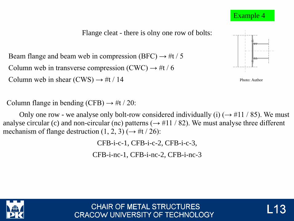
Flange cleat - there is olny one row of bolts:
Beam flange and beam web in compression (BFC) → #t / 5
Column web in transverse compression (CWC) → #t / 6
Column web in shear (CWS) → #t / 14
Column flange in bending (CFB) → #t / 20:
Only one row - we analyse only bolt-row considered individually (i) (→ #11 / 85). We must
analyse circular (c) and non-circular (nc) patterns (→ #11 / 82). We must analyse three different
mechanism of flange destruction (1, 2, 3) (→ #t / 26):
CFB-i-c-1, CFB-i-c-2, CFB-i-c-3,
CFB-i-nc-1, CFB-i-nc-2, CFB-i-nc-3
Example 4
Photo: Author
Flange cleat in bending (FC):
Only one row - we analyse only bolt-row considered individually (i) (→ #11 / 87). We must
analyse circular (c) and non-circular (nc) patterns (→ #11 / 82). We must analyse three different
mechanism of destruction (1, 2, 3) (→ #t / 26):
FC-i-c-1, FC-i-c-2, FC-i-c-3,
FC-i-nc-1, FC-i-nc-2, FC-i-nc-3
Column web in tension (CWT) → #t / 17
Only one row - we analyse bolt-row considered individually (i) (→ #11 / 85). We must
analyse circular (c) and non-circular (nc) patterns (→ #11 / 82):
CWT-i-c, CWT-i-nc
Resistance for bolt-row:
BR = min ( BFC ; CWC ; CWS ; CFB-i-c-1, CFB-i-c-2, CFB-i-c-3 ;
CFB-i-nc-1 ; CFB-i-nc-2 ; CFB-i-nc-3 ; FC-i-c-1, FC-i-c-2 ; FC-i-c-3 ;
FC-i-nc-1 ; FC-i-nc-2 ; FC-i-nc-3 ; CWT-i-c ; CWT-i-nc )

Mj, Rd = 1RB ∙ z
Mj, Ed / Mj, Rd ≤ 1,0
Shear force – acts on bolts in compressed part of joint
Resistance of joint:
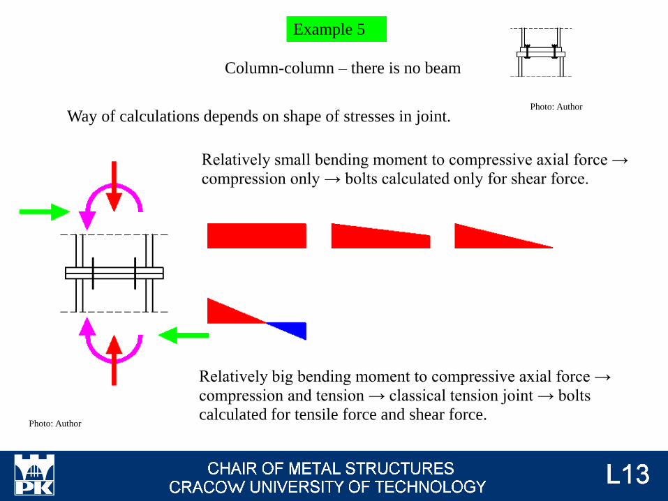
Photo: Author
Way of calculations depends on shape of stresses in joint.
Relatively small bending moment to compressive axial force →
compression only → bolts calculated only for shear force.
Relatively big bending moment to compressive axial force →
compression and tension → classical tension joint → bolts
calculated for tensile force and shear force.
Example 5
Photo: Author
Column-column – there is no beam
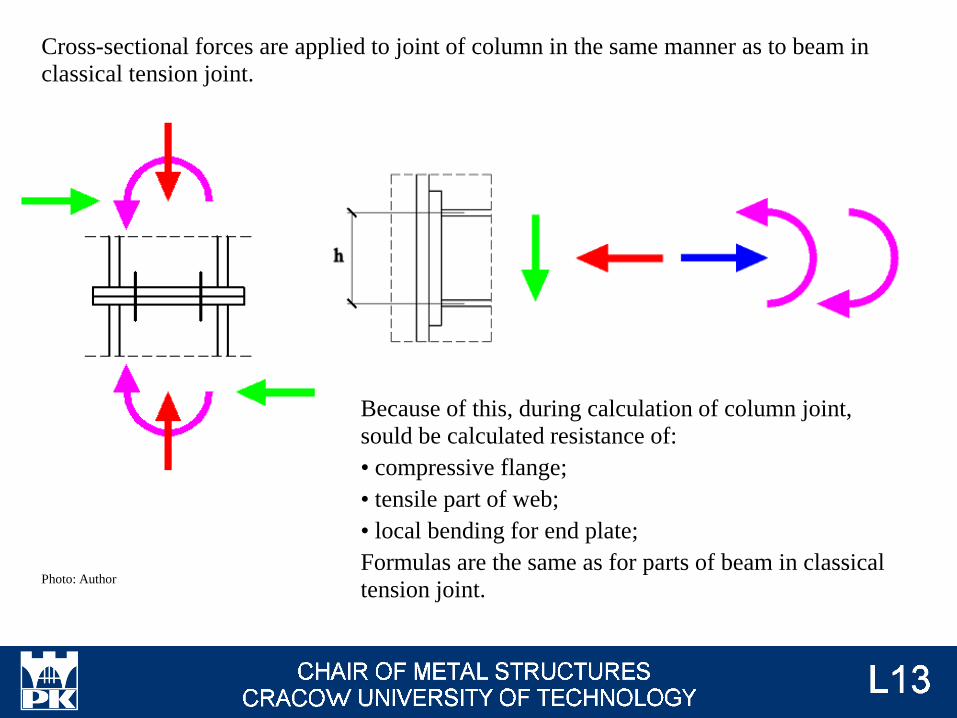
Photo: Author
Cross-sectional forces are applied to joint of column in the same manner as to beam in
classical tension joint.
Because of this, during calculation of column joint,
sould be calculated resistance of:
• compressive flange;
• tensile part of web;
• local bending for end plate;
Formulas are the same as for parts of beam in classical
tension joint.
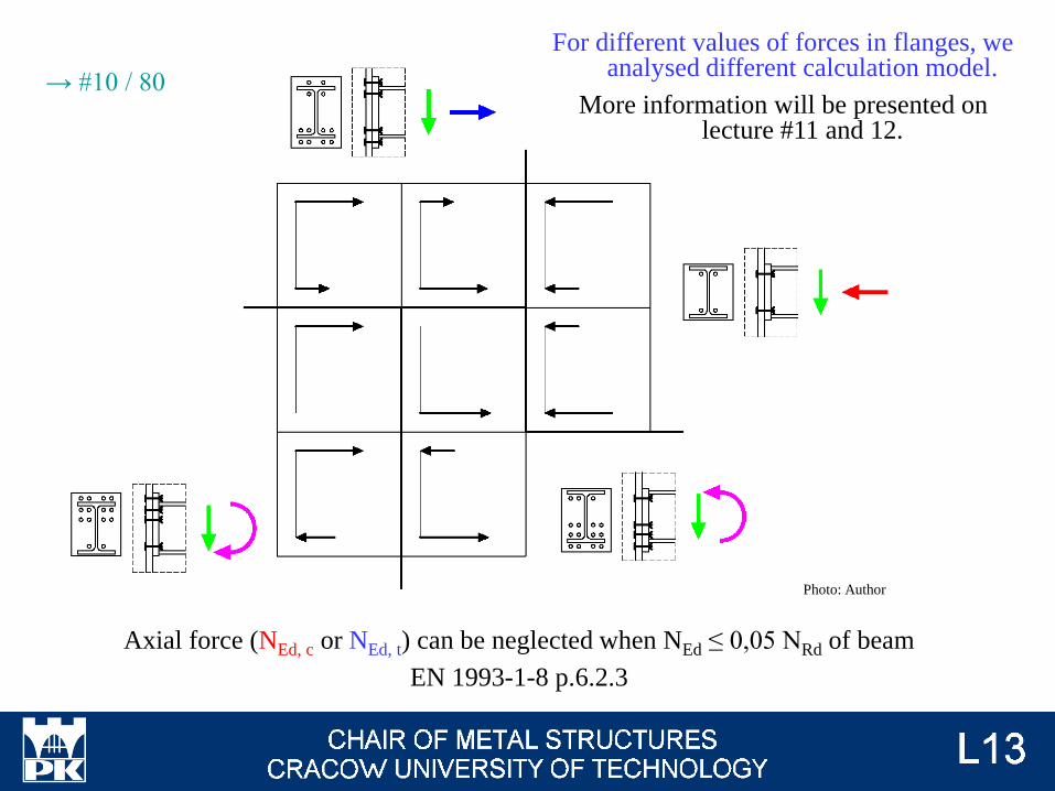
For different values of forces in flanges, we analysed different calculation model.
More information will be presented on lecture #11 and 12.
Axial force (NEd, c or NEd, t) can be neglected when NEd ≤ 0,05 NRd of beam
EN 1993-1-8 p.6.2.3
Photo: Author
→ #10 / 80
There is few inconsequences in Eurocode.
According to EN 1993-1-8 6.2.7.1 (2), we can calculate joints, only when axial force in
beam NEd ≤ 0,05 NRd of beam. If this requirement is not satisfied, we can't calculate
resistances according to formulas, presented in this lecure - but there is no information
in Eurocode, which formulas we can use.
There is information in EN 1993-1-8 6.2.7.1 (2), that if NEd > 0,05 NRd then we
calculate resistance of joint according to formula:
Mj, Ed / Mj, Rd + Nj, Ed / Nj, Rd ≤ 1,0
But there is no clear, what means Nj, Rd and if Mj, Rd is calculated according the same
way as for cause NEd ≤ 0,05 NRd.
Assumptions for case NEd > 0,05 NRd:
First possibility of calculation:
Mj, Rd is calculated according the same formulas as for NEd ≤ 0,05 NRd;
Nj, Rd depends on direction of force:
for compressive force, Nj, Rd = min (column web in compression, beam flange in
compression, column web in shear);
for tensile force, Nj, Rd = [minfirst row of bolt (column web in tension, beam web in
tension, column flange in bending, end plate in bending) + minsecond row of bolt (...) + ... +
minlast row of bolt (...), column web in shear]
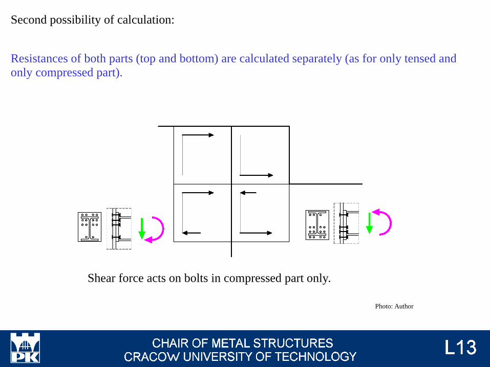
Second possibility of calculation:
Resistances of both parts (top and bottom) are calculated separately (as for only tensed and
only compressed part).
Shear force acts on bolts in compressed part only.
Photo: Author
There is no axial force in bolts, only
shear force acts on bolts.
Photo: Author
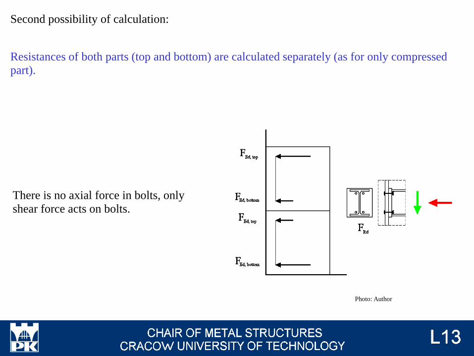
Second possibility of calculation:
Resistances of both parts (top and bottom) are calculated separately (as for only compressed
part).
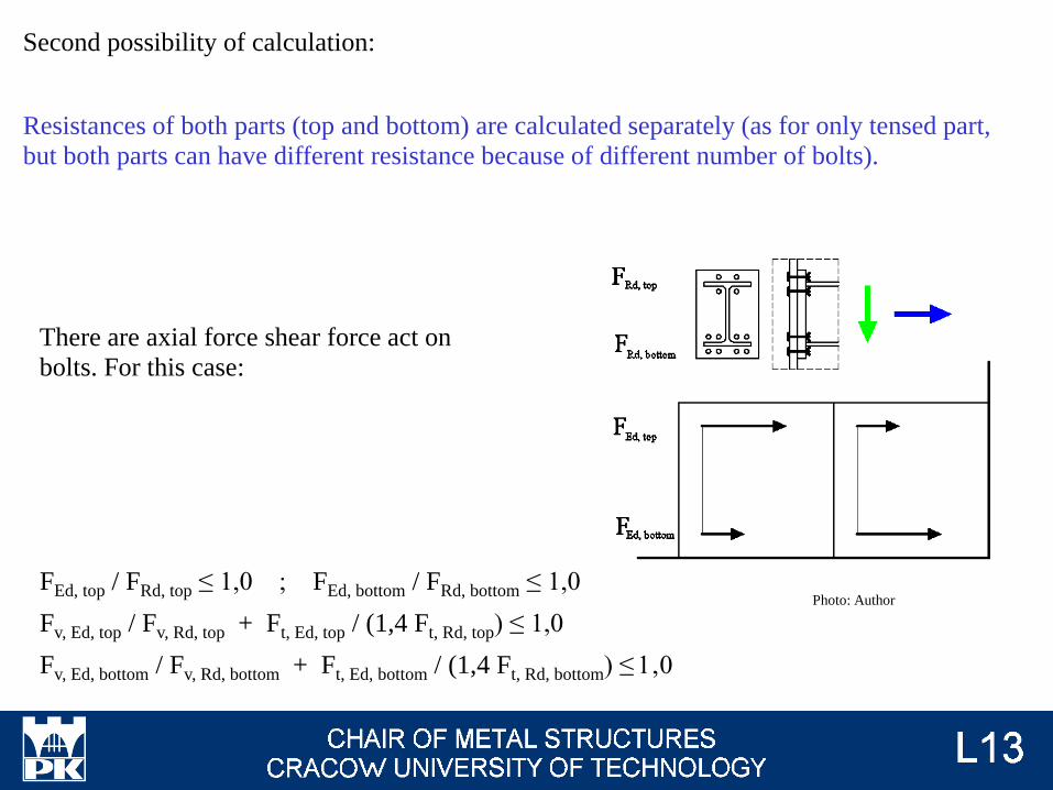
There are axial force shear force act on
bolts. For this case:
FEd, top / FRd, top ≤ 1,0 ; FEd, bottom / FRd, bottom ≤ 1,0
Fv, Ed, top / Fv, Rd, top + Ft, Ed, top / (1,4 Ft, Rd, top) ≤ 1,0
Fv, Ed, bottom / Fv, Rd, bottom + Ft, Ed, bottom / (1,4 Ft, Rd, bottom) ≤ 1,0
Photo: Author
Second possibility of calculation:
Resistances of both parts (top and bottom) are calculated separately (as for only tensed part,
but both parts can have different resistance because of different number of bolts).
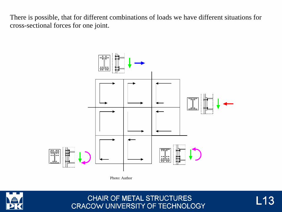
There is possible, that for different combinations of loads we have different situations for
cross-sectional forces for one joint.
Photo: Author
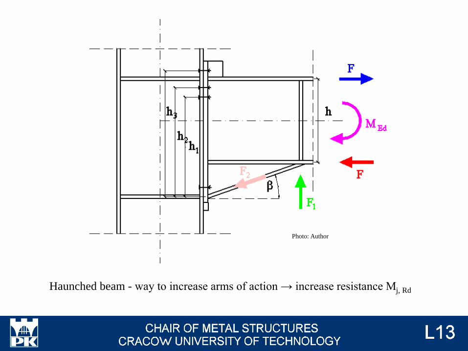
Haunched beam - way to increase arms of action → increase resistance Mj, Rd
Photo: Author

Requirement:
b ≤ 45o
EN 1993-1-8 p.6.2.6.7
There are transverse compression of beam web (F1) and compression of haunched flange (F2):
F = MEd / h
F1 = F tg b
F2 = F / cos b
Calculations of resistance are the same as for transverse compression of web and compression
of flange.
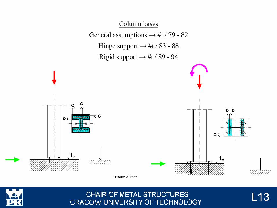
Column bases
General assumptions → #t / 79 - 82
Hinge support → #t / 83 - 88
Rigid support → #t / 89 - 94
Photo: Author
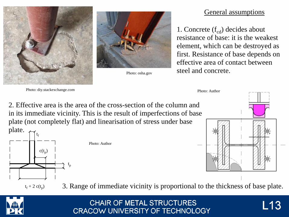
Photo: diy.stackexchange.com
Photo: osha.gov
General assumptions
1. Concrete (fcd) decides about
resistance of base: it is the weakest
element, which can be destroyed as
first. Resistance of base depends on
effective area of contact between
steel and concrete.
2. Effective area is the area of the cross-section of the column and
in its immediate vicinity. This is the result of imperfections of base
plate (not completely flat) and linearisation of stress under base
plate.
Photo: Author
Photo: Author
3. Range of immediate vicinity is proportional to the thickness of base plate.
tp
tf
c(tp)
tf + 2 c(tp)
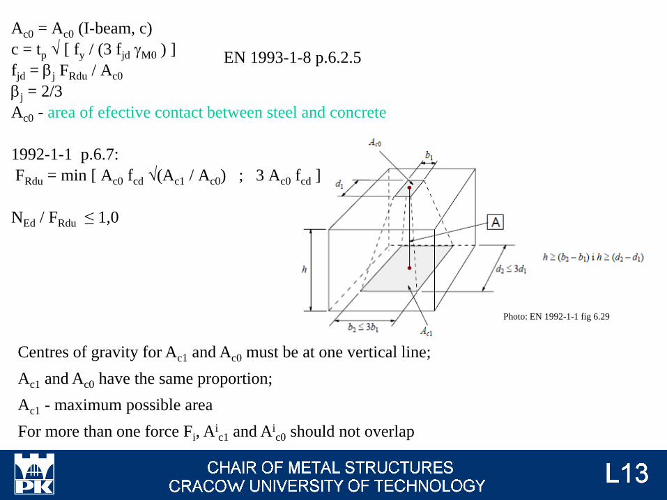
Ac0 = Ac0 (I-beam, c)
c = tp √ [ fy / (3 fjd gM0 ) ]
fjd = bj FRdu / Ac0
bj = 2/3
Ac0 - area of efective contact between steel and concrete
1992-1-1 p.6.7:
FRdu = min [ Ac0 fcd √(Ac1 / Ac0) ; 3 Ac0 fcd ]
NEd / FRdu ≤ 1,0
Centres of gravity for Ac1 and Ac0 must be at one vertical line;
Ac1 and Ac0 have the same proportion;
Ac1 - maximum possible area
For more than one force Fi, Aic1 and Ai
c0 should not overlap
EN 1993-1-8 p.6.2.5
Photo: EN 1992-1-1 fig 6.29
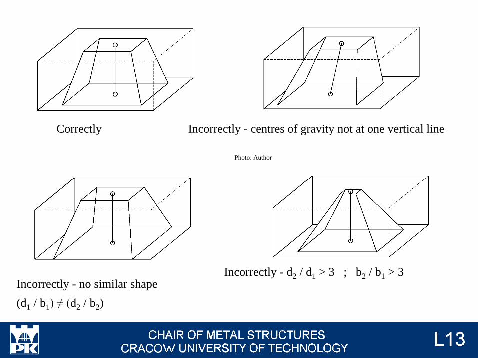
Correctly Incorrectly - centres of gravity not at one vertical line
Photo: Author
Incorrectly - no similar shape
(d1 / b1) ≠ (d2 / b2)
Incorrectly - d2 / d1 > 3 ; b2 / b1 > 3
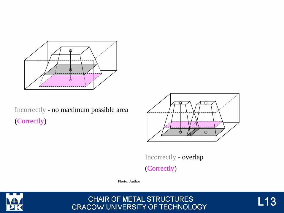
Incorrectly - no maximum possible area
(Correctly)
Incorrectly - overlap
(Correctly)
Photo: Author
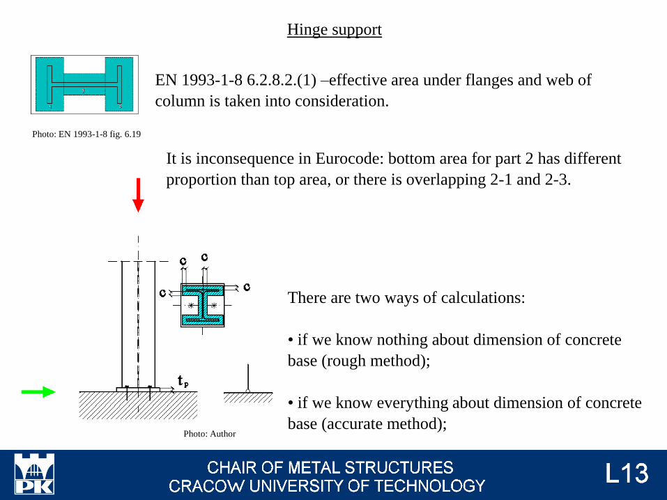
Hinge support
There are two ways of calculations:
• if we know nothing about dimension of concrete
base (rough method);
• if we know everything about dimension of concrete
base (accurate method);Photo: Author
Photo: EN 1993-1-8 fig. 6.19
EN 1993-1-8 6.2.8.2.(1) –effective area under flanges and web of
column is taken into consideration.
It is inconsequence in Eurocode: bottom area for part 2 has different
proportion than top area, or there is overlapping 2-1 and 2-3.
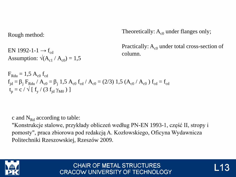
Rough method:
EN 1992-1-1 → fcd
Assumption: √(Ac1 / Ac0) = 1,5
FRdu = 1,5 Ac0 fcd
fjd = bj FRdu / Ac0 = bj 1,5 Ac0 fcd / Ac0 = (2/3) 1,5 (Ac0 / Ac0 ) fcd = fcd
tp = c / √ [ fy / (3 fjd gM0 ) ]
Theoretically: Ac0 under flanges only;
Practically: Ac0 under total cross-section of
column.
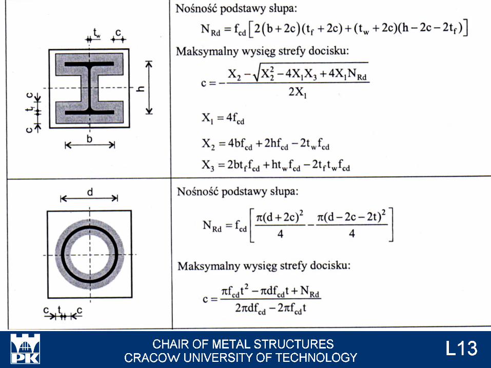
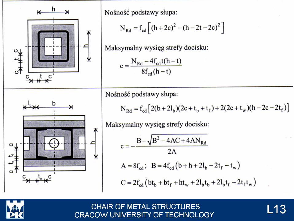
c and NRd according to table:
"Konstrukcje stalowe, przykłady obliczeń według PN-EN 1993-1, część II, stropy i
pomosty", praca zbiorowa pod redakcją A. Kozłowskiego, Oficyna Wydawnicza
Politechniki Rzeszowskiej, Rzeszów 2009.
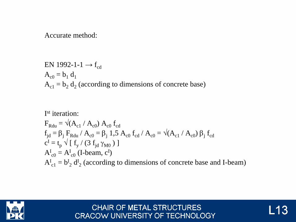
Accurate method:
EN 1992-1-1 → fcd
Ac0 = b1 d1
Ac1 = b2 d2 (according to dimensions of concrete base)
Ist iteration:
FRdu = √(Ac1 / Ac0) Ac0 fcd
fjd = bj FRdu / Ac0 = bj 1,5 Ac0 fcd / Ac0 = √(Ac1 / Ac0) bj fcd
cI = tp √ [ fy / (3 fjd gM0 ) ]
AIc0 = AI
c0 (I-beam, cI)
AIc1 = bI
2 dI2 (according to dimensions of concrete base and I-beam)
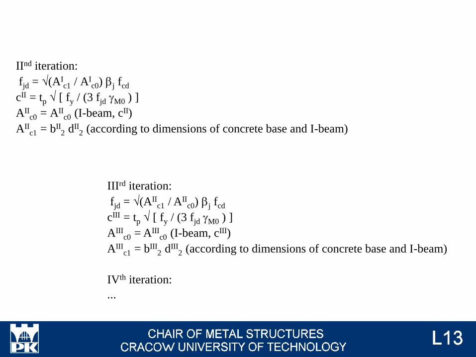
IInd iteration:
fjd = √(AIc1 / AI
c0) bj fcd
cII = tp √ [ fy / (3 fjd gM0 ) ]
AIIc0 = AII
c0 (I-beam, cII)
AIIc1 = bII
2 dII2 (according to dimensions of concrete base and I-beam)
IIIrd iteration:
fjd = √(AIIc1 / AII
c0) bj fcd
cIII = tp √ [ fy / (3 fjd gM0 ) ]
AIIIc0 = AIII
c0 (I-beam, cIII)
AIIIc1 = bIII
2 dIII2 (according to dimensions of concrete base and I-beam)
IVth iteration:
...
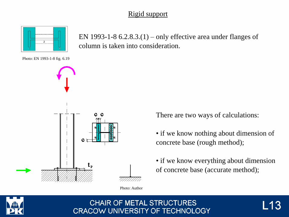
Rigid support
There are two ways of calculations:
• if we know nothing about dimension of
concrete base (rough method);
• if we know everything about dimension
of concrete base (accurate method);
Photo: Author
Photo: EN 1993-1-8 fig. 6.19
EN 1993-1-8 6.2.8.3.(1) – only effective area under flanges of
column is taken into consideration.
Resistance of concret is for both method of calculations the same as for hinge support.
For calculation of resistance rigid support, we need to know:
• resistance of concrete (#t / 79);
• resistance of column web in tension (as beam web in tension, #t / 17);
• resistance of base plate in bending (as end plate in bending, #t / 20);
• resistance of column flange in compression (as beam flange in compression, #t / 5);
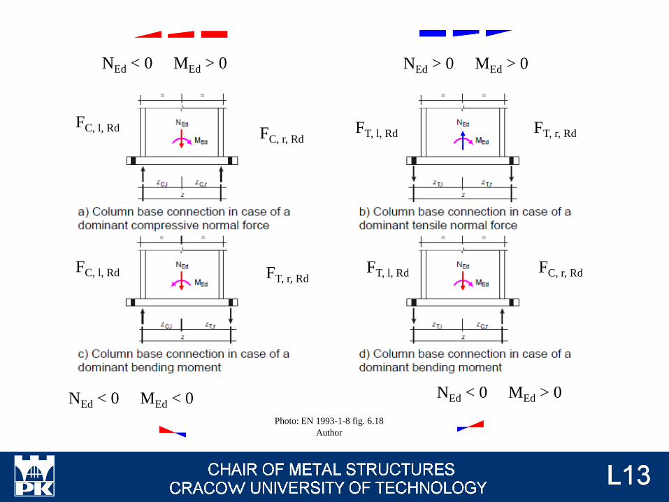
Photo: EN 1993-1-8 fig. 6.18
Author
FT, l, Rd
FT, l, Rd
FC, l, Rd
FC, l, Rd
FC, r, Rd
FC, r, RdFT, r, Rd
FT, r, Rd
NEd < 0 MEd > 0 NEd > 0 MEd > 0
NEd < 0 MEd < 0 NEd < 0 MEd > 0
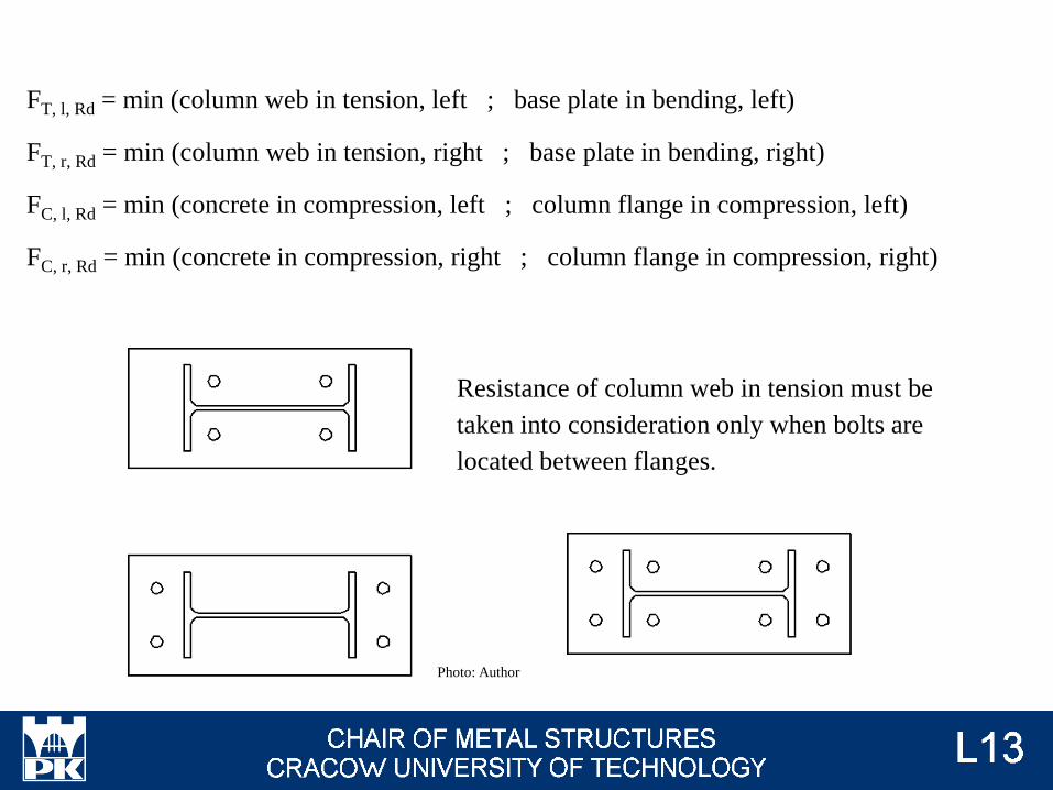
FT, l, Rd = min (column web in tension, left ; base plate in bending, left)
FT, r, Rd = min (column web in tension, right ; base plate in bending, right)
FC, l, Rd = min (concrete in compression, left ; column flange in compression, left)
FC, r, Rd = min (concrete in compression, right ; column flange in compression, right)
Resistance of column web in tension must be
taken into consideration only when bolts are
located between flanges.
Photo: Author
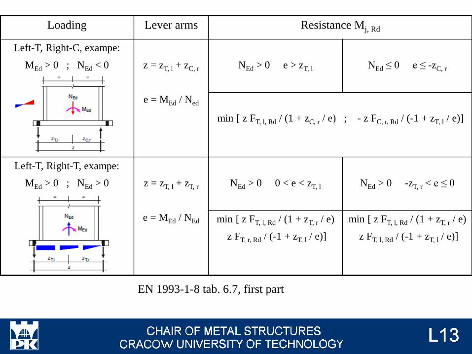
EN 1993-1-8 tab. 6.7, first part
Loading Lever arms Resistance Mj, Rd
Left-T, Right-C, exampe:
MEd > 0 ; NEd < 0 z = zT, l + zC, r
e = MEd / Ned
NEd > 0 e > zT, l NEd ≤ 0 e ≤ -zC, r
min [ z FT, l, Rd / (1 + zC, r / e) ; - z FC, r, Rd / (-1 + zT, l / e)]
Left-T, Right-T, exampe:
MEd > 0 ; NEd > 0 z = zT, l + zT, r
e = MEd / NEd
NEd > 0 0 < e < zT, l NEd > 0 -zT, r < e ≤ 0
min [ z FT, l, Rd / (1 + zT, r / e)
z FT, r, Rd / (-1 + zT, l / e)]
min [ z FT, l, Rd / (1 + zT, r / e)
z FT, l, Rd / (-1 + zT, l / e)]

EN 1993-1-8 tab. 6.7, second part
Loading Lever arms Resistance Mj, Rd
Left-C, Right-T, exampe:
MEd < 0 ; NEd < 0 z = zC, l + zT, r
e = MEd / Ned
NEd > 0 e ≤ -zT, r NEd ≤ 0 e > zC, l
min [ -z FC, l, Rd / (1 + zT, r / e) ; z FT, r, Rd / (-1 + zC, l / e)]
Left-C, Right-C, exampe:
MEd > 0 ; NEd < 0 z = zC, l + zC, r
e = MEd / NEd
NEd ≤ 0 0 < e < zC, l NEd ≤ 0 -zC, r < e ≤ 0
min [ -z FC, l, Rd / (1 + zC, r / e)
-z FC, r, Rd / (-1 + zC, l / e)]
min [ -z FC, l, Rd / (1 + zC, r / e)
-z FC, r, Rd / (-1 + zC, l / e)]
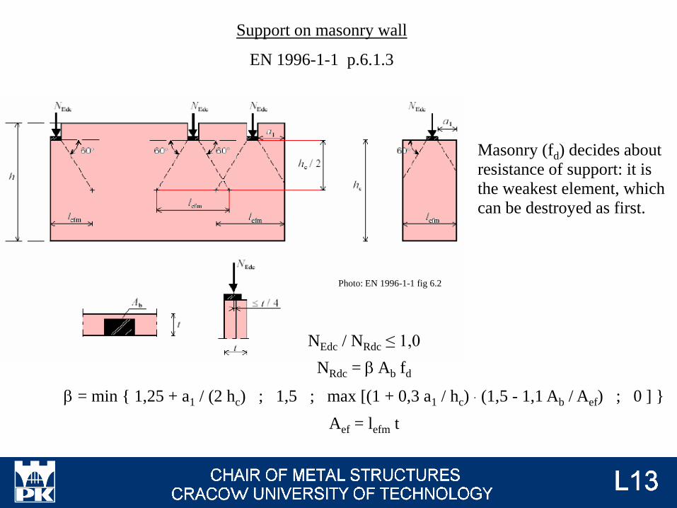
NEdc / NRdc ≤ 1,0
NRdc = b Ab fd
b = min { 1,25 + a1 / (2 hc) ; 1,5 ; max [(1 + 0,3 a1 / hc) ∙ (1,5 - 1,1 Ab / Aef) ; 0 ] }
Aef = lefm t
Support on masonry wall
EN 1996-1-1 p.6.1.3
Photo: EN 1996-1-1 fig 6.2
Masonry (fd) decides about
resistance of support: it is
the weakest element, which
can be destroyed as first.
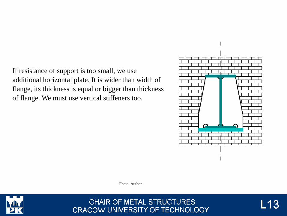
If resistance of support is too small, we use
additional horizontal plate. It is wider than width of
flange, its thickness is equal or bigger than thickness
of flange. We must use vertical stiffeners too.
Photo: Author
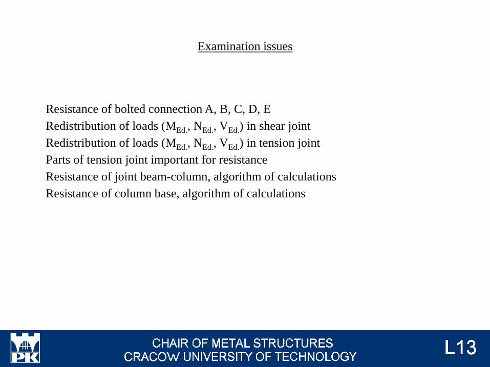
Resistance of bolted connection A, B, C, D, E
Redistribution of loads (MEd., NEd., VEd.) in shear joint
Redistribution of loads (MEd., NEd., VEd.) in tension joint
Parts of tension joint important for resistance
Resistance of joint beam-column, algorithm of calculations
Resistance of column base, algorithm of calculations
Examination issues
Base - fundament
Flange cleat - nakładka z kątownika
End-plate - blacha czołowa
Base plate - blacha stopowa
Double-side joint - węzeł dwustronny