Load Protection Surge Arrester - iemmyanmar.com€¦ · 8 9 Rated discharge current (Imax) /...
15
Electrical distribution Load Protection Surge Arrester LV product characteristics
-
Upload
nguyenthuy -
Category
Documents
-
view
234 -
download
0
Transcript of Load Protection Surge Arrester - iemmyanmar.com€¦ · 8 9 Rated discharge current (Imax) /...

Electrical distribution
Load ProtectionSurge Arrester
LV product characteristics

1
General contents
iPRF1 12.5r/PRF1 Master/PRD1 25r/PRD1 Master 2-6
iPRD surge arresters 8-11
iPF surge arresters 12-15
iPRC, iPRI surge arresters 16-17
iPRD-DC surge arresters 18-20
Photovoltaic 21-25

iPRF1 12.5r (1P+N, 3P+N) PRF1 Master (1P) iPRF1 12.5r (3P) PRF1 Master (2P, 3P, 4P)
Type Product solution Neutral point connection
Recommended accessory
Fixed surge arrester
1P+N 3P+N 1P 2P 3P 4P
iPRF1 12.5rT1, T2
A9L16632 A9L16634 TT, TN-S
A9L16633 TN-C, IT 230 V
PRF1 MasterT1
2 x 16630 IT (1) distributed neutral 1664316630 3 x 16630 IT (1) non-distributed
neutral16644
4 x 16630 IT (1) distributed neutral 16645
PRD1 25r (1P+N, 3P+N) PRD1 Master (1P+N, 3P+N) PRD1 25r (1P) PRD1 25r (2P, 3P, 4P) PRD1 Master (2P, 3P, 4P)
Cartridge surge arrester
1P+N 3P+N 1P 2P 3P 4P
PRD1 25rT1 + T2
16330 16332 TT, TN-S
2 x 16329 4 x 16329 IT 230 V
16329 16331 TN-C, IT 230 V
PRD1 MasterT1
16361 16363 TT, TN-S
16360 2 x 16360 16362 4 x 16360 TN-C, IT 230 V
(1) Version without indicator light.
Protection Load protection
iPRF1 12.5r/PRF1 Master/PRD1 25r/PRD1 MasterType 1 and 2 LV surge arresters
Protection Load protection
iPRF1 12.5r/PRF1 Master/PRD1 25r/PRD1 MasterType 1 and 2 LV surge arresters (cont.)
iPRF1 12.5r/PRF1 Master/PRD1 25r/PRD1 MasterThe Type 1 surge arrester is recommended for electrical installations in the service sector and industrial buildings protected by a lightning conductor or by a meshed cage.It protects electrical installations against direct lightning strikes.It is used to conduct the direct lightning current, propagating from the earth conductor to the network conductors.It must be installed with an upstream disconnection device, such as a fuse or circuit-breaker, whose breaking capacity must be at least equal to the maximum prospective short-circuit current at the installation point.iPRF1 12.5r and PRD1 25r surge arresters also provide Type 2 protection and protect the electrical installation by finely clipping the lightning wave overvoltages.
DB
1190
38
DB
1189
11
DB
1190
39
The Type 1 range of surge arresters meets the normative withstand capability of current wave type 10/350 μs (8/20 μs for Type 2 surge arresters). It is suitable for use with TT, TN-S, TN-C and 230 V IT earthing connection systems (neutral point connection). In addition, the PRF1 Master surge arrester covers the 400 V IT system. iPRF1 12.5r and PRD1 surge arresters are fitted with a remote transfer contact to send "end-of-life indication" information.PRD1 surge arresters are fitted with easy-to-replace withdrawable cartridges.
DB
1190
36
DB
1225
27
DB
1225
28
DB
1190
37iPRF1 12.5r
PB
1042
60-3
5
PRD1 25r
PB
1042
64-3
5
PRD1 Master
DB
1233
84
DB
1225
27
PB
1042
75-3
5
iPRF1 12.5r
2 3

4 5
Protection Load protection
iPRF1 12.5r/PRF1 Master/PRD1 25r/PRD1 MasterType 1 and 2 LV surge arresters (cont.)
Type Nb. of poles
Width I imp (kA) (10/350)Impulse current
I max (kA) (8/20)Maximal discharge current
In - kARated discharge current
Up - kVDegree of protection
Un - VNominal line voltage
Uc - VMaximum steady state voltage
Fixed surge arrester
9 mm modules
Surge arrester
Surge arrester + disconnector
iPRF1 12.5r Type 1 + 2
1P+N 4 12.5/50 N/PE 50 25 1.5 230 350 A9L166323P 8 12.5 50 25 1.5 230 / 400 350 A9L166333P+N 8 12.5/50 N/PE 50 25 1.5 230 / 400 350 A9L16634
PRF1 Master Type 1
1P 4 50 35 - 50 1.5 230 440 16630Withdrawable surge arresterPRD1 25r Type 1 + 2
1P 4 25 40 25 1.5 230 350 163291P+N 8 25/100 N/PE 40 25 1.5 230/400 350 163303P 12 25 40 25 1.5 230 350 163313P+N 16 25/100 N/PE 40 25 1.5 230/400 350 16332
PRD1 Master Type 1
1P 4 25 - 25 1.5 230 350 163601P+N 8 25/100 N/PE - 25 1.5 230/400 350 163613P 12 25 - 25 1.5 230 350 163623P+N 16 25/100 N/PE - 25 1.5 230/400 350 16363
Spare cartridge C1 Master-350 - 4 - - - 25 1.5 - 350 16314C1 25-350 - 23 mm - - - 25 1.5 - 350 16315C2 40-350 - 12 mm - - - 20 1.4 - 350 16316C1 Neutral-350 - 4 - - - - - - 350 16317
Technical dataiPRF1 12.5r PRF1 Master PRD1 25r PRD1 Master
Operating frequency 50 Hz 50/60 Hz 50 Hz 50 HzDegree of protection Front panel IP40 IP40 IP40 IP40
Terminals IP20 IP20 IP20 IP20Impacts IK05 IK05 IK05 IK05
Response time y 25 ns y 1 ms y 25 ns y 100 nsEnd-of-life indication Green: correct operation - White: correct operation White: correct operation
Red: at end of life - Red: at end of life Red: at end of life Remote notification
1.5 A/250 V AC - 1 A/250 V AC.0.2 A/125 V DC
1 A/250 V AC.0.2 A/125 V DC
By tunnel terminal Rigid cable 10...35 mm² 10...50 mm² 2.5...35 mm² 10...35 mm²Flexible cable
10...25 mm² 10...35 mm² 2.5...25 mm² 10...25 mm²
Operating temperature -25°C to +60°C -40°C to +85°C -25°C to +60°C -25°C to +60°CStandards Type 1 IEC 61643-1 T1.
EN 61643-11 Type 1IEC 61643-1 T1. EN 61643-11 Type 1
IEC 61643-1 T1. EN 61643-11 Type 1
IEC 61643-1 T1. EN 61643-11 Type 1
Type 2 IEC 61643-1 T2. EN 61643-11 Type 2
- IEC 61643-1 T2. EN 61643-11 Type 2
-
Certification CE KEMAKEUR, CE KEMAKEUR, CE CE
Surge arresters Spare cartridgePhase NeutralType 1 Type 2
PRD1 25rPRD1 25r 1P 16315 16316 -PRD1 25r 1P+N 16315 16316 16317PRD1 25r 3P 3 x 16315 3 x 16316 -PRD1 25r 3P+N 3 x 16315 3 x 16316 16317PRD1 Master
PRD1 Master 1P 16314 - -PRD1 Master 1P+N 16314 - 16317PRD1 Master 3P 3 x 16314 - -PRD1 Master 3P+N 3 x 16314 - 16317
Protection Load protection
iPRF1 12.5r/PRF1 Master/PRD1 25r/PRD1 MasterType 1 and 2 LV surge arresters (cont.)
AccessoriesType Number of poles
4P Wiring comb busbars 4 166436P Wiring comb busbars 6 16644Peignes de câblage 8P 8 16645200 mm flexible cable (PRF1 Master) 16646
Choice of disconnector / surge arresterType Iimp
:impulse current
Isc: prospective short-circuit current at the installation point
10 kA 15 kA 25 kA 36 kA 50 kA
iPRF1 12.5r 12.5 kA C120N 80 A curve C C120H 80 A curve C orNG125N 80 A curve C
NG125N 80 A curve C NG125H 80 A curve C NG125L 80 A curve C
PRF1 Master 35 kA Compact NSX160B 160 A TM Compact NSX160F 160 A
Compact NSX160N 160 A
PRD1 25r 25 kA NG125N 80 A curve C -PRD1 Master 25 kA NG125N 80 A curve C NG125H 80 A curve C NG125L 80 A curve C
DB
1233
70

6 7
Dimensions (mm)36 7 3044
74
46.5 151.5
DB
1239
28
PRF1 Master iPRF1 12.5r
PRD1 Master
PRD1 25r
DB
1239
27D
B12
3929
DB
1239
30Protection Load protection
iPRF1 12.5r/PRF1 Master/PRD1 25r/PRD1 MasterType 1 and 2 LV surge arresters (cont.)

8 9
Rated discharge current (Imax) / Nominal discharge current (In)
Type of protection
Network Earthing system
Transfer Surge arrester name
Width in mod. of 9 mm
Up - (kV) Voltage protection level
Un - (V) Rated voltage network
Uc - (V) Maximum continuous operating voltage
CM* DM* CM* DM*
Incoming Secondary 1P+N 3P+N 1P 2P 3P 4P L/t N/t L/N L/t N/t L/N65 kA / 20 kA iPRD65
Very high risk level (strongly exposed site)
iPRD65 A9L16555 IT b iPRD65r 1P IT 2 y 2 - - 230 460 - - A9L16556 TT & TN b iPRD65r 1P y 1.5 - - - 340 - -
A9L16557 TT & TN-S b iPRD65r 1P+N 4 - y 1.5 y 1.5 - - 260 340 A9L16442 TN-C b iPRD65r 2P y 1.5 y 1.5 - - 340 340 -
A9L16558 IT b iPRD65r 3P IT 6 y 2 - - 230/400 460 - - A9L16443 TN-C b iPRD65r 3P y 1.5 - - - 340 - -
A9L16559 TT & TN-S b iPRD65r 3P+N 8 - y 1.5 y 1.5 - - 260 340 A9L16659 TN-C b iPRD65r 4P y 1.5 y 1.5 - - 340 340 -
40 kA / 15 kA iPRD40High risk level iPRD40 A9L16561 TT & TN b iPRD40r 1P 2 y 1.4 - - 230 340 - -
A9L16566 TT & TN iPRD40 1P y 1.4 - - - 340 - -A9L16562 TT & TN-S b iPRD40r 1P+N 4 - y 1.4 y 1.4 - - 260 340A9L16567 TT & TN-S iPRD40 1P+N - y 1.4 y 1.4 - - 260 340
A9L16444 TN-C b iPRD40r 2P y 1.4 y 1.4 - - 340 340 - A9L16667 TN-C iPRD40 2P y 1.4 y 1.4 - - 340 340 - A9L16445 TN-C b iPRD40r 3P 6 y 1.4 - - 230/400 340 - - A9L16568 TN-C iPRD40 3P y 1.4 - - - 340 - - A9L16563 IT b iPRD40r 3P IT y 2 - - - 460 - - A9L16564 TT & TN-S b iPRD40r 3P+N 8 - y 1.4 y 1.4 - - 260 340 A9L16569 TT & TN-S iPRD40 3P+N - y 1.4 y 1.4 - - 260 340 A9L16597 IT b iPRD40r 4P IT y 2 y 2 - - 460 460 - A9L16664 TN-C b iPRD40r 4P y 1.4 y 1.4 - - 340 340 -
A9L16669 TN-C iPRD40 4P y 1.4 y 1.4 - - 340 340 -20 kA / 5 kA iPRD20
Medium risk level iPRD20 A9L16571 TT & TN iPRD20 1P 2 y 1.1 - - 230 340 - -A9L16672 TT & TN-S b iPRD20r 1P+N 4 - y 1.4 y 1.1 - - 260 340A9L16572 TT & TN-S iPRD20 1P+N - y 1.4 y 1.1 - - 260 340
A9L16446 TN-C iPRD20 2P y 1.1 y 1.1 - - 340 340 - A9L16447 TN-C iPRD20 3P 6 y 1.1 - - 230/400 340 - - A9L16573 IT b iPRD20r 3P IT y 1.6 - - - 460 - -
A9L16674 TT & TN-S b iPRD20r 3P+N 8 - y 1.4 y 1.1 - - 260 340A9L16574 TT & TN-S iPRD20 3P+N - y 1.4 y 1.1 - - 260 340
A9L16599 IT b iPRD20r 4P IT y 1.6 y 1.6 - - 460 460 -A9L16673 TN-C iPRD20 4P y 1.1 y 1.1 - - 340 340 -
8 kA / 2.5 kA iPRD8 (1) Type 2 / Type 3Secondary protection: placed near the loads to be protected when they are at a distance of more than 30 m from the incoming surge arrester
iPRD8 A9L16576 TT & TN iPRD8 1P 2 y 1 / y 1 - - 230 340 - -A9L16677 TT & TN-S b iPRD8r 1P+N 4 - y 1.4 / y 1 y 1 / y 1.1 - - 260 340A9L16577 TT & TN-S iPRD8 1P+N - y 1.4 / y 1 y 1 / y 1.1 - - 260 340
A9L16448 TN-C iPRD8 2P y 1 / y 1 y 1 / y 1 - - 340 340 - A9L16449 TN-C iPRD8 3P 6 y 1 / y 1 - - 230/400 340 - - A9L16578 IT b iPRD8r 3P IT y 1.4 / y 1.6 - - - 460 - -
A9L16679 TT & TN-S b iPRD8r 3P+N 8 - y 1.4 / y 1 y 1 / y 1.1 - - 260 340A9L16579 TT & TN-S iPRD8 3P+N - y 1.4 / y 1 y 1 / y 1.1 - - 260 340
A9L16678 IT b iPRD8r 4P IT y 1.4 / y 1.6 y 1.4 / y 1.6 - - 460 460 - A9L16680 TN-C iPRD8 4P y 1 / y 1 y 1 / y 1 - - 340 340 -
* CM: common mode (phase to earth and neutral to earth). * DM: differential mode (phase to neutral). (1) Uoc: combinated waveform voltage: 10 kV.
Surge arrester/circuit breaker associationType of surge arrester Associated circuit breaker
iPRD65 Curve C 50 AiPRD40 Curve C 40 AiPRD20 Curve C 25 AiPRD8 Curve C 20 A
Spare cartridgesType Spare cartridges for Cat. no
C 65-460 iPRD65r IT A9L16682C 65-340 iPRD65r A9L16681C 40-460 iPRD40r IT A9L16684C 40-340 iPRD40, iPRD40r A9L16685C 20-460 iPRD20r IT A9L16686C 20-340 iPRD20, iPRD20r A9L16687C 8-460 iPRD8r IT A9L16688C 8-340 iPRD8, iPRD8r A9L16689C neutral All products A9L16691
ProtectionLoad protection
iPRD surge arrestersType 2 or 3 LV withdrawable surge arresters
ProtectionLoad protection
iPRD surge arrestersType 2 or 3 LV withdrawable surge arresters (cont.)
iPRD withdrawable surge arresters allow quick replacement of damaged cartridges.
3P
PB
1052
75-3
5
DB
1229
42
DB
1229
43
3P+N
PB
1052
76-3
5
Cartridge
PB
1052
72-3
5
1P+N
PB
1052
74-3
5

10 11
Connection
DB
1231
30 Type Tightening torque Copper cablesRigid Flexible or ferrule
iPRD 2 N.m 2.5 to 25 mm2 2.5 to 16 mm2
6.5 mm14 mm
PZ2 DB
1229
45
DB
1229
46
Weight (g)Surge arresterType iPRD
1P 1152P 2203P 3404P 450
ProtectionLoad protection
iPRD surge arrestersType 2 or 3 LV withdrawable surge arresters (cont.)
Technical dataMain characteristics
Operating frequency 50/60 HzOperating voltage (Ue) 230/400 V ACPermanent operating current (Ic) < 1 mAResponse time < 25 nsEnd of life indication: by mechanical indicator
White In operationRed At end of life
End of life remote indication By contact NO, NC 250 V / 0.25 AAdditional characteristics
Operating temperature -25°C to +60°C
Type of connection terminals Tunnel terminals, 2.5 to 35 mm²
Standards IEC 61643-1 T2 and EN 61643-11 Type 2
ProtectionLoad protection
iPRD surge arrestersType 2 or 3 LV withdrawable surge arresters (cont.)
Dimensions (mm)
DB
1235
96
1P 1P+N 2P
3P 3P+N 4P

12 13
Each surge arrester in the range has a specific application: b incoming protection (type 2): v the iPF65(r) is recommended for a very high risk level (strongly exposed site) v the iPF40(r) is recommended for a high risk level v the iPF20 is recommended for a medium risk level b secondary protection (type 2 or 3): v the iPF8 ensures secondary protection of loads to be protected and is placed in
cascade with the incoming surge arresters. This surge arrester is required when the loads to be protected are at a distance of more than 30 m from the incoming surge arrester.
The iPF surge arresters with “r” indication have remote transfer of the information: “surge arrester to be replaced”.
The iPF multi-pole single-piece surge arrester range is adapted for earthing systems: TT, TN-S, TN-C. Type 2 surge arresters are tested with a 8/20 ms current wave. Type 3 surge arresters are tested with a 12/50 ms and 8/20 ms combined wave.
1P+N.
3P+N.
PB
1052
78-3
5P
B10
5280
-35
ProtectionLoad protection
iPF surge arrestersType 2 or 3 LV surge arresters
ProtectionLoad protection
iPF surge arrestersType 2 or 3 LV surge arresters (cont.)
Rated discharge current (Imax) / Nominal discharge current (In)
Type of protection Network Earthing system
Transfer Surge arrester name
Width in mod. of 9 mm
Up - (kV) Voltage protection level
Un - (V) Rated voltage network
Uc - (V) Maximum continuous operating voltage
CM* DM* CM* DM*
Incoming Secondary (type 2 or 3)
1P+N 3P+N 1P 2P 3P 4P L/t N/t L/N L/t N/t L/N
65 kA / 20 kA iPF65iPF65 A9L15683 TT & TN iPF65 1P 2 y 1.5 - - 230 340 - -
A9L15684 TT & TN-S iPF65 1P+N 4 - y 1.5 y 1.5 - 260 340 A9L15584 TN-C iPF65 2P y 1.5 y 1.5 - 340 340 -
A9L15581 TN-C iPF65 3P 8 y 1.5 - - 230/400 340 - - A9L15685 TT & TN-S b iPF65r 3P+N - y 1.5 y 1.5 - 260 340
A9L15586 TT & TN-S iPF65 3P+N - y 1.5 y 1.5 - 260 340 A9L15585 TN-C b iPF65r 4P y 1.5 y 1.5 - 340 340 -
40 kA / 15 kA iPF40High risk level iPF40 A9L15686 TT & TN iPF40 1P 2 y 1.5 - - 230 340 - -
A9L15687 TT & TN-S iPF40 1P+N 4 - y 1.5 y 1.5 - 260 340 A9L15587 TN-C iPF40 2P y 1.5 y 1.5 - 340 340 - A9L15582 TN-C iPF40 3P 8 y 1.5 - - 230/400 340 - - A9L15690 TT & TN-S b iPF40r 3P+N - y 1.5 y 1.5 - 260 340 A9L15688 TT & TN-S iPF40 3P+N - y 1.5 y 1.5 - 260 340 A9L15590 TN-C b iPF40r 4P y 1.5 y 1.5 - 340 340 - A9L15588 TN-C iPF40 4P y 1.5 y 1.5 - 340 340 -
20 kA / 5 kA iPF20Medium risk level iPF20 A9L15691 TT & TN iPF20 1P 2 y 1.1 - - 230 340 - -
A9L15692 TT & TN-S iPF20 1P+N 4 - y 1.5 y 1.1 - 260 340 A9L15592 TN-C iPF20 2P y 1.1 y 1.1 - 340 340 - A9L15597 TN-C iPF20 3P 8 y 1.1 - - 230/400 340 - -
A9L15693 TT & TN-S iPF20 3P+N - y 1.5 y 1.1 - 260 340A9L15593 TN-C iPF20 4P y 1.1 y 1.1 - 340 340 -
8 kA / 2.5 kA iPF8 (1) Type 2 / Type 3Secondary protection: placed near the loads to be protected when they are at a distance of more than 30 m from the incoming surge arrester
iPF8 A9L15694 TT & TN iPF8 1P 2 y 1 / y 1.1 - - 230 340 - -A9L15695 TT & TN-S iPF8 1P+N 4 - y 1.5 / y 1.2 y 1 / y 1.1 - 260 340
A9L15595 TN-C iPF8 2P y 1 / y 1.1 y 1 / y 1.1 - 340 340 - A9L15598 TN-C iPF8 3P 8 y 1 / y 1.1 - - 230/400 340 - -
A9L15696 TT & TN-S iPF8 3P+N - y 1.5 / y 1.2 y 1 / y 1.1 - 260 340 A9L15596 TN-C iPF8 4P y 1 / y 1.1 y 1 / y 1.1 - 340 340 -
* CM: common mode (phase to earth and neutral to earth). * DM: differential mode (phase to neutral). (1) Uoc: combinated waveform voltage: 10 kV.
DB
1229
42
DB
1229
43
Surge arrester/circuit breaker associationType of surge arrester Associated circuit breaker
iPF65 Curve C 50 AiPF40 Curve C 40 AiPF20 Curve C 25 AiPF8 Curve C 20 A

14 15
ProtectionLoad protection
iPF surge arrestersType 2 or 3 LV surge arresters (cont.)
ProtectionLoad protection
iPF surge arrestersType 2 or 3 LV surge arresters (cont.)
Dimensions (mm)
DB
1235
95
1P 1P+N
2P3P3P+N4P
Weight (g)Surge arresterType iPF
1P 1252P 2103P 3354P 420
Connection
DB
1231
29 Type Tightening torque
Copper cablesRigid Flexible or ferrule
iPF8 / 20 Ph / N 1.2 N.m 16 mm2 max. 10 mm2 max.t 2 N.m 25 mm2 max. 16 mm2 max.
DB
1231
29 iPF40 / 65 Ph / N 2 N.m 25 mm2 max. 16 mm2 max.t 3.5 N.m 50 mm2 max. 35 mm2 max.
6.5 mm11 mm
PZ2
DB
1229
45
DB
1229
46
6.5 mm16 mm
PZ2
Technical dataMain characteristics
Operating frequency 50/60 HzOperating voltage (Ue) 230/400 V ACPermanent operating current (Ic) < 1 mAResponse time < 25 nsEnd of life indication: by green/red mechanical indicator
Green In operationRed At end of life
End of life remote indication By contact NO, NC 250 V / 0.25 AAdditional characteristics
Operating temperature -25°C to +60°C
Type of connection terminals Tunnel terminals, 2.5 to 35 mm²
Standards IEC 61643-1 T2 and EN 61643-11 Type 2

16 17
ProtectionLoad protection
iPRC, iPRI surge arresters
Analogue telephone line protection: the iPRC surge arrester wired in series to the private installation input protects the telephones, the PABX, the modems (including ADSL), etc.
Protection for 2 low-current lines without common potential or 4 lines with common reference potential: the iPRI protects the measuring instrument and PLC "sensor" inputs and the DC power supply inputs up to 53 V and AC power supply inputs up to 37 V. The input current must not exceed 300 mA.
3
L'1 L1 L'2 L2
L'1 L1 L'2 L2
410
3
Line L1 Cables 7-8 Line L1 Cables 5-6Line L2 Cables 11-12 Line L2 Cables 11-12– – Line L’1 Cables 1-2– – Line L’2 Cables 7-8t Cable 3 t Cables 3-4-9-10IN Ligne side IN Ligne side
Catalogue numbers OUT Protected side OUT Protected side
Surge arresters iPRC iPRIMains voltage (Un) <130 V AC 48 V DC
Analogue telephone system b –Telephone transmitter b –Digital telephone system – b Automation network – b VLV load power supply (12…48 V) – b xDSL compatibility b –Cat. no.. A9L16337 A9L16339Width in 9 mm modules 2 2
DB
1265
23
DB
1225
85
Technical dataMain characteristics
iPRC iPRI
Number of protected lines 2 2Test category IEC/VDE C1, C2, C3, D1, B2 C1, C2, C3, D1, B2Maximum continuous voltage (Uc) 180 V DC, 130 V AC 53 V DC, 37 V ACLimitation voltage (Up) 300 V 70 VRated discharge current (8/20) (In) 10 kA 10 kAMaximum discharge current (8/20) (Imax) 18 kA 10 kAResponse time < 500 ns y 1 nsNominal impulse current 100 A 70 ARated current (IN) 450 mA (up to 45°C) 300 mA (up to 45°C)Series resistor 2.2 Ω 4.7 ΩEnd-of-life information by Loss of dialling tone Loss of transmission
Additional characteristicsDegree of protection Device only IP20 IP20
Device in modular enclosure
IP40 IP40
IK 05 05Operating temperature -25°C to +60°C -25°C to +60°CStorage temperature -40°C to +85°C -40°C to +85°C
A9L16337
PB
1042
69-3
5
A9L16339
PB
1042
70-3
5
Dimensions (mm)
DB
1225
85
18 52
66
90 45
ProtectionLoad protection
iPRC, iPRI surge arresters (cont.)
Protection against overvoltages related to lightning strikes.
DB
1226
00
3iPRC
iPRI
iPRI
Position switches
Analog sensors
Db1
2262
4
DB
1166
19
Country approval pictograms
DiagramsWeight (g)Surge arrestersType iPRC iPRI
25 65
Connection
DB
1225
84 Tightening torque
Copper cablesRigid Flexible or ferrule
0.8 N.m 0.2 to 4 mm2 0.2 to 2,5 mm2
DB
1229
45
DB
1229
46
3 mm
8 mm
IP20 IK05
IP40 IK05
PZ1
DB
1233
09D
B12
3300
Clip on DIN rail 35 mm.
± 30° vertical.
DB
1233
11
18 19
PB
1075
85-4
0
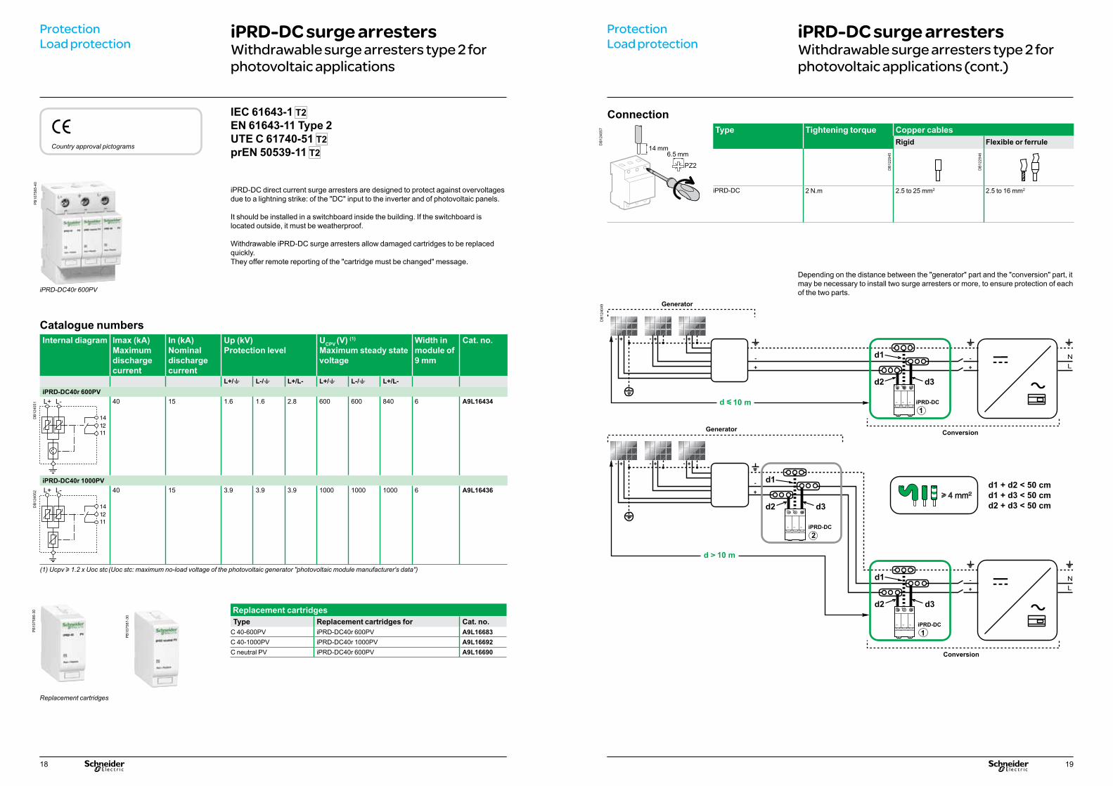
10 m iPRD-DC 1
10 m
iPRD-DC 1
iPRD-DC 2
ProtectionLoad protection
iPRD-DC surge arrestersWithdrawable surge arresters type 2 for photovoltaic applications
Catalogue numbersInternal diagram Imax (kA)
Maximum discharge current
In (kA)Nominal discharge current
Up (kV)Protection level
UCPV (V) (1)
Maximum steady state voltage
Width in module of 9 mm
Cat. no.
L+/t L-/t L+/L- L+/t L-/t L+/L-iPRD-DC40r 600PV
DB
1240
51 40 15 1.6 1.6 2.8 600 600 840 6 A9L16434
iPRD-DC40r 1000PV
DB
1240
52 40 15 3.9 3.9 3.9 1000 1000 1000 6 A9L16436
(1) Ucpv u 1.2 x Uoc stc (Uoc stc: maximum no-load voltage of the photovoltaic generator "photovoltaic module manufacturer's data")
iPRD-DC direct current surge arresters are designed to protect against overvoltages due to a lightning strike: of the "DC" input to the inverter and of photovoltaic panels.
It should be installed in a switchboard inside the building. If the switchboard is located outside, it must be weatherproof.
Withdrawable iPRD-DC surge arresters allow damaged cartridges to be replaced quickly.They offer remote reporting of the "cartridge must be changed" message.
Replacement cartridgesType Replacement cartridges for Cat. no.
C 40-600PV iPRD-DC40r 600PV A9L16683C 40-1000PV iPRD-DC40r 1000PV A9L16692C neutral PV iPRD-DC40r 600PV A9L16690
Generator
ConversionGenerator
Conversion
eCountry approval pictograms
IEC 61643-1 T2 EN 61643-11 Type 2 UTE C 61740-51 T2 prEN 50539-11 T2
ProtectionLoad protection
iPRD-DC surge arrestersWithdrawable surge arresters type 2 for photovoltaic applications (cont.)
Depending on the distance between the "generator" part and the "conversion" part, it may be necessary to install two surge arresters or more, to ensure protection of each of the two parts.
Connection
DB
1240
57 Type Tightening torque Copper cablesRigid Flexible or ferrule
iPRD-DC 2 N.m 2.5 to 25 mm2 2.5 to 16 mm2
6.5 mm14 mm
PZ2
DB
1229
45
DB
1229
46
DB
1240
49
iPRD-DC40r 600PV
PB
1075
86-3
0
Replacement cartridges
PB
1075
87-3
0

20 21
DB
1233
10D
B12
3312
Technical dataMain characteristics
Type of network Isolated direct currentTemps de réponse < 25 nsShort circuit current (ISCPV) 30 AType of surge arresters Type 2End-of-life indication mode Circuit opened by integrated thermal
disconnectorAdditional characteristics
Degree of protection(IEC 60529)
Device only IP20Device in modular enclosure
IP40
Chocs IK03End-of-life indication By the cartridges White Operational
Red At end of lifeBy the NO/NC remote indication contact 250 V AC / 0.25 A
Operating temperature -25°C to +60°CStorage temperature -40°C to +85°CTropicalization (IEC 60068-1) Treatment 2 (relative humidity
of 95 % at 55°C)
DB
1233
14 IP20 IP40
Weight (g)Surge arrestersType
iPRD-DC40r 600PV 400iPRD-DC40r 1000PV 400
Dimensions (mm)
DB
1240
50
ProtectionLoad protection
iPRD-DC surge arrestersWithdrawable surge arresters type 2 for photovoltaic applications (cont.)
Clip on DIN rail 35 mm.
Indifferent position of installation.
Practical Advice PhotovoltaicExamples of installation architectures
The examples of photovoltaic installation architectures presented in this document illustrate the use of direct current circuit breakers dedicated to protection of the modules and cables of the PV strings, to protect against overloads and short circuits.To ensure the safety of the photovoltaic installation it is necessary, in the cases described below, to combine the C60PV-DC circuit breaker with other protective or fault detection devices on the DC side.
Installation from 10 to 100 kW - Ue y 800 V DCIn the case of a PV architecture without an earthed polarity on the DC side and with a PV inverter without galvanic isolation, it is necessary to:
b protect each string of photovoltaic modules with a C60PV-DC installed in the junction box near the PV modules b add a residual current device on the AC side of the PV inverter so that the latter trips as soon as an earth fault occurs on the DC side.
It is necessary to intervene immediatly on the site at the first default.Restarting will be possible only after eliminating the fault.
iDPN Vigi 2P
iDPN Vigi 2P
iDPN Vigi 2P
iSW 4P
iQuick PF3P+N
C60PV-DC
iPRD PV-DC
C60NA-DC
iPRD PV-DC
C60PV-DC
C60PV-DC
C60PV-DC
iPRD PV-DC
C60NA-DC
iPRD PV-DC
C60PV-DC
C60PV-DC
C60PV-DC
iPRD PV-DC
C60NA-DC
iPRD PV-DC
C60PV-DC
C60PV-DC
Earthing systems
TT TNS IT
b b -
Inverter Without integral transformer
Installation at DC end
Without earthed polarity
Insulation monitoring device
-
DB
4047
61
PV modules
PV modules protective enclosure
DC protective enclosure Inverter AC protective enclosure
Public domainPrivate domain
General control and protection device
Production meter
Consumption meter

22 23
Practical Advice Photovoltaic (cont.)Examples of installation architectures
Installation from 10 to 100 kW - Ue y 800 V DCIn the case of a PV architecture without an earthed polarity on the DC side and with a PV inverter or with galvanic isolation, it is necessary to:
b protect each string of photovoltaic modules with a C60PV-DC installed in the junction box near the PV modules; b add an insulation monitoring device on the DC side of the PV inverter in order to indicate a first earth fault and actuate stoppage of the inverter as soon as it
occurs.It is necessary to intervene immediatly on the site at the first default.Restarting will be possible only after eliminating the fault.
iC60N 2P
iC60N 2P
iC60N 2P
iID 3P+N300 mA
iQuick PRD3P+N
C60PV-DC
iPRD PV-DC
C60NA-DC
iPRD PV-DC
C60PV-DC
C60PV-DC
C60PV-DC
iPRD PV-DC
C60NA-DC
iPRD PV-DC
C60PV-DC
C60PV-DC
C60PV-DC
iPRD PV-DC
C60NA-DC
iPRD PV-DC
C60PV-DC
C60PV-DC
Earthing systems
TT TNS IT
b b -
Inverter With integral transformer
Installation at DC end
Without earthed polarity
Insulation monitoring device
b
DB
4047
62
PV modules
PV modules protective enclosure
DC protective enclosure Inverter AC protective enclosure
Public domainPrivate domain
General control and protection device
Production meter
Consumption meter
IMD
IMD
IMD
IM20
IM20
IM20
Practical Advice Photovoltaic (cont.)Examples of installation architectures
Installation from 10 to 100 kW - Ue y 800 V DCIn the case of a PV architecture with an earthed polarity on the DC side and with a PV inverter having galvanic isolation, it is necessary to:
b protect each string of photovoltaic modules with a C60PV-DC installed in the junction box near the PV modules b add a C60PV-DC earth protection circuit breaker, with all poles in series, on the DC side of the PV inverter.
PV inverter stoppage is actuated via an auxiliary contact combined with the earth protection circuit breaker. Polarity earthing and the protective device should not be implemented if the PV inverter already has an earthed polarity.It is necessary to intervene immediatly on the site at the first default.Restarting will be possible only after eliminating the fault.
iC60N 2P
iC60N 2P
iC60N 2P
iID 3P+N300 mA
C60PV-DC
iQuick PRD3P+N
C60PV-DC
iPRD PV-DC
C60NA-DC
iPRD PV-DC
C60PV-DC
C60PV-DC
C60PV-DC
C60PV-DC
iPRD PV-DC
C60NA-DC
iPRD PV-DC
C60PV-DC
C60PV-DC
C60PV-DC
iPRD PV-DC
C60NA-DC
iPRD PV-DC
C60PV-DC
C60PV-DC C60PV-DC
+
Earthing systems
TT TNS IT
b b -
Inverter With integral transformer
Installation at DC end
Earthed polarity
Insulation monitoring device
-
DB
4047
64
Public domainPrivate domain
PV modules
PV modules protective enclosure
DC protective enclosure Inverter AC protective enclosure
General control and protection device
Production meter
Consumption meter
24 25
Practical Advice Photovoltaic (cont.)Examples of installation architectures
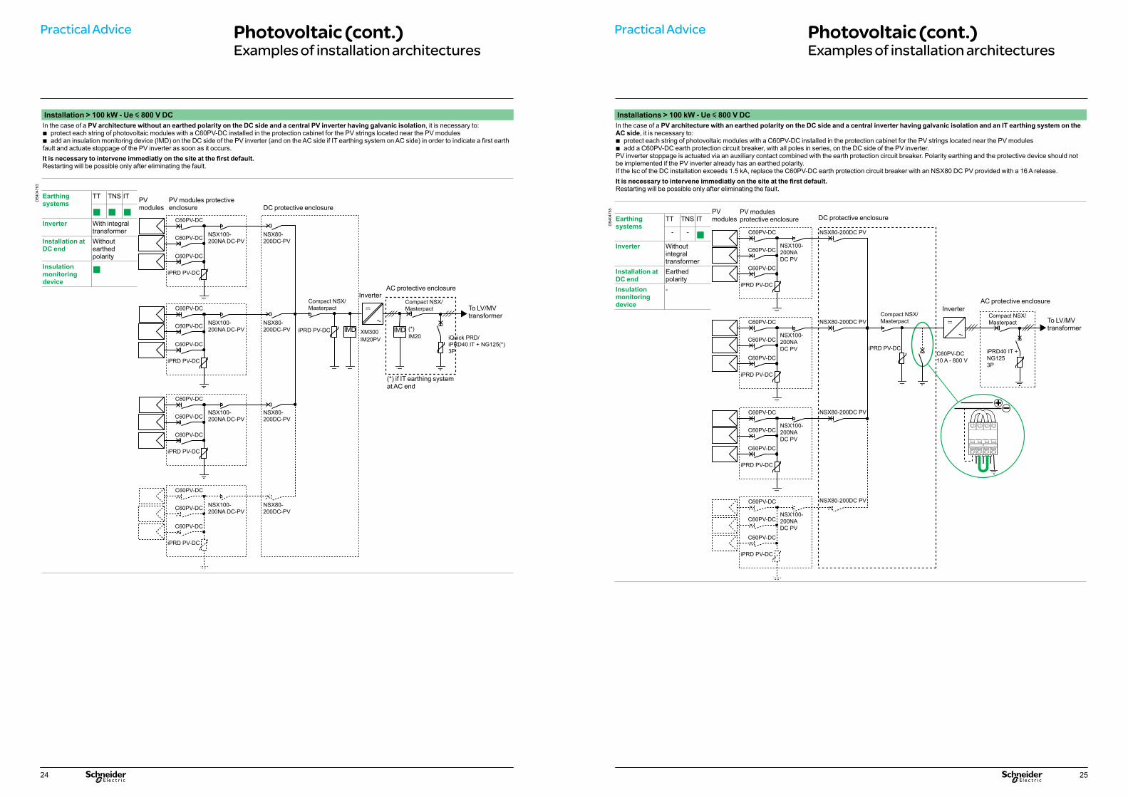
Installation > 100 kW - Ue y 800 V DCIn the case of a PV architecture without an earthed polarity on the DC side and a central PV inverter having galvanic isolation, it is necessary to:
b protect each string of photovoltaic modules with a C60PV-DC installed in the protection cabinet for the PV strings located near the PV modules b add an insulation monitoring device (IMD) on the DC side of the PV inverter (and on the AC side if IT earthing system on AC side) in order to indicate a first earth
fault and actuate stoppage of the PV inverter as soon as it occurs.It is necessary to intervene immediatly on the site at the first default.Restarting will be possible only after eliminating the fault.
NSX100-200NA DC-PV
NSX100-200NA DC-PV
NSX100-200NA DC-PV
NSX100-200NA DC-PV
NSX80-200DC-PV
NSX80-200DC-PV
NSX80-200DC-PV
NSX80-200DC-PV
Compact NSX/Masterpact
iPRD PV-DC
Compact NSX/Masterpact
iQuick PRD/ iPRD40 IT + NG125(*)3P
C60PV-DC
iPRD PV-DC
C60PV-DC
C60PV-DC
C60PV-DC
iPRD PV-DC
C60PV-DC
C60PV-DC
C60PV-DC
iPRD PV-DC
C60PV-DC
C60PV-DC
C60PV-DC
iPRD PV-DC
C60PV-DC
C60PV-DC
Earthing systems
TT TNS IT
b b bInverter With integral
transformerInstallation at DC end
Without earthed polarity
Insulation monitoring device
b
DB
4047
63
PV modules
PV modules protective enclosure DC protective enclosure
InverterAC protective enclosure
IMD IMDXM300IM20PV
To LV/MV transformer
(*) if IT earthing system at AC end
(*)IM20
Practical Advice Photovoltaic (cont.)Examples of installation architectures
Installations > 100 kW - Ue y 800 V DCIn the case of a PV architecture with an earthed polarity on the DC side and a central inverter having galvanic isolation and an IT earthing system on the AC side, it is necessary to:
b protect each string of photovoltaic modules with a C60PV-DC installed in the protection cabinet for the PV strings located near the PV modules b add a C60PV-DC earth protection circuit breaker, with all poles in series, on the DC side of the PV inverter.
PV inverter stoppage is actuated via an auxiliary contact combined with the earth protection circuit breaker. Polarity earthing and the protective device should not be implemented if the PV inverter already has an earthed polarity.If the Isc of the DC installation exceeds 1.5 kA, replace the C60PV-DC earth protection circuit breaker with an NSX80 DC PV provided with a 16 A release.It is necessary to intervene immediatly on the site at the first default.Restarting will be possible only after eliminating the fault.
NSX100-200NADC PV
NSX100-200NADC PV
NSX100-200NADC PV
NSX80-200DC PV
NSX80-200DC PV
NSX80-200DC PV
Compact NSX/Masterpact
iPRD PV-DCC60PV-DC10 A - 800 V
C60PV-DC
iPRD PV-DC
C60PV-DC
C60PV-DC
C60PV-DC
iPRD PV-DC
C60PV-DC
C60PV-DC
NSX100-200NADC PV
NSX80-200DC PVC60PV-DC
iPRD PV-DC
C60PV-DC
C60PV-DC
C60PV-DC
iPRD PV-DC
C60PV-DC
C60PV-DC
Compact NSX/Masterpact
iPRD40 IT + NG1253P
+
Earthing systems
TT TNS IT
- - bInverter Without
integral transformer
Installation at DC end
Earthed polarity
Insulation monitoring device
-
DB
4047
65 PV modules
PV modules protective enclosure DC protective enclosure
InverterAC protective enclosure
To LV/MV transformer

Make the most of your energy
© 2
011
Schn
eide
r Ele
ctric
. All r
ight
s re
serv
ed.
May 2012LVPED208013EN
SEIMLVB12
HeadquartersSchneider Electric Industries (M) Sdn Bhd (378576-M)No. 11, Jalan U1/19, Seksyen U1Hicom-Glenmarie Industrial Park40150 Shah Alam, Selangor, MalaysiaTel : (603) 7883 6333Fax : (603) 7883 6188Email : [email protected] : www.schneider-electric.com.myCustomer Care Centre : 1-800-880-877
Nationwide BranchesJohor BahruTel : (607) 351 3801 / 02Fax : (607) 351 4113 IpohTel : (605) 527 1375Fax : (605) 527 1375
PenangTel : (604) 643 8187 / 75Fax : (604) 643 9197 Kota KinabaluTel : (6088) 237 000 / 12Fax : (6088) 216 900
KuchingTel : (6082) 450 242 Fax : (6082) 450 373 KuantanTel : (609) 567 3636Fax : (609) 566 0688