
Metal foams as flow field and gas diffusion layer in...
9
Journal of Power Sources 165 (2007) 49–57 Metal foams as flow field and gas diffusion layer in direct methanol fuel cells Srikanth Arisetty, Ajay K. Prasad, Suresh G. Advani ∗ Fuel Cell Research Laboratory, Department of Mechanical Engineering, University of Delaware, Newark, DE 19716, USA Received 27 October 2006; received in revised form 3 December 2006; accepted 5 December 2006 Available online 15 December 2006 Abstract Metal foams are routinely used in structures to enhance stiffness and reduce weight over a range of platforms. In direct methanol fuel cells, the controlled porosity and high electrical conductivity of metal foams provide additional benefits. Performance studies were conducted with direct methanol fuel cells incorporating metal foams as the flow field. The influence of the foam pore size and density on cell performance was investigated. The performance of similar density metal foams but with different pore sizes was non-monotonic due to the opposing trends of electrical contact and CO 2 removal with pore size. In contrast, for metal foams with the same in-plane pore size, the performance improved with increasing density. Because the cell operates in a diffusion-dominated regime, its performance showed a strong dependence on methanol concentration and a moderate dependence on methanol flow rate. The feasibility of using metal foams as a gas diffusion layer (GDL) was also explored. © 2006 Elsevier B.V. All rights reserved. Keywords: Direct methanol fuel cells; Metal foam; Gas diffusion layer; Bipolar plates; Multifunctional; Composites 1. Introduction Direct Methanol fuel cells are a promising power source for a range of portable and low power applications. Many power sys- tems such as those used by the military require optimization in power generation, energy storage and material usage. Examples include energy conversion devices for soldier-portable sens- ing equipment and communication devices, next-generation ground vehicles utilizing hybrid power trains, or unmanned aerial vehicles or robotic applications whose current range and performance is severely curtailed by battery life [1,2]. As many of these systems incorporate structural and/or armor materials, important system-level weight/volume savings can be realized by employing multifunctional materials that simultaneously offer both power generation or energy storage capabilities along with structural enhancement [2]. Such multifunctional compos- ites can combine multiple functions in a single component. For example, the core in a composite sandwich structure can also serve as components of a direct methanol fuel cell (DMFC) and provide auxiliary power. ∗ Corresponding author. Tel.: +1 302 831 8975; fax: +1 302 831 3619. E-mail address: [email protected] (S.G. Advani). Core materials such as open cellular metal foams possess good structural and conductive properties and can therefore replace bipolar plates in fuel cells. The bipolar plate physi- cally separates individual fuel cells in a stack while electrically connecting them, and directs fuel and oxidant gas streams to individual cells [3,9–11]. Traditionally, they are machined from graphite and designed for maximum performance and power density. Several types of channel configurations have been used for the gas flow field in bipolar plates [3–6]. These include parallel, serpentine, multiple serpentine, interdigitated, and frac- tional flow fields. However, graphite being brittle yields a system design that is not optimized for structural strength. For struc- tural performance and weight savings, graphite plates can be replaced with open cellular metal foams [2]. In this design, a traditional MEA is sandwiched between two metal foam flow fields and covered with a composite skin, resulting in a strong lightweight structural element that can also produce auxiliary power (Fig. 1). Moreover, foams with a wide range of structural properties and permeabilities can be fabricated with ease to meet the multifunctional requirements of the chosen application. Apart from structural properties, compared to traditional flow fields, metal foams offer advantages in enhancing two-phase flow and current-collecting capacity. For example, efficient removal of carbon dioxide at high current densities is an impor- 0378-7753/$ – see front matter © 2006 Elsevier B.V. All rights reserved. doi:10.1016/j.jpowsour.2006.12.008
-
Upload
truonghanh -
Category
Documents
-
view
219 -
download
0
Transcript of Metal foams as flow field and gas diffusion layer in...
A
cmTaBd©
K
1
rtpiigapoibowiesp
0d
Journal of Power Sources 165 (2007) 49–57
Metal foams as flow field and gas diffusion layer indirect methanol fuel cells
Srikanth Arisetty, Ajay K. Prasad, Suresh G. Advani ∗Fuel Cell Research Laboratory, Department of Mechanical Engineering, University of Delaware, Newark, DE 19716, USA
Received 27 October 2006; received in revised form 3 December 2006; accepted 5 December 2006Available online 15 December 2006
bstract
Metal foams are routinely used in structures to enhance stiffness and reduce weight over a range of platforms. In direct methanol fuel cells, theontrolled porosity and high electrical conductivity of metal foams provide additional benefits. Performance studies were conducted with directethanol fuel cells incorporating metal foams as the flow field. The influence of the foam pore size and density on cell performance was investigated.he performance of similar density metal foams but with different pore sizes was non-monotonic due to the opposing trends of electrical contact
nd CO2 removal with pore size. In contrast, for metal foams with the same in-plane pore size, the performance improved with increasing density.ecause the cell operates in a diffusion-dominated regime, its performance showed a strong dependence on methanol concentration and a moderateependence on methanol flow rate. The feasibility of using metal foams as a gas diffusion layer (GDL) was also explored.2006 Elsevier B.V. All rights reserved.
r plate
grccigdfptdtrtfil
eywords: Direct methanol fuel cells; Metal foam; Gas diffusion layer; Bipola
. Introduction
Direct Methanol fuel cells are a promising power source for aange of portable and low power applications. Many power sys-ems such as those used by the military require optimization inower generation, energy storage and material usage. Examplesnclude energy conversion devices for soldier-portable sens-ng equipment and communication devices, next-generationround vehicles utilizing hybrid power trains, or unmannederial vehicles or robotic applications whose current range anderformance is severely curtailed by battery life [1,2]. As manyf these systems incorporate structural and/or armor materials,mportant system-level weight/volume savings can be realizedy employing multifunctional materials that simultaneouslyffer both power generation or energy storage capabilities alongith structural enhancement [2]. Such multifunctional compos-
tes can combine multiple functions in a single component. For
xample, the core in a composite sandwich structure can alsoerve as components of a direct methanol fuel cell (DMFC) androvide auxiliary power.∗ Corresponding author. Tel.: +1 302 831 8975; fax: +1 302 831 3619.E-mail address: [email protected] (S.G. Advani).
ppt
fiflr
378-7753/$ – see front matter © 2006 Elsevier B.V. All rights reserved.oi:10.1016/j.jpowsour.2006.12.008
s; Multifunctional; Composites
Core materials such as open cellular metal foams possessood structural and conductive properties and can thereforeeplace bipolar plates in fuel cells. The bipolar plate physi-ally separates individual fuel cells in a stack while electricallyonnecting them, and directs fuel and oxidant gas streams tondividual cells [3,9–11]. Traditionally, they are machined fromraphite and designed for maximum performance and powerensity. Several types of channel configurations have been usedor the gas flow field in bipolar plates [3–6]. These includearallel, serpentine, multiple serpentine, interdigitated, and frac-ional flow fields. However, graphite being brittle yields a systemesign that is not optimized for structural strength. For struc-ural performance and weight savings, graphite plates can beeplaced with open cellular metal foams [2]. In this design, araditional MEA is sandwiched between two metal foam flowelds and covered with a composite skin, resulting in a strong
ightweight structural element that can also produce auxiliaryower (Fig. 1). Moreover, foams with a wide range of structuralroperties and permeabilities can be fabricated with ease to meethe multifunctional requirements of the chosen application.
Apart from structural properties, compared to traditional flowelds, metal foams offer advantages in enhancing two-phaseow and current-collecting capacity. For example, efficientemoval of carbon dioxide at high current densities is an impor-

50 S. Arisetty et al. / Journal of Power Sources 165 (2007) 49–57
tural c
ta(etltAcff
sSiptTfeGctMttttcGmm
is
wftsrWf
Dsmtme
2
2
cwtwt
Fig. 1. Cross-section of a multifunctional struc
ant factor that influences the performance of DMFCs. Threenode flow field functions can influence the cell performance:i) the anode flow field supplies methanol to the membranelectrode assembly. To enhance performance, the methanolransport to the catalyst layer should be maximized whileimiting crossover to the cathode through the membrane; (ii)he anode flow field should efficiently remove carbon dioxide.n accumulation of CO2 bubbles near the MEA can reduce the
ell performance [5,7]; (iii) the anode flow field collects currentrom the gas diffusion layer (GDL). Effective current collectionrom the GDL would also enhance performance.
Arico et al. [4] compared the performances obtained usingerpentine and interdigitated channels as flow fields in DMFCs.cott et al. [5] studied the performance characteristics with var-
ous steel meshes as flow beds. Other groups have conductedreliminary investigations using porous flow fields for the reac-ant H2 in proton exchange membrane fuel cell (PEMFC) [3,8].he current study uses metal foams, as the porous flow field
or DMFCs. Methanol must flow through the GDL as it trav-ls towards the catalyst layer from the flow field. Therefore, theDL also plays a major role in determining the mass transfer
haracteristics. Literature suggests that carbon cloth has bet-er gas management characteristics than carbon paper [12,13].
etal foams are porous and conducting, and hence could poten-ially also perform the functions typically required of the GDL,hus introducing the possibility of eliminating the GDL fromhe fuel cell assembly. Accordingly, metal foam consisting ofwo distinct layers possessing different pore sizes (larger pores
onstituting the flow field, and smaller pores replacing theDL) can be placed in direct contact with the catalyst-coatedembrane. Pore size can be tailored to improve the cell perfor-ance. Oedeggard et al. [12] have performed various studiesamst
Fig. 2. Transparent operational DMFC inc
omposite fuel cell (with permission from [2]).
n DMFCs by changing the GDL type and hence the poretructure.
It should be noted that metal foams should be selected toithstand the strong corrosive environment prevalent within the
uel cell. Electrons released during the reaction travel throughhe metal foam due to the potential difference developed. Con-equently, there exists the possibility of an electrochemicaleaction between the methanol solution and the metal foam.
hile Cu, Al and Ni are common materials selected for metaloams, sensitivity to such reaction is the lowest with Ni.
In the present work, we have examined the performance of aMFC in which metal foams with different pore size and density
erve as the flow field. We also report on studies using two-layeretal foam with different pore sizes that serve the functions of
he flow field and the GDL, respectively. Finally, we examine theetal foams after a period of use in the DMFC with a scanning
lectron microscope (SEM) for indications of corrosion.
. Experimental details
.1. DMFC components and assembly
The cell employed in our experiments was designed and fabri-ated in our laboratory (Fig. 2). A commercially available MEAith carbon cloth GDL on either side was sandwiched between
wo square plates of metal foams that serve as the flow field, asell as the current collectors. Carbon cloth GDL enhances the
ransport of the two-phase flow (CO2 bubbles and methanol),
nd it cushions the contact between the catalyst layer and theetal foam. The anode catalyst loading was 4 mg cm−2 carbon-upported 1:1 Pt–Ru, with 2 mg cm−2 carbon-supported Pt onhe cathode side. The polymer electrolyte membrane was Nafion
orporating metal foams as flow field.

S. Arisetty et al. / Journal of Power Sources 165 (2007) 49–57 51
F Cross(
1Ftssaiofmsut
titttf
2
avm
ep
rrtsdtwb16adaw
Gumpc
ig. 3. Metal foams: (a) 10, 20 and 40 ppi (left to right) with 6–8% density. (b)c) SEM image of 20 ppi metal foam.
17, and the active area of the MEA was 25 cm2. As shown inig. 2, the methanol enters the metal foam from a spanwise
rench inlet cut into the foam at its upstream end; methanol isupplied to this trench from a manifold containing five equi-paced holes. The methanol then travels away from the trenchlong the in-plane direction of the foam and exits through a sim-lar spanwise trench at the downstream end. Aluminum platesf 4.72 mm thickness were machined to friction fit the metaloam of dimensions 50.8 mm × 50.8 mm × 6.35 mm. These alu-inum plates were designed to support the metal foams and
erve as current collectors. The cell temperature was controlledsing two electrical heating plates (250 W) positioned againsthe cell retaining end plates.
One challenging aspect of the design was to prevent damageo the membrane from the rough metal foam surface. Accord-ngly, 3.17 mm thick gaskets were placed between the MEA andhe aluminum plate to absorb the stresses during tightening ofhe screws while assembling the cell. An important design fea-ure of our cell is that the anode side is made transparent to allowor direct visualization of the two-phase flow dynamics.
.2. Flow field design and GDL
Two sets of experiments were conducted. In one set, theluminum metal foam was used as the flow field with con-entional GDLs. In the second set, in addition to aluminumetal foam serving as the flow field, the GDL was replaced by
s((1
sectional view of 6–8, 12–16 and 18–24% density (bottom to top) with 20 ppi.
ither a stainless steel mesh, or nickel metal foam with smallerores.
For the first set of experiments, cell performance wasecorded for five different aluminum foams used as the flow fieldepresenting different densities and pore sizes (Fig. 3). Three ofhem had pores per linear inch (ppi) of 10, 20 and 40, with a den-ity of 6–8%. The remaining two foams had a ppi of 20, withensities of 12–16 and 18–24%, respectively. The ppi charac-erizes the pore size of the foam. Foam density is defined as theeight fraction of the foam with respect to a solid aluminumlock occupying the same volume as the foam. Foams with2–16 and 18–24% density are fabricated by compressing the–8% density foams by a factor of two and three, respectively,long the thickness direction. Typically, metal foams with 6–8%ensity are isotropic in nature, whereas higher density foams arenisotropic. The pore size in the in-plane direction for foamsith different densities does not change for the same ppi.Traditionally, carbon cloth and carbon paper are used as
DLs in fuel cells. The second set of experiments explored these of alternate GDL materials such as a stainless steel metalesh, and Ni metal foam of very high ppi, and compared their
erformance with traditional carbon cloth GDL. Hence, this setonsisted of tests with the following three GDLs: (i) stainless
teel mesh (316 stainless steel, 72 ppi, 0.094 mm wire diameter)ii) Ni foam (2 mm thick with 94 ppi, and 95% porosity); andiii) AvcarbTM 1071HCB carbon cloth (17.3–21.3 warp cm−1,6.5–20.5 fill cm−1). In all the three cases, 40 ppi, 6–8% density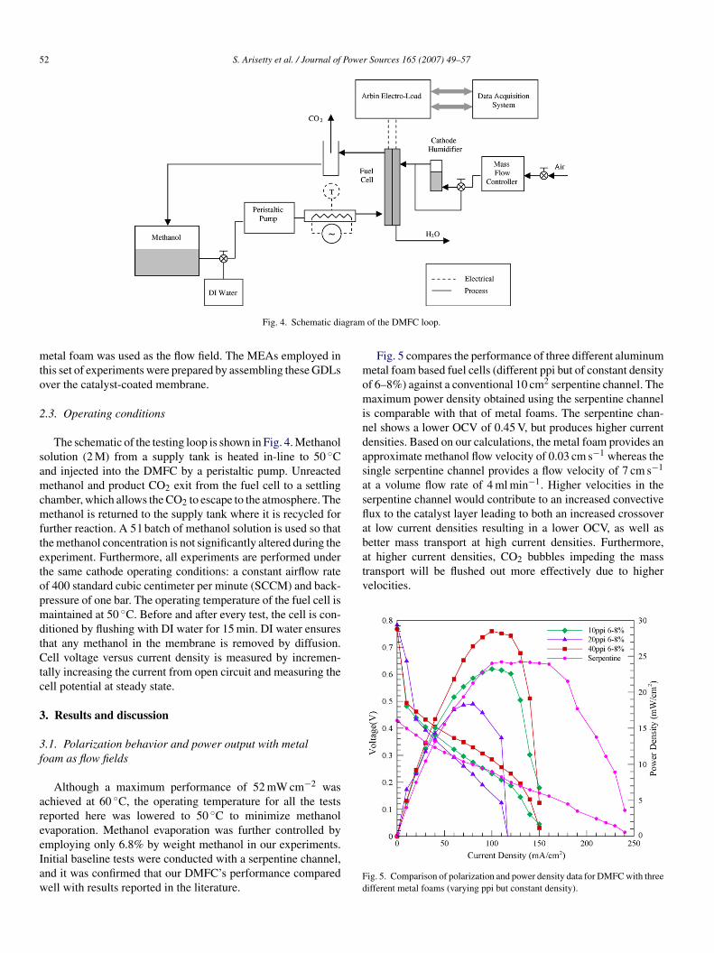
52 S. Arisetty et al. / Journal of Power Sources 165 (2007) 49–57
agram
mto
2
samcmftetopmdtCtc
3
3f
areeIaw
momindasasflabetter mass transport at high current densities. Furthermore,at higher current densities, CO2 bubbles impeding the masstransport will be flushed out more effectively due to highervelocities.
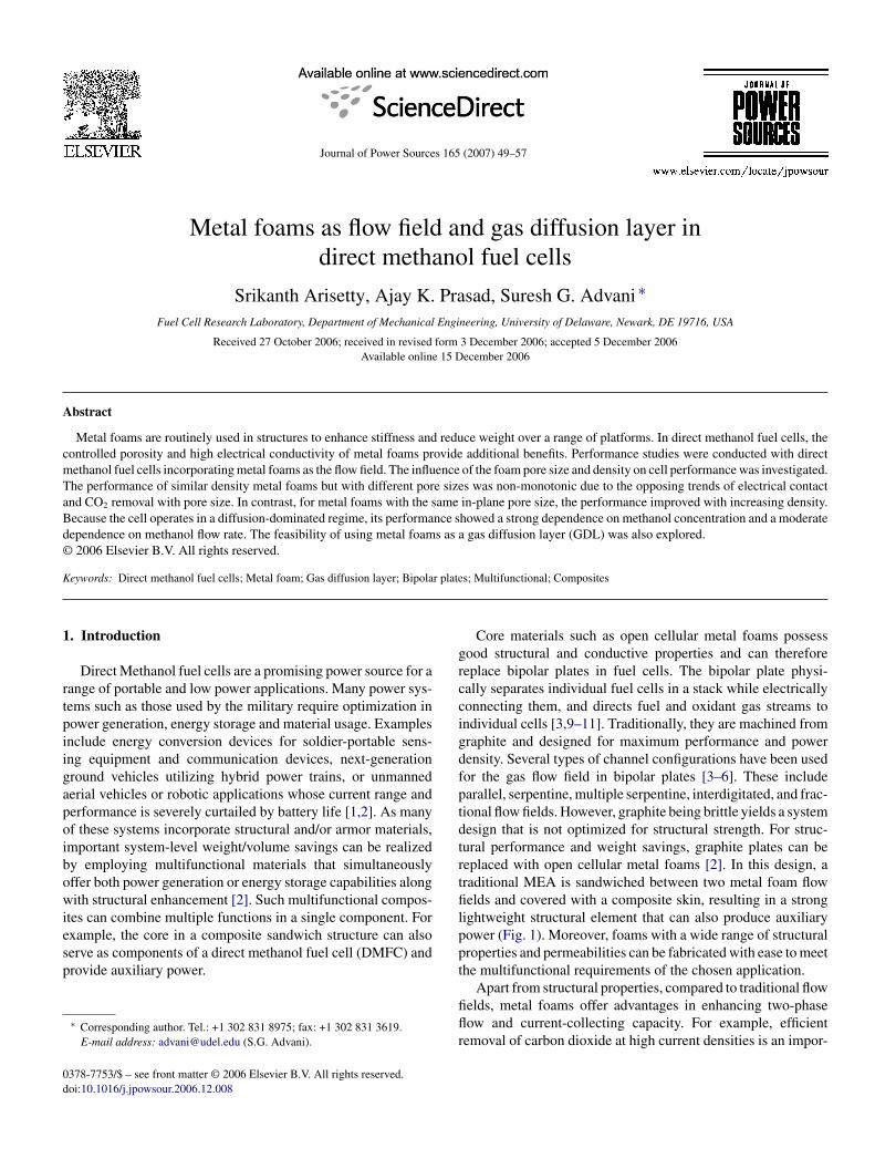
Fig. 4. Schematic di
etal foam was used as the flow field. The MEAs employed inhis set of experiments were prepared by assembling these GDLsver the catalyst-coated membrane.
.3. Operating conditions
The schematic of the testing loop is shown in Fig. 4. Methanololution (2 M) from a supply tank is heated in-line to 50 ◦Cnd injected into the DMFC by a peristaltic pump. Unreactedethanol and product CO2 exit from the fuel cell to a settling
hamber, which allows the CO2 to escape to the atmosphere. Theethanol is returned to the supply tank where it is recycled for
urther reaction. A 5 l batch of methanol solution is used so thathe methanol concentration is not significantly altered during thexperiment. Furthermore, all experiments are performed underhe same cathode operating conditions: a constant airflow ratef 400 standard cubic centimeter per minute (SCCM) and back-ressure of one bar. The operating temperature of the fuel cell isaintained at 50 ◦C. Before and after every test, the cell is con-
itioned by flushing with DI water for 15 min. DI water ensureshat any methanol in the membrane is removed by diffusion.ell voltage versus current density is measured by incremen-
ally increasing the current from open circuit and measuring theell potential at steady state.
. Results and discussion
.1. Polarization behavior and power output with metaloam as flow fields
Although a maximum performance of 52 mW cm−2 waschieved at 60 ◦C, the operating temperature for all the testseported here was lowered to 50 ◦C to minimize methanolvaporation. Methanol evaporation was further controlled by
mploying only 6.8% by weight methanol in our experiments.nitial baseline tests were conducted with a serpentine channel,nd it was confirmed that our DMFC’s performance comparedell with results reported in the literature.Fd
of the DMFC loop.
Fig. 5 compares the performance of three different aluminumetal foam based fuel cells (different ppi but of constant density
f 6–8%) against a conventional 10 cm2 serpentine channel. Theaximum power density obtained using the serpentine channel
s comparable with that of metal foams. The serpentine chan-el shows a lower OCV of 0.45 V, but produces higher currentensities. Based on our calculations, the metal foam provides anpproximate methanol flow velocity of 0.03 cm s−1 whereas theingle serpentine channel provides a flow velocity of 7 cm s−1
t a volume flow rate of 4 ml min−1. Higher velocities in theerpentine channel would contribute to an increased convectiveux to the catalyst layer leading to both an increased crossovert low current densities resulting in a lower OCV, as well as
ig. 5. Comparison of polarization and power density data for DMFC with threeifferent metal foams (varying ppi but constant density).

Power Sources 165 (2007) 49–57 53
tifdeoipsobrbt
p
R
wGtWft
bfai0EmcHewdflcpwte
3
1Ftpt
Fd
idsitaardctms
bttlsTmnc
3p
rmmfl
S. Arisetty et al. / Journal of
The cell using 40 ppi gave the best performance. A monotonicrend in performance with ppi was not observed. The variationn the architecture of the foam produces different mass trans-er and conductive characteristics. A larger pore size promotesetachment of CO2 bubbles from the GDL, allowing for morefficient removal of CO2, and therefore more efficient transportf reactant to the catalyst sites. Hence, mass transfer character-stics improve as the pore size increases (i.e. decreasing order ofpi from 40 and 20 to 10 ppi). On the other hand, a larger poreize implies that electrons must travel larger in-plane distancesvercoming larger electrical resistances along the cloth surfaceefore they can be collected by the nearest rib of the metal foam,esulting in less effective current collection. This is significantecause the in-plane resistance of the carbon cloth can exceedhe through-plane resistance [5].
The above hypothesis can be supported as follows: the in-lane and through-plane resistances are given by
I ≈ ρIL
Wt, RT ≈ ρTt
WL(1)
here R and ρ represents the resistance and resistivity of theDL, respectively. Subscripts I and T refer to in-plane and
hrough-plane, respectively; t is the thickness of the GDL, andand L correspond to the in-plane dimensions of the metal
oam pore in contact with the GDL. The ratio of the in-plane tohrough-plane resistances can be expressed as
RI
RT≈ ρI
ρT
L2
t2 (2)
The maximum in-plane distance traversed by the electronefore it reaches the nearest rib is the pore-size of the metaloam, so L ≈ pore size. Since, we are using the same MEA inll of our experiments the thickness of the GDL = 0.3 mm. Then-plane and through-plane resistivity is reported as 0.0065 and.071 � cm, respectively [16]. Using these values, the ratio inq. (2) is calculated to be 6, 1.5 and 0.4 for 10, 20 and 40 ppietal foams, respectively. Eq. (1) indicates that the effective
urrent collection capability improves monotonically with ppi.owever, the detachment and transport of bubbles which influ-
nces the effective mass transfer to the catalyst sites decreasesith ppi. While this decrease is monotonic, it may be non-linearue to the complicated interplay of surface tension, wettability,ow-induced shear, bubble breakup, and so on. Therefore, theombined effect of current collection and bubble removal couldresent a complex and non-monotonic variation of performanceith ppi in the range investigated here (10–40 ppi). However,
he explanation provided is qualitative. It would be difficult tostimate each phenomenon quantitatively.
.2. Effect of foam density on cell performance
The trend in performance with increasing densities of 6–8,2–16, and 18–24% at a constant pore size of 20 ppi is shown in
ig. 6. Higher density foams possess a smaller pore size in thehrough-plane direction, but the same in-plane pore size, thusreserving a constant contact area between the metal foam andhe carbon cloth. As a result, the current collecting capability
dcnr
ig. 6. Comparison of polarization and power density data for DMFC with threeifferent metal foam flow fields (constant ppi but varying density).
s same for all the three foams. However, an increase in foamensity reduces its permeability in the in-plane direction andubsequently more methanol would be transported convectivelynto the underlying GDL making it more available for the reac-ion at the catalyst sites. Similarly, an increase in foam densitylso promotes CO2 removal from the underlying GDL and cat-lyst layer and helps to open expose new catalyst sites for theeaction. Therefore, higher convective transport with increasingensity improves the cell performance. Varying the density at aonstant ppi would also affect the gas management characteris-ics of the metal foam. It should be noted that the flow rate of
ethanol through metal foams in this set of experiments is toomall to cause a noticeable effect on crossover.
CO2 bubble growth, detachment, and transport are influencedy the through-plane and in-plane metal foam pore characteris-ics. The metal foam structure will not significantly impede theransport of small bubbles. However, at high current densities,arge quantities of carbon dioxide are produced forming large gaslugs whose movement could be impeded by the metal structure.his interference would be greater in 20 ppi, 18–24% densityetal foam than 20 ppi, 6–8% density metal foams. The combi-
ation of these different effects would influence the polarizationurve in a complex manner at high current densities.
.3. Influence of flow rate and concentration on cellerformance
Experiments were conducted to examine the effect of flowate and concentration (Figs. 7–10) on cell performance withetal foam as the flow field. Fig. 7 indicates that the perfor-ance improved moderately with flow rate for the range ofow rates employed. Typically, at a given cell voltage, current
ensity increases as one increases the anode flow rate up to aertain saturation point, beyond which the anode flow rate haso noticeable effect [14]. Therefore, we conclude that the flowates employed in our experiments were below the saturation
54 S. Arisetty et al. / Journal of Power Sources 165 (2007) 49–57
F4r
ppi
Dmt
U
hpG
Fs(
Ff4
aai33nsdiffusion-dominated. Why then do we see an improvement in
ig. 7. Comparison of polarization and power density data for DMFC with0 ppi, 6–8% metal foam flow field for 2 M methanol and three different flowates.
oint. While the polarization curves in Fig. 7 indicate that, theerformance improves with flow rate, at the same time the OCVs reduced due to increased crossover.
The velocity of methanol in the GDL can be estimated usingarcy’s law, which is based on the theory of flow through porousedia; therefore, for the foam as the flow field, the velocity in
he underlying GDL is
G = UFKG
KF(3)
ere U refers to the velocity of methanol, and K refers to theermeability of the medium. Subscripts G and F refer to theDL and foam, respectively. We estimate UF ≈ 0.03 cm s−1
ig. 8. Comparison of polarization data for DMFC with 40 ppi, 6–8% den-ity metal foam as the flow field with convective mass transport held constantconcentration × flow rate).
ptW
Fmo
ig. 9. Comparison of polarization for DMFC with 40 ppi, 6–8% density metaloam flow field for three different concentrations, at a constant flow rate ofml min−1.
t a flow rate of 4 ml min−1, with, KG ≈ 3 × 10⁻¹² m2 [16],nd KF ≈ 3 × 10⁻⁸ m2 [15]. Thus, the velocity of the methanoln the underlying GDL can be calculated using Eq. (3) as× 10−6 cm s−1. Taking the diffusivity of methanol in water as× 10−5 cm2 s−1 and the GDL thickness as 0.3 mm, the Pecletumber is estimated to be 0.003. Since the Peclet number is muchmaller than unity, we conclude that the methanol transport is
erformance with flow rate in Fig. 7? We believe that this is dueo the more effective removal of product CO2 at higher flow rates.
e confirmed diffusion dominance by conducting experiments
ig. 10. Comparison of polarization data for DMFC with 40 ppi, 6–8% densityetal foam flow field for three different concentrations, at a constant flow rate
f 8 ml min−1.

S. Arisetty et al. / Journal of Power Sources 165 (2007) 49–57 55
s steel
iv(otr
tataocscof
ae
3G
tfient
ttgd
In the final aspect of this study, we compared cell performanceby using a stainless steel metal mesh, and a 94 ppi Ni metal foamas GDL, with a conventional carbon cloth GDL (Fig. 11). Theflow field in all three cases was 40 ppi metal foam. Fig. 12 com-
Fig. 11. Microscope images of carbon cloth GDL (top), stainles
n which the concentrations and flow rates were simultaneouslyaried in a manner such that their product remained constantFig. 8). We see now that the performance depends stronglyn concentration. Furthermore, the effect of increased concen-ration on performance overwhelms the effect of reduced flowate.
Figs. 9 and 10 demonstrate the effect of methanol concen-ration on performance for cells operating at flow rates of 4nd 8 ml min−1, respectively. As expected, higher concentra-ion enhances both the diffusive and convective mass fluxes,nd hence a direct dependence on performance is generallybserved. However, Fig. 10 indicates that the 1 M, 8 ml min−1
ell performs better than the 2 M, 8 ml min−1 cell for current den-ities up to 70 mA cm−2. This can be attributed to the enhancedrossover of methanol at lower current densities. Therefore, anptimal value of concentration and flow rate needs to be chosenor the best performance.
We may conclude from these results that when metal foamsre used as the flow field in DMFC, better performance is gen-rally obtained by operating at higher concentrations.
.4. Polarization behavior and power output with variousDL
Oedegaard et al. [12] reported that carbon cloth performs bet-er than carbon paper for DMFC with a single serpentine flow
eld. He found that wet proofing (treating with PTFE) accel-rates CO2 transport through the GDL. Wet proofing creates aetwork of small and large pores in the GDL, allowing CO2o escape through the large pores while methanol transportsF4c
mesh (left), and Ni metal foam (right) after use in the fuel cell.
hrough the small pores [12]. Although adding PTFE reduceshe conductivity of the carbon cloth reducing the overall current,reater benefits are realized by minimizing current oscillationsue to more stable CO2 removal.
ig. 12. Comparison of polarization and power density data for DMFC with0 ppi, 6–8% density foam as the flow field for three different GDLs (i) carbonloth, (ii) Ni metal mesh, and (iii) Ni metal foam with 94 ppi.

5 Powe
pcabcr
pmttsfttukcfwtric
wa
cMlfcmwdeot
3
ta
6 S. Arisetty et al. / Journal of
ares the performance of these two novel diffusion layers witharbon cloth. All three MEAs were fabricated in the same way byssembling the diffusion layer against the catalyst-coated mem-rane. This technique cannot ensure perfect contact between theatalyst-coated membrane and the diffusion layer, and henceesulted in a lower performance.
The stainless steel metal mesh and Ni metal foam show bettererformance compared to the cloth. The literature indicates thatetal mesh as GDL performs better than carbon cloth [12]. The
hree GDLs were viewed under microscope (Fig. 11) after use inhe fuel cell. The pores of the carbon cloth are square with eachide measuring ≈0.1–0.25 mm, whereas the pores of the metaloam are circular with average diameter of 0.15 mm. Hence,he larger (on average) pore dimension of the carbon cloth con-ributes to larger ohmic losses. In addition, upon inspecting thesed five-layer MEAs, we found that the membrane had wrin-led, which could trap pockets of CO2 between the soft carbonloth GDL and the membrane. On the other hand, the rigid metaloam would suppress the entrapment of pockets of CO2, whichould enhance the contact compared to carbon cloth. The elec-
rical conductivity of Ni is 14 times that of carbon cloth furthereducing ohmic losses. Therefore, although the metal foam GDLs thicker than carbon cloth, its increased conductivity and goodontact result in higher performance [17]. Since the pore size
(dfo
Fig. 13. SEM images of two fresh foam samples (bottom), and two foam sam
r Sources 165 (2007) 49–57
ithin the Ni foam is small, contact stresses on the membranere reduced during cell assembly.
Polarization data were collected by maintaining a constanturrent density and measuring the corresponding voltage. TheEAs employed for these experiments were fabricated in our
aboratory. Hence, they are not treated with PTFE, and there-ore a stable current discharge with time is not observed at highurrent densities. However, comparatively we observed that theetal mesh MEA provided the most stable current discharge,hereas the carbon cloth MEA provided the least stable currentischarge. PTFE treatment on metal foams would expectedlynhance the stability of current collection. These experimentspens up the possibility of using metal foams as GDLs comparedo traditional carbon cloth and paper.
.5. Scanning Electron Microscopy inspection of the foam
SEM photos of an unused Al foam sample (Fig. 13, bottomwo images) and Al foam subjected to fuel cell conditions forpproximately 40 h (Fig. 12, top two images) are shown at 1500
left) and 400 (right) magnification. Significant corrosion is evi-ent in the used foams. Spectrum processing of the used metaloam confirmed the presence of large amounts of aluminumxide. The potential difference created across the membrane inples examined after operating in the fuel cell for a long duration (top).

Powe
aiereNs
4
fGpcmHmdptct
eagimimr
A
Da
R
[
[
[
[
S. Arisetty et al. / Journal of
working fuel cell also acts across the metal foam, promot-ng the reaction between the metal foam and methanol, whichxacerbates the corrosion process. Ni is more resistant to cor-osion compared to aluminum. However, Ni foams are morexpensive and less conductive compared to Al foams. Therefore,i-coated aluminum foams would be an appropriate choice for
uch applications.
. Concluding remarks
Performance studies were conducted with direct methanoluel cells incorporating metal foams as the flow field and also asDL. The performance of the metal foam depends on the foamore size and density. The opposite trends in current collectionapability and gas management characteristics cause perfor-ance to behave in a complex manner with varying pore size.owever, increasing the density at a constant pore size promotesethanol transport and CO2 removal in the GDL producing a
irect improvement in performance. We observed an increase inerformance with increasing methanol flow rate and concentra-ion. The strong dependence of performance on methanol con-entration is expected because the transport of methanol withinhe GDL underlying the metal foam is diffusion dominated.
The feasibility of using metal foams as a GDL is alsoxplored. It was found that the metal foams perform betters GDLs compared to cloth and metal mesh. Ni foam hasood electrical conductivity compared to that of carbon clothn which enhances performance. A possible drawback of using
etal foam flow fields is their susceptibility to corrosion. Thisssue must be addressed before they can be effectively used as
ultifunctional composite materials for structural and powerequirements.
[[[
[
r Sources 165 (2007) 49–57 57
cknowledgements
The authors acknowledge the support of the Delawareepartment of Natural Resources and Environmental Control,
nd Army Research Laboratory.
eferences
[1] V. Gogel, T. Frey, Z. Yongsheng, K.A. Friedrich, L. Jorissen, J. Garche, J.Power Sources 127 (2004) 172–180.
[2] J.T. South, R.H. Carter, J.F. Snyder, C.D. Hilton, D.J. O’Brien, E.D. Wetzel,Material Research Society Symposium Proceedings vol. 851, MaterialsResearch Society.
[3] A. Kumar, R.G. Reddy, J. Power Sources 129 (2004) 62–67.[4] A.S. Arico, P. Creti, V. Baglio, E. Modica, V. Antonucci, J. Power Sources
91 (2000) 202–209.[5] K. Scott, P. Argyropoulos, P. Yiannopoulos, W.M. Taama, J. Appl. Elec-
trochem. 31 (2001) 823–832.[6] H. Yang, T.S. Zhao, Electrochim. Acta 50 (2005) 3243–3252.[7] P. Argyropoulos, K. Scott, W.M. Taama, Electrochim. Acta 44 (1999)
3575–3584.[8] A. Kumar, R.G. Reddy, J. Power Sources 114 (2003) 54–62.[9] J. Wind, R. Spah, W. Kaiser, G. Bohm, J. Power Sources 105 (2002)
256–260.10] D.P. Davies, P.L. Adcock, M. Turpin, S.J. Rowen, J. Appl. Electrochem.
30 (2000) 101–105.11] R.C. Makkus, A.H.H. Janseen, F.A. de Bruijn, R.K.A.M. Mallant, J. Power
Sources 86 (2000) 274–282.12] A. Oedeggard, C. Helbling, A. Schmitz, S.M. Holst, R. Tunold, J. Power
Sources 127 (2004) 187–196.13] P. Argyropoulos, K. Scott, W.M. Taama, J. Appl. Electrochem. 29 (1999)
661–669.
14] J. Ge, H. Liu, J. Power Sources 142 (2005) 56–69.15] K.C. Leong, L.W. Jin, Int. J. Heat Mass Transfer 49 (2006) 671–681.16] M. Mathias, J. Roth, J. Fleming, W. Lehnert, Handbook of Fuel Cells, 2000(Chapter 46).17] C. Xu, T.S. Zhao, Q. Ye, Electrochim. Acta 51 (2006) 5524–5531.