
Open Cell Metal Foams for Beam Liners
7
Open Cell Metal Foams for Beam Liners ? R.P. Croce, S. Petracca, A. Stabile * WavesGroup, University of Sannio at Benevento, 82100 Benevento, IT * [email protected] Abstract — The possible use of open-cell metal foams for particle accelerator beam liners is considered. Available materials and modeling tools are reviewed, potential pros and cons are pointed out, and a study program is outlined. 1. INTRODUCTION Molecular gas desorption from the beam-pipe wall due to synchrotron radiation should be properly taken into account in the design of high energy particle accelerators and storage rings. This is spe- cially true for hadron colliders, where nuclear scat- tering in the residual gas, besides limiting the beam luminositity lifetime, may produce high energy pro- tons causing thermal runaway and quenching of su- perconducting magnets. In the CERN Large Hadron Collider [1] a copper- coated stainless-steel beam pipe (or liner) is kept at ≈ 20K by active Helium cooling, and effectively handles the heat load represented by synchrotron radiation, photoelectrons, and image-charge losses. A large number (∼ 10 2 m -1 ) of tiny slots are drilled in the liner wall (see Figure 1) in order to main- tain the desorbed gas densities below a critical level (∼ 10 15 molecules/m 3 for H 2 ) by allowing des- orbed gas to be continuously cryopumped toward the stainless steel cold bore (co-axial to the liner) of the superconducting magnets, which is kept at 1.9K by superfluid Helium. The size, geometry and density of the pumping holes affect the beam dynamics and stability in a way which is synthetically described by the longi- tudinal and transverse beam coupling impedances [2]. The hole geometry should be chosen so as to minimize the effect of trapped (cut-off) modes, and the hole pattern should be designed so as to prevent the possible coherent buildup of synchrotron radia- tion in the TEM waveguide limited by the pipe and the cold bore [3]. Open-cell metal foams could be interesting candi- date materials for beam liner design. In the fol- lowing we give a brief review of their properties, and of the pertinent modeling tools, and draw some preliminary conclusions about the pros and cons of their possible use in beam liners. Figure 1: The LHC slotted copper-plated beam pipe and stainless steel cold bore. 2. OPEN-CELL METAL FOAMS Open-cell metal foams are produced either by vapor- (or electro-) deposition of metal on an open- cell polymer template, followed by polymer burn- off, and a final sintering step to densify the liga- ments. Alternatively, they are obtained by infil- tration/casting of molten metal into a solid mould, consisting of packed (non-permeable) templates of the pores, followed by burn-out and removal of the mould [4]. Both processes result into highly gas- permeable reticulated foams, where only a 3D web of solid conducting struts among the pores survives. The typical structure of these materials is displayed in Figure 2. The key structural parameters of retic- ulated metal foams are the vacuum ”pore” size, and the porosity (volume fraction of pores). Pore sizes arXiv:1307.4779v1 [physics.acc-ph] 17 Jul 2013
Transcript of Open Cell Metal Foams for Beam Liners
Open Cell Metal Foams for Beam Liners ?
R.P. Croce, S. Petracca, A. Stabile*
WavesGroup, University of Sannio at Benevento, 82100 Benevento, IT
Abstract — The possible use of open-cell metal foamsfor particle accelerator beam liners is considered.Available materials and modeling tools are reviewed,potential pros and cons are pointed out, and a studyprogram is outlined.
1. INTRODUCTION
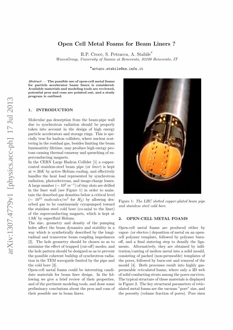
Molecular gas desorption from the beam-pipe walldue to synchrotron radiation should be properlytaken into account in the design of high energyparticle accelerators and storage rings. This is spe-cially true for hadron colliders, where nuclear scat-tering in the residual gas, besides limiting the beamluminositity lifetime, may produce high energy pro-tons causing thermal runaway and quenching of su-perconducting magnets.In the CERN Large Hadron Collider [1] a copper-coated stainless-steel beam pipe (or liner) is keptat ≈ 20K by active Helium cooling, and effectivelyhandles the heat load represented by synchrotronradiation, photoelectrons, and image-charge losses.A large number (∼ 102 m−1) of tiny slots are drilledin the liner wall (see Figure 1) in order to main-tain the desorbed gas densities below a critical level(∼ 1015 molecules/m3 for H2) by allowing des-orbed gas to be continuously cryopumped towardthe stainless steel cold bore (co-axial to the liner)of the superconducting magnets, which is kept at1.9K by superfluid Helium.The size, geometry and density of the pumpingholes affect the beam dynamics and stability in away which is synthetically described by the longi-tudinal and transverse beam coupling impedances[2]. The hole geometry should be chosen so as tominimize the effect of trapped (cut-off) modes, andthe hole pattern should be designed so as to preventthe possible coherent buildup of synchrotron radia-tion in the TEM waveguide limited by the pipe andthe cold bore [3].Open-cell metal foams could be interesting candi-date materials for beam liner design. In the fol-lowing we give a brief review of their properties,and of the pertinent modeling tools, and draw somepreliminary conclusions about the pros and cons oftheir possible use in beam liners.
Figure 1: The LHC slotted copper-plated beam pipeand stainless steel cold bore.
2. OPEN-CELL METAL FOAMS
Open-cell metal foams are produced either byvapor- (or electro-) deposition of metal on an open-cell polymer template, followed by polymer burn-off, and a final sintering step to densify the liga-ments. Alternatively, they are obtained by infil-tration/casting of molten metal into a solid mould,consisting of packed (non-permeable) templates ofthe pores, followed by burn-out and removal of themould [4]. Both processes result into highly gas-permeable reticulated foams, where only a 3D webof solid conducting struts among the pores survives.The typical structure of these materials is displayedin Figure 2. The key structural parameters of retic-ulated metal foams are the vacuum ”pore” size, andthe porosity (volume fraction of pores). Pore sizes
arX
iv:1
307.
4779
v1 [
phys
ics.
acc-
ph]
17
Jul 2
013
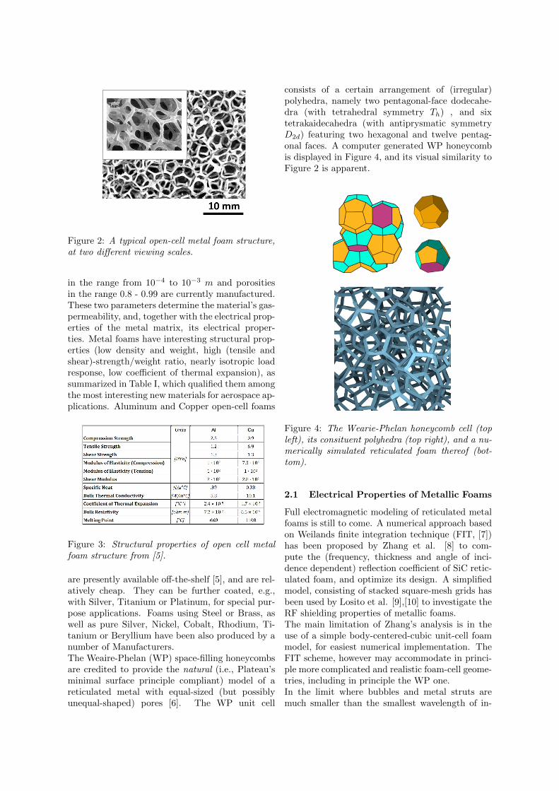
Figure 2: A typical open-cell metal foam structure,at two different viewing scales.
in the range from 10−4 to 10−3 m and porositiesin the range 0.8 - 0.99 are currently manufactured.These two parameters determine the material’s gas-permeability, and, together with the electrical prop-erties of the metal matrix, its electrical proper-ties. Metal foams have interesting structural prop-erties (low density and weight, high (tensile andshear)-strength/weight ratio, nearly isotropic loadresponse, low coefficient of thermal expansion), assummarized in Table I, which qualified them amongthe most interesting new materials for aerospace ap-plications. Aluminum and Copper open-cell foams
Figure 3: Structural properties of open cell metalfoam structure from [5].
are presently available off-the-shelf [5], and are rel-atively cheap. They can be further coated, e.g.,with Silver, Titanium or Platinum, for special pur-pose applications. Foams using Steel or Brass, aswell as pure Silver, Nickel, Cobalt, Rhodium, Ti-tanium or Beryllium have been also produced by anumber of Manufacturers.The Weaire-Phelan (WP) space-filling honeycombsare credited to provide the natural (i.e., Plateau’sminimal surface principle compliant) model of areticulated metal with equal-sized (but possiblyunequal-shaped) pores [6]. The WP unit cell
consists of a certain arrangement of (irregular)polyhedra, namely two pentagonal-face dodecahe-dra (with tetrahedral symmetry Th) , and sixtetrakaidecahedra (with antiprysmatic symmetryD2d) featuring two hexagonal and twelve pentag-onal faces. A computer generated WP honeycombis displayed in Figure 4, and its visual similarity toFigure 2 is apparent.
Figure 4: The Wearie-Phelan honeycomb cell (topleft), its consituent polyhedra (top right), and a nu-merically simulated reticulated foam thereof (bot-tom).
2.1 Electrical Properties of Metallic Foams
Full electromagnetic modeling of reticulated metalfoams is still to come. A numerical approach basedon Weilands finite integration technique (FIT, [7])has been proposed by Zhang et al. [8] to com-pute the (frequency, thickness and angle of inci-dence dependent) reflection coefficient of SiC retic-ulated foam, and optimize its design. A simplifiedmodel, consisting of stacked square-mesh grids hasbeen used by Losito et al. [9],[10] to investigate theRF shielding properties of metallic foams.The main limitation of Zhang’s analysis is in theuse of a simple body-centered-cubic unit-cell foammodel, for easiest numerical implementation. TheFIT scheme, however may accommodate in princi-ple more complicated and realistic foam-cell geome-tries, including in principle the WP one.In the limit where bubbles and metal struts aremuch smaller than the smallest wavelength of in-
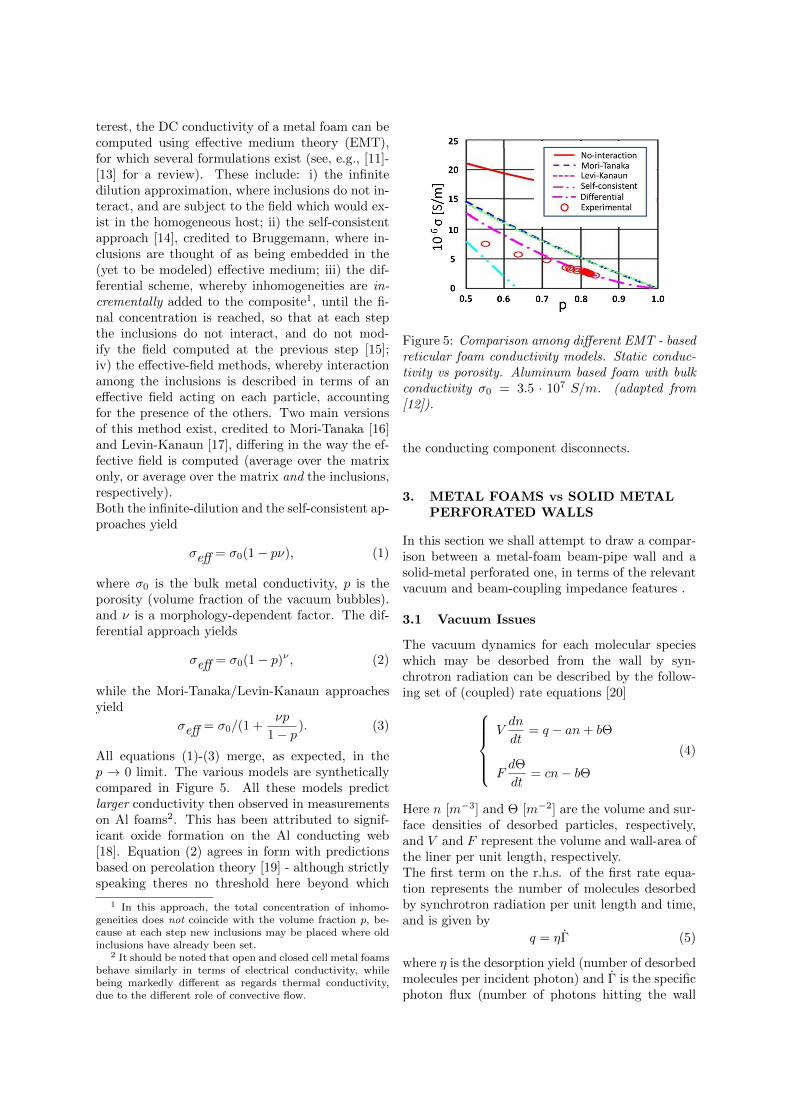
terest, the DC conductivity of a metal foam can becomputed using effective medium theory (EMT),for which several formulations exist (see, e.g., [11]-[13] for a review). These include: i) the infinitedilution approximation, where inclusions do not in-teract, and are subject to the field which would ex-ist in the homogeneous host; ii) the self-consistentapproach [14], credited to Bruggemann, where in-clusions are thought of as being embedded in the(yet to be modeled) effective medium; iii) the dif-ferential scheme, whereby inhomogeneities are in-crementally added to the composite1, until the fi-nal concentration is reached, so that at each stepthe inclusions do not interact, and do not mod-ify the field computed at the previous step [15];iv) the effective-field methods, whereby interactionamong the inclusions is described in terms of aneffective field acting on each particle, accountingfor the presence of the others. Two main versionsof this method exist, credited to Mori-Tanaka [16]and Levin-Kanaun [17], differing in the way the ef-fective field is computed (average over the matrixonly, or average over the matrix and the inclusions,respectively).Both the infinite-dilution and the self-consistent ap-proaches yield
σeff = σ0(1− pν), (1)
where σ0 is the bulk metal conductivity, p is theporosity (volume fraction of the vacuum bubbles).and ν is a morphology-dependent factor. The dif-ferential approach yields
σeff = σ0(1− p)ν , (2)
while the Mori-Tanaka/Levin-Kanaun approachesyield
σeff = σ0/(1 +νp
1− p). (3)
All equations (1)-(3) merge, as expected, in thep → 0 limit. The various models are syntheticallycompared in Figure 5. All these models predictlarger conductivity then observed in measurementson Al foams2. This has been attributed to signif-icant oxide formation on the Al conducting web[18]. Equation (2) agrees in form with predictionsbased on percolation theory [19] - although strictlyspeaking theres no threshold here beyond which
1 In this approach, the total concentration of inhomo-geneities does not coincide with the volume fraction p, be-cause at each step new inclusions may be placed where oldinclusions have already been set.
2 It should be noted that open and closed cell metal foamsbehave similarly in terms of electrical conductivity, whilebeing markedly different as regards thermal conductivity,due to the different role of convective flow.
Figure 5: Comparison among different EMT - basedreticular foam conductivity models. Static conduc-tivity vs porosity. Aluminum based foam with bulkconductivity σ0 = 3.5 · 107 S/m. (adapted from[12]).
the conducting component disconnects.
3. METAL FOAMS vs SOLID METALPERFORATED WALLS
In this section we shall attempt to draw a compar-ison between a metal-foam beam-pipe wall and asolid-metal perforated one, in terms of the relevantvacuum and beam-coupling impedance features .
3.1 Vacuum Issues
The vacuum dynamics for each molecular specieswhich may be desorbed from the wall by syn-chrotron radiation can be described by the follow-ing set of (coupled) rate equations [20]
Vdn
dt= q − an+ bΘ
FdΘ
dt= cn− bΘ
(4)
Here n [m−3] and Θ [m−2] are the volume and sur-face densities of desorbed particles, respectively,and V and F represent the volume and wall-area ofthe liner per unit length, respectively.The first term on the r.h.s. of the first rate equa-tion represents the number of molecules desorbedby synchrotron radiation per unit length and time,and is given by
q = ηΓ (5)
where η is the desorption yield (number of desorbedmolecules per incident photon) and Γ is the specificphoton flux (number of photons hitting the wall
per unit length and time). The second term repre-sents the number of molecules which are removedper unit time and unit length by either sticking tothe wall, or escaping through the holes. The a co-efficient in (4) can be accordingly written
a =〈v〉4
(s+ f)F (6)
where 〈v〉 ≈ (8kT/πm)1/2 is the average molecularspeed, m being the molecular mass, k the Boltz-mann constant ant T the absolute temperature,〈v〉/4 is the average numer of collisions of a sin-gle molecule per unit time and unit wall surface,s is the sticking probability, and fh is the escapeprobability. The third term accounts for thermalor radiation induced re-cycling of molecules stick-ing at the walls. The b coefficient in (4) can beaccordingly written
b = κΓ + Fνo exp(−E/kT ) (7)
Here the first term accounts for radiation inducedrecycling, described by the coefficient κ [m2], whilethe second term describes thermally-activated recy-cling, ν0 being a typical molecular vibrational fre-quency, and E a typical activation energy.The bΘ term appears with reversed sign on ther.h.s. of the second rate equation, where it repre-sents the the number of molecules de-sticking fromthe wall surface per unit time and unit length. Thefirst term on the r.h.s. of this equation representsthe number of molecules sticking to the wall, perunit time and unit length, whence (compare witheq. (6))
c =〈v〉4sF (8)
At equilibrium, n = Θ = 0, and the rate equationsyield:
neq =4ηΓ
〈v〉fF
Θeq =s
f
ηΓ
κΓ + Fνo exp(−E/kT )
(9)
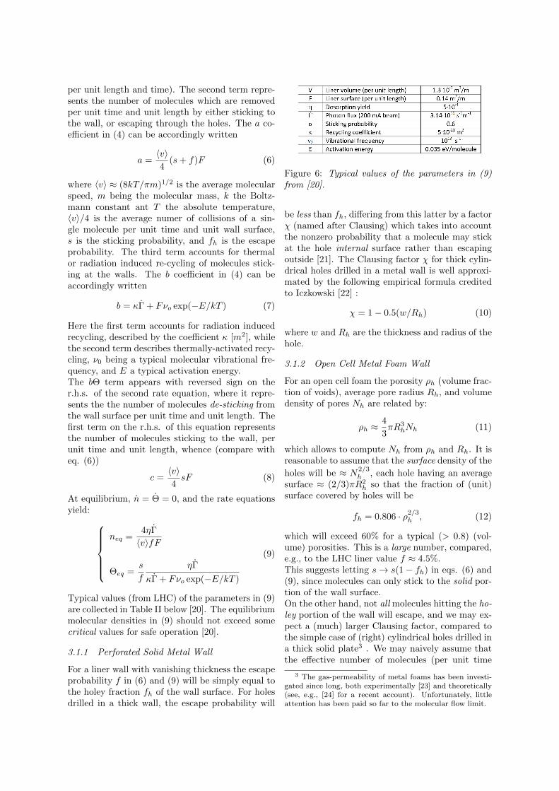
Typical values (from LHC) of the parameters in (9)are collected in Table II below [20]. The equilibriummolecular densities in (9) should not exceed somecritical values for safe operation [20].
3.1.1 Perforated Solid Metal Wall
For a liner wall with vanishing thickness the escapeprobability f in (6) and (9) will be simply equal tothe holey fraction fh of the wall surface. For holesdrilled in a thick wall, the escape probability will
Figure 6: Typical values of the parameters in (9)from [20].
be less than fh, differing from this latter by a factorχ (named after Clausing) which takes into accountthe nonzero probability that a molecule may stickat the hole internal surface rather than escapingoutside [21]. The Clausing factor χ for thick cylin-drical holes drilled in a metal wall is well approxi-mated by the following empirical formula creditedto Iczkowski [22] :
χ = 1− 0.5(w/Rh) (10)
where w and Rh are the thickness and radius of thehole.
3.1.2 Open Cell Metal Foam Wall
For an open cell foam the porosity ρh (volume frac-tion of voids), average pore radius Rh, and volumedensity of pores Nh are related by:
ρh ≈4
3πR3
hNh (11)
which allows to compute Nh from ρh and Rh. It isreasonable to assume that the surface density of the
holes will be ≈ N2/3h , each hole having an average
surface ≈ (2/3)πR2h so that the fraction of (unit)
surface covered by holes will be
fh = 0.806 · ρ2/3h , (12)
which will exceed 60% for a typical (> 0.8) (vol-ume) porosities. This is a large number, compared,e.g., to the LHC liner value f ≈ 4.5%.This suggests letting s→ s(1− fh) in eqs. (6) and(9), since molecules can only stick to the solid por-tion of the wall surface.On the other hand, not all molecules hitting the ho-ley portion of the wall will escape, and we may ex-pect a (much) larger Clausing factor, compared tothe simple case of (right) cylindrical holes drilled ina thick solid plate3 . We may naively assume thatthe effective number of molecules (per unit time
3 The gas-permeability of metal foams has been investi-gated since long, both experimentally [23] and theoretically(see, e.g., [24] for a recent account). Unfortunately, littleattention has been paid so far to the molecular flow limit.
and length) which will escape from a metal-foamwall with thickness w, will be related to the num-ber (per unit time and length) of those entering theface-holes by a Lambert-Beers factor, so that
f = fh exp(−w/`), (13)
reflecting the fact that those molecules may collidewith and stick to the (inner) metal web, instead ofescaping. The obvious requirement that (13) agreeswith (10) in the w → 0 limit yields ` = 2Rh as anestimate of the extinction length in (13).Note that synchrotron radiation will not penetratethe metal foam beyond a few skin-depths δS , so thatnot all molecules sticking to the metal web insidethe metal foam could be recycled by synchrotronradiation. This implies that the value of the recy-cling factor κ in (7) and (9) may be significantlydifferent for a reticular wall.
3.2 Beam Coupling Impedanceand Parasitic Loss
Beam coupling impedances provide a synthetic de-scription of the beam-pipe interaction, for inves-tigating beam dynamics and stability [2]. Forthe simplest case of a circular pipe of radius bwith on-axis beam, the longitudinal beam-couplingimpedance per unit length is given by
Z‖(ω) =Zwall2πb
(14)
where Zwall is the wall impedance, and aLeontovich assumption is implied4. Similarly, thenonzero components of the diagonal transversebeam coupling impedance dyadic are
Z⊥(ω) =cZwallωπb3
(15)
where c is the speed of light in vacuum. Theparasitic loss (energy lost by the beam per unitpipe length) is directly related to the longitudinalimpedance via
∆E =1
2π
∫ +∞
−∞|I(ω)|2<e Z‖(ω)dω. (16)
where I(ω) is the beam-current frequency spectrum[2]. The beam coupling impedances (and parasiticlosses) should not exceed some critical values forsafe operation [1].
4 Equation (14) is a special case of a general formulawhich allows to compute the longitudinal and transversebeam-coupling impedances of a pipe with complicated ge-ometric and constitutive properties [25].
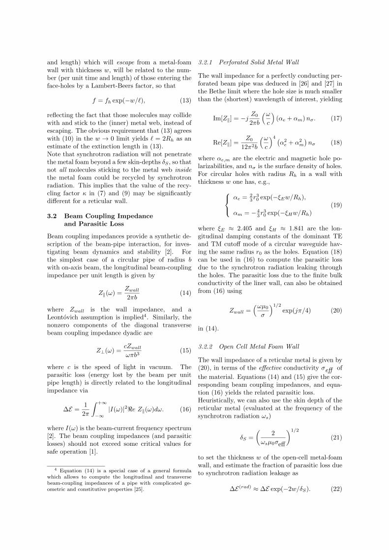
3.2.1 Perforated Solid Metal Wall
The wall impedance for a perfectly conducting per-forated beam pipe was deduced in [26] and [27] inthe Bethe limit where the hole size is much smallerthan the (shortest) wavelength of interest, yielding
Im[Z‖] = −j Z0
2πb
(ωc
)(αe + αm)nσ. (17)
Re[Z‖] =Z0
12π2b
(ωc
)4 (α2e + α2
m
)nσ (18)
where αe,m are the electric and magnetic hole po-larizabilities, and nσ is the surface density of holes.For circular holes with radius Rh in a wall withthickness w one has, e.g., αe = 2
3r30 exp(−ξEw/Rh),
αm = − 43r
30 exp(−ξHw/Rh)
(19)
where ξE ≈ 2.405 and ξH ≈ 1.841 are the lon-gitudinal damping constants of the dominant TEand TM cutoff mode of a circular waveguide hav-ing the same radius r0 as the holes. Equation (18)can be used in (16) to compute the parasitic lossdue to the synchrotron radiation leaking throughthe holes. The parasitic loss due to the finite bulkconductivity of the liner wall, can also be obtainedfrom (16) using
Zwall =(ωµ0
σ
)1/2exp(jπ/4) (20)
in (14).
3.2.2 Open Cell Metal Foam Wall
The wall impedance of a reticular metal is given by(20), in terms of the effective conductivity σeff of
the material. Equations (14) and (15) give the cor-responding beam coupling impedances, and equa-tion (16) yields the related parasitic loss.Heuristically, we can also use the skin depth of thereticular metal (evaluated at the frequency of thesynchrotron radiation ωs)
δS =
(2
ωsµ0σeff
)1/2
(21)
to set the thickness w of the open-cell metal-foamwall, and estimate the fraction of parasitic loss dueto synchrotron radiation leakage as
∆E(rad) ≈ ∆E exp(−2w/δS). (22)
4. CONCLUSIONS
On the basis of the above hints, some preliminaryqualitative conclusions can be drawn about the pos-sible use of reticular metals in beam liners.The structural properties of the material may beadequate to resist to eddy-current induced stresses,in case of superconducting magnets’ failure.For a given out-gassing capacity, a smaller totalsurface of reticular metal may be needed, thanksto the much larger gas permeability of open-cellmetal foams in the molecular-flow regime, com-pared to perforated solid-metal. At the same time,synchrotron radiation leakage could be lower, dueto better EM shielding properties, and the risk ofcoherent beaming of synchrotron radiation in theTEM region between the outer liner wall and thecold bore would be reduced, due to the almost ran-dom hole pattern.Bulk ohmic losses in reticular metals, on the otherhand, may be much larger compared to solid met-als. This could be mitigated to some extent by coat-ing the metallic web, e.g., with a superconductingmaterial.Using, e.g., relatively larg(er) holes/slots in thebeam-liner, backed by metal foam strips could pos-sibly cope with the very stringent vacuum andimpedance requirements of the perspective SLHC[28].In order to translate the above hints into quanti-tative design criteria, further modeling effort andsubstantial experimental work are obviously in or-der.We believe that such a study program is worth be-ing pursued, and that the available modeling toolsand technologies provide a good starting point forits succesful implementation. We are accordinglypreparing a research proposal on the subject to besubmitted to the Italian National Institute for Nu-clear Physics Research (INFN).
References
[1] - ”The Large Hadron Collider Conceptual De-sign,” CERN Rept. AC/95-05 (1995).
[2] B.W. Zotter and S.A. Kheifets, ”Impedancesand Wakes in High Energy Particle Accelera-tors,” World Scientific, Singapore (1998).
[3] S. Heifets and A. Mikhailichenko, ”CoherentSynchrotron Radiation in Multiply ConnectedVacuum Chamber,” SLAC Pub. 8428 (2000).
[4] J. Banhart and N.A. Fleck, ”Cellular Metalsand Metal Foaming Technology,” MIT Press,Boston (2003).
[5] www.ergaerospace.com
[6] D. Weaire and R. Phelan, ”A Counter-Example to Kelvin’s Conjecture on MinimalSurfaces,” Phil. Mag. Lett. 69 (1994) 107.
[7] T. Weiland, ”A Discretization Method forthe Solution of Maxwells Equations for Six-Component Felds,” AEU Int. J. Electr. C31(1977) 116.
[8] H. Zhang et al., ”Numerical Predictions forRadar Absorbing Silicon Carbide Foams Us-ing a Fnite Integration Technique with a Per-fect Boundary Approximation,” Smart Mater.Struct. 15 (2006) 759.
[9] O. Losito et al., ”A Wide-Frequency Model ofMetal Foam for Shielding Applications,” IEEETrans. EMC-52 (2010) 75.
[10] G.Monti, L. Catarinucci and L. Tarricone,”New materials for electromagnetic shielding:Metal foams with plasma properties,” MOTL52 (2010) 1700.
[11] F.G. Cuevas et al., ”Electrical Conductivityand Porosity Relationship in Metal Foams,” J.Porous. Mater. 16 (2008) 675.
[12] I. Sevostianov, J. Kovacic and F. Simancik,”Elastic and Electric Properties of ClosedCell Aluminum Foams,” Mat. Sci. Eng. A420(2006) 87.
[13] R. Goodall, L. Weber and A. Mortensen, ”TheElectrical Conductivity of Microcellular Met-als,” J. Appl. Phys., 100 (2006) 044912.
[14] D.A.G. Bruggemann, ”Berechnung Ver-schiedener Physikalischer Konstanten vonHeterogenen Substanzen,” Ann. Phys. 24(1935) 636.
[15] R. McLaughlin, ”A Study of the DifferentialScheme for Composite Materials,” Int. J. Eng.Sci. 5 (1977) 237.
[16] Y. Qui and G.J. Weng, ”On the Application ofMoriTanaka’s Theory Involving TransverselyIsotropic Spheroidal Inclusions,” Int. J. Eng.Sci. 28 (1990) 1121.
[17] S.K. Kanaun, ”Dielectric Properties of MatrixComposite Materials with High Volume Con-centration of Inclusions (Effective Field Ap-proach),” Int. J. Eng. Sci. 41 (2003) 1287.
[18] T. W. Clyne, Thermal and Electrical Conduc-tion in MMCs, in Comprehensive CompositeMaterials, Elsevier, Amsterdam (2000).
[19] D. Stauffer and A. Aharony, ”Introduction topercolation Theory,” Taylor and Francis, Lon-don (1992).
[20] O. Grobner, ”Overview of the LHC VacuumSystem,” Vacuum 60 (2001) 25.
[21] W. Steckelmacher, ”Knudsen Flow 75 Yearson: the Current State of the Art for Flow ofRarefied Gases in Tubes and Systems,” Rep.Progr. Phys. 49 (1986) 1083.
[22] R.P. Iczkowski, J.L. Margrave and S.M. Robin-son, ”Effusion of Gases through Conical Ori-fices,” J. Phys. Chem. 67 (1963) 229.
[23] B.R.F. Kendall, ”Vacuum Applications ofMetal Foams,” J. Vac. Sci. Technol. 17 (1980)1385.
[24] K. Boomsma, D. Poulikakos and Y. Ventikos,”Simulation of Flow through Open Cell metalFoams using an Idealized Periodic Cell Struc-
ture,” Int. J. Heat and Fluid Flow 24 (2003)825.
[25] S. Petracca, ”Reciprocity Theorem for Cou-pling Impedance Computation in the LHCLiner.,” Part. Acc. 50 (1995) 211.
[26] S.S. Kurrenoy, ”Couling Impedances of Pump-ing Holes,” Particle Accel. 39 (1992) 1.
[27] S. Petracca, ”Beam Coupling Impedances forPerforated Beam Pipes with General Shapefrom Impedance Boundary Conditions,” Phys.Rev. E60 (1999) 6030.
[28] http://care-hhh.web.cern.ch/CARE-HHH/LUMI-06/