MergedFile - DCE · 2017-08-14 · Part – B 1. Write short notes on CAD standards. The purpose of...
25
Transcript of MergedFile - DCE · 2017-08-14 · Part – B 1. Write short notes on CAD standards. The purpose of...


ME6501 – Computer Aided Design
Unit – V
Part – A
1. What are the basic elements associated with a CAD system? i).Operator (user) ii).Graphics support system iii).Other user interface support system iv).Application functions v). Database
2. What are the reasons for evolving graphic standards? i) Need for exchanging graphic data between different computer systems ii) Need for a clear distinction between modeling and review aspects 3. Brief the primary purposes of the Graphical Kernel System (GKS)? (i) To provide for portability of graphics application programs (ii) To aid in the understanding of graphics method by application programs (iii) Provide the guidelines for manufacturers in describing useful graphics capabilities.
4. Define Open Graphics Library? OpenGL (Open Graphics Library)is a cross-language, multi-platform application programming interface (application program interface-API) for rendering 2D and 3D vector graphics. The API is typically used to interact with a graphics processing unit (GPU), to achieve hardware- accelerated rendering.
5. Define Data exchange standards in CAD? CAD data exchange involves a number of software technologies and methods to translate data from one Computer-aided design system to another CAD file format. This PLM technology is required to facilitate collaborative work (CPD) between OEMs and their suppliers. 6. Name the basic methods of transferring data? There are basically three methods of transferring data from one CAD system to another. 1. Direct CAD system export/import 2. Direct 3rd party translators. 3.Intermediate data exchange formats.
7. What is the use of IGES system? The Initial Graphics Exchange Specification (IGES) (pronounced eye-jess) is a file format which defines a vendor neutral data format that allows the digital exchange of information among Computer-aided design (CAD) systems . 8. Mention the different file section in IGES? i)Flag section(optional) ii) Start section(S) iii) Global section(G) iv) Directory entry(D)section v)Parameter Data section vi) Terminal section
9. What is the use of STEP data exchange format? STEP (Standard for the Exchange of Product model data) can be used to exchange data between CAD, computer-aided manufacturing, computer-aided engineering, product data management/enterprise data modeling and other CAx systems. STEP is addressing product data from mechanical and electrical design, geometric dimensioning and tolerancing, analysis and manufacturing, with additional information specific to various industries such as automotive, aerospace, building construction, ship, oil and gas, process plants and others.

10. Mention the requirements of a conformant STEP application? i) Implementation of either a preprocessor or a postprocessor or both ii) using one of the STEP
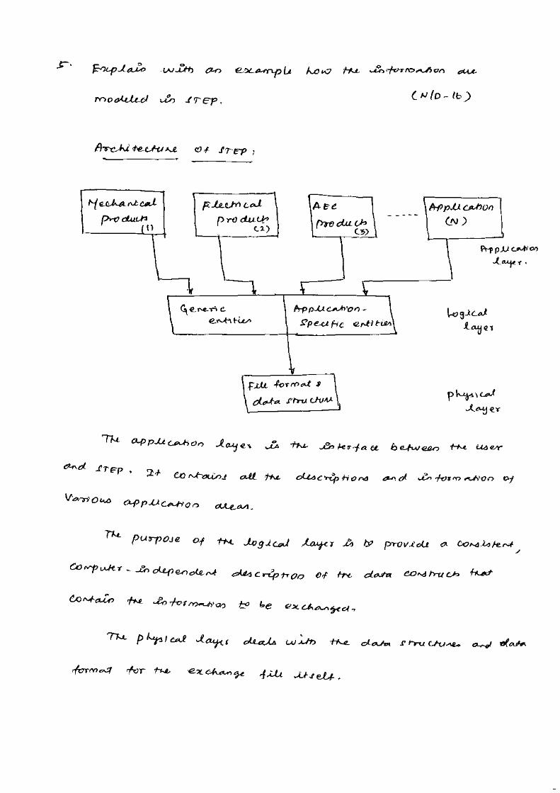
implementation methods STEP-File, STEP-XML or SDAI for the AIM/MIM data model and iii)supporting one or several conformance classes of an AP. 11. What are the three layers of architecture? i) Application layer ii) Logical layer iii) Physical layer 12. What is the need for CALS (Continuous Acquisition and Lifecycle Support)? To establish an integrated system in which any information obtained at each stage (survey, designing, construction and maintenance) of public works should be digitalized so that every person of each section both in public and private sectors could share and re-use the information. 13. What is computer graphics communication? Graphic communication as the name suggests is about communicating through graphics. It is the process of creating and producing drawings or images that get a message across. For example poster advertising is an event, a drawing showing the plans for a building or a 3D computer model showing what a new product will look like. 14. Compare the shape based and the product data based exchange standards. IGES: exchanges primarily shape (both geometric and topological) and non data, which is referred as CAD to CAD exchange STEP: The goal of the standard is to enable the exchange of a computerized model with all of its supporting types of data in a neutral format. 15. What is meant by CAD data exchange? Mention its importance. CAD data exchange involves a number of software technological and methods to translate data from one computer aided design system to another CAD file format. This PLM technology is required to facilitate collaborative work (CPD) between OEM’s and their suppliers. NC programming typically requires that the geometry received from a CAD system. 16. How does PHIGS differ from IGES? PHIGS is an improved version of GKS and CORE. It offers the extended set of primitives for graphical elements from which the models may be generated. It is mainly used in high functional systems. It has additional features such as hidden lines, surface manipulation and graphics animation etc. It is known as Programmers Hierarchical Interactive Graphics system

Part – B
1. Write short notes on CAD standards.
The purpose of CAD standard is that the CAD software should not be device-
independent and should connect to any input device via a device driver and to any graphics
display via a device drive.
The graphics system is divided into two parts: the kernel system, which is
hardware independent and the device driver, which is hardware dependent. The kernel system,
acts as a buffer independent and portability of the program. At interface ‘X’ , the application
program calls the standard functions and sub routine provided by the kernel system through
what is called language bindings. These functions and subroutine, call the device driver
functions and subroutines at interface ‘Y’ to complete the task required by the application
program.
2. Explain in detail, Graphics Kernel System.
Graphics Kernel System (GKS)
The Graphical Kernel System (GKS) was the first ISO standard for computer graphics
in low- level, established in 1977. GKS offers a group of drawing aspects for 2D vector graphics
appropriate for mapping and related duties. The calls are defined to be moveable across

various programming languages, graphics hardware, so that applications noted to use GKS
will be willingly portable to different devices and platforms.
Fig. Layers of GKS
The following documents are representing GKS standards: The language bindings are called in ISO 8651 standard.
ANSI X3.124 (1985) is part of ANSI standard.
ISO/IEC 7942 noted in ISO standard, first part of 1985 and two to four parts of 1997-99. ISO 8805 and ISO 8806.
The main uses of the GKS standard are:
To give for portability of application graphics programs.
To assist in the learning of graphics systems by application programmers.
To offer strategy for manufacturers in relating practical graphics capabilities.
The GKS consists of three basic parts:
i) A casual exhibition of the substances of the standard which contains such things as how
text is placed, how polygonal zones are to be filled, and so onward.
ii) An official of the descriptive material in (i), by way of conceptual the ideas into
separate functional explanations. These functional descriptions have such data as
descriptions of input and output parameters, specific descriptions of the result of
every function should have references into the descriptive material in (i), and a
description of fault situation. The functional descriptions in this division are language
autonomous.
iii) Language bindings are an execution of the abstract functions explained in (ii). in a explicit

computer language such as C.
3. Explain in detail, Open Graphics Library.
OpenGL draws primitives into a structured buffer focus to a various selectable modes.
Every Point, line, polygon, or bitmap are called as a primitive. Each mode can be modified
separately; the parameters of one do not affect the parameters of others. Modes defined,
primitives detailed, and other OpenGL operations explained by giving commands in the form of
procedure calls.
Fig. Schematic diagram of OpenGL
Figure shows a schematic diagram of OpenGL. Commands go into OpenGL on the left.
The majority commands may be collected in a ‘display list’ for executing at a later time. If not,
commands are successfully sent through a pipeline for processing.
The first stage gives an effective means for resembling curve and surface
geometry by estimating polynomial functions of input data. The next stage works on geometric
primitives explained
by vertices. In this stage vertices are converted, and primitives are clipped to a seeing
volume in creation for the next stage.
All ‘fragment’ created is supplied to the next stage that executes processes on
personal fragments before they lastly change the structural buffer. These operations contain
restricted updates into the structural buffer based on incoming and formerly saved depth values,
combination of incoming colors with stored colors, as well as covering and other logical

operations on fragment values.
To end with, rectangle pixels and bitmaps by pass the vertex processing part of the
pipeline to move a group of fragments in a straight line to the individual fragment actions, finally
rooting a block of pixels to be written to the frame buffer. Values can also be read back
from the frame buffer or duplicated from one part of the frame buffer to another. These
transfers may contain several type of encoding or decoding.
4. Write the features of OpenGL.
i) Based on IRIS GL
OpenGL is supported on Silicon Graphics’ Integrated Rater Imaging System Graphics
Library (IRIS GL). Though it would have been potential to have designed a totally new
Application Programmer’s Interface (API), practice with IRIS GL offered insight into what
programmers need and don’t need in a Three Dimensional graphics API. Additional, creation of
OpenGL similar to Integrated Rater Imaging System Graphics Library where feasible builds
OpenGL most likely to be admitted; there are various successful IRIS GL applications, and
programmers of IRIS GL will have a simple time switching to OpenGL.
ii) Low-Level
A critical target of OpenGL is to offer device independence while still permitting total
contact to hardware. Therefore the API gives permission to graphics operations at the lowest
level that still gives device independence. Hence, OpenGL does not give a suggestion for
modeling complex geometric objects.
iii) Fine-Grained Control
Due to minimize the needs on how an application utilizing the Application
Programmer’s Interface must save and present its information, the API must give a suggestion to
state entity parts of geometric entities and operations on them. This fine-grained control is
necessary so that these
mechanism and operations may be defined in any order and so that control of rendering
operations is comfortable to contain the needs of various applications.
iv) Modal
A modal Application Programmer’s Interface arises in executions in which processes

function in parallel on different primitives. In that cases, a mode modify must be transmit to all
processors so that all collects the new parameters before it processes its next primitive. A mode
change is thus developed serially, stopping primitive processing until all processors have
collected the modifications, and decreasing performance accordingly.
v) Frame buffer
Most of OpenGL needs that the graphics hardware has a frame buffer. This is a
realistic condition since almost all interactive graphics run on systems with frame buffers. Some
actions in OpenGL are attained only during exposing their execution using a frame buffer. While
OpenGL may be applied to give data for driving such devices as vector displays, such use is
minor.
vi) Not Programmable
OpenGL does not give a programming language. Its function may be organized by
turning actions on or off or specifying factors to operations, but the rendering algorithms are
basically fixed. One basis for this decision is that, for performance basis, graphics hardware is
generally designed to apply particular operations in a defined order; changing these operations
with random algorithms is generally infeasible. Programmability would variance with
maintenance of the API close to the hardware and thus with the objective of maximum
performance.
vii) Geometry and Images
OpenGL gives support for managing both 3D and 2D geometry. An Application
Programmer’s Interface for utilize with geometry should also give guidance for reading, writing,
and copying images, because geometry and images are regularly joint, as when a Three
Dimensional view is laid over a background image. Various per-fragment processes that are
applied to fragments beginning from geometric primitives apply uniformly well to fragments
corresponding to pixels in an image, making it simple to mix images with geometry.
5. Explain in detail, the structure of IGES file.
Similar to the most CAD systems, IGES is based on the concept of entities.
Entities could range from simple geometric objects, such as points, lines, plane, and arcs,
to more sophisticated entities, such as subfigures and dimensions. Entities in IGES are
divided in three categories:

1. Geometric entities: such as arcs, lines, and points that define the
object.
2. Annotation entities: such as dimensions and notes that aid in the documentation
and visualization of the object. 3. Structure entities: Those define the associations between other
entities in IGES file.
An IGES file is a sequential file consisting of a sequence of records. The file
formats treat the product definition to be exchanged as a file of entities, each entity
being represented in a standard format, to and from which the native representation
of a specific CAD/CAM system can be mapped. IGES file is written in terms of
ASCII characters as a sequence of 80 character records.
An IGES file consists of five sections which must appear in the following
order: Start section, Global section, Directory Entry (DE) section, Parameter Data (PD)
section, and Terminate section, as shown in Figure . The role of these sections is
summarized in the following subsections.
IGES file Structure
1 Start Section
The Start section is a human readable introduction to the file. It is commonly
described as a "prologue" to the IOES file. This section contains information such as the
names of the sending (source) and receiving (target) CAD/CAM systems, and a brief
description of the product being converted. 2 Global Section
The Global section includes information that describe the preprocessor and
information needed by the postprocessor to interpret the file. Some of the parameters
that are specified in this section are:
1. Characters used as delimiters between individual entries and between
records (usually commas and semicolons respectively),
2. The name of the IOES file itself,
3. Vendor and software version of sending (source) system,
4. Number of significant digits in the representation of integers and single and

double precision floating point numbers on the sending systems,
5. Date and time of file generation,
6. Model space scale,
7. Model units,
8. Minimum resolution and maximum coordinate values,
9. Name of the author of lGES file. 3.Directory Entry Section (DE)
The DE section is a list of all the entities defined in the IOES file together with certain
attributes associated with them. The entry for each entity occupies two 80-character
records which are divided into a total of twenty 8-character fields as shown in Figure . The
first and the eleventh (beginning of the second record of any given entity) fields contain the
entity type number such as 100 for circle, 110 for lines, etc. The second field contains a
pointer to the parameter data entry for the entity in the PD section. The pointer of an entity is
simply its sequence number in the DE section. Some of the entity attributes specified in
this section are line font, layer number, transformation matrix, line weight, and color.
4. Parameter Data Section (PD)
The PD section contains the actual data defining each entity listed in the DE section
as shown in Figure For example, a straight line entity is defined by the six coordinates
of its two endpoints. While each entity has always two records in the DE section, the
number of records required for each entity in the PD section varies from one entity to
another (the minimum is one record) and depends on the amount of data. Parameter data
are placed in free format in columns 1 through 64. The parameter delimiter (usually a
comma) is used to separate parameters and the record delimiter (usually a semicolon)
is used to terminate the list of parameters. Both delimiters are specified in the Global
section of the rGES file. Column 65 is left blank. Columns 66 through 72 on all PD
records contain the entity pointer specified in the first record of the entity in the DE section.

5. Terminate Section
The Terminate section contains a single record which specifies the number of
records in each of the four preceding sections for checking purposes.
6. Explain in detail, the basic entities in IGES.
Line (entity 110)
A line in lOBS file is defined by its end points. The coordinates of start point and
terminate point are included in parameter data section of this entity.
Circular Arc (entity 100)
To represent a circular arc in modeling space, lOBS provides the information
including a new plane (XT, YT) in which the circular lies, the coordinates of center point,
start point, and terminate point. A new coordinate system (XT, YT, ZT) is defined
by transferring the original coordinate system (Xn, Yo, Zo) via a transformation matrix
and all coordi- nates of points (center point, start point, and terminate point) related to this
new coordinate system. The order of end points is counterclockwise about z- axis.
Transformation Matrix (entity 124)
This entity can give the relative location information between two coordinate
systems, Xo, Yo, Zo coordinate system and XT, Y T, ZT coordinate system.

Surface of Revolution (entity 120)
A surface is created by rotating the generatrix about the axis of rotation from the start
position to the terminal position. The axis of rotation is a line entity. The generatrix may be a
conic arc, line, circular arc, or composite curve. The angles of rotation are
counterclockwise about the positive direction of rotation axis.
Point (entity 116)
A point is defined by its coordinates (X, Y, Z).
Direction (entity 123)
A direction entity is a non-zero vector in 3D that is defined by its three components
with respect to the coordinate axes. The normal vector of surface can be determined by
this entity.
Plane surface (entity 190)
The plane surface is defined by a point on the plane and the normal direction to the
surface.
Vertex List (entity 502)
This entity is used to determine the vertex list which contains all the vertexes of the
object.
Edge List (entity 504)
This entity is used to determine the edge list which contains all the edges of the object.
Loop (entity 508)
This entity is used to determine the loops which involved in all faces of the object.
Face (entity 510)

This entity is used to determine faces which consist of the object.
Shell (entity 514)
The shell is represented as a set of edge-connected, oriented used of faces. The
normal of the shell is in the same direction as the normal of the face.
Right Circular Cylindrical Surface (entity 192)
The right circular cylindrical surface is defined by a point on the axis of the cylinder,
the direction of the axis of the cylinder and a radius.
7. Write short notes on DXF.
DXF (Data eXchange Format) was originally developed by Autodesk, Inc., the vendor of
AutoCAD. It has become a "de- facto" standard among most CAD vendors and is in wide use to
exchange 2D/3D wireframe data. All implementations of AutoCAD accept this format and are
able to convert it to and from their internal representation.
A DXF file is a complete representation of the AutoCAD drawing database thus some features or
concepts can't be used by other CAD systems. The DXF version R13 supports wireframe, surface,
and solid representations.
A DXF file consists of four sections: Header, Table, Block, and Entity section. The header
section contains general information about the drawing. Each parameter has a variable name
and an associated value. The table section contains definitions of line types, layers, text
styles, views, etc. The block section contains entities for block definitions.
These entities define the blocks used in the drawing. The format of the entit ies in the block
section is identical to entities in the entity section. The entity section contains the drawing
entities, including any block references. Items in the entity section exist also in the block
section and the appearance of entities in the two sections is identical.
Variables, table entries, and entities are described by a group that introduces the item, giving its
type and/or name, followed by multiple groups that supply the values associated with the item. In
addition, special groups are used for separators such as markers for the beginning and end of
sections, tables, and the file itself. Group codes are used to describe the type of the value, and the
general use of the group.
8. Write short notes on STEP
STEP (STandard for the Exchange of Product model data) is a new International Standard
(ISO 10303) for representing and exchanging product model information. It includes an object-
flavored data specification language, EXPRESS, to describe the representation of the data. STEP

defines also implementation methods, for instance, a physical transfer file, and offers different
resources, e.g. geometric and topological representation.
The development of STEP started in 1984 as a worldwide collaboration. The goal was to
define a standard to cover all aspects of a produc t (i.e. geometry, topology, tolerances, materials,
etc.), during its lifetime. This kind of attempt was not been made before. STEP is a collection of
standards to represent and exchange product information. The main parts of STEP are already
international standards, while many parts are still under development. The development is
performed under the control of the International Standards organization (ISO), Technical
Committee 184 (TC184, Industrial Automation Systems), Subcommittee 4 (SC4, Industrial Data
and Global Manufacturing Programming Languages).
The objective of STEP is to offer system-independent mechanism to describe the product
information in computer aided systems throughout its lifetime. It separates the representation of
product information from the implementation methods. Implementation methods are used for data
exchange. The representation offers a definition of product information to many applications. STEP
provides also a basis for archiving product information and a methodology for the conformance
testing of implementations.
EXPRESS is a formal data specification language used to specify the representation of
product information. The use of a formal data specification language facilitates development of
implementation. It also enables consistency of representation. STEP specifies the implementation
methods used for data exchange that support the representation of product information.
STEP does not only define the geometric shape of a product: it also includes topology,
features, tolerance specifications, material properties, etc. necessary to completely define a product
for the purposes of design, analysis, manufacture, test, inspection and product support. The use of
STEP is still very modest but it is growing all the time. The majority of CAD system vendors has
implemented or is implementing STEP pre- and postprocessors for their CAD systems. STEP is an
evolving standard that will cover the whole product life cycle in terms of data sharing, storage and
exchange. It is the most important and largest effort ever established in engineering domain and will
replace current CAD exchange standards.