MEMS: Microelectromechanical Systems · 2017-01-25 · 1 MEMS: Microelectromechanical Systems What...
20
1 MEMS: Microelectromechanical Systems What are MEMS? n Micro-electro-mechanical systems n miniaturized mechanical and electro-mechanical elements n having some sort of mechanical functionality n Convert between measured mechanical signals and electrical signals CSE/EE 474 2
Transcript of MEMS: Microelectromechanical Systems · 2017-01-25 · 1 MEMS: Microelectromechanical Systems What...
1
MEMS: Microelectromechanical Systems
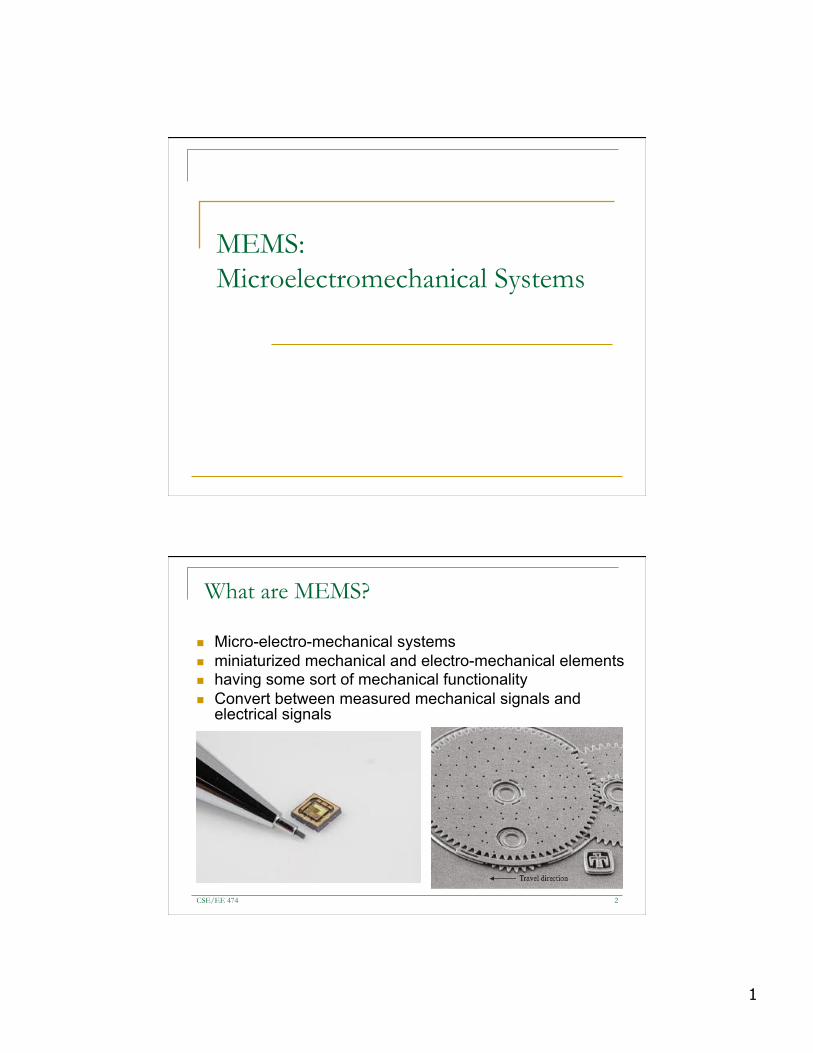
What are MEMS?
n Micro-electro-mechanical systems n miniaturized mechanical and electro-mechanical elements n having some sort of mechanical functionality n Convert between measured mechanical signals and
electrical signals
CSE/EE 474 2
2
Fundamentals of MEMS Devices
n Silicon q Already in use q Manipulatable conductivity q Allows for integration
n Thin-Film Materials q Silicon dioxide q Silicon nitride
CSE/EE 474 3
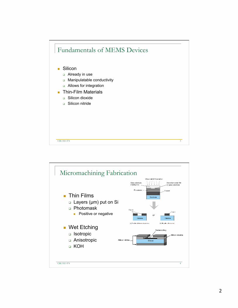
Micromachining Fabrication
n Thin Films q Layers (µm) put on Si q Photomask
n Positive or negative
n Wet Etching q Isotropic q Anisotropic q KOH
CSE/EE 474 4

3
Micromachining Fabrication II
n Dry Etching q RIE q DRIE
n Rate-Modified Etching q Cover with Boron q Wet etch with KOH
CSE/EE 474 5
Surface Micromachining
n Grow silicon dioxide n Apply photoresist n Expose and develop n Etch silicon dioxide n Remove photoresist n Deposit polysilicon n Remove silicon dioxide
CSE/EE 474 6

4
MEMS Packaging
n Purposes q Reduce EMI q Dissipate Heat q Minimize CTE q Deliver Required Power q Survive Environment
CSE/EE 474 7
Types of MEMS Packages
n Ceramic Packaging q Hermetic when sealed q High Young’s Modulus q Flip Chip or Wirebonding
n Plastic Packaging q Not Hermetic q Postmolding q Premolding
n Metal Packaging q Hermetic when sealed q Easy to assemble q Low Pin Count
CSE/EE 474 8

5
Typical MEMS Devices
n Sensors q Pressure Sensors q Accelerometers
n Actuators q Gyroscopes q High Aspect Ratio Electrostatic Resonators q Thermal Actuators q Magnetic Actuators q Comb-drives
CSE/EE 474 9
Typical MEMS Devices
n Sensors q Pressure Sensors q Accelerometers
n Actuators q Gyroscopes q High Aspect Ratio Electrostatic Resonators q Thermal Actuators q Magnetic Actuators q Comb-drives
CSE/EE 474 10

6
Accelerometers
n Applications: q Air bag crash sensors q Active suspension
systems q Antilock brake systems q Ride control systems q Smartphones
n Units of mV/g
CSE/EE 474 11
MEMS Accelerometer
Mass, Spring, Damper Model
CSE/EE 474 12

7
MEMS Accelerometer
CSE/EE 474 13
MEMS Accelerometer (cont’d)
CSE/EE 474 14
8
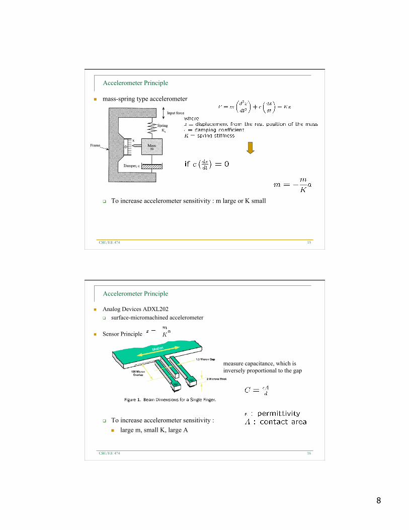
Accelerometer Principle
n mass-spring type accelerometer
q To increase accelerometer sensitivity : m large or K small
CSE/EE 474 15
Accelerometer Principle
n Analog Devices ADXL202 q surface-micromachined accelerometer
n Sensor Principle
q To increase accelerometer sensitivity : n large m, small K, large A
measure capacitance, which is inversely proportional to the gap
CSE/EE 474 16

9
ADXL 202 Dual Axis Accelerometers
n To increase the mass, common beam mass is used
x
y
x direction acceleration is detected here
spring
CSE/EE 474 17
MEMS Gyroscopes
n Typically Vibratory Gyroscopes q Utilize Coriolis Acceleration (“fictional force”) q Due to rotating reference frame
CSE/EE 474 18

10
Coriolis force
CSE/EE 474 19
Coriolis force
CSE/EE 474 20

11
Types of Vibratory Gyroscopes
Vibrating Beam, Vibrating Disk, Vibrating Shell
CSE/EE 474 21
Gyroscope
n Gyroscopic Precession q What will happen if there is rotation around the rotation axis
CSE/EE 474 22

12
Coriolis Acceleration
n Coriolis acceleration q A person moving northward toward the outer edge of a rotating platform
must increase the westward speed component (blue arrows) to maintain a northbound course. The acceleration required is the Coriolis acceleration.
CSE/EE 474 23
Coriolis Acceleration
n Constrained motion means force is applied
24
turning fork gyroscope
CSE/EE 474

13
Gyroscope using Coriolis effect
n Schematic of the gyro’s mechanical structure
n The displacement is proportional to the rotation speed
CSE/EE 474 25
Disc Resonating Gyro Basics
CSE/EE 474 26

14
Disc Resonating Gyro Basics
n Gyroscope is driven to resonate in-plane
n Electrodes sense deflection in outer ring sockets
n Electrodes actuate in inner ring sockets
n Circuits process the signal and feedback into the system
CSE/EE 474 27
Operation Principle of the DRG
CSE/EE 474 28

15
Coriolis Effect
n Coriolis acceleration (a) occurs if a resonating disc is pterturbed
n Depends on velocities on the disc è higher frequencies allow Coriolis acceleration to dominate centrifugal acceleration
n Coriolis acceleration is what the electrodes sense through change in capacitance
CSE/EE 474 29
How Does the DRG Work?
n DC Source creates an electrostatic force that moves the disc
n Proper control of these electrodes can put the system into resonance
n Similarly, the sensing electrodes use gap changes to gauge system changes
CSE/EE 474 30
16
One Ring or Many?
n One major advantage of this system is its large area
n Compared to a single ring gyro, has much more control over actuation and sensing
n Single rings require flexible support beams as well
CSE/EE 474 31
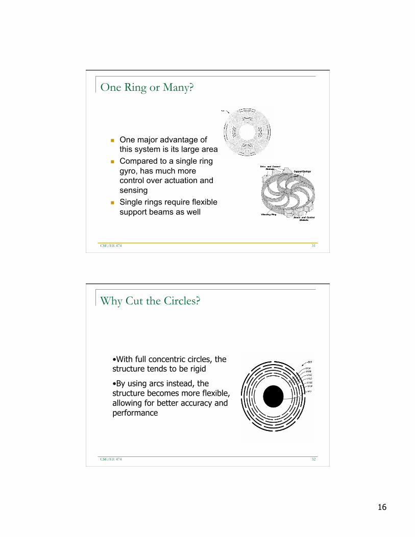
Why Cut the Circles?
• With full concentric circles, the structure tends to be rigid
• By using arcs instead, the structure becomes more flexible, allowing for better accuracy and performance
CSE/EE 474 32

17
CSE/EE 474 33
Invensense MPU-6050 6-axis gyroscope and accelerometer
4 x 4 x 1 mm
CSE/EE 474 34

18
MPU-6050
Supply voltage of 2.375V – 3.46V Current of 3.9mA Uses an I2C bus
Selectable gyroscope and accelerometer ranges
1MHz internal clock
CSE/EE 474 35
CSE/EE 474 36

19
Sample MPU-6050 data
n The accelerometer and gyroscope measurements are explained in the MPU-6050 datasheet in the GYRO_CONFIG and ACCEL_CONFIG register descriptions (sections 4.4 and 4.5 on pages 14 and 15).
n The scale of each depends on the sensitivity settings chosen q +/- 2, 4, 8, or 16g for the accelerometer q +/- 250, 500, 1000, or 2000 deg/sec for the gyroscope.
n The accelerometer produces data in units of acceleration (distance over time2)
n The gyroscope produces data in units of rotational velocity (rotation distance over time).
CSE/EE 474 37
Sample MPU-6050 data
n The output scale for any setting is [-32768, +32767] for each of the six axes. The default setting in our example is +/- 2g for the accel and +/- 250 deg/sec for the gyro.
n If the device is perfectly level and not moving, then: q X/Y accel axes should read 0 q Z accel axis should read 1g, which is +16384 at a sensitivity of 2g q X/Y/Z gyro axes should read 0
n In reality, the accel axes won't read exactly 0 since it is difficult to be perfectly level and there is some noise/error, and the gyros will also not read exactly 0 for the same reason (noise/error).
CSE/EE 474 38

20
MPU6050 is online... x-axis self test: acceleration trim within : 0.6% of factory value y-axis self test: acceleration trim within : 0.6% of factory value z-axis self test: acceleration trim within : 0.7% of factory value x-axis self test: gyration trim within : 0.2% of factory value y-axis self test: gyration trim within : -0.2% of factory value z-axis self test: gyration trim within : 0.3% of factory value MPU6050 initialized for active data mode.... X-acceleration: -3.30 mg Y-acceleration: 1.71 mg Z-acceleration: 1005.68 mg X-gyro rate: -1.9 degrees/sec Y-gyro rate: 0.3 degrees/sec Z-gyro rate: -0.3 degrees/sec Temperature is 13.31 degrees C X-acceleration: 14.40 mg Y-acceleration: 0.98 mg Z-acceleration: 1003.36 mg X-gyro rate: 0.4 degrees/sec Y-gyro rate: 0.1 degrees/sec Z-gyro rate: 0.0 degrees/sec Temperature is 23.27 degrees C
Sample MPU-6050 data
CSE/EE 474 39
CSE/EE 474 40