Memory management cheat sheet - WordPress.com · Memory management cheat sheet 2016 1Figures...
4
Memory management cheat sheet 2016 1 Figures borrowed from Memory management: algorithms and implementation in C/C++ . Bill Blunden @vhramosa – https://securitywithattitude.wordpress.com Real mode register setup Real mode address resolution process 16-bit flag register CS Segment address of code currently being executed. SS Segment address of stack. DS Data segment address. ES Extra segment address (usually data). FS Extra segment address (usually data). GS Extra segment address (usually data). segment + offset = real (physical) address Need to add 4 bits to segment address to produce a 20-bit address. Carry: used to indicate if an unsigned operation overflowed. Parity: low byte of result has even parity. Auxiliary: Set by most CPU instructions if the least significant (aka the low-order bits) of the destination operand contain an even number of 1's. Zero: set (1) if the result an operation is binary zero Sign: set (1) if MSB is 1 (sign) Trap: Permits single stepping of programs. Useful for debugging. Interrupt enable: when set, the processor recognizes external interrupts on the INTR pin. Direction: When set to 1, string operations process down from high addresses to low addresses. If cleared, string operations process up from low addresses to high addresses. Overflow: used to indicate if a signed operation overflowed.
Transcript of Memory management cheat sheet - WordPress.com · Memory management cheat sheet 2016 1Figures...
Memory management cheat sheet 2016
1 Figures borrowed from Memory management: algorithms and implementation in C/C++ . Bill Blunden @vhramosa – https://securitywithattitude.wordpress.com
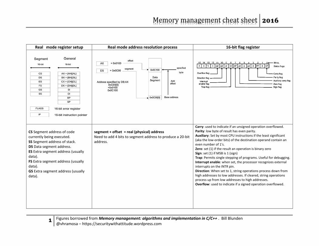
Real mode register setup Real mode address resolution process 16-bit flag register
CS Segment address of code currently being executed. SS Segment address of stack. DS Data segment address. ES Extra segment address (usually data). FS Extra segment address (usually data). GS Extra segment address (usually data).
segment + offset = real (physical) address Need to add 4 bits to segment address to produce a 20-bit address.
Carry: used to indicate if an unsigned operation overflowed. Parity: low byte of result has even parity. Auxiliary: Set by most CPU instructions if the least significant (aka the low-order bits) of the destination operand contain an even number of 1's. Zero: set (1) if the result an operation is binary zero Sign: set (1) if MSB is 1 (sign) Trap: Permits single stepping of programs. Useful for debugging. Interrupt enable: when set, the processor recognizes external interrupts on the INTR pin. Direction: When set to 1, string operations process down from high addresses to low addresses. If cleared, string operations process up from low addresses to high addresses. Overflow: used to indicate if a signed operation overflowed.
Memory management cheat sheet 2016
2 Figures borrowed from Memory management: algorithms and implementation in C/C++ . Bill Blunden @vhramosa – https://securitywithattitude.wordpress.com
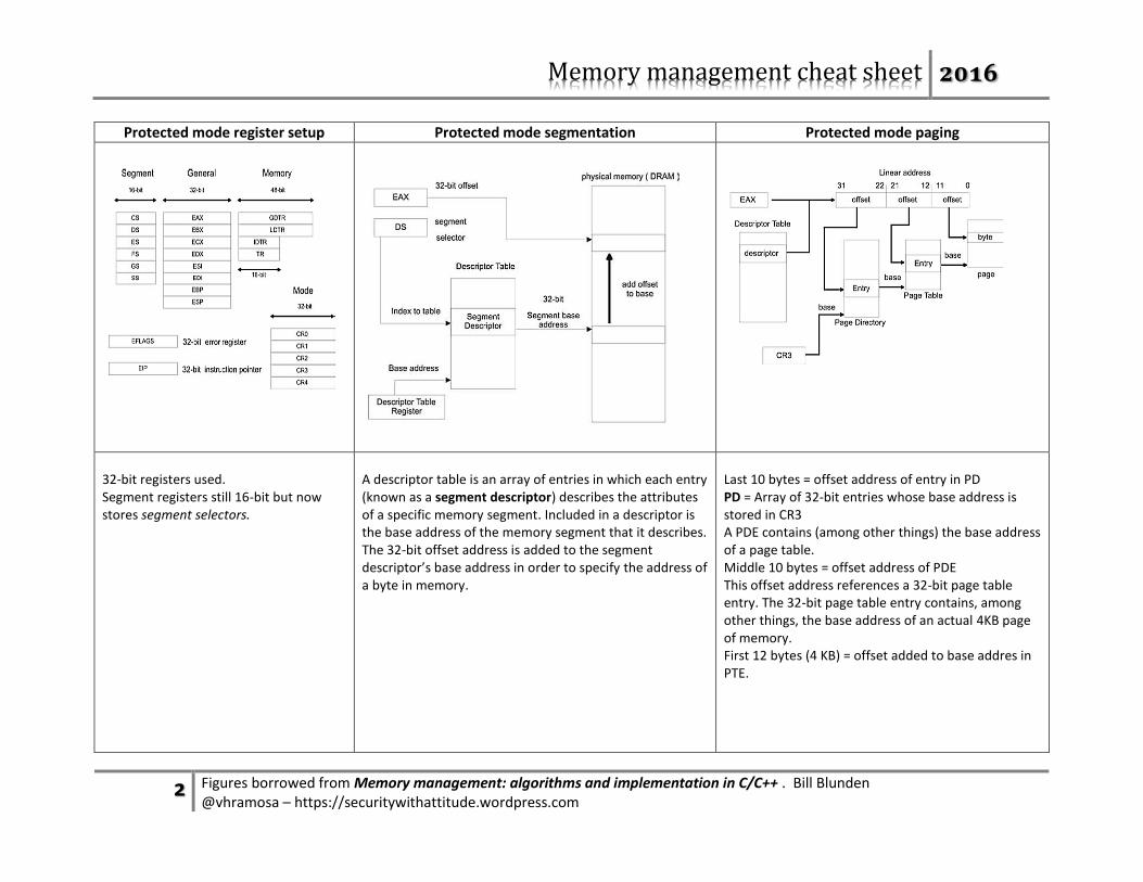
Protected mode register setup Protected mode segmentation Protected mode paging
32-bit registers used. Segment registers still 16-bit but now stores segment selectors.
A descriptor table is an array of entries in which each entry (known as a segment descriptor) describes the attributes of a specific memory segment. Included in a descriptor is the base address of the memory segment that it describes. The 32-bit offset address is added to the segment descriptor’s base address in order to specify the address of a byte in memory.
Last 10 bytes = offset address of entry in PD PD = Array of 32-bit entries whose base address is stored in CR3 A PDE contains (among other things) the base address of a page table. Middle 10 bytes = offset address of PDE This offset address references a 32-bit page table entry. The 32-bit page table entry contains, among other things, the base address of an actual 4KB page of memory. First 12 bytes (4 KB) = offset added to base addres in PTE.
Memory management cheat sheet 2016
3 Figures borrowed from Memory management: algorithms and implementation in C/C++ . Bill Blunden @vhramosa – https://securitywithattitude.wordpress.com
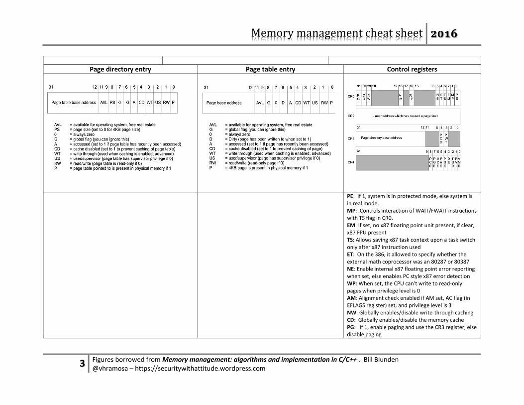
Page directory entry Page table entry Control registers
PE: If 1, system is in protected mode, else system is in real mode. MP: Controls interaction of WAIT/FWAIT instructions with TS flag in CR0. EM: If set, no x87 floating point unit present, if clear, x87 FPU present TS: Allows saving x87 task context upon a task switch only after x87 instruction used ET: On the 386, it allowed to specify whether the external math coprocessor was an 80287 or 80387 NE: Enable internal x87 floating point error reporting when set, else enables PC style x87 error detection WP: When set, the CPU can't write to read-only pages when privilege level is 0 AM: Alignment check enabled if AM set, AC flag (in EFLAGS register) set, and privilege level is 3 NW: Globally enables/disable write-through caching CD: Globally enables/disable the memory cache PG: If 1, enable paging and use the CR3 register, else disable paging
Memory management cheat sheet 2016
4 Figures borrowed from Memory management: algorithms and implementation in C/C++ . Bill Blunden @vhramosa – https://securitywithattitude.wordpress.com
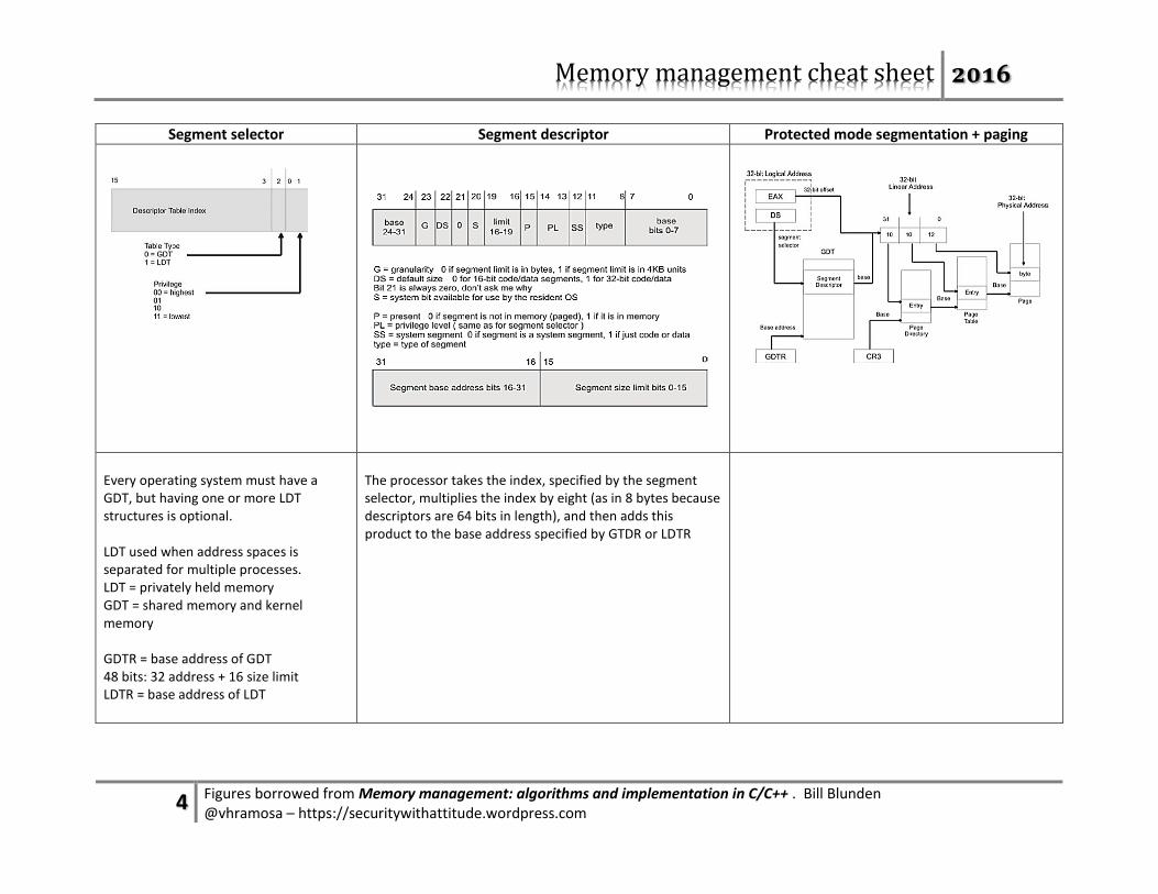
Segment selector Segment descriptor Protected mode segmentation + paging
Every operating system must have a GDT, but having one or more LDT structures is optional. LDT used when address spaces is separated for multiple processes. LDT = privately held memory GDT = shared memory and kernel memory GDTR = base address of GDT 48 bits: 32 address + 16 size limit LDTR = base address of LDT
The processor takes the index, specified by the segment selector, multiplies the index by eight (as in 8 bytes because descriptors are 64 bits in length), and then adds this product to the base address specified by GTDR or LDTR