MEMORY HiLOGGER - Test Equipment Depot · Introduction 1 Thank you for purchasing the HIOKI "Model...
32
MEMORY HiLOGGER Quick Start Manual 8423 November 2012 Revised edition 6 8423A983-06 12-11H Read first. Offers an introduction to the Memory HiLogger's basic measuring method for first time users. 99 Washington Street Melrose, MA 02176 Phone 781-665-1400 Toll Free 1-800-517-8431 Visit us at www.TestEquipmentDepot.com
-
Upload
nguyenquynh -
Category
Documents
-
view
217 -
download
3
Transcript of MEMORY HiLOGGER - Test Equipment Depot · Introduction 1 Thank you for purchasing the HIOKI "Model...

MEMORY HiLOGGER
Quick Start Manual
8423
November 2012 Revised edition 6 8423A983-06 12-11H
Read first.Offers an introduction to the MemoryHiLogger's basic measuring methodfor first time users.
99 Washington Street Melrose, MA 02176 Phone 781-665-1400Toll Free 1-800-517-8431
Visit us at www.TestEquipmentDepot.com
Contents
i
Contents
Introduction ________________________________ 1
Verifying Package Contents ___________________ 3
Names and Functions of Parts _________________ 4
Installing the Software________________________ 6Installing Logger Utility .................................................................7Installing the USB Driver ..............................................................8
Software Screen____________________________ 12
Setting Up the Instrument ____________________ 13
Taking Measurements _______________________ 18
Application Measurement Tips________________ 29

Introduction
1
Thank you for purchasing the HIOKI "Model 8423 Memory HiLogger." To obtainmaximum performance from the instrument, please read this manual first, andkeep it handy for future reference.
The following instruction manuals are included with the 8423 Memory HiLogger.Refer to them as they pertain to your usage of the instrument.
• Before reading this manual, fully read and understand "Safety Information"and "Chapter 3 Setting Up the Instrument" in the instruction manual, and thenstart taking measurements.
• Use an optional measurement unit for measurement. Carefully read theinstruction manual supplied with the measurement unit, and observe thesafety precautions.
RegisteredTrademarks
• Windows is a registered trademark of Microsoft Corporation in the UnitedStates and/or other countries.
• Pentium is a registered trademark of Intel Corporation.
Introduction
Manuals Contents
1Quick StartManual(this manual)
Read first.Offers an introduction to the 8423's basic measuringmethod for first time users.
2 Instruction Manual Contains explanation and instructions regarding theinstrument's operating method and functions.

Introduction
2
Safety SymbolsThe following symbols in this manual indicate the relative importance of cautionsand warnings.
Others
Mouse Operation
Notation
Indicates that incorrect operation presents a significanthazard that could result in serious injury or death to theuser.
Indicates that incorrect operation presents a possibility ofinjury to the user or damage to the instrument.
Indicates advisory items related to performance or correctoperation of the instrument.
Indicates quick references for operation and remedies fortroubleshooting.
* Indicates that descriptive information is provided below.
[ ] Menus, pages, setting items, dialogs, buttons in a dialog,and other names on the screen and the keys are indicatedin brackets.Unless otherwise specified, "Windows" represents Win-dows 2000, Windows XP, Windows Vista or Windows 7.Dialog box represents a Windows dialog box.
Click Press and quickly release the left button of the mouse.
Right-click Press and quickly release the right button of the mouse.
Double click Quickly click the left button of the mouse twice.
Drag While holding down the left button of the mouse, move themouse and then release the left button to deposit the cho-sen item in the desired position.
Activate Click on a window on the screen to activate that window.

Verifying Package Contents
3
When you receive the instrument, inspect it carefully to ensure that no damageoccurred during shipping. In particular, check the accessories, panel switches,and connectors. If damage is evident, or if it fails to operate according to thespecifications, contact your dealer or Hioki representative.
Verifying Package Contents
Model 8423 Memory HiLogger.................................................. 1
Please check to make sure that no items are missing from your package.
Quick Start Manual ...........................................1 Instruction Manual ............................................1
Logger Utility CD (data collection software)......1(The latest version can be downloaded from our web site.)
Model 9418-15 AC Adapter ..............................1
USB Cable ........................................................1
Connector Cover...............................................1
Ferrite Clamps ..................................................1
Connection Plate ..............................................1

Names and Functions of Parts
4
Names and Functions of Parts
CF card slot
Power switch
Front Panel
AC adapter connector
CF card access LED External control input terminals
Synchronization cable connectors
100BASE-TX connector
USB connector
DisplayKey operations(See the next page)
Names of parts Explanations
Display Displays setting values, measurement values, error messages, warningmessages, and other information.
CF card access LED
• When the cover is open:Off: The CF card can be ejected. Lit red: The CF card cannot be ejected because data is being written.
• When the cover is closed:Off: A CF card is not inserted or recording is not possible because theCF card cannot be recognized. Lit green: A CF card is inserted and recording is possible. Lit red: The CF card is being read or written.
CF card slot Allows for a CF card to be inserted for saving measurement data. Power switch Turns the power ON/OFF.AC adapter connector Allows for a 9418-15 AC Adapter to be connected. USB connector Allows for a USB cable to be connected. 100BASE-TX connector Allows for a 9642 LAN Cable to be connected.
Synchronization cable connector
Allows for connecting optional 9683 Connection Cable (for synchroniza-tion) when you want to perform synchronized measurement with multipleMemory HiLoggers.
External control input terminals
Allows for controlling the instrument by inputting a signal from an externaldevice.

Names and Functions of Parts
5
Key Operations
Keys Explanations
• The key lights during measurement. • Press the key once during standby to start measurement. • Press the key during measurement to input an event mark.
When the power is on:You can initialize the settings by turning the power on while pressing
and . See "13.3 Initializing Settings (System Reset)" in the Instruction Manual.
• Press the key twice in succession during measurement to stop mea-surement.
When the power is on:You can initialize the settings by turning the power on while pressing
. See "13.3 Initializing Settings (System Reset)" in the Instruction Manual.
• Switches the display content. • The key flashes while an error message or warning message is dis-
played. Press the key once to clear the display.• If the key is pressed for at least one second and then released while
measurement values are displayed during measurement, the displaychannels are fixed to those displayed the instant the key was released.Press the key for at least one second again to cancel fixing of the dis-play channels.
When the power is on:The instrument enters setting mode if you turn on the power while press-
ing . See "Chapter 10 Setting Method for Logger" in the Instruction Manual.
Installing the Software
6
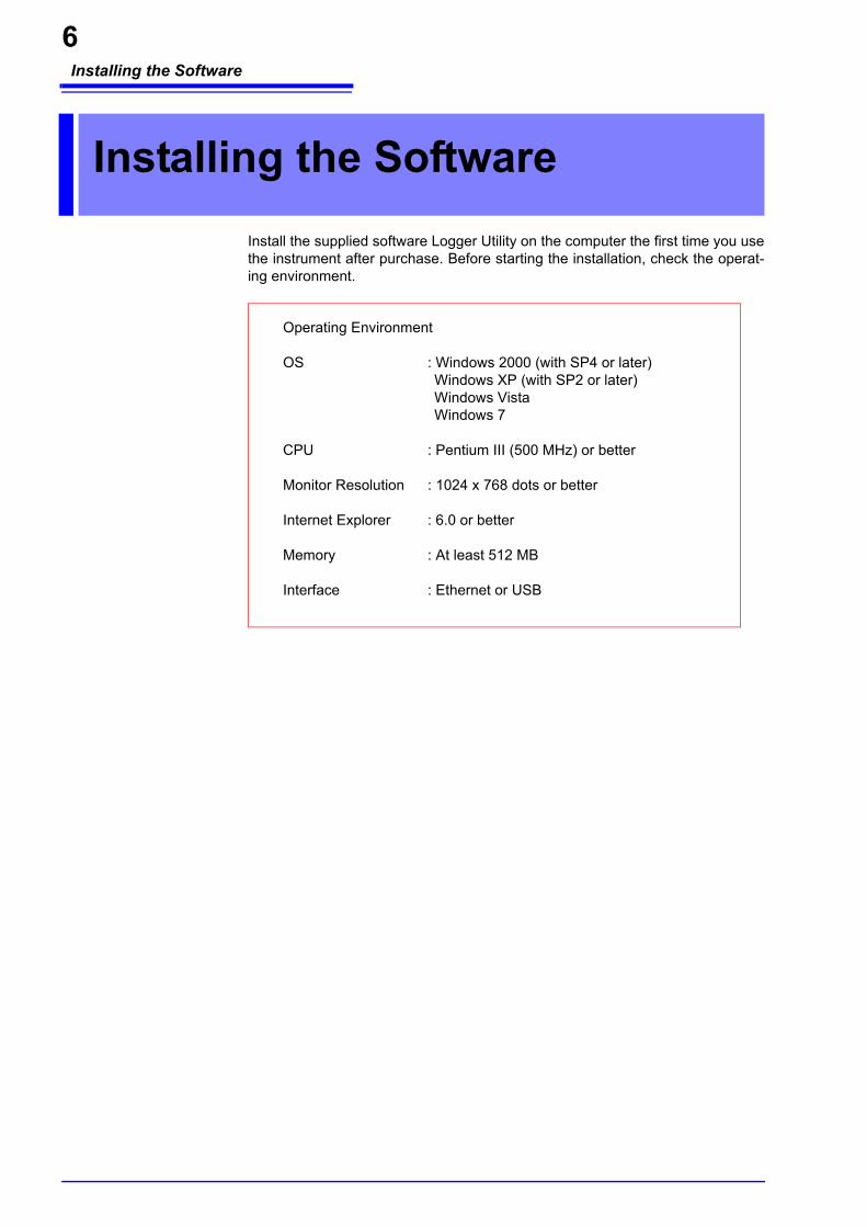
Install the supplied software Logger Utility on the computer the first time you usethe instrument after purchase. Before starting the installation, check the operat-ing environment.
Installing the Software
Operating Environment
OS : Windows 2000 (with SP4 or later) Windows XP (with SP2 or later)Windows VistaWindows 7
CPU : Pentium III (500 MHz) or better
Monitor Resolution : 1024 x 768 dots or better
Internet Explorer : 6.0 or better
Memory : At least 512 MB
Interface : Ethernet or USB

Installing the Software
7
Follow the procedure below to install Logger Utility. This explanation is for install-ing the software on Windows XP. The messages displayed may differ slightlydepending on the operating system you are using.
1. Start up Windows.Exit all running applications.
2. Insert the included CD into the computer's CD-ROM drive, theinstaller run automatically.If the installer do not start, execute “Setup.exe” from the CD-ROM drive.In Vista, Although the dialog which ask for installation permission of application,click [Allow].
3. Follow the on-screen instructions to install the software.
Installing Logger Utility
ImportantIf you are running software such as antivirus software, be sure to endthe software before you start the installation. The installation may notbe performed properly if antivirus software is running.
Click

Installing the Software
8
Install the USB driver before you use the instrument with a USB connection.
1. Install the driver.Run [SetupDriver32.msi] in the CD-R.If [Logger Utility] is already installed, run the CD from the following loca-tion.[c:\Program Files\HIOKI\LoggerUtility\Driver\SetupDriver32.msi]
If you are using the WindowsVista/7 64bit version:[c:\Program Files(x86)\HIOKI\LoggerUtility\Driver\SetupDriver64.msi]Run [SetupDriver64.msi] in the CD-R.If [Logger Utility] is already installed, run the CD from the following loca-tion.[c:\Program Files\HIOKI\LoggerUtility\Driver\SetupDriver64.msi]
2. Click [Next].
Installing the USB Driver
Depending on the environment, the dialog box may take some time to appear soplease wait till it does so.
Click

Installing the Software
9
3. Check [Everyone] and click [Next].
4. Click [Next] to start installing.
For WindowsXPDuring the installation, a message saying that the software has not passedWindows Logo testing will appear a few times, click [Continue Anyway]to continue installing.
For WindowsVista/7When a dialog box requesting your permission to continue the programappears, click [Continue].Sometimes another dialog box requesting your permission to install thesoftware may appear. When it does, check “Always trust software from[HIOKI E.E. CORPORATION] and click [Install] to continue.
(2) Click
(1) Click
Click

Installing the Software
10
5. When installation is completed and the dialog box appears, click [Close] toexit.
6. Connect the instrument and computer with the USB cable provided.
For Windows2000/Vista/7The HiLogger is automatically recognized, and preparations to use thedevice are complete.
For WindowsXPA [Found New Hardware Wizard] dialog box will appear and the new hard-ware detection wizard will begin.
7. Check [No, not this time] and click [Next].
8. Check [Install the software automatically (Recommended)] and click[Next]. Please wait while the driver is being installed.
Click
Do not plug in or unplug the USB cable while the instrument is operating.
(2) Click
(1) Click

Installing the Software
11
9. Click [Continue Anyway].A message saying that the software has not passed Windows Logo testingwill appear a few times, click [Continue Anyway] to continue installing.
10. When installation is completed and the dialog box appears, click [Finish]to exit.
Click

Software Screen
12
This chapter describes the screen configuration, part names, and functions ofthe supplied software Logger Utility. Please see the Instruction Manual.
Software Screen
Settings ScreenAllows for setting measure-ment conditions.
Waveform Display AreaDisplays measurement data as waveforms.
List Display AreaDisplays measurement data as numerical values.
Display Settings WindowsClick the tabs on the right side to display setting items. The windows allow for con-figuring the advanced set-tings of the waveform display area, analyzing data, etc.
Status BarDisplays the status of the main screen.
Measurement ConditionDisplays measurement condition as "Measuring", "Stop", “Waiting for TRIG”, etc.
Saves and loads measurement data and setting data, print wave-forms, etc.
Menu Bar Tool Button
Displays the settings screen, starts and stops mea-surement, etc.

Setting Up the Instrument
13
Follow the procedure below to prepare the measurement instrument beforebeginning measurement.
Required tools: Phillips screwdriver ................... 1
1. Attach the unit to the 8423 Memory HiLogger. To attach multipleunits.
2. Secure the unit in place with the connection fittings at the top andbottom of the unit. Use the Phillips screwdriver to tighten the screws to no more than 0.6 Nm.
3. Attach the supplied connector cover to the unit on the very left sidewhen looking from the front. Insert the protruding part of the connector cover into the connector opening ofthe unit, close the cover, and then secure it in place with the screw. Tighten thescrew to no more than 0.6 Nm.
Setting Up the Instrument
Align
Left side of Memory HiLogger
Right side of unit
PressPress
Maximum of eight units
(2) Press and turn
Top of 8423 Memory HiLogger
(1) Loosen the screw
(3) Tighten the screw
ConnectionFittings
Connector cover

Setting Up the Instrument
14
4. Pull down the levers on the rear of the instrument and unit, andhook the connection plate on to the hooks at the top of the DIN railmounting groove.
5. Push up the levers until they click into place.
DIN Rail Mounting Groove
Lever
• To avoid electric shock accident, before removing or replacing a unit, confirmthat the instrument is turned off and that the cables are disconnected.
• If the units are not securely attached with the connection fittings, the specifica-tions may not be satisfied, resulting in a malfunction.
• Failure to fasten the connectors properly may result is sub-specification perfor-mance or damage to the equipment
• Be sure to attach the supplied connector cover to the unit at the very end.
Up to eight units can be connected to the instrument. If nine or more units areconnected, measurement will not be possible.

Setting Up the Instrument
15
6. Loosen the screw at the bottom of the cover with the Phillips screw-driver and lift up the cover.
7. Loosen the screws of the terminal block, connect the input cable,and then tighten the screws. The connection method differs depending on the measurement object. See "3.2 Connecting a Cable to the Terminal Block" in the Instruction Manual.
8. Reattach the cover, and tighten the screw. Tighten the screw to no more than 0.6 Nm.
Lift up
Phillips screwdriver
+ -
The 8948 Voltage/Temp UnitWhen a thermocouple cable is connected
Example: + -
CH1
CH15
• In order to prevent electric shock and short-circuit accidents, shut off the powerto the line to be measured before connecting the input cable.
• To avoid electrical accidents, confirm that all connections are secure. Theincreased resistance of loose connections can lead to overheating and fire.
• Channels are isolated by semiconductor relays. Never apply a voltage inexcess of the specifications between channels as doing so could damage thesemiconductor relays by causing them to short out. Exercise particular careconcerning surge protection against lightning and other threats. If the instru-ment yields erroneous measured values, have it inspected.
Be sure to pull out an input cable after you loosen the screws of the terminalblock. The input cable will be damaged if the screws are not loosened andexcessive force is used to pull out the input cable.

Setting Up the Instrument
16
9. Connect the connector of the AC adapter to the connector of theinstrument, and insert the plug into a power outlet with a ground.
10. Connect the instrument to a computer with a USB cable. A USB cable is used in this example, but you can also use a LAN cable in thesame way.
HookInsert the plug
USB cable
USB connector
• Turn the instrument off before connecting the AC adapter to the instrument andto AC power.
• Use only the supplied Model 9418-15 AC Adapter. AC adapter input voltagerange is 100 to 240 VAC (with ±10% stability) at 50/60 Hz. To avoid electricalhazards and damage to the instrument, do not apply voltage outside of thisrange.
• To avoid electrical accidents and to maintain the safety specifications of thisinstrument, connect the power cord provided only to a 3-contact (two-conduc-tor + ground) outlet.
• To avoid damaging the power cord, grasp the plug, not the cord, when unplug-ging it from the power outlet.
• To avoid a malfunction, do not connect or disconnect the USB cable or LANcable during operation.
• To avoid a malfunction, do not connect or disconnect the USB cable or LANcable during operation.

Setting Up the Instrument
17
11. Insert the CF card.The measurement data is sent to the computer, but you can also save the datato the CF card.
12. Press the power switch to turn the power on ( ).The model name and version appear on the screen, and then the instrumententers the standby state (clock displayed).
Preparations for the measuring instrument are complete with the above.
CF card
Cover
Eject button
Format a CF card on a computer the first time you use it or before you beginmeasurement. If the CF card has been used for another purpose, saving maytake a while or the file information may be damaged. Formatting will preventthese problems from occurring. See "3.6.1 Formatting a CF Card" in the Instruction Manual.
To avoid an electric shock or short-circuit accident, confirm the following itemsbefore turning on the power. • When using the AC adapter, make sure the power supply is a rated supply
voltage (100 to 240 VAC) and rated supply frequency (50/60 Hz) of the instru-ment. (Voltage fluctuations of ± 10% from the rated supply voltage are takeninto account.)
• Makes sure the instrument is installed properly.
To avoid damaging the instrument, make sure the input cables are connectedproperly.

Taking Measurements
18
This section uses a simple measurement example to present the flow of mea-surement to first-time users of the Memory HiLogger.
Connect an 8948 Voltage/Temp Unit to the 8423 Memory HiLogger, and mea-sure the temperature at 15 locations in the office for a period of 8 hours. Set andsend the measurement conditions with the application software on the computer.
Rec. time 8 hours
Rec. interval 1 s
Comm. cable USB cable
Saved media PC and CF card
Unit Model 8948 Voltage/Temp Unit
Required tools Model 8423 Memory HiLogger × 1, Model 8948 Voltage/Temp Unit × 1, Model9418-15 AC Adapter × 1, USB cable × 1, PC × 1, Thermocouple (K) × 15,Model 9726 PC Card 128M × 1
Taking Measurements
Measurement Example: Determining the Temperature Distribution in an Office
USB cable (or LAN cable)
Office
Thermocouple(15 locations)
Set the measurement conditions with the application software
PCModel 8423 and 8948
Measurement conditions
Measurement data

Taking Measurements
19
Follow the procedure below to set the measurement conditions.
Connection Settings1. From the Start Menu of Windows, click [All Programs] - [HIOKI] -
[Logger Utility] - [Logger Utility].
2. Click the button in the main screen to display the connec-
tion settings page of the settings screen.
Setting Measurement Conditions
(1) Click
(2) Click

Taking Measurements
20
3. Select the search object from USB and LAN.For this example, select "USB" here.
4. Click the [Search] button, and then The loggers connected to thecomputer appear.
5. Select the logger to register from the list. 6. Click the [Add from Found Loggers] button to register the selected
logger.
7. Click the [Set Clock] button to display the [Synchronize Clock] dia-log box.
8. Click the [Set Clock] button to set the time of each logger to that ofthe computer.
: Loggers connected by LAN
: Loggers connected by USB
: Loggers that can be registered
(2) Click
(1) Click
(3) A searched logger appears here
(2) Click
(1) Click
The 8423's serial number is displayed.
(3) A registered logger appears here
Click
This indicates the time of the comput-er.
Click
This button allows you to check the current time of the logger.

Taking Measurements
21
Unit Configuration
1. Confirm that the unit configuration shown on the unit configurationpage matches the actual content.
2. Set the digital filter.
Selectable Items Explanations
OFF The filter is not used.
50Hz Select this to use at an operating power frequency of 50 Hz.
60Hz Select this to use at an operating power frequency of 60 Hz.
(1) Click
(2) Select

Taking Measurements
22
Measurement Settings
1. Click [Normal Sampling] on the measurement settings page.
2. Set the recording interval (high-speed). For this example, select "1s" here.
3. Set the location to save the measurement data file.
4. Set any comment.
5. Set the recording period. For this example, set “8 hours.” Set continuous recording and repeat recordingto “OFF.”
Selectable Intervals
10, 20, 50, 100, 200, 500 ms, 1, 2, 5, 10, 20, 30 s, 1, 2, 5, 10, 20, 30 m, 1 h
(3) Select
(2) Click
(1) Click

Taking Measurements
23
Channel Settings
1. Select the channel for measurement on the measurement settingspage of the channel settings. Each click of the button toggles measurement ON and OFF.
2. Set the input type and range to match the measurement object. For this example, select “Thermocouple” and “100°Cf.s.”See "5.4.1 Setting Measurement Conditions" in the Instruction Manual.
3. If you want to copy the setting information from channel 1 to chan-nels 2 to 15, select [Copy] and then click the [Execute] button.
(1) Click
(2) Click
(3) Select
: Measurement ON
Narrowing down of display channels
Copy the channel set-ting information to an-other channel.
(4) Click
(1) Select
(2) Click

Taking Measurements
24
4. Select the parameters to copy and the copy destination. For this example, select all the parameters.
5. Click [Copy] to copy the setting information. The settings of channels 1 to 15 become the same.
Selectable Items Explanations
Select All Select all the parameters to copy or copy destinations.
Unselect Clear the selection for all the parameters to copy or copy destinations.
Reverse Reverse the selection for the parameters to copy or copy destinations.
(3) Click
(1) Select
(2) Select

Taking Measurements
25
CF Card Save Settings
This section describes setting the method for saving data to a CF (compactflash) card inserted in the logger.
1. Click the icon of the logger you want to change the settings of onthe environment settings page. The background color of the selected icon turns red.
2. Select the auto save method to [Binary (real time)]. Use the mouse to select the desired setting from the list.
3. Enter the file name.
4. Select the real-time save mode to [File Full].Use the mouse to select the desired setting from the list.
5. Click the [Finish] button.
Setting of the measurement conditions is finished.
Selectable Items Explanations
OFF Do not save measurement data to the CF card inserted in the logger.
Binary (real time)
Save measurement data in binary format to the CF card inserted in the logger, while measuring.
(3) Select
(1) Click
(2) Click
(4) Click
Selectable Items Explanations
File Full Ends saving when there is no longer much available space on the CF card. However, measurement continues.
Delete and Save
When the amount of available space of the CF card reaches a certain level during measurement, the oldest file in the directory currently being recorded to is deleted and the new data is saved. If a file was unable to be deleted, the same operation as for [File Full] is per-formed.

Taking Measurements
26
Start measurement. The measurement data is sent to the computer in real time.The same data is also saved in the CF card.
1. Click the button in the main screen of Logger Utility to start
measurement.
2. Measurement continues for 8 hours and then stops automatically.
When you want to stop the measurement part way through, click the
button in the main window.
Starting and Ending Measurement

Taking Measurements
27
Why is a waveform not displayed?
The measurement waveform may have gone out of the display range. Change the dis-play upper limit and display lower limit settings on the [Channel] tab of the display set-tings window to match the measurement values. See "7.1 Changing the Waveform Display Range" in the Instruction Manual.
How do I check the measurement value at any point of a waveform?
Click the tool button on the main screen to display cursors A and B. You can confirmthe measurement value of a specific position of a cursor on the [Cursor] tab of the dis-play settings window. See "7.2 Checking Cursor Values" in the Instruction Manual.
How do I add graduations (scale) to the graph?
On the [Display Setting] tab in the display settings window, set gauge display to ON. See "7.3 Changing Display Settings" in the Instruction Manual.
How do I split the waveform display area into two?
On the [Display Setting] tab in the display settings window, set split screen to ON. See "7.3 Changing Display Settings" in the Instruction Manual.
How do I add a mark to a waveform?
Click the tool button on the main screen to display an event mark. You can then click onthe waveform to add an event mark. See "7.5 Event Mark Function" in the Instruction Manual.

Taking Measurements
28
To ensure measurement is performed safely, observe the following precautions.
*1 Between each of the input channels 1 to 5 and the logger main unit, betweeneach of the input channels 6 to 10 and the logger main unit, between each ofthe input channels 11 to 15 and the logger main unit, and between each unit
*2 Between each of the input channels 1 to 5 and each of the input channels 6 to10, between each of the input channels 6 to 10 and each of the input chan-nels 11 to 15, and between each of the input channels 1 to 5 and each of theinput channels 11 to 15 (GND is common for each of channels 1 to 5, chan-nels 6 to 10, and channels 11 to 15)
• The maximum input voltage, maximum rated voltage to earth, and maximumrated voltage between channels for the input/output terminals of each unit andthe external control input terminals of the 8423 Memory HiLogger main unit areas shown in the table below. To avoid an electric shock accident or damage tothe instrument, do not input the corresponding voltages or above.
• Channels are isolated by semiconductor relays. Never apply a voltage inexcess of the specifications between channels as doing so could damage thesemiconductor relays by causing them to short out. Exercise particular careconcerning surge protection against lightning and other threats. If the instru-ment yields erroneous measured values, have it inspected.
• Do not input a voltage that exceeds the measurement range of each range.Doing so will damage the unit.
• Do not directly input a voltage into the output terminal of the 8997 Alarm Unit.Doing so will damage the unit.
• The GND of the external control input terminals and the GND of the MemoryHiLogger main unit are not commonly insulated. To avoid damaging the instru-ment, make sure wiring is done in such a manner that no potential differencecan result between the GND of the external control input terminals and theGND of the equipment or device to be connected.
Input/Output Terminals Maximum Input Voltage
Maximum Rated Voltage to Earth
Maximum Rated Voltage between Channels
Model 8948 Input terminals 100 VDC 600 V AC/DC 200 VDC
Model 8949 Input terminals 60 VDC 600 V AC/DC 120 VDC
Model 8996 Input terminals 50 V DC 600 V AC/DC*1 33 Vrmsor 70 VDC*2
Model 8997 Output terminals -- 600 V AC/DC 33 Vrms
or 70 VDC
External Control Input Terminals
SMPL / TRIG
-5 to 10 VDC Not insulated --START
STOP
Model 8423 Unit
GND
Maximum Input Voltage Maximum
Rated Voltage to Earth
+
-
CH n
CH m
Maximum Rated Voltage between Channels
n m, n, m = 1 to 15
Unit

Application Measurement Tips
29
• Dividing the measurement data into sheetsIf you divide the channels into individual sheets, the target waveforms becomeeasy to view.See "5.4.4 Assigning Channels to Sheets" in the Instruction Manual.
• Outputting an alarm when a certain value is exceededIf you use the 8997 Alarm Unit, an error signal can be detected.See "5.6 Setting the Alarm Function" in the Instruction Manual.
• Setting sampling for each unitYou can use different sampling to measure signals with abrupt changes andsignals with gradual changes.See "5.3.1 Setting Function and Recording Interval" in the Instruction Manual.
• Measuring of 15 or more channelsA maximum of eight units can be connected to one 8423 Memory HiLogger toenable the measurement of up to 120 channels. Furthermore, the synchro-nous operation of five Memory HiLoggers facilitates the synchronized mea-surement of 600 channels.See "5.1.3 Settings for Synchronized Measurement" in the Instruction Manual.
• Printing waveformsThe displayed waveforms can be printed with the printer connected to thecomputer.See "Chapter 9 Printing" in the Instruction Manual.
• Calculating Measured DataThe measured data is calculated with preset arithmetic expression to displaythe waveform. Four arithmetic operations (+, -, *, /) are applicable to measure-ment channels and arithmetic channels. See "5.4.2 Waveform CalculationSettings " on the detailed Instruction Manual.
Application Measurement Tips

Test Equipment Depot - 800.517.8431 - 99 Washington Street Melrose, MA 02176
TestEquipmentDepot.com