MEMORY HiLOGGER 8420/8421/8422-51 - HIOKI · MEMORY HiLOGGER 8420-51,8421-51,8422-51 As demand for...
8
MEMORY HiLOGGER 8420-51 ,8421 -51 ,8422 -51 As demand for multi-channel temperature recording for environmental protection, energy conservation and HACCP activities increase steadily, portability to enable measurement everywhere and at all times, and communications support for connect- ing to IT (information technology) networks are becoming indispensable capabilities for measurement instruments. Furthermore, at measurement sites, accurate measure- ments are required in severe conditions such as the presence of different electrical po- tentials, hum noise from commercial power lines, and switching noise from inverters. In response to these requirements, we have developed the new models with enhanced noise immunity from that of the former models. Internal memory capacity is greatly increased – four times that of previous models! New multi-channel loggers with enhanced noise immunity Data Loggers
Transcript of MEMORY HiLOGGER 8420/8421/8422-51 - HIOKI · MEMORY HiLOGGER 8420-51,8421-51,8422-51 As demand for...

MEMORY HiLOGGER 8420-51,8421-51,8422-51
As demand for multi-channel temperature recording for environmental protection, energy conservation and HACCP activities increase steadily, portability to enable measurement everywhere and at all times, and communications support for connect-ing to IT (information technology) networks are becoming indispensable capabilities for measurement instruments. Furthermore, at measurement sites, accurate measure-ments are required in severe conditions such as the presence of different electrical po-tentials, hum noise from commercial power lines, and switching noise from inverters. In response to these requirements, we have developed the new models with enhanced noise immunity from that of the former models.
Internal memory capacity is greatly increased – four times that of previous models!
New multi-channel loggers with enhanced noise immunity
Data Loggers
2
External Trigger Terminals
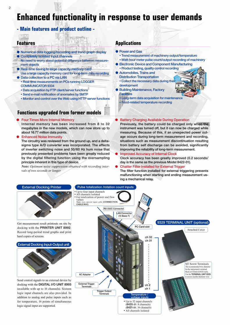
●Numerical data logging/recording and trend graph display●Completely isolated input channels No need to worry about potential difference between measure-
ment objects●Real-time saving to large capacity memory card Use a large capacity memory card for long-term data recording●Data collection to a PC via LAN • Real-time measurements on PCs running LOGGER
COMMUNICATOR 9334 • Data acquisition by FTP client/server functions • Send e-mail notification of anomalies by SMTP • Monitor and control over the Web using HTTP server functions
Temperature /voltage inputs
• Up to 32 input channels (8420-51: 8 channels) (8421-51: 16 channels)• All channels isolated
Get measurement result printouts on site by docking with the PRINTER UNIT 8992. Record long-period trend graphs and print hard copies of screens.
Send control signals to an external device by docking with the DIGITAL I/O UNIT 8993 (available with up to 16 channels). Sixteen logic input channels are also provided. In addition to analog and pulse inputs such as for temperature, 16 points of simultaneous logic signal input are supported.
ApplicationsFeatures
ch 32ch 31
ch 2ch 1
PC Card slot
LAN Connector(10 Base-T)
AC Adapter
RS-232C Connector
9329 TERMINAL UNIT (optional)
Attached Cover
M3 Screw TerminalsThe recommended wire diameter for the instrument’s terminal block is 0.32mm (0.0126 inch). Use the TERMINAL UNIT 9329 to secure smaller-diameter wire.
Pulse totalization /rotation count inputsExternal Docking Printer
External Docking Input-Output unit
Enhanced functionality in response to user demands- Main features and product outline -
● Four Times More Internal Memory Internal memory has been increased from 8 to 32
megabytes in the new models, which can now store up to about 16.77 million data points.
● Enhanced Noise Immunity The circuitry was reviewed from the ground up, and a delta-
sigma type A/D converter was incorporated. The effects of inverter switching noise and 50/60 Hz hum noise that previously presented problems have been greatly reduced by the digital filtering function using the oversampling principle inherent in this type of device.
Note: Optimum noise suppression obtained with recording inter-vals of two seconds or longer
● Battery Charging Available During Operation Previously, the battery could be charged only when the
instrument was turned off, but it can now be charged while measuring. Because of this, if an unexpected power out-age occurs during long-term measurement and recording, situations such as measurement discontinuation resulting from battery self discharge can be avoided, significantly improving the reliability of long-term measurement.
● Improved Accuracy of Internal Clock Clock accuracy has been greatly improved (0.2 seconds/
day is the same as the previous Model 8422-01).● Chatter Filter Installed for External Trigger The filter function installed for external triggering prevents
malfunctioning when starting and ending measurement us-ing a mechanical relay.
Functions upgraded from former models
• Up to four input channels• All channels isolated• For totalization of power and flow
values Note: uses special input cable (CONNECTION
CABLE 9641)
Trigger OutputTerminals
●Power and Gas • Trend measurement of machinery output/temperature • Watt-hour meter pulse count/output recording of machinery●Electronic Device and Component Manufacturing • Product testing, quality control recording●Automobiles, Trains and Distribution Transportation • Collect the necessary data during their development ●Building Maintenance, Factory Facilities • Long-term data acquisition for maintenance • Food-related temperature recording

3
Universal isolated temperature, voltage and pulse inputs, Universal measurement inputs, voltage, temperature (thermocouple and Pt inputs*1) and humidity*1,2 can be selected for each channel. In addition, four input channels are provided for measuring pulse inputs (totalization/rotation count) simultaneously with voltage, temperature and humidity. In addition to channel-to-channel input isolat ion, the PC connect ion inter face is completely isolated from the measurement terminals. Shock hazard is minimized even when thermocouples and voltage inputs are measured at the same time. (Maximum rated voltage above ground is 60 V DC.)*1 Pt and humidity measurement inputs are supported only by the 8420-51 and
8421-51.*2 Requires the HUMIDITY SENSOR 9653 (both optional).
Universal isolated temperature, voltage and pulse inputs
Measurement data can be automatically saved to a PC Card. Binary (real-time) and text (post-measurement) formats can be selected. High-capacity Flash ATA cards up to 1GB can be used for continuous long-term recording. Choose binary in normal use.This recording method is linked to writing measurements in real time. The supplied Wv Wave Viewer software can convert the data into text format on a PC.
Real-Time Save to High-Capacity Memory Card
Scroll through the displayed graph while saving measurements in real time to PC Card to verify earlier measurements. You can also read the values at the movable cursors.
Color LCD displays waveforms and numerical values simultaneously, and allows viewing earlier data while measuring
Real-Time Storage Recording Times with 64 MB Card (approximate times)Note: Recording times are calculated values, and cannot be guaranteed. For calculations, one year = 365 days. Calculated
values resulting in extremely long periods are omitted. "H" Exceeds 365 days.
Standard Measurement Screen(Measured values appear numerically at the left, and plotted as a graph at the right together with the measured values at the cursors.)
Display of Earlier Waveforms(The green bar at the bottom indicates the relative location of the current display in internal memory.)
Display of Current Measurements(The green bar at the bottom indicates the relative location of the current display in internal memory.)
All input channels are quickly scanned, measured and stored within 100 ms (200 ms or more with channels 17 to 32 in Model 8422-51, and within about 5 seconds for mixed humidity measurements). As stand-alone instruments, Model 8420-51 provides 4 pulse input channels, plus 8 temperature/voltage channels, Model 8421-51 provides 4 pulse input channels, plus 16 temperature/voltage channels, and Model 8422-51 provides 4 pulse input channels, plus 32 temperature/voltage channels. The 32MB of internal memory records about 16.77 million data points.
Sample multiple channels at high speeds
Temperature/Analog, all inputs isolated- Measurement Functions -
What happens if a power failure occurs while measuring ?We recommend using the real-time saving function of the MEMORY HiLOGGERs 8420-51, 8421-51 and
8422-51 with a PC Card. This exclusive technology has been developed to preserve data as reliably as possible even in the event of a power failure by incorporating PC card technology with the know-how built into the MEMORY HiCORDER series recording instruments. When recording only to internal memory without using a card, stored data is retained for about ten minutes in the event of a power failure.
Measurement parameters Ranges Range of Measurements Finest Resolution
Voltage
100mV f.s. -100mV to +100mV 5μV1V f.s. -1V to +1V 50μV10V f.s. -10V to +10V 500μV100V f.s. -60V to +60V 5mV1 − 5V f.s. 1V to 5V 500μV
TemperatureThermocouples: K, E, J, T, N, W (WRe5-26), R, S, B
100°C f.s. -100°C to 100°C 0.01°C500°C f.s. -200°C to 500°C 0.1°C2000°C f.s. -200°C to 2000°C 0.5°C
Pulse Accumulation
50,000c f.s. 0 to 50,000 counts 1 count500,000c f.s. 0 to 500,000 counts 10 counts5Mc f.s. 0 to 5M counts 100 counts100Mc f.s. 0 to 100M counts 2,000 counts2,500Mc f.s. 0 to 2,500M counts 50,000 counts
Rotation 5,000/n (r/s) f.s.*1 0 to 5,000/n (r/s)*1 1/n (r/s)*1
Humidity 100%rh f.s. 5.0 to 95.0%rh 0.1%rh *1 n = pulses per rotation (1 to 1,000)
Recording intervals
128 MB(using 1 channel)
128 MB(using 4 channels)
128 MB(using 8 channels)
128 MB(using 16 channels)
128 MB(using 32 channels)
100ms 72 days 18 days 9 days 4 days, 12 hours - NA -200ms 144 days 36 days 18 days 9 days 4 days, 12 hours500ms 360 days 90 days 45 days 22 days, 12 hours 11 days, 6 hours
1s 1 year, 355 days 180 days 90 days 45 days 22 days, 12 hours2s 3 year, 345 days 360 days 180 days 90 days 45 days5s 9 years, 315 days 2 years, 170 days 1 year, 85 days 225 days 112 days, 12 hours10s "H" 4 years, 340 days 2 years, 170 days 1 year, 85 days 225 days20s "H" 9 years, 315 days 4 years, 340 days 2 years, 170 days 1 year, 85 days30s "H" "H" 7 years, 145 days 3 years, 255 days 2 years, 170 days
1min "H" "H" "H" 7 years, 145 days 3 years, 255 days2min "H" "H" "H" "H" 7 years, 145 days
5min to 1hour "H" "H" "H" "H" "H"
4
The following PC measurements and various web server functions can be employed with a LAN or PPP connection (by connecting the RS-232C connector through a modem to a telephone circuit or cellular phone).
LAN Connectivity Supported by PPP Connection to a Telephone Circuit- Communication Functions -
• When communicating with a PC using FTP, acquired data is transferred only in file units.
• The 9334 software with a LAN connection supports quick response times as short as 100 ms.
• User-created PC commands necessary to use a direct RS-232C connection. A direct RS-232C connection allows near real-time measurement data to be obtained with response times of as little as about a second.
Remote measurements by HTTP server operation
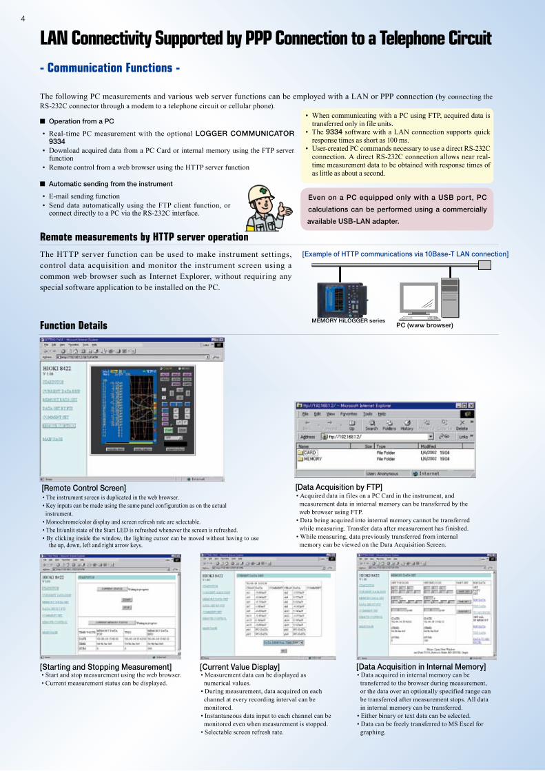
The HTTP server function can be used to make instrument settings, control data acquisition and monitor the instrument screen using a common web browser such as Internet Explorer, without requiring any special software application to be installed on the PC.
[Example of HTTP communications via 10Base-T LAN connection]
PC (www browser)
• The instrument screen is duplicated in the web browser.• Key inputs can be made using the same panel configuration as on the actual instrument.• Monochrome/color display and screen refresh rate are selectable.• The lit/unlit state of the Start LED is refreshed whenever the screen is refreshed.• By clicking inside the window, the lighting cursor can be moved without having to use
the up, down, left and right arrow keys.
[Remote Control Screen]
• Start and stop measurement using the web browser.• Current measurement status can be displayed.
[Starting and Stopping Measurement]• Measurement data can be displayed as numerical values.• During measurement, data acquired on each channel at every recording interval can be monitored.• Instantaneous data input to each channel can be monitored even when measurement is stopped.• Selectable screen refresh rate.
[Current Value Display]• Data acquired in internal memory can be transferred to the browser during measurement, or the data over an optionally specified range can be transferred after measurement stops. All data in internal memory can be transferred.• Either binary or text data can be selected.• Data can be freely transferred to MS Excel for graphing.
[Data Acquisition in Internal Memory]
Function Details
• Acquired data in files on a PC Card in the instrument, and measurement data in internal memory can be transferred by the web browser using FTP.• Data being acquired into internal memory cannot be transferred while measuring. Transfer data after measurement has finished.• While measuring, data previously transferred from internal memory can be viewed on the Data Acquisition Screen.
[Data Acquisition by FTP]
■ Operation from a PC
• Real-time PC measurement with the optional LOGGER COMMUNICATOR 9334
• Download acquired data from a PC Card or internal memory using the FTP server function
• Remote control from a web browser using the HTTP server function
■ Automatic sending from the instrument
• E-mail sending function• Send data automatically using the FTP client function, or
connect directly to a PC via the RS-232C interface.
Even on a PC equipped only with a USB port, PC
calculations can be performed using a commercially
available USB-LAN adapter.
MEMORY HiLOGGER series

5
E-Mail Sending
Automatic Data Sending by FTP Client
PPP Communication (RS-232C + modem)
E-mail can be automatically sent through an SMTP mail server to a local network, remote PC or e-mail compatible cellular phone upon any of the following events: start/stop trigger, alarm, recovery from power failure, memory full or card full. Up to three e-mail destination addresses can be specified.(The DIGITAL I/O UNIT 8993 is required for alarms)
Binary data files that are saved automatically to the PC Card during periodic measurement or when finished measuring, are sent automatically by the instrument to the FTP server on a local network or remote PC.
By connecting the instrument to a modem using an RS-232C cable, measurement can be controlled from a remote modem-equipped PC. Connect the instrument to a modem using the RS-232C CABLE 9721 (straight-through cable for modems).
[Example of FTP data transfer via 10Base-T LAN connection]
FTP Server PC
Communication functions for added convenience- Communication Functions -
[Example of Sent E-mail]E-Mail Receiving PC
[Example of sending e-mail via 10Base-T LAN connection]
Application for PC - Wave Viewer (Wv) Software (bundled accessory)
Measurement data (in binary format) from the MEMORY HiLOGGER series can be displayed as waveforms on the PC screen. It can also be converted (file-by-file or all files) to CSV-format text data, so the data can be loaded into other PC applications like Excel.
■ Specifications
Wave Viewer (Wv) Software (bundled accessory)
Functions
• Simple display of waveform file • Text conversion: convert binary data file to text
format, with selectable space or tab separators in addition to CSV, and specifiable section, thinning available
• Display format settings: scroll functions, enlarge/reduce display, display channel settings
• Others: voltage value trace function, jump to cursor/trigger position function
PC operating systems Windows 95/98/Me, Windows NT 4.0 (SP3 or later), 2000, XP
E-Mail Receiving PC
MEMORY HiLOGGER series
MEMORY HiLOGGER series
6
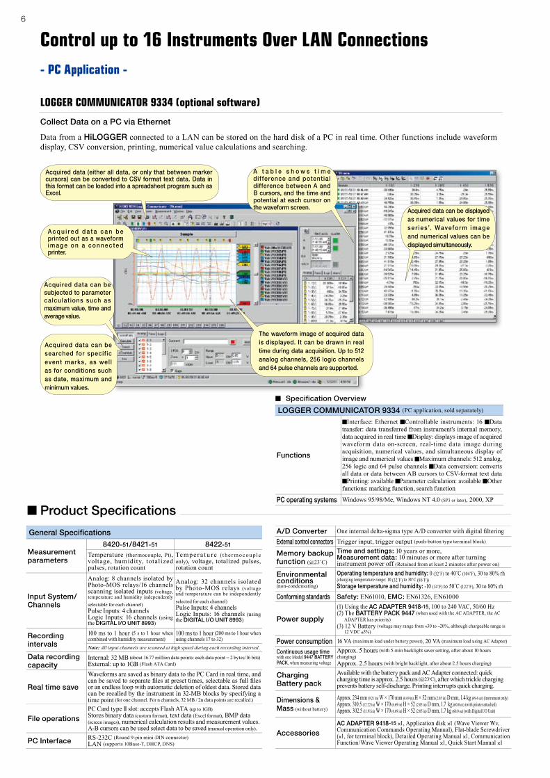
Data from a HiLOGGER connected to a LAN can be stored on the hard disk of a PC in real time. Other functions include waveform display, CSV conversion, printing, numerical value calculations and searching.
Acquired data can be subjected to parameter calculat ions such as maximum value, time and average value.
A t a b l e s h o w s t i m e dif ference and potential difference between A and B cursors, and the time and potential at each cursor on the waveform screen.
The waveform image of acquired data is displayed. It can be drawn in real time during data acquisition. Up to 512 analog channels, 256 logic channels and 64 pulse channels are supported.
Acquired data can be displayed as numerical values for time ser ies’. Waveform image and numerical values can be displayed simultaneously.
A c q u i r e d d a t a c a n b e printed out as a waveform im ag e on a conne c te d printer.
Acquired data can be searched for specif ic event marks, as wel l as for conditions such as date, maximum and minimum values.
Acquired data (either all data, or only that between marker cursors) can be converted to CSV format text data. Data in this format can be loaded into a spreadsheet program such as Excel.
Collect Data on a PC via Ethernet
Control up to 16 Instruments Over LAN Connections- PC Application -
LOGGER COMMUNICATOR 9334 (optional software)
■ Product Specifications
General Specifications
Measurement parameters
8420-51/8421-51 8422-51
Temperature (thermocouple, Pt), voltage, humidity, totalized pulses, rotation count
Te mp e r a t u r e (t he r mo c ou ple only), voltage, totalized pulses, rotation count
Input System/Channels
Analog: 8 channels isolated by Photo-MOS relays/16 channels scanning isolated inputs (voltage, temperature and humidity independently selectable for each channel)Pulse Inputs: 4 channelsLogic Inputs: 16 channels (using the DIGITAL I/O UNIT 8993)
Analog: 32 channels isolated by Photo-MOS relays (voltage and temperature can be independently selected for each channel)Pulse Inputs: 4 channelsLogic Inputs: 16 channels (using the DIGITAL I/O UNIT 8993)
Recording intervals
100 ms to 1 hour (5 s to 1 hour when combined with humidity measurement)
100 ms to 1 hour (200 ms to 1 hour when using channels 17 to 32)
Note: All input channels are scanned at high speed during each recording interval.
Data recording capacity
Internal: 32 MB (about 16.77 million data points: each data point = 2 bytes/16 bits)External: up to 1GB (Flash ATA Card)
Real time save
Waveforms are saved as binary data to the PC Card in real time, and can be saved to separate fi les at preset times, selectable as full fi les or an endless loop with automatic deletion of oldest data. Stored data can be recalled by the instrument in 32-MB blocks by specifying a time point (for one channel. For n channels, 32 MB / 2n data points are recalled.)
File operationsPC Card type II slot: accepts Flash ATA (up to 1GB)Stores binary data (custom format), text data (Excel format), BMP data (screen images), numerical calculation results and measurement values. A-B cursors can be used select data to be saved (manual operation only).
PC Interface RS-232C (Round 9-pin mini-DIN connector)LAN (supports 10Base-T, DHCP, DNS)
A/D Converter One internal delta-sigma type A/D converter with digital fi ltering
External control connectors Trigger input, trigger output (push-button type terminal block)
Memory backup function (@23˚C)
Time and settings: 10 years or more,Measurement data: 10 minutes or more after turning instrument power off (Retained from at least 2 minutes after power on)
Environmental conditions(non-condensating)
Operating temperature and humidity: 0 (32˚F) to 40˚C (104˚F), 30 to 80% rh (charging temperature range: 10 (32˚F) to 30˚C (86˚F))Storage temperature and humidity: -10 (14˚F) to 50˚C (122˚F), 30 to 80% rh
Conforming standards Safety: EN61010, EMC: EN61326, EN61000
Power supply
(1) Using the AC ADAPTER 9418-15, 100 to 240 VAC, 50/60 Hz(2) The BATTERY PACK 9447 (when used with the AC ADAPTER, the AC
ADAPTER has priority)(3) 12 V Battery (voltage may range from +30 to −20%, although chargeable range is
12 VDC ±5%)
Power consumption 16 VA (maximum load under battery power), 20 VA (maximum load using AC Adapter)
Continuous usage time with one Model 9447 BATTERY PACK, when measuring voltage
Approx. 5 hours (with 5-min backlight saver setting, after about 10 hours charging)Approx. 2.5 hours (with bright backlight, after about 2.5 hours charging)
Charging Battery pack
Available with the battery pack and AC Adapter connected: quick charging time is approx. 2.5 hours (@23˚C), after which trickle charging prevents battery self-discharge. Printing interrupts quick charging.
Dimensions & Mass (without battery)
Approx. 234 mm (9.21 in) W × 170 mm (6.69 in) H × 52 mm (2.05 in) D mm, 1.4 kg (49.4 oz) (instrument only)Approx. 310.5 (12.22 in) W × 170 (6.69 in) H × 52 (2.05 in) D mm, 1.7 kg (60.0 oz) (with printer attached)Approx. 302.5 (11.91 in) W × 170 (6.69 in) H × 52 (2.05 in) D mm, 1.7 kg (60.0 oz) (with Digital I/O Unit)
AccessoriesAC ADAPTER 9418-15 ×1, Application disk ×1 (Wave Viewer Wv, Communication Commands Operating Manual), Flat-blade Screwdriver (×1, for terminal block), Detailed Operating Manual ×1, Communication Function/Wave Viewer Operating Manual ×1, Quick Start Manual ×1
■ Specifi cation Overview
LOGGER COMMUNICATOR 9334 (PC application, sold separately)
Functions
■Interface: Ethernet ■Controllable instruments: 16 ■Data transfer: data transferred from instrument's internal memory, data acquired in real time ■Display: displays image of acquired waveform data on-screen, real-time data image during acquisition, numerical values, and simultaneous display of image and numerical values ■Maximum channels: 512 analog, 256 logic and 64 pulse channels ■Data conversion: converts all data or data between AB cursors to CSV-format text data ■Printing: available ■Parameter calculation: available ■Other functions: marking function, search function
PC operating systems Windows 95/98/Me, Windows NT 4.0 (SP3 or later), 2000, XP
7
Functional Specifications
Display
5.7-inch STN Color LCD (240 × 320 dots). Displays either waveforms only, waveforms and numerical values simultaneously, numerical values only or calculation results and waveforms simultaneously. Japanese/English language selectable. The most recent 16 MB of data (with one-channel recording) can be displayed by back scrolling.
Waveform compression and magnification
Time-axis: 1/2/5/10/20/30 seconds, 1/2/5/10/20/30 minutes, 1/2/5/10/12 hours, 1 day/division
Voltage-axis zoom: ×100, ×50, ×20, ×10, ×5, ×2, ×1, ×1/2
Search function Event marks can be searched
Calculation functions
Waveform parameter calculations: Up to four simultaneous calculations are supported: average, peak, maximum, minimum and effective values, timing of maximum and minimum values, and waveform processing calculation: displays sums and differences between channel waveforms
Communication functions(Controlled by PC)
■Data can be collected in real time using the optional LOGGER COMMUNICATOR 9334 (data collection software application).■Data in internal memory*1 and in the PC Card can be transferred by the FTP server function. *1 Data in internal memory can be transferred only when not measuring.■Remote control by communications commands (separate programming required)■Remote control by HTTP server function (with no special software other than a common Web browser, HiLOGGER settings, data acquisition and screen monitoring can be performed)
Communication functions(Sending to PC)
■Automatic data sending by FTP client function (periodically during measurement or after measuring, a file automatically saved to PC Card is automatically sent to an FTP server on the internal network or on a remote PC)■Automatic e-mail sending (upon trigger start/stop, trigger warning, power outage recovery, memory or card full status, an e-mail notification is sent to a PC on the local network or to a remote PC through an SMTP mail server)
Communication functions (PPP)
To communicate with a modem-equipped PC through the public telephone circuit, connect a standard modem to the RS-232C terminal using the RS-232C CABLE 9721.
MiscellaneousWaveform scroll, cursor measurement, scaling, automatic saving (binary/text selectable), start condition retention, settings saving, comment entry, event marking (for search), automatic setup, saves the most recent 16 MB of data (with one-channel recording) in internal memory
Trigger FunctionsTrigger source (conditions can be set for each channel)
Analog input: all channels, Pulse totalizer inputs: P1 to P4, Logic inputs LI-1 to LI-16 (using the DIGITAL I/O UNIT 8993), External trigger, Time trigger, Logical Product of each trigger source (AND), Logical Sum (OR)
External trigger Active low, valid pulse width H period 2.5 ms or more, L period 2.5 ms or more (with external trigger filter ON)
Trigger timing Start, Stop and Start/Stop (separate trigger conditions can be set to start and stop)
Trigger type(analog, pulse)
Level: Triggers when rising or falling through preset levelWindow: Triggers when entering or exiting range defined by preset upper and lower limit values
Trigger level resolution 0.5% f.s. (f.s. = 10 divisions)
Trigger type (logic) Pattern trigger by 1, 0 and × (don't care) (with the DIGITAL I/O UNIT 8993)
MiscellaneousPre-trigger (records period before trigger, can be set for real-time saving), Trigger output (open collector, 5V output, active low, at least 100 ms pulse width), Trigger mode (single, continuous)
Thermocouple Inputs (accuracy specified @23 ±5˚C, from 30 minutes after power on and after zero point adjustment, guaranteed for one year)
Input Terminals/ Impedance
Screw-type terminal block (recommended minimum wire diameter 0.32 mm*2), removable, supplied terminal block cover (all channel terminals are isolated from each other and chassis), Input impedance: 1MΩ (850kΩ when open-circuit polling is enabled)*2 Recommended wire: 0.14 to 1.5 mm2 single strand, or 0.14 to 1.0 mm2 twisted multi strand. To connect smaller thermocouple wire, use the TERMINAL UNIT 9329.
Setting range*3 Upper and lower limits depend on the measurement input range of each sensor
100˚C f.s. : -100 to 100˚C*3 (0.01˚C resolution)500˚C f.s. : -200 to 500˚C*3 (0.1˚C resolution)2000˚C f.s. : -200 to 2000˚C*3 (0.5˚C resolution)
Thermocouples are JIS C 1602-1995 compliant (except type W)
K: -200 to 1350˚C, E: -200 to 1000˚C, J: -200 to 1200˚C, T: -200 to 400˚C, N: -200 to 1300˚C, R: 400 to 1700˚C, S: 400 to 1700˚C, B: 400 to 1800˚C, W (WRe5-26): 400 to 2000˚CNote: Types W, R and S can measure from 0˚C, but measurements in this range are not guaranteed Standard. Reference contact: internally and externally switchable
AccuracyTypes K, E, J, T, N: ±0.05% f.s. ±1˚CTypes R, S, B, W: ±0.05% f.s. ±2˚C (applicable at 400˚C and above)Standard reference contact accuracy: ±1˚C (with internal compensation, add to measurement accuracy)
Max. allowable input 60 V DC (maximum voltage between input terminals that does not cause damage)
Max. rated voltage to earth
60 V DC (Upper limit voltage that does not cause damage when applied between input channel and chassis, and between each input channels)
Platinum resistance temperature sensor inputs (only in 8420-51/8421-51, accuracy specified @23 ±5˚C, from 30 minutes after power on and after zero point adjustment, guaranteed for one year)
Input terminal, detection current
Common thermocouple application, detection current: 1 mA, Input Resistance: 2 MΩ
Setting range*4 Upper and lower limits depend on the measurement input range of each sensor
100˚C f.s. : -100 to 100˚C*4 (0.01˚C resolution)500˚C f.s. : -200 to 500˚C*4 (0.1˚C resolution)2000˚C f.s. : -200 to 2000˚C*4 (0.5˚C resolution)
Resistance temperature sensor
Pt100: -200 to 800˚C, JPt100: -200 to 500˚C, Connection: 3-wire/4-wire (Pt100: JIS C 1604-1997, JPt100: JIS C 1604-1989)
Accuracy Pt100, JPt100: ±0.05% f.s. ±0.5˚C
Max. allowable input 60 V DC (maximum voltage between input terminals that does not cause damage)
Max. rated voltage to earth
60 V DC (Upper limit voltage that does not cause damage when applied between input channel and chassis, and between each input channels)
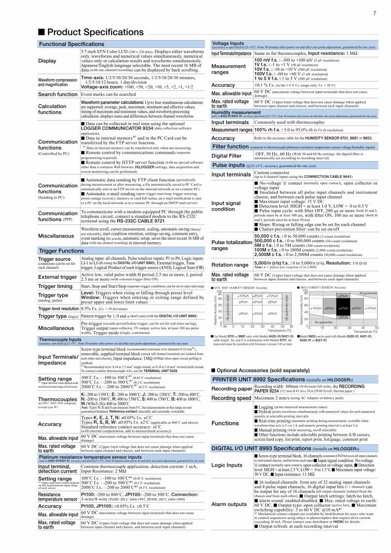
PRINTER UNIT 8992 Specifications (installs on HiLOGGERs)
Recording paper Recording width: 100mm (10 divisions full scale), the RECORDING PAPER 9234 (112 mm (4.41 in) × 18 m (59.06 ft) roll, thermal paper )
Recording speed Maximum 2 mm/s (using AC Adapter or battery pack)
Functions
■Logging (prints numerical measurement values) ■Hybrid (prints waveforms simultaneously with numerical values for each numerical quantity at selectable printing intervals)■Real-time printing (automatic printing during measurement, available when waveform time axis is 5 s to 1 d, and numeric printing interval is at least 5 s)■Manual printing (while measuring, on/off selectable)■Other functions include selectable printing between A/B cursors, screen hard copy, list print, report print, list/gauge, comment print
DIGITAL I/O UNIT 8993 Specifications (installs on HiLOGGERs)
Logic Inputs
■Screw-type terminal block, 16 channels (common GND between all input channels to instrument chassis, and between each input)■Input signal condition: No-voltage 'a' contact (normally open contact), open collector or voltage input, ■Detection level: HIGH = at least 2.5 V, LOW = 0 to 1.5 V, ■Maximum input voltage: 50 V DC, ■Input resistance: 1.1 MΩ
Alarm outputs
■16 isolated channels: from any of 32 analog input channels and 4 pulse input channels, 16 digital input bits (= 1 channel) can be output for any of 16 channels (all output channels isolated from the chassis and from each other), ■Output latch settings: latch/no latch, ■alarm sound: enabled/disabled, ■Max. rated voltage to earth: 60 V DC, ■Output type: open collector (active low), ■Maximum switching capability: 5 to 60 V DC @10 mA*5
*5 Mechanical contact outputs are available by modification for users who want to control sequencers using relays or photocouplers that require drive current exceeding 10 mA. Please contact your distributor or HIOKI for details.■Output refresh: at each recording interval
Voltage Inputs (accuracy is specified at 23 ±5˚C, from 30 minutes after power on and after zero point adjustment, guaranteed for one year)
Input Terminals/Impedance Same as for thermocouples, Input resistance: 1 MΩ
Measurement ranges
100 mV f.s. : -100 to +100 mV (5 μV resolution)1V f.s. : -1 to +1 V (50 μV resolution)10V f.s. : -10 to +10 V (500 μV resolution)100V f.s. : -60 to +60 V (5 mV resolution)1 to 5 V f.s. : 1 to 5 V (500 μV resolution)
Accuracy ±0.1 % f.s. (in the 1-5 V f.s. range only, f.s. = 10 V)
Max. allowable input 60 V DC (maximum voltage between input terminals that does not cause damage)
Max. rated voltage to earth
60 V DC (Upper limit voltage that does not cause damage when applied between input channel and chassis, and between each input channels)
Humidity measurement (only in 8420-51/8421-51, accuracy specified @23 ±5˚C, from 30 minutes after power on and after zero point adjustment, guaranteed for one year)
Input terminals Commonly used with thermocouples
Measurement ranges 100% rh f.s. : 5.0 to 95.0% rh (0.1% rh resolution)
Accuracy Refer to the accuracy table for the HUMIDITY SENSOR 9701, 9681 or 9653.
Filter function (common to thermocouple/platinum resistance temperature sensor/voltage/humidity inputs)
Digital Filter OFF, 50 Hz, 60 Hz (With 50 and 60 Hz settings, the digital filter is automatically set according to recording interval)
Pulse inputs (@23 ±5˚C, accuracy guaranteed for one year)
Input terminals Custom connector(up to 4 channel inputs using the CONNECTION CABLE 9641)
Input signal condition
■No-voltage 'a' contact (normally open contact), open collector or voltage input■ Insulated between all pulse input channels and instrument chassis, and between each pulse input channel■Maximum input voltage: 15 V DC■Detection level: HIGH = at least 1.0 V, LOW = 0 to 0.5 V■Pulse input cycle: with filter OFF, 200 μs or more (both H and L periods must be at least 100 μs), with filter ON, 100 ms or more (both H and L periods must be at least 50 ms)■Slope: Rising or falling edge can be set for each channel■Chatter-prevention filter: can be set on/off
Pulse totalization ranges
50,000 c f.s. : 0 to 50,000 counts (1-count resolution)500,000 c f.s. : 0 to 500,000 counts (10-count resolution)5M c f.s. : 0 to 5M counts (100-count resolution)100M c f.s. : 0 to 100M counts (2,000-count resolution)2,500M c f.s. : 0 to 2,500M counts (50,000-count resolution)
Rotation range 5,000/n (r/s) f.s. : 0 to 5,000/n (r/s); Resolution: 1/n (r/s) Note: n = pulses per rotation (1 to 1,000)
Max. rated voltage to earth
60 V DC (Upper limit voltage that does not cause damage when applied between input channel and chassis, and between each input channels)
■ Optional Accessories (sold separately)
■ Product Specifications
■ Use Model 9701 or 9681 only with Models 8420-51/8421-51, cable length: 3m, and if in combination with Models 9701, the main unit must be installed with firmware version 3.05 or later.
■ Model 9653 can be used with Models 8420-51, 8421-51, 8420-01 or 8421-01.

HEAD OFFICE :81 Koizumi, Ueda, Nagano, 386-1192, JapanTEL +81-268-28-0562 / FAX +81-268-28-0568 E-mail: [email protected]
HIOKI USA CORPORATION :6 Corporate Drive, Cranbury, NJ 08512 USATEL +1-609-409-9109 / FAX +1-609-409-9108E-mail: [email protected]
DISTRIBUTED BY
All information correct as of Jun. 18, 2009. All specifi cations are subject to change without notice. 8420-51E7-96M-03KR Printed in Korea
HIOKI (Shanghai) Sales & Trading Co., Ltd. :1608-1610 Shanghai Times Square Offi ce, 93 Huai Hai Zhong Road, Shanghai, P.R.China POSTCODE: 200021TEL +86-21-6391-0090/0092 FAX +86-21-6391-0360E-mail: [email protected] Offi ce :A-2602 Freetown, 58 Dong San Huan Nan RoadBeijing, P.R.China POSTCODE: 100022TEL +86-10-5867-4080/4081 FAX +86-10-5867-4090E-mail: [email protected] Offi ce :Room A-3206, Victory PlazaServices Center, No.103, Tiyuxi Road, Guangzhou, P.R.China POSTCODE:510620TEL +86-20-38392673/2676 FAX +86-20-38392679E-mail: [email protected]
Options in Detail Note: Product names in this publication are trademarks or registered trademarks of their respective companies.
■ Appearance/Dimension Illustration
With printer attached With Digital I/O Unit attachedMain unit
234 mm(9.21 in)
170
mm
(6.6
9 in
)
170
mm
(6.6
9 in
)52
mm
(2.0
5 in
)
310.5 mm (12.22 in) 302.5 mm (11.91 in)
52 m
m(2
.05
in)
170
mm
(6.6
9 in
)
Supplied Accessories: AC ADAPTER 9418-15 ×1, Application Disk ×1 (Wave Viewer Wv, Communication Commands Operating Manual), Flat-blade Screwdriver (×1, for terminal block), Detailed Operating Manual ×1, Communication Function/Waveform Viewer Operating Manual ×1, Quick Start Manual ×1
MEMORY HiLOGGER 8420-51 (8ch, mai unit)
MEMORY HiLOGGER 8421-51 (16ch, main unit)
MEMORY HiLOGGER 8422-51 (32ch, main unit)
Printer options
PRINTER UNIT 8992 Printing width 100 mm (3.94
in), used together with the HiLOGGER main body
Carrying case
CARRYING CASE 9648 Hard case type, for storing options
PROTECTIVE CASE 9649 Includes storage for options, simple
water-resistant type with rubber grommets for cables to permit measuring while the case is closed
FIXED STAND 9652-01 Enables installation in standard DIN
rails, other features include belt attachment, wall hanging and slanted bench mounting
Power Supply *Sold separately
BATTERY PACK 9447 7.2 V, 2400 mAh
CHARGE STAND 9643 Independent of the HiLOGGER
series main unit, use with the AC ADAPTER 9418-15 to charge one Model 9447.
AC ADAPTER 9418-15 Universal 100 to 240 V AC,
12 V DC/ 2.5 A output
By using the AC adapter provided with the HiLOGGER, the BATTERY
PACK 9447 can be charged without the CHARGE STAND 9643. If the charging stand, AC adapter, and battery pack are purchased separately, standalone battery charging is possible.
HUMIDITY SENSOR 9701 Use Model 9701 only with Models
8420-51/8421-51, cable length: 3m,and the main unit must be installed
with firmware version 3.05 or later.
LOGGER COMMUNICATOR 9334 Data collection application software
required for LAN connection on Windows 95/98/Me, Windows NT 4.0/2000/XP
Input cables, Other options
RS-232C CABLE 9612 9-pin mini DIN to 9-pin
Dsub, crossover cable for PC, 1.5m (4.92 ft) length
CONNECTION CABLE 9641
(for pulse inputs), 1.5m (4.92 ft) length
RS-232C CABLE 9721 9-pin mini DIN to 9-pin Dsub,
straight-through cable for modem, 1.5m (4.92 ft) length
LAN CABLE 9642 Straight-through cable with
crossover cable, 5m (16.41 ft) length
DIGITAL I/O UNIT 8993 Input type: No-voltage 'a' contact (normally open
contact), open collector, or voltage common with 16 channels/GND, Output type: 16 channels, open collector isolated, used in combination with the HiLOGGER instrument
Note: The 8993 is required for dual-battery HiLOGGER operation.
Alarm Output and Logic Input
PC CARD 256M 9727 (256 MB capacity)
PC CARD 512M 9728 (512 MB capacity)
PC CARD 1G 9729 (1 GB capacity)
PC Card PrecautionUse only PC Cards sold by HIOKI. Compatibility and performance are not guaranteed for PC cards made by other manufacturers. You may be unable to read from or save data to such cards.
Supplied with PC Card adapter
Removable storage
PAPER WINDER 220H Paper width: 70 to 220 mm (2.76 to 8.66
in), using special-purpose AC adapter
RECORDING PAPER 9234
112 mm (4.41 in) × 18 m (59.06 ft), 10 rolls set
Not CE marked
Supplied Accessories
Note: Thermocouples are not provided by HIOKI, and must be purchased from a separate vendor.
TERMINAL UNIT 9329 M3 (mm) screw terminals. The recommended wire
diameter for the instrument's terminal block is 0.32 mm (0.0126 inch). Use this unit to secure smaller-diameter wire.
Built in the 9329