
Membrane per la separazione di CO2 e reattori a membrana ... · is the ratio of the total feed...
24
Angelo Basile, Adolfo Iulianelli, Pietropaolo Morrone ITM-CNR. Istituto per la Tecnologia delle Membrane – Via P. Bucci 87030 Arcavacata di Rende (CS) – Italy Membrane per la separazione di CO2 e reattori a membrana per il suo uso
Transcript of Membrane per la separazione di CO2 e reattori a membrana ... · is the ratio of the total feed...
Angelo Basile, Adolfo Iulianelli, Pietropaolo Morrone
ITM-CNR. Istituto per la Tecnologia delle Membrane – Via P. Bucci 87030 Arcavacata di Rende (CS) – Italy
Membrane per la separazione di CO2 e reattori a membrana per il suo uso
Summary
1. Membrane in gas separation: flow patterns
• complete mixing • parallel flow (co-current and counter current flow) • cross flow
2. Numerical simulation of membrane gas separation systems: • Key parameters
3. Parametric analysis:
• one stage removal • multi-stage removal
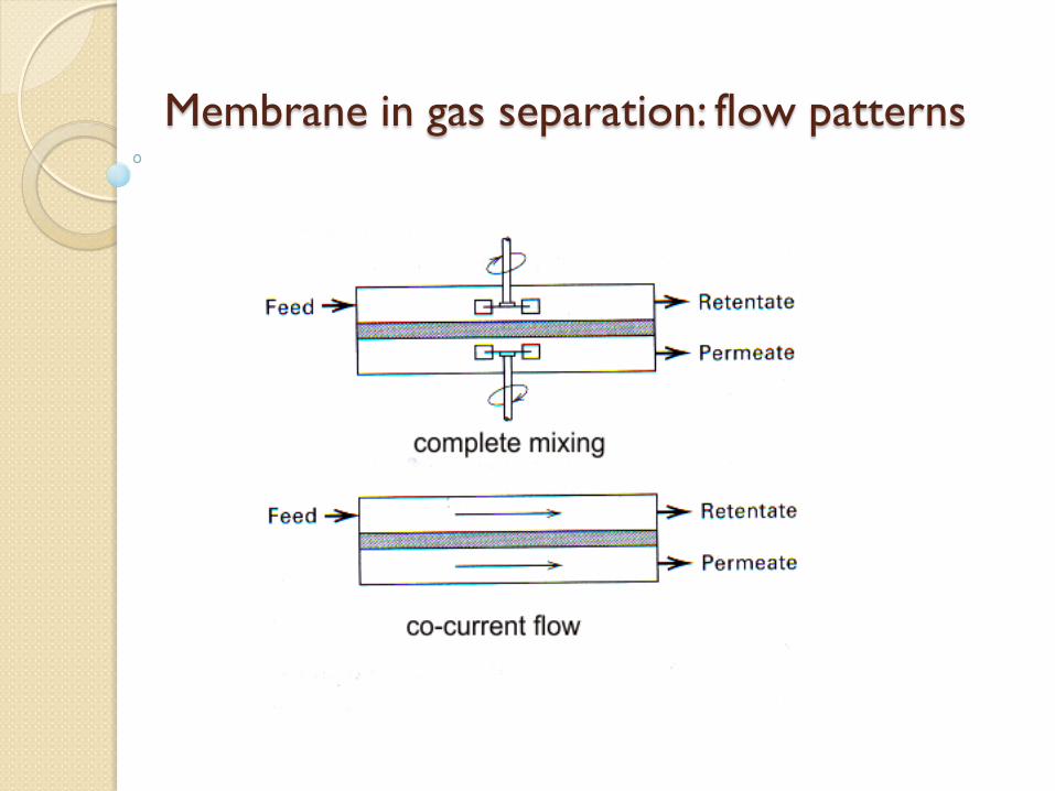
Membrane in gas separation: flow patterns

Membrane in gas separation: flow patterns
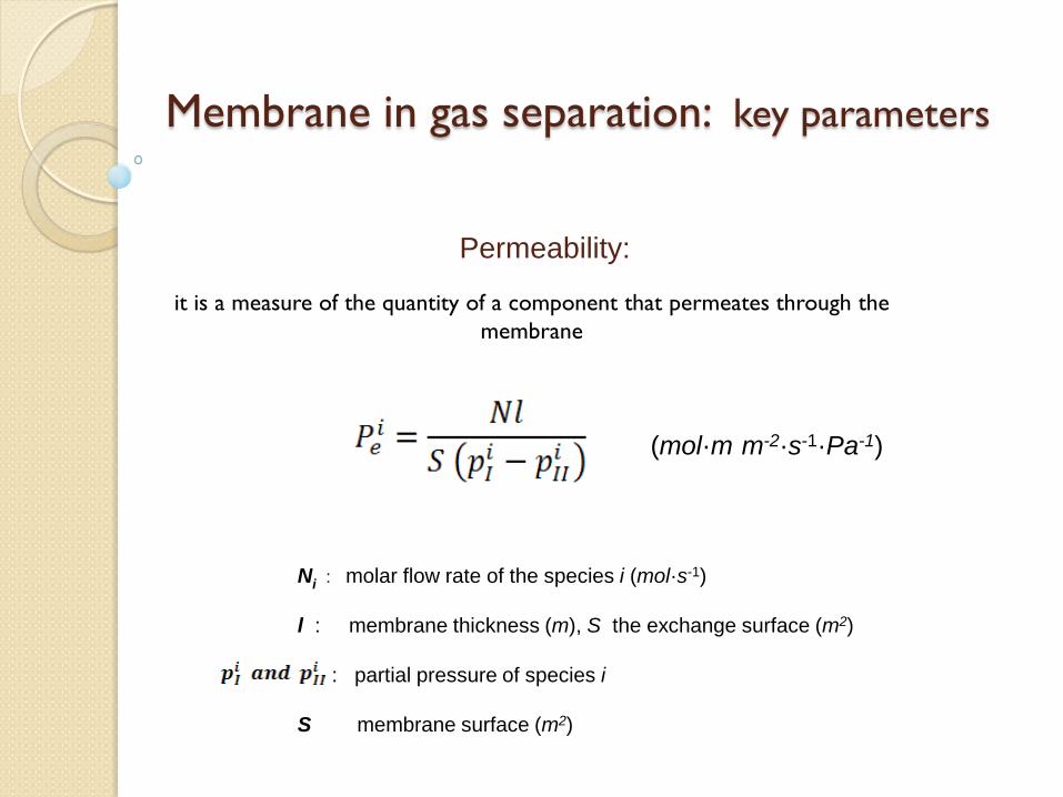
Membrane in gas separation: key parameters
Permeability:
(mol·m·m-2·s-1·Pa-1)
it is a measure of the quantity of a component that permeates through the membrane
Ni : molar flow rate of the species i (mol·s-1) l : membrane thickness (m), S the exchange surface (m2) : partial pressure of species i S membrane surface (m2)
Membrane in gas separation: key parameters
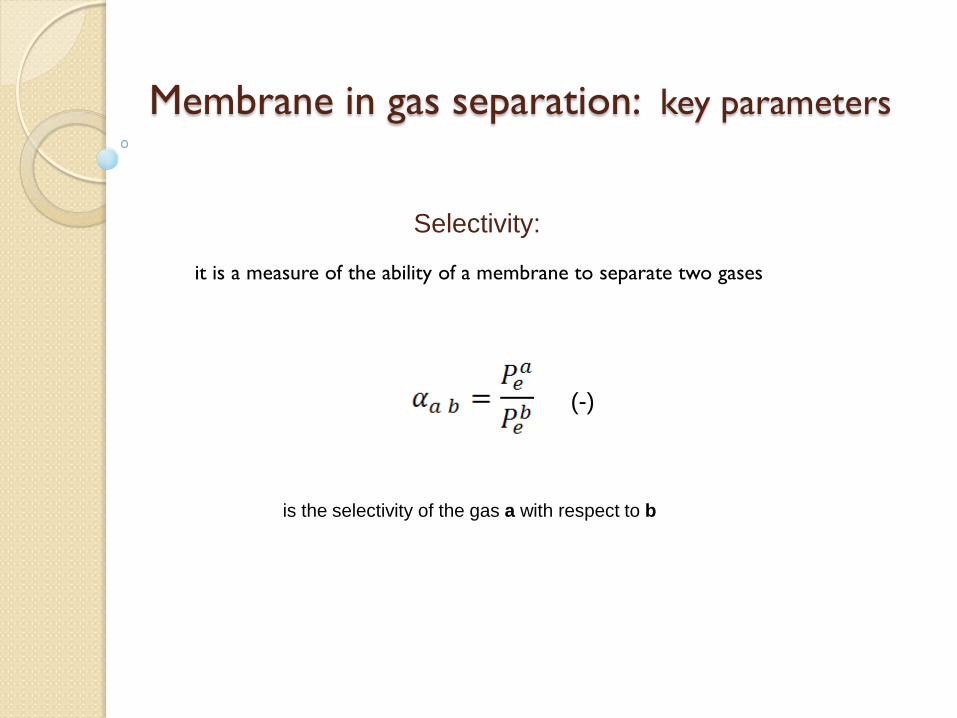
Selectivity:
(-)
it is a measure of the ability of a membrane to separate two gases
is the selectivity of the gas a with respect to b
Membrane in gas separation: key parameters
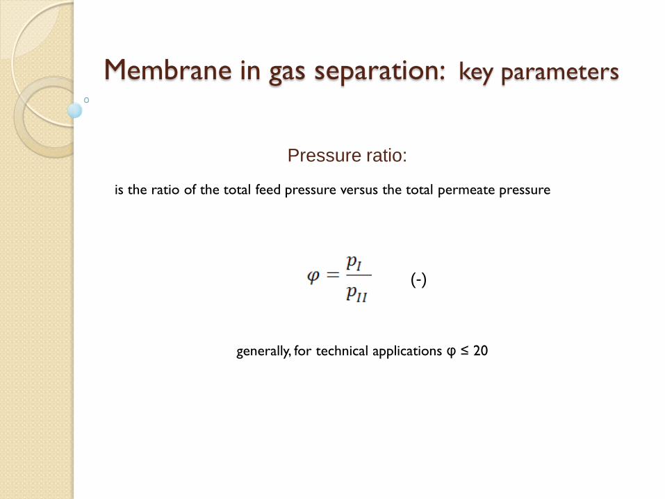
Pressure ratio:
(-)
is the ratio of the total feed pressure versus the total permeate pressure
generally, for technical applications φ ≤ 20
Membrane in gas separation: key parameters
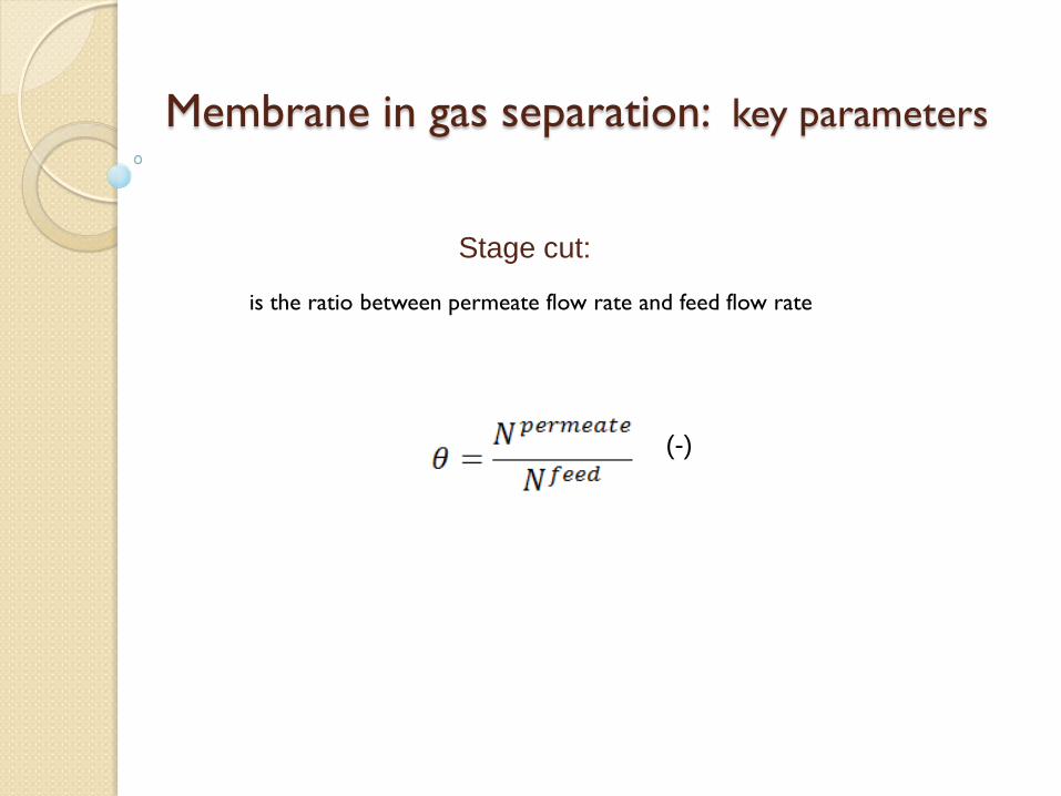
Stage cut:
(-)
is the ratio between permeate flow rate and feed flow rate
Membrane in gas separation: key parameters
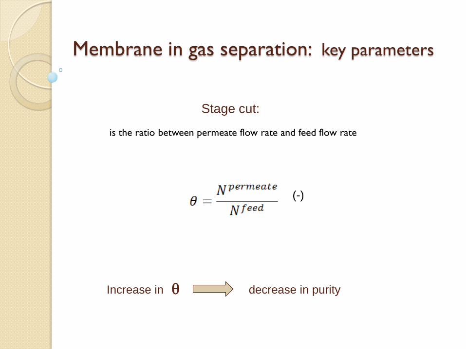
Stage cut:
(-)
is the ratio between permeate flow rate and feed flow rate
θ Increase in decrease in purity
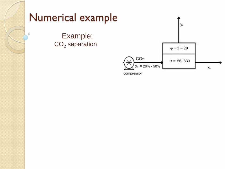
Numerical example
Example: CO2 separation
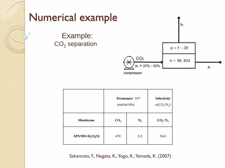
Numerical example
Example: CO2 separation
Permeance ·1012
(mol/m2sPa)
Selectivity
α(CO2/N2)
Membrane CO2 N2 CO2/ N2
APS/MS/Al2O3(S) 470 8.3 56,6
Sakamoto, Y., Nagata, K., Yogo, K., Yamada, K. (2007)
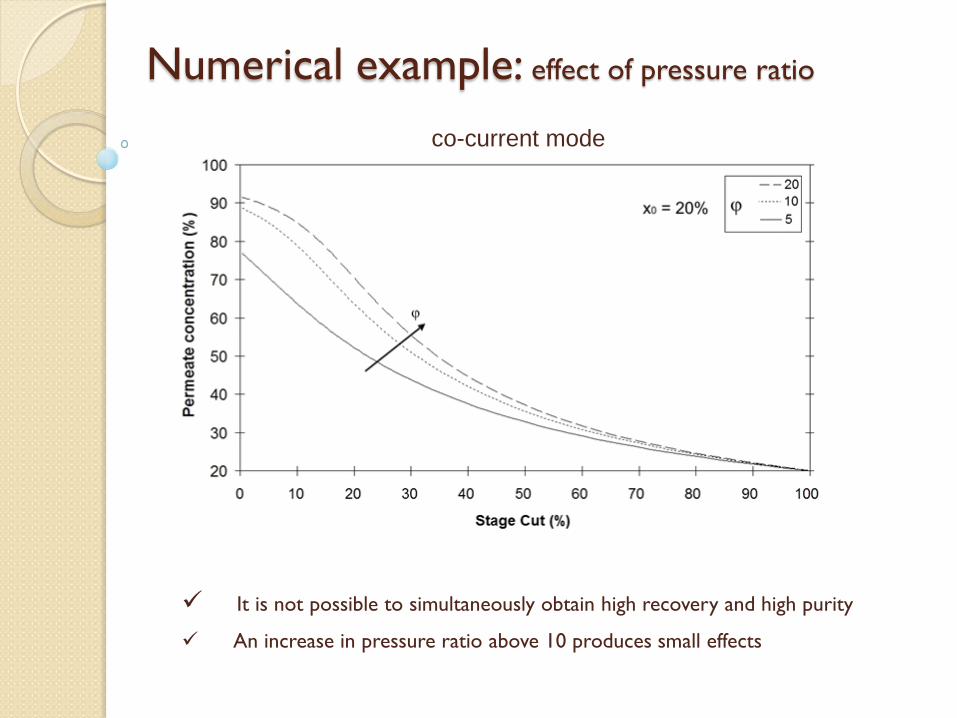
Numerical example: effect of pressure ratio
It is not possible to simultaneously obtain high recovery and high purity
An increase in pressure ratio above 10 produces small effects
co-current mode
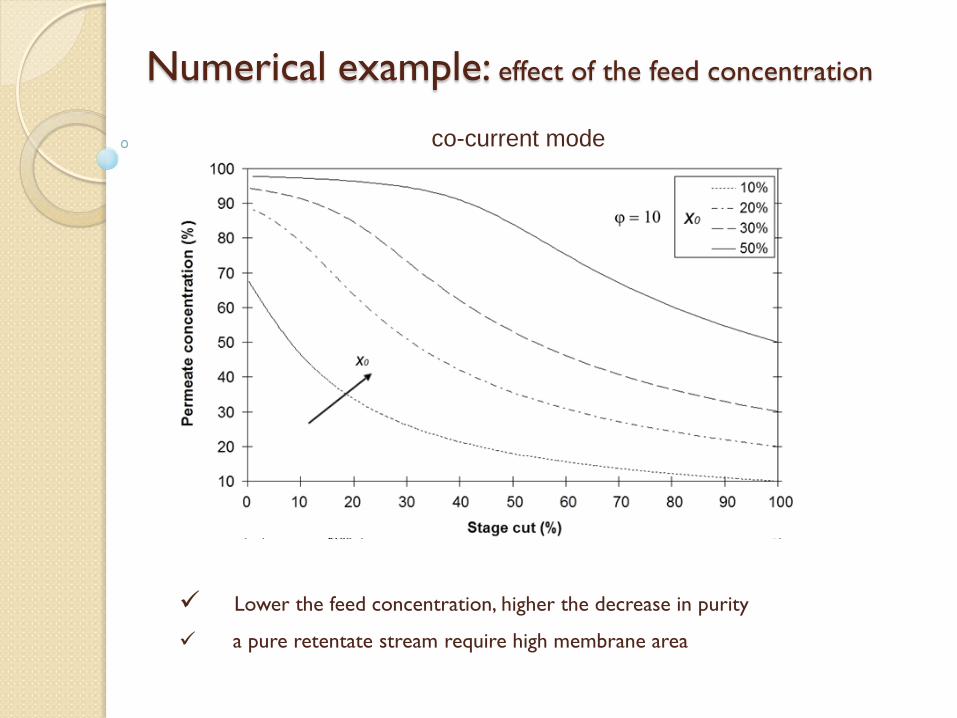
Numerical example: effect of the feed concentration
Lower the feed concentration, higher the decrease in purity
a pure retentate stream require high membrane area
co-current mode
CO2 recovery
recovery = CO2 captured / CO2 in the feed
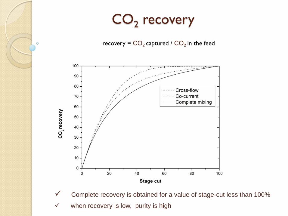
Complete recovery is obtained for a value of stage-cut less than 100%
when recovery is low, purity is high
recovery = CO2 captured / CO2 in the feed
CO2 recovery
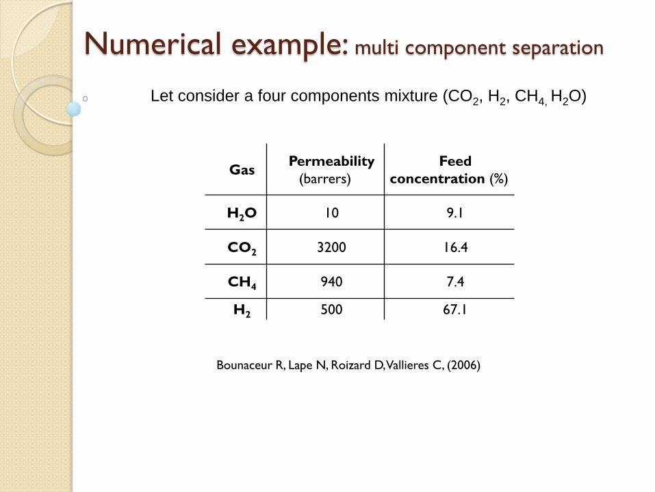
Numerical example: multi component separation
Let consider a four components mixture (CO2, H2, CH4, H2O)
Gas Permeability
(barrers) Feed
concentration (%)
H2O 10 9.1
CO2 3200 16.4
CH4 940 7.4
H2 500 67.1
Bounaceur R, Lape N, Roizard D, Vallieres C, (2006)
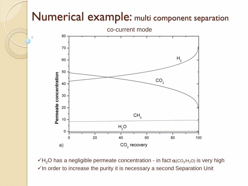
Numerical example: multi component separation
H2O has a negligible permeate concentration - in fact α(CO2/H2O) is very high In order to increase the purity it is necessary a second Separation Unit
co-current mode

Numerical example: multi component separation
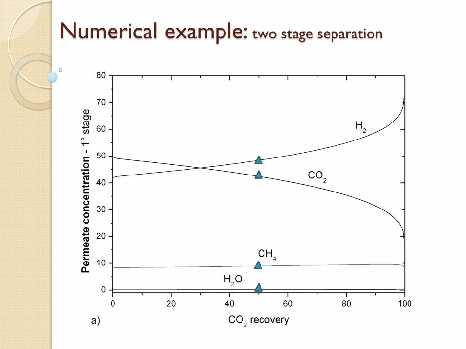
Numerical example: two stage separation
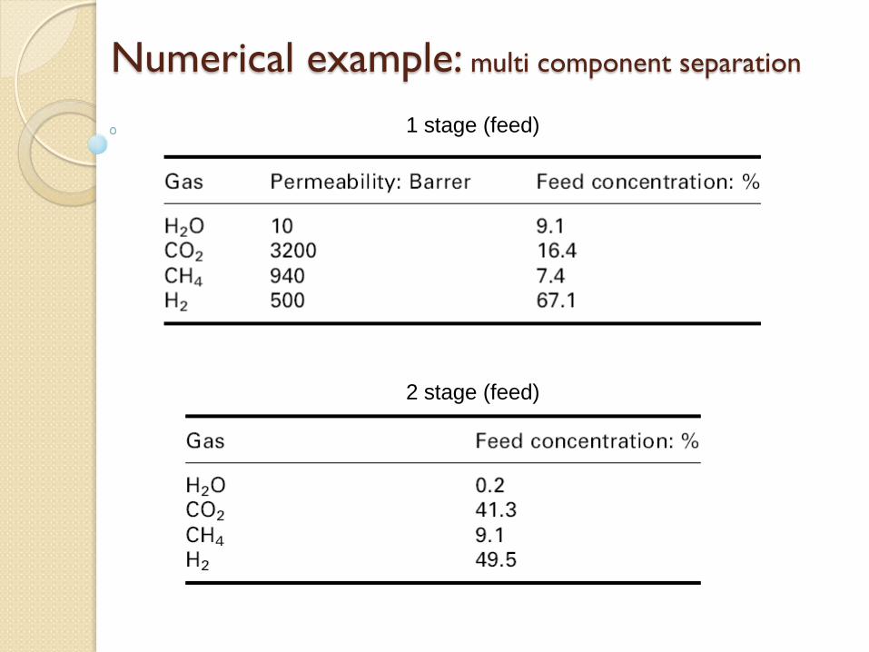
Numerical example: multi component separation
2 stage (feed)
1 stage (feed)

Numerical example: two stage separation
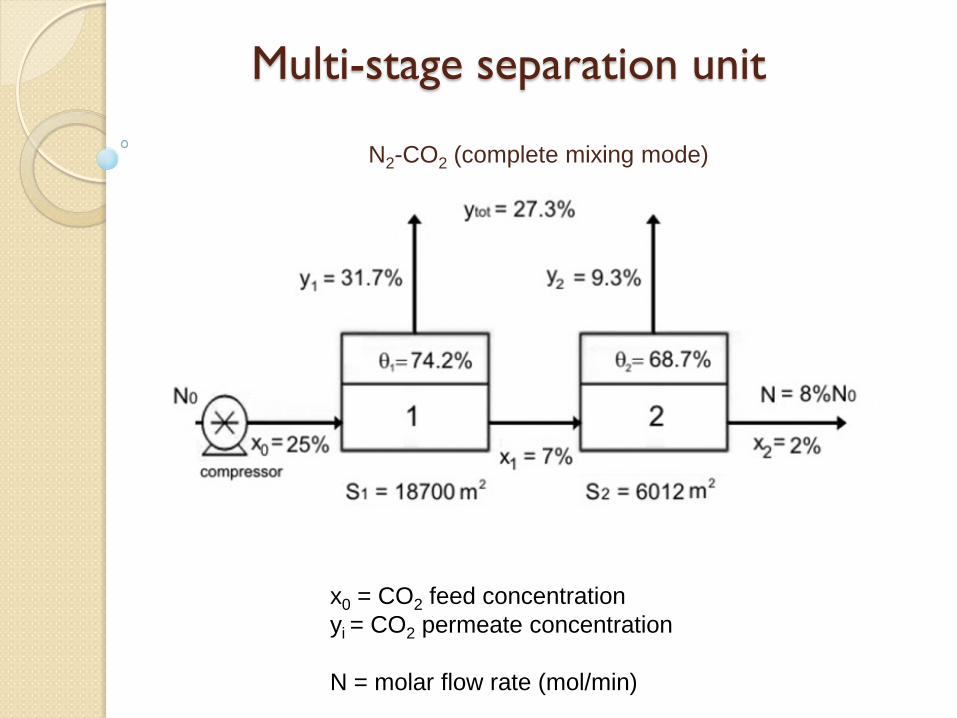
Multi-stage separation unit
N2-CO2 (complete mixing mode)
x0 = CO2 feed concentration yi = CO2 permeate concentration N = molar flow rate (mol/min)
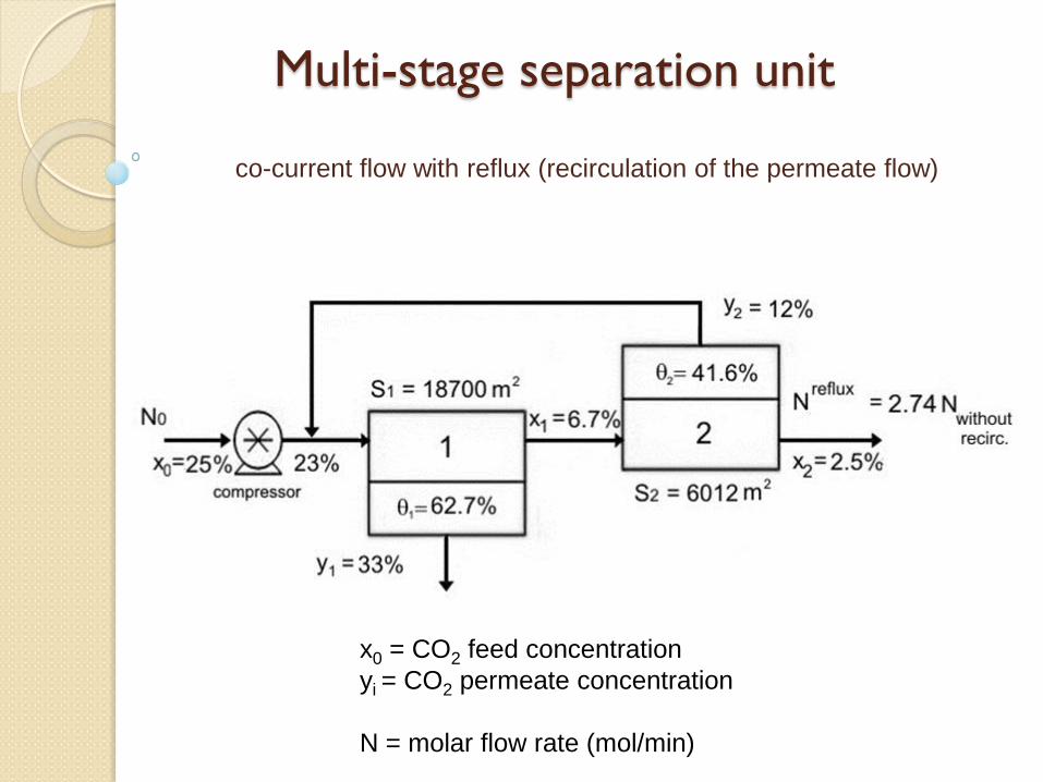
Multi-stage separation unit
co-current flow with reflux (recirculation of the permeate flow)
x0 = CO2 feed concentration yi = CO2 permeate concentration N = molar flow rate (mol/min)

Grazie per l’attenzione


![The New Italian Code of Criminal Procedure: The Difficulties of … · 2020. 2. 27. · MARAFIOTI, MAXI-INDAGINI]; LUCA MARAFOTI, LA SEPARAZIONE DEl aIJIDIZI PENAL! [THE SEVERANCE](https://static.fdocuments.in/doc/165x107/612e0fd31ecc515869429397/the-new-italian-code-of-criminal-procedure-the-difficulties-of-2020-2-27-marafioti.jpg)


