MEGA - J&M Manufacturing · MEGA REMOTE 8 the control system. To use this tool, connect the Palm™...
23
MEGA RADIO REMOTE CONTROL SYSTEM -PRELIMINARY- INSTALLATION AND OPERATION MANUAL J&M 3A2391BJ.doc March 29, 2012 BJ
Transcript of MEGA - J&M Manufacturing · MEGA REMOTE 8 the control system. To use this tool, connect the Palm™...

MEGA RADIO REMOTE CONTROL SYSTEM
-PRELIMINARY-
INSTALLATION AND OPERATION MANUAL
J&M
3A2391BJ.doc March 29, 2012
BJ

MEGA REMOTE
1
INDEX DESCRIPTION ................................................................................... 2
TRANSMITTER AND RECEIVER SYNCHRONIZATION .......................... 2
INDICATOR LEDs .............................................................................. 4
LCD DISPLAY .................................................................................... 4
OUTPUTS .......................................................................................... 4
INSTALLATION ................................................................................. 4
BEFORE APPLYING POWER! .............................................................. 5
OPERATION ...................................................................................... 6
Tare ............................................................................................... 6
Weight to dispense ........................................................................ 6
Auto Reset ..................................................................................... 7
Enable/Disable Display .................................................................. 7
Scale Unit Setting .......................................................................... 7
USING THE OPTIONAL PALM™ INTERFACE ....................................... 7
DIAGNOSTIC .................................................................................. 8
HISTOGRAM ................................................................................... 9
FILE TRANSFER ............................................................................ 10
CALIBRATION .............................................................................. 11
WIRING .......................................................................................... 13
ROUTINE MAINTENANCE ................................................................ 14
MAINTENANCE PRECAUTIONS ........................................................ 14
TROUBLESHOOTING ....................................................................... 14
TROUBLESHOOTING CHART ............................................................ 16
ERROR CODES ................................................................................. 17
TRANSMITTER PICTORIAL .............................................................. 19
RECEIVER PICTORIAL ..................................................................... 20
SPECIFICATIONS ............................................................................ 21
INSTRUCTION TO THE USER ........................................................... 22

MEGA REMOTE
2
DESCRIPTION The MEGA REMOTE is a state
of the art microprocessor
based Radio Frequency (RF)
control system. It will provide
the operator the ability to
wirelessly operate equipment.
The operator is required to
follow all OSHA www.osha.gov
safety standards when
operating the equipment.
The remote control system
consists of the handheld radio
transmitter and receiver
module. Additional optional
equipment such as wiring
harnesses and Palm™
interface tools may be
available.
The transmitter is equipped
with pushbutton switches for
the various functions and an
LCD display to show
equipment functions and
status. The transmitter runs
on 2 AA alkaline batteries.
The system’s radio receiver
has ON/OFF outputs to
accommodate the functions
available on the transmitter.
All outputs are current-
sourcing. It also includes a
port for RS-232
communication, used for
linking external equipment to
the receiver and performing
any software updates via the
optional Palm interface tool.
TRANSMITTER AND RECEIVER SYNCHRONIZATION Each radio remote system is
designed to operate with a
unique radio ID code and RF
channel sequence. Each
receiver is programmed to
respond only to the
MEGA REMOTE
3
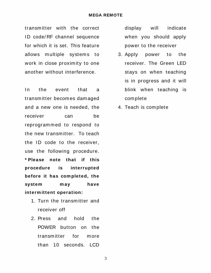
transmitter with the correct
ID code/RF channel sequence
for which it is set. This feature
allows multiple systems to
work in close proximity to one
another without interference.
In the event that a
transmitter becomes damaged
and a new one is needed, the
receiver can be
reprogrammed to respond to
the new transmitter. To teach
the ID code to the receiver,
use the following procedure.
*Please note that if this
procedure is interrupted
before it has completed, the
system may have
intermittent operation:
1. Turn the transmitter and
receiver off
2. Press and hold the
POWER button on the
transmitter for more
than 10 seconds. LCD
display will indicate
when you should apply
power to the receiver
3. Apply power to the
receiver. The Green LED
stays on when teaching
is in progress and it will
blink when teaching is
complete
4. Teach is complete

MEGA REMOTE
4
INDICATOR LEDs
The receiver module can
identify problems with the
system in the form of an error
code. Check the red indicator
on the receiver to diagnose
system problems. Then, refer
to the ERROR CODE CHART in
this manual for explanation of
the error codes. The green
LED indicator will blink on the
receiver during normal
communication.
LCD DISPLAY Pressing the POWER button
briefly will turn the LCD
backlight on. It will stay on
until the POWER button is
pressed briefly again.
OUTPUTS Each of the outputs from the
receiver module is designed
with built-in short circuit and
overload protection. The
outputs can also detect a no-
load or broken wire condition.
These error conditions are
evident by the red LED
indicator on the receiver
module or the HISTOGRAM
page on the optional Palm
Pilot™.
The ON/OFF outputs will
indicate an error under no
load or broken wire status if
NOT activated, and will detect
a short IF activated.
INSTALLATION Refer to the WIRING CHART
in this manual for hookup of
the harness.
To install the receiver module,
use the two mounting holes
provided on the enclosure to
attach it in a vertical manner

MEGA REMOTE
5
with the connectors facing
down. Please take extra
caution not to damage
internal components while
installing. For high vibration
applications, use shock
absorbing mounts. It is
advised to mount the unit as
high as possible, keeping
clear of metal obstructions
around the antenna which
might affect RF performance.
The main power to the
receiver should be connected
through a switched, fused line
capable of 20 amps. For best
results, connect the power
(+) to the receiver via an
auxiliary terminal of the
ignition switch, PTO switch, or
ignition relay. Be sure that the
ground (-) is connected
securely to the chassis or
battery with a star washer
which digs into the base metal
to insure good contact.
All connections must be
properly insulated to protect
against shorts.
Seal all connections with a
non-conductive silicone
grease to prevent corrosion.
BEFORE APPLYING POWER! Check power and ground
for proper polarity.
Check the wiring harness
for possible shorts before
connecting to output
devices (i.e. valves and
relays) by checking each
mating pin terminal.
Verify that the transmitter
batteries are fresh.
Read the rest of this

MEGA REMOTE
6
manual.
OPERATION
Power must be applied to the
receiver module for the
system to work.
Pressing the POWER button
will turn on the transmitter.
Pressing and holding the
POWER button until the LCD
display goes blank will turn off
the transmitter. If the
transmitter goes out of range
for more than 2 seconds, all
latched outputs will turn off as
a safety feature.
Use the buttons on the
keypad to operate the desired
functions.
To save battery life, the
transmitter will turn off when
it is idle (no functions are
used) for period greater than
15 minutes. The user must
press the POWER button at
this point to restore
transmitter operation.
The transmitter will NOT go
to sleep as long as the
receiver has power applied
to it.
Tare
In order to tare the unit, hold
down the TARE pushbutton on
the weight screen for 3
seconds.
Weight to dispense
In the Weight To Dispense
screen, to set the default
Weight To Dispense press
and hold the SCROLL
pushbutton for 3 seconds. The

MEGA REMOTE
7
first unit to change is the
weight, which will start
blinking. Using the UP/DOWN
buttons the weight can be
changed, to move to the next
unit press the SCROLL once
which will give the control to
change the default door.
Holding the SCROLL
pushbutton for another 3
seconds will save the new
weight.
Auto Reset
After setting a weight to
dispense, pressing the CONV
START push button will start
the automatic dispense mode
and will continue to unload
until it almost reaches the
selected weight, then the unit
will close the door and will
open the selected door again
for fine tuning until the unload
is completed.
Holding the scroll button on
the weight to dispense page
for 4 seconds, will get the unit
into auto mode again .
Enable/Disable Display
Hold both UP and DOWN
pushbuttons simultaneously
for 10 seconds to enable or
disable the display.
Scale Unit Setting
a. Serial Baud rate:
9600
b. Parity: None
c. Data bits: 8
d. Stop bits: 1
USING THE OPTIONAL PALM™ INTERFACE The Patented Palm Pilot™
interface, US patent No.
6,907,302, software is a very
useful tool for troubleshooting

MEGA REMOTE
8
the control system.
To use this tool, connect the
Palm™ serial cable to the
serial connector on the
receiver control harness or
adaptor, and apply power to
the system.
Main Page
Use the Palm’s stylus pen and
tap the icon J&M 1.0 to
launch the application.
DIAGNOSTIC
Tap the Diagnostic button to
see the diagnostic screens,
which shows the present state
of remote communications,
and system I/O.
RF Communications Page
When the round circle next to
a label is dark, the
corresponding ON/OFF input
or output is sensed to be
active or ON.

MEGA REMOTE
9
Digital Inputs Pages
Tap the Next Page button to
switch between pages of
inputs. Tap the button labeled
Outputs to view output
screens.
ON/OFF Outputs Page
HISTOGRAM
Tap the Histogram icon to see
a set of screens that show
which error codes are active
and how many times the
specific error code has been
active.

MEGA REMOTE
10
Histogram Page
This feature can be used to
troubleshoot machine wiring
and other problems. Tapping
the Reset button resets the
error code counts. The
password to reset error codes
is 1262. Tapping Next and
Back allows access to all the
histogram pages. Tap the
Done button to return to the
main menu.
FILE TRANSFER Tap the File Transfer
button to send new program
files from the Palm to the
receiver. New programs are
uploaded to the Palm via the
Palm™ desktop as a *.pdb file
using HotSync™.
File Transfer Page
This is only used for software
updates to the receiver. Tap
the ‘i’ icon for more
information on this procedure.

MEGA REMOTE
11
CALIBRATION To change the configuration of
the outputs, tap the
Calibration icon.
Calibration page
The password to gain access
to the calibration screens is
1262. In these screens,
configuration for proportional
outputs is available.
Output selection menu
To adjust a proportional
output’s configuration, use
the following procedure:
1. Select the output to
change from the first
drop-down menu
2. Select the parameter of
the output to change
from the second drop-
down menu
3. Enter the new value on
the line above the
Factory Setting button

MEGA REMOTE
12
by tapping on the line
and using the scratch
pad to enter a new value
4. Tap the Save button to
send the setting to
memory
The lines to the right of the
parameter indicate the
present value of the output (if
active).
Calibration parameters menu
Tap the Factory Setting
button to return all outputs to
standard values. Tap Save to
send these settings to
memory. Tap Done and Exit
to quit configuration and
return to the main menu.
The following can be adjusted
as needed:
1. Open Time – The
amount of time that the
output stays on
MEGA REMOTE
13
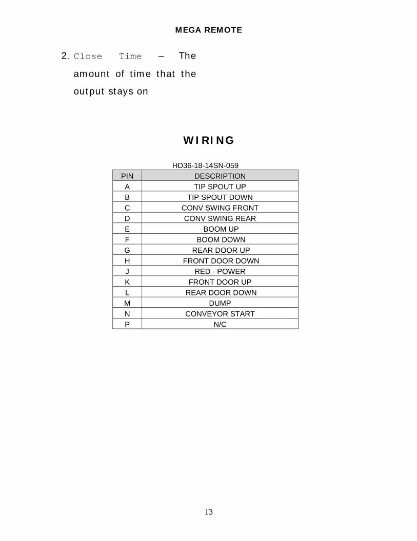
2. Close Time – The
amount of time that the
output stays on
WIRING
HD36-18-14SN-059
PIN DESCRIPTION
A TIP SPOUT UP
B TIP SPOUT DOWN
C CONV SWING FRONT
D CONV SWING REAR
E BOOM UP
F BOOM DOWN
G REAR DOOR UP
H FRONT DOOR DOWN
J RED - POWER
K FRONT DOOR UP
L REAR DOOR DOWN
M DUMP
N CONVEYOR START
P N/C

MEGA REMOTE
14
ROUTINE MAINTENANCE Clean transmitter regularly
with a damp cloth and mild
detergent.
Inspect electrical wiring for
wear points or other damage.
Repair as required.
Inspect all connections for
looseness or corrosion.
Tighten and/or "seal" as
necessary.
MAINTENANCE PRECAUTIONS When performing any
inspection or maintenance
work on the remote system,
always exercise care to
prevent injury to yourself and
others or damage to the
equipment. The following are
general precautions, which
should be closely followed in
carrying out any maintenance
work.
Do not have hydraulic power
available to the valves when
performing electrical tests.
Never operate or test any
function if any person is in an
area where they could be hurt
by being hit or squeezed by
the hydraulic equipment.
Turn power off before
connecting or disconnecting
valve coils or other electrical
loads.
TROUBLESHOOTING This next section provides
basic operator level
troubleshooting for the MEGA
REMOTE system. If, after
following these instructions,
the system still does not
function, contact your KAR-

MEGA REMOTE
15
TECH representative for
further instructions or
servicing.
MEGA REMOTE
16
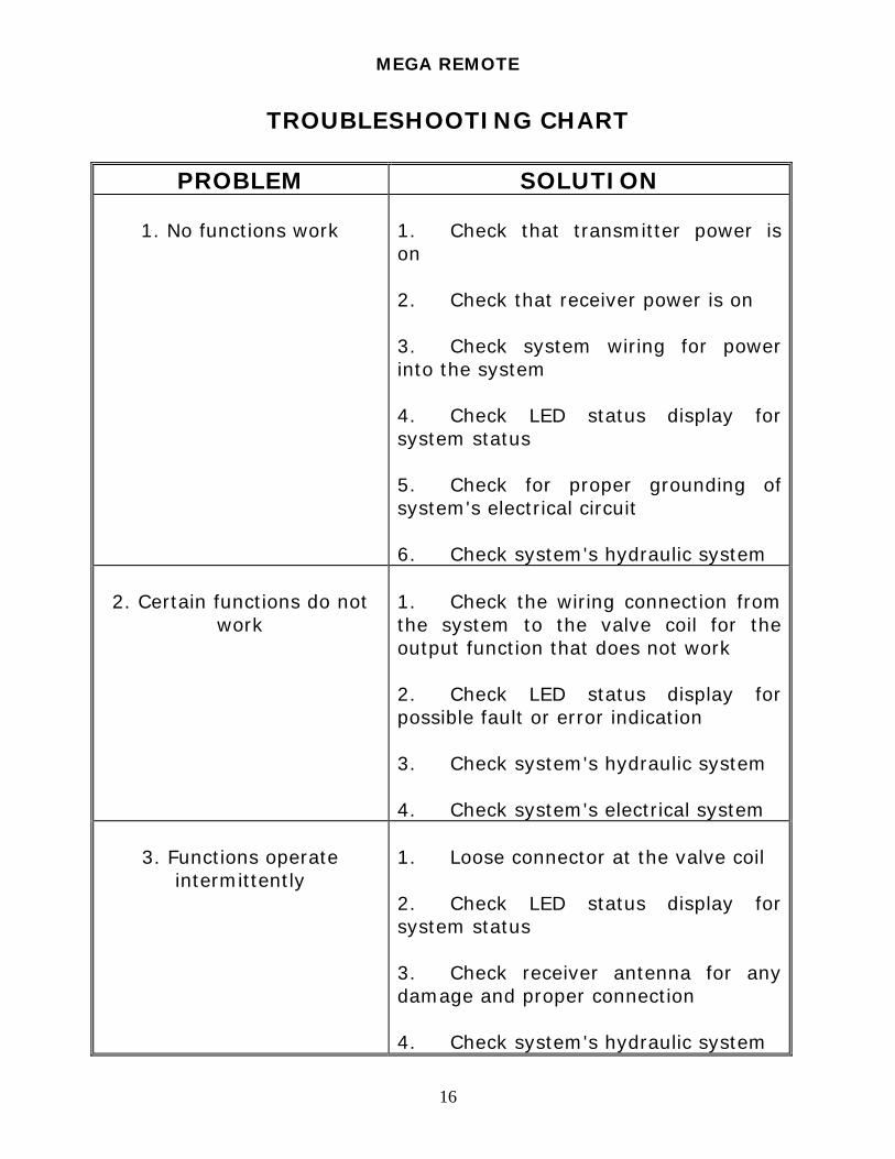
TROUBLESHOOTING CHART
PROBLEM SOLUTION
1. No functions work 1. Check that transmitter power is on 2. Check that receiver power is on 3. Check system wiring for power into the system 4. Check LED status display for system status 5. Check for proper grounding of system's electrical circuit 6. Check system's hydraulic system
2. Certain functions do not
work
1. Check the wiring connection from the system to the valve coil for the output function that does not work 2. Check LED status display for possible fault or error indication 3. Check system's hydraulic system 4. Check system's electrical system
3. Functions operate
intermittently
1. Loose connector at the valve coil 2. Check LED status display for system status 3. Check receiver antenna for any damage and proper connection 4. Check system's hydraulic system

MEGA REMOTE
17
ERROR CODES
Error code explanations: 1 Transmitter is off Transmitter went to sleep mode Interference in RF communication link 2 Transmitter and receiver are not synchronized 3 The RS-232 communication cable between the scale unit and
the receiver is damaged, disconnected, or the scale unit is off
4 System voltage is below 10.5V 5-16 Short or open load/coil on output

MEGA REMOTE
18
PARTS LIST
PART NUMBER
DESCRIPTION
3A2392A
RADIO TRANSMITTER
3A2393B
RADIO RECEIVER
There are no user-serviceable parts inside the transmitter or the receiver. Return the units for service. Note: For operation with negative ground systems only. WARNING: The MEGA REMOTE must be operated in compliance with all applicable safety regulations, rules, and practices. Failure to follow required safety practices may result in death or serious injury. The information, specifications, and illustrations in this manual are those in effect at the time of printing. We reserve the right to change specifications or design at any time without notice.

MEGA REMOTE
19
TRANSMITTER PICTORIAL
3.15
1.32
1.44
6.17
USES TWO (2) ALKALINE AABATTERIES
FRONT
REAR
CONVSWING
POWER
TIPSPOUT
UP
DOWN
REARDOOR
DN
UP
DOWN
FRONTDOOR
BOOM
UP
TARE
SCROLL
DNUP
UP
DOWN
CONVSTART
CONVSTOP

MEGA REMOTE
20
RECEIVER PICTORIAL
ERROR CODE NUMBER IS THE NUMBER OF RED LED PULSES BETWEEN EVERY PAUSE.
THE FOLLOWING CHART ASSISTS THE USER INTROUBLESHOOTING THE ELECTRICAL SYSTEM.
USER ASSIST DIAGNOSTIC
THERE ARE NO SERVICEABLE PARTS BEYOND THIS POINT. PLEASE CONTACT YOURSERVICE PERSONNEL FOR FURTHER ASSISTANCE.
RED
BLACK - GROUND
1/4" ROUND TERMINAL

MEGA REMOTE
21
SPECIFICATIONS
FCC ID: P4U-VRTS Industry Canada Certification Number: 4534A-VRTS EQUIPMENT CLASS: PART 15 SPREAD SPECTRUM TRANSMITTER TRANSMITTER Power .................................................. 2 x AA alkaline batteries
Operating temperature - Radio ........................... -20˚C to +85˚C
Storage temperature ....................................... -40˚C to +100˚C
RF Frequency ........................................................ 902-928 MHz
RF Transmit power (EIRP) ................................................ 33 mW
LCD display operating range (if equipped) .............. -20˚C to +70˚C
Vibration ................................................................ 3G to 200Hz
Shock ................................................................................ 50G
NEMA ................................................................................... 12
RECEIVER Power supply voltage ................................................... 9-30VDC
Operating temperature ...................................... -40˚C to +85˚C
Storage temperature ....................................... -40˚C to +100˚C
Outputs ................................................ 5.0A max each, sourcing
RF Frequency ........................................................ 902-928 MHz
Vibration ................................................................ 3G to 200Hz
Shock .............................................................................. 100G
NEMA ................................................................................... 4X

MEGA REMOTE
22
INSTRUCTION TO THE USER
This equipment has been tested and found to comply with the limits for a class B digital device, pursuant to part 15 of the FCC Rules. These limits are designed to provide reasonable protection against harmful interference in a residential installation. This equipment generates radio frequency energy and if not installed and used in accordance with the instructions, may cause harmful interference to radio communications. However, there is no guarantee that interference will not occur in a particular installation. If this equipment does cause harmful interference to radio or television reception, which can be determined by turning the equipment off and on, the user is encouraged to try to correct the interference by one or more of the following measures: * Reorient or relocate the receiving antenna. * Increase the separation between the equipment and receiver. * Connect the equipment into an outlet on a circuit different from that to which the receiver is connected. * Consult the dealer or an experienced radio/TV technician for help. This equipment has been certified to comply with the limits for a class B computing device, pursuant to FCC Rules. In order to maintain compliance with FCC regulations, shielded cables must be used with this equipment. Operation with non-approved equipment or unshielded cables is likely to result in interference to radio and TV reception. The user is cautioned that changes and modifications made to the equipment without the approval of manufacturer could void the user's authority to operate this equipment.