Meeting Agenda Five-Year Review of FAC Standards FiveYear Review... · i. Review directives related...
131
Meeting Agenda Five-Year Review of FAC Standards June 17, 2013 | 1-5 p.m. Eastern June 18, 2013 | 8 a.m.-5 p.m. Eastern June 19, 2013 | 8 a.m.-Noon Eastern NERC’s DC Office 1325 G Street NW, Suite 600 Washington, DC 20005 Dial-in: 866.740.1260 | Access Code: 6191629 | Security Code: 061713 Web Access: www.readytalk.com ; enter access code 6191629 Administrative 1. NERC Antitrust Compliance Guidelines, Public Announcement, Participant Conduct Policy, and Email List Policy* 2. Introductions 3. Meeting Logistics 4. Meeting Agenda and Objectives Agenda Items 1. Working Documents – Review and Discussion a. Standards Tracking Document* i. Review directives related to FAC-002 (referenced in tracking document; paragraphs 687 and 692 of FERC Order 693 ) ii. Note the addition of the link to a Compliance Analysis Report (CAR) for FAC-008 and FAC-009 (NEW) b. WECC White Papers on Proposed Changes to FAC-010 and FAC-011 (NEW)* c. Five-Year Review Template* d. Complete Set of FAC Reliability Standards* 2. Opportunities for Consolidation and/or Retirement – Discussion 3. Develop Draft Five-Year Review Team Recommendations – Discussion a. FAC-001-1
Transcript of Meeting Agenda Five-Year Review of FAC Standards FiveYear Review... · i. Review directives related...

Meeting Agenda Five-Year Review of FAC Standards June 17, 2013 | 1-5 p.m. Eastern June 18, 2013 | 8 a.m.-5 p.m. Eastern June 19, 2013 | 8 a.m.-Noon Eastern NERC’s DC Office 1325 G Street NW, Suite 600 Washington, DC 20005 Dial-in: 866.740.1260 | Access Code: 6191629 | Security Code: 061713 Web Access: www.readytalk.com; enter access code 6191629 Administrative
1. NERC Antitrust Compliance Guidelines, Public Announcement, Participant Conduct Policy, and Email List Policy*
2. Introductions
3. Meeting Logistics
4. Meeting Agenda and Objectives Agenda Items
1. Working Documents – Review and Discussion
a. Standards Tracking Document*
i. Review directives related to FAC-002 (referenced in tracking document; paragraphs 687 and 692 of FERC Order 693)
ii. Note the addition of the link to a Compliance Analysis Report (CAR) for FAC-008 and FAC-009 (NEW)
b. WECC White Papers on Proposed Changes to FAC-010 and FAC-011 (NEW)*
c. Five-Year Review Template*
d. Complete Set of FAC Reliability Standards*
2. Opportunities for Consolidation and/or Retirement – Discussion
3. Develop Draft Five-Year Review Team Recommendations – Discussion
a. FAC-001-1

Five-Year Review of FAC Standards 2
b. FAC-002-1
c. FAC-003-3
d. FAC-008-3
e. FAC-010-2.1
f. FAC-011-2
g. FAC-013-2
h. FAC-014-2
i. FAC-501-WECC-1
4. Informal Outreach – Discussion
a. Identification of opportunities for industry outreach
5. Next Steps – Review
a. Review/revise Action Plan*
i. Plan for refining recommendations
ii. Plan for posting
6. Informational Items – Review
a. FYRT Roster*
b. Meeting Notes for June 10, 2013 Conference Call*
7. Future Meeting Dates – Review
a. June 25, 2013, 9 a.m.-Noon Eastern, Conference Call
b. Conference call in July?
c. In-person meeting to review comments in September?
8. Adjourn
*Background materials included.

Antitrust Compliance Guidelines I. General It is NERC’s policy and practice to obey the antitrust laws and to avoid all conduct that unreasonably restrains competition. This policy requires the avoidance of any conduct that violates, or that might appear to violate, the antitrust laws. Among other things, the antitrust laws forbid any agreement between or among competitors regarding prices, availability of service, product design, terms of sale, division of markets, allocation of customers or any other activity that unreasonably restrains competition. It is the responsibility of every NERC participant and employee who may in any way affect NERC’s compliance with the antitrust laws to carry out this commitment. Antitrust laws are complex and subject to court interpretation that can vary over time and from one court to another. The purpose of these guidelines is to alert NERC participants and employees to potential antitrust problems and to set forth policies to be followed with respect to activities that may involve antitrust considerations. In some instances, the NERC policy contained in these guidelines is stricter than the applicable antitrust laws. Any NERC participant or employee who is uncertain about the legal ramifications of a particular course of conduct or who has doubts or concerns about whether NERC’s antitrust compliance policy is implicated in any situation should consult NERC’s General Counsel immediately. II. Prohibited Activities Participants in NERC activities (including those of its committees and subgroups) should refrain from the following when acting in their capacity as participants in NERC activities (e.g., at NERC meetings, conference calls and in informal discussions):
• Discussions involving pricing information, especially margin (profit) and internal cost information and participants’ expectations as to their future prices or internal costs.
• Discussions of a participant’s marketing strategies.
• Discussions regarding how customers and geographical areas are to be divided among competitors.
• Discussions concerning the exclusion of competitors from markets.
• Discussions concerning boycotting or group refusals to deal with competitors, vendors or suppliers.
NERC Antitrust Compliance Guidelines 2
• Any other matters that do not clearly fall within these guidelines should be reviewed with NERC’s General Counsel before being discussed.
III. Activities That Are Permitted From time to time decisions or actions of NERC (including those of its committees and subgroups) may have a negative impact on particular entities and thus in that sense adversely impact competition. Decisions and actions by NERC (including its committees and subgroups) should only be undertaken for the purpose of promoting and maintaining the reliability and adequacy of the bulk power system. If you do not have a legitimate purpose consistent with this objective for discussing a matter, please refrain from discussing the matter during NERC meetings and in other NERC-related communications. You should also ensure that NERC procedures, including those set forth in NERC’s Certificate of Incorporation, Bylaws, and Rules of Procedure are followed in conducting NERC business. In addition, all discussions in NERC meetings and other NERC-related communications should be within the scope of the mandate for or assignment to the particular NERC committee or subgroup, as well as within the scope of the published agenda for the meeting. No decisions should be made nor any actions taken in NERC activities for the purpose of giving an industry participant or group of participants a competitive advantage over other participants. In particular, decisions with respect to setting, revising, or assessing compliance with NERC reliability standards should not be influenced by anti-competitive motivations. Subject to the foregoing restrictions, participants in NERC activities may discuss:
• Reliability matters relating to the bulk power system, including operation and planning matters such as establishing or revising reliability standards, special operating procedures, operating transfer capabilities, and plans for new facilities.
• Matters relating to the impact of reliability standards for the bulk power system on electricity markets, and the impact of electricity market operations on the reliability of the bulk power system.
• Proposed filings or other communications with state or federal regulatory authorities or other governmental entities.
Matters relating to the internal governance, management and operation of NERC, such as nominations for vacant committee positions, budgeting and assessments, and employment matters; and procedural matters such as planning and scheduling meetings.

Public Announcements REMINDER FOR USE AT BEGINNING OF MEETINGS AND CONFERENCE CALLS THAT HAVE BEEN PUBLICLY NOTICED AND ARE OPEN TO THE PUBLIC Conference call version: Participants are reminded that this conference call is public. The access number was posted on the NERC website and widely distributed. Speakers on the call should keep in mind that the listening audience may include members of the press and representatives of various governmental authorities, in addition to the expected participation by industry stakeholders. Face-to-face meeting version: Participants are reminded that this meeting is public. Notice of the meeting was posted on the NERC website and widely distributed. Participants should keep in mind that the audience may include members of the press and representatives of various governmental authorities, in addition to the expected participation by industry stakeholders. For face-to-face meeting, with dial-in capability: Participants are reminded that this meeting is public. Notice of the meeting was posted on the NERC website and widely distributed. The notice included the number for dial-in participation. Participants should keep in mind that the audience may include members of the press and representatives of various governmental authorities, in addition to the expected participation by industry stakeholders.
Standards Development Process Participant Conduct Policy
I. General To ensure that the standards development process is conducted in a responsible, timely and efficient manner, it is essential to maintain a professional and constructive work environment for all participants. Participants include, but are not limited to, members of the standard drafting team and observers. Consistent with the NERC Rules of Procedure and the NERC Standard Processes Manual, participation in NERC’s Reliability Standards development balloting and approval processes is open to all entities materially affected by NERC’s Reliability Standards. In order to ensure the standards development process remains open and to facilitate the development of reliability standards in a timely manner, NERC has adopted the following Participant Conduct Policy for all participants in the standards development process. II. Participant Conduct Policy All participants in the standards development process must conduct themselves in a professional manner at all times. This policy includes in-person conduct and any communication, electronic or otherwise, made as a participant in the standards development process. Examples of unprofessional conduct include, but are not limited to, verbal altercations, use of abusive language, personal attacks or derogatory statements made against or directed at another participant, and frequent or patterned interruptions that disrupt the efficient conduct of a meeting or teleconference. III. Reasonable Restrictions in Participation If a participant does not comply with the Participant Conduct Policy, certain reasonable restrictions on participation in the standards development process may be imposed as described below. If a NERC Standards Developer determines, by his or her own observation or by complaint of another participant, that a participant’s behavior is disruptive to the orderly conduct of a meeting in progress, the NERC Standards Developer may remove the participant from a meeting. Removal by the NERC Standards Developer is limited solely to the meeting in progress and does not extend to any future meeting. Before a participant may be asked to leave the meeting, the NERC Standards Developer must first remind the participant of the obligation to conduct himself or herself in a professional manner and provide an opportunity for the participant to comply. If a participant is requested to leave a meeting by a NERC Standards Developer, the participant must cooperate fully with the request. Similarly, if a NERC Standards Developer determines, by his or her own observation or by complaint of another participant, that a participant’s behavior is disruptive to the orderly conduct of a

Standards Development Process Participant Conduct Policy 2
teleconference in progress, the NERC Standards Developer may request the participant to leave the teleconference. Removal by the NERC Standards Developer is limited solely to the teleconference in progress and does not extend to any future teleconference. Before a participant may be asked to leave the teleconference, the NERC Standards Developer must first remind the participant of the obligation to conduct himself or herself in a professional manner and provide an opportunity for the participant to comply. If a participant is requested to leave a teleconference by a NERC Standards Developer, the participant must cooperate fully with the request. Alternatively, the NERC Standards Developer may choose to terminate the teleconference. At any time, the NERC Director of Standards, or a designee, may impose a restriction on a participant from one or more future meetings or teleconferences, a restriction on the use of any NERC-administered list server or other communication list, or such other restriction as may be reasonably necessary to maintain the orderly conduct of the standards development process. Restrictions imposed by the Director of Standards, or a designee, must be approved by the NERC General Counsel, or a designee, prior to implementation to ensure that the restriction is not unreasonable. Once approved, the restriction is binding on the participant. A restricted participant may request removal of the restriction by submitting a request in writing to the Director of Standards. The restriction will be removed at the reasonable discretion of the Director of Standards or a designee. Any participant who has concerns about NERC’s Participant Conduct Policy may contact NERC’s General Counsel.

NERC Email List Policy NERC provides email lists, or “listservs,” to NERC committees, groups, and teams to facilitate sharing information about NERC activities; including balloting, committee, working group, and drafting team work, with interested parties. All emails sent to NERC listserv addresses must be limited to topics that are directly relevant to the listserv group’s assigned scope of work. NERC reserves the right to apply administrative restrictions to any listserv or its participants, without advance notice, to ensure that the resource is used in accordance with this and other NERC policies. Prohibited activities include using NERC‐provided listservs for any price‐fixing, division of markets, and/or other anti‐competitive behavior.1 Recipients and participants on NERC listservs may not utilize NERC listservs for their own private purposes. This may include announcements of a personal nature, sharing of files or attachments not directly relevant to the listserv group’s scope of responsibilities, and/or communication of personal views or opinions, unless those views are provided to advance the work of the listserv’s group. Use of NERC’s listservs is further subject to NERC’s Participant Conduct Policy for the Standards Development Process.
‐ Updated April 2013
1 Please see NERC’s Antitrust Compliance Guidelines for more information about prohibited antitrust and anti‐competitive behavior or practices. This policy is available at http://www.nerc.com/commondocs.php?cd=2

1
Standard Enforcement Date Review History Additional Notes FAC-001-0—Facility Connection Requirements
6/18/2007 Hasn’t been substantially reviewed. Project 2010-07: Generator Requirements at the Transmission Interface added GOs to the applicability but otherwise made no changes in FAC-001-1, which has been approved by the BOT (on 2/9/2012). FERC has issued a NOPR but has not yet approved the standard.
P81 COMMENTS: R1&R2: Requirement to document and publish facility connection requirements has no impact on reliability. It is purely a document that those considering to interconnect with a transmission entity may review as a reference. R1&R2: The requirement in FAC-001-0 to document and publish facility connection requirements has no impact on reliability. It is purely a document that those considering to interconnect with a transmission entity may review as a reference. Once an interconnection request is actually made with a transmission owner, the transmission owner performs the FAC-002-1 steady-state, short-circuit, and dynamics studies to determine the new interconnection’s impact on reliability. During the negotiation of an interconnection agreement the FAC-001-0 referenced material is agreed on and reduced to writing for purposes of constructing, maintaining and operating the interconnection facilities. Also, during the entire interconnection process, as FAC-002-1 provides for, the parties must coordinate and cooperate during the assessment of the reliability impact of the new interconnection facilities. Thus, FAC-001-0, at best, is a best practice or helpful initial guide to an entity considering interconnecting, but provides little, if any, meaningful value to reliability, especially when compared to the actual benefits to reliability via the FAC-002-1 studies, the execution of a negotiated agreement and the coordination of activities during constriction and operation of the new facilities. Accordingly, FAC-001-0 should be retired, and, if necessary, any requirements that protect reliability should be transferred to FAC-002-1 R3: Retirement of FAC-001-0 R3 should be considered in the next phase. There is an implied obligation for the TO to update its Facility connection requirements when they change. Additionally, a requirement to make them available to the Regional Entity and users of the transmission system is unnecessary. First, the Regional Entity could request them through the compliance monitoring process. Second, the TO will provide the Facility connection requirements to those with genuine interconnection requests because the TO will want its connection standards met. This requirement meets criterion B.4, B.7 and B.9. DIRECTIVES, INTERPRETATIONS, CANS:

2
This standard has no directives, interpretations, or CANs associated with it. COMPLIANCE/ENFORCEMENT NOTES: FAC-001 is one of the most frequently violated non-CIP standards. All the requirements in FAC-001-0 appear on the 2013 Actively Monitored List. (R2, R2.1, R2.1.1, R2.1.5, and R2.1.14 are Tier 1; R2.1.4 and R2.1.16 are Tier 2; R1 and its subparts, R2.1.1, R2.1.3, R2.1.6 through R2.1.13, R2.1.15, and R3 are Tier 3.)
FAC-002-1—Coordination of Plans for New Facilities
10/1/2011 1/13/2006: Removed duplication of RRO (errata). 8/5/210: Modified to address order 693 directives. Adopted by BOT. 2/7/2013: R2 approved by BOT for retirement under P81.
P81 COMMENTS: R1: FAC-002-1 R1 should be revised to reflect the NERC Functional Model because it assigns the requirements to the wrong functional entities. The Transmission Planner and Planning Coordinator are responsible for conducting the assessments for new Facilities. The requirement appears to be an attempt to require the GO, TO, DP, and LSE to coordinate with the TP and PC. However, the requirement actually defines what is required in the TP and PC assessments which unfortunately place these responsibilities on the GO, TO, DP and LSE. None of these functional entities have the capability to meet requirements such as performing dynamics studies. This requirement meets criterion B.8. R1: R1 can be removed. DIRECTIVES: There are two directives from Order 693 that apply to FAC-002-0. One directs that NERC consider a incorporating a reference to TPL-004-0 in FAC-002-0. The other directs that NERC consider the comments of various entities asking for clarification of R1:
• APPA requests that the Reliability Standard be clarified to state that the required assessment must be performed only by the transmission planner and the planning authority.
• Xcel requests that the Commission clarify that only one required assessment needs to be done when new facilities are added, and that all the listed entities should participate in that single assessment.
• FirstEnergy requests that NERC clarify what is considered a new facility and asks if, for example, up-rates should be included as new facilities.

3
• Six Cities requests that this Reliability Standard clarify that all applicable entities must make available data necessary for all other responsible entities to perform the required assessment.
• Six Cities also suggests that the transmission operator be added as an entity to which this Reliability Standard is applicable, at least from the perspective that it make necessary data available to all other entities responsible for assessment.
• TAPS believes that this Reliability Standard seems to assume that the LSE and distribution provider actively participate in planning of new facilities in the Bulk-Power System. TAPS states that very few LSEs or distribution providers have the expertise to perform the tasks outlined in this Reliability Standard and that these two entities provide only certain data regarding certain new facilities to some or all of the other entities identified in this Reliability Standard. TAPS therefore believes that it would be unreasonable to require LSEs to provide the transmission planning evaluations and assessments called for by R1.
• California Cogeneration believes that the Reliability Standard implies that generator owners will perform an independent assessment and if so, it believes that such task is impossible, since generators do not have the relevant information about the power system to perform such evaluations. California Cogeneration believes that the Reliability Standard should be clarified so that generator owners cooperate with and provide input to the assessment performed by the transmission operator and the balancing authority.
• FirstEnergy states that both MISO and PJM already have Large Generator Interconnection Procedures (LGIP) in place that provide a formal process that meets the requirements listed under R1, and asks that the Commission state that complying with the interconnection agreement and/or OATT satisfies this requirement.
• MISO states that their procedures for coordinating plans for new generation, transmission and end-user facilities includes modeling of normal system and contingency conditions.
INTERPRETATIONS AND CANS: This standard has no interpretations or CANs associated with it.

4
COMPLIANCE/ENFORCEMENT NOTES: All of the requirements in FAC-002-1 appear on the 2013 Actively Monitored List. (R1 and R1.3 are Tier 1; R1.1, R1.2, R1.4, and R1.5 are Tier 2.)
FAC-003-2—Transmission Vegetation Management
7/1/2014 4/4/2007: Effective date for the mostly errata changes in Version 1. 3/21/2013: Version 2 approved by FERC (first RBS standard to be approved). Additionally, Project 2010-07: Generator Requirements at the Transmission Interface added GOs to the applicability but otherwise made no changes in FAC-003-3, which has been approved by the BOT (on 2/9/2012). FERC has issued a NOPR but has not yet approved the standard.
We likely won’t need to touch this one; would probably pretty controversial if we did so. P81 COMMENTS: There were several P81 comments on FAC-003-1, but since FERC has already approved FAC-003-2, they are no longer relevant. DIRECTIVES, INTERPRETATIONS, CANS: This standard has no directives, interpretations, or CANs associated with it. COMPLIANCE/ENFORCEMENT NOTES: All of the requirements in FAC-003-1 (the currently enforceable version of the standard) appear on the 2013 Actively Monitored List. (R1 and its subparts and R2 are Tier 1; R3 and its subparts and R4 are Tier 2.)
FAC-008-3—Facility Ratings
1/1/2013 3/16/2007: Version 1 approved by FERC. 5/12/2010: Version 2 adopted by BOT (merged FAC-008-1 and FAC-009-1 under Project 2009-06 and addressed 693 directives). 11/17/2011: FERC approved FAC-008-3, which added R8 and addressed an additional 693 directive. 5/17/2012: FERC ordered that the VRF for R2 be changed from Lower to Medium. 2/7/2013: R4 and R5 approved by BOT for
P81 COMMENTS: There were several P81 comments on FAC-008-1, but since FERC has already approved FAC-008-3, they are no longer relevant. This standard has no interpretations associated with it. DIRECTIVES AND INTERPRETATIONS: This standard has no directives or interpretations associated with it. CANs: CAN-0009 is associated with FAC-008-1 and FAC-009-1. It provides instruction for assessing compliance with FAC-008-1 R1 and FAC-009-1 R1 when an entity’s constructed Facilities do not match its design specification and does appear to still apply to the requirements in FAC-008-3. CAN-0018 is associated with FAC-008, and does appear to still apply to FAC-008-3, though the CAN was originally developed for FAC-008-1. IN CAN-0018, NERC compliance says that “terminal equipment” (referenced in R2.4.1 and

5
retirement under P81. R3.4.1) refers to wave traps, current transformers, disconnect switches, breakers, primary fuses, and any piece of series-connected equipment that comprises a Facility and that could have the most limited applicable Equipment Rating. COMPLIANCE/ENFORCEMENT NOTES: FAC-008 and FAC-009 are among the most frequently violated non-CIP standards. A Compliance Analysis Report was developed in 2010 to “provide information on compliance including reasons for violations and identification of process enhancements and lessons learned to assist Registered Entities in improving compliance and thus enhancing reliability.” Some of the FAC-008-3 requirements appear on the Actively Monitored List. (R6 and R7 are Tier 1; R1, R2, and R3 and their subparts are Tier 2; and R8 is Tier 3. R4 and R5 are not on the list.)
FAC-010-2.1—System Operating Limits Methodology for the Planning Horizon
4/19/2010 11/1/2006: Version 1 adopted by BOT. 4/19/2010: FERC approved the mostly errata changes in Version 2.1 (updates to dates, definitions, numbering convention, VSLs, typos). 2/7/2013: R5 approved by BOT for retirement under P81.
P81 COMMENTS, DIRECTIVES, INTERPRETATIONS, CANS: This standard has no P81 comments, directives, interpretations, or CANs associated with it. COMPLIANCE/ENFORCEMENT NOTES: FAC-010-2.1 does not have any requirements on the 2013 Actively Monitored List.
FAC-011-2—System Operating Limits Methodology for the Operations Horizon
4/29/2009 11/1/2006: Version 1 adopted by BOT. 4/19/2010: FERC approved the mostly errata changes in Version 2 (updates to dates, definitions, numbering convention, VSLs, typos). 2/7/2013: R5 approved by BOT for retirement under P81.
P81 COMMENTS, DIRECTIVES, INTERPRETATIONS, CANS: This standard has no P81 comments, directives, interpretations, or CANs associated with it. COMPLIANCE/ENFORCEMENT NOTES: FAC-011-2 does not have any requirements on the 2013 Actively Monitored List.
FAC-013-2—Assessment of Transfer Capability for the Near-term
4/1/2013 8/1/2005: Errata changes made. 11/17/2011: FERC approved
P81 COMMENTS: R5: Remove ‘However, if a functional entity that has a reliability related need for the results of the annual assessment of the Transfer Capabilities makes a

6
Transmission Planning Horizon
Version 2. 5/17/2012: FERC ordered that the VRFs for R1 and R4 be changed from Lower to Medium; corrected High and Severe VSL language for R1. 2/7/2013: R3 approved by BOT for retirement under P81.
written request for such an assessment after the completion of the assessment, the Planning Coordinator shall make the documented Transfer Capability assessment results available to that entity within 45 calendar days of receipt of the request’ R6: These are all reporting requirements; they do not aid reliability from an immediate time perspective. If the Regional Entity desires to review information for purposes of monitoring reliability or assessing risk, the information should be collected via vehicles other than the Reliability Standards R6: Remove ‘If a recipient of a documented Transfer Capability assessment requests data to support the assessment results, the Planning Coordinator shall provide such data to that entity within 45 calendar days of receipt of the request. The provision of such data shall be subject to the legal and regulatory obligations of the Planning Coordinator’s area regarding the disclosure of confidential and/or sensitive information’ R6: There is no direct nexus between reporting out of information to an entity or Regional Entity and protecting reliability. If the Regional Entity desires to review information for purposes of monitoring reliability or assessing risk, the information should be collected via vehicles other than the Reliability Standards. There were also several P81 comments on FAC-013-1, but since FAC-013-2 is already enforceable, they are no longer relevant. DIRECTIVES, INTERPRETATIONS, CANS: This standard has no directives, interpretations, or CANs associated with it. COMPLIANCE/ENFORCEMENT NOTES: FAC-013-2 does not have any requirements on the 2013 Actively Monitored List.
FAC-014-2—Establish and Communicate System Operating Limits
4/29/2009 11/1/2006: Version 1 adopted by BOT. 4/29/2009: FERC approved Version 2.
This standard has no interpretations, P81 comments associated with it. COMPLIANCE/ENFORCEMENT NOTES: FAC-014-2 does not have any requirements on the 2013 Actively Monitored List.

7
FAC-501-WECC-1—Transmission Maintenance
7/1/2011 4/21/2011: FERC approved Version 1.
P81 COMMENTS, DIRECTIVES, INTERPRETATIONS, CANS: This standard has no P81 comments, directives, interpretations, or CANs associated with it. COMPLIANCE/ENFORCEMENT NOTES: FAC-501-WECC-1 does not have any requirements on the 2013 Actively Monitored List.
White Paper
On
Proposed Changes to FAC010 Western Interconnection Regional Differences
February 6, 2013
Summary Both NERC Reliability Standards FAC‐010 and FAC‐011 contain Regional Differences which apply
to Western Interconnection. FAC‐010 applies to the Planning Horizon and FAC‐011 applies to
the Operations Horizon. The purpose of this document is to provide background and justification
for proposing changes to the FAC‐010 Western Interconnection regional differences. A separate
white paper is being prepared to address issues regarding FAC‐011 Western Interconnection
regional differences.
Background When the FAC‐010 and FAC‐011 standards were originally created in 2007, WECC had regional
planning criteria in place which was a combination of NERC planning standards and additional
WECC reliability criteria. When the FAC‐010 and FAC‐011 standards were developed, WECC
added regional differences to these standards to include the additional planning criteria, which
were in effect at that time. Since then, WECC has revised its planning criteria significantly
making some of the requirements in the regional differences obsolete. This white paper has
been assembled to review each of the Western Interconnection regional difference
requirements to determine if they are relevant today, and to propose changes or elimination, as
appropriate.
Introduction Prior to 2007, WECC’s planning criteria were called NERC/WECC Planning Standards, which
included WECC requirements in addition to NERC standards. The additional WECC criteria did
not apply to internal systems (internal to the Planning Authority’s system). The following is a
quote from the NERC/WECC Planning Standards.
The NERC standards and associated Table I are applicable to all systems, without
distinction between internal and external systems. Unless otherwise stated, WECC
standards and the associated WECC Disturbance‐Performance Table of Allowable Effects
on Other Systems are not applicable to internal systems.

When the NERC mandatory standards became effective in 2007, some of the WECC criteria were
added as regional differences to the NERC mandatory standards. FAC‐010 and FAC‐011 are two
such standards where several additional regional requirements were added. The regional
differences are based on obsolete WECC planning criteria extracted from the document titled
“Reliability Criteria Part I – WECC NERC/Planning Standards”, dated April 2005. WECC’s
Reliability Subcommittee (RS) has had the responsibility to develop criteria to be used by WECC
members. Following the advent of NERC standards in 2007, the WECC RS extracted the
additional WECC requirements into a separate document. This document had an effective date
of April 18, 2008, and is titled:
TPL – (001 thru 004) – WECC – 1 – CR ─ System Performance Criteria
WECC modified this document through the WECC standards process (Project WECC‐0071). The
existing WECC reliability criteria came into effect on April 1, 2012. This document is now
designated as:
TPL‐001‐WECC‐CRT‐2 System Performance Criterion (now TPL‐001‐WECC‐RBP‐3)
One of the most significant changes in the latest document is the definition of Adjacent
Transmission Circuits. RS’s intention is to apply the Adjacent Transmission Circuits definition to
all standards and criteria when adjacent circuits or Adjacent Transmission Circuits are
referenced. Furthermore, as defined in the above WECC TPL criteria, the Adjacent Transmission
Circuits criteria application is limited to the following:
• Applies to circuits 300 kV and higher.
• Does not apply to Adjacent Transmission Circuits that share a common right‐of‐way for
a total of three miles or less, including – but not limited to – substation entrances, pinch
points, and river crossings.
• Applies only to effects on facilities external to a Transmission Planner’s area.
There are two significant issues with the WECC regional differences in the FAC‐010 standard that
need to be resolved.
Issue # 1: Regional Difference Requirement E.1.1.5 of the current FAC‐010‐2.1 standard applies to
adjacent circuits that are Bulk Electric System (BES) elements, that are not restricted by voltage
levels, and that have exceptions for 5 towers for each substation entrance or exit rather than 3
miles common right of way. Thus, there are conflicts and ambiguities between existing WECC
criteria and existing WECC regional differences in the NERC standards.
Issue #2: Regional Difference Requirement E.1.1.1 of the current FAC‐010‐2.1 standard requires studies
simulating the simultaneous permanent phase‐to‐ground faults on different phases of each of
two adjacent transmission circuits on a multiple circuit tower. The common stability programs

in use today do not have the ability to simulate a simultaneous ground fault on different phases
of two different circuits. Also, no reliability benefit is obtained by simulating the fault on two
different phases of two transmission circuits.
Therefore, the WECC RS concludes that the regional differences in the FAC‐010 NERC standard need to be updated to coordinate with today’s standards and criteria. To achieve this update, the RS intends to issue a SAR (Standard Authorization Request). However, RS recommends that rather than limiting the scope of the SAR to the above issues, the SAR should examine all requirements of the regional differences and suggest modification or elimination as technically justified.
Below, each requirement of the regional differences is stated and then examined in the
sequence that it appears in the standard. The examination of each regional difference includes
a technical discussion of its requirement and a recommendation of whether it should be
retained as‐is, modified as‐described, or eliminated entirely. To summarize, WECC RS finds most
of the Western Interconnection regional difference requirements in NERC Reliability standard
FAC‐010 to be redundant to various existing NERC reliability requirements, and therefore,
unnecessary as regional differences. For this reason and others reasons provided below, the
WECC RS recommends that all of the Western Interconnection regional difference requirements
in NERC Reliability Standard FAC‐010 be reviewed and if justified, eliminated.
NERC Standard FAC0102.1
E. Regional Differences As governed by the requirements of Requirements R2, R2.5 and R2.6, starting with all Facilities in service, the following Interconnection‐wide Regional Difference shall be applicable in the Western Interconnection and shall require the evaluation of the following multiple Facility Contingencies when establishing SOLs: R2. The Planning Authority’s SOL Methodology shall include a requirement that SOLs provide BES performance consistent with the following:
R2.5. Starting with all Facilities in service and following any of the multiple Contingencies identified in Reliability Standard TPL‐003 the system shall demonstrate transient, dynamic and voltage stability; all Facilities shall be operating within their Facility Ratings and within their thermal, voltage and stability limits; and Cascading or uncontrolled separation shall not occur.
R2.6. In determining the system’s response to any of the multiple Contingencies, identified in Reliability Standard TPL‐003, in addition to the actions identified in R2.3.1 and R2.3.2, the following shall be acceptable:
R2.6.1. Planned or controlled interruption of electric supply to customers (load shedding), the planned removal from service of certain

generators, and/or the curtailment of contracted Firm (non‐recallable reserved) electric power Transfers.
Thus, the WECC regional differences extend Requirements R2.5 and R2.6. Requirements R2.5 and R2.6 address a process for developing SOLs and the WECC regional differences direct the Planning Authority (now Planning Coordinator) to account for these regional differences in developing a methodology. Each regional difference is first stated as is and is followed by a discussion and a recommendation. Requirement E1.1.1: Simultaneous permanent phase to ground Faults on different phases of each of the two adjacent transmission circuits on a multiple circuit tower, with Normal Clearing. If multiple circuit towers are used only for station entrances and exit purposes, and if they do not exceed five towers at each station, then this condition is an acceptable risk and therefore can be excluded.
Discussion: The common stability programs in use today do not have the ability to simulate a simultaneous ground fault on different phases of two different circuits. Also, no reliability benefit is obtained by simulating a single phase‐to‐ground fault on two different phases of two transmission circuits. There has not been any study in the past which simulated such a scenario, and it is not realistic to study the system assuming two faults occur at the same time resulting in a common mode simultaneous contingency. As such there is no technical justification for such a requirement. In addition, this event is addressed in NERC Reliability Standard TPL‐003‐0a (Table I) Category C‐5. Having regional difference duplicate that portion of TPL‐003‐0a to address the same system condition is redundant and unnecessary. Recommendation: RS recommends the elimination of the regional difference in E1.1.1. Requirement E1.1.2: A permanent phase to ground Fault on any generator, transmission circuit, transformer, or bus section with Delayed Fault Clearing except for bus sectionalizing breakers or bus‐tie‐breakers as addressed in E1.1.7.
Discussion: This requirement is addressed in NERC Reliability Standard TPL‐003‐0a (Table I) Category C‐6, 7, 8, and 9 contingencies. Having this regional difference duplicate that portion of TPL‐003‐0a to address the same system condition is redundant and unnecessary. Recommendation: RS recommends the elimination of the regional difference in E1.1.2. Requirement E1.1.3: Simultaneous permanent loss of both poles of a direct current bipolar Facility without an alternating current fault.

Discussion: This requirement is addressed in NERC Reliability Standard TPL‐003‐0a (Table I) Category C‐4 contingency. Having this regional difference duplicate that portion of TPL‐003‐0a to address the same system condition is redundant and unnecessary. Recommendation: RS recommends the elimination of the regional difference in E1.1.3. Requirement E1.1.4: The failure of a circuit breaker associated with a Special Protection System (SPS) to operate when required following the loss of element without a fault; or a permanent phase to ground Fault, with Normal Clearing, or any transmission circuit, transformer or bus section.
Discussion: This requirement is addressed in NERC Reliability Standard PRC‐012‐0 R1.3, which requires that failure of a single component does not prevent the interconnected system from meeting required performance in the TPL Reliability Standards. It is also addressed in NERC Reliability Standard TPL‐003‐0a (Table I) Category C‐2, 6, 7, 8, and 9 contingencies, which specifies system performance requirements for breaker failure. Having this regional difference duplicate those portions of PRC‐012‐0 and TPL‐003‐0a to address the same system condition is redundant and unnecessary. Recommendation: RS recommends the elimination of the regional difference in E1.1.4. Requirement E1.1.5: A non‐three phase Fault with Normal Clearing on common mode Contingency of two adjacent circuits on separate towers unless the event frequency is determined to be less than one in 30 years.
Discussion: Requirement E1.1.5 uses the term “adjacent circuits” but the term is not defined in the NERC
Glossary. WECC recently defined this term in relation to its application for this requirement. WECC’s intention is to apply the Adjacent Transmission Circuits definition consistently to all
standards and criteria when ‘adjacent circuits’ or ‘Adjacent Transmission Circuits’ are
referenced. Furthermore, as defined in the WECC criteria document (TPL‐001‐WECC‐CRT‐2 System Performance Criterion), the adjacent circuit criteria application is limited to the
following:
• Applies to circuits 300 kV and higher.
• Does not apply to Adjacent Transmission Circuits that share a common right‐of‐way for
a total of three miles or less, including – but not limited to – substation entrances, pinch
points, and river crossings.
• Applies only to effects on facilities external to a Transmission Planner area.

Requirement E1.1.5[1] extends the requirement of NERC Reliability Standard TPL‐003a (Table I)
Category C‐5 contingency to adjacent circuits on separate structures, if they are operated at
300kV or higher and their centerlines are 250 feet or less in distance (certain other limitations
also apply). At the time this regional difference requirement was developed, it was believed
that the rate of common mode outages of adjacent circuits on separate structures was similar to
that of any two circuits of a multiple circuit towerline (covered by Category C‐5). As such, it
made sense to apply the same performance criteria to both classes of contingencies. However,
actual performance data for 230kV and above transmission lines in the Western Interconnection
indicate that the average outage rate per 100 miles of line is actually less than one‐half the rate
for circuits on common structures as shown in Table 1. Further, the actual outage rate for
circuits on common right‐of‐way but on separate structures is less than that for any two circuits
not on a common right‐of‐way or structure. The latter contingency is covered by NERC
Reliability Standard TPL‐003a (Table I) Category C‐3 contingency. Since Requirement E1.1.5 does
not demonstrate an additional reliability performance requirement in addition to the
contingencies covered by Category C‐3, it can be deleted without adversely impacting the
reliability of the Bulk Electric System.
Table 1: Outage Comparison of Circuits on Common ROW and/or Structures when 2 or more circuits went
out of service.
Table 1 Western
Interconnection Average Data 2008‐2011
Circuits on Common Structure
Circuits on Common Right‐of‐Way Separate Structures
Circuits not on Common ROW or
Structure
Transmission Miles 8,769 15,088 51,113
Number of Events 25.3
20.5 99.8
No. of Outages/ 100 miles of line
0.288 0.136 0.195
Recommendation: RS recommends the review of the regional difference in E1.1.5. If this is not eliminated then E1.1.5 must be modified to be consistent with the definition1 and intent of the adjacent circuit definition2.
[1] A non‐three phase Fault with Normal Clearing on common mode Contingency of two adjacent circuits on separate towers unless the event frequency is determined to be less than one in thirty years.
1 WECC Definition of Adjacent Transmission Circuits: Adjacent Transmission Circuits are two transmission circuits with separation between their center lines less than 250 feet at the point of separation with no Bulk Electric System circuit between them. Transmission circuits that cross, but are otherwise separated by 250 feet or more between their centerlines, are not Adjacent Transmission Circuits.
2 Applicable to only Adjacent Transmission Circuits where both circuits are greater than or equal to 300 kV. Only applies to effects on facilities external to a Transmission Planner area. Not applicable to Adjacent

Requirement E1.1.6: A common mode outage of two generating units connected to the same switchyard, not otherwise addressed by FAC‐010.
Discussion: The interpretation of this requirement is confusing where there is no known substation common mode outage between the units, yet planning studies include a two unit outage contingency. If the intention of the criteria is to include two units in the same plant connected to the same switchyard independent of any common mode outage, then the requirements should be revised to reflect that. It should be determined if there is any reliability benefit for conducting this analysis. Recommendation: RS recommends the review of the regional difference in E1.1.6. If this is not eliminated, then RS recommends the modification as stated above to reflect that two units in the same plant, irrespective of whether there is a common outage mode, shall not cause cascading. Requirement E1.1.7: The loss of multiple bus sections as a result of failure or delayed clearing of a bus tie or a bus sectionalizing breaker to clear a permanent Phase to Ground Fault.
Discussion: This requirement is addressed in NERC Reliability Standard TPL‐003‐0a (Table I) Category C‐9 contingency. Having this regional difference duplicate that portion of TPL‐003‐0a to address the same system condition is redundant and unnecessary. Recommendation: RS recommends the elimination of the regional difference in E1.1.7. Requirement E1.2: SOLs shall be established such that for multiple Facility Contingencies in E1.1.1 through E1.1.5 operation within the SOL shall provide system performance consistent with the following:
1.2.1 All Facilities are operating within their applicable Post‐Contingency thermal, frequency and voltage limits. 1.2.2 Cascading does not occur. 1.2.3 Uncontrolled separation of the system does not occur. 1.2.4 The system demonstrates transient, dynamic and voltage stability. 1.2.5 Depending on system design and expected system impacts, the controlled interruption of electric supply to customers (load shedding), the planned removal from service of certain generators, and/or the curtailment of contracted firm (non‐recallable reserved) electric power transfers may be necessary to maintain the overall security of the interconnected transmission systems.
Transmission Circuits that share a common right‐of‐way for a total of three miles or less, including – but not limited to – substation entrances, pinch points, and river crossings.

1.2.6 Interruption of firm transfer, Load or system reconfiguration is permitted through manual or automatic control or protection actions. 1.2.7 To prepare for the next Contingency, system adjustments are permitted, including changes to generation, Load and the transmission system topology when determining limits.
Discussion: This requirement is already addressed in Requirements R2.5 and R2.6 of NERC Reliability Standard FAC‐010‐2.1. Having this regional difference that duplicates the same system condition as portions of FAC‐010‐2.1 is redundant and unnecessary. Recommendation: RS recommends the elimination of the regional difference in E1.2. Requirement E1.3: SOLs shall be established such that for multiple Facility Contingencies in E1.1.6 through E1.1.7 operation within the SOL shall provide system performance consistent with the following with respect to impacts on other systems:
1.3.1 Cascading does not occur.
Discussion: This requirement is already addressed in Requirements R2.5 and R2.6 of NERC Reliability Standard FAC‐010‐2.1. Having this regional difference duplicate the same system condition as portions of FAC‐010‐2.1 is redundant and unnecessary. Recommendation: RS recommends the elimination of the regional difference in E1.3. Requirement E1.4: The Western Interconnection may make changes (performance category adjustments) to the Contingencies required to be studied and/or the required responses to Contingencies for specific facilities based on actual system performance and robust design. Such changes will apply in determining SOLs.
Discussion: Because this regional difference addresses category adjustments only within the WECC criteria
and E1.1.5, it is not clear and is unnecessary. Requirement E1.4 is not applicable to one of the
specific entities identified in the NERC Reliability Functional Model. Further, it does not add any
system performance reliability in addition to the existing requirements in NERC Reliability
Standards TPL‐001‐0.1 through TPL‐004‐0.
Recommendation: RS recommends the elimination of the regional difference in E1.4.

White Paper
On
Proposed Changes to FAC011 Western Interconnection Regional Differences
February 6, 2013
Summary
Both NERC Reliability Standards FAC‐010 and FAC‐011 contain Regional Differences which apply to
Western Interconnection. FAC‐010 applies to the Planning Horizon and FAC‐011 applies to the
Operations Horizon. The purpose of this document is to provide background and justification for
proposing changes to the FAC‐011 Western Interconnection regional differences. A separate white
paper is being prepared to address issues regarding FAC‐010 Western Interconnection regional
differences.
Background
When the FAC‐010 and FAC‐011 standards were originally created in 2007, WECC had regional planning
criteria in place which was a combination of NERC planning standards and additional WECC reliability
criteria. When the FAC‐010 and FAC‐011 standards were developed, WECC added regional differences to
these standards to include the additional planning criteria, which were in effect at that time. Since then,
WECC has revised its planning criteria significantly making some of the requirements in the regional
differences obsolete. This white paper has been assembled to make a recommendation for the purpose
of modification or elimination of the Western Interconnection regional difference in FAC‐011‐2, as
appropriate.
NERC Standard FAC0112
E. Regional Difference
The purpose of the NERC Standard FAC‐011‐2 is to establish and document a methodology for use in developing System Operating Limits (SOL) in the Operations Horizon, as governed by the requirements of Requirements R3 and R3.3:
R3. The Reliability Coordinator’s methodology for determining SOLs, shall include, as a minimum, a description of the following, along with any reliability margins applied for each:

R3.3. A process for determining which of the stability limits associated with the list of multiple contingencies (provided by the Planning Authority in accordance with FAC‐014 Requirement 6) are applicable for use in the operating horizon given the actual or expected system conditions.
R3.3.1. This process shall address the need to modify these limits, to modify the list of limits, and to modify the list of associated multiple contingencies.
Although the intent of the Regional Difference is to specify additional multiple Facility Contingencies that apply to the Western Interconnection, NERC Requirement R3.3 states the list of multiple contingencies is provided by the Planning Authority in accordance with FAC‐014 Requirement R6:
R6. The Planning Authority shall identify the subset of multiple contingencies (if any), from Reliability Standard TPL‐003 which results in stability limits.
R6.1. The Planning Authority shall provide this list of multiple contingencies and the associated stability limits to the Reliability Coordinators that monitor the facilities associated with these contingencies and limits.
R6.2. If the Planning Authority does not identify any stability‐related multiple contingencies, the Planning Authority shall so notify the Reliability Coordinator.
Discussion
The list of multiple contingencies identified by the Planning Authority is developed in accordance with Requirements 2.5 and 2.6 in Standard FAC‐010‐2.1, System Operating Limits Methodology for the Planning Horizon. Since the list of multiple Contingencies is provided by the Planning Authority to meet Requirement 3.3 in Standard FAC‐011‐2, it is therefore concluded that the WECC Regional Difference in FAC‐011‐2 is irrelevant and not necessary. In other words, the regional differences in FAC‐011‐2 are not used to develop additional contingencies to the list of multiple Contingencies already required to be studied. Therefore, all of the Western Interconnection regional difference in FAC‐011‐2 should be eliminated.
All of the requirements in the Western Interconnection regional differences in FAC‐010‐2.1 and FAC ‐011‐2 are the same. In addition as referenced in the WECC‐010 White Paper, WECC RS finds most of the Western Interconnection regional difference requirements in NERC Reliability standard FAC‐010 to be redundant to various existing NERC reliability requirements; and therefore, is recommending the requirements to be reviewed and if justified be eliminated.
Recommendation: RS recommends the elimination of the Regional Differences applicable to WECC in Standard FAC‐011‐2.

Five-Year Review Template Updated February 26, 2012 Introduction NERC has an obligation to conduct a five-year review of each Reliability Standard developed through NERC’s American National Standards Institute-accredited Reliability Standards development process.1
The Reliability Standard identified below is due for a five-year review. Your review team should use the background information and the questions below, along with any associated worksheets or reference documents, to guide a comprehensive review that results in a recommendation that the Reliability Standard should be (1) affirmed as is (i.e., no changes needed); (2) revised (which may include revising or retiring one or more requirements); or (3) withdrawn. If the team recommends a revision to the Reliability Standard, it should also submit a draft Standard Authorization Request (SAR) outlining the proposed scope and technical justification for the revision.
A completed five-year review template and any associated documentation should be submitted by email to Laura Hussey, Director of Standards Development at [email protected].
Applicable Reliability Standard:
Team Members (include name, organization, phone number, and email address):
1. 2. 3. 4. 5. 6. 7. 8.
Date Review Completed:
1 NERC Standard Processes Manual, posted at http://www.nerc.com/files/Appendix_3A_Standard_Processes_Manual_20110825.pdf, at page 41.
Five-Year Review Template DRAFT 2
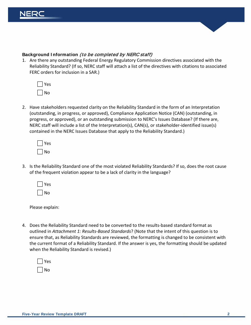
Background Information (to be completed by NERC staff) 1. Are there any outstanding Federal Energy Regulatory Commission directives associated with the
Reliability Standard? (If so, NERC staff will attach a list of the directives with citations to associated FERC orders for inclusion in a SAR.)
Yes
No
2. Have stakeholders requested clarity on the Reliability Standard in the form of an Interpretation
(outstanding, in progress, or approved), Compliance Application Notice (CAN) (outstanding, in progress, or approved), or an outstanding submission to NERC’s Issues Database? (If there are, NERC staff will include a list of the Interpretation(s), CAN(s), or stakeholder-identified issue(s) contained in the NERC Issues Database that apply to the Reliability Standard.)
Yes
No
3. Is the Reliability Standard one of the most violated Reliability Standards? If so, does the root cause
of the frequent violation appear to be a lack of clarity in the language?
Yes
No
Please explain:
4. Does the Reliability Standard need to be converted to the results-based standard format as outlined in Attachment 1: Results-Based Standards? (Note that the intent of this question is to ensure that, as Reliability Standards are reviewed, the formatting is changed to be consistent with the current format of a Reliability Standard. If the answer is yes, the formatting should be updated when the Reliability Standard is revised.)
Yes
No
Five-Year Review Template DRAFT 3
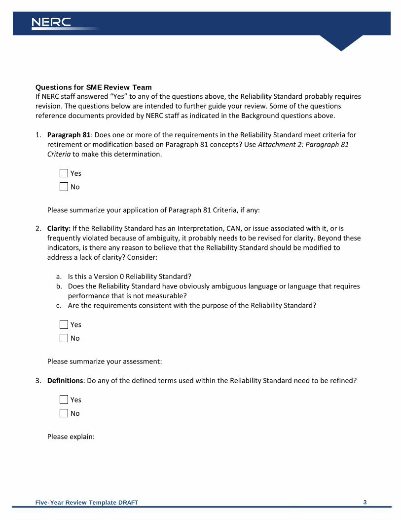
Questions for SME Review Team If NERC staff answered “Yes” to any of the questions above, the Reliability Standard probably requires revision. The questions below are intended to further guide your review. Some of the questions reference documents provided by NERC staff as indicated in the Background questions above. 1. Paragraph 81: Does one or more of the requirements in the Reliability Standard meet criteria for
retirement or modification based on Paragraph 81 concepts? Use Attachment 2: Paragraph 81 Criteria to make this determination.
Yes
No
Please summarize your application of Paragraph 81 Criteria, if any:
2. Clarity: If the Reliability Standard has an Interpretation, CAN, or issue associated with it, or is
frequently violated because of ambiguity, it probably needs to be revised for clarity. Beyond these indicators, is there any reason to believe that the Reliability Standard should be modified to address a lack of clarity? Consider:
a. Is this a Version 0 Reliability Standard? b. Does the Reliability Standard have obviously ambiguous language or language that requires
performance that is not measurable? c. Are the requirements consistent with the purpose of the Reliability Standard?
Yes
No
Please summarize your assessment:
3. Definitions: Do any of the defined terms used within the Reliability Standard need to be refined?
Yes
No
Please explain:

Five-Year Review Template DRAFT 4
4. Compliance Elements: Are the compliance elements associated with the requirements (Measures, Data Retention, VRFs, and VSLs) consistent with the direction of the Reliability Assurance Initiative and FERC and NERC guidelines? If you answered “No,” please identify which elements require revision, and why:
Yes
No
5. Consistency with Other Reliability Standards: Does the Reliability Standard need to be revised for
formatting and language consistency among requirements within the Reliability Standard or consistency with other Reliability Standards? If you answered “Yes,” please describe the changes needed to achieve formatting and language consistency:
Yes
No
6. Changes in Technology, System Conditions, or other Factors: Does the Reliability Standard need to be revised to account for changes in technology, system conditions, or other factors? If you answered “Yes,” please describe the changes and specifically what the potential impact is to reliability if the Reliability Standard is not revised:
Yes
No
7. Consideration of Generator Interconnection Facilities: Is responsibility for generator interconnection Facilities appropriately accounted for in the Reliability Standard?
Yes No
Guiding Questions: If the Reliability Standard is applicable to GOs/GOPs, is there any ambiguity about the inclusion of generator interconnection Facilities? (If generation interconnection Facilities could be perceived to be excluded, specific language referencing the Facilities should be introduced in the Reliability Standard.)

Five-Year Review Template DRAFT 5
If the Reliability Standard is not applicable to GOs/GOPs, is there a reliability-related need for treating generator interconnection Facilities as transmission lines for the purposes of this Reliability Standard? (If so, GOs and GOPs that own or operate relevant generator interconnection Facilities should be explicit in the applicability section of the Reliability Standard.)

Five-Year Review Template DRAFT 6
Recommendation The answers to the questions above, along with a preliminary recommendation of the SMEs conducting the review of the Reliability Standard, will be posted for a 45-day informal comment period, and the comments publicly posted. The SMEs will review the comments to evaluate whether to modify their initial recommendation, and will document the final recommendation which will be presented to the Standards Committee. Preliminary Recommendation (to be completed by the SME team after its review and prior to posting the results of the review for industry comment):
AFFIRM
REVISE
RETIRE
Technical Justification (If the SME team recommends that the Reliability Standard be revised, a draft SAR may be included and the technical justification included in the SAR):
Preliminary Recommendation posted for industry comment (date):
Final Recommendation (to be completed by the SME team after it has reviewed industry comments on the preliminary recommendation):
AFFIRM (This should only be checked if there are no outstanding directives, interpretations
or issues identified by stakeholders.)
REVISE
RETIRE
Technical Justification (If the SME team recommends that the Reliability Standard be revised, a draft SAR may be included and the technical justification included in the SAR):
Date submitted to NERC Staff:

Attachment 1: Results-Based Standards The fourth question for NERC staff asks if the Reliability Standard needs to be converted to the results-based standards (RBS) format. The information below will be used by NERC staff in making this determination, and is included here as a reference for the SME team and other stakeholders. RBS standards employ a defense-in-depth strategy for Reliability Standards development where each requirement has a role in preventing system failures and the roles are complementary and reinforcing. Reliability Standards should be viewed as a portfolio of requirements designed to achieve an overall defense-in-depth strategy and comply with the quality objectives identified in the resource document titled, “Acceptance Criteria of a Reliability Standard.” A Reliability Standard that adheres to the RBS format should strive to achieve a portfolio of performance-, risk-, and competency-based mandatory reliability requirements that support an effective defense-in-depth strategy. Each requirement should identify a clear and measurable expected outcome, such as: a) a stated level of reliability performance, b) a reduction in a specified reliability risk, or c) a necessary competency.
a. Performance-Based—defines a particular reliability objective or outcome to be achieved. In its simplest form, a results-based requirement has four components: who, under what conditions (if any), shall perform what action, to achieve what particular result or outcome?
b. Risk-Based—preventive requirements to reduce the risks of failure to acceptable tolerance levels. A risk-based reliability requirement should be framed as: who, under what conditions (if any), shall perform what action, to achieve what particular result or outcome that reduces a stated risk to the reliability of the bulk power system?
c. Competency-Based—defines a minimum set of capabilities an entity needs to have to
demonstrate it is able to perform its designated reliability functions. A competency-based reliability requirement should be framed as: who, under what conditions (if any), shall have what capability, to achieve what particular result or outcome to perform an action to achieve a result or outcome or to reduce a risk to the reliability of the bulk power system?
Additionally, each RBS-adherent Reliability Standard should enable or support one or more of the eight reliability principles listed below. Each Reliability Standard should also be consistent with all of the reliability principles.
1. Interconnected bulk power systems shall be planned and operated in a coordinated manner to perform reliably under normal and abnormal conditions as defined in the NERC Standards.

Five-Year Review Template DRAFT 8
2. The frequency and voltage of interconnected bulk power systems shall be controlled within
defined limits through the balancing of real and reactive power supply and demand.
3. Information necessary for the planning and operation of interconnected bulk power systems shall be made available to those entities responsible for planning and operating the systems reliably.
4. Plans for emergency operation and system restoration of interconnected bulk power systems shall be developed, coordinated, maintained, and implemented.
5. Facilities for communication, monitoring, and control shall be provided, used, and maintained for the reliability of interconnected bulk power systems.
6. Personnel responsible for planning and operating interconnected bulk power systems shall be trained, qualified, and have the responsibility and authority to implement actions.
7. The reliability of the interconnected bulk power systems shall be assessed, monitored, and maintained on a wide-area basis.
8. Bulk power systems shall be protected from malicious physical or cyber attacks. If the Reliability Standard does not provide for a portfolio of performance-, risk-, and competency-based requirements or consistency with NERC’s reliability principles, NERC staff should recommend that the Reliability Standard be reformatted in accordance with RBS format.

Attachment 2: Paragraph 81 Criteria The first question for the SME Review Team asks if one or more of the requirements in the Reliability Standard meet(s) criteria for retirement or modification based on Paragraph 81 concepts.2
Use the Paragraph 81 criteria explained below to make this determination. Document the justification for the decisions throughout and provide them in the final assessment in the Five-Year Review worksheet.
For a Reliability Standard requirement to be proposed for retirement or modification based on Paragraph 81 concepts, it must satisfy both: (i) Criterion A (the overarching criterion) and (ii) at least one of the Criteria B listed below (identifying criteria). In addition, for each Reliability Standard requirement proposed for retirement or modification, the data and reference points set forth below in Criteria C should be considered for making a more informed decision. Criterion A (Overarching Criterion) The Reliability Standard requirement requires responsible entities (“entities”) to conduct an activity or task that does little, if anything, to benefit or protect the reliable operation of the BES. Section 215(a) (4) of the United States Federal Power Act defines “reliable operation” as: “… operating the elements of the bulk-power system within equipment and electric system thermal, voltage, and stability limits so that instability, uncontrolled separation, or cascading failures of such system will not occur as a result of a sudden disturbance, including a cybersecurity incident, or unanticipated failure of system elements.” Criteria B (Identifying Criteria) B1. Administrative The Reliability Standard requirement requires responsible entities to perform a function that is administrative in nature, does not support reliability and is needlessly burdensome. This criterion is designed to identify requirements that can be retired or modified with little effect on reliability and whose retirement or modification will result in an increase in the efficiency of the ERO compliance program. Administrative functions may include a task that is related to developing procedures or plans, such as establishing communication contacts. Thus, for certain requirements, Criterion B1 is closely related to Criteria B2, B3 and B4. Strictly administrative functions do not inherently negatively impact reliability directly and, where possible, should be eliminated or modified for purposes of efficiency and to allow the ERO and entities to appropriately allocate resources.
2 In most cases, satisfaction of the Paragraph 81 criteria will result in the retirement of a requirement. In some cases, however, there may be a way to modify a requirement so that it no longer satisfies Paragraph 81 criteria. Recognizing that, this document refers to both options.
Five-Year Review Template DRAFT 10
B2. Data Collection/Data Retention These are requirements that obligate responsible entities to produce and retain data which document prior events or activities, and should be collected via some other method under NERC’s rules and processes. This criterion is designed to identify requirements that can be retired or modified with little effect on reliability. The collection and/or retention of data do not necessarily have a reliability benefit and yet are often required to demonstrate compliance. Where data collection and/or data retention is unnecessary for reliability purposes, such requirements should be retired or modified in order to increase the efficiency of the ERO compliance program. B3. Documentation The Reliability Standard requirement requires responsible entities to develop a document (e.g., plan, policy or procedure) which is not necessary to protect BES reliability. This criterion is designed to identify requirements that require the development of a document that is unrelated to reliability or has no performance or results-based function. In other words, the document is required, but no execution of a reliability activity or task is associated with or required by the document. B4. Reporting The Reliability Standard requirement obligates responsible entities to report to a Regional Entity, NERC or another party or entity. These are requirements that obligate responsible entities to report to a Regional Entity on activities which have no discernible impact on promoting the reliable operation of the BES and if the entity failed to meet this requirement there would be little reliability impact. B5. Periodic Updates The Reliability Standard requirement requires responsible entities to periodically update (e.g., annually) documentation, such as a plan, procedure or policy without an operational benefit to reliability. This criterion is designed to identify requirements that impose an updating requirement that is out of sync with the actual operations of the BES, unnecessary, or duplicative. B6. Commercial or Business Practice The Reliability Standard requirement is a commercial or business practice, or implicates commercial rather than reliability issues.

Five-Year Review Template DRAFT 11
This criterion is designed to identify those requirements that require: (i) implementing a best or outdated business practice or (ii) implicating the exchange of or debate on commercially sensitive information while doing little, if anything, to promote the reliable operation of the BES. B7. Redundant The Reliability Standard requirement is redundant with: (i) another FERC-approved Reliability Standard requirement(s); (ii) the ERO compliance and monitoring program; or (iii) a governmental regulation (e.g., Open Access Transmission Tariff, North American Energy Standards Board (“NAESB”), etc.). This criterion is designed to identify requirements that are redundant with other requirements and are, therefore, unnecessary. Unlike the other criteria listed in Criterion B, in the case of redundancy, the task or activity itself may contribute to a reliable BES, but it is not necessary to have two duplicative requirements on the same or similar task or activity. Such requirements can be retired or modified with little or no effect on reliability and removal will result in an increase in efficiency of the ERO compliance program. Criteria C (Additional data and reference points) Use the following data and reference points to assist in the determination of (and justification for) whether to proceed with retirement or modification of a Reliability Standard requirement that satisfies both Criteria A and B: C1. Was the Reliability Standard requirement part of a FFT filing? The application of this criterion involves determining whether the requirement was included in a FFT filing. C2. Is the Reliability Standard requirement being reviewed in an ongoing Standards Development Project? The application of this criterion involves determining whether the requirement proposed for retirement or modification is part of an active Standards Development Project, with consideration for the status of the project. If the requirement has been approved by Registered Ballot Body and is scheduled to be presented to the NERC Board of Trustees, in most cases it will not need to be addressed in the five-year review. The exception would be a requirement, such as the Critical Information Protection (“CIP”) requirements for Version 3 and 4, that is not due to be retired for an extended period of time. Also, for informational purposes, whether the requirement is included in a future or pending Standards Development Project should be identified and discussed. C3. What is the VRF of the Reliability Standard requirement? The application of this criterion involves identifying the VRF of the requirement proposed for retirement or modification, with particular consideration of any requirement that has been assigned as having a Medium or High VRF. Also, the fact that a requirement has a Lower VRF is not dispositive that
Five-Year Review Template DRAFT 12
it qualifies for retirement or modification. In this regard, Criterion C3 is considered in light of Criterion C5 (Reliability Principles) and C6 (Defense in Depth) to ensure that no reliability gap would be created by the retirement or modification of the Lower VRF requirement. For example, no requirement, including a Lower VRF requirement, should be retired or modified if doing so would harm the effectiveness of a larger scheme of requirements that are purposely designed to protect the reliable operation of the BES. C4. In which tier of the most recent Actively Monitored List (AML) does the Reliability Standard requirement fall? The application of this criterion involves identifying whether the requirement proposed for retirement or modification is on the most recent AML, with particular consideration for any requirement in the first tier of the AML. C5. Is there a possible negative impact on NERC’s published and posted reliability principles? The application of this criterion involves consideration of the eight following reliability principles published on the NERC webpage.
Reliability Principles NERC Reliability Standards are based on certain reliability principles that define the foundation of reliability for North American bulk power systems. Each reliability standard shall enable or support one or more of the reliability principles, thereby ensuring that each standard serves a purpose in support of reliability of the North American bulk power systems. Each reliability standard shall also be consistent with all of the reliability principles, thereby ensuring that no standard undermines reliability through an unintended consequence.
Principle 1. Interconnected bulk power systems shall be planned and operated in a coordinated manner to perform reliably under normal and abnormal conditions as defined in the NERC Standards. Principle 2. The frequency and voltage of interconnected bulk power systems shall be controlled within defined limits through the balancing of real and reactive power supply and demand. Principle 3. Information necessary for the planning and operation of interconnected bulk power systems shall be made available to those entities responsible for planning and operating the systems reliably. Principle 4. Plans for emergency operation and system restoration of interconnected bulk power systems shall be developed, coordinated, maintained, and implemented.

Five-Year Review Template DRAFT 13
Principle 5. Facilities for communication, monitoring, and control shall be provided, used, and maintained for the reliability of interconnected bulk power systems. Principle 6. Personnel responsible for planning and operating interconnected bulk power systems shall be trained, qualified, and have the responsibility and authority to implement actions. Principle 7. The reliability of the interconnected bulk power systems shall be assessed, monitored, and maintained on a wide-area basis. Principle 8. Bulk power systems shall be protected from malicious physical or cyber attacks. (footnote omitted).
C6. Is there any negative impact on the defense in depth protection of the BES? The application of this criterion considers whether the requirement proposed for retirement or modification is part of a defense in depth protection strategy. In order words, the assessment is to verify whether other requirements rely on the requirement proposed for retirement or modification to protect the BES. C7. Does the retirement or modification promote results or performance based Reliability Standards? The application of this criterion considers whether the requirement, if retired or modified, will promote the initiative to implement results- and/or performance-based Reliability Standards.

Standard FAC-001-1 — Facility Connection Requirements
Adopted by the Board of Trustees: February 9, 2012 1 of 5
A. Introduction 1. Title: Facility Connection Requirements
2. Number: FAC-001-1
3. Purpose: To avoid adverse impacts on reliability, Transmission Owners and Generator Owners must establish Facility connection and performance requirements.
4. Applicability:
4.1. Transmission Owner
4.2. Applicable Generator Owner
4.2.1 Generator Owner with an executed Agreement to evaluate the reliability impact of interconnecting a third party Facility to the Generator Owner’s existing Facility that is used to interconnect to the interconnected Transmission systems.
5. Effective Date:
5.1. In those jurisdictions where regulatory approval is required, all requirements applied to the Transmission Owner become effective upon regulatory approval. In those jurisdictions where no regulatory approval is required, all requirements applied to the Transmission Owner and Regional Entity become effective upon Board of Trustees’ adoption.
5.2. In those jurisdictions where regulatory approval is required, all requirements applied to the Generator Owner become effective on the first calendar day of the first calendar quarter one year after the date of the order approving the standard from applicable regulatory authorities. In those jurisdictions where no regulatory approval is required, all requirements applied to the Generator Owner become effective on the first calendar day of the first calendar quarter one year after Board of Trustees’ adoption.
B. Requirements R1. The Transmission Owner shall document, maintain, and publish Facility connection
requirements to ensure compliance with NERC Reliability Standards and applicable Regional Entity, subregional, Power Pool, and individual Transmission Owner planning criteria and Facility connection requirements. The Transmission Owner’s Facility connection requirements shall address connection requirements for:
1.1. Generation Facilities,
1.2. Transmission Facilities, and
1.3. End-user Facilities
[VRF – Medium]
R2. Each applicable Generator Owner shall, within 45 days of having an executed Agreement to evaluate the reliability impact of interconnecting a third party Facility to the Generator Owner’s existing Facility that is used to interconnect to the interconnected Transmission systems (under FAC-002-1), document and publish its Facility connection requirements to ensure compliance with NERC Reliability Standards and applicable Regional Entity, subregional, Power Pool, and individual Transmission Owner planning criteria and Facility connection requirements.

Standard FAC-001-1 — Facility Connection Requirements
Adopted by the Board of Trustees: February 9, 2012 2 of 5
[VRF – Medium]
R3. Each Transmission Owner and each applicable Generator Owner (in accordance with
Requirement R2) shall address the following items in its Facility connection requirements:
3.1. Provide a written summary of its plans to achieve the required system performance as described in Requirements R1 or R2 throughout the planning horizon:
3.1.1. Procedures for coordinated joint studies of new Facilities and their impacts on the interconnected Transmission systems.
3.1.2. Procedures for notification of new or modified Facilities to others (those responsible for the reliability of the interconnected Transmission systems) as soon as feasible.
3.1.3. Voltage level and MW and MVAR capacity or demand at point of connection.
3.1.4. Breaker duty and surge protection.
3.1.5. System protection and coordination.
3.1.6. Metering and telecommunications.
3.1.7. Grounding and safety issues.
3.1.8. Insulation and insulation coordination.
3.1.9. Voltage, Reactive Power, and power factor control.
3.1.10. Power quality impacts.
3.1.11. Equipment Ratings.
3.1.12. Synchronizing of Facilities.
3.1.13. Maintenance coordination.
3.1.14. Operational issues (abnormal frequency and voltages).
3.1.15. Inspection requirements for existing or new Facilities.
3.1.16. Communications and procedures during normal and emergency operating conditions.
[VRF – Medium]
R4. The Transmission Owner shall maintain and update its Facility connection requirements as required. The Transmission Owner shall make documentation of these requirements available to the users of the transmission system, the Regional Entity, and ERO on request (five business days).
[VRF – Medium]
C. Measures M1. The Transmission Owner shall make available (to its Compliance Enforcement Authority)
evidence that it met all the requirements stated in Requirement R1.

Standard FAC-001-1 — Facility Connection Requirements
Adopted by the Board of Trustees: February 9, 2012 3 of 5
M2. Each Generator Owner that has an executed Agreement to evaluate the reliability impact of interconnecting a third party Facility to the Generator Owner’s existing Facility that is used to interconnect to the interconnected Transmission systems shall make available (to its Compliance Enforcement Authority) evidence that it met all requirements stated in Requirement R2.
M3. Each Transmission Owner and each applicable Generator Owner (in accordance with Requirement R2) shall make available (to its Compliance Enforcement Authority) evidence that it met all requirements stated in Requirement R3.
M4. The Transmission Owner shall make available (to its Compliance Enforcement Authority) evidence that it met all the requirements stated in Requirement R4.
D. Compliance 1. Compliance Monitoring Process
1.1. Compliance Enforcement Authority Compliance Monitor: Regional Entity
1.2. Compliance Monitoring and Enforcement Processes:
Compliance Audits
Self-Certifications
Spot Checking
Compliance Violation Investigations
Self-Reporting
Complaints
1.3. Data Retention
The Transmission Owner shall keep data or evidence to show compliance as identified below unless directed by its Compliance Enforcement Authority to retain specific evidence for a longer period of time as part of an investigation:
• The Transmission Owner shall retain evidence of Requirement R1, Measure M1, Requirement R3, Measure M3, and Requirement R4, Measure M4 from its last audit.
The Generator Owner shall keep data or evidence to show compliance as identified below unless directed by its Compliance Enforcement Authority to retain specific evidence for a longer period of time as part of an investigation:
• The Generator Owner shall retain evidence of Requirement R2, Measure M2, and Requirement R3, Measure M3 from its last audit.
The Compliance Enforcement Authority shall keep the last audit records and all requested and submitted subsequent audit records.
1.4. Additional Compliance Information
None.

Standard FAC-001-1 — Facility Connection Requirements
Adopted by the Board of Trustees: February 9, 2012 4 of 5
2. Violation Severity Levels
R # Lower VSL Moderate VSL High VSL Severe VSL
R1 Not Applicable. The Transmission Owner failed to do one of the following: Document or maintain or publish Facility connection requirements as specified in the Requirement OR Failed to include one (1) of the components as specified in R1.1, R1.2 or R1.3.
The Transmission Owner failed to do one of the following: Failed to include (2) of the components as specified in R1.1, R1.2 or R1.3 OR Failed to document or maintain or publish its Facility connection requirements as specified in the Requirement and failed to include one (1) of the components as specified in R1.1, R1.2 or R1.3.
The Transmission Owner did not develop Facility connection requirements.
R2 The Generator Owner failed to document and publish Facility connection requirements until more than 45 calendar days but less than or equal to 60 calendar days after having an Agreement to evaluate the reliability impact of interconnecting a third party Facility to the Generator Owner’s existing Facility that is used to interconnect to the interconnected Transmission systems.
The Generator Owner failed to document and publish Facility connection requirements until more than 60 calendar days but less than or equal to 70 calendar days after having an Agreement to evaluate the reliability impact of interconnecting a third party Facility to the Generator Owner’s existing Facility that is used to interconnect to the interconnected Transmission systems.
The Generator Owner failed to document and publish Facility connection requirements until more than 70 calendar days but less than or equal to 80 calendar days after having an Agreement to evaluate the reliability impact of interconnecting a third party Facility to the Generator Owner’s existing Facility that is used to interconnect to the interconnected Transmission systems.
The Generator Owner failed to document and publish Facility connection requirements until more than 80 days after having an Agreement to evaluate the reliability impact of interconnecting a third party Facility to the Generator Owner’s existing Facility that is used to interconnect to the interconnected Transmission systems.
R3 The responsible entity’s Facility connection
The responsible entity’s Facility connection
The responsible entity’s Facility connection
The responsible entity’s Facility connection
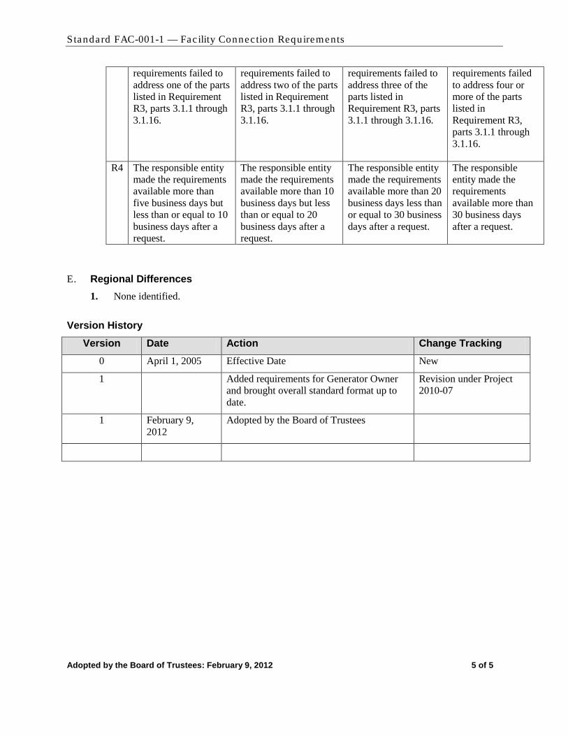
Standard FAC-001-1 — Facility Connection Requirements
Adopted by the Board of Trustees: February 9, 2012 5 of 5
requirements failed to address one of the parts listed in Requirement R3, parts 3.1.1 through 3.1.16.
requirements failed to address two of the parts listed in Requirement R3, parts 3.1.1 through 3.1.16.
requirements failed to address three of the parts listed in Requirement R3, parts 3.1.1 through 3.1.16.
requirements failed to address four or more of the parts listed in Requirement R3, parts 3.1.1 through 3.1.16.
R4 The responsible entity made the requirements available more than five business days but less than or equal to 10 business days after a request.
The responsible entity made the requirements available more than 10 business days but less than or equal to 20 business days after a request.
The responsible entity made the requirements available more than 20 business days less than or equal to 30 business days after a request.
The responsible entity made the requirements available more than 30 business days after a request.
E. Regional Differences 1. None identified.
Version History
Version Date Action Change Tracking 0 April 1, 2005 Effective Date New
1 Added requirements for Generator Owner and brought overall standard format up to date.
Revision under Project 2010-07
1 February 9, 2012
Adopted by the Board of Trustees

Standard FAC-002-1 — Coordination of Plans for New Facilities
1 of 3
A. Introduction 1. Title: Coordination of Plans For New Generation, Transmission, and End-User
Facilities
2. Number: FAC-002-1
3. Purpose: To avoid adverse impacts on reliability, Generator Owners and Transmission Owners and electricity end-users must meet facility connection and performance requirements.
4. Applicability:
4.1. Generator Owner
4.2. Transmission Owner
4.3. Distribution Provider
4.4. Load-Serving Entity
4.5. Transmission Planner
4.6. Planning Authority
5. (Proposed) Effective Date: The first day of the first calendar quarter six months after applicable regulatory approval; or in those jurisdictions where no regulatory approval is required, the first day of the first calendar quarter six months after Board of Trustees’ adoption.
B. Requirements R1. The Generator Owner, Transmission Owner, Distribution Provider, and Load-Serving Entity
seeking to integrate generation facilities, transmission facilities, and electricity end-user facilities shall each coordinate and cooperate on its assessments with its Transmission Planner and Planning Authority. The assessment shall include:
1.1. Evaluation of the reliability impact of the new facilities and their connections on the interconnected transmission systems.
1.2. Ensurance of compliance with NERC Reliability Standards and applicable Regional, subregional, Power Pool, and individual system planning criteria and facility connection requirements.
1.3. Evidence that the parties involved in the assessment have coordinated and cooperated on the assessment of the reliability impacts of new facilities on the interconnected transmission systems. While these studies may be performed independently, the results shall be jointly evaluated and coordinated by the entities involved.
1.4. Evidence that the assessment included steady-state, short-circuit, and dynamics studies as necessary to evaluate system performance under both normal and contingency conditions in accordance with Reliability Standards TPL-001-0, TPL-002-0, and TPL-003-0.
1.5. Documentation that the assessment included study assumptions, system performance, alternatives considered, and jointly coordinated recommendations.
R2. The Planning Authority, Transmission Planner, Generator Owner, Transmission Owner, Load-Serving Entity, and Distribution Provider shall each retain its documentation (of its evaluation of the reliability impact of the new facilities and their connections on the interconnected transmission systems) for three years and shall provide the documentation to the Regional

Standard FAC-002-1 — Coordination of Plans for New Facilities
2 of 3
Reliability Organization(s) and NERC on request (within 30 calendar days). (Retirement approved by NERC BOT pending applicable regulatory approval.)
C. Measures M1. The Planning Authority, Transmission Planner, Generator Owner, Transmission Owner, Load-
Serving Entity, and Distribution Provider’s documentation of its assessment of the reliability impacts of new facilities shall address all items in Reliability Standard FAC-002-0_R1.
M2. The Planning Authority, Transmission Planner, Generator Owner, Transmission Owner, Load-Serving Entity, and Distribution Provider shall each have evidence of its assessment of the reliability impacts of new facilities and their connections on the interconnected transmission systems is retained and provided to other entities in accordance with Reliability Standard FAC-002-0_R2. (Retirement approved by NERC BOT pending applicable regulatory approval.)
D. Compliance 1. Compliance Monitoring Process
1.1. Compliance Enforcement Authority Regional Entity.
1.2. Compliance Monitoring Period and Reset Timeframe Not applicable.
1.3. Compliance Monitoring and Enforcement Processes: Compliance Audits Self-Certifications Spot Checking Compliance Violation Investigations Self-Reporting
Complaints
1.4. Data Retention Evidence of the assessment of the reliability impacts of new facilities and their connections on the interconnected transmission systems: Three years.
1.5. Additional Compliance Information None
2. Violation Severity Levels (no changes)
E. Regional Differences 1. None identified.
Version History
Version Date Action Change Tracking 0 April 1, 2005 Effective Date New
0 January 13, 2006 Removed duplication of “Regional Reliability Organizations(s).
Errata
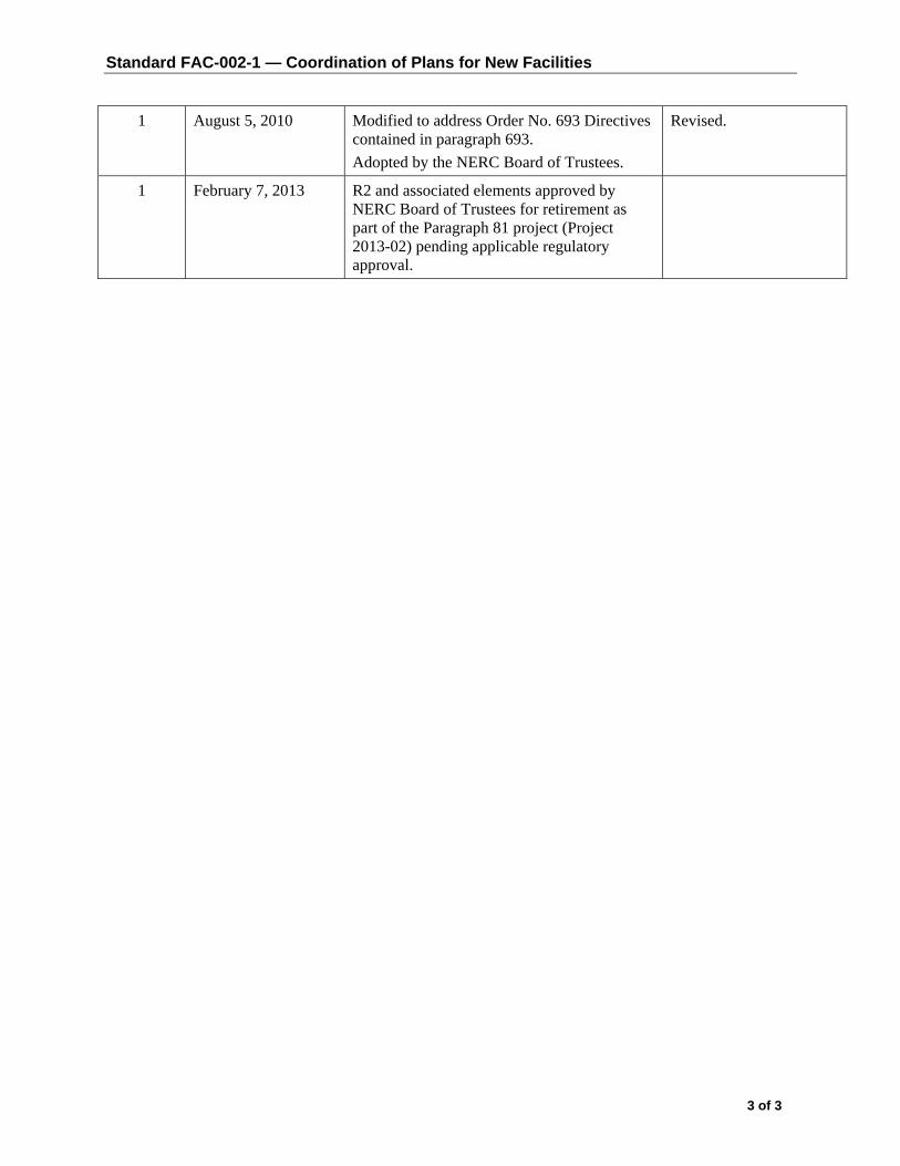
Standard FAC-002-1 — Coordination of Plans for New Facilities
3 of 3
1 August 5, 2010 Modified to address Order No. 693 Directives contained in paragraph 693. Adopted by the NERC Board of Trustees.
Revised.
1 February 7, 2013 R2 and associated elements approved by NERC Board of Trustees for retirement as part of the Paragraph 81 project (Project 2013-02) pending applicable regulatory approval.

FAC-003-3 — Transmission Vegetation Management
Page 3 of 32
A. Introduction 1. Title: Transmission Vegetation Management
2. Number: FAC-003-3
3. Purpose: To maintain a reliable electric transmission system by using a defense-in-
depth strategy to manage vegetation located on transmission rights of way (ROW) and minimize encroachments from vegetation located adjacent to the ROW, thus preventing the risk of those vegetation-related outages that could lead to Cascading.
4. Applicability
4.1. Functional Entities: 4.1.1. Applicable Transmission Owners
4.1.1.1 Transmission Owners that own Transmission Facilities defined in 4.2.
4.1.2 Applicable Generator Owners
4.1.2.1 Generator Owners that own generation Facilities defined in 4.3
4.2. Transmission Facilities: Defined below (referred to as “applicable lines”), including but not limited to those that cross lands owned by federal1
4.2. 1 Each overhead transmission line operated at 200kV or higher.
, state, provincial, public, private, or tribal entities:
4.2.2 Each overhead transmission line operated below 200kV identified as an element of an IROL under NERC Standard FAC-014 by the Planning Coordinator.
4.2.3 Each overhead transmission line operated below 200 kV identified as an element of a Major WECC Transfer Path in the Bulk Electric System by WECC.
4.2.4 Each overhead transmission line identified above (4.2.1 through 4.2.3) located outside the fenced area of the switchyard, station or substation and any portion of the span of the transmission line that is crossing the substation fence.
4.3. Generation Facilities: Defined below (referred to as “applicable lines”), including but not limited to those that cross lands owned by federal2
4.3.1 Overhead transmission lines that (1) extend greater than one mile or 1.609 kilometers beyond the fenced area of the generating station switchyard to the point of interconnection with a Transmission Owner’s Facility or (2) do not have a clear line
, state, provincial, public, private, or tribal entities:
1 EPAct 2005 section 1211c: “Access approvals by Federal agencies.” 2 Id.

FAC-003-3 — Transmission Vegetation Management
Page 4 of 32
of sight3
4.3.1.1 Operated at 200kV or higher; or
from the generating station switchyard fence to the point of interconnection with a Transmission Owner’s Facility and are:
4.3.1.2 Operated below 200kV identified as an element of an IROL under NERC Standard FAC-014 by the Planning Coordinator; or
4.3.1.3 Operated below 200 kV identified as an element of a Major WECC Transfer Path in the Bulk Electric System by WECC.
Enforcement: The Requirements within a Reliability Standard govern and will be enforced. The Requirements within a Reliability Standard define what an entity must do to be compliant and binds an entity to certain obligations of performance under Section 215 of the Federal Power Act. Compliance will in all cases be measured by determining whether a party met or failed to meet the Reliability Standard Requirement given the specific facts and circumstances of its use, ownership or operation of the bulk power system. Measures provide guidance on assessing non-compliance with the Requirements. Measures are the evidence that could be presented to demonstrate compliance with a Reliability Standard Requirement and are not intended to contain the quantitative metrics for determining satisfactory performance nor to limit how an entity may demonstrate compliance if valid alternatives to demonstrating compliance are available in a specific case. A Reliability Standard may be enforced in the absence of specified Measures. Entities must comply with the “Compliance” section in its entirety, including the Administrative Procedure that sets forth, among other things, reporting requirements. The “Guideline and Technical Basis” section, the Background section and text boxes with “Examples” and “Rationale” are provided for informational purposes. They are designed to convey guidance from NERC’s various activities. The “Guideline and Technical Basis” section and text boxes with “Examples” and “Rationale” are not intended to establish new Requirements under NERC’s Reliability Standards or to modify the Requirements in any existing NERC Reliability Standard. Implementation of the “Guideline and Technical Basis” section, the Background section and text boxes with “Examples” and “Rationale” is not a substitute for compliance with Requirements in NERC’s Reliability Standards.”
5. Background:
This standard uses three types of requirements to provide layers of protection to prevent vegetation related outages that could lead to Cascading:
3 “Clear line of sight” means the distance that can be seen by the average person without special instrumentation (e.g., binoculars, telescope, spyglasses, etc.) on a clear day.

FAC-003-3 — Transmission Vegetation Management
Page 5 of 32
a) Performance-based defines a particular reliability objective or outcome to be achieved. In its simplest form, a results-based requirement has four components: who, under what conditions (if any), shall perform what action, to achieve what particular bulk power system performance result or outcome?
b) Risk-based preventive requirements to reduce the risks of failure to acceptable tolerance levels. A risk-based reliability requirement should be framed as: who, under what conditions (if any), shall perform what action, to achieve what particular result or outcome that reduces a stated risk to the reliability of the bulk power system?
c) Competency-based defines a minimum set of capabilities an entity needs to have to demonstrate it is able to perform its designated reliability functions. A competency-based reliability requirement should be framed as: who, under what conditions (if any), shall have what capability, to achieve what particular result or outcome to perform an action to achieve a result or outcome or to reduce a risk to the reliability of the bulk power system?
The defense-in-depth strategy for reliability standards development recognizes that each requirement in a NERC reliability standard has a role in preventing system failures, and that these roles are complementary and reinforcing. Reliability standards should not be viewed as a body of unrelated requirements, but rather should be viewed as part of a portfolio of requirements designed to achieve an overall defense-in-depth strategy and comport with the quality objectives of a reliability standard.
This standard uses a defense-in-depth approach to improve the reliability of the electric Transmission system by:
• Requiring that vegetation be managed to prevent vegetation encroachment inside the flash-over clearance (R1 and R2);
• Requiring documentation of the maintenance strategies, procedures, processes and specifications used to manage vegetation to prevent potential flash-over conditions including consideration of 1) conductor dynamics and 2) the interrelationships between vegetation growth rates, control methods and the inspection frequency (R3);
• Requiring timely notification to the appropriate control center of vegetation conditions that could cause a flash-over at any moment (R4);
• Requiring corrective actions to ensure that flash-over distances will not be violated due to work constrains such as legal injunctions (R5);
• Requiring inspections of vegetation conditions to be performed annually (R6); and
• Requiring that the annual work needed to prevent flash-over is completed (R7).
For this standard, the requirements have been developed as follows:
Performance-based: Requirements 1 and 2
Competency-based: Requirement 3
FAC-003-3 — Transmission Vegetation Management
Page 6 of 32
Risk-based: Requirements 4, 5, 6 and 7
R3 serves as the first line of defense by ensuring that entities understand the problem they are trying to manage and have fully developed strategies and plans to manage the problem. R1, R2, and R7 serve as the second line of defense by requiring that entities carry out their plans and manage vegetation. R6, which requires inspections, may be either a part of the first line of defense (as input into the strategies and plans) or as a third line of defense (as a check of the first and second lines of defense). R4 serves as the final line of defense, as it addresses cases in which all the other lines of defense have failed.
Major outages and operational problems have resulted from interference between overgrown vegetation and transmission lines located on many types of lands and ownership situations. Adherence to the standard requirements for applicable lines on any kind of land or easement, whether they are Federal Lands, state or provincial lands, public or private lands, franchises, easements or lands owned in fee, will reduce and manage this risk. For the purpose of the standard the term “public lands” includes municipal lands, village lands, city lands, and a host of other governmental entities.
This standard addresses vegetation management along applicable overhead lines and does not apply to underground lines, submarine lines or to line sections inside an electric station boundary.
This standard focuses on transmission lines to prevent those vegetation related outages that could lead to Cascading. It is not intended to prevent customer outages due to tree contact with lower voltage distribution system lines. For example, localized customer service might be disrupted if vegetation were to make contact with a 69kV transmission line supplying power to a 12kV distribution station. However, this standard is not written to address such isolated situations which have little impact on the overall electric transmission system.
Since vegetation growth is constant and always present, unmanaged vegetation poses an increased outage risk, especially when numerous transmission lines are operating at or near their Rating. This can present a significant risk of consecutive line failures when lines are experiencing large sags thereby leading to Cascading. Once the first line fails the shift of the current to the other lines and/or the increasing system loads will lead to the second and subsequent line failures as contact to the vegetation under those lines occurs. Conversely, most other outage causes (such as trees falling into lines, lightning, animals, motor vehicles, etc.) are not an interrelated function of the shift of currents or the increasing system loading. These events are not any more likely to occur during heavy system loads than any other time. There is no cause-effect relationship which creates the probability of simultaneous occurrence of other such events. Therefore these types of events are highly unlikely to cause large-scale grid failures. Thus, this standard places the highest priority on the management of vegetation to prevent vegetation grow-ins.

FAC-003-3 — Transmission Vegetation Management
Page 7 of 32
B. Requirements and Measures
R1. Each applicable Transmission Owner and applicable Generator Owner shall manage vegetation to prevent encroachments into the MVCD of its applicable line(s) which are either an element of an IROL, or an element of a Major WECC Transfer Path; operating within their Rating and all Rated Electrical Operating Conditions of the types shown below4
1. An encroachment into the MVCD as shown in FAC-003-Table 2, observed in Real-time, absent a Sustained Outage,
[Violation Risk Factor: High] [Time Horizon: Real-time]:
5
2. An encroachment due to a fall-in from inside the ROW that caused a vegetation-related Sustained Outage,
6
3. An encroachment due to the blowing together of applicable lines and vegetation located inside the ROW that caused a vegetation-related Sustained Outage
7
4. An encroachment due to vegetation growth into the MVCD that caused a vegetation-related Sustained Outage.
,
8
M1. Each applicable Transmission Owner and applicable Generator Owner has evidence that it managed vegetation to prevent encroachment into the MVCD as described in R1. Examples of acceptable forms of evidence may include dated attestations, dated reports containing no Sustained Outages associated with encroachment types 2 through 4 above, or records confirming no Real-time observations of any MVCD encroachments. (R1)
R2. Each applicable Transmission Owner and applicable Generator Owner shall manage
vegetation to prevent encroachments into the MVCD of its applicable line(s) which are not either an element of an IROL, or an element of a Major WECC Transfer Path; operating within its Rating and all Rated Electrical Operating Conditions of the types shown below9
1. An encroachment into the MVCD, observed in Real-time, absent a Sustained Outage,
[Violation Risk Factor: Medium] [Time Horizon: Real-time]:
10
4 This requirement does not apply to circumstances that are beyond the control of an applicable Transmission Owner or applicable Generator Owner subject to this reliability standard, including natural disasters such as earthquakes, fires, tornados, hurricanes, landslides, wind shear, fresh gale, major storms as defined either by the applicable Transmission Owner or applicable Generator Owner or an applicable regulatory body, ice storms, and floods; human or animal activity such as logging, animal severing tree, vehicle contact with tree, or installation, removal, or digging of vegetation. Nothing in this footnote should be construed to limit the Transmission Owner’s or applicable Generator Owner’s right to exercise its full legal rights on the ROW.
5 If a later confirmation of a Fault by the applicable Transmission Owner or applicable Generator Owner shows that a vegetation encroachment within the MVCD has occurred from vegetation within the ROW, this shall be considered the equivalent of a Real-time observation. 6 Multiple Sustained Outages on an individual line, if caused by the same vegetation, will be reported as one outage regardless of the actual number of outages within a 24-hour period. 7 Id. 8 Id. 9 See footnote 4. 10 See footnote 5.
FAC-003-3 — Transmission Vegetation Management
Page 8 of 32
2. An encroachment due to a fall-in from inside the ROW that caused a vegetation-related Sustained Outage,11
3. An encroachment due to blowing together of applicable lines and vegetation located inside the ROW that caused a vegetation-related Sustained Outage,
12
4. An encroachment due to vegetation growth into the line MVCD that caused a vegetation-related Sustained Outage
13
M2. Each applicable Transmission Owner and applicable Generator Owner has evidence that it managed vegetation to prevent encroachment into the MVCD as described in R2. Examples of acceptable forms of evidence may include dated attestations, dated reports containing no Sustained Outages associated with encroachment types 2 through 4 above, or records confirming no Real-time observations of any MVCD encroachments. (R2)
R3. Each applicable Transmission Owner and applicable Generator
Owner shall have documented maintenance strategies or procedures or processes or specifications it uses to prevent the encroachment of vegetation into the MVCD of its applicable lines that accounts for the following: 3.1 Movement of applicable line conductors under their Rating and
all Rated Electrical Operating Conditions; 3.2 Inter-relationships between vegetation growth rates, vegetation
control methods, and inspection frequency. [Violation Risk Factor: Lower] [Time Horizon: Long Term Planning]
M3. The maintenance strategies or procedures or processes or specifications provided
demonstrate that the applicable Transmission Owner and applicable Generator Owner can prevent encroachment into the MVCD considering the factors identified in the requirement. (R3)
R4. Each applicable Transmission Owner and applicable Generator Owner, without any
intentional time delay, shall notify the control center holding switching authority for the associated applicable line when the applicable Transmission Owner and applicable Generator Owner has confirmed the existence of a vegetation condition that is likely to cause a Fault at any moment [Violation Risk Factor: Medium] [Time Horizon: Real-time].
M4. Each applicable Transmission Owner and applicable Generator Owner that has a
confirmed vegetation condition likely to cause a Fault at any moment will have evidence that it notified the control center holding switching authority for the associated transmission line without any intentional time delay. Examples of evidence
11 See footnote 6. 12 Id. 13 Id.
FAC-003-3 — Transmission Vegetation Management
Page 9 of 32
may include control center logs, voice recordings, switching orders, clearance orders and subsequent work orders. (R4)
R5. When a applicable Transmission Owner and applicable Generator Owner is constrained
from performing vegetation work on an applicable line operating within its Rating and all Rated Electrical Operating Conditions, and the constraint may lead to a vegetation encroachment into the MVCD prior to the implementation of the next annual work plan, then the applicable Transmission Owner or applicable Generator Owner shall take corrective action to ensure continued vegetation management to prevent encroachments [Violation Risk Factor: Medium] [Time Horizon: Operations Planning].
M5. Each applicable Transmission Owner and applicable Generator Owner has evidence of
the corrective action taken for each constraint where an applicable transmission line was put at potential risk. Examples of acceptable forms of evidence may include initially-planned work orders, documentation of constraints from landowners, court orders, inspection records of increased monitoring, documentation of the de-rating of lines, revised work orders, invoices, or evidence that the line was de-energized. (R5)
R6. Each applicable Transmission Owner and applicable Generator Owner shall perform a
Vegetation Inspection of 100% of its applicable transmission lines (measured in units of choice - circuit, pole line, line miles or kilometers, etc.) at least once per calendar year and with no more than 18 calendar months between inspections on the same ROW14
[Violation Risk Factor: Medium] [Time Horizon: Operations Planning].
M6. Each applicable Transmission Owner and applicable Generator Owner has evidence that it conducted Vegetation Inspections of the transmission line ROW for all applicable lines at least once per calendar year but with no more than 18 calendar months between inspections on the same ROW. Examples of acceptable forms of evidence may include completed and dated work orders, dated invoices, or dated inspection records. (R6)
R7. Each applicable Transmission Owner and applicable Generator Owner shall complete
100% of its annual vegetation work plan of applicable lines to ensure no vegetation encroachments occur within the MVCD. Modifications to the work plan in response to changing conditions or to findings from vegetation inspections may be made (provided they do not allow encroachment of vegetation into the MVCD) and must be documented. The percent completed calculation is based on the number of units actually completed divided by the number of units in the final amended plan (measured in units of choice - circuit, pole line, line miles or kilometers, etc.) Examples of reasons for modification to annual plan may include [Violation Risk Factor: Medium] [Time Horizon: Operations Planning]:
14 When the applicable Transmission Owner or applicable Generator Owner is prevented from performing a Vegetation Inspection within the timeframe in R6 due to a natural disaster, the TO or GO is granted a time extension that is equivalent to the duration of the time the TO or GO was prevented from performing the Vegetation Inspection.

FAC-003-3 — Transmission Vegetation Management
Page 10 of 32
• Change in expected growth rate/ environmental factors • Circumstances that are beyond the control of an applicable Transmission Owner or
applicable Generator Owner15
• Rescheduling work between growing seasons
• Crew or contractor availability/ Mutual assistance agreements • Identified unanticipated high priority work • Weather conditions/Accessibility • Permitting delays • Land ownership changes/Change in land use by the landowner • Emerging technologies
M7. Each applicable Transmission Owner and applicable Generator Owner has evidence
that it completed its annual vegetation work plan for its applicable lines. Examples of acceptable forms of evidence may include a copy of the completed annual work plan (as finally modified), dated work orders, dated invoices, or dated inspection records. (R7)
C. Compliance
1. Compliance Monitoring Process 1.1 Compliance Enforcement Authority
The Regional Entity shall serve as the Compliance Enforcement Authority unless the applicable entity is owned, operated, or controlled by the Regional Entity. In such cases the ERO or a Regional entity approved by FERC or other applicable governmental authority shall serve as the CEA.
For NERC, a third-party monitor without vested interest in the outcome for NERC shall serve as the Compliance Enforcement Authority.
1.2 Evidence Retention The following evidence retention periods identify the period of time an entity is required to retain specific evidence to demonstrate compliance. For instances where the evidence retention period specified below is shorter than the time since the last audit, the Compliance Enforcement Authority may ask an entity to provide other evidence to show that it was compliant for the full time period since the last audit.
The applicable Transmission Owner and applicable Generator Owner retains data or evidence to show compliance with Requirements R1, R2, R3, R5, R6 and R7, Measures M1, M2, M3, M5, M6 and M7 for three calendar years unless directed by its Compliance Enforcement Authority to retain specific evidence for a longer period of time as part of an investigation.
15 Circumstances that are beyond the control of an applicable Transmission Owner or applicable Generator Owner include but are not limited to natural disasters such as earthquakes, fires, tornados, hurricanes, landslides, ice storms, floods, or major storms as defined either by the TO or GO or an applicable regulatory body.

FAC-003-3 — Transmission Vegetation Management
Page 11 of 32
The applicable Transmission Owner and applicable Generator Owner retains data or evidence to show compliance with Requirement R4, Measure M4 for most recent 12 months of operator logs or most recent 3 months of voice recordings or transcripts of voice recordings, unless directed by its Compliance Enforcement Authority to retain specific evidence for a longer period of time as part of an investigation.
If a applicable Transmission Owner or applicable Generator Owner is found non-compliant, it shall keep information related to the non-compliance until found compliant or for the time period specified above, whichever is longer.
The Compliance Enforcement Authority shall keep the last audit records and all requested and submitted subsequent audit records.
1.3 Compliance Monitoring and Enforcement Processes:
Compliance Audit
Self-Certification
Spot Checking
Compliance Violation Investigation
Self-Reporting
Complaint
Periodic Data Submittal
1.4 Additional Compliance Information
Periodic Data Submittal: The applicable Transmission Owner and applicable Generator Owner will submit a quarterly report to its Regional Entity, or the Regional Entity’s designee, identifying all Sustained Outages of applicable lines operated within their Rating and all Rated Electrical Operating Conditions as determined by the applicable Transmission Owner or applicable Generator Owner to have been caused by vegetation, except as excluded in footnote 2, and including as a minimum the following:
o The name of the circuit(s), the date, time and duration of the outage; the voltage of the circuit; a description of the cause of the outage; the category associated with the Sustained Outage; other pertinent comments; and any countermeasures taken by the applicable Transmission Owner or applicable Generator Owner.
A Sustained Outage is to be categorized as one of the following:
o Category 1A — Grow-ins: Sustained Outages caused by vegetation growing into applicable lines, that are identified as an element of an
FAC-003-3 — Transmission Vegetation Management
Page 12 of 32
IROL or Major WECC Transfer Path, by vegetation inside and/or outside of the ROW;
o Category 1B — Grow-ins: Sustained Outages caused by vegetation growing into applicable lines, but are not identified as an element of an IROL or Major WECC Transfer Path, by vegetation inside and/or outside of the ROW;
o Category 2A — Fall-ins: Sustained Outages caused by vegetation falling into applicable lines that are identified as an element of an IROL or Major WECC Transfer Path, from within the ROW;
o Category 2B — Fall-ins: Sustained Outages caused by vegetation falling into applicable lines, but are not identified as an element of an IROL or Major WECC Transfer Path, from within the ROW;
o Category 3 — Fall-ins: Sustained Outages caused by vegetation falling into applicable lines from outside the ROW;
o Category 4A — Blowing together: Sustained Outages caused by vegetation and applicable lines that are identified as an element of an IROL or Major WECC Transfer Path, blowing together from within the ROW.
o Category 4B — Blowing together: Sustained Outages caused by vegetation and applicable lines, but are not identified as an element of an IROL or Major WECC Transfer Path, blowing together from within the ROW.
The Regional Entity will report the outage information provided by applicable Transmission Owners and applicable Generator Owners, as per the above, quarterly to NERC, as well as any actions taken by the Regional Entity as a result of any of the reported Sustained Outages.

FAC-003-3 — Transmission Vegetation Management
Page 13 of 32
Table of Compliance Elements
R# Time Horizon
VRF Violation Severity Level
Lower Moderate High Severe
R1 Real-time High
The responsible entity failed to manage vegetation to prevent encroachment into the MVCD of a line identified as an element of an IROL or Major WECC transfer path and encroachment into the MVCD as identified in FAC-003-Table 2 was observed in real time absent a Sustained Outage.
The responsible entity failed to manage vegetation to prevent encroachment into the MVCD of a line identified as an element of an IROL or Major WECC transfer path and a vegetation-related Sustained Outage was caused by one of the following: • A fall-in from inside the
active transmission line ROW
• Blowing together of applicable lines and vegetation located inside the active transmission line ROW
• A grow-in
R2 Real-time Medium
The responsible entity failed to manage vegetation to prevent encroachment into the MVCD of a line not identified as an element of an IROL or Major WECC transfer path and encroachment into the MVCD as identified in FAC-003-Table 2 was observed in real time absent a Sustained Outage.
The responsible entity failed to manage vegetation to prevent encroachment into the MVCD of a line not identified as an element of an IROL or Major WECC transfer path and a vegetation-related Sustained Outage was caused by one of the following: • A fall-in from inside the
active transmission line

FAC-003-3 — Transmission Vegetation Management
Page 14 of 32
ROW • Blowing together of
applicable lines and vegetation located inside the active transmission line ROW
• A grow-in
R3 Long-Term Planning Lower
The responsible entity has maintenance strategies or documented procedures or processes or specifications but has not accounted for the inter-relationships between vegetation growth rates, vegetation control methods, and inspection frequency, for the responsible entity’s applicable lines. (Requirement R3, Part 3.2)
The responsible entity has maintenance strategies or documented procedures or processes or specifications but has not accounted for the movement of transmission line conductors under their Rating and all Rated Electrical Operating Conditions, for the responsible entity’s applicable lines. Requirement R3, Part 3.1)
The responsible entity does not have any maintenance strategies or documented procedures or processes or specifications used to prevent the encroachment of vegetation into the MVCD, for the responsible entity’s applicable lines.
R4 Real-time Medium
The responsible entity experienced a confirmed vegetation threat and notified the control center holding switching authority for that applicable line, but there was intentional delay in that notification.
The responsible entity experienced a confirmed vegetation threat and did not notify the control center holding switching authority for that applicable line.
R5 Operations Planning Medium
The responsible entity did not take corrective action when it was constrained from performing planned vegetation work where an applicable line was put at potential risk.
R6 Operations Medium The responsible entity The responsible entity failed The responsible entity failed to The responsible entity failed to

FAC-003-3 — Transmission Vegetation Management
Page 15 of 32
Planning failed to inspect 5% or less of its applicable lines (measured in units of choice - circuit, pole line, line miles or kilometers, etc.)
to inspect more than 5% up to and including 10% of its applicable lines (measured in units of choice - circuit, pole line, line miles or kilometers, etc.).
inspect more than 10% up to and including 15% of its applicable lines (measured in units of choice - circuit, pole line, line miles or kilometers, etc.).
inspect more than 15% of its applicable lines (measured in units of choice - circuit, pole line, line miles or kilometers, etc.).
R7 Operations Planning Medium
The responsible entity failed to complete 5% or less of its annual vegetation work plan for its applicable lines (as finally modified).
The responsible entity failed to complete more than 5% and up to and including 10% of its annual vegetation work plan for its applicable lines (as finally modified).
The responsible entity failed to complete more than 10% and up to and including 15% of its annual vegetation work plan for its applicable lines (as finally modified).
The responsible entity failed to complete more than 15% of its annual vegetation work plan for its applicable lines (as finally modified).
D. Regiona l Diffe rences
None. E. In te rpre ta tions
None. F. As s oc ia ted Documents
Guideline and Technical Basis (attached).

FAC-003-3 — Transmission Vegetation Management
Page 16 of 32
GGuuiiddeelliinnee aanndd TTeecchhnniiccaall BBaassiiss Effective dates: The first two sentences of the Effective Dates section is standard language used in most NERC standards to cover the general effective date and is sufficient to cover the vast majority of situations. Five special cases are needed to cover effective dates for individual lines which undergo transitions after the general effective date. These special cases cover the effective dates for those lines which are initially becoming subject to the standard, those lines which are changing their applicability within the standard, and those lines which are changing in a manner that removes their applicability to the standard. Case 1 is needed because the Planning Coordinators may designate lines below 200 kV to become elements of an IROL or Major WECC Transfer Path in a future Planning Year (PY). For example, studies by the Planning Coordinator in 2011 may identify a line to have that designation beginning in PY 2021, ten years after the planning study is performed. It is not intended for the Standard to be immediately applicable to, or in effect for, that line until that future PY begins. The effective date provision for such lines ensures that the line will become subject to the standard on January 1 of the PY specified with an allowance of at least 12 months for the applicable Transmission Owner or applicable Generator Owner to make the necessary preparations to achieve compliance on that line. The table below has some explanatory examples of the application.
Date that Planning Study is
completed
PY the line will become
an IROL element Date 1 Date 2
Effective Date The latter of Date 1
or Date 2 05/15/2011 2012 05/15/2012 01/01/2012 05/15/2012 05/15/2011 2013 05/15/2012 01/01/2013 01/01/2013 05/15/2011 2014 05/15/2012 01/01/2014 01/01/2014 05/15/2011 2021 05/15/2012 01/01/2021 01/01/2021
Case 2 is needed because a line operating below 200kV designated as an element of an IROL or Major WECC Transfer Path may be removed from that designation due to system improvements, changes in generation, changes in loads or changes in studies and analysis of the network. Case 3 is needed because a line operating at 200 kV or above that once was designated as an element of an IROL or Major WECC Transfer Path may be removed from that designation due to system improvements, changes in generation, changes in loads or changes in studies and analysis of the network. Such changes result in the need to apply R1 to that line until that date is reached and then to apply R2 to that line thereafter. Case 4 is needed because an existing line that is to be operated at 200 kV or above can be acquired by an applicable Transmission Owner or applicable Generator Owner from a third party

FAC-003-3 — Transmission Vegetation Management
Page 17 of 32
such as a Distribution Provider or other end-user who was using the line solely for local distribution purposes, but the applicable Transmission Owner or applicable Generator Owner, upon acquisition, is incorporating the line into the interconnected electrical energy transmission network which will thereafter make the line subject to the standard. Case 5 is needed because an existing line that is operated below 200 kV can be acquired by an applicable Transmission Owner or applicable Generator Owner from a third party such as a Distribution Provider or other end-user who was using the line solely for local distribution purposes, but the applicable Transmission Owner or applicable Generator Owner, upon acquisition, is incorporating the line into the interconnected electrical energy transmission network. In this special case the line upon acquisition was designated as an element of an Interconnection Reliability Operating Limit (IROL) or an element of a Major WECC Transfer Path. Defined Terms: Explanation for revising the definition of ROW: The current NERC glossary definition of Right of Way has been modified to include Generator Owners and to address the matter set forth in Paragraph 734 of FERC Order 693. The Order pointed out that Transmission Owners may in some cases own more property or rights than are needed to reliably operate transmission lines. This modified definition represents a slight but significant departure from the strict legal definition of “right of way” in that this definition is based on engineering and construction considerations that establish the width of a corridor from a technical basis. The pre-2007 maintenance records are included in the revised definition to allow the use of such vegetation widths if there were no engineering or construction standards that referenced the width of right of way to be maintained for vegetation on a particular line but the evidence exists in maintenance records for a width that was in fact maintained prior to this standard becoming mandatory. Such widths may be the only information available for lines that had limited or no vegetation easement rights and were typically maintained primarily to ensure public safety. This standard does not require additional easement rights to be purchased to satisfy a minimum right of way width that did not exist prior to this standard becoming mandatory. The Project 2010-07 team further modified that proposed definition to include applicable Generator Owners. Explanation for revising the definition of Vegetation Inspections: The current glossary definition of this NERC term is being modified to include Generator Owners and to allow both maintenance inspections and vegetation inspections to be performed concurrently. This allows potential efficiencies, especially for those lines with minimal vegetation and/or slow vegetation growth rates. The Project 2010-07 team further modified that proposed definition to include applicable Generator Owners.
FAC-003-3 — Transmission Vegetation Management
Page 18 of 32
Explanation of the definition of the MVCD: The MVCD is a calculated minimum distance that is derived from the Gallet Equations. This is a method of calculating a flash over distance that has been used in the design of high voltage transmission lines. Keeping vegetation away from high voltage conductors by this distance will prevent voltage flash-over to the vegetation. See the explanatory text below for Requirement R3 and associated Figure 1. Table 2 below provides MVCD values for various voltages and altitudes. Details of the equations and an example calculation are provided in Appendix 1 of the Technical Reference Document. Requirements R1 and R2: R1 and R2 are performance-based requirements. The reliability objective or outcome to be achieved is the management of vegetation such that there are no vegetation encroachments within a minimum distance of transmission lines. Content-wise, R1 and R2 are the same requirements; however, they apply to different Facilities. Both R1 and R2 require each applicable Transmission Owner or applicable Generator Owner to manage vegetation to prevent encroachment within the MVCD of transmission lines. R1 is applicable to lines that are identified as an element of an IROL or Major WECC Transfer Path. R2 is applicable to all other lines that are not elements of IROLs, and not elements of Major WECC Transfer Paths.
The separation of applicability (between R1 and R2) recognizes that inadequate vegetation management for an applicable line that is an element of an IROL or a Major WECC Transfer Path is a greater risk to the interconnected electric transmission system than applicable lines that are not elements of IROLs or Major WECC Transfer Paths. Applicable lines that are not elements of IROLs or Major WECC Transfer Paths do require effective vegetation management, but these lines are comparatively less operationally significant. As a reflection of this difference in risk impact, the Violation Risk Factors (VRFs) are assigned as High for R1 and Medium for R2.
Requirements R1 and R2 state that if inadequate vegetation management allows vegetation to encroach within the MVCD distance as shown in Table 2, it is a violation of the standard. Table 2 distances are the minimum clearances that will prevent spark-over based on the Gallet equations as described more fully in the Technical Reference document.
These requirements assume that transmission lines and their conductors are operating within their Rating. If a line conductor is intentionally or inadvertently operated beyond its Rating and Rated Electrical Operating Condition (potentially in violation of other standards), the occurrence of a clearance encroachment may occur solely due to that condition. For example, emergency actions taken by an applicable Transmission Owner or applicable Generator Owner or Reliability Coordinator to protect an Interconnection may cause excessive sagging and an outage. Another example would be ice loading beyond the line’s Rating and Rated Electrical Operating Condition. Such vegetation-related encroachments and outages are not violations of this standard.
Evidence of failures to adequately manage vegetation include real-time observation of a vegetation encroachment into the MVCD (absent a Sustained Outage), or a vegetation-related encroachment resulting in a Sustained Outage due to a fall-in from inside the ROW, or a

FAC-003-3 — Transmission Vegetation Management
Page 19 of 32
vegetation-related encroachment resulting in a Sustained Outage due to the blowing together of the lines and vegetation located inside the ROW, or a vegetation-related encroachment resulting in a Sustained Outage due to a grow-in. Faults which do not cause a Sustained outage and which are confirmed to have been caused by vegetation encroachment within the MVCD are considered the equivalent of a Real-time observation for violation severity levels.
With this approach, the VSLs for R1 and R2 are structured such that they directly correlate to the severity of a failure of an applicable Transmission Owner or applicable Generator Owner to manage vegetation and to the corresponding performance level of the Transmission Owner’s vegetation program’s ability to meet the objective of “preventing the risk of those vegetation related outages that could lead to Cascading.” Thus violation severity increases with an applicable Transmission Owner’s or applicable Generator Owner’s inability to meet this goal and its potential of leading to a Cascading event. The additional benefits of such a combination are that it simplifies the standard and clearly defines performance for compliance. A performance-based requirement of this nature will promote high quality, cost effective vegetation management programs that will deliver the overall end result of improved reliability to the system.
Multiple Sustained Outages on an individual line can be caused by the same vegetation. For example initial investigations and corrective actions may not identify and remove the actual outage cause then another outage occurs after the line is re-energized and previous high conductor temperatures return. Such events are considered to be a single vegetation-related Sustained Outage under the standard where the Sustained Outages occur within a 24 hour period.
The MVCD is a calculated minimum distance stated in feet (or meters) to prevent spark-over, for various altitudes and operating voltages that is used in the design of Transmission Facilities. Keeping vegetation from entering this space will prevent transmission outages.
If the applicable Transmission Owner or applicable Generator Owner has applicable lines operated at nominal voltage levels not listed in Table 2, then the applicable TO or applicable GO should use the next largest clearance distance based on the next highest nominal voltage in the table to determine an acceptable distance. Requirement R3: R3 is a competency based requirement concerned with the maintenance strategies, procedures, processes, or specifications, an applicable Transmission Owner or applicable Generator Owner uses for vegetation management. An adequate transmission vegetation management program formally establishes the approach the applicable Transmission Owner or applicable Generator Owner uses to plan and perform vegetation work to prevent transmission Sustained Outages and minimize risk to the transmission system. The approach provides the basis for evaluating the intent, allocation of appropriate resources, and the competency of the applicable Transmission Owner or applicable Generator Owner in managing vegetation. There are many acceptable approaches to manage vegetation and avoid Sustained Outages. However, the applicable Transmission Owner or applicable Generator Owner must be able to show the documentation of its approach and how it conducts work to maintain clearances.
An example of one approach commonly used by industry is ANSI Standard A300, part 7. However, regardless of the approach a utility uses to manage vegetation, any approach an

FAC-003-3 — Transmission Vegetation Management
Page 20 of 32
applicable Transmission Owner or applicable Generator Owner chooses to use will generally contain the following elements:
1. the maintenance strategy used (such as minimum vegetation-to-conductor distance or maximum vegetation height) to ensure that MVCD clearances are never violated.
2. the work methods that the applicable Transmission Owner or applicable Generator Owner uses to control vegetation
3. a stated Vegetation Inspection frequency 4. an annual work plan
The conductor’s position in space at any point in time is continuously changing in reaction to a number of different loading variables. Changes in vertical and horizontal conductor positioning are the result of thermal and physical loads applied to the line. Thermal loading is a function of line current and the combination of numerous variables influencing ambient heat dissipation including wind velocity/direction, ambient air temperature and precipitation. Physical loading applied to the conductor affects sag and sway by combining physical factors such as ice and wind loading. The movement of the transmission line conductor and the MVCD is illustrated in Figure 1 below. In the Technical Reference document more figures and explanations of conductor dynamics are provided.
Figure 1
A cross-section view of a single conductor at a given point along the span is shown with six possible conductor positions due to movement resulting from thermal and mechanical loading.
Requirement R4: R4 is a risk-based requirement. It focuses on preventative actions to be taken by the applicable Transmission Owner or applicable Generator Owner for the mitigation of Fault risk when a vegetation threat is confirmed. R4 involves the notification of potentially threatening vegetation conditions, without any intentional delay, to the control center holding switching authority for that specific transmission line. Examples of acceptable unintentional delays may include

FAC-003-3 — Transmission Vegetation Management
Page 21 of 32
communication system problems (for example, cellular service or two-way radio disabled), crews located in remote field locations with no communication access, delays due to severe weather, etc. Confirmation is key that a threat actually exists due to vegetation. This confirmation could be in the form of an applicable Transmission Owner or applicable Generator Owner employee who personally identifies such a threat in the field. Confirmation could also be made by sending out an employee to evaluate a situation reported by a landowner. Vegetation-related conditions that warrant a response include vegetation that is near or encroaching into the MVCD (a grow-in issue) or vegetation that could fall into the transmission conductor (a fall-in issue). A knowledgeable verification of the risk would include an assessment of the possible sag or movement of the conductor while operating between no-load conditions and its rating. The applicable Transmission Owner or applicable Generator Owner has the responsibility to ensure the proper communication between field personnel and the control center to allow the control center to take the appropriate action until or as the vegetation threat is relieved. Appropriate actions may include a temporary reduction in the line loading, switching the line out of service, or other preparatory actions in recognition of the increased risk of outage on that circuit. The notification of the threat should be communicated in terms of minutes or hours as opposed to a longer time frame for corrective action plans (see R5). All potential grow-in or fall-in vegetation-related conditions will not necessarily cause a Fault at any moment. For example, some applicable Transmission Owners or applicable Generator Owners may have a danger tree identification program that identifies trees for removal with the potential to fall near the line. These trees would not require notification to the control center unless they pose an immediate fall-in threat. Requirement R5: R5 is a risk-based requirement. It focuses upon preventative actions to be taken by the applicable Transmission Owner or applicable Generator Owner for the mitigation of Sustained Outage risk when temporarily constrained from performing vegetation maintenance. The intent of this requirement is to deal with situations that prevent the applicable Transmission Owner or applicable Generator Owner from performing planned vegetation management work and, as a result, have the potential to put the transmission line at risk. Constraints to performing vegetation maintenance work as planned could result from legal injunctions filed by property owners, the discovery of easement stipulations which limit the applicable Transmission Owner’s or applicable Generator Owner’s rights, or other circumstances. This requirement is not intended to address situations where the transmission line is not at potential risk and the work event can be rescheduled or re-planned using an alternate work methodology. For example, a land owner may prevent the planned use of chemicals on non-threatening, low growth vegetation but agree to the use of mechanical clearing. In this case the applicable Transmission Owner or applicable Generator Owner is not under any immediate time

FAC-003-3 — Transmission Vegetation Management
Page 22 of 32
constraint for achieving the management objective, can easily reschedule work using an alternate approach, and therefore does not need to take interim corrective action. However, in situations where transmission line reliability is potentially at risk due to a constraint, the applicable Transmission Owner or applicable Generator Owner is required to take an interim corrective action to mitigate the potential risk to the transmission line. A wide range of actions can be taken to address various situations. General considerations include:
• Identifying locations where the applicable Transmission Owner or applicable Generator Owner is constrained from performing planned vegetation maintenance work which potentially leaves the transmission line at risk.
• Developing the specific action to mitigate any potential risk associated with not performing the vegetation maintenance work as planned.
• Documenting and tracking the specific action taken for the location. • In developing the specific action to mitigate the potential risk to the transmission line
the applicable Transmission Owner or applicable Generator Owner could consider location specific measures such as modifying the inspection and/or maintenance intervals. Where a legal constraint would not allow any vegetation work, the interim corrective action could include limiting the loading on the transmission line.
• The applicable Transmission Owner or applicable Generator Owner should document and track the specific corrective action taken at each location. This location may be indicated as one span, one tree or a combination of spans on one property where the constraint is considered to be temporary.
Requirement R6: R6 is a risk-based requirement. This requirement sets a minimum time period for completing Vegetation Inspections. The provision that Vegetation Inspections can be performed in conjunction with general line inspections facilitates a Transmission Owner’s ability to meet this requirement. However, the applicable Transmission Owner or applicable Generator Owner may determine that more frequent vegetation specific inspections are needed to maintain reliability levels, based on factors such as anticipated growth rates of the local vegetation, length of the local growing season, limited ROW width, and local rainfall. Therefore it is expected that some transmission lines may be designated with a higher frequency of inspections. The VSLs for Requirement R6 have levels ranked by the failure to inspect a percentage of the applicable lines to be inspected. To calculate the appropriate VSL the applicable Transmission Owner or applicable Generator Owner may choose units such as: circuit, pole line, line miles or kilometers, etc. For example, when an applicable Transmission Owner or applicable Generator Owner operates 2,000 miles of applicable transmission lines this applicable Transmission Owner or applicable Generator Owner will be responsible for inspecting all the 2,000 miles of lines at least once during the calendar year. If one of the included lines was 100 miles long, and if it was not inspected during the year, then the amount failed to inspect would be 100/2000 = 0.05 or 5%. The “Low VSL” for R6 would apply in this example.
FAC-003-3 — Transmission Vegetation Management
Page 23 of 32
Requirement R7: R7 is a risk-based requirement. The applicable Transmission Owner or applicable Generator Owner is required to complete its an annual work plan for vegetation management to accomplish the purpose of this standard. Modifications to the work plan in response to changing conditions or to findings from vegetation inspections may be made and documented provided they do not put the transmission system at risk. The annual work plan requirement is not intended to necessarily require a “span-by-span”, or even a “line-by-line” detailed description of all work to be performed. It is only intended to require that the applicable Transmission Owner or applicable Generator Owner provide evidence of annual planning and execution of a vegetation management maintenance approach which successfully prevents encroachment of vegetation into the MVCD. For example, when an applicable Transmission Owner or applicable Generator Owner identifies 1,000 miles of applicable transmission lines to be completed in the applicable Transmission Owner’s or applicable Generator Owner’s annual plan, the applicable Transmission Owner or applicable Generator Owner will be responsible completing those identified miles. If a applicable Transmission Owner or applicable Generator Owner makes a modification to the annual plan that does not put the transmission system at risk of an encroachment the annual plan may be modified. If 100 miles of the annual plan is deferred until next year the calculation to determine what percentage was completed for the current year would be: 1000 – 100 (deferred miles) = 900 modified annual plan, or 900 / 900 = 100% completed annual miles. If an applicable Transmission Owner or applicable Generator Owner only completed 875 of the total 1000 miles with no acceptable documentation for modification of the annual plan the calculation for failure to complete the annual plan would be: 1000 – 875 = 125 miles failed to complete then, 125 miles (not completed) / 1000 total annual plan miles = 12.5% failed to complete. The ability to modify the work plan allows the applicable Transmission Owner or applicable Generator Owner to change priorities or treatment methodologies during the year as conditions or situations dictate. For example recent line inspections may identify unanticipated high priority work, weather conditions (drought) could make herbicide application ineffective during the plan year, or a major storm could require redirecting local resources away from planned maintenance. This situation may also include complying with mutual assistance agreements by moving resources off the applicable Transmission Owner’s or applicable Generator Owner’s system to work on another system. Any of these examples could result in acceptable deferrals or additions to the annual work plan provided that they do not put the transmission system at risk of a vegetation encroachment. In general, the vegetation management maintenance approach should use the full extent of the applicable Transmission Owner’s or applicable Generator Owner’s easement, fee simple and other legal rights allowed. A comprehensive approach that exercises the full extent of legal rights on the ROW is superior to incremental management because in the long term it reduces the overall potential for encroachments, and it ensures that future planned work and future planned inspection cycles are sufficient.

FAC-003-3 — Transmission Vegetation Management
Page 24 of 32
When developing the annual work plan the applicable Transmission Owner or applicable Generator Owner should allow time for procedural requirements to obtain permits to work on federal, state, provincial, public, tribal lands. In some cases the lead time for obtaining permits may necessitate preparing work plans more than a year prior to work start dates. Applicable Transmission Owners or applicable Generator Owners may also need to consider those special landowner requirements as documented in easement instruments. This requirement sets the expectation that the work identified in the annual work plan will be completed as planned. Therefore, deferrals or relevant changes to the annual plan shall be documented. Depending on the planning and documentation format used by the applicable Transmission Owner or applicable Generator Owner, evidence of successful annual work plan execution could consist of signed-off work orders, signed contracts, printouts from work management systems, spreadsheets of planned versus completed work, timesheets, work inspection reports, or paid invoices. Other evidence may include photographs, and walk-through reports.

FAC-003-3 — Transmission Vegetation Management
Page 25 of 32
FFAACC--000033 —— TTAABBLLEE 22 —— MMiinniimmuumm VVeeggeettaattiioonn CClleeaarraannccee DDiissttaanncceess ((MMVVCCDD))1
For Alternating Current Voltages (feet) 166
( AC ) Nominal System Voltage
(KV)
( AC ) Maximum
System Voltage (kV)17
MVCD (feet)
MVCD (feet)
MVCD feet
MVCD feet
MVCD feet
MVCD feet
MVCD feet
MVCD feet
MVCD feet
MVCD feet
MVCD feet
MVCD feet
Over sea level up to 500 ft
Over 500 ft up to 1000 ft
Over 1000 ft up to 2000 ft
Over 2000 ft up to
3000 ft
Over 3000 ft up to
4000 ft
Over 4000 ft up to
5000 ft
Over 5000 ft up to
6000 ft
Over 6000 ft up to
7000 ft
Over 7000 ft up to
8000 ft
Over 8000 ft up to
9000 ft
Over 9000 ft up to
10000 ft
Over 10000 ft
up to 11000 ft
765 800 8.2ft 8.33ft 8.61ft 8.89ft 9.17ft 9.45ft 9.73ft 10.01ft 10.29ft 10.57ft 10.85ft 11.13ft
500 550 5.15ft 5.25ft 5.45ft 5.66ft 5.86ft 6.07ft 6.28ft 6.49ft 6.7ft 6.92ft 7.13ft 7.35ft
345 362 3.19ft 3.26ft 3.39ft 3.53ft 3.67ft 3.82ft 3.97ft 4.12ft 4.27ft 4.43ft 4.58ft 4.74ft
287 302 3.88ft 3.96ft 4.12ft 4.29ft 4.45ft 4.62ft 4.79ft 4.97ft 5.14ft 5.32ft 5.50ft 5.68ft
230 242 3.03ft 3.09ft 3.22ft 3.36ft 3.49ft 3.63ft 3.78ft 3.92ft 4.07ft 4.22ft 4.37ft 4.53ft
161* 169 2.05ft 2.09ft 2.19ft 2.28ft 2.38ft 2.48ft 2.58ft 2.69ft 2.8ft 2.91ft 3.03ft 3.14ft
138* 145 1.74ft 1.78ft 1.86ft 1.94ft 2.03ft 2.12ft 2.21ft 2.3ft 2.4ft 2.49ft 2.59ft 2.7ft
115* 121 1.44ft 1.47ft 1.54ft 1.61ft 1.68ft 1.75ft 1.83ft 1.91ft 1.99ft 2.07ft 2.16ft 2.25ft
88* 100 1.18ft 1.21ft 1.26ft 1.32ft 1.38ft 1.44ft 1.5ft 1.57ft 1.64ft 1.71ft 1.78ft 1.86ft
69* 72 0.84ft 0.86ft 0.90ft 0.94ft 0.99ft 1.03ft 1.08ft 1.13ft 1.18ft 1.23ft 1.28ft 1.34ft
∗ Such lines are applicable to this standard only if PC has determined such per FAC-014 (refer to the Applicability Section above)
16 The distances in this Table are the minimums required to prevent Flash-over; however prudent vegetation maintenance practices dictate that substantially greater distances will be achieved at time of vegetation maintenance. 17 Where applicable lines are operated at nominal voltages other than those listed, the applicable Transmission Owner or applicable Generator Owner should use the maximum system voltage to determine the appropriate clearance for that line.

FAC-003-3 — Transmission Vegetation Management
Page 26 of 32
TTAABBLLEE 22 ((CCOONNTT)) —— MMiinniimmuumm VVeeggeettaattiioonn CClleeaarraannccee DDiissttaanncceess ((MMVVCCDD))77
For Alternating Current Voltages (meters)
( AC ) Nominal System Voltage
(KV)
( AC ) Maximum
System Voltage (kV)
8
MVCD meters
MVCD meters
MVCD meters
MVCD meters
MVCD meters
MVCD meters
MVCD meters
MVCD meters
MVCD meters
MVCD meters
MVCD meters
MVCD meters
Over sea level up to 152.4 m
Over 152.4 m up to 304.8 m
Over 304.8 m up to 609.6m
Over 609.6m up to 914.4m
Over 914.4m up
to 1219.2m
Over 1219.2m
up to 1524m
Over 1524 m up to 1828.8
m
Over 1828.8m
up to 2133.6m
Over 2133.6m
up to 2438.4m
Over 2438.4m up to 2743.2m
Over 2743.2m up
to 3048m
Over 3048m up
to 3352.8m
765 800 2.49m 2.54m 2.62m 2.71m 2.80m 2.88m 2.97m 3.05m 3.14m 3.22m 3.31m 3.39m
500 550 1.57m 1.6m 1.66m 1.73m 1.79m 1.85m 1.91m 1.98m 2.04m 2.11m 2.17m 2.24m
345 362 0.97m 0.99m 1.03m 1.08m 1.12m 1.16m 1.21m 1.26m 1.30m 1.35m 1.40m 1.44m
287 302 1.18m 0.88m 1.26m 1.31m 1.36m 1.41m 1.46m 1.51m 1.57m 1.62m 1.68m 1.73m
230 242 0.92m 0.94m 0.98m 1.02m 1.06m 1.11m 1.15m 1.19m 1.24m 1.29m 1.33m 1.38m
161* 169 0.62m 0.64m 0.67m 0.69m 0.73m 0.76m 0.79m 0.82m 0.85m 0.89m 0.92m 0.96m
138* 145 0.53m 0.54m 0.57m 0.59m 0.62m 0.65m 0.67m 0.70m 0.73m 0.76m 0.79m 0.82m
115* 121 0.44m 0.45m 0.47m 0.49m 0.51m 0.53m 0.56m 0.58m 0.61m 0.63m 0.66m 0.69m
88* 100 0.36m 0.37m 0.38m 0.40m 0.42m 0.44m 0.46m 0.48m 0.50m 0.52m 0.54m 0.57m
69* 72 0.26m 0.26m 0.27m 0.29m 0.30m 0.31m 0.33m 0.34m 0.36m 0.37m 0.39m 0.41m
∗ Such lines are applicable to this standard only if PC has determined such per FAC-014 (refer to the Applicability Section above)

FAC-003-3 — Transmission Vegetation Management
Page 27 of 32
TTAABBLLEE 22 ((CCOONNTT)) —— MMiinniimmuumm VVeeggeettaattiioonn CClleeaarraannccee DDiissttaanncceess ((MMVVCCDD))77
For Direct Current Voltages feet (meters)
( DC ) Nominal Pole to Ground Voltage
(kV)
MVCD meters
MVCD meters
MVCD meters
MVCD meters
MVCD meters
MVCD meters
MVCD meters
MVCD meters
MVCD meters
MVCD meters
MVCD meters
MVCD meters
Over sea level up to
500 ft
Over 500 ft up to 1000 ft
Over 1000 ft up to 2000 ft
Over 2000 ft up to 3000 ft
Over 3000 ft up to 4000 ft
Over 4000 ft up to 5000 ft
Over 5000 ft up to 6000 ft
Over 6000 ft up to 7000 ft
Over 7000 ft up to 8000 ft
Over 8000 ft up to 9000 ft
Over 9000 ft up to 10000 ft
Over 10000 ft up to 11000 ft
(Over sea level up to 152.4 m)
(Over 152.4 m
up to 304.8 m
(Over 304.8 m
up to 609.6m)
(Over 609.6m up to 914.4m
(Over 914.4m up
to 1219.2m
(Over 1219.2m
up to 1524m
(Over 1524 m up to 1828.8
m)
(Over 1828.8m
up to 2133.6m)
(Over 2133.6m
up to 2438.4m)
(Over 2438.4m
up to 2743.2m)
(Over 2743.2m
up to 3048m)
(Over 3048m up
to 3352.8m)
±750 14.12ft (4.30m)
14.31ft (4.36m)
14.70ft (4.48m)
15.07ft (4.59m)
15.45ft (4.71m)
15.82ft (4.82m)
16.2ft (4.94m)
16.55ft (5.04m)
16.91ft (5.15m)
17.27ft (5.26m)
17.62ft (5.37m)
17.97ft (5.48m)
±600 10.23ft (3.12m)
10.39ft (3.17m)
10.74ft (3.26m)
11.04ft (3.36m)
11.35ft (3.46m)
11.66ft (3.55m)
11.98ft (3.65m)
12.3ft (3.75m)
12.62ft (3.85m)
12.92ft (3.94m)
13.24ft (4.04m)
13.54ft (4.13m)
±500 8.03ft
(2.45m) 8.16ft
(2.49m) 8.44ft
(2.57m) 8.71ft
(2.65m) 8.99ft
(2.74m) 9.25ft
(2.82m) 9.55ft
(2.91m) 9.82ft
(2.99m) 10.1ft
(3.08m) 10.38ft (3.16m)
10.65ft (3.25m)
10.92ft (3.33m)
±400 6.07ft
(1.85m) 6.18ft
(1.88m) 6.41ft
(1.95m) 6.63ft
(2.02m) 6.86ft
(2.09m) 7.09ft
(2.16m) 7.33ft
(2.23m) 7.56ft
(2.30m) 7.80ft
(2.38m) 8.03ft
(2.45m) 8.27ft
(2.52m) 8.51ft
(2.59m)
±250 3.50ft
(1.07m) 3.57ft
(1.09m) 3.72ft
(1.13m) 3.87ft
(1.18m) 4.02ft
(1.23m) 4.18ft
(1.27m) 4.34ft
(1.32m) 4.5ft
(1.37m) 4.66ft
(1.42m) 4.83ft
(1.47m) 5.00ft
(1.52m) 5.17ft
(1.58m)

FAC-003-3 — Transmission Vegetation Management
Page 28 of 32
Notes: The SDT determined that the use of IEEE 516-2003 in version 1 of FAC-003 was a misapplication. The SDT consulted specialists who advised that the Gallet Equation would be a technically justified method. The explanation of why the Gallet approach is more appropriate is explained in the paragraphs below. The drafting team sought a method of establishing minimum clearance distances that uses realistic weather conditions and realistic maximum transient over-voltages factors for in-service transmission lines. The SDT considered several factors when looking at changes to the minimum vegetation to conductor distances in FAC-003-1:
• avoid the problem associated with referring to tables in another standard (IEEE-516-2003)
• transmission lines operate in non-laboratory environments (wet conditions) • transient over-voltage factors are lower for in-service transmission lines than for
inadvertently re-energized transmission lines with trapped charges. FAC-003-1 uses the minimum air insulation distance (MAID) without tools formula provided in IEEE 516-2003 to determine the minimum distance between a transmission line conductor and vegetation. The equations and methods provided in IEEE 516 were developed by an IEEE Task Force in 1968 from test data provided by thirteen independent laboratories. The distances provided in IEEE 516 Tables 5 and 7 are based on the withstand voltage of a dry rod-rod air gap, or in other words, dry laboratory conditions. Consequently, the validity of using these distances in an outside environment application has been questioned. FAC-003-01 allowed Transmission Owners to use either Table 5 or Table 7 to establish the minimum clearance distances. Table 7 could be used if the Transmission Owner knew the maximum transient over-voltage factor for its system. Otherwise, Table 5 would have to be used. Table 5 represented minimum air insulation distances under the worst possible case for transient over-voltage factors. These worst case transient over-voltage factors were as follows: 3.5 for voltages up to 362 kV phase to phase; 3.0 for 500 - 550 kV phase to phase; and 2.5 for 765 to 800 kV phase to phase. These worst case over-voltage factors were also a cause for concern in this particular application of the distances. In general, the worst case transient over-voltages occur on a transmission line that is inadvertently re-energized immediately after the line is de-energized and a trapped charge is still present. The intent of FAC-003 is to keep a transmission line that is in service from becoming de-energized (i.e. tripped out) due to spark-over from the line conductor to nearby vegetation. Thus, the worst case transient overvoltage assumptions are not appropriate for this application. Rather, the appropriate over voltage values are those that occur only while the line is energized. Typical values of transient over-voltages of in-service lines, as such, are not readily available in the literature because they are negligible compared with the maximums. A conservative value for the maximum transient over-voltage that can occur anywhere along the length of an in-

FAC-003-3 — Transmission Vegetation Management
Page 29 of 32
service ac line is approximately 2.0 per unit. This value is a conservative estimate of the transient over-voltage that is created at the point of application (e.g. a substation) by switching a capacitor bank without pre-insertion devices (e.g. closing resistors). At voltage levels where capacitor banks are not very common (e.g. Maximum System Voltage of 362 kV), the maximum transient over-voltage of an in-service ac line are created by fault initiation on adjacent ac lines and shunt reactor bank switching. These transient voltages are usually 1.5 per unit or less. Even though these transient over-voltages will not be experienced at locations remote from the bus at which they are created, in order to be conservative, it is assumed that all nearby ac lines are subjected to this same level of over-voltage. Thus, a maximum transient over-voltage factor of 2.0 per unit for transmission lines operated at 302 kV and below is considered to be a realistic maximum in this application. Likewise, for ac transmission lines operated at Maximum System Voltages of 362 kV and above a transient over-voltage factor of 1.4 per unit is considered a realistic maximum. The Gallet Equations are an accepted method for insulation coordination in tower design. These equations are used for computing the required strike distances for proper transmission line insulation coordination. They were developed for both wet and dry applications and can be used with any value of transient over-voltage factor. The Gallet Equation also can take into account various air gap geometries. This approach was used to design the first 500 kV and 765 kV lines in North America. If one compares the MAID using the IEEE 516-2003 Table 7 (table D.5 for English values) with the critical spark-over distances computed using the Gallet wet equations, for each of the nominal voltage classes and identical transient over-voltage factors, the Gallet equations yield a more conservative (larger) minimum distance value. Distances calculated from either the IEEE 516 (dry) formulas or the Gallet “wet” formulas are not vastly different when the same transient overvoltage factors are used; the “wet” equations will consistently produce slightly larger distances than the IEEE 516 equations when the same transient overvoltage is used. While the IEEE 516 equations were only developed for dry conditions the Gallet equations have provisions to calculate spark-over distances for both wet and dry conditions. While EPRI is currently trying to establish empirical data for spark-over distances to live vegetation, there are no spark-over formulas currently derived expressly for vegetation to conductor minimum distances. Therefore the SDT chose a proven method that has been used in other EHV applications. The Gallet equations relevance to wet conditions and the selection of a Transient Overvoltage Factor that is consistent with the absence of trapped charges on an in-service transmission line make this methodology a better choice. The following table is an example of the comparison of distances derived from IEEE 516 and the Gallet equations.

FAC-003-3 — Transmission Vegetation Management
Page 30 of 32
Comparison of spark-over distances computed using Gallet wet equations vs. IEEE 516-2003 MAID distances
Table 7
(Table D.5 for feet)
( AC ) ( AC ) Transient Clearance (ft.) IEEE 516-2003 Nom System Max System Over-voltage Gallet (wet) MAID (ft) Voltage (kV) Voltage (kV) Factor (T) @ Alt. 3000 feet @ Alt. 3000 feet
765 800 2.0 14.36 13.95
500 550 2.4 11.0 10.07
345 362 3.0 8.55 7.47
230 242 3.0 5.28 4.2
115 121 3.0 2.46 2.1 Rationale: During development of this standard, text boxes were embedded within the standard to explain the rationale for various parts of the standard. Upon BOT approval, the text from the rationale text boxes was moved to this section. Rationale for Applicability (section 4.2.4): The areas excluded in 4.2.4 were excluded based on comments from industry for reasons summarized as follows: 1) There is a very low risk from vegetation in this area. Based on an informal survey, no TOs reported such an event. 2) Substations, switchyards, and stations have many inspection and maintenance activities that are necessary for reliability. Those existing process manage the threat. As such, the formal steps in this standard are not well suited for this environment. 3) Specifically addressing the areas where the standard does and does not apply makes the standard clearer. Rationale for Applicability (section 4.3): Within the text of NERC Reliability Standard FAC-003-3, “transmission line(s) and “applicable line(s) can also refer to the generation Facilities as referenced in 4.3 and its subsections. Rationale for R1 and R2: Lines with the highest significance to reliability are covered in R1; all other lines are covered in R2. Rationale for the types of failure to manage vegetation which are listed in order of increasing degrees of severity in non-compliant performance as it relates to a failure of an applicable Transmission Owner's or applicable Generator Owner’s vegetation maintenance program:
FAC-003-3 — Transmission Vegetation Management
Page 31 of 32
1. This management failure is found by routine inspection or Fault event investigation, and is normally symptomatic of unusual conditions in an otherwise sound program. 2. This management failure occurs when the height and location of a side tree within the ROW is not adequately addressed by the program. 3. This management failure occurs when side growth is not adequately addressed and may be indicative of an unsound program. 4. This management failure is usually indicative of a program that is not addressing the most fundamental dynamic of vegetation management, (i.e. a grow-in under the line). If this type of failure is pervasive on multiple lines, it provides a mechanism for a Cascade. Rationale for R3: The documentation provides a basis for evaluating the competency of the applicable Transmission Owner’s or applicable Generator Owner’s vegetation program. There may be many acceptable approaches to maintain clearances. Any approach must demonstrate that the applicable Transmission Owner or applicable Generator Owner avoids vegetation-to-wire conflicts under all Ratings and all Rated Electrical Operating Conditions. See Figure Rationale for R4: This is to ensure expeditious communication between the applicable Transmission Owner or applicable Generator Owner and the control center when a critical situation is confirmed. Rationale for R5: Legal actions and other events may occur which result in constraints that prevent the applicable Transmission Owner or applicable Generator Owner from performing planned vegetation maintenance work. In cases where the transmission line is put at potential risk due to constraints, the intent is for the applicable Transmission Owner and applicable Generator Owner to put interim measures in place, rather than do nothing. The corrective action process is not intended to address situations where a planned work methodology cannot be performed but an alternate work methodology can be used. Rationale for R6: Inspections are used by applicable Transmission Owners and applicable Generator Owners to assess the condition of the entire ROW. The information from the assessment can be used to determine risk, determine future work and evaluate recently-completed work. This requirement sets a minimum Vegetation Inspection frequency of once per calendar year but with no more than 18 months between inspections on the same ROW. Based upon average growth rates across North America and on common utility practice, this minimum frequency is reasonable. Transmission Owners should consider local and environmental factors that could warrant more frequent inspections.
FAC-003-3 — Transmission Vegetation Management
Page 32 of 32
Rationale for R7: This requirement sets the expectation that the work identified in the annual work plan will be completed as planned. It allows modifications to the planned work for changing conditions, taking into consideration anticipated growth of vegetation and all other environmental factors, provided that those modifications do not put the transmission system at risk of a vegetation encroachment. Version History Version Date Action Change Tracking
3 September 29, 2011
Using the latest draft of FAC-003-2 from the Project 2007-07 SDT, modified proposed definitions and Applicability to include Generator Owners of a certain length.
Revision under Project 2010-07
3 May 9, 2012 Adopted by Board of Trustees

Standard FAC-008-3 — Facility Ratings
Page 1 of 11
A. Introduction
1. Title: Facility Ratings
2. Number: FAC-008-3
3. Purpose: To ensure that Facility Ratings used in the reliable planning and operation of the Bulk Electric System (BES) are determined based on technically sound principles. A Facility Rating is essential for the determination of System Operating Limits.
4. Applicability
4.1. Transmission Owner.
4.2. Generator Owner.
5. Effective Date: The first day of the first calendar quarter that is twelve months beyond the date approved by applicable regulatory authorities, or in those jurisdictions where regulatory approval is not required, the first day of the first calendar quarter twelve months following BOT adoption.
B. Requirements R1. Each Generator Owner shall have documentation for determining the Facility Ratings of its
solely and jointly owned generator Facility(ies) up to the low side terminals of the main step up transformer if the Generator Owner does not own the main step up transformer and the high side terminals of the main step up transformer if the Generator Owner owns the main step up transformer. [Violation Risk Factor: Lower] [Time Horizon: Long-term Planning]
1.1. The documentation shall contain assumptions used to rate the generator and at least one of the following:
Design or construction information such as design criteria, ratings provided by equipment manufacturers, equipment drawings and/or specifications, engineering analyses, method(s) consistent with industry standards (e.g. ANSI and IEEE), or an established engineering practice that has been verified by testing or engineering analysis.
Operational information such as commissioning test results, performance testing or historical performance records, any of which may be supplemented by engineering analyses.
1.2. The documentation shall be consistent with the principle that the Facility Ratings do not exceed the most limiting applicable Equipment Rating of the individual equipment that comprises that Facility.
R2. Each Generator Owner shall have a documented methodology for determining Facility Ratings (Facility Ratings methodology) of its solely and jointly owned equipment connected between the location specified in R1 and the point of interconnection with the Transmission Owner that contains all of the following. [Violation Risk Factor: Medium] [Time Horizon: Long-term Planning]
2.1. The methodology used to establish the Ratings of the equipment that comprises the Facility(ies) shall be consistent with at least one of the following:
Ratings provided by equipment manufacturers or obtained from equipment manufacturer specifications such as nameplate rating.

Standard FAC-008-3 — Facility Ratings
Page 2 of 11
One or more industry standards developed through an open process such as Institute of Electrical and Electronic Engineers (IEEE) or International Council on Large Electric Systems (CIGRE).
A practice that has been verified by testing, performance history or engineering analysis.
2.2. The underlying assumptions, design criteria, and methods used to determine the Equipment Ratings identified in Requirement R2, Part 2.1 including identification of how each of the following were considered:
2.2.1. Equipment Rating standard(s) used in development of this methodology.
2.2.2. Ratings provided by equipment manufacturers or obtained from equipment manufacturer specifications.
2.2.3. Ambient conditions (for particular or average conditions or as they vary in real-time).
2.2.4. Operating limitations.1
2.3. A statement that a Facility Rating shall respect the most limiting applicable Equipment Rating of the individual equipment that comprises that Facility.
2.4. The process by which the Rating of equipment that comprises a Facility is determined.
2.4.1. The scope of equipment addressed shall include, but not be limited to, conductors, transformers, relay protective devices, terminal equipment, and series and shunt compensation devices.
2.4.2. The scope of Ratings addressed shall include, as a minimum, both Normal and Emergency Ratings.
R3. Each Transmission Owner shall have a documented methodology for determining Facility Ratings (Facility Ratings methodology) of its solely and jointly owned Facilities (except for those generating unit Facilities addressed in R1 and R2) that contains all of the following: [Violation Risk Factor: Medium] [ Time Horizon: Long-term Planning]
3.1. The methodology used to establish the Ratings of the equipment that comprises the Facility shall be consistent with at least one of the following:
Ratings provided by equipment manufacturers or obtained from equipment manufacturer specifications such as nameplate rating.
One or more industry standards developed through an open process such as Institute of Electrical and Electronics Engineers (IEEE) or International Council on Large Electric Systems (CIGRE).
A practice that has been verified by testing, performance history or engineering analysis.
3.2. The underlying assumptions, design criteria, and methods used to determine the Equipment Ratings identified in Requirement R3, Part 3.1 including identification of how each of the following were considered:
3.2.1. Equipment Rating standard(s) used in development of this methodology.
1 Such as temporary de-ratings of impaired equipment in accordance with good utility practice.

Standard FAC-008-3 — Facility Ratings
Page 3 of 11
3.2.2. Ratings provided by equipment manufacturers or obtained from equipment manufacturer specifications.
3.2.3. Ambient conditions (for particular or average conditions or as they vary in real-time).
3.2.4. Operating limitations.2
3.3. A statement that a Facility Rating shall respect the most limiting applicable Equipment Rating of the individual equipment that comprises that Facility.
3.4. The process by which the Rating of equipment that comprises a Facility is determined.
3.4.1. The scope of equipment addressed shall include, but not be limited to, transmission conductors, transformers, relay protective devices, terminal equipment, and series and shunt compensation devices.
3.4.2. The scope of Ratings addressed shall include, as a minimum, both Normal and Emergency Ratings.
R4. Each Transmission Owner shall make its Facility Ratings methodology and each Generator Owner shall each make its documentation for determining its Facility Ratings and its Facility Ratings methodology available for inspection and technical review by those Reliability Coordinators, Transmission Operators, Transmission Planners and Planning Coordinators that have responsibility for the area in which the associated Facilities are located, within 21 calendar days of receipt of a request. [Violation Risk Factor: Lower] [Time Horizon: Operations Planning] (Retirement approved by NERC BOT pending applicable regulatory approval.)
R5. If a Reliability Coordinator, Transmission Operator, Transmission Planner or Planning Coordinator provides documented comments on its technical review of a Transmission Owner’s Facility Ratings methodology or Generator Owner’s documentation for determining its Facility Ratings and its Facility Rating methodology, the Transmission Owner or Generator Owner shall provide a response to that commenting entity within 45 calendar days of receipt of those comments. The response shall indicate whether a change will be made to the Facility Ratings methodology and, if no change will be made to that Facility Ratings methodology, the reason why. [Violation Risk Factor: Lower] [Time Horizon: Operations Planning] (Retirement approved by NERC BOT pending applicable regulatory approval.)
R6. Each Transmission Owner and Generator Owner shall have Facility Ratings for its solely and jointly owned Facilities that are consistent with the associated Facility Ratings methodology or documentation for determining its Facility Ratings. [Violation Risk Factor: Medium] [Time Horizon: Operations Planning]
R7. Each Generator Owner shall provide Facility Ratings (for its solely and jointly owned Facilities that are existing Facilities, new Facilities, modifications to existing Facilities and re-ratings of existing Facilities) to its associated Reliability Coordinator(s), Planning Coordinator(s), Transmission Planner(s), Transmission Owner(s) and Transmission Operator(s) as scheduled by such requesting entities. [Violation Risk Factor: Medium] [Time Horizon: Operations Planning]
R8. Each Transmission Owner (and each Generator Owner subject to Requirement R2) shall provide requested information as specified below (for its solely and jointly owned Facilities that are existing Facilities, new Facilities, modifications to existing Facilities and re-ratings of existing Facilities) to its associated Reliability Coordinator(s), Planning Coordinator(s),
2 Such as temporary de-ratings of impaired equipment in accordance with good utility practice.

Standard FAC-008-3 — Facility Ratings
Page 4 of 11
Transmission Planner(s), Transmission Owner(s) and Transmission Operator(s): [Violation Risk Factor: Medium] [Time Horizon: Operations Planning]
8.1. As scheduled by the requesting entities:
8.1.1. Facility Ratings
8.1.2. Identity of the most limiting equipment of the Facilities
8.2. Within 30 calendar days (or a later date if specified by the requester), for any requested Facility with a Thermal Rating that limits the use of Facilities under the requester’s authority by causing any of the following: 1) An Interconnection Reliability Operating Limit, 2) A limitation of Total Transfer Capability, 3) An impediment to generator deliverability, or 4) An impediment to service to a major load center:
8.2.1. Identity of the existing next most limiting equipment of the Facility
8.2.2. The Thermal Rating for the next most limiting equipment identified in Requirement R8, Part 8.2.1.
C. Measures M1. Each Generator Owner shall have documentation that shows how its Facility Ratings were
determined as identified in Requirement 1.
M2. Each Generator Owner shall have a documented Facility Ratings methodology that includes all of the items identified in Requirement 2, Parts 2.1 through 2.4.
M3. Each Transmission Owner shall have a documented Facility Ratings methodology that includes all of the items identified in Requirement 3, Parts 3.1 through 3.4.
Each Transmission Owner shall have evidence, such as a copy of a dated electronic note, or other comparable evidence to show that it made its Facility Ratings methodology available for inspection within 21 calendar days of a request in accordance with Requirement 4. The Generator Owner shall have evidence, such as a copy of a dated electronic note, or other comparable evidence to show that it made its documentation for determining its Facility Ratings or its Facility Ratings methodology available for inspection within 21 calendar days of a request in accordance with Requirement R4. (Retirement approved by NERC BOT pending applicable regulatory approval.)
If the Reliability Coordinator, Transmission Operator, Transmission Planner or Planning Coordinator provides documented comments on its technical review of a Transmission Owner’s or Generator Owner’s Facility Ratings methodology or a Generator Owner’s documentation for determining its Facility Ratings, the Transmission Owner or Generator Owner shall have evidence, (such as a copy of a dated electronic or hard copy note, or other comparable evidence from the Transmission Owner or Generator Owner addressed to the commenter that includes the response to the comment,) that it provided a response to that commenting entity in accordance with Requirement R5. (Retirement approved by NERC BOT pending applicable regulatory approval.)
M4. Each Transmission Owner and Generator Owner shall have evidence to show that its Facility Ratings are consistent with the documentation for determining its Facility Ratings as specified in Requirement R1 or consistent with its Facility Ratings methodology as specified in Requirements R2 and R3 (Requirement R6).
M5. Each Generator Owner shall have evidence, such as a copy of a dated electronic note, or other comparable evidence to show that it provided its Facility Ratings to its associated Reliability

Standard FAC-008-3 — Facility Ratings
Page 5 of 11
Coordinator(s), Planning Coordinator(s), Transmission Planner(s), Transmission Owner(s) and Transmission Operator(s) in accordance with Requirement R7.
M6. Each Transmission Owner (and Generator Owner subject to Requirement R2) shall have evidence, such as a copy of a dated electronic note, or other comparable evidence to show that it provided its Facility Ratings and identity of limiting equipment to its associated Reliability Coordinator(s), Planning Coordinator(s), Transmission Planner(s), Transmission Owner(s) and Transmission Operator(s) in accordance with Requirement R8.
D. Compliance
1. Compliance Monitoring Process
1.1. Compliance Enforcement Authority
Regional Entity
1.2. Compliance Monitoring and Enforcement Processes:
Self-Certifications
Spot Checking
Compliance Audits
Self-Reporting
Compliance Violation Investigations
Complaints
1.3. Data Retention
The Generator Owner shall keep its current documentation (for R1) and any modifications to the documentation that were in force since last compliance audit period for Measure M1 and Measure M6.
The Generator Owner shall keep its current, in force Facility Ratings methodology (for R2) and any modifications to the methodology that were in force since last compliance audit period for Measure M2 and Measure M6.
The Transmission Owner shall keep its current, in force Facility Ratings methodology (for R3) and any modifications to the methodology that were in force since the last compliance audit for Measure M3 and Measure M6.
The Transmission Owner and Generator Owner shall keep its current, in force Facility Ratings and any changes to those ratings for three calendar years for Measure M6.
The Generator Owner and Transmission Owner shall each keep evidence for Measure M4, and Measure M5, for three calendar years. (Retirement approved by NERC BOT pending applicable regulatory approval.)
The Generator Owner shall keep evidence for Measure M7 for three calendar years.
The Transmission Owner (and Generator Owner that is subject to Requirement R2) shall keep evidence for Measure M8 for three calendar years.
If a Generator Owner or Transmission Owner is found non-compliant, it shall keep information related to the non-compliance until found compliant.

Standard FAC-008-3 — Facility Ratings
Page 6 of 11
The Compliance Enforcement Authority shall keep the last audit and all subsequent compliance records.
1.4. Additional Compliance Information
None

Standard FAC-008-3 — Facility Ratings
Page 7 of 11
Violation Severity Levels
R # Lower VSL Moderate VSL High VSL Severe VSL
R1
N/A The Generator Owner’s Facility Rating documentation did not address Requirement R1, Part 1.1.
The Generator Owner’s Facility Rating documentation did not address Requirement R1, Part 1.2.
The Generator Owner failed to provide documentation for determining its Facility Ratings.
R2 The Generator Owner failed to include in its Facility Rating methodology one of the following Parts of Requirement R2:
2.1.
2.2.1
2.2.2
2.2.3
2.2.4
The Generator Owner failed to include in its Facility Rating methodology two of the following Parts of Requirement R2:
2.1
2.2.1
2.2.2
2.2.3
2.2.4
The Generator Owner’s Facility Rating methodology did not address all the components of Requirement R2, Part 2.4.
OR
The Generator Owner failed to include in its Facility Rating Methodology, three of the following Parts of Requirement R2:
2.1.
2.2.1
2.2.2
2.2.3
2.2.4
The Generator Owner’s Facility Rating methodology failed to recognize a facility's rating based on the most limiting component rating as required in Requirement R2, Part 2.3
OR
The Generator Owner failed to include in its Facility Rating Methodology four or more of the following Parts of Requirement R2:
2.1
2.2.1
2.2.2
2.2.3
2.2.4
R3 The Transmission Owner failed to include in its Facility Rating methodology one of the following Parts of Requirement R3:
3.1
3.2.1
The Transmission Owner failed to include in its Facility Rating methodology two of the following Parts of Requirement R3:
3.1
3.2.1
The Transmission Owner’s Facility Rating methodology did not address either of the following Parts of Requirement R3:
3.4.1
3.4.2
The Transmission Owner’s Facility Rating methodology failed to recognize a Facility's rating based on the most limiting component rating as required in Requirement R3, Part 3.3
OR

Standard FAC-008-3 — Facility Ratings
Page 8 of 11
R # Lower VSL Moderate VSL High VSL Severe VSL
3.2.2
3.2.3
3.2.4
3.2.2
3.2.3
3.2.4
OR
The Transmission Owner failed to include in its Facility Rating methodology three of the following Parts of Requirement R3:
3.1
3.2.1
3.2.2
3.2.3
3.2.4
The Transmission Owner failed to include in its Facility Rating methodology four or more of the following Parts of Requirement R3:
3.1
3.2.1
3.2.2
3.2.3
3.2.4
R4
(Retirement approved by NERC BOT pending applicable regulatory approval.)
The responsible entity made its Facility Ratings methodology or Facility Ratings documentation available within more than 21 calendar days but less than or equal to 31 calendar days after a request.
The responsible entity made its Facility Ratings methodology or Facility Ratings documentation available within more than 31 calendar days but less than or equal to 41 calendar days after a request.
The responsible entity made its Facility Rating methodology or Facility Ratings documentation available within more than 41 calendar days but less than or equal to 51 calendar days after a request.
The responsible entity failed to make its Facility Ratings methodology or Facility Ratings documentation available in more than 51 calendar days after a request. (R3)
R5
(Retirement approved by NERC BOT pending applicable regulatory approval.)
The responsible entity provided a response in more than 45 calendar days but less than or equal to 60 calendar days after a request. (R5)
The responsible entity provided a response in more than 60 calendar days but less than or equal to 70 calendar days after a request.
OR
The responsible entity provided a response within 45 calendar days, and the response indicated that a change will not be made to the Facility Ratings methodology or Facility Ratings documentation but did not indicate why no change will be made. (R5)
The responsible entity provided a response in more than 70 calendar days but less than or equal to 80 calendar days after a request.
OR
The responsible entity provided a response within 45 calendar days, but the response did not indicate whether a change will be made to the Facility Ratings methodology or Facility Ratings documentation. (R5)
The responsible entity failed to provide a response as required in more than 80 calendar days after the comments were received. (R5)

Standard FAC-008-3 — Facility Ratings
Page 9 of 11
R # Lower VSL Moderate VSL High VSL Severe VSL
R6 The responsible entity failed to establish Facility Ratings consistent with the associated Facility Ratings methodology or documentation for determining the Facility Ratings for 5% or less of its solely owned and jointly owned Facilities. (R6)
The responsible entity failed to establish Facility Ratings consistent with the associated Facility Ratings methodology or documentation for determining the Facility Ratings for more than 5% or more, but less than up to (and including) 10% of its solely owned and jointly owned Facilities. (R6)
The responsible entity failed to establish Facility Ratings consistent with the associated Facility Ratings methodology or documentation for determining the Facility Ratings for more than 10% up to (and including) 15% of its solely owned and jointly owned Facilities. (R6)
The responsible entity failed to establish Facility Ratings consistent with the associated Facility Ratings methodology or documentation for determining the Facility Ratings for more than15% of its solely owned and jointly owned Facilities. (R6)
R7 The Generator Owner provided its Facility Ratings to all of the requesting entities but missed meeting the schedules by up to and including 15 calendar days.
The Generator Owner provided its Facility Ratings to all of the requesting entities but missed meeting the schedules by more than 15 calendar days but less than or equal to 25 calendar days.
The Generator Owner provided its Facility Ratings to all of the requesting entities but missed meeting the schedules by more than 25 calendar days but less than or equal to 35 calendar days.
The Generator Owner provided its Facility Ratings to all of the requesting entities but missed meeting the schedules by more than 35 calendar days.
OR
The Generator Owner failed to provide its Facility Ratings to the requesting entities.
R8
The responsible entity provided its Facility Ratings to all of the requesting entities but missed meeting the schedules by up to and including 15 calendar days. (R8, Part 8.1)
OR
The responsible entity provided less than 100%, but not less than or equal to 95% of the required Rating information to all of the requesting entities. (R8, Part 8.1)
OR
The responsible entity provided the required Rating information to the requesting entity, but the information
The responsible entity provided its Facility Ratings to all of the requesting entities but missed meeting the schedules by more than 15 calendar days but less than or equal to 25 calendar days. (R8, Part 8.1)
OR
The responsible entity provided less than 95%, but not less than or equal to 90% of the required Rating information to all of the requesting entities. (R8, Part 8.1)
OR
The responsible entity provided its Facility Ratings to all of the requesting entities but missed meeting the schedules by more than 25 calendar days but less than or equal to 35 calendar days. (R8, Part 8.1)
OR
The responsible entity provided less than 90%, but not less than or equal to 85% of the required Rating information to all of the requesting entities. (R8, Part 8.1)
OR
The responsible entity provided its Facility Ratings to all of the requesting entities but missed meeting the schedules by more than 35 calendar days. (R8, Part 8.1)
OR
The responsible entity provided less than 85% of the required Rating information to all of the requesting entities. (R8, Part 8.1)
OR
The responsible entity provided the required Rating information to the requesting entity, but did so more
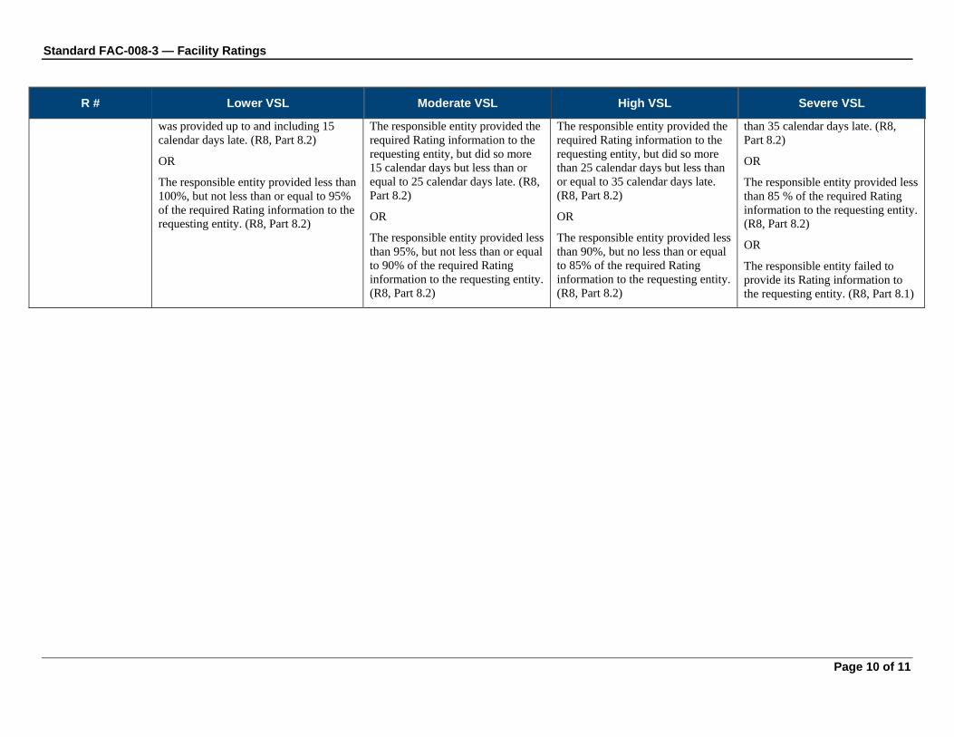
Standard FAC-008-3 — Facility Ratings
Page 10 of 11
R # Lower VSL Moderate VSL High VSL Severe VSL
was provided up to and including 15 calendar days late. (R8, Part 8.2)
OR
The responsible entity provided less than 100%, but not less than or equal to 95% of the required Rating information to the requesting entity. (R8, Part 8.2)
The responsible entity provided the required Rating information to the requesting entity, but did so more 15 calendar days but less than or equal to 25 calendar days late. (R8, Part 8.2)
OR
The responsible entity provided less than 95%, but not less than or equal to 90% of the required Rating information to the requesting entity. (R8, Part 8.2)
The responsible entity provided the required Rating information to the requesting entity, but did so more than 25 calendar days but less than or equal to 35 calendar days late. (R8, Part 8.2)
OR
The responsible entity provided less than 90%, but no less than or equal to 85% of the required Rating information to the requesting entity. (R8, Part 8.2)
than 35 calendar days late. (R8, Part 8.2)
OR
The responsible entity provided less than 85 % of the required Rating information to the requesting entity. (R8, Part 8.2)
OR
The responsible entity failed to provide its Rating information to the requesting entity. (R8, Part 8.1)

Standard FAC-008-3 — Facility Ratings
Page 11 of 11
E. Regional Variances None.
F. Associated Documents
Version History
Version Date Action Change Tracking
1 Feb 7, 2006 Approved by Board of Trustees
New
1 Mar 16, 2007 Approved by FERC New
2 May 12, 2010 Approved by Board of Trustees
Complete Revision, merging FAC_008-1 and FAC-009-1 under Project 2009-06 and address directives from Order 693
3 May 24, 2011 Addition of Requirement R8 Project 2009-06 Expansion to address third directive from Order 693
3 May 24, 2011 Adopted by NERC Board of Trustees
3 November 17, 2011
FERC Order issued approving FAC-008-3
3 May 17, 2012 FERC Order issued directing the VRF for Requirement R2 be changed from “Lower” to “Medium”
3 February 7, 2013
R4 and R5 and associated elements approved by NERC Board of Trustees for retirement as part of the Paragraph 81 project (Project 2013-02) pending applicable regulatory approval.

Standard FAC-010-2.1 — System Operating Limits Methodology for the Planning Horizon
Page 1 of 9
A. Introduction 1. Title: System Operating Limits Methodology for the Planning Horizon
2. Number: FAC-010-2.1
3. Purpose: To ensure that System Operating Limits (SOLs) used in the reliable planning of the Bulk Electric System (BES) are determined based on an established methodology or methodologies.
4. Applicability
4.1. Planning Authority
5. Effective Date: April 19, 2010
B. Requirements R1. The Planning Authority shall have a documented SOL Methodology for use in developing
SOLs within its Planning Authority Area. This SOL Methodology shall:
R1.1. Be applicable for developing SOLs used in the planning horizon.
R1.2. State that SOLs shall not exceed associated Facility Ratings.
R1.3. Include a description of how to identify the subset of SOLs that qualify as IROLs.
R2. The Planning Authority’s SOL Methodology shall include a requirement that SOLs provide BES performance consistent with the following:
R2.1. In the pre-contingency state and with all Facilities in service, the BES shall demonstrate transient, dynamic and voltage stability; all Facilities shall be within their Facility Ratings and within their thermal, voltage and stability limits. In the determination of SOLs, the BES condition used shall reflect expected system conditions and shall reflect changes to system topology such as Facility outages.
R2.2. Following the single Contingencies1 identified in Requirement 2.2.1 through Requirement 2.2.3, the system shall demonstrate transient, dynamic and voltage stability; all Facilities shall be operating within their Facility Ratings and within their thermal, voltage and stability limits; and Cascading or uncontrolled separation shall not occur.
R2.2.1. Single line to ground or three-phase Fault (whichever is more severe), with Normal Clearing, on any Faulted generator, line, transformer, or shunt device.
R2.2.2. Loss of any generator, line, transformer, or shunt device without a Fault.
R2.2.3. Single pole block, with Normal Clearing, in a monopolar or bipolar high voltage direct current system.
R2.3. Starting with all Facilities in service, the system’s response to a single Contingency, may include any of the following:
R2.3.1. Planned or controlled interruption of electric supply to radial customers or some local network customers connected to or supplied by the Faulted Facility or by the affected area.
1 The Contingencies identified in R2.2.1 through R2.2.3 are the minimum contingencies that must be studied but are not necessarily the only Contingencies that should be studied.

Standard FAC-010-2.1 — System Operating Limits Methodology for the Planning Horizon
Page 2 of 9
R2.3.2. System reconfiguration through manual or automatic control or protection actions.
R2.4. To prepare for the next Contingency, system adjustments may be made, including changes to generation, uses of the transmission system, and the transmission system topology.
R2.5. Starting with all Facilities in service and following any of the multiple Contingencies identified in Reliability Standard TPL-003 the system shall demonstrate transient, dynamic and voltage stability; all Facilities shall be operating within their Facility Ratings and within their thermal, voltage and stability limits; and Cascading or uncontrolled separation shall not occur.
R2.6. In determining the system’s response to any of the multiple Contingencies, identified in Reliability Standard TPL-003, in addition to the actions identified in R2.3.1 and R2.3.2, the following shall be acceptable:
R2.6.1. Planned or controlled interruption of electric supply to customers (load shedding), the planned removal from service of certain generators, and/or the curtailment of contracted Firm (non-recallable reserved) electric power Transfers.
R3. The Planning Authority’s methodology for determining SOLs, shall include, as a minimum, a description of the following, along with any reliability margins applied for each:
R3.1. Study model (must include at least the entire Planning Authority Area as well as the critical modeling details from other Planning Authority Areas that would impact the Facility or Facilities under study).
R3.2. Selection of applicable Contingencies.
R3.3. Level of detail of system models used to determine SOLs.
R3.4. Allowed uses of Special Protection Systems or Remedial Action Plans.
R3.5. Anticipated transmission system configuration, generation dispatch and Load level.
R3.6. Criteria for determining when violating a SOL qualifies as an Interconnection Reliability Operating Limit (IROL) and criteria for developing any associated IROL Tv.
R4. The Planning Authority shall issue its SOL Methodology, and any change to that methodology, to all of the following prior to the effectiveness of the change:
R4.1. Each adjacent Planning Authority and each Planning Authority that indicated it has a reliability-related need for the methodology.
R4.2. Each Reliability Coordinator and Transmission Operator that operates any portion of the Planning Authority’s Planning Authority Area.
R4.3. Each Transmission Planner that works in the Planning Authority’s Planning Authority Area.
R5. If a recipient of the SOL Methodology provides documented technical comments on the methodology, the Planning Authority shall provide a documented response to that recipient within 45 calendar days of receipt of those comments. The response shall indicate whether a change will be made to the SOL Methodology and, if no change will be made to that SOL Methodology, the reason why. (Retirement approved by NERC BOT pending applicable regulatory approval.)

Standard FAC-010-2.1 — System Operating Limits Methodology for the Planning Horizon
Page 3 of 9
C. Measures M1. The Planning Authority’s SOL Methodology shall address all of the items listed in
Requirement 1 through Requirement 3.
M2. The Planning Authority shall have evidence it issued its SOL Methodology and any changes to that methodology, including the date they were issued, in accordance with Requirement 4.
If the recipient of the SOL Methodology provides documented comments on its technical review of that SOL methodology, the Planning Authority that distributed that SOL Methodology shall have evidence that it provided a written response to that commenter within 45 calendar days of receipt of those comments in accordance with Requirement 5. (Retirement approved by NERC BOT pending applicable regulatory approval.)
D. Compliance 1. Compliance Monitoring Process
1.1. Compliance Monitoring Responsibility
Regional Reliability Organization
1.2. Compliance Monitoring Period and Reset Time Frame
Each Planning Authority shall self-certify its compliance to the Compliance Monitor at least once every three years. New Planning Authorities shall demonstrate compliance through an on-site audit conducted by the Compliance Monitor within the first year that it commences operation. The Compliance Monitor shall also conduct an on-site audit once every nine years and an investigation upon complaint to assess performance.
The Performance-Reset Period shall be twelve months from the last non-compliance.
1.3. Data Retention
The Planning Authority shall keep all superseded portions to its SOL Methodology for 12 months beyond the date of the change in that methodology and shall keep all documented comments on its SOL Methodology and associated responses for three years. In addition, entities found non-compliant shall keep information related to the non-compliance until found compliant. (Deleted text retired-Retirement approved by NERC BOT pending applicable regulatory approval.)
The Compliance Monitor shall keep the last audit and all subsequent compliance records.
1.4. Additional Compliance Information
The Planning Authority shall make the following available for inspection during an on-site audit by the Compliance Monitor or within 15 business days of a request as part of an investigation upon complaint:
1.4.1 SOL Methodology.
Documented comments provided by a recipient of the SOL Methodology on its technical review of a SOL Methodology, and the associated responses. (Retirement approved by NERC BOT pending applicable regulatory approval.)
1.4.2 Superseded portions of its SOL Methodology that had been made within the past 12 months.
1.4.3 Evidence that the SOL Methodology and any changes to the methodology that occurred within the past 12 months were issued to all required entities.
2. Levels of Non-Compliance for Western Interconnection: (To be replaced with VSLs once developed and approved by WECC)

Standard FAC-010-2.1 — System Operating Limits Methodology for the Planning Horizon
Page 4 of 9
2.1. Level 1: There shall be a level one non-compliance if either of the following conditions exists:
2.1.1 The SOL Methodology did not include a statement indicating that Facility Ratings shall not be exceeded.
2.1.2 No evidence of responses to a recipient’s comments on the SOL Methodology. (Retirement approved by NERC BOT pending applicable regulatory approval.)
2.2. Level 2: The SOL Methodology did not include a requirement to address all of the elements in R2.1 through R2.3 and E1.
2.3. Level 3: There shall be a level three non-compliance if any of the following conditions exists:
2.3.1 The SOL Methodology did not include a statement indicating that Facility Ratings shall not be exceeded and the methodology did not include evaluation of system response to one of the three types of single Contingencies identified in R2.2.
2.3.2 The SOL Methodology did not include a statement indicating that Facility Ratings shall not be exceeded and the methodology did not include evaluation of system response to two of the seven types of multiple Contingencies identified in E1.1.
2.3.3 The System Operating Limits Methodology did not include a statement indicating that Facility Ratings shall not be exceeded and the methodology did not address two of the six required topics in R3.
2.4. Level 4: The SOL Methodology was not issued to all required entities in accordance with R4

Standard FAC-010-2.1 — System Operating Limits Methodology for the Planning Horizon
Page 5 of 9
3. Violation Severity Levels:
Requirement Lower Moderate High Severe
R1 Not applicable. The Planning Authority has a documented SOL Methodology for use in developing SOLs within its Planning Authority Area, but it does not address R1.2
The Planning Authority has a documented SOL Methodology for use in developing SOLs within its Planning Authority Area, but it does not address R1.3.
The Planning Authority has a documented SOL Methodology for use in developing SOLs within its Planning Authority Area, but it does not address R1.1.
OR
The Planning Authority has no documented SOL Methodology for use in developing SOLs within its Planning Authority Area.
R2
The Planning Authority’s SOL Methodology requires that SOLs are set to meet BES performance following single and multiple contingencies, but does not address the pre-contingency state (R2.1)
The Planning Authority’s SOL Methodology requires that SOLs are set to meet BES performance in the pre-contingency state and following single contingencies, but does not address multiple contingencies. (R2.5-R2.6)
The Planning Authority’s SOL Methodology requires that SOLs are set to meet BES performance in the pre-contingency state and following multiple contingencies, but does not meet the performance for response to single contingencies. (R2.2 –R2.4)
The Planning Authority’s SOL Methodology requires that SOLs are set to meet BES performance in the pre-contingency state but does not require that SOLs be set to meet the BES performance specified for response to single contingencies (R2.2-R2.4) and does not require that SOLs be set to meet the BES performance specified for response to multiple contingencies. (R2.5-R2.6)
R3
The Planning Authority has a methodology for determining SOLs that includes a description for all but one of the following: R3.1 through R3.6.
The Planning Authority has a methodology for determining SOLs that includes a description for all but two of the following: R3.1 through R3.6.
The Planning Authority has a methodology for determining SOLs that includes a description for all but three of the following: R3.1 through R3.6.
The Planning Authority has a methodology for determining SOLs that is missing a description of four or more of the following: R3.1 through R3.6.
R4 One or both of the following:
The Planning Authority issued its SOL Methodology and changes
One of the following:
The Planning Authority issued its SOL Methodology and changes
One of the following:
The Planning Authority issued its SOL Methodology and changes
One of the following:
The Planning Authority failed to issue its SOL Methodology and

Standard FAC-010-2.1 — System Operating Limits Methodology for the Planning Horizon
Page 6 of 9
Requirement Lower Moderate High Severe to that methodology to all but one of the required entities.
For a change in methodology, the changed methodology was provided up to 30 calendar days after the effectiveness of the change.
to that methodology to all but one of the required entities AND for a change in methodology, the changed methodology was provided 30 calendar days or more, but less than 60 calendar days after the effectiveness of the change.
OR
The Planning Authority issued its SOL Methodology and changes to that methodology to all but two of the required entities AND for a change in methodology, the changed methodology was provided up to 30 calendar days after the effectiveness of the change.
to that methodology to all but one of the required entities AND for a change in methodology, the changed methodology was provided 60 calendar days or more, but less than 90 calendar days after the effectiveness of the change.
OR
The Planning Authority issued its SOL Methodology and changes to that methodology to all but two of the required entities AND for a change in methodology, the changed methodology was provided 30 calendar days or more, but less than 60 calendar days after the effectiveness of the change.
OR
The Planning Authority issued its SOL Methodology and changes to that methodology to all but three of the required entities AND for a change in methodology, the changed methodology was provided up to 30 calendar days after the effectiveness of the change.
changes to that methodology to more than three of the required entities.
The Planning Authority issued its SOL Methodology and changes to that methodology to all but one of the required entities AND for a change in methodology, the changed methodology was provided 90 calendar days or more after the effectiveness of the change.
OR
The Planning Authority issued its SOL Methodology and changes to that methodology to all but two of the required entities AND for a change in methodology, the changed methodology was provided 60 calendar days or more, but less than 90 calendar days after the effectiveness of the change.
OR
The Planning Authority issued its SOL Methodology and changes to that methodology to all but three of the required entities AND for a change in methodology, the changed methodology was provided 30 calendar days or more, but less than 60 calendar days after the effectiveness of the change.
The Planning Authority issued its SOL Methodology and changes to that methodology to all but

Standard FAC-010-2.1 — System Operating Limits Methodology for the Planning Horizon
Page 7 of 9
Requirement Lower Moderate High Severe four of the required entities AND for a change in methodology, the changed methodology was provided up to 30 calendar days after the effectiveness of the change.
R5
(Retirement approved by NERC BOT pending applicable regulatory approval.)
The Planning Authority received documented technical comments on its SOL Methodology and provided a complete response in a time period that was longer than 45 calendar days but less than 60 calendar days.
The Planning Authority received documented technical comments on its SOL Methodology and provided a complete response in a time period that was 60 calendar days or longer but less than 75 calendar days.
The Planning Authority received documented technical comments on its SOL Methodology and provided a complete response in a time period that was 75 calendar days or longer but less than 90 calendar days.
OR
The Planning Authority’s response to documented technical comments on its SOL Methodology indicated that a change will not be made, but did not include an explanation of why the change will not be made.
The Planning Authority received documented technical comments on its SOL Methodology and provided a complete response in a time period that was 90 calendar days or longer.
OR
The Planning Authority’s response to documented technical comments on its SOL Methodology did not indicate whether a change will be made to the SOL Methodology.

Standard FAC-010-2.1 — System Operating Limits Methodology for the Planning Horizon
Page 8 of 9
E. Regional Differences 1. The following Interconnection-wide Regional Difference shall be applicable in the Western
Interconnection:
1.1. As governed by the requirements of R2.5 and R2.6, starting with all Facilities in service, shall require the evaluation of the following multiple Facility Contingencies when establishing SOLs:
1.1.1 Simultaneous permanent phase to ground Faults on different phases of each of two adjacent transmission circuits on a multiple circuit tower, with Normal Clearing. If multiple circuit towers are used only for station entrance and exit purposes, and if they do not exceed five towers at each station, then this condition is an acceptable risk and therefore can be excluded.
1.1.2 A permanent phase to ground Fault on any generator, transmission circuit, transformer, or bus section with Delayed Fault Clearing except for bus sectionalizing breakers or bus-tie breakers addressed in E1.1.7
1.1.3 Simultaneous permanent loss of both poles of a direct current bipolar Facility without an alternating current Fault.
1.1.4 The failure of a circuit breaker associated with a Special Protection System to operate when required following: the loss of any element without a Fault; or a permanent phase to ground Fault, with Normal Clearing, on any transmission circuit, transformer or bus section.
1.1.5 A non-three phase Fault with Normal Clearing on common mode Contingency of two adjacent circuits on separate towers unless the event frequency is determined to be less than one in thirty years.
1.1.6 A common mode outage of two generating units connected to the same switchyard, not otherwise addressed by FAC-010.
1.1.7 The loss of multiple bus sections as a result of failure or delayed clearing of a bus tie or bus sectionalizing breaker to clear a permanent Phase to Ground Fault.
1.2. SOLs shall be established such that for multiple Facility Contingencies in E1.1.1 through E1.1.5 operation within the SOL shall provide system performance consistent with the following:
1.2.1 All Facilities are operating within their applicable Post-Contingency thermal, frequency and voltage limits.
1.2.2 Cascading does not occur.
1.2.3 Uncontrolled separation of the system does not occur.
1.2.4 The system demonstrates transient, dynamic and voltage stability.
1.2.5 Depending on system design and expected system impacts, the controlled interruption of electric supply to customers (load shedding), the planned removal from service of certain generators, and/or the curtailment of contracted firm (non-recallable reserved) electric power transfers may be necessary to maintain the overall security of the interconnected transmission systems.
1.2.6 Interruption of firm transfer, Load or system reconfiguration is permitted through manual or automatic control or protection actions.

Standard FAC-010-2.1 — System Operating Limits Methodology for the Planning Horizon
Page 9 of 9
1.2.7 To prepare for the next Contingency, system adjustments are permitted, including changes to generation, Load and the transmission system topology when determining limits.
1.3. SOLs shall be established such that for multiple Facility Contingencies in E1.1.6 through E1.1.7 operation within the SOL shall provide system performance consistent with the following with respect to impacts on other systems:
1.3.1 Cascading does not occur.
1.4. The Western Interconnection may make changes (performance category adjustments) to the Contingencies required to be studied and/or the required responses to Contingencies for specific facilities based on actual system performance and robust design. Such changes will apply in determining SOLs.
Version History
Version Date Action Change Tracking 1 November 1,
2006 Adopted by Board of Trustees New
1 November 1, 2006
Fixed typo. Removed the word “each” from the 1st sentence of section D.1.3, Data Retention.
01/11/07
2 June 24, 2008 Adopted by Board of Trustees; FERC Order 705
Revised
2 Changed the effective date to July 1, 2008 Changed “Cascading Outage” to “Cascading” Replaced Levels of Non-compliance with Violation Severity Levels
Revised
2 January 22, 2010
Updated effective date and footer to April 29, 2009 based on the March 20, 2009 FERC Order
Update
2.1 November 5, 2009
Adopted by the Board of Trustees — errata change Section E1.1 modified to reflect the renumbering of requirements R2.4 and R2.5 from FAC-010-1 to R2.5 and R2.6 in FAC-010-2.
Errata
2.1 April 19, 2010 FERC Approved — errata change Section E1.1 modified to reflect the renumbering of requirements R2.4 and R2.5 from FAC-010-1 to R2.5 and R2.6 in FAC-010-2.
Errata
2.1 February 7, 2013
R5 and associated elements approved by NERC Board of Trustees for retirement as part of the Paragraph 81 project (Project 2013-02) pending applicable regulatory approval.

Standard FAC-011-2 — System Operating Limits Methodology for the Operations Horizon
Page 1 of 9
A. Introduction 1. Title: System Operating Limits Methodology for the Operations Horizon
2. Number: FAC-011-2
3. Purpose: To ensure that System Operating Limits (SOLs) used in the reliable operation of the Bulk Electric System (BES) are determined based on an established methodology or methodologies.
4. Applicability
4.1. Reliability Coordinator
5. Effective Date: April 29, 2009
B. Requirements R1. The Reliability Coordinator shall have a documented methodology for use in developing SOLs
(SOL Methodology) within its Reliability Coordinator Area. This SOL Methodology shall:
R1.1. Be applicable for developing SOLs used in the operations horizon.
R1.2. State that SOLs shall not exceed associated Facility Ratings.
R1.3. Include a description of how to identify the subset of SOLs that qualify as IROLs.
R2. The Reliability Coordinator’s SOL Methodology shall include a requirement that SOLs provide BES performance consistent with the following:
R2.1. In the pre-contingency state, the BES shall demonstrate transient, dynamic and voltage stability; all Facilities shall be within their Facility Ratings and within their thermal, voltage and stability limits. In the determination of SOLs, the BES condition used shall reflect current or expected system conditions and shall reflect changes to system topology such as Facility outages.
R2.2. Following the single Contingencies1 identified in Requirement 2.2.1 through Requirement 2.2.3, the system shall demonstrate transient, dynamic and voltage stability; all Facilities shall be operating within their Facility Ratings and within their thermal, voltage and stability limits; and Cascading or uncontrolled separation shall not occur.
R2.2.1. Single line to ground or 3-phase Fault (whichever is more severe), with Normal Clearing, on any Faulted generator, line, transformer, or shunt device.
R2.2.2. Loss of any generator, line, transformer, or shunt device without a Fault.
R2.2.3. Single pole block, with Normal Clearing, in a monopolar or bipolar high voltage direct current system.
R2.3. In determining the system’s response to a single Contingency, the following shall be acceptable:
R2.3.1. Planned or controlled interruption of electric supply to radial customers or some local network customers connected to or supplied by the Faulted Facility or by the affected area.
1 The Contingencies identified in FAC-011 R2.2.1 through R2.2.3 are the minimum contingencies that must be studied but are not necessarily the only Contingencies that should be studied.

Standard FAC-011-2 — System Operating Limits Methodology for the Operations Horizon
Page 2 of 9
R2.3.2. Interruption of other network customers, (a) only if the system has already been adjusted, or is being adjusted, following at least one prior outage, or (b) if the real-time operating conditions are more adverse than anticipated in the corresponding studies
R2.3.3. System reconfiguration through manual or automatic control or protection actions.
R2.4. To prepare for the next Contingency, system adjustments may be made, including changes to generation, uses of the transmission system, and the transmission system topology.
R3. The Reliability Coordinator’s methodology for determining SOLs, shall include, as a minimum, a description of the following, along with any reliability margins applied for each:
R3.1. Study model (must include at least the entire Reliability Coordinator Area as well as the critical modeling details from other Reliability Coordinator Areas that would impact the Facility or Facilities under study.)
R3.2. Selection of applicable Contingencies
R3.3. A process for determining which of the stability limits associated with the list of multiple contingencies (provided by the Planning Authority in accordance with FAC-014 Requirement 6) are applicable for use in the operating horizon given the actual or expected system conditions.
R3.3.1. This process shall address the need to modify these limits, to modify the list of limits, and to modify the list of associated multiple contingencies.
R3.4. Level of detail of system models used to determine SOLs.
R3.5. Allowed uses of Special Protection Systems or Remedial Action Plans.
R3.6. Anticipated transmission system configuration, generation dispatch and Load level
R3.7. Criteria for determining when violating a SOL qualifies as an Interconnection Reliability Operating Limit (IROL) and criteria for developing any associated IROL Tv.
R4. The Reliability Coordinator shall issue its SOL Methodology and any changes to that methodology, prior to the effectiveness of the Methodology or of a change to the Methodology, to all of the following:
R4.1. Each adjacent Reliability Coordinator and each Reliability Coordinator that indicated it has a reliability-related need for the methodology.
R4.2. Each Planning Authority and Transmission Planner that models any portion of the Reliability Coordinator’s Reliability Coordinator Area.
R4.3. Each Transmission Operator that operates in the Reliability Coordinator Area.
R5. If a recipient of the SOL Methodology provides documented technical comments on the methodology, the Reliability Coordinator shall provide a documented response to that recipient within 45 calendar days of receipt of those comments. The response shall indicate whether a change will be made to the SOL Methodology and, if no change will be made to that SOL Methodology, the reason why. (Retirement approved by NERC BOT pending applicable regulatory approval.)

Standard FAC-011-2 — System Operating Limits Methodology for the Operations Horizon
Page 3 of 9
C. Measures M1. The Reliability Coordinator’s SOL Methodology shall address all of the items listed in
Requirement 1 through Requirement 3.
M2. The Reliability Coordinator shall have evidence it issued its SOL Methodology, and any changes to that methodology, including the date they were issued, in accordance with Requirement 4.
M3. If the recipient of the SOL Methodology provides documented comments on its technical review of that SOL methodology, the Reliability Coordinator that distributed that SOL Methodology shall have evidence that it provided a written response to that commenter within 45 calendar days of receipt of those comments in accordance with Requirement 5. (Retirement approved by NERC BOT pending applicable regulatory approval.)
D. Compliance
1. Compliance Monitoring Process
1.1. Compliance Monitoring Responsibility
Regional Reliability Organization
1.2. Compliance Monitoring Period and Reset Time Frame
Each Reliability Coordinator shall self-certify its compliance to the Compliance Monitor at least once every three years. New Reliability Authorities shall demonstrate compliance through an on-site audit conducted by the Compliance Monitor within the first year that it commences operation. The Compliance Monitor shall also conduct an on-site audit once every nine years and an investigation upon complaint to assess performance.
The Performance-Reset Period shall be twelve months from the last non-compliance.
1.3. Data Retention
The Reliability Coordinator shall keep all superseded portions to its SOL Methodology for 12 months beyond the date of the change in that methodology and shall keep all documented comments on its SOL Methodology and associated responses for three years. In addition, entities found non-compliant shall keep information related to the non-compliance until found compliant. (Deleted text retired-Retirement approved by NERC BOT pending applicable regulatory approval.)
The Compliance Monitor shall keep the last audit and all subsequent compliance records.
1.4. Additional Compliance Information
The Reliability Coordinator shall make the following available for inspection during an on-site audit by the Compliance Monitor or within 15 business days of a request as part of an investigation upon complaint:
1.4.1 SOL Methodology.
1.4.2 Documented comments provided by a recipient of the SOL Methodology on its technical review of a SOL Methodology, and the associated responses. (Retirement approved by NERC BOT pending applicable regulatory approval.)
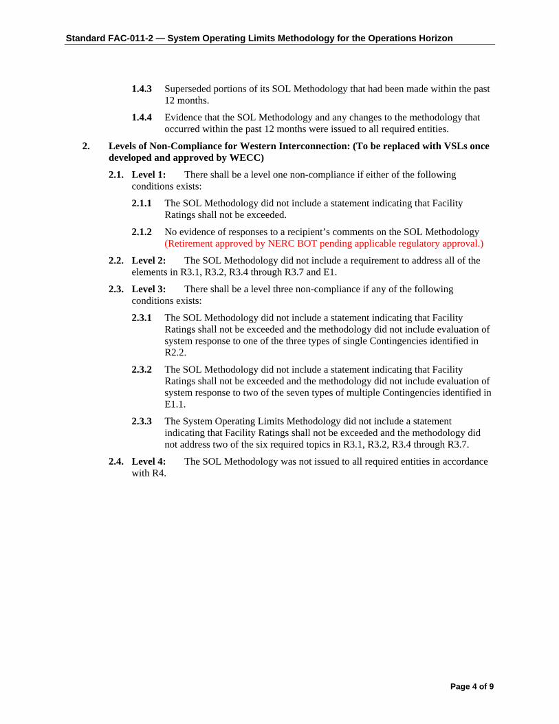
Standard FAC-011-2 — System Operating Limits Methodology for the Operations Horizon
Page 4 of 9
1.4.3 Superseded portions of its SOL Methodology that had been made within the past 12 months.
1.4.4 Evidence that the SOL Methodology and any changes to the methodology that occurred within the past 12 months were issued to all required entities.
2. Levels of Non-Compliance for Western Interconnection: (To be replaced with VSLs once developed and approved by WECC)
2.1. Level 1: There shall be a level one non-compliance if either of the following conditions exists:
2.1.1 The SOL Methodology did not include a statement indicating that Facility Ratings shall not be exceeded.
2.1.2 No evidence of responses to a recipient’s comments on the SOL Methodology (Retirement approved by NERC BOT pending applicable regulatory approval.)
2.2. Level 2: The SOL Methodology did not include a requirement to address all of the elements in R3.1, R3.2, R3.4 through R3.7 and E1.
2.3. Level 3: There shall be a level three non-compliance if any of the following conditions exists:
2.3.1 The SOL Methodology did not include a statement indicating that Facility Ratings shall not be exceeded and the methodology did not include evaluation of system response to one of the three types of single Contingencies identified in R2.2.
2.3.2 The SOL Methodology did not include a statement indicating that Facility Ratings shall not be exceeded and the methodology did not include evaluation of system response to two of the seven types of multiple Contingencies identified in E1.1.
2.3.3 The System Operating Limits Methodology did not include a statement indicating that Facility Ratings shall not be exceeded and the methodology did not address two of the six required topics in R3.1, R3.2, R3.4 through R3.7.
2.4. Level 4: The SOL Methodology was not issued to all required entities in accordance with R4.
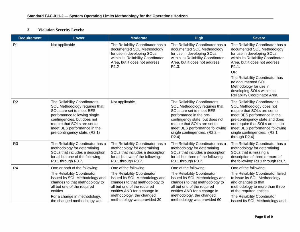
Standard FAC-011-2 — System Operating Limits Methodology for the Operations Horizon
Page 5 of 9
3. Violation Severity Levels:
Requirement Lower Moderate High Severe
R1 Not applicable. The Reliability Coordinator has a documented SOL Methodology for use in developing SOLs within its Reliability Coordinator Area, but it does not address R1.2
The Reliability Coordinator has a documented SOL Methodology for use in developing SOLs within its Reliability Coordinator Area, but it does not address R1.3.
The Reliability Coordinator has a documented SOL Methodology for use in developing SOLs within its Reliability Coordinator Area, but it does not address R1.1.
OR
The Reliability Coordinator has no documented SOL Methodology for use in developing SOLs within its Reliability Coordinator Area.
R2 The Reliability Coordinator‘s SOL Methodology requires that SOLs are set to meet BES performance following single contingencies, but does not require that SOLs are set to meet BES performance in the pre-contingency state. (R2.1)
Not applicable. The Reliability Coordinator‘s SOL Methodology requires that SOLs are set to meet BES performance in the pre-contingency state, but does not require that SOLs are set to meet BES performance following single contingencies. (R2.2 – R2.4)
The Reliability Coordinator’s SOL Methodology does not require that SOLs are set to meet BES performance in the pre-contingency state and does not require that SOLs are set to meet BES performance following single contingencies. (R2.1 through R2.4)
R3
The Reliability Coordinator has a methodology for determining SOLs that includes a description for all but one of the following: R3.1 through R3.7.
The Reliability Coordinator has a methodology for determining SOLs that includes a description for all but two of the following: R3.1 through R3.7.
The Reliability Coordinator has a methodology for determining SOLs that includes a description for all but three of the following: R3.1 through R3.7.
The Reliability Coordinator has a methodology for determining SOLs that is missing a description of three or more of the following: R3.1 through R3.7.
R4 One or both of the following:
The Reliability Coordinator issued its SOL Methodology and changes to that methodology to all but one of the required entities.
For a change in methodology, the changed methodology was
One of the following:
The Reliability Coordinator issued its SOL Methodology and changes to that methodology to all but one of the required entities AND for a change in methodology, the changed methodology was provided 30
One of the following:
The Reliability Coordinator issued its SOL Methodology and changes to that methodology to all but one of the required entities AND for a change in methodology, the changed methodology was provided 60
One of the following:
The Reliability Coordinator failed to issue its SOL Methodology and changes to that methodology to more than three of the required entities.
The Reliability Coordinator issued its SOL Methodology and

Standard FAC-011-2 — System Operating Limits Methodology for the Operations Horizon
Page 6 of 9
Requirement Lower Moderate High Severe provided up to 30 calendar days after the effectiveness of the change.
calendar days or more, but less than 60 calendar days after the effectiveness of the change.
OR
The Reliability Coordinator issued its SOL Methodology and changes to that methodology to all but two of the required entities AND for a change in methodology, the changed methodology was provided up to 30 calendar days after the effectiveness of the change.
calendar days or more, but less than 90 calendar days after the effectiveness of the change.
OR
The Reliability Coordinator issued its SOL Methodology and changes to that methodology to all but two of the required entities AND for a change in methodology, the changed methodology was provided 30 calendar days or more, but less than 60 calendar days after the effectiveness of the change.
OR
The Reliability Coordinator issued its SOL Methodology and changes to that methodology to all but three of the required entities AND for a change in methodology, the changed methodology was provided up to 30 calendar days after the effectiveness of the change.
changes to that methodology to all but one of the required entities AND for a change in methodology, the changed methodology was provided 90 calendar days or more after the effectiveness of the change.
OR
The Reliability Coordinator issued its SOL Methodology and changes to that methodology to all but two of the required entities AND for a change in methodology, the changed methodology was provided 60 calendar days or more, but less than 90 calendar days after the effectiveness of the change.
OR
The Reliability Coordinator issued its SOL Methodology and changes to that methodology to all but three of the required entities AND for a change in methodology, the changed methodology was provided 30 calendar days or more, but less than 60 calendar days after the effectiveness of the change.
OR
The Reliability Coordinator issued its SOL Methodology and changes to that methodology to all but four of the required entities AND for a change in methodology, the changed methodology was provided up to

Standard FAC-011-2 — System Operating Limits Methodology for the Operations Horizon
Page 7 of 9
Requirement Lower Moderate High Severe 30 calendar days after the effectiveness of the change.
R5
(Retirement approved by NERC BOT pending applicable regulatory approval.)
The Reliability Coordinator received documented technical comments on its SOL Methodology and provided a complete response in a time period that was longer than 45 calendar days but less than 60 calendar days.
The Reliability Coordinator received documented technical comments on its SOL Methodology and provided a complete response in a time period that was 60 calendar days or longer but less than 75 calendar days.
The Reliability Coordinator received documented technical comments on its SOL Methodology and provided a complete response in a time period that was 75 calendar days or longer but less than 90 calendar days.
OR
The Reliability Coordinator’s response to documented technical comments on its SOL Methodology indicated that a change will not be made, but did not include an explanation of why the change will not be made.
The Reliability Coordinator received documented technical comments on its SOL Methodology and provided a complete response in a time period that was 90 calendar days or longer.
OR
The Reliability Coordinator’s response to documented technical comments on its SOL Methodology did not indicate whether a change will be made to the SOL Methodology.

Standard FAC-011-2 — System Operating Limits Methodology for the Operations Horizon
Page 8 of 9
Regional Differences 1. The following Interconnection-wide Regional Difference shall be applicable in the Western
Interconnection:
1.1. As governed by the requirements of R3.3, starting with all Facilities in service, shall require the evaluation of the following multiple Facility Contingencies when establishing SOLs:
1.1.1 Simultaneous permanent phase to ground Faults on different phases of each of two adjacent transmission circuits on a multiple circuit tower, with Normal Clearing. If multiple circuit towers are used only for station entrance and exit purposes, and if they do not exceed five towers at each station, then this condition is an acceptable risk and therefore can be excluded.
1.1.2 A permanent phase to ground Fault on any generator, transmission circuit, transformer, or bus section with Delayed Fault Clearing except for bus sectionalizing breakers or bus-tie breakers addressed in E1.1.7
1.1.3 Simultaneous permanent loss of both poles of a direct current bipolar Facility without an alternating current Fault.
1.1.4 The failure of a circuit breaker associated with a Special Protection System to operate when required following: the loss of any element without a Fault; or a permanent phase to ground Fault, with Normal Clearing, on any transmission circuit, transformer or bus section.
1.1.5 A non-three phase Fault with Normal Clearing on common mode Contingency of two adjacent circuits on separate towers unless the event frequency is determined to be less than one in thirty years.
1.1.6 A common mode outage of two generating units connected to the same switchyard, not otherwise addressed by FAC-011.
1.1.7 The loss of multiple bus sections as a result of failure or delayed clearing of a bus tie or bus sectionalizing breaker to clear a permanent Phase to Ground Fault.
1.2. SOLs shall be established such that for multiple Facility Contingencies in E1.1.1 through E1.1.5 operation within the SOL shall provide system performance consistent with the following:
1.2.1 All Facilities are operating within their applicable Post-Contingency thermal, frequency and voltage limits.
1.2.2 Cascading does not occur.
1.2.3 Uncontrolled separation of the system does not occur.
1.2.4 The system demonstrates transient, dynamic and voltage stability.
1.2.5 Depending on system design and expected system impacts, the controlled interruption of electric supply to customers (load shedding), the planned removal from service of certain generators, and/or the curtailment of contracted firm (non-recallable reserved) electric power transfers may be necessary to maintain the overall security of the interconnected transmission systems.
1.2.6 Interruption of firm transfer, Load or system reconfiguration is permitted through manual or automatic control or protection actions.

Standard FAC-011-2 — System Operating Limits Methodology for the Operations Horizon
Page 9 of 9
1.2.7 To prepare for the next Contingency, system adjustments are permitted, including changes to generation, Load and the transmission system topology when determining limits.
1.3. SOLs shall be established such that for multiple Facility Contingencies in E1.1.6 through E1.1.7 operation within the SOL shall provide system performance consistent with the following with respect to impacts on other systems:
1.3.1 Cascading does not occur.
1.4. The Western Interconnection may make changes (performance category adjustments) to the Contingencies required to be studied and/or the required responses to Contingencies for specific facilities based on actual system performance and robust design. Such changes will apply in determining SOLs.
Version History
Version Date Action Change Tracking 1 November 1,
2006 Adopted by Board of Trustees New
2 Changed the effective date to October 1, 2008 Changed “Cascading Outage” to “Cascading” Replaced Levels of Non-compliance with Violation Severity Levels Corrected footnote 1 to reference FAC-011 rather than FAC-010
Revised
2 June 24, 2008 Adopted by Board of Trustees: FERC Order 705
Revised
2 January 22, 2010
Updated effective date and footer to April 29, 2009 based on the March 20, 2009 FERC Order
Update
2 February 7, 2013
R5 and associated elements approved by NERC Board of Trustees for retirement as part of the Paragraph 81 project (Project 2013-02) pending applicable regulatory approval.

Standard FAC-013-2 — Assessment of Transfer Capability for the Near-term Transmission Planning Horizon
Page 1 of 9
A. Introduction 1. Title: Assessment of Transfer Capability for the Near-Term Transmission
Planning Horizon 2. Number: FAC-013-2
3. Purpose: To ensure that Planning Coordinators have a methodology for, and perform an annual assessment to identify potential future Transmission System weaknesses and limiting Facilities that could impact the Bulk Electric System’s (BES) ability to reliably transfer energy in the Near-Term Transmission Planning Horizon.
4. Applicability:
4.1. Planning Coordinators
5. Effective Date: In those jurisdictions where regulatory approval is required, the latter of either the first day of the first calendar quarter twelve months after applicable regulatory approval or the first day of the first calendar quarter six months after MOD-001-1, MOD-028-1, MOD-029-1, and MOD-030-2 are effective.
In those jurisdictions where no regulatory approval is required, the latter of either the first day of the first calendar quarter twelve months after Board of Trustees adoption or the first day of the first calendar quarter six months after MOD-001-1, MOD-028-1, MOD-029-1 and MOD-030-2 are effective.
B. Requirements R1. Each Planning Coordinator shall have a documented methodology it uses to perform an
annual assessment of Transfer Capability in the Near-Term Transmission Planning Horizon (Transfer Capability methodology). The Transfer Capability methodology shall include, at a minimum, the following information: [Violation Risk Factor: Medium] [Time Horizon: Long-term Planning ]
1.1. Criteria for the selection of the transfers to be assessed.
1.2. A statement that the assessment shall respect known System Operating Limits (SOLs).
1.3. A statement that the assumptions and criteria used to perform the assessment are consistent with the Planning Coordinator’s planning practices.
1.4. A description of how each of the following assumptions and criteria used in performing the assessment are addressed:
1.4.1. Generation dispatch, including but not limited to long term planned outages, additions and retirements.
1.4.2. Transmission system topology, including but not limited to long term planned Transmission outages, additions, and retirements.
1.4.3. System demand.
1.4.4. Current approved and projected Transmission uses.
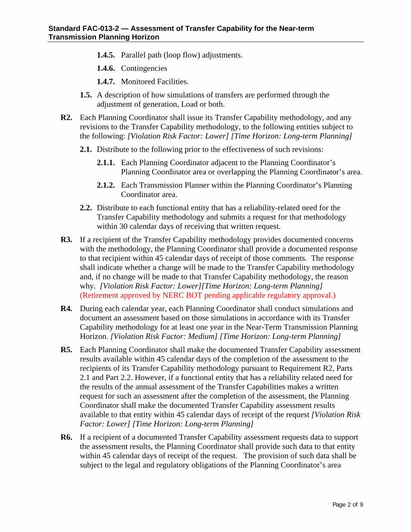
Standard FAC-013-2 — Assessment of Transfer Capability for the Near-term Transmission Planning Horizon
Page 2 of 9
1.4.5. Parallel path (loop flow) adjustments.
1.4.6. Contingencies
1.4.7. Monitored Facilities.
1.5. A description of how simulations of transfers are performed through the adjustment of generation, Load or both.
R2. Each Planning Coordinator shall issue its Transfer Capability methodology, and any revisions to the Transfer Capability methodology, to the following entities subject to the following: [Violation Risk Factor: Lower] [Time Horizon: Long-term Planning]
2.1. Distribute to the following prior to the effectiveness of such revisions:
2.1.1. Each Planning Coordinator adjacent to the Planning Coordinator’s Planning Coordinator area or overlapping the Planning Coordinator’s area.
2.1.2. Each Transmission Planner within the Planning Coordinator’s Planning Coordinator area.
2.2. Distribute to each functional entity that has a reliability-related need for the Transfer Capability methodology and submits a request for that methodology within 30 calendar days of receiving that written request.
R3. If a recipient of the Transfer Capability methodology provides documented concerns with the methodology, the Planning Coordinator shall provide a documented response to that recipient within 45 calendar days of receipt of those comments. The response shall indicate whether a change will be made to the Transfer Capability methodology and, if no change will be made to that Transfer Capability methodology, the reason why. [Violation Risk Factor: Lower][Time Horizon: Long-term Planning] (Retirement approved by NERC BOT pending applicable regulatory approval.)
R4. During each calendar year, each Planning Coordinator shall conduct simulations and document an assessment based on those simulations in accordance with its Transfer Capability methodology for at least one year in the Near-Term Transmission Planning Horizon. [Violation Risk Factor: Medium] [Time Horizon: Long-term Planning]
R5. Each Planning Coordinator shall make the documented Transfer Capability assessment results available within 45 calendar days of the completion of the assessment to the recipients of its Transfer Capability methodology pursuant to Requirement R2, Parts 2.1 and Part 2.2. However, if a functional entity that has a reliability related need for the results of the annual assessment of the Transfer Capabilities makes a written request for such an assessment after the completion of the assessment, the Planning Coordinator shall make the documented Transfer Capability assessment results available to that entity within 45 calendar days of receipt of the request [Violation Risk Factor: Lower] [Time Horizon: Long-term Planning]
R6. If a recipient of a documented Transfer Capability assessment requests data to support the assessment results, the Planning Coordinator shall provide such data to that entity within 45 calendar days of receipt of the request. The provision of such data shall be subject to the legal and regulatory obligations of the Planning Coordinator’s area
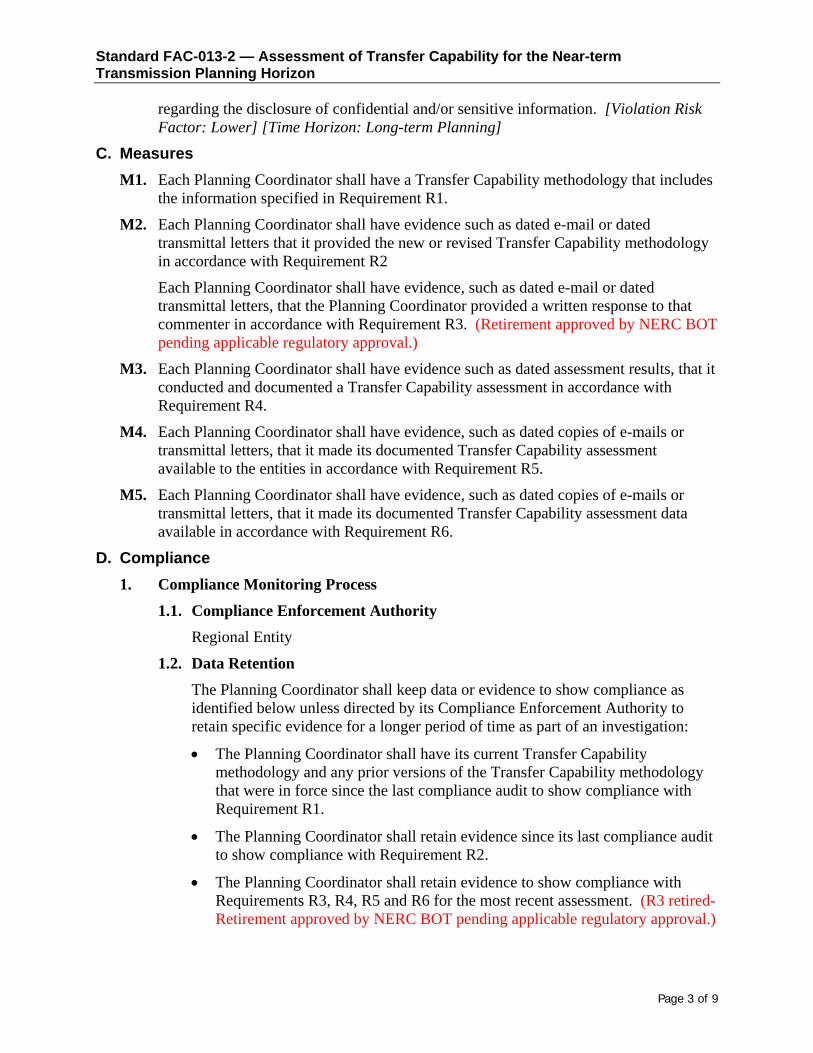
Standard FAC-013-2 — Assessment of Transfer Capability for the Near-term Transmission Planning Horizon
Page 3 of 9
regarding the disclosure of confidential and/or sensitive information. [Violation Risk Factor: Lower] [Time Horizon: Long-term Planning]
C. Measures M1. Each Planning Coordinator shall have a Transfer Capability methodology that includes
the information specified in Requirement R1.
M2. Each Planning Coordinator shall have evidence such as dated e-mail or dated transmittal letters that it provided the new or revised Transfer Capability methodology in accordance with Requirement R2
Each Planning Coordinator shall have evidence, such as dated e-mail or dated transmittal letters, that the Planning Coordinator provided a written response to that commenter in accordance with Requirement R3. (Retirement approved by NERC BOT pending applicable regulatory approval.)
M3. Each Planning Coordinator shall have evidence such as dated assessment results, that it conducted and documented a Transfer Capability assessment in accordance with Requirement R4.
M4. Each Planning Coordinator shall have evidence, such as dated copies of e-mails or transmittal letters, that it made its documented Transfer Capability assessment available to the entities in accordance with Requirement R5.
M5. Each Planning Coordinator shall have evidence, such as dated copies of e-mails or transmittal letters, that it made its documented Transfer Capability assessment data available in accordance with Requirement R6.
D. Compliance 1. Compliance Monitoring Process
1.1. Compliance Enforcement Authority Regional Entity
1.2. Data Retention The Planning Coordinator shall keep data or evidence to show compliance as identified below unless directed by its Compliance Enforcement Authority to retain specific evidence for a longer period of time as part of an investigation:
The Planning Coordinator shall have its current Transfer Capability methodology and any prior versions of the Transfer Capability methodology that were in force since the last compliance audit to show compliance with Requirement R1.
The Planning Coordinator shall retain evidence since its last compliance audit to show compliance with Requirement R2.
The Planning Coordinator shall retain evidence to show compliance with Requirements R3, R4, R5 and R6 for the most recent assessment. (R3 retired-Retirement approved by NERC BOT pending applicable regulatory approval.)

Standard FAC-013-2 — Assessment of Transfer Capability for the Near-term Transmission Planning Horizon
Page 4 of 9
If a Planning Coordinator is found non-compliant, it shall keep information related to the non-compliance until found compliant or for the time periods specified above, whichever is longer.
The Compliance Enforcement Authority shall keep the last audit records and all requested and submitted subsequent audit records.
1.3. Compliance Monitoring and Assessment Processes Compliance Audits
Self-Certifications
Spot Checking
Compliance Violation Investigations
Self-Reporting
Complaints
1.4. Additional Compliance Information None

Standard FAC-013-2 — Assessment of Transfer Capability for the Near-term Transmission Planning Horizon
Page 5 of 9
2. Violation Severity Levels
R # Lower VSL Moderate VSL High VSL Severe VSL
R1 The Planning Coordinator has a Transfer Capability methodology but failed to address one or two of the items listed in Requirement R1, Part 1.4.
The Planning Coordinator has a Transfer Capability methodology, but failed to incorporate one of the following Parts of Requirement R1 into that methodology:
Part 1.1 Part 1.2 Part 1.3 Part 1.5
OR
The Planning Coordinator has a Transfer Capability methodology but failed to address three of the items listed in Requirement R1, Part 1.4.
The Planning Coordinator has a Transfer Capability methodology, but failed to incorporate two of the following Parts of Requirement R1 into that methodology:
Part 1.1 Part 1.2 Part 1.3 Part 1.5
OR
The Planning Coordinator has a Transfer Capability methodology but failed to address four of the items listed in Requirement R1, Part 1.4.
The Planning Coordinator did not have a Transfer Capability methodology.
OR
The Planning Coordinator has a Transfer Capability methodology, but failed to incorporate three or more of the following Parts of Requirement R1 into that methodology:
Part 1.1 Part 1.2 Part 1.3 Part 1.5
OR
The Planning Coordinator has a Transfer Capability methodology but failed to address more than four of the items listed in Requirement R1, Part 1.4.

Standard FAC-013-2 — Assessment of Transfer Capability for the Near-term Transmission Planning Horizon
Page 6 of 9
R2 The Planning Coordinator notified one or more of the parties specified in Requirement R2 of a new or revised Transfer Capability methodology after its implementation, but not more than 30 calendar days after its implementation.
OR
The Planning Coordinator provided the transfer Capability methodology more than 30 calendar days but not more than 60 calendar days after the receipt of a request.
The Planning Coordinator notified one or more of the parties specified in Requirement R2 of a new or revised Transfer Capability methodology more than 30 calendar days after its implementation, but not more than 60 calendar days after its implementation.
OR
The Planning Coordinator provided the Transfer Capability methodology more than 60 calendar days but not more than 90 calendar days after receipt of a request
The Planning Coordinator notified one or more of the parties specified in Requirement R2 of a new or revised Transfer Capability methodology more than 60 calendar days, but not more than 90 calendar days after its implementation.
OR
The Planning Coordinator provided the Transfer Capability methodology more than 90 calendar days but not more than 120 calendar days after receipt of a request.
The Planning Coordinator failed to notify one or more of the parties specified in Requirement R2 of a new or revised Transfer Capability methodology more than 90 calendar days after its implementation.
OR
The Planning Coordinator provided the Transfer Capability methodology more than 120 calendar days after receipt of a request.
R3
(Retirement approved by NERC BOT pending applicable regulatory approval.)
The Planning Coordinator provided a documented response to a documented concern with its Transfer Capability methodology as required in Requirement R3 more than 45 calendar days, but not more than 60 calendar days after receipt of the concern.
The Planning Coordinator provided a documented response to a documented concern with its Transfer Capability methodology as required in Requirement R3 more than 60 calendar days, but not more than 75 calendar days after receipt of the concern.
The Planning Coordinator provided a documented response to a documented concern with its Transfer Capability methodology as required in Requirement R3 more than 75 calendar days, but not more than 90 calendar days after receipt of the concern.
The Planning Coordinator failed to provide a documented response to a documented concern with its Transfer Capability methodology as required in Requirement R3 by more than 90 calendar days after receipt of the concern.
OR
The Planning Coordinator failed to respond to a documented concern with its Transfer Capability methodology.

Standard FAC-013-2 — Assessment of Transfer Capability for the Near-term Transmission Planning Horizon
Page 7 of 9
R4 The Planning Coordinator conducted a Transfer Capability assessment outside the calendar year, but not by more than 30 calendar days.
The Planning Coordinator conducted a Transfer Capability assessment outside the calendar year, by more than 30 calendar days, but not by more than 60 calendar days.
The Planning Coordinator conducted a Transfer Capability assessment outside the calendar year, by more than 60 calendar days, but not by more than 90 calendar days.
The Planning Coordinator failed to conduct a Transfer Capability assessment outside the calendar year by more than 90 calendar days.
OR
The Planning Coordinator failed to conduct a Transfer Capability assessment.

Standard FAC-013-2 — Assessment of Transfer Capability for the Near-term Transmission Planning Horizon
Page 8 of 9
R5
The Planning Coordinator made its documented Transfer Capability assessment available to one or more of the recipients of its Transfer Capability methodology more than 45 calendar days after the requirements of R5,, but not more than 60 calendar days after completion of the assessment.
The Planning Coordinator made its Transfer Capability assessment available to one or more of the recipients of its Transfer Capability methodology more than 60 calendar days after the requirements of R5, but not more than 75 calendar days after completion of the assessment.
The Planning Coordinator made its Transfer Capability assessment available to one or more of the recipients of its Transfer Capability methodology more than 75 calendar days after the requirements of R5, but not more than 90 days after completion of the assessment.
The Planning Coordinator failed to make its documented Transfer Capability assessment available to one or more of the recipients of its Transfer Capability methodology more than 90 days after the requirements of R5.
OR
The Planning Coordinator failed to make its documented Transfer Capability assessment available to any of the recipients of its Transfer Capability methodology under the requirements of R5.
R6 The Planning Coordinator provided the requested data as required in Requirement R6 more than 45 calendar days after receipt of the request for data, but not more than 60 calendar days after the receipt of the request for data.
The Planning Coordinator provided the requested data as required in Requirement R6 more than 60 calendar days after receipt of the request for data, but not more than 75 calendar days after the receipt of the request for data.
The Planning Coordinator provided the requested data as required in Requirement R6 more than 75 calendar days after receipt of the request for data, but not more than 90 calendar days after the receipt of the request for data.
The Planning Coordinator provided the requested data as required in Requirement R6 more than 90 after the receipt of the request for data.
OR
The Planning Coordinator failed to provide the requested data as required in Requirement R6.

Standard FAC-013-2 — Assessment of Transfer Capability for the Near-term Transmission Planning Horizon
Page 9 of 9
E. Regional Variances
None.
F. Associated Documents
Version History Version Date Action Change Tracking
1 08/01/05 1. Changed incorrect use of certain hyphens (-) to “en dash (–).”
2. Lower cased the word “draft” and “drafting team” where appropriate.
3. Changed Anticipated Action #5, page 1, from “30-day” to “Thirty-day.”
4. Added or removed “periods.”
01/20/05
2 01/24/11 Approved by BOT
2 11/17/11 FERC Order issued approving FAC-013-2
2 05/17/12 FERC Order issued directing the VRF’s for Requirements R1. and R4. be changed from “Lower” to “Medium.” FERC Order issued correcting the High and Severe VSL language for R1.
2 02/7/13 R3 and associated elements approved by NERC Board of Trustees for retirement as part of the Paragraph 81 project (Project 2013-02) pending applicable regulatory approval.

Standard FAC-014-2 — Establish and Communicate System Operating Limits
Adopted by Board of Trustees: June 24, 2008 Page 1 of 6 Effective Date: April 29, 2009
A. Introduction 1. Title: Establish and Communicate System Operating Limits
2. Number: FAC-014-2
3. Purpose: To ensure that System Operating Limits (SOLs) used in the reliable planning and operation of the Bulk Electric System (BES) are determined based on an established methodology or methodologies.
4. Applicability
4.1. Reliability Coordinator
4.2. Planning Authority
4.3. Transmission Planner
4.4. Transmission Operator
5. Effective Date: April 29, 2009
B. Requirements R1. The Reliability Coordinator shall ensure that SOLs, including Interconnection Reliability
Operating Limits (IROLs), for its Reliability Coordinator Area are established and that the SOLs (including Interconnection Reliability Operating Limits) are consistent with its SOL Methodology.
R2. The Transmission Operator shall establish SOLs (as directed by its Reliability Coordinator) for its portion of the Reliability Coordinator Area that are consistent with its Reliability Coordinator’s SOL Methodology.
R3. The Planning Authority shall establish SOLs, including IROLs, for its Planning Authority Area that are consistent with its SOL Methodology.
R4. The Transmission Planner shall establish SOLs, including IROLs, for its Transmission Planning Area that are consistent with its Planning Authority’s SOL Methodology.
R5. The Reliability Coordinator, Planning Authority and Transmission Planner shall each provide its SOLs and IROLs to those entities that have a reliability-related need for those limits and provide a written request that includes a schedule for delivery of those limits as follows:
R5.1. The Reliability Coordinator shall provide its SOLs (including the subset of SOLs that are IROLs) to adjacent Reliability Coordinators and Reliability Coordinators who indicate a reliability-related need for those limits, and to the Transmission Operators, Transmission Planners, Transmission Service Providers and Planning Authorities within its Reliability Coordinator Area. For each IROL, the Reliability Coordinator shall provide the following supporting information:
R5.1.1. Identification and status of the associated Facility (or group of Facilities) that is (are) critical to the derivation of the IROL.
R5.1.2. The value of the IROL and its associated Tv.
R5.1.3. The associated Contingency(ies).
R5.1.4. The type of limitation represented by the IROL (e.g., voltage collapse, angular stability).

Standard FAC-014-2 — Establish and Communicate System Operating Limits
Adopted by Board of Trustees: June 24, 2008 Page 2 of 6 Effective Date: April 29, 2009
R5.2. The Transmission Operator shall provide any SOLs it developed to its Reliability Coordinator and to the Transmission Service Providers that share its portion of the Reliability Coordinator Area.
R5.3. The Planning Authority shall provide its SOLs (including the subset of SOLs that are IROLs) to adjacent Planning Authorities, and to Transmission Planners, Transmission Service Providers, Transmission Operators and Reliability Coordinators that work within its Planning Authority Area.
R5.4. The Transmission Planner shall provide its SOLs (including the subset of SOLs that are IROLs) to its Planning Authority, Reliability Coordinators, Transmission Operators, and Transmission Service Providers that work within its Transmission Planning Area and to adjacent Transmission Planners.
R6. The Planning Authority shall identify the subset of multiple contingencies (if any), from Reliability Standard TPL-003 which result in stability limits.
R6.1. The Planning Authority shall provide this list of multiple contingencies and the associated stability limits to the Reliability Coordinators that monitor the facilities associated with these contingencies and limits.
R6.2. If the Planning Authority does not identify any stability-related multiple contingencies, the Planning Authority shall so notify the Reliability Coordinator.
C. Measures M1. The Reliability Coordinator, Planning Authority, Transmission Operator, and Transmission
Planner shall each be able to demonstrate that it developed its SOLs (including the subset of SOLs that are IROLs) consistent with the applicable SOL Methodology in accordance with Requirements 1 through 4.
M2. The Reliability Coordinator, Planning Authority, Transmission Operator, and Transmission Planner shall each have evidence that its SOLs (including the subset of SOLs that are IROLs) were supplied in accordance with schedules supplied by the requestors of such SOLs as specified in Requirement 5.
M3. The Planning Authority shall have evidence it identified a list of multiple contingencies (if any) and their associated stability limits and provided the list and the limits to its Reliability Coordinators in accordance with Requirement 6.
D. Compliance 1. Compliance Monitoring Process
1.1. Compliance Monitoring Responsibility
Regional Reliability Organization
1.2. Compliance Monitoring Period and Reset Time Frame
The Reliability Coordinator, Planning Authority, Transmission Operator, and Transmission Planner shall each verify compliance through self-certification submitted to its Compliance Monitor annually. The Compliance Monitor may conduct a targeted audit once in each calendar year (January – December) and an investigation upon a complaint to assess performance.
The Performance-Reset Period shall be twelve months from the last finding of non-compliance.
1.3. Data Retention

Standard FAC-014-2 — Establish and Communicate System Operating Limits
Adopted by Board of Trustees: June 24, 2008 Page 3 of 6 Effective Date: April 29, 2009
The Reliability Coordinator, Planning Authority, Transmission Operator, and Transmission Planner shall each keep documentation for 12 months. In addition, entities found non-compliant shall keep information related to non-compliance until found compliant.
The Compliance Monitor shall keep the last audit and all subsequent compliance records.
1.4. Additional Compliance Information
The Reliability Coordinator, Planning Authority, Transmission Operator, and Transmission Planner shall each make the following available for inspection during a targeted audit by the Compliance Monitor or within 15 business days of a request as part of an investigation upon complaint:
1.4.1 SOL Methodology(ies)
1.4.2 SOLs, including the subset of SOLs that are IROLs and the IROLs supporting information
1.4.3 Evidence that SOLs were distributed
1.4.4 Evidence that a list of stability-related multiple contingencies and their associated limits were distributed
1.4.5 Distribution schedules provided by entities that requested SOLs

Standard FAC-014-2 — Establish and Communicate System Operating Limits
Adopted by Board of Trustees: June 24, 2008 Page 4 of 6 Effective Date: April 29, 2009
2. Violation Severity Levels:
Requirement Lower Moderate High Severe
R1 There are SOLs, for the Reliability Coordinator Area, but from 1% up to but less than 25% of these SOLs are inconsistent with the Reliability Coordinator’s SOL Methodology. (R1)
There are SOLs, for the Reliability Coordinator Area, but 25% or more, but less than 50% of these SOLs are inconsistent with the Reliability Coordinator’s SOL Methodology. (R1)
There are SOLs, for the Reliability Coordinator Area, but 50% or more, but less than 75% of these SOLs are inconsistent with the Reliability Coordinator’s SOL Methodology. (R1)
There are SOLs for the Reliability Coordinator Area, but 75% or more of these SOLs are inconsistent with the Reliability Coordinator’s SOL Methodology. (R1)
R2 The Transmission Operator has established SOLs for its portion of the Reliability Coordinator Area, but from 1% up to but less than 25% of these SOLs are inconsistent with the Reliability Coordinator’s SOL Methodology. (R2)
The Transmission Operator has established SOLs for its portion of the Reliability Coordinator Area, but 25% or more, but less than 50% of these SOLs are inconsistent with the Reliability Coordinator’s SOL Methodology. (R2)
The Transmission Operator has established SOLs for its portion of the Reliability Coordinator Area, but 50% or more, but less than 75% of these SOLs are inconsistent with the Reliability Coordinator’s SOL Methodology. (R2)
The Transmission Operator has established SOLs for its portion of the Reliability Coordinator Area, but 75% or more of these SOLs are inconsistent with the Reliability Coordinator’s SOL Methodology. (R2)
R3 There are SOLs, for the Planning Coordinator Area, but from 1% up to, but less than, 25% of these SOLs are inconsistent with the Planning Coordinator’s SOL Methodology. (R3)
There are SOLs, for the Planning Coordinator Area, but 25% or more, but less than 50% of these SOLs are inconsistent with the Planning Coordinator’s SOL Methodology. (R3)
There are SOLs for the Planning Coordinator Area, but 50% or more, but less than 75% of these SOLs are inconsistent with the Planning Coordinator’s SOL Methodology. (R3)
There are SOLs, for the Planning Coordinator Area, but 75% or more of these SOLs are inconsistent with the Planning Coordinator’s SOL Methodology. (R3)
R4 The Transmission Planner has established SOLs for its portion of the Planning Coordinator Area, but up to 25% of these SOLs are inconsistent with the Planning Coordinator’s SOL Methodology. (R4)
The Transmission Planner has established SOLs for its portion of the Planning Coordinator Area, but 25% or more, but less than 50% of these SOLs are inconsistent with the Planning Coordinator’s SOL Methodology. (R4)
The Transmission Planner has established SOLs for its portion of the Reliability Coordinator Area, but 50% or more, but less than 75% of these SOLs are inconsistent with the Planning Coordinator’s SOL Methodology. (R4)
The Transmission Planner has established SOLs for its portion of the Planning Coordinator Area, but 75% or more of these SOLs are inconsistent with the Planning Coordinator’s SOL Methodology. (R4)
R5
The responsible entity provided its SOLs (including the subset of SOLs that are IROLs) to all the requesting entities but missed meeting one or more of the schedules by less than 15
One of the following:
The responsible entity provided its SOLs (including the subset of SOLs that are IROLs) to all but one of the requesting entities within the schedules provided.
One of the following:
The responsible entity provided its SOLs (including the subset of SOLs that are IROLs) to all but two of the requesting entities within the schedules provided.
One of the following:
The responsible entity failed to provide its SOLs (including the subset of SOLs that are IROLs) to more than two of the requesting entities within 45
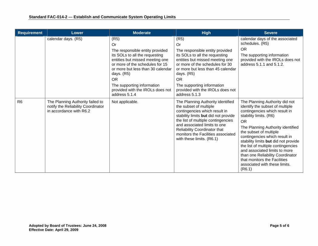
Standard FAC-014-2 — Establish and Communicate System Operating Limits
Adopted by Board of Trustees: June 24, 2008 Page 5 of 6 Effective Date: April 29, 2009
Requirement Lower Moderate High Severe calendar days. (R5)
(R5)
Or
The responsible entity provided its SOLs to all the requesting entities but missed meeting one or more of the schedules for 15 or more but less than 30 calendar days. (R5)
OR
The supporting information provided with the IROLs does not address 5.1.4
(R5)
Or
The responsible entity provided its SOLs to all the requesting entities but missed meeting one or more of the schedules for 30 or more but less than 45 calendar days. (R5)
OR
The supporting information provided with the IROLs does not address 5.1.3
calendar days of the associated schedules. (R5)
OR
The supporting information provided with the IROLs does not address 5.1.1 and 5.1.2.
R6
The Planning Authority failed to notify the Reliability Coordinator in accordance with R6.2
Not applicable. The Planning Authority identified the subset of multiple contingencies which result in stability limits but did not provide the list of multiple contingencies and associated limits to one Reliability Coordinator that monitors the Facilities associated with these limits. (R6.1)
The Planning Authority did not identify the subset of multiple contingencies which result in stability limits. (R6)
OR
The Planning Authority identified the subset of multiple contingencies which result in stability limits but did not provide the list of multiple contingencies and associated limits to more than one Reliability Coordinator that monitors the Facilities associated with these limits. (R6.1)

Standard FAC-014-2 — Establish and Communicate System Operating Limits
Adopted by Board of Trustees: June 24, 2008 Page 6 of 6 Effective Date: April 29, 2009
E. Regional Differences None identified.
Version History
Version Date Action Change Tracking
1 November 1, 2006
Adopted by Board of Trustees New
2 Changed the effective date to January 1, 2009 Replaced Levels of Non-compliance with Violation Severity Levels
Revised
2 June 24, 2008 Adopted by Board of Trustees: FERC Order Revised
2 January 22, 2010
Updated effective date and footer to April 29, 2009 based on the March 20, 2009 FERC Order
Update

WECC Standard FAC-501-WECC-1 – Transmission Maintenance
Adopted by Board of Trustees: October 29, 2008 1
A. Introduction
1. Title: Transmission Maintenance
2. Number: FAC-501-WECC-1
3. Purpose: To ensure the Transmission Owner of a transmission path identified in the table titled “Major WECC Transfer Paths in the Bulk Electric System” including associated facilities has a Transmission Maintenance and Inspection Plan (TMIP); and performs and documents maintenance and inspection activities in accordance with the TMIP.
4. Applicability
4.1. Transmission Owners that maintain the transmission paths in the most current table titled “Major WECC Transfer Paths in the Bulk Electric System” provided at:
http://www.wecc.biz/Standards/Approved%20Standards/Supporting%20Tables/Table%20Major%20Paths%204-28-08.pdf
5. Effective Date: On the first day of the first quarter, after applicable regulatory approval.
B. Requirements
R.1. Transmission Owners shall have a TMIP detailing their inspection and maintenance requirements that apply to all transmission facilities necessary for System Operating Limits associated with each of the transmission paths identified in table titled “Major WECC Transfer Paths in the Bulk Electric System.” [Violation Risk Factor: Medium] [Time Horizon: Long-term Planning]
R1.1. Transmission Owners shall annually review their TMIP and update as required. [Violation Risk Factor: Medium] [Time Horizon: Long-term Planning]
R.2. Transmission Owners shall include the maintenance categories in Attachment 1-FAC-501-WECC-1 when developing their TMIP. [Violation Risk Factor: Medium] [Time Horizon: Operations Assessment]
R.3. Transmission Owners shall implement and follow their TMIP. [Violation Risk Factor: Medium] [Time Horizon: Operations Assessment]
C. Measures
M1. Transmission Owners shall have a documented TMIP per R.1.
M1.1 Transmission Owners shall have evidence they have annually reviewed their TMIP and updated as needed.
M2. Transmission Owners shall have evidence that their TMIP addresses the required maintenance details of R.2.
M3. Transmission Owners shall have records that they implemented and followed their TMIP as required in R.3. The records shall include:
1. The person or crew responsible for performing the work or inspection,
2. The date(s) the work or inspection was performed,
3. The transmission facility on which the work was performed, and

WECC Standard FAC-501-WECC-1 – Transmission Maintenance
Adopted by Board of Trustees: October 29, 2008 2
4. A description of the inspection or maintenance performed.
D. Compliance
1. Compliance Monitoring Process
1.1 Compliance Monitoring Responsibility Compliance Enforcement Authority
1.2 Compliance Monitoring Period The Compliance Enforcement Authority may use one or more of the following methods to assess compliance:
- Self-certification conducted annually
- Spot check audits conducted anytime with 30 days notice given to prepare
- Periodic audit as scheduled by the Compliance Enforcement Authority
- Investigations
- Other methods as provided for in the Compliance Monitoring Enforcement Program
The Reset Time Frame shall be one year.
1.3 Data Retention
The Transmission Owners shall keep evidence for Measure M1 through M3 for three years plus the current year, or since the last audit, whichever is longer.
1.4 Additional Compliance Information
No additional compliance information.
2. Violation Severity Levels
2.1. Lower: There shall be a Lower Level of non-compliance if any of the following conditions exist:
2.1.1 The TMIP does not include associated Facilities for one of the Paths identified in Attachment 1 FAC-501-WECC-1 as required by R.1 but Transmission Owners are performing maintenance and inspection for the missing Facilities.
2.1.2 Transmission Owners did not review their TMIP annually as required by R.1.1.
2.1.3 The TMIP does not include one maintenance category identified in Attachment 1 FAC-501-WECC-1 as required by R.2 but Transmission Owners are performing maintenance and inspection for the missing maintenance categories.
2.1.4 Transmission Owners do not have maintenance and inspection records as required by R.3 but have evidence that they are implementing and following their TMIP.
2.2. Moderate: There shall be a Moderate Level of non-compliance if any of the following conditions exist:
2.2.1 The TMIP does not include associated Facilities for two of the Paths identified in the most current Table titled “Major WECC Transfer Paths in the Bulk Electric System” as required by R.1 and Transmission Owners are not performing maintenance and inspection for the missing Facilities.
2.2.2 The TMIP does not include two maintenance categories identified in Attachment 1 FAC-501-WECC-1 as required by R.2 but Transmission Owners are performing

WECC Standard FAC-501-WECC-1 – Transmission Maintenance
Adopted by Board of Trustees: October 29, 2008 3
maintenance and inspection for the missing maintenance categories.
2.2.3 Transmission Owners are not performing maintenance and inspection for one maintenance category identified in Attachment 1 FAC-501-WECC-1 as required in R3.
2.3. High: There shall be a High Level of non-compliance if any of the following condition exists:
2.3.1 The TMIP does not include associated Facilities for three of the Paths identified in the most current Table titled “Major WECC Transfer Paths in the Bulk Electric System” as required by R.1 and Transmission Owners are not performing maintenance and inspection for the missing Facilities.
2.3.2 The TMIP does not include three maintenance categories identified in Attachment 1 FAC-501-WECC-1 as required by R.2 but Transmission Owners are performing maintenance and inspection for the missing maintenance categories.
2.3.3 Transmission Owners are not performing maintenance and inspection for two maintenance categories identified in Attachment 1 FAC-501-WECC-1 as required in R3.
2.4. Severe: There shall be a Severe Level of non-compliance if any of the following condition exists:
2.4.1 The TMIP does not include associated Facilities for more than three of the Paths identified in the most current Table titled “Major WECC Transfer Paths in the Bulk Electric System” as required by R.1 and Transmission Owners are not performing maintenance and inspection for the missing Facilities.
2.4.2 The TMIP does not exist or does not include more than three maintenance categories identified in Attachment 1 FAC-501-WECC-1 as required by R.2 but Transmission Owners are performing maintenance and inspection for the missing maintenance categories.
2.4.3 Transmission Owners are not performing maintenance and inspection for more than two maintenance categories identified in Attachment 1 FAC-501-WECC-1 as required in R3.
Version History – Shows Approval History and Summary of Changes in the Action Field
Version Date Action Change Tracking
1 April 16, 2008 Permanent Replacement Standard for PRC-STD-005-1
1 April 21, 2011 FERC Order issued approving FAC-501-WECC-1 (approval effective June 27, 2011)

WECC Standard FAC-501-WECC-1 – Transmission Maintenance
Adopted by Board of Trustees: October 29, 2008 4
Attachment 1-FAC-501-WECC-1
Transmission Line and Station Maintenance Details
The maintenance practices in the TMIP may be performance-based, time-based, conditional based, or a combination of all three. The TMIP shall include:
1. A list of Facilities and associated Elements necessary to maintain the SOL for the transfer paths identified in the most current Table titled “Major WECC Transfer Paths in the Bulk Electric System;”
2. The scheduled interval for any time-based maintenance activities and/or a description supporting condition or performance-based maintenance activities including a description of the condition based trigger;
3. Transmission Line Maintenance Details:
a. Patrol/Inspection
b. Contamination Control
c. Tower and wood pole structure management
4. Station Maintenance Details:
a. Inspections
b. Contamination Control
c. Equipment Maintenance for the following:
• Circuit Breakers
• Power Transformers (including phase-shifting transformers)
• Regulators
• Reactive Devices (including, but not limited to, Shunt Capacitors, Series
Capacitors, Synchronous Condensers, Shunt Reactors, and Tertiary
Reactors)

Updated: June 12, 2013
Page 1 of 3
FAC Five-Year Review Action Plan
Effort Task Description Lead Organization Deliverables Estimated Completion
Inte
rnal
Sta
ndar
ds P
roce
ss P
repa
ratio
n
Brief the Standards Committee
Informally discuss the work plan for this project with the SC
Standards SC Talking Points document Five-Year Review Template Standards Announcement
Complete
Issue Standards Announcement
Invite industry SMEs to serve on the Five-Year Review Team
Standards Standards Announcement Complete
Propose FYRT members
Review FYRT nominations and recommend FYRT members to the SC
Standards FYRT Roster recommendation for SC Complete
Finalize FYRT Obtain SC approval of Review Team members
Standards Committee Review Team Approval Complete
Advise FYRT members Advise FYRT members and leadership of status, date range of initial FYRT conference call and face-to-face meeting, and provide documents
Standards Email to FYRT members (include Doodle for tentative event scheduling) Five-Year Review Template Project Action Plan
Complete
Internal conference call to discuss five-year review
Finalize recommendations on directives, RBS, and P81
Standards (Mallory, Edd, Sean)
Complete Staff Section of Five-Year Review Template
Complete
Five
-Yea
r Re
view
Pr
epar
atio
n
Review FYR template and make tentative recommendations
Develop plan for NERC review of directives, RBS, and P81
Standards (Mallory) Five-Year Review Template Complete

Updated: June 12, 2013
Page 2 of 3
Effort Task Description Lead Organization Deliverables Estimated Completion
Industry Training webinar
Train industry and FYRT on the five-year review process, particularly as it pertains to this project
Standards Five-Year Review PowerPoint Five-Year Review Template
Complete
Initial FYRT conference call
Review Team introductions, confirm receipt of documents, discuss Action Plan, discuss initial NERC recommendations, schedule first face-to-face meeting
Review Team Meeting Notes
Complete
Form
al F
ive-
Year
Rev
iew
FYRT Meeting First Five-Year Review Team meeting to develop Draft Five-Year-Review Recommendation
Review Team Meeting Notes Draft Five-Year Review Recommendation
June 17-19, 2013
Review Team conference call (if necessary)
Further develop Draft Five-Year-Review Recommendation
Review Team Revise draft Five-Year Review Recommendation and supporting documents, as needed
June 25, 2013
Review Team conference call
Finalize posting for comment
Review Team Finalize Five-Year Review Recommendation and supporting documents, as needed
June/July 2013
Post recommendation Recommend whether the Reliability Standard should be reaffirmed, revised, or withdrawn
Standards Five-Year Review Recommendation TBD – 45-day comment period ideally beginning in July
Webinar Advise industry of Review Team recommendation
Review Team Chair/Standards
Final Five-Year Review Recommendation PowerPoint
TBD – during posting period
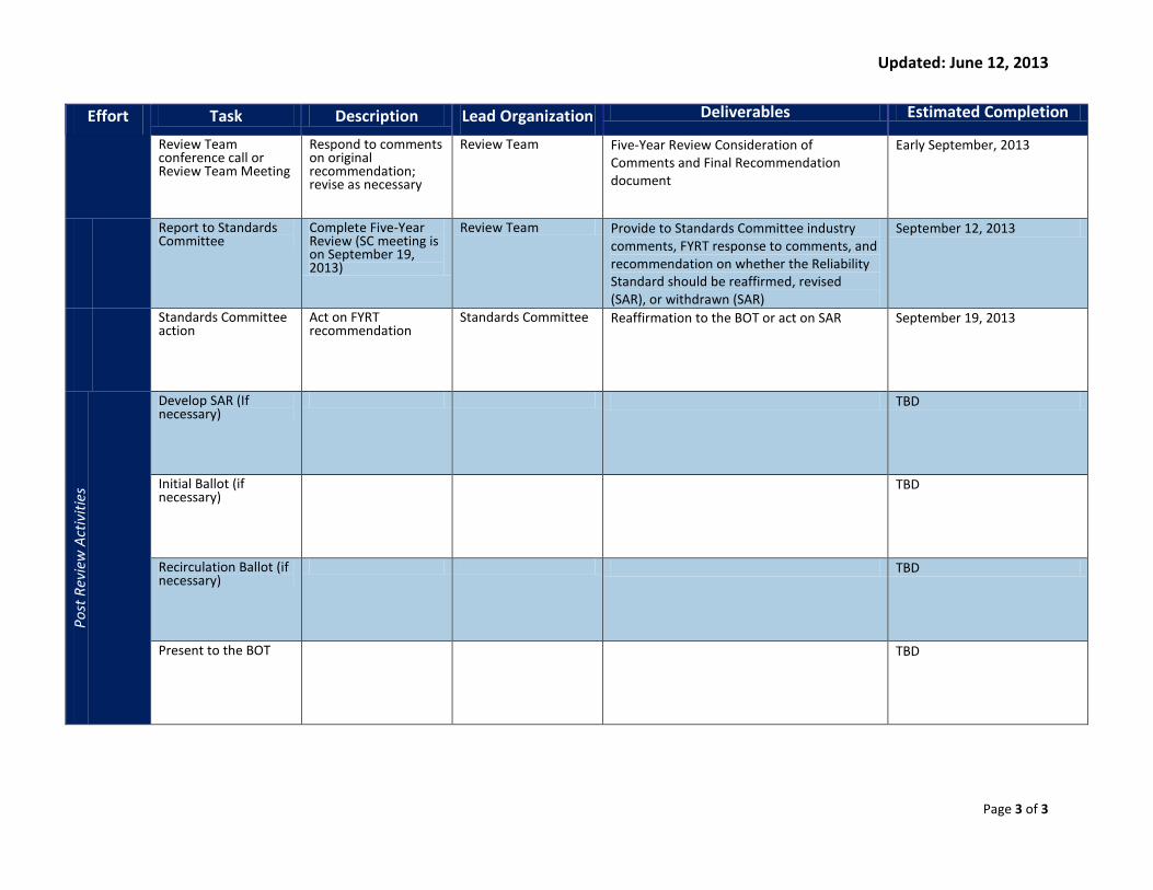
Updated: June 12, 2013
Page 3 of 3
Effort Task Description Lead Organization Deliverables Estimated Completion
Review Team conference call or Review Team Meeting
Respond to comments on original recommendation; revise as necessary
Review Team Five-Year Review Consideration of Comments and Final Recommendation document
Early September, 2013
Report to Standards Committee
Complete Five-Year Review (SC meeting is on September 19, 2013)
Review Team Provide to Standards Committee industry comments, FYRT response to comments, and recommendation on whether the Reliability Standard should be reaffirmed, revised (SAR), or withdrawn (SAR)
September 12, 2013
Standards Committee action
Act on FYRT recommendation
Standards Committee Reaffirmation to the BOT or act on SAR September 19, 2013
Post
Rev
iew
Act
iviti
es
Develop SAR (If necessary)
TBD
Initial Ballot (if necessary)
TBD
Recirculation Ballot (if necessary)
TBD
Present to the BOT TBD

Team Roster FAC Five-Year Review Team
Participant Entity
Chair John Beck Con Edison
Vice Chair Michael Steckelberg Great River Energy
Member Brian Dale Georgia Power Company
Member Ruth Kloecker ITC Holdings
Member Stewart Rake Luminant Generation Company LLC
Memebr Ganesh Velummylum Northern Indiana Public Service Co.
NERC Staff Mallory Huggins (Lead Standards Developer) NERC
NERC Staff Sean Cavote (Supporting Standards Developer) NERC
NERC Staff Ed Dobrowolski (Supporting Standards Developer) NERC
NERC Staff Laura Hussey (Director of Standards Development)
NERC
Version Date Description
1.0 5/13/2013 Initial posting
2.0 5/21/2013 Updated to add new member

Conference Call Notes Five-Year Review of FAC Standards June 10, 2013 | 1-5 p.m. Eastern Administrative
1. Introductions
Standards Developer Mallory Huggins initiated the meeting and reviewed the NERC Antitrust Compliance Guidelines, Public Announcement, Participant Conduct Policy, and Email List Policy. She thanked all members and observers for participating in the call and led group introductions. The following members and observers were in attendance:
Name Company Member/Observer
John Beck (Chair) Consolidated Edison of New York M
Mike Steckelberg (Vice Chair) Great River Energy M
Brian Dale Georgia Power Company M
Ruth Kloecker ITC Holdings M
Stewart Rake Luminant Generation Company M
Ganesh Velummylum Northern Indiana Public Service Co. M
Kenneth Goldsmith Alliant Energy O
Vic Howell WECC O
Lisa Martin Austin Energy O
Jason Snodgrass Georgia Transmission Corporation O
Todd VanCleave Sunflower Electric O
Kumar Agarwal FERC O
Mallory Huggins NERC M
Sean Cavote NERC M

Five-Year Review of FAC Standards Conference Call Notes 2
2. Review Meeting Agenda and Objectives
Mallory reviewed the agenda and objectives. She indicated that her goals for the conference call were to allow team members to meet, to review the five-year review process and answer questions about it, and to begin to review the FAC family of standards.
Agenda Items
1. Review Five-Year Review Team Roster
a. Mallory noted that Ganesh Velummylum was selected to replace Robert DeMelo on the drafting team and reminded the team that John Beck is serving as chair, with Mike Steckelberg supporting him as vice chair. She requested that team members review the roster and send her any title, company, or contact information corrections.
2. Overview of Five-Year Review Process, Template, and Action Plan
a. Overview of Five-Year Review Process: FAC Five-Year Review Team (FYRT) members indicated that almost all of them had already seen the five-year review process webinar from May 8. Mallory reviewed the process to ensure that all members and observers had the same understanding, and to allow the opportunity for questions about the process. She reminded the FAC FYRT that NERC is obligated, under its Standard Processes Manual, to conduct reviews of standards that have not been substantially revised in five years. While only a few FAC standards technically fit that description, the team will be looking at the full body of standards to identify opportunities for consolidation. In about four months, the team should have produced a recommendation (which will be reviewed by the Standards Committee and then NERC’s Board of Trustees) that each of the FAC standards be affirmed, revised, or retired. Mallory also reminded the FAC FYRT about the team listservs and project page, where meeting agendas and notes will be posted.
b. Five-Year Review Template: Mallory reviewed the content of the five-year review template, which requires the team to consider clarity, definitions, compliance elements, consistency with other standards, changes in technology, system conditions, or other factors, and whether generator interconnection Facilities are appropriately accounted for. Ultimately, these documents will be what the team posts, though they may be consolidated in some fashion. The template will help ensure that the FAC FYRT is providing the appropriate justification for advocating for its position with stakeholders.
c. Five-Year Review Action Plan: Mallory reviewed the FAC FYRT action plan. Following its June meetings, the next major milestone for the team will be posting its recommendations for a 45-day comment period, ideally in late July. After that comment period, likely in early September, the team will review all comments and prepare a summary response indicating how it incorporated the comments. If the team did not incorporate some comments, it should explain why.
Five-Year Review of FAC Standards Conference Call Notes 3
3. Review of Individual Standards, History, and Associated issues
a. Mallory reviewed a tracking document that incorporates key dates in each standard’s revision history, Paragraph 81 Phase 1 stakeholder comments, FERC directives, interpretations, CANs, and other notes on compliance and enforcement.
4. Plan for Review of Requirements for Possible Consolidation
a. Mallory indicated that, along with the review of individual standards and requirements, the team should consider the FAC standards from a high level and think about whether some requirements might be redundant, or whether some standards might logically be combined.
5. Objectives for In-Person Meeting
a. Mallory asked that by the in-person meeting June 17-19 in DC, all team members review the standards tracking document, along with all standards and requirements (in an attempt to identify opportunities for consolidation. The goal of the meeting is to leave DC with at least tentative recommendations to affirm, revise, or retire each standard, including identification of opportunities for consolidation and a plan for posting and soliciting informal feedback on recommendations and supporting documents.
6. Informal Outreach
a. Mallory asked FAC FYRT members to start considering opportunities for industry outreach. She encouraged members to get feedback within their entities, and to think about industry groups that might be worth reaching out to for specific feedback.
7. Future Meeting Dates
a. June 17-19, 2013, NERC’s Offices in Washington, DC
b. June 25, 2013, 9 a.m.-noon, Conference Call
8. Adjourn
a. The meeting was adjourned at 2:00 p.m. Eastern.