FAC-37B (SHIBAURA) FAC-37BC (SHIBAURA) FAC-16B …€¦ · FAC-28BC (SHIBAURA) FAC-52B (NISSAN)...
102
FAC-37B (SHIBAURA) FAC-37BC (SHIBAURA) FAC-16B (SHIBAURA) FAC-21B (SHIBAURA) FAC-21BC (SHIBAURA) FAC-28B (SHIBAURA) FAC-28BC (SHIBAURA) FAC-52B (NISSAN) FAC-52BC (NISSAN)
Transcript of FAC-37B (SHIBAURA) FAC-37BC (SHIBAURA) FAC-16B …€¦ · FAC-28BC (SHIBAURA) FAC-52B (NISSAN)...

FAC-37B (SHIBAURA)FAC-37BC (SHIBAURA)
FAC-16B (SHIBAURA)FAC-21B (SHIBAURA)FAC-21BC (SHIBAURA)FAC-28B (SHIBAURA)FAC-28BC (SHIBAURA)FAC-52B (NISSAN)FAC-52BC (NISSAN)

Preface
This service manual explains about the cautions for maintenance jobs and is to serve a guide for the electric system, and troubleshooting for service personnel. In this book the fundamental matters and other things already mentioned in the “Instruction Manual” and the “Parts Catalogue” are omitted to avoid duplication. Therefore, for the operation and handling of this unit, we request you to refer to the instruction manual and caution plates, and further for the structure and components of the unit, please refer to the “Parts Catalogue” separately to be supplied with the unit. If you should find any description which does not coincide with the instruction manual and parts catalog, we request you to make sure to start the job after clarifying it. Service personnel is required to safely take quick and proper countermeasures as well as to use correct technology of maintenance in case of field services and periodical maintenance. It is important that service personnel should have proper and sufficient knowledge about the structure and function of the unit and should be well familiar with such technique mentioned in them. Regarding the part numbers mentioned in this manual, we request you to refer to the Parts catalogue separately supplied together with the unit, because the parts numbers in this manual are sometimes changed.
Copies of this service manual are intended to be distributed to limited numbersof our customers. The unauthorized reproduction or distribution of this servicemanual is prohibited.

Table of Contents
1. Specification -------------------------------------------------------------------------------------------- 1-1 1.1 Specifications ----------------------------------------------------------------------------------------------------------------- 1-1 1.2 Set Value ----------------------------------------------------------------------------------------------------------------------- 1-6 1.3 Outline drawing -------------------------------------------------------------------------------------------------------------- 1-11 1.4 Internal Components and Part Names ------------------------------------------------------------------------------ 1-12 1.5 Instrument panel ------------------------------------------------------------------------------------------------------------- 1-19 1.6 Piping Diagram ----------------------------------------------------------------------------------------------------------------- 1-21 1.7 Fuel piping ----------------------------------------------------------------------------------------------------------------------- 1-30 2. Maintenance --------------------------------------------------------------------------------------------- 2-1 2.1 Cautions for Overhauling ------------------------------------------------------------------------------------------------- 2-1 2.2 Tightening torque ----------------------------------------------------------------------------------------------------------- 2-2 2.3 How to adjust regulator and how to replace diaphragm ----------------------------------------------------- 2-3 2.4 Replacement of unloader spare parts ------------------------------------------------------------------------------- 2-6 2.5 Pressure adjustment procedure of pressure control valve and replacement of spare parts --- 2-8 2.6 Inspection/replacement of auto relief valve spare parts ----------------------------------------------------- 2-9 2.7 Change Oil Separator ----------------------------------------------------------------------------------------------------- 2-9 2.8 Change of pellet assembly of by-pass valve --------------------------------------------------------------------- 2-11 2.9 Clean inside of Fuel Tank ----------------------------------------------------------------------------------------------- 2-12 2.10 Values of Various Adjustments of Engine ------------------------------------------------------------------------- 2-13 3. Electric System --------------------------------------------------------------------------------------- 3-1 3.1 Engine electric appliances ---------------------------------------------------------------------------------------------- 3-1 4. Troubleshooting --------------------------------------------------------------------------------------- 4-1 4.1 Repairing Procedures ------------------------------------------------------------------------------------------------------- 4-1 4.2 Failures of compressor and engine ---------------------------------------------------------------------------------- 4-3 4.3 Operation of emergency switch ---------------------------------------------------------------------------------------- 4-9 4.4 Others --------------------------------------------------------------------------------------------------------------------------- 4-12 4.5 Explanation of trouble diagnosis -------------------------------------------------------------------------------------- 4-13 5. References ----------------------------------------------------------------------------------------------- 5-1 5.1 Comparison between consumable parts and electrical appliances -------------------------------------- 5-1 5.2 Engine Wiring Diagram --------------------------------------------------------------------------------------------------- 5-5
1. Specification
1-1
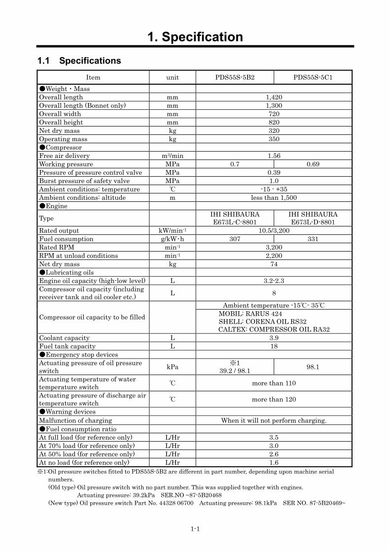
1.1 Specifications Item unit PDS55S-5B2 PDS55S-5C1
Weight・Mass Overall length mm 1,420 Overall length (Bonnet only) mm 1,300 Overall width mm 720 Overall height mm 820 Net dry mass kg 320 Operating mass kg 350 Compressor Free air delivery m3/min 1.56 Working pressure MPa 0.7 0.69 Pressure of pressure control valve MPa 0.39 Burst pressure of safety valve MPa 1.0 Ambient conditions: temperature -15 - +35 Ambient conditions: altitude m less than 1,500 Engine Type IHI SHIBAURA
E673L-C-8801 IHI SHIBAURA E673L-D-8801
Rated output kW/min-1 10.5/3,200 Fuel consumption g/kW・h 307 331 Rated RPM min-1 3,200 RPM at unload conditions min-1 2,200 Net dry mass kg 74 Lubricating oils Engine oil capacity (high-low level) L 3.2-2.3 Compressor oil capacity (including receiver tank and oil cooler etc.) L 8
Ambient temperature -15- 35 Compressor oil capacity to be filled MOBIL: RARUS 424
SHELL: CORENA OIL RS32 CALTEX: COMPRESSOR OIL RA32
Coolant capacity L 3.9 Fuel tank capacity L 18 Emergency stop devices Actuating pressure of oil pressure switch kPa ※1
39.2 / 98.1 98.1 Actuating temperature of water temperature switch more than 110 Actuating pressure of discharge air temperature switch more than 120 Warning devices Malfunction of charging When it will not perform charging. Fuel consumption ratio At full load (for reference only) L/Hr 3.5 At 70% load (for reference only) L/Hr 3.0 At 50% load (for reference only) L/Hr 2.6 At no load (for reference only) L/Hr 1.6 ※1:Oil pressure switches fitted to PDS55S-5B2 are different in part number, depending upon machine serial
numbers. (Old type) Oil pressure switch with no part number. This was supplied together with engines.
Actuating pressure: 39.2kPa SER.NO ~87-5B20468 (New type) Oil pressure switch Part No. 44328 06700 Actuating pressure: 98.1kPa SER NO. 87-5B20469~

1. Specification
1-2
Item unit PDS75S[SC]-5B2 PDS75S[SC]-5C1 Weight・Mass Overall length mm 1,580 Overall length (Bonnet only) mm 1,460 Overall width mm 750 Overall height mm 865 Net dry mass kg 425 [435] Operating mass kg 465 [475] Compressor Free air delivery m3/min 2.1 Working pressure MPa 0.7 0.69 Pressure of pressure control valve MPa 0.5 Burst pressure of safety valve MPa 1.0 Ambient conditions: temperature -15 - +35 Ambient conditions: altitude m less than 1,500 Engine Type IHI SHIBAURA
S753-C-8801 IHI SHIBAURA
S753-D-8801 Rated output kW/min-1 15.2/3,500 Fuel consumption g/kW・h 324 Rated RPM min-1 3,500 RPM at unload conditions min-1 2,000 Net dry mass kg 94 Lubricating oils Engine oil capacity (high-low level) L 4.5-2.2 Compressor oil capacity (including receiver tank and oil cooler etc.) L 11
Ambient temperature -15- 35 Compressor oil capacity to be filled MOBIL: RARUS 424
SHELL: CORENA OIL RS32 CALTEX: COMPRESSOR OIL RA32
Coolant capacity L 4.3 Fuel tank capacity L 28 Emergency stop devices Actuating pressure of oil pressure switch kPa ※1 39.2 / 98.1 98.1 Actuating temperature of water temperature switch more than 110 Actuating pressure of discharge air temperature switch more than 120 Warning devices Malfunction of charging When it will not perform charging. Fuel consumption ratio At full load (for reference only) L/Hr 5.0 At 70% load (for reference only) L/Hr 4.0 At 50% load (for reference only) L/Hr 3.2 At no load (for reference only) L/Hr 2.3 ※1:Oil pressure switches fitted to PDS75S[SC]-5B2 are different in part number, depending upon machine serial
numbers. (Old type) Oil pressure switch with no part number. This was supplied together with engines.
Actuating pressure: 39.2kPa SER.NO ~C6-5B20837 (New type) Oil pressure switch Part No. 44328 06700 Actuating pressure: 98.1kPa SER NO. C6-5B20838~

1. Specification
1-3
Item unit PDS100S [SC]-5B2 PDS100S [SC]-5C1 Weight・Mass Overall length mm 1,580 Overall length (Bonnet only) mm 1,460 Overall width mm 750 Overall height mm 865 Net dry mass kg 435 [445] Operating mass kg 475 [485] Compressor Free air delivery m3/min 2.8 Working pressure MPa 0.7 0.69 Pressure of pressure control valve MPa 0.5 Burst pressure of safety valve MPa 1.0 Ambient conditions: temperature -15 - +35 Ambient conditions: altitude m less than 1,500 Engine Type IHI SHIBAURA
S773L-C-8801 IHI SHIBAURA S773L-D-8801
Rated output kW/min-1 19/3,500 Fuel consumption g/kW・h 321 Rated RPM min-1 3,500 RPM at unload conditions min-1 2,000 Net dry mass kg 98 Lubricating oils Engine oil capacity (high-low level) L 4.9-2.7 Compressor oil capacity (including receiver tank and oil cooler etc.) L 11
Ambient temperature -15- 35 Compressor oil capacity to be filled MOBIL: RARUS 424
SHELL: CORENA OIL RS32 CALTEX: COMPRESSOR OIL RA32
Coolant capacity L 4.5 Fuel tank capacity L 28 Emergency stop devices Actuating pressure of oil pressure switch kPa ※1 39.2 / 98.1 98.1 Actuating temperature of water temperature switch more than 110 Actuating pressure of discharge air temperature switch more than 120 Warning devices Malfunction of charging When it will not perform charging. Fuel consumption ratio At full load (for reference only) L/Hr 6.0 At 70% load (for reference only) L/Hr 4.4 At 50% load (for reference only) L/Hr 3.8 At no load (for reference only) L/Hr 2.5 ※1:Oil pressure switches fitted to PDS100S[SC]-5B2 are different in part number, depending upon machine serial numbers.
(Old type) Oil pressure switch with no part number. This was supplied together with engines. Actuating pressure: 39.2kPa SER.NO ~B6-5B22360
(New type) Oil pressure switch Part No. 44328 06700 Actuating pressure: 98.1kPa SER NO. B6-5B22361~

1. Specification
1-4
Item unit PDS130S[SC]-5B2 Weight・Mass Overall length mm 1,700 Overall length (Bonnet only) mm 1,580 Overall width mm 890 Overall height mm 1,060 Net dry mass kg 665 [680] Operating mass kg 745 [760] Compressor Free air delivery m3/min 3.7 Working pressure MPa 0.7 Pressure of pressure control valve MPa 0.4 Burst pressure of safety valve MPa 1.0 Ambient conditions: temperature -15 - +35 Ambient conditions: altitude m less than 1,500 Engine Type IHI SHIBAURA N843L-C-8801 Rated output kW/min-1 28/3,000 Fuel consumption g/kW・h 272 Rated RPM min-1 3,000 RPM at unload conditions min-1 1,600 Net dry mass kg 160 Lubricating oils Engine oil capacity (high-low level) L 6-3 Compressor oil capacity (including receiver tank and oil cooler etc.) L 14
Ambient temperature -15- 35 Compressor oil capacity to be filled MOBIL: RARUS 424
SHELL: CORENA OIL RS32 CALTEX: COMPRESSOR OIL RA32
Coolant capacity L 6.6 Fuel tank capacity L 70 Emergency stop devices Actuating pressure of oil pressure switch kPa ※1 39.2 / 98.1 Actuating temperature of water temperature switch more than 110 Actuating pressure of discharge air temperature switch more than 120 Warning devices Malfunction of charging When it will not perform charging. Fuel consumption ratio At full load (for reference only) L/Hr 8.0 At 70% load (for reference only) L/Hr 5.5 At 50% load (for reference only) L/Hr 4.5 At no load (for reference only) L/Hr 2.8 ※1:Oil pressure switches fitted to PDS130S[SC]-5B2 are different in part number, depending upon machine serial
numbers. (Old type) Oil pressure switch with no part number. This was supplied together with engines.
Actuating pressure: 39.2kPa SER.NO ~B3-5B21393 (New type) Oil pressure switch Part No. 44328 06700 Actuating pressure: 98.1kPa SER NO. B3-5B21394~

1. Specification
1-5
Item unit PDS175S [SC]-5B2 PDS175S [SC]-5C1 Weight・Mass Overall length mm 1,970 2,070 Overall length (Bonnet only) mm 1,850 1,950 Overall width mm 950 Overall height mm 1,060 Net dry mass kg 800 [830] 790 [810] Operating mass kg 900 [930] 900 [920] Compressor Free air delivery m3/min 5.0 Working pressure MPa 0.7 0.69 Pressure of pressure control valve MPa 0.5 0.4 Burst pressure of safety valve MPa 1.0 Ambient conditions: temperature -15 - +40 Ambient conditions: altitude m less than 1,500 Engine Type NISSAN DIESEL
2A-TD27 NISSAN DIESEL
TD27B-08(VE pump type) Rated output kW/min-1 38.0/2,600 36.0/2,300 Fuel consumption g/kW・h 286 284 Rated RPM min-1 2,600 2,500 RPM at unload conditions min-1 1,300 1,250 Net dry mass kg 240 225 Lubricating oils Engine oil capacity (high-low level) L 10.0-8.0 Compressor oil capacity (including receiver tank and oil cooler etc.) L 16 10
Ambient temperature -15- 35 Compressor oil capacity to be filled MOBIL: RARUS 424
SHELL: CORENA OIL RS32 CALTEX: COMPRESSOR OIL RA32
Coolant capacity L 8.5 9.5 Fuel tank capacity L 90 Emergency stop devices Actuating pressure of oil pressure switch kPa 60 Actuating temperature of water temperature switch more than 110 Actuating pressure of discharge air temperature switch more than 120
Increase of condensate in fuel filter ml ― Condensate volume :over 120-170
Warning devices Malfunction of charging When it will not perform charging. Fuel consumption ratio At full load (for reference only) L/Hr 10.0 At 70% load (for reference only) L/Hr 7.5 At 50% load (for reference only) L/Hr 6.0 At no load (for reference only) L/Hr 3.5

1. Specification
1-6
1.2 Set Value Item unit PDS55S-5B2 PDS55S-5C1
Safety devices Discharge air temperature 120 Engine oil pressure kPa ※1 39.2 / 98.1 98.1 Engine coolant temperature 110 Fuel residual level L less than about 4 Set value Pressure control valve MPa 0.39 Actuating pressure of safety valve MPa 1.0
Unload starting pressure MPa 0.7 0.69 Engine RPM Rated RPM min-1 3,200 RPM at unload min-1 2,200 Indications of gauges or instruments during operation
Discharge pressure gauge (at full load)
MPa (kgf/cm2)
0.39-0.70 (4.0-7.1)
0.39-0.69 (4.0-7.0)
Discharge pressure gauge (at no load)
MPa (kgf/cm2)
0.70-0.90 (7.1-9.2)
0.69-0.90 (7.0-9.2)
※1:Oil pressure switches fitted to PDS55S-5B2 are different in part number, depending upon machine serial numbers. (Old type) Oil pressure switch with no part number. This was supplied together with engines.
Actuating pressure: 39.2kPa SER.NO ~87-5B20468 (New type) Oil pressure switch Part No. 44328 06700 Actuating pressure: 98.1kPa SER NO. 87-5B20469~

1. Specification
1-7
Item unit PDS75S[SC]-5B2 PDS75S[SC]-5C1
Safety devices Discharge air temperature 120 Engine oil pressure kPa ※1 39.2 / 98.1 98.1 Engine coolant temperature 110 Fuel residual level L less than about 6 Set value Pressure control valve MPa 0.5 Actuating pressure of safety valve MPa 1.0
Unload starting pressure MPa 0.7 0.69 Engine RPM Rated RPM min-1 3,500 RPM at unload min-1 2,000 Indications of gauges or instruments during operation
Discharge pressure gauge (at full load)
MPa (kgf/cm2)
0.50-0.70 (5.1-7.1)
0.50-0.69 (5.1-7.0)
Discharge pressure gauge (at no load)
MPa (kgf/cm2)
0.70-0.90 (7.1-9.2)
0.69-0.90 (7.0-9.2)
※1:Oil pressure switches fitted to PDS75S[SC]-5B2 are different in part number, depending upon machine serial numbers. (Old type) Oil pressure switch with no part number. This was supplied together with engines.
Actuating pressure: 39.2kPa SER.NO ~C6-5B20837 (New type) Oil pressure switch Part No. 44328 06700 Actuating pressure: 98.1kPa SER NO. C6-5B20838~
1. Specification
1-8
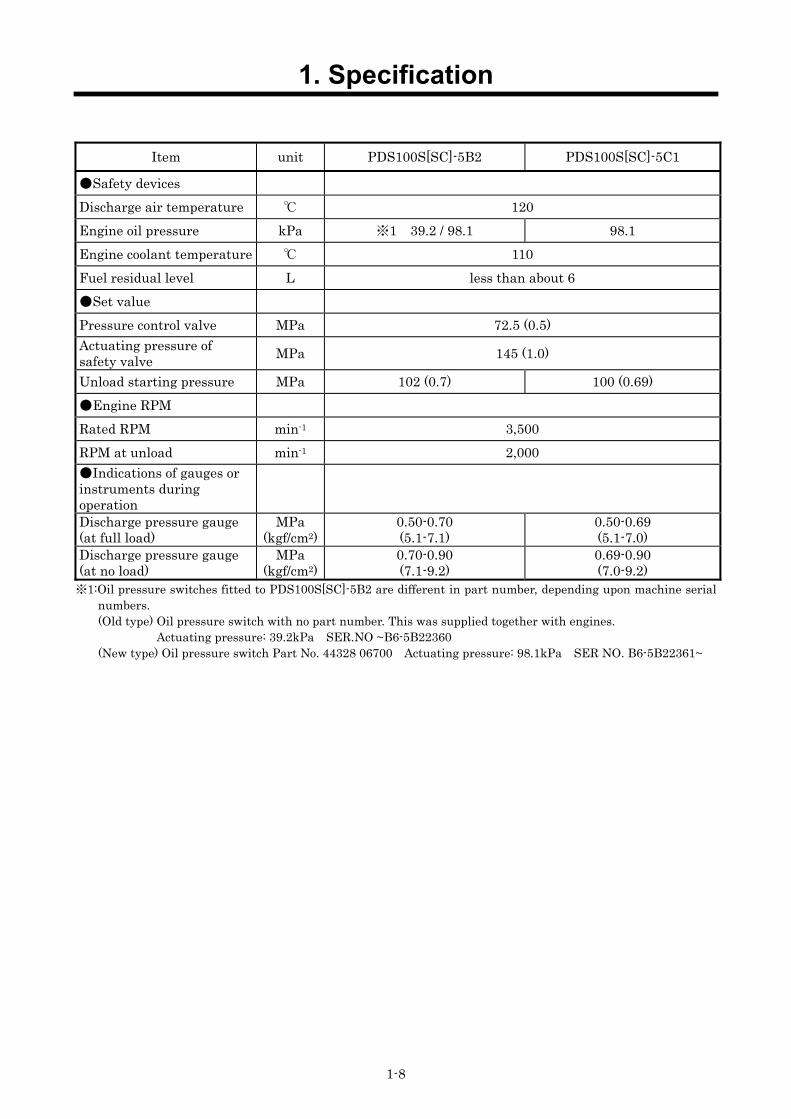
Item unit PDS100S[SC]-5B2 PDS100S[SC]-5C1
Safety devices Discharge air temperature 120 Engine oil pressure kPa ※1 39.2 / 98.1 98.1 Engine coolant temperature 110 Fuel residual level L less than about 6 Set value Pressure control valve MPa 72.5 (0.5) Actuating pressure of safety valve MPa 145 (1.0)
Unload starting pressure MPa 102 (0.7) 100 (0.69) Engine RPM Rated RPM min-1 3,500 RPM at unload min-1 2,000 Indications of gauges or instruments during operation
Discharge pressure gauge (at full load)
MPa (kgf/cm2)
0.50-0.70 (5.1-7.1)
0.50-0.69 (5.1-7.0)
Discharge pressure gauge (at no load)
MPa (kgf/cm2)
0.70-0.90 (7.1-9.2)
0.69-0.90 (7.0-9.2)
※1:Oil pressure switches fitted to PDS100S[SC]-5B2 are different in part number, depending upon machine serial numbers. (Old type) Oil pressure switch with no part number. This was supplied together with engines.
Actuating pressure: 39.2kPa SER.NO ~B6-5B22360 (New type) Oil pressure switch Part No. 44328 06700 Actuating pressure: 98.1kPa SER NO. B6-5B22361~
1. Specification
1-9
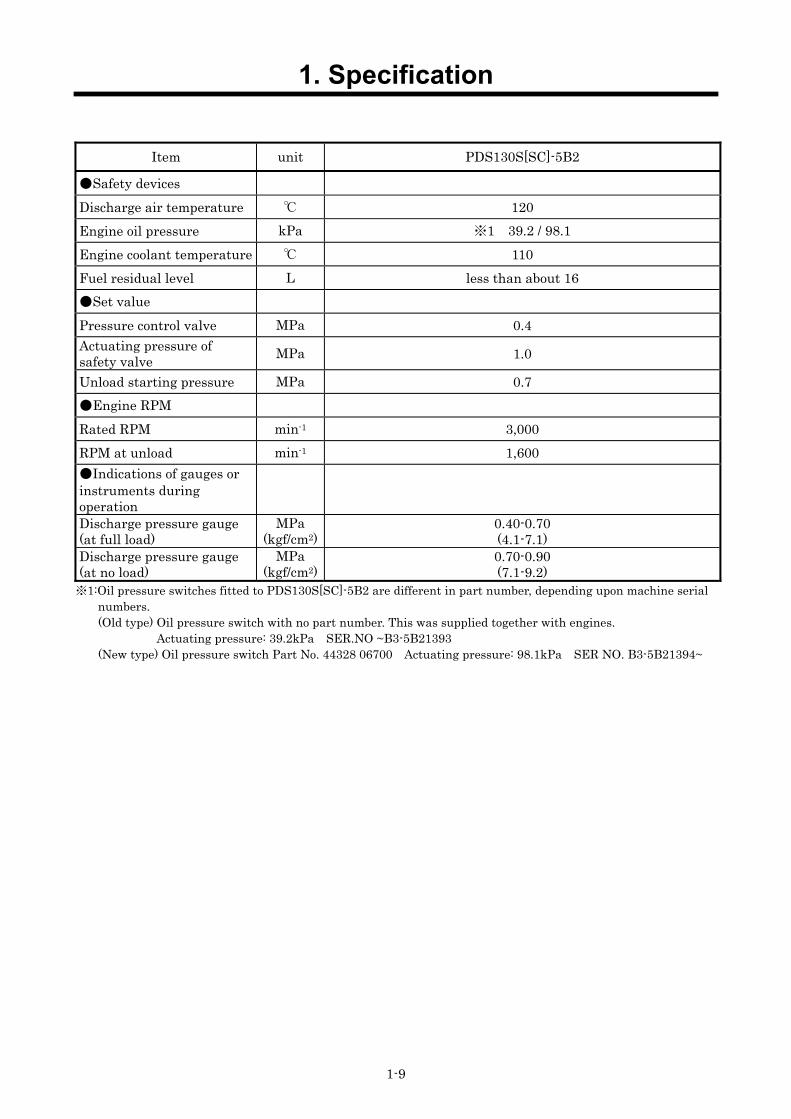
Item unit PDS130S[SC]-5B2
Safety devices Discharge air temperature 120 Engine oil pressure kPa ※1 39.2 / 98.1 Engine coolant temperature 110 Fuel residual level L less than about 16 Set value Pressure control valve MPa 0.4 Actuating pressure of safety valve MPa 1.0
Unload starting pressure MPa 0.7 Engine RPM Rated RPM min-1 3,000 RPM at unload min-1 1,600 Indications of gauges or instruments during operation
Discharge pressure gauge (at full load)
MPa (kgf/cm2)
0.40-0.70 (4.1-7.1)
Discharge pressure gauge (at no load)
MPa (kgf/cm2)
0.70-0.90 (7.1-9.2)
※1:Oil pressure switches fitted to PDS130S[SC]-5B2 are different in part number, depending upon machine serial numbers. (Old type) Oil pressure switch with no part number. This was supplied together with engines.
Actuating pressure: 39.2kPa SER.NO ~B3-5B21393 (New type) Oil pressure switch Part No. 44328 06700 Actuating pressure: 98.1kPa SER NO. B3-5B21394~

1. Specification
1-10
Item unit PDS175S[SC]-5B2 PDS175S[SC]-5C1
Safety devices Discharge air temperature 120 Engine oil pressure kPa 60 Engine coolant temperature 110 Increase of condensate in fuel filter ml ― Condensate volume
:over 120-170 Set value Pressure control valve MPa 0.5 0.4 Actuating pressure of safety valve MPa 1.0
Unload starting pressure MPa 0.7 0.69 Engine RPM Rated RPM min-1 2,600 2,500 RPM at unload min-1 1,300 1,250 Indications of gauges or instruments during operation
Discharge pressure gauge (at full load)
MPa (kgf/cm2)
0.50-0.70 (5.1-7.1)
0.40-0.69 (4.1-7.0)
Discharge pressure gauge (at no load)
MPa (kgf/cm2)
0.72-0.90 (7.3-9.2)

1. Specification
1-11
1.3 Outline drawing
PC08078
Item unit PDS55S
-5B2/5C1 PDS75S[SC]
-5B2/5C1 PDS100S[SC]
-5B2/5C1 PDS130S[SC]
-5B2 PDS175S[SC]
-5B2/5C1 Outline Overall length A mm 1,300 1,460 ← 1,580 1,850/1,950 Overall length A’ mm 1,420 1,580 ← 1,700 1,970/2,070 Overall width B mm 720 750 ← 890 950 Overall height C mm 820 865 ← 1,060 ← Door size Door D mm - 545 ← 600 690/745 Door E mm 515 585 ← 635 715/730 Door F mm - 565 ← 635 715/770 Door G mm 600 525 ← 600 690/775 Door H mm 1,320 1,900 ← 2,160 2,360/2,495 Door I mm - 2,170 ← 2,430 2,780/2,980 Door J mm 2,200 2,170 ← 2,450 2,780/2,980 Exhaust pipe diameter
K mm φ35 φ42.7 ← φ50.8 φ60.5
I
J
D
E
F
G
H
AA’B
C
K

1. Specification
1-12
1.4 Internal Components and Part Names
1.4.1 Standard Type (1) PDS55S-5B2/5C1
PDS55S-5C1
1 2 3 4 5 6 7 8 9 10 11 12 13 14 15 16
No. Description Function 1 Separator receiver tank For separating compressor oil from compressed air sent into the tank.
2 Safety valve For releasing compressed air to the atmosphere when the pressure rises higher than the rated pressure.
3 Pressure control valve For keeping receiver tank pressure above specified one constantly.
4 Auto relief valve For releasing the compressed air to the atmosphere. When the compressor stops.
5 Air filter For filtering the dust floating in the intake air. 6 Pressure regulator For regulating intake air volume. 7 Speed regulator For regulating compressor revolution speed. 8 Engine oil filler port For supplying and replenishing engine oil to engine. 9 Engine oil filter For filtering engine oil. 10 Engine For driving the compressor. 11 Fuel tank filler port For supplying and replenishing diesel fuel oil. 12 Sedimenter For separating water mixed or to be mixed in the fuel oil.
13 Fuel filter For filtering dust and foreign matter mixed or to be mixed in the fuel oil.
14 Air bleeding electromagnetic pump For feeding diesel fuel oil to engine.
15 Radiator For cooling the coolant for engine because it is water-cooled. 16 Oil cooler For cooling compressor oil circulating in the system.
A060073A

1. Specification
1-13
A060073BPDS55S-5C1
28 27 26 25 24 23 22 21 20 19 18 17
30
29
No. Description Function 17 Exhaust muffler For exhausting engine emission gas.
18 Reserve tank For checking engine cooling water level and for replenishing cooling water.
19 Oil cooler drain plug For draining compressor oil from oil cooler and also from oil lines. 20 Radiator drain plug For draining condensate accumulated at the bottom of radiator.
21 Fuel tank drain valve For draining condensate and water accumulated at the bottom of the fuel tank.
22 Fuel tank For storing diesel fuel oil. 23 Coolant drain valve For draining condensate from engine. 24 Engine oil level gauge For checking engine oil level. 25 Compressor oil filter For filtering compressor oil circulating in the system.
26 Compressor oil filler port For supplying and replenishing compressor oil.
27 Engine oil drain plug For draining engine oil for replacement of it and for maintenance.
28 Compressor oil drain valve For draining compressor oil from separator receiver tank.
29 Battery For electrically starting engine. 30 Air-end For compressing intake air.
※Instrument marked 29 is provided on the other side (opposite side of maintenance).

1. Specification
1-14
(2) PDS75,100S-5B2/5C1, PDS130S-5B2
A080604-1
PDS75S-5C1
1 2 3 4 5 6 7 8 9 10 11 12 13 14 15 16
No. Description Function 1 Separator receiver tank For separating compressor oil from compressed air sent into the tank. 2 Pressure regulator For regulating intake air volume.
3 Safety valve For releasing compressed air to the atmosphere when the pressure rises higher than the rated pressure.
4 Auto relief valve For releasing the compressed air to the atmosphere. When the compressor stops.
5 Air filter For filtering the dust floating in the intake air. 6 Speed regulator For regulating compressor revolution speed. 7 Engine oil filler port For supplying and replenishing engine oil to engine. 8 Engine oil filter For filtering engine oil. 9 Coolant drain plug For draining condensate from engine. 10 Engine For driving the compressor. 11 Fuel tank filler port For supplying and replenishing diesel fuel oil.
12 Filter for electromagnetic pump For filtering dust and foreign matter mixed or to be mixed in the fuel oil.
13 Air bleeding electromagnetic pump For feeding diesel fuel oil to engine.
14 Fuel filter (sedimenter built-in type)
For filtering dust and foreign things mixed in fuel oil and also for separating water.
15 Radiator For cooling the coolant for engine because it is water-cooled. 16 Oil cooler For cooling compressor oil circulating in the system.

1. Specification
1-15
A080605-1
PDS75S-5C1
27 26 25 24 23 22 21 20 19 18 17
30
29
28
No. Description Function 17 Exhaust muffler For exhausting engine emission gas. 18 Oil cooler drain plug For draining compressor oil from oil cooler and also from oil lines. 19 Engine oil drain plug For draining engine oil for replacement of it and for maintenance 20 Coolant drain plug For draining condensate from engine.
21 Reserve tank For checking engine cooling water level and for replenishing cooling water.
22 Engine oil level gauge For checking engine oil level. 23 Fuel tank For storing diesel fuel oil. 24 Compressor oil filter For filtering compressor oil circulating in the system.
25 Compressor oil filler port For supplying and replenishing compressor oil.
26 Fuel tank drain valve For draining condensate and water accumulated at the bottom of the fuel tank.
27 Compressor oil drain valve For draining compressor oil from separator receiver tank.
28 Battery For electrically starting engine. 29 Air-end For compressing intake air. 30 Pressure control orifice For keeping receiver tank pressure above specified one constantly.
※Instrument marked 28 is provided on the other side (opposite side of maintenance).

1. Specification
1-16
(3) PDS175S-5B2/5C1
A090272
PDS175S-5C1
No. Description Function 1 Oil separator For separating oil mist mixed in compressed air.
2 Safety valve For releasing compressed air to the atmosphere when the pressure rises higher than the rated pressure.
3 Pressure regulator For adjusting intake air volume (into compressor air-end) 4 Separator receiver tank For separating compressor oil from compressed air sent into the tank. 5 Air filter For filtering the dust floating in the intake air. 6 Speed regulator For regulating revolution speed of engine. 7 Engine oil level gauge For checking engine oil level. 8 Fuel tank For storing diesel fuel oil. 9 Fuel tank filler port For supplying and replenishing fuel oil. 10 Engine oil filler port For supplying and replenishing engine oil to engine.
11 Reserve tank For checking engine cooling water level and for replenishing cooling water.
12 Fuel filter (sedimenter built-in type)
For filtering dust and foreign matter mixed or to be mixed in the fuel oil and for separating water mixed or to be mixed in the fuel oil.
13 Radiator For cooling the coolant for engine because it is water-cooled. 14 Engine oil drain plug For draining engine oil for replacement of it and for maintenance 15 Radiator drain plug For draining condensate accumulated at the bottom of radiator. 16 Oil cooler drain valve For draining condensate accumulated at the bottom of oil cooler.
1 2 3 4 5 6 7 8 9 10 11 12 13
20 19 18 17 16 15 14

1. Specification
1-17
A090273PDS175S-5C1
No. Description Function
17 Fuel tank drain valve For draining condensate and water accumulated at the bottom of the fuel tank.
18 Compressor oil filler port For supplying and replenishing compressor oil. 19 Compressor oil drain valve For draining compressor oil from separator receiver tank. 20 Compressor oil level gauge For checking compressor oil level. 21 Oil cooler For cooling compressor oil circulating in the system. 22 Engine For driving the compressor. 23 Engine oil filter For filtering engine oil. 24 Coolant drain plug For draining condensate from engine. 25 Air-end For compressing intake air.
26 Pressure control valve For keeping the receiver tank pressure higher than 0.4MPa in the tank.
27 Battery For electrically starting engine. 28 Exhaust muffler Equipment which muffles an engine exhaust sound.
21 22 23 24 25 26
28 27

1. Specification
1-18
(4) PDS75,100SC-5B2/5C1, PDS130SC-5B2, PDS175SC-5B2/5C1 [Unit equipped with aftercooler] Only the special devise additionally or optionally attached to the standard unit are shown in the
following figure.
A090274
PDS175SC-5C1
5
1
2
3
4
5
No. Description Function 1 Drain separator For separating water from compressed air cooled through oil cooler. 2 After cooler For cooling compressed air.
3 Shutter for cold weather For shutting out atmospheric air from after-cooler to prevent after-cooler from getting frozen during cold season.
4 Drain warming valve For preventing freezing of water separated through drain separator when exhausting it.
5 Drain port of air pipe For collecting condensate and draining it.

1. Specification
1-19
1.5 Instrument panel (1)PDS55~130S
PDS55,75,100S-5C1
Turn the starter switch to “RUN” position. Then the lamp will go on.
Item Trouble Measures Monitor
Preheating
Press starter switch “RUN” and the lamp goes on and after preheating is finished, the lamp will be off.
―
When some little trouble occurs during operation, the lamp will go on. When the warning lamp goes on, take appropriate measures to recover the situation swiftly.
Item Trouble Measures Monitor
Fuel residual level
When fuel level of fuel tank becomes lower, the lamp goes on. Add fuel oil.
Charging Lamp goes on when alternator is not charging.
Check wiring. Check alternator.
The compressor stops when the emergency stop lamp goes on. Be sure to follow the measures shown below before starting the unit again.
Item Trouble Measures Monitor
Discharge air temperature
Lamp goes on when the air temperature at the outlet of the air-end reaches the set temperature of 120°C.
Engine oil pressure
Lamp goes on when engine oil pressure drops. The function pressure is below 98.1kPa.
Coolant temperature
Lamp goes on when coolant temperature reaches 110°C.
See 4.3 “Function of emergency switch”.
A080038E
1 2
3 4 5
Indicator lamp
Warning lamp
Emergency stop lamp
1. Discharge air pressure gauge 2. Fuel level gauge 3. Elapsed time indicator 4. Starter switch 5. Starting unloader valve
<Indicator lamp> 6. Preheating
<Warning lamp> 7. Fuel residual level 8. Charging
<Emergency stop lamp> 9. Discharge air temperature
10. Engine oil pressure 11. Coolant temperature
9 11 10 8 6 7
1. Specification
1-20
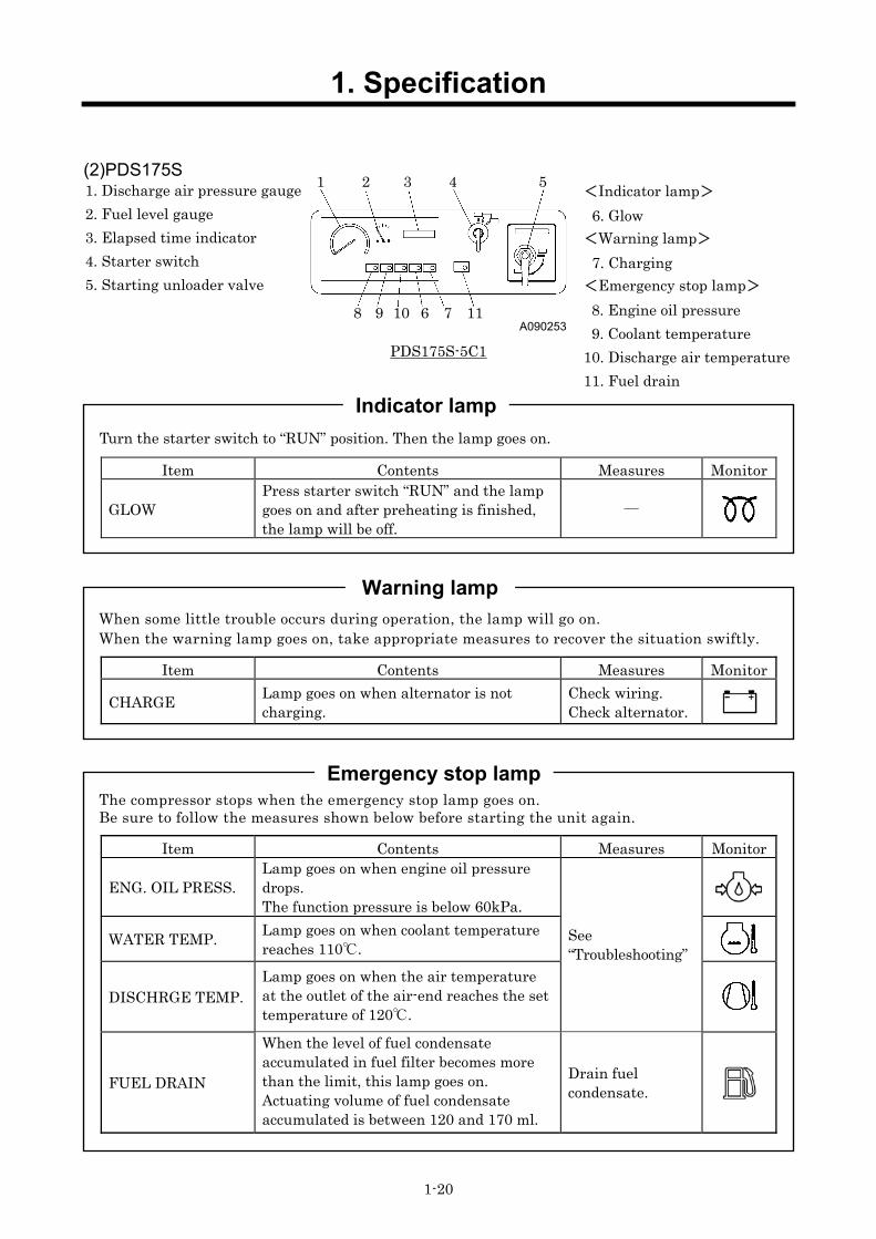
(2)PDS175S
A090253
PDS175S-5C1
Turn the starter switch to “RUN” position. Then the lamp goes on.
Item Contents Measures Monitor
GLOW Press starter switch “RUN” and the lamp goes on and after preheating is finished, the lamp will be off.
―
When some little trouble occurs during operation, the lamp will go on. When the warning lamp goes on, take appropriate measures to recover the situation swiftly.
Item Contents Measures Monitor
CHARGE Lamp goes on when alternator is not charging.
Check wiring. Check alternator.
The compressor stops when the emergency stop lamp goes on. Be sure to follow the measures shown below before starting the unit again.
Item Contents Measures Monitor
ENG. OIL PRESS. Lamp goes on when engine oil pressure drops. The function pressure is below 60kPa.
WATER TEMP. Lamp goes on when coolant temperature reaches 110.
DISCHRGE TEMP. Lamp goes on when the air temperature at the outlet of the air-end reaches the set temperature of 120.
See “Troubleshooting”
FUEL DRAIN
When the level of fuel condensate accumulated in fuel filter becomes more than the limit, this lamp goes on. Actuating volume of fuel condensate accumulated is between 120 and 170 ml.
Drain fuel condensate.
Indicator lamp
Warning lamp
Emergency stop lamp
1. Discharge air pressure gauge 2. Fuel level gauge 3. Elapsed time indicator 4. Starter switch 5. Starting unloader valve
<Indicator lamp> 6. Glow
<Warning lamp> 7. Charging
<Emergency stop lamp> 8. Engine oil pressure 9. Coolant temperature
10. Discharge air temperature 11. Fuel drain
1 2 3 4 5
8 9 10 6 7 11

1. Specification
1-21
1.6 Piping Diagram (1) PDS55S-5B2/5C1
A060044-2E

1. Specification
1-22
(2) PDS75S-5B2/5C1 PDS100S-5B2/5C1
A040623-2E

1. Specification
1-23
(3) PDS75SC-5B2/5C1 (Aftercooler Type) PDS100SC-5B2/5C1(Aftercooler Type)
A040624-2E
1. Specification
1-24
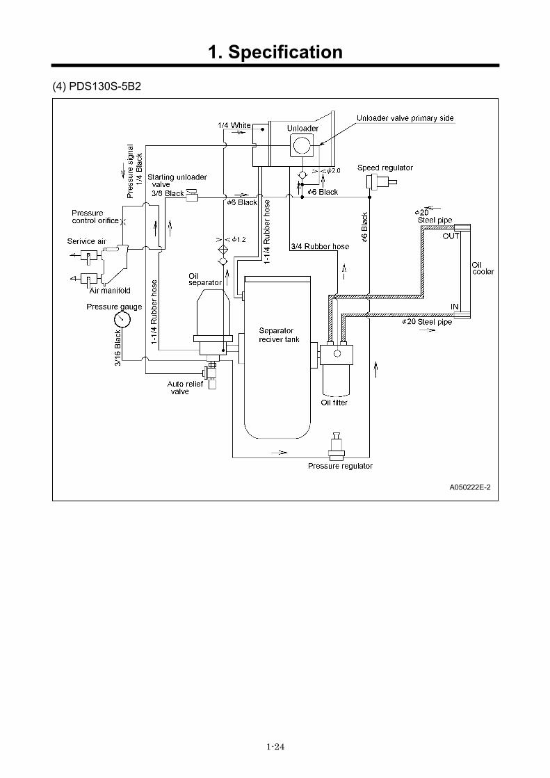
(4) PDS130S-5B2
A050222E-2

1. Specification
1-25
(5) PDS130SC-5B2 (Aftercooler Type)
A050223E-1
1. Specification
1-26
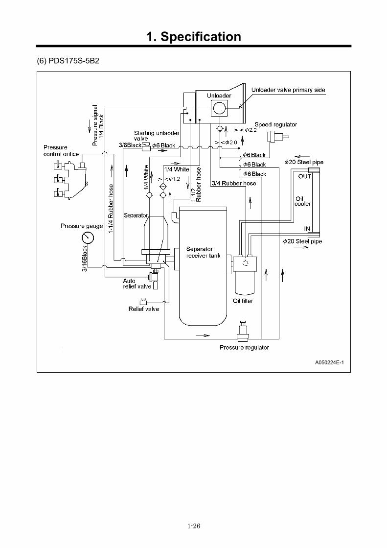
(6) PDS175S-5B2
A050224E-1

1. Specification
1-27
(7) PDS175SC-5B2 (Aftercooler Type)
A050225-2E

1. Specification
1-28
(8) PDS175S-5C1
A090251E

1. Specification
1-29
(9) PDS175SC-5C1 (Aftercooler Type)
A090252E-1

1. Specification
1-30
1.7 Fuel piping PDS55S-5B2/5C1
PC08080E PDS75,100S[SC]-5B2 PDS75S[SC]-5C1 :SER.NO.~C6-5C10155 PDS100S[SC]-5C1:SER.NO.~B6-5C10144 PD130S[SC]-5B2 :SER.NO.~B3-5B22153
PC08081E
PDS75S[SC]-5C1 :SER.NO.C6-5C10156~ PDS100S[SC]-5C1:SER.NO.B6-5C10145~ PD130S[SC]-5B2 :SER.NO.B3-5B22154~
PC08089E

1. Specification
1-31
PD175S[SC]-5B2
A070414E
PD175S[SC]-5C1
A090460E

2. Maintenance
2-1
2.1 Cautions for Overhauling 2.1.1 Precautions before starting work
(1) Work to be performed It is very important to always plan in advance what facilities, tools, instruments, materials, oil, etc. you will need to use; the exact locations and methods of performing inspection, adjustment, or disassembly; and the key points of any repair work to be performed.
(2) Care not to spill oil Use a pan to collect used compressor oil, engine oil when changing the oil or attaching or detaching an oil line. If a large volume of oil is expected to flow out make, sure to drain any accumulated oil from the reserve tank, engine oil pan in advance.
(3) Care when detaching parts When disassembling a complicated part, put a matching mark to indicate the position of detached parts for future reference. Make sure that the negative cable is detached from the battery terminals before starting repair work.
(4) Tools to be prepared ①Measuring instruments (e. g. tester, insulation resistance gauge etc.) ②Tools ③Torque wrenches ④Jigs and specialized tools ⑤Sealing tape ⑥Molybdenum sulfide (tube type) ⑦Lithium extreme pressure type grease (CALTEX MULTIFAK EP1) ⑧Diesel oil ⑨Compressor oil ⑩Cleaning cloths ⑪Literatures (such as manuals etc.)
2.1.2 Disassembly and assembly (1) Before removing nylon tubes, hydraulic/fuel hoses, it is necessary to clean the inside of machine
to prevent from entrance of dirt and foreign matters. (2) Perform disassembly work in a dust-free location whenever possible. (3) When disassembling parts, wash their outer surfaces and place them on a clean sheet of paper
or cloth, taking care not to contaminate or damage them. (4) Wash disassembled parts with diesel oil (cleaning solvent) after checking for contamination or
discoloration. However, do not wash rubber parts with diesel oil. (5) Be careful not to damage disassembled parts, they are precision built. (6) Replace consumables such as oil seals, O-rings, filters, oil, etc. with new items when
reassembling parts. (7) Install O-ring and oil seal which should be coated with clean lithium extreme pressure type
grease (CALTEX MULTIFAK EP1). (8) When reassembling parts, place each part in the order of assembly and take care that no parts
are missing or misassembled. (9) When reassembling an assembled part (set part), be sure to replace it as an assembly.
(10) Contamination or rusting may occur due to dust or humidity if parts are left in disassembled or partly disassembled condition for a long time. Therefore, be careful to prevent dust or rust from affecting parts if you have to leave the repair incomplete for a long period of time.
(11) Check tightening torque and clearance when assembling parts. (12) Check the direction of rotation, speed, and oil leakage after assembly. (13) Before starting the machine after disassembly, run it at low idle to check for unusual noises, etc.
to prevent engine or generator damage.

2. Maintenance
2-2
2.2 Tightening torque General bolts and nuts tightening torque
Fasten all the bolts and nuts with the specified tightening torque when assembling. Low or Middle carbon steel bolt
(SS400B etc…) High tensile strength bolt
(SCM435 etc…) 4.6~6.8(4T~6T)
Hexagon bolts
8.8~12.9(7T~12T)
Socket bolts Hexagon bolts
Hexagon bolts Width of across
flat (mm)
Tightening torque N・m (kgf・cm)
Socket bolts Width of across
flat (mm)
Hexagon bolts Width of across
flat (mm)
Tightening torque N・m (kgf・cm)
6 10 5 (51) 5 10 10 (100) 8 13 12 (124) 6 13 25 (245)
10 17 25 (245) 8 17 49 (485) 12 19 43 (425) 10 19 85 (845) 14 22 68 (675) 12 22 135 (1350) 16 24 106 (1055) 14 24 210 (2100) 18 27 145 (1450) 14 27 290 (2900) 20 30 205 (2050) 17 30 410 (4100) 22 32 280 (2800) 17 32 560 (5600) 24 36 345 (3450) 19 36 710 (7100)
Applied sections. For general sections such as bonnet and frame. For specified sections.
Generally, the abovementioned tightening torques should be followed, but in some points different torque is specified. So use the tightening torque without fail. (See following pages.) Make sure to remove rust and dust before tightening.
Bolt diameter mm
Kind
Strength and sorting
Width of across flat・
Tightening torque

2. Maintenance
2-3
2.3 How to adjust regulator and how to replace diaphragm
2.3.1 Method of adjustment
When adjusting regulator system, install a silencer to the air delivery port and wear earplugs for protection of hearing damage.
The speed regulator is already adjusted prior to delivery ex.works. Never change the setting of the regulator by turning bolt and rod recklessly. If it is necessary to re-adjust the speed regulator due to overhauling or any trouble, adjust it in accordance with the following procedures.
<Adjustment procedure>
① Adjust the length of rod“2”connecting speed regulator “2”with compressor being stopped so that engine governor lever“1”can be pulled towards high speed side. (Shortening rod“L”length, it causes increase of speed.) At the same time, adjust the rod“3”length so that rpm’s at full load and at no load can be equalized with rated rpm and rpm at no load respectively. (See 1.1 of specifications.)
② Adjust this system so that when pressure exceeds 0.7MPa by turning pressure adjusting screw, speed regulator“2”can start to function to lower engine RPM. (Tightening the screw, the pressure rises, and loosening it, the pressure drops.)
※When separator receiver tank pressure drops below 0.3MPa at full load operation with engine speed set lower than rated set speed, discharge air temperature rises and it will result in a serious trouble.
Operation with compressed air supply port opened is prohibited
D003
H000103
High speed
1
L
2
3
4
Low speed
H000059
6 5

2. Maintenance
2-4
2.3.2 Change Diaphragm
Speed Regulator
<Procedure>
① Remove the speed regulator from the bracket and disassemble it.
② Replace diaphragms with new ones. ③ Check A to D shown in figure for any burrs. ④ Diaphragm is delivered in different state from the
state in which it should be installed. So install diaphragm which should be turned inside out, as shown in the following Fig.
⑤ Internal face of body and cap and also both internal face and external face of diaphragm should be coated with molybdenum oxide spray. How to spray molybdenum oxide paste:The areas in oblique line should be sprayed with this paste.
B
Shaft Piston Seal washer Locking nut Washer Diaphragm
[Delivered state] [State to be installed]
PC06037
A
D
Diaphragm C
Diaphragm should be rolled up and back face and piston should be sprayed.
Then it should be returned and be sprayed.
Inside of body should be sprayed.
※ Jointed portion should be sprayed enough.
Inside face of body should be sprayed till middle line.

2. Maintenance
2-5
⑥Install diaphragm to shaft and piston and fasten it with a locking nut.
Tightening torque:8N・m(80kgf・cm)
Important:Be careful not to tighten the locking nut excessively. Excessive tightening can cause
washer to turn together and twisting diaphragm. The diaphragm will be damaged in
shorter period.
⑦Put in diaphragm to be settled equally in the body
using an assembly tool.
Important:Once diaphragm is settled in, turn slowly the
tool for secure installation. When turning the
tool, hold the diaphragm not to be afloat.
Important:The diaphragm will be damaged easily if the
shaft twists when the rod connects under
the above condition.
⑧After diaphragm is set in, install the cap and then
assemble speed regulator.
Important:Before installing the cap, make sure again
that the portion of diaphragm shown in right
figure is seated intact. If diaphragm is
afloat, it can cause diaphragm to be caught
in when installing cap.
⑨After re-assembling the speed regulator, adjust it
according to the adjustment method of speed
regulator (See 2.3.1).
Locking nut
Diaphragm
Shaft
Body
Assembly tool
Body
Cap
Clearance
2. Maintenance
2-6
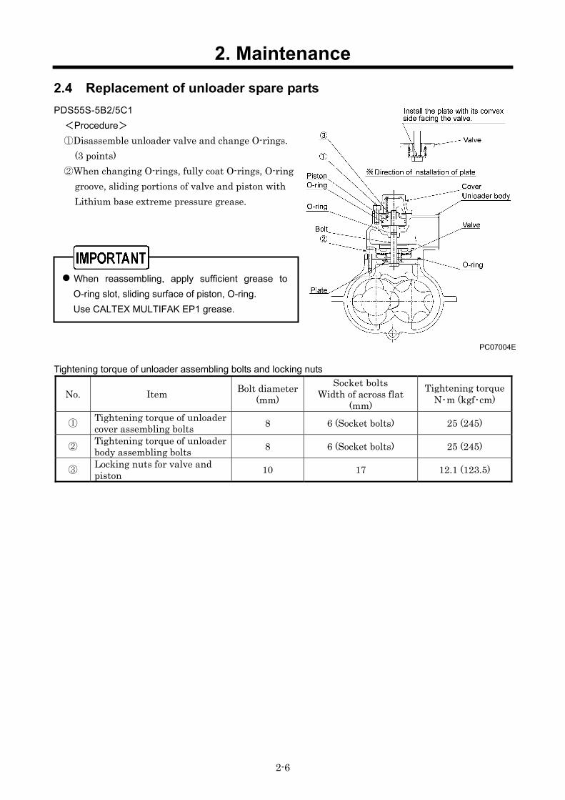
2.4 Replacement of unloader spare parts PDS55S-5B2/5C1
<Procedure>
①Disassemble unloader valve and change O-rings. (3 points)
②When changing O-rings, fully coat O-rings, O-ring groove, sliding portions of valve and piston with Lithium base extreme pressure grease.
When reassembling, apply sufficient grease to O-ring slot, sliding surface of piston, O-ring. Use CALTEX MULTIFAK EP1 grease.
Tightening torque of unloader assembling bolts and locking nuts
No. Item Bolt diameter (mm)
Socket bolts Width of across flat
(mm) Tightening torque
N・m (kgf・cm)
① Tightening torque of unloader cover assembling bolts 8 6 (Socket bolts) 25 (245)
② Tightening torque of unloader body assembling bolts 8 6 (Socket bolts) 25 (245)
③ Locking nuts for valve and piston 10 17 12.1 (123.5)
PC07004E

2. Maintenance
2-7
PDS75,100S[SC]-5B2/5C1, PDS130S[SC]-5B2, PDS175S[SC]-5B2
<Procedure>
①Disassemble unloader, and replace O-rings (2 points) and bushing with new ones.
②When changing O-rings, fully coat O-rings, O-ring groove, sliding portions of valve and piston with Lithium base extreme pressure grease.
③When re-assembling it, coat the seating faces of unloader body and cover with liquid sealing packing LOCTITE FMD127 and retighten them according to the specified torque mentioned in the following table.
PDS175S[SC]-5C1
<Procedure>
Supply grease to O-ring“1”,“2”,“3”,“4”after replacement.
When reassembling, apply sufficient grease to O-ring slot, sliding surface of piston, O-ring. Use CALTEX MULTIFAK EP1 grease.
Tightening torque of unloader assembling bolts
No. Item Bolt diameter (mm)
Socket bolts Width of across flat
(mm) Tightening torque
N・m (kgf・cm)
① Tightening torque of unloader cover assembling bolts 10 8 49 (485)
② Unloader inner cover assembling bolts 8 6 25 (245)
PC07006-1
PDS75S-5C1
PC09008E
2. Maintenance
2-8
PC07001E
PC09004
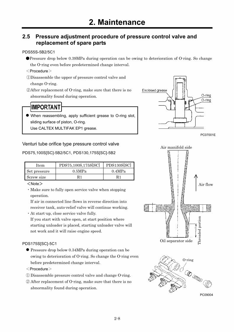
2.5 Pressure adjustment procedure of pressure control valve and replacement of spare parts
PDS55S-5B2/5C1 Pressure drop below 0.39MPa during operation can be owing to deterioration of O-ring. So change
the O-ring even before predetermined change interval. <Procedure> ①Disassemble the upper of pressure control valve and
change O-ring. ②After replacement of O-ring, make sure that there is no
abnormality found during operation.
When reassembling, apply sufficient grease to O-ring slot, sliding surface of piston, O-ring. Use CALTEX MULTIFAK EP1 grease.
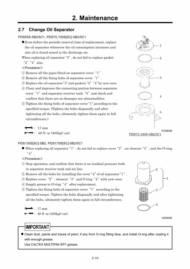
Venturi tube orifice type pressure control valve
PDS75,100S[SC]-5B2/5C1, PDS130,175S[SC]-5B2
Item PDS75,100S,175S[SC] PDS130S[SC] Set pressure 0.5MPa 0.4MPa Screw size R1 R1 <Note> ・Make sure to fully open service valve when stopping
operation. If air in connected line flows in reverse direction into receiver tank, auto-relief valve will continue working.
・At start-up, close service valve fully. If you start with valve open, at start position where starting unloader is placed, starting unloader valve will not work and it will raise engine speed.
PDS175S[SC]-5C1 Pressure drop below 0.34MPa during operation can be owing to deterioration of O-ring. So change the O-ring even before predetermined change interval.
<Procedure> ① Disassemble pressure control valve and change O-ring. ② After replacement of O-ring, make sure that there is no
abnormality found during operation.
Air flow
Oil separator side
Air manifold side
Thre
aded
por
tion
O-ring

2. Maintenance
2-9
H000057
PC08057
2.6 Inspection/replacement of auto relief valve spare parts PDS55~100S[SC]-5B2/5C1, PDS130,175S[SC]-5B2 Disassemble and clean the component, and check O-ring“1”, “2”,“3”and needle valve“4”.Then, replace O-ring 1”,“2”,3”and needle valve“4”if its rubber is hardened.
When reassembling, apply sufficient grease to O-ring slot, sliding surface of piston, O-ring. Use CALTEX MULTIFAK EP1 grease.
PDS175S[SC]-5C1
Disassemble and clean the component, and check O-ring“1”,“2”,“3”and needle valve“4”. Then, replace O-ring“1”,“2”,“3” and rubber on the needle valve“4”, if hardened.
1
2
4
3
1 2
3 4
Auto-relief valve
1 2
3 4
Vacuum relief valve
2. Maintenance
2-10
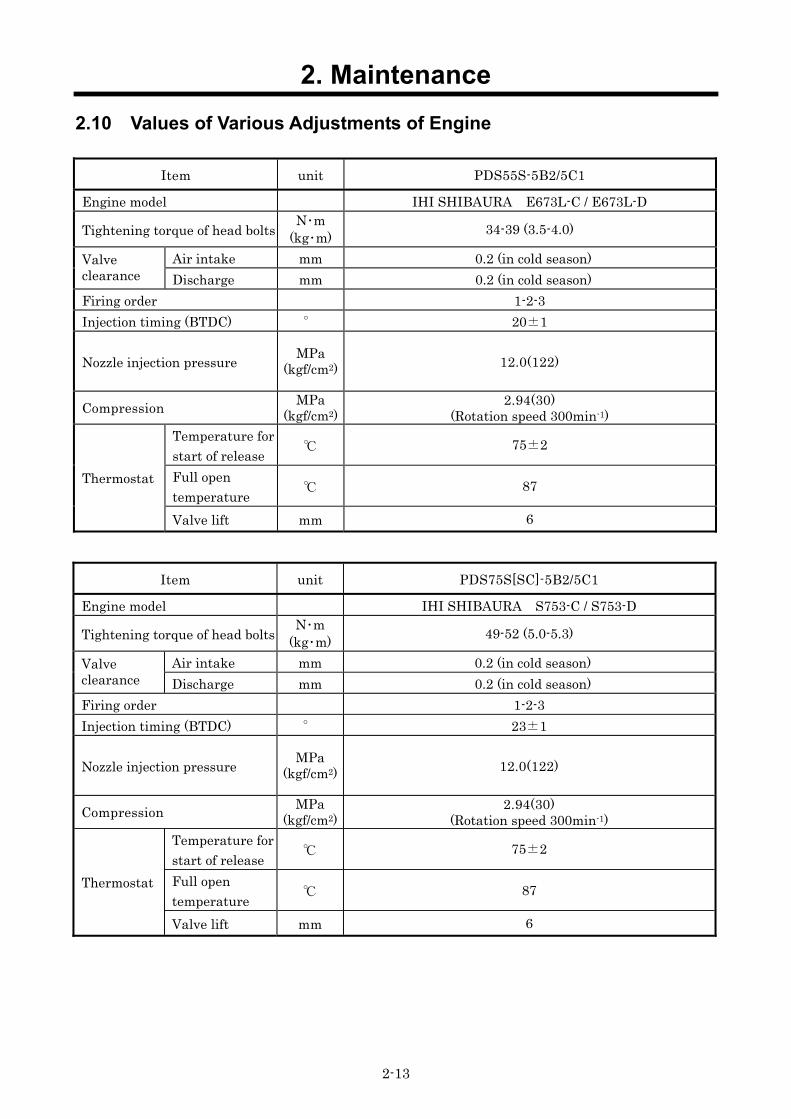
2.7 Change Oil Separator PDS55S-5B2/5C1, PDS75,100S[SC]-5B2/5C1 Even before the periodic interval time of replacement, replace the oil separator whenever the oil consumption increases and also oil is found mixed in the discharge air.
When replacing oil separator“3”, do not fail to replace gasket“2”“4”also. <Procedure>
① Remove all the pipes fitted on separator cover“1”. ② Remove all the fixing bolts of separator cover“1”. ③ Replace the oil separator“3”and gaskets“2”“4”by new ones. ④ Clean and degrease the connecting portion between separator
cover“1”and separator receiver tank“5”and check and confirm that there are no damages nor abnormalities.
⑤ Tighten the fixing bolts of separator cover“1”according to the specified torque. (Tighten the bolts diagonally and after tightening all the bolts, ultimately tighten them again in full circumference.)
: 17 mm : 49 N・m (485kgf・cm)
PDS130S[SC]-5B2, PDS175S[SC]-5B2/5C1 When replacing oil separator“1”, do not fail to replace cover“2”, an element“3”, and the O-ring“4”.
<Procedure>
① Stop operation, and confirm that there is no residual pressure both in separator receiver tank and air line.
② Remove all the bolts for installing the cover“2”of oil separator“1”. ③ Replace cover“2”, element“3”and O-ring“4”with new ones. ④ Supply grease to O-ring“4”after replacement. ⑤ Tighten the fixing bolts of separator cover“1”according to the
specified torque. Tighten the bolts diagonally and after tightening all the bolts, ultimately tighten them again in full circumference.
: 17 mm : 49 N・m (485kgf・cm)
Clean dust, paints and traces of paint, if any from O-ring fitting face, and install O-ring after coating it with enough grease. Use CALTEX MULTIFAK EP1 grease.
PC08058
PDS75,100S-5B2/5C1
1 2
3 4 5
H000056
2 3
4
1

2. Maintenance
2-11
2.8 Change of pellet assembly of by-pass valve (PDS175S only) By-pass valve fitted on this unit is of full bore type. While the unit is used for normal operation, it is not to perform periodical replacement of the Inner pellet assembly, but when such trouble as excessive rise of compressor oil temperature, it becomes necessary to replace it, in accordance with the following procedures.
<Procedure>
① First stop the unit and make sure that there is no residual pressure left in the separator receiver tank.
② After confirming that temperature of compressor oil is lowered enough, take off the cover and remove pellet assembly and O-ring.
③ Replace the pellet assembly and O-ring by new ones. Install O-ring coated thinly with compressor oil.
④ Start operation and check the function of by-pass valve. (It functions well when delivery air temperature will not rise abnormally.)
Actuating temperature
By-pass valve fully closing temperature
82±3 89±2
To air end
7
1.Oil filter body 2.Oil filter 3.Cover 4.Pellet ASS'Y 5.Plug 6.Relief valve ASS'Y 7.O-ring
From oil cooler
To oil cooler
Air end
Receiver tank

2. Maintenance
2-12
2.9 Clean inside of Fuel Tank Condensate is caused and accumulated at the bottom of fuel tank, owing to churning of dust or dirt
mixed when fuel oil is fed and water drop caused while fuel oil tank is used for a long time. When any condensate is found afloat and fuel filter gets clogged too fast, fuel oil tank should be cleaned after condensate is removed from fuel oil tank even before the specified cleaning interval time.
<Procedure>
① Open drain valve to remove fuel oil from fuel tank. ② Dismantle the door and side covers of bonnet. ③ Remove fuel pipes and wires connected to fuel tank. ④ Remove belt holding fuel tank and remove tank. ⑤ Insert cleansing nozzle through fuel filler port or drain port
for cleaning tank. ⑥ After cleaning job is finished, install fuel tank from which
water or the like should be completely removed.
PDS130S-5B2
PC08059
2. Maintenance
2-13
2.10 Values of Various Adjustments of Engine
Item unit PDS55S-5B2/5C1
Engine model IHI SHIBAURA E673L-C / E673L-D
Tightening torque of head bolts N・m (kg・m) 34-39 (3.5-4.0)
Air intake mm 0.2 (in cold season) Valve clearance Discharge mm 0.2 (in cold season) Firing order 1-2-3 Injection timing (BTDC) ° 20±1
Nozzle injection pressure MPa (kgf/cm2) 12.0(122)
Compression MPa (kgf/cm2)
2.94(30) (Rotation speed 300min-1)
Temperature for start of release 75±2
Full open temperature 87 Thermostat
Valve lift mm 6
Item unit PDS75S[SC]-5B2/5C1
Engine model IHI SHIBAURA S753-C / S753-D
Tightening torque of head bolts N・m (kg・m) 49-52 (5.0-5.3)
Air intake mm 0.2 (in cold season) Valve clearance Discharge mm 0.2 (in cold season) Firing order 1-2-3 Injection timing (BTDC) ° 23±1
Nozzle injection pressure MPa (kgf/cm2) 12.0(122)
Compression MPa (kgf/cm2)
2.94(30) (Rotation speed 300min-1)
Temperature for start of release 75±2
Full open temperature 87 Thermostat
Valve lift mm 6

2. Maintenance
2-14
Item unit PDS100S[SC]-5B2/5C1 PDS130S[SC]-5B2
Engine model IHI SHIBAURA S773L-C / S773L-D
IHI SHIBAURA N843L-C
Tightening torque of head bolts N・m (kg・m) 49-52 (5.0-5.3) 98-103 (10-10.5)
Air intake mm 0.2 (in cold season) Valve clearance Discharge mm 0.2 (in cold season) Firing order 1-2-3 Injection timing (BTDC) ° 24±1 22±1
Nozzle injection pressure MPa (kgf/cm2) 13.9(142) 14.7(150)
Compression MPa (kgf/cm2)
2.94(30) (Rotation speed 300min-1)
Temperature for start of release 75±2 71±2
Full open temperature 87 82 Thermostat
Valve lift mm 6 8
Item unit PDS175S[SC]-5B2/5C1
Engine model NISSAN DIESEL 2A-TD27/TD27B-08 First time 49.0 - 58.8 (5.0 - 6.0)
Tightening torque of head bolts N・m (kg・m) Second time 98.1 – 107.9 (10.0 - 11.0)
Air intake mm 0.35 (in warm season) Valve clearance Discharge mm 0.35 (in warm season) Firing order 1-3-4-2 Injection timing (BTDC) ° 16 / 5
Nozzle injection pressure MPa (kgf/cm2) 9.81(100)
Standard MPa (kgf/cm2) 2.94(30) (Rotation speed 200min-1)
Limited value 2.45(25) Compression Working limit MPa
(kgf/cm2) Each cylinder limit value 0.29(3) Temperature for start of release 71 Full open temperature 85 Thermostat
Valve lift mm 8

3. Electric System
3-1
3.1 Engine electric appliances 3.1.1 Instrument panel ASS’Y PDS55~130S[SC];Part Number:36100 07200
A08060
A08061
(1) Residual fuel oil in fuel gauge Pointer position Resistance (Ω) Remaining fuel (%)
1/10 95.2 10 2/10 70.3 20 3/10 54.4 30 4/10 43.1 40 5/10 32.6 50 6/10 24.5 60 7/10 19.1 70 8/10 12.4 80 9/10 6.9 90
10/10 3 100
Instrument panel ASS’Y
1 2
678
5 4 3
5 6 7 8 6 7 8 9 10 J1 J2
1 2 3 4 1 2 3 4 5
<Instruments> 1. Fuel level gauge 2. Elapsed time indicator <Indicator lamp> 3. Preheating
<Warning lamp> 4. Charging 5. Fuel residual level <Emergency stop lamp> 6. Discharge air temperature 7. Engine oil pressure 8. Coolant temperature
Cable connection

3. Electric System
3-2
(2) List of functions
Pin No. Line color Connection Remark
1 - NIL 2 - NIL 3 - NIL 4 - NIL 5 B Earth
6 Y/G Solenoid No.2 terminal
It is electrically connected during normal operation. When emergency stop system works, internal contact between J1-5 (ground connection) and J1-6 terminal will be “OFF” and power supply to stop solenoid will be cut and it will cause engine emergency stop.
7 G/Y 10A Fuse Power supply
Conn
ecto
r J1
8 L/Y Sending unit No.1 terminal It detects residual fuel. 1 - NIL
2 L/R ※1 Engine oil pressure switch
It is electrically connected during normal operation. When engine oil pressure drops and oil pressure switch is “OFF”, power supply to J2-2 terminal will be cut. Then emergency stop system functions to break internal contact between J1-5 (ground connection) and J1-6 terminal to cut power supply to stop solenoid, causing engine emergency stop. Set pressure of emergency stop oil pressure
below 98.1kPa. 3 G Glow plug During preheating operation, it supplies power to
light preheat lamp.
4 Y/B Dynamo regulator Male terminal
Bad charging, Charging lamp is caused to light on. During normal operation, warning lamp for bad charging will not go on because both poles of warning lamp J2-4 terminal) are equally potential. When there is no voltage coming from female connector of dynamo regulator, current flows to dynamo regulator to make warning lamp light on.
5 L/B Coolant temp. switch
It is electrically connected during normal operation. When engine water temperature switch becomes “OFF” with rise of engine coolant temperature, power supply is cut to J2-5 terminal. It actuates emergency stop circuit to break the internal contact between J1-5 (ground connection) and J1-6 terminal and then power supply is cut to stop solenoid to cause engine emergency stop. Emergency stop set temperature 110.
6 - NIL 7 - NIL
8 L/W Discharge air temp. switch
It is electrically connected during normal operation. When discharge air temperature switch becomes “OFF” with rise of discharge air temperature, power supply is cut to J2-8 terminal. It actuates emergency stop circuit to break the internal contact between J2-5 (ground connection) and then power supply is cut to stop solenoid to cause engine emergency stop. Emergency stop set temperature 120.
9 W/G Dynamo regulator No.4 terminal
Generating signal inputted Inputting of generating signal actuates both hour-meter and detection circuit (timer built-in) for abnormal oil pressure.
Conn
ecto
r J2
10 - NIL ※1:Detection circuit for abnormal oil pressure will start to work 10 seconds after detecting generating
signal of alternator with J2-9 terminal.

3. Electric System
3-3
PDS175S[SC]
PC09006-1
(1) Specification Range of voltage in use DC10~16V(at12V type) Temperature range in use -20- +60
PC09013
1 2 3
6 7 8 4 5
<Instruments>
1.Discharge air pressure gauge
2.Fuel level gauge 3.Elapsed time indicator <Indicator lamp> 4.Preheating
<Warning lamp>
5.Charging <Emergency stop lamp>
6.Engine oil pressure 7.Coolant temperature 8.Discharge air temperature 9.Fuel drain
9
[Wiring diagram inside instrument panel]
Part Number:36100 06700

3. Electric System
3-4
(2) List of functions
Pin No. Line color Connection Remark
1 W/R 10A Fuse Power supply for instrument panel ASS’Y.
2 G/W Solenoid relay No.1 terminal
When starter switch is “ON”, voltage is applied to No.1 terminal of solenoid relay. When “OFF”, it is not electrically supplied. Electricity is cut when emergency stop switch is “ON”.
3 G/R Engine oil pressure switch Coolant temperature switch
During normal operation there is no electrical flow.When engine oil pressure switch is “ON”, electricity flows between No.3 terminal and No.8 terminal and when cooling water temperature switch is “ON”, it flows between No.3 terminal and No.5 terminal. Thus emergency stop lamp goes on and engine is brought to an emergency stop.
4 G/Y Coolant temperature switch Discharge air temperature switch
During normal operation there is no electrical flow.When discharge air temperature switch is “ON”, electricity flows between No.4 terminal and No.5 terminal and when cooling water temperature switch is “ON”, it flows between No.4 terminal and No.8 terminal. Thus emergency stop lamp goes on and engine is brought to an emergency stop.
5 G/W Engine oil pressure switch
During operation electricity is supplied between No.5 terminal and No.8 terminal. When power is not supplied to No.5 terminal, engine oil pressure drop emergency stop lamp goes on and engine is brought to emergency stop.
6 L/R Glow controller No.4 terminal During preheating operation, it causes preheat lamp to go on.
7 R Alternator No.1 terminal Bad charging→Charging lamp is caused to light on.
8 W/R Discharge air temperature switch
During operation electricity is supplied between No.5 terminal and No.8 terminal. When power is not supplied to No.8 terminal, discharge air temperature rise emergency stop lamp goes on and engine is brought to emergency stop.
9 B Earth
10 Y/B Sending unit No.1 terminal When starter switch is switched “ON”, it shows residual fuel in the fuel tank.

3. Electric System
3-5
3.1.2 Alternator (Dynamo) PDS55~130S[SC]
PC08062
(1) List of functions PDS55S-5B2/5C1, PDS75,100S[SC]-5B2/5C1
Pin No. Line color Connection Remark
1 R/B Dynamo regulator No.1 terminal 2 R/W Dynamo regulator No.3 terminal
Outputting charging voltage to dynamo regulator.
PDS130S[SC]-5B2
Pin No. Line color Connection Remark
1 R/B Dynamo regulator CN2-2 terminal 2 R/B Dynamo regulator CN2-1 terminal 3 R/W Dynamo regulator CN2-4 terminal 4 R/W Dynamo regulator CN2-3 terminal
Outputting charging voltage to dynamo regulator.
(2) Judgement of alternator (Dynamo) functions
Test method Normal value Measure voltage at no load condition during operation (at full speed). (Measure AC current between 2 dynamo lead lines.)
Above AC30V
Check for electric conductivity of coiled line while stopping. (Check for electric conductivity between 2 dynamo lead lines.) Electric conductivity found. Measure insulation resistance. (Measure insulation resistance between 1 dynamo lead line and coil plate.)
More than 3MΩ
Remove V-belt, and turn pulley by hand. Due to magnetism repulsion occurs 12 times reactions per one turn, but it turns comparatively smoothly.
PDS55,75,100S[SC]-5B2/5C1
PDS130S[SC]-5B2
VIEW-A

3. Electric System
3-6
PDS175S[SC]-5B2/5C1 [Dynamo regulator (IC type)]
(1)List of functions
Pin No. Line color Connection Remark
BAT R Starter motor B terminal Power for charging voltage.
R R/W 10A Fuse (Through joint connector)
Detect output voltage from alternator and adjust the current flowing to rotor coil.
L W Hour meter Signal output for hour meter.
※ P Y/G Controller CN2-17 terminal
For separating starter motor. When frequency of P terminal exceeds 190±10Hz, starter relay contact is switched through controller, and it disengages starter motor.
E B Earth ※:For diagnosing P terminal, check the generating voltage between P-E terminal and it is normal if the
voltage detected is about DC7.2V.
(2) Judgement of alternator functions Checking method by measuring battery terminal
at full load operation Normal Value
Measure the battery terminal voltage at full load operation. 14.4±0.3V
Cable connection
3. Electric System
3-7
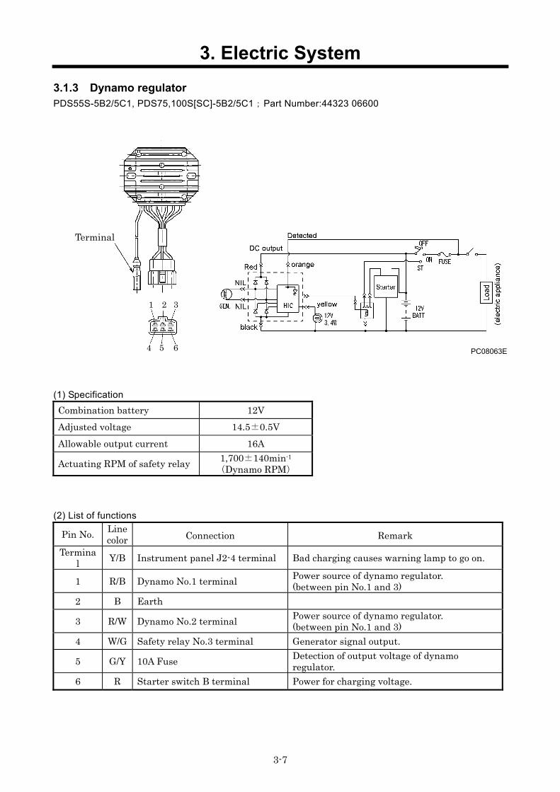
3.1.3 Dynamo regulator PDS55S-5B2/5C1, PDS75,100S[SC]-5B2/5C1;Part Number:44323 06600
PC08063E
(1) Specification
Combination battery 12V Adjusted voltage 14.5±0.5V Allowable output current 16A
Actuating RPM of safety relay 1,700±140min-1
(Dynamo RPM)
(2) List of functions
Pin No. Line color Connection Remark
Terminal Y/B Instrument panel J2-4 terminal Bad charging causes warning lamp to go on.
1 R/B Dynamo No.1 terminal Power source of dynamo regulator. (between pin No.1 and 3)
2 B Earth
3 R/W Dynamo No.2 terminal Power source of dynamo regulator. (between pin No.1 and 3)
4 W/G Safety relay No.3 terminal Generator signal output.
5 G/Y 10A Fuse Detection of output voltage of dynamo regulator.
6 R Starter switch B terminal Power for charging voltage.
1 2 3
Terminal
4 5 6

3. Electric System
3-8
PDS130S[SC]-5B2;Part Number:44323 06900
PC08064E
(1) Specification
Combination battery 12V Adjusted voltage 14.5±0.5V Allowable output current 27A
Actuating RPM of safety relay 2,150±140min-1
(Dynamo RPM)
(2) List of functions
Pin No. Line color Connection Remark
Terminal Y/B Instrument panel J2-4 terminal Bad charging causes warning lamp to go on. 1 B Earth
2 G/Y 10A Fuse Detection of output voltage of dynamo regulator.
3 R Starter switch B terminal Power for charging voltage. 4 B Earth 5 W/G Safety relay No.3 terminal Generator signal output. Co
nnec
tor C
N1
6 R Starter switch B terminal Power for charging voltage. 1 R/B Dynamo No.2 terminal 2 R/B Dynamo No.1 terminal 3 R/W Dynamo No.4 terminal
Conn
ecto
r CN
2
4 R/W Dynamo No.3 terminal
Power source of dynamo regulator.
1 2 3 1 2 Terminal
4 5 6 3 4
CN1 CN2

3. Electric System
3-9
(3) Diagnosing when battery charging warning lamp lights PDS55S-5B2/5C1, PDS75,100S[SC]-5B2/5C1, PDS130S[SC]-5B2
Cable disconnected
Abnormal : same voltage as battery voltage when stopping.
Recharging battery.
Normal: 12V
Measure terminal voltageof alternator (dynamo).
Disconnection of charging circuit PDS55-100S[SC]:
Disconnection between dynamo regulator No.6 terminal and battery
PDS130S[SC]: Disconnection between dynamo regulator No3, 6 and battery
Measure charging voltage of dynamo regulator during operation and measure voltage of output terminal.
Normal: about 14V
Normal: about 14V
Repair disconnected line of warning lamp circuit (dynamo regulator male connector and instrument panel J2-4 terminal).
Repairing alternator because it is faulty.
Repair alternator (dynamo)
Normal value: more than AC30V
Repair dynamo regulator
Check for any disconnection between alternator (dynamo) and dynamo regulator.
Repair disconnection
Not cable disconnected
Measure battery voltage when engine stops.
Abnormal : less than 12V
Abnormal : less than
AC30V
Measure battery voltage during operation.
Abnormal : same voltage as battery voltage when stopping.
Cable disconnected
Not cable disconnected
Check charging warning lampcircuit.

3. Electric System
3-10
PDS175S[SC]-5B2/5C1
Recharging battery.
Abnormal : less than 12V
Normal: 12V
Measure battery voltage when engine stops.
Repairing alternator because it isfaulty.
Normal: about 14V
Abnormal : same voltage as battery voltage when stopping. Measure the voltage of
alternator BAT terminal during operation.
Abnormal : less than 7.2V
Abnormal : same voltage as battery voltage when stopping. Check charging circuit (connection
between alternator BAT terminal to battery).
Normal: about 14V
Repairing alternator because it is faulty.
Normal: about 7.2V
Check charging warning lampcircuit.
Disconnected check and confirm waning lamp circuit (P terminal - controller CN2-17 terminal).
Cable disconnected
Repairing alternator because it is faulty.
Not cable disconnected
Check the voltage between alternator P-E terminals at no load.
Measure battery voltage during operation.

3. Electric System
3-11
3.1.4 Glow controller PDS55S-5B2/5C1, PDS75,100S[SC]-5B2/5C1, PDS130S[SC]-5B2;Part Number:44346 12500
PC08065E
(1) Coolant temperature・glow instantaneous characteristic ( at the time of key-OFF-ON)
Water temp. Lamp lights・glow time t (sec)-15 8.9 0 5.8 20 2.7
(2) List of functions
Pin No. Line color Connection Remark
1 W/B Starter switch R2 terminal Detection of starter signal 2 - NIL 3 G/Y 10A Fuse Power supply 4 G/R Water temperature sensor Detection of water temperature
5 G/W Glow relay No.3 terminal
Power supply for glow relay. During preheating operation, connect to No.6 ground connection and it will be magnetically excited. When the start signal is inputted to No.1 terminal, it preheats, regardless of coolant temperature.
6 B Earth
(3) Chart of function ※(st) st
Starter
Switch
t
Lamp
t
Glow
※:The chart marked ※1shows the function chart at which the starter switch is placed at “ST” position.
ST
ON
OFF
ON
OFF
ON
OFF
3. Electric System
3-12
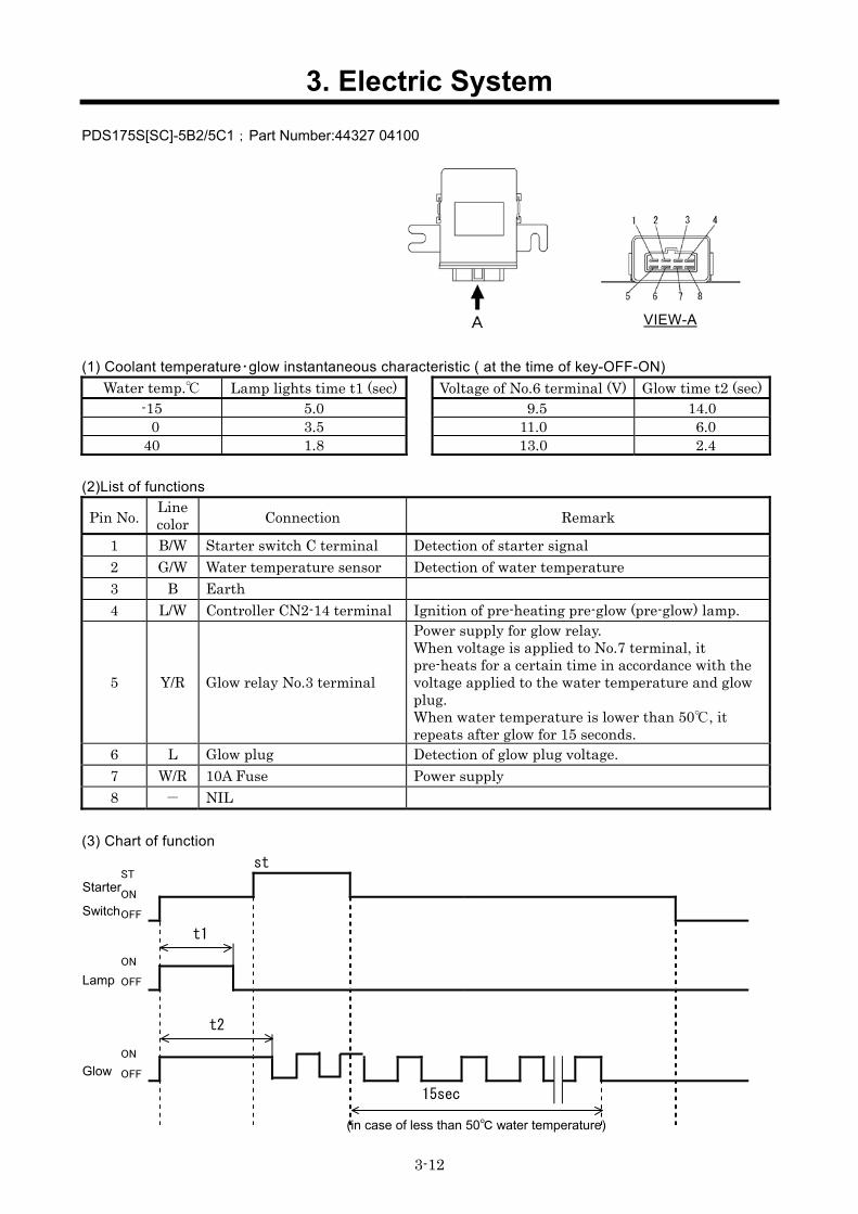
PDS175S[SC]-5B2/5C1;Part Number:44327 04100
(1) Coolant temperature・glow instantaneous characteristic ( at the time of key-OFF-ON) Water temp. Lamp lights time t1 (sec) Voltage of No.6 terminal (V) Glow time t2 (sec)
-15 5.0 9.5 14.0 0 3.5 11.0 6.0 40 1.8 13.0 2.4
(2)List of functions
Pin No. Line color Connection Remark
1 B/W Starter switch C terminal Detection of starter signal 2 G/W Water temperature sensor Detection of water temperature 3 B Earth 4 L/W Controller CN2-14 terminal Ignition of pre-heating pre-glow (pre-glow) lamp.
5 Y/R Glow relay No.3 terminal
Power supply for glow relay. When voltage is applied to No.7 terminal, it pre-heats for a certain time in accordance with the voltage applied to the water temperature and glow plug. When water temperature is lower than 50, it repeats after glow for 15 seconds.
6 L Glow plug Detection of glow plug voltage. 7 W/R 10A Fuse Power supply 8 - NIL
(3) Chart of function st
Starter
Switch
t1
Lamp
t2
Glow
15sec
VIEW-A
ST
ON
OFF
ON
OFF
ON
OFF
(in case of less than 50 water temperature)

3. Electric System
3-13
3.1.5 Water temperature sensor for preheating PDS55S-5B2/5C1, PDS75,100S[SC]-5B2/5C1, PDS130S[SC]-5B2;Part Number:44334 14800
Coolant temperature・Resistance characteristics
Water temp. Resistance (kΩ) -10 10.0 20 2.5 50 0.785
PDS175S[SC]-5B2/5C1;NISSAN DIESEL Part Number:22630-10G00
Coolant temperature・Resistance characteristics
Water temp. Resistance (kΩ) -10 9.2 20 2.5 50 0.84
3.1.6 Discharge air temperature switch PDS55S-5B2/5C1, PDS75,100S[SC]-5B2/5C1, PDS130,175S[SC]-5B2;Part Number:44334 16500
Specification
OFF 120±2 Setting temp. ON 110±2
Contact type B contact switch (Contact “OFF” in excess of set pressure)
3.1.7 Engine coolant temperature switch PDS55S-5B2/5C1, PDS75,100S[SC]-5B2/5C1, PDS130S[SC]-5B2;Part Number:44334 17500 PDS175S[SC]-5B2 ;Part Number:44334 09300
Specification
OFF 110±2 Setting temp. ON 103±2
Contact type B contact switch (Contact “OFF” in excess of set pressure)
PC09007

3. Electric System
3-14
3.1.8 Discharge air temperature sensor, Coolant temperature sensor PDS175S[SC]-5C1;Part number:44364 06500
3.1.9 Engine oil pressure switch PDS55S-5B2/5C1, PDS75,100S[SC]-5B2/5C1, PDS130S[SC]-5B2;Part Number:44328 06700
Specification
Setting pressure 98.1kPa(1.0kgf/cm2)
Contact type A contact switch (Contact “ON” in excess of set pressure)
PC08066
PDS175S[SC]-5B2/5C1;Part Number:44328 19100
Specification
Setting pressure 0.06MPa(0.6kgf/cm2)
Contact type A contact switch (Contact “ON” in excess of set pressure)
Time lag ・10 seconds after engine starts. ・2 seconds during operation
Characteristic of temperature resistance
Water temp.
Resistance (kΩ)
Permissible Value (%)
80 1,300 ±7 95 840 ±6 110 560 ±5 115 490 ±6
PC08033
《Note》Take care not to tighten excessively. Less than 1.96N・m(20kgf・cm)
PC08034
Engine

3. Electric System
3-15
3.1.10 Sending unit PDS55S-5B2/5C1 PDS75S[SC]-5B2/5C1
PDS100S[SC]-5B2/5C1 PDS130S[SC]-5B2 PDS175S[SC]-5B2/5C1 Pointer
position Remaining fuel (L) Remaining fuel (L) Remaining fuel (L)
Resistance (Ω)
E 3.0 3.5 11.5 110.0 1/2 8.5 16.5 38.0 32.5 F 15.0 25.0 63.5 3.0
PDS55S-5B2/5C1;Part Number:36159 02101
PC08067E

3. Electric System
3-16
PDS75,100S[SC]-5B2/5C1;Part Number:36159 03000
PC08068E

3. Electric System
3-17
PDS130S[SC]-5B2, PDS175S[SC]-5B2/5C1;Part Number:36159 02202
PC08069E

3. Electric System
3-18
3.1.11 Fuel air-bleeding electromagnetic pump PDS55S-5B2/5C1, PDS75,100S[SC]-5B2/5C1, PDS130S[SC]-5B2;Part Number:43650 01500 PDS175S[SC]-5B2/5C1 ;Part Number:43650 01900
PC08087
(1) Specification
PDS55~130S PDS175S Rated voltage 12V
Operating current 1.5A(MAX) Delivery capacity More than 0.8L/min More than 0.4L/min
(2) Functions When the key switch is turned “ON”, electromagnet pump No.2 terminal will be electrically conducted to work. On the contrary, when “OFF” or emergency stop circuit works, solenoid relay No.3 is switched to cut connection to electronic pump solenoid.
3.1.12 Fuel filter PDS175S[SC]-5C1;Part number:43540 07400
PC08038E

3. Electric System
3-19
PC08082
3.1.13 Stop solenoid PDS55,75,100,130S[SC]-5B2
PDS55S,75,100S[SC]-5C1
(1) Specification
PDS55S-5B2 PDS75,100,130S[SC]-5B2
PDS55S-5C1 PDS75,100S[SC]-5C1
Maker HITACHI TDS Rated voltage 12V 12V
Pull side Less than 25A 3.75A Rated current Holding side less than 1A 0.566A
(2) List of functions Pin No. Line color Connection Remark
1 (-) B Earth 2 (1) L Starter switch R2 terminal Pull coil 3 (2) Y/L Solenoid relay No.3 terminal Holding coil
( ) show the pin number, also connection of PDS55,75,100S[SC]-5C1. PDS55, 75,100S[SC]-5C1 are not equipped with stop solenoid because they are connected to ground.
(3) Functions When key switch is “ON”, stop solenoid No.3 terminal (holding circuit) is electrically conducted. [For PDS55, 75,100S/SC-5C1, No.2 terminal is electrically conducted.] When key switch is turned to “START”, stop solenoid No.2 terminal is electrically conducted. [For PDS55, 75,100S/SC-5C1, No.1 terminal is electrically conducted.] And the plunger inside stop solenoid is pulled to open the rack of engine fuel filler port. After engine starts, rack of fuel filler port is kept open because stop solenoid No.3 terminal (holding circuit) is electrically conducted [for PDS55, 75,100S/SC-5C1, No.2 terminal is electrically conducted.] When key switch is “OFF” or emergency stop circuit functions, contact of solenoid relay No.3 terminal is switched to cut electric conduction to stop solenoid. Thus fuel supply to engine is cut to make engine stop.
Caution upon installation of stop solenoid Replace seal washer with new one, which is to be fitted on the fitting face of stop solenoid. Screw in stop solenoid from the back of cylinder block (back of No.3 injection pump rack) and tighten it according to the set torque. Tighten torque 15.0-20.0 N・m (1.5-2.0 kg・m)
Cable connection
PC08086EPC08084
PC08085
Numbers in parenthesis show connector pin numbers of PDS55,75,100S[SC]-5C1.

3. Electric System
3-20
3.1.14 Stop motor PDS175S[SC]-5B2;Part number:44358 01200
PC08040-1
List of functions
Pin No. Line color Connection P1 LY Stop motor relay No.6 terminal (NC) P2 LW Stop motor relay No.5 terminal (NO) E B Earth A L Stop motor relay No.3 terminal (COM) X - NIL B LR 20A Fuse (Power supply)
NIL
3. Electric System
3-21
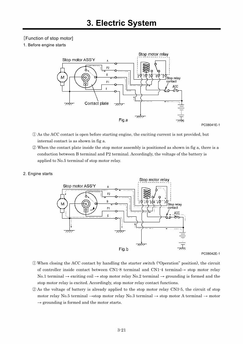
[Function of stop motor] 1. Before engine starts
PC08041E-1
① As the ACC contact is open before starting engine, the exciting current is not provided, but internal contact is as shown in fig a.
② When the contact plate inside the stop motor assembly is positioned as shown in fig a, there is a conduction between B terminal and P2 terminal. Accordingly, the voltage of the battery is applied to No.5 terminal of stop motor relay.
2. Engine starts
PC08042E-1
① When closing the ACC contact by handling the starter switch (“Operation” position), the circuit of controller inside contact between CN1-8 terminal and CN1-4 terminal→ stop motor relay No.1 terminal → exciting coil → stop motor relay No.2 terminal → grounding is formed and the stop motor relay is excited. Accordingly, stop motor relay contact functions.
② As the voltage of battery is already applied to the stop motor relay CN3-5, the circuit of stop motor relay No.5 terminal →stop motor relay No.3 terminal → stop motor A terminal → motor → grounding is formed and the motor starts.

3. Electric System
3-22
3. Rotation of contact plate
PC08043E-1
① When motor begins to rotate, the worm fitted to the motor shaft rotates and at the same time worm wheel rotates.
② The worm wheel and contact plate are interconnected and so it continues to rotate as shown in Fig C.
4. Stop of contact plate rotation
PC08044E-1
① When the contact plate turns 180˚ degree from the state at which it stays, the electrical conduction disappears between B and P2 terminal as shown in Fig.d, P2 terminal is connected to the grounding side. Further, it follows that the armature of the motor gets short-circuited and so it is electrically braked so that the contact plate stops surely at the constant position
② At the same time worm rotation is reduced by worm wheel, and further the rotation will be changed for reciprocal movement via the lever. The stroke extends the wire to move the fuel lever fitted at the injection pump to open the fuel circuit.
③ When the contact plate stays at the position shown in fig d, the conduction appears between B and P1 terminal and so the voltage of battery is applied to stop motor relay No.6 terminal.

3. Electric System
3-23
5. Engine stops (normal stop)
PC08045E-1
① To stop engine, handle starter switch to open ACC contact (“Stop” position) so that excitation circuit of stop motor relay may be released to move the contact point as shown in Fig e.
② As the voltage of battery is already applied to stop motor relay No.6 terminal, the circuit of stop motor relay No.3 terminal →stop motor A terminal → motor → grounding is formed and so the motor turns and at the same time the contact plate also turns as shown in the fig f.
③ The contact plate continues to turns from 180˚ position shown Fig e to the 360˚ position in Fig a via Fig f position. At the same time when the contact plate rotates the wire is pulled to close fuel line circuit by the fuel line connected to injection pump to close the fuel circuit to stop engine.
④ Motor and contact plate stop to rotate at specified position in Fig a, and return to the position in the clause “ 1. Before engine starts ”.
6. Emergency stop When any abnormalities are found in engine oil pressure, water temperature and discharge air temperature, controller emergency stop circuit functions, interior contact (RY1) starts to function to open the switch and to release stop motor relay exciting circuit. The process till “5.engine stops” is same after engine stop (normal stop).

3. Electric System
3-24
PDS175S[SC]-5C1
PC08039
(1) Specification
Rated voltage DC12V Power consumption 16W
Current 1.33A Pull・Holding
Resistance 9.02Ω
1. Replacement of stop solenoid Stop solenoid may intervene with dumper proof (full load adjusting portion) when it is being replaced. Therefore, it is impossible to remove stop solenoid only. When it is necessary to remove it, it is better to contact Bosch Service Department or injection pump assembly.
2. Position of strainer installment inside VE pump Injection pump is equipped with a strainer in connector of fuel return pipe. This strainer is provided to prevent clogging of the orifice (about 0.5mm) provided to keep the fuel pressure in the pump constant (Installation: one position).
Governor spring
Stop solenoid
Orifice Fuel return connector
Strainer
Full load adjusting screw
Cam disk Plunger Control sleeve
4. Troubleshooting
4-1
4.1 Repairing Procedures When performing failure diagnosis, pay special attention to the followings, observing general cautions.
4.1.1 Safety caution (1) Removing such cap and/or plug for receiver tank, fuel tanks and pipes where pressure is
loaded, stop the machine and relieve all the interior pressure. Install measuring instruments connected firmly.
(2) When doing the job with co-worker(s) together, make sure to give signal to the other person(s) and do not allow other persons to come near to the job site.
(3) Take care not to touch hot portions and not to be involved in turning portions.
4.1.2 Caution during failure diagnosis (1) Do not make haste to disassemble the unit
If the unit is disassembled urgently. ①You may disassemble the other portions which are not related with the trouble. ②The cause of trouble may be missing. The unnecessary reparations require more spare parts and man-hours, and reparation costs will increase more. What is worse, you will lose reliance or trust from clients,operators and users. Therefore, it is absolutely necessary to investigate the trouble more carefully in advance and to follow the required procedures for failure diagnosis.
(2) Ask the clients about the trouble in details In order to prevent misunderstanding and incorrect judgment about the trouble, it is necessary to ask users or operators about the following questions. ①Is there any other disorder than the trouble he has informed? ②Anything abnormal occurred before this trouble? ③Did this trouble happen unexpectedly? Or the unit had been operated in bad conditions before? ④When and how did this trouble occur? ⑤Had he repaired the unit before this trouble occurred? ⑥Did he not experience similar trouble before?
(3) Inspection items before starting diagnosis Sometimes such trouble may be caused owing to routine mishandling of the unit. Before starting failure diagnosis, check the following items. ①The engine runs short of engine oil or its oil is not dirty? ②Check each wire connection for any disconnection. ③Check the other portions for any damage.
(4) Confirmation of trouble
Discuss with user(s) and/or operator(s) sufficiently about the trouble. As a result, judge whether their judgment is based on the numerical comparison or sentimental basis. Make him (them) understand well the reparation or correction you have finished. Then check and confirm by yourself the cause of the trouble. Note) Never proceed any investigation or measurement which may cause further greater damage.

4. Troubleshooting
4-2
(5) Procedures of diagnosis
When you become well experienced, you can find out the cause easily during the process of confirmation (4). But easy understanding could cause unexpected failure. So check and judge it according to the following procedures. ①Check the easiest thing or portion first. ②Investigate the most possible cause. ③Check the other things connected to the trouble. ④Check for the possibility of any other troubles. ⑤Start proper and careful investigation on this trouble.
(6) Prevention of repeated occurrence of similar trouble Even if you have repaired the trouble, unless you get rid of the fundamental cause of the trouble, it will repeatedly occur. Therefore, perform full investigation of the trouble, and it is absolutely necessary to remove the basis of the trouble.
4.1.3 How to use the failure diagnosis
① In the troubleshooting column something abnormal is mentioned in lined parenthesis.
② In the troubleshooting column the cause of the said trouble is mentioned in dotted parenthesis.
③ In the troubleshooting column the countermeasures or treatment are mentioned in the double lined parenthesis.
④ 1 under each column means the index of explanation. For details, see 4.5 “Explanation of trouble diagnosis”
NO
NO
NO
OK
OK
OK
OK
1 2 3

4. Troubleshooting
4-3
4.2 Failures of compressor and engine 4.2.1 At start-up, starter rotates slowly
※1:When starter switch is placed at the “START” position, the battery is not normal if B terminal voltage decreases by 10V.
4.2.2 Receiver tank gauge pressure will not rise up to rated pressure during unloaded operation
Re-charge and or supply water/replace.
Check battery cable. Faulty cable.
Faulty starter motor.
Replace terminal or assembly.
Repair or replace assembly.
Normal Volt: more than 12V Gravity: more than 1.26
※1 Faulty
Error in operation Turn valve to operation side.
Start side
Operation side
Faulty adjustment of pressure Re-adjust pressure
Faulty pressure gauge
Faulty adjustment
Adjustment Replace it.
Faulty adjustment
Check oil separator for clogging. Faulty oil separator.
Differential pressure too much Replace it.
Normal
Faulty unloader. 1
Disassemble / clean or replace
Check battery voltage and specific gravity.
Faulty
Normal
Battery specific gravity too low or electrolyte short.
Check adjustment of pressure regulator.
Check position of starting unloader valve.
Change pressure gauge for replacement one, and re-adjust pressure gauge.
Adjustment

4. Troubleshooting
4-4
4.2.3 Engine revolutions will drop before pressure rises up to rated one
Malfunction of pressure regulator. Replace it.
Faulty adjustment of pressure Re-adjust pressure Check adjustment of
pressure regulator. Adjustment
Change pressure gauge for replacement one, and re-adjust pressure gauge.
Faulty pressure gauge
Faulty adjustment
Adjustment Replace it.
Faulty adjustment

4. Troubleshooting
4-5
4.2.4 Engine will not turn to meet rated revolutions
Pressure drop
Re-adjust rod Long
Normal
Re-adjust pressure
Clean or replace it. Check air filter.
Check fuel filter.
Faulty adjustment
Adjustment
Replace it.
Repair the trouble and get rid of the cause.
Normal
Normal
Filter clogging
Normal
Filter clogging
Faulty Replace feed pump. Repair pipes and bleed air.
Disassemble / clean Clogging
Normal
Check nozzle injection. Faulty Replace it.
Normal
Normal
Repair the trouble and get rid of the cause.
Check engine compression.
Check unloader orifice for clogging.
Check rod length of speed regulator.
Check adjustment of pressure regulator
Check how fuel transportedor if any air mixed.
Faulty adjustment of rod
Faulty adjustment of pressure
Faulty air filter
Faulty fuel filter
Faulty of fuel feed pump or fuel pipes faulty.
Faulty unloader orifice
Faulty compression.
Faulty nozzle.
Faulty adjustment of injection pump governor.

4. Troubleshooting
4-6
4.2.5 Engine RPM will not drop to lowest RPM during unloaded operation
4.2.6 Safety valve bursts out during unloaded operation
It bursts at less pressure
Faulty adjustment of rod Re-adjust rod
Short
Check function of speed regulator.
Malfunction of speed regulator.
Disassemble / clean Replace parts.
Normal
Faulty adjustment of pressure Re-adjust pressure
Adjustment
Change pressure gauge for replacement one, and re-adjust pressure gauge.
Faulty adjustment
Adjustment Replace it.
Faulty adjustment
It works
Check pressure regulator 2nd
side air relief circuit. Faulty wiring connection
Disassemble / clean or replace parts.
Faulty safety valve
It burst at higher pressure
Replace it.
Faulty diaphragm of pressure regulator.
Air leak
No air leak
No air relieved
Air relieved
Faulty pressure regulator
Replace it. It will not work
2
Faulty unloader. 3
Replace pressure regulator assembly.
Disassemble / clean or replace.
Check pressure regulator wiring connection for air leak.
Faulty wiring connection Replace parts.
Air leak
No air leak
Check adjustment of pressure regulator.
Check and confirm that safety valve functions at lower pressure than set pressure for safety valve.
Faulty pressure gauge
Check function of pressure regulator when receiver tank pressure exceeds rattedpressure.
Bleed pressure regulator and check for air leak.
Check rod length of speed regulator.

4. Troubleshooting
4-7
4.2.7 Oil mixed found in delivery air
*1: For minimum discharge air pressure at full load operation, see 1.2 Set Value “Indications of gauges or instruments during operation” of 1.Specifications.
*2: In case of pressure control orifice (venture) type [PDS75, 100S[SC]-5B2/5C1, PDS130,
175S[SC]-5B2], fully open service valves and stop operation. Otherwise, oil could be mixed in delivery air when starting operation next time.
*1. At full load operation, it is lower than minimum discharge air pressure.
Check discharge air pressure. Disassemble / adjust
*1. At full load operation, it is higher than minimum discharge air pressure.
Proper level
Too much Arrange oil level to specified lever.
Check separator collection orifice and strainer.
Clogging
Replace it.
No clogging
Clean or replace it.
Oil level too high
Not collection
Faulty oil separator
Check compressor oil level.
Faulty pressure control valve (Pressure control type) Faulty unloader (*2 Pressure control orifice type)

4. Troubleshooting
4-8
4.2.8 Discharge air is insufficient
Filter clogging
Normal
Faulty air filter Clean or replace it. Filter clogging
Too long, narrow and air leaking Select airline and
repair air leak. Normal
Re-selection of air compressor.
Normal
Check difference in pressure before and after oil separator. Replace it.
Difference big
Late
Not shrunk tohigh speed side. Re-adjust rod.
Replace assembly.
Replace defective parts by new ones.
Normal Defective seating
Long
Normal
Normal
Check fuel filter and gauze filter.
Check how fuel transported or if any air mixed.
Check nozzle injection.
at high speed side.
Replace fuel filter. Clean gauze filter.
Replace feed pump. Repair pipes and bleed air.
Replace it.
Repair the trouble andget rid of the cause.
Repair the trouble and get rid of the cause.
Normal
Normal
Normal
Normal
Faulty
Faulty
Faulty Check engine compression.
Check whether pressure rises up to the rated one smoothly soon after service valves are closed quickly from full load operation.
Check air line up to air tools.
Pressure drop and defects of air leaking.
Check and confirm that engine governor lever is positioned at highspeed side.
Faulty adjustment of rod
Faulty pressure regulator
Check needle valve of pressure regulator.
Check rod length of speed regulator.
Check air filter for clogging.
Faulty selection of air compressor
Faulty oil separator
Fuel filter and gauze filter clogging.
Faulty of fuel feed pump or fuel pipes faulty.
Faulty nozzle.
Faulty compression.
Faulty adjustment of injection pump
Faulty unloader.

4. Troubleshooting
4-9
4.3 Operation of emergency switch 4.3.1 Discharge air temperature warning lamp glows and engine stops.
Check for electric conduction between terminals of discharge air temperature switch
No conduction exists.
No conduction exists.
More than 40
Lower than 40
More than 120
Check indication of discharge air temperature gauge.
4
Relocation Unsuitable place of installation.
Repair.
Replenish or replace.
Check fan belt tension.
Check compressor oil filter. Replace it.
Proper
Faulty
Soiled Wash / clean Normal
Normal
Normal
Faulty Adjust or replace
Check compressor oil level.
Lower than120
Check oil cooler fin tubes.
Check ambient temperature.
Exists
Check for electric conduction among instrument panel ASS’Y, discharge air temperature switch and ground connection.
6
Replace it.
Repair wire connection.
Exists Repair instrument panel ASS’Y
Faulty instrument panelASS’Y
Faulty discharge air temperature switch
Faulty compressor air end
Shortage of oil
Tension not acceptable or faulty belt
Filter clogging.
Fin tubes much soled.
Check cable connection and disconnection among instrument panel ASS’Y, discharge air temperature switch and ground connection.
Check temperature of the air outlet port of compressor oil filter.
Disassemble pellet assembly inside oil filter
Higher than 80
Lower than 80
[PDS175S(SC)-5C1 only]
Malfunction of by-passsystem

4. Troubleshooting
4-10
4.3.2 Engine oil pressure warning lamp glows and engine stops
Check engine oil level. Shortage of oil Replenish or replace.Shortage
Check engine oil filter. Filter clogging. Replace it.
Faulty oil pressure switch Replace it.
Normal
Normal
Proper
Faulty
Faulty
Check engine oil pressure.
Faulty of engine lubrication system
Repair the trouble and get rid of the cause.
Normal
Abnormal
Faulty wire connection
Faulty
Check engine oil pressure switch.
8
Check wire connection to engine oil pressure switch.
9
Repair wire connection.

4. Troubleshooting
4-11
4.3.3 Engine coolant temperature warning lamp glows and engine stops
4.3.4 Fuel filter drain emergency stop lamp glows and engine stops
(PDS175S(SC)-5C1 only)
Check for electric conduction among instrument panel ASS’Y, coolant temperature switch and ground connection.
Faulty of engine cooling system
Shortage of coolant and bad quality Replenish or replace. Shortage
Check fan belt tension. Tension not acceptable or faulty belt
Unsuitable place of installation Check ambient temperature.
Fin tubes much soiled Soiled
Wash and clean. Normal
Normal
Normal Faulty Adjust or replace.
Relocation
Check water quantity and quality in radiator.
More than 40
Lower than 40
Check radiator fin tubes.
Faulty coolanttemperature switch
Faulty instrument panelASS’Y
More than 110 Exists
6
Replace it.
Repair wire connection.
Repair instrument panel ASS’Y
No conduction exists.
Check cable connection and disconnection among instrument panel ASS’Y, coolant temperature switch and ground connection.
Check coolant temperature.
Repair the trouble and get rid of the cause. 10
Lower than 110
Check for electric conduction between terminals of discharge air temperature switch.
Exists
No conduction exists.
Condensate accumulated inside fuel filter
Drain condensate and perform air bleeding
Condensate found
Detective portion of fuel filter sensor or defective cable connection (short circuited)
Faulty instrument panel ASS’Y
No condensate found
Repair fuel filter or cable connection
Repair or replace instrument panel ASS’Y
Exists
No conduction exists.
Check for condensate inside fuel filter
Check cable connection between instrument panel ASS’Y and fuel filter connection

4. Troubleshooting
4-12
4.3.5 Residual fuel level warning lamp goes on
4.4 Others 4.4.1 Warning lamps will not glow, but engine stops.
(Starter switch is not set in contact, and primary circuit of battery relay is not connected properly. Blown fuse trouble is exempted.)
Enough fuel (more than such level to actuate warning device)
Supply fuel.
Check warning lamp wire connection (Emergency stop circuit).
Check stop solenoid
Normal
Normal
Faulty
Faulty
11
Repair instrument panel ASS’Y
fuel low level
Exists
No conduction exists.
Check each item of emergency stop functions.
Replace it.
Repair the trouble and get rid of the cause.
Short circuit
Check function of internal contact between instrument panel ASS’Y J1-5 and J1-6 terminals (PDS55~130S only)
Check fuel residual level Shortage of fuel
Fuel system or engine compression is defective.
Faulty wire connection.
Faulty stop solenoid
Faulty instrument panel ASS’Y
Check cable connection between instrument panel ASS’Y, sending unit and ground connection.
Faulty sending unit or faulty cable connection(disconnection)
Faulty instrument panel ASS’Y
Repair sending unitor cable connection
Repair or replace instrument panel ASS’Y
Repair. Faulty floating function of sending unit
More than 110Ω Repair or replace
sending unit Lower than 110Ω
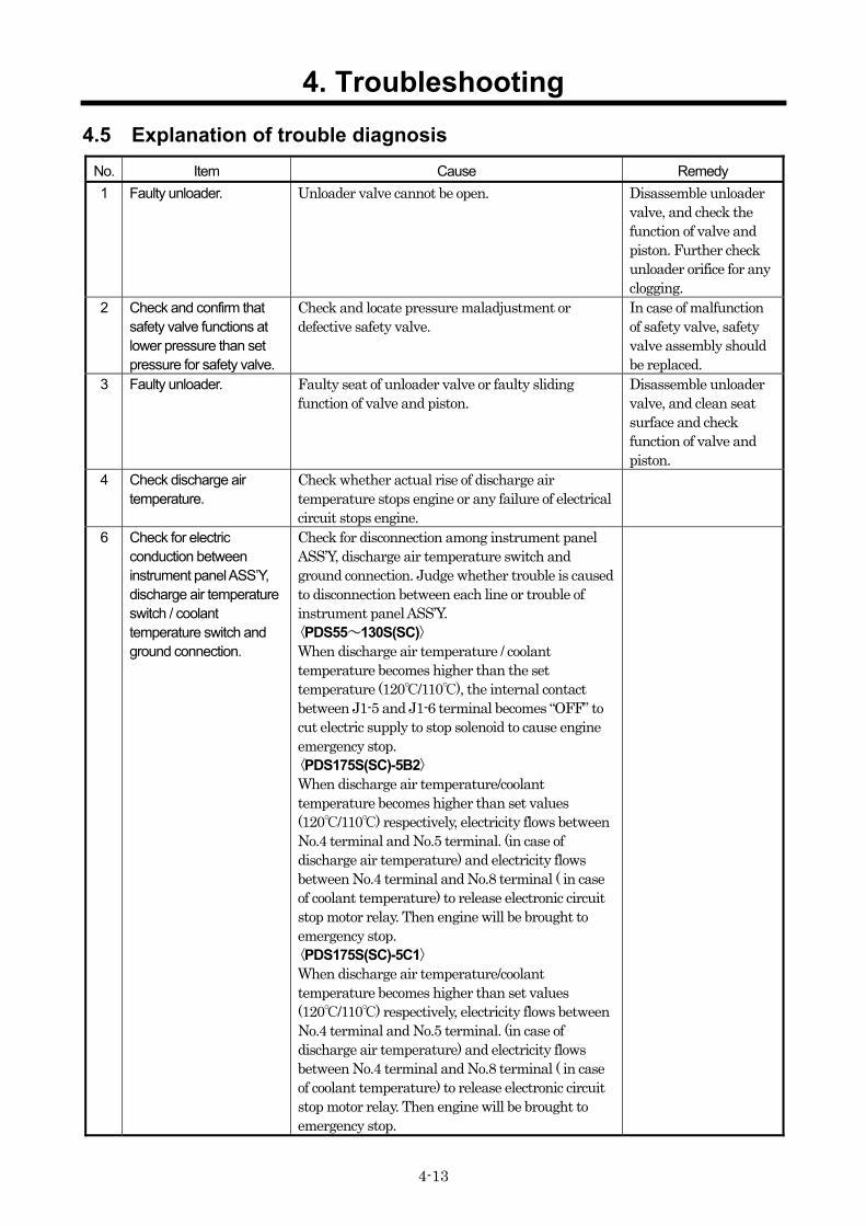
4. Troubleshooting
4-13
4.5 Explanation of trouble diagnosis No. Item Cause Remedy 1 Faulty unloader. Unloader valve cannot be open. Disassemble unloader
valve, and check the function of valve and piston. Further check unloader orifice for any clogging.
2 Check and confirm that safety valve functions at lower pressure than set pressure for safety valve.
Check and locate pressure maladjustment or defective safety valve.
In case of malfunction of safety valve, safety valve assembly should be replaced.
3 Faulty unloader. Faulty seat of unloader valve or faulty sliding function of valve and piston.
Disassemble unloader valve, and clean seat surface and check function of valve and piston.
4 Check discharge air temperature.
Check whether actual rise of discharge air temperature stops engine or any failure of electrical circuit stops engine.
6 Check for electric conduction between instrument panel ASS’Y, discharge air temperature switch / coolant temperature switch and ground connection.
Check for disconnection among instrument panel ASS’Y, discharge air temperature switch and ground connection. Judge whether trouble is caused to disconnection between each line or trouble of instrument panel ASS’Y. 〈PDS55~130S(SC)〉 When discharge air temperature / coolant temperature becomes higher than the set temperature (120/110), the internal contact between J1-5 and J1-6 terminal becomes “OFF” to cut electric supply to stop solenoid to cause engine emergency stop. 〈PDS175S(SC)-5B2〉
When discharge air temperature/coolant temperature becomes higher than set values (120/110) respectively, electricity flows between No.4 terminal and No.5 terminal. (in case of discharge air temperature) and electricity flows between No.4 terminal and No.8 terminal ( in case of coolant temperature) to release electronic circuit stop motor relay. Then engine will be brought to emergency stop. 〈PDS175S(SC)-5C1〉
When discharge air temperature/coolant temperature becomes higher than set values (120/110) respectively, electricity flows between No.4 terminal and No.5 terminal. (in case of discharge air temperature) and electricity flows between No.4 terminal and No.8 terminal ( in case of coolant temperature) to release electronic circuit stop motor relay. Then engine will be brought to emergency stop.

4. Troubleshooting
4-14
No. Item Cause Remedy 8 Check engine oil pressure
switch. For actuation pressure of oil pressure switch, See 1.2 “List of set values”.
9 Check for any defective connection.
Check and make sure that no disconnection has been found for engine oil pressure switch (Switching “OFF” engine oil pressure switch enables engine emergency stop.)
10 Faulty of engine cooling system.
When any trouble is not found in thermostat, coolant pump can be in disorder.
For the temperature at which thermostat valve opens, refer to 2.6.
11 Check warning lamp wire connection.
It sometimes happens that emergency stop circuit is active, but warning lamp will not light on because its circuit is in trouble. Try to locate its cause.
12 Check function of internal contact between instrument panel ASS’Y J1-5 and J1-6.
During normal operation, internal contact between J1-5 and J1-6 terminal instrument panel ASS’Y becomes “ON” and when it is “OFF”, it causes emergency stop.

5. References
5-1
5.1 Comparison between consumable parts and electrical appliances PDS55S-5B2/5C1, PDS75,100S[SC]-5B2/5C1, PDS130S[SC]-5B2
Item PDS55S-5B2 <PDS55S-5C1>
PDS75S[SC]-5B2 PDS75S[SC]-5C1
PDS100S[SC]-5B2 <PDS100S[SC]-5C1> PDS130S[SC]-5B2
Element
Air filter ASS’Y 32100 40500 32100 38701 32100 38701 <32100 40900> 32100 40900
Air filter element 32143 11500 32143 11700 32143 11700 <32143 11800> 32143 11800
Oil Separator 34220 15900 34220 12301 ← 34220 13001
Gasket (O-ring) Gasket: 03737 16802×2 ← ← O-ring:
03402 15140 Compressor oil filter ASS'Y 37400 10600 37400 12700 ← 37400 13000
Oil filter cartridge 37438 02300 37438 05300 ← 37438 05201
Engine oil filter element SHIBAURA: 140517030
SHIBAURA: 140517020
← ←
Fuel filter element SHIBAURA: 360720020
SHIBAURA: 360720060
← ←
O-ring (Small) SHIBAURA: 052100100 - - -
O-ring (Big) SHIBAURA: 052100400
SHIBAURA: 052100440 ← ←
Sedimenter element - SHIBAURA: 130366110 ← ←
O-ring - SHIBAURA: 052100440 ← ←
Air control Speed regulator ASS'Y 36400 18901 ← ← ← Diaphragm 36437 01500 ← ← ← Pressure regulator ASS'Y 36400 19000 ← ← ←
Auto relief valve ASS'Y 36600 03501 ← ← ← Needle valve 36429 00800 ← ← ← O-ring (Small) 03402 25008 ← ← ← O-ring (Medium) 03402 25021 ← ← ← O-ring (Big) 21221 02100 ← ← ← Unloader valve ASS'Y 22100 40100 22100 37303 ← ← Bushing 23124 08700 23124 14400 ← ← O-ring (Big) 03402 15095 - - - O-ring (Medium) 21441 03700 21441 03000 ← ← O-ring (Small-1) 03402 25009 - - - O-ring (Small-2) - - - - Pressure control valve ASS'Y - -
(Pressure control orifice) ← ←
O-ring (Big) 03402 25042 - - - O-ring (Small) 03402 20020 - - - Spring 22144 09900 - - - Piston 35303 03001 - - -

5. References
5-2
Item PDS55S-5B2 <PDS55S-5C1>
PDS75S[SC]-5B2 PDS75S[SC]-5C1
PDS100S[SC]-5B2 <PDS100S[SC]-5C1> PDS130S[SC]-5B2
Instruments on panel Starter switch 44322 07200 ← ← ← Pressure gauge 36141 15503 ← ← ← Electrical appliances Instrument panel ASS’Y 36100 07200 ← ← ←
Glow controller 44346 12500
(SHIBAURA: 385870960)
← ← ←
Coolant temp. sensor (for glow) 44334 14800 ← ← ←
Glow relay 44346 14800 ← ← ← Starter relay 44346 12700 ← ← ← Solenoid relay (Stop motor relay)
44346 06300 <44346 15800> ← ← 44346 06300
Stop relay (a) - - - - Stop relay (b) - - - -
Dynamo regulator 44323 06600
(SHIBAURA: 185516170)
← ← 44323 06900
(SHIBAURA: 185516180)
Fuel air bleeding solenoid pump
43650 01500 (SHIBAURA:
130506240) ← ← ←
Sending unit 36159 02101 36159 03000 ← 36159 02202 Fuse (10A) 46934 03200 ← ← ← Discharge air temp. switch 44334 16500 ← ← ←
Coolant temp. switch 44334 17500 ← ← ←
Engine oil pressure switch
44328 06700 (SHIBAURA:
185246160) ← ← ←
Fuse (20A) - - - - Fuse (1A) - - - - Fuse (5A) - - - - Charge relay - - - - Fuel drain relay - - - -

5. References
5-3
PDS175S[SC]-5B2/5C1
Item PDS175S[SC]-5B2 PDS175S[SC]-5C1
Element Air filter ASS’Y 32100 41001 ←
Air filter element 32143 12700 ←
Oil Separator 34220 13001 ←
Gasket (O-ring) O-ring: 03402 15140 ←
Compressor oil filter ASS'Y 37400 12900 ←
Oil filter cartridge 37438 05201 ←
Engine oil filter element NISSAN DIESEL :1520843G0A ←
Fuel filter element NISSAN DIESEL :16403J5500 43543 01100
O-ring (Small) - - O-ring (Big) - -
Sedimenter element NISSAN DIESEL :1640095006
-
O-ring - - Air control Speed regulator ASS'Y 36400 19200 36400 22300 Diaphragm 36437 01500 ← Pressure regulator ASS'Y 36400 19000 ←
Auto relief valve ASS'Y 36600 03501 - Needle valve 36429 00800 ← O-ring (Small) 03402 25008 ← O-ring (Medium) 03402 25021 ← O-ring (Big) 21221 02100 ← Unloader valve ASS'Y 22100 37303 22100 40301 Bushing 23124 14400 23124 15600 O-ring (Big) - 03402 10125 O-ring (Medium) 21441 03000 03402 10125 O-ring (Small-1) - 21441 04800 O-ring (Small-2) - 21441 04900 Pressure control valve ASS'Y
- (Pressure control orifice) 35307 16102
O-ring (Big) - 03402 20036 O-ring (Small) - - Spring - 35304 02500 Piston - 35303 04800

5. References
5-4
Item PDS175S[SC]-5B2 PDS175S[SC]-5C1
Instruments on panel Starter switch 44322 07200 ← Pressure gauge 36100 06700 ← Electrical appliances Instrument panel ASS’Y 36100 06700 ← Glow controller 44327 04100 ← Coolant temp. sensor (for glow)
NISSAN DIESEL :22630-10G00 ←
Glow relay 44346 07200 ← Starter relay 44324 05400 ← Solenoid relay (Stop motor relay) 44346 07300 -
Stop relay (a) - 44346 08400 Stop relay (b) - 44346 07300 Dynamo regulator - - Fuel air bleeding solenoid pump 43650 01900 -
Sending unit 36159 02202 ← Fuse (10A) - 46934 03200 Discharge air temp. switch 44334 16500 ←
Coolant temp. switch 44334 09300 ← Engine oil pressure switch 44328 07900 44328 19100
Fuse (20A) - - Fuse (1A) 46934 04500 ← Fuse (5A) - 46934 05000 Charge relay - 44346 08400 Fuel drain relay - 44346 07300

5-5
5.2 Engine Wiring Diagram (1)PDS55S-5B2, PDS75,100S[SC]-5B2 [Engine Wiring Diagram]
PC08073E
PDS55S-5B2 PDS75,100S[SC]-5B2

5-6
(2) PDS55S-5B2, PDS75,100S[SC]-5B2 [Sequence]
PC08072E
PDS55S-5B2 PDS75,100S[SC]-5B2

5-7
(3)PDS55S-5C1, PDS75,100S[SC]-5C1 [Engine Wiring Diagram]
PC08075E

5-8
(4)PDS55S-5C1, PDS75,100S[SC]-5C1 [Sequence]
PC08074E

5-9
(5)PDS130S[SC]-5B2 [Engine Wiring Diagram]
PC09014E

5-10
(6)PDS130S[SC]-5B2 [Sequence]
PC08076E

5-11
(7)PDS175S[SC]-5B2 [Engine Wiring Diagram]
PC09011E

5-12
(8)PDS175S[SC]-5B2 [Sequence]
PC09012E
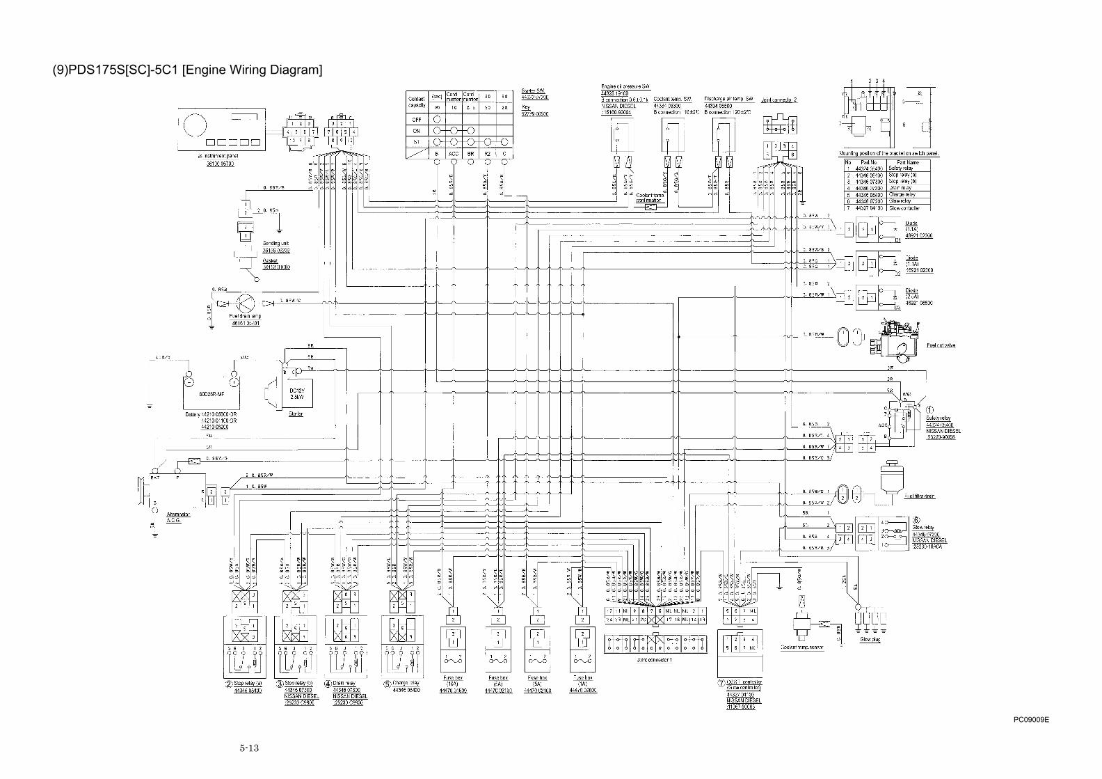
5-13
(9)PDS175S[SC]-5C1 [Engine Wiring Diagram]
PC09009E

5-14
(10)PDS175S[SC]-5C1 [Sequence]
PC09010E

NPC-0054-1PRINTED IN JAPAN 2010. 1
Copyright(C)2010 HOKUETSU INDUSTRIES CO., LTD. All Rights Reserved.
HOKUETSU INDUSTRIES CO., LTD.
8TH FLOOR SHINJUKU SAN-EI BLDG, 22-2 NISHI-SHINJUKU 1-CHOME,SHINJUKU-KU TOKYO 160-0023 JAPAN TEL:81-3-3348-7281 FAX:81-3-3348-7289 URL:http//www.airman.co.jp
2006年 2月 27日 初版
2003年 4月 20日 改訂
発行 北 越 工 業 株 式 会 社
新潟県燕市下粟生津3074
TEL 0256-93-5571
FAX 0256-94-7567
(無断複写・転載を禁ず)
本社工場
This text book contains the most recent information available at the time ofprinting, and the contents of the list are based on information in effect at thattime and are subject to change without notice.