Medium Voltage Metal Enclosed Thyristor Switched … · These less costly stages use standard...
8
Medium Voltage Metal Enclosed Thyristor Switched Harmonic Filter Banks Product Selection & Application Guide Product Description GE's Thyristor Switched Harmonic Filter Banks (TSC), are custom designed for power systems requiring instantane- ous var support to mitigate voltage sags, voltage flicker, and high inrush currents associated with large dynamic loads and motor starting. The TSC samples your phase voltage, load, and line currents at rates exceeding 7,000 times a second, analyzes them in real-time, and instantly changes state to match your load requirements. Adjusting 60 times a second on each phase, the TSC effectively stiffens your supply voltage. Industries with large dynamic loads like pump stations, welders, shredders, rolling mills, and arc furnaces benefit from this product and have seen paybacks in less than 1 year with improved voltage stability, plant productivity, and power factor improvement.
Transcript of Medium Voltage Metal Enclosed Thyristor Switched … · These less costly stages use standard...
Medium Voltage Metal Enclosed Thyristor Switched Harmonic Filter Banks
Product Selection & Application Guide
Product Description
GE's Thyristor Switched Harmonic Filter Banks (TSC), are custom designed for power systems requiring instantane-
ous var support to mitigate voltage sags, voltage flicker, and high inrush currents associated with large dynamic
loads and motor starting.
The TSC samples your phase voltage, load, and line currents at rates exceeding 7,000 times a second, analyzes
them in real-time, and instantly changes state to match your load requirements. Adjusting 60 times a second on
each phase, the TSC effectively stiffens your supply voltage.
Industries with large dynamic loads like pump stations, welders, shredders, rolling mills, and arc furnaces benefit
from this product and have seen paybacks in less than 1 year with improved voltage stability, plant productivity,
and power factor improvement.
2 GEGridSolutions.com
APPLICATION AND SELECTION GUIDE
THYRISTOR SWITCHED HARMONIC FILTER BANKS
Product Scope
Operating Voltage: 2.4kV through 24.9kV
Impulse Withstand Voltage: 60kV BIL - 125kV BIL
Reactive power rating: 0.5 MVAR to 100 MVAR
(binary step design, 1 to 15 steps)
Filter Type(s): Notch (Band Pass), High-Pass, Multi-tuned
Metal-Enclosed: NEMA 1, 3R, 4X, 12 | IEC IP10, IP14, IP56, IP52
Comes fully assembled, tested, and ready for inter-connection
Integral air-disconnect /ground switch, fixed or draw-out circuit breaker
Integral protection and control system
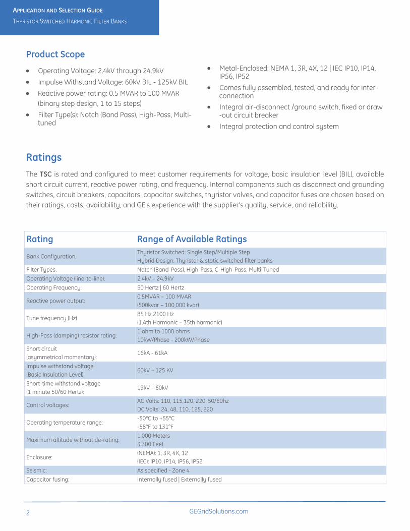
Ratings
The TSC is rated and configured to meet customer requirements for voltage, basic insulation level (BIL), available
short circuit current, reactive power rating, and frequency. Internal components such as disconnect and grounding
switches, circuit breakers, capacitors, capacitor switches, thyristor valves, and capacitor fuses are chosen based on
their ratings, costs, availability, and GE's experience with the supplier's quality, service, and reliability.
Rating Range of Available Ratings
Bank Configuration: Thyristor Switched: Single Step/Multiple Step
Hybrid Design: Thyristor & static switched filter banks
Filter Types: Notch (Band-Pass), High-Pass, C-High-Pass, Multi-Tuned
Operating Voltage (line-to-line): 2.4kV – 24.9kV
Operating Frequency: 50 Hertz | 60 Hertz
Reactive power output: 0.5MVAR – 100 MVAR
(500kvar – 100,000 kvar)
Tune frequency (Hz) 85 Hz 2100 Hz
(1.4th Harmonic – 35th harmonic)
High-Pass (damping) resistor rating: 1 ohm to 1000 ohms
10kW/Phase - 200kW/Phase
Short circuit
(asymmetrical momentary): 16kA - 61kA
Impulse withstand voltage
(Basic Insulation Level): 60kV – 125 KV
Short-time withstand voltage
(1 minute 50/60 Hertz): 19kV – 60kV
Control voltages: AC Volts: 110, 115,120, 220, 50/60hz
DC Volts: 24, 48, 110, 125, 220
Operating temperature range: -50°C to +55°C
-58°F to 131°F
Maximum altitude without de-rating: 1,000 Meters
3,300 Feet
Enclosure: (NEMA): 1, 3R, 4X, 12
(IEC): IP10, IP14, IP56, IP52
Seismic: As specified - Zone 4
Capacitor fusing: Internally fused | Externally fused

GEGridSolutions.com
3
APPLICATION AND SELECTION GUIDE
THYRISTOR SWITCHED HARMONIC FILTER BANKS
Equipment Configuration
GE’s TSC’s are custom designed, configured, and rated to mitigate site-specific voltage sags, flicker, harmonic
distortion and system power factor. Depending upon the performance objectives, the TSC may also include
conventionally switched filter stages. These less costly stages use standard capacitor switches to provide "slow
VARs" for power factor correction and harmonic attenuation, reserving the Thyristor-switched stages to provide
"fast VARs" for mitigating voltage sags and voltage flicker.
Sections 1, 2, and 3 that follow provide details on some of the available options.
The incoming compartment of the TSC is available with a range of options based on system ratings and customer preference.
Typical configurations include some of the following:
Incoming Compartment Configuration Options
Accessories For Incoming Compartment
4 GEGridSolutions.com
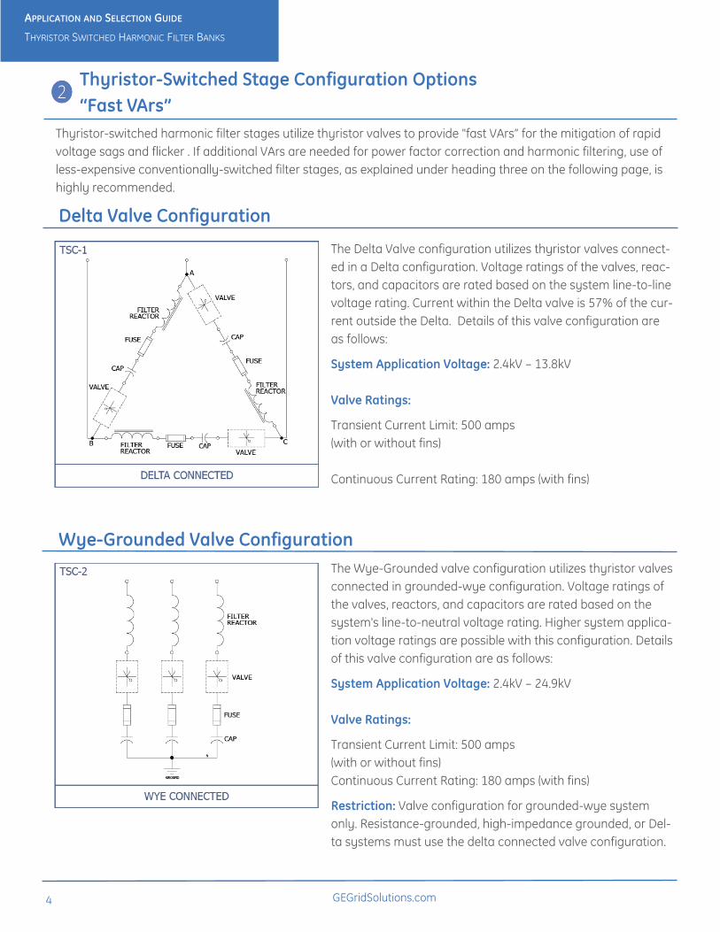
Thyristor-Switched Stage Configuration Options
“Fast VArs”
Thyristor-switched harmonic filter stages utilize thyristor valves to provide "fast VArs” for the mitigation of rapid
voltage sags and flicker . If additional VArs are needed for power factor correction and harmonic filtering, use of
less-expensive conventionally-switched filter stages, as explained under heading three on the following page, is
highly recommended.
The Delta Valve configuration utilizes thyristor valves connect-
ed in a Delta configuration. Voltage ratings of the valves, reac-
tors, and capacitors are rated based on the system line-to-line
voltage rating. Current within the Delta valve is 57% of the cur-
rent outside the Delta. Details of this valve configuration are
as follows:
System Application Voltage: 2.4kV – 13.8kV
Valve Ratings:
Transient Current Limit: 500 amps
(with or without fins)
Continuous Current Rating: 180 amps (with fins)
Delta Valve Configuration
The Wye-Grounded valve configuration utilizes thyristor valves
connected in grounded-wye configuration. Voltage ratings of
the valves, reactors, and capacitors are rated based on the
system's line-to-neutral voltage rating. Higher system applica-
tion voltage ratings are possible with this configuration. Details
of this valve configuration are as follows:
System Application Voltage: 2.4kV – 24.9kV
Valve Ratings:
Transient Current Limit: 500 amps
(with or without fins)
Continuous Current Rating: 180 amps (with fins)
Restriction: Valve configuration for grounded-wye system
only. Resistance-grounded, high-impedance grounded, or Del-
ta systems must use the delta connected valve configuration.
Wye-Grounded Valve Configuration
APPLICATION AND SELECTION GUIDE
THYRISTOR SWITCHED HARMONIC FILTER BANKS
GEGridSolutions.com
5
Application and Selection Guide
Thyristor Switched Harmonic Filter Banks
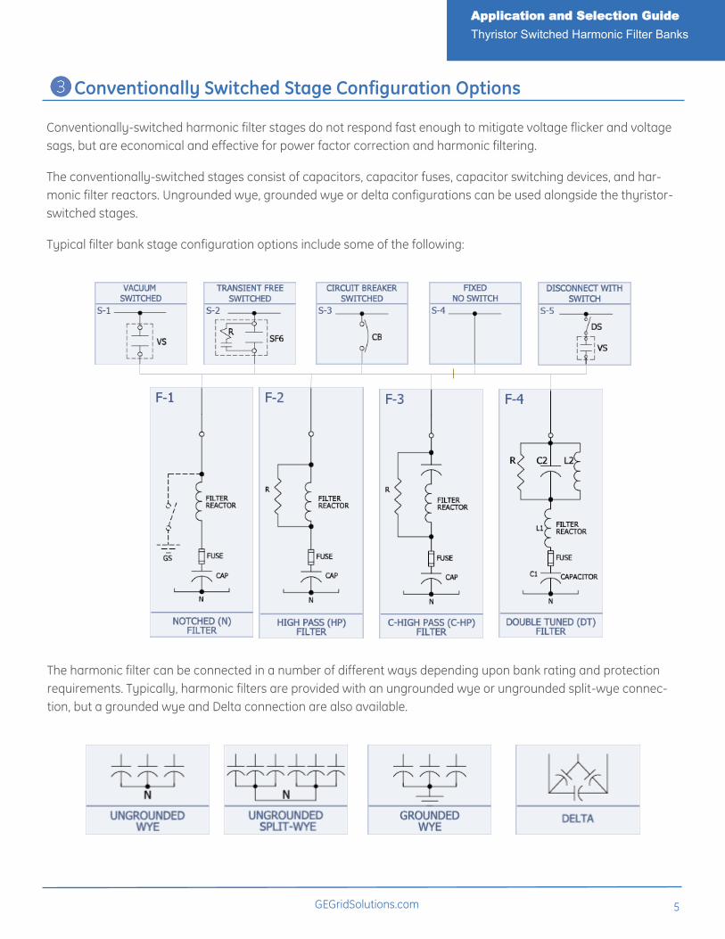
Conventionally Switched Stage Configuration Options
Conventionally-switched harmonic filter stages do not respond fast enough to mitigate voltage flicker and voltage
sags, but are economical and effective for power factor correction and harmonic filtering.
The conventionally-switched stages consist of capacitors, capacitor fuses, capacitor switching devices, and har-
monic filter reactors. Ungrounded wye, grounded wye or delta configurations can be used alongside the thyristor-
switched stages.
Typical filter bank stage configuration options include some of the following:
The harmonic filter can be connected in a number of different ways depending upon bank rating and protection
requirements. Typically, harmonic filters are provided with an ungrounded wye or ungrounded split-wye connec-
tion, but a grounded wye and Delta connection are also available.
6 GEGridSolutions.com
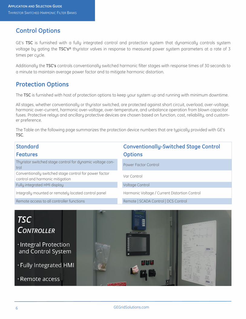
Control Options
GE’s TSC is furnished with a fully integrated control and protection system that dynamically controls system
voltage by gating the TSC’s® thyristor valves in response to measured power system parameters at a rate of 3
times per cycle.
Additionally the TSC’s controls conventionally switched harmonic filter stages with response times of 30 seconds to
a minute to maintain average power factor and to mitigate harmonic distortion.
Standard
Features
Conventionally-Switched Stage Control
Options
Thyristor switched stage control for dynamic voltage con-
trol Power Factor Control
Conventionally switched stage control for power factor
control and harmonic mitigation Var Control
Fully integrated HMI display Voltage Control
Integrally mounted or remotely located control panel Harmonic Voltage / Current Distortion Control
Remote access to all controller functions Remote | SCADA Control | DCS Control
Protection Options
The TSC is furnished with host of protection options to keep your system up and running with minimum downtime.
All stages, whether conventionally or thyristor switched, are protected against short circuit, overload, over-voltage, harmonic over-current, harmonic over-voltage, over-temperature, and unbalance operation from blown capacitor fuses. Protective relays and ancillary protective devices are chosen based on function, cost, reliability, and custom-er preference.
The Table on the following page summarizes the protection device numbers that are typically provided with GE’s TSC.
APPLICATION AND SELECTION GUIDE
THYRISTOR SWITCHED HARMONIC FILTER BANKS
GEGridSolutions.com
7
APPLICATION AND SELECTION GUIDE
THYRISTOR SWITCHED HARMONIC FILTER BANKS
Protection Type Description Designation
Short Circuit and
Overcurrent Protection
Provided by upstream feeder breaker, main incoming breaker (if provided), or
main incoming current limiting fuses (if provided).
50/51
50/51G
Over-Voltage
Protect harmonic filters and power system from over-voltage. Backup to the
SVC and PFC control which use voltage as a primary or secondary control
input.
59
Under-Voltage Under voltage protection system is provided to disconnect the “fast VArs” in
the event of a power interruption or a “fast VArs” control malfunction. 27
Neutral Unbalance
(Blown Fuse Detection)
Relay or direct fuse sensing to detect a capacitor fuse operation. This is critical
since a blown fuse condition will change filter de-tuning, lower var output,
lower performance, and possibly create system resonance.
59N Or 51N or
51G or Direct
Harmonic Voltage &
Current Distortion
Protection against harmonic resonance, high voltage & current distortion, and
harmonic overload ITHD, VTHD
Over-Temperature Protection for the thyristor valves, capacitors, and iron-core reactors. Also
protects against fan failure. 26
Over-Load
Over-load protection of the high-pass resistors (if provided), iron-core reactors,
and thyristor valves. Relay is sensitive to RMS current associated with the fil-
ter's fundamental current and harmonic current.
49
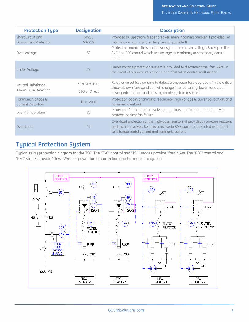
Typical Protection System
Typical relay protection diagram for the TSC. The "TSC" control and "TSC" stages provide "fast" VArs. The "PFC" control and
“PFC” stages provide "slow" VArs for power factor correction and harmonic mitigation.
GE Grid Solutions Capacitor & Power Quality Products (518) 746-5750 381 Broadway, Ft. Edward, NY 128282
GEDigitalEnergy.com
ANSI is a registered trademark of American National Standards Institute, Incorporated.
IEEE is a registered trademark of the Institute of Electrical and Electronic Engineers, Inc.
NEC is a reference to the National Electrical Code part of the National Fire Protection Association.
NESC is the National Electrical Safety Code standard of IEEE.
CSA is part of the Canadian Standards Group.
IEC is a registered trademark of Commission Electrotechnique Internationale.
GE and the GE monogram are trademarks of General Electric Company.
GE reserves the right to make changes to specifications of products described at any time without notice
and without obligation to notify any person of such changes.
Copyright 2014, General Electric Company.