Mechatronic system design · 2 Delft WB2414-Mechatronic System Design 2013-2014 3 University of...
36
1 WB2414-Mechatronic System Design 2013-2014 1 Delft University of Technology Mechatronic system design Mechatronic system design wb2414‐2013/2014 Course part 4 Prof.ir. R.H.Munnig Schmidt Mechatronic System Design Dynamics of motion systems WB2414-Mechatronic System Design 2013-2014 2 Delft University of Technology Contents • Stiffness in Precision Engineering • Passive and active stiffness • Compliance of (a combination of) dynamic elements • Dynamic modelling of damped mass‐spring systems. • Transmissibility • Coupled mass‐spring systems • Eigenmodes, eigenfrequencies and modeshapes • Standard mechanical frequency responses
Transcript of Mechatronic system design · 2 Delft WB2414-Mechatronic System Design 2013-2014 3 University of...

1
WB2414-Mechatronic System Design 2013-2014 1DelftUniversity ofTechnology
Mechatronic system design
Mechatronic system design wb2414‐20132014
Course part 4
Profir RHMunnig SchmidtMechatronic System Design
Dynamics of motion systems
WB2414-Mechatronic System Design 2013-2014 2DelftUniversity ofTechnology
Contents
bull Stiffness in Precision Engineering
bull Passive and active stiffness
bull Compliance of (a combination of) dynamic elements
bull Dynamic modelling of damped mass‐spring systems
bull Transmissibility
bull Coupled mass‐spring systems
bull Eigenmodes eigenfrequencies and modeshapes
bull Standard mechanical frequency responses
2
WB2414-Mechatronic System Design 2013-2014 3DelftUniversity ofTechnology
Well known objects
102 Nm Soft pillow
104 Nm Car suspension
Soft couch
105 Nm Table
Bicycle
107 Nm Office building
108 Nm Concrete pillar
109 Nm Steel train wheel on steel rail track
Stiffness of objects
WB2414-Mechatronic System Design 2013-2014 4DelftUniversity ofTechnology
What is stiffness
s
r
d
d
d
F k x
F F
xk
k
F
x
Hookersquos law for force from spring
Hooke‐Newton law for
external force
Where should you place the stiffness if possible
Take the shortest force loop
3
WB2414-Mechatronic System Design 2013-2014 5DelftUniversity ofTechnology
Natural frequency of the resonance of a mass-spring system
bull At resonance the forces are in
balancebull Deformation force (stiffness) plus acceleration force (mass) is zero
m
k
Stationary reference
x02 2
a d 2 2
d d0
d d
x xF F m kx m kx
t t
0
20 0 0
0
ˆ sin ( t)
ˆ ˆsin( ) sin( )
x x
mx t kx t
k
m
WB2414-Mechatronic System Design 2013-2014 6DelftUniversity ofTechnology
The first natural frequency determines the sensitivity to harmonic vibrations
bullThe maximum force needed to follow the acceleration
bullThe maximum error due to this force
bullThe natural frequency
bullWhich results in
20
k
m
20 0 f f
e f 020 e e
ˆ ˆˆ ˆ
ˆ ˆf x x
x x f ff x x
2f
ˆ ˆ ˆF ma mx
2f
e
ˆ ˆ ˆ
m xFx
k k
4
WB2414-Mechatronic System Design 2013-2014 7DelftUniversity ofTechnology
Active stiffness in a CD player bandwidth
bull200 μm radial vibrations at 25 Hz
bullMass lens 10 10‐3 kg
bullMax radial error 02 μm
6r
0 6r
r0
2r
2 50
ˆ 200 10 25 800
0 2 10
4 =25 Nm 1
middot102
xf f Hz
kf k mf
m
WB2414-Mechatronic System Design 2013-2014 8DelftUniversity ofTechnology
Virtual stiffness
bull Measure position
bull Actuate with force proportional and opposite to the deviation (feedback)
bull Gives virtual spring stiffness
m at rcr pF G G G G G
r tr
Fk G
5
WB2414-Mechatronic System Design 2013-2014 9DelftUniversity ofTechnology
Contents
bull Stiffness in Precision Engineering
bull Passive and active stiffness
bull Compliance of (a combination of) dynamic elements
bull Dynamic modelling of damped mass‐spring systems
bull Transmissibility
bull Coupled mass‐spring systems
bull Eigenmodes eigenfrequencies and modeshapes
bull Standard mechanical frequency responses
WB2414-Mechatronic System Design 2013-2014 10DelftUniversity ofTechnology
10
Stiffness and compliance
bull Stiffness it the ability of a system to withstand a force by
minimising the resulting motiondeformation
bull Compliance is the opposite
bull Both can be real in phase with a periodic force or complex dynamic frequency dependent 90o out of phase with a periodic
force
bull A spring has a real stiffnesscompliance
s
1xC
F k
6
WB2414-Mechatronic System Design 2013-2014 11DelftUniversity ofTechnology
11
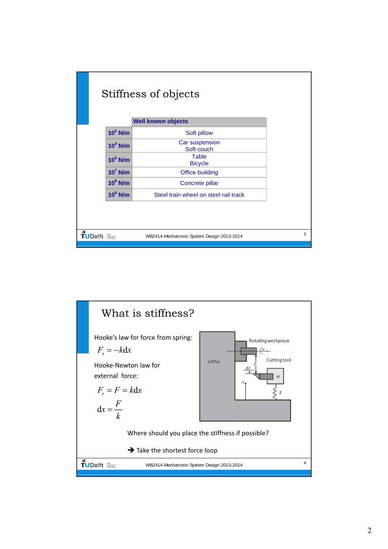
Compliance of (a combination of) dynamic elements
bull k = stiffness of the springbull c = damping coefficient of the damperbull m = mass of the body
m
x0k
Stationary reference
c F
x
s
1xC
F k
WB2414-Mechatronic System Design 2013-2014 12DelftUniversity ofTechnology
Stiffness and compliance of a damper
dd
d( ) ( )
d( )
( )
( )
1 1( )
( )
xF t c F s scx
tF jc x
xC
k F jc
F t
F t
m
x0k
Stationary reference
c F
x
7
WB2414-Mechatronic System Design 2013-2014 13DelftUniversity ofTechnology
Stiffness and compliance of a body
22
2
2
m 2m
( )d
( ) ( )d
( )
1 1( )
(
( )
)
xF t m F s ms x
t
F m x
xC
k F
F t
F t
m
m
x0k
Stationary reference
c F
x
WB2414-Mechatronic System Design 2013-2014 14DelftUniversity ofTechnology
Combined Compliance of body spring and damper
sts d m t
tt
s d m
d m
1 1 1( ) ( ) ( )
1( ) ( )
1 1 1
xF F x
C C C C
xC
FC
F
C C
F
8
WB2414-Mechatronic System Design 2013-2014 15DelftUniversity ofTechnology
Overview of the dynamic properties
WB2414-Mechatronic System Design 2013-2014 16DelftUniversity ofTechnology
The separate element responses in a bode plot
Log |xF|
Log ω
Spring line
Mass line (‐2)
Damper line (‐1)Spring line
Damper line
180 Mass line
1s
s
xC
F k
2
1m
m
xC
F m
1d
d
xC
F c
Phase
90
0
180
0
ω0
020
1 1
k
k m m
9
WB2414-Mechatronic System Design 2013-2014 17DelftUniversity ofTechnology
No dampingDue to energy conservation response becomes infinite(resonance)
Log |xF|
Log ωω0
Phase
180
0
WB2414-Mechatronic System Design 2013-2014 18DelftUniversity ofTechnology
Low damping
180
0
Log |xF|
Log ωω0
Phase
10
WB2414-Mechatronic System Design 2013-2014 19DelftUniversity ofTechnology
High damping
180
0
Log |xF|
Log ωω0
Phase
WB2414-Mechatronic System Design 2013-2014 20DelftUniversity ofTechnology
Extreme damping two first order systems
180
0
Log |xF|
Log ωω0
Phase
11
WB2414-Mechatronic System Design 2013-2014 21DelftUniversity ofTechnology
Contents
bull Stiffness in Precision Engineering
bull Passive and active stiffness
bull Compliance of (a combination of) dynamic elements
bull Dynamic modelling of damped mass‐spring systems
bull Transmissibility
bull Coupled mass‐spring systems
bull Eigenmodes eigenfrequencies and modeshapes
bull Standard mechanical frequency responses
WB2414-Mechatronic System Design 2013-2014 22DelftUniversity ofTechnology
Start with second law of NewtonF=ma
2
2
d d( ) )
d d
x xF t m c kx
t t
2 ( )( ) ( )F s x m ct s sF k
t 2
20 0
( )( ) ( )2 1
sCxC F
s sFt
1sC
k 0
k
m
2
c
km
t 22
11
( ) ( )1
mx kC s sm csF ms cs k sk k
FRF
With only positive imaginary terms (Fourier)
m
x0k
Stationary reference
c F
x
Laplace gives
12
WB2414-Mechatronic System Design 2013-2014 23DelftUniversity ofTechnology
The magnitude and the phase
Start with s=jω
2 22
20 0
( )
1 2
st
CC
And phase angle φ is ndash arctan (imaginaryreal of the denominator)
WB2414-Mechatronic System Design 2013-2014 24DelftUniversity ofTechnology
Compliance Bode plot with damping
m
x0k
Stationary reference
c F
x
bull k = 104 Nm
bull m = 025 kg
13
WB2414-Mechatronic System Design 2013-2014 25DelftUniversity ofTechnology
The damping ratio is related to the pole location in the Laplace plane
s j Poles are those values of s where denominator of Ct is zero
2t
s2
20 0
1
1 2 1
Cx kCm cs s sF sk k
1 2 and d dp j p j
0s
t 1 02
2
If 0 then 0 no damping
and and 1
c
CC p j p j
ms
k
Re
Im
WB2414-Mechatronic System Design 2013-2014 26DelftUniversity ofTechnology
Critical damping ratio
Re
Im
= 1
lt 1
lt 1
gt 1
gt 1
1
2t
s2
20 0
1
1 2 1
Cx kCm cs s sF sk k
1 2 and d dp j p j
s
2
s s2 2t
2
If 2 then 1 and
1
11 2 1 1
c km
C C CkCm cs m m sms s s sk k k k k
14
WB2414-Mechatronic System Design 2013-2014 27DelftUniversity ofTechnology
Above critical damping the mass-spring system reduces to two first order systems
Log |xF|
Log ω
Spring line
Mass line (‐2)
Damper line (‐1)Spring line
Damper line
180 Mass line
1s
s
xC
F k
2
1m
m
xC
F m
1d
d
xC
F c
Phase
90
0
180
0
ω0
020
1 1
k
k m m
WB2414-Mechatronic System Design 2013-2014 28DelftUniversity ofTechnology
Effect of the damping ratio on the stepresponse
At ζ = 1 no overshootCritical dampingtime domain related term
15
WB2414-Mechatronic System Design 2013-2014 29DelftUniversity ofTechnology
Energy at natural Frequency
Energy will be ldquotrappedrdquo in the systemWhen excited in this frequency the amplitude will continue to rise
For electrical engineering (frequency domain) the quality factor Q is defined for this property as resonators are also useful But in mechanical engineering the time domain related term ldquodamping ratiordquo is more commonly used
Letrsquos bridge the gap
WB2414-Mechatronic System Design 2013-2014 30DelftUniversity ofTechnology
Q=100 means peak level at 100 times spring-line level
bull k = 104 Nm
bull m = 025 kg
m
x0k
Stationary reference
c F
x
At Q = 1 no resonance peakfrequency domain related term
16
WB2414-Mechatronic System Design 2013-2014 31DelftUniversity ofTechnology
Relation Q and
1 1
2 2Q
Q
1 1
2 2EE ME
ME EE
Electrical vs mechanical Time vs frequency domain
WB2414-Mechatronic System Design 2013-2014 32DelftUniversity ofTechnology
Velocity response kinetic energy
2
20 0
dd
2 1
s
xv sxtF F F
s C
s s
m
x0k
Stationary reference
c F
x
bull k = 104 Nm
bull m = 025 kg
17
WB2414-Mechatronic System Design 2013-2014 33DelftUniversity ofTechnology
Resonance is energy storage damping is velocity related
bull Driving force is in phase with velocity at resonance
bull Power is Force times speed
bull Max energy transfer at resonance
bull Damper is just the opposite
bull Q tells something about the height of the resonance peak
Maximum energy stored2
Energy lost per cycleQ
WB2414-Mechatronic System Design 2013-2014 34DelftUniversity ofTechnology
Q and energy
18
WB2414-Mechatronic System Design 2013-2014 35DelftUniversity ofTechnology
Contents
bull Stiffness in Precision Engineering
bull Passive and active stiffness
bull Compliance of (a combination of) dynamic elements
bull Dynamic modelling of damped mass‐spring systems
bull Transmissibility
bull Coupled mass‐spring systems
bull Eigenmodes eigenfrequencies and modeshapes
bull Standard mechanical frequency responses
WB2414-Mechatronic System Design 2013-2014 36DelftUniversity ofTechnology
Transmissibility transfer of motion through the support of a dynamic system
2m f m
tm f m2
d d( )( ) ( )
d d
x x xF t m c k x x
t t
02
20 0
2 1
2 1
m
f
sx
s sx
0
k
m
2
c
km
22
1
1
m
f
csx cs k k
m csx ms cs k sk k
With
The force acting on the body equals
m xm
kxfTable
c
Stationary reference
2m f( ) ( )x ms cs k x cs k
19
WB2414-Mechatronic System Design 2013-2014 37DelftUniversity ofTechnology
Bode plot of transmissibility
WB2414-Mechatronic System Design 2013-2014 38DelftUniversity ofTechnology
Contents
bull Stiffness in Precision Engineering
bull Passive and active stiffness
bull Compliance of (a combination of) dynamic elements
bull Dynamic modelling of damped mass‐spring systems
bull Transmissibility
bull Coupled mass‐spring systems
bull Eigenmodes eigenfrequencies and modeshapes
bull Standard mechanical frequency responses
20
WB2414-Mechatronic System Design 2013-2014 39DelftUniversity ofTechnology
Coupled mass-spring systems
m1
x1
km2
x2
F
Stationary reference
Elastically coupled Multi-body or finite-element non-rigid body dynamics
WB2414-Mechatronic System Design 2013-2014 40DelftUniversity ofTechnology
Which statement is true There is a frequency where
m1
x1
km2
x2
F
Stationary reference
1 Only m1 will resonate with k
2 Only m2 will resonate with k
3 Only m1 will stop moving
4 Only m2 will stop moving
21
WB2414-Mechatronic System Design 2013-2014 41DelftUniversity ofTechnology
Equations of Motion
bull First body
bull Second body
m1
x1
km2
x2
F
Stationary reference
21
1 1 22
21 1 1 2
22
2 1 22
22 2 1 2
d ( )( ) ( )
d
( ) ( )
d ( )( )
d
( ) ( )
x tm F t k x x
t
m s x s F k x x
x tm k x x
t
m s x s k x x
note The domain (s or t) is only mentioned once
WB2414-Mechatronic System Design 2013-2014 42DelftUniversity ofTechnology
Resulting equations in the Laplace domain
21 2
4 21 2 1 2
24 2
1 2 1 2
( )
( )
x m s ks
F m m s k m m s
x ks
F m m s k m m s
Low values of s at low frequencies
1 2
21 2
1( ) ( )
x xs s
F F m m s
High values of s at high frequencies
1 22 4
1 1 2
1( ) ( )
x x ks s
F m s F m m s
Fourth order system
22
WB2414-Mechatronic System Design 2013-2014 43DelftUniversity ofTechnology
At mid frequency the driven body shows a strange effect
Combination of poles and zeros
21 2
4 21 2 1 2
24 2
1 2 1 2
2 2
2
1
( )
w
then the compliance of shows a dip
hen
k
m
x m s k
F m m s k m m s
x ks
F m m s k m
s
x
m s
WB2414-Mechatronic System Design 2013-2014 44DelftUniversity ofTechnology
m1 = 01 m2 an actuated large mass by a lighter actuator
1
2
4
3
3
25 10 kg
25 10
1
kg
Nm0
m
m
k
21 2
4 21 2 1 2
24 2
1 2 1 2
( )
( )
x m s ks
F m m s k m m s
x ks
F m m s k m m s
1 2
21 2
1LF ( ) ( )
x x
s sF F m m s
1 22 4
1 1 2
1HF ( ) ( )
x x ks s
F m s F m m s
23
WB2414-Mechatronic System Design 2013-2014 45DelftUniversity ofTechnology
m1 = m2 motor mass is optimisedto the driven mass
31
32
4
25 10 kg
25 10
10
kg
Nm
m
m
k
21 2
4 21 2 1 2
24 2
1 2 1 2
( )
( )
x m s ks
F m m s k m m s
x ks
F m m s k m m s
WB2414-Mechatronic System Design 2013-2014 46DelftUniversity ofTechnology
m1 = 10 m2 parasitic resonances
1
2
4
3
025 kg
25 10 kg
1 m0 N
m
m
k
21 2
4 21 2 1 2
24 2
1 2 1 2
( )
( )
x m s ks
F m m s k m m s
x ks
F m m s k m m s
24
WB2414-Mechatronic System Design 2013-2014 47DelftUniversity ofTechnology
Contents
bull Stiffness in Precision Engineering
bull Passive and active stiffness
bull Compliance of (a combination of) dynamic elements
bull Dynamic modelling of damped mass spring systems
bull Transmissibility
bull Coupled mass spring systems
bull Eigenmodes eigenfrequencies and modeshapes
bull Standard mechanical frequency responses
WB2414-Mechatronic System Design 2013-2014 48DelftUniversity ofTechnology
Eigenmodes
When excited non‐rigid bodies and complex mass‐spring systems
vibrate in different eigenmodes with two main properties
bull Eigenfrequency the related natural (resonance) frequency
bull Mode‐shape the deformation that corresponds with the eigenmode described in a multiple degree of freedom ldquoshape‐
function rdquo
Modelling is done by discretisation of the system in multiple mass‐
spring systems
bull The shape function reduces to an eigenvector with one value for
each body for the relative motion magnitude and direction (sign)
25
WB2414-Mechatronic System Design 2013-2014 49DelftUniversity ofTechnology
Mode-shape of complex non-rigid body
WB2414-Mechatronic System Design 2013-2014 50DelftUniversity ofTechnology
Eigenfrequencies of multiple eigenmodes in 6-DOF
26
WB2414-Mechatronic System Design 2013-2014 51DelftUniversity ofTechnology
Eigen modes of coupled bodies
1
1
1
2
1
1
WB2414-Mechatronic System Design 2013-2014 52DelftUniversity ofTechnology
Multiplicative expression shows two resonating eigenfrequencies
c
c
2122 2
1 2
1 2
1 2
22 2
1 2 c
1 1
with
1
xm s k
F m m s m s k
m mm
m m
x k
F m m s m s k
2
1 2 24 2 4 2
1 2 1 2 1 2 1 2
x m s k x k
F m m s k m m s F m m s k m m s
Starting with
11 2
2
00
m m
k
M
27
WB2414-Mechatronic System Design 2013-2014 53DelftUniversity ofTechnology
Additive expression
bull Can be written as a combination of two eigenmodes with modal
mass and stiffness using eigenvector
21 1 222 2
1 2 1c
c 2
22 2
1 2 c
1 1 with
1
x m mm s k m
F m m s m s k m m
x k
F m m s m s k
2 22 2
2 2
c 1 1
1 2 1 212 2 2 2
1 2
1 2 1 222 2 2 2
1 2
2 2
1 2 1 22 2
c 1 1 2 2
1 1=
( )
1 1=
( )
m m
m m m mx
F m m s m s k s s
m m
m m m mx
F m m s m s k s s
m m
1
1
1
2
1
1
i i i
WB2414-Mechatronic System Design 2013-2014 54DelftUniversity ofTechnology
Modes 1 and 2 combined
1 212 2
1 222
22
2
1 1 2 2
1 22
1 12
2 2
1
1
m
m mx
F s s
m
m mx
F s s
m
28
WB2414-Mechatronic System Design 2013-2014 55DelftUniversity ofTechnology
i
Theory on modal decompositionbull General equation of motion (vectormatrix) of finite element system
bull General transfer function
bull In absence of external force
bull Decoupled by eigenvalue problem where is the eigenvector
2
2
20
( ) ( ) ( )
( ) ( ) ( )
( ) ( ) 0
0i i
Mx t Kx t F t
Ms x s Kx s F s
Ms x s Kx s
K M
WB2414-Mechatronic System Design 2013-2014 56DelftUniversity ofTechnology
Modal mass and stiffness orthogonality of eigenmodes
bull Modal mass
bull Modal Stiffness
20
0 ( )
0 ( )
i j
i i i
i j
i i i i i
M i j
M
K i j
K
29
WB2414-Mechatronic System Design 2013-2014 57DelftUniversity ofTechnology
Scaling
bull Length of eigenvector is not defined (only the direction)
bull Three scaling methods are often applied
1 1
2 max 1
3 1
i i i
i
i
i
M
WB2414-Mechatronic System Design 2013-2014 58DelftUniversity ofTechnology
Modal coordinates
bull When qiequals the motion of eigenmode i then the total displacement vector x(t) will be
where qi is called the modal coordinate
bull This gives the following displacement for DOF xk(t)
1 1 2 2 n n
1 1 2 2 n
( ) ( ) ( ) ( )
( ) ( ) ( ) ( )k k k n k
x t q t q t q t
x t q t q t q t
30
WB2414-Mechatronic System Design 2013-2014 59DelftUniversity ofTechnology
Full set of uncoupled equations
1
1 2 n
n
2
( ) ( )
( )
with and ( ) ( )
( )
applied to ( ) ( ) ( )
gives with pre-multiplication with
( ) ( ) ( )
i
x t q t
q t
q t q t
q t
Ms x s Kx s F s
M q t K q t F t
WB2414-Mechatronic System Design 2013-2014 60DelftUniversity ofTechnology
This can be transformed into a combined transfer function
bull The response of DOF by
eigenmode i on force equals
bull The total response equals
2
i
n n 2
1 1
( )
( )
i k i
k i i
i k i
i ik k i ii
xs
F s
x xs
F F s
xkF
31
WB2414-Mechatronic System Design 2013-2014 61DelftUniversity ofTechnology
Graphical representation
bull The modal coordinate is
represented by the angle of the lever or the displacement at distance 1
bull Modal mass and stiffness are connected to the modal
coordinate
bull The eigenvectors determine the
ratio of ldquocontrollabilityrdquo of actuator and ldquoobservabilityrdquo of sensor
2
i
( ) i k i
k i i
xs
F s
WB2414-Mechatronic System Design 2013-2014 62DelftUniversity ofTechnology
Effective modal values
As perceived at the actuator
32
WB2414-Mechatronic System Design 2013-2014 63DelftUniversity ofTechnology
Mass on leafspring two eigenmodes
F
x
F
x
y
x
a Mode shape 1 b Mode shape 2
Stationary reference Stationary reference
WB2414-Mechatronic System Design 2013-2014 64DelftUniversity ofTechnology
Modes 1 and 2 combined by measuring non co-local with the force
‐2 slope with ‐360o
phase is non‐minimum phase system
33
WB2414-Mechatronic System Design 2013-2014 65DelftUniversity ofTechnology
Non-minimum phase step response
WB2414-Mechatronic System Design 2013-2014 66DelftUniversity ofTechnology
Summary of termsbull Eigenvector
bull Vector with terms that represent the relative motion amplitude of each element in the
discretised structure It is the discretised ldquoshape functionrdquo
bull Scaling is at will as long as the scaling is equal for all properties of that eigenmode
bull Modal mass and stiffnessbull relate to the mass and stiffness matrix by double multiplication with the eigenvector
bull Scaling of the eigenvector also scales the modal mass and stiffness (squared)
bull Modal coordinatesbull Represent the motion of the eigenmode at the location of the modal mass and
stiffness
bull It is used to determine the motion of all elements with the eigenvector and as such it
also depends on the chosen scaling
bull Effective modal mass and stiffness
bull Is the modal mass and stiffness as perceived at the actuator position It is calculated
from the modal mass and stiffness by dividing by the corresponding eigenvector term
squared hence the chosen scaling no longer plays a role
i i i i i iM K
34
WB2414-Mechatronic System Design 2013-2014 67DelftUniversity ofTechnology
Mode-shape of complex non-rigid body
WB2414-Mechatronic System Design 2013-2014 68DelftUniversity ofTechnology
Contents
bull Stiffness in Precision Engineering
bull Passive and active stiffness
bull Compliance of (a combination of) dynamic elements
bull Dynamic modelling of damped mass‐spring systems
bull Transmissibility
bull Coupled mass‐spring systems
bull Eigenmodes eigenfrequencies and modeshapes
bull Standard mechanical frequency responses
35
WB2414-Mechatronic System Design 2013-2014 69DelftUniversity ofTechnology
Typical combination of two eigenmodes one rigid and one non-rigid
bullActuated at xa
bullSensed at different locations
WB2414-Mechatronic System Design 2013-2014 70DelftUniversity ofTechnology
Different combinations of two eigenmodes
36
WB2414-Mechatronic System Design 2013-2014 71DelftUniversity ofTechnology
4 types of responses result
WB2414-Mechatronic System Design 2013-2014 72DelftUniversity ofTechnology
Eigenfrequencies of multiple eigenmodes in 6-DOF
2
WB2414-Mechatronic System Design 2013-2014 3DelftUniversity ofTechnology
Well known objects
102 Nm Soft pillow
104 Nm Car suspension
Soft couch
105 Nm Table
Bicycle
107 Nm Office building
108 Nm Concrete pillar
109 Nm Steel train wheel on steel rail track
Stiffness of objects
WB2414-Mechatronic System Design 2013-2014 4DelftUniversity ofTechnology
What is stiffness
s
r
d
d
d
F k x
F F
xk
k
F
x
Hookersquos law for force from spring
Hooke‐Newton law for
external force
Where should you place the stiffness if possible
Take the shortest force loop
3
WB2414-Mechatronic System Design 2013-2014 5DelftUniversity ofTechnology
Natural frequency of the resonance of a mass-spring system
bull At resonance the forces are in
balancebull Deformation force (stiffness) plus acceleration force (mass) is zero
m
k
Stationary reference
x02 2
a d 2 2
d d0
d d
x xF F m kx m kx
t t
0
20 0 0
0
ˆ sin ( t)
ˆ ˆsin( ) sin( )
x x
mx t kx t
k
m
WB2414-Mechatronic System Design 2013-2014 6DelftUniversity ofTechnology
The first natural frequency determines the sensitivity to harmonic vibrations
bullThe maximum force needed to follow the acceleration
bullThe maximum error due to this force
bullThe natural frequency
bullWhich results in
20
k
m
20 0 f f
e f 020 e e
ˆ ˆˆ ˆ
ˆ ˆf x x
x x f ff x x
2f
ˆ ˆ ˆF ma mx
2f
e
ˆ ˆ ˆ
m xFx
k k
4
WB2414-Mechatronic System Design 2013-2014 7DelftUniversity ofTechnology
Active stiffness in a CD player bandwidth
bull200 μm radial vibrations at 25 Hz
bullMass lens 10 10‐3 kg
bullMax radial error 02 μm
6r
0 6r
r0
2r
2 50
ˆ 200 10 25 800
0 2 10
4 =25 Nm 1
middot102
xf f Hz
kf k mf
m
WB2414-Mechatronic System Design 2013-2014 8DelftUniversity ofTechnology
Virtual stiffness
bull Measure position
bull Actuate with force proportional and opposite to the deviation (feedback)
bull Gives virtual spring stiffness
m at rcr pF G G G G G
r tr
Fk G
5
WB2414-Mechatronic System Design 2013-2014 9DelftUniversity ofTechnology
Contents
bull Stiffness in Precision Engineering
bull Passive and active stiffness
bull Compliance of (a combination of) dynamic elements
bull Dynamic modelling of damped mass‐spring systems
bull Transmissibility
bull Coupled mass‐spring systems
bull Eigenmodes eigenfrequencies and modeshapes
bull Standard mechanical frequency responses
WB2414-Mechatronic System Design 2013-2014 10DelftUniversity ofTechnology
10
Stiffness and compliance
bull Stiffness it the ability of a system to withstand a force by
minimising the resulting motiondeformation
bull Compliance is the opposite
bull Both can be real in phase with a periodic force or complex dynamic frequency dependent 90o out of phase with a periodic
force
bull A spring has a real stiffnesscompliance
s
1xC
F k
6
WB2414-Mechatronic System Design 2013-2014 11DelftUniversity ofTechnology
11
Compliance of (a combination of) dynamic elements
bull k = stiffness of the springbull c = damping coefficient of the damperbull m = mass of the body
m
x0k
Stationary reference
c F
x
s
1xC
F k
WB2414-Mechatronic System Design 2013-2014 12DelftUniversity ofTechnology
Stiffness and compliance of a damper
dd
d( ) ( )
d( )
( )
( )
1 1( )
( )
xF t c F s scx
tF jc x
xC
k F jc
F t
F t
m
x0k
Stationary reference
c F
x
7
WB2414-Mechatronic System Design 2013-2014 13DelftUniversity ofTechnology
Stiffness and compliance of a body
22
2
2
m 2m
( )d
( ) ( )d
( )
1 1( )
(
( )
)
xF t m F s ms x
t
F m x
xC
k F
F t
F t
m
m
x0k
Stationary reference
c F
x
WB2414-Mechatronic System Design 2013-2014 14DelftUniversity ofTechnology
Combined Compliance of body spring and damper
sts d m t
tt
s d m
d m
1 1 1( ) ( ) ( )
1( ) ( )
1 1 1
xF F x
C C C C
xC
FC
F
C C
F
8
WB2414-Mechatronic System Design 2013-2014 15DelftUniversity ofTechnology
Overview of the dynamic properties
WB2414-Mechatronic System Design 2013-2014 16DelftUniversity ofTechnology
The separate element responses in a bode plot
Log |xF|
Log ω
Spring line
Mass line (‐2)
Damper line (‐1)Spring line
Damper line
180 Mass line
1s
s
xC
F k
2
1m
m
xC
F m
1d
d
xC
F c
Phase
90
0
180
0
ω0
020
1 1
k
k m m
9
WB2414-Mechatronic System Design 2013-2014 17DelftUniversity ofTechnology
No dampingDue to energy conservation response becomes infinite(resonance)
Log |xF|
Log ωω0
Phase
180
0
WB2414-Mechatronic System Design 2013-2014 18DelftUniversity ofTechnology
Low damping
180
0
Log |xF|
Log ωω0
Phase
10
WB2414-Mechatronic System Design 2013-2014 19DelftUniversity ofTechnology
High damping
180
0
Log |xF|
Log ωω0
Phase
WB2414-Mechatronic System Design 2013-2014 20DelftUniversity ofTechnology
Extreme damping two first order systems
180
0
Log |xF|
Log ωω0
Phase
11
WB2414-Mechatronic System Design 2013-2014 21DelftUniversity ofTechnology
Contents
bull Stiffness in Precision Engineering
bull Passive and active stiffness
bull Compliance of (a combination of) dynamic elements
bull Dynamic modelling of damped mass‐spring systems
bull Transmissibility
bull Coupled mass‐spring systems
bull Eigenmodes eigenfrequencies and modeshapes
bull Standard mechanical frequency responses
WB2414-Mechatronic System Design 2013-2014 22DelftUniversity ofTechnology
Start with second law of NewtonF=ma
2
2
d d( ) )
d d
x xF t m c kx
t t
2 ( )( ) ( )F s x m ct s sF k
t 2
20 0
( )( ) ( )2 1
sCxC F
s sFt
1sC
k 0
k
m
2
c
km
t 22
11
( ) ( )1
mx kC s sm csF ms cs k sk k
FRF
With only positive imaginary terms (Fourier)
m
x0k
Stationary reference
c F
x
Laplace gives
12
WB2414-Mechatronic System Design 2013-2014 23DelftUniversity ofTechnology
The magnitude and the phase
Start with s=jω
2 22
20 0
( )
1 2
st
CC
And phase angle φ is ndash arctan (imaginaryreal of the denominator)
WB2414-Mechatronic System Design 2013-2014 24DelftUniversity ofTechnology
Compliance Bode plot with damping
m
x0k
Stationary reference
c F
x
bull k = 104 Nm
bull m = 025 kg
13
WB2414-Mechatronic System Design 2013-2014 25DelftUniversity ofTechnology
The damping ratio is related to the pole location in the Laplace plane
s j Poles are those values of s where denominator of Ct is zero
2t
s2
20 0
1
1 2 1
Cx kCm cs s sF sk k
1 2 and d dp j p j
0s
t 1 02
2
If 0 then 0 no damping
and and 1
c
CC p j p j
ms
k
Re
Im
WB2414-Mechatronic System Design 2013-2014 26DelftUniversity ofTechnology
Critical damping ratio
Re
Im
= 1
lt 1
lt 1
gt 1
gt 1
1
2t
s2
20 0
1
1 2 1
Cx kCm cs s sF sk k
1 2 and d dp j p j
s
2
s s2 2t
2
If 2 then 1 and
1
11 2 1 1
c km
C C CkCm cs m m sms s s sk k k k k
14
WB2414-Mechatronic System Design 2013-2014 27DelftUniversity ofTechnology
Above critical damping the mass-spring system reduces to two first order systems
Log |xF|
Log ω
Spring line
Mass line (‐2)
Damper line (‐1)Spring line
Damper line
180 Mass line
1s
s
xC
F k
2
1m
m
xC
F m
1d
d
xC
F c
Phase
90
0
180
0
ω0
020
1 1
k
k m m
WB2414-Mechatronic System Design 2013-2014 28DelftUniversity ofTechnology
Effect of the damping ratio on the stepresponse
At ζ = 1 no overshootCritical dampingtime domain related term
15
WB2414-Mechatronic System Design 2013-2014 29DelftUniversity ofTechnology
Energy at natural Frequency
Energy will be ldquotrappedrdquo in the systemWhen excited in this frequency the amplitude will continue to rise
For electrical engineering (frequency domain) the quality factor Q is defined for this property as resonators are also useful But in mechanical engineering the time domain related term ldquodamping ratiordquo is more commonly used
Letrsquos bridge the gap
WB2414-Mechatronic System Design 2013-2014 30DelftUniversity ofTechnology
Q=100 means peak level at 100 times spring-line level
bull k = 104 Nm
bull m = 025 kg
m
x0k
Stationary reference
c F
x
At Q = 1 no resonance peakfrequency domain related term
16
WB2414-Mechatronic System Design 2013-2014 31DelftUniversity ofTechnology
Relation Q and
1 1
2 2Q
Q
1 1
2 2EE ME
ME EE
Electrical vs mechanical Time vs frequency domain
WB2414-Mechatronic System Design 2013-2014 32DelftUniversity ofTechnology
Velocity response kinetic energy
2
20 0
dd
2 1
s
xv sxtF F F
s C
s s
m
x0k
Stationary reference
c F
x
bull k = 104 Nm
bull m = 025 kg
17
WB2414-Mechatronic System Design 2013-2014 33DelftUniversity ofTechnology
Resonance is energy storage damping is velocity related
bull Driving force is in phase with velocity at resonance
bull Power is Force times speed
bull Max energy transfer at resonance
bull Damper is just the opposite
bull Q tells something about the height of the resonance peak
Maximum energy stored2
Energy lost per cycleQ
WB2414-Mechatronic System Design 2013-2014 34DelftUniversity ofTechnology
Q and energy
18
WB2414-Mechatronic System Design 2013-2014 35DelftUniversity ofTechnology
Contents
bull Stiffness in Precision Engineering
bull Passive and active stiffness
bull Compliance of (a combination of) dynamic elements
bull Dynamic modelling of damped mass‐spring systems
bull Transmissibility
bull Coupled mass‐spring systems
bull Eigenmodes eigenfrequencies and modeshapes
bull Standard mechanical frequency responses
WB2414-Mechatronic System Design 2013-2014 36DelftUniversity ofTechnology
Transmissibility transfer of motion through the support of a dynamic system
2m f m
tm f m2
d d( )( ) ( )
d d
x x xF t m c k x x
t t
02
20 0
2 1
2 1
m
f
sx
s sx
0
k
m
2
c
km
22
1
1
m
f
csx cs k k
m csx ms cs k sk k
With
The force acting on the body equals
m xm
kxfTable
c
Stationary reference
2m f( ) ( )x ms cs k x cs k
19
WB2414-Mechatronic System Design 2013-2014 37DelftUniversity ofTechnology
Bode plot of transmissibility
WB2414-Mechatronic System Design 2013-2014 38DelftUniversity ofTechnology
Contents
bull Stiffness in Precision Engineering
bull Passive and active stiffness
bull Compliance of (a combination of) dynamic elements
bull Dynamic modelling of damped mass‐spring systems
bull Transmissibility
bull Coupled mass‐spring systems
bull Eigenmodes eigenfrequencies and modeshapes
bull Standard mechanical frequency responses
20
WB2414-Mechatronic System Design 2013-2014 39DelftUniversity ofTechnology
Coupled mass-spring systems
m1
x1
km2
x2
F
Stationary reference
Elastically coupled Multi-body or finite-element non-rigid body dynamics
WB2414-Mechatronic System Design 2013-2014 40DelftUniversity ofTechnology
Which statement is true There is a frequency where
m1
x1
km2
x2
F
Stationary reference
1 Only m1 will resonate with k
2 Only m2 will resonate with k
3 Only m1 will stop moving
4 Only m2 will stop moving
21
WB2414-Mechatronic System Design 2013-2014 41DelftUniversity ofTechnology
Equations of Motion
bull First body
bull Second body
m1
x1
km2
x2
F
Stationary reference
21
1 1 22
21 1 1 2
22
2 1 22
22 2 1 2
d ( )( ) ( )
d
( ) ( )
d ( )( )
d
( ) ( )
x tm F t k x x
t
m s x s F k x x
x tm k x x
t
m s x s k x x
note The domain (s or t) is only mentioned once
WB2414-Mechatronic System Design 2013-2014 42DelftUniversity ofTechnology
Resulting equations in the Laplace domain
21 2
4 21 2 1 2
24 2
1 2 1 2
( )
( )
x m s ks
F m m s k m m s
x ks
F m m s k m m s
Low values of s at low frequencies
1 2
21 2
1( ) ( )
x xs s
F F m m s
High values of s at high frequencies
1 22 4
1 1 2
1( ) ( )
x x ks s
F m s F m m s
Fourth order system
22
WB2414-Mechatronic System Design 2013-2014 43DelftUniversity ofTechnology
At mid frequency the driven body shows a strange effect
Combination of poles and zeros
21 2
4 21 2 1 2
24 2
1 2 1 2
2 2
2
1
( )
w
then the compliance of shows a dip
hen
k
m
x m s k
F m m s k m m s
x ks
F m m s k m
s
x
m s
WB2414-Mechatronic System Design 2013-2014 44DelftUniversity ofTechnology
m1 = 01 m2 an actuated large mass by a lighter actuator
1
2
4
3
3
25 10 kg
25 10
1
kg
Nm0
m
m
k
21 2
4 21 2 1 2
24 2
1 2 1 2
( )
( )
x m s ks
F m m s k m m s
x ks
F m m s k m m s
1 2
21 2
1LF ( ) ( )
x x
s sF F m m s
1 22 4
1 1 2
1HF ( ) ( )
x x ks s
F m s F m m s
23
WB2414-Mechatronic System Design 2013-2014 45DelftUniversity ofTechnology
m1 = m2 motor mass is optimisedto the driven mass
31
32
4
25 10 kg
25 10
10
kg
Nm
m
m
k
21 2
4 21 2 1 2
24 2
1 2 1 2
( )
( )
x m s ks
F m m s k m m s
x ks
F m m s k m m s
WB2414-Mechatronic System Design 2013-2014 46DelftUniversity ofTechnology
m1 = 10 m2 parasitic resonances
1
2
4
3
025 kg
25 10 kg
1 m0 N
m
m
k
21 2
4 21 2 1 2
24 2
1 2 1 2
( )
( )
x m s ks
F m m s k m m s
x ks
F m m s k m m s
24
WB2414-Mechatronic System Design 2013-2014 47DelftUniversity ofTechnology
Contents
bull Stiffness in Precision Engineering
bull Passive and active stiffness
bull Compliance of (a combination of) dynamic elements
bull Dynamic modelling of damped mass spring systems
bull Transmissibility
bull Coupled mass spring systems
bull Eigenmodes eigenfrequencies and modeshapes
bull Standard mechanical frequency responses
WB2414-Mechatronic System Design 2013-2014 48DelftUniversity ofTechnology
Eigenmodes
When excited non‐rigid bodies and complex mass‐spring systems
vibrate in different eigenmodes with two main properties
bull Eigenfrequency the related natural (resonance) frequency
bull Mode‐shape the deformation that corresponds with the eigenmode described in a multiple degree of freedom ldquoshape‐
function rdquo
Modelling is done by discretisation of the system in multiple mass‐
spring systems
bull The shape function reduces to an eigenvector with one value for
each body for the relative motion magnitude and direction (sign)
25
WB2414-Mechatronic System Design 2013-2014 49DelftUniversity ofTechnology
Mode-shape of complex non-rigid body
WB2414-Mechatronic System Design 2013-2014 50DelftUniversity ofTechnology
Eigenfrequencies of multiple eigenmodes in 6-DOF
26
WB2414-Mechatronic System Design 2013-2014 51DelftUniversity ofTechnology
Eigen modes of coupled bodies
1
1
1
2
1
1
WB2414-Mechatronic System Design 2013-2014 52DelftUniversity ofTechnology
Multiplicative expression shows two resonating eigenfrequencies
c
c
2122 2
1 2
1 2
1 2
22 2
1 2 c
1 1
with
1
xm s k
F m m s m s k
m mm
m m
x k
F m m s m s k
2
1 2 24 2 4 2
1 2 1 2 1 2 1 2
x m s k x k
F m m s k m m s F m m s k m m s
Starting with
11 2
2
00
m m
k
M
27
WB2414-Mechatronic System Design 2013-2014 53DelftUniversity ofTechnology
Additive expression
bull Can be written as a combination of two eigenmodes with modal
mass and stiffness using eigenvector
21 1 222 2
1 2 1c
c 2
22 2
1 2 c
1 1 with
1
x m mm s k m
F m m s m s k m m
x k
F m m s m s k
2 22 2
2 2
c 1 1
1 2 1 212 2 2 2
1 2
1 2 1 222 2 2 2
1 2
2 2
1 2 1 22 2
c 1 1 2 2
1 1=
( )
1 1=
( )
m m
m m m mx
F m m s m s k s s
m m
m m m mx
F m m s m s k s s
m m
1
1
1
2
1
1
i i i
WB2414-Mechatronic System Design 2013-2014 54DelftUniversity ofTechnology
Modes 1 and 2 combined
1 212 2
1 222
22
2
1 1 2 2
1 22
1 12
2 2
1
1
m
m mx
F s s
m
m mx
F s s
m
28
WB2414-Mechatronic System Design 2013-2014 55DelftUniversity ofTechnology
i
Theory on modal decompositionbull General equation of motion (vectormatrix) of finite element system
bull General transfer function
bull In absence of external force
bull Decoupled by eigenvalue problem where is the eigenvector
2
2
20
( ) ( ) ( )
( ) ( ) ( )
( ) ( ) 0
0i i
Mx t Kx t F t
Ms x s Kx s F s
Ms x s Kx s
K M
WB2414-Mechatronic System Design 2013-2014 56DelftUniversity ofTechnology
Modal mass and stiffness orthogonality of eigenmodes
bull Modal mass
bull Modal Stiffness
20
0 ( )
0 ( )
i j
i i i
i j
i i i i i
M i j
M
K i j
K
29
WB2414-Mechatronic System Design 2013-2014 57DelftUniversity ofTechnology
Scaling
bull Length of eigenvector is not defined (only the direction)
bull Three scaling methods are often applied
1 1
2 max 1
3 1
i i i
i
i
i
M
WB2414-Mechatronic System Design 2013-2014 58DelftUniversity ofTechnology
Modal coordinates
bull When qiequals the motion of eigenmode i then the total displacement vector x(t) will be
where qi is called the modal coordinate
bull This gives the following displacement for DOF xk(t)
1 1 2 2 n n
1 1 2 2 n
( ) ( ) ( ) ( )
( ) ( ) ( ) ( )k k k n k
x t q t q t q t
x t q t q t q t
30
WB2414-Mechatronic System Design 2013-2014 59DelftUniversity ofTechnology
Full set of uncoupled equations
1
1 2 n
n
2
( ) ( )
( )
with and ( ) ( )
( )
applied to ( ) ( ) ( )
gives with pre-multiplication with
( ) ( ) ( )
i
x t q t
q t
q t q t
q t
Ms x s Kx s F s
M q t K q t F t
WB2414-Mechatronic System Design 2013-2014 60DelftUniversity ofTechnology
This can be transformed into a combined transfer function
bull The response of DOF by
eigenmode i on force equals
bull The total response equals
2
i
n n 2
1 1
( )
( )
i k i
k i i
i k i
i ik k i ii
xs
F s
x xs
F F s
xkF
31
WB2414-Mechatronic System Design 2013-2014 61DelftUniversity ofTechnology
Graphical representation
bull The modal coordinate is
represented by the angle of the lever or the displacement at distance 1
bull Modal mass and stiffness are connected to the modal
coordinate
bull The eigenvectors determine the
ratio of ldquocontrollabilityrdquo of actuator and ldquoobservabilityrdquo of sensor
2
i
( ) i k i
k i i
xs
F s
WB2414-Mechatronic System Design 2013-2014 62DelftUniversity ofTechnology
Effective modal values
As perceived at the actuator
32
WB2414-Mechatronic System Design 2013-2014 63DelftUniversity ofTechnology
Mass on leafspring two eigenmodes
F
x
F
x
y
x
a Mode shape 1 b Mode shape 2
Stationary reference Stationary reference
WB2414-Mechatronic System Design 2013-2014 64DelftUniversity ofTechnology
Modes 1 and 2 combined by measuring non co-local with the force
‐2 slope with ‐360o
phase is non‐minimum phase system
33
WB2414-Mechatronic System Design 2013-2014 65DelftUniversity ofTechnology
Non-minimum phase step response
WB2414-Mechatronic System Design 2013-2014 66DelftUniversity ofTechnology
Summary of termsbull Eigenvector
bull Vector with terms that represent the relative motion amplitude of each element in the
discretised structure It is the discretised ldquoshape functionrdquo
bull Scaling is at will as long as the scaling is equal for all properties of that eigenmode
bull Modal mass and stiffnessbull relate to the mass and stiffness matrix by double multiplication with the eigenvector
bull Scaling of the eigenvector also scales the modal mass and stiffness (squared)
bull Modal coordinatesbull Represent the motion of the eigenmode at the location of the modal mass and
stiffness
bull It is used to determine the motion of all elements with the eigenvector and as such it
also depends on the chosen scaling
bull Effective modal mass and stiffness
bull Is the modal mass and stiffness as perceived at the actuator position It is calculated
from the modal mass and stiffness by dividing by the corresponding eigenvector term
squared hence the chosen scaling no longer plays a role
i i i i i iM K
34
WB2414-Mechatronic System Design 2013-2014 67DelftUniversity ofTechnology
Mode-shape of complex non-rigid body
WB2414-Mechatronic System Design 2013-2014 68DelftUniversity ofTechnology
Contents
bull Stiffness in Precision Engineering
bull Passive and active stiffness
bull Compliance of (a combination of) dynamic elements
bull Dynamic modelling of damped mass‐spring systems
bull Transmissibility
bull Coupled mass‐spring systems
bull Eigenmodes eigenfrequencies and modeshapes
bull Standard mechanical frequency responses
35
WB2414-Mechatronic System Design 2013-2014 69DelftUniversity ofTechnology
Typical combination of two eigenmodes one rigid and one non-rigid
bullActuated at xa
bullSensed at different locations
WB2414-Mechatronic System Design 2013-2014 70DelftUniversity ofTechnology
Different combinations of two eigenmodes
36
WB2414-Mechatronic System Design 2013-2014 71DelftUniversity ofTechnology
4 types of responses result
WB2414-Mechatronic System Design 2013-2014 72DelftUniversity ofTechnology
Eigenfrequencies of multiple eigenmodes in 6-DOF

3
WB2414-Mechatronic System Design 2013-2014 5DelftUniversity ofTechnology
Natural frequency of the resonance of a mass-spring system
bull At resonance the forces are in
balancebull Deformation force (stiffness) plus acceleration force (mass) is zero
m
k
Stationary reference
x02 2
a d 2 2
d d0
d d
x xF F m kx m kx
t t
0
20 0 0
0
ˆ sin ( t)
ˆ ˆsin( ) sin( )
x x
mx t kx t
k
m
WB2414-Mechatronic System Design 2013-2014 6DelftUniversity ofTechnology
The first natural frequency determines the sensitivity to harmonic vibrations
bullThe maximum force needed to follow the acceleration
bullThe maximum error due to this force
bullThe natural frequency
bullWhich results in
20
k
m
20 0 f f
e f 020 e e
ˆ ˆˆ ˆ
ˆ ˆf x x
x x f ff x x
2f
ˆ ˆ ˆF ma mx
2f
e
ˆ ˆ ˆ
m xFx
k k
4
WB2414-Mechatronic System Design 2013-2014 7DelftUniversity ofTechnology
Active stiffness in a CD player bandwidth
bull200 μm radial vibrations at 25 Hz
bullMass lens 10 10‐3 kg
bullMax radial error 02 μm
6r
0 6r
r0
2r
2 50
ˆ 200 10 25 800
0 2 10
4 =25 Nm 1
middot102
xf f Hz
kf k mf
m
WB2414-Mechatronic System Design 2013-2014 8DelftUniversity ofTechnology
Virtual stiffness
bull Measure position
bull Actuate with force proportional and opposite to the deviation (feedback)
bull Gives virtual spring stiffness
m at rcr pF G G G G G
r tr
Fk G
5
WB2414-Mechatronic System Design 2013-2014 9DelftUniversity ofTechnology
Contents
bull Stiffness in Precision Engineering
bull Passive and active stiffness
bull Compliance of (a combination of) dynamic elements
bull Dynamic modelling of damped mass‐spring systems
bull Transmissibility
bull Coupled mass‐spring systems
bull Eigenmodes eigenfrequencies and modeshapes
bull Standard mechanical frequency responses
WB2414-Mechatronic System Design 2013-2014 10DelftUniversity ofTechnology
10
Stiffness and compliance
bull Stiffness it the ability of a system to withstand a force by
minimising the resulting motiondeformation
bull Compliance is the opposite
bull Both can be real in phase with a periodic force or complex dynamic frequency dependent 90o out of phase with a periodic
force
bull A spring has a real stiffnesscompliance
s
1xC
F k
6
WB2414-Mechatronic System Design 2013-2014 11DelftUniversity ofTechnology
11
Compliance of (a combination of) dynamic elements
bull k = stiffness of the springbull c = damping coefficient of the damperbull m = mass of the body
m
x0k
Stationary reference
c F
x
s
1xC
F k
WB2414-Mechatronic System Design 2013-2014 12DelftUniversity ofTechnology
Stiffness and compliance of a damper
dd
d( ) ( )
d( )
( )
( )
1 1( )
( )
xF t c F s scx
tF jc x
xC
k F jc
F t
F t
m
x0k
Stationary reference
c F
x
7
WB2414-Mechatronic System Design 2013-2014 13DelftUniversity ofTechnology
Stiffness and compliance of a body
22
2
2
m 2m
( )d
( ) ( )d
( )
1 1( )
(
( )
)
xF t m F s ms x
t
F m x
xC
k F
F t
F t
m
m
x0k
Stationary reference
c F
x
WB2414-Mechatronic System Design 2013-2014 14DelftUniversity ofTechnology
Combined Compliance of body spring and damper
sts d m t
tt
s d m
d m
1 1 1( ) ( ) ( )
1( ) ( )
1 1 1
xF F x
C C C C
xC
FC
F
C C
F
8
WB2414-Mechatronic System Design 2013-2014 15DelftUniversity ofTechnology
Overview of the dynamic properties
WB2414-Mechatronic System Design 2013-2014 16DelftUniversity ofTechnology
The separate element responses in a bode plot
Log |xF|
Log ω
Spring line
Mass line (‐2)
Damper line (‐1)Spring line
Damper line
180 Mass line
1s
s
xC
F k
2
1m
m
xC
F m
1d
d
xC
F c
Phase
90
0
180
0
ω0
020
1 1
k
k m m
9
WB2414-Mechatronic System Design 2013-2014 17DelftUniversity ofTechnology
No dampingDue to energy conservation response becomes infinite(resonance)
Log |xF|
Log ωω0
Phase
180
0
WB2414-Mechatronic System Design 2013-2014 18DelftUniversity ofTechnology
Low damping
180
0
Log |xF|
Log ωω0
Phase
10
WB2414-Mechatronic System Design 2013-2014 19DelftUniversity ofTechnology
High damping
180
0
Log |xF|
Log ωω0
Phase
WB2414-Mechatronic System Design 2013-2014 20DelftUniversity ofTechnology
Extreme damping two first order systems
180
0
Log |xF|
Log ωω0
Phase
11
WB2414-Mechatronic System Design 2013-2014 21DelftUniversity ofTechnology
Contents
bull Stiffness in Precision Engineering
bull Passive and active stiffness
bull Compliance of (a combination of) dynamic elements
bull Dynamic modelling of damped mass‐spring systems
bull Transmissibility
bull Coupled mass‐spring systems
bull Eigenmodes eigenfrequencies and modeshapes
bull Standard mechanical frequency responses
WB2414-Mechatronic System Design 2013-2014 22DelftUniversity ofTechnology
Start with second law of NewtonF=ma
2
2
d d( ) )
d d
x xF t m c kx
t t
2 ( )( ) ( )F s x m ct s sF k
t 2
20 0
( )( ) ( )2 1
sCxC F
s sFt
1sC
k 0
k
m
2
c
km
t 22
11
( ) ( )1
mx kC s sm csF ms cs k sk k
FRF
With only positive imaginary terms (Fourier)
m
x0k
Stationary reference
c F
x
Laplace gives
12
WB2414-Mechatronic System Design 2013-2014 23DelftUniversity ofTechnology
The magnitude and the phase
Start with s=jω
2 22
20 0
( )
1 2
st
CC
And phase angle φ is ndash arctan (imaginaryreal of the denominator)
WB2414-Mechatronic System Design 2013-2014 24DelftUniversity ofTechnology
Compliance Bode plot with damping
m
x0k
Stationary reference
c F
x
bull k = 104 Nm
bull m = 025 kg
13
WB2414-Mechatronic System Design 2013-2014 25DelftUniversity ofTechnology
The damping ratio is related to the pole location in the Laplace plane
s j Poles are those values of s where denominator of Ct is zero
2t
s2
20 0
1
1 2 1
Cx kCm cs s sF sk k
1 2 and d dp j p j
0s
t 1 02
2
If 0 then 0 no damping
and and 1
c
CC p j p j
ms
k
Re
Im
WB2414-Mechatronic System Design 2013-2014 26DelftUniversity ofTechnology
Critical damping ratio
Re
Im
= 1
lt 1
lt 1
gt 1
gt 1
1
2t
s2
20 0
1
1 2 1
Cx kCm cs s sF sk k
1 2 and d dp j p j
s
2
s s2 2t
2
If 2 then 1 and
1
11 2 1 1
c km
C C CkCm cs m m sms s s sk k k k k
14
WB2414-Mechatronic System Design 2013-2014 27DelftUniversity ofTechnology
Above critical damping the mass-spring system reduces to two first order systems
Log |xF|
Log ω
Spring line
Mass line (‐2)
Damper line (‐1)Spring line
Damper line
180 Mass line
1s
s
xC
F k
2
1m
m
xC
F m
1d
d
xC
F c
Phase
90
0
180
0
ω0
020
1 1
k
k m m
WB2414-Mechatronic System Design 2013-2014 28DelftUniversity ofTechnology
Effect of the damping ratio on the stepresponse
At ζ = 1 no overshootCritical dampingtime domain related term
15
WB2414-Mechatronic System Design 2013-2014 29DelftUniversity ofTechnology
Energy at natural Frequency
Energy will be ldquotrappedrdquo in the systemWhen excited in this frequency the amplitude will continue to rise
For electrical engineering (frequency domain) the quality factor Q is defined for this property as resonators are also useful But in mechanical engineering the time domain related term ldquodamping ratiordquo is more commonly used
Letrsquos bridge the gap
WB2414-Mechatronic System Design 2013-2014 30DelftUniversity ofTechnology
Q=100 means peak level at 100 times spring-line level
bull k = 104 Nm
bull m = 025 kg
m
x0k
Stationary reference
c F
x
At Q = 1 no resonance peakfrequency domain related term
16
WB2414-Mechatronic System Design 2013-2014 31DelftUniversity ofTechnology
Relation Q and
1 1
2 2Q
Q
1 1
2 2EE ME
ME EE
Electrical vs mechanical Time vs frequency domain
WB2414-Mechatronic System Design 2013-2014 32DelftUniversity ofTechnology
Velocity response kinetic energy
2
20 0
dd
2 1
s
xv sxtF F F
s C
s s
m
x0k
Stationary reference
c F
x
bull k = 104 Nm
bull m = 025 kg
17
WB2414-Mechatronic System Design 2013-2014 33DelftUniversity ofTechnology
Resonance is energy storage damping is velocity related
bull Driving force is in phase with velocity at resonance
bull Power is Force times speed
bull Max energy transfer at resonance
bull Damper is just the opposite
bull Q tells something about the height of the resonance peak
Maximum energy stored2
Energy lost per cycleQ
WB2414-Mechatronic System Design 2013-2014 34DelftUniversity ofTechnology
Q and energy
18
WB2414-Mechatronic System Design 2013-2014 35DelftUniversity ofTechnology
Contents
bull Stiffness in Precision Engineering
bull Passive and active stiffness
bull Compliance of (a combination of) dynamic elements
bull Dynamic modelling of damped mass‐spring systems
bull Transmissibility
bull Coupled mass‐spring systems
bull Eigenmodes eigenfrequencies and modeshapes
bull Standard mechanical frequency responses
WB2414-Mechatronic System Design 2013-2014 36DelftUniversity ofTechnology
Transmissibility transfer of motion through the support of a dynamic system
2m f m
tm f m2
d d( )( ) ( )
d d
x x xF t m c k x x
t t
02
20 0
2 1
2 1
m
f
sx
s sx
0
k
m
2
c
km
22
1
1
m
f
csx cs k k
m csx ms cs k sk k
With
The force acting on the body equals
m xm
kxfTable
c
Stationary reference
2m f( ) ( )x ms cs k x cs k
19
WB2414-Mechatronic System Design 2013-2014 37DelftUniversity ofTechnology
Bode plot of transmissibility
WB2414-Mechatronic System Design 2013-2014 38DelftUniversity ofTechnology
Contents
bull Stiffness in Precision Engineering
bull Passive and active stiffness
bull Compliance of (a combination of) dynamic elements
bull Dynamic modelling of damped mass‐spring systems
bull Transmissibility
bull Coupled mass‐spring systems
bull Eigenmodes eigenfrequencies and modeshapes
bull Standard mechanical frequency responses
20
WB2414-Mechatronic System Design 2013-2014 39DelftUniversity ofTechnology
Coupled mass-spring systems
m1
x1
km2
x2
F
Stationary reference
Elastically coupled Multi-body or finite-element non-rigid body dynamics
WB2414-Mechatronic System Design 2013-2014 40DelftUniversity ofTechnology
Which statement is true There is a frequency where
m1
x1
km2
x2
F
Stationary reference
1 Only m1 will resonate with k
2 Only m2 will resonate with k
3 Only m1 will stop moving
4 Only m2 will stop moving
21
WB2414-Mechatronic System Design 2013-2014 41DelftUniversity ofTechnology
Equations of Motion
bull First body
bull Second body
m1
x1
km2
x2
F
Stationary reference
21
1 1 22
21 1 1 2
22
2 1 22
22 2 1 2
d ( )( ) ( )
d
( ) ( )
d ( )( )
d
( ) ( )
x tm F t k x x
t
m s x s F k x x
x tm k x x
t
m s x s k x x
note The domain (s or t) is only mentioned once
WB2414-Mechatronic System Design 2013-2014 42DelftUniversity ofTechnology
Resulting equations in the Laplace domain
21 2
4 21 2 1 2
24 2
1 2 1 2
( )
( )
x m s ks
F m m s k m m s
x ks
F m m s k m m s
Low values of s at low frequencies
1 2
21 2
1( ) ( )
x xs s
F F m m s
High values of s at high frequencies
1 22 4
1 1 2
1( ) ( )
x x ks s
F m s F m m s
Fourth order system
22
WB2414-Mechatronic System Design 2013-2014 43DelftUniversity ofTechnology
At mid frequency the driven body shows a strange effect
Combination of poles and zeros
21 2
4 21 2 1 2
24 2
1 2 1 2
2 2
2
1
( )
w
then the compliance of shows a dip
hen
k
m
x m s k
F m m s k m m s
x ks
F m m s k m
s
x
m s
WB2414-Mechatronic System Design 2013-2014 44DelftUniversity ofTechnology
m1 = 01 m2 an actuated large mass by a lighter actuator
1
2
4
3
3
25 10 kg
25 10
1
kg
Nm0
m
m
k
21 2
4 21 2 1 2
24 2
1 2 1 2
( )
( )
x m s ks
F m m s k m m s
x ks
F m m s k m m s
1 2
21 2
1LF ( ) ( )
x x
s sF F m m s
1 22 4
1 1 2
1HF ( ) ( )
x x ks s
F m s F m m s
23
WB2414-Mechatronic System Design 2013-2014 45DelftUniversity ofTechnology
m1 = m2 motor mass is optimisedto the driven mass
31
32
4
25 10 kg
25 10
10
kg
Nm
m
m
k
21 2
4 21 2 1 2
24 2
1 2 1 2
( )
( )
x m s ks
F m m s k m m s
x ks
F m m s k m m s
WB2414-Mechatronic System Design 2013-2014 46DelftUniversity ofTechnology
m1 = 10 m2 parasitic resonances
1
2
4
3
025 kg
25 10 kg
1 m0 N
m
m
k
21 2
4 21 2 1 2
24 2
1 2 1 2
( )
( )
x m s ks
F m m s k m m s
x ks
F m m s k m m s
24
WB2414-Mechatronic System Design 2013-2014 47DelftUniversity ofTechnology
Contents
bull Stiffness in Precision Engineering
bull Passive and active stiffness
bull Compliance of (a combination of) dynamic elements
bull Dynamic modelling of damped mass spring systems
bull Transmissibility
bull Coupled mass spring systems
bull Eigenmodes eigenfrequencies and modeshapes
bull Standard mechanical frequency responses
WB2414-Mechatronic System Design 2013-2014 48DelftUniversity ofTechnology
Eigenmodes
When excited non‐rigid bodies and complex mass‐spring systems
vibrate in different eigenmodes with two main properties
bull Eigenfrequency the related natural (resonance) frequency
bull Mode‐shape the deformation that corresponds with the eigenmode described in a multiple degree of freedom ldquoshape‐
function rdquo
Modelling is done by discretisation of the system in multiple mass‐
spring systems
bull The shape function reduces to an eigenvector with one value for
each body for the relative motion magnitude and direction (sign)
25
WB2414-Mechatronic System Design 2013-2014 49DelftUniversity ofTechnology
Mode-shape of complex non-rigid body
WB2414-Mechatronic System Design 2013-2014 50DelftUniversity ofTechnology
Eigenfrequencies of multiple eigenmodes in 6-DOF
26
WB2414-Mechatronic System Design 2013-2014 51DelftUniversity ofTechnology
Eigen modes of coupled bodies
1
1
1
2
1
1
WB2414-Mechatronic System Design 2013-2014 52DelftUniversity ofTechnology
Multiplicative expression shows two resonating eigenfrequencies
c
c
2122 2
1 2
1 2
1 2
22 2
1 2 c
1 1
with
1
xm s k
F m m s m s k
m mm
m m
x k
F m m s m s k
2
1 2 24 2 4 2
1 2 1 2 1 2 1 2
x m s k x k
F m m s k m m s F m m s k m m s
Starting with
11 2
2
00
m m
k
M
27
WB2414-Mechatronic System Design 2013-2014 53DelftUniversity ofTechnology
Additive expression
bull Can be written as a combination of two eigenmodes with modal
mass and stiffness using eigenvector
21 1 222 2
1 2 1c
c 2
22 2
1 2 c
1 1 with
1
x m mm s k m
F m m s m s k m m
x k
F m m s m s k
2 22 2
2 2
c 1 1
1 2 1 212 2 2 2
1 2
1 2 1 222 2 2 2
1 2
2 2
1 2 1 22 2
c 1 1 2 2
1 1=
( )
1 1=
( )
m m
m m m mx
F m m s m s k s s
m m
m m m mx
F m m s m s k s s
m m
1
1
1
2
1
1
i i i
WB2414-Mechatronic System Design 2013-2014 54DelftUniversity ofTechnology
Modes 1 and 2 combined
1 212 2
1 222
22
2
1 1 2 2
1 22
1 12
2 2
1
1
m
m mx
F s s
m
m mx
F s s
m
28
WB2414-Mechatronic System Design 2013-2014 55DelftUniversity ofTechnology
i
Theory on modal decompositionbull General equation of motion (vectormatrix) of finite element system
bull General transfer function
bull In absence of external force
bull Decoupled by eigenvalue problem where is the eigenvector
2
2
20
( ) ( ) ( )
( ) ( ) ( )
( ) ( ) 0
0i i
Mx t Kx t F t
Ms x s Kx s F s
Ms x s Kx s
K M
WB2414-Mechatronic System Design 2013-2014 56DelftUniversity ofTechnology
Modal mass and stiffness orthogonality of eigenmodes
bull Modal mass
bull Modal Stiffness
20
0 ( )
0 ( )
i j
i i i
i j
i i i i i
M i j
M
K i j
K
29
WB2414-Mechatronic System Design 2013-2014 57DelftUniversity ofTechnology
Scaling
bull Length of eigenvector is not defined (only the direction)
bull Three scaling methods are often applied
1 1
2 max 1
3 1
i i i
i
i
i
M
WB2414-Mechatronic System Design 2013-2014 58DelftUniversity ofTechnology
Modal coordinates
bull When qiequals the motion of eigenmode i then the total displacement vector x(t) will be
where qi is called the modal coordinate
bull This gives the following displacement for DOF xk(t)
1 1 2 2 n n
1 1 2 2 n
( ) ( ) ( ) ( )
( ) ( ) ( ) ( )k k k n k
x t q t q t q t
x t q t q t q t
30
WB2414-Mechatronic System Design 2013-2014 59DelftUniversity ofTechnology
Full set of uncoupled equations
1
1 2 n
n
2
( ) ( )
( )
with and ( ) ( )
( )
applied to ( ) ( ) ( )
gives with pre-multiplication with
( ) ( ) ( )
i
x t q t
q t
q t q t
q t
Ms x s Kx s F s
M q t K q t F t
WB2414-Mechatronic System Design 2013-2014 60DelftUniversity ofTechnology
This can be transformed into a combined transfer function
bull The response of DOF by
eigenmode i on force equals
bull The total response equals
2
i
n n 2
1 1
( )
( )
i k i
k i i
i k i
i ik k i ii
xs
F s
x xs
F F s
xkF
31
WB2414-Mechatronic System Design 2013-2014 61DelftUniversity ofTechnology
Graphical representation
bull The modal coordinate is
represented by the angle of the lever or the displacement at distance 1
bull Modal mass and stiffness are connected to the modal
coordinate
bull The eigenvectors determine the
ratio of ldquocontrollabilityrdquo of actuator and ldquoobservabilityrdquo of sensor
2
i
( ) i k i
k i i
xs
F s
WB2414-Mechatronic System Design 2013-2014 62DelftUniversity ofTechnology
Effective modal values
As perceived at the actuator
32
WB2414-Mechatronic System Design 2013-2014 63DelftUniversity ofTechnology
Mass on leafspring two eigenmodes
F
x
F
x
y
x
a Mode shape 1 b Mode shape 2
Stationary reference Stationary reference
WB2414-Mechatronic System Design 2013-2014 64DelftUniversity ofTechnology
Modes 1 and 2 combined by measuring non co-local with the force
‐2 slope with ‐360o
phase is non‐minimum phase system
33
WB2414-Mechatronic System Design 2013-2014 65DelftUniversity ofTechnology
Non-minimum phase step response
WB2414-Mechatronic System Design 2013-2014 66DelftUniversity ofTechnology
Summary of termsbull Eigenvector
bull Vector with terms that represent the relative motion amplitude of each element in the
discretised structure It is the discretised ldquoshape functionrdquo
bull Scaling is at will as long as the scaling is equal for all properties of that eigenmode
bull Modal mass and stiffnessbull relate to the mass and stiffness matrix by double multiplication with the eigenvector
bull Scaling of the eigenvector also scales the modal mass and stiffness (squared)
bull Modal coordinatesbull Represent the motion of the eigenmode at the location of the modal mass and
stiffness
bull It is used to determine the motion of all elements with the eigenvector and as such it
also depends on the chosen scaling
bull Effective modal mass and stiffness
bull Is the modal mass and stiffness as perceived at the actuator position It is calculated
from the modal mass and stiffness by dividing by the corresponding eigenvector term
squared hence the chosen scaling no longer plays a role
i i i i i iM K
34
WB2414-Mechatronic System Design 2013-2014 67DelftUniversity ofTechnology
Mode-shape of complex non-rigid body
WB2414-Mechatronic System Design 2013-2014 68DelftUniversity ofTechnology
Contents
bull Stiffness in Precision Engineering
bull Passive and active stiffness
bull Compliance of (a combination of) dynamic elements
bull Dynamic modelling of damped mass‐spring systems
bull Transmissibility
bull Coupled mass‐spring systems
bull Eigenmodes eigenfrequencies and modeshapes
bull Standard mechanical frequency responses
35
WB2414-Mechatronic System Design 2013-2014 69DelftUniversity ofTechnology
Typical combination of two eigenmodes one rigid and one non-rigid
bullActuated at xa
bullSensed at different locations
WB2414-Mechatronic System Design 2013-2014 70DelftUniversity ofTechnology
Different combinations of two eigenmodes
36
WB2414-Mechatronic System Design 2013-2014 71DelftUniversity ofTechnology
4 types of responses result
WB2414-Mechatronic System Design 2013-2014 72DelftUniversity ofTechnology
Eigenfrequencies of multiple eigenmodes in 6-DOF

4
WB2414-Mechatronic System Design 2013-2014 7DelftUniversity ofTechnology
Active stiffness in a CD player bandwidth
bull200 μm radial vibrations at 25 Hz
bullMass lens 10 10‐3 kg
bullMax radial error 02 μm
6r
0 6r
r0
2r
2 50
ˆ 200 10 25 800
0 2 10
4 =25 Nm 1
middot102
xf f Hz
kf k mf
m
WB2414-Mechatronic System Design 2013-2014 8DelftUniversity ofTechnology
Virtual stiffness
bull Measure position
bull Actuate with force proportional and opposite to the deviation (feedback)
bull Gives virtual spring stiffness
m at rcr pF G G G G G
r tr
Fk G
5
WB2414-Mechatronic System Design 2013-2014 9DelftUniversity ofTechnology
Contents
bull Stiffness in Precision Engineering
bull Passive and active stiffness
bull Compliance of (a combination of) dynamic elements
bull Dynamic modelling of damped mass‐spring systems
bull Transmissibility
bull Coupled mass‐spring systems
bull Eigenmodes eigenfrequencies and modeshapes
bull Standard mechanical frequency responses
WB2414-Mechatronic System Design 2013-2014 10DelftUniversity ofTechnology
10
Stiffness and compliance
bull Stiffness it the ability of a system to withstand a force by
minimising the resulting motiondeformation
bull Compliance is the opposite
bull Both can be real in phase with a periodic force or complex dynamic frequency dependent 90o out of phase with a periodic
force
bull A spring has a real stiffnesscompliance
s
1xC
F k
6
WB2414-Mechatronic System Design 2013-2014 11DelftUniversity ofTechnology
11
Compliance of (a combination of) dynamic elements
bull k = stiffness of the springbull c = damping coefficient of the damperbull m = mass of the body
m
x0k
Stationary reference
c F
x
s
1xC
F k
WB2414-Mechatronic System Design 2013-2014 12DelftUniversity ofTechnology
Stiffness and compliance of a damper
dd
d( ) ( )
d( )
( )
( )
1 1( )
( )
xF t c F s scx
tF jc x
xC
k F jc
F t
F t
m
x0k
Stationary reference
c F
x
7
WB2414-Mechatronic System Design 2013-2014 13DelftUniversity ofTechnology
Stiffness and compliance of a body
22
2
2
m 2m
( )d
( ) ( )d
( )
1 1( )
(
( )
)
xF t m F s ms x
t
F m x
xC
k F
F t
F t
m
m
x0k
Stationary reference
c F
x
WB2414-Mechatronic System Design 2013-2014 14DelftUniversity ofTechnology
Combined Compliance of body spring and damper
sts d m t
tt
s d m
d m
1 1 1( ) ( ) ( )
1( ) ( )
1 1 1
xF F x
C C C C
xC
FC
F
C C
F
8
WB2414-Mechatronic System Design 2013-2014 15DelftUniversity ofTechnology
Overview of the dynamic properties
WB2414-Mechatronic System Design 2013-2014 16DelftUniversity ofTechnology
The separate element responses in a bode plot
Log |xF|
Log ω
Spring line
Mass line (‐2)
Damper line (‐1)Spring line
Damper line
180 Mass line
1s
s
xC
F k
2
1m
m
xC
F m
1d
d
xC
F c
Phase
90
0
180
0
ω0
020
1 1
k
k m m
9
WB2414-Mechatronic System Design 2013-2014 17DelftUniversity ofTechnology
No dampingDue to energy conservation response becomes infinite(resonance)
Log |xF|
Log ωω0
Phase
180
0
WB2414-Mechatronic System Design 2013-2014 18DelftUniversity ofTechnology
Low damping
180
0
Log |xF|
Log ωω0
Phase
10
WB2414-Mechatronic System Design 2013-2014 19DelftUniversity ofTechnology
High damping
180
0
Log |xF|
Log ωω0
Phase
WB2414-Mechatronic System Design 2013-2014 20DelftUniversity ofTechnology
Extreme damping two first order systems
180
0
Log |xF|
Log ωω0
Phase
11
WB2414-Mechatronic System Design 2013-2014 21DelftUniversity ofTechnology
Contents
bull Stiffness in Precision Engineering
bull Passive and active stiffness
bull Compliance of (a combination of) dynamic elements
bull Dynamic modelling of damped mass‐spring systems
bull Transmissibility
bull Coupled mass‐spring systems
bull Eigenmodes eigenfrequencies and modeshapes
bull Standard mechanical frequency responses
WB2414-Mechatronic System Design 2013-2014 22DelftUniversity ofTechnology
Start with second law of NewtonF=ma
2
2
d d( ) )
d d
x xF t m c kx
t t
2 ( )( ) ( )F s x m ct s sF k
t 2
20 0
( )( ) ( )2 1
sCxC F
s sFt
1sC
k 0
k
m
2
c
km
t 22
11
( ) ( )1
mx kC s sm csF ms cs k sk k
FRF
With only positive imaginary terms (Fourier)
m
x0k
Stationary reference
c F
x
Laplace gives
12
WB2414-Mechatronic System Design 2013-2014 23DelftUniversity ofTechnology
The magnitude and the phase
Start with s=jω
2 22
20 0
( )
1 2
st
CC
And phase angle φ is ndash arctan (imaginaryreal of the denominator)
WB2414-Mechatronic System Design 2013-2014 24DelftUniversity ofTechnology
Compliance Bode plot with damping
m
x0k
Stationary reference
c F
x
bull k = 104 Nm
bull m = 025 kg
13
WB2414-Mechatronic System Design 2013-2014 25DelftUniversity ofTechnology
The damping ratio is related to the pole location in the Laplace plane
s j Poles are those values of s where denominator of Ct is zero
2t
s2
20 0
1
1 2 1
Cx kCm cs s sF sk k
1 2 and d dp j p j
0s
t 1 02
2
If 0 then 0 no damping
and and 1
c
CC p j p j
ms
k
Re
Im
WB2414-Mechatronic System Design 2013-2014 26DelftUniversity ofTechnology
Critical damping ratio
Re
Im
= 1
lt 1
lt 1
gt 1
gt 1
1
2t
s2
20 0
1
1 2 1
Cx kCm cs s sF sk k
1 2 and d dp j p j
s
2
s s2 2t
2
If 2 then 1 and
1
11 2 1 1
c km
C C CkCm cs m m sms s s sk k k k k
14
WB2414-Mechatronic System Design 2013-2014 27DelftUniversity ofTechnology
Above critical damping the mass-spring system reduces to two first order systems
Log |xF|
Log ω
Spring line
Mass line (‐2)
Damper line (‐1)Spring line
Damper line
180 Mass line
1s
s
xC
F k
2
1m
m
xC
F m
1d
d
xC
F c
Phase
90
0
180
0
ω0
020
1 1
k
k m m
WB2414-Mechatronic System Design 2013-2014 28DelftUniversity ofTechnology
Effect of the damping ratio on the stepresponse
At ζ = 1 no overshootCritical dampingtime domain related term
15
WB2414-Mechatronic System Design 2013-2014 29DelftUniversity ofTechnology
Energy at natural Frequency
Energy will be ldquotrappedrdquo in the systemWhen excited in this frequency the amplitude will continue to rise
For electrical engineering (frequency domain) the quality factor Q is defined for this property as resonators are also useful But in mechanical engineering the time domain related term ldquodamping ratiordquo is more commonly used
Letrsquos bridge the gap
WB2414-Mechatronic System Design 2013-2014 30DelftUniversity ofTechnology
Q=100 means peak level at 100 times spring-line level
bull k = 104 Nm
bull m = 025 kg
m
x0k
Stationary reference
c F
x
At Q = 1 no resonance peakfrequency domain related term
16
WB2414-Mechatronic System Design 2013-2014 31DelftUniversity ofTechnology
Relation Q and
1 1
2 2Q
Q
1 1
2 2EE ME
ME EE
Electrical vs mechanical Time vs frequency domain
WB2414-Mechatronic System Design 2013-2014 32DelftUniversity ofTechnology
Velocity response kinetic energy
2
20 0
dd
2 1
s
xv sxtF F F
s C
s s
m
x0k
Stationary reference
c F
x
bull k = 104 Nm
bull m = 025 kg
17
WB2414-Mechatronic System Design 2013-2014 33DelftUniversity ofTechnology
Resonance is energy storage damping is velocity related
bull Driving force is in phase with velocity at resonance
bull Power is Force times speed
bull Max energy transfer at resonance
bull Damper is just the opposite
bull Q tells something about the height of the resonance peak
Maximum energy stored2
Energy lost per cycleQ
WB2414-Mechatronic System Design 2013-2014 34DelftUniversity ofTechnology
Q and energy
18
WB2414-Mechatronic System Design 2013-2014 35DelftUniversity ofTechnology
Contents
bull Stiffness in Precision Engineering
bull Passive and active stiffness
bull Compliance of (a combination of) dynamic elements
bull Dynamic modelling of damped mass‐spring systems
bull Transmissibility
bull Coupled mass‐spring systems
bull Eigenmodes eigenfrequencies and modeshapes
bull Standard mechanical frequency responses
WB2414-Mechatronic System Design 2013-2014 36DelftUniversity ofTechnology
Transmissibility transfer of motion through the support of a dynamic system
2m f m
tm f m2
d d( )( ) ( )
d d
x x xF t m c k x x
t t
02
20 0
2 1
2 1
m
f
sx
s sx
0
k
m
2
c
km
22
1
1
m
f
csx cs k k
m csx ms cs k sk k
With
The force acting on the body equals
m xm
kxfTable
c
Stationary reference
2m f( ) ( )x ms cs k x cs k
19
WB2414-Mechatronic System Design 2013-2014 37DelftUniversity ofTechnology
Bode plot of transmissibility
WB2414-Mechatronic System Design 2013-2014 38DelftUniversity ofTechnology
Contents
bull Stiffness in Precision Engineering
bull Passive and active stiffness
bull Compliance of (a combination of) dynamic elements
bull Dynamic modelling of damped mass‐spring systems
bull Transmissibility
bull Coupled mass‐spring systems
bull Eigenmodes eigenfrequencies and modeshapes
bull Standard mechanical frequency responses
20
WB2414-Mechatronic System Design 2013-2014 39DelftUniversity ofTechnology
Coupled mass-spring systems
m1
x1
km2
x2
F
Stationary reference
Elastically coupled Multi-body or finite-element non-rigid body dynamics
WB2414-Mechatronic System Design 2013-2014 40DelftUniversity ofTechnology
Which statement is true There is a frequency where
m1
x1
km2
x2
F
Stationary reference
1 Only m1 will resonate with k
2 Only m2 will resonate with k
3 Only m1 will stop moving
4 Only m2 will stop moving
21
WB2414-Mechatronic System Design 2013-2014 41DelftUniversity ofTechnology
Equations of Motion
bull First body
bull Second body
m1
x1
km2
x2
F
Stationary reference
21
1 1 22
21 1 1 2
22
2 1 22
22 2 1 2
d ( )( ) ( )
d
( ) ( )
d ( )( )
d
( ) ( )
x tm F t k x x
t
m s x s F k x x
x tm k x x
t
m s x s k x x
note The domain (s or t) is only mentioned once
WB2414-Mechatronic System Design 2013-2014 42DelftUniversity ofTechnology
Resulting equations in the Laplace domain
21 2
4 21 2 1 2
24 2
1 2 1 2
( )
( )
x m s ks
F m m s k m m s
x ks
F m m s k m m s
Low values of s at low frequencies
1 2
21 2
1( ) ( )
x xs s
F F m m s
High values of s at high frequencies
1 22 4
1 1 2
1( ) ( )
x x ks s
F m s F m m s
Fourth order system
22
WB2414-Mechatronic System Design 2013-2014 43DelftUniversity ofTechnology
At mid frequency the driven body shows a strange effect
Combination of poles and zeros
21 2
4 21 2 1 2
24 2
1 2 1 2
2 2
2
1
( )
w
then the compliance of shows a dip
hen
k
m
x m s k
F m m s k m m s
x ks
F m m s k m
s
x
m s
WB2414-Mechatronic System Design 2013-2014 44DelftUniversity ofTechnology
m1 = 01 m2 an actuated large mass by a lighter actuator
1
2
4
3
3
25 10 kg
25 10
1
kg
Nm0
m
m
k
21 2
4 21 2 1 2
24 2
1 2 1 2
( )
( )
x m s ks
F m m s k m m s
x ks
F m m s k m m s
1 2
21 2
1LF ( ) ( )
x x
s sF F m m s
1 22 4
1 1 2
1HF ( ) ( )
x x ks s
F m s F m m s
23
WB2414-Mechatronic System Design 2013-2014 45DelftUniversity ofTechnology
m1 = m2 motor mass is optimisedto the driven mass
31
32
4
25 10 kg
25 10
10
kg
Nm
m
m
k
21 2
4 21 2 1 2
24 2
1 2 1 2
( )
( )
x m s ks
F m m s k m m s
x ks
F m m s k m m s
WB2414-Mechatronic System Design 2013-2014 46DelftUniversity ofTechnology
m1 = 10 m2 parasitic resonances
1
2
4
3
025 kg
25 10 kg
1 m0 N
m
m
k
21 2
4 21 2 1 2
24 2
1 2 1 2
( )
( )
x m s ks
F m m s k m m s
x ks
F m m s k m m s
24
WB2414-Mechatronic System Design 2013-2014 47DelftUniversity ofTechnology
Contents
bull Stiffness in Precision Engineering
bull Passive and active stiffness
bull Compliance of (a combination of) dynamic elements
bull Dynamic modelling of damped mass spring systems
bull Transmissibility
bull Coupled mass spring systems
bull Eigenmodes eigenfrequencies and modeshapes
bull Standard mechanical frequency responses
WB2414-Mechatronic System Design 2013-2014 48DelftUniversity ofTechnology
Eigenmodes
When excited non‐rigid bodies and complex mass‐spring systems
vibrate in different eigenmodes with two main properties
bull Eigenfrequency the related natural (resonance) frequency
bull Mode‐shape the deformation that corresponds with the eigenmode described in a multiple degree of freedom ldquoshape‐
function rdquo
Modelling is done by discretisation of the system in multiple mass‐
spring systems
bull The shape function reduces to an eigenvector with one value for
each body for the relative motion magnitude and direction (sign)
25
WB2414-Mechatronic System Design 2013-2014 49DelftUniversity ofTechnology
Mode-shape of complex non-rigid body
WB2414-Mechatronic System Design 2013-2014 50DelftUniversity ofTechnology
Eigenfrequencies of multiple eigenmodes in 6-DOF
26
WB2414-Mechatronic System Design 2013-2014 51DelftUniversity ofTechnology
Eigen modes of coupled bodies
1
1
1
2
1
1
WB2414-Mechatronic System Design 2013-2014 52DelftUniversity ofTechnology
Multiplicative expression shows two resonating eigenfrequencies
c
c
2122 2
1 2
1 2
1 2
22 2
1 2 c
1 1
with
1
xm s k
F m m s m s k
m mm
m m
x k
F m m s m s k
2
1 2 24 2 4 2
1 2 1 2 1 2 1 2
x m s k x k
F m m s k m m s F m m s k m m s
Starting with
11 2
2
00
m m
k
M
27
WB2414-Mechatronic System Design 2013-2014 53DelftUniversity ofTechnology
Additive expression
bull Can be written as a combination of two eigenmodes with modal
mass and stiffness using eigenvector
21 1 222 2
1 2 1c
c 2
22 2
1 2 c
1 1 with
1
x m mm s k m
F m m s m s k m m
x k
F m m s m s k
2 22 2
2 2
c 1 1
1 2 1 212 2 2 2
1 2
1 2 1 222 2 2 2
1 2
2 2
1 2 1 22 2
c 1 1 2 2
1 1=
( )
1 1=
( )
m m
m m m mx
F m m s m s k s s
m m
m m m mx
F m m s m s k s s
m m
1
1
1
2
1
1
i i i
WB2414-Mechatronic System Design 2013-2014 54DelftUniversity ofTechnology
Modes 1 and 2 combined
1 212 2
1 222
22
2
1 1 2 2
1 22
1 12
2 2
1
1
m
m mx
F s s
m
m mx
F s s
m
28
WB2414-Mechatronic System Design 2013-2014 55DelftUniversity ofTechnology
i
Theory on modal decompositionbull General equation of motion (vectormatrix) of finite element system
bull General transfer function
bull In absence of external force
bull Decoupled by eigenvalue problem where is the eigenvector
2
2
20
( ) ( ) ( )
( ) ( ) ( )
( ) ( ) 0
0i i
Mx t Kx t F t
Ms x s Kx s F s
Ms x s Kx s
K M
WB2414-Mechatronic System Design 2013-2014 56DelftUniversity ofTechnology
Modal mass and stiffness orthogonality of eigenmodes
bull Modal mass
bull Modal Stiffness
20
0 ( )
0 ( )
i j
i i i
i j
i i i i i
M i j
M
K i j
K
29
WB2414-Mechatronic System Design 2013-2014 57DelftUniversity ofTechnology
Scaling
bull Length of eigenvector is not defined (only the direction)
bull Three scaling methods are often applied
1 1
2 max 1
3 1
i i i
i
i
i
M
WB2414-Mechatronic System Design 2013-2014 58DelftUniversity ofTechnology
Modal coordinates
bull When qiequals the motion of eigenmode i then the total displacement vector x(t) will be
where qi is called the modal coordinate
bull This gives the following displacement for DOF xk(t)
1 1 2 2 n n
1 1 2 2 n
( ) ( ) ( ) ( )
( ) ( ) ( ) ( )k k k n k
x t q t q t q t
x t q t q t q t
30
WB2414-Mechatronic System Design 2013-2014 59DelftUniversity ofTechnology
Full set of uncoupled equations
1
1 2 n
n
2
( ) ( )
( )
with and ( ) ( )
( )
applied to ( ) ( ) ( )
gives with pre-multiplication with
( ) ( ) ( )
i
x t q t
q t
q t q t
q t
Ms x s Kx s F s
M q t K q t F t
WB2414-Mechatronic System Design 2013-2014 60DelftUniversity ofTechnology
This can be transformed into a combined transfer function
bull The response of DOF by
eigenmode i on force equals
bull The total response equals
2
i
n n 2
1 1
( )
( )
i k i
k i i
i k i
i ik k i ii
xs
F s
x xs
F F s
xkF
31
WB2414-Mechatronic System Design 2013-2014 61DelftUniversity ofTechnology
Graphical representation
bull The modal coordinate is
represented by the angle of the lever or the displacement at distance 1
bull Modal mass and stiffness are connected to the modal
coordinate
bull The eigenvectors determine the
ratio of ldquocontrollabilityrdquo of actuator and ldquoobservabilityrdquo of sensor
2
i
( ) i k i
k i i
xs
F s
WB2414-Mechatronic System Design 2013-2014 62DelftUniversity ofTechnology
Effective modal values
As perceived at the actuator
32
WB2414-Mechatronic System Design 2013-2014 63DelftUniversity ofTechnology
Mass on leafspring two eigenmodes
F
x
F
x
y
x
a Mode shape 1 b Mode shape 2
Stationary reference Stationary reference
WB2414-Mechatronic System Design 2013-2014 64DelftUniversity ofTechnology
Modes 1 and 2 combined by measuring non co-local with the force
‐2 slope with ‐360o
phase is non‐minimum phase system
33
WB2414-Mechatronic System Design 2013-2014 65DelftUniversity ofTechnology
Non-minimum phase step response
WB2414-Mechatronic System Design 2013-2014 66DelftUniversity ofTechnology
Summary of termsbull Eigenvector
bull Vector with terms that represent the relative motion amplitude of each element in the
discretised structure It is the discretised ldquoshape functionrdquo
bull Scaling is at will as long as the scaling is equal for all properties of that eigenmode
bull Modal mass and stiffnessbull relate to the mass and stiffness matrix by double multiplication with the eigenvector
bull Scaling of the eigenvector also scales the modal mass and stiffness (squared)
bull Modal coordinatesbull Represent the motion of the eigenmode at the location of the modal mass and
stiffness
bull It is used to determine the motion of all elements with the eigenvector and as such it
also depends on the chosen scaling
bull Effective modal mass and stiffness
bull Is the modal mass and stiffness as perceived at the actuator position It is calculated
from the modal mass and stiffness by dividing by the corresponding eigenvector term
squared hence the chosen scaling no longer plays a role
i i i i i iM K
34
WB2414-Mechatronic System Design 2013-2014 67DelftUniversity ofTechnology
Mode-shape of complex non-rigid body
WB2414-Mechatronic System Design 2013-2014 68DelftUniversity ofTechnology
Contents
bull Stiffness in Precision Engineering
bull Passive and active stiffness
bull Compliance of (a combination of) dynamic elements
bull Dynamic modelling of damped mass‐spring systems
bull Transmissibility
bull Coupled mass‐spring systems
bull Eigenmodes eigenfrequencies and modeshapes
bull Standard mechanical frequency responses
35
WB2414-Mechatronic System Design 2013-2014 69DelftUniversity ofTechnology
Typical combination of two eigenmodes one rigid and one non-rigid
bullActuated at xa
bullSensed at different locations
WB2414-Mechatronic System Design 2013-2014 70DelftUniversity ofTechnology
Different combinations of two eigenmodes
36
WB2414-Mechatronic System Design 2013-2014 71DelftUniversity ofTechnology
4 types of responses result
WB2414-Mechatronic System Design 2013-2014 72DelftUniversity ofTechnology
Eigenfrequencies of multiple eigenmodes in 6-DOF
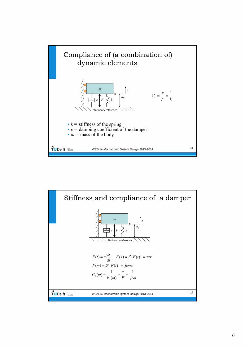

10
WB2414-Mechatronic System Design 2013-2014 19DelftUniversity ofTechnology
High damping
180
0
Log |xF|
Log ωω0
Phase
WB2414-Mechatronic System Design 2013-2014 20DelftUniversity ofTechnology
Extreme damping two first order systems
180
0
Log |xF|
Log ωω0
Phase
11
WB2414-Mechatronic System Design 2013-2014 21DelftUniversity ofTechnology
Contents
bull Stiffness in Precision Engineering
bull Passive and active stiffness
bull Compliance of (a combination of) dynamic elements
bull Dynamic modelling of damped mass‐spring systems
bull Transmissibility
bull Coupled mass‐spring systems
bull Eigenmodes eigenfrequencies and modeshapes
bull Standard mechanical frequency responses
WB2414-Mechatronic System Design 2013-2014 22DelftUniversity ofTechnology
Start with second law of NewtonF=ma
2
2
d d( ) )
d d
x xF t m c kx
t t
2 ( )( ) ( )F s x m ct s sF k
t 2
20 0
( )( ) ( )2 1
sCxC F
s sFt
1sC
k 0
k
m
2
c
km
t 22
11
( ) ( )1
mx kC s sm csF ms cs k sk k
FRF
With only positive imaginary terms (Fourier)
m
x0k
Stationary reference
c F
x
Laplace gives
12
WB2414-Mechatronic System Design 2013-2014 23DelftUniversity ofTechnology
The magnitude and the phase
Start with s=jω
2 22
20 0
( )
1 2
st
CC
And phase angle φ is ndash arctan (imaginaryreal of the denominator)
WB2414-Mechatronic System Design 2013-2014 24DelftUniversity ofTechnology
Compliance Bode plot with damping
m
x0k
Stationary reference
c F
x
bull k = 104 Nm
bull m = 025 kg
13
WB2414-Mechatronic System Design 2013-2014 25DelftUniversity ofTechnology
The damping ratio is related to the pole location in the Laplace plane
s j Poles are those values of s where denominator of Ct is zero
2t
s2
20 0
1
1 2 1
Cx kCm cs s sF sk k
1 2 and d dp j p j
0s
t 1 02
2
If 0 then 0 no damping
and and 1
c
CC p j p j
ms
k
Re
Im
WB2414-Mechatronic System Design 2013-2014 26DelftUniversity ofTechnology
Critical damping ratio
Re
Im
= 1
lt 1
lt 1
gt 1
gt 1
1
2t
s2
20 0
1
1 2 1
Cx kCm cs s sF sk k
1 2 and d dp j p j
s
2
s s2 2t
2
If 2 then 1 and
1
11 2 1 1
c km
C C CkCm cs m m sms s s sk k k k k
14
WB2414-Mechatronic System Design 2013-2014 27DelftUniversity ofTechnology
Above critical damping the mass-spring system reduces to two first order systems
Log |xF|
Log ω
Spring line
Mass line (‐2)
Damper line (‐1)Spring line
Damper line
180 Mass line
1s
s
xC
F k
2
1m
m
xC
F m
1d
d
xC
F c
Phase
90
0
180
0
ω0
020
1 1
k
k m m
WB2414-Mechatronic System Design 2013-2014 28DelftUniversity ofTechnology
Effect of the damping ratio on the stepresponse
At ζ = 1 no overshootCritical dampingtime domain related term
15
WB2414-Mechatronic System Design 2013-2014 29DelftUniversity ofTechnology
Energy at natural Frequency
Energy will be ldquotrappedrdquo in the systemWhen excited in this frequency the amplitude will continue to rise
For electrical engineering (frequency domain) the quality factor Q is defined for this property as resonators are also useful But in mechanical engineering the time domain related term ldquodamping ratiordquo is more commonly used
Letrsquos bridge the gap
WB2414-Mechatronic System Design 2013-2014 30DelftUniversity ofTechnology
Q=100 means peak level at 100 times spring-line level
bull k = 104 Nm
bull m = 025 kg
m
x0k
Stationary reference
c F
x
At Q = 1 no resonance peakfrequency domain related term
16
WB2414-Mechatronic System Design 2013-2014 31DelftUniversity ofTechnology
Relation Q and
1 1
2 2Q
Q
1 1
2 2EE ME
ME EE
Electrical vs mechanical Time vs frequency domain
WB2414-Mechatronic System Design 2013-2014 32DelftUniversity ofTechnology
Velocity response kinetic energy
2
20 0
dd
2 1
s
xv sxtF F F
s C
s s
m
x0k
Stationary reference
c F
x
bull k = 104 Nm
bull m = 025 kg
17
WB2414-Mechatronic System Design 2013-2014 33DelftUniversity ofTechnology
Resonance is energy storage damping is velocity related
bull Driving force is in phase with velocity at resonance
bull Power is Force times speed
bull Max energy transfer at resonance
bull Damper is just the opposite
bull Q tells something about the height of the resonance peak
Maximum energy stored2
Energy lost per cycleQ
WB2414-Mechatronic System Design 2013-2014 34DelftUniversity ofTechnology
Q and energy
18
WB2414-Mechatronic System Design 2013-2014 35DelftUniversity ofTechnology
Contents
bull Stiffness in Precision Engineering
bull Passive and active stiffness
bull Compliance of (a combination of) dynamic elements
bull Dynamic modelling of damped mass‐spring systems
bull Transmissibility
bull Coupled mass‐spring systems
bull Eigenmodes eigenfrequencies and modeshapes
bull Standard mechanical frequency responses
WB2414-Mechatronic System Design 2013-2014 36DelftUniversity ofTechnology
Transmissibility transfer of motion through the support of a dynamic system
2m f m
tm f m2
d d( )( ) ( )
d d
x x xF t m c k x x
t t
02
20 0
2 1
2 1
m
f
sx
s sx
0
k
m
2
c
km
22
1
1
m
f
csx cs k k
m csx ms cs k sk k
With
The force acting on the body equals
m xm
kxfTable
c
Stationary reference
2m f( ) ( )x ms cs k x cs k
19
WB2414-Mechatronic System Design 2013-2014 37DelftUniversity ofTechnology
Bode plot of transmissibility
WB2414-Mechatronic System Design 2013-2014 38DelftUniversity ofTechnology
Contents
bull Stiffness in Precision Engineering
bull Passive and active stiffness
bull Compliance of (a combination of) dynamic elements
bull Dynamic modelling of damped mass‐spring systems
bull Transmissibility
bull Coupled mass‐spring systems
bull Eigenmodes eigenfrequencies and modeshapes
bull Standard mechanical frequency responses
20
WB2414-Mechatronic System Design 2013-2014 39DelftUniversity ofTechnology
Coupled mass-spring systems
m1
x1
km2
x2
F
Stationary reference
Elastically coupled Multi-body or finite-element non-rigid body dynamics
WB2414-Mechatronic System Design 2013-2014 40DelftUniversity ofTechnology
Which statement is true There is a frequency where
m1
x1
km2
x2
F
Stationary reference
1 Only m1 will resonate with k
2 Only m2 will resonate with k
3 Only m1 will stop moving
4 Only m2 will stop moving
21
WB2414-Mechatronic System Design 2013-2014 41DelftUniversity ofTechnology
Equations of Motion
bull First body
bull Second body
m1
x1
km2
x2
F
Stationary reference
21
1 1 22
21 1 1 2
22
2 1 22
22 2 1 2
d ( )( ) ( )
d
( ) ( )
d ( )( )
d
( ) ( )
x tm F t k x x
t
m s x s F k x x
x tm k x x
t
m s x s k x x
note The domain (s or t) is only mentioned once
WB2414-Mechatronic System Design 2013-2014 42DelftUniversity ofTechnology
Resulting equations in the Laplace domain
21 2
4 21 2 1 2
24 2
1 2 1 2
( )
( )
x m s ks
F m m s k m m s
x ks
F m m s k m m s
Low values of s at low frequencies
1 2
21 2
1( ) ( )
x xs s
F F m m s
High values of s at high frequencies
1 22 4
1 1 2
1( ) ( )
x x ks s
F m s F m m s
Fourth order system
22
WB2414-Mechatronic System Design 2013-2014 43DelftUniversity ofTechnology
At mid frequency the driven body shows a strange effect
Combination of poles and zeros
21 2
4 21 2 1 2
24 2
1 2 1 2
2 2
2
1
( )
w
then the compliance of shows a dip
hen
k
m
x m s k
F m m s k m m s
x ks
F m m s k m
s
x
m s
WB2414-Mechatronic System Design 2013-2014 44DelftUniversity ofTechnology
m1 = 01 m2 an actuated large mass by a lighter actuator
1
2
4
3
3
25 10 kg
25 10
1
kg
Nm0
m
m
k
21 2
4 21 2 1 2
24 2
1 2 1 2
( )
( )
x m s ks
F m m s k m m s
x ks
F m m s k m m s
1 2
21 2
1LF ( ) ( )
x x
s sF F m m s
1 22 4
1 1 2
1HF ( ) ( )
x x ks s
F m s F m m s
23
WB2414-Mechatronic System Design 2013-2014 45DelftUniversity ofTechnology
m1 = m2 motor mass is optimisedto the driven mass
31
32
4
25 10 kg
25 10
10
kg
Nm
m
m
k
21 2
4 21 2 1 2
24 2
1 2 1 2
( )
( )
x m s ks
F m m s k m m s
x ks
F m m s k m m s
WB2414-Mechatronic System Design 2013-2014 46DelftUniversity ofTechnology
m1 = 10 m2 parasitic resonances
1
2
4
3
025 kg
25 10 kg
1 m0 N
m
m
k
21 2
4 21 2 1 2
24 2
1 2 1 2
( )
( )
x m s ks
F m m s k m m s
x ks
F m m s k m m s
24
WB2414-Mechatronic System Design 2013-2014 47DelftUniversity ofTechnology
Contents
bull Stiffness in Precision Engineering
bull Passive and active stiffness
bull Compliance of (a combination of) dynamic elements
bull Dynamic modelling of damped mass spring systems
bull Transmissibility
bull Coupled mass spring systems
bull Eigenmodes eigenfrequencies and modeshapes
bull Standard mechanical frequency responses
WB2414-Mechatronic System Design 2013-2014 48DelftUniversity ofTechnology
Eigenmodes
When excited non‐rigid bodies and complex mass‐spring systems
vibrate in different eigenmodes with two main properties
bull Eigenfrequency the related natural (resonance) frequency
bull Mode‐shape the deformation that corresponds with the eigenmode described in a multiple degree of freedom ldquoshape‐
function rdquo
Modelling is done by discretisation of the system in multiple mass‐
spring systems
bull The shape function reduces to an eigenvector with one value for
each body for the relative motion magnitude and direction (sign)
25
WB2414-Mechatronic System Design 2013-2014 49DelftUniversity ofTechnology
Mode-shape of complex non-rigid body
WB2414-Mechatronic System Design 2013-2014 50DelftUniversity ofTechnology
Eigenfrequencies of multiple eigenmodes in 6-DOF
26
WB2414-Mechatronic System Design 2013-2014 51DelftUniversity ofTechnology
Eigen modes of coupled bodies
1
1
1
2
1
1
WB2414-Mechatronic System Design 2013-2014 52DelftUniversity ofTechnology
Multiplicative expression shows two resonating eigenfrequencies
c
c
2122 2
1 2
1 2
1 2
22 2
1 2 c
1 1
with
1
xm s k
F m m s m s k
m mm
m m
x k
F m m s m s k
2
1 2 24 2 4 2
1 2 1 2 1 2 1 2
x m s k x k
F m m s k m m s F m m s k m m s
Starting with
11 2
2
00
m m
k
M
27
WB2414-Mechatronic System Design 2013-2014 53DelftUniversity ofTechnology
Additive expression
bull Can be written as a combination of two eigenmodes with modal
mass and stiffness using eigenvector
21 1 222 2
1 2 1c
c 2
22 2
1 2 c
1 1 with
1
x m mm s k m
F m m s m s k m m
x k
F m m s m s k
2 22 2
2 2
c 1 1
1 2 1 212 2 2 2
1 2
1 2 1 222 2 2 2
1 2
2 2
1 2 1 22 2
c 1 1 2 2
1 1=
( )
1 1=
( )
m m
m m m mx
F m m s m s k s s
m m
m m m mx
F m m s m s k s s
m m
1
1
1
2
1
1
i i i
WB2414-Mechatronic System Design 2013-2014 54DelftUniversity ofTechnology
Modes 1 and 2 combined
1 212 2
1 222
22
2
1 1 2 2
1 22
1 12
2 2
1
1
m
m mx
F s s
m
m mx
F s s
m
28
WB2414-Mechatronic System Design 2013-2014 55DelftUniversity ofTechnology
i
Theory on modal decompositionbull General equation of motion (vectormatrix) of finite element system
bull General transfer function
bull In absence of external force
bull Decoupled by eigenvalue problem where is the eigenvector
2
2
20
( ) ( ) ( )
( ) ( ) ( )
( ) ( ) 0
0i i
Mx t Kx t F t
Ms x s Kx s F s
Ms x s Kx s
K M
WB2414-Mechatronic System Design 2013-2014 56DelftUniversity ofTechnology
Modal mass and stiffness orthogonality of eigenmodes
bull Modal mass
bull Modal Stiffness
20
0 ( )
0 ( )
i j
i i i
i j
i i i i i
M i j
M
K i j
K
29
WB2414-Mechatronic System Design 2013-2014 57DelftUniversity ofTechnology
Scaling
bull Length of eigenvector is not defined (only the direction)
bull Three scaling methods are often applied
1 1
2 max 1
3 1
i i i
i
i
i
M
WB2414-Mechatronic System Design 2013-2014 58DelftUniversity ofTechnology
Modal coordinates
bull When qiequals the motion of eigenmode i then the total displacement vector x(t) will be
where qi is called the modal coordinate
bull This gives the following displacement for DOF xk(t)
1 1 2 2 n n
1 1 2 2 n
( ) ( ) ( ) ( )
( ) ( ) ( ) ( )k k k n k
x t q t q t q t
x t q t q t q t
30
WB2414-Mechatronic System Design 2013-2014 59DelftUniversity ofTechnology
Full set of uncoupled equations
1
1 2 n
n
2
( ) ( )
( )
with and ( ) ( )
( )
applied to ( ) ( ) ( )
gives with pre-multiplication with
( ) ( ) ( )
i
x t q t
q t
q t q t
q t
Ms x s Kx s F s
M q t K q t F t
WB2414-Mechatronic System Design 2013-2014 60DelftUniversity ofTechnology
This can be transformed into a combined transfer function
bull The response of DOF by
eigenmode i on force equals
bull The total response equals
2
i
n n 2
1 1
( )
( )
i k i
k i i
i k i
i ik k i ii
xs
F s
x xs
F F s
xkF
31
WB2414-Mechatronic System Design 2013-2014 61DelftUniversity ofTechnology
Graphical representation
bull The modal coordinate is
represented by the angle of the lever or the displacement at distance 1
bull Modal mass and stiffness are connected to the modal
coordinate
bull The eigenvectors determine the
ratio of ldquocontrollabilityrdquo of actuator and ldquoobservabilityrdquo of sensor
2
i
( ) i k i
k i i
xs
F s
WB2414-Mechatronic System Design 2013-2014 62DelftUniversity ofTechnology
Effective modal values
As perceived at the actuator
32
WB2414-Mechatronic System Design 2013-2014 63DelftUniversity ofTechnology
Mass on leafspring two eigenmodes
F
x
F
x
y
x
a Mode shape 1 b Mode shape 2
Stationary reference Stationary reference
WB2414-Mechatronic System Design 2013-2014 64DelftUniversity ofTechnology
Modes 1 and 2 combined by measuring non co-local with the force
‐2 slope with ‐360o
phase is non‐minimum phase system
33
WB2414-Mechatronic System Design 2013-2014 65DelftUniversity ofTechnology
Non-minimum phase step response
WB2414-Mechatronic System Design 2013-2014 66DelftUniversity ofTechnology
Summary of termsbull Eigenvector
bull Vector with terms that represent the relative motion amplitude of each element in the
discretised structure It is the discretised ldquoshape functionrdquo
bull Scaling is at will as long as the scaling is equal for all properties of that eigenmode
bull Modal mass and stiffnessbull relate to the mass and stiffness matrix by double multiplication with the eigenvector
bull Scaling of the eigenvector also scales the modal mass and stiffness (squared)
bull Modal coordinatesbull Represent the motion of the eigenmode at the location of the modal mass and
stiffness
bull It is used to determine the motion of all elements with the eigenvector and as such it
also depends on the chosen scaling
bull Effective modal mass and stiffness
bull Is the modal mass and stiffness as perceived at the actuator position It is calculated
from the modal mass and stiffness by dividing by the corresponding eigenvector term
squared hence the chosen scaling no longer plays a role
i i i i i iM K
34
WB2414-Mechatronic System Design 2013-2014 67DelftUniversity ofTechnology
Mode-shape of complex non-rigid body
WB2414-Mechatronic System Design 2013-2014 68DelftUniversity ofTechnology
Contents
bull Stiffness in Precision Engineering
bull Passive and active stiffness
bull Compliance of (a combination of) dynamic elements
bull Dynamic modelling of damped mass‐spring systems
bull Transmissibility
bull Coupled mass‐spring systems
bull Eigenmodes eigenfrequencies and modeshapes
bull Standard mechanical frequency responses
35
WB2414-Mechatronic System Design 2013-2014 69DelftUniversity ofTechnology
Typical combination of two eigenmodes one rigid and one non-rigid
bullActuated at xa
bullSensed at different locations
WB2414-Mechatronic System Design 2013-2014 70DelftUniversity ofTechnology
Different combinations of two eigenmodes
36
WB2414-Mechatronic System Design 2013-2014 71DelftUniversity ofTechnology
4 types of responses result
WB2414-Mechatronic System Design 2013-2014 72DelftUniversity ofTechnology
Eigenfrequencies of multiple eigenmodes in 6-DOF

11
WB2414-Mechatronic System Design 2013-2014 21DelftUniversity ofTechnology
Contents
bull Stiffness in Precision Engineering
bull Passive and active stiffness
bull Compliance of (a combination of) dynamic elements
bull Dynamic modelling of damped mass‐spring systems
bull Transmissibility
bull Coupled mass‐spring systems
bull Eigenmodes eigenfrequencies and modeshapes
bull Standard mechanical frequency responses
WB2414-Mechatronic System Design 2013-2014 22DelftUniversity ofTechnology
Start with second law of NewtonF=ma
2
2
d d( ) )
d d
x xF t m c kx
t t
2 ( )( ) ( )F s x m ct s sF k
t 2
20 0
( )( ) ( )2 1
sCxC F
s sFt
1sC
k 0
k
m
2
c
km
t 22
11
( ) ( )1
mx kC s sm csF ms cs k sk k
FRF
With only positive imaginary terms (Fourier)
m
x0k
Stationary reference
c F
x
Laplace gives
12
WB2414-Mechatronic System Design 2013-2014 23DelftUniversity ofTechnology
The magnitude and the phase
Start with s=jω
2 22
20 0
( )
1 2
st
CC
And phase angle φ is ndash arctan (imaginaryreal of the denominator)
WB2414-Mechatronic System Design 2013-2014 24DelftUniversity ofTechnology
Compliance Bode plot with damping
m
x0k
Stationary reference
c F
x
bull k = 104 Nm
bull m = 025 kg
13
WB2414-Mechatronic System Design 2013-2014 25DelftUniversity ofTechnology
The damping ratio is related to the pole location in the Laplace plane
s j Poles are those values of s where denominator of Ct is zero
2t
s2
20 0
1
1 2 1
Cx kCm cs s sF sk k
1 2 and d dp j p j
0s
t 1 02
2
If 0 then 0 no damping
and and 1
c
CC p j p j
ms
k
Re
Im
WB2414-Mechatronic System Design 2013-2014 26DelftUniversity ofTechnology
Critical damping ratio
Re
Im
= 1
lt 1
lt 1
gt 1
gt 1
1
2t
s2
20 0
1
1 2 1
Cx kCm cs s sF sk k
1 2 and d dp j p j
s
2
s s2 2t
2
If 2 then 1 and
1
11 2 1 1
c km
C C CkCm cs m m sms s s sk k k k k
14
WB2414-Mechatronic System Design 2013-2014 27DelftUniversity ofTechnology
Above critical damping the mass-spring system reduces to two first order systems
Log |xF|
Log ω
Spring line
Mass line (‐2)
Damper line (‐1)Spring line
Damper line
180 Mass line
1s
s
xC
F k
2
1m
m
xC
F m
1d
d
xC
F c
Phase
90
0
180
0
ω0
020
1 1
k
k m m
WB2414-Mechatronic System Design 2013-2014 28DelftUniversity ofTechnology
Effect of the damping ratio on the stepresponse
At ζ = 1 no overshootCritical dampingtime domain related term
15
WB2414-Mechatronic System Design 2013-2014 29DelftUniversity ofTechnology
Energy at natural Frequency
Energy will be ldquotrappedrdquo in the systemWhen excited in this frequency the amplitude will continue to rise
For electrical engineering (frequency domain) the quality factor Q is defined for this property as resonators are also useful But in mechanical engineering the time domain related term ldquodamping ratiordquo is more commonly used
Letrsquos bridge the gap
WB2414-Mechatronic System Design 2013-2014 30DelftUniversity ofTechnology
Q=100 means peak level at 100 times spring-line level
bull k = 104 Nm
bull m = 025 kg
m
x0k
Stationary reference
c F
x
At Q = 1 no resonance peakfrequency domain related term
16
WB2414-Mechatronic System Design 2013-2014 31DelftUniversity ofTechnology
Relation Q and
1 1
2 2Q
Q
1 1
2 2EE ME
ME EE
Electrical vs mechanical Time vs frequency domain
WB2414-Mechatronic System Design 2013-2014 32DelftUniversity ofTechnology
Velocity response kinetic energy
2
20 0
dd
2 1
s
xv sxtF F F
s C
s s
m
x0k
Stationary reference
c F
x
bull k = 104 Nm
bull m = 025 kg
17
WB2414-Mechatronic System Design 2013-2014 33DelftUniversity ofTechnology
Resonance is energy storage damping is velocity related
bull Driving force is in phase with velocity at resonance
bull Power is Force times speed
bull Max energy transfer at resonance
bull Damper is just the opposite
bull Q tells something about the height of the resonance peak
Maximum energy stored2
Energy lost per cycleQ
WB2414-Mechatronic System Design 2013-2014 34DelftUniversity ofTechnology
Q and energy
18
WB2414-Mechatronic System Design 2013-2014 35DelftUniversity ofTechnology
Contents
bull Stiffness in Precision Engineering
bull Passive and active stiffness
bull Compliance of (a combination of) dynamic elements
bull Dynamic modelling of damped mass‐spring systems
bull Transmissibility
bull Coupled mass‐spring systems
bull Eigenmodes eigenfrequencies and modeshapes
bull Standard mechanical frequency responses
WB2414-Mechatronic System Design 2013-2014 36DelftUniversity ofTechnology
Transmissibility transfer of motion through the support of a dynamic system
2m f m
tm f m2
d d( )( ) ( )
d d
x x xF t m c k x x
t t
02
20 0
2 1
2 1
m
f
sx
s sx
0
k
m
2
c
km
22
1
1
m
f
csx cs k k
m csx ms cs k sk k
With
The force acting on the body equals
m xm
kxfTable
c
Stationary reference
2m f( ) ( )x ms cs k x cs k
19
WB2414-Mechatronic System Design 2013-2014 37DelftUniversity ofTechnology
Bode plot of transmissibility
WB2414-Mechatronic System Design 2013-2014 38DelftUniversity ofTechnology
Contents
bull Stiffness in Precision Engineering
bull Passive and active stiffness
bull Compliance of (a combination of) dynamic elements
bull Dynamic modelling of damped mass‐spring systems
bull Transmissibility
bull Coupled mass‐spring systems
bull Eigenmodes eigenfrequencies and modeshapes
bull Standard mechanical frequency responses
20
WB2414-Mechatronic System Design 2013-2014 39DelftUniversity ofTechnology
Coupled mass-spring systems
m1
x1
km2
x2
F
Stationary reference
Elastically coupled Multi-body or finite-element non-rigid body dynamics
WB2414-Mechatronic System Design 2013-2014 40DelftUniversity ofTechnology
Which statement is true There is a frequency where
m1
x1
km2
x2
F
Stationary reference
1 Only m1 will resonate with k
2 Only m2 will resonate with k
3 Only m1 will stop moving
4 Only m2 will stop moving
21
WB2414-Mechatronic System Design 2013-2014 41DelftUniversity ofTechnology
Equations of Motion
bull First body
bull Second body
m1
x1
km2
x2
F
Stationary reference
21
1 1 22
21 1 1 2
22
2 1 22
22 2 1 2
d ( )( ) ( )
d
( ) ( )
d ( )( )
d
( ) ( )
x tm F t k x x
t
m s x s F k x x
x tm k x x
t
m s x s k x x
note The domain (s or t) is only mentioned once
WB2414-Mechatronic System Design 2013-2014 42DelftUniversity ofTechnology
Resulting equations in the Laplace domain
21 2
4 21 2 1 2
24 2
1 2 1 2
( )
( )
x m s ks
F m m s k m m s
x ks
F m m s k m m s
Low values of s at low frequencies
1 2
21 2
1( ) ( )
x xs s
F F m m s
High values of s at high frequencies
1 22 4
1 1 2
1( ) ( )
x x ks s
F m s F m m s
Fourth order system
22
WB2414-Mechatronic System Design 2013-2014 43DelftUniversity ofTechnology
At mid frequency the driven body shows a strange effect
Combination of poles and zeros
21 2
4 21 2 1 2
24 2
1 2 1 2
2 2
2
1
( )
w
then the compliance of shows a dip
hen
k
m
x m s k
F m m s k m m s
x ks
F m m s k m
s
x
m s
WB2414-Mechatronic System Design 2013-2014 44DelftUniversity ofTechnology
m1 = 01 m2 an actuated large mass by a lighter actuator
1
2
4
3
3
25 10 kg
25 10
1
kg
Nm0
m
m
k
21 2
4 21 2 1 2
24 2
1 2 1 2
( )
( )
x m s ks
F m m s k m m s
x ks
F m m s k m m s
1 2
21 2
1LF ( ) ( )
x x
s sF F m m s
1 22 4
1 1 2
1HF ( ) ( )
x x ks s
F m s F m m s
23
WB2414-Mechatronic System Design 2013-2014 45DelftUniversity ofTechnology
m1 = m2 motor mass is optimisedto the driven mass
31
32
4
25 10 kg
25 10
10
kg
Nm
m
m
k
21 2
4 21 2 1 2
24 2
1 2 1 2
( )
( )
x m s ks
F m m s k m m s
x ks
F m m s k m m s
WB2414-Mechatronic System Design 2013-2014 46DelftUniversity ofTechnology
m1 = 10 m2 parasitic resonances
1
2
4
3
025 kg
25 10 kg
1 m0 N
m
m
k
21 2
4 21 2 1 2
24 2
1 2 1 2
( )
( )
x m s ks
F m m s k m m s
x ks
F m m s k m m s
24
WB2414-Mechatronic System Design 2013-2014 47DelftUniversity ofTechnology
Contents
bull Stiffness in Precision Engineering
bull Passive and active stiffness
bull Compliance of (a combination of) dynamic elements
bull Dynamic modelling of damped mass spring systems
bull Transmissibility
bull Coupled mass spring systems
bull Eigenmodes eigenfrequencies and modeshapes
bull Standard mechanical frequency responses
WB2414-Mechatronic System Design 2013-2014 48DelftUniversity ofTechnology
Eigenmodes
When excited non‐rigid bodies and complex mass‐spring systems
vibrate in different eigenmodes with two main properties
bull Eigenfrequency the related natural (resonance) frequency
bull Mode‐shape the deformation that corresponds with the eigenmode described in a multiple degree of freedom ldquoshape‐
function rdquo
Modelling is done by discretisation of the system in multiple mass‐
spring systems
bull The shape function reduces to an eigenvector with one value for
each body for the relative motion magnitude and direction (sign)
25
WB2414-Mechatronic System Design 2013-2014 49DelftUniversity ofTechnology
Mode-shape of complex non-rigid body
WB2414-Mechatronic System Design 2013-2014 50DelftUniversity ofTechnology
Eigenfrequencies of multiple eigenmodes in 6-DOF
26
WB2414-Mechatronic System Design 2013-2014 51DelftUniversity ofTechnology
Eigen modes of coupled bodies
1
1
1
2
1
1
WB2414-Mechatronic System Design 2013-2014 52DelftUniversity ofTechnology
Multiplicative expression shows two resonating eigenfrequencies
c
c
2122 2
1 2
1 2
1 2
22 2
1 2 c
1 1
with
1
xm s k
F m m s m s k
m mm
m m
x k
F m m s m s k
2
1 2 24 2 4 2
1 2 1 2 1 2 1 2
x m s k x k
F m m s k m m s F m m s k m m s
Starting with
11 2
2
00
m m
k
M
27
WB2414-Mechatronic System Design 2013-2014 53DelftUniversity ofTechnology
Additive expression
bull Can be written as a combination of two eigenmodes with modal
mass and stiffness using eigenvector
21 1 222 2
1 2 1c
c 2
22 2
1 2 c
1 1 with
1
x m mm s k m
F m m s m s k m m
x k
F m m s m s k
2 22 2
2 2
c 1 1
1 2 1 212 2 2 2
1 2
1 2 1 222 2 2 2
1 2
2 2
1 2 1 22 2
c 1 1 2 2
1 1=
( )
1 1=
( )
m m
m m m mx
F m m s m s k s s
m m
m m m mx
F m m s m s k s s
m m
1
1
1
2
1
1
i i i
WB2414-Mechatronic System Design 2013-2014 54DelftUniversity ofTechnology
Modes 1 and 2 combined
1 212 2
1 222
22
2
1 1 2 2
1 22
1 12
2 2
1
1
m
m mx
F s s
m
m mx
F s s
m
28
WB2414-Mechatronic System Design 2013-2014 55DelftUniversity ofTechnology
i
Theory on modal decompositionbull General equation of motion (vectormatrix) of finite element system
bull General transfer function
bull In absence of external force
bull Decoupled by eigenvalue problem where is the eigenvector
2
2
20
( ) ( ) ( )
( ) ( ) ( )
( ) ( ) 0
0i i
Mx t Kx t F t
Ms x s Kx s F s
Ms x s Kx s
K M
WB2414-Mechatronic System Design 2013-2014 56DelftUniversity ofTechnology
Modal mass and stiffness orthogonality of eigenmodes
bull Modal mass
bull Modal Stiffness
20
0 ( )
0 ( )
i j
i i i
i j
i i i i i
M i j
M
K i j
K
29
WB2414-Mechatronic System Design 2013-2014 57DelftUniversity ofTechnology
Scaling
bull Length of eigenvector is not defined (only the direction)
bull Three scaling methods are often applied
1 1
2 max 1
3 1
i i i
i
i
i
M
WB2414-Mechatronic System Design 2013-2014 58DelftUniversity ofTechnology
Modal coordinates
bull When qiequals the motion of eigenmode i then the total displacement vector x(t) will be
where qi is called the modal coordinate
bull This gives the following displacement for DOF xk(t)
1 1 2 2 n n
1 1 2 2 n
( ) ( ) ( ) ( )
( ) ( ) ( ) ( )k k k n k
x t q t q t q t
x t q t q t q t
30
WB2414-Mechatronic System Design 2013-2014 59DelftUniversity ofTechnology
Full set of uncoupled equations
1
1 2 n
n
2
( ) ( )
( )
with and ( ) ( )
( )
applied to ( ) ( ) ( )
gives with pre-multiplication with
( ) ( ) ( )
i
x t q t
q t
q t q t
q t
Ms x s Kx s F s
M q t K q t F t
WB2414-Mechatronic System Design 2013-2014 60DelftUniversity ofTechnology
This can be transformed into a combined transfer function
bull The response of DOF by
eigenmode i on force equals
bull The total response equals
2
i
n n 2
1 1
( )
( )
i k i
k i i
i k i
i ik k i ii
xs
F s
x xs
F F s
xkF
31
WB2414-Mechatronic System Design 2013-2014 61DelftUniversity ofTechnology
Graphical representation
bull The modal coordinate is
represented by the angle of the lever or the displacement at distance 1
bull Modal mass and stiffness are connected to the modal
coordinate
bull The eigenvectors determine the
ratio of ldquocontrollabilityrdquo of actuator and ldquoobservabilityrdquo of sensor
2
i
( ) i k i
k i i
xs
F s
WB2414-Mechatronic System Design 2013-2014 62DelftUniversity ofTechnology
Effective modal values
As perceived at the actuator
32
WB2414-Mechatronic System Design 2013-2014 63DelftUniversity ofTechnology
Mass on leafspring two eigenmodes
F
x
F
x
y
x
a Mode shape 1 b Mode shape 2
Stationary reference Stationary reference
WB2414-Mechatronic System Design 2013-2014 64DelftUniversity ofTechnology
Modes 1 and 2 combined by measuring non co-local with the force
‐2 slope with ‐360o
phase is non‐minimum phase system
33
WB2414-Mechatronic System Design 2013-2014 65DelftUniversity ofTechnology
Non-minimum phase step response
WB2414-Mechatronic System Design 2013-2014 66DelftUniversity ofTechnology
Summary of termsbull Eigenvector
bull Vector with terms that represent the relative motion amplitude of each element in the
discretised structure It is the discretised ldquoshape functionrdquo
bull Scaling is at will as long as the scaling is equal for all properties of that eigenmode
bull Modal mass and stiffnessbull relate to the mass and stiffness matrix by double multiplication with the eigenvector
bull Scaling of the eigenvector also scales the modal mass and stiffness (squared)
bull Modal coordinatesbull Represent the motion of the eigenmode at the location of the modal mass and
stiffness
bull It is used to determine the motion of all elements with the eigenvector and as such it
also depends on the chosen scaling
bull Effective modal mass and stiffness
bull Is the modal mass and stiffness as perceived at the actuator position It is calculated
from the modal mass and stiffness by dividing by the corresponding eigenvector term
squared hence the chosen scaling no longer plays a role
i i i i i iM K
34
WB2414-Mechatronic System Design 2013-2014 67DelftUniversity ofTechnology
Mode-shape of complex non-rigid body
WB2414-Mechatronic System Design 2013-2014 68DelftUniversity ofTechnology
Contents
bull Stiffness in Precision Engineering
bull Passive and active stiffness
bull Compliance of (a combination of) dynamic elements
bull Dynamic modelling of damped mass‐spring systems
bull Transmissibility
bull Coupled mass‐spring systems
bull Eigenmodes eigenfrequencies and modeshapes
bull Standard mechanical frequency responses
35
WB2414-Mechatronic System Design 2013-2014 69DelftUniversity ofTechnology
Typical combination of two eigenmodes one rigid and one non-rigid
bullActuated at xa
bullSensed at different locations
WB2414-Mechatronic System Design 2013-2014 70DelftUniversity ofTechnology
Different combinations of two eigenmodes
36
WB2414-Mechatronic System Design 2013-2014 71DelftUniversity ofTechnology
4 types of responses result
WB2414-Mechatronic System Design 2013-2014 72DelftUniversity ofTechnology
Eigenfrequencies of multiple eigenmodes in 6-DOF
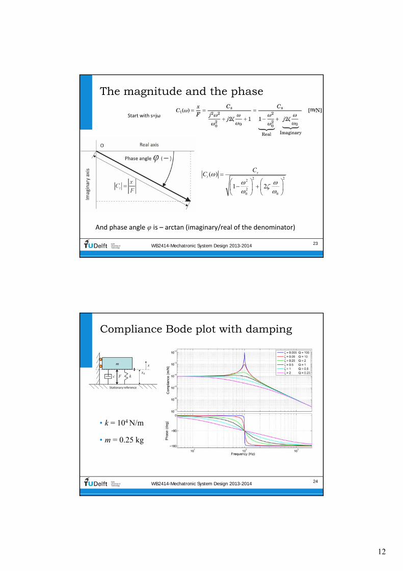
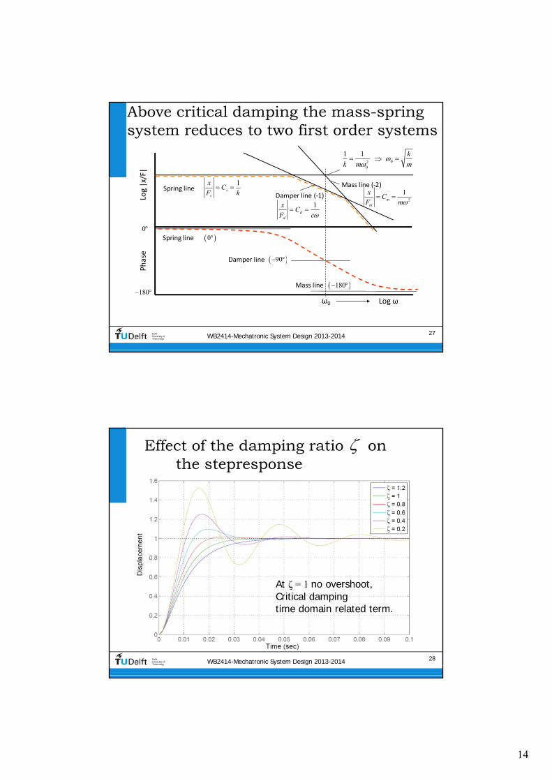
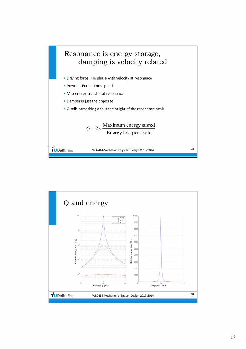
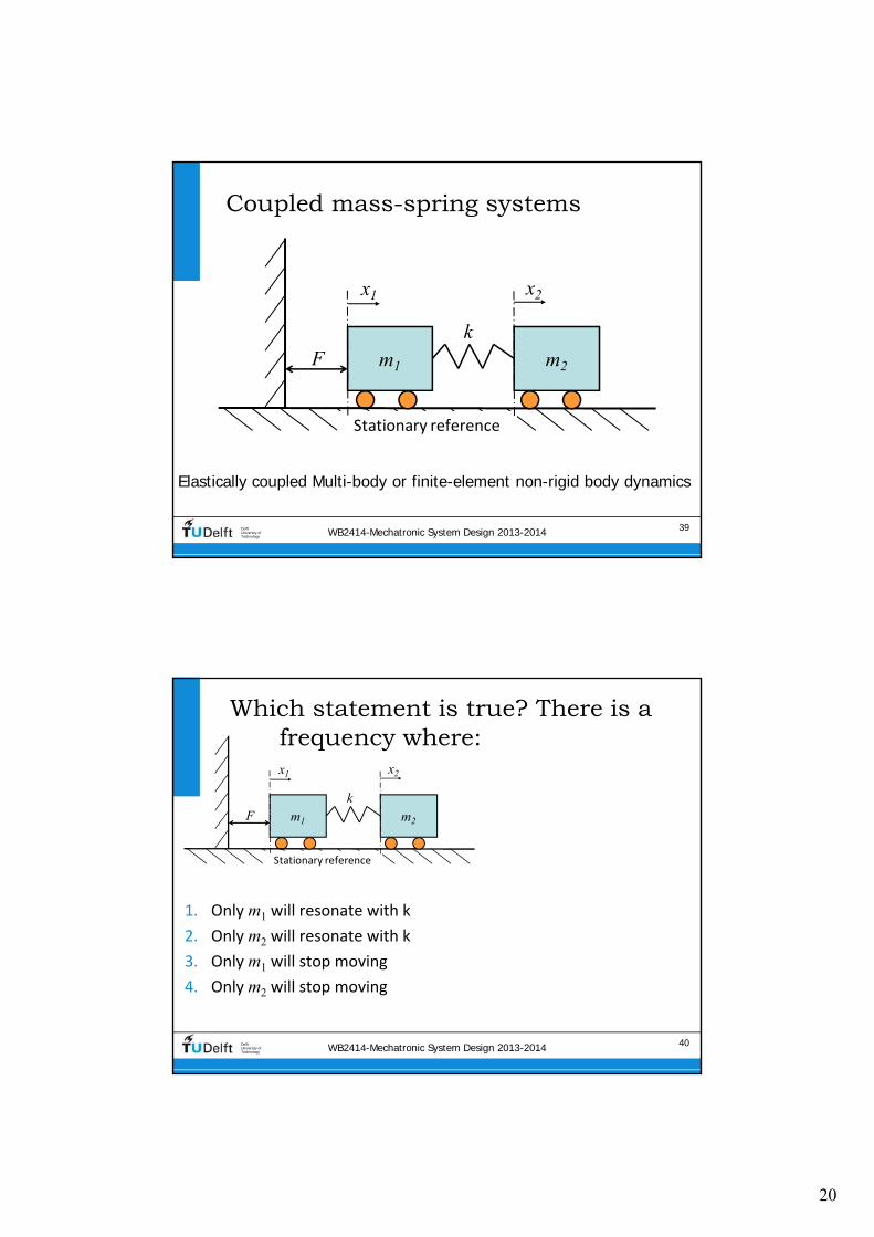
20
WB2414-Mechatronic System Design 2013-2014 39DelftUniversity ofTechnology
Coupled mass-spring systems
m1
x1
km2
x2
F
Stationary reference
Elastically coupled Multi-body or finite-element non-rigid body dynamics
WB2414-Mechatronic System Design 2013-2014 40DelftUniversity ofTechnology
Which statement is true There is a frequency where
m1
x1
km2
x2
F
Stationary reference
1 Only m1 will resonate with k
2 Only m2 will resonate with k
3 Only m1 will stop moving
4 Only m2 will stop moving
21
WB2414-Mechatronic System Design 2013-2014 41DelftUniversity ofTechnology
Equations of Motion
bull First body
bull Second body
m1
x1
km2
x2
F
Stationary reference
21
1 1 22
21 1 1 2
22
2 1 22
22 2 1 2
d ( )( ) ( )
d
( ) ( )
d ( )( )
d
( ) ( )
x tm F t k x x
t
m s x s F k x x
x tm k x x
t
m s x s k x x
note The domain (s or t) is only mentioned once
WB2414-Mechatronic System Design 2013-2014 42DelftUniversity ofTechnology
Resulting equations in the Laplace domain
21 2
4 21 2 1 2
24 2
1 2 1 2
( )
( )
x m s ks
F m m s k m m s
x ks
F m m s k m m s
Low values of s at low frequencies
1 2
21 2
1( ) ( )
x xs s
F F m m s
High values of s at high frequencies
1 22 4
1 1 2
1( ) ( )
x x ks s
F m s F m m s
Fourth order system
22
WB2414-Mechatronic System Design 2013-2014 43DelftUniversity ofTechnology
At mid frequency the driven body shows a strange effect
Combination of poles and zeros
21 2
4 21 2 1 2
24 2
1 2 1 2
2 2
2
1
( )
w
then the compliance of shows a dip
hen
k
m
x m s k
F m m s k m m s
x ks
F m m s k m
s
x
m s
WB2414-Mechatronic System Design 2013-2014 44DelftUniversity ofTechnology
m1 = 01 m2 an actuated large mass by a lighter actuator
1
2
4
3
3
25 10 kg
25 10
1
kg
Nm0
m
m
k
21 2
4 21 2 1 2
24 2
1 2 1 2
( )
( )
x m s ks
F m m s k m m s
x ks
F m m s k m m s
1 2
21 2
1LF ( ) ( )
x x
s sF F m m s
1 22 4
1 1 2
1HF ( ) ( )
x x ks s
F m s F m m s
23
WB2414-Mechatronic System Design 2013-2014 45DelftUniversity ofTechnology
m1 = m2 motor mass is optimisedto the driven mass
31
32
4
25 10 kg
25 10
10
kg
Nm
m
m
k
21 2
4 21 2 1 2
24 2
1 2 1 2
( )
( )
x m s ks
F m m s k m m s
x ks
F m m s k m m s
WB2414-Mechatronic System Design 2013-2014 46DelftUniversity ofTechnology
m1 = 10 m2 parasitic resonances
1
2
4
3
025 kg
25 10 kg
1 m0 N
m
m
k
21 2
4 21 2 1 2
24 2
1 2 1 2
( )
( )
x m s ks
F m m s k m m s
x ks
F m m s k m m s
24
WB2414-Mechatronic System Design 2013-2014 47DelftUniversity ofTechnology
Contents
bull Stiffness in Precision Engineering
bull Passive and active stiffness
bull Compliance of (a combination of) dynamic elements
bull Dynamic modelling of damped mass spring systems
bull Transmissibility
bull Coupled mass spring systems
bull Eigenmodes eigenfrequencies and modeshapes
bull Standard mechanical frequency responses
WB2414-Mechatronic System Design 2013-2014 48DelftUniversity ofTechnology
Eigenmodes
When excited non‐rigid bodies and complex mass‐spring systems
vibrate in different eigenmodes with two main properties
bull Eigenfrequency the related natural (resonance) frequency
bull Mode‐shape the deformation that corresponds with the eigenmode described in a multiple degree of freedom ldquoshape‐
function rdquo
Modelling is done by discretisation of the system in multiple mass‐
spring systems
bull The shape function reduces to an eigenvector with one value for
each body for the relative motion magnitude and direction (sign)
25
WB2414-Mechatronic System Design 2013-2014 49DelftUniversity ofTechnology
Mode-shape of complex non-rigid body
WB2414-Mechatronic System Design 2013-2014 50DelftUniversity ofTechnology
Eigenfrequencies of multiple eigenmodes in 6-DOF
26
WB2414-Mechatronic System Design 2013-2014 51DelftUniversity ofTechnology
Eigen modes of coupled bodies
1
1
1
2
1
1
WB2414-Mechatronic System Design 2013-2014 52DelftUniversity ofTechnology
Multiplicative expression shows two resonating eigenfrequencies
c
c
2122 2
1 2
1 2
1 2
22 2
1 2 c
1 1
with
1
xm s k
F m m s m s k
m mm
m m
x k
F m m s m s k
2
1 2 24 2 4 2
1 2 1 2 1 2 1 2
x m s k x k
F m m s k m m s F m m s k m m s
Starting with
11 2
2
00
m m
k
M
27
WB2414-Mechatronic System Design 2013-2014 53DelftUniversity ofTechnology
Additive expression
bull Can be written as a combination of two eigenmodes with modal
mass and stiffness using eigenvector
21 1 222 2
1 2 1c
c 2
22 2
1 2 c
1 1 with
1
x m mm s k m
F m m s m s k m m
x k
F m m s m s k
2 22 2
2 2
c 1 1
1 2 1 212 2 2 2
1 2
1 2 1 222 2 2 2
1 2
2 2
1 2 1 22 2
c 1 1 2 2
1 1=
( )
1 1=
( )
m m
m m m mx
F m m s m s k s s
m m
m m m mx
F m m s m s k s s
m m
1
1
1
2
1
1
i i i
WB2414-Mechatronic System Design 2013-2014 54DelftUniversity ofTechnology
Modes 1 and 2 combined
1 212 2
1 222
22
2
1 1 2 2
1 22
1 12
2 2
1
1
m
m mx
F s s
m
m mx
F s s
m
28
WB2414-Mechatronic System Design 2013-2014 55DelftUniversity ofTechnology
i
Theory on modal decompositionbull General equation of motion (vectormatrix) of finite element system
bull General transfer function
bull In absence of external force
bull Decoupled by eigenvalue problem where is the eigenvector
2
2
20
( ) ( ) ( )
( ) ( ) ( )
( ) ( ) 0
0i i
Mx t Kx t F t
Ms x s Kx s F s
Ms x s Kx s
K M
WB2414-Mechatronic System Design 2013-2014 56DelftUniversity ofTechnology
Modal mass and stiffness orthogonality of eigenmodes
bull Modal mass
bull Modal Stiffness
20
0 ( )
0 ( )
i j
i i i
i j
i i i i i
M i j
M
K i j
K
29
WB2414-Mechatronic System Design 2013-2014 57DelftUniversity ofTechnology
Scaling
bull Length of eigenvector is not defined (only the direction)
bull Three scaling methods are often applied
1 1
2 max 1
3 1
i i i
i
i
i
M
WB2414-Mechatronic System Design 2013-2014 58DelftUniversity ofTechnology
Modal coordinates
bull When qiequals the motion of eigenmode i then the total displacement vector x(t) will be
where qi is called the modal coordinate
bull This gives the following displacement for DOF xk(t)
1 1 2 2 n n
1 1 2 2 n
( ) ( ) ( ) ( )
( ) ( ) ( ) ( )k k k n k
x t q t q t q t
x t q t q t q t
30
WB2414-Mechatronic System Design 2013-2014 59DelftUniversity ofTechnology
Full set of uncoupled equations
1
1 2 n
n
2
( ) ( )
( )
with and ( ) ( )
( )
applied to ( ) ( ) ( )
gives with pre-multiplication with
( ) ( ) ( )
i
x t q t
q t
q t q t
q t
Ms x s Kx s F s
M q t K q t F t
WB2414-Mechatronic System Design 2013-2014 60DelftUniversity ofTechnology
This can be transformed into a combined transfer function
bull The response of DOF by
eigenmode i on force equals
bull The total response equals
2
i
n n 2
1 1
( )
( )
i k i
k i i
i k i
i ik k i ii
xs
F s
x xs
F F s
xkF
31
WB2414-Mechatronic System Design 2013-2014 61DelftUniversity ofTechnology
Graphical representation
bull The modal coordinate is
represented by the angle of the lever or the displacement at distance 1
bull Modal mass and stiffness are connected to the modal
coordinate
bull The eigenvectors determine the
ratio of ldquocontrollabilityrdquo of actuator and ldquoobservabilityrdquo of sensor
2
i
( ) i k i
k i i
xs
F s
WB2414-Mechatronic System Design 2013-2014 62DelftUniversity ofTechnology
Effective modal values
As perceived at the actuator
32
WB2414-Mechatronic System Design 2013-2014 63DelftUniversity ofTechnology
Mass on leafspring two eigenmodes
F
x
F
x
y
x
a Mode shape 1 b Mode shape 2
Stationary reference Stationary reference
WB2414-Mechatronic System Design 2013-2014 64DelftUniversity ofTechnology
Modes 1 and 2 combined by measuring non co-local with the force
‐2 slope with ‐360o
phase is non‐minimum phase system
33
WB2414-Mechatronic System Design 2013-2014 65DelftUniversity ofTechnology
Non-minimum phase step response
WB2414-Mechatronic System Design 2013-2014 66DelftUniversity ofTechnology
Summary of termsbull Eigenvector
bull Vector with terms that represent the relative motion amplitude of each element in the
discretised structure It is the discretised ldquoshape functionrdquo
bull Scaling is at will as long as the scaling is equal for all properties of that eigenmode
bull Modal mass and stiffnessbull relate to the mass and stiffness matrix by double multiplication with the eigenvector
bull Scaling of the eigenvector also scales the modal mass and stiffness (squared)
bull Modal coordinatesbull Represent the motion of the eigenmode at the location of the modal mass and
stiffness
bull It is used to determine the motion of all elements with the eigenvector and as such it
also depends on the chosen scaling
bull Effective modal mass and stiffness
bull Is the modal mass and stiffness as perceived at the actuator position It is calculated
from the modal mass and stiffness by dividing by the corresponding eigenvector term
squared hence the chosen scaling no longer plays a role
i i i i i iM K
34
WB2414-Mechatronic System Design 2013-2014 67DelftUniversity ofTechnology
Mode-shape of complex non-rigid body
WB2414-Mechatronic System Design 2013-2014 68DelftUniversity ofTechnology
Contents
bull Stiffness in Precision Engineering
bull Passive and active stiffness
bull Compliance of (a combination of) dynamic elements
bull Dynamic modelling of damped mass‐spring systems
bull Transmissibility
bull Coupled mass‐spring systems
bull Eigenmodes eigenfrequencies and modeshapes
bull Standard mechanical frequency responses
35
WB2414-Mechatronic System Design 2013-2014 69DelftUniversity ofTechnology
Typical combination of two eigenmodes one rigid and one non-rigid
bullActuated at xa
bullSensed at different locations
WB2414-Mechatronic System Design 2013-2014 70DelftUniversity ofTechnology
Different combinations of two eigenmodes
36
WB2414-Mechatronic System Design 2013-2014 71DelftUniversity ofTechnology
4 types of responses result
WB2414-Mechatronic System Design 2013-2014 72DelftUniversity ofTechnology
Eigenfrequencies of multiple eigenmodes in 6-DOF

21
WB2414-Mechatronic System Design 2013-2014 41DelftUniversity ofTechnology
Equations of Motion
bull First body
bull Second body
m1
x1
km2
x2
F
Stationary reference
21
1 1 22
21 1 1 2
22
2 1 22
22 2 1 2
d ( )( ) ( )
d
( ) ( )
d ( )( )
d
( ) ( )
x tm F t k x x
t
m s x s F k x x
x tm k x x
t
m s x s k x x
note The domain (s or t) is only mentioned once
WB2414-Mechatronic System Design 2013-2014 42DelftUniversity ofTechnology
Resulting equations in the Laplace domain
21 2
4 21 2 1 2
24 2
1 2 1 2
( )
( )
x m s ks
F m m s k m m s
x ks
F m m s k m m s
Low values of s at low frequencies
1 2
21 2
1( ) ( )
x xs s
F F m m s
High values of s at high frequencies
1 22 4
1 1 2
1( ) ( )
x x ks s
F m s F m m s
Fourth order system
22
WB2414-Mechatronic System Design 2013-2014 43DelftUniversity ofTechnology
At mid frequency the driven body shows a strange effect
Combination of poles and zeros
21 2
4 21 2 1 2
24 2
1 2 1 2
2 2
2
1
( )
w
then the compliance of shows a dip
hen
k
m
x m s k
F m m s k m m s
x ks
F m m s k m
s
x
m s
WB2414-Mechatronic System Design 2013-2014 44DelftUniversity ofTechnology
m1 = 01 m2 an actuated large mass by a lighter actuator
1
2
4
3
3
25 10 kg
25 10
1
kg
Nm0
m
m
k
21 2
4 21 2 1 2
24 2
1 2 1 2
( )
( )
x m s ks
F m m s k m m s
x ks
F m m s k m m s
1 2
21 2
1LF ( ) ( )
x x
s sF F m m s
1 22 4
1 1 2
1HF ( ) ( )
x x ks s
F m s F m m s
23
WB2414-Mechatronic System Design 2013-2014 45DelftUniversity ofTechnology
m1 = m2 motor mass is optimisedto the driven mass
31
32
4
25 10 kg
25 10
10
kg
Nm
m
m
k
21 2
4 21 2 1 2
24 2
1 2 1 2
( )
( )
x m s ks
F m m s k m m s
x ks
F m m s k m m s
WB2414-Mechatronic System Design 2013-2014 46DelftUniversity ofTechnology
m1 = 10 m2 parasitic resonances
1
2
4
3
025 kg
25 10 kg
1 m0 N
m
m
k
21 2
4 21 2 1 2
24 2
1 2 1 2
( )
( )
x m s ks
F m m s k m m s
x ks
F m m s k m m s
24
WB2414-Mechatronic System Design 2013-2014 47DelftUniversity ofTechnology
Contents
bull Stiffness in Precision Engineering
bull Passive and active stiffness
bull Compliance of (a combination of) dynamic elements
bull Dynamic modelling of damped mass spring systems
bull Transmissibility
bull Coupled mass spring systems
bull Eigenmodes eigenfrequencies and modeshapes
bull Standard mechanical frequency responses
WB2414-Mechatronic System Design 2013-2014 48DelftUniversity ofTechnology
Eigenmodes
When excited non‐rigid bodies and complex mass‐spring systems
vibrate in different eigenmodes with two main properties
bull Eigenfrequency the related natural (resonance) frequency
bull Mode‐shape the deformation that corresponds with the eigenmode described in a multiple degree of freedom ldquoshape‐
function rdquo
Modelling is done by discretisation of the system in multiple mass‐
spring systems
bull The shape function reduces to an eigenvector with one value for
each body for the relative motion magnitude and direction (sign)
25
WB2414-Mechatronic System Design 2013-2014 49DelftUniversity ofTechnology
Mode-shape of complex non-rigid body
WB2414-Mechatronic System Design 2013-2014 50DelftUniversity ofTechnology
Eigenfrequencies of multiple eigenmodes in 6-DOF
26
WB2414-Mechatronic System Design 2013-2014 51DelftUniversity ofTechnology
Eigen modes of coupled bodies
1
1
1
2
1
1
WB2414-Mechatronic System Design 2013-2014 52DelftUniversity ofTechnology
Multiplicative expression shows two resonating eigenfrequencies
c
c
2122 2
1 2
1 2
1 2
22 2
1 2 c
1 1
with
1
xm s k
F m m s m s k
m mm
m m
x k
F m m s m s k
2
1 2 24 2 4 2
1 2 1 2 1 2 1 2
x m s k x k
F m m s k m m s F m m s k m m s
Starting with
11 2
2
00
m m
k
M
27
WB2414-Mechatronic System Design 2013-2014 53DelftUniversity ofTechnology
Additive expression
bull Can be written as a combination of two eigenmodes with modal
mass and stiffness using eigenvector
21 1 222 2
1 2 1c
c 2
22 2
1 2 c
1 1 with
1
x m mm s k m
F m m s m s k m m
x k
F m m s m s k
2 22 2
2 2
c 1 1
1 2 1 212 2 2 2
1 2
1 2 1 222 2 2 2
1 2
2 2
1 2 1 22 2
c 1 1 2 2
1 1=
( )
1 1=
( )
m m
m m m mx
F m m s m s k s s
m m
m m m mx
F m m s m s k s s
m m
1
1
1
2
1
1
i i i
WB2414-Mechatronic System Design 2013-2014 54DelftUniversity ofTechnology
Modes 1 and 2 combined
1 212 2
1 222
22
2
1 1 2 2
1 22
1 12
2 2
1
1
m
m mx
F s s
m
m mx
F s s
m
28
WB2414-Mechatronic System Design 2013-2014 55DelftUniversity ofTechnology
i
Theory on modal decompositionbull General equation of motion (vectormatrix) of finite element system
bull General transfer function
bull In absence of external force
bull Decoupled by eigenvalue problem where is the eigenvector
2
2
20
( ) ( ) ( )
( ) ( ) ( )
( ) ( ) 0
0i i
Mx t Kx t F t
Ms x s Kx s F s
Ms x s Kx s
K M
WB2414-Mechatronic System Design 2013-2014 56DelftUniversity ofTechnology
Modal mass and stiffness orthogonality of eigenmodes
bull Modal mass
bull Modal Stiffness
20
0 ( )
0 ( )
i j
i i i
i j
i i i i i
M i j
M
K i j
K
29
WB2414-Mechatronic System Design 2013-2014 57DelftUniversity ofTechnology
Scaling
bull Length of eigenvector is not defined (only the direction)
bull Three scaling methods are often applied
1 1
2 max 1
3 1
i i i
i
i
i
M
WB2414-Mechatronic System Design 2013-2014 58DelftUniversity ofTechnology
Modal coordinates
bull When qiequals the motion of eigenmode i then the total displacement vector x(t) will be
where qi is called the modal coordinate
bull This gives the following displacement for DOF xk(t)
1 1 2 2 n n
1 1 2 2 n
( ) ( ) ( ) ( )
( ) ( ) ( ) ( )k k k n k
x t q t q t q t
x t q t q t q t
30
WB2414-Mechatronic System Design 2013-2014 59DelftUniversity ofTechnology
Full set of uncoupled equations
1
1 2 n
n
2
( ) ( )
( )
with and ( ) ( )
( )
applied to ( ) ( ) ( )
gives with pre-multiplication with
( ) ( ) ( )
i
x t q t
q t
q t q t
q t
Ms x s Kx s F s
M q t K q t F t
WB2414-Mechatronic System Design 2013-2014 60DelftUniversity ofTechnology
This can be transformed into a combined transfer function
bull The response of DOF by
eigenmode i on force equals
bull The total response equals
2
i
n n 2
1 1
( )
( )
i k i
k i i
i k i
i ik k i ii
xs
F s
x xs
F F s
xkF
31
WB2414-Mechatronic System Design 2013-2014 61DelftUniversity ofTechnology
Graphical representation
bull The modal coordinate is
represented by the angle of the lever or the displacement at distance 1
bull Modal mass and stiffness are connected to the modal
coordinate
bull The eigenvectors determine the
ratio of ldquocontrollabilityrdquo of actuator and ldquoobservabilityrdquo of sensor
2
i
( ) i k i
k i i
xs
F s
WB2414-Mechatronic System Design 2013-2014 62DelftUniversity ofTechnology
Effective modal values
As perceived at the actuator
32
WB2414-Mechatronic System Design 2013-2014 63DelftUniversity ofTechnology
Mass on leafspring two eigenmodes
F
x
F
x
y
x
a Mode shape 1 b Mode shape 2
Stationary reference Stationary reference
WB2414-Mechatronic System Design 2013-2014 64DelftUniversity ofTechnology
Modes 1 and 2 combined by measuring non co-local with the force
‐2 slope with ‐360o
phase is non‐minimum phase system
33
WB2414-Mechatronic System Design 2013-2014 65DelftUniversity ofTechnology
Non-minimum phase step response
WB2414-Mechatronic System Design 2013-2014 66DelftUniversity ofTechnology
Summary of termsbull Eigenvector
bull Vector with terms that represent the relative motion amplitude of each element in the
discretised structure It is the discretised ldquoshape functionrdquo
bull Scaling is at will as long as the scaling is equal for all properties of that eigenmode
bull Modal mass and stiffnessbull relate to the mass and stiffness matrix by double multiplication with the eigenvector
bull Scaling of the eigenvector also scales the modal mass and stiffness (squared)
bull Modal coordinatesbull Represent the motion of the eigenmode at the location of the modal mass and
stiffness
bull It is used to determine the motion of all elements with the eigenvector and as such it
also depends on the chosen scaling
bull Effective modal mass and stiffness
bull Is the modal mass and stiffness as perceived at the actuator position It is calculated
from the modal mass and stiffness by dividing by the corresponding eigenvector term
squared hence the chosen scaling no longer plays a role
i i i i i iM K
34
WB2414-Mechatronic System Design 2013-2014 67DelftUniversity ofTechnology
Mode-shape of complex non-rigid body
WB2414-Mechatronic System Design 2013-2014 68DelftUniversity ofTechnology
Contents
bull Stiffness in Precision Engineering
bull Passive and active stiffness
bull Compliance of (a combination of) dynamic elements
bull Dynamic modelling of damped mass‐spring systems
bull Transmissibility
bull Coupled mass‐spring systems
bull Eigenmodes eigenfrequencies and modeshapes
bull Standard mechanical frequency responses
35
WB2414-Mechatronic System Design 2013-2014 69DelftUniversity ofTechnology
Typical combination of two eigenmodes one rigid and one non-rigid
bullActuated at xa
bullSensed at different locations
WB2414-Mechatronic System Design 2013-2014 70DelftUniversity ofTechnology
Different combinations of two eigenmodes
36
WB2414-Mechatronic System Design 2013-2014 71DelftUniversity ofTechnology
4 types of responses result
WB2414-Mechatronic System Design 2013-2014 72DelftUniversity ofTechnology
Eigenfrequencies of multiple eigenmodes in 6-DOF
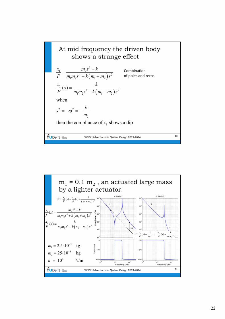
22
WB2414-Mechatronic System Design 2013-2014 43DelftUniversity ofTechnology
At mid frequency the driven body shows a strange effect
Combination of poles and zeros
21 2
4 21 2 1 2
24 2
1 2 1 2
2 2
2
1
( )
w
then the compliance of shows a dip
hen
k
m
x m s k
F m m s k m m s
x ks
F m m s k m
s
x
m s
WB2414-Mechatronic System Design 2013-2014 44DelftUniversity ofTechnology
m1 = 01 m2 an actuated large mass by a lighter actuator
1
2
4
3
3
25 10 kg
25 10
1
kg
Nm0
m
m
k
21 2
4 21 2 1 2
24 2
1 2 1 2
( )
( )
x m s ks
F m m s k m m s
x ks
F m m s k m m s
1 2
21 2
1LF ( ) ( )
x x
s sF F m m s
1 22 4
1 1 2
1HF ( ) ( )
x x ks s
F m s F m m s
23
WB2414-Mechatronic System Design 2013-2014 45DelftUniversity ofTechnology
m1 = m2 motor mass is optimisedto the driven mass
31
32
4
25 10 kg
25 10
10
kg
Nm
m
m
k
21 2
4 21 2 1 2
24 2
1 2 1 2
( )
( )
x m s ks
F m m s k m m s
x ks
F m m s k m m s
WB2414-Mechatronic System Design 2013-2014 46DelftUniversity ofTechnology
m1 = 10 m2 parasitic resonances
1
2
4
3
025 kg
25 10 kg
1 m0 N
m
m
k
21 2
4 21 2 1 2
24 2
1 2 1 2
( )
( )
x m s ks
F m m s k m m s
x ks
F m m s k m m s
24
WB2414-Mechatronic System Design 2013-2014 47DelftUniversity ofTechnology
Contents
bull Stiffness in Precision Engineering
bull Passive and active stiffness
bull Compliance of (a combination of) dynamic elements
bull Dynamic modelling of damped mass spring systems
bull Transmissibility
bull Coupled mass spring systems
bull Eigenmodes eigenfrequencies and modeshapes
bull Standard mechanical frequency responses
WB2414-Mechatronic System Design 2013-2014 48DelftUniversity ofTechnology
Eigenmodes
When excited non‐rigid bodies and complex mass‐spring systems
vibrate in different eigenmodes with two main properties
bull Eigenfrequency the related natural (resonance) frequency
bull Mode‐shape the deformation that corresponds with the eigenmode described in a multiple degree of freedom ldquoshape‐
function rdquo
Modelling is done by discretisation of the system in multiple mass‐
spring systems
bull The shape function reduces to an eigenvector with one value for
each body for the relative motion magnitude and direction (sign)
25
WB2414-Mechatronic System Design 2013-2014 49DelftUniversity ofTechnology
Mode-shape of complex non-rigid body
WB2414-Mechatronic System Design 2013-2014 50DelftUniversity ofTechnology
Eigenfrequencies of multiple eigenmodes in 6-DOF
26
WB2414-Mechatronic System Design 2013-2014 51DelftUniversity ofTechnology
Eigen modes of coupled bodies
1
1
1
2
1
1
WB2414-Mechatronic System Design 2013-2014 52DelftUniversity ofTechnology
Multiplicative expression shows two resonating eigenfrequencies
c
c
2122 2
1 2
1 2
1 2
22 2
1 2 c
1 1
with
1
xm s k
F m m s m s k
m mm
m m
x k
F m m s m s k
2
1 2 24 2 4 2
1 2 1 2 1 2 1 2
x m s k x k
F m m s k m m s F m m s k m m s
Starting with
11 2
2
00
m m
k
M
27
WB2414-Mechatronic System Design 2013-2014 53DelftUniversity ofTechnology
Additive expression
bull Can be written as a combination of two eigenmodes with modal
mass and stiffness using eigenvector
21 1 222 2
1 2 1c
c 2
22 2
1 2 c
1 1 with
1
x m mm s k m
F m m s m s k m m
x k
F m m s m s k
2 22 2
2 2
c 1 1
1 2 1 212 2 2 2
1 2
1 2 1 222 2 2 2
1 2
2 2
1 2 1 22 2
c 1 1 2 2
1 1=
( )
1 1=
( )
m m
m m m mx
F m m s m s k s s
m m
m m m mx
F m m s m s k s s
m m
1
1
1
2
1
1
i i i
WB2414-Mechatronic System Design 2013-2014 54DelftUniversity ofTechnology
Modes 1 and 2 combined
1 212 2
1 222
22
2
1 1 2 2
1 22
1 12
2 2
1
1
m
m mx
F s s
m
m mx
F s s
m
28
WB2414-Mechatronic System Design 2013-2014 55DelftUniversity ofTechnology
i
Theory on modal decompositionbull General equation of motion (vectormatrix) of finite element system
bull General transfer function
bull In absence of external force
bull Decoupled by eigenvalue problem where is the eigenvector
2
2
20
( ) ( ) ( )
( ) ( ) ( )
( ) ( ) 0
0i i
Mx t Kx t F t
Ms x s Kx s F s
Ms x s Kx s
K M
WB2414-Mechatronic System Design 2013-2014 56DelftUniversity ofTechnology
Modal mass and stiffness orthogonality of eigenmodes
bull Modal mass
bull Modal Stiffness
20
0 ( )
0 ( )
i j
i i i
i j
i i i i i
M i j
M
K i j
K
29
WB2414-Mechatronic System Design 2013-2014 57DelftUniversity ofTechnology
Scaling
bull Length of eigenvector is not defined (only the direction)
bull Three scaling methods are often applied
1 1
2 max 1
3 1
i i i
i
i
i
M
WB2414-Mechatronic System Design 2013-2014 58DelftUniversity ofTechnology
Modal coordinates
bull When qiequals the motion of eigenmode i then the total displacement vector x(t) will be
where qi is called the modal coordinate
bull This gives the following displacement for DOF xk(t)
1 1 2 2 n n
1 1 2 2 n
( ) ( ) ( ) ( )
( ) ( ) ( ) ( )k k k n k
x t q t q t q t
x t q t q t q t
30
WB2414-Mechatronic System Design 2013-2014 59DelftUniversity ofTechnology
Full set of uncoupled equations
1
1 2 n
n
2
( ) ( )
( )
with and ( ) ( )
( )
applied to ( ) ( ) ( )
gives with pre-multiplication with
( ) ( ) ( )
i
x t q t
q t
q t q t
q t
Ms x s Kx s F s
M q t K q t F t
WB2414-Mechatronic System Design 2013-2014 60DelftUniversity ofTechnology
This can be transformed into a combined transfer function
bull The response of DOF by
eigenmode i on force equals
bull The total response equals
2
i
n n 2
1 1
( )
( )
i k i
k i i
i k i
i ik k i ii
xs
F s
x xs
F F s
xkF
31
WB2414-Mechatronic System Design 2013-2014 61DelftUniversity ofTechnology
Graphical representation
bull The modal coordinate is
represented by the angle of the lever or the displacement at distance 1
bull Modal mass and stiffness are connected to the modal
coordinate
bull The eigenvectors determine the
ratio of ldquocontrollabilityrdquo of actuator and ldquoobservabilityrdquo of sensor
2
i
( ) i k i
k i i
xs
F s
WB2414-Mechatronic System Design 2013-2014 62DelftUniversity ofTechnology
Effective modal values
As perceived at the actuator
32
WB2414-Mechatronic System Design 2013-2014 63DelftUniversity ofTechnology
Mass on leafspring two eigenmodes
F
x
F
x
y
x
a Mode shape 1 b Mode shape 2
Stationary reference Stationary reference
WB2414-Mechatronic System Design 2013-2014 64DelftUniversity ofTechnology
Modes 1 and 2 combined by measuring non co-local with the force
‐2 slope with ‐360o
phase is non‐minimum phase system
33
WB2414-Mechatronic System Design 2013-2014 65DelftUniversity ofTechnology
Non-minimum phase step response
WB2414-Mechatronic System Design 2013-2014 66DelftUniversity ofTechnology
Summary of termsbull Eigenvector
bull Vector with terms that represent the relative motion amplitude of each element in the
discretised structure It is the discretised ldquoshape functionrdquo
bull Scaling is at will as long as the scaling is equal for all properties of that eigenmode
bull Modal mass and stiffnessbull relate to the mass and stiffness matrix by double multiplication with the eigenvector
bull Scaling of the eigenvector also scales the modal mass and stiffness (squared)
bull Modal coordinatesbull Represent the motion of the eigenmode at the location of the modal mass and
stiffness
bull It is used to determine the motion of all elements with the eigenvector and as such it
also depends on the chosen scaling
bull Effective modal mass and stiffness
bull Is the modal mass and stiffness as perceived at the actuator position It is calculated
from the modal mass and stiffness by dividing by the corresponding eigenvector term
squared hence the chosen scaling no longer plays a role
i i i i i iM K
34
WB2414-Mechatronic System Design 2013-2014 67DelftUniversity ofTechnology
Mode-shape of complex non-rigid body
WB2414-Mechatronic System Design 2013-2014 68DelftUniversity ofTechnology
Contents
bull Stiffness in Precision Engineering
bull Passive and active stiffness
bull Compliance of (a combination of) dynamic elements
bull Dynamic modelling of damped mass‐spring systems
bull Transmissibility
bull Coupled mass‐spring systems
bull Eigenmodes eigenfrequencies and modeshapes
bull Standard mechanical frequency responses
35
WB2414-Mechatronic System Design 2013-2014 69DelftUniversity ofTechnology
Typical combination of two eigenmodes one rigid and one non-rigid
bullActuated at xa
bullSensed at different locations
WB2414-Mechatronic System Design 2013-2014 70DelftUniversity ofTechnology
Different combinations of two eigenmodes
36
WB2414-Mechatronic System Design 2013-2014 71DelftUniversity ofTechnology
4 types of responses result
WB2414-Mechatronic System Design 2013-2014 72DelftUniversity ofTechnology
Eigenfrequencies of multiple eigenmodes in 6-DOF
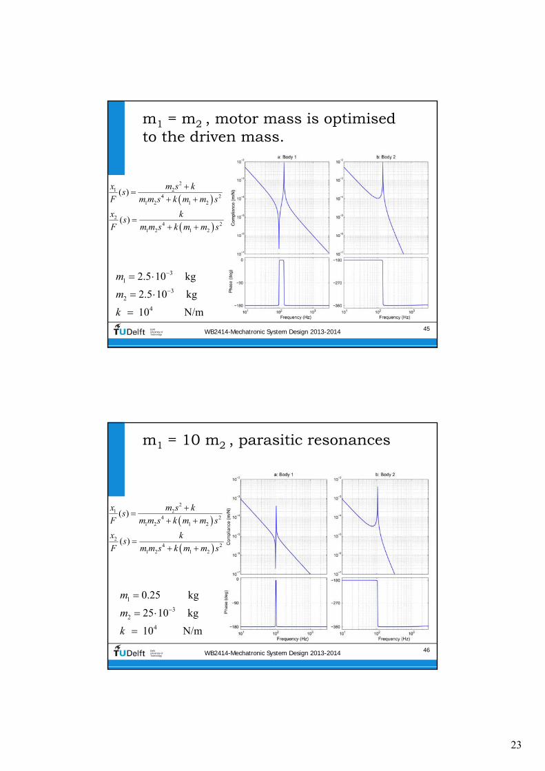
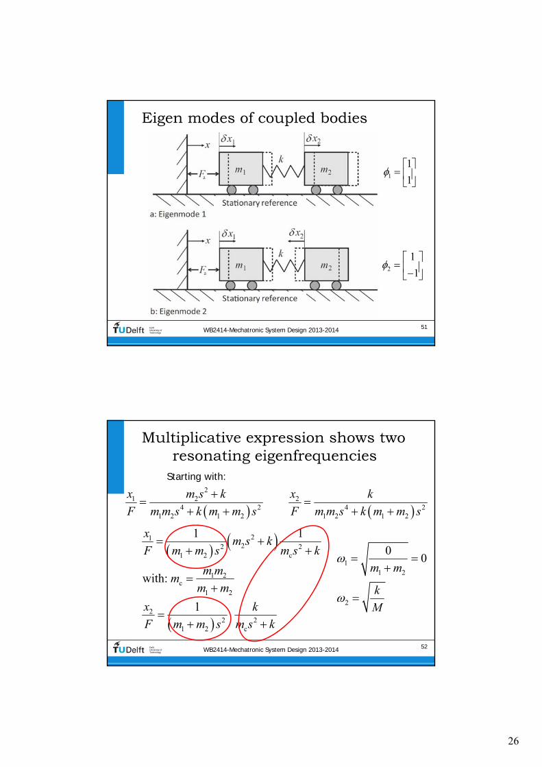
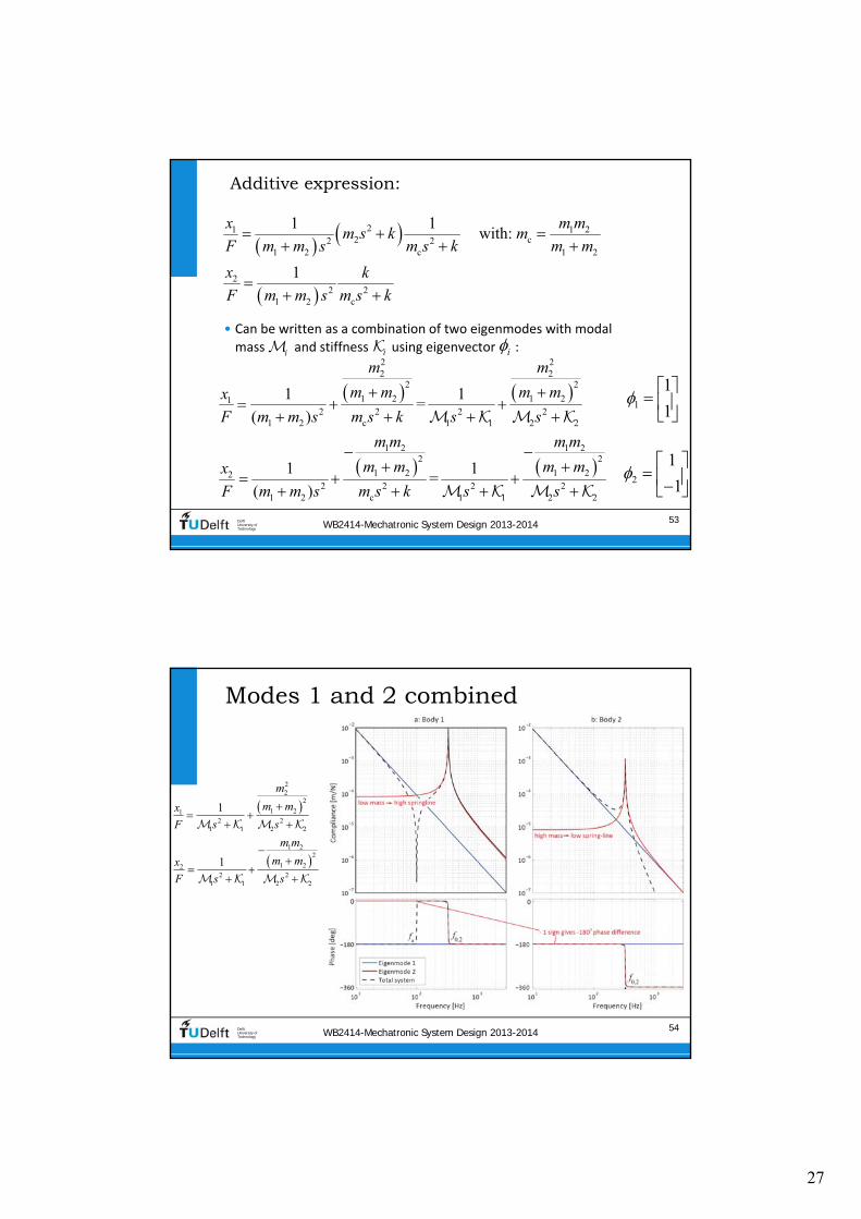
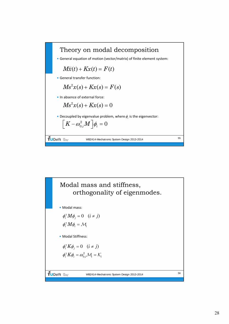
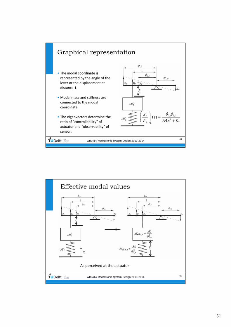
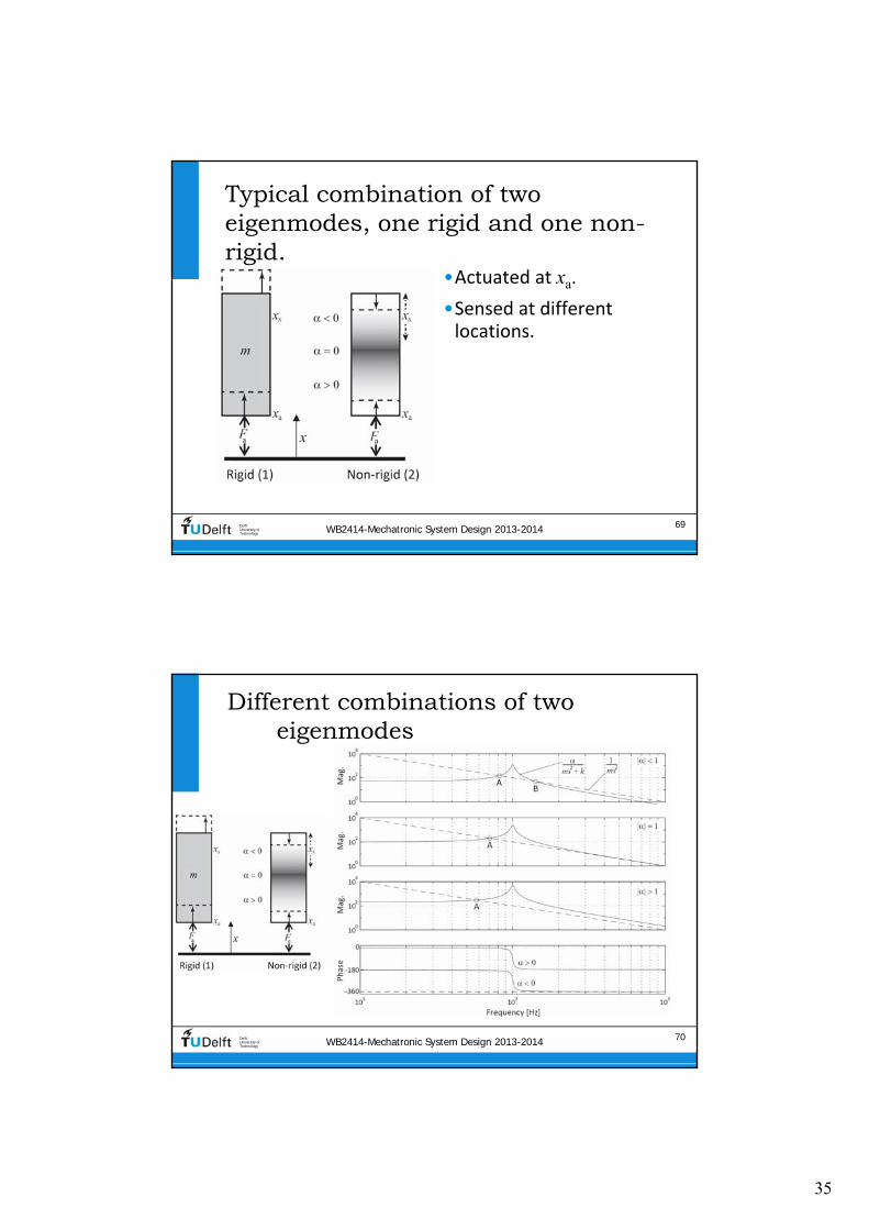

36
WB2414-Mechatronic System Design 2013-2014 71DelftUniversity ofTechnology
4 types of responses result
WB2414-Mechatronic System Design 2013-2014 72DelftUniversity ofTechnology
Eigenfrequencies of multiple eigenmodes in 6-DOF