MECHANISM OF FATIGUE CRACK INITIATION IN … · MECHANISM OF FATIGUE CRACK INITIATION IN AUSTENITIC...
10
MECHANISM OF FATIGUE CRACK INITIATION IN AUSTENITIC STAINLESS STEELS IN LWR ENVIRONMENTS Omesh K. Chopra Energy Technology Division, Argonne National Laboratory 9700 South Cass Avenue, Argonne, Illinois 60439 USA ABSTRACT This paper examines the mechanism of fatigue crack initiation in austenitic stainless steels (SSs) in light water reactor (LWR) coolant environments. The effects of key material and loading variables, such as strain amplitude, strain rate, temperature, level of dissolved oxygen in water, and material heat treatment on the fatigue lives of wrought and cast austenitic SSs in air and LWR environments have been evaluated. The influence of reactor coolant environments on the formation and growth of fatigue cracks in polished smooth SS specimens is discussed. Crack length as a function of fatigue cycles was determined in air and LWR environments. The results indicate that decreased fatigue lives of these steels are caused primarily by the effects of the environment on the growth of cracks <200 µm and, to a lesser extent, on enhanced growth rates of longer cracks. A detailed metallographic examination of fatigue test specimens was performed to characterize the fracture morphology. Exploratory fatigue tests were conducted to enhance our understanding of the effects of surface micropits or minor differences in the surface oxide on fatigue crack initiation. INTRODUCTION Existing fatigue strain–vs.–life (ε–N) data illustrate potentially significant effects of light water reactor (LWR) coolant environments on the fatigue resistance of carbon and low–alloy steels, 1-7 as well as of austenitic stainless steels (SS). 8-15 The key parameters that influence fatigue life in LWR environments are temperature; dissolved–oxygen (DO) level in water; strain rate; strain (or stress) amplitude; and, for carbon and low–alloy steels, sulfur content in the steel. Under certain environmental and loading conditions, fatigue lives of carbon steels can be a factor of 70 lower in coolant environments than in air. 3-5 For carbon and low–alloy steels, environmental effects on fatigue life are significant in high–DO water (>0.04 ppm DO) and only moderate (less than a factor of 2 decrease in life) in low–DO water. The reduction in fatigue life of carbon and low–alloy steels in LWR environments has been explained by the slip oxidation/dissolution mechanism for crack advance. 16 The requirements for the model are that a strain increment occur to rupture the protective surface oxide film and thereby expose the underlying matrix to the environment; once the passive oxide film is ruptured, crack extension is controlled by dissolution of freshly exposed surfaces and their oxidation characteristics. Unlike the case of carbon and low–alloy steels, environmental effects on the fatigue lives of austenitic SSs are significant in low–DO (i.e., <0.01 ppm DO) water; in high–DO water, environmental effects appear to be either comparable 12,13 or, in some cases, smaller 8 than those in low–DO water. These results are difficult to reconcile in terms of the slip oxidation/dissolution model. This paper examines the mechanism of fatigue crack initiation in austenitic SSs in LWR coolant environments. The effects of key material and loading variables on the fatigue lives of wrought and cast austenitic SSs in air and LWR environments have been evaluated. The influence of reactor coolant environments on the formation and growth of fatigue cracks in polished smooth specimens is discussed. Crack length as a function of fatigue cycles was determined in water by block loading that leaves beach marks on the fracture surface. Fatigue test specimens were examined to characterize the fracture morphology. Exploratory fatigue tests were conducted on austenitic SS specimens that were preexposed to either low– or high–DO water and then tested in air or water environments in an effort to understand the effects of surface micropits or minor differences in the surface oxide on fatigue crack initiation. FATIGUE ε–N BEHAVIOR Air Environment The existing fatigue ε–N data indicate that, in air, the fatigue lives of Types 304 and 316 SS are comparable; lives of Type 316NG are slightly higher at high strain amplitudes. 8-10 The fatigue ε–N behavior of cast CF-8 and CF–8M SS is similar to that of wrought austenitic SSs. Also, the fatigue life of austenitic SSs in air is independent of temperature in the range from room temperature to 427°C. 8,17 Although the effect of strain rate on fatigue life seems to be significant at temperatures above 400°C, variation in strain rate in the range of 0.4–0.008%/s has no effect on the fatigue lives of SSs at temperatures up to 400°C. 18 The cyclic stress vs. strain curves for Types 304, 316, and 316NG SS at room temperature and 288°C have been presented elsewhere. 8 During cyclic loading, austenitic SSs exhibit rapid hardening within the first 50–100 cycles; the extent of
-
Upload
truonghanh -
Category
Documents
-
view
223 -
download
0
Transcript of MECHANISM OF FATIGUE CRACK INITIATION IN … · MECHANISM OF FATIGUE CRACK INITIATION IN AUSTENITIC...

MECHANISM OF FATIGUE CRACK INITIATION IN
AUSTENITIC STAINLESS STEELS IN LWR ENVIRONMENTS
Omesh K. Chopra Energy Technology Division, Argonne National Laboratory
9700 South Cass Avenue, Argonne, Illinois 60439 USA
ABSTRACT This paper examines the mechanism of fatigue crack initiation in
austenitic stainless steels (SSs) in light water reactor (LWR) coolant environments. The effects of key material and loading variables, such as strain amplitude, strain rate, temperature, level of dissolved oxygen in water, and material heat treatment on the fatigue lives of wrought and cast austenitic SSs in air and LWR environments have been evaluated. The influence of reactor coolant environments on the formation and growth of fatigue cracks in polished smooth SS specimens is discussed. Crack length as a function of fatigue cycles was determined in air and LWR environments. The results indicate that decreased fatigue lives of these steels are caused primarily by the effects of the environment on the growth of cracks <200 µm and, to a lesser extent, on enhanced growth rates of longer cracks. A detailed metallographic examination of fatigue test specimens was performed to characterize the fracture morphology. Exploratory fatigue tests were conducted to enhance our understanding of the effects of surface micropits or minor differences in the surface oxide on fatigue crack initiation.
INTRODUCTION Existing fatigue strain–vs.–life (ε–N) data illustrate potentially
significant effects of light water reactor (LWR) coolant environments on the fatigue resistance of carbon and low–alloy steels,1-7 as well as of austenitic stainless steels (SS).8-15 The key parameters that influence fatigue life in LWR environments are temperature; dissolved–oxygen (DO) level in water; strain rate; strain (or stress) amplitude; and, for carbon and low–alloy steels, sulfur content in the steel. Under certain environmental and loading conditions, fatigue lives of carbon steels can be a factor of 70 lower in coolant environments than in air.3-5
For carbon and low–alloy steels, environmental effects on fatigue life are significant in high–DO water (>0.04 ppm DO) and only moderate (less than a factor of 2 decrease in life) in low–DO water. The reduction in fatigue life of carbon and low–alloy steels in LWR environments has been explained by the slip oxidation/dissolution mechanism for crack advance.16 The requirements for the model are that a strain increment occur to rupture the protective surface oxide film and thereby expose the underlying matrix to the environment;
once the passive oxide film is ruptured, crack extension is controlled by dissolution of freshly exposed surfaces and their oxidation characteristics. Unlike the case of carbon and low–alloy steels, environmental effects on the fatigue lives of austenitic SSs are significant in low–DO (i.e., <0.01 ppm DO) water; in high–DO water, environmental effects appear to be either comparable12,13 or, in some cases, smaller8 than those in low–DO water. These results are difficult to reconcile in terms of the slip oxidation/dissolution model.
This paper examines the mechanism of fatigue crack initiation in austenitic SSs in LWR coolant environments. The effects of key material and loading variables on the fatigue lives of wrought and cast austenitic SSs in air and LWR environments have been evaluated. The influence of reactor coolant environments on the formation and growth of fatigue cracks in polished smooth specimens is discussed. Crack length as a function of fatigue cycles was determined in water by block loading that leaves beach marks on the fracture surface. Fatigue test specimens were examined to characterize the fracture morphology. Exploratory fatigue tests were conducted on austenitic SS specimens that were preexposed to either low– or high–DO water and then tested in air or water environments in an effort to understand the effects of surface micropits or minor differences in the surface oxide on fatigue crack initiation.
FATIGUE ε–N BEHAVIOR Air Environment The existing fatigue ε–N data indicate that, in air, the fatigue
lives of Types 304 and 316 SS are comparable; lives of Type 316NG are slightly higher at high strain amplitudes.8-10 The fatigue ε–N behavior of cast CF-8 and CF–8M SS is similar to that of wrought austenitic SSs. Also, the fatigue life of austenitic SSs in air is independent of temperature in the range from room temperature to 427°C.8,17 Although the effect of strain rate on fatigue life seems to be significant at temperatures above 400°C, variation in strain rate in the range of 0.4–0.008%/s has no effect on the fatigue lives of SSs at temperatures up to 400°C.18 The cyclic stress vs. strain curves for Types 304, 316, and 316NG SS at room temperature and 288°C have been presented elsewhere.8 During cyclic loading, austenitic SSs exhibit rapid hardening within the first 50–100 cycles; the extent of

hardening increases with increasing strain amplitude, and decreasing temperature and strain rate.8,18 The initial hardening is followed by softening and a saturation stage at high temperatures, e.g., 288°C, and by continuous softening at room temperature.
LWR Environments The fatigue lives of austenitic SSs are decreased in LWR
environments; the reduction in life depends on strain amplitude, strain rate, temperature, and DO level in the water.8-15 The effects of LWR environments on fatigue lives of wrought materials are comparable for Types 304, 316, and 316NG SSs, whereas the effects on cast materials differ somewhat. The critical parameters that influence fatigue life and the threshold values that are required for environmental effects to be significant are summarized below.
Strain Amplitude: A minimum threshold strain is required for
environmentally–assisted decrease in fatigue lives of SSs to be significant. The threshold strain appears to be independent of material type (weld or base metal) and temperature in the range of 250–325°C, but it tends to decrease as the strain amplitude is decreased.14 The threshold strain appears to be related to the elastic strain range of the test and does not correspond to rupture strain of the surface oxide film. The fatigue life of a Type 304 SS specimen tested in low–DO water at 288°C with a 2–min hold period at zero strain during the tensile–rise portion of the cycle was identical with that of tests conducted under similar loading conditions but without the hold period.19 If this threshold strain corresponds to the rupture strain of the surface oxide film, a hold period at the middle of each cycle should allow repassivation of the oxide film, and environmental effects on fatigue life should diminish.
Loading Cycle: Environmental effects on fatigue life occur
primarily during the tensile–loading cycle and at strain levels greater than the threshold value. Consequently, loading and environmental conditions, e.g., strain rate, temperature, and DO level, during the tensile–loading cycle are important for environmentally–assisted reduction of fatigue lives of these steels. Limited data indicate that hold periods during peak tensile or compressive strain have no effect on the fatigue life of austenitic SSs in high–DO water. The fatigue lives of Type 304 SS tested with a trapezoidal waveform20 are comparable to those tested with a triangular waveform.8,15
Dissolved Oxygen in Water: The fatigue lives of austenitic SSs
are decreased significantly in low–DO (i.e., <0.01 ppm DO) water; the decrease in life is greater at low strain rates and high temperatures.8-15 Environmental effects on the fatigue lives of these steels in high–DO water appear to be either comparable to12,13 or, in some cases, smaller8 than those in low–DO water. Only moderate environmental effects (less than a factor of 2 decrease in life) were observed for a heat of Type 304 SS when conductivity of the water was maintained at <0.1 µS/cm and the electrochemical potential (ECP) of the steel was >150 mV (Fig. 1).19 The composition or heat treatment of the steel may have an important impact on the magnitude of environmental effects in high–DO environments. In low–DO water, the fatigue lives of cast SSs are comparable to those for wrought SSs.8,12,13 Limited data suggest that the fatigue lives of cast SSs in high–DO water are approximately the same as those in low–DO water.8 Additional data
are needed to get better insight into the effect of DO content on the fatigue life of austenitic SSs in LWR environments.
103 104 105 106
0.40.040.010.0040.0004
0.1
1.0
Type 304 SS289°C
Fatigue Life (Cycles)
Best–Fit AirStatistical Model
ε a (%
)
Dissolved Oxygen (ppm)Open Symbols: -0.8Closed Symbols: <0.005
Strain Rate (%/s)
Figure 1. Fatigue life of Type 304 stainless steel in low– and high–
DO water at 289°C (Ref. 19) Strain Rate: Fatigue life decreases with decreasing strain rate. In
low–DO pressurized water reactor (PWR) environments, fatigue life decreases logarithmically with decreasing strain rate below ≈0.4%/s; the effect of environment on life saturates at ≈0.0004%/s.8-15 Only a moderate decrease in life is observed at strain rates >0.4%/s. A decrease in strain rate from 0.4 to 0.0004%/s decreases the fatigue life of austenitic SSs by a factor of ≈10. For some SSs, the effect of strain rate may be less pronounced in high–DO water than in low–DO water. For cast SSs, the effect of strain rate on fatigue life is the same in low– and high–DO water and are comparable to that observed for the wrought SSs in low–DO water.12,13
Temperature: The results suggest a threshold temperature of
150°C, above which the environment decreases fatigue life in low–DO water if the strain rate is below the threshold of 0.4%/s.15,21 In the range of 150–325°C, the logarithm of fatigue life decreases linearly with temperature. Only a moderate decrease in life is observed in water at temperatures below the threshold value of 150°C.
Sensitization Anneal: In low–DO water, a sensitization anneal has
no effect on the fatigue life of Types 304 and 316 SS, whereas, in high–DO water, environmental effects are enhanced in sensitized steel. For example, the fatigue life of sensitized steel is a factor of ≈2 lower than that of solution–annealed material in high–DO water.12,13 Sensitization has little or no effect on the fatigue life of Type 316NG SS in low– and high–DO water.
Flow Rate: The effects of flow rate on the fatigue life of
austenitic SSs have not been investigated. The data for carbon steels indicate that, under the environmental conditions typical of operating boiling water reactors (BWRs), environmental effects on the fatigue life of carbon steels are a factor of ≈2 lower at high flow rates (7 m/s) than at 0.3 m/s or lower.22,23 Because the mechanism of fatigue crack initiation in LWR environments appears to be different in austenitic

SSs than in carbon steels, the effect of flow rate on fatigue life may also be different.
MECHANISM OF FATIGUE CRACK INITIATION Formation of Engineering–Size Cracks The formation of surface cracks and their growth to an
“engineering” size (3 mm deep) constitute the fatigue life of a material, which is represented by the fatigue ε–N curves. Fatigue life has conventionally been divided into two stages: initiation, expressed as the cycles required to form microcracks on the surface; and propagation, expressed as cycles required to propagate the surface cracks to engineering size. During cyclic loading of smooth test specimens, surface cracks 10 µm or longer form quite early in life (i.e., <10% of life) at surface irregularities or discontinuities either already in existence or produced by slip bands, grain boundaries, second–phase particles, etc.3,24–28 Consequently, fatigue life may be considered to be composed entirely of propagation of cracks from 10 to 3000 µm long.29
A schematic illustration of the two stages, i.e., initiation and propagation, of fatigue life is shown in Fig. 2. The initiation stage involves growth of microstructurally small cracks (MSCs), characterized by decelerating crack growth (Region AB in Fig. 2a). The propagation stage involves growth of mechanically small cracks, characterized by accelerating crack growth (Region BC in Fig. 2a). The growth of MSCs is very sensitive to microstructure.25,26 Fatigue cracks greater than the critical length of MSCs show little or no influence of microstructure, and are termed mechanically small cracks. Mechanically small cracks correspond to Stage II (tensile) cracks, which are characterized by striated crack growth, with a fracture surface normal to the maximum principal stress.
Once a microcrack forms on the surface, it continues to grow along its slip plane as a Mode II (shear) crack in Stage I growth (orientation of the crack is usually at 45° to the stress axis). At low strain amplitudes, a Stage I crack may extend across several grain diameters before the increasing stress intensity of the crack promotes slip on systems other than the primary slip system. A dislocation cell structure normally forms at the crack tip. Because slip is no longer confined to planes at 45° to the stress axis, the crack begins to propagate as a Mode I (tensile) crack, normal to the stress axis in Stage II growth. At high strain amplitudes, the stress intensity is quite large and the crack propagates entirely by the Stage II process. Stage II continues until the crack reaches engineering size (≈3 mm deep).
Various criteria have been used to define the crack length for transition from MSC to mechanically small crack; they may be related to the plastic zone size, crack–length–vs.–fatigue–life curve, Weibull distribution of the cumulative probability of fracture, stress–range– vs.–crack–length curve, or grain size. These criteria, summarized in Ref. 19, indicate that the transition crack length is a function of applied stress and microstructure of the material; actual values may range from 150 to 250 µm.
At low stress levels, e.g., ∆σ1 in Fig. 2, the transition from MSC growth to accelerating crack growth does not occur. This circumstance represents the fatigue limit for the smooth specimen. Although cracks can form below the fatigue limit, they can grow to engineering size only at stresses greater than the fatigue limit.
However, cracks larger than the transition crack length, either preexisting, e.g., defects in welded samples, or those created by growth of MSCs at high stresses, can grow at stress levels below the fatigue limit, and their growth can be estimated from linear–elastic or elastic–plastic fracture mechanics. The characterization and understanding of both the initiation stage and propagation stage are important for accurate estimates of the fatigue lives of structural mate ials. r
0 0.2 0.4 0.6 0.8 1
Cra
ck L
engt
h
Life Fraction
Microstructurally Small Crack (MSC)(Stage–I Shear Crack)
Mechanically Small Crack(Stage II Tensile Crack)
A
B
C
∆σ2
∆σ1
∆σ2 > ∆σ1
(a)
Crack Length
MSC
LEFM
∆σ 1
Non–PropagatingCracks
Short Cracks
∆σ 3
∆σ 2
∆σ 3 > ∆σ 2 > ∆σ 1
∆σ 1
(b)
Figure 2. Schematic illustration of (a) growth of short cracks in smooth specimens as a function of fatigue life fraction and
(b) crack velocity as a function of crack length. LEFM = linear elastic fracture mechanics; MSC =
microstructurally small cracks. Growth Rates of Small Cracks in LWR Environments The reduction in fatigue life of structural materials in LWR
coolant environments has often been attributed to easy crack formation. Measurements of crack frequency, i.e., number of cracks per unit length of the specimen gauge surface, indicate that, under similar loading conditions, the number of cracks in specimens tested in air and low–DO water are comparable, although fatigue life is significantly lower in low–DO water. For Type 316NG SS tested at 288°C, ≈0.75% strain range, and 0.005%/s strain rate, the number of cracks (longer than 20 µm) along a 7–mm gauge length was 16, 14, and 8 in air, simulated PWR (low–DO) water, and high–DO water, respectively.9 If reduction in life is caused by easy crack formation,

specimens tested in water should contain more cracks. Also, as discussed above, several studies indicate that fatigue cracks, 10 µm or longer, form quite early in life, i.e., <10% of life. Therefore, at most, easy crack formation can decrease fatigue life by 10%. The reduction in fatigue life in LWR coolant environments most likely arises from an increase in crack growth rates (CGRs) during either the initiation stage (i.e., growth of MSCs), and/or the propagation stage (i.e., growth of mechanically small cracks).
101
102
103
104
105
103 104 105 106
PWRBWRAirAir (calc)
Air
Cra
ck D
epth
(µm
)
Number of Cycles
Type 304 SS, 288oC, Strain Range: 0.75%
Type 316L SS, 25oC, Strain Range: 0.2%
Figure 3. Depth of largest crack plotted as a function of fatigue cycles for austenitic stainless steels in air and water (Refs. 27,30)
Figure 3 shows the depth of the largest crack observed in
austenitic SSs in air and water environments as a function of fatigue cycles.30 In the figure, the crack length for the test in air at 288°C and 0.75% strain range was measured only near the end of the test. The data obtained by Orbtlik et al.27 on Type 316L SS in air at 25°C and ≈0.2% strain range were used to estimate the crack growth in air at 0.75% strain range. Studies on carbon and low-alloy steels25,26,31 indicate that the fatigue crack size at various life fractions is independent of strain range, strain rate, and temperature; consequently, the depth of the largest crack at various life fractions is approximately the same at 0.75 and 0.2% strain ranges. The curve for the test in air at 0.75% (shown as a dash line in Fig. 3) was calculated from the best-fit equation of the experimental data for Type 316L SS at 0.2% strain range; the estimated crack lengths at 0.75% strain range show very good agreement with the measured values. The results show that at the same number of cycles, the crack length is longer in low–DO water than in air, e.g., after 1500 cycles the crack length in air, high-DO (BWR) water, and low–DO (PWR) water is ≈40, 300, and 1100 µm, respectively (Fig. 3). The growth of cracks during the initiation stage, i.e., growth of MSCs, is enhanced in water; fatigue cycles needed to form a 500–µm crack are a factor of ≈12 lower in low–DO water than in air. Figure 3 shows that the number of cycles required to produce a 500–µm crack is 800, 3000, and 9,000 in low–DO (PWR), high-DO (BWR), and air environments, respectively; thus the number of cycles is more than a factor of 10 lower in low–DO water than in air.
The CGRs during the propagation stage, i.e., growth of mechanically small cracks, in air and water environments are plotted as a function of crack length in Fig. 4; they were calculated from the best–fit of the data in Fig. 3. The CGRs in high–DO water for the
specimen with a 24–h soak period (closed circles in Fig. 4) were determined from measurements of fatigue striations on the fracture surface. The CGRs are a factor of 2–6 higher in water than in air. Growth rates in PWR water or high–DO water with a 24–h soak period are higher than those in high–DO water with a 120–h soak period. At a crack length of ≈1000 µm, the CGRs in air, high–DO water, and low–DO PWR environment are 0.30, 0.64, and 1.05 µm/cycle, respectively. For the 0.75% strain range and 0.004%/s strain rate, these values correspond to growth rates of ≈1.6 x 10⁻⁹, 3.4 x 10⁻⁹, and 5.6 x 10⁻⁹ m/s in air, high–DO water, and low–DO water, respectively. Growth rates are a factor of 3.5 greater in low–DO water than in air.
10-1
100
101
102 103 104
PWRHigh–DO WaterAir (Estimated)
Cra
ck G
row
th R
ate
(µm
/Cyc
le)
Crack Length (µm)
Type 304 SS 288°C Strain Range: 0.75%Strain Rate: 0.004%/s
Open Circles: 120-SoakClosed Circles: 24-h Soak
10-4
10-3
10-2
10-1
100
101 102 103 104
0.75%0.24%
0.20%
Cra
ck G
row
th R
ate
(µm
/Cyc
le)
Crack Length (µm)
Austenitic SSAir
Strain RangeType 304 SS 288°C
Type 316L SS 25°C
Estimated
Figure 4. Crack growth rates plotted as a function of crack length
for stainless steels in air and water environments (Refs. 27,30) The CGR data obtained from fracture–mechanics tests indicate
significant enhancement of growth rates in high–DO water,32 the rates under BWR normal water chemistry (NWC) exceed the air value in the ASME Code by a factor of ≈20–30. The CGR in water [ Ý a env (m/s)] with 0.2 ppm DO (i.e., BWR NWC) is expressed in terms of the CGR in air ( Ý a air ) by the relationship
Ý a env = Ý aira + 4.5 x 10⁻⁵ ( Ý a air )0.5. (1)
The CGR data from fracture–mechanics tests in low–DO PWR environments are sparse, particularly at rates that are <10–9 m/s. At high CGRs, the observed enhancement in both low– and high–DO environments is relatively small, and the magnitude of the enhancement under the same loading conditions is comparable in the two environments. Until further data become available at low CGRs in simulated PWR water, Shack and Kassner32 recommend that the environmental enhancement represented by Eq. 1 for 0.2 ppm DO water also be considered for PWR environments.
The CGRs determined from fatigue ε–N tests in water and air environments at 289°C are plotted in Fig. 5. The rates in high–DO and low–DO (PWR) water represent the measured values shown as open diamonds and circles, respectively, in Fig. 4. The CGRs in air for the same loading conditions (i.e., the same crack length) were determined from the estimated rates in air, shown by a solid line in Fig. 4. The CGRs determined from the ε–N tests in high–DO water are consistent with the trend predicted from Eq. 1; the rates in low–DO water are slightly higher. However, the large reductions in fatigue life of austenitic SSs in PWR environments cannot be explained entirely on the basis of enhanced CGRs during the propagation stage, i.e., growth of mechanically small cracks. For example, the CGRs in low–DO water are a factor of 1.6 greater than those in high–DO water, but the fatigue life is a factor of ≈4 lower in low–DO water than in high–DO water. As shown in Fig. 3, the decrease in fatigue lives of austenitic SSs in PWR environments is caused predominantly by the effects of environment on the growth of MSCs.
10-10
10-9
10-8
10-10 10-9 10-8
PWR WaterHigh-DO Water
CG
R env
(m/s
)
CGRair (m/s)
Type 304 SS289°C
CGRenv = CGRair + 4.5x10⁻⁵( CGRair)0.5
Figure 5. Crack growth rate data for Type 304 SS determined from fatigue ε–N tests in PWR and high–DO water at 289°C
It should also be noted that, if enhanced CGRs alone were
responsible for the environmentally–assisted decrease in fatigue life of materials in LWR environments, environmental effects on the fatigue lives of Alloy 600 and austenitic SSs in LWR environments should be comparable. In air, the fatigue ε–N behavior of Alloy 600 is comparable to that of austenitic SSs.17 Fatigue CGR data indicate that the enhancement of CGRs of Alloy 600 and austenitic SSs in LWR environments is also comparable.33 However, the fatigue ε–N
behaviors of Alloy 600 and austenitic SSs in water differ significantly; only moderate effects of environment are observed for Alloy 600 and its weld both in low– and high–DO water.34,35 For example, the fatigue life of Alloy 600 weld metal in water with <0.005 ppm DO at 325°C and 0.6% strain amplitude decreased by a factor of ≈2.5 when the strain rate was decreased from 0.4 to 0.001%/s.34 Under similar environmental and loading conditions, the fatigue life of austenitic SSs is decreased by a factor of ≈10.
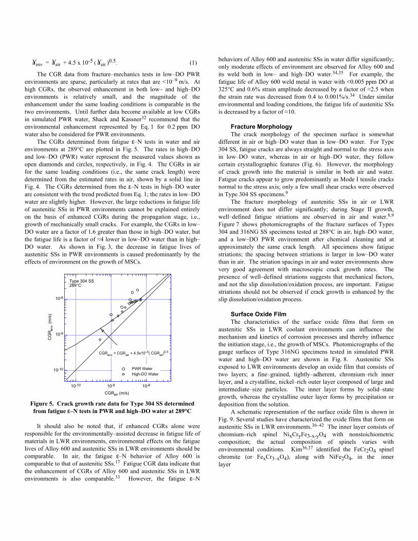
Fracture Morphology The crack morphology of the specimen surface is somewhat
different in air or high–DO water than in low–DO water. For Type 304 SS, fatigue cracks are always straight and normal to the stress axis in low–DO water, whereas in air or high–DO water, they follow certain crystallographic features (Fig. 6). However, the morphology of crack growth into the material is similar in both air and water. Fatigue cracks appear to grow predominantly as Mode I tensile cracks normal to the stress axis; only a few small shear cracks were observed in Type 304 SS specimens.9
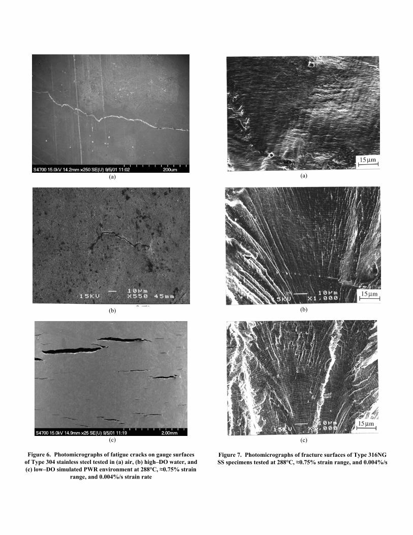
The fracture morphology of austenitic SSs in air or LWR environment does not differ significantly; during Stage II growth, well–defined fatigue striations are observed in air and water.8,9 Figure 7 shows photomicrographs of the fracture surfaces of Types 304 and 316NG SS specimens tested at 288°C in air, high–DO water, and a low–DO PWR environment after chemical cleaning and at approximately the same crack length. All specimens show fatigue striations; the spacing between striations is larger in low–DO water than in air. The striation spacings in air and water environments show very good agreement with macroscopic crack growth rates. The presence of well–defined striations suggests that mechanical factors, and not the slip dissolution/oxidation process, are important. Fatigue striations should not be observed if crack growth is enhanced by the slip dissolution/oxidation process.
Surface Oxide Film The characteristics of the surface oxide films that form on
austenitic SSs in LWR coolant environments can influence the mechanism and kinetics of corrosion processes and thereby influence the initiation stage, i.e., the growth of MSCs. Photomicrographs of the gauge surfaces of Type 316NG specimens tested in simulated PWR water and high–DO water are shown in Fig. 8. Austenitic SSs exposed to LWR environments develop an oxide film that consists of two layers; a fine–grained, tightly–adherent, chromium–rich inner layer, and a crystalline, nickel–rich outer layer composed of large and intermediate–size particles. The inner layer forms by solid–state growth, whereas the crystalline outer layer forms by precipitation or deposition from the solution.
A schematic representation of the surface oxide film is shown in Fig. 9. Several studies have characterized the oxide films that form on austenitic SSs in LWR environments.36–42 The inner layer consists of chromium–rich spinel NixCryFe3-x-yO4 with nonstoichiometric composition; the actual composition of spinels varies with environmental conditions. Kim36,37 identified the FeCr2O4 spinel chromite (or FexCr3–xO4), along with NiFe2O4, in the inner layer
(a)
(b)
(c)
Figure 6. Photomicrographs of fatigue cracks on gauge surfaces of Type 304 stainless steel tested in (a) air, (b) high–DO water, and (c) low–DO simulated PWR environment at 288°C, ≈0.75% strain
range, and 0.004%/s strain rate
(a)
(b)
(c)
Figure 7. Photomicrographs of fracture surfaces of Type 316NG SS specimens tested at 288°C, ≈0.75% strain range, and 0.004%/s

strain rate in (a) air, (b) high–DO water, and (c) low–DO simulated PWR water (Refs. 8,9)
(a)
(b)
Figure 8. Photomicrographs of oxide films that formed on Type 316NG stainless steel in (a) simulated PWR water and (b) high–
DO water (Ref. 9) formed on Types 304 and 316 SS exposed at 288°C under conditions of NWC or hydrogen water chemistry (HWC). Kim also noted that the inner oxide layer formed in a NWC BWR environment contains a lower concentration of chromium than that formed in a HWC low–DO
environment. Such differences have been attributed to chromium oxidation in high–DO water.
The structure and composition of the crystalline outer layer vary with the water chemistry. In BWR environments, the large particles in the outer layer are primarily composed of α—Fe2O3 hematite in NWC, and Fe3O4 magnetite in HWC.36,37 The intermediate particles in the outer layer are composed of α—Fe2O3 in NWC and FeCr2O4 in HWC. The structure of the outer layer varies when the water chemistry is cycled between NWC and HWC. In PWR environments, the large particles have been identified as Ni0.75Fe2.25O4 spinel and the intermediate particles as Ni0.75Fe2.25O4 + Fe3O4.40 The possible effect of minor differences in the surface oxide film on fatigue crack initiation is discussed in the next section.
Stainless Steel Substrate
Large-size ParticlesOuter Layer
Intermediate-size ParticlesOuter Layer
Fine-grained Inner Layer
Figure 9. Schematic of corrosion oxide film formed on austenitic stainless steels in LWR environments
Exploratory Fatigue Tests The reduction of fatigue life in high–temperature water has often
been attributed to the presence of surface micropits that are formed in high–temperature water and may act as stress raisers and provide preferred sites for the formation of fatigue cracks. In an effort to understand the effects of surface micropits or minor differences in the surface oxide film on fatigue crack initiation, fatigue tests were conducted on Type 316NG (Heat P91576) specimens that were preexposed to either low– or high–DO water and then tested in air or water environments. The results of these tests, and data obtained earlier on this heat and Heat D432804 of Type 316NG SS in air and low–DO water at 288°C, are given in Table 1; the results are plotted in Fig. 10.
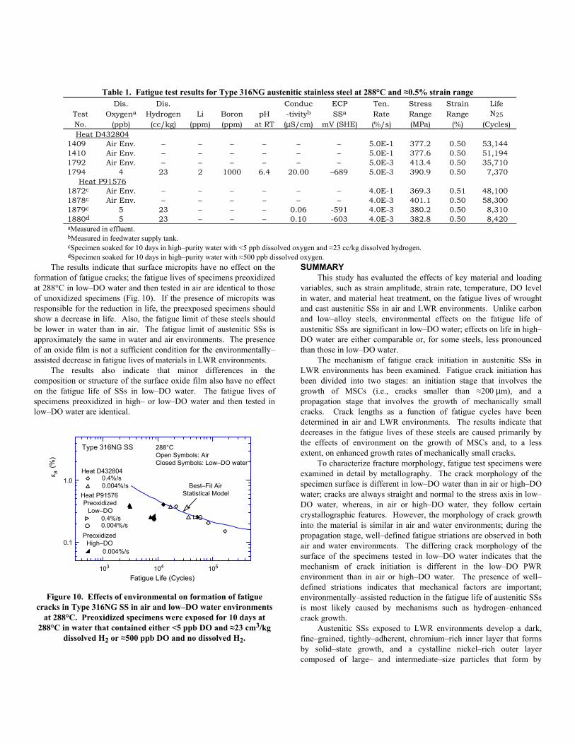
SUMMARY The results indicate that surface micropits have no effect on the formation of fatigue cracks; the fatigue lives of specimens preoxidized at 288°C in low–DO water and then tested in air are identical to those of unoxidized specimens (Fig. 10). If the presence of micropits was responsible for the reduction in life, the preexposed specimens should show a decrease in life. Also, the fatigue limit of these steels should be lower in water than in air. The fatigue limit of austenitic SSs is approximately the same in water and air environments. The presence of an oxide film is not a sufficient condition for the environmentally– assisted decrease in fatigue lives of materials in LWR environments.
Table 1. Fatigue test results for Type 316NG austenitic stainless steel at 288°C and ≈0.5% strain range
Test No.
Dis. Oxygena
(ppb)
Dis. Hydrogen
(cc/kg)
Li
(ppm)
Boron(ppm)
pH
at RT
Conduc-tivityb (µS/cm)
ECP SSa
mV (SHE)
Ten. Rate (%/s)
Stress Range (MPa)
Strain Range
(%)
Life N25
(Cycles) Heat D432804
1409 Air Env. – – – – – – 5.0E-1 377.2 0.50 53,144 1410 Air Env. – – – – – – 5.0E-1 377.6 0.50 51,194 1792 Air Env. – – – – – – 5.0E-3 413.4 0.50 35,710 1794 4 23 2 1000 6.4 20.00 –689 5.0E-3 390.9 0.50 7,370
Heat P91576 1872c Air Env. – – – – – – 4.0E-1 369.3 0.51 48,100 1878c Air Env. – – – – – – 4.0E-3 401.1 0.50 58,300 1879c 5 23 – – – 0.06 -591 4.0E-3 380.2 0.50 8,310 1880d 5 23 – – – 0.10 -603 4.0E-3 382.8 0.50 8,420 aMeasured in effluent. bMeasured in feedwater supply tank. cSpecimen soaked for 10 days in high–purity water with <5 ppb dissolved oxygen and ≈23 cc/kg dissolved hydrogen. dSpecimen soaked for 10 days in high–purity water with ≈500 ppb dissolved oxygen.
This study has evaluated the effects of key material and loading variables, such as strain amplitude, strain rate, temperature, DO level in water, and material heat treatment, on the fatigue lives of wrought and cast austenitic SSs in air and LWR environments. Unlike carbon and low–alloy steels, environmental effects on the fatigue life of austenitic SSs are significant in low–DO water; effects on life in high–DO water are either comparable or, for some steels, less pronounced than those in low–DO water.
The mechanism of fatigue crack initiation in austenitic SSs in LWR environments has been examined. Fatigue crack initiation has been divided into two stages: an initiation stage that involves the growth of MSCs (i.e., cracks smaller than ≈200 µm), and a propagation stage that involves the growth of mechanically small cracks. Crack lengths as a function of fatigue cycles have been determined in air and LWR environments. The results indicate that decreases in the fatigue lives of these steels are caused primarily by the effects of environment on the growth of MSCs and, to a less extent, on enhanced growth rates of mechanically small cracks.
The results also indicate that minor differences in the composition or structure of the surface oxide film also have no effect on the fatigue life of SSs in low–DO water. The fatigue lives of specimens preoxidized in high– or low–DO water and then tested in low–DO water are identical.
103 104 105
0.4%/s0.004%/s
0.4%/s0.004%/s
0.004%/s0.1
1.0
Type 316NG SS
Fatigue Life (Cycles)
Best–Fit AirStatistical Model
ε a (%
)
288°COpen Symbols: AirClosed Symbols: Low–DO water
Heat D432804
Heat P91576 Preoxidized
Low–DO
PreoxidizedHigh–DO
To characterize fracture morphology, fatigue test specimens were examined in detail by metallography. The crack morphology of the specimen surface is different in low–DO water than in air or high–DO water; cracks are always straight and normal to the stress axis in low–DO water, whereas, in air or high–DO water, they follow certain crystallographic features. However, the morphology of crack growth into the material is similar in air and water environments; during the propagation stage, well–defined fatigue striations are observed in both air and water environments. The differing crack morphology of the surface of the specimens tested in low–DO water indicates that the mechanism of crack initiation is different in the low–DO PWR environment than in air or high–DO water. The presence of well–defined striations indicates that mechanical factors are important; environmentally–assisted reduction in the fatigue life of austenitic SSs is most likely caused by mechanisms such as hydrogen–enhanced crack growth.
Figure 10. Effects of environmental on formation of fatigue cracks in Type 316NG SS in air and low–DO water environments
at 288°C. Preoxidized specimens were exposed for 10 days at 288°C in water that contained either <5 ppb DO and ≈23 cm3/kg
dissolved H2 or ≈500 ppb DO and no dissolved H2. Austenitic SSs exposed to LWR environments develop a dark,
fine–grained, tightly–adherent, chromium–rich inner layer that forms by solid–state growth, and a cystalline nickel–rich outer layer composed of large– and intermediate–size particles that form by
precipitation or deposition from the solution. The characteristics of the surface oxide films can influence the mechanism and kinetics of corrosion processes and thereby influence fatigue crack initiation. Exploratory fatigue tests were conducted on austenitic SS specimens that were preexposed to either low– or high–DO water and then tested in air or water environments in and effort to understand the effects of surface micropits or minor differences in the surface oxide on fatigue crack initiation. The results indicate that the presence of a surface oxide film or any difference in the characteristics of the oxide film has no effect on fatigue crack initiation in austenitic SSs in LWR environments.
ACKNOWLEDGMENTS This work was sponsored by the Office of Nuclear Regulatory
Research, U.S. Nuclear Regulatory Commission, FIN Number W6610; Program Manager: Dr. Joe Muscara
REFERENCES 1. O. K. Chopra and W. J. Shack, Evaluation of Effects of LWR
Coolant Environments on Fatigue Life of Carbon and Low–Alloy Steels, in Effects of the Environment on the Initiation of Crack Growth, ASTM STP 1298, W. A. Van Der Sluys, R. S. Piascik, and R. Zawierucha, eds., American Society for Testing and Materials, Philadelphia, pp. 247–266 (1997).
2. O. K. Chopra and W. J. Shack, Low–Cycle Fatigue of Piping and Pressure Vessel Steels in LWR Environments, Nucl. Eng. Des. 184, 49–76 (1998).
3. O. K. Chopra and W. J. Shack, Effects of LWR Coolant Environments on Fatigue Design Curves of Carbon and Low–Alloy Steels, NUREG/CR–6583, ANL–97/18 (March 1998).
4. O. K. Chopra and W. J. Shack, Overview of Fatigue Crack Initiation in Carbon and Low–Alloy Steels in Light Water Reactor Environments, J. Pressure Vessel Technol. 121, 49–60 (1999).
5. M. Higuchi and K. Iida, Fatigue Strength Correction Factors for Carbon and Low–Alloy Steels in Oxygen–Containing High–Temperature Water, Nucl. Eng. Des. 129, 293–306 (1991).
6. G. Nakao, H. Kanasaki, M. Higuchi, K. Iida, and Y. Asada, Effects of Temperature and Dissolved Oxygen Content on Fatigue Life of Carbon and Low–Alloy Steels in LWR Water Environment, in Fatigue and Crack Growth: Environmental Effects, Modeling Studies, and Design Considerations, PVP Vol. 306, S. Yukawa, ed., American Society of Mechanical Engineers, New York, pp. 123–128 (1995).
7. M. Higuchi, K. Iida, and Y. Asada, Effects of Strain Rate Change on Fatigue Life of Carbon Steel in High–Temperature Water, in Effects of the Environment on the Initiation of Crack Growth, ASTM STP 1298, W. A. Van Der Sluys, R. S. Piascik, and R. Zawierucha, eds., American Society for Testing and Materials, Philadelphia, pp. 216–231 (1997).
8. O. K. Chopra, Effects of LWR Coolant Environments on Fatigue Design Curves of Austenitic Stainless Steels, NUREG/CR–5704, ANL–98/31 (1999).
9. O. K. Chopra and D. J. Gavenda, Effects of LWR Coolant Environments on Fatigue Lives of Austenitic Stainless Steels, J. Pressure Vessel Technol. 120, 116–121 (1998).
10. O. K. Chopra and J. L. Smith, Estimation of Fatigue Strain–Life Curves for Austenitic Stainless Steels in Light Water Reactor Environments, in Fatigue, Environmental Factors, and New Materials, PVP Vol. 374, H. S. Mehta, R. W. Swindeman, J. A. Todd, S. Yukawa, M. Zako, W. H. Bamford, M. Higuchi, E. Jones, H. Nickel, and S. Rahman, eds., American Society of Mechanical Engineers, New York, pp. 249–259 (1998).
11. M. Fujiwara, T. Endo, and H. Kanasaki, Strain Rate Effects on the Low–Cycle Fatigue Strength of 304 Stainless Steel in High–Temperature Water Environment; Fatigue Life: Analysis and Prediction, in Proc. Intl. Conf. and Exposition on Fatigue, Corrosion Cracking, Fracture Mechanics, and Failure Analysis, ASM, Metals Park, OH, pp. 309–313 (1986).
12. H. Kanasaki, R. Umehara, H. Mizuta, and T. Suyama, Fatigue Lives of Stainless Steels in PWR Primary Water, Trans. 14th Intl. Conf. on Structural Mechanics in Reactor Technology (SMiRT 14), Lyon, France, pp. 473–483 (1997).
13. K. Tsutsumi, H. Kanasaki, T. Umakoshi, T. Nakamura, S. Urata, H. Mizuta, and S. Nomoto, Fatigue Life Reduction in PWR Water Environment for Stainless Steels, in Assessment Methodologies for Preventing Failure: Service Experience and Environmental Considerations, PVP Vol. 410-2, R. Mohan, ed., American Society of Mechanical Engineers, New York, pp. 23–34 (2000).
14. K. Tsutsumi, T. Dodo, H. Kanasaki, S. Nomoto, Y. Minami, and T. Nakamura, Fatigue Behavior of Stainless Steel under Conditions of Changing Strain Rate in PWR Primary Water, in Pressure Vessel and Piping Codes and Standards, PVP Vol. 419, M. D. Rana, ed., American Society of Mechanical Engineers, New York, pp. 135–141 (2001).
15. M. Higuchi and K. Iida, Reduction in Low–Cycle Fatigue Life of Austenitic Stainless Steels in High–Temperature Water, in Pressure Vessel and Piping Codes and Standards, PVP Vol. 353, D. P. Jones, B. R. Newton, W. J. O'Donnell, R. Vecchio, G. A. Antaki, D. Bhavani, N. G. Cofie, and G. L. Hollinger, eds., American Society of Mechanical Engineers, New York, pp. 79–86 (1997).
16. F. P. Ford, Prediction of Corrosion–Fatigue Initiation in Low–Alloy Steel and Carbon Steel/Water Systems at 288°C, in Proc. of the Sixth Intl. Symp. on Environmental Degradation of Materials in Nuclear Power Systems-Water Reactors, R. E. Gold and E. P. Simonen, eds., The Minerals, Metals, and Materials Society, Warrendale, PA, pp. 9-17 (1993).
17. C. E. Jaske and W. J. O’Donnell, Fatigue Design Criteria for Pressure Vessel Alloys, Trans. ASME J. Pressure Vessel Technol. 99, 584–592 (1977).
18. C. Amzallag, P. Rabbe, G. Gallet, H. –P. Lieurade, Influence des Conditions de Sollicitation Sur le Comportement en Fatigue Oligocyclique D'aciers Inoxydables Austénitiques, Memoires Scientifiques Revue Metallurgie, French Metallurgy Society, pp. 161–173 (1978).
19. O. K. Chopra and W. J. Shack, Environmental Effects on Fatigue Crack Initiation in Piping and Pressure Vessel Steels, NUREG/CR–6717, ANL–00/27 (May 2001).
20. D. A. Hale, S. A. Wilson, E. Kiss, and A. J. Gianuzzi, Low Cycle Fatigue Evaluation of Primary Piping Materials in a BWR Environment, GEAP–20244, U.S. Nuclear Regulatory Commission (Sept. 1977).

21. K. Iida, T. Bannai, M. Higuchi, K. Tsutsumi, and K. Sakaguchi, Comparison of Japanese MITI Guideline and Other Methods for Evaluation of Environmental Fatigue Life Reduction, in Pressure Vessel and Piping Codes and Standards, PVP Vol. 419, M. D. Rana, ed., American Society of Mechanical Engineers, New York, pp. 73–81 (2001).
22. A. Hirano, M. Yamamoto, K. Sakaguchi, K. Iida, and T. Shoji, Effects of Water Flow Rate on Fatigue Life of Carbon Steel in High–Temperature Pure Water Environment, in Assessment Methodologies for Predicting Failure: Service Experience and Environmental Considerations, PVP Vol. 410–2, R. Mohan, ed., American Society of Mechanical Engineers, New York, pp. 13–18 (2000).
23. E. Lenz, N. Wieling, and H. Muenster, Influence of Variation of Flow Rates and Temperature on the Cyclic Crack Growth Rate under BWR Conditions, in Environmental Degradation of Materials in Nuclear Power Systems – Water Reactors, The Metallurgical Society, Warrendale, PA (1988).
24. K. J Miller, Initiation and Growth Rates of Short Fatigue Cracks, Fundamentals of Deformation and Fracture, Eshelby Memorial Symposium, Cambridge University Press, Cambridge, U.K., pp. 477–500 (1985).
25. K. Tokaji, T. Ogawa, and S. Osaka, The Growth of Microstructurally Small Fatigue Cracks in a Ferrite–Pearlite Steel, Fatigue Fract. Eng. Mater. Struct. 11, 311–342 (1988).
26. D. J. Gavenda, P. R. Luebbers, and O. K. Chopra, Crack Initiation and Crack Growth Behavior of Carbon and Low–Alloy Steels, in Fatigue and Fracture 1, Vol. 350, S. Rahman, K. K. Yoon, S. Bhandari, R. Warke, and J. M. Bloom, eds., American Society of Mechanical Engineers, New York, pp. 243–255 (1997).
27. K. Obrtlik, J. Polák, M. Hájek, and A. Vasek, Short Fatigue Crack Behaviour in 316L Stainless Steel, Intl. J. Fatigue 19, 471–475 (1997).
28. S. G. Sundara Raman, D. Argence, and A. Pineau, High Temperature Short Fatigue Crack Behaviour in a Stainless Steel, Fatigue Fract. Eng. Mater. Struct. 20, 1015–1031 (1997).
29. K. J. Miller, Damage in Fatigue: A New Outlook, in International Pressure Vessels and Piping Codes and Standards: Volume 1 – Current Applications, PVP Vol. 313–1, K. R. Rao and Y. Asada, eds., American Society of Mechanical Engineers, New York, pp. 191–192 (1995).
30. J. L. Smith, and O. K. Chopra, Crack Initiation in Smooth Fatigue Specimens of Austenitic Stainless Steel in Light Water Reactor Environments, in Operations, Applications, and Components – 1999, PVP Vol. 395, I. T. Kisisel, ed., American Society of Mechanical Engineers, New York, pp. 235–242 (1999).
31. C. M. Suh, R. Yuuki, and H. Kitagawa, Fatigue Microcracks in a Low Carbon Steel, Fatigue Fract. Eng. Mater. Struct. 8, 193-203 (1985).
32. W. J. Shack and T. F. Kassner, Review of Environmental Effects on Fatigue Crack Growth of Austenitic Stainless Steels, NUREG/CR–6176, ANL–94/1 (May 1994).
33. O. K. Chopra, W. K. Soppet, and W. J. Shack, Effects of Alloy Chemistry, Cold Work, and Water Chemistry on Corrosion Fatigue and Stress Corrosion Cracking of Nickel Alloys and Welds, NUREG/CR–6721, ANL–01/07 (April 2001).
34. H. Kanasaki, Fatigue Life of Stainless Steels and Alloy 600 in PWR Environments, presented at the PVRC Autumn Meeting of the Working Group on S–N Data, October 7–9, 1996, Columbus, OH.
35. J. Keisler, O. K. Chopra, and W. J. Shack, Statistical Models for Estimating Fatigue Strain–Life Behavior of Pressure Boundary Materials in Light Water Reactor Environments, Nucl. Eng. Des. 167, 129–154 (1996).
36. Y. J. Kim, Characterization of the Oxide Film Formed on Type 316 Stainless Steel in 288°C Water in Cyclic Normal and Hydrogen Water Chemistries, Corrosion 51 (11), 849–860 (1995).
37. Y. J. Kim, Analysis of Oxide Film Formed on Type 304 Stainless Steel in 288°C Water Containing Oxygen, Hydrogen, and Hydrogen Peroxide, Corrosion 55 (1), 81–88 (1999).
38. R. L. Tapping, R. D. Davidson, E. McAlpine, and D. H. Lister, The Composition and Morphology of Oxide Films Formed on Type 304 Stainless Steel in Lithiated High–Temperature Water, Corrosion Sci. 26 (8), 563–576 (1986).
39. D. H. Lister, R. D. Davidson, and E. McAlpine, The Mechanism and Kinetics of Corrosion Product Release from Stainless Steel in Lithiated High–Temperature Water, Corrosion Sci. 27 (2), 113–140 (1987).
40. M. Da Cunha Belo, M. Walls, N. E. Hakiki, J. Corset, E. Picquenard, G. Sagon, and D. Neol, Composition, Structure and Properties of the Oxide Films Formed on the Stainless Steel 316L in a Primary Type PWR Environment, Corrosion Sci. 40 (2/3), 447–463 (1998).
41. B. Stellwag, The Mechanism of Oxide Film Formation on Austenitic Stainless Steels in High–Temperature Water, Corrosion Sci. 40 (2/3), 337–370 (1998).
42. T. Nakayama and Y. Oshida, Identification of the Initial Oxide Films on 18–8 Stainless Steel in High–Temperature Water, Corrosion NACE 24 (10), 336–337 (1968).