


Mechanical Measurement Lab, 17.06.2011 T.Dijoud Characterisation of the Strain Gauge Factor at...
26
Mechanical Measurement Lab, 17.06.2011 T.Dijoud Characterisation of the Strain Gauge Factor at Cryogenic Temperature
-
Upload
madeline-henderson -
Category
Documents
-
view
221 -
download
0
Transcript of Mechanical Measurement Lab, 17.06.2011 T.Dijoud Characterisation of the Strain Gauge Factor at...
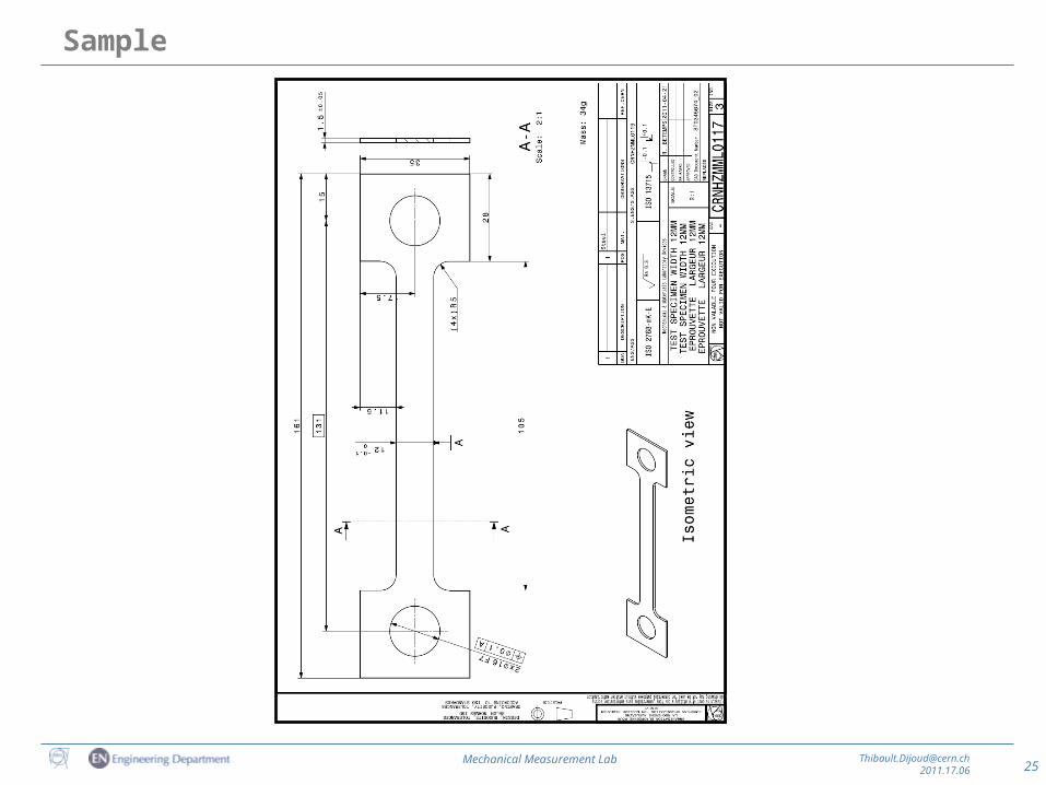
Mechanical Measurement Lab, 17.06.2011
T.Dijoud
Characterisation of the Strain Gauge Factor at Cryogenic Temperature
2Mechanical Measurement Lab [email protected]
2011.17.06
• Introduction
• Goal of the study
• Method
• Results
• Conclusion
Summary
3Mechanical Measurement Lab [email protected]
2011.17.06
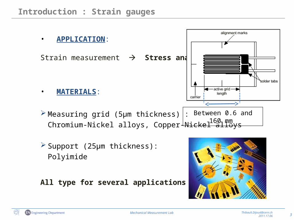
• APPLICATION:
Strain measurement Stress analysis
• MATERIALS:
Measuring grid (5μm thickness) : Chromium-Nickel alloys, Copper-Nickel alloys
Support (25μm thickness):Polyimide
All type for several applications
Introduction : Strain gauges
Between 0.6 and 160 mm Between 0.6 and 160 mm
4Mechanical Measurement Lab [email protected]
2011.17.06
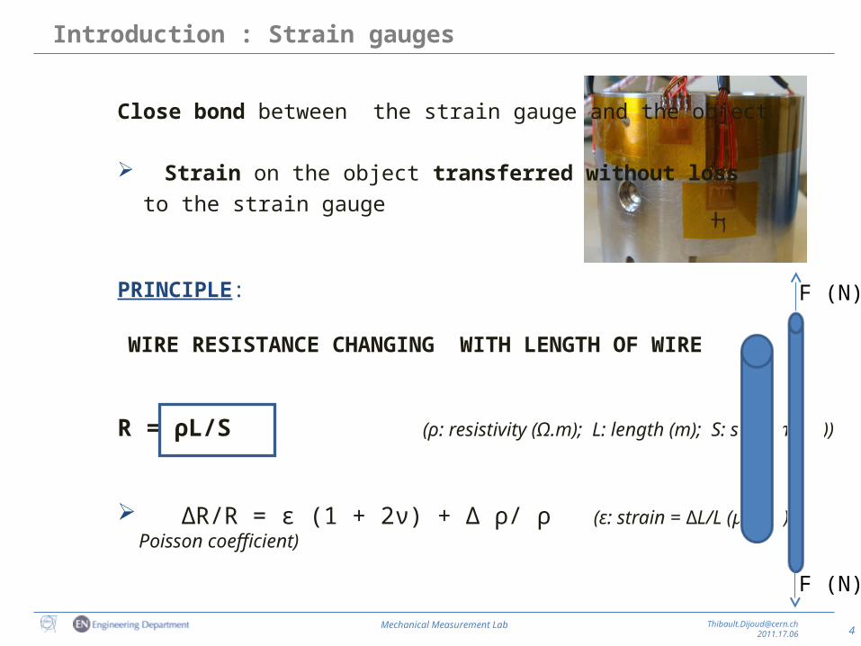
Close bond between the strain gauge and the object
Strain on the object transferred without loss to the strain gauge
PRINCIPLE:
WIRE RESISTANCE CHANGING WITH LENGTH OF WIRE
R = ρL/S (ρ: resistivity (Ω.m); L: length (m); S: section (m2))
∆R/R = ε (1 + 2ν) + ∆ ρ/ ρ (ε: strain = ∆L/L (μm/m); ν: Poisson coefficient)
Introduction : Strain gauges
F (N)
F (N)
5Mechanical Measurement Lab [email protected]
2011.17.06
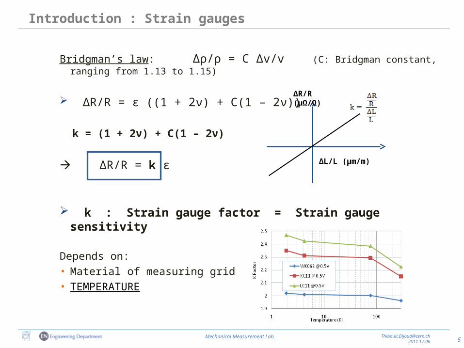
Bridgman’s law: ∆ρ/ρ = C ∆v/v (C: Bridgman constant, ranging from 1.13 to 1.15)
∆R/R = ε ((1 + 2ν) + C(1 – 2ν)) k = (1 + 2ν) + C(1 – 2ν)
∆R/R = k ε
k : Strain gauge factor = Strain gauge sensitivity
Depends on: • Material of measuring grid• TEMPERATURE
Introduction : Strain gauges
∆L/L (μm/m)
∆R/R (μΩ/Ω)
6Mechanical Measurement Lab [email protected]
2011.17.06
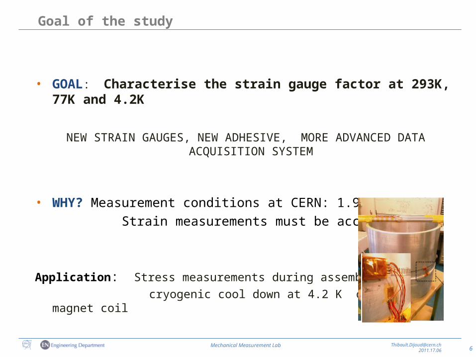
Goal of the study
• GOAL: Characterise the strain gauge factor at 293K, 77K and 4.2K
NEW STRAIN GAUGES, NEW ADHESIVE, MORE ADVANCED DATA ACQUISITION SYSTEM
• WHY? Measurement conditions at CERN: 1.9 K to 500 K Strain measurements must be accurate
Application: Stress measurements during assembly and cryogenic cool down at 4.2 K of short magnet coil
7Mechanical Measurement Lab [email protected]
2011.17.06
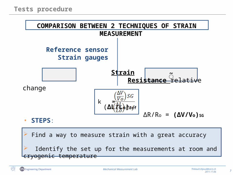
COMPARISON BETWEEN 2 TECHNIQUES OF STRAIN MEASUREMENT
Reference sensor Strain gauges
Strain Resistance relative change
(∆L/Lo)Ref ∆R/Ro = (∆V/Vo)SG
Tests procedure
k =
�̃
• STEPS:
Find a way to measure strain with a great accuracy
Identify the set up for the measurements at room and cryogenic temperature
8Mechanical Measurement Lab [email protected]
2011.17.06
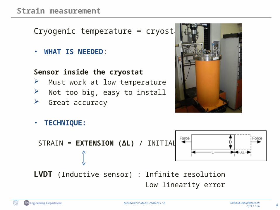
Strain measurement
Cryogenic temperature = cryostat
• WHAT IS NEEDED:
Sensor inside the cryostat Must work at low temperature Not too big, easy to install Great accuracy
• TECHNIQUE:
STRAIN = EXTENSION (∆L) / INITIAL LENGTH (L)
LVDT (Inductive sensor) : Infinite resolution Low linearity error
9Mechanical Measurement Lab [email protected]
2011.17.06
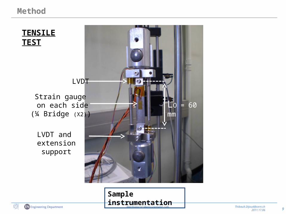
Method
LVDT and extension support
Strain gauge on each side
(¼ Bridge (X2))
LVDT
LO = 60 mm
Sample instrumentation
TENSILE TEST
10Mechanical Measurement Lab [email protected]
2011.17.06
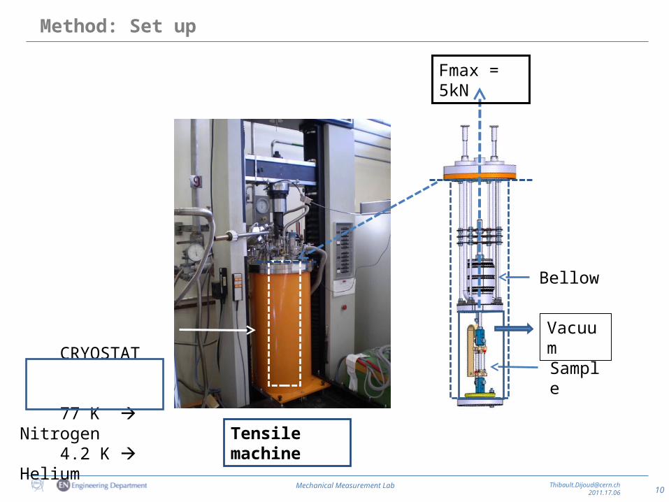
Method: Set up
CRYOSTAT
77 K Nitrogen 4.2 K Helium
Sample
Fmax = 5kN
Vacuum
Tensile machine
Bellow
11Mechanical Measurement Lab [email protected]
2011.17.06
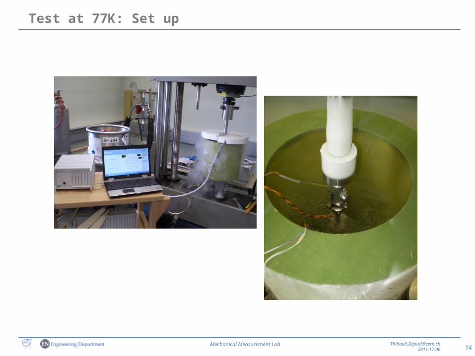
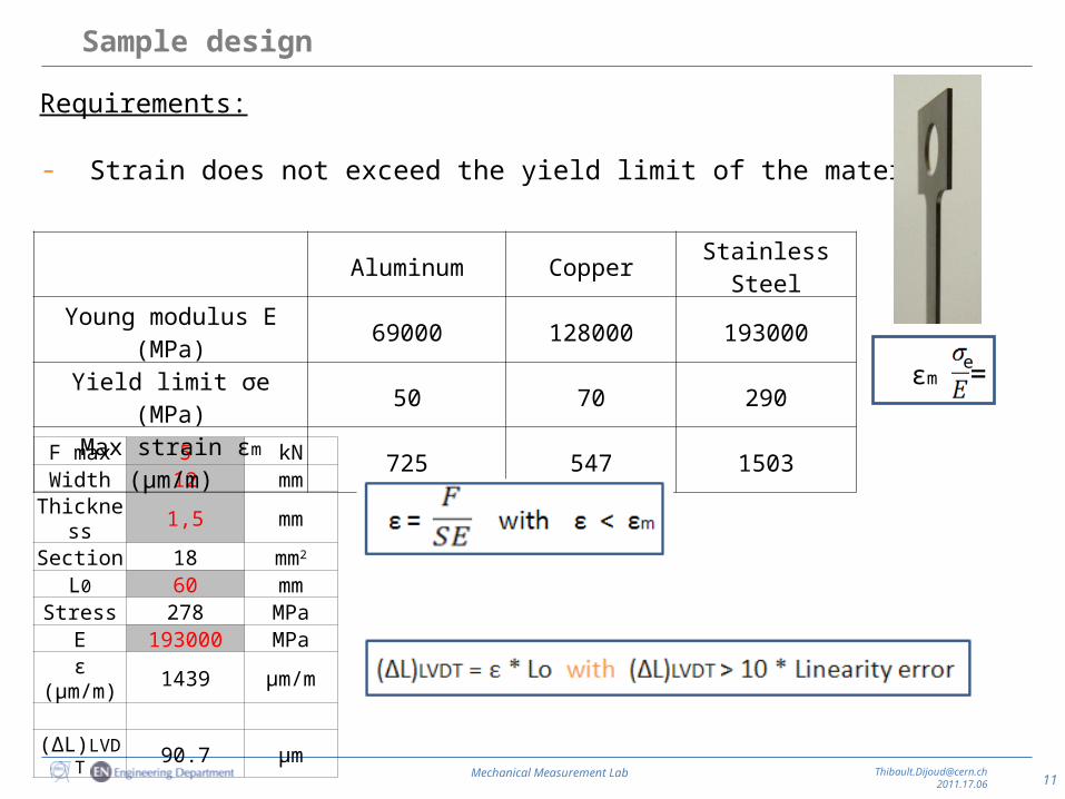
Sample design
F max 5 kNWidth 12 mm
Thickness 1,5 mmSection 18 mm2
L0 60 mmStress 278 MPa
E 193000 MPaε (μm/m) 1439 µm/m
(∆L)LVDT 90.7 µm
Aluminum Copper Stainless Steel
Young modulus E (MPa) 69000 128000 193000
Yield limit σe (MPa) 50 70 290
Max strain εm (μm/m) 725 547 1503 εm = e
Requirements:
- Strain does not exceed the yield limit of the material
13Mechanical Measurement Lab [email protected]
2011.17.06
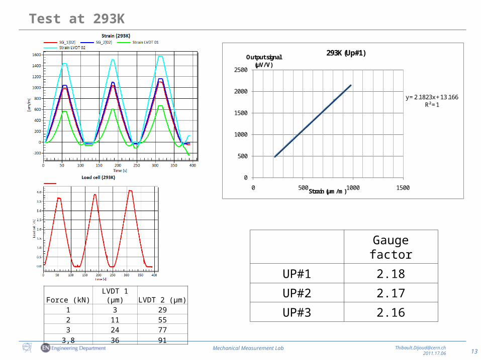
Test at 293K
y = 2.1823x + 13.166R² = 1
0
500
1000
1500
2000
2500
0 500 1000 1500
Output signal (μV/V)
Strain (μm/m)
293K (Up#1)
Gauge factor
UP#1 2.18
UP#2 2.17
UP#3 2.16Force (kN) LVDT 1 (μm) LVDT 2 (μm)
1 3 292 11 553 24 77
3,8 36 91
15Mechanical Measurement Lab [email protected]
2011.17.06
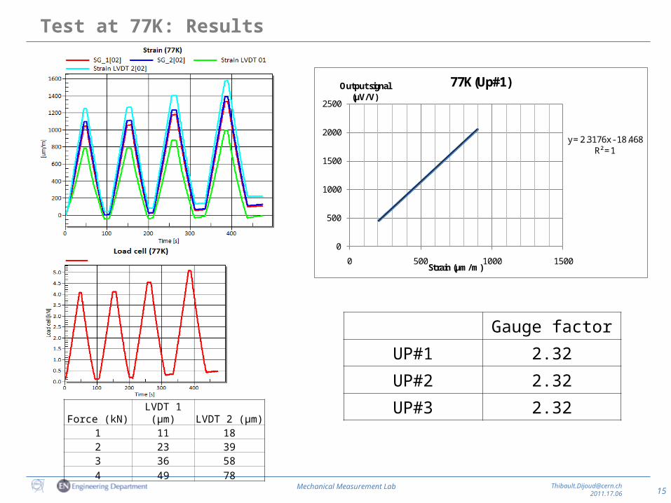
Test at 77K: Results
Gauge factor
UP#1 2.32
UP#2 2.32
UP#3 2.32
y = 2.3176x - 18.468R² = 1
0
500
1000
1500
2000
2500
0 500 1000 1500
Output signal (μV/V)
Strain (μm/m)
77K (Up#1)
Force (kN) LVDT 1 (μm) LVDT 2 (μm)1 11 182 23 393 36 584 49 78
16Mechanical Measurement Lab [email protected]
2011.17.06
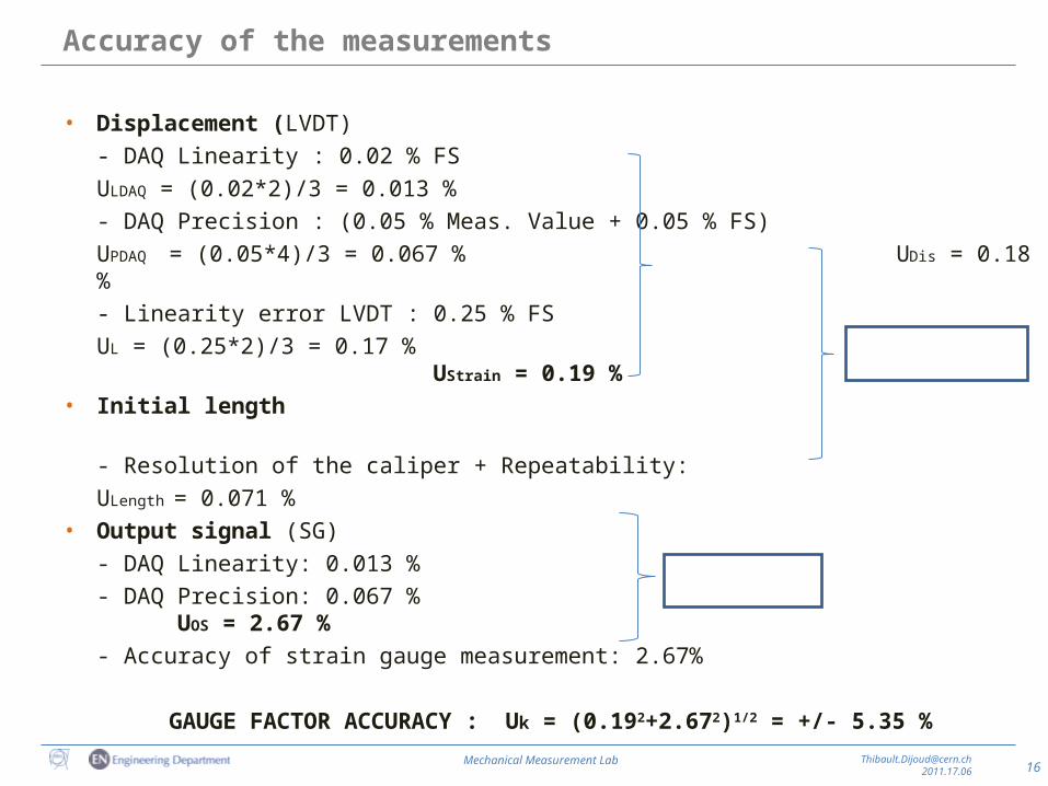
Accuracy of the measurements
• Displacement (LVDT)- DAQ Linearity : 0.02 % FS
ULDAQ = (0.02*2)/3 = 0.013 %- DAQ Precision : (0.05 % Meas. Value + 0.05 % FS)
UPDAQ = (0.05*4)/3 = 0.067 % UDis = 0.18 %- Linearity error LVDT : 0.25 % FS
UL = (0.25*2)/3 = 0.17 % UStrain = 0.19 %
• Initial length - Resolution of the caliper + Repeatability:
ULength = 0.071 %• Output signal (SG)
- DAQ Linearity: 0.013 %- DAQ Precision: 0.067 % UOS = 2.67 %- Accuracy of strain gauge measurement: 2.67%
GAUGE FACTOR ACCURACY : Uk = (0.192+2.672)1/2 = +/- 5.35 %
17Mechanical Measurement Lab [email protected]
2011.17.06
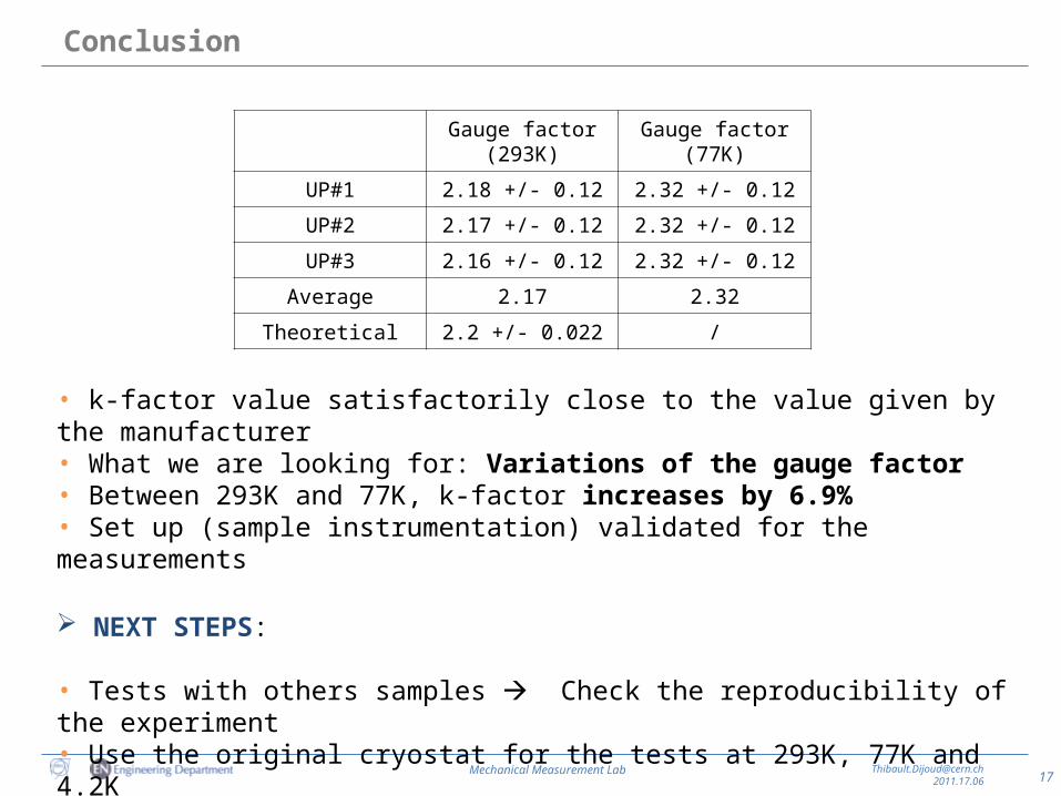
Conclusion
Gauge factor (293K) Gauge factor (77K)
UP#1 2.18 +/- 0.12 2.32 +/- 0.12
UP#2 2.17 +/- 0.12 2.32 +/- 0.12
UP#3 2.16 +/- 0.12 2.32 +/- 0.12
Average 2.17 2.32
Theoretical 2.2 +/- 0.022 /
• k-factor value satisfactorily close to the value given by the manufacturer • What we are looking for: Variations of the gauge factor • Between 293K and 77K, k-factor increases by 6.9%• Set up (sample instrumentation) validated for the measurements
NEXT STEPS:
• Tests with others samples Check the reproducibility of the experiment• Use the original cryostat for the tests at 293K, 77K and 4.2K
18Mechanical Measurement Lab [email protected]
2011.17.06
Thanks to
Thanks to Ofelia Capatina and Ramon Folch for this period at CERN
Thanks to Michael, Eugenie, Andrey, Raul, Alex, Robin,
Jean-Michel, Kurt and Rosmarie
Thank you for your attention!
20Mechanical Measurement Lab [email protected]
2011.17.06
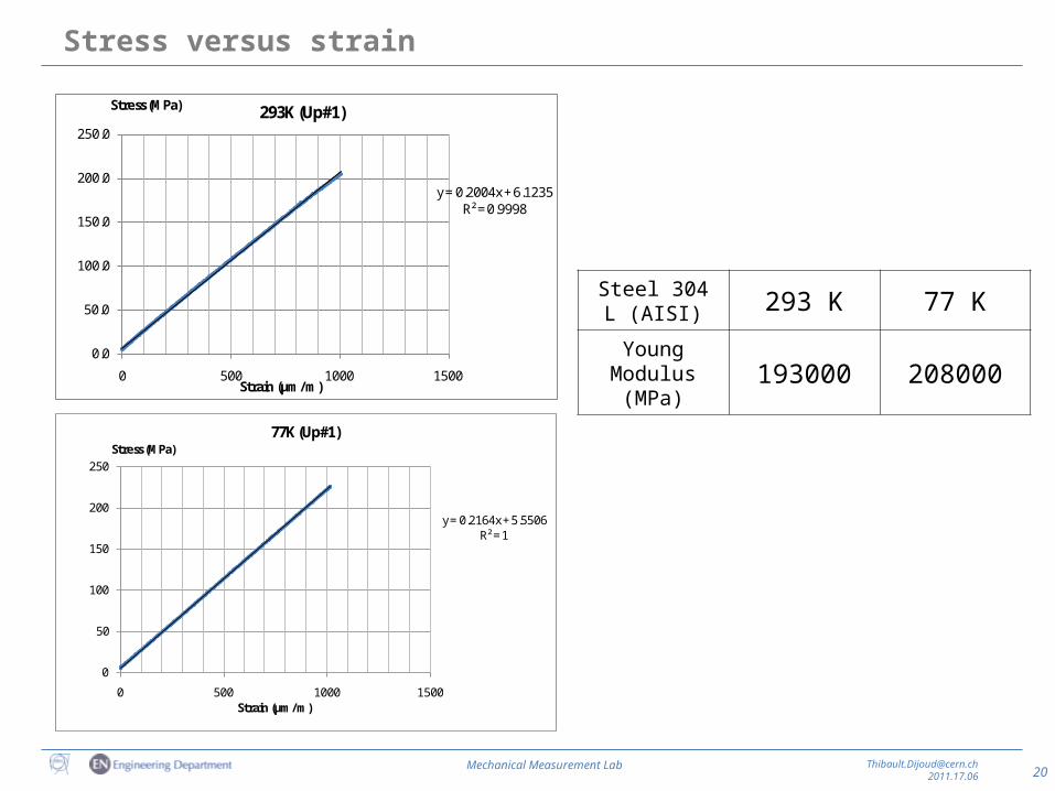
Stress versus strain
Steel 304 L (AISI) 293 K 77 K
Young Modulus(MPa) 193000 208000
y = 0.2004x + 6.1235R² = 0.9998
0.0
50.0
100.0
150.0
200.0
250.0
0 500 1000 1500
Stress (MPa)
Strain (μm/m)
293K (Up#1)
y = 0.2164x + 5.5506R² = 1
0
50
100
150
200
250
0 500 1000 1500
Stress (MPa)
Strain (μm/m)
77K (Up#1)
21Mechanical Measurement Lab [email protected]
2011.17.06
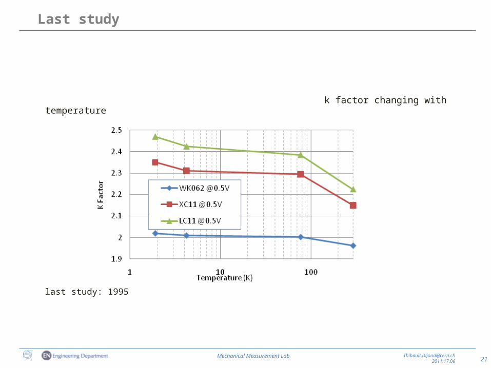
Last study
k factor changing with temperature
last study: 1995
22Mechanical Measurement Lab [email protected]
2011.17.06
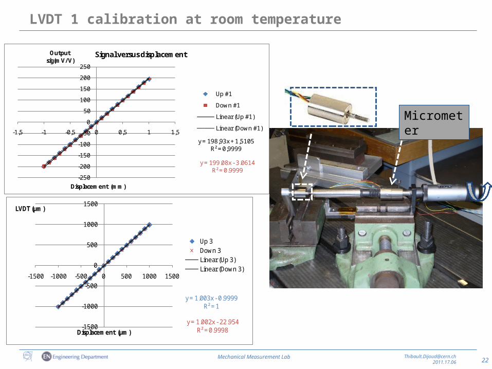
y = 198,93x + 1,5105R² = 0,9999
y = 199.08x - 3.0614R² = 0.9999
-250
-200
-150
-100
-50
0
50
100
150
200
250
-1,5 -1 -0,5 0 0,5 1 1,5
Output sig(mV/V)
Displacement (mm)
Signal versus displacement
Up #1
Down #1
Linear (Up #1)
Linear (Down #1)
LVDT 1 calibration at room temperature
y = 1.003x - 0.9999R² = 1
y = 1.002x - 22.954R² = 0.9998-1500
-1000
-500
0
500
1000
1500
-1500 -1000 -500 0 500 1000 1500
LVDT (μm)
Displacement (μm)
Up 3Down 3Linear (Up 3)Linear (Down 3)
Micrometer
23Mechanical Measurement Lab [email protected]
2011.17.06
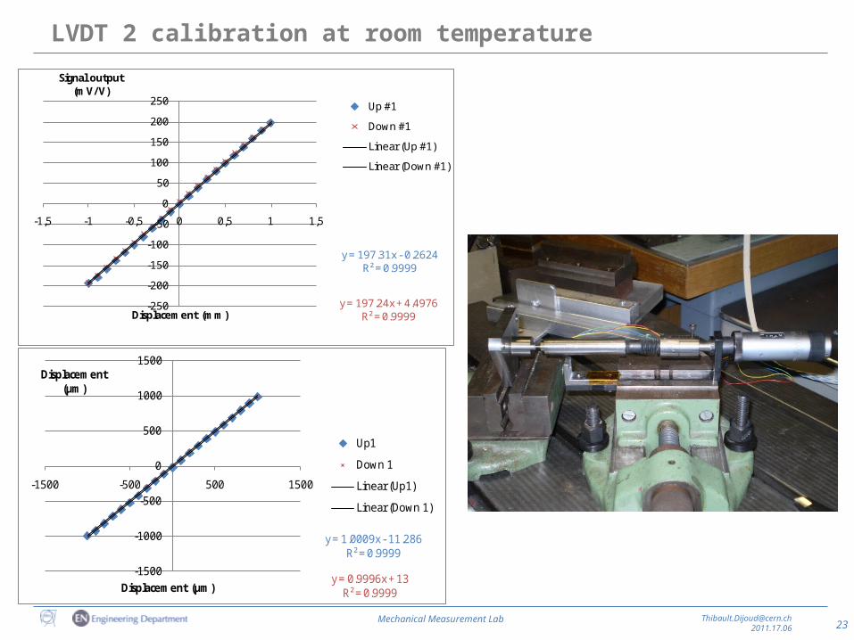
LVDT 2 calibration at room temperature
y = 197.31x - 0.2624R² = 0.9999
y = 197.24x + 4.4976R² = 0.9999
-250
-200
-150
-100
-50
0
50
100
150
200
250
-1,5 -1 -0,5 0 0,5 1 1,5
Signal output (mV/V)
Displacement (mm)
Up #1
Down #1
Linear (Up #1)
Linear (Down #1)
y = 1.0009x - 11.286R² = 0.9999
y = 0.9996x + 13R² = 0.9999
-1500
-1000
-500
0
500
1000
1500
-1500 -500 500 1500
Displacement (μm)
Displacement (µm)
Up1
Down 1
Linear (Up1)
Linear (Down 1)
24Mechanical Measurement Lab [email protected]
2011.17.06
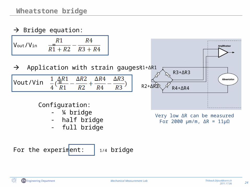
Wheatstone bridge
Bridge equation:
Vout/Vin =
Application with strain gauges:
Vout/Vin =
Configuration:- ¼ bridge- half bridge- full bridge
For the experiment: 1/4 bridge
R1+∆R1
R2+∆R2
Very low ∆R can be measuredFor 2000 µm/m, ∆R = 11µΩ
R3+∆R3
R4+∆R4