Mechanical Elements Space frames - City University Londonra600/ME1105/Lectures/ME1110-… · ·...
29
Ahmed Kovacevic, City University London Design web 1 Mechanical Elements Space frames Prof Ahmed Kovacevic School of Engineering and Mathematical Sciences Room CG25, Phone: 8780, E-Mail: [email protected] www.staff.city.ac.uk /~ra600/intro.htm Engineering Drawing and Design - Lecture 17 ME 1110 – Engineering Practice 1
-
Upload
nguyendang -
Category
Documents
-
view
213 -
download
0
Transcript of Mechanical Elements Space frames - City University Londonra600/ME1105/Lectures/ME1110-… · ·...

Ahmed Kovacevic, City University London
Design web
1
Mechanical Elements Space frames
Prof Ahmed Kovacevic
School of Engineering and Mathematical SciencesRoom CG25, Phone: 8780, E-Mail: [email protected]
www.staff.city.ac.uk/~ra600/intro.htm
Engineering Drawing and Design - Lecture 17
ME 1110 – Engineering Practice 1
Ahmed Kovacevic, City University London
Design web
2
Introduction Mechanical engineering deals mostly with machines and
mechanisms. Civil engineering deals with structures. Some structures are very interesting for mechanical engineers:
» Airplane fuselage» Machine frames» Car chassis …
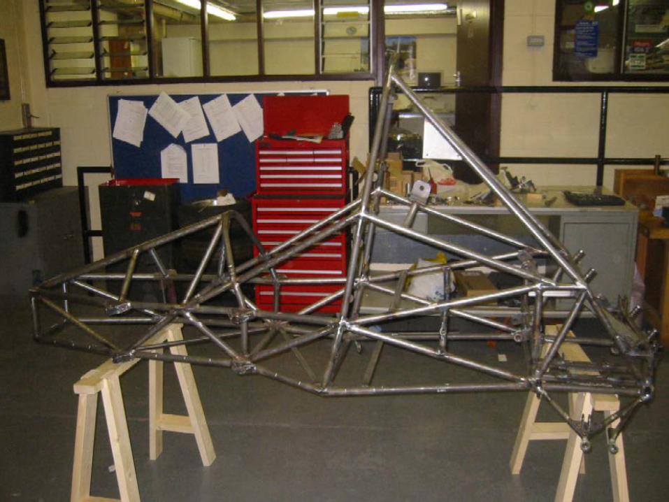
Formula student project - design of a racing car

Ahmed Kovacevic, City University London
Design web
3
Facts about car structure
Chassis» The most common type of structure used on the early cars 1900’s» Still used on trucks & lorries, Black-Cab taxis» It provides structural platform onto which is mounted a body. Example: in the UK the
Land Rover ‘Defender’ and ‘Discovery’ Monocoque
» It is currently the standard structure for most cars made around the world in high volume production (100,000+per annum). First introduced by Budd in 1930’s.
» Constructed from pressed sheet steel, it combines the function of both chassis and body in a three dimensional structure.
» In its purest sense, the term monocoque is applied to a structure which relies entirely on its outer skin for strength.
» Most cars (except Jaguar E type) have additional stiffening elements –‘Semi-monocoque’
» Lighter then chassis and easier to manufacture

Ahmed Kovacevic, City University London
Design web
4
Facts about car structure - 2
Space frame» Originally developed for performance cars such
as Maserati in the early 1950’s. as ‘cage’ of welded tubes onto which a non-structural body shell is attached.
» The spaceframe, unlike the monocoque, relies on an internal tubular cage or frame to provide all the load bearing qualities of the vehicle.
» Spaceframes are more labour intensive than the welded steel monocoque due a greater number of parts required in constructing the body.
» The arrival of the Multipla and Audi A2 challenges the generally accepted view of a technology associated with expensive, low volume cars. For the first time a structure very close to that of a true spaceframe is going to be used to build medium volume production runs of around 50,000 units a year.
Composite» Made out of two or more different materials that can be conveniently and easily
formed. Lightweight, high strength, easy to manufacture,

Ahmed Kovacevic, City University London
Design web
5
Frames -Definition• Frames are structures that always contain
at least one member acted on by forces at three or more points (three or more force members). Frames are constructed and supported so as to prevent any motion.
• Frame-like structures that are not fully constrained are called machines or mechanisms.
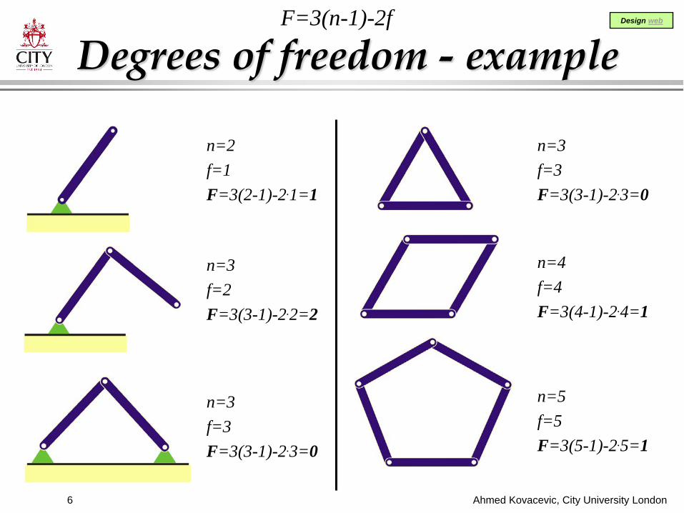
• Degrees of freedom: F=3(n-1)-2fn – total number of linksf – total number of joints
• Frames have 0 degrees of freedom, machines have more
Ahmed Kovacevic, City University London
Design web
6
Degrees of freedom - example
n=2f=1F=3(2-1)-2.1=1
n=3f=2F=3(3-1)-2.2=2
n=3f=3F=3(3-1)-2.3=0
n=3f=3F=3(3-1)-2.3=0
n=4f=4F=3(4-1)-2.4=1
n=5f=5F=3(5-1)-2.5=1
F=3(n-1)-2f

Ahmed Kovacevic, City University London
Design web
7
Trusses -Definition
• Trusses are special cases offrames. These are structurescomposed entirely of members that are loaded with forces in two points (two force members).
• These consist generally oftriangular sub-element and areconstructed and supported so as to prevent any motion.

Ahmed Kovacevic, City University London
Design web
8
Planar Trusses lie in a single plane and all applied loads must lie in the same plane.
Planar Truss
Ahmed Kovacevic, City University London
Design web
9
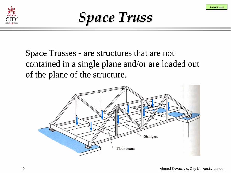
Space Truss
Space Trusses - are structures that are not contained in a single plane and/or are loaded out of the plane of the structure.

Ahmed Kovacevic, City University London
Design web
10
Truss
There are four main assumptions made in the analysis of truss The truss is made up of single bars, which are either in
compression, tension or no-load. Truss members are connected together at their ends only. Truss are connected together by
frictionless pins. The truss structure is loaded only
at the joints. The weights of the members may
be neglected.

Ahmed Kovacevic, City University London
Design web
11
2D Truss
The basic building block of a truss is a triangle. Large truss are constructed by attaching several triangles together A new triangle can be added to a truss by adding two members and a joint.
A truss constructed in this fashion is known as a simple truss.

Ahmed Kovacevic, City University London
Design web
12
Simple 2D TrussTo determine if a 2D (planar) truss is solvable:
determinacy d=m+r-2.jm - number of members,j - number of joints, r - represents the external support reactionsr=3 for 2D truss
d < 0 the truss is unstable and will collapse under load (unstable),
d = 0 the truss is rigid and solvable (determinate),
d > 0 the truss has more unknowns than equations and it is indeterminate structure.

Ahmed Kovacevic, City University London
Design web
13
Simple Truss- IdentifyDetermine type of a simple truss
m=12 j=8 unstable12 < 2.8-3=13
m=15 j=8 indeterminate15 > 2.8-3=13
m=13 j=8 determinate13 < 2.8-3=13
m=13 j=8 determinate13 < 2.8-3=13
m=2.j-3

Ahmed Kovacevic, City University London
Design web
14
3D Truss
The difference between 2-D and 3-D truss is that there are three more equations because of the 3D nature of the problem.
A 3D truss if constructed only from triangles attachedtogether is also a simple truss.

Ahmed Kovacevic, City University London
Design web
15
Simple 3D Truss
To determine if a 3D (space) truss is solvable:determinacy d=m+r-3.j
m - number of members,j - number of joints, r - represents the external support reactions
d < 0 the truss is unstable and will collapse under load (unstable),
d = 0 the truss is rigid and solvable (determinate),
d > 0 the truss has more unknowns than equations and it is indeterminate structure.

Ahmed Kovacevic, City University London
Design web
16
How to Calculate Truss?
• The method of joints employs the summation of forces at a joint to calculate forces in members.It does not use the moment equilibrium equation to solve the problem.
Method is convenient if forces in all members are to be calculated. It will be explained in more details later.
x
y
z
0
0
0
F
F
F
=
=
=
∑∑∑
• Forces in a Truss members can be calculated by:
• Methods of Joints• Methods of Sections

Ahmed Kovacevic, City University London
Design web
17
How to Calculate Truss?
• The method of sectionsConvenient method if only the force in one member is required.
In this method a cutting line is used to breakup the truss in two parts.
Moment equation in the most convenient point is then used to calculate a force acting to the member of interest.
Example, force acting in member CE:
B 1 10 : 0CE CEABM P AB F CB F PCB
= ⋅ + ⋅ = ⇒ = −∑

Ahmed Kovacevic, City University London
Design web
18
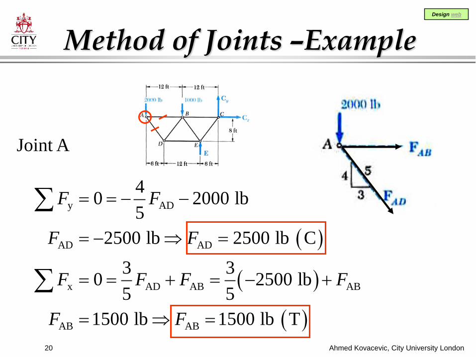
Method of Joints –Example
Using the method of joints, determine the force in each member of the planar truss.

Ahmed Kovacevic, City University London
Design web
19
Method of Joints –Example
Calculate restraint reactions
Draw the free body diagram of the truss and solve for the equations:
( ) ( ) ( )
x x
y y y
C
y
0 : 0
0 : 2000-1000 0 3000 lb
0 : 2000 24 ft 1000 12 ft 6 ft 10000 lbC 3000 10000 7000 lb
F C
F E C E C
M E E
= =
= + + = ⇒ + =
= + − ⇒ =
= − = −
∑∑∑
Ahmed Kovacevic, City University London
Design web
20
Method of Joints –Example
Joint A
( )
( )
( )
y AD
AD AD
x AD AB AB
AB AB
40 2000 lb5
2500 lb 2500 lb C3 30 2500 lb5 5
1500 lb 1500 lb T
F F
F F
F F F F
F F
= = − −
= − ⇒ =
= = + = − +
= ⇒ =
∑
∑

Ahmed Kovacevic, City University London
Design web
21
Method of Joints –Example
Joint D
( )
( )
( ) ( )
( )
y AD DB DB
DB DB
x AD DB DE DE
DE DE
4 4 4 40 25005 5 5 5
2500 lb 2500 lb T3 3 3 30 2500 25005 5 5 5
3000 lb 3000 lb C
F F F F
F F
F F F F F
F F
= = + = − +
= ⇒ =
−= = − + + = − + +
= − ⇒ =
∑
∑
Ahmed Kovacevic, City University London
Design web
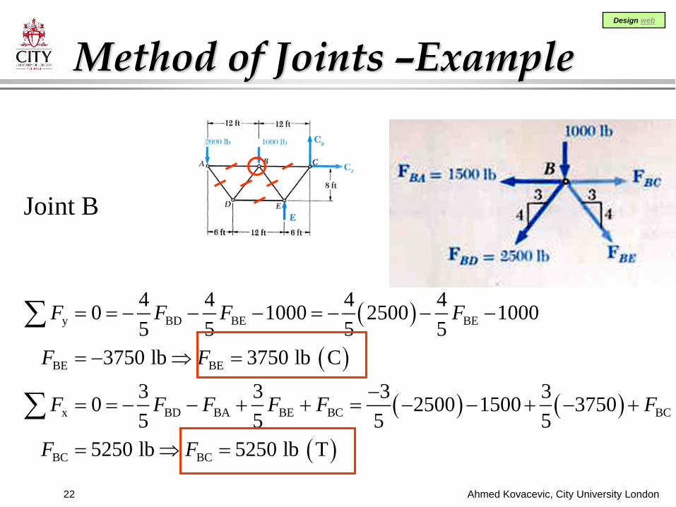
22
Method of Joints –Example
Joint B
( )
( )
( ) ( )
( )
y BD BE BE
BE BE
x BD BA BE BC BC
BC BC
4 4 4 40 1000 2500 10005 5 5 5
3750 lb 3750 lb C3 3 3 30 2500 1500 37505 5 5 5
5250 lb 5250 lb T
F F F F
F F
F F F F F F
F F
= = − − − = − − −
= − ⇒ =
−= = − − + + = − − + − +
= ⇒ =
∑
∑

Ahmed Kovacevic, City University London
Design web
23
Method of Joints –Example
Joint E
( )
( )
( ) ( )
( )
y EB EC DE
EC EC
x EB ED EC EC
EC EC
4 4 4 40 3750 100005 5 5 5
8750 lb 8750 lb C3 3 3 30 3750 30005 5 5 5
8750 lb 8750 lb C
F F F E F
F F
F F F F F
F F
= = − + + = − − + +
= − ⇒ =
= = − − + = − − − − +
= − ⇒ =
∑
∑
(maximum load)
(check the solution)

Ahmed Kovacevic, City University London
Design web
24
Method of Joints –Example
Joint C
(check the solution)
( )
( )
y CE
x CE CB x
4 40 8750 7000 05 53 30 8750 5250 05 5
yF F C
F F F C
= = − − = − − − =
= = − − + = − − − =
∑
∑

Ahmed Kovacevic, City University London
Design web
25
COMPETITION: Load/weight ratioWinner 20 extra marks

Ahmed Kovacevic, City University London
Design web
26

Ahmed Kovacevic, City University London
Design web
27

Ahmed Kovacevic, City University London
Design web
28

Ahmed Kovacevic, City University London
Design web
29
Last Year Winner