Mec · PDF fileThe Model II-D Firing Head requires a minimum of 1,500 psi hydrostatic pressure...
30
The Extended Mechanical Firing Head (MFH) is a special application tool. It should be used only when well conditions preclude the use of an alternate firing device. Whenever it is used on a job, the MFH must be used as prescribed by appropriate tool manuals. Operation The operation of the MFH depends on the amount of force delivered to the firing pin by the detonating bar. The firing pin must be hit with enough force to shear the spiral pin, which holds the firing pin in place, and to detonate the initiator. The firing pin is driven into a percussion detonator, which fires the guns. The Detonation Interruption Device (DID) and a min- imum of 10 ft of safety space must always be used with the Mechanical Firing Head. Mechanical Firing Head Mechanical Firing Head www.fumakgroup.com +234 703 066 2562 [email protected]
-
Upload
phungkhanh -
Category
Documents
-
view
216 -
download
2
Transcript of Mec · PDF fileThe Model II-D Firing Head requires a minimum of 1,500 psi hydrostatic pressure...

The Extended Mechanical Firing Head (MFH) is a special application tool. It should be used only when well conditions preclude the use of an alternate firing device. Whenever it is used on a job, the MFH must be used as prescribed by appropriate tool manuals.
Operation
The operation of the MFH depends on the amount of force delivered to the firing pin by the detonating bar. The firing pin must be hit with enough force to shear the spiral pin, which holds the firing pin in place, and to detonate the initiator. The firing pin is driven into a percussion detonator, which fires the guns.
The Detonation Interruption Device (DID) and a min-imum of 10 ft of safety space must always be used with the Mechanical Firing Head.
Mechanical Firing Head
Mechanical Firing Head
www.fumakgroup.com +234 703 066 2562 [email protected]
Tunde
Stamp

Mechanical Firing Head
Mechanical Firing Head
Mechanical Firing Head
Mechanical Firing Head Sub-Assembly
Thread Size and Type in. (mm)
1.90 (48.26) NU 10 Rd pin x 2 3/8 (60.33) 6P
Acme box
2 3/8 (60.33) EUE 8 Rd pin x 2 7/8 (73.03) 6P
Acme box
1 7/16 (36.51) 8 UN 2 B Box x 1.90 (48.26)
NU 10 RD Pin
Assembly Number 100005228 100005223 100155741Extreme Environment
Kit 100156259 100156259 N/A
Redress Kit N/A N/A 100014388
Maximum OD 2.75 (69.85) 3.375 (85.73) 2.0 (50.8)
in. (mm)Minimum ID (No-Go)
1.56 (39.62) 1.56 (39.62) 1.53 (38.86)in. (mm)
Maximum Operating 20,000 (1380) 20,000 (1380) 20,000 (1380)
PressureMinimum Operating
None None None Pressure psi (bars)Flow Area N/A N/A N/A
Temperature RatingDetermined by Determined by Determined by
explosives explosives explosivesTensile Strength
140,000 (63 400) 238,000 (107 900) 60,000 (27 200)(FH body)lb (kg)
Burst Pressure Determined by Determined by25,000 (1725)
psi (bars) handling sub handling sub
Collapse Pressure Determined by Determined by 20,000 (1380)
psi (bars) handling sub handling subOverall Length
4.58 (1.40) 4.58 (1.40) 1.59 (0.48)(w/o tubing sub) ft (m)
www.fumakgroup.com +234 703 066 2562 [email protected]
Tunde
Stamp

Detonation Interruption Device
The Detonation Interruption Device (DID) provides additional safety for the VannGun™ System. This safety device contains an eutectic metal that protects the initiator from the firing pin at surface conditions. The eutectic metal has a very low melting point, but while it is in a solid state, the metal in the DID will stop the explosive train from being transmitted to the perforating assembly after the firing head has been detonated.
Operation
A minimum bottomhole temperature (BHT) of 135 oF is required to run the DID. Unless the DID is ex-posed to high surface temperatures, the eutectic met-al will be solid when the assembly starts in the hole. When it is warmed to the BHT, the eutectic metal is liquified and allows the transfer of the explosive train from the firing head to the perforating assembly. If the guns are pulled out of the hole before they are fired, the eutectic metal will return to a solid state as it reaches the cooler temperatures near the surface. This device helps prevent accidental firing of the guns when they are started in the hole or pulled out.
Features and Benefits
• Is compatible with all firing heads
• Disables the perforating assembly at surface
• Can be used with redundant firing heads
Detonation Interruption Device
www.fumakgroup.com +234 703 066 2562 [email protected]
Tunde
Stamp

Model II-D Mechanical Firing Head
The Model II-D Mechanical Firing Head is a pres-sure-assisted mechanical firing head. The detonating car strikes the firing pin, releasing the firing piston. Hydrostatic pressure then forces the firing piston into the initiator.
Operation
The Model II-D Firing Head requires a minimum of 1,500 psi hydrostatic pressure in the tubing to actuate the firing head properly. Adding more pressure to the tubing after the detonating bar has struck the fir-ing pin will not actuate the firing head.
Features and Benefits
• Cannot be detonated accidentally at surface
• Is ideal for use in mud environments where spud-ding may be necessary
• Can be used in deviated wells
Model II-D Mechanical Firing Head
www.fumakgroup.com +234 703 066 2562 [email protected] +234 703 066 2562 [email protected]
www.fumakgroup.com +234 703 066 2562 [email protected]

Model III-D Mechanical Firing Head
The Model III-D Mechanical Firing Head is a pressure-assisted mechanical firing head. The detonating bar strikes the firing pin, releasing the firing piston. Hydrostatic pressure then forces the firing piston into the initiator. The Model III-D Firing Head requires a minimal amount of hydrostatic pressure to actuate the firing head.
Operation
The Model III-D Firing Head requires a minimum of 250 psi hydrostatic pressure in the tubing to actuate the firing head properly. This minimal actuating pressure is ideal for applications that require maxi-mum differential pressures. Adding more pressure to the tubing after the detonating bar has struck will not actuate the firing head.
Features and Benefits
• Cannot be detonated accidentally at surface
• Is ideal for use in mud environments where spud-ding may be necessary
• Can be used in deviated wells
• Requires minimal hydrostatic pressure to actuatethe firing head
Model III-D Mechanical Firing Head
www.fumakgroup.com +234 703 066 2562 [email protected]

Pressure-Actuated Firing Head
The 1 11/16-in. Pressure-Actuated Firing Head (PAF) can run with small OD tubing or coiled tubing to detonate small OD perforating guns. The PAF is detonated by pressure applied to the tubing string.
Operation
The 1 11/16-in. PAF consists of an upper housing with circulating ports, a firing piston that is shear-pinned in place across the circulating ports, and an initiator contained in a lower housing. Pressure ap-plied to the tubing string shears the shear set, which forces the firing piston into the initiator to detonate the explosive component attached to the PAF. The downward movement of the firing piston opens the circulating ports.
Features and Benefits
• Can be run on the top and bottom of the gun as-sembly
• Initiates a bridge-plug and setting tool
• Initiates tubing cutters
• Detonates tubing punch charges for squeeze orcirculating jobs
• Can be run to remain closed after detonation
• Can be modified to be run as a slickline retrievablefiring head and a Time-Delay Firing Head
Pressure-Actuated Firing Head
www.fumakgroup.com +234 703 066 2562 [email protected]

Model K Series Firing Head
The Model K Series Firing Head was developed for conditions that are unfavorable for dropping a deto-nating bar in a horizontal well. The Model K Firing Head is a pressure-sensitive tool designed to hydrau-lically detonate at a prescribed pressure. These firing heads use tubing pressure applied to a piston-type firing pin.
Operation
The Model K Series Firing Head is designed to pro-vide a reliable and cost-effective method for firing guns using hydrostatic pressure. Each firing head contains a firing piston that is shear-pinned in place above and initiator. The number of shear pins used varies for each well situation. When enough hydro-static pressure is applied to the piston, the shear pins shear, thereby allowing the firing pin on the lower end of the piston to be driven into the initiator. This action detonates the guns. These firing heads do not have a built-in delay.
Features and Benefits
• Allow the operator to determine the exact timeof firing the guns since the firing heads require a predetermined pressure before the guns can fire
• Work with full-opening or nonfull-opening down-hole tools
• Are ideal for balanced or overbalanced perforating
• Can be used for dual completions, drillstem test-ing, or production perforating
• Are well-suited for highly deviated well completions
• Can be run on the top or bottom of the perforatingassembly
• Can be easily redressed
Model K Series Firing Head
www.fumakgroup.com +234 703 066 2562 [email protected]

Model KV-II Series Firing Head
The KV-type firing head design combines a firing head with a vent assembly. The KV-II Firing Head makes the firing of the guns and the opening for the vent one operation rather than two. This tool allows the operator more accurate control of when the vent opens in relation to when the guns fire.
Operation
In many tubing-conveyed perforating (TCP) applications, it is either desirable or necessary to keep the tubing closed until the guns have been detonated. In the past, the tubing was kept closed by a firing head with some type of vent assembly. Coordination between the two tools was sometimes hard to achieve, and the vent often opened either too soon or too late. The KV-II Firing Head combines a firing head and a vent assembly. A piston is sheared to cause the guns to detonate and the ports to open and equalize (or vent) pressure. This venting feature allows operators to run the tubing in the hole dry if needed. In the standard KV-II Firing Head, the ports open the instant the firing head is actuated and the guns detonate. To delay the gun detonation, one or more devices may be added to the assembly.
Features and Benefits
• Useful in wells with open perforations where itis not possible to pressure up on the wellbore to actuate a firing head
• Useful in perforating and stimulation jobs wherethe tubing pressure exceeds the limitations of thecasing
• Useful because the firing head and vent operate atone pressure
• Ideal for deviated wells
• Piston-mechanically locked after firing
Model KV-II Series Firing Head
www.fumakgroup.com +234 703 066 2562 [email protected]

Time-Delay Firer
The Time-Delay Firer (TDF) allows under or overbalanced perforating through the use of a pressure-actuated firing head with a time-delay fuse. The delay fuse allows five to seven minutes for adjusting the actuating pressure in the tubing to achieve the desired pressure before firing the guns.
Operation
The TDF is run with a predetermined number of shear pins for specific well conditions. The tubing is pressured to the maximum actuating pressure slowly. The maximum pressure shears the pins in the shear set and forces the firing piston into the primer. The primer ignites the pyrotechnic delay fuse. The delay fuse burns for a predetermined time, between five and seven minutes, depending on the bottomhole temperature and then the perforating assembly.
Features and Benefits
• Allows independent perforating of selected zones
• Allows maximum use of under or overbalancedpressure
• Can be run in heavy mud systems
• Can be used with full-opening or nonfull-openingtools
• Reduces cost by allowing the running of multipleguns without gun spacers
• Is ideal for production completions, drillstem test-ing, and dual completions
• Is recommended for running on the top and bot-tom of gun assemblies
• Allows additional time-delay elements as neededfor increasing delay time
Time-Delay Firer
www.fumakgroup.com +234 703 066 2562 [email protected]

Extended Delay and Modular Delay Fuses
A delay fuse is an explosive device with a slow-burning fuse. Extended and modular delay fuses add time between the actuation of the firing head and the actual detonation of the guns. Each delay fuse lasts for seven minutes at 70 oF.
Operation
The extended delay assemblies contain one delay fuse and can be run with any other firing assembly. They are installed between the firing head and the guns. The modular delays are assembled with the firing head in one housing and become an integral part of the firing system. The modular delays are used primarily with the multi-action delay firing head, the 1 11/16 in. TDF firing head and the slickline-retrievable TDF firing head.
Features and Benefits
• Increase delay time when nitrogen is used toactuate the firing head to give additional time to bleed the nitrogen pressure down to the desired level
• Allow time for necessary actions to take placedownhole, such as increasing pressure to open apressure-actuated vent assembly
Extended Delay and Modular Delay Fuses
www.fumakgroup.com +234 703 066 2562 [email protected]

The Hydraulic-Actuator Firing (HAF) Head is a pressure-balanced tool that automatically fills the tubing string while it is running in the well. A stain-less steel ball is dropped from the surface or circu-lated into position. Pressure applied to the tubing string actuates the HAF.OperationA stainless steel ball is dropped from the surface or is circulated downhole into the hammer piston. Pressure applied to the tubing string shears the retaining pins and forces the hammer piston into the firing pin. The firing pin detonates the initiator, which sta1rts the detonation of the perforating as-sembly. Circulation is regained as soon as the firing pin has been sheared.
Features and Benefits
• Allows packerless completions
• Makes actuation easily observable
• Is useful in coiled tubing-conveyed completions,deviated wells, and through-tubing perforation
• Is reusable
• The smaller tool has a swivel incorporated intothe firing head assembly
• The smaller tool has a swivel incorporated intothe firing head assembly
Hydraulic-Actuator Firing Head
Hydraulic-Actuator Firing Head
www.fumakgroup.com +234 703 066 2562 [email protected]

The VannJet is developed to actuate the firing head in extremely high-temperature situations and for other applications where it is not desirable to run the firing head attached to the perforating assembly.
Operation
The VannJet firing head is run with the VannJet stinger. After the firing head is located on the top of the stringer, the slickline operator jars down to shear the brass retaining screws. When the retain-ing screws are sheared, the firing piston retaining dogs retract. The hydrostatic pressure then forces the firing piston into the initiator to detonate a shaped charge in the lower section of the VannJet. The explosives in the stinger are then detonated, and the explosive train continues to the VannGun™ assembly.
Features and Benefits
• Has an initiator that is exposed to hightemperature in the well for only a short time
• Incorporates a firing head that is not on the Vann-Gun™ assembly
• Offers a high degree of safety in high-temperatureoperations
• Is designed to be run on a slickline
• Is actuated mechanically by jarring with wireline
VannJet Model II
VannJet Model II
www.fumakgroup.com +234 703 066 2562 [email protected]

Slickline-Retrievable TDF Firing Head
The Slickline-Retrievable Time-Delay Firer (TDF) Firing Head is a combination of two assemblies: the slickline-retrievable firing head and a 1 11/16 in. TDF firing head. It is a pressure-actuated firing head with a built-in pyrotechnic time-delay assembly.
Operation
This firing head does not have to be run until after all pressure testing has been done and the heavy fluids have been displaced, which allows a reduced actuat-ing pressure for the firing head. This assembly al-lows the operator to run guns in the hole on the end of tubing without a firing head. This assembly can be run in on slickline and attached to the firing head after the tubing is in the hole. It can also be retrieved on slickline.
Features and Benefits
• Allows the guns to be run in the hole without anytype of firing mechanism installed
• Allows the retrieval and reinstallation of a mal-functioning firing head without pulling the guns
• Allows greatly reduced actuating pressures of thefiring head because the firing head does not haveto be in place when the guns are run
Slickline-Retrievable TDF Firing Head
www.fumakgroup.com +234 703 066 2562 [email protected]

Mechanical Tubing Release
The Mechanical Tubing Release (MTR) provides operators with the option of keeping or releasing the VannGun™ assembly from the tubing string. The MTR is usually run above the firing head and below the production ports below the packer. A standard shifting tool is used to operate the release mechanism in the MTR.
Operation
The MTR consists of three main components: the up-per housing, a lower finger release sub, and a latch. The latch retains the finger release sub in the hous-ing. To operate the MTR the user must:
1. Select the proper shifting tool and run it into thehole on slickline through the MTR.
2. Pick back up to engage the latch and lightly jarthe latch four or five times.
3. Go back down to verify the release of the Vann-Gun assembly.
Features and Benefits
• Frees the tubing for other tools and operationssuch as logging, production testing, and treating
• Provides a low-cost way to release the gunassembly
• Uses standard off-the-shelf shifting tools
• Does not have a time limit on dropping the gunassembly
• Leaves perforations uncovered to eliminate flowrestrictions
Mechanical Tubing Release
www.fumakgroup.com +234 703 066 2562 [email protected]

Multiaction-Delay Firing Head
The Multiaction-Delay Firing Head is a pressure-ac-tuated redundant firing system that can be run with any one of several other firing heads.
Operation
One side of the multiaction firing head will always be pressure-actuated. The other side of the firing head may be a bar drop-type head or another pressure-ac-tuated firing head. Either side of the firing head may be used as the primary or backup firing system.
Features and Benefits
• Allows the use of a redundant firing head withouthaving a firing head on the bottom of the gun string
• Allows multiple redundancy when a multiactionfiring head is placed on both the top and bottomof the gun string
• Allows operators to postpone the decision ofwhether to use the bar drop or pressure side ofthe firing head as the primary firing mechanism
• Allows use of additional delay elements
Multiaction-Delay Firing Head
www.fumakgroup.com +234 703 066 2562 [email protected] +234 703 066 2562 [email protected]
www.fumakgroup.com +234 703 066 2562 [email protected]

Differential Firing Head
The Differential Firing Head (DFH) was designed to allow underbalanced perforating with a differential pressure-actuated firing system. The DFH works by requiring the internal pressure to be greater than the external pressure. This condition can be created when pressure is applied to the ID or when the OD pressure is reduced. The pressure required to actu-ate the DFH may be lower than that used for other pressure-operated firing heads because it is operated by differential pressure.
Operation
The DFH is actuated after a predetermined differ-ential pressure is created in the firing head ID. This differential pressure can be created when surface pressure is applied to the tubing or by reducing the hydrostatic pressure to the annulus. When the predetermined differential pressure is reached, the shear pins holding the dog retainer piston will shear, allowing the dog retainer to move up. The upward movement releases the dogs holding the firing piston in place, and the internal pressure drives the firing piston into the initiator or primer.
Features and Benefits
• Allows underbalanced perforating in horizontalwells without a packer
• Is ideal for perforating with a sucker rod or sub-mersible pump in place
• Offers added safety because it is pressure-bal-anced when being run into the well
• Allows maximum underbalanced pressure inlow-pressure wells when mechanical firing is notdesirable
• Can be used when equipment or well conditionswill not permit the use of high pressures
• Allows the use of time-delay elements as needed
Differential Firing Head
www.fumakgroup.com +234 703 066 2562 [email protected]

Annulus-Pressure Firer-Control Line
The Annulus-Pressure Firer-Control Line (APF-C) was developed as a dual-firing system that allows the perforating guns to be detonated by annular pressure, a drop bar, or tubing pressure. The APF-C system consists of a pressure transfer reservoir, a sleeve through the packer mandrel, an adapter below the packer, and a control line to transmit pressure from the annulus above the packer to the APF-C firing head assembly on top of the guns. Any of the mechanical pressure-firing heads can be attached to the top of the APF-C firing head.
Operation
The APF-C system depends on the transfer of annular pressure through the packer down to the APF-C firing head. This pressure creates a differential pressure across the mandrel where the firing piston is housed. When the predetermined differential pressure is reached, the pins shear and the mandrel moves up and releases the firing piston, which is driven down by rathole pressure. The piston strikes the firing pin to set off the initiator. The operation of the drop bar or pressure-actuated firing head depends on which firing head system is used.
Features and Benefits
• Can be used with nonfull-opening test tools andpartially-filled tubing strings
• Can be used for drillstem testing or shoot-and-pull for gravel packs
• Can be used wherever a pressure-actuated tool isdesirable
• Is ideal for deviated wells
• Provides a system of two firing heads on top ofthe guns
• Can be run with a mechanical or pressure-actuat-ed firing head as a secondary firing mechanism
• Enhances safety because the annulus-operatedportion is pressure-balanced before the packer isset and the tester valve is opened
Annulus-Pressure Firer-Control Line
www.fumakgroup.com +234 703 066 2562 [email protected]

Annulus-Pressure Transfer Reservoir
The Annulus-Pressure Transfer Reservoir (APTR) is an integral component of the Annulus-Pressure Firer-Control line (APF-C). The APTR is the mechanism that transmits pressure from above the packer to a differential pressure or pressure-actuated firing head on top of the perforating assembly.
Operation
The APTR transmits annulus pressure into a microannulus created by the packer mandrel and the APTR mandrel. The pressure is ported to a control line sub on the lower end of the packer. A stainless steel control line connects the APTR to the pressure-responsive firing head on the perforating assembly.
Features and Benefits
• Features a full-opening ID
• Is compatible with mud environments
• Is adapted for RTTS and CHAMP® packers
• Is ideal for applications that require a partial fluidcolumn in the tubing string
• Eliminates the need for nitrogen
Annulus-Pressure Transfer Reservoir
www.fumakgroup.com +234 703 066 2562 [email protected]

APF-C Vent
The Annulus-Pressure Firer-Control Vent (APF-C Vent) is a device that isolates the tubing from annulus fluid or pressure. The vent is actuated by rathole pressure after the perforating assembly has been detonated. It then provides a flowpath for the formation fluid into the tubing string.
Operation
The APF-C Vent is run directly on top of the APF-C Fir-ing Head. When the perforating assembly is detonated, the rathole pressure shifts an actuating piston into a power piston. The shift opens the flow ports to the tubing.
Features and Benefits
• Is ideal for highly deviated or horizontal wells
• Requires minimal pressure to operate
• Eliminates nitrogen displacement or swabbing thetubing string to achieve desired underbalance
APF-C Vent
www.fumakgroup.com +234 703 066 2562 [email protected]

Pressure-Actuated Tubing Release
The Pressure-Actuated Tubing Release (PATR) is used to separate the guns from the tool string when mechanical or slicklike devices are not desirable. When separated, the guns drop off of the production tubing. Once the guns drop away, other tools and operations have no restrictions through the end of the tubing. In fact, the housing attached to the string has a greater ID than the tubing.
Operation
The PATR consists of four main components: an upper housing, lower finger release sub, inner sleeve, and retaining latch. The PATR is pressure-balanced until the standing valve is dropped into the inner sleeve. Tubing pressure is applied to shear the retaining pins in the latch. Once the latch has been shifted, the finger release sub with the sleeve releases from the housing and drops the perforating assembly into the rathole.
Features and Benefits
• Leaves the tubing string fully open
• Is ideal for use in remote areas where wireline isexpensive or unfavorable
• Is ideal for situations where wireline can cause asafety hazard
• Provides access to the wellbore for productionlogging tools
• Is especially suited for releasing guns prior tostimulation treatments
Pressure-Actuated Tubing Release
www.fumakgroup.com +234 703 066 2562 [email protected]
www.fumakgroup.com +234 703 066 2562 [email protected]

Pressure-Actuated Tubing Release
Pressure-Actuated Tubing Release
These ratings are guidelines only. For more information, consult your local JRC representative.
Pressure-Actuated Tubing Release
Thread Size and Type 2 3/8 (60.33) EUE 2 7/8 (73.03) EUE 3 1/2 (88.9) EUE
in. (mm) 8 Rd box x pin 8 Rd box x pin 8 Rd box x pinAssembly Number 100156751 100156744 1010156385
Maximum OD3.38 (85.85) 3.75 (95.25) 4.19 (106.43)
in. (mm)Minimum ID
1.63 (41.40) 1.812 (46.02) 1.812 (46.02)Before Release in. (mm)
Minimum ID 2.31 (58.67) 2.828 (71.83) 3.5 (88.90)After Release
in. (mm)Tensile Strength
90,000 (40 800) 120,000 (54 400) 130,000 (58 900) lb (kg)
Burst Pressure 10,000 (670) 10,000 (670) 10,000 (670)
psi (bars)Collapse Pressure
9,000 (620) 10,000 (670) 10,000 (670)psi (bars)
Standing Valve OD 1.76 (44.70) 1.86 (47.24) 1.86 (47.24)
in. (mm)Overall Length
1.89 (0.58) 1.59 (0.48) 1.70 (0.52) ft (m)
www.fumakgroup.com +234 703 066 2562 [email protected]
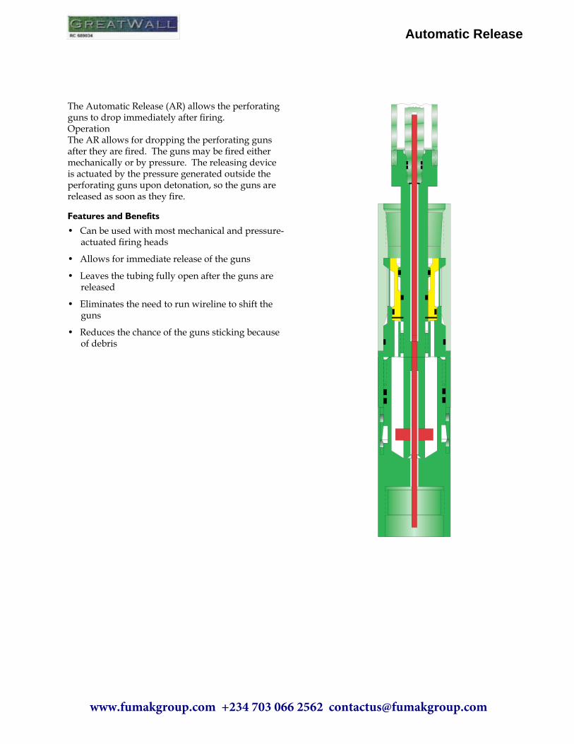
The Automatic Release (AR) allows the perforating guns to drop immediately after firing.OperationThe AR allows for dropping the perforating guns after they are fired. The guns may be fired either mechanically or by pressure. The releasing device is actuated by the pressure generated outside the perforating guns upon detonation, so the guns are released as soon as they fire.
Features and Benefits
• Can be used with most mechanical and pressure-actuated firing heads
• Allows for immediate release of the guns
• Leaves the tubing fully open after the guns arereleased
• Eliminates the need to run wireline to shift theguns
• Reduces the chance of the guns sticking becauseof debris
Automatic Release
www.fumakgroup.com +234 703 066 2562 [email protected]

The ported Balanced Isolation Tool (BIT) assembly is used where either packer selection or well conditions preclude the use of a venting device. The ported BIT assembly replaces the fill disc assembly and is used in place of a perforated sub. The BIT prevents contami-nation of the fluid below it from the fluid above it. Debris or solids in the fluid above cannot pass through the glass disc that is in the floating piston. The glass disc prevents debris from setting on the firing head. Pressure is balanced across the glass barrier through equalizing ports in the piston. The ported BIT assem-bly is run between the firing head and packer. The recommended minimum distance from the BIT to the firing head is 30 ft.
Operation
The basic components of the BIT are a floating piston with a glass disc, a ported lower housing, and a top housing. The ported BIT is run with clean fluid below it. The upward travel of the floating piston is limited by the bottom of the top sub. A pressure increase above the glass barrier causes the piston to move down and forces fluid below the glass barrier out of the bleeder ports. A pressure increase below the glass barrier forces the piston to move up or forc-es fluid out of the bleeder ports. The piston moves up or down within its limits to prevent the glass barrier from breaking. The glass barrier remains intact until the bar passes through it. As fluid enters or leaves the tubing through the ports, debris on the glass barrier is washed off.
Features and Benefits
• Allows mud and debris to be circulated off theglass barrier through the flow ports above theglass barrier
• Allows displacement of the tubing with a lighterfluid or nitrogen before firing the guns
• Allows swabbing of the tubing to achieve differ-ential pressure
• Allows stopping and circulating at any depthsince flow ports are always open
• Can be run with either a mechanical or pressure-actuated firing head
Balanced Isolation Tool
Balanced Isolation Tool
www.fumakgroup.com +234 703 066 2562 [email protected]

Maximum Differential Bar Vent
The Maximum Differential Bar Vent Assembly (MDBV) is a vent run between the perforating guns and the packer. After the packer is set, the opening of the vent creates communication between the tub-ing and rathole. The vent is opened by breaking the plug inside the tool and allowing the sleeve to uncov-er the ports. Running the MDBV allows the opera-tor to run the tubing in the well with no hydrostatic pressure in the tubing.
Operation
The MDBV is held closed by a chamber of silicone fluid, which keeps a spring compressed. When the silicone fluid is released from the chamber, the spring extends and opens the vent. Once the break plug is broken, the silicone fluid drains into the tubing. The MDBV should not be used when the hydrostatic pressure in the tubing exceeds 1,000 psi. If you wish to open the vent before dropping the detonating bar, you can drop a special tube that will open the vent and not fire the guns. When the bar is dropped, it will pass through the tube and fire the guns.
Features and Benefits
• Operates with a minimum amount of fluid in thetubing
• Allows maximum differential pressure when per-forating in lower-pressure formations
• Does not depend on tubing hydrostatic pressureto operate
• Is assisted mechanically by an operating spring tohelp ensure full and complete opening
• Can be used in wells with open perforations toachieve an underbalance when guns are fired toadd new perforations
Maximum Differential Bar Vent
www.fumakgroup.com +234 703 066 2562 [email protected]

Bar Pressure Vent
The Bar Pressure Vent (BPV) is designed to achieve a differential pressure between the formation and tub-ing string. The tool safely allows a differential pres-sure in wells with existing open perforations or in unperforated wells. The BPV is an internal sliding-sleeve tool, actuated by pressure in the tubing. It is run between the packer and the guns.
Operation
The BPV consists of a ported housing and a sliding sleeve. The sliding sleeve is isolated from the tubing pressure by a break plug with a hollow center. The BPV is activated when the detonating bar is dropped through the tubing and shears the hollow break plug. This action allows the pressure in the tubing to force the sleeve upward, uncovering the ports. A lock ring locks the sleeve open. The detonating bar continues downward to strike the firing head. If the inward dif-ferential pressure across the tool exceeds 2,000 psi, it is strongly recommended that a pressure differential reduction stub be installed above the BPV. If you wish to open the vent before dropping the detonating bar, you can drop a special tube that will open the vent and not fire the guns. When the bar is dropped, it will pass through the tube and fire the guns.
Features and Benefits
• Offers an inexpensive way to create the necessaryunderbalance
• Allows the hole to be totally contained at the well-head before the surge
• Once the port is opened, the sleeve is locked inplace
• Can be run with any packer
• Does not rely on tubing manipulation; hydrostaticpressure in the tubing is the only force required
Bar Pressure Vent
www.fumakgroup.com +234 703 066 2562 [email protected]
www.fumakgroup.com +234 703 066 2562 [email protected]

Pressure-Operated Vent
The Pressure-Operated Vent (POV) is designed to achieve a differential pressure between the formation and tubing string and to provide a way to open the vent and test the packer before the guns are fired. When the guns have been positioned and the packer has been set, the predetermined amount of fluid is added to the tubing. Adding the fluid into the tub-ing causes the POV to open and creates the proper pressure differential before firing. Nitrogen may also be used with, or in place of, the fluids to obtain the necessary hydrostatic pressure in the tubing.
Operation
The POV consists of a ported housing, a sliding sleeve, and a set of shear pins. The sleeve is held in the closed position by a variable number of shear pins. The pins are isolated from annular pressure and are only exposed to the tubing hydrostatic. The POV will open when the proper amount of hydrostatic pressure is ap-plied to the shear pins. The amount of hydrostatic it takes to open the POV depends on how many shear pins are installed in the tool. When the pins shear, the hydrostatic pressure forces the sleeve upward, which uncovers the flow ports. The sleeve is then locked into the open position.
Features and Benefits
• Allows the vent to be opened without the gunsbeing fired
• Allows the packer to be tested before the guns are fired
• Fills tubing automatically when run with VCV
• Can be run with mechanical or pressure-actuatedfiring heads
• Is useful in highly deviated wells
• Is compatible with any packer
Pressure-Operated Vent
www.fumakgroup.com +234 703 066 2562 [email protected]

Vann™ Circulating Valve
The Vann™ Circulating Valve (VCV) is designed to be used as a fillup valve or as a circulating valve for displacing well fluids before setting a packer. After the fluid is displaced, the operator applies pressure to the tubing or annulus to rupture a disc and close the VCV.
Operation
The VCV consists of a ported housing, a sliding sleeve, and a rupture disc, which must be ordered separately. The sliding sleeve, which has two air chambers, is open while the tool is run in the hole. The rupture disc is available for different pressure ratings as need-ed. The amount of hydrostatic pressure required to actuate the VCV depends on the rating of the rupture disc. Once the disc ruptures, the hydrostatic pressure enters the lower air chamber through the ruptured disc, forcing the sliding sleeve upward to cover the flow ports. Operating pressure can be pump pressure applied after the VCV is at the bottom of the well or applied by hydrostatic pressure when the tool is run in the hole.
Features and Benefits
• Can be used as a circulating and shutoff valve
• Is often run with other venting or productiondevices
• Is economical and reusable
Vann™ Circulating Valve
www.fumakgroup.com +234 703 066 2562 [email protected]

Annulus-Pressure Crossover Assembly
The Annulus-Pressure Crossover Assembly (APCA) allows the use of annulus pressure to actuate any one of several firing heads. This assembly is compatible with retrievable packers of all types and sizes.
Operation
The APCA creates a pressure chamber above the firing head that is equalized with the pressure in the casing annulus. Once the packer has been set, the pressure on the annulus can be increased to actuate a pressure-actuated firing head. The pressures in the annulus and the tubing can also be manipulated to create the differential pressure necessary to actuate a differential-type firing head.
Features and Benefits
• May be used as the annulus firing system on wellswith nonfull-opening test tools and partially filled drillstring
• May be used as the annulus firing system on hori-zontal wells
• Allows the use of below-packer venting devicesalong this assembly
Annulus-Pressure Crossover Assembly
www.fumakgroup.com +234 703 066 2562 [email protected]

Below-Packer Vent Device
The Below-Packer Vent Device (BPVD) was devel-oped for use with the Annulus-Pressure Crossover Assembly (APCA). Surface pressure applied to the annulus is transmitted through the APCA to a closed chamber below the BPVD and above a pressure-responsive firing head. The BPVD can be set to work before or after the perforating assembly is detonated.
Operation
To open the BPVD, a predetermined annulus pres-sure is transmitted through the APCA to below the BPVD. This pressure then ruptures a disc in the lower housing of the BPVD. An actuating piston then forces the venting sleeve away from the produc-tion ports. This action establishes communication with the tubing string.
Features and Benefits
• Does not require tubing hydrostatic pressure tooperate
• Can operate in highly deviated wells
• Can be used in wells with low formation pressure
• Eliminates nitrogen requirements
• Allows maximum underbalance
• Is compatible with several types of firing heads
• Features reliable and very accurate pressure re-sponse
Below-Packer Vent Device
www.fumakgroup.com +234 703 066 2562 [email protected]
www.fumakgroup.com +234 703 066 2562 [email protected]

Description
The Fill Disc Assembly (FDA) is used where either packer selection or well conditions preclude the use of a venting device. The FDA is used in place of a perforated sub, and replaces the Balanced Isolation Tool in wells with reasonably clean fluids. The glass disc prevents debris from settling on the firing head. Pressure is equalized across the glass disc.The FDA is run between the firing head and packer. The recommended minimum distance from the FDA to the firing head is 30 ft.
Features and Benefits
The FDA• Allows debris to be circulated off the glass disc
through the flow ports above the glass disc
• Acts as a perforated sub for circulating fluid dis-placement with nitrogen and swabbing
• Can be run with either a mechanical or pressure-actuated firing head
Operation
The FDA consists of a ported housing with a glass disc installed in the ID across the lower set of ports. The disc is not sealed, so pressure can equalize across the glass. Any debris falling out of the tubing or fluid above the glass will land on the glass disc. This debris can be circulated off the disc, or if it is not a large amount, it will be displaced out the ports by the detonating bar falling through it. Once the bar breaks through the disc, it should be falling in clean fluid all the way to the firing head. In mud systems or wells with a known debris problem, the Balanced Isolation Tool is recommended in place of the FDA.
Fill Disc Assembly
Fill Disc AssemblyC
N03
254
www.fumakgroup.com +234 703 066 2562 [email protected]