Industrial Refrigeration Systems: Floating Head Pressure Control ...
Bulletin T40-HPC-AG-1
Head Pressure Control Application Guide
for Air-Cooled Condensers and Condensing Units
1101111
17/09/17
GENERALWhen air-cooled condensers or condensing units are in-stalled outdoors, they will be subjected to varying ambient temperatures. This variance could be as much as 120°F (48.9 °C) of swing throughout the summer and winter seasons and will have a major impact on the performance of the condenser. As the ambient temperature drops, the condenser capacity will increase due to the wider tem-perature difference between ambient and condensing temperature. As this happens, the condensing temperature will also drop as the system finds a new balance point. Although overall system capacity will increase, other problems can occur. The capacity of an expansion valve is affected by both the liquid temperature entering the valve and the pressure drop across it. As the condensing tem-perature decreases, the pressure drop across the meter-ing device also decreases. This lower pressure drop will then decrease the capacity of the valve. Although lower liquid temperatures increase the capacity of the metering device, the increase is not large enough to offset the loss due to the lower pressure drop. To provide adequate pres-sure drop, some form of head pressure control is required. Refer to the following design methods (covered in order of simplicity and features).
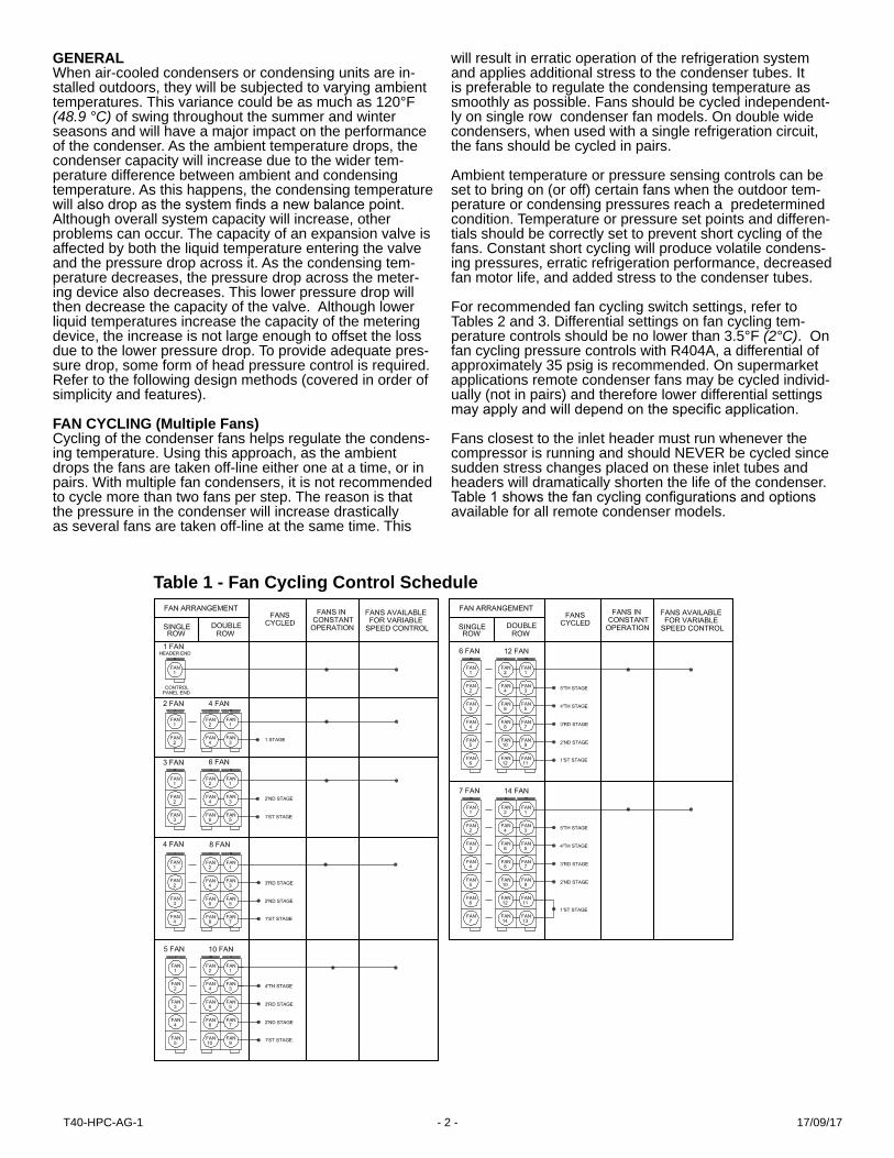
FAN CYCLING (Multiple Fans) Cycling of the condenser fans helps regulate the condens-ing temperature. Using this approach, as the ambient drops the fans are taken off-line either one at a time, or in pairs. With multiple fan condensers, it is not recommended to cycle more than two fans per step. The reason is that the pressure in the condenser will increase drastically as several fans are taken off-line at the same time. This
will result in erratic operation of the refrigeration system and applies additional stress to the condenser tubes. It is preferable to regulate the condensing temperature as smoothly as possible. Fans should be cycled independent-ly on single row condenser fan models. On double wide condensers, when used with a single refrigeration circuit, the fans should be cycled in pairs.
Ambient temperature or pressure sensing controls can be set to bring on (or off) certain fans when the outdoor tem-perature or condensing pressures reach a predetermined condition. Temperature or pressure set points and differen-tials should be correctly set to prevent short cycling of the fans. Constant short cycling will produce volatile condens-ing pressures, erratic refrigeration performance, decreased fan motor life, and added stress to the condenser tubes.
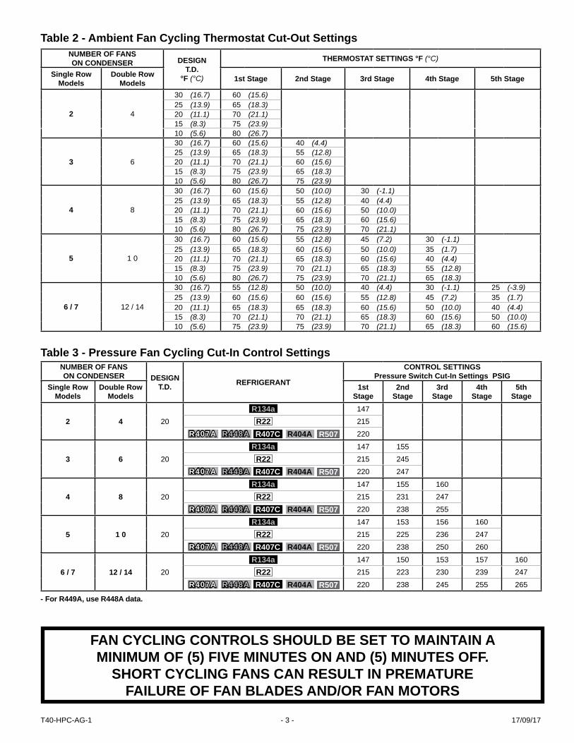
For recommended fan cycling switch settings, refer to Tables 2 and 3. Differential settings on fan cycling tem-perature controls should be no lower than 3.5°F (2°C). On fan cycling pressure controls with R404A, a differential of approximately 35 psig is recommended. On supermarket applications remote condenser fans may be cycled individ-ually (not in pairs) and therefore lower differential settings may apply and will depend on the specific application.
Fans closest to the inlet header must run whenever the compressor is running and should NEVER be cycled since sudden stress changes placed on these inlet tubes and headers will dramatically shorten the life of the condenser. Table 1 shows the fan cycling configurations and options available for all remote condenser models.
Table 1 - Fan Cycling Control Schedule
17/09/17T40-HPC-AG-1 - 2 -
NUMBER OF FANS ON CONDENSER DESIGN
T.D.°F (°C)
THERMOSTAT SETTINGS °F (°C)
Single Row Models
Double Row Models 1st Stage 2nd Stage 3rd Stage 4th Stage 5th Stage
2 4
30 (16.7) 60 (15.6)25 (13.9) 65 (18.3)20 (11.1) 70 (21.1)15 (8.3) 75 (23.9)10 (5.6) 80 (26.7)
3 6
30 (16.7) 60 (15.6) 40 (4.4)25 (13.9) 65 (18.3) 55 (12.8)20 (11.1) 70 (21.1) 60 (15.6)15 (8.3) 75 (23.9) 65 (18.3)10 (5.6) 80 (26.7) 75 (23.9)
4 8
30 (16.7) 60 (15.6) 50 (10.0) 30 (-1.1)25 (13.9) 65 (18.3) 55 (12.8) 40 (4.4)20 (11.1) 70 (21.1) 60 (15.6) 50 (10.0)15 (8.3) 75 (23.9) 65 (18.3) 60 (15.6)10 (5.6) 80 (26.7) 75 (23.9) 70 (21.1)
5 1 0
30 (16.7) 60 (15.6) 55 (12.8) 45 (7.2) 30 (-1.1)25 (13.9) 65 (18.3) 60 (15.6) 50 (10.0) 35 (1.7)20 (11.1) 70 (21.1) 65 (18.3) 60 (15.6) 40 (4.4)15 (8.3) 75 (23.9) 70 (21.1) 65 (18.3) 55 (12.8)10 (5.6) 80 (26.7) 75 (23.9) 70 (21.1) 65 (18.3)
6 / 7 12 / 14
30 (16.7) 55 (12.8) 50 (10.0) 40 (4.4) 30 (-1.1) 25 (-3.9)25 (13.9) 60 (15.6) 60 (15.6) 55 (12.8) 45 (7.2) 35 (1.7)20 (11.1) 65 (18.3) 65 (18.3) 60 (15.6) 50 (10.0) 40 (4.4)15 (8.3) 70 (21.1) 70 (21.1) 65 (18.3) 60 (15.6) 50 (10.0)10 (5.6) 75 (23.9) 75 (23.9) 70 (21.1) 65 (18.3) 60 (15.6)
NUMBER OF FANS ON CONDENSER DESIGN
T.D. REFRIGERANT
CONTROL SETTINGSPressure Switch Cut-In Settings PSIG
Single Row Models
Double Row Models
1st Stage
2nd Stage
3rd Stage
4th Stage
5th Stage
2 4 20R134a 147
R22 215R407A R448A R407C R404A R507 220
3 6 20R134a 147 155
R22 215 245R407A R448A R407C R404A R507 220 247
4 8 20R134a 147 155 160
R22 215 231 247R407A R448A R407C R404A R507 220 238 255
5 1 0 20R134a 147 153 156 160
R22 215 225 236 247R407A R448A R407C R404A R507 220 238 250 260
6 / 7 12 / 14 20R134a 147 150 153 157 160
R22 215 223 230 239 247R407A R448A R407C R404A R507 220 238 245 255 265
Table 2 - Ambient Fan Cycling Thermostat Cut-Out Settings
Table 3 - Pressure Fan Cycling Cut-In Control Settings
FAN CYCLING CONTROLS SHOULD BE SET TO MAINTAIN A MINIMUM OF (5) FIVE MINUTES ON AND (5) MINUTES OFF.
SHORT CYCLING FANS CAN RESULT IN PREMATURE FAILURE OF FAN BLADES AND/OR FAN MOTORS
- For R449A, use R448A data.
17/09/17T40-HPC-AG-1 - 3 -

VARIABLE SPEED MOTOR CONTROL ON HEADER FAN (used with fan cycling )If additional head pressure control is required beyond the last step of fan cycling, variable fan motor speed methods may be used. A varying motor speed may be accom-plished using a modulating temperature or modulating pressure control. Varying the speed of the header Fan motor can be achieved by using a varying voltage control-ler (triac sine wave chopper), variable frequency drives (VFD), or EC (electronically commutated) motors. EC motors are preferred due to their simplicity, reliability, and energy savings.
VARIABLE SPEED EC MOTOR CONTROL ON ALL FANSEC (electronically commutated) motors can be controlled to provide a similar function to the fan cycling method by constantly varying their speed and air flow through the condenser as opposed to the sudden air flow change from a fan cycling on and off. Air cooled condensers and condensing units utilizing EC motor technology offer many benefits; Improved efficiency, reduced sound levels, vari-able speed head pressure control, refrigerant savings, energy savings and reliability.
Improved EfficiencyEC motors are more energy efficient than conventional AC (PSC and shaded pole) motors. Unlike AC motors that see efficiency decrease as the motor speed is decreased, an EC motor efficiency remains consistent throughout its range of operation.
Reduced SoundAs EC motor speeds vary for different operating conditions they also offer reduced sound levels when compared to conventional motor running full speed. Sound levels are reduced on cooler days and in evenings.
Head Pressure ControlEC motors make it easier to maintain stable head pres-sures when motor speeds are varied according to oper-ating conditions. When compared to a conventional fan cycling system, EC motors do a much better job main-taining stable head pressures. System performance is further enhanced with consistent liquid temperatures that ensure optimized operation of the nozzle and TX valve in the evaporator. In colder ambients, special consideration should be given to the use of heated and insulated receiv-ers and wind guard protection on the condenser. (See Table 6 for recommendations)
Refrigerant SavingsSystem charges can be reduced by 30 – 40% by utiliz-ing variable speed EC motors to control head pressures. The elimination of the head pressure control valve also eliminates the need for any extra winter refrigerant charge required to flood the condenser.
Energy SavingsWhen a system’s head pressure is controlled using a flooded head pressure control valve, the condenser fan motor runs at 100% fan speed all of the time. When head pressure is controlled using an EC motor and the motor speed is varied according to operating conditions, this results in lower energy consumption of the motor. The amount of energy to be saved depends on; ambient condi-tions, system operation conditions and head pressure set point.
Simplicity and ReliabilityThe installation and control of EC motors is very simple compared to other methods of speed control used on conventional AC motors. Lower running operating tem-peratures and smooth transitional speed changes make EC motors durable and reliable. To provide speed control, a separate electronic controller and pressure transducer sensing the high side pressure is required. This provides fan speed regulation down to the lowest RPM and fan pul-sation where applicable. For colder ambient temperatures 10˚F (-12˚C) and below, a further positive means of control is required (such as flooding valve type methods or new Limitrol+ option).
For complete details on controllers, please refer to the “Controller Application Guide”, Bulletin # B40-C-AG
CONDENSER FLOODING (REFRIGERANT REGULATING CONTROLS)During colder 10˚F(-12˚C) and below ambient tempera-tures , reducing the condenser fan air flow may not be enough to maintain an acceptable minimum 70˚F(21˚C) condensing temperature. This requires the condenser’s primary heat transfer surface to be reduced . This can be achieved by displacing a portion of the internal condenser volume with vapour free liquid refrigerant. This common control method is achieved by the use of head pressure control flooding valves. The specific type of regulating valve and piping configuration will vary with system size (capacity), application and desired user features. The amount of the additional liquid charge required to maintain an adequate head pressure (condensing temperature) will vary with both the actual ambient temperature and the sys-tem application (low, medium, or high temperature evapo-rating temperatures). Depending on actual ambient and specific application, the condenser could require flooding charges anywhere between 30 to 95% of the condenser’s internal volume. At lower, colder ambient temperatures below -20˚F(-29˚C), the use of a heated and insulated re-ceiver should be considered. For further details on flooding valve operation and piping arrangements refer to literature provided by the various regulating valve suppliers (Spor-lan, Parker, etc.).
17/09/17T40-HPC-AG-1 - 4 -
This new floating head pressure control option, Limitrol+ (Limitrol Plus) has been specifically designed for Air-cooled condensing units and combines various technolo-gies into a responsive system that floats the head pres-sure below 90˚F(32˚C) condensing temperatures, saving energy and reducing environmental impact. Unlike previ-ous head pressure flooding valve applications, this sys-tem uses EC motor technology and condenser portioning control to provide reduced operating refrigerant charges without the need for a flooding valve and oversized re-ceiver. As a result, this non-flooding system can provide control at much colder ambient temperatures where previ-ous designs have proven ineffective.
Limitrol+ offers the following benefits:• Reduces compressor energy consumption and run time• Utilizes EC motor technology which further reduces energy consumption• Lowers environmental impact through reduced refrigerant use• Provides stable system performance at very low temperatures
To see how much Limitrol+ can save on energy and refrig-erant, compared to conventional flooded valve systems, refer to Tables 4 and 5.
NEW LIMITROL+ FLOATING HEAD PRESSURE CONTROL SYSTEM
(Patent Pending)
17/09/17T40-HPC-AG-1 - 5 -

Table 4 - Percentage & Dollar KWH Savings over Flooded Valve Systems
TE ModelHP
*Flood Valve-20°F Ambient
*Limitrol+-20°F Ambient
% Charge *Savings
3 M 8.6 6 30%3, 3.5, 4 L 9.3 6.4 31%
5 H,M 18.1 11.9 34%6, 7.5 L 20.0 12.9 36%7.5 H 18.2 12 34%
7.6, 8, 10 H 20.1 15.9 21%9, 10 L 22.2 17 23%
12, 15, 20 H 33.0 25.8 22%12, 13, 15,22 L 36.6 27.6 25%
TMS ModelHP
*Flood Valve-20°F Ambient
*Limitrol+-20°F Ambient
% Charge *Savings
7.5,7.6 M,H 22.6 15.5 31%7.5 L 24.6 16.5 33%8 H,M 21.4 17.2 20%10 H,M 29.3 22.9 22%
10 L 23.5 18.2 23%12L 32.4 24.5 24%
12,15 H,M 37.4 29.2 22% 22L 41.4 31.2 25%
TVS Standard Model HP
*Flood Valve-20°F Ambient
*Limitrol+-20°F Ambient
% Charge *Savings
8 V,10L,12 L 30 19.8 34%12V,16V,15L 37.2 24.4 34%
15 M, H 34.2 26.8 22%20, 22 ,25 M,H 44.9 34.9 22%
20,22 L 37.8 28.7 24%20V,25V,27L,30L 49.9 37.4 25%
30 M,H 56.9 44.2 22%30V,40 L 63.2 44.1 30%35 M,H 66.6 51.9 22%40 M,H 81.8 62.4 24%50 M,H 88.3 67.4 24%
TVS Hi-Eff. Model HP
*Flood Valve-20°F Ambient
*Limitrol+-20°F Ambient
% Charge *Savings
11,13L 41.4 28.6 31%16,21,23L 49.9 37.2 25%
16M,H 44.9 34.9 22%21,23M,H 56.9 44.2 22%26,28,31L 63.2 47.4 25%
31M,H 81.8 62.4 24%36M,H 131.6 98.9 25%
41,51,M,H 163.4 120.9 26%
Table 5 - Refrigerant Savings over Flooded Valve Systems
* The above is a BIN Hour Analysis. Weather data was used from ASHRAE Weather Data Viewer and electrical rates for each city are based on June 2013 data from EIA (U.S. Energy Information Administration).** Above numbers do not include refrigerant savings, and further cost savings can be expected.
* Note: Does not include evaporator and liquid line charge Shaded area has multiple fans with applicable fans cycled off.TMD Double compressor models are 2 x above TMS single model. TVD Double compressor models are 2 x above TVS single model
POTENTIAL SAVINGS
MODELPhiladelphia,
PANew York,
NYBoston,
MACharlotte,
NCAtlanta,
GALos Angeles,
CASt Louis,
MOSt. Paul,
MNToronto,
ON% $ % $ % $ % $ % $ % $ % $ % $ % $
5 HP Cooler 22 616 23 1,099 25 1,081 18 474 16 521 16 835 20 624 25 798 27 638
7.5 HP Cooler 21 1,008 22 1,805 23 1,707 18 843 17 954 17 1,499 19 1,053 24 1,270 25 1,000
10 HP Cooler 18 1,204 18 2,131 20 2,095 15 975 14 1,089 18 2,446 16 1,227 20 1,529 21 1,223
15 HP Cooler 19 1,852 20 3,300 21 3,170 16 1,567 15 1,767 19 3,570 17 1,916 22 2,337 22 1,834
6 HP Freezer 24 903 25 1,621 26 1,548 21 753 20 848 23 1,548 22 928 26 1,119 27 891
7.5 HP Freezer 21 994 21 1,783 23 1,726 17 800 16 891 18 1,591 19 1,012 23 1,255 24 1,004
13 HP Freezer 19 1,425 19 2,535 21 2,450 16 1,150 15 1,286 15 2,110 17 1,471 21 1,798 22 1,428
15 HP Freezer 18 1,602 19 2,846 20 2,717 16 1,312 15 1,479 14 2,224 17 1,672 20 2,009 21 1,587
17/09/17T40-HPC-AG-1 - 6 -
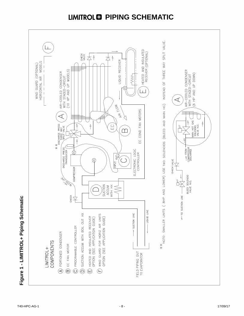
Refer to the following Limitrol+ condensing unit piping diagram FIG. 1 shown below. The Limitrol+ standard design includes the following four main components:
• Portion controlled Air-cooled Condenser- (A). • EC (Electronically commutated) condenser fan motor(s)-(B).• Electronic programmable logic controller w/pressure transducer- (C).• Suction accumulator with Liquid heat–exchanger-(D).
Also included are the following optional (application re-lated) components:
• Heated and insulated receiver-(E)• Wind guard for horizontal air flow units -(F)
The Limitrol+ provides optimized compressor and con-denser fan energy savings by lowering the condensing pressure and power consumption during low operating loads and cooler ambient temperature conditions.
An electronic logic controller (C) senses the discharge pressure (from the pressure transducer) and targets a fac-tory pre-set 70˚F(21˚C) floating condensing temperature. The condenser EC fan motor (B) responds to a DC voltage signal input that directly controls the fan speed. The DC signal is primarily based upon the discharge transducer pressure which is affected by the evaporator load and condensing unit ambient temperature. At peak ambient temperatures the condenser will be required to operate at full capacity using maximum condenser fan speeds. As the ambient becomes cooler less condenser capacity is required. The condensing temperature can then float down towards the minimum condensing temperature by the fan starting to slow down.Once the condenser fan has reached its lowest functional minimum speed (when the ambient becomes much colder) a section of the condenser surface (A) can be removed (staged) in order to continue to provide the minimum con-densing temperature set point. Note that in a conventional system this is normally accomplished by adding a head pressure control flooding valve and adding extra liquid refrigerant into the receiver allowing liquid to back up into the condenser displacing the active condenser surface. During the initial transition with the new condenser staging (smaller portioning) the fan motor must then respond to an increased air flow requirement .The electronic logic con-troller (C) will accordingly send a new signal to increase the EC motor (B) RPM. From this point the EC motor can vary its range of RPM in order to further control the head pressure at the lower ambient.
During the lower ambient stage if the load or ambient temperature increases and the condenser fan reaches its functional maximum speed a portion of the condenser (A) is then added back (staged) providing added necessary capacity to maintain the required control setpoint. Note that in a conventional head pressure control valve system, the extra liquid that had been previously required to be backed up in the condenser would then need to be trans-ferred and stored back into the receiver (requiring oversiz-ing). During the initial transition with the new condenser staging (larger portioning) the fan motor must then re-spond to a decreased air flow requirement .The electronic logic controller (C) will then send a new signal to decrease the EC motor (B) RPM.
Limitrol+ Logic Controller and Condensing unit wiringLogic control, EC motor and condenser staging wiring are covered in FIG. 2 (8 hp and smaller units) and FIG.3 (over 8 HP, larger units ) wiring diagrams.
Logic control is provided by the electronic controller which senses the discharge pressure through the pressure transducer. The controller provides condenser portion-ing control (through output relays) and DC signal control (though analog outputs) for the EC motor speed. There are two different analog signals (0-10VDC output ) for the EC motor. The first analog signal is activated during the cold ambient when the condenser has been staged (portioned) and the second analog signal is activated during the warm ambient when the condenser has not been staged (not portioned). The 0-10V DC signal output directly controls the fan speed (RPM). Refer to the control manufacturer’s operating instructions and the condensing unit QSU (quick set up) set point instruction sheet for details on operation and programming.
The wiring method for Condenser staging varies with the unit model.The smaller units (8 HP and lower) close off the condenser portion during the cold ambient by a discharge line solenoid valve (NC normally closed). Also another smaller bleed line solenoid valve (NC) is used to purge any refrigerant or oil from the idle condenser portion over to the suction side. Both are wired through the controller output relays. The Larger units (above 8 HP) use a special three way splitting valve (with internal bleed function) to re-place the discharge solenoid valve and bleed/purge valve function. The use of check valves prevent any migration/logging of refrigerant and oil into the idle condenser por-tion during the cold ambient stage.
THEORY OF OPERATION
17/09/17T40-HPC-AG-1 - 7 -
Figu
re 1
- LI
MIT
RO
L+ P
ipin
g Sc
hem
atic
PIPING SCHEMATIC
17/09/17T40-HPC-AG-1 - 8 -
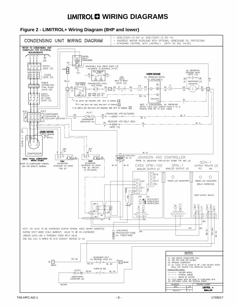
Figure 2 - LIMITROL+ Wiring Diagram (8HP and lower)
WIRING DIAGRAMS
17/09/17T40-HPC-AG-1 - 9 -

Figure 3 - LIMITROL+ Wiring Diagram (Over 8HP)
WIRING DIAGRAMS
17/09/17T40-HPC-AG-1 - 10 -

Under colder ambient temperatures there could exist limitations on the effective control of the minimum con-densing pressure. Proper design of the evaporator must be reviewed to ensure circuiting, distributor nozzles, distributor tubes, and expansion valve type (balanced port required) and size are properly designed to operate at the lower pressures and liquid temperatures. The use of the following optional components should be considered. For an overall summary of recommended ambient ranges and comparisons to other head pressure control methods, refer to Table 6.
Limitrol + Heated and Insulated ReceiverFor colder 10˚F (-12˚C) and lower ambient temperatures the addition of a heated and insulated receiver option is recommended (this ensures adequate pressure is avail-able during start-up after any prolonged off cycle).
Limitrol+ Wind Guard (Horizontal Air Flow Units)On smaller condensing units that use horizontal air flow condensers, special attention to the unit site location must be considered. Unprotected, strong cold winds blowing directly on the condenser face can affect the control of the condensing temperature. In colder, northern climates at temperatures of 0˚F (-18˚C) and lower the use of an op-tional wind guard should be considered or where feasible consider locating the unit beside a building structure or barrier where it may be protected from the wind.
Limitrol+ with installed Flooding Valve (for extreme cold temperatures)If extreme cold -20˚F(-29˚C) and below ambient tempera-tures and excessive winds exist, the use of an adjustable flooding valve (with added refrigerant charge) should be considered. The valve must be adjusted to a lower setting than the logic controller set point and must be installed at the condenser common liquid line downstream of the liquid lines (and check valve(s) of the two condenser staging cir-cuits). Limitrol+ still offers an advantage over conventional flooding systems due to the fact that only the portioned half of the condenser will need to be flooded minimizing the refrigerant charge.
Limitrol + with Capacity Control – compressor unload-ing During the cold ambient stage system power consumption is reduced and compressor efficiency is increased (from the lower condensing temperatures). Also system capac-ity is further increased from the net refrigeration effect of the colder sub-cooled liquid temperatures. This increase of capacity will affect the summer design rating of the compressor/evaporator balance (evaporator TD). Optional compressor unloading or other control methods (i.e. hot gas bypass) may be required on any medium or high temperature application requiring specific humidity control. The use of compressor unloading will also result in further KWH energy savings (reducing the power consumption and increasing compressor efficiency).
METHOD OF HEAD PRESSURE ENERGY SAVINGS
RELIABILITY/ PERFORMANCE
REFRIGERANT SAVINGS
AMBIENT RANGE** 120°F to...
FAN CYCLING ONLY POOR FAIR FAIR 50°FFAN CYCLING w/VARIABLE SPEED ON HEADER FAN FAIR FAIR GOOD 20°FFLOODING VALVE w/FAN CYCLING POOR GOOD POOR -40°FVARIABLE SPEED EC MOTORS (ONLY) NO WIND PROTECTION* VERY GOOD GOOD VERY GOOD 10°F
VARIABLE SPEED EC MOTORS (ONLY) w/WIND PROTECTION (GUARD OR WALL)* VERY GOOD VERY GOOD VERY GOOD 0°F
LIMITROL+ STANDARD PACKAGE* HORIZONTAL CU w/NO WIND PROTECTION EXCELLENT EXCELLENT EXCELLENT -10°F
LIMITROL+ STANDARD PACKAGE* VERTICAL UNITS & HORIZONTAL UNITS w/WIND PROTECTION EXCELLENT EXCELLENT EXCELLENT -20°F
LIMITROL+ w/FLOODING VALVE ON 1/2 COND HORIZONTAL & VERTICAL UNITS EXCELLENT EXCELLENT GOOD -40°F
Table 6 - Head Pressure Control Method Comparison And Application Guide
APPLICATION LIMITATIONS
* HEATED AND INSULATED RECEIVER REQUIRED ON UNITS OPERATING IN AMBIENTS <10°F
** These are recommended temperature application ranges only and all facets of each installation need to be considered when deciding which method of head pressure control to use. Location, mounting orientations, prevailing winds, wall/barriers, etc., will have an impact on which method is appropri-ate for the application.
17/09/17T40-HPC-AG-1 - 11 -

PRODUCT SUPPORT RESOURCES
web: t-rp.com/warranty email: [email protected]: 1-844-893-3222 x501
web: t-rp.com/supportemail: [email protected]
call: 1-844-893-3222 x521
email: [email protected]: 1-844-893-3222 x529
web: t-rp.com/parts email: [email protected]
call: 1-844-893-3222 x501
email: [email protected]: 1-844-893-3222 x501
email: [email protected]: 1-844-893-3222 x503
Due to the manufacturer’s policy of continuous product improvement, we reserve the right to make changes without notice.
NATIONAL REFRIGERATION & AIR CONDITIONING CANADA CORP.159 Roy Blvd. Brantford Ontario Canada N3R 7K1PHONE: (519) 751-0444 800-463-9517 FAX (519) 753-1140 www.t-rp.com
17/09/17